faujasite-type films synthesized by seeding
TRANSCRIPT

Faujasite-type ®lms synthesized by seeding
Magdalena Lassinantti, Jonas Hedlund, Johan Sterte *
Division of Chemical Technology, Lule�a University of Technology, SE-971 87 Lule�a, Sweden
Received 5 July 1999; received in revised form 4 October 1999; accepted 5 October 1999
Abstract
Thin and continuous Faujasite-type ®lms were synthesized on a-alumina wafers using a seeding technique. Surface
modi®ed wafers were seeded with colloidal zeolite Y crystals prior to ®lm growth in a synthesis mixture. The e�ects of
hydrothermal treatment on ®lm thickness, morphology and preferred orientation of the crystals constituting the ®lm
were investigated using scanning electron microscopy and X-ray di�raction. During hydrothermal treatment a pre-
cipitate formed rapidly, leaving an almost clear solution in the upper part of the reactor. Experiments at 60±100°C were
performed with the sample placed in the upper part of the synthesis solution. An increase in the ®lm growth rate with
increasing temperature was observed. Adsorbed seeds were shown to be oriented with the {1 1 1} pyramid, parallel to
the substrate surface. A change in the orientation with ®lm growth was noted, probably due to the attachment of
secondary crystals to the growing ®lm surface. In one experimental series, ®lm growth was e�ected at the bottom of the
tube at 100°C. Faster ®lm growth and multilayered ®lms were obtained. A decrease in the ®lm thickness after prolonged
hydrothermal treatment was observed in all experimental series. This is probably due to the dissolution of the ®lm and
formation of zeolite P in the synthesis solution. The thicknesses of the ®lms synthesized in this work are in the range of
150±2700 nm. The ®lms are promising candidates for use in membrane applications. Ó 2000 Elsevier Science B.V. All
rights reserved.
Keywords: Faujasite; Film; Seeding; Membrane; Ion exchange
1. Introduction
Thin molecular sieve ®lms are of great interestin a number of potential industrial applications,the most interesting one probably being themembranes of various types. Zeolite ®lms formembrane applications must be of an extremelyhigh quality. Even a small number of defects in the
®lm is detrimental to the selectivity of the mem-brane. Moreover, to obtain a high ¯ux through themembrane, the molecular sieve ®lm should be thin.Molecular sieve membranes of Faujasite may be ofparticular interest due to their high aluminumcontent, i.e. their hydrophilicity. The channel sys-tem in Faujasite-type structures is three dimen-sional with equidimensional channels intersectingin a perpendicular fashion. The free aperture di-ameter for the channels is 7.4 �A in NaY [1].
Reports concerning the synthesis of zeolite®lms bring about three di�erent strategies. (i) themethod of direct crystallization, (ii) the vaporphase method, and (iii) methods involving seeding
Microporous and Mesoporous Materials 38 (2000) 25±34
www.elsevier.nl/locate/micromeso
* Corresponding author. Tel.: +46-920-72314; fax: +46-9-
209-1199.
E-mail address: [email protected] (J. Sterte).
1387-1811/00/$ - see front matter Ó 2000 Elsevier Science B.V. All rights reserved.
PII: S 1 3 8 7 - 1 8 1 1 ( 9 9 ) 0 0 2 9 6 - 6

of the substrate surface prior to ®lm synthesis.Applying the third approach, several methodsfor the attachment of seeds to the surface havebeen proposed. Zeolite Y ®lms were synthesizedon tubular a-alumina supports, using a seedingtechnique in which the support was rubbed withNaX zeolite crystals that acted as growth centers[2]. The seeding step was shown to be crucial forthe ®lm formation. In the synthesis of highlyoriented ®lms of zeolite A, glass supports wereimmersed in a colloidal zeolite A suspension toobtain seed crystal layers [3]. This step was re-peated several times in order to obtain a highcoverage of the support with seed crystals. Sili-calite membranes were synthesized by allowingthe silicalite particles in a precursor silicalite/alu-mina ®lm to grow under appropriate synthesisconditions [4]. In this way, the interzeolitic spac-ing in the ®lm was closed, forming a continuousmolecular sieving layer. Kita et al. synthesized aNaY zeolite membrane using a seeding approach[5]. A porous alumina substrate was subjected toa water suspension of NaY seed crystals. Fol-lowing seeding, the ®lm growth was e�ected byhydrothermal treatment in a synthesis solution.The resulting ®lm was 20 lm thick and consistedof intergrown, randomly oriented crystals. Asynthesis procedure known as ``the seed ®lmmethod'' [6±11] has been developed. According tothis method, the substrate surface is modi®ed inorder to facilitate seed adsorption from a seedcrystal sol. The modi®cation required is deter-mined by the type of the surface. For example,negatively charged surfaces are modi®ed by theadsorption of a cationic polymer. The seed ®lmtechnique enables the preparation of very thin®lms and has shown to be applicable to manytypes of supports. Coatings of zeolite Y synthe-sized using this technique have been reported on®bers of cotton, linen and chemi-thermo me-chanical pulp (CTMP)-¯u� [11]. No systematicinvestigation of the preparation of Faujasite-type®lms on inorganic substrates has however beenreported. The scope of the present work was tostudy the e�ects of various synthesis parameterson the crystallization of Faujasite-type ®lms withthe objective of developing preparative proce-dures suitable for membrane preparations.
2. Experimental section
Colloidal crystals of zeolite Y used as seedswere synthesized in a clear homogeneous solu-tion. The molar composition of the synthe-sis mixture was 2.46(TMA)2O:0.032Na2O:Al2O3:3.40SiO2:400H2O [12]. The silica source was tetra-ethoxysilane (TEOS > 98%, Merck) and the alumi-num source was aluminum isopropoxide (Sigma).The alkali sources were tetramethylammoniumhydroxide (TMAOH, Sigma) and a 0.10 M sodiumhydroxide solution (Riedel-deHa�en). The synthesismixture was prepared by adding a mixture ofaluminum isopropoxide, water, TMAOH and a0.10 M sodium hydroxide solution to a mixture ofTEOS and water under vigorous stirring. Follow-ing hydrolysis for 18 h, crystallization was e�ectedunder re¯ux in a polypropylene reactor placed inan oil bath at a temperature of 100°C. After 192 hof hydrothermal treatment, the crystals were puri-®ed by centrifugation and redispersion in a 0.10 Mammonia solution. After each redispersion, theseed sol was allowed to equilibrate for 24 h. Thepuri®cation procedure was repeated twice. Fol-lowing a ®nal redispersion in distilled water, thesolid content and the pH of the sol were adjustedto 1.0% and 10.0, respectively (the latter by addi-tion of a dilute ammonia solution). In order toinvestigate the ion exchange properties of the seedcrystals, two as-synthesized seed sol samples werepuri®ed in the following di�erent media. (i) 0.10 Mammonia solution and (ii) distilled water. Thepuri®cation sequence was the same as that de-scribed above but without the adjustment of thepH and the solid content. An additional samplepuri®ed in a dilute ammonia solution for fourmonths was also investigated. Following puri®ca-tion, the samples were air dried for 18 h at 100°C.
One side polished a-alumina (0 0 0 1) substrateswere mounted vertically in Te¯on holders. Thesubstrates were rinsed in acetone for 5 min in ul-trasound. After ultrasoni®cation, the substrateswere boiled for 5 min in an alkaline solutionhaving the volume composition 5H20:1H2O2:1NH3 (30% H2O2 and 25 wt.% NH3 solution) andin an acidic solution with a volume composition6H2O:1H2O2:1HCl (30% H2O2, 37% HCl). Fol-lowing cleaning, the substrates were treated for
26 M. Lassinantti et al. / Microporous and Mesoporous Materials 38 (2000) 25±34

5 min in a solution containing cationic polymermolecules (0.4 wt.% Redi¯oc 4150, Eka Chemi-cals), adjusted to pH 8.0 by addition of a diluteammonia solution. The substrates were rinsed in a0.1 M ammonia solution to remove excess poly-mer. In the following step, the modi®ed substrateswere immersed in the seed sol for 5 min. After theadsorption of seed crystals, the substrates wererinsed in a dilute ammonia solution to removeexcess crystals. To increase the amount of ad-sorbed seed crystals, the polymer and the seedadsorption steps were repeated once more. Fol-lowing seeding, the substrates (still mounted inholders) were immediately placed in a synthesis gelwith the polished side almost vertical but lean-ing slightly downwards in order to avoid sedi-mentation of crystals formed in the bulk onto thesurface. The molar composition of the synthe-sis solution was 14Na2O:Al2O3:10SiO2:798H2O:3Na2SO4. This solution was prepared by mixingan aqueous solution of sodium metasilicate(Na2SiO3 � 9H2O > 98%, Sigma) with aluminum-sulfate-18-hydrate (Riedel-deHa�en) dissolved in a1.0 M sodium hydroxide solution. The gel washomogenized under stirring for 2 h. A precipitateformed rapidly in the reactor during ®lm synthesis,leaving a clear solution in the upper part of thesynthesis gel. Film growth in the upper part of thesynthesis gel was studied at the temperatures 60°C,80°C and 100°C. Film growth with the substratesplaced in the lower part of the gel was studied at100°C. All the ®lms were grown under static con-ditions at an atmospheric pressure and under re-¯ux. After cooling, the samples were rinsed in adilute ammonia solution. In order to investigatethe events taking place in the bulk of the ®lmsynthesis solution, the bulk product was puri®edby sedimentation and redispersion in dilute am-monia solution. The puri®cation step was repeatedtwice, and the dispersion was air dried at 100°C.Commercial powders of zeolite Y and zeolite P(Eka Nobel) were used as references. The relativeamount of each zeolite in the bulk product wascalculated by dividing the sum of the areas of themost intense peaks in the sample, originating fromthe zeolite investigated, with the same sum ob-tained from the reference sample. As the bulkproduct is a mixture of zeolites Y and P, this
simple equation is applicable because the absorp-tion coe�cients are similar for zeolites Y and P,since a calibration curve based on di�erent massratios of the two zeolites gives a straight line.
Dynamic light scattering (DLS) was used tofollow the growth of the seed crystals using aBrookhaven Instrument BI200SM light scatteringsystem. The thickness and morphology of the ®lmswere investigated using a Philips XL 30 scanningelectron microscope (SEM) equipped with a LaB6
emission source. Top view images were recordedwith a 20° tilt of the specimen. Elemental analysesof seed crystals and crystals formed in the bulkduring ®lm synthesis were performed using anenergy dispersive X-ray spectrometer (EDX, LinkIsis) attached to the SEM. Prior to the SEMcharacterization, the samples were coated with athin layer of gold. A Siemens D5000 powder X-raydi�ractometer (XRD) running in the Bragg±Brentano mode and equipped with a G�obel mir-ror, was used to collect the XRD data in the 2hrange of 5°±35°. Fourier transform infrared(FTIR) spectroscopy measurements were per-formed using a Perkin±Elmer 2000 FTIR spec-trometer.
3. Results and discussion
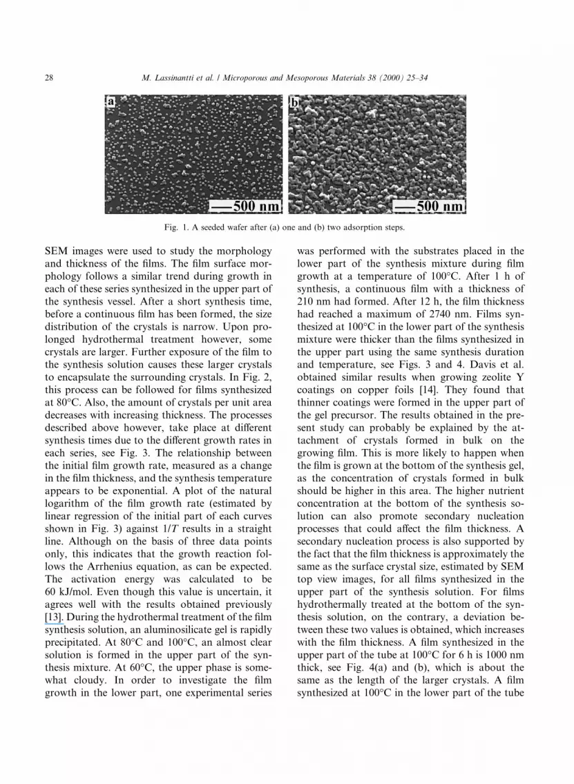
Seed crystals, 70 nm as measured by DLS, wereadsorbed on a-alumina wafers in order to facilitatezeolite growth. After one adsorption step, ap-proximately 30% of the substrate is covered withseed crystals, see Fig. 1(a). An additional adsorp-tion step results in a substantially improved seed-ing, see Fig. 1(b), with a coverage of about 60%. Aseeding procedure involving two steps was used togrow the ®lms. In order to investigate the possi-bility of the ®lm growth without seeding the wafer,an experiment was made where a nonseeded a-alumina wafer was immersed in a synthesis gel for20 h. From the top view of the SEM images (notshown here), it was concluded that no ®lm wasformed on nonseeded substrates.
The in¯uence of synthesis temperature on ®lmsgrown in the upper part of the synthesis gel wasinvestigated using three di�erent temperatures:60°C, 80°C and 100°C. The top and side view
M. Lassinantti et al. / Microporous and Mesoporous Materials 38 (2000) 25±34 27
SEM images were used to study the morphologyand thickness of the ®lms. The ®lm surface mor-phology follows a similar trend during growth ineach of these series synthesized in the upper part ofthe synthesis vessel. After a short synthesis time,before a continuous ®lm has been formed, the sizedistribution of the crystals is narrow. Upon pro-longed hydrothermal treatment however, somecrystals are larger. Further exposure of the ®lm tothe synthesis solution causes these larger crystalsto encapsulate the surrounding crystals. In Fig. 2,this process can be followed for ®lms synthesizedat 80°C. Also, the amount of crystals per unit areadecreases with increasing thickness. The processesdescribed above however, take place at di�erentsynthesis times due to the di�erent growth rates ineach series, see Fig. 3. The relationship betweenthe initial ®lm growth rate, measured as a changein the ®lm thickness, and the synthesis temperatureappears to be exponential. A plot of the naturallogarithm of the ®lm growth rate (estimated bylinear regression of the initial part of each curvesshown in Fig. 3) against 1/T results in a straightline. Although on the basis of three data pointsonly, this indicates that the growth reaction fol-lows the Arrhenius equation, as can be expected.The activation energy was calculated to be60 kJ/mol. Even though this value is uncertain, itagrees well with the results obtained previously[13]. During the hydrothermal treatment of the ®lmsynthesis solution, an aluminosilicate gel is rapidlyprecipitated. At 80°C and 100°C, an almost clearsolution is formed in the upper part of the syn-thesis mixture. At 60°C, the upper phase is some-what cloudy. In order to investigate the ®lmgrowth in the lower part, one experimental series
was performed with the substrates placed in thelower part of the synthesis mixture during ®lmgrowth at a temperature of 100°C. After 1 h ofsynthesis, a continuous ®lm with a thickness of210 nm had formed. After 12 h, the ®lm thicknesshad reached a maximum of 2740 nm. Films syn-thesized at 100°C in the lower part of the synthesismixture were thicker than the ®lms synthesized inthe upper part using the same synthesis durationand temperature, see Figs. 3 and 4. Davis et al.obtained similar results when growing zeolite Ycoatings on copper foils [14]. They found thatthinner coatings were formed in the upper part ofthe gel precursor. The results obtained in the pre-sent study can probably be explained by the at-tachment of crystals formed in bulk on thegrowing ®lm. This is more likely to happen whenthe ®lm is grown at the bottom of the synthesis gel,as the concentration of crystals formed in bulkshould be higher in this area. The higher nutrientconcentration at the bottom of the synthesis so-lution can also promote secondary nucleationprocesses that could a�ect the ®lm thickness. Asecondary nucleation process is also supported bythe fact that the ®lm thickness is approximately thesame as the surface crystal size, estimated by SEMtop view images, for all ®lms synthesized in theupper part of the synthesis solution. For ®lmshydrothermally treated at the bottom of the syn-thesis solution, on the contrary, a deviation be-tween these two values is obtained, which increaseswith the ®lm thickness. A ®lm synthesized in theupper part of the tube at 100°C for 6 h is 1000 nmthick, see Fig. 4(a) and (b), which is about thesame as the length of the larger crystals. A ®lmsynthesized at 100°C in the lower part of the tube
Fig. 1. A seeded wafer after (a) one and (b) two adsorption steps.
28 M. Lassinantti et al. / Microporous and Mesoporous Materials 38 (2000) 25±34

for 6 h, has a crystal size of about 1000 nm,whereas the ®lm thickness is about 1700 nm, seeFig. 4(c) and (d). Moreover, subjecting ®lms syn-thesized at the lower part of the synthesis solutionat 100°C to ultrasound treatment causes the ®lmthickness to decrease. The relative decrease is morepronounced for thicker ®lms. Thus, crystals orig-inally attached to the surface seem to have de-tached during ultrasound treatment. This indicatesthat multilayered ®lms are synthesized in the bot-
tom part of the synthesis solution, due to the at-tachment of bulk crystals on the surface of thegrowing ®lm or the secondary nucleation reac-tions. In a few ®lms, a thin gel layer can be seen onthe ®lm surface, probably due to inadequate rins-ing.
Thicker ®lms synthesized at 100°C, tend to peelo� during rinsing. A partial explanation of thisphenomenon could be the small number of surfacehydroxyl groups �<1 OH=nm2� on the single
Fig. 2. SEM images of ®lms synthesized at 80°C in the upper part of the synthesis mixture for (a, b) 3 h, (c, d) 12 h and (e, f) 21 h.
M. Lassinantti et al. / Microporous and Mesoporous Materials 38 (2000) 25±34 29

crystal a-alumina wafer [15], which weakens theelectrostatic adsorption between the wafer surfaceand the cationic polymer, i.e. the adhesivity of thezeolite ®lm. However, this does not explain whythinner ®lms do not peel o� during rinsing.
From Fig. 3, for ®lms synthesized at 100°C and80°C, it is quite clear that the ®lm thicknessincreases up to a certain time of hydrothermalsynthesis and then decreases upon a prolongedtreatment. This should also be the case for ®lmssynthesized at 60°C, but the experimental serieswas probably not su�ciently extended. This phe-nomenon has previously been reported for thepreparation of ZSM-5 ®lms [8], although it wasnot further investigated. In order to do so, puri®edcrystals formed in the bulk of the synthesis solu-tion after di�erent periods of synthesis times wereinvestigated by XRD. Successive transformationof the bulk product during hydrothermal treat-ment is often encountered in the zeolite synthesis.Fig. 5 shows the amount of Faujasite and zeolite Pin the crystalline bulk product as a function of
synthesis duration. It is clear that the fraction ofFaujasite decreases, whereas the amount of zeoliteP increases. The same kind of behavior can beexpected of the crystals constituting the ®lm, i.e. itis likely that the zeolite P crystals formed afterprolonged hydrothermal treatment grows at theexpense of the crystals in the bulk as well as of thecrystals constituting the ®lm. Thus, the reason forthe decrease in the ®lm thickness is likely to be theformation of zeolite P. However, the crystalsconstituting the ®lms seem to dissolve more rap-idly than the crystals formed in the bulk of thesynthesis solution. After 44 h of hydrothermaltreatment at 100°C in the lower part of the syn-thesis solution, no ®lm can be detected on thewafer despite a rather high relative amount ofFaujasite in the crystalline bulk product, see Fig. 5.A possible explanation for this is that the smallercrystals constituting the ®lm are more quicklydissolved than the larger crystals (1800 nm) in thebulk. It is also observed in the Figure, that thefractions of Faujasite and zeolite P does not addup to 100% after about 340 h of synthesis. Thismay be due to the crystallinity di�erence betweenthe reference sample of zeolite P and the zeolite Pformed in the bulk of the synthesis solution. Forexample, the crystallinity for the bulk productconsisting of Faujasite, obtained after 12 h ofsynthesis, is higher than the reference sample (seeFig. 5).
The preferred orientation of the crystals con-stituting the ®lms was investigated using XRDdata. A powder sample of Faujasite, obtained after12 h of synthesis, was used as a reference andconsidered to have random orientation of thecrystals. An XRD di�ractogram of adsorbed seedcrystals is shown in Fig. 6(a) along with patternsobtained from ®lms synthesized at 100°C (b) and(c) and the pattern obtained from the powderreference (d). Major peaks in the di�ractogramobtained from the adsorbed seed crystals are the(1 1 1) peak and the (5 5 5) peak indicating a pre-ferred orientation of the seed crystals with the{1 1 1} pyramid parallel to the substrate surface.The seed crystals seem to be adsorbed in a ``¯at''manner, with the {1 1 1} pyramid facing the ¯atwafer. The crystals in the ®lm samples seem tohave an orientation quite di�erent from the refer-
Fig. 3. Film thickness of Faujasite-type ®lms as a function of
the synthesis time.
30 M. Lassinantti et al. / Microporous and Mesoporous Materials 38 (2000) 25±34

ence sample, indicating a preferred orientation ofthe crystals constituting the ®lms. To further in-vestigate the change in orientation of the ®lmscrystallographic preferred orientation based on the
Fig. 4. SEM images of ®lms synthesized at 100°C for 6 h in (a, b) the upper part and (c, d) the lower part of the synthesis solution.
Fig. 6. XRD di�ractograms recorded from (a) adsorbed seed
crystals; ®lms synthesized at 100°C in the upper part of the
synthesis mixture for (b) 3 h and (c) 6 h, (d) along with a pattern
collected from a powder sample.
Fig. 5. The fraction of Faujasite and zeolite P of the bulk
product as a function of synthesis duration.
M. Lassinantti et al. / Microporous and Mesoporous Materials 38 (2000) 25±34 31

X peak and the Y peak (CPO(X)/(Y)) was de®nedin the following way [16]:
CPO�X�=�Y� � A�X�S =A�Y�S ÿ A�X�P =A�Y�P
A�X�S =A�Y�S
;
where A refers to the peak area, S to the ®lmsample and P to the powder reference sample. The(1 1 1) peak was chosen as the reference peak as itis intense in all the di�ractograms. The (3 3 1) peakand the (6 2 0) peak have a relatively high intensityin all the di�ractograms, and are thus suitable forthe CPO calculations as well. If the CPO value iszero, the crystals are randomly oriented. A valueof one means that the crystals are oriented with the(1 1 1) plane parallel to the substrate surface andthat theh1 0 0i direction is oriented 55° fromthe normal to the substrate surface. A value ofCPO(1 1 1)/(3 3 1) equal to ÿ1 implies a preferredorientation with the (3 3 1) plane parallel to thesubstrate surface. A value of CPO(1 1 1)/(6 2 0)equal to ÿ1 indicates a preferred orientation withthe (6 2 0) plane parallel to the substrate surface. A{1 1 1} orientation of the crystals in the ®lm meansthat two of the channel assemblages run parallel tothe ®lm surface, whereas one runs perpendicular toit. Fig. 7 shows the change in CPO with the ®lmthickness. The series at 60°C is not represented inthe ®gure due to low intensity and uncertainty ofthe XRD data from this series. However, similartrends were found in this series. From Fig. 7(a), itis clear that the value of CPO(1 1 1)/(3 3 1) is nearunity for thin ®lms according to previous discus-sions. The CPO value decreases with increasing®lm thickness in each series. Fig. 7(b) showsCPO(1 1 1)/(6 2 0) as a function of ®lm thickness.The trend is similar as for CPO(1 1 1)/(3 3 1) also.The results presented in Fig. 7 indicates that theorientation of the crystals constituting the ®lmsproceeds towards a random orientation during®lm growth. A possible explanation for the changein orientation from the (1 1 1) plane parallel to thesubstrate surface is the secondary nucleation tak-ing place on the ®lm surface during ®lm growth orattachment of bulk crystals onto the surface of thegrowing ®lm. These crystals are less likely to beattached with the {1 1 1} pyramid parallel to thesubstrate surface because the ®lm surface is uneven
as opposed to the ¯at support. As mentionedpreviously, the number of crystals per unit areadecreases with increasing ®lm thickness. This in-dicates a competitive growth of the crystals con-stituting the ®lms. Competitive growth has inprevious work explained the preferred orientationof crystals in MFI-type ®lms [8]. Although acompetitive growth can be concluded from SEMimages in the present study, the secondary nucle-ation process or the attachment of crystals formedin the bulk of the synthesis solution onto thegrowing surface is probably too extensive to allowa preferred orientation to develop.
The Si/Al ratio of the crystals constituting the®lm can a�ect the permeation properties in amembrane. The zeolite ®lms are too thin to beanalyzed by EDX. However, the Si/Al ratio for thecrystals formed in the bulk of the synthesis solu-tion was measured with EDX: a Si/Al ratio of 1.5was obtained.
Fig. 7. (a) CPO (1 1 1)/(3 3 1) and (b) CPO (1 1 1)/(6 2 0) as a
function of Faujasite-type ®lm thickness.
32 M. Lassinantti et al. / Microporous and Mesoporous Materials 38 (2000) 25±34

A problem associated with the preparation ofMFI-type zeolite ®lms is that they tend to crackupon calcination, thus imposing di�culties inmembrane applications. For MFI-type materialssynthesized using tetrapropylammonium hydrox-ide as a template, a calcination procedure is nec-essary to remove the template ions and to open upthe pore structure. However, in Faujasite-type ze-olites, the pores are substantially larger and hence,it should be possible to remove the templating ions(TMA�) by ion exchange. This was investigatedfor the zeolite Y seed crystals synthesized in thepresence of TMA� ions. The progress of the ex-change of TMA� ions for NH�4 ions in the seedcrystals during puri®cation in dilute ammonia so-lution was followed by FTIR spectroscopy (Fig. 8).The most intense band originating from the zeolitestructure is located at 1015 cmÿ1 [17]. The TMA�
ions incorporated in the pore structure of the ze-olite result in an intense band at 1489 cmÿ1 and aweaker one at 1420 cmÿ1 [18]. Ammonia and waterpresent in the pore structure of the zeolite giveintense bands at about 1450 and 1640 cmÿ1,respectively [19]. Fig. 8(a) shows the spectrumobtained from zeolite Y seeds puri®ed in distilledwater. Spectra collected from seed crystals puri®edin a dilute ammonia solution, equilibrated for 72 hand 4 months are shown in Fig. 8(b) and (c), re-spectively. The intensity ratio between the bands at1015 and 1489 cmÿ1 was calculated for each
spectrum. The spectrum collected from the seedcrystals puri®ed in a dilute ammonia solution for72 h has a much higher intensity ratio between thetwo bands than the crystals puri®ed in distilledwater (2.2 and 1.5, respectively). This indicatesthat most of the TMA� ions originally present inthe pores have been exchanged by ammoniumions. The intensity ratio increased even more (4.4),when equilibrating for 4 months. EDX analysisshow that the molar Si/Na ratio is lower for theseed crystals washed in water than for the seedcrystals puri®ed in a dilute ammonia solution, 4.9and 7.1, respectively. This indicates that some ofthe sodium counter ions have been exchanged byammonium ions as well. As no TMAOH was usedin the ®lm growth step, the resulting ®lms wereessentially free from organic template ions.
4. Conclusions
Continuous ®lms of Faujasite were synthesizedon polished a-alumina wafers seeded with colloidalzeolite Y crystals synthesized in a clear solution inthe presence of template molecules. Most of thetemplate molecules were however ion exchanged toammonium ions during the puri®cation steps ofthe seeds making the ®lms synthesized essentiallytemplate free. During hydrothermal treatment, aprecipitate formed, leaving a clear solution in theupper part of the synthesis vessel. The rate of ®lmgrowth in the lower part of the synthesis solutionwas found to be higher than that in the clear upperpart. This was most likely due to secondary at-tachment or nucleation of crystals on the growing®lm surface for ®lms prepared in the lower part ofthe gel. The ®nal ®lm thickness could be controlledusing a suitable synthesis duration. Also, loweringthe synthesis temperature results in a decrease inthe ®lm growth rate. The ®lm thickness was shownto decrease upon a prolonged hydrothermaltreatment. This behavior can be explained by theformation of zeolite P that grows at the expense ofthe Faujasite-type crystals formed in the synthesissolution as well as the crystals constituting the®lm. Films with thicknesses ranging from 150 to2740 nm were synthesized using the method de-scribed in this work. Seeds adsorbed on the wafers
Fig. 8. FTIR spectra from seed sol samples washed in (a) water
and in a dilute ammonia solution for (b) 72 h and (c) 4 months.
M. Lassinantti et al. / Microporous and Mesoporous Materials 38 (2000) 25±34 33

were oriented with the {1 1 1} pyramid parallel tothe substrate surface. A change leading to randomorientation of the crystals constituting the ®lmscould be detected during synthesis. This wasprobably due to the attachment of secondarycrystals on the growing ®lm. Films synthesized inthis work were continuous and free from defectsobserved by SEM. They are currently being eval-uated as membranes, using a porous alumina ul-tra®ltration membrane as a substrate.
Acknowledgements
The Swedish Research Council for EngineeringSciences (TFR) is acknowledged for supportingthis work ®nancially.
References
[1] D.W. Breck, Zeolite Molecular Sieves, Krieger, NY, USA,
1974, p. 77.
[2] K. Kusakabe, T. Kuroda, A. Murata, S. Morooka, Ind.
Engng. Chem. Res. 36 (1997) 649.
[3] L. Boudreau, M. Tsapatsis, Chem. Mater. 9 (1997) 1705.
[4] M.C. Lovallo, M. Tsapatsis, AIChE journal 42 (1996)
3020.
[5] H. Kita, T. Inoue, H. Asamura, K. Tanaka, K. Okamoto,
Chem. Commun. (1997) 45.
[6] V. Valtchev, B.J. Schoeman, J. Hedlund, S. Mintova, J.
Sterte, Zeolites 17 (1996) 408.
[7] J. Hedlund, B.J. Schoeman, J. Sterte, in: H. Chon, S.-K.
Ihm, Y.S. Uh (Eds.), Progress in Zeolites and Microporous
Materials, Elsevier, Amsterdam, Stud. Surf. Sci. Catal. 105
(1997) 2203.
[8] S. Mintova, J. Hedlund, V. Valtchev, B.J Schoeman, J.
Sterte, J. Mater. Chem. 7 (1997) 2341.
[9] J. Sterte, S. Mintova, G. Zhang, B.J. Schoeman, Zeolites
18 (1997) 387.
[10] J. Hedlund, B.J. Schoeman, J. Sterte, Chem. Commun.
(1997) 1193.
[11] S. Mintova, V. Valtchev, B.J. Schoeman, J. Sterte, Porous
Mater. 3 (1996) 143.
[12] B.J. Schoeman, J. Sterte, J.-E. Otterstedt, Zeolites 14
(1994) 110.
[13] R.M. Barrer, Hydrothermal Chemistry of Zeolites, Aca-
demic Press, New York, 1982, p. 152.
[14] S.P Davis, E.V.R. Borgstedt, S.L. Suib, Chem. Mater. 2
(1990) 712.
[15] J.C. Jansen, J.H. Koegler, H. Van Bekkum, H.P.A. Calis,
C.M. van den Bleek, F. Kapteijn, J.A. Moulijn, E.R. Geus,
N. Van der Puil, Micropor. Mesopor. Mater. 21 (1998)
213.
[16] J.P. Verduijn, A.J. Bons, M.H. Anthonis, L.H. Czarnetzki,
Int. Pat. Appl. PCT WO 96/01683, 1996.
[17] R. Szostak, Handbook of Molecular Sieves, Van Nostrand
Reinhold, NY, 1992, p. 287.
[18] R. Szostak, Handbook of Molecular Sieves, Van Nostrand
Reinhold, NY,1992, p. 442.
[19] M.W. Urban, Vibrational Spectroscopy of Molecules and
Macromolecules on Surfaces, Wiley, New York, 1993, p.
197.
34 M. Lassinantti et al. / Microporous and Mesoporous Materials 38 (2000) 25±34