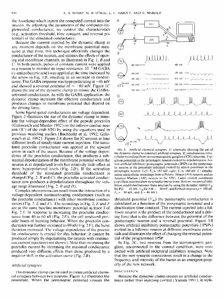
injection of digitally synthesized synaptic conductance
TRANSCRIPT
Journal of Neuroscience Methods, 49 (1993) 157-165 157
© 1993 Elsevier Science Publishers B,V. All rights reserved 0165-0270/93/$06.00
NSM 01535
Injection of digitally synthesized synaptic conductance transients
to measure the integrative properties of neurons
H u g h P.C. Rob inson a and Nobufumi Kawai b
a Physiological Laboratory, University of Cambridge, Downing St., Cambridge, CB2 3EG (UK) and ~' Department of Physiology,
Jichi Medical School, Minamikawachi, Tochigi-ken 329-04 (Japan)
(Received 5 January 1993)
(Revised version received 8 April 1993)
(Accepted 14 April 1993)
Key words: Conductance injection; Synaptic conductance; Current-clamp; Hippocampal neuron
A novel technique was developed for injecting a time-varying conductance into a neuron, to allow quantitative measurement of
the processing of synaptic inputs. In current-clamp recording mode, the membrane potential was sampled continuously and used to
calculate and update the level of injected current within 60 ~zs, using a real-time computer, so as to mimic the electrical effect of a
given conductance transient. Cellular responses to synthetic conductance transients modelled on the fast (non-N-methyl-l~-aspar-
tare) phase of the glutarnatergic postsynaptic potential were measured in cultured rat hippocampal neurons.
Introduction
The inputs to a neuron consist of focal tran-
sients of membrane conductance at the postsy-
naptic sites, whose magnitude is essentially inde-
pendent of the postsynaptic response. The output
of a neuron is represented by the membrane
potential in the cell body or axon. However, the
relationship between transient conductance in-
puts and the resulting trajectory of membrane
potential has never been directly measured. The
current lsyn(t) flowing through the synaptic con-
ductance at a postsynaptic site depends on the
postsynaptic membrane potential V(t), according
to the equation
l~yn(t) = g ( t ) ( E r e v - V ( t ) ) (1)
Correspondence: Hugh P.C. Robinson, Physiological Labora-
tory, University of Cambridge, Downing St., Cambridge, CB2
3EG, UK. Tel.: 0223-333835.
where g(t) is the time-varying conductance and
Ere ~, is the reversal potential for the conductance.
In particular, for a given g(t), the current is
diminished to zero and then reversed as the
membrane is polarized through Er~ v. V(t) de-
pends upon the complexities of current flow
throughout the whole neuron, including l~yn(t),
active voltage-dependent currents, and currents
at other synaptic sites. The interdependence of
Isyn(t) and V(t) is such that, even for a passive
membrane consisting of a linear resistance and
capacitance in parallel, the conductance input-
voltage output relationship is non-linear. Further-
more, injection of a fixed-current transient, with-
out feedback of the membrane potential cannot,
in general, reproduce the effect of a conductance
input. Nevertheless, current injection has been
the main technique employed to gain experimen-
tal insight into the integrative action of mam-
malian neurons (for a review, see Llinfis, 1988).
The assumption that synaptic inputs are pre-
scribed current transients also greatly simplifies
the problem of calculating voltage responses for
15~
passive membrane, which becomes linear (Rail,
1977). However, as seen from Eqn. 1, this ap-
proach can be valid only when the voltage is so
far from the equilibrium potential that it can be
considered constant. It cannot describe even ap-
proximately the action of an inhibitory synapse as
the membrane potential ranges on both sides of
the reversal potential. The analytical theory of
conductance inputs for passive membrane is ex-
tremely difficult, and has not so far provided
general solutions analogous to those for current
inputs (MacGregor, 1968; Barrett and Crill, 1974;
Poggio and Torre, 1978; Tuckwell, 1988). Numer-
ical modelling has been the most profitable ap-
proach to defining the role of conductance inputs
(e.g., Koch et al., 1983; Turner, 1984; Wathey et
al., 1992), but relies upon still fragmentary knowl-
edge of the properties and distributions of neu-
ronal membrane conductances.
In order to characterize the integrative action
of neurons experimentally, it is necessary to mea-
sure the output V(t) in response to exactly speci-
fied transients of conductance at defined loca-
tions in the cell, which have the same kinetics and
reversal potential as natural synaptic conductance
transients. Neither voltage-clamp nor current-
clamp techniques provide a direct approach to
this problem. Voltage-clamp recording, in mea-
suring g(t), necessarily cancels V(t), while cur-
rent-clamp recording measures V(t) but not g(t). Here, we present a technique for stimulating a
neuron, during current-clamp recording, with a
current that follows Eqn. 1. This has the effect of
simulating a known transient conductance, and
allows the g(t)/V(t) relationship to be measured
explicitly. In this technique, the injected current
level is continuously updated according to Eqn. 1
by a real-time computer, using the instantaneous
measurement of the membrane potential, a pre-
specified constant reversal potential and a time
template for the conductance derived from volt-
age-clamp recordings of synaptic currents. The
method was applied in small cultured hippocam-
pal neurons to demonstrate the processing of
conductance transients mimicking the natural fast
excitatory and inhibitory postsynaptic conduc-
tances. A preliminary report of this work has
appeared elsewhere (Robinson, 1991).
Methods
Dissociated hippocampal neurons were cul-
tured from neonatal rats as described previously
(Robinson et al., 1991), and maintained for 1-2
weeks before experiments. Very small (diameter
< 12 ~m), rounded neurons with few processes
were selected for recording. To record natural
spontaneous postsynaptic currents, pipettes were
filled with the solution: 141 mM CsCI, 5 mM
EGTA, 0.5 mM CaC12, 10 mM HEPES/Na (pH
7.2). The bath solution contained: 150 mM NaCI,
2.8 mM KC1, 0.5 mM CaCI2, 10 mM HEPES/Na
(pH 7.2). For conductance injection, the pipette
solution consisted of: 141 mM KCI, 0.5 mM
CaCl~, 5 mM EGTA, 10 mM HEPES/Na (pH
7.2), and the bath solution of 142 mM NaC1, 2.8
mM KCI, 2 mM CaCI2, 1 mM MgC1 z, I0 mM
HEPES/Na, 5 mM o-glucose (pH 7.2) to which
were added 10 /zM CNQX (Tocris Neuramin,
Buckhurst Hill, UK), 30 t~M APV (Tocris), and
30 ~M strychnine (Tokyo Kasei Kogyo Co.,
Tokyo, Japan). All experiments were at room
temperature (23-25°C).
Conductance injection was carried out as fol-
lows. Whole-cell recordings (Hamill et al., 1981)
were established using a whole-cell patch-clamp
amplifier (Axopatch l-D, Axon Instruments, Fos-
ter City, CA) in current-clamp mode. In voltage-
clamp mode, the capacitive charging time con-
stant was less than 40 Izs. The real-time calcula-
tion of the current command signal was per-
formed by a dedicated analog processing board
(AS-l, Cambridge Research Systems, Rochester,
Kent, UK), which included a 12 MHz 80186 pro-
cessor, clocks, 512 kbytes memory, and 12-bit
analog-to-digital converters (ADC) and digital-
to-analog converters (DAC). The settling time
constant of the DACs was approximately 1 ~s.
DAC update and ADC sampling were exactly
synchronized using the direct memory access
channels of the processor. The membrane poten-
tial signal was sampled after passage through an
anti-aliasing filter (5 kHz, -3dB Bessel charac-
teristic). Conductance templates were stored in
memory at a resolution of 16 bits, and the multi-
plication, at each time step, by the result of
subtracting the voltage from the reversal poten-
159
tial, was carried out to 28-bit intermediate preci-
sion. The 12 most significant bits were written to
the DAC connected to the current command
input of the amplifier. The arithmetic in each
cycle lasted only 4.58 p.s, with the remaining time
used for handling timers, transferring samples to
memory, and update of loop variables. The small-
est attainable fit was 58.8 /zs, which was used
throughout.
Results
Whole-cell voltage-clamp recording from small
neurons cultured from rat hippocampus revealed
2 types of spontaneous synaptic current. A gluta-
matergic excitatory postsynaptic current (e.p.s.c)
a
(Fig. la), comprised a fast, non-N-methyl-D-
aspartate (non-NMDA) receptor-mediated com-
ponent with a decay time constant (r) of 1.5-4
ms (Fig. la), and a slow, NMDA receptor-media-
ted phase with a decay r of 80-150 ms (Eqn. 3)
(Fig. lb), in which single channel openings could
clearly be resolved in the whole-cell current (see
Robinson et al., 1991). Similar biphasic gluta-
matergic e.p.s.c.s have been described by Hestrin
et al. (1988), Forsythe and Westbrook (1988),
Bekkers and Stevens (1989) and Keller et al.
(1991), and appear to be a general feature of
most mammalian central neurons. An inhibitory
postsynaptic current (i.p.s.c.) decayed monoexpo-
nentially with a r of 30-40 ms (Fig. lc), as
described by Segal and Barker (1984).
We found that both the fast phase of the
b c
" x2 = 2.23 xl = 1.1l zz = 38.12
- , • , , . : i C . . . . . ',." .. ... • ~. ' , . . . . : ='~
V " "~2 = 1.68
~:':.-.:...
i = 0.45
"t:2 = 35.6
3 . " , " ' ¢ ~ ¢ ' ~ ~ i " ' " " " ' " " " ~ ~ r ~ : . . . . . . .
x2 = 2.47 V ~ ~ 36.47
• , ~ . . . . . . . . . . . . . . . . . . . . . ~ . . : : . . . . : . . _ = . . = . ¢ . 4 ~ . ~ . ; . . . ~ : ~ = ~ . : ~ : : ~ , . _ j 30 pA
__J 20 pA i 84 20 ms
2ms " ~ ~ 5,50pA
50 ms Fig. 1. F i t t ing of the k ine t ics of s p o n t a n e o u s synapt ic cu r ren t s in ra t h i p p o c a m p a l neurons , a: 3 fast, n o n - N M D A e.p.s.c.s, se lec ted
for the absence of ear ly ensu ing N M D A c h a n n e l open ings . Leas t - squa res fits to the equa t ion : I( t )=K ( 1 - e x p ( - t / ~ - 0 )
exp( - t / r 2) (Ere v - V) are s u p e r i m p o s e d wi th the va lues of r I and -r 2 ind ica ted . V = - 7 5 mV, b a n d w i d t h D C - 1 0 kHz
( app rox ima te b a n d w i d t h of ampl i f i e r and record ing system, r e s a m p l e d at 25 kHz). b (3 top traces): s p o n t a n e o u s e.p.s.c.s, wi th the
charac te r i s t i c b iphas ic a p p e a r a n c e of the n o n - N M D A ( f a s t ) / N M D A (slow, noisy) g l u t a m a t e r g i c e.p.s.c. Single channe l open ings
may be seen in the N M D A phase . ( lower trace): e n s e m b l e ave rage of 30 a l igned s p o n t a n e o u s e.p.s.c.s, wi th a s ingle exponen t i a l fit
of "r = 84 ms to the slow ( N M D A ) phase. V = - 75 mV, b a n d w i d t h D C - 2 kHz (Gauss ian) . c: 3 i.p.s.c.s, wi th fits as in (a). V = - 70
rnV, b a n d w i d t h D C - 10 kHz, as in (a).

l f~O
e.p.s.c and i.p.s.c were well fitted by a product of
2 exponential functions, so that the underlying
conductance transients, g(t), could be written as
( ' ) , g ( t ) = K . 1 - e x p - - . e x p - - (2)
TI "/'2
Assuming that g(t) is independent of V, the
current l(t) flowing at the synaptic site should be
given by substituting Eqn. 2 for g(t) in Eqn. 1.
This assumption is reasonable for the fast gluta-
mate e.p.s.c., which shows only a 10% change in
decay r over the range - 100 mV to 0 mV (Keller
et al., 1991). To inject conductance transients, we
used the discrete time approximation to Eqn. 1:
ll+,~t=g, ( E r e v - Vt), to determine the com-
manded current in current-clamp recording mode.
At time t + 6t, the commanded current level was
updated to the product of the conductance value
in the template for time t and the result of
subtraction of the potential measured at time t
from the reversal potential Ere v. This feedback
loop has the effect of creating a current source
which well approximates the effect of the synaptic
conductance g(t) when ~t is small. In the present
experiments, 3t was fixed at 58.8/zs. To confirm
the accuracy of the conductance synthesis, we
injected conductance transients of the form speci-
fied by Eqn. 2 with r I = 2 ms and r 2 = 15 ms,
into a model passive cell. The resulting voltage
response was very close to the expected response,
calculated by integrating the differential equation
for the circuit numerically (Fig. 2).
Fig. 3a shows the injection of a conductance
transient modelled on that of the fast e.p.s.c, with
a reversal potential of 0 mV. For all conductance
injection experiments, the pipette contained a
predominantly potassium chloride solution (see
Materials and methods), while CNQX, APV, strychnine and magnesium were added to the
bath. The intention was to block natural synaptic
events without impairing the function of voltage-
dependent channels which react to synaptic con-
ductance inputs under physiological conditions; it
should be noted that strychnine is an effective
blocker not only of glycine receptors, but also of
GABA a receptors at the concentration used (30
/zM) (Shirasaki et al., 1991). The measured po-
tential is shown superimposed on the expected
i' J
E~e~ .................. ~ .... ....... i • 1
V(t) . . / ~ 50 mV
300 pS
20 m s
g(t) Fig. 2. Conductance injection in a model ceil. g(t) was speci-
fied by Eqn. 2, with K = 9 0 0 pS, r 1 = 2 ms, r z = 1 5 ms,
Ere v = 200 mV (indicated by a dotted line). The parameters of
the model cell are shown in the inset. The solid V(t) trace
shows the measured response (averag e of 10 trials), while the
dashed trace shows the expected response calculated by nu-
merical integration (Euler integration, time step 1 ~s).
passive response calculated by numerical integra-
tion, using the values for cell input resistance and
capacitance determined by small hyperpolarizing
current steps from rest (see Fig. 3a inset). This
reveals a non-linear active response due to volt-
age-dependent inward current. The injected cur-
rent is the product of the time-varying potential
driving force and the conductance template, and
reaches its peak approximately 0.5 ms before the
peak of conductance, then falls biphasicaUy be-
fore rising again in a small, late peak. Thus,
current of a similar time course should flow
through the non-NMDA channels during a
synaptic potential in the unclamped active mem-
brane. In Fig. 3b, a conductance template based
on the slower kinetics of an inhibitory postsynap-
tic event, and a reversal potential of - 6 0 mV,
was injected repeatedly as the membrane poten-
tial was changed between - 100 and - 25 mV by
background current injection, illustrating the re-
versal of the artificially induced transients.
The relationship between the amplitude of a
fast glutamate-like conductance transient and the
depolarization was investigated by varying K (Fig.
4a). At potentials near to rest, the form of re-
sponses is as expected for a passive membrane,
and the peak of each response showed the grad-
ual sublinearity expected as the driving force was
reduced by approaching Ere v. Around - 3 5 mV,
a graded action potential appeared, whose peak
becomes higher and earlier with increasing K.
Graded action potentials are also observed in
small cultured hippocampal neurons when stimu-
lated by conventional current injection (Johann-
son et al., 1992). From the plot of the peak of
V( t ) against K (Fig. 4b), the resistance of this cell
appears to be higher in the depolarizing direction
than measured at rest, possibly due to the pres-
ence of inward rectifier K ÷ channels. Similar
peak V(t ) - K relationships were found in 3 other
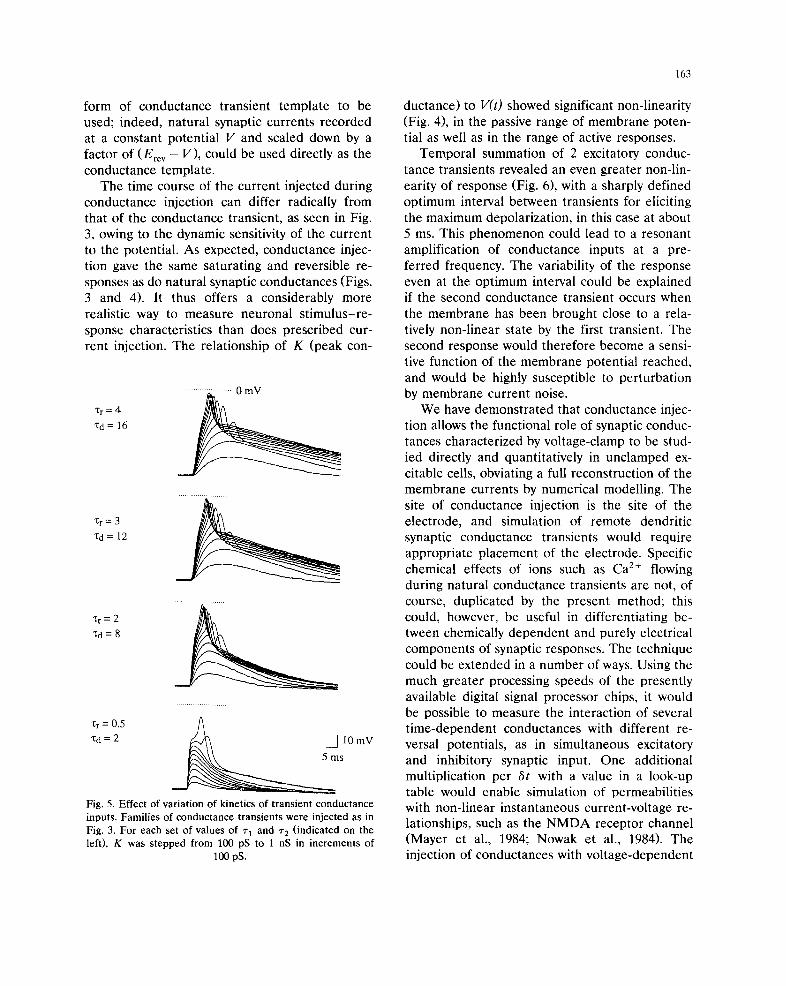
neurons. Fig. 5 shows the effect of varying the
kinetics of the conductance transient, in the same
neuron as in Fig. 4. When the 2 time constants in
Eqn. 2 were multiplied by the same scaling factor,
161
(scaling in time only, without change in the peak
conductance), the maximum depolarization at
each value of K increased markedly as the kinet-
ics were scaled from ~'~ = 0.5, r 2 = 2 ms, up to
r 1 = 3, r 2 = 12 ms, but showed comparitively little
further change at ~1 = 4, ~2 = 16 ms.
Temporal summation was investigated in 1
neuron by varying the separation between 2 iden-
tical excitatory conductance transients (Fig. 6).
For K = 300 pS, separations of 10 ms and over
were subthreshold for eliciting an action poten-
tial. At smaller separations, however, a late ac-
tion potential was elicited, which increased in
amplitude to a maximum at 5 ms separation,
declining sharply again as the separation was
decreased further, though the peak value of in-
jected conductance continued to increase. Thus,
there was a sharply defined optimal separation of
5 ms. The temporal summation experiments
a
0 mV ............... ~ , / ~ " 10 mV
Voltage Response ~ lo m] 20 my
Passive Membrane
Current [ 10 pA
b
-60 mV -
~ 10 mV
100 pS
20 ms
f x
Conductance ~ I 10o pS
10 ms
Fig. 3. Conductance injection, a (top trace): injection of a conductance transient modelled on the fast e.p.s.c., with K = 1 nS, ~'1 = 1,
~'e = 4, Ere v = 0 mV; (top trace): measured voltage response superimposed on the expected response (calculated by numerical
integration) if the cell comprised a 3.79 GO resistor and a 2.2 pF capacitor in parallel; values measured using 1.4 pA
hyperpolarizing current steps from rest (inset). (middle trace): the (commanded) current injected during the transient, determined
by the equation: I t + ~ = gt (Erev - Vt)" 6t was 58.8 p,s. b: voltage responses to injection of a gt template modelled on the i.p.s.c.
(bottom trace): K = 500 pS, ~'i = 1 ms, r 2 = 30 ms, Ere v = - 6 0 mV. The resting membrane potential was varied for each different
voltage response by injection of an additional constant background current. Cell resistance, 3.5 GO; capacitance, 1.71 pF.

162
a 0 mV
10mV
b
-I0 -, f - "¢
-20 -- /
-30 - /
-40 - J ~ f -
-60
-70 ' -v ~ - - , j
0 200 400 600 800 1000 1200
Conductance (pS)
100 pS
10 ms
Fig. 4. Non-linear summation of excitatory conductance inputs. A family of conductance transients modelled on that underlying the
fast glutamatergic e . p . s . c . ( ' / '1 = 1 ms, T 2 = 4 ms, Ere v = 0 mV)was injected into a neuron with a resting potential of - 6 5 inV. Each
injection was separated by 10 s for recovery, and K was stepped from 50 pS to 1.1 nS in steps of 50 pS. a: measured potential
responses (top) and conductance transients (bottom). b: peak membrane potential during each transient as a function of the K
scaling value. Triangles: measured values. Solid line: computed responses for passive cell (R = 3.79 GO, C = 2.2 pF).
showed a much higher variation in spike ampli-
tude when compared to injection of a single con-
ductance transient eliciting the same maximum
response (not shown), and the greatest variation
was at the optimal separation.
Discussion
The accuracy of the present method depends
upon sufficiently fast current injection by the
current-clamp amplifier, such that the com-
manded current is not filtered significantly, and
on the delay with which the current command is
updated by the real-time computer, /~t, which
should be short enough not to give rise to aliasing
of the voltage transient. The close agreement of
the time course and amplitude of voltage tran-
sients with the calculated transients in the model
cell (Fig. 2), implies that neither source of error
was significant for passive responses to the syn-
thetic synaptic conductance transients. In the
neurons examined, the 17 kHz sampling rate used
was sufficient not to alias measured active re-
sponses, and current-clamp showed a fast time
constant of about 50 gs. However, for cells with
much larger active currents, for example at a
later stage of development, it would be important
to use a conventional amplifier designed for
high-speed current-clamp with a voltage follower
at the input stage, instead of a patch-clamp am-
plifier, and also to decrease 8t further to prevent
aliasing of the sampled potential.
We used the product of 2 exponentials (Eqn.
2) to describe the form of synaptic conductance
changes, and showed that such a function pro-
vides good fits to natural synaptic inhibitory and
fast excitatory currents in these cells. When the
ratio rl : % is large, this function becomes close
to the difference (or convolution) of 2 exponen-
tials, which may be expected theoretically if
transmitter release is effectively pulsatile and
synaptic channels have a single open and a single
closed state. However, the method permits any
form of conductance transient template to be
used; indeed, natural synaptic currents recorded
at a constant potential V and scaled down by a
factor of (Ere v - V), could be used directly as the
conductance template.
The time course of the current injected during
conductance injection can differ radically from
that of the conductance transient, as seen in Fig.
3, owing to the dynamic sensitivity of the current
to the potential. As expected, conductance injec-
tion gave the same saturating and reversible re-
sponses as do natural synaptic conductances (Figs.
3 and 4). It thus offers a considerably more
realistic way to measure neuronal stimulus-re-
sponse characteristics than does prescribed cur-
rent injection. The relationship of K (peak con-
1:r=4
Xd= 16
"Or=3
'l:d= 12
Xr= 2
~d=8
• ~ = 0.5 A Xd = 2 ~ d ~ ~ I0 mV
~ m s
Fig. 5. Effect of variation of kinetics of transient conductance
inputs. Families of conductance transients were injected as in
Fig. 3. For each set of values of r~ and ~'2 (indicated on the
left), K was stepped from 100 pS to 1 nS in increments of
100 pS.
163
ductance) to V(t) showed significant non-linearity
(Fig. 4), in the passive range of membrane poten-
tial as well as in the range of active responses.
Temporal summation of 2 excitatory conduc-
tance transients revealed an even greater non-lin-
earity of response (Fig. 6), with a sharply defined
optimum interval between transients for eliciting
the maximum depolarization, in this case at about
5 ms. This phenomenon could lead to a resonant
amplification of conductance inputs at a pre-
ferred frequency. The variability of the response
even at the optimum interval could be explained
if the second conductance transient occurs when
the membrane has been brought close to a rela-
tively non-linear state by the first transient. The
second response would therefore become a sensi-
tive function of the membrane potential reached,
and would be highly susceptible to perturbation
by membrane current noise.
We have demonstrated that conductance injec-
tion allows the functional role of synaptic conduc-
tances characterized by voltage-clamp to be stud-
ied directly and quantitatively in unclamped ex-
citable cells, obviating a full reconstruction of the
membrane currents by numerical modelling. The
site of conductance injection is the site of the
electrode, and simulation of remote dendritic
synaptic conductance transients would require
appropriate placement of the electrode. Specific
chemical effects of ions such as Ca 2+ flowing
during natural conductance transients are not, of
course, duplicated by the present method; this
could, however, be useful in differentiating be-
tween chemically dependent and purely electrical
components of synaptic responses. The technique
could be extended in a number of ways. Using the
much greater processing speeds of the presently
available digital signal processor chips, it would
be possible to measure the interaction of several
t ime-dependent conductances with different re-
versal potentials, as in simultaneous excitatory
and inhibitory synaptic input. One additional
multiplication per 8t with a value in a look-up
table would enable simulation of permeabilities
with non-linear instantaneous current-voltage re-
lationships, such as the NMDA receptor channel
(Mayer et al., 1984; Nowak et al., 1984). The
injection of conductances with voltage-dependent

164
a
10 ms 5 ms ~
4 ms 8 m s ~
7ms 2ms
b
>
o
-10
20
-30
-40
-50 I I I ~ F
2 4 6 8 10
Separation (msec)
/2®ps
Fig. 6. Temporal summation of excitatory conductance inputs, a: the sum of 2 identical coL~cluctance transients (K = 300 pS, ~'1 = 1
ms, r 2 = 4 ms, Ere v = 0 mV) offset by various intervals between 0 and 10 ms was iNected into a neuron. Three to 10 records were
acquired at each interval, with 10 s between trials, b: the peak membrane potential reached was plotted as a function of the
separation between the summed conductance transients (open triangles). Solid lines indicate the envelope of the response, which
showed a marked optimum at 5 ms separation between conductance transients. Filled squares: computed response of the passive
circuit of the neuron.
kinetics described by the conventional model
(Hodgkin and Huxley, 1952) would be feasible if
the rate equations could be integrated accurately
in real time. Injection of negative conductance
could be used to cancel or titrate intrinsic con-
ductances.
Acknowledgements
We thank Prof. Vincent Torre, Universitfi di
Genova, for his comments. This work was sup-
ported by a grant from the Japanese Ministry of
Science and Culture, No. 63060006.
References
Barrett, J.N. and Crill, W.E. (1974) Influence of dendritic
location and membrane properties on the effectiveness of
synapses on cat motoneurones. J. Physiol., 239: 325-345.
Bekkers, J.M. and Stevens, C.F. (1989) NMDA and non-
NMDA receptors are colocalized at individual excitatory
synapses in cultured rat hippocampus. Nature, 341: 230-
233.
Forsythe, I.D. and Westbrook, G.L. (1988) Slow excitatory
postsynaptic currents mediated by N-methyl-D-aspartate
receptors on cultured mouse central neurones: J. Physiol.
(Lond.), 396: 515-533.
Hamill, O.P., Marty, A., Neher, E., Sakmann, B. and Sig-
worth, F.L (1981) Improved patch-clamp techniques for
high-resolution current recording from cells and cell-free
membrane patches. Pfliigers Arch., 391: 85-100.
Hestrin, S., Nicoll, R.A., Perkel, D.J. and Sah, P. (1990)
Analysis of excitatory synaptic action in pyramidal cells
using whole-cell recording from rat hippocampal slices. J.
Physiol. (Lond.), 422:203-225
Hodgkin, A.L. and Huxley, A.F. (1952) A quantitative de-
scription of membrane current and its application to con-
duction and excitation in nerve. J. Physiol. (Lond.), 117:
500-544.
Johansson, S., Friedman, W. and .;krhem, P. (1992) Impulses
and resting membrane properties of small cultured rat
hippocampal neurons, J. Physiol. (Lond.), 445: t29-140.
Llin~is, R.R. (1988) The intrinsic electrophysiological proper-
ties of mammalian neurons: insights into central nervous
system function. Science, 242: 1654-1664.
Keller, B.U., Konnerth, A. and Yaari, Y. (1991) Patch clamp
analysis of excitatory synaptic currents in granule cells of
rat hippocampus. J. Physiol. (Lond.), 435: 275-293.
Koch, C., Poggio, T. and Torre, V. (1983) Nonlinear interac-
tions in a dendritic tree: localization, timing, and role in
information processing. Proc. Natl. Acad. Sci. (USA), 80:
2799-2802.
MacGregor, R.J. (1968) A model for responses to activation
by axodendritic synapses. Biophys. J., 8: 305-318.
Mayer, M.L., Westbrook, G.L. and Guthrie, P.B. (1984) Volt-
age-dependent block by Mg 2÷ of NMDA responses in
spinal cord neurones. Nature, 309: 261-263.
Nowak, L., Bregestovski, P., Ascher, P., Herbet, A. and
Prochiantz, A. (1984) Magnesium gates glutamate-activated
channels in mouse central neurons. Nature, 307: 462-465.
Poggio, T. and Torre, V. (1978) A new approach to synaptic
interactions. In: R. Heim and G. Palm (Eds.), Approaches
to complex systems, Springer, Berlin, pp. 89-115.
Rail, W. (1977) Core conductor theory and cable properties of
neurons. In: E.R. Kandel (Ed.), Handbook of Physiology,
The Nervous System, Vol. 1, Section 1, Am. Physiol. Soc.,
Bethesda, MD.
165
Robinson, H.P.C. (1991) Kinetics of synaptic conductances in
mammalian central neurons. Neurosci. Res., Suppl. 16: VI.
Robinson, H.P.C., Sahara, Y. and Kawai, N. (1991) Nonsta-
tionary fluctuation analysis and direct resolution of single
channel currents at postsynaptic sites. Biophys. J., 59:
295-304.
Segal, M. and Barker, J.L. (1984) Rat hippocampal neurons in
culture: voltage-clamp analysis of inhibitory synaptic con-
nections. J. Neurophysiol., 52: 469-487.
Shirasaki, T., Klee, M.R., Nakaye, T. and Akaike, N. (1991)
Differential blockade of bicuculline and strychnine on
GABA- and glycine-induced responses in dissociated rat
hippocampal pyramidal cells. Brain Res., 561: 77-83.
Tuckwell, H.C. (1988) Introduction to Theoretical Neurobiol-
ogy, Vol. 2, Nonlinear and Stochastic Theories, Cambridge
University Press, Cambridge, UK, 265 pp.
Turner, D.A. (1984) Conductance transients onto dendritic
spines in a segmental cable model of hippocampal neu-
rons. Biophys. J., 46: 85-96.
Wathey, J.C., Lytton, W.W., Jester, J.M. and Sejnowski, T.J.
(1992) Computer simulations of EPSP-spike (E-S) potenti-
ation in hippocampal CA1 pyramidal cells. J. Neurosci..
12: 607-618.
COMPUTATIONAL NEUROSCIENCE NEUROREPORT
0959-4965 & Lippincott Williams & Wilkins Vol 11 No 3 28 February 2000 563
Interacting biological and electronic neurons
generate realistic oscillatory rhythms
Attila SzuÍcs,CA Pablo Varona, Alexander R. Volkovskii, Henry D. I. Abarbanel,1 Mikhail I. Rabinovich
and Allen I. Selverston
Institute for Nonlinear Science, University of California San Diego, 9500 Gilman Drive, La Jolla, CA 92093-0402; 1Department of
Physics and Marine Physical Laboratory, Scripps Institution of Oceanography, University of California San Diego, La Jolla, CA
92093-0402, USA
CACorresponding Author
Received 22 October 1999; accepted 9 December 1999
Acknowledgements: Partial support for this work comes from the US Department of Energy, Of®ce of Basic Energy Sciences,Division of Engineering and Geosciences, under grant DE-FG03-90ER14138 and DE-FG03-96ER14592.
Small assemblies of neurons such as central pattern generators(CPG) are known to express regular oscillatory ®ring patternscomprising bursts of action potentials. In contrast, individualCPG neurons isolated from the remainder of the network cangenerate irregular ®ring patterns. In our study of cooperativebehavior in CPGs we developed an analog electronic neuron(EN) that reproduces ®ring patterns observed in lobsterpyloric CPG neurons. Using a tuneable arti®cial synapse we
connected the EN bidirectionally to neurons of this CPG. Wefound that the periodic bursting oscillation of this mixedassembly depends on the strength and sign of the electricalcoupling. Working with identi®ed, isolated pyloric CPG neu-rons whose network rhythms were impaired, the EN/biologicalnetwork restored the characteristic CPG rhythm both whenthe EN oscillations are regular and when they are irregular.NeuroReport 11:563±569 & 2000 Lippincott Williams & Wilkins.
Key words: Electronic neuron; Electronic synapse; Oscillatory rhythm; Pyloric neurons; Regularization; Synchronization
INTRODUCTIONCentral pattern generators (CPGs) are widely studiedsystems of rhythm generation in small neuron assemblies[1]. The regularity and stationarity of the oscillatory pat-terns generated by a small number of interacting neuronsis noteworthy, especially in light of evidence that suchnetworks are composed of individual neurons which canoscillate chaotically when observed in isolation. Indeed,CPG neurons with their synaptic inputs blocked have beenshown to express chaotic ®ring patterns [2±6]. Regularrhythm generating neurons called pacemakers are com-monly believed to be fundamental parts of the CPGs,initiating the main oscillation [7]. A pacemaker neuron orgroup may be required to synchronize all other neuronsand control joint rhythms because of the differences in theproperties of individual neurons.
The stomatogastric ganglion (STG) of crustaceans is awell understood nervous system [8]. It contains the pyloricCPG that generates a highly regular and repetitive motorpattern resulting from interactions between 14 neurons. Inthis system the anterior burster (AB) neuron is one of themain pacemaker elements, having a central role in organiz-ing the rhythm. The two electrically coupled pyloric dilator(PD) neurons ®re in-phase with the AB forming a triplet ofpacemaker neurons. The robustness and uniformity of the
oscillation initiated by AB makes it dif®cult to manipulateor interact with the rhythm and investigate the role ofindividually irregular PDs in the pattern generation.
Based on our non-linear analysis of experimental datafrom isolated pyloric neurons, we have developed a simpleanalog electronic model of CPG neurons capable of repro-ducing the observed ®ring patterns. The `electronic neuron'(EN) was connected to the PD cells using an arti®cialsynapse, thus forming a mixed circuit. This approachallowed us to dynamically interact with the biologicalneurons rather than stimulating them using response-independent current commands. In this fashion we haveshown that the regular, natural rhythm of the PD in theintact network is restored when interacting with the ENs.This occurs both when the EN is behaving regularly andwhen it is set into a state of chaotic oscillations.
MATERIALS AND METHODSPreparation and electrophysiology: The stomatogastricnervous system (STNS) of the spiny lobster Panulirusinterruptus L. was dissected and prepared as describedearlier [9]. Brie¯y, the STG, the oesophageal ganglion andthe two comissural ganglia with the interconnecting nerveswere separated from the stomach and pinned in a Sylgard-lined Petri dish containing standard Panulirus physiologi-
cal saline [3]. The STG was perfused separately from therest of the STNS using a vaseline chamber. Picrotoxin(PTX; 7.5 ìM) was used to block glutamatergic synaptictransmission and isolating the pyloric pacemaker groupfrom other pyloric neurons. Nerve cells were identi®ed bycomparing intracellular signals with extracellular burstpatterns monitored simultaneously from output motornerves. Partial isolation of the two PD neurons wasperformed by photoinactivating the presynaptic AB neuron[10]. The membrane potential of the cells was measuredwith Neuroprobe 1600 current-clamp ampli®ers (AM-Sys-tems). The PD neuron which we connected to the electronicneuron was impaled with two microelelectrodes ®lled with3M KCl and with resistances of 10-15MÙ. One of thesewas used to monitor the membrane potential, while theother served as a current passing electrode. This methodallowed us to avoid any problems arising from imperfectbridge balancing or non-linearities of the current passingelectrode. A total of 198 trials were performed on ninepreparations.
Electronic neuron and synapse: We have designed andbuilt a three degree of freedom analog electronic circuitrealization of a mathematical model of bursting neurons.The model was suggested by the work of Hindmarsh andRose [11]. It uses a polynomial representation of thedependence of ion currents on the membrane potentialaccording to the following differential equations:
_x � 4y�3x2
2ÿ
x3
4ÿ 2z� å, _y �
1
2ÿ5x2
8ÿ y,
_z � ì(ÿz� 2x� 6:4)
where x is the membrane potential, y and z are `fast' and`slow' internal variables, å represents the external currents,and ì is the time constant of the slow variable. Both å andì are tuneable parameters. The HR model captures themost important ®ring/bursting modes of real CPG neurons[12]. This model, however, generates spikes with too largean amplitude relative to the depth of interburst hyperpo-larization. To make this ratio more realistic we used anadditional nonlinear ampli®er which reshaped the outputof the HR model neuron and made the membrane potentialoscillation more similar to that of bursting pyloric neurons(compare Fig. 1A, PD trace with Fig. 2A, EN trace). TheEN, connected bidirectionally to the PD, was able toreceive and process incoming signals in the same fashionas biological neurons receiving synaptic inputs. This func-tionality came from an additional electronic circuit simulat-ing an electrotonic synapse. The potential differencebetween the EN and the biological neuron was measured,and a current signal proportional to the difference wasgenerated. This current was fed back to the EN andconnected to the current input of the intracellular ampli®erwith opposite polarity. The amplitude and sign of thecurrent depended on the actual potential difference and aconductance parameter, set by the experimenter.
Data acquisition and analysis: The extra- and intracellu-lar signals were acquired at 10 kS/s rate by the Axoscope7.0 program running on a PC. Raw membrane potentialdata were visually inspected, and detailed quantitative
analysis was performed using spike arrival times. The timederivative of the intracellular time series was used to detectspike events, and interspike-interval (ISI) sequences wereconstructed for each train. First-order return maps of theISIs were used as a graphical tool characterizing the overalldynamics and the regularity of the ®ring patterns. Thespike-density function (SDF) [13] was used to characterizemodulations of the ®ring patterns and to detect correla-tions between simultaneous spike trains. The SDF tech-nique allowed us to obtain ®ring rate as a continuousfunction of the elapsed time [14]. An SDF was constructedby convolving the time of each spike event with aGaussian-function (kernel) of unit area and ®xed half-width, typically 0.2 s here. The Fourier transform of thespike density functions was used to detect any periodicities
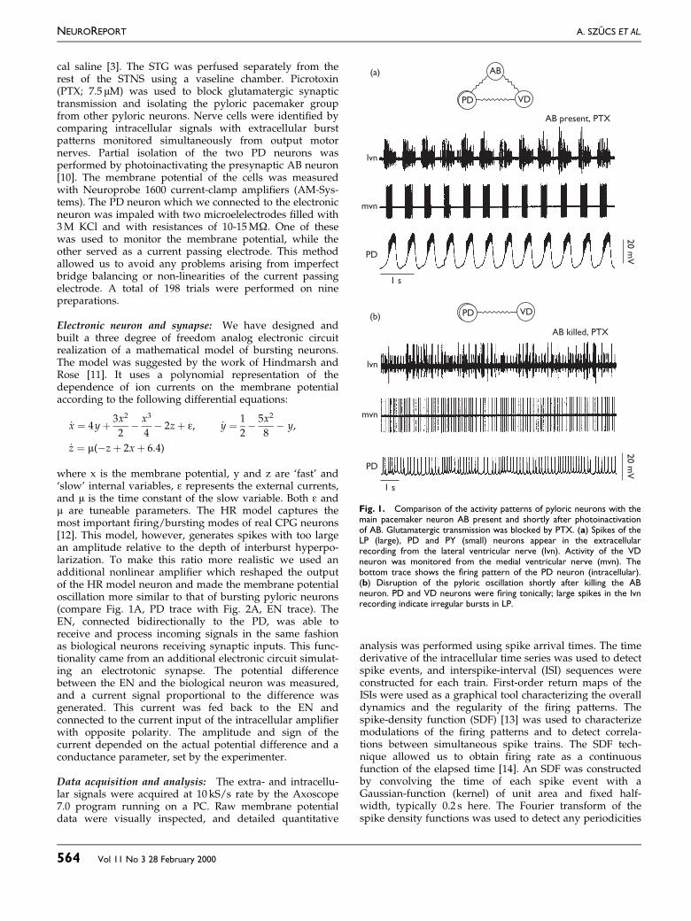
Fig. 1. Comparison of the activity patterns of pyloric neurons with themain pacemaker neuron AB present and shortly after photoinactivationof AB. Glutamatergic transmission was blocked by PTX. (a) Spikes of theLP (large), PD and PY (small) neurons appear in the extracellularrecording from the lateral ventricular nerve (lvn). Activity of the VDneuron was monitored from the medial ventricular nerve (mvn). Thebottom trace shows the ®ring pattern of the PD neuron (intracellular).(b) Disruption of the pyloric oscillation shortly after killing the ABneuron. PD and VD neurons were ®ring tonically; large spikes in the lvnrecording indicate irregular bursts in LP.
1 s
mvn
lvn
PD
20 m
V
(a)
AB present, PTX
AB
VDPD
PD VD
AB killed, PTX
(b)
mvn
lvn
PD
1 s
20 m
V
NEUROREPORT A. SZUÍ CS ET AL.
564 Vol 11 No 3 28 February 2000
in the ®ring patterns. Phase portraits were constructed byplotting the SDF of one neuron against that of the other.This graphical tool revealed cross-correlations betweenneurons recorded simultaneously.
RESULTSIntact and reduced pyloric network: The pyloric pace-maker group of the lobster consists of four electrotonicallycoupled neurons: AB, two PDs and the VD neuron [7].There are strong symmetrical connections between AB andthe PD neurons and weaker rectifying connections betweenthe AB and VD [15]. These nerve cells express a regularoscillatory pattern in the intact preparation (Fig. 1A).Picrotoxin, while blocking all glutamatergic synaptic inputsand functionally isolating the pacemaker network, hadlittle effect on the frequency or amplitude of the ongoingoscillation. In contrast, photoinactivation of the main pace-maker neuron AB led to complete disruption of the pyloricrhythm. Removal of AB led to cessation of the bursting
activity in PD neurons and in VD (Fig. 1B). Initially, afterphotoinactivation the PD expressed irregular spiking beha-vior that evolved after about 1 h into irregular bursting.The irregular bursting pattern remained for the lifetime ofthe preparation.
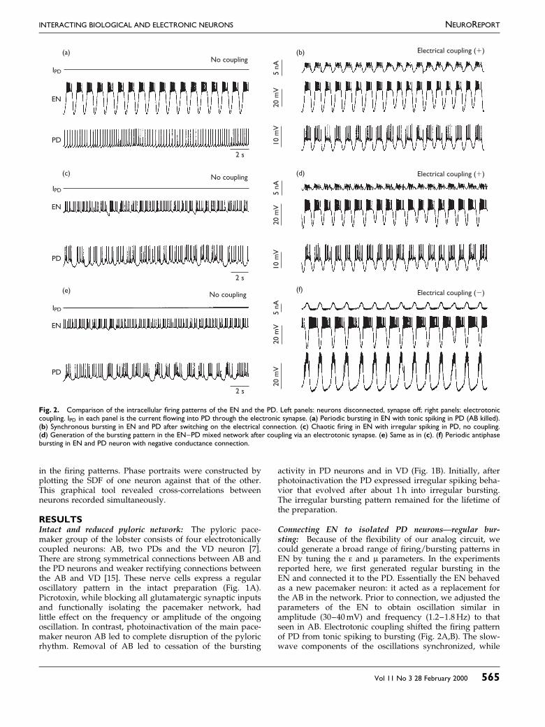
Connecting EN to isolated PD neuronsÐregular bur-sting: Because of the ¯exibility of our analog circuit, wecould generate a broad range of ®ring/bursting patterns inEN by tuning the å and ì parameters. In the experimentsreported here, we ®rst generated regular bursting in theEN and connected it to the PD. Essentially the EN behavedas a new pacemaker neuron: it acted as a replacement forthe AB in the network. Prior to connection, we adjusted theparameters of the EN to obtain oscillation similar inamplitude (30±40mV) and frequency (1.2±1.8Hz) to thatseen in AB. Electrotonic coupling shifted the ®ring patternof PD from tonic spiking to bursting (Fig. 2A,B). The slow-wave components of the oscillations synchronized, while
(a)No coupling
No coupling
2 s
EN
PD
IPD
(c)
IPD
EN
2 s
No coupling(e)
IPD
2 s
20 m
V20 m
V5 n
A10 m
V20 m
V5 n
A10 m
V20 m
V5 n
A
(b) Electrical coupling (1)
Electrical coupling (1)(d)
Electrical coupling (2)(f)
PD
EN
PD
Fig. 2. Comparison of the intracellular ®ring patterns of the EN and the PD. Left panels: neurons disconnected, synapse off; right panels: electrotoniccoupling. IPD in each panel is the current ¯owing into PD through the electronic synapse. (a) Periodic bursting in EN with tonic spiking in PD (AB killed).(b) Synchronous bursting in EN and PD after switching on the electrical connection. (c) Chaotic ®ring in EN with irregular spiking in PD, no coupling.(d) Generation of the bursting pattern in the EN±PD mixed network after coupling via an electrotonic synapse. (e) Same as in (c). (f) Periodic antiphasebursting in EN and PD neuron with negative conductance connection.
INTERACTING BIOLOGICAL AND ELECTRONIC NEURONS NEUROREPORT
Vol 11 No 3 28 February 2000 565
single spikes in EN and PD did not. The bursting patternof PD induced by the electrotonic coupling resembled thatin the intact pyloric pacemaker network. Monitoring activ-ity of the output nerve lvn showed that the burst pattern ofthe postsynaptic neuron LP was also synchronized withthe EN±PD pair, leading to a partial restoration of thepyloric rhythm. Inserting EN as a regular, periodic burst-ing element into the impaired neuronal network induced anew overall oscillation, quite similar to the original pyloricrhythm.
Connecting chaotic electronic and pyloric neurons: TheEN is also able to generate chaotic patterns. In this case, noperiodic spike patterns were produced by the EN. Figure2C shows the similarities of the time series of chaotic ENand the isolated PD neurons before coupling, both ®ring inan irregular manner. Non-linear analysis using the methodof false nearest neighbors [16] of the bursting pattern of thefree-running PD neuron indicated high-dimensional (up toseven) chaotic dynamics. Remarkably, electrotonic cou-pling dramatically altered the ®ring patterns of both ENand PD. Synchronized bursting appeared immediatelyafter coupling the electronic model to the pyloric cell(Fig. 2D). The frequency of the bursting was close to thatseen in the intact pyloric network. As a consequence of thishigh-degree of synchronization, the synaptic current beinginjected into PD showed only minor ¯uctuations.
To approximate a graded inhibitory synapse, we usednegative conductance coupling between the neurons.
Although the synaptic current remained a linear functionof the membrane potential difference, negative conduc-tance coupling was in some aspects similar to a mutualinhibitory chemical connection but without delay, thresh-old or non-linear properties. The effect observed uponcoupling in the chaotic EN to the PD was even moredramatic (Fig. 2F), although the neurons were bursting inanti-phase. A clearly periodic bursting pattern appearedafter initiating this coupling, and the time series of the PDwas virtually indistinguishable from that seen in the intactCPG. Inhibitory postsynaptic potentials from EN wereapparent in the membrane potential of PD, and strongrebound plateaus followed the hyperpolarized states.These data clearly demonstrate that regular and robustoscillatory patterns characteristic of the intact pyloric CPGcan be achieved by simply coupling the intrinsicallyirregular/chaotic EN to the PD neuron. As a control, weperformed experiments with constant negative currentinjection into the PD neuron and with unidirectionalcoupling between EN and PD. In that case, we did notobserve regularization of PD. Regularization appears onlywhen the PD is connected bidirectionally to the EN.
Analysis of spike time data: Spike density functionsclearly showed the most prominent features of the EN±PDinteraction and revealed new details about this process.The SDFs of the uncoupled neurons, when both were ®ringin an irregular pattern, were aperiodic and random-like(not shown). The corresponding phase-portrait possesses
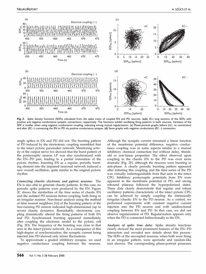
Fig. 3. Spike density functions (SDFs) calculated from the spike trains of coupled EN and PD neurons. (a,b) 25 s long sections of the SDFs withpositive and negative conductance synaptic connections, respectively. The functions exhibit oscillating ®ring patterns in both neurons. Variation of theSDF is smaller when using negative conductance coupling, indicating strong mutual regularization. (c) Phase-portrait graphs before (nC, no connection)and after (EC�) connecting the EN to PD via positive conductance synapse. (d) Same graphs with negative conductance (ECÿ) connection.
450 455 460 465 470 475
450 455 460 465 470 475
Time (s)
(a)
010203040
05
101520
SDF
PD
SDF
EN
Electrical coupling (1)
450 455 460 465 470 475
450 455 460 465 470 475
Time (s)
(b)
0
20
40
0
20
40
60
SDF
PD
SDF
EN
Electrical coupling (2)
0 10 20 30 400
5
10
15
20
0 5 10 15 20 250
5
10
nC EC1
(c)
SDF
PD
[sp
ike/s
]
SDFEN [spike/s] SDFEN [spike/s]
0 10 200
5
10
15
nC
(d)
SDFEN [spike/s]SD
FPD
[sp
ike/s
]0 10 20 30 40 50
0
10
20
30
40
50EC2
SDFEN [spike/s]
NEUROREPORT A. SZUÍ CS ET AL.
566 Vol 11 No 3 28 February 2000
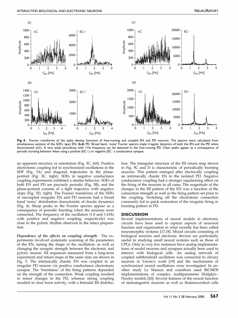
no apparent structure or orientation (Fig. 3C, left). Positiveelectrotonic coupling led to synchronized oscillations in theSDF (Fig. 3A) and diagonal trajectories in the phase-portrait (Fig. 3C, right). SDFs in negative conductancecoupling experiments exhibited a similar behavior. SDFs ofboth EN and PD are precisely periodic (Fig. 3B), and thephase-portrait consists of a tight trajectory with negativeslope (Fig. 3D, right). The Fourier transforms of the SDFsof uncoupled irregular EN and PD neurons had a broadband `noisy' distribution characteristic of chaotic dynamics(Fig. 4). Sharp peaks in the Fourier spectra appear as aconsequence of periodic bursting when the neurons wereconnected. The frequency of the oscillation (1.8 and 1.4Hzwith positive and negative coupling, respectively) wasclose to the pyloric rhythm observed in the intact prepara-tion.
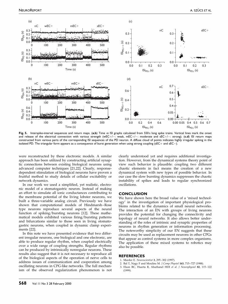
Dependence of the effects on coupling strength: The ex-periments involved systematic scanning of the parametersof the EN, tuning the shape of the oscillation, as well aschanging the synaptic strength between the electronic andpyloric neuron. ISI sequences measured from a long-termexperiment and return maps of the same data are shown inFig. 5. The intrinsically chaotic EN was coupled to anirregular PD neuron via positive conductance electrotonicsynapse. The `burstiness' of the ®ring patterns dependedon the strength of the connection. Weak coupling resultedin minor changes in the PD, whereas strong couplingresulted in clear burst activity, with a bimodal ISI distribu-
tion. The triangular structure of the ISI return map shownin Fig. 5C and D is characteristic of periodically burstingneurons. This pattern emerged after electrically couplingan intrinsically chaotic EN to the isolated PD. Negativeconductance coupling had a stronger regularizing effect onthe ®ring of the neurons in all cases. The magnitude of thechanges in the ISI pattern of the EN was a function of theconnection strength as well as the ®ring pattern set prior tothe coupling. Switching off the electrotonic connectioncommonly led to quick restoration of the irregular ®ring orbursting pattern in PD.
DISCUSSIONSeveral implementations of neural models in electroniccircuits have been used to capture aspects of neuronalfunction and organization in what recently has been calledneuromorphic systems [17,18]. Mixed circuits consisting ofbiological neurons and electronic devices are particularlyuseful in studying small neural systems such as those ofCPGs. Only in very few instances have analog implementa-tions of model neurons and synapses actually been used tointeract with biological cells. An analog network ofcoupled subthreshold oscillators was connected to olivaryneurons in Yarom's work [19] and the mechanisms ofsynchronized neural oscillations were investigated. In an-other study Le Masson and coauthors used BiCMOSimplementations of complex, multiparameter Hodgkin±Huxley models [20]. Several features of the neural functionof stomatogastric neurons as well as thalamocortical cells
Fig. 4. Fourier transforms of the spike density functions of free-running and coupled EN and PD neurons. The spectra were calculated fromsimultaneous sections of the SDFs. (a,c) EN; (b,d) PD. Broad band, `noisy' Fourier spectra imply irregular dynamics of both the EN and the PD whendisconnected (nC). A very weak periodicity with 1Hz frequency can be detected in the free-running PD. Clear peaks appear as a consequence ofperiodic bursting behavior when using a positive (EC�) or negative (ECÿ) conductance synapse.
0 1 2 3 4 0 1 2 3 40
200
400
600
800
1000
(a)
nC EC1
0
2000
4000
6000
Am
plit
ude
fEN [Hz] fEN [Hz]
0 1 2 3 40
200
400
600
800
1000
(c)
nC
Am
plit
ude
fEN [Hz]
0 1 2 3 4
EC2
0
5000
15000
20000
fEN [Hz]
10000
0 1 2 3 4 0 1 2 3 40
200
400
600
800
1400
(b)
nC EC1
0
1000
2000
3000
Am
plit
ude
fPD [Hz] fPD [Hz]
1000
1200
0 1 2 3 40
500
1000
1500
2000
(d)
nC
Am
plit
ude
fPD [Hz]
0 1 2 3 4
EC2
0
5000
15000
20000
fPD [Hz]
10000
INTERACTING BIOLOGICAL AND ELECTRONIC NEURONS NEUROREPORT
Vol 11 No 3 28 February 2000 567
were reconstructed by these electronic models. A similarapproach has been utilized by constructing arti®cial synap-tic connections between existing biological neurons usingadvanced computer techniques [21,22]. Clearly, response-dependent stimulation of biological neurons have proven afruitful method to study details of cellular excitability ornetwork dynamics.
In our work we used a simpli®ed, yet realistic, electro-nic model of a stomatogastric neuron. Instead of makingan effort to simulate all ionic conductances contributing tothe membrane potential of the living lobster neurons, webuilt a three-variable analog circuit. Previously we haveshown that computational models of Hindmarsh±Rosetype neurons reproduce several aspects of the neuralfunction of spiking/bursting neurons [12]. These mathe-matical models exhibited various ®ring/bursting patternsand bifurcations similar to those seen in living stomato-gastric neurons, when coupled in dynamic clamp experi-ments [22].
In this note we have presented evidence that two differ-ent irregular neurons, one biological and one electronic, areable to produce regular rhythm, when coupled electricallyover a wide range of coupling strengths. Regular rhythmscan be produced by intrinsically nonregular neurons. Theseresults also suggest that it is not necessary to reproduce allof the biological aspects of the operation of nerve cells toaddress issues of communication and cooperation amongoscillating neurons in CPG-like networks. The full mechan-ism of the observed regularization phenomenon is not
clearly understood yet and requires additional investiga-tion. However, from the dynamical systems theory point ofview such behavior is plausible: coupling two differentchaotic elements in fact means the creation of a newdynamical system with new types of possible behavior. Inour case the slow bursting dynamics suppresses the chaoticinstability of spikes and leads to regular synchronizedoscillations.
CONCLUSIONWe have shown here the broad value of a `mixed technol-ogy' in the investigation of important physiological pro-blems related to the dynamics of small neural networks.The interaction of an EN with groups of living neuronsprovides the potential for changing the connectivity andtopology of neural networks. It also allows better under-standing of the roles of intrinsic and synaptic properties ofneurons in rhythm generation or information processing.The noteworthy simplicity of our EN suggests that thesecircuits may be used as replacement neurons in other CPGsthat appear as control systems in more complex organisms.The application of these mixed systems to robotics mayalso be possible.
REFERENCES1. Marder E. Neuroscientist 3, 295±302 (1997).
2. Bal T, Nagy F and Moulins M. J Comp Physiol 163, 715±727 (1988).
3. Elson RC, Huerta R, Abarbanel HDI et al. J Neurophysiol 82, 115±122
(1999).
Fig. 5. Interspike-interval sequences and return maps. (a,b) Time vs ISI graphs calculated from 550 s long spike trains. Vertical lines mark the onsetand release of the electrical connection with various strength (wEC�/ÿ: weak, mEC�/ÿ: moderate and sEC�/ÿ: strong). (c,d) ISI return mapsconstructed from various parts of the corresponding ISI sequences of the PD neuron. A diffuse cloud of points indicates highly irregular spiking in theisolated PD. The triangular form appears as a consequence of burst generation when using strong coupling (sEC� and sECÿ).
5000 100 200 300 400
5000 100 200 300 400
Time (s)
0.0
0.1
0.2
0.3
0.0
0.1
0.2
0.3
(a)
nC wEC1 mEC1 sEC1
ISI E
N (
s)IS
I PD
(s)
5000 100 200 300 400
5000 100 200 300 400
Time (s)
0.0
0.1
0.2
0.3
0.0
0.2
0.4
0.6
(b)
nC wEC2 mEC1 sEC2
ISI E
N (
s)IS
I PD
(s)
0.0 0.1 0.2 0.30.0 0.1 0.2 0.30.0
0.1
0.2
0.3
0.0
0.1
0.2
0.3nC sEC1
ISIPD,i (s) ISIPD,i (s)
ISI P
D,i1
1 (
s)
(c)
0.0 0.2 0.4 0.6
ISIPD,i (s)
0.0
0.2
0.4
0.6
ISI P
D,i1
1 (
s)
(d)
nC sEC2
0.00 0.05 0.4 0.5 0.6 0.7
ISIPD,i (s)
0.00
0.05
0.4
0.5
0.6
0.7
NEUROREPORT A. SZUÍ CS ET AL.
568 Vol 11 No 3 28 February 2000

4. Rabinovich MI and Abarbanel HDI. Neuroscience 87, 5±14 (1998).
5. Hayashi H and Ishizuka S. J Theor Biol 156, 269±291 (1992).
6. Mpitsos GJ, Burton RM, Creech HC and Soinila SO. Brain Res Bull 21,
529±538 (1988).
7. Marder E and Calabrese RL. Physiol Rev 76, 687±717 (1996).
8. Harris-Warrick RM, Marder E, Selverston AI and Moulins M. Dynamic
Biological Networks, The Stomatogastric Nervous System. Cambridge MA,
MIT Press, 1992.
9. Mulloney B and Selverston AI. J Comp Physiol 91, 1±32 (1974).
10. Selverston AI and Miller JP. J Neurophysiol 44, 1102±1121 (1980).
11. Hindmarsh JL, and Rose RM. Proc Roy Soc Lond B 221, 87±102 (1984).
12. Rabinovich MI, Abarbanel HDI, Huerta R et al. IEEE Trans Circ Systems
44, 997±1005 (1997).
13. SzuÍcs A. J Neurosci Methods 81, 159±167 (1998).
14. Paulin MG. Biol Cybern 66, 525±531 (1992).
15. Johnson BR, Peck JH, and Harris-Warrick RM. J Comp Physiol 172,
715±732 (1993).
16. Abarbanel HDI. Analysis of Observed Chaotic Data. New York: Springer-
Verlag, 1996.
17. Douglas R, Mahowald M and Mead C. Ann Rev Neurosci 18, 255±281
(1995).
18. Mead C. Analog VLSI and Neural Systems. Reading, MA: Addison-
Wesley, 1989.
19. Yarom Y. Neuroscience 44, 263±275 (1991).
20. Le Masson S, La¯aquieÂre A, Bal T and Le Masson G. IEEE Trans Biomed
Eng 46, 638±645 (1999).
21. Sharp AA, O'Neil MB, Abbott LF and Marder E. Trends Neurosci 16,
389±394 (1993).
22. Elson RC, Selverston AI, Huerta R et al. Phys Rev Lett 81, 5692±5695
(1998).
INTERACTING BIOLOGICAL AND ELECTRONIC NEURONS NEUROREPORT
Vol 11 No 3 28 February 2000 569
The dynamic clamp comes of ageAstrid A. Prinz, L.F. Abbott and Eve Marder
Volen Center and Department of Biology, Brandeis University, Waltham, MA 02454-9110, USA
The dynamic clamp uses computer simulation to intro-
duce artificial membrane or synaptic conductances into
biological neurons and to create hybrid circuits of real
and model neurons. In the ten years since it was first
developed, the dynamic clamp has become a widely
used tool for the study of neural systems at the cellular
and circuit levels. This review describes recent state-of-
the-art implementations of the dynamic clamp and
summarizes insights gained through its use, ranging
from the role of voltage-dependent conductances in
shaping neuronal activity to the effects of synaptic
dynamics on network behavior and the impact of
in vivo-like input on neuronal information processing.
The term dynamic clamp refers to a variety of hardwareand software implementations used to create artificialconductances in neurons. Since its introduction more thanten years ago [1–3], the dynamic clamp has become astandard tool of electrophysiology, used in awide variety ofexperimental preparations to address a host of differentissues. This review describes how the dynamic clampcreates an artificial conductance, provides an overview ofsome of the different dynamic-clamp systems currently inuse and discusses what can and has been achieved usingthe technique.
What is the dynamic clamp?
In contrast to conventional voltage- or current-clamprecording configurations, the dynamic clamp effectivelyalters the conductance of a neuron [1,2]. It does so by usingthe measured membrane potential to control the amountof current injected into a neuron. To simulate a particularconductance, the dynamic clamp computes the differencebetween the measured membrane potential and thereversal potential for that conductance, multiplies this‘driving force’ by the desired amount of conductance, andinjects the resulting current into the neuron. Accuratedynamic-clamp performance requires uninterrupted,rapid sampling of the membrane potential and fastcomputation of the current to be injected. If the samplingand computation are fast enough, the electrophysiologicaleffects of any set of ion-conducting channels can be repro-duced as if these were located at the site of voltagemeasurement and current injection.
Any time- or voltage-dependent conductance that hasbeen described mathematically and can be simulated on acomputer can be introduced into a neuron using thedynamic clamp. For a voltage-dependent conductance, theinjected current is determined by a set of differential
equations that describe the voltage and time dependenceof the conductance. For a synaptic conductance, thecurrent injected by the dynamic clamp is computed onthe basis of presynaptic input that is either recorded fromanother neuron, or generated by a model neuron or by adescriptive model of typical in vivo input.
Dynamic-clamp implementations
Obtaining sufficiently high update rates in the firstdynamic-clamp implementations of the early 1990spushed the limits of computer and data acquisitionboard technologies available at that time. As a result,some of the earliest dynamic-clamp programs werewritten in machine language [1,2] and used look-uptables [3], and some implementations used digitalsignal processing (DSP) boards to achieve the requiredspeed [4]. Today, computers and boards are so fast thathardware speed is no longer a significant issue, andmany different dynamic-clamp systems have beendeveloped and used in several laboratories aroundthe world. These systems vary considerably in theirfront-end user interfaces, in how readily programmablethey are, in how many different conductances can besimulated, in how many neurons can be studiedsimultaneously, in whether they display and savevoltage and current traces online, and in their cost.Our conservative estimate is that there are at least 20different dynamic-clamp setups in use in laboratoriesaround the world today, and many more papers thancan be cited here have been published with someversion of dynamic-clamp implementation. Table 1 listsseveral of the dynamic-clamp systems presently in useto illustrate the diversity of approaches, hardware, andfeatures. Because computers and boards change soquickly, this list provides only a snapshot of thepresent situation.
Currently available implementations of the dynamicclamp include applications that run under the Windows orReal-Time Linux operating systems, systems that useembedded processors or DSP boards, and versions that useanalog devices. The advantages and disadvantages ofthese different approaches are outlined briefly below.
Windows-based applications
Windows-based dynamic-clamp systems typicallyachieve update rates of 2–20 kHz, depending on thecomputational load for the particular conductancesbeing simulated [5–7]. This is fast enough for mostpurposes, but extremely fast conductances, such asthose of fast Naþ currents, can only be approximatedcrudely. An additional problem stems from the fact thatCorresponding author: Astrid A. Prinz ([email protected]).
Review TRENDS in Neurosciences Vol.27 No.4 April 2004
www.sciencedirect.com 0166-2236/$ - see front matter q 2004 Elsevier Ltd. All rights reserved. doi:10.1016/j.tins.2004.02.004
any Windows-based program must deal with operatingsystem interrupts through which Windows distributesprocessor time between different tasks. These can leadto discontinuities and gaps in dynamic-clamp operationand prevent real-time performance, even at low updaterates.
The Windows-based dynamic clamp described by Pintoand colleagues [6] uses a Digidata 1200 board (AxonInstruments, http://www.axon.com) for data acquisitionand digital-to-analog conversion. Because such boards arecommonly used (and this dynamic-clamp software isavailable for free download from the developers), thisparticular implementation requires no more of a financialinvestment than that required for a standard electro-physiology rig.
Real-Time Linux-based applications
Recently developed versions of the dynamic clamp thatoperate under Real-Time Linux avoid the interruptproblem of a Windows-based system and can achieveupdate rates of 20–50 kHz, depending on the dataacquisition board [8–10]. At the moment, the installationand operation of the real-time operating system requiresconsiderable expertise, which can deter some users. How-ever, with several laboratories developing more user-friendly Real-Time Linux-based dynamic-clamp systems,the installation and use of these systems is rapidlybecoming easier.
Embedded-processor and DSP-based systems
Update rates of 20–50 kHz can also be achieved by usingan embedded processor or DSP board [4,11–13]. Thesedevices can be controlled by a host computer andprogrammed through a graphical programming languagewith a user-friendly interface [12] or through Real-TimeWorkshop (The MathWorks, http://www.mathworks.com),but these advantages literally come at a high price. Thecosts for the additional hardware, necessary drivers, andcompiler software can be betweenUS$5000 andUS$10 000.
Analog devices
For some applications, the dynamic clamp can be imple-mented using analog circuits that perform the basic
subtraction and multiplication operations needed toconvert a desired conductance and a measured potentialinto an injected current [14]. These analog circuits arecommercially available (e.g. SM-1 from CambridgeConductance, http://homepage.ntlworld.com/cambridge.conductance; or ITC-18 from Instrutech Corporation,http://www.instrutech.com). The advantage of an analogapproach is its high speed, which is essentially instan-taneous on the scale of typical membrane and synaptictime constants. However, the basic analog system onlymakes the conversion from conductance to injectedcurrent. For any application other than the simulation ofa constant conductance, these systemsmust be driven by adigital computer programmed to calculate the desiredconductance and drive the analog circuitry. As a result,analog systems are most useful in cases where synaptic,rather than voltage-dependent, conductances are beingsimulated.
Applications of the dynamic clamp
Uses of the dynamic clamp have been divided here into fivebroad categories: simulation of voltage-independent con-ductances, simulation of voltage-dependent conductances,simulation of synapses between neurons, construction ofbiological–computer hybrid circuits, and simulation ofin vivo synaptic input. For each of these categories, a singleexample from the many possibilities in the literature hasbeen chosen to illustrate what can be achieved and whathas been learned using these approaches. Additionalselected studies using the same dynamic-clamp approachare briefly summarized for each category.
Effects of voltage-independent conductances
Simulating a voltage-independent conductance is thesimplest thing that can be achieved with the dynamicclamp (Figure 1a) but, nevertheless, it is useful forstudying the effects of leakage conductances or ligand-gated conductances on neuronal dynamics. Figure 1bprovides an example inwhich a dynamic clampwas used toduplicate the effect of a ligand-gated conductance with areversal potential of275 mV in a neuron of the crustaceanstomatogastric ganglion to study the effects of a voltage-independent GABA conductance [2].
Table 1. Recent examples of dynamic-clamp implementationsa
Windows-based Real-time Linux-based Embedded processor orDSP
Analog device
References [6] [9] [10] [12] [14] Instrutech, ITC-18URL inls.ucsd.edu/~rpinto/ www.bu.edu/ndl/rtldc.
htmlwww.neuro.gatech.edu/mrci/
NA NA www.instrutech.com
Programming language Cþþ C, Cþþfor user interface MRCI modelinglanguage, C
Real-Time LabView NA NA
Update rateb 10 kHz 20 kHzd 30 kHz 40 kHz NA 50 kHzExisting applications Artificial conductances;
artificial chemical orelectrical synapsesbetween up to four cells
Artificial conductances;hybrid two-cell networks;adding multiplecompartments
Artificial synapticinputs; hybrid two-cell networks
Artificial conductances;artificial chemicalsynapses; recordingcurrent–voltage curves
Artificial synaptic inputs Artificial synapticinputs
Number of channelsc Four in, four out Two in, two outd Two in, two out Two in, one out Four in, four out Four in, four outUser interface Graphical Graphical Command line Graphical NA NASaves traces? No Yes Yes Yes NA NADisplays traces? No Yes No Yes NA NA
aAbbreviations: DSP, digital signal processing; MRCI, model reference current injection; NA, not available.bUpdate rates vary depending on the computational load. Updates rates given here are maximum values of published versions of the systems and will increase with time.cChannel numbers given here are those of published versions of the systems. Most systems can be modified to handle larger channel numbers if different hardware is used.dNewer, unpublished versions of this system can achieve update rates of up to 40 kHz, and can handle as many as 16 input and 2 output channels (J. White, pers. commun.).
Review TRENDS in Neurosciences Vol.27 No.4 April 2004 219
www.sciencedirect.com
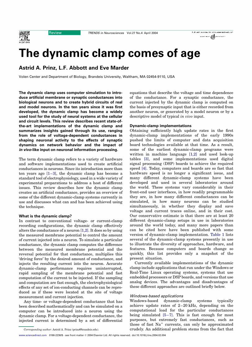
Dynamic-clamp conductances act in parallel with thenormal membrane conductances of the neuron, and theinteraction between the added and existing conductancesis what makes such manipulations interesting. In theexample shown in Figure 1b, current pulses of constantamplitude were introduced to show that the dynamicclamp was modifying the conductance of the neuron(Figure 1b, bottom) in exactly the same way as a bathapplication of GABA (Figure 1b, top). The dynamic clampmimics both the GABA-induced hyperpolarization and thereduction in the voltage response to constant-amplitudecurrent pulses caused by the GABA conductance. In arelated approach, the dynamic clamp has been used to addartificial GABA conductances in thalamocortical relaycells to elucidate the role of GABA-mediated inhibitorypostsynaptic potentials (IPSPs) in rebound burst firingand burst inhibition [15,16].
In addition to being added, conductances can, with somerestrictions, be subtracted using the dynamic clamp.Figure 1c shows an example. The leakage conductanceintroduced by the electrode penetration required forintracellular recordings made with sharp electrodes is apotential source of distortion of the natural activity of therecorded neuron. Figure 1c shows an example in which thedynamic clamp was used to simulate a negative conduc-tance designed to cancel out the impact of the leakageintroduced by electrode penetration [17]. Addition of anartificial leak conductance had been shown previously toswitch leech heartbeat interneurons from an active statewith high-frequency bursting to an inactive state [18].Because of this sensitivity of bursting to additional leakconductance, the electrode leak was removed by thedynamic clamp. The bursting activity that is the naturalmode of operation for this neuron was revealed only afterthe leakage conductance introduced by electrode pene-tration was subtracted using the dynamic clamp.
Taken together, dynamic-clamp studies that simulatevoltage-independent conductances in different prepar-ations demonstrate important roles for seemingly simpleleak and ligand-gated currents in shaping neural activity.The importance of voltage-independent conductances isfurther supported by reports that dynamic-clamp simu-lated leak current can increase motoneuron spiking in themammalian spinal cord [19] and that adding a Ca2þ
window current or subtracting leak current can renderthalamocortical neurons bistable [20].
Figure 1. Using the dynamic clamp to simulate voltage-independent conductances.
(a) Schematic of the experimental configuration. The dynamic clamp computes
the current, I, flowing through a voltage-independent conductance, g, as g multi-
plied by the instantaneous driving force, V–E, where E is the reversal potential and
V is the membrane potential. In every cycle of dynamic-clamp operation, V is
measured and fed into the computer, I is computed based on the momentary
value of V, and I is injected into the cell. Voltage measurement and current injec-
tion can be made through the same electrode with discontinuous clamp tech-
niques, or through two separate electrodes. (b) Voltage traces recorded from a
cultured crab stomatogastric neuron during 30 s bath application of 0.1 mM GABA
(top) and during dynamic-clamp injection of an exponentially rising (t ¼ 5 s) and
falling (t ¼ 15 s) GABA conductance with a reversal potential of 275 mV (bottom).
The starts of bath and dynamic-clamp application are indicated by asterisks.
During both runs, current pulses of 20.5 nA were applied every 3 s to illustrate the
change in input conductance. Adapted, with permission, from Ref. [2]. (c) Voltage
trace from a leech heart interneuron before and during injection of a negative leak
conductance of 26 nS with a reversal potential at 0 mV. The leak subtraction com-
pensates for the effect of sharp microelectrode penetration, which suppresses
bursting. Adapted, with permission, from Ref. [17] q (2002) by the Society for
Neuroscience.
I = g*(V–E)
V
I
GABA
Dynamic clamp
*V
V
*
–46 mV
–46 mV
(a)
(b)
(c)
10 mV4 s
Simulatingvoltage-independent
conductances
–50 mV
V
10 mV2 s
Dynamic clamp leak subtraction
V
TRENDS in Neurosciences
Figure 2. Adding or subtracting voltage-dependent conductances. (a) Schematic of
the experimental configuration. The dynamic-clamp current is computed as in
Figure 1, but in this case the conductance, g, varies with time and depends on the
membrane potential, V. (b) Each panel shows 65 superimposed spikes from an
Aplysia R20 neuron in response to 7 Hz current pulse injection. In control con-
ditions, the action potential is initially narrow and broadens during the spike train
(top-left). Spike broadening is abolished in 50 mM tetraethylammonium (TEA) and
10 mM 4-aminopyridine (4-AP; top-middle) and rescued when an A-type and a
delayed-rectifier Kþ current are added with the dynamic clamp (top-right). In a
different cell (bottom), the action of the blockers was approximated by subtracting
these two conductances with the dynamic clamp. Adapted, with permission, from
Ref. [21]q (1996) by the Society for Neuroscience.
TRENDS in Neurosciences
I
VI = g(V)*(V–E)
V
Cell 1
Cell 2
(a)
(b)
Adding or subtractingvoltage-gatedconductances
Dynamic-clampsubtraction
Control
Control
Pharmacologicalblock
Dynamic-clamprescue
40 mV
20 ms
Review TRENDS in Neurosciences Vol.27 No.4 April 2004220
www.sciencedirect.com
Effects of voltage-dependent conductances
The dynamic clamp can be used to introduce voltage-dependent conductances into a neuron (Figure 2a),which is useful for exploring the impact of differentintrinsic membrane conductances on neuronal activity.Specific conductances already present in the ensembleof intrinsic conductances in the neuron can beaugmented or decremented to reveal the role thatthey play in generating its particular pattern of firing.Used in this manner, the dynamic clamp supplementsmore traditional methods of blocking conductancespharmacologically because it allows for very specifictargeting and very precise control of the amount of themodification being made on any conductance. Inaddition, non-native voltage-dependent conductancescan be added to the natural complement of the neuronto see what novel dynamics can be generated.
Figure 2b provides an example of this type of manipu-lation [21]. Each panel shows 65 superimposed spikesrecorded from an Aplysia R20 neuron responding to theinjection of current pulses at 7 Hz. In control conditions,the action potential broadens during repetitive spiking(Figure 2b, top-left). This broadening was abolished whenA-typeanddelayed-rectifierKþ conductanceswerepharma-cologically blocked because the initial spikes were alreadybroad (Figure 2b, top-middle). Spike broadening wasrestored under the pharmacological block by addingthese conductances back using the dynamic clamp(Figure 2b, top-right). This result clearly implicatesA-type and delayed-rectifier Kþ conductances in thephenomenon of spike broadening. The dynamic clampcould also partially duplicate the effect of the pharmaco-logical blockade when it was used to subtract these twoconductances (Figure 2b, bottom).
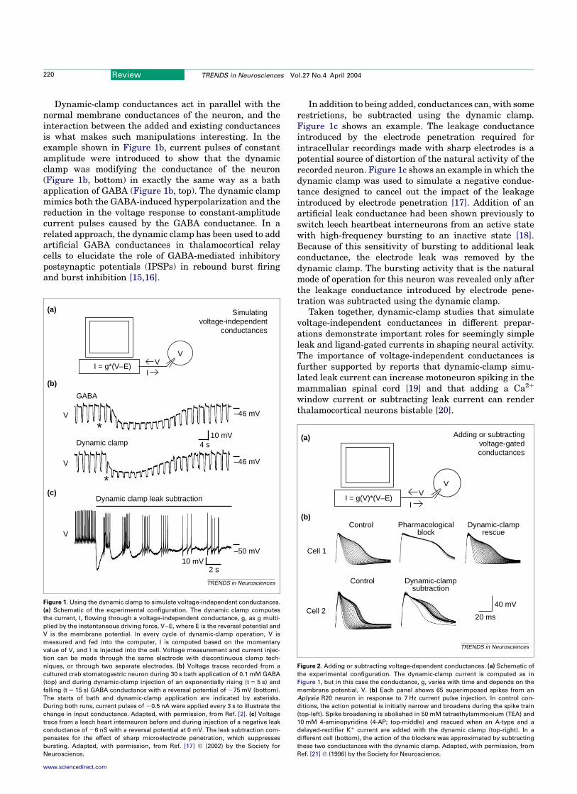
Dynamic-clamp simulation of voltage-dependent con-ductances has been used in stomatogastric ganglionneurons to investigate the roles of transient Kþ
currents and hyperpolarization-activated inward cur-rents [22,23], to study the effects of a neuromodulatorypeptide-elicited current on the output of a rhythmicnetwork [24], to show that a slow Kþ conductance canunderlie cellular short-term memory [25], and todemonstrate how the relative amounts of different
Ca2þ and Kþ conductances can determine whether aneuron is silent, spikes tonically, or bursts [26].Artificial voltage-dependent currents have been usedin preparations as diverse as pancreatic b-cells[27,28], thalamocortical [29] and neocortical neurons [5],and hippocampal interneurons [11]. The dynamic-clampstudies in these systems have identified individualvoltage-dependent conductances involved in subthres-hold membrane resonances [5], high-frequency spiking[11], bursting [27–29] and delta oscillations [29], andhave thus contributed considerably to our under-standing of dynamic processes in these systems.
Building and modifying neuronal circuits with artificial
synapses
Thus far, we have focused on applications in which thedynamic clamp is used to introduce or removemembrane conductances to assess their role at thesingle neuron level. The remaining examples show usesof the dynamic clamp for creating artificial synapticconductances. In these applications, the neuron beingdynamically clamped acts as the postsynaptic element,and another neuron or a computer model acts as thesource of presynaptic input. Here, cases in which thepresynaptic element is another neuron are considered.As illustrated in Figure 3a, this approach requiresrecording the membrane potential of the ‘presynaptic’neuron and using it and the dynamic clamp to controlcurrent injection into the ‘postsynaptic’ neuron. Asynapse in an existing circuit can be augmented ordecremented to study its effect on network activity, or asimulated synapse can be introduced where noneexisted before, allowing for the construction andstudy of completely novel neural circuits. The dynamicclamp provides the experimenter with complete controlover the strength and other properties of theseartificial synapses.
Figure 3b shows an example in which a so-called ‘half-center’ oscillator was constructed by connecting twostomatogastric ganglion neurons with reciprocally inhibi-tory synapses thatwere simulatedwith the dynamic clamp[6]. To construct the half-center oscillator, the two neuronswere first isolated and then connected by artificial
Figure 3. Creating artificial synapses between real neurons. (a) Schematic of the experimental configuration. The current that is injected into the postsynaptic neuron (IPD or
ILP) is the product of the synaptic conductance, which depends on the membrane potential of the presynaptic neuron, and the driving force. (b) Voltage and dynamic-clamp
current traces for a pyloric dilator (PD) and a lateral pyloric (LP) neuron of the lobster stomatogastric ganglion before and after the dynamic clamp was switched on. The
artificial synapses induced the neurons to oscillate in antiphase. Adapted, with permission, from Ref. [6].
TRENDS in Neurosciences
IPD
ILP
VPD
VLP
Dynamic clamp off Dynamic clamp on
20 m
V10
nA
(a) Simulating synapses
VPD
IPD = g(VLP)*(VPD–E)
ILP = g(VPD)*(VLP–E)ILP
VLP
(b)
VLP
IPD
VPD
Review TRENDS in Neurosciences Vol.27 No.4 April 2004 221
www.sciencedirect.com
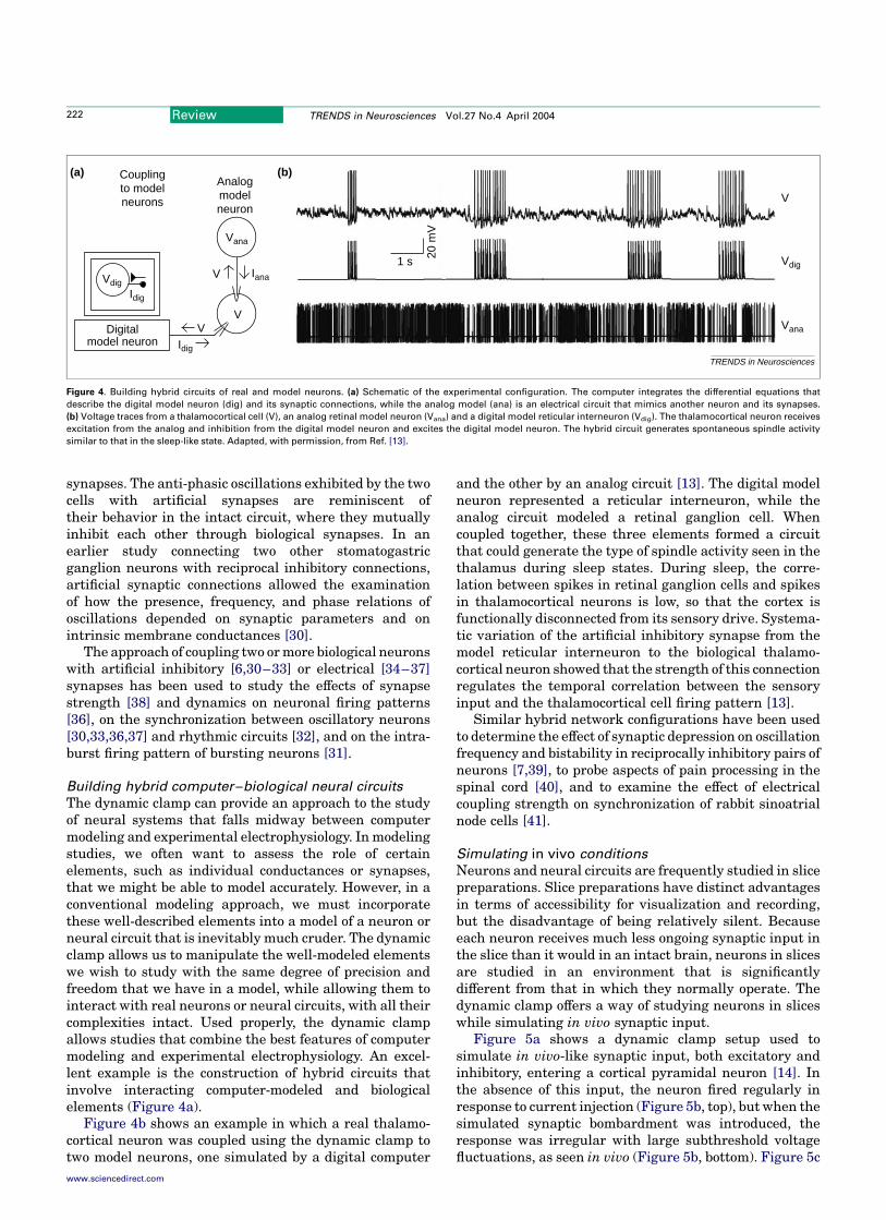
synapses. The anti-phasic oscillations exhibited by the twocells with artificial synapses are reminiscent oftheir behavior in the intact circuit, where they mutuallyinhibit each other through biological synapses. In anearlier study connecting two other stomatogastricganglion neurons with reciprocal inhibitory connections,artificial synaptic connections allowed the examinationof how the presence, frequency, and phase relations ofoscillations depended on synaptic parameters and onintrinsic membrane conductances [30].
The approach of coupling two ormore biological neuronswith artificial inhibitory [6,30–33] or electrical [34–37]synapses has been used to study the effects of synapsestrength [38] and dynamics on neuronal firing patterns[36], on the synchronization between oscillatory neurons[30,33,36,37] and rhythmic circuits [32], and on the intra-burst firing pattern of bursting neurons [31].
Building hybrid computer–biological neural circuits
The dynamic clamp can provide an approach to the studyof neural systems that falls midway between computermodeling and experimental electrophysiology. Inmodelingstudies, we often want to assess the role of certainelements, such as individual conductances or synapses,that we might be able to model accurately. However, in aconventional modeling approach, we must incorporatethese well-described elements into a model of a neuron orneural circuit that is inevitably much cruder. The dynamicclamp allows us to manipulate the well-modeled elementswe wish to study with the same degree of precision andfreedom that we have in a model, while allowing them tointeract with real neurons or neural circuits, with all theircomplexities intact. Used properly, the dynamic clampallows studies that combine the best features of computermodeling and experimental electrophysiology. An excel-lent example is the construction of hybrid circuits thatinvolve interacting computer-modeled and biologicalelements (Figure 4a).
Figure 4b shows an example in which a real thalamo-cortical neuron was coupled using the dynamic clamp totwo model neurons, one simulated by a digital computer
and the other by an analog circuit [13]. The digital modelneuron represented a reticular interneuron, while theanalog circuit modeled a retinal ganglion cell. Whencoupled together, these three elements formed a circuitthat could generate the type of spindle activity seen in thethalamus during sleep states. During sleep, the corre-lation between spikes in retinal ganglion cells and spikesin thalamocortical neurons is low, so that the cortex isfunctionally disconnected from its sensory drive. Systema-tic variation of the artificial inhibitory synapse from themodel reticular interneuron to the biological thalamo-cortical neuron showed that the strength of this connectionregulates the temporal correlation between the sensoryinput and the thalamocortical cell firing pattern [13].
Similar hybrid network configurations have been usedto determine the effect of synaptic depression on oscillationfrequency and bistability in reciprocally inhibitory pairs ofneurons [7,39], to probe aspects of pain processing in thespinal cord [40], and to examine the effect of electricalcoupling strength on synchronization of rabbit sinoatrialnode cells [41].
Simulating in vivo conditions
Neurons and neural circuits are frequently studied in slicepreparations. Slice preparations have distinct advantagesin terms of accessibility for visualization and recording,but the disadvantage of being relatively silent. Becauseeach neuron receives much less ongoing synaptic input inthe slice than it would in an intact brain, neurons in slicesare studied in an environment that is significantlydifferent from that in which they normally operate. Thedynamic clamp offers a way of studying neurons in sliceswhile simulating in vivo synaptic input.
Figure 5a shows a dynamic clamp setup used tosimulate in vivo-like synaptic input, both excitatory andinhibitory, entering a cortical pyramidal neuron [14]. Inthe absence of this input, the neuron fired regularly inresponse to current injection (Figure 5b, top), but when thesimulated synaptic bombardment was introduced, theresponse was irregular with large subthreshold voltagefluctuations, as seen in vivo (Figure 5b, bottom). Figure 5c
Figure 4. Building hybrid circuits of real and model neurons. (a) Schematic of the experimental configuration. The computer integrates the differential equations that
describe the digital model neuron (dig) and its synaptic connections, while the analog model (ana) is an electrical circuit that mimics another neuron and its synapses.
(b) Voltage traces from a thalamocortical cell (V), an analog retinal model neuron (Vana) and a digital model reticular interneuron (Vdig). The thalamocortical neuron receives
excitation from the analog and inhibition from the digital model neuron and excites the digital model neuron. The hybrid circuit generates spontaneous spindle activity
similar to that in the sleep-like state. Adapted, with permission, from Ref. [13].
TRENDS in Neurosciences
1 s 20 m
V
V
Vdig
VanaDigitalmodel neuron
Vdig
V
Vana
Idig
Analogmodelneuron
(b)(a) Couplingto modelneurons
Idig
V
V Iana
Review TRENDS in Neurosciences Vol.27 No.4 April 2004222
www.sciencedirect.com
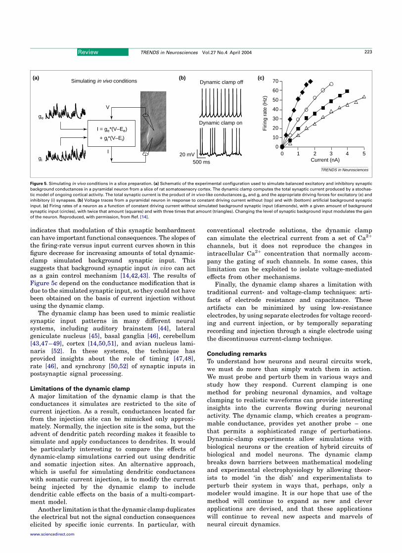
indicates that modulation of this synaptic bombardmentcan have important functional consequences. The slopes ofthe firing-rate versus input current curves shown in thisfigure decrease for increasing amounts of total dynamic-clamp simulated background synaptic input. Thissuggests that background synaptic input in vivo can actas a gain control mechanism [14,42,43]. The results ofFigure 5c depend on the conductance modification that isdue to the simulated synaptic input, so they could not havebeen obtained on the basis of current injection withoutusing the dynamic clamp.
The dynamic clamp has been used to mimic realisticsynaptic input patterns in many different neuralsystems, including auditory brainstem [44], lateralgeniculate nucleus [45], basal ganglia [46], cerebellum[43,47–49], cortex [14,50,51], and avian nucleus lami-naris [52]. In these systems, the technique hasprovided insights about the role of timing [47,48],rate [46], and synchrony [50,52] of synaptic inputs inpostsynaptic signal processing.
Limitations of the dynamic clamp
A major limitation of the dynamic clamp is that theconductances it simulates are restricted to the site ofcurrent injection. As a result, conductances located farfrom the injection site can be mimicked only approxi-mately. Normally, the injection site is the soma, but theadvent of dendritic patch recording makes it feasible tosimulate and apply conductances to dendrites. It wouldbe particularly interesting to compare the effects ofdynamic-clamp simulations carried out using dendriticand somatic injection sites. An alternative approach,which is useful for simulating dendritic conductanceswith somatic current injection, is to modify the currentbeing injected by the dynamic clamp to includedendritic cable effects on the basis of a multi-compart-ment model.
Another limitation is that the dynamic clamp duplicatesthe electrical but not the signal conduction consequenceselicited by specific ionic currents. In particular, with
conventional electrode solutions, the dynamic clampcan simulate the electrical current from a set of Ca2þ
channels, but it does not reproduce the changes inintracellular Ca2þ concentration that normally accom-pany the gating of such channels. In some cases, thislimitation can be exploited to isolate voltage-mediatedeffects from other mechanisms.
Finally, the dynamic clamp shares a limitation withtraditional current- and voltage-clamp techniques: arti-facts of electrode resistance and capacitance. Theseartifacts can be minimized by using low-resistanceelectrodes, by using separate electrodes for voltage record-ing and current injection, or by temporally separatingrecording and injection through a single electrode usingthe discontinuous current-clamp technique.
Concluding remarks
To understand how neurons and neural circuits work,we must do more than simply watch them in action.We must probe and perturb them in various ways andstudy how they respond. Current clamping is onemethod for probing neuronal dynamics, and voltageclamping to realistic waveforms can provide interestinginsights into the currents flowing during neuronalactivity. The dynamic clamp, which creates a program-mable conductance, provides yet another probe – onethat permits a sophisticated range of perturbations.Dynamic-clamp experiments allow simulations withbiological neurons or the creation of hybrid circuits ofbiological and model neurons. The dynamic clampbreaks down barriers between mathematical modelingand experimental electrophysiology by allowing theor-ists to model ‘in the dish’ and experimentalists toperturb their system in ways that, perhaps, only amodeler would imagine. It is our hope that use of themethod will continue to expand as new and cleverapplications are devised, and that these applicationswill continue to reveal new aspects and marvels ofneural circuit dynamics.
Figure 5. Simulating in vivo conditions in a slice preparation. (a) Schematic of the experimental configuration used to simulate balanced excitatory and inhibitory synaptic
background conductances in a pyramidal neuron from a slice of rat somatosensory cortex. The dynamic clamp computes the total synaptic current produced by a stochas-
tic model of ongoing cortical activity. The total synaptic current is the product of in vivo-like conductances ge and gi and the appropriate driving forces for excitatory (e) and
inhibitory (i) synapses. (b) Voltage traces from a pyramidal neuron in response to constant driving current without (top) and with (bottom) artificial background synaptic
input. (c) Firing rates of a neuron as a function of constant driving current without simulated background synaptic input (diamonds), with a given amount of background
synaptic input (circles), with twice that amount (squares) and with three times that amount (triangles). Changing the level of synaptic background input modulates the gain
of the neuron. Reproduced, with permission, from Ref. [14].
TRENDS in Neurosciences
500 ms20 mV
Simulating in vivo conditions(a) (b) (c)
ge
gi
I = ge*(V–Ee)
+ gi*(V–Ei)
V
I
Dynamic clamp off
Dynamic clamp on
Current (nA)
Firi
ng r
ate
(Hz)
70
60
50
40
30
20
10
00 1 2 3 4 5
Review TRENDS in Neurosciences Vol.27 No.4 April 2004 223
www.sciencedirect.com

AcknowledgementsOur research is supported by MH46742 and the Sloan/Swartz Center for
Theoretical Neurobiology at Brandeis University.
References1 Sharp, A.A. et al. (1993) The dynamic clamp: artificial conductances in
biological neurons. Trends Neurosci. 16, 389–394
2 Sharp, A.A. et al. (1993) Dynamic clamp: computer-generated
conductances in real neurons. J. Neurophysiol. 69, 992–995
3 Robinson, H.P. and Kawai, N. (1993) Injection of digitally synthesized
synaptic conductance transients to measure the integrative properties
of neurons. J. Neurosci. Methods 49, 157–165
4 LeMasson, G. et al. (1995) From conductances to neural network
properties: analysis of simple circuits using the hybrid network
method. Prog. Biophys. Mol. Biol. 64, 201–220
5 Hutcheon, B. et al. (1996)Models of subthresholdmembrane resonance
in neocortical neurons. J. Neurophysiol. 76, 698–714
6 Pinto, R.D. et al. (2001) Extended dynamic clamp: controlling up to four
neurons using a single desktop computer and interface. J. Neurosci.
Methods 108, 39–48
7 Manor, Y. and Nadim, F. (2001) Synaptic depression mediates
bistability in neuronal networks with recurrent inhibitory connec-
tivity. J. Neurosci. 21, 9460–9470
8 Butera, R.J. et al. (2001) Amethodology for achieving high-speed rates
for artificial conductance injection in electrically excitable biological
cells. IEEE Trans. Biomed. Eng. 48, 1460–1470
9 Dorval, A.D. et al. (2001) Real-time linux dynamic clamp: a fast and
flexible way to construct virtual ion channels in living cells. Ann.
Biomed. Eng. 29, 897–907
10 Raikov, I. et al. MRCI: a flexible real-time dynamic clamp system for
electrophysiology experiments. J. Neurosci. Methods (in press)
11 Lien, C.C. and Jonas, P. (2003) Kv3 potassium conductance is
necessary and kinetically optimized for high-frequency action poten-
tial generation in hippocampal interneurons. J. Neurosci. 23,
2058–2068
12 Kullmann, P.H.M. et al. (2004) Implementation of a fast 16-bit dynamic
clamp using LabView-RT. J. Neurophysiol. 91, 542–554
13 Le Masson, G. et al. (2002) Feedback inhibition controls spike transfer
in hybrid thalamic circuits. Nature 417, 854–858
14 Chance, F.S. et al. (2002) Gain modulation from background synaptic
input. Neuron 35, 773–782
15 Ulrich, D. and Huguenard, J.R. (1996) g-Aminobutyric acid type B
receptor-dependent burst-firing in thalamic neurons: a dynamic clamp
study. Proc. Natl. Acad. Sci. U. S. A. 93, 13245–13249
16 Ulrich, D. and Huguenard, J.R. (1997) GABAA-receptor-mediated
rebound burst firing and burst shunting in thalamus. J. Neurophysiol.
78, 1748–1751
17 Cymbalyuk, G.S. et al. (2002) Bursting in leech heart interneurons:
cell-autonomous and network-based mechanisms. J. Neurosci. 22,
10580–10592
18 Gramoll, S. et al. (1994) Switching in the activity of an interneuron
that controls coordination of the hearts in the medicinal leech (Hirudo
medicinalis). J. Exp. Biol. 186, 157–171
19 Kiehn, O. et al. (2000) Contributions of intrinsic motor neuron
properties to the production of rhythmic motor output in the
mammalian spinal cord. Brain Res. Bull. 53, 649–659
20 Hughes, S.W. et al. (1999) All thalamocortical neurones possess a
T-type Ca2þ ‘window’ current that enables the expression of bistability-
mediated activities. J. Physiol. 517, 805–815
21 Ma, M. and Koester, J. (1996) The role of potassium currents in
frequency-dependent spike broadening in Aplysia R20 neurons: a
dynamic clamp analysis. J. Neurosci. 16, 4089–4101
22 Harris-Warrick, R.M. et al. (1995) Dopamine modulation of two
subthreshold currents produces phase shifts in activity of an identified
motoneuron. J. Neurophysiol. 74, 1404–1420
23 Zhang, Y. et al. (2003) Overexpression of a hyperpolarization-activated
cation current (Ih) channel gene modifies the firing activity of
identified motor neurons in a small neural network. J. Neurosci. 23,
9059–9067
24 Swensen, A.M. and Marder, E. (2001) Modulators with convergent
cellular actions elicit distinct circuit outputs. J. Neurosci. 21,
4050–4058
25 Turrigiano, G.G. et al. (1996) Cellular short-term memory from a slowpotassium conductance. J. Neurophysiol. 75, 963–966
26 Goldman, M.S. et al. (2001) Global structure, robustness, andmodulation of neuronal models. J. Neurosci. 21, 5229–5238
27 Bertram, R. et al. (2000) The phantom burster model for pancreaticb-cells. Biophys. J. 79, 2880–2892
28 Kinard, T.A. et al. (1999) Modulation of the bursting properties ofsingle mouse pancreatic b-cells by artificial conductances. Biophys. J.76, 1423–1435
29 Hughes, S.W. et al. (1998) Dynamic clamp study of Ih modulation ofburst firing and delta oscillations in thalamocortical neurons in vitro.Neuroscience 87, 541–550
30 Sharp, A.A. et al. (1996) Mechanisms of oscillation in dynamic clampconstructed two-cell half-center circuits. J. Neurophysiol. 76, 867–883
31 Szucs, A. et al. (2003) Synaptic modulation of the interspike intervalsignatures of bursting pyloric neurons. J. Neurophysiol. 89,1363–1377
32 Bartos, M. et al. (1999) Coordination of fast and slow rhythmicneuronal circuits. J. Neurosci. 19, 6650–6660
33 Elson, R.C. et al. (2002) Inhibitory synchronization of burstingin biological neurons: dependence on synaptic time constant.J. Neurophysiol. 88, 1166–1176
34 Joyner, R.W. et al. (1991) Unidirectional block between isolated rabbitventricular cells coupled by a variable resistance. Biophys. J. 60,1038–1045
35 Sharp, A.A. et al. (1992) Artificial electrical synapses in oscillatorynetworks. J. Neurophysiol. 67, 1691–1694
36 Velazquez, J.L.P. et al. (2001) Artificial electrotonic coupling affectsneuronal firing patterns depending upon cellular characteristics.Neuroscience 103, 841–849
37 Elson, R.C. et al. (1998) Synchronous behavior of two coupled biologicalneurons. Phys. Rev. Lett. 81, 5692–5695
38 Prinz, A.A. et al. (2003) The functional consequences of changes in thestrength and duration of synaptic inputs to oscillatory neurons.J. Neurosci. 23, 943–954
39 Manor, Y. andNadim, F. (2001) Frequency regulation demonstrated bycoupling a model and a biological neuron. Neurocomputing 38,269–278
40 Derjean, D. et al. (2003) Dynamic balance of metabotropic inputscauses dorsal horn neurons to switch functional states. Nat. Neurosci.
6, 274–28141 Wilders, R. et al. (1996) Model clamp and its application to
synchronization of rabbit sinoatrial node cells. Am. J. Physiol. 271,H2168–H2182
42 Doiron, B. et al. (2001) Subtractive and divisive inhibition: effect ofvoltage-dependent inhibitory conductances and noise.Neural Comput.
13, 227–24843 Mitchell, S.J. and Silver, R.A. (2003) Shunting inhibition modulates
neuronal gain during synaptic excitation. Neuron 38, 433–44544 Svirskis, G. et al. (2002) Enhancement of signal-to-noise ratio and
phase locking for small inputs by a low-threshold outward current inauditory neurons. J. Neurosci. 22, 11019–11025
45 Blitz, D.M. and Regehr, W.G. (2003) Retinogeniculate synapticproperties controlling spike number and timing in relay neurons.J. Neurophysiol. 90, 2438–2450
46 Hanson, J.E. and Jaeger, D. (2002) Short-term plasticity shapes theresponse to simulated normal and parkinsonian input patterns in theglobus pallidus. J. Neurosci. 22, 5164–5172
47 Carter, A.G. and Regehr, W.G. (2002) Quantal events shape cerebellarinterneuron firing. Nat. Neurosci. 5, 1309–1318
48 Gauck, V. and Jaeger, D. (2000) The control of rate and timing of spikesin the deep cerebellar nuclei by inhibition. J. Neurosci. 20, 3006–3016
49 Jaeger, D. and Bower, J.M. (1999) Synaptic control of spiking incerebellar Purkinje cells: dynamic current clamp based on modelconductances. J. Neurosci. 19, 6090–6101
50 Harsch, A. and Robinson, H.P.C. (2000) Postsynaptic variability offiring in rat cortical neurons: the roles of input synchronization andsynaptic NMDA receptor conductance. J. Neurosci. 20, 6181–6192
51 Destexhe, A. et al. (2001) Fluctuating synaptic conductances recreatein vivo-like activity in neocortical neurons. Neuroscience 107, 13–24
52 Reyes, A.D. et al. (1996) In vitro analysis of optimal stimuli for phase-locking and time-delayed modulation of firing in avian nucleuslaminaris neurons. J. Neurosci. 16, 993–1007
Review TRENDS in Neurosciences Vol.27 No.4 April 2004224
www.sciencedirect.com
Neural Networks: Models and NeuronsShow Hybrid Vigor in Real Time
Astrid A. Prinz
Hybrid networks in which living neurons interact
with digital or analog model neurons are providing
insights into the role of neural and synaptic
properties in shaping neural network activity.
Faced with the complexities of brain activity, some
neuroscientists are turning to hybrid networks —
neural networks consisting of living nerve cells inter-
acting with model neurons — to help them understand
how neural and synaptic properties shape the
electrical activity of neural circuits [1,2] or to validate
models of neurons in a network setting [3–5].
Neural activity is fundamentally complex. Neurons in
networks with many synapses and feedback loops
constantly receive inputs from other neurons, integrate
them and generate electrical activity patterns in
response. Network activity is thus shaped by
interactions between the non-linear electrical properties
of neurons and synapses. These complex interactions
allow neural circuits to process information, support
cognitive functions and control behavior.
Cellular electrophysiology experiments do not
always acknowledge this complexity. Much of our
understanding of neural circuits at the small network
level relies on highly reductionist experiments. We
characterize the response of isolated neurons to
simple stimuli such as current injections or voltage
steps, or we measure the signal transmitted through a
single synapse. These time-proven experimental
approaches are essential for our understanding of the
building blocks of neural networks, but their
reductionist nature raises the question whether we are
missing something by probing a complex system with
simple perturbations.
To examine the behavior of neurons and small
networks under more realistic conditions, researchers
in the early 90s began to study the interactions of
living nerve cells with model neurons in hybrid
networks [6,7]. Such connections between living and
model neurons combine physiological realism with
complete control over the neural and synaptic
properties of the artificial network components. Hybrid
networks thus create an interface between
experimental and modeling studies, combining the
best of both worlds [7].
The model neurons and synapses in hybrid
networks can be digital or analog [7]. In hybrid
networks with digital components, a technique called
the ‘dynamic clamp’ [8,9] is used to monitor the
membrane potential of living neurons, to numerically
simulate model neurons and synapses on a computer,
and to inject synaptic currents into living neurons in
real-time, as if the living neurons were synaptically
connected to the model neurons. Alternatively, the
dynamic clamp can be used to insert artificial
membrane conductances into living neurons embed-
ded in a network, thus exploring the role of intrinsic
conductances in shaping network output.
In hybrid networks with analog model neurons and
synapses, a specially designed electronic circuit
constitutes the artificial part of the network [10]. Such
hardware model neurons and synapses are connected
to living circuits through electrodes, creating a hybrid
circuit that consists of a biological part and a dedi-
cated silicon chip.
Electrical signalling in biological neurons occurs on
many timescales, some as short as milliseconds. To
be physiologically realistic, model neurons in hybrid
circuits must interact with their living counterparts in
real-time. For digital model neurons, this poses a
challenge, especially if many digital components are
to be included in a hybrid network. This is because the
amount of real-time computation necessary for a
hybrid network with digital model neurons scales with
the number of model neurons and synapses involved,
and quickly reaches the limit of current computer
performance. In contrast, analog model neurons
always operate in real-time, regardless how many
model neurons participate in a hybrid circuit [7]. This
scalability is a major advantage of hybrid networks
with analog model components.
On the other hand, hybrid networks with digital
model neurons are extremely flexible, because the
artificial part of the network can easily be modified by
re-programming the software that simulates the model
neurons and synapses. In contrast, modifying the
hardware circuit that emulates model neurons and
synapses in a hybrid circuit with analog models often
requires manufacturing a new chip [11], although a
limited number of analog model parameters can
usually be controlled by the experimenter [7].
Analog and digital model neurons also differ in their
precision. While digital models operate essentially
noise-free, analog model neurons are noisy and
variable because of technical issues related to chip
manufacture [11,12]. While variability and noise may
be problematic, proponents of analog model neurons
argue that they endow hybrid networks with a
measure of realism [11] and can be exploited to test
network activity for robustness [13].
In recent months, both types of hybrid network —
with digital or analog model components — have
become easier to implement because of newly
developed real-time systems. The construction of
hybrid networks with digital components is facilitated
by the arrival of more user-friendly dynamic clamp
systems [9]. And hybrid systems with analog model
neurons can now be constructed using a simulation
Dispatch
Current Biology, Vol. 14, R661–R662, August 24, 2004, ©2004 Elsevier Ltd. All rights reserved. DOI 10.1016/j.cub.2004.08.012
Volen Center and Biology Department, Brandeis University,
MS 013, 415 South Street, Waltham, Massachusetts 02454,
USA. E-mail: [email protected]
platform based on biologically realistic electronic
neurons [11]. These developments promise to
increase the number of researchers that use the
hybrid network method [7].
Most hybrid network applications fall into two
categories. One group of studies investigates the role
of neural and synaptic properties in shaping the
behavior of a network, while another type of
application uses hybrid networks to validate model
neurons. Both approaches were combined in a recent
study by Sorensen et al. [1], who coupled a bursting
model neuron with a living interneuron in a half-center
configuration to investigate the involvement of a
membrane current, the hyperpolarization-activated
inward current Ih, in pattern generation in the leech
heartbeat timing network.
A half-center oscillator consists of a pair of mutually
inhibiting neural oscillators that burst in alternation;
such oscillators are involved in pattern generation for
rhythmic behaviors such as breathing, swimming or
chewing [14]. By varying the amount of Ih unilaterally
in one part of their hybrid oscillator, Sorensen et al. [1]
showed that Ih influences the frequency and activity
pattern of the leech heartbeat half-center oscillator by
regulating how long an oscillator stays in its inhibited
phase. In addition, the authors demonstrated that the
rhythmic pattern generated by the hybrid circuit was
similar to the pattern generated by the biological
circuit, thus validating their model of a leech heartbeat
interneuron at a functional level not accessible to con-
ventional experimental techniques.
In other recent examples of hybrid network
applications, Nowotny et al. [2] used a hybrid circuit
with an Aplysia neuron to show that spike-timing
dependent plasticity enhances synchronization in
neural networks, while Manor and Nadim [15]
demonstrated that synaptic depression in neural
networks with recurrent inhibition gives rise to
bistability by combining a digital model neuron with a
biological pacemaker neuron.
In a particularily elegant study, Le Masson et al. [16]
reconstructed a thalamocortical circuit by coupling
living neurons in the lateral geniculate nucleus to
digital and analog model neurons. The researchers
showed how feedback inhibition can functionally
disconnect the cortex from sensory input in a state
reminiscent of sleep, demonstrating the potential of
the hybrid network approach in elucidating network
function even in large circuits.
From a wider perspective, hybrid network
investigations are part of a continuum of new
experimental approaches towards brain investigation
that range from the small network studies described
here to brain–machine interfaces between external
devices and neural circuits in behaving animals.
Miguel Nicolelis [17] recently proposed to call these
approaches ‘real-time neurophysiology’, emphasizing
the need to operate at the time-scale of neural activity
when interacting with neural tissue. Hybrid systems at
all levels of neural organization have the potential to
complement more traditional neurophysiological
methods and to further our understanding of complex
neural processes.
References1. Sorensen, M., DeWeerth, S., Cymbalyuk, G., and Calabrese, R.L.
(2004). Using a hybrid neural system to reveal regulation of neuronalnetwork activity by an intrinsic current. J. Neurosci. 24, 5427-5438.
2. Nowotny, T., Zhigulin, V.P., Selverston, A.I., Abarbanel, H.D.I., andRabinovich, M.I. (2003). Enhancement of synchronization in a hybridneural circuit by spike-timing dependent plasticity. J. Neurosci. 23,9776-9785.
3. Aliaga, J., Busca, N., Minces, V., Mindlin, G.B., Pando, B., Salles, A.,and Sczcupak, L. (2003). Electronic neuron within a ganglion of aleech (Hirudo medicinalis). Phys. Rev. E 67, Art. No. 061915.
4. Pinto, R.D., Varona, P., Volkovskii, A.R., Szucs, A., Abarbanel, H.D.I.,and Rabinovich, M.I. (2000). Synchronous behavior of two coupledelectronic neurons. Phys. Rev. E 62, 2644-2656.
5. Szucs, A., Varona, P., Volkovskii, A.R., Abarbanel, H.D.I.,Rabinovich, M.I., and Selverston, A.I. (2000). Interacting biologicaland electronic neurons generate realistic oscillatory rhythms.Neuroreport 11, 563-569.
6. Yarom, Y. (1991). Rhythmogenesis in a hybrid system — intercon-necting an olivary neuron to an analog network of coupledoscillators. Neuroscience 44, 263-275.
7. LeMasson, G., LeMasson, S., and Moulins, M. (1995). Fromconductances to neural network properties: Analysis of simple cir-cuits using the hybrid network method. Prog. Biophys. Mol. Biol. 64,201-220.
8. Sharp, A.A., O'Neil, M.B., Abbott, L.F., and Marder, E. (1993).Dynamic clamp: computer-generated conductances in realneurons. J. Neurophysiol. 69, 992-995.
9. Prinz, A.A., Abbott, L.F., and Marder, E. (2004). The dynamic clampcomes of age. Trends Neurosci. 27, 218-224.
10. Mahowald, M., and Douglas, R. (1991). A Silicon Neuron. Nature354, 515-518.
11. Renaud-Le Masson, S., Le Masson, G., Alvado, L., Saighi, S., andTomas, J. (2004). A neural simulation system based on biologicallyrealistic electronic neurons. Inf. Sci. 161, 57-69.
12. Rasche, C., Douglas, R., and Mahowald, M. (1998). Characterizationof a pyramidal silicon neuron, neuromorphic systems: engineeringsilicon. In Neurobiology. L.S. Smith, and A. Hamilton, eds. (Teaneck,NJ: World Scientific), pp. 169-177.
13. Cymbalyuk, G.S., Patel, G.N., Calabrese, R.L., DeWeerth, S.P., andCohen, A.H. (2000). Modeling alternation to synchrony withinhibitory coupling: A neuromorphic VLSI approach. Neural Comput.12, 2259-2278.
14. Hill, A.A., Van Hooser, S.D., and Calabrese, R.L. (2003). Half-centeroscillators underlying rhythmic movements. In The handbook ofbrain theory and neural networks. M. Arbib, ed. (Cambridge, MA:MIT), pp. 507-510.
15. Manor, Y., and Nadim, F. (2001). Synaptic depression mediatesbistability in neuronal networks with recurrent inhibitory connectiv-ity. J. Neurosci. 21, 9460-9470.
16. Le Masson, G., Renaud-Le Masson, S., Debay, D., and Bal, T.(2002). Feedback inhibition controls spike transfer in hybrid thala-mic circuits. Nature 417, 854-858.
17. Nicolelis, M.A.L. (2003). Brain-machine interfaces to restore motorfunction and probe neural circuits. Nat. Rev. Neurosci. 4, 417-422.
DispatchR662