fast 3d surface reconstruction by unambiguous compound phase coding
TRANSCRIPT

Fast 3D surface reconstruction by unambiguous compound phase coding
Andrea Albarelli, Emanuele Rodola, Samuel Rota Bulo and Andrea TorselloDipartimento di Informatica - Universita Ca’ Foscari
via Torino, 155 - 30172 Venice Italyhttp://www.dsi.unive.it
Abstract
Phase shift methods have proven to be very robust andaccurate for photometric 3D reconstruction. One problemof these approaches is the existence of ambiguities arisingfrom the periodicity of the fringe patterns. While severaltechniques for disambiguation exist, all of them require theprojection of a significant number of additional patterns.For instance, a global Gray coding sequence or several sup-plemental sinusoidal patterns of different periods are com-monly used to complement the basic phase shift technique.In this paper we propose a new pattern strategy to reducethe total number of patterns projected by encoding multiplephases into a single sequence. This is obtained by mixingmultiple equal-amplitude sinusoidal signals, which can beefficiently computed using inverse Fourier transformation.The initial phase for each fringe is then recovered indepen-dently through Fourier analysis and the unique projectedcoordinate is computed from the phase vectors using thedisambiguation approach based on multiple periods fringesproposed by Lilienblum and Michaelis[6]. With respect tocompeting approaches, our method is simpler and requiresfewer structured light patterns, thus reducing the measure-ment time, while retaining high level of accuracy.
1. IntroductionThe main challenge for any triangulation-based surface
reconstruction technique is the assignment of reliable corre-
spondences between features observed by two or more dif-
ferent points of view. Given the central role of this problem,
many and diverse strategies have been proposed in literature
over the past few decades [7]. When a sparse surface re-
construction is adequate, correspondences can be searched
and tracked among repeatable features readily present in the
scene, such as corners or edges. Unfortunately, in general
it is not possible to guarantee that the same features are ex-
tracted from each image, or that the feature density is suffi-
cient. Hence, complementary techniques, usually based on
photometric correlation, are used to obtain an approximate
reconstruction of the scene depth map. Structured light sys-
tems overcome these limitations as they do not rely on natu-
ral features, but instead use projected patterns of light in or-
der to find correspondences that are usually as dense as the
pixels of each image [4]. Among these, time-multiplexing
strategies such as n-ary and Gray codes, as well as hybrid
approaches, are by far the most utilized [5].
Simple binary coding assigns to every pixel a codeword
retrieved from the digitized sequence over time of pro-
jected black and white stripes; binary coding methods re-
quire log2(t) pattern images to generate t code strings. Ro-
bustness of binary codes is improved by using Gray codes,
where adjacent codes differ only in one bit. Both the tech-
niques generate unique codes along each scanline, but at
the same time are limited by their low resolution due to
the inherently discrete nature of the coding. Also, the large
number of projected patterns does not result in an increased
accuracy. Generally, this class of measurements proves to
be ineffective with objects having different reflective prop-
erties (such as slick metal parts or low reflective regions),
thus they must rely on the assumption of uniform albedo
[5].
Phase shifting methods, on the other hand, yield higher
resolutions since they are based on the projection of peri-
odic patterns with a given spatial period. Each projected
pattern is obtained by spatially shifting the preceding one of
a fraction of the period, and then captured by one or more
cameras. The images are then elaborated and the phase in-
formation at each pixel determined by means of M-step re-
lationships [10]. Since the phase is distributed continuously
within its period, phase shifting techniques provide sub-
pixel accuracy and achieve high measurement spatial res-
olution. Furthermore, the intensity change at each pixel for
subsequent patterns is relative to the underlying color and
reflectance, which makes phase shift locally insensitive to
texture variance to a certain degree. A major drawback is
that, in it basic formulation, phase shifted structured light
renders only relative phase values and thus it is ambigu-
ous. However, when both an extended measuring range and
a high resolution are required, a combined approach proves
1670 2009 IEEE 12th International Conference on Computer Vision Workshops, ICCV Workshops978-1-4244-4441-0/09/$25.00 ©2009 IEEE

to be very powerful. The integration of Gray code and phase
shift brings together the advantages of both, providing dis-
ambiguation and high resolution, but the number of patterns
to be projected increases considerably, and each strategy in-
troduces a source of error [6].
Other high resolution shape measurement systems in-
clude optical profilometers. Non-contact phase profilom-
etry techniques relate each surface point to three coordi-
nates in a frame having the z axis orthogonal to a reference
plane, which then represents the reference for the measured
height [8, 12]. In classical phase measurement profilome-
try, gratings or sinusoidal patterns are projected and shifted
first onto the plane and then over the object to be measured.
Phase information from the deformed fringe pattern is then
extracted by means of various techniques. Other, more
effective profilometry techniques include the well-known
Fourier Transform method [11] and other interesting deriva-
tives [13, 3]. Fourier-based profilometry can require as few
as one or two frames for depth estimation, which makes
real-time reconstruction possible. Nevertheless, in profilo-
metric methods phase variation caused by height modula-
tion must be limited: ambiguity of the phase limits the mea-
surement range, allowing for gauging of smooth-shaped ob-
jects only. Moreover, noise from camera, distortion of lens,
difficulties of calibration, aliasing and imperfectness of the
projecting unit influence the precision of most of these tech-
niques [2, 9].
Recently, some number theory based methods have been
proposed for disambiguation [14, 6]. In [6] the authors re-
late absolute, unambiguous phase values to projector coor-
dinates ξ ∈ R, and define ξ(u, v) to be the projector coor-
dinate at pixel (u, v). Then several phase shift sequences,
each with a different local period λi, are projected onto the
object to be measured. A phase image is obtained for each
sequence through the computation of periodic phase values
φi(ξ) ∈ [0, 1) at every pixel. In addition, the fringes of a
pattern are assigned sequential natural numbers ηi(ξ) ∈ N,
which represent a simple counting of the fringes from left to
right. A projector coordinate can then be directly obtained,
for all i = 1, 2, ..., n, from a fringe number and a phase
value:
ξ = (ηi(ξ) + φi(ξ))λi . (1)
Since the only available values during measurement are
λ and φ, it is clear that the system of equations becomes am-
biguous as the same value of ξ can be obtained for different
values of ηi. This happens when two different projector co-
ordinates yield the same phase values for all i. Therefore,
the authors follow a number-theoretic approach and identify
a general condition for generating unambiguous pattern se-
quences, by defining a maximum projector coordinate ξmax
up to which ambiguity can be excluded. Such a coordi-
nate is defined as the least common multiple of relatively
prime periods λi, and clearly for practical advantage it must
entirely cover the projector range. An efficient method is
given to calculate the fringe numbers from the ambiguous
phase values at each pixel, given the local period lengths.
This method takes advantage of a simple relationship be-
tween phase values and fringe numbers. Given any pair of
pattern sequences, the following equivalence holds for each
image pixel:
λiφi(u, v)− λjφj(u, v) = λjηj(u, v)− λiηi(u, v) . (2)
This makes it possible to construct a theoretical phase dif-
ference vector beforehand, and then use it to retrieve the
fringe numbers when real phase measurements become
available. In addition to providing an efficient way to obtain
the fringe numbers, this method allows to assign each point
a reliability value related to the deviation between measured
and expected values. The use of theoretical phase difference
vectors makes for a powerful test, which allows to identify
erroneous or weak measurements (such as mixed phase val-
ues) caused, for instance, by sharp edges, involuntary object
movements and light reflections. Once the unknown fringe
numbers are calculated, projector coordinates can be easily
retrieved for each pattern sequence with equation 1. The
independent measurements can then be averaged to obtain
a unique and absolute phase value at every pixel in an ef-
ficient way, leading to an increase in accuracy of the mea-
surements.
The big advantages of the multi-period method is its rel-
ative simplicity and high efficiency. The phase-coded im-
ages can be directly employed in general stereo reconstruc-
tion systems, ensuring high quality and density of the code.
Specifically, the lack of surface points is mainly due to oc-
clusions and camera disparity, and measurement errors are
very low thanks to the averaging and validation procedures
implicit to the approach, that exclude a large percentage of
errors and outliers before the actual surface reconstruction
takes place. The main drawback lies in the fact that, typi-
cally, three or more pattern sequences are needed to entirely
cover the projector range (typical values are 800 or 1024
projector pixels). This requires the projection of as many as
three times more patterns than required with classical phase
shifting.
In the next section we introduce a novel coding strategy
that retains the big advantages offered by the multi-period
method, but requires a significantly lower number of struc-
tured light patterns while achieving comparable levels of
accuracy.
2. Compound Phase CodingThe main idea behind the Compound Phase Coding strat-
egy is to project several fringe patterns in a single spatio-
temporal pattern. This is obtained by encoding the phases
of the fringe vector as phases of a Fourier term at different
1671

����
�������
�������
��������
�
�
�
�
�
�
�
��
�
���
���
���
����������������������������
�������� ��������
��������� ���������
��������� ���������
���������� ����������
���
���
���
���
�����������������
Figure 1. The composition of k fringe patterns, plus one unknown shift signal will produce a total of 2(k + 1) image patterns that will be
projected onto the surface to be reconstructed. The shift pattern (projector scaling) accounts for the unknown value of the albedo of the
surface.
frequencies. Each fringe is characterized by a different pe-
riod and all of them are relatively prime. This way, once
recovered the single initial phase shift for each fringe, we
are able to build an unambiguous code with a numerical
technique similar to the one suggested in [6].
Let λ1, . . . , λk be k periods and let ξ be the projector
coordinate at some pixel. If the periods are coprime and the
projector coordinates do not exceed∏k
j=1 λj , then we have
a unique phase code for ξ [6]. Namely, this code is given by
the vector φ =(φ1 . . . φk
) ∈ [0, 1)k, where φj = (ξmod λj)/λj .
Our aim is to map φ into a signal sequence of gray-scale
values that can then be measured by the cameras to obtain
the unique code of each fringe. We take the hint from phase
shift methods that phase encodings are more robust than
amplitude codings, but extend multi-period coding by de-
coupling the phase used to encode the message from the
frequency of the sinusoidal signal used to transport it. This
is done by projecting the sum of equal-amplitude sinusoidal
signals at frequencies 1k+1 , 2
k+1 , . . . , kk+1 , where k is the
number of periods necessary to encode the coordinate xi,
and by encoding the phase parameters as the phases of the
corresponding sinusoidal signal.
Given a phase code φ ∈ [0, 1)k, we create a (k + 1)-dimensional complex vector x ∈ C
k+1, where
xj =
{0 , if j = 0 ,
e−2πiφj , if 1 ≤ j ≤ k .
Here, i =√−1. Note that given xj for any 1 ≤ j ≤ k, we
can compute the phase φj as
φj = frac(1 +12π
arg(�(xj),�(xj))) , (3)
for any value of s, where frac(·) is the fractional part of the
argument, and �(z), �(z) are the imaginary and real parts
of z ∈ C, respectively.
Each complex number xj represents the amplitude and
phase of a sinusoidal component with frequency jk+1 cy-
cles per sample. Hence we can reconstruct the intensity se-
quence of that coordinate by computing the Inverse Discrete
Fourier Transform of x, obtaining the vector y ∈ Ck+1,
where
yn =1
k + 1
k∑j=0
xje2πi j
k+1 n , n = 0, . . . , k ,
. We can then project separately the real and imaginary part
of this vector as two time sequences obtaining a single set
of 2(k + 1) patterns to be projected to uniquely encode the
xi projector coordinate (see Figure 1).
Hence, given y ∈ Ck+1, we transform it into a real vec-
tor z ∈ R2(k+1), where z2j−1 = �(yj) and z2j = �(yj)
for 1 ≤ j ≤ k + 1. Afterwards we scale and shift each
component of z in order to bound them within [0, 255], ob-
taining the sequence of gray-scale values to project in cor-
respondence to ξ. Note that by applying a shift we affect the
information at frequency 0, while by scaling, we modify the
amplitudes of all frequencies, without influencing the phase
values.
The acquisition process introduces an additional linear
deformation on z, which depends on the physical properties
of the object being scanned. Again this does not affect the
phases.
Let z ∈ R2(k+1) be the acquired gray-scale values and
let y ∈ Ck+1 be its representation into a complex vector.
Then, the net effect of the projector scaling and the change
in the reflectivity properties of the surface is a translation
and scale of the observations, i.e. the relation beween the
intended signal y and the observed signal y is
y = δ + sy
for some real values δ and s. The phase code is finally re-
covered from y by computing the Discrete Fourier Trans-
1672
�������
��
��� �
���
���������� ���������
�������������������
����
�����������������
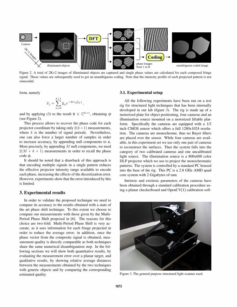
Figure 2. A total of 2K+2 images of illuminated objects are captured and single phase values are calculated for each composed fringe
signal. Those values are subsequently used to get an unambiguous coding. Note that the intensity profile of each projected pattern is not
sinusoidal.
form, namely
xj =k+1∑n=0
yne−2πi nk+1 j ,
and by applying (3) to the result x ∈ Ck+1, obtaining φ
(see Figure 2).
This process allows to recover the phase code for each
projector coordinate by taking only 2(k+1) measurements,
where k is the number of signal periods. Nevertheless,
one can also force a larger number of samples in order
to increase accuracy, by appending null components to x.
More precisely, by appending M null components, we need
2(M + k + 1) measurements in order to recall the phase
code φ.
It should be noted that a drawback of this approach is
that encoding multiple signals in a single pattern reduces
the effective projector intensity range available to encode
each phase, increasing the effects of the discretization error.
However, experiments show that the error introduced by this
is limited.
3. Experimental resultsIn order to validate the proposed technique we need to
compare its accuracy to the results obtained with a state of
the art phase shift technique. To this extent we choose to
compare our measurements with those given by the Multi-
Period Phase Shift proposed in [6]. The reasons for this
choice are two-fold: Multi-Period Phase Shift is very ac-
curate, as it uses information for each fringe projected in
order to reduce the average error; in addition, once the
phase vector from the composite signal is obtained, mea-
surement quality is directly comparable as both techniques
share the same numerical disambiguation step. In the fol-
lowing sections we will show both quantitative results, by
evaluating the measurement error over a planar target, and
qualitative results, by showing relative average distances
between the measurements obtained by the two techniques
with generic objects and by comparing the corresponding
estimated quality.
3.1. Experimental setup
All the following experiments have been run on a test
rig for structured light techniques that has been internally
developed in our lab (figure 3). The rig is made up of a
motorized plate for object positioning, four cameras and an
illumination source mounted on a motorized liftable plat-
form. Specifically the cameras are equipped with a 1/2
inch CMOS sensor which offers a full 1280x1024 resolu-
tion. The cameras are monochrome, thus no Bayer filters
are placed over the sensor. While four cameras are avail-
able, in this experiment set we use only one pair of cameras
to reconstruct the surfaces. Thus the system falls into the
category of two calibrated cameras and one uncalibrated
light source. The illumination source is a 800x600 color
DLP projector which we use to project the monochromatic
patterns. The system is controlled by a standard PC housed
into the base of the rig. This PC is a 2.8 GHz AMD quad
core system with 2 Gigabytes of ram.
Intrinsic and extrinsic parameters of the cameras have
been obtained through a standard calibration procedure us-
ing a planar checkerboard and OpenCV[1] calibration soft-
Figure 3. The general purpose structured light scanner used.
1673

26
28
30
32
34
36
38
40
8 12 16 20 24 28 32 36 40
Ave
rage
dis
tanc
e fr
om p
lane
(m
icro
ns)
Number of samples
CompoundMulti
(a)
26
28
30
32
34
36
38
40
8 12 16 20 24 28 32 36 40
Ave
rage
dis
tanc
e fr
om p
lane
(m
icro
ns)
Number of samples
CompoundMulti
(b)
Figure 4. Accuracy comparison between the Compound Phase Coding method and the Multi-Period Phase Shift technique. In figure 4(a)
we used periods of 7, 11 and 13 pixels (30 patterns for Multi-Period Phase Shift), and in figure 4(b) we used periods of length 9, 11 and
13 (34 patterns for Multi-Period Phase Shift). Note that the Multi-Period technique appears as a flat continuous red line and its standard
deviation as dashed red lines. Vertical bars are standard deviations in the measurement of the error for the compound technique.
ware. It must be noted that our system is not a full fledged
production scanner, thus it does not guarantees extreme ac-
curacy or resolution: in fact we estimate its precision in
about 30μm. This level of accuracy is adequate with respect
to our experiments, as we are not interested in showing the
absolute precision of our setup, but rather the relative per-
formance of the coding schemes, showing that the proposed
approach can be used as an effective replacement for slower
approaches without suffering from a significant loss in ac-
curacy.
3.2. Planar target measurements
In this first set of experiments we measured the surface
of a 200 by 200 mm squared piece of float glass which we
previously sprayed with a very thin layer of acrylic paint.
We made several sets of measurements with both the Com-
pound Phase Coding technique and the Multi-Period Phase
Shift technique. Since the exact pose of the test object is
unknown and the surface cannot be perfectly flat, we ap-
proximated the ground truth with the best fitting plane (in
the least squares sense) with respect to the measured points
of the object. This way we estimate the expected measure-
ment error of each technique as the average of the absolute
value of the distance from the fitting plane of each mea-
sured point. We had a wide range of choices regarding the
number of different signals to project and their periods. We
chose to execute the test with two configurations: 3 sig-
nals of periods respectively 7, 11 and 13 pixels and other
3 signals of periods 9, 11 and 13 pixels. Since our pro-
jector has an horizontal resolution of 800 pixels both con-
figurations allow to obtain a globally unambiguous coding
of the object. Given those signal configurations, we pro-
jected respectively 30 and 34 patterns for testing the Multi-
Period Phase Shift technique. Since we always used 3 sig-
nals, the Compound Phase Shift technique strictly requires
only 8 patterns to be projected: nevertheless we repeated
the measurement with a growing number of additional pat-
terns in order to study the effect of the supplementary in-
formation on the final accuracy. Finally, each experimen-
tal measure was repeated for a total of 10 times. In figure
4 we compare the performance of the proposed approach
against the baseline multi-period approach. Accuracy of
the multi-phase approach is slightly better in 4(b), proba-
bly due to the higher number of patterns projected (34 in-
stead of 30). The blue line shows the trend of the average
error of the proposed Compound Phase Coding technique
as the number of projected pattern is increased. It should be
noted that even with the minimal number of projected pat-
terns the accuracy is quite good: in fact, on average our dis-
tances from the fitting plane are only about three microme-
ters higher than those obtained using the Multi-Period tech-
nique, which requires almost four times as many patterns.
Moreover, by projecting additional patterns, the quality of
the measurements can be further enhanced: for instance, by
doubling the number of projected patterns the distance from
the Multi-Period approach is approximately halved. Finally,
as we expected, using the same number of patterns pro-
jected by the Multi-Period technique, the two approaches
yield equivalent performances. Of course, the whole point
of the proposed technique is to reduce the number of pro-
jected patterns. In this sense, our approach allows to control
the time/precision trade-off, obtaining good reconstructions
even with just 8 patterns.
1674

Cube and Disc Cone and Spheres Toy House
Technique Multi Comp 8 Comp 16 Multi Comp 8 Comp 16 Multi Comp 8 Comp 16
Captured points 109347 108306 109034 46749 46263 46505 37457 36880 37133
Average deviation 0.025 0.089 0.063 0.030 0.085 0.067 0.036 0.088 0.068
Average distance - 32.00 25.09 - 21.15 16.19 - 23.26 20.87
Figure 5. Comparison between reconstructions obtained with the Multi-Period Phase Shift and the Compound Phase Coding on several test
objects. Compound Phase Coding has been tested using both 8 and 16 samples. Multi-Period Phase Shift has been tested with 34 samples
in order to obtain the best quality. Distances are in microns and objects are 5 to 10 cm wide.
3.3. Generic objects measurements
In this set of experiments we measured the surface of
several generic scenes built with simple wooden objects in a
volume of about 200 mm of diameter in each direction. The
set of objects was selected to maximize the range of surface
orientations and conditions. Again we compared our re-
sults with those obtained by the Multi-Period approach: in
this case we take the Multi-Period results as a direct com-
parison, as no ground-truth or knowledge of the surface of
the objects (which are hand-made) is available. Compound
Phase Coding was tested both with 8 and 16 projected pat-
terns. Since we projected signals with periods of respec-
tively 9, 11 and 13 pixels Multi-Period Phase Shift was
tested with 34 samples. For each experiment we evaluated
three quantities, namely:
• The number of points acquired. That is the number of
surface points that pass both the consistency and the
quality check. The first verifies that the phase vec-
tor is consistent with the code assigned to the point,
the latter ensures that the phase difference vector con-
tains only integer values (as expected with respect to
constraint 2). Specifically, for these experiments we
rejected points associated to phase difference vectors
where at least one entry deviates from the nearest inte-
ger by more than 0.2;
• The average deviation. That is the average distance
from each entry in the phase difference vector and the
nearest integer. Since each element of the phase differ-
ence vector should be integer a lower value suggests
a higher quality in the measurement obtained. This
parameter has been calculated over all the points ob-
tained, even those filtered by the consistency and qual-
ity checks;
• The average distance. That is the average of the ab-
solute distances between points obtained by the Multi-
Period and Compound techniques. Note that this mea-
sure is possible because we implemented both algo-
rithms in a way that allowed us to produce depth maps
that are exactly overlapped along the x and y axis and
differ only for the depth values assigned along the z
axis.
In Figure 5 we report the values of those three quantities
in different scenes. In general, the number of points ac-
quired by the Compound Phase Coding with only 8 patterns
is slightly smaller than the number of valid points given by
the Multi-Period technique. This distance, while small, is
almost completely eliminated when using 16 patterns. The
average deviation resulting by applying our technique is al-
ways slightly higher, nevertheless it should be remarked that
those values are all quite small: in fact, for any practical pur-
pose a deviation smaller than 0.1 can always be associated
with a valid measured point. Finally, the average distances
between the two techniques also assess the suitability of our
technique as a fast replacement for traditional Multi-Period:
in fact, the results obtained are generally compatible with
the measurement error estimated in the experiments done in
section 3.2, a result that should be expected since both tech-
niques are subject to measurement errors. It should also
be noted that the higher average distance obtained with the
scene “Cube and Disc” is probably due to the presence of
sharp edges and of two large surfaces at a grazing angle
with both the cameras and the light source. Conversely, the
higher smoothness offered by the scene “Cone and Spheres”
allows for a more precise reconstruction.
In Figure 6 we show a more qualitative example of
the difference in accuracy of reconstruction between our
method and a complete Multi-Period phase shift. In this ex-
periment we used the less accurate instance of Compound
1675

Figure 6. A surface reconstruction example complete with deviation assessment. In the first colum, the object as viewed by the left and
right camera. In the second column, the deviance maps of Multi-Period Phase Shift (top) and Compound Phase Coding (bottom). In the
last colums, two respective close-ups of the reconstructed surfaces.
Phase Coding, thus only 8 patterns were projected. In the
first column we reproduced the scene viewed from the left
and right camera. In the second column we calculated a map
of the maximum deviation from integer values of the phase
difference vectors of the Multi-period method (top) and the
Compound method (bottom). In these maps we used the
standard Matlab color scale, thus a full blue pixel indicates
a low deviation and a bright red pixel a maximum deviation
(in this case 0.5). Uncoded pixels are represented in dark
red. Both techniques exhibit a fairly low deviation, with
high values mainly on the borders, which is due to the cam-
era integration of the projected signal and the background
on boundary pixels. The other high deviation area on the
side of the cube is probably due to inter-reflection between
the two objects.
The last two columns show a close-up of the surfaces
reconstructed with both methods. In general the surface
reconstructed with the Compound technique is a bit more
noisy, but the overall level of detail is maintained, even with
details at a relatively high frequency being clearly visible
on both reconstructions: for instance, in the close-up of the
disc object (third column) a very small bulge is visible in
both the reconstructions in proximity of the lower rim of
the hemisphere.
Finally, in Figure 7, we compare the reconstructed
phases obtained after the application of the Discrete Fourier
Transform to the captured structured light images before
and after the coding step. As in the previous experiments
we choose periods of 9, 10 and 13 pixels and we projected
34 patterns for the Multi-Period method and 8 pattern for
our approach. In the first column we show respectively the
complete coding for the Multi-Period (top) and for the Com-
pound (middle) methods. In order to highlight the differ-
ences between the two codings, we show in the third line
of this column the difference image between them: as ex-
pected they are almost identical and the only slight differ-
ences are found in boundary regions, where the measure-
ments are less precise.
In the other two columns we show the phase related to
two different signals calculated by the two techniques (we
show only two signals for space reasons). For the purpose of
a simple comparison between them, we plotted a magnified
graph of the small red lines in the phase images. In those
graphs the red line represents the phase extracted by the
Multi-Period method and the blue line the phase extracted
by our technique. It can be seen that the values obtained are
very similar, and that they diverge by a very small amount
only in proximity of critical areas such as the interface be-
tween the disc and the hemisphere.
4. ConclusionsIn this paper we have proposed a novel compound phase
coding technique that is able to perform a complete and ac-
curate surface reconstruction requiring the projection of as
few as 8 patterns. This is obtained by encoding multiple
phase information in a single pattern sequence as phases
of sinusoidal signals at integer frequencies, thus encoding
and decoding the compound signal using standard Fourier
analysis. The comparison with another well known tech-
nique assesses the ability of the approach to obtain accu-
rate reconstruction even with very few patterns. In addi-
tion, the time/quality trade-off can be easily controlled by
adding more patterns. In fact, we show that measurement
error decreases consistently by adding more information, to
the point that our method reaches the performance of other
state-of-the-art approaches when feeded with a comparable
quantity of data.
1676

Figure 7. A comparison of the coding and of the phase values extracted by our technique and by Multi-Period phase shift. In the first colum
we show the final codings and their difference. In the other columns we display the respective phase images for two reconstructed signals.
The two magnified plots in the last row correspond to the small red segment. Note that the obtained phases are very similar even in the
proximity of critical areas.
References[1] G. Bradski and A. Kaehler. Learning OpenCV: Computer
Vision with the OpenCV Library. O’Reilly Media, Inc., 1st
edition, October 2008.
[2] W. Chen, H. Yang, X. Su, and S. Tan. Error caused by sam-
pling in fourier transform profilometry. Optical Engineering,
38(6):1029–1034, 1999.
[3] C. Guan, L. Hassebrook, and D. Lau. Composite struc-
tured light pattern for three-dimensional video. Opt. Express,
11(5):406–417, 2003.
[4] E. M. M. Joan Batlle and J. Salvi. Recent progress in coded
structured light as a technique to solve the correspondence
problem: a survey. Pattern Recognition, 31(7):963–982,
1998.
[5] J. P. Joaquim Salvi and J. Batlle. Pattern codification
strategies in structured light systems. Pattern Recognition,
37:827–849, 2004.
[6] E. Lilienblum and B. Michaelis. Optical 3d surface re-
construction by a multi-period phase shift method. JCP,
2(2):73–83, 2007.
[7] D. Scharstein and R. Szeliski. A taxonomy and evaluation of
dense two-frame stereo correspondence algorithm. Int. J. of
Comp. Vision, 47(1):7–42, 2002.
[8] V. Srinivasan, H. C. Liu, and M. Halioua. Automated phase-
measuring profilometry: a phase mapping approach. Appl.Opt., 24(2):185–188, 1985.
[9] X. Su and W. Chen. Fourier transform profilometry: a re-
view. Optics and Lasers in Engineering, 35:263–284, May
2001.
[10] Y. Surrel. Design of algorithms for phase measurements by
the use of phase stepping. Appl. Opt., 35(1):51–60, 1996.
[11] M. Takeda and K. Mutoh. Fourier transform profilometry for
the automatic measurement of 3-d object shapes. Appl. Opt.,22(24):3977–3982, 1983.
[12] C. Xiaobo, X. J. tong, J. Tao, and J. Ye. Research and devel-
opment of an accurate 3d shape measurement system based
on fringe projection: Model analysis and performance eval-
uation. Precision Engineering, 32(3):215 – 221, 2008.
[13] H.-M. Yue, X.-Y. Su, and Y.-Z. Liu. Fourier transform pro-
filometry based on composite structured light pattern. OpticsLaser Technology, 39:1170–1175, Sept. 2007.
[14] J. Zhong and Y. Zhang. Absolute phase-measurement tech-
nique based on number theory in multifrequency grating pro-
jection profilometry. Appl. Opt., 40(4):492–500, 2001.
1677