error coding - asecuritysite.com
TRANSCRIPT
5 Error Coding
5.1 Error coding principles
The data transmitted over communications channels, and the Internet must be protected
against or be able to detect errors. Error bits are added to data either to correct or to detect
transmission errors. Normally, the more bits that are added, the better the correction or detec-
tion. Error detection allows the receiver to determine if there has been a transmission error. It
cannot rebuild the correct data and must either request a retransmission or discard the data.
With error correction, the receiver detects an error and tries to correct as many error bits as
possible. Again, the more error coding bits are used, the more bits can be corrected. An error
correction code is normally used when the receiver cannot request a retransmission.
In a digital communication system, a single transmission symbol can actually contain
many bits. If a single symbol can represent M values then it is described as an M-ary digit.
An example of this is in modem communication where 2 bits are sent as four different phase
shifts, e.g. 0 for 00, 90 for 01, 180 for 10 and 270 for 11. To avoid confusion in this
chapter, it is assumed that the digits input to the digital coder and the digital decoder are bi-
nary digits, and this chapter does not deal with M-ary digits.
5.1.1 Modulo-2 arithmetic
Digital coding uses modulo-2 arithmetic where addition becomes the following operations:
0 + 0 = 0 1 + 1 = 0
0 + 1 = 1 1 + 0 = 1
It performs the equivalent operation to an exclusive-OR (XOR) function. For modulo-2
arithmetic, subtraction is the same operation as addition:
0 – 0 = 0 1 – 1 = 0
0 – 1 = 1 1 – 0 = 1
Multiplication is performed with the following:
0 0 = 0 0 1 = 0
1 0 = 0 1 1 = 1
which is an equivalent operation to a logical AND operation.
5.1.2 Binary manipulation
Binary digit representation, such as 101110, is difficult to use when multiplying and divid-
ing. A typical representation is to manipulate the binary value as a polynomial of bit powers.
This technique represents each bit as an x to the power of the bit position and then adds each
of the bits. For example:
2 Telecommunications
10111 x4+x2+x+1
1000 0001 x7+ 1
1111 1111 1111 1111 x11+x10+x9+x8+x7+x6+x5+x4+x3+x2+x+1
10101010 x7+x5+x3+x
For example: 101110
is represented as: (x2+1)(x2+x)
which equates to: x4+x3+x2+x
which is thus: 11110
Check here: http://www.asecuritysite.com/calculators/mod2?a=101&b=110
The addition of the bits is treated as a modulo-2 addition, that is, any two values which have
the same powers are equal to zero. For example:
x4+x4+x2+1+1
is equal to x2 as x4+x4 is equal to zero and 1+1 is equal to 0 (in modulo-2). An example which
shows this is the multiplication of 10101 by 01100.
Thus: 1010101110
is represented as: (x4+x2+1)(x3+x2+x)
which equates to: x7+x6+x5+x5+x4+x3+x3+x2+x
which equates to: x7+x6+x4+x2+x
which is thus: 11010110
Check here: http://www.asecuritysite.com/calculators/mod2?a=10101&b=01110
This type of multiplication is easy to implement as it just involves AND and XOR opera-
tions.
The division process uses exclusive-OR operation instead of subtraction and can be
implemented with a shift register and a few XOR gates. For example, 101101 divided by 101
is implemented as follows:
1011
100 101101
100
110
100
101
100
1
Thus, the modulo-2 division of 101101 by 100 is 1011 remainder 1. As with multiplication,
this modulo-2 division can also be represented with polynomial values.
Check here: http://www.asecuritysite.com/calculators/mod_div?a=101101&b=100
Error coding 3
Normally, pure integer or floating-point multiplication and division require complex
hardware and can cause a considerable delay in computing the result. Error coding multipli-
cation and division circuits normally use a modified version of multiplication and division,
which uses XOR operations and shift registers.
5.1.3 Hamming distance
The Hamming distance, d(C1,C2), between two code words C1 and C2 is defined as the num-
ber of places in which they differ. For example, the codes:
101101010 and 011101100
have a Hamming distance of 4 as they differ in 4 bit positions. Also d(11111,00000) is equal
to 5.
The Hamming distance can be used to determine how well the code will cope with errors.
The minimum Hamming distance min{d(C1,C2)} defines by how many bits the code must
change so that one code can become another code.
It can be shown that:
A code C can detect up to N errors for any code word if d(C) is greater than or equal to
N+1 (that is, d(C)N+1).
A code C can correct up to M errors in any code word if d(C) is greater than or equal to
2M+1 (that is, d(C)2M+1).
For example the code:
{00000, 01101, 10110, 11011}
has a minimum Hamming distance of 3. Thus, the number of errors which can be detected is
given by:
d(C)N+1
since, in this case, d(C) is 3 then N must be 2. This means that one or two errors in the code
word will be detected as an error. For example, the following have 2 bits in error, and will
thus be received as an error:
00011, 10101, 11010, 00011
The number of errors which can be corrected (M) is given by:
d(C)2M+1
thus M will be 1, which means that only one bit in error can be corrected. For example if the
received code word was:
01111
then this code is measured against all the other codes and the Hamming distance calculated.
4 Telecommunications
Thus 00000 has a Hamming distance of 4, 01101 has a Hamming distance of 1, 10110 has a
Hamming distance of 3, and 11011 has a Hamming distance of 2. Thus, the received code is
nearest to 01101. Linear and cyclic codes
A linear binary code is one in which the sum of any two code words is also a code word. For
example:
{00, 01, 10, 11} and {00000, 01101, 10110, 11011}
are linear codes, because any of the code words added (using modulo-2 addition) to another
gives another valid code word. For example, in the second code, 01101 + 10110 gives 11011,
which is a valid code word.
Cyclic codes often involve complex mathematics but are extremely easy to implement
with XOR gates and shift registers. A code is cyclic if:
It is a linear code.
When any cyclic shift of a code word is also a code word, i.e. whenever a0a1 … an–1 is a
code word then so is an–1a0a1 … an–2.
For example, the code {0000, 0110, 0011, 1001, 1100, 0001, 0010, 0100, 1000} is cyclic
because a shift in the bits, either left or right, produces a valid code word. Whereas the code
{000, 010, 011, 100, 001} is not cyclic as a shift in the code word 011 to the left or right
does not result in a valid code word. One of the most widely used codes, cyclic redundancy
check (CRC) is an example of a cyclic code.
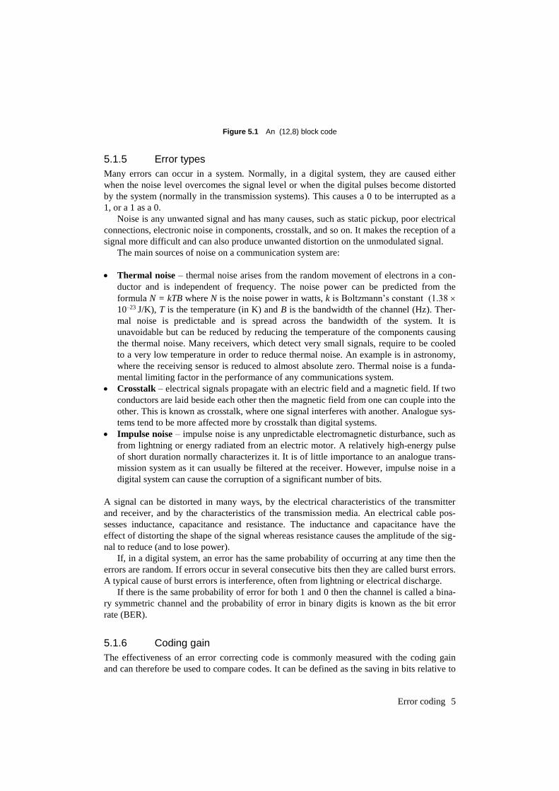
5.1.4 Block and convolutional coding
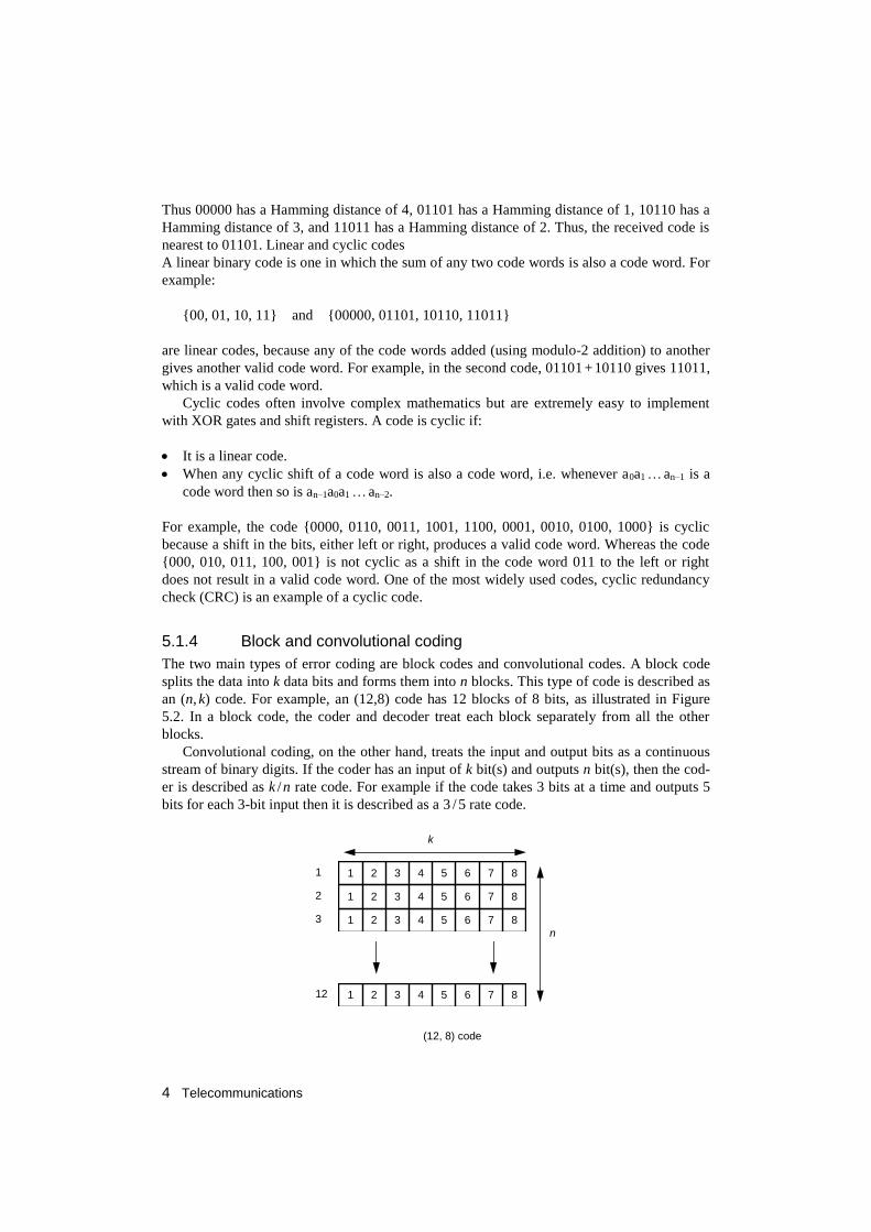
The two main types of error coding are block codes and convolutional codes. A block code
splits the data into k data bits and forms them into n blocks. This type of code is described as
an (n, k) code. For example, an (12,8) code has 12 blocks of 8 bits, as illustrated in Figure
5.2. In a block code, the coder and decoder treat each block separately from all the other
blocks.
Convolutional coding, on the other hand, treats the input and output bits as a continuous
stream of binary digits. If the coder has an input of k bit(s) and outputs n bit(s), then the cod-
er is described as k /n rate code. For example if the code takes 3 bits at a time and outputs 5
bits for each 3-bit input then it is described as a 3 / 5 rate code.
1 2 3 4 5 6 7 8
1 2 3 4 5 6 7 8
1 2 3 4 5 6 7 8
1 2 3 4 5 6 7 8
1
2
3
12
(12, 8) code
n
k
Error coding 5
Figure 5.1 An (12,8) block code
5.1.5 Error types
Many errors can occur in a system. Normally, in a digital system, they are caused either
when the noise level overcomes the signal level or when the digital pulses become distorted
by the system (normally in the transmission systems). This causes a 0 to be interrupted as a
1, or a 1 as a 0.
Noise is any unwanted signal and has many causes, such as static pickup, poor electrical
connections, electronic noise in components, crosstalk, and so on. It makes the reception of a
signal more difficult and can also produce unwanted distortion on the unmodulated signal.
The main sources of noise on a communication system are:
Thermal noise – thermal noise arises from the random movement of electrons in a con-
ductor and is independent of frequency. The noise power can be predicted from the
formula N = kTB where N is the noise power in watts, k is Boltzmann’s constant (1.38
10–23 J/K), T is the temperature (in K) and B is the bandwidth of the channel (Hz). Ther-
mal noise is predictable and is spread across the bandwidth of the system. It is
unavoidable but can be reduced by reducing the temperature of the components causing
the thermal noise. Many receivers, which detect very small signals, require to be cooled
to a very low temperature in order to reduce thermal noise. An example is in astronomy,
where the receiving sensor is reduced to almost absolute zero. Thermal noise is a funda-
mental limiting factor in the performance of any communications system.
Crosstalk – electrical signals propagate with an electric field and a magnetic field. If two
conductors are laid beside each other then the magnetic field from one can couple into the
other. This is known as crosstalk, where one signal interferes with another. Analogue sys-
tems tend to be more affected more by crosstalk than digital systems.
Impulse noise – impulse noise is any unpredictable electromagnetic disturbance, such as
from lightning or energy radiated from an electric motor. A relatively high-energy pulse
of short duration normally characterizes it. It is of little importance to an analogue trans-
mission system as it can usually be filtered at the receiver. However, impulse noise in a
digital system can cause the corruption of a significant number of bits.
A signal can be distorted in many ways, by the electrical characteristics of the transmitter
and receiver, and by the characteristics of the transmission media. An electrical cable pos-
sesses inductance, capacitance and resistance. The inductance and capacitance have the
effect of distorting the shape of the signal whereas resistance causes the amplitude of the sig-
nal to reduce (and to lose power).
If, in a digital system, an error has the same probability of occurring at any time then the
errors are random. If errors occur in several consecutive bits then they are called burst errors.
A typical cause of burst errors is interference, often from lightning or electrical discharge.
If there is the same probability of error for both 1 and 0 then the channel is called a bina-
ry symmetric channel and the probability of error in binary digits is known as the bit error
rate (BER).
5.1.6 Coding gain
The effectiveness of an error correcting code is commonly measured with the coding gain
and can therefore be used to compare codes. It can be defined as the saving in bits relative to
6 Telecommunications
an uncoded system delivering the same bit error rate.
5.2 Error correction
The most important measure of error detection is the Hamming distance. This defines the
number of changes in the transmitted bits that are required in order for a code word to be
received as another code word. The more bits that are added, the greater the Hamming dis-
tance can be, and the objective of a good error detecting code is to be able to maximize the
minimum Hamming distance between codes. For example, a code which has a minimum
Hamming distance of 1 cannot be used to detect errors. This is because a single error in a
specific bit in one or more code words causes the received code word to be received as a
valid code word. A minimum Hamming distance of 2 will allow one error to be detected. In
general, a code C can detect up to N errors for any code word if d(C) is greater than or equal
to N + 1 (i.e. d(C)N + 1). For this it can be shown that:
The number of errors detected = d-1
where d is the minimum Hamming distance.
Error detection allows the receiver to determine if there has been a transmission error. It
cannot rebuild the correct data and must either request a retransmission or discard the data.
5.2.1 Parity
Simple parity adds a single parity bit to each block of transmitted symbols. This parity bit
either makes them have an even number of 1’s (even parity) or an odd number of 1’s (odd
parity). It is a simple method of error detection and requires only exclusive-OR (XOR) gates
to generate the parity bit. This output can be easily added to the data using a shift register.
Parity bits can only detect an odd number of errors, i.e. 1, 3, 5, and so on. If an even
number of bits is in error then the parity bit will be correct and no error will be detected. This
type of coding is normally not used on its own or where there is the possibility of several bits
being in error.
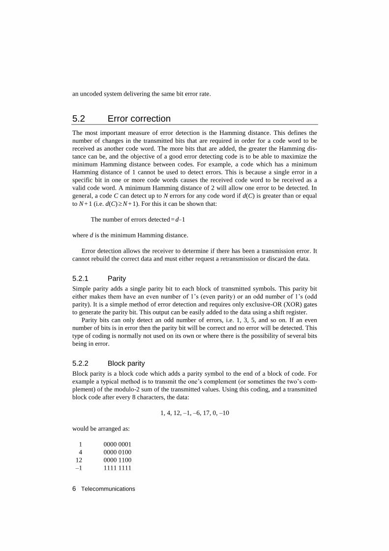
5.2.2 Block parity
Block parity is a block code which adds a parity symbol to the end of a block of code. For
example a typical method is to transmit the one’s complement (or sometimes the two’s com-
plement) of the modulo-2 sum of the transmitted values. Using this coding, and a transmitted
block code after every 8 characters, the data:
1, 4, 12, –1, –6, 17, 0, –10
would be arranged as:
1 0000 0001
4 0000 0100
12 0000 1100
–1 1111 1111
Error coding 7
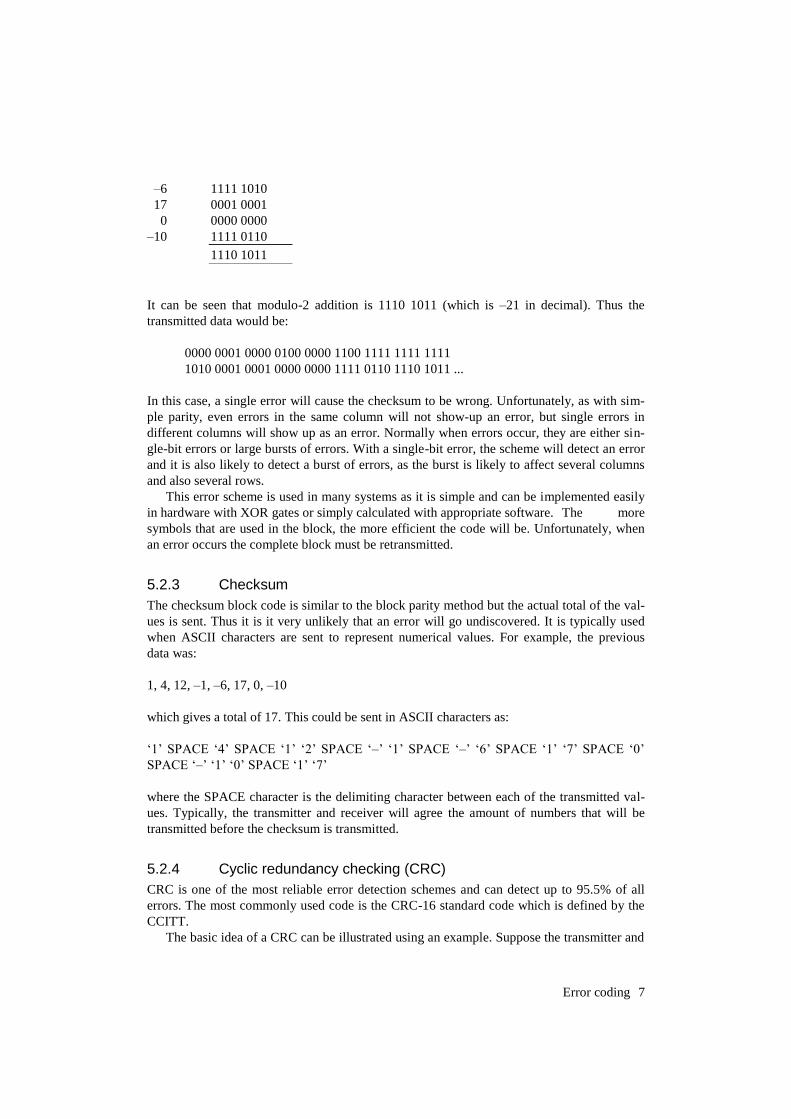
–6 1111 1010
17 0001 0001
0 0000 0000
–10 1111 0110
1110 1011
It can be seen that modulo-2 addition is 1110 1011 (which is –21 in decimal). Thus the
transmitted data would be:
0000 0001 0000 0100 0000 1100 1111 1111 1111
1010 0001 0001 0000 0000 1111 0110 1110 1011 ...
In this case, a single error will cause the checksum to be wrong. Unfortunately, as with sim-
ple parity, even errors in the same column will not show-up an error, but single errors in
different columns will show up as an error. Normally when errors occur, they are either sin-
gle-bit errors or large bursts of errors. With a single-bit error, the scheme will detect an error
and it is also likely to detect a burst of errors, as the burst is likely to affect several columns
and also several rows.
This error scheme is used in many systems as it is simple and can be implemented easily
in hardware with XOR gates or simply calculated with appropriate software. The more
symbols that are used in the block, the more efficient the code will be. Unfortunately, when
an error occurs the complete block must be retransmitted.
5.2.3 Checksum
The checksum block code is similar to the block parity method but the actual total of the val-
ues is sent. Thus it is it very unlikely that an error will go undiscovered. It is typically used
when ASCII characters are sent to represent numerical values. For example, the previous
data was:
1, 4, 12, –1, –6, 17, 0, –10
which gives a total of 17. This could be sent in ASCII characters as:
‘1’ SPACE ‘4’ SPACE ‘1’ ‘2’ SPACE ‘–’ ‘1’ SPACE ‘–’ ‘6’ SPACE ‘1’ ‘7’ SPACE ‘0’
SPACE ‘–’ ‘1’ ‘0’ SPACE ‘1’ ‘7’
where the SPACE character is the delimiting character between each of the transmitted val-
ues. Typically, the transmitter and receiver will agree the amount of numbers that will be
transmitted before the checksum is transmitted.
5.2.4 Cyclic redundancy checking (CRC)
CRC is one of the most reliable error detection schemes and can detect up to 95.5% of all
errors. The most commonly used code is the CRC-16 standard code which is defined by the
CCITT.
The basic idea of a CRC can be illustrated using an example. Suppose the transmitter and
8 Telecommunications
receiver were both to agree that the numerical value sent by the transmitter would always be
divisible by 9. Then should the receiver get a value which was not divisible by 9 would know
it knows that there had been an error. For example, if a value of 32 were to be transmitted it
could be changed to 320 so that the transmitter would be able to add to the least significant
digit, making it divisible by 9. In this case the transmitter would add 4, making 324. If this
transmitted value were to be corrupted in transmission then there would only be a 10%
chance that an error would not be detected.
In CRC-CCITT, the error correction code is 16 bits long and is the remainder of the data
message polynomial G(x) divided by the generator polynomial P(x) (x16+x12+x5+1, i.e.
10001000000100001). The quotient is discarded and the remainder is truncated to 16 bits.
This is then appended to the message as the coded word.
The division does not use standard arithmetic division. Instead of the subtraction
operation an exclusive-OR operation is employed. This is a great advantage as the CRC only
requires a shift register and a few XOR gates to perform the division.
The receiver and the transmitter both use the same generating function P(x). If there are
no transmission errors then the remainder will be zero.
The method used is as follows:
1. Let P(x) be the generator polynomial and M(x) the message polynomial.
2. Let n be the number of bits in P(x).
3. Append n zero bits onto the right-hand side of the message so that it contains m+n bits.
4. Using modulo-2 division, divide the modified bit pattern by P(x). Modulo-2 arithmetic
involves exclusive-OR operations, i.e. 0-1=1, 1-1=0, 1-0=1 and 0-0=0.
5. The final remainder is added to the modified bit pattern.
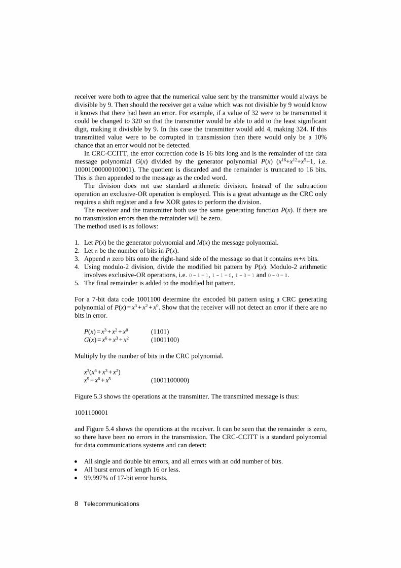
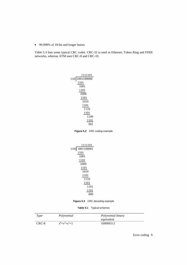
For a 7-bit data code 1001100 determine the encoded bit pattern using a CRC generating
polynomial of P(x) = x3 + x2 + x0. Show that the receiver will not detect an error if there are no
bits in error.
P(x) = x3 + x2 + x0 (1101)
G(x) = x6 + x3 + x2 (1001100)
Multiply by the number of bits in the CRC polynomial.
x3(x6 + x3 + x2)
x9 + x6 + x5 (1001100000)
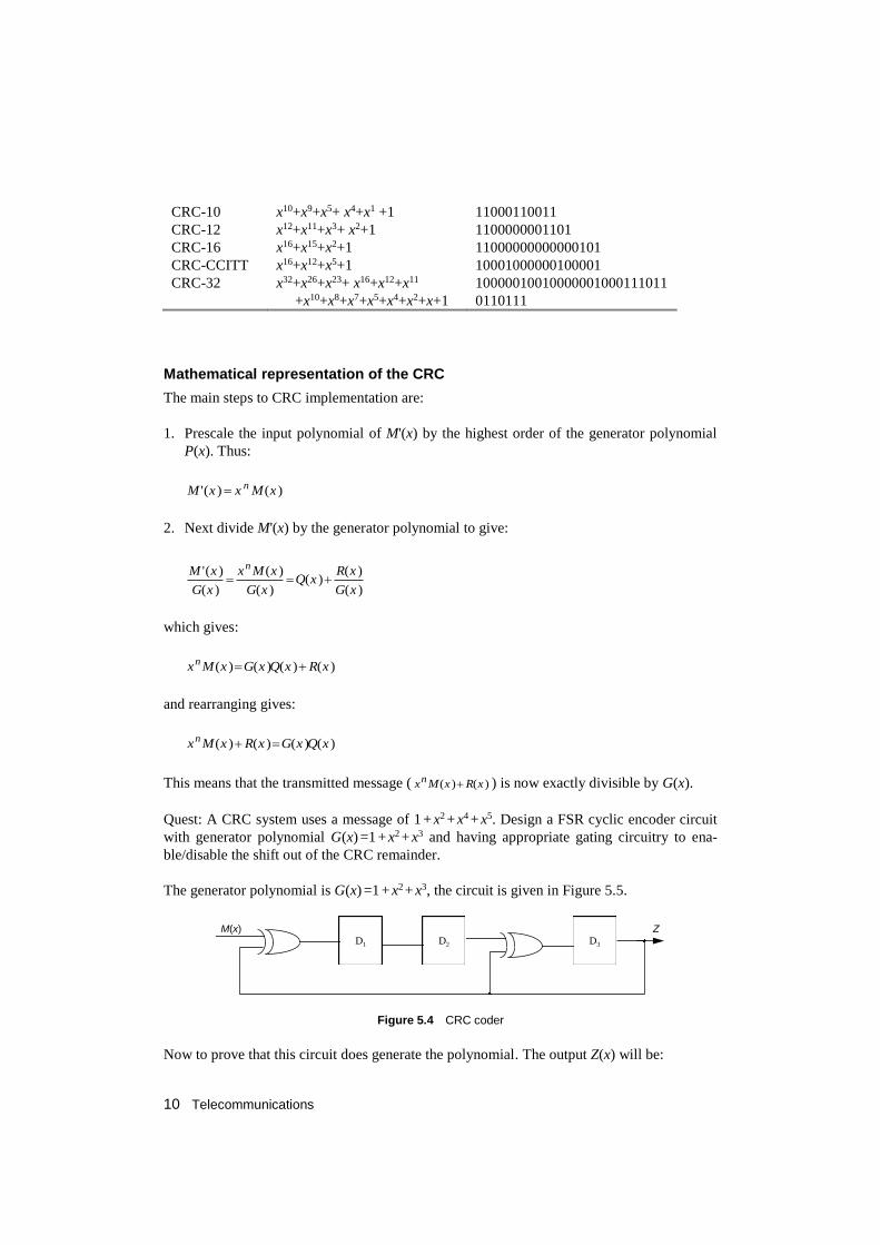
Figure 5.3 shows the operations at the transmitter. The transmitted message is thus:
1001100001
and Figure 5.4 shows the operations at the receiver. It can be seen that the remainder is zero,
so there have been no errors in the transmission. The CRC-CCITT is a standard polynomial
for data communications systems and can detect:
All single and double bit errors, and all errors with an odd number of bits.
All burst errors of length 16 or less.
99.997% of 17-bit error bursts.
Error coding 9
99.998% of 18-bit and longer bursts.
Table 5.3 lists some typical CRC codes. CRC-32 is used in Ethernet, Token Ring and FDDI
networks, whereas ATM uses CRC-8 and CRC-10.
1111101
11011001100000
1101
1001
1101
1000
1101
1010
1101
1110
1101
1100
1101
001
Figure 5.2 CRC coding example
1111101
1101 1001100001
1101
1001
1101
1000
1101
1010
1101
1110
1101
1101
1101
000
Figure 5.3 CRC decoding example
Table 5.1 Typical schemes
Type Polynomial Polynomial binary
equivalent
CRC-8 x8+x2+x1+1 100000111
10 Telecommunications
CRC-10 x10+x9+x5+ x4+x1 +1 11000110011
CRC-12 x12+x11+x3+ x2+1 1100000001101
CRC-16 x16+x15+x2+1 11000000000000101
CRC-CCITT x16+x12+x5+1 10001000000100001
CRC-32 x32+x26+x23+ x16+x12+x11
+x10+x8+x7+x5+x4+x2+x+1
10000010010000001000111011
0110111
Mathematical representation of the CRC
The main steps to CRC implementation are:
1. Prescale the input polynomial of M'(x) by the highest order of the generator polynomial
P(x). Thus:
)()(' xMxxM n
2. Next divide M'(x) by the generator polynomial to give:
)(
)()(
)(
)(
)(
)('
xG
xRxQ
xG
xMx
xG
xM n
which gives:
)()()()( xRxQxGxMxn
and rearranging gives:
)()()()( xQxGxRxMxn
This means that the transmitted message ( )()( xRxMxn ) is now exactly divisible by G(x).
Quest: A CRC system uses a message of 1 + x2 + x4 + x5. Design a FSR cyclic encoder circuit
with generator polynomial G(x) =1 + x2 + x3 and having appropriate gating circuitry to ena-
ble/disable the shift out of the CRC remainder.
The generator polynomial is G(x) =1 + x2 + x3, the circuit is given in Figure 5.5.
D1 D2 D3
M(x) Z
Figure 5.4 CRC coder
Now to prove that this circuit does generate the polynomial. The output Z(x) will be:
Error coding 11
313
1221
)()(
)()()()(
xxMxxxZ
xxxZxxMxxZxZ
Thus:
3
311)()(
x
xxxZxM
giving:
1)(
)()( 23 xx
xZ
xMxP
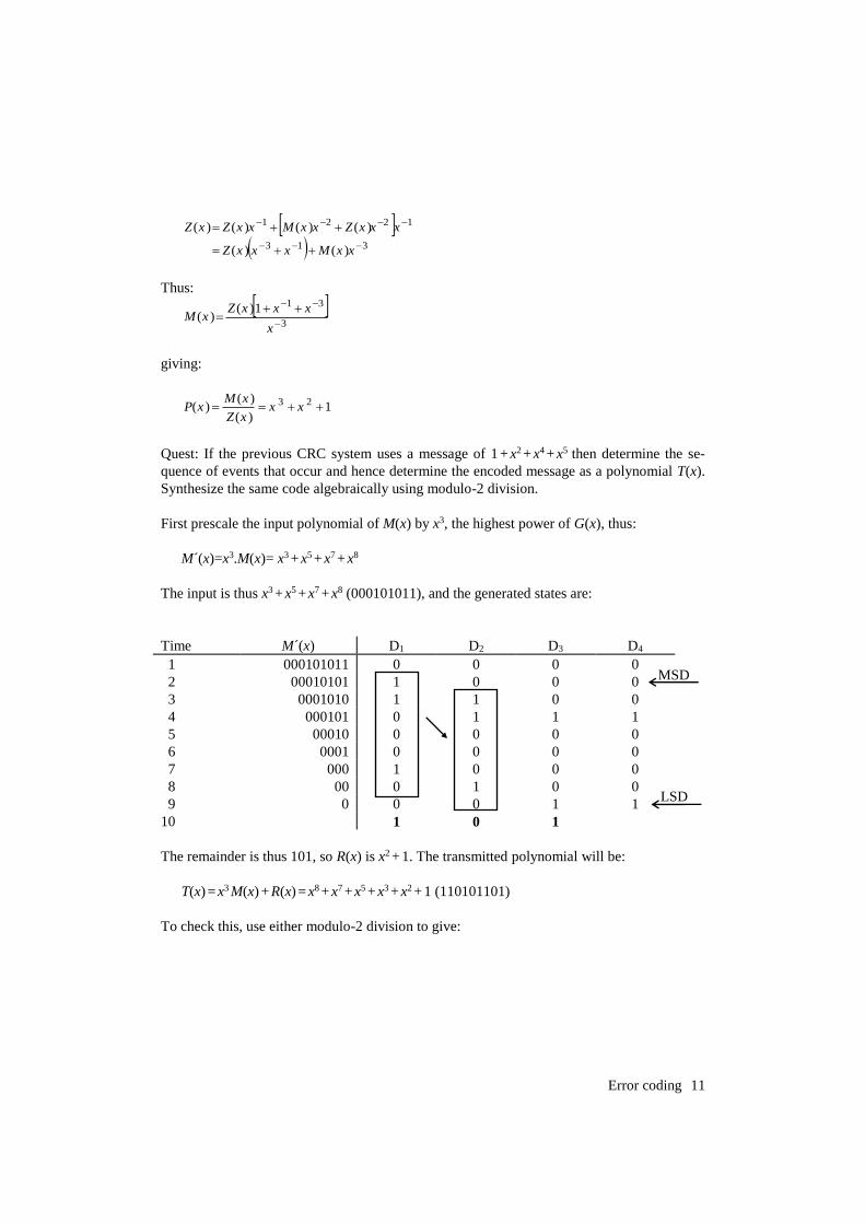
Quest: If the previous CRC system uses a message of 1 + x2 + x4 + x5 then determine the se-
quence of events that occur and hence determine the encoded message as a polynomial T(x).
Synthesize the same code algebraically using modulo-2 division.
First prescale the input polynomial of M(x) by x3, the highest power of G(x), thus:
M´(x)=x3.M(x)= x3 + x5 + x7 + x8
The input is thus x3 + x5 + x7 + x8 (000101011), and the generated states are:
Time M´(x) D1 D2 D3 D4
1 000101011 0 0 0 0
2 00010101 1 0 0 0
3 0001010 1 1 0 0
4 000101 0 1 1 1
5 00010 0 0 0 0
6 0001 0 0 0 0
7 000 1 0 0 0
8 00 0 1 0 0
9 0 0 0 1 1
10 1 0 1
The remainder is thus 101, so R(x) is x2 + 1. The transmitted polynomial will be:
T(x) = x3 M(x) + R(x) = x8 + x7 +x5 + x3 + x2 + 1 (110101101)
To check this, use either modulo-2 division to give:
LSD
MSD
12 Telecommunications
x3x21 x8x7x5x3
x8x7x5
x3
x3x21
x21
x5 +1
Remainder
This gives the same answer as the state table, i.e. x2+1.
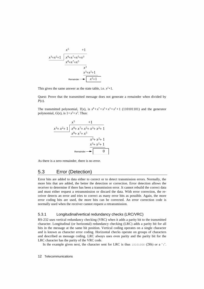
Quest: Prove that the transmitted message does not generate a remainder when divided by
P(x).
The transmitted polynomial, T(x), is x8 + x7 + x5 + x3 + x2 + 1 (110101101) and the generator
polynomial, G(x), is 1+ x2+ x3. Thus:
x3 x2 1 x8 x7 x5 x3 x2 1
x8 x7 x5
x3 x2 1
x3 x2 1
0
x5 +1
Remainder
As there is a zero remainder, there is no error.
5.3 Error (Detection)
Error bits are added to data either to correct or to detect transmission errors. Normally, the
more bits that are added, the better the detection or correction. Error detection allows the
receiver to determine if there has been a transmission error. It cannot rebuild the correct data
and must either request a retransmission or discard the data. With error correction, the re-
ceiver detects an error and tries to correct as many error bits as possible. Again, the more
error coding bits are used, the more bits can be corrected. An error correction code is
normally used when the receiver cannot request a retransmission.
5.3.1 Longitudinal/vertical redundancy checks (LRC/VRC)
RS-232 uses vertical redundancy checking (VRC) when it adds a parity bit to the transmitted
character. Longitudinal (or horizontal) redundancy checking (LRC) adds a parity bit for all
bits in the message at the same bit position. Vertical coding operates on a single character
and is known as character error coding. Horizontal checks operate on groups of characters
and described as message coding. LRC always uses even parity and the parity bit for the
LRC character has the parity of the VRC code.
In the example given next, the character sent for LRC is thus 10101000 (28h) or a ‘(’.
Error coding 13
The message sent is ‘F’, ‘r’, ‘e’, ‘d’, ‘d’, ‘y’ and ‘(’.
Without VRC checking, LRC checking detects most errors but does not detect errors
where an even number of characters have an error in the same bit position. In the previous
example if bit 2 of the ‘F’ and ‘r’ were in error then LRC would be valid.
This problem is overcome if LRC and VRC are used together. With VRC/LRC the only
time an error goes undetected is when an even number of bits, in an even number of charac-
ters, in the same bit positions of each character are in error. This is of course very unlikely.
On systems where only single-bit errors occur, the LRC/VRC method can be used to de-
tect and correct the single-bit error. For systems where more than one error can occur it is not
possible to locate the bits in error, so the receiver prompts the transmitter to retransmit the
message.
Example
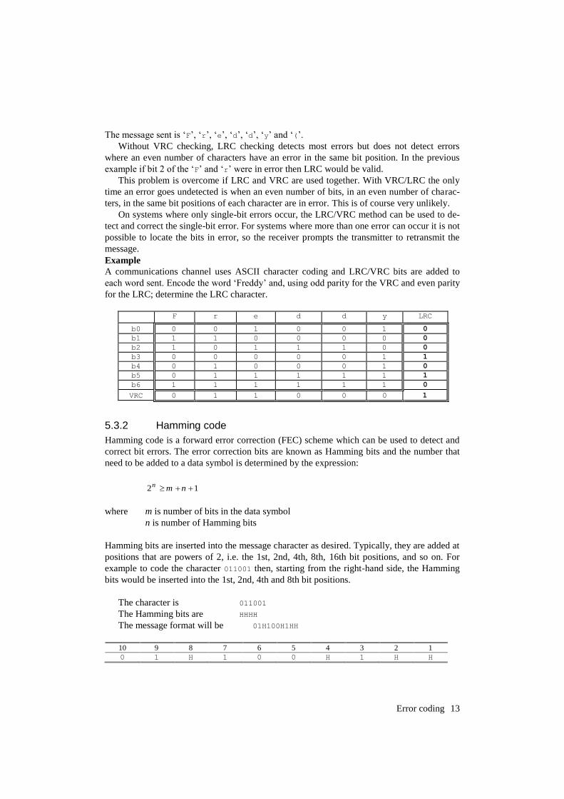
A communications channel uses ASCII character coding and LRC/VRC bits are added to
each word sent. Encode the word ‘Freddy’ and, using odd parity for the VRC and even parity
for the LRC; determine the LRC character.
F r e d d y LRC
b0 0 0 1 0 0 1 0
b1 1 1 0 0 0 0 0
b2 1 0 1 1 1 0 0
b3 0 0 0 0 0 1 1
b4 0 1 0 0 0 1 0
b5 0 1 1 1 1 1 1
b6 1 1 1 1 1 1 0
VRC 0 1 1 0 0 0 1
5.3.2 Hamming code
Hamming code is a forward error correction (FEC) scheme which can be used to detect and
correct bit errors. The error correction bits are known as Hamming bits and the number that
need to be added to a data symbol is determined by the expression:
12 nmn
where m is number of bits in the data symbol
n is number of Hamming bits
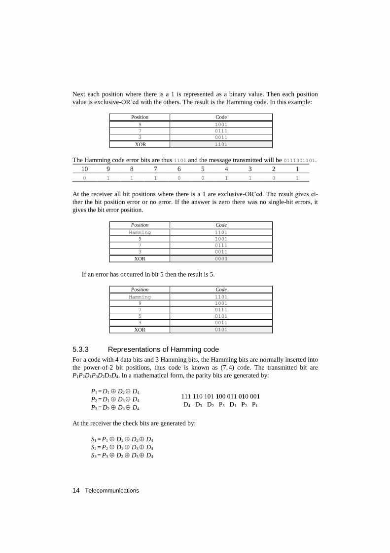
Hamming bits are inserted into the message character as desired. Typically, they are added at
positions that are powers of 2, i.e. the 1st, 2nd, 4th, 8th, 16th bit positions, and so on. For
example to code the character 011001 then, starting from the right-hand side, the Hamming
bits would be inserted into the 1st, 2nd, 4th and 8th bit positions.
The character is 011001
The Hamming bits are HHHH
The message format will be 01H100H1HH
10 9 8 7 6 5 4 3 2 1
0 1 H 1 0 0 H 1 H H
14 Telecommunications
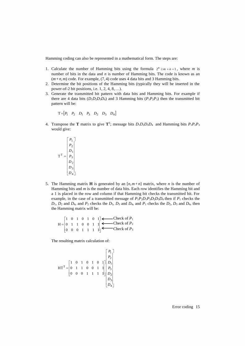
Next each position where there is a 1 is represented as a binary value. Then each position
value is exclusive-OR’ed with the others. The result is the Hamming code. In this example:
Position Code
9 1001
7 0111
3 0011
XOR 1101
The Hamming code error bits are thus 1101 and the message transmitted will be 0111001101.
10 9 8 7 6 5 4 3 2 1
0 1 1 1 0 0 1 1 0 1
At the receiver all bit positions where there is a 1 are exclusive-OR’ed. The result gives ei-
ther the bit position error or no error. If the answer is zero there was no single-bit errors, it
gives the bit error position.
Position Code
Hamming 1101
9 1001
7 0111
3 0011
XOR 0000
If an error has occurred in bit 5 then the result is 5.
Position Code
Hamming 1101
9 1001
7 0111
5 0101
3 0011
XOR 0101
5.3.3 Representations of Hamming code
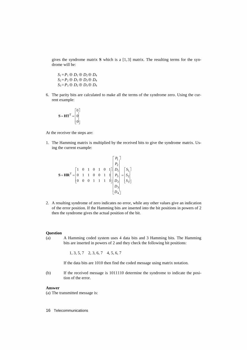
For a code with 4 data bits and 3 Hamming bits, the Hamming bits are normally inserted into
the power-of-2 bit positions, thus code is known as (7, 4) code. The transmitted bit are
P1P2D1P3D2D3D4. In a mathematical form, the parity bits are generated by:
P1 = D1 D2 D4
P2 = D1 D3 D4
P3 = D2 D3 D4
At the receiver the check bits are generated by:
S1 = P1 D1 D2 D4
S2 = P2 D1 D3 D4
S3 = P3 D2 D3 D4
D4 D3 D2 P3 D1 P2 P1
111 110 101 100 011 010 001
Error coding 15
Hamming coding can also be represented in a mathematical form. The steps are:
1. Calculate the number of Hamming bits using the formula 12 nmn , where m is
number of bits in the data and n is number of Hamming bits. The code is known as an
(m + n, m) code. For example, (7, 4) code uses 4 data bits and 3 Hamming bits.
2. Determine the bit positions of the Hamming bits (typically they will be inserted in the
power-of-2 bit positions, i.e. 1, 2, 4, 8, …).
3. Generate the transmitted bit pattern with data bits and Hamming bits. For example if
there are 4 data bits (D1D2D3D4) and 3 Hamming bits (P1P2P3) then the transmitted bit
pattern will be:
4323121T DDDPDPP
4. Transpose the T matrix to give TT; message bits D1D2D3D4 and Hamming bits P1P2P3
would give:
4
3
2
3
1
2
1
T
D
D
D
P
D
P
P
T
5. The Hamming matrix H is generated by an [n, m + n] matrix, where n is the number of
Hamming bits and m is the number of data bits. Each row identifies the Hamming bit and
a 1 is placed in the row and column if that Hamming bit checks the transmitted bit. For
example, in the case of a transmitted message of P1P2D1P3D2D3D4 then if P1 checks the
D1, D2 and D4, and P2 checks the D1, D3 and D4, and P1 checks the D2, D3 and D4, then
the Hamming matrix will be:
1111000
1100110
1010101
H
The resulting matrix calculation of:
4
3
2
3
1
2
1
1111000
1100110
1010101
HT
D
D
D
P
D
P
P
T
Check of P1
Check of P2
Check of P3
16 Telecommunications
gives the syndrome matrix S which is a [1, 3] matrix. The resulting terms for the syn-
drome will be:
S1 = P1 D1 D2 D4
S2 = P2 D1 D3 D4
S3 = P3 D2 D3 D4
6. The parity bits are calculated to make all the terms of the syndrome zero. Using the cur-
rent example:
0
0
0T
HTS
At the receiver the steps are:
1. The Hamming matrix is multiplied by the received bits to give the syndrome matrix. Us-
ing the current example:
3
2
1
4
3
2
3
1
2
1
1111000
1100110
1010101
S
S
S
D
D
D
P
D
P
P
THRS
2. A resulting syndrome of zero indicates no error, while any other values give an indication
of the error position. If the Hamming bits are inserted into the bit positions in powers of 2
then the syndrome gives the actual position of the bit.
Question
(a) A Hamming coded system uses 4 data bits and 3 Hamming bits. The Hamming
bits are inserted in powers of 2 and they check the following bit positions:
1, 3, 5, 7 2, 3, 6, 7 4, 5, 6, 7
If the data bits are 1010 then find the coded message using matrix notation.
(b) If the received message is 1011110 determine the syndrome to indicate the posi-
tion of the error.
Answer
(a) The transmitted message is:
Error coding 17
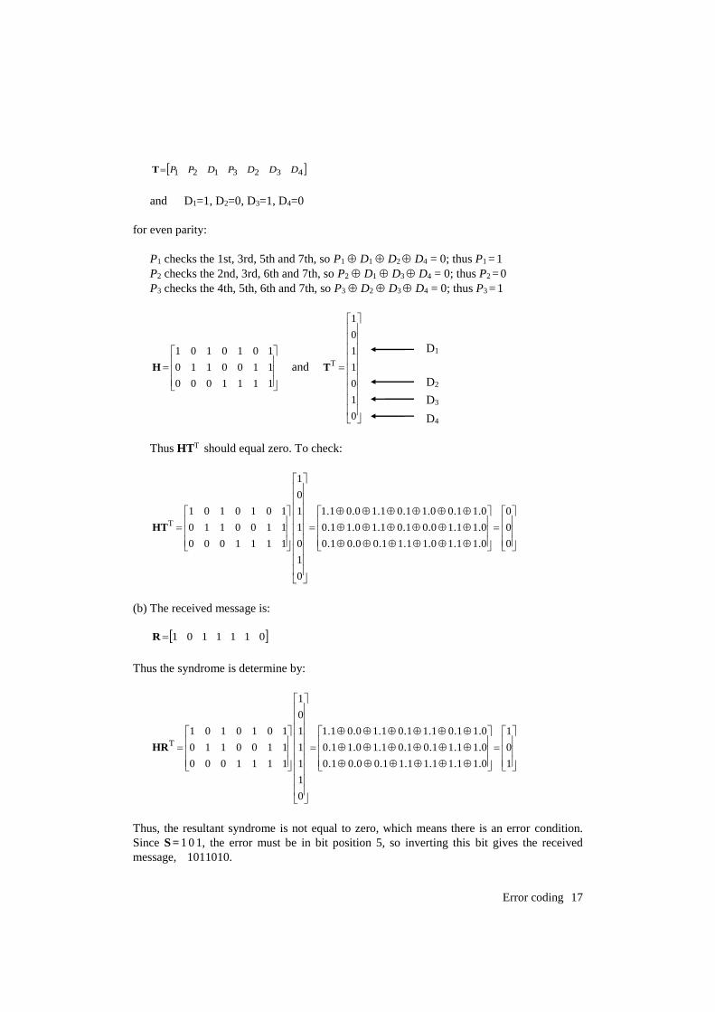
4323121 DDDPDPPT
and D1=1, D2=0, D3=1, D4=0
for even parity:
P1 checks the 1st, 3rd, 5th and 7th, so P1 D1 D2 D4 = 0; thus P1 = 1
P2 checks the 2nd, 3rd, 6th and 7th, so P2 D1 D3 D4 = 0; thus P2 = 0
P3 checks the 4th, 5th, 6th and 7th, so P3 D2 D3 D4 = 0; thus P3 = 1
1111000
1100110
1010101
H and
0
1
0
1
1
0
1
TT
Thus HTT should equal zero. To check:
0
0
0
0.11.10.11.11.00.01.0
0.11.10.01.01.10.11.0
0.11.00.11.01.10.01.1
0
1
0
1
1
0
1
1111000
1100110
1010101T
HT
(b) The received message is:
0111101R
Thus the syndrome is determine by:
1
0
1
0.11.11.11.11.00.01.0
0.11.11.01.01.10.11.0
0.11.01.11.01.10.01.1
0
1
1
1
1
0
1
1111000
1100110
1010101T
HR
Thus, the resultant syndrome is not equal to zero, which means there is an error condition.
Since S = 1 0 1, the error must be in bit position 5, so inverting this bit gives the received
message, 1011010.
D1
D2
D3
D4
18 Telecommunications
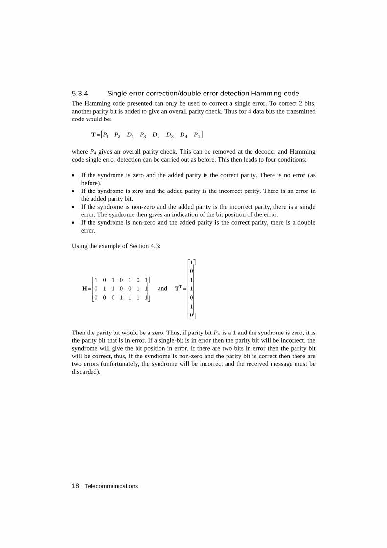
5.3.4 Single error correction/double error detection Hamming code
The Hamming code presented can only be used to correct a single error. To correct 2 bits,
another parity bit is added to give an overall parity check. Thus for 4 data bits the transmitted
code would be:
44323121 PDDDPDPPT
where P4 gives an overall parity check. This can be removed at the decoder and Hamming
code single error detection can be carried out as before. This then leads to four conditions:
If the syndrome is zero and the added parity is the correct parity. There is no error (as
before).
If the syndrome is zero and the added parity is the incorrect parity. There is an error in
the added parity bit.
If the syndrome is non-zero and the added parity is the incorrect parity, there is a single
error. The syndrome then gives an indication of the bit position of the error.
If the syndrome is non-zero and the added parity is the correct parity, there is a double
error.
Using the example of Section 4.3:
1111000
1100110
1010101
H and
0
1
0
1
1
0
1
TT
Then the parity bit would be a zero. Thus, if parity bit P4 is a 1 and the syndrome is zero, it is
the parity bit that is in error. If a single-bit is in error then the parity bit will be incorrect, the
syndrome will give the bit position in error. If there are two bits in error then the parity bit
will be correct, thus, if the syndrome is non-zero and the parity bit is correct then there are
two errors (unfortunately, the syndrome will be incorrect and the received message must be
discarded).