experimental investigation to optimise a desiccant hvac system coupled to a small size cogenerator
TRANSCRIPT

lable at ScienceDirect
Applied Thermal Engineering 31 (2011) 506e512
Contents lists avai
Applied Thermal Engineering
journal homepage: www.elsevier .com/locate/apthermeng
Experimental investigation to optimise a desiccant HVAC system coupledto a small size cogenerator
Giovanni Angrisani a,*, Francesco Minichiello b, Carlo Roselli a, Maurizio Sasso a
aDING, University of Sannio, Piazza Roma 21, 82100 Benevento, ItalybDETEC, University of Naples Federico II, P.le Tecchio 80, 80125 Naples, Italy
a r t i c l e i n f o
Article history:Received 9 February 2010Accepted 10 October 2010Available online 20 October 2010
Keywords:Decentralized polygenerationMicro-CCHPDesiccant wheelHybrid HVAC systemExperimental analysis
* Corresponding author. Tel.: þ39 0824 305576; faE-mail addresses: [email protected]
unina.it (F. Minichiello), [email protected] (C(M. Sasso).
1359-4311/$ e see front matter � 2010 Elsevier Ltd.doi:10.1016/j.applthermaleng.2010.10.006
a b s t r a c t
In the Mediterranean area, the increasing demand of summer cooling in residential and tertiary sectors isusually satisfied by electrically-driven units; this often determines electric load peaks and black-outs.Thus, a wide interest is spreading in small scale natural gas-fired polygeneration systems: a prime moverdrives (mechanically, electrically, thermally) electric generators and/or heat pumps, desiccant wheels,etc., matching thermal (heating and cooling) and electric end-user requirements.
In this paper, laboratory tests have been considered to experimentally evaluate a small scale poly-generation system based on a natural gas-fired Micro-CHP and a desiccant-based HVAC system.Cogenerated thermal power is used for the desiccant wheel regeneration, while electric power forauxiliaries, chiller and external units. The HVAC system can also interact with electric and thermalseparate “production” systems. The main results of the experimental tests are shown, stating the increaseof the COP of the chiller in desiccant-based HVAC systems. Then the paper identifies the operatingconditions (outdoor and supply air thermal-hygrometric conditions, electric grid efficiency and partialload operation of the MCHP) which guarantee significant primary energy savings (up to around 30%) andCO2 equivalent emission reductions (up to around 40%) of the polygeneration system compared to theconventional HVAC system.
� 2010 Elsevier Ltd. All rights reserved.
1. Introduction
During last years, great attention was focused on the transitionfrom centralized to decentralized energy “production” systems(Decentralized or Distributed Generation, DG), to reduce T&Denergy losses: aminiaturizationprocess (“size” effect) is inprogress.
A comparison between centralized and distributed powersystems is carried out in [1]: small, modern generators can be moreefficient and less costly to operate than large and old generators.This could lead to conclude that there is no longer an economy ofscale in power “generation”, but large modern power units havehigher electric efficiency and lower operating cost than smallmodern DG units based on the same technology. Since the “size”effect does not always lead to energy savings and pollutant emis-sion reductions, there is the need to support the diffusion of on-sitesmall complex energy conversion devices, Decentralized Poly-generation, DP. Awidespread use of DP systems could allow energy,
x: þ39 0824 325246.t (G. Angrisani), minichie@. Roselli), [email protected]
All rights reserved.
economic and environmental benefits: the benefits and drawbacksof DP are analysed in [2].
Furthermore, especially in Mediterranean area, there is anincreasing demand of summer cooling energy in domestic andtertiary sectors, usually satisfied by electrically-driven units; thisinvolves electric load peaks and black-outs. Thus, an increasinginterest occurs in small scale polygeneration systems fuelled bynatural gas.
Micro Combined Cooling, Heating and Power (MCCHP, electricpower output �15 kW) systems represent typical decentralizedenergy “production” systems, particularly suitable for use inMediterranean areas.
In the CCHP systems, the prime mover can be based on differenttechnologies (Stirling, Reciprocating Internal Combustion - RIC,Fuel Cell, Gas Turbine, etc.). The most mature technology availableon the market, gas-fired RIC engines, allows small installationspace, high thermal efficiency, low noise, vibrations and mainte-nance and long life service. These engines, coupled to electricgenerators, can drive electric heat pumps, thermal heat pumps,Desiccant Wheels - DW, etc., allowing a wide range of operatingconditions to match thermal (heating and cooling) and electricend-user requirements.
G. Angrisani et al. / Applied Thermal Engineering 31 (2011) 506e512 507
In summer, for dehumidification and/or cooling purposes,recovered thermal energy can be used for the regeneration of thedesiccant wheel, as well as for the activation of absorption/adsorption heat pumps, while, in winter, engine thermal wastesallow to satisfy domestic hot water and heating purposes. Thermalenergy input for desiccant wheel regeneration can also be derivedfrom solar source in Solar Heating and Cooling (SHC) systems[3e5]. Solar collectors are typically integratedwith fossil fuel-basedtechnologies to match the entire heat demand, SHC-CCHP systems.These systems offer the typical advantages of natural gas-firedpolygeneration systems coupled to a renewable energy source.Despite of these advantages, coupling solar collectors and a CCHPunit for heating, cooling and electric purposes presents certaincritical issues [6]; furthermore, this energy conversion system(solar thermal collectors, storage systems and CCHP) is verycomplex, both in design phase, to optimize the size of eachsubsystem, and during operation, its performance being dependenton many variables (energy tariff structure, load profiles, etc).
Few investigations have been carried out on solid desiccantsystems coupled to small scale combined cooling, heat and powersystems, and little attention has been paid on both energy andenvironmental performances [7e10].
Therefore, this paper experimentally analyses a desiccant-basedMCCHP system which includes a hybrid Air Handling Unit - AHU -(the term hybrid refers to the contemporary presence of a desiccantwheel and an electric chiller that, in succession, dehumidify andcool the air to be introduced in the conditioned space). This HVACsystem is suitable above all for residential and small commercialusers. An energy and environmental analysis for different operatingmodes has been carried out.
The system performance has been evaluated as a function ofvarious working conditions (outdoor and supply air thermal-hygrometric conditions and MCHP partial load operation), in orderto establish the effectiveness of such systems compared toa conventional HVAC system based on separate electric andthermal “production”. Finally, the influence of the electric gridefficiency to analyse the polygeneration system in different elec-tricity mix scenarios has been considered, as well as the effect ofthe regeneration temperature on the energy savings.
2. Test facility
At Sannio University, in Benevento (Southern Italy), a desiccantAir Handling Unit coupled to a cogenerator based on a natural gas-fired reciprocating internal combustion engine, an electric chillerand a natural gas-fired boiler, has been experimentally analysed.The hybrid HVAC system is based on dehumidification of outdoorair by a desiccant wheel and subsequent cooling by an electricchiller.
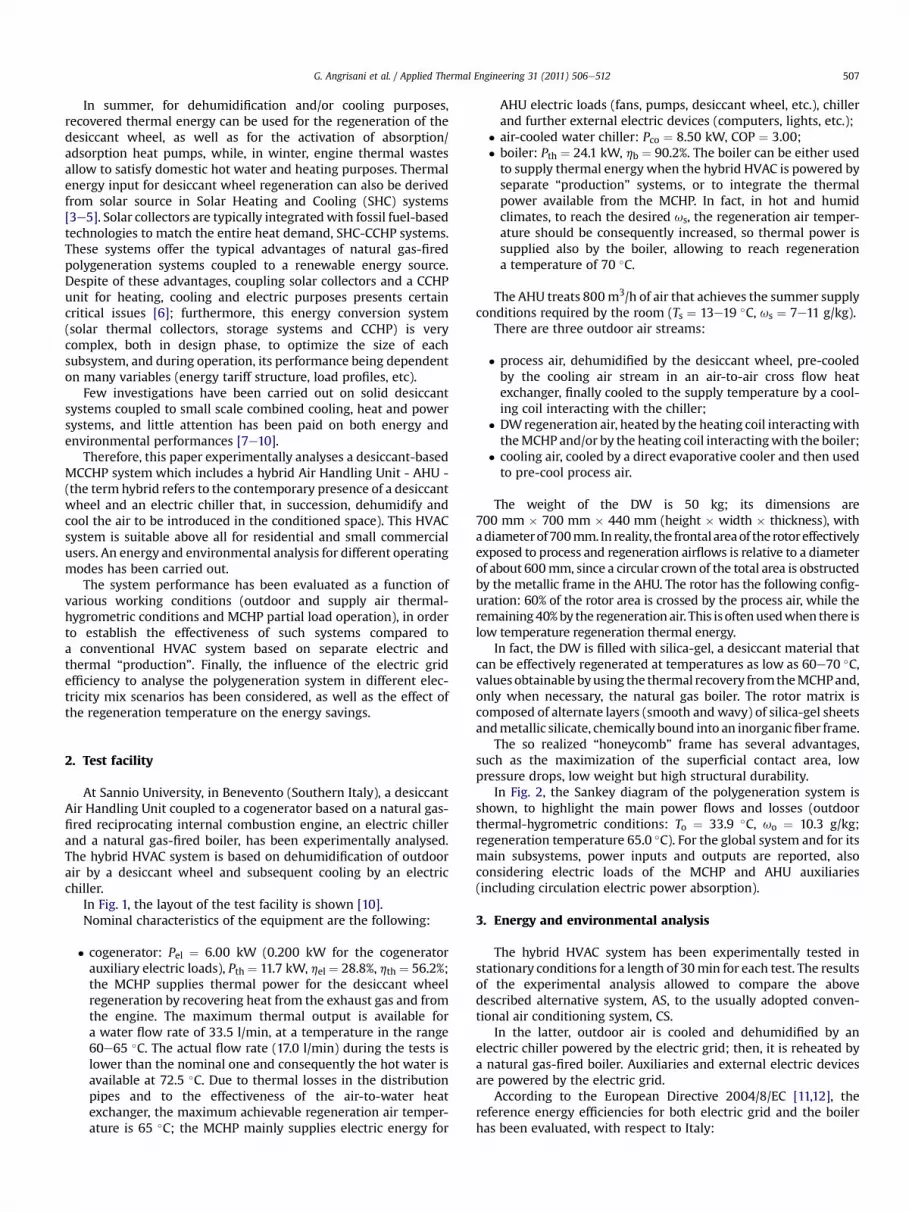
In Fig. 1, the layout of the test facility is shown [10].Nominal characteristics of the equipment are the following:
� cogenerator: Pel ¼ 6.00 kW (0.200 kW for the cogeneratorauxiliary electric loads), Pth ¼ 11.7 kW, hel ¼ 28.8%, hth ¼ 56.2%;the MCHP supplies thermal power for the desiccant wheelregeneration by recovering heat from the exhaust gas and fromthe engine. The maximum thermal output is available fora water flow rate of 33.5 l/min, at a temperature in the range60e65 �C. The actual flow rate (17.0 l/min) during the tests islower than the nominal one and consequently the hot water isavailable at 72.5 �C. Due to thermal losses in the distributionpipes and to the effectiveness of the air-to-water heatexchanger, the maximum achievable regeneration air temper-ature is 65 �C; the MCHP mainly supplies electric energy for
AHU electric loads (fans, pumps, desiccant wheel, etc.), chillerand further external electric devices (computers, lights, etc.);
� air-cooled water chiller: Pco ¼ 8.50 kW, COP ¼ 3.00;� boiler: Pth ¼ 24.1 kW, hb ¼ 90.2%. The boiler can be either usedto supply thermal energy when the hybrid HVAC is powered byseparate “production” systems, or to integrate the thermalpower available from the MCHP. In fact, in hot and humidclimates, to reach the desired us, the regeneration air temper-ature should be consequently increased, so thermal power issupplied also by the boiler, allowing to reach regenerationa temperature of 70 �C.
The AHU treats 800m3/h of air that achieves the summer supplyconditions required by the room (Ts ¼ 13e19 �C, us ¼ 7e11 g/kg).
There are three outdoor air streams:
� process air, dehumidified by the desiccant wheel, pre-cooledby the cooling air stream in an air-to-air cross flow heatexchanger, finally cooled to the supply temperature by a cool-ing coil interacting with the chiller;
� DWregeneration air, heated by the heating coil interactingwiththeMCHP and/or by the heating coil interactingwith the boiler;
� cooling air, cooled by a direct evaporative cooler and then usedto pre-cool process air.
The weight of the DW is 50 kg; its dimensions are700 mm � 700 mm � 440 mm (height � width � thickness), withadiameterof700mm. In reality, the frontal areaof the rotoreffectivelyexposed to process and regeneration airflows is relative to a diameterof about 600mm, since a circular crown of the total area is obstructedby the metallic frame in the AHU. The rotor has the following config-uration: 60% of the rotor area is crossed by the process air, while theremaining40%by the regeneration air. This is oftenusedwhen there islow temperature regeneration thermal energy.
In fact, the DW is filled with silica-gel, a desiccant material thatcan be effectively regenerated at temperatures as low as 60e70 �C,values obtainable byusing the thermal recovery fromtheMCHPand,only when necessary, the natural gas boiler. The rotor matrix iscomposed of alternate layers (smooth and wavy) of silica-gel sheetsandmetallic silicate, chemically bound into an inorganicfiber frame.
The so realized “honeycomb” frame has several advantages,such as the maximization of the superficial contact area, lowpressure drops, low weight but high structural durability.
In Fig. 2, the Sankey diagram of the polygeneration system isshown, to highlight the main power flows and losses (outdoorthermal-hygrometric conditions: To ¼ 33.9 �C, uo ¼ 10.3 g/kg;regeneration temperature 65.0 �C). For the global system and for itsmain subsystems, power inputs and outputs are reported, alsoconsidering electric loads of the MCHP and AHU auxiliaries(including circulation electric power absorption).
3. Energy and environmental analysis
The hybrid HVAC system has been experimentally tested instationary conditions for a length of 30min for each test. The resultsof the experimental analysis allowed to compare the abovedescribed alternative system, AS, to the usually adopted conven-tional air conditioning system, CS.
In the latter, outdoor air is cooled and dehumidified by anelectric chiller powered by the electric grid; then, it is reheated bya natural gas-fired boiler. Auxiliaries and external electric devicesare powered by the electric grid.
According to the European Directive 2004/8/EC [11,12], thereference energy efficiencies for both electric grid and the boilerhas been evaluated, with respect to Italy:

Fig.
1.Layo
utof
thetest
facility.
G. Angrisani et al. / Applied Thermal Engineering 31 (2011) 506e512508

CHILLER
MCHP
( )thelelASp η-η-1ηE
ASpE
DW
thASp ηE
elASp ηE ( ) US
eleelASp Er-1ηE
eelASp rηE
UScoE
AHU
COOLING COIL
ASeel
ASp COPrηE
thASpE
HEATING COIL
process section
regeneration section
Process air
Regeneration air
USelE
UScoE
USERALTERNATIVE SYSTEM CONVENTIONAL SYSTEM
HEATING COIL
CHILLER ELECTRIC
GRID
COOLINGCOIL
BOILER
AHU
CHelE
BthE
EGpE
BpE
CSpE
USelE
CSCHel COPE
Process air
UScoE
Fig. 3. Energy flows of alternative system and conventional system.
Fig. 2. Sankey diagram of the polygeneration system.
G. Angrisani et al. / Applied Thermal Engineering 31 (2011) 506e512 509
� Electric grid: heg ¼ 45.2%, CO2 equivalent emission ¼0.531 kgCO2/kWhel [13];
� Boiler: efficiency¼ 90%, CO2 equivalent emission¼ 0.20 kgCO2/kWhp; natural gas lower heating value ¼ 9.59 kWh/Nm3.
The comparison is carried out assuming that both AS and CSdeliver equal energy (electric and cooling energy; thermal energyrecovered from the MCHP is fully used to DW regeneration).Moreover, the two systems handle 800 m3/h of process air andoperate at the same outdoor and supply thermal-hygrometricconditions. For example, Fig. 3 shows the energy flows of AS and CS.
The Primary Energy Saving, PES, has been considered for theenergy comparison [14]:
PES ¼ ECSp � EASpECSp
(1)
Furthermore, the avoided CO2 equivalent emissions of the alter-native system with respect to the conventional one have beenevaluated too.
4. Experimental analysis
The start-up of the experimental test facility (calibration of themeasuring systems, design of data acquisition and monitoringsoftware, etc.) has been initially carried out. A user-friendlygraphical interface records the most significant parameters, suchas: air temperature and relative humidity in themain AHU sections,inlet and outlet water temperature for heat exchangers, boiler,MCHP and chiller, volumetric flow rate (water and natural gas),electric energy and power flows. So, thermal and electrical MCHPefficiencies, COP of the chiller, PER, etc., have been evaluated too.
After a starting phase [10], during summer 2009, many testshave been carried out, representing a wide range of outdoor airthermal-hygrometric conditions and different AHU operatingmodes.
AHUs based on chemical dehumidification have the advantageof reducing cooling energy demand, for the lack of cooling-baseddehumidification, on which the conventional air conditioningsystems are instead based. Furthermore, the refrigeration unit can

2.5
3.0
3.5
1.0
1.5
2.0
23 25 27 29 31 33 35
]-[P
OC
Outdoor air temperature [°C]
DW 4.86 g/kg5.86 g/kg 6.86 g/kg7.86 g/kg 8.86 g/kg9.88 g/kg 10.8 g/kg
Fig. 4. COP of the electric chiller in the conventional HVAC system (for different valuesof supply air humidity ratio) and in the desiccant-based HVAC system, as a function ofthe outdoor air temperature.
10
20
30
40
25.0 °C
29.0 °C
33.5 °C
-30
-20
-10
0
8 9 10 11 12 13 14 15 16
]%[
SE
P
Outdoor air humidity ratio [g/kg]
Fig. 6. PES as a function of outdoor air humidity ratio for three different values ofoutdoor air temperature.
G. Angrisani et al. / Applied Thermal Engineering 31 (2011) 506e512510
produce chilledwater at higher temperatures, compared to a chillerthat operates in a conventional HVAC system, and consequently itwill operate with higher COP.
For these reasons, attention has been paid to the evaluation ofthe performance of the electric chiller in the CS: a detailed model,based on well known simulation codes of inverse machines, allowsto evaluate the performance of the air-cooled water chiller [15,16].Both full and part load operating conditions have been considered,in agreement with [17].
Many tests have been realized, considering different operatingconditions and electric energy quantities supplied to the final user.
In Fig. 4, the full load COP of the chiller in alternative andconventional HVAC systems is reported as a function of To and fordifferent us values. The COP in the alternative system (“DW”)obviously does not depend on us because the dehumidification iscarried out by the desiccant wheel, not by the chiller. Contrariwise,the COP of the chiller interacting with the cooling/dehumidificationcoil strongly decreases on us reduction. For many operatingconditions, the chiller interacting with the hybrid HVAC system
Fig. 5. Psychrometric chart showing the area w
performs better than the conventional one that has also a “size”(cooling capacity) more than twice. Only for low outdoor temper-ature (<29 �C) and high values of supply air humidity ratio(�10.8 g/kg) COP of the chiller interacting with the conventionalAHU is greater than the alternative one.
To highlight the influence of outdoor air properties on theenergy performances of AS and CS, in Fig. 5 outdoor air thermal-hygrometric conditions that get a positive PES are shown. Thehybrid HVAC system interacting with the MCHP requires lessprimary energy than the conventional system for uo lower thanabout 11.5 g/kg and To in the range 25e36 �C. For uo > 11.5 g/kg, thelower limit of the previous temperature range increases: foruo ¼ 13.0 g/kg, AS is preferable only for To > 28 �C. Finally, foruo > 13.0 g/kg, AS is no more energetically suitable.
In Fig. 6, the PES as a function of uo and for three different valuesof To is shown. PES increases when uo decreases, reachinga maximum value for uo ¼ 8.00 g/kg (24%, 31% and 35% for To equalto 25.0 �C, 29.0 �C and 33.5 �C, respectively). PES becomes positivewhen uo is lower than a certain value, depending on outdoor airtemperature (11.4 g/kg, 12.6 g/kg and 13.0 g/kg for the three Tovalues, respectively). Moreover, PES increases with To.
here PES is <0 and that where PES is >0.

Table 1Operating conditions for the test of Fig. 7.
Outdoor air temperature [�C] Outdoor air humidity ratio [g/kg] Supply air temperature [�C] Supply air humidity ratio [g/kg] Regeneration temperature [�C]
33.9 10.3 20.1 6.50 65.0
-10
0
10
20
30
0.0 0.3 0.6 0.9 1.2 1.5
PES
[%]
Net electric power to final user [kW]
Fig. 8. PES as a function of net electric power supplied to the final user.
G. Angrisani et al. / Applied Thermal Engineering 31 (2011) 506e512 511
In the range of operating conditions of Fig. 6, the avoided CO2equivalent emissions show the same trend as PES, achievingamaximumvalue of 43%. The avoided emissions go to zerowhenuois in the range 14.5e16 g/kg (depending on To value), while PES goesto zero when uo is in the range 11.4e13.0 g/kg. Therefore, theambient convenience remains in a wider outdoor humidity ratiorange compared to the energy convenience.
As explained above, the electric grid efficiency remains a keyfactor. In Fig. 7, at constant operating conditions (Table 1), theinfluence of heg on PES is reported. In the base case (heg ¼ 45.2%),PES is about 22%; then it increases with heg reduction.
The influence of the partial load operation of the MCHP on theglobal energy performance has been analysed too. The net electricpower for computers, lights, etc., has been gradually increased up to1.5 kW to allow the full load of the cogenerator (for To¼ 29.5 �C anduo ¼ 10.2 g/kg, the electric power supplied by the MCHP to thechiller and to the MCHP and AHU auxiliaries is about 4.5 kW). Fig. 8shows that PES increases with the net electric power supplied tothe final user, so it is convenient to operate theMCHP at full load forthe maximum number of hours (PES of around 24%): this, in fact,causes an increase of electric efficiency of the micro-cogenerator.Also in this case, the reduction of CO2 equivalent emissions showsthe same trend as PES; it achieves the maximum value (35%) at fullload operation of the MCHP.
In a previous paper, the influence of the regeneration temper-ature on the selected DW performance has been analysed [18]. Ithas been shown that the dehumidification capability of the wheel,Δu, increases when regeneration temperature rises: withTo ¼ 30.5 �C and uo ¼ 10.7 g/kg, Δu varies from 1.0 g/kg to 5.6 g/kgwhen regeneration temperature increases from 34 to 72 �C.
It is evident that the reduction of process air humidity ratio thatthe DW realizes, Δu, is strictly related to the room latent load it hasto balance. Therefore, the regeneration temperature can be used asa control parameter, in desiccant-based HVAC systems, to dynam-ically follow the latent load to handle. If, for example, the latterdecreases, the regeneration temperature can be automaticallyreduced.
If the MCHP continues working at full load, as this is the bestoperating condition in terms of energy performance (see Fig. 8), thereduction of the regeneration temperature can be achieved, atconstant regeneration air flow rate (800 m3/h), only by wastinga part of the available thermal power. Therefore, the PES obviously
0
10
20
30
40
0.36 0.40 0.44 0.48 0.52 0.56 0.60
PES
[%]
Electric grid efficiency [-]
Fig. 7. PES as a function of electric grid efficiency.
reduces. In fact, in the same outdoor operating conditions as above(To ¼ 30.5 �C and uo ¼ 10.7 g/kg), it decreases from 30% to �10%when the regeneration temperature reduces from 65 to 34 �C.
The desiccant-based HVAC system can also be powered byseparate “production” of electric and thermal energy, respectivelyprovided by the electric grid and a natural gas boiler. Consideringthe above reported values for the boiler (90%) and the electric gridefficiency (45.2%), the desiccant-based HVAC system powered bytheMCHP (AS) guarantees an average PES of 18%with respect to thesame system powered by separate “production”. Even if the electricenergy “production” is based on the Best Available Technology(BAT, i.e. with natural gas combined cycle power plants, heg ¼ 0.58),PES remains positive (8.2% on average).
The PES values obtained in this work are in good agreementwith quite similar polygeneration systems and operating condi-tions [7,8].
5. Conclusions
Experimental tests have been carried out in Benevento(Southern Italy) to analyse a hybrid desiccant HVAC system drivenby a MCCHP, in order to evaluate its energy and environmentalperformances compared to a conventional system based on anelectric chiller.
The performances of the two systems are strongly influenced byoutdoor thermal-hygrometric conditions: the alternative systemcan guarantee a Primary Energy Saving when outdoor air humidityratio is lower than a certain value (11.5 g/kg) and outdoor airtemperature is in the range 25e36 �C. Moreover, PES increases withTo and when uo decreases, reaching a maximum value foruo ¼ 8.0 g/kg, 24% for To ¼ 25.0 �C, 31% for To ¼ 29.0 �C, 35% forTo ¼ 33.5 �C. The avoided CO2 equivalent emissions show the sametrend as PES, achieving a maximum value of 43%.
Obviously, PES decreases when electric grid efficiency increases.Moreover, the best performance (PES of around 24%, considering
the operating conditions of the specific test) is obtained when theMCHP works at full load; so a detailed analysis of the electric loadsand a correct sizing of the small-scale cogeneration system have tobe carried out to minimize the operating hours at partial load. Alsoin this case, the reduction of CO2 equivalent emissions show thesame trend as PES; it achieves the maximumvalue (35%) at full loadoperation of the MCHP.

G. Angrisani et al. / Applied Thermal Engineering 31 (2011) 506e512512
With the MCHP working at full load, if the regenerationtemperature has to be automatically decreased for control purposes(to reduce the latent load balanced by the desiccant wheel), the PESdecreases until it becomes negative for very low regenerationtemperatures (minus than 42 �C).
Furthermore, the desiccant-based HVAC system powered by theMCHP (AS) guarantees an average PES of 18% with respect to thesame HVAC system powered by separate “production” of electricand thermal energy. Even if the electric energy “production” isbased on the Best Available Technology (BAT, heg ¼ 0.58), PESremains positive (8.2% on average).
Further investigations are required as regards economic savingsand the introduction of a solar collecting system in the existingpolygeneration plant.
Acknowledgements
This work has been financed by Italian research projectPRIN 2007 “Criteria and methodologies for the optimization ofsmall/medium scale polygeneration systems”.
Moreover, this work was developed in a research projectpromoted by International Energy Agency (IEA), Annex 54, Inte-gration of Micro-generation and Related Energy Technologies inBuildings.
Nomenclature
CO2 carbon dioxide equivalent emissions [kg/h]E energy [kJ]P power [kW]PES primary energy saving [�]re electric energy share provided to the chiller [�]RH relative humidity [%]T temperature [�C]h efficiency [�]u air humidity ratio [g/kg]Δu air humidity ratio variation [g/kg]AHU air handling unitAS alternative systemBAT best available technologyCCHP combined cooling heating and powerCHP combined heat and powerCOP coefficient of performanceCS conventional systemDG decentralized or distributed generationDP decentralized or distributed polygenerationDW desiccant wheelHVAC heating, ventilation and air conditioningMCCHP micro combined cooling heat and powerMCHP micro combined heat and powerRIC reciprocating internal combustionSHC solar heating and coolingT&D transmission and distribution
SubscriptsAHU air handling unitb boilerco coolingo outdoor aireg electric grid
el electricp primarys supply airth thermal
SuperscriptsAS alternative systemB boilerCS conventional systemCH chillerEG electric gridUS end user
References
[1] H.L. Willis, W.G. Scott, Distributed Power Generation: Planning and Evalua-tion. Marcel Dekker Inc., New York, 2000, ISBN 0-8247-0336-7.
[2] R. Possidente, C. Roselli, M. Sasso, S. Sibilio, Small scale decentralized poly-generation systems, Proceedings of ECOS 2009, 22nd International Conferenceon Efficiency, Cost, Optimization, Simulation and Environmental Impact ofEnergy Systems, Foz do Iguaçu, Paraná, Brazil, August 31eSeptember 3, 2009.
[3] D. Pietruschka, U. Eicker, V. Nanby, Primary energy optimised operation ofsolar driven desiccant evaporative cooling systems through innovative controlstrategies, Proceedings of 3rd Solar Air Conditioning International Conference,Palermo, Italy, September 31eOctober 2, 2009-12-29.
[4] Y.J. Dai, D. La, Y. Li, Z.X. Jiang, T.S. Ge, R.Z. Wang, An energy efficient solardriven two-stage rotary desiccant cooling system: experiment and case study,Proceedings of 3rd Solar Air Conditioning International Conference, Palermo,Italy, September 31eOctober 2, 2009-12-29.
[5] M. Beccali, P. Finocchiaro, B. Nocke, Solar desiccant cooling system operatingin Palermo (Itay): results and validation of simulation results, Proceedings of3rd Solar Air Conditioning International Conference, Palermo, Italy, September31 e October 2, 2009-12-29.
[6] A. Napolitano, G. Franchini, G. Nurzia, W. Sparber, Coupling solar collectorsand co-generation units in solar assisted heating and cooling systems,Proceedings of EUROSUN 2008, 1st International Conference on Heating,Cooling and Buildings, Lisbon, Portugal, October 7-10, 2008.
[7] G. Schmitz, W. Casas, Experiences with a small gas engine driven desiccantHVAC-system, Proceedings of IGRC 2001, 8th International Gas ResearchConference, Amsterdam, The Netherlands, November 5-8, 2001.
[8] G. Schmitz, W. Casas, Experiences with a gas driven, desiccant assisted airconditioning system with geothermal energy for an office building, Energyand Buildings 37 (5) (2005) 493e501.
[9] A. Jalalzadeh-Azar Ali, S. Slayzak, R. Judkoff, Performance assessment ofa desiccant cooling system in a CHP application incorporating an IC engine,International Journal of Distributed Energy Resources 1 (2) (2005) 163e184.
[10] G. Angrisani, F. Minichiello, C. Roselli, M. Sasso, G.P. Vanoli, Experimentalanalysis of small scale polygeneration system based on a natural gas-firedMicro-CHP and a hybrid HVAC system equipped with a desiccant wheel,Proceedings of ECOS 2009, 22nd International Conference on Efficiency, Cost,Optimization, Simulation and Environmental Impact of Energy Systems, Fozdo Iguaçu, Paraná, Brazil, August 31eSeptember 3, 2009.
[11] Directive 2004/8/EC of the European Parliament and the Council of 11February on the promotion of cogeneration based on a useful heat demand inthe internal energy market and amending Directive 92/42/EEC, Official Journalof the European Union (21.02.2004).
[12] Commission Decision of 21st December 2006, Establishing harmonised effi-ciency reference values for separate production of electricity and heat inapplication of Directive 2004/8/EC of the European Parliament and of theCouncil, Official Journal of the European Union (06.02.2007).
[13] Italian Environmental Ministry.www.minambiente.it.[14] V. Dorer, A. Weber, Methodologies for the performance assessment of resi-
dential cogeneration systems, vol. 42, Report of IEA ECBCS Annex, 2007.[15] CoolPack Version 1.46 Copyright � Department of Mechanical Engineering,
Technical University of Denmark.www.et.dtu.dk/CoolPack (2000).[16] IMST-ART Version 3.20.02 Instituto de Ingeniería Energética Universidad
Politécnica de Valencia.www.imst-art.com.[17] E. Bettanini, A. Gastaldello, L. Schibuola, Simplified models to simulate part
load performances of air conditioning equipments, Proceedings of IBPSA 2003,8th International Conference of International Building Performance Simula-tion Association, Eindhoven, The Netherlands, August 11-14, 2003.
[18] G. Angrisani, F. Minichiello, C. Roselli, M. Sasso, Desiccant HVAC system drivenby a micro-CHP: experimental analysis, Energy and Buildings 42 (11) (2010)2028e2035.