experimental investigation of a novel desiccant cooling system
TRANSCRIPT
E
Ea
b
c
a
ARA
KADDAE
1
bstimcc(Rocr
iTcsbsaabc
0d
Energy and Buildings 42 (2010) 2049–2060
Contents lists available at ScienceDirect
Energy and Buildings
journa l homepage: www.e lsev ier .com/ locate /enbui ld
xperimental investigation of a novel desiccant cooling system
rtac Hürdogana,∗, Orhan Büyükalacab, Tuncay Yılmaza, Arif Hepbaslı c
Department of Mechanical Engineering, Faculty of Engineering and Architecture, Cukurova University, 01330 Balcalı, Adana, TurkeyDepartment of Energy Systems Engineering, Faculty of Engineering, Osmaniye Korkut Ata University, 80000 Osmaniye, TurkeyDepartment of Mechanical Engineering, Faculty of Engineering, Ege University, 35100 Bornova, Izmir, Turkey
r t i c l e i n f o
rticle history:eceived 30 March 2010
a b s t r a c t
Desiccant based air conditioning systems are a suitable way to improve indoor air quality due to itssuperior humidity control. In this study, a novel desiccant based air conditioning system is designed and
ccepted 21 June 2010
eywords:ir conditioningehumidificationesiccant wheelir quality
tested experimentally to improve the indoor air quality and reduce energy consumption. In the systemstudied, a heat exchanger, which is not used in this type of systems, for pre-heating the regeneration airwith exhaust air is used. This paper reports results of initial operation and operational procedures. Theperformance of the system and its components is discussed.
© 2010 Elsevier B.V. All rights reserved.
xperiment
. Introduction
Relative humidity at the indoor environment of buildings muste within a specified range for human comfort [1]. Since infectionspread through air depend on humidity in some medical institu-ions like hospitals, humidity control in air conditioning is verymportant [2]. In conventional systems commonly used for sum-
er air conditioning, the air sent to the place being air-conditionedomes through coils, cooled by a cooling unit generally by a vaporompressing cycle. While coming through coils, both the heatsensible heat) and the humidity (latent heat) of air are reduced.emoving humidity from the air is realized by the condensationf the water steam in the air, which meets cold coil. This pro-ess creates a suitable atmosphere in the air sent to the place, foreproduction of bacteria that can cause infections [3].
Desiccant based air conditioning systems are a suitable way tomprove indoor air quality due to its superior humidity control.hese systems are also alternatives for air conditioning in healthare facilities to reduce the airborne disease transmission. The sub-tances used in these processes for removing moisture, remove theacteria that can cause illnesses and various infections in the airent to the place being air-conditioned [4–8]. In desiccant based
ir conditioning systems, a desiccant removes moisture from their, which releases heat and increases the air temperature. A com-ination of heat exchange with ambient air and evaporative oronventional cooling coils then cools the dry air. Temperature and∗ Corresponding author. Tel.: +90 322 338 6084x2722; fax: +90 322 338 6126.E-mail address: [email protected] (E. Hürdogan).
378-7788/$ – see front matter © 2010 Elsevier B.V. All rights reserved.oi:10.1016/j.enbuild.2010.06.014
humidity loads are very effectively and efficiently met by separat-ing them in this way. The desiccant is then dried out (regenerated)to complete the cycle using thermal energy.
Several review studies are performed on the description andoperation of desiccant cooling systems by different researchers[9–12]. Systems that use rotary desiccant wheel to dehumidify theair are the most popular desiccant cooling systems and studied bydifferent researchers [13–15]. They showed that desiccant coolingsystems are viable alternative to vapor compression systems. Mostsolid desiccant cooling systems operate according to the Penning-ton cycle [16] also known as ventilation cycle. In this cycle, ambientair is taken into a rotating desiccant dehumidifier where moistureis adsorbed. The air is then sensibly and evaporatively cooled andintroduced into the air-conditioned room. The air exiting room isfirst evaporatively cooled, then passed through the sensible heatexchanger where it recovers heat of adsorption from the supplyair. Next, it is heated with low-grade thermal energy and the hotair is used to regenerate the desiccant.
In addition to the rotary desiccant cooling systems that operateaccording to the Pennington cycle, some different arrangements(cycles) were also studied in the literature. One early variationof the Pennington cycle was the recirculation cycle. In this cycle,return air is used as process air and ambient air is used as regener-ation air. The main disadvantage of recirculation cycle is lacking infresh air. Dunkle cycle [17], which in a sense is a cross between the
Pennington and recirculation cycles, has an additional sensible heatexchanger for improving the cycle performance. Maclaine-Cross[18] proposed a simplified advanced solid desiccant cycle, namelySENS cycle. In this cycle, ambient air is first dehumidified in a rotarydesiccant wheel, and then sensibly cooled in two heat exchanger in
2050 E. Hürdogan et al. / Energy and Bui
Nomenclature
cp Specific heat (kJ/kg K)C Capacitance rate (kW/K)COP Coefficient of performanceEtot Total energy input (kW)h Enthalpy (kJ/kg)m Mass flow rate (kg/s)Q Actual heat transfer rate (kW)QCC Cooling capacity (kW)Qmax Maximum possible heat transfer rate (kW)Qreg Energy consumption of regeneration heat (kW)T Temperature (◦C)W Humidity ratio (kg/kg air)W Power consumption (kW)�W Moisture removal (kg/kg air)
Greek letter� Effectiveness
Subscripts1, 2, ..., 17 States described in Fig. 1c Cold aircom CompressorEC Evaporative coolereh Electric heatersfan Fansf Fresh airh Hot airHE Heat exchangeri Inletmin Minimumo Outlet
tbcictficvwc
ipaiewtcirfissdst
oth Other electrical componentsw Wet bulb
andem. It is then mixed with return air and cooled in a cooling coily exchanging heat with cold water from a cooling tower. Someooled air from the coil is supplied to the cooling tower from whicht is discharged to the atmosphere and the rest is supplied to theonditioned space. On the regeneration side, ambient air is passedhrough the heat exchanger. Then, it is heated by heat source andnally drawn through the desiccant wheel to regenerate the desic-ant. Jain et al. [19] investigated various solid desiccant cycles (theentilation cycle, the recirculation cycle, the Dunkle cycle and theet surface heat exchangers cycle (SENS cycle)) for various outdoor
onditions of many cities in India.Various researchers studied a system that regenerates the des-
ccant with double stage (staged regeneration) to improve thermalerformance of rotary desiccant air conditioning systems. Ando etl. [20] investigated experimentally a four-rotor desiccant cool-ng process equipped with a double stage dehumidification. Theirxperimental results showed that the amount of dehumidifiedater at the process without evaporative cooler was larger than
hat of process with evaporative cooler. Performance of a desiccantooling system with double stage dehumidification was also stud-ed by Zhang and Niu [21] and Ge et al. [22]. They reported that theequired regeneration temperature of the system is lower and coef-cient of performance is higher than single stage desiccant cooling
ystem. Ge et al. [23] investigated experimentally a one-rotor twotage rotary desiccant cooling system (OTSDC), in which two stageehumidification process is realized by one desiccant wheel. Theyhowed that OTSDC achieved the objective of reducing the size ofwo stage system with no reduction in system performance.ldings 42 (2010) 2049–2060
In addition to these cycles, some hybrid desiccant air condi-tioning systems are also studied. Tsay et al. [24] investigated thepossibilities and methods of combining a desiccant cooling systemwith a CO2 heat pump to improve overall efficiency and indoorair quality and to provide a steady heat source. They showed thatusing a relatively low reactivation temperature could satisfy thenon-condensing premise and provide good indoor air quality con-ditions without mold pollution. It was also found that Coefficientof Performance (COP) of system based on energy consumption canbe improved from 0.6 to 1.8.
Desiccant cooling systems are cost effective systems when acheap heat source especially solar energy is used to regeneratethe desiccant. For this purpose, various studies were performed[25–30].
The literature search showed that different types of rotarydesiccant cooling systems were studied both analytically andexperimentally by several researchers. In this study, a novel des-iccant based air conditioning system was designed and testedexperimentally to improve the indoor air quality and reduce energyconsumption. In the system studied, the moisture of the air sentto the place being air-conditioned was reduced passing it througha solid desiccant wheel and then its temperature was brought tothe desired blowing temperature by the “dry coil” of a vapor com-pression cycle. To enhance the performance of the system, sometechniques such as “pre-cooling with outdoor air”, “waste coolrecovery”, “pre-cooling of waste air with evaporative cooling” and“pre-heating the regeneration air with exhaust air” were utilized.
2. System description and experimental setup
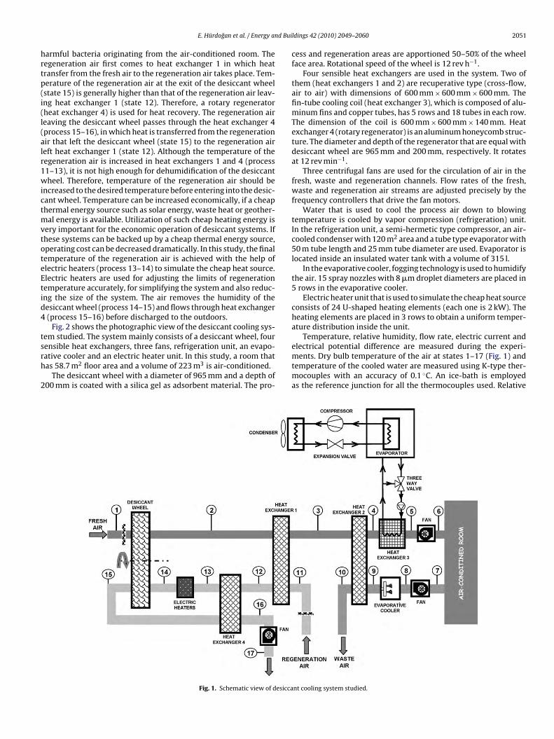
Fig. 1 illustrates a schematic view of desiccant cooling systemstudied. In the system, three separate air channels are used for fresh,waste and regeneration air streams. Fresh air channel is used to sup-ply fresh air to the air-conditioned room. The waste air sucked fromthe air-conditioned room is sent to outside via waste air channel.Regeneration air channel is used to remove moisture of desiccantwheel.
Humidity of the fresh outside air (state 1) is absorbed by thedesiccant material of the wheel. The fresh air leaves the processside of the desiccant wheel (state 2) hotter, and much drier thanwhen entering the system. Sensible cooling of the fresh air is carriedout (process 4–5) in a cooling coil, which is fed by chilled waterfrom a chiller unit. However, the fresh air is passed through tworecuperative type heat exchangers (heat exchangers 1 and 2) beforecoming to the cooling coil for cool recovery. In the recuperators,only sensible heat is removed from the fresh air, and therefore,humidity ratio of the air remains constant.
The desired blowing temperature of the fresh air (state 6) isobtained in the cooling coil. The surface temperature of the cool-ing coil is always kept higher than the dew point temperature ofthe fresh air entering into the cooling coil. Therefore, only sensi-ble cooling is performed in the coil (dry coil application). Moisturefrom the fresh air (latent cooling) is removed only in the desiccantwheel and there is no change in the humidity ratio of the fresh airafter the desiccant wheel.
The air sucked from the indoor (state 7) into the waste air duct isevaporatively cooled before entering into heat exchanger 2 in orderto increase the cool recovery. In heat exchanger 2, due to the heattransfer from the fresh air to the waste air, temperature of the freshair decreases and that of the waste air increases (process 9–10). The
waste air leaving the heat exchanger is rejected to the outdoors.Hot regeneration air is used for removing moisture at the desic-cant wheel. In this study, fresh outdoor air is used for regenerationprocess. The reason of using ambient air is to eliminate the possibil-ity of mixing of the fresh air with the waste air, which may contain
d Bui
hrtp(i(l(alr1wictmvtoteEtid4
tsrh
2
E. Hürdogan et al. / Energy an
armful bacteria originating from the air-conditioned room. Theegeneration air first comes to heat exchanger 1 in which heatransfer from the fresh air to the regeneration air takes place. Tem-erature of the regeneration air at the exit of the desiccant wheelstate 15) is generally higher than that of the regeneration air leav-ng heat exchanger 1 (state 12). Therefore, a rotary regeneratorheat exchanger 4) is used for heat recovery. The regeneration aireaving the desiccant wheel passes through the heat exchanger 4process 15–16), in which heat is transferred from the regenerationir that left the desiccant wheel (state 15) to the regeneration aireft heat exchanger 1 (state 12). Although the temperature of theegeneration air is increased in heat exchangers 1 and 4 (process1–13), it is not high enough for dehumidification of the desiccantheel. Therefore, temperature of the regeneration air should be
ncreased to the desired temperature before entering into the desic-ant wheel. Temperature can be increased economically, if a cheaphermal energy source such as solar energy, waste heat or geother-
al energy is available. Utilization of such cheap heating energy isery important for the economic operation of desiccant systems. Ifhese systems can be backed up by a cheap thermal energy source,perating cost can be decreased dramatically. In this study, the finalemperature of the regeneration air is achieved with the help oflectric heaters (process 13–14) to simulate the cheap heat source.lectric heaters are used for adjusting the limits of regenerationemperature accurately, for simplifying the system and also reduc-ng the size of the system. The air removes the humidity of theesiccant wheel (process 14–15) and flows through heat exchanger(process 15–16) before discharged to the outdoors.
Fig. 2 shows the photographic view of the desiccant cooling sys-em studied. The system mainly consists of a desiccant wheel, four
ensible heat exchangers, three fans, refrigeration unit, an evapo-ative cooler and an electric heater unit. In this study, a room thatas 58.7 m2 floor area and a volume of 223 m3 is air-conditioned.The desiccant wheel with a diameter of 965 mm and a depth of00 mm is coated with a silica gel as adsorbent material. The pro-
Fig. 1. Schematic view of desicca
ldings 42 (2010) 2049–2060 2051
cess and regeneration areas are apportioned 50–50% of the wheelface area. Rotational speed of the wheel is 12 rev h−1.
Four sensible heat exchangers are used in the system. Two ofthem (heat exchangers 1 and 2) are recuperative type (cross-flow,air to air) with dimensions of 600 mm × 600 mm × 600 mm. Thefin-tube cooling coil (heat exchanger 3), which is composed of alu-minum fins and copper tubes, has 5 rows and 18 tubes in each row.The dimension of the coil is 600 mm × 600 mm × 140 mm. Heatexchanger 4 (rotary regenerator) is an aluminum honeycomb struc-ture. The diameter and depth of the regenerator that are equal withdesiccant wheel are 965 mm and 200 mm, respectively. It rotatesat 12 rev min−1.
Three centrifugal fans are used for the circulation of air in thefresh, waste and regeneration channels. Flow rates of the fresh,waste and regeneration air streams are adjusted precisely by thefrequency controllers that drive the fan motors.
Water that is used to cool the process air down to blowingtemperature is cooled by vapor compression (refrigeration) unit.In the refrigeration unit, a semi-hermetic type compressor, an air-cooled condenser with 120 m2 area and a tube type evaporator with50 m tube length and 25 mm tube diameter are used. Evaporator islocated inside an insulated water tank with a volume of 315 l.
In the evaporative cooler, fogging technology is used to humidifythe air. 15 spray nozzles with 8 �m droplet diameters are placed in5 rows in the evaporative cooler.
Electric heater unit that is used to simulate the cheap heat sourceconsists of 24 U-shaped heating elements (each one is 2 kW). Theheating elements are placed in 3 rows to obtain a uniform temper-ature distribution inside the unit.
Temperature, relative humidity, flow rate, electric current and
electrical potential difference are measured during the experi-ments. Dry bulb temperature of the air at states 1–17 (Fig. 1) andtemperature of the cooled water are measured using K-type ther-mocouples with an accuracy of 0.1 ◦C. An ice-bath is employedas the reference junction for all the thermocouples used. Relativent cooling system studied.
2052 E. Hürdogan et al. / Energy and Buildings 42 (2010) 2049–2060
of des
hr±±saprmcuesmcm
ocacc
Fig. 2. The photographic view
umidity of the air at states 1, 3, 6, 7, 9 and 16 is measured usingelative humidity transmitters with an accuracy of ±2% (0–90 RH),3% (90–100 RH). A dew point transmitter with an accuracy of0.2 ◦C is utilized to determine dew point temperature of the air at
tate 4. Flow rates of the fresh, waste and regeneration air streamst states 2, 7 and 15 are measured using averaging (blade type)itot tubes and differential pressure transmitters with an accu-acy of ±1%. Electric current and electrical potential difference areeasured to determine the power consumption of each electrical
omponent in the experimental system. Monitoring modules aresed to measure the electric current and electrical potential differ-nce with an accuracy of ±0.5% and ±1.5%, respectively. Electricalignal outputs of the thermocouples, transmitters and modules areonitored and recorded with an interval of 30 s using a computer-
ontrolled data acquisition system with 16 bit resolution and 1 MHzaximum sample rate.A Programmable Logic Controller (PLC) is used to control the
peration of desiccant cooling system. Its functions included: (a)ontrolling the system and operation of its components (start-upnd shut-down); (b) adjusting the dry bulb temperature of the air-onditioned room according to the set values by controlling theooled water temperature with three way valve; (c) adjusting the
Fig. 3. Variation of dry bulb temperature during th
iccant cooling system studied.
relative humidity of the air-conditioned room according to the setvalues by controlling the regeneration temperature with electricheaters; (d) preventing the condensation at heat exchanger 3 bycontrolling the cooled water temperature with three way valve;(e) protecting the desiccant wheel from the high temperature withthe control of electric heaters.
3. Calculations and uncertainty analysis
In the analysis of the experimental data, various calculations(effectiveness of the heat exchangers and humidifier, moistureremoval, cooling capacity, COP) are carried out to determine per-formance of the system and its components.
The effectiveness of the heat exchangers (�HE) is determined by:
�HE = Q
Qmax(1)
where Q is the amount of actual heat transfer and Qmax is the max-imum possible heat transfer:
Q = mcp(Ti − To) (2)
e day at different states for fresh air stream.
E. Hürdogan et al. / Energy and Buildings 42 (2010) 2049–2060 2053
ing th
Q
C(
C
C
T
�
w
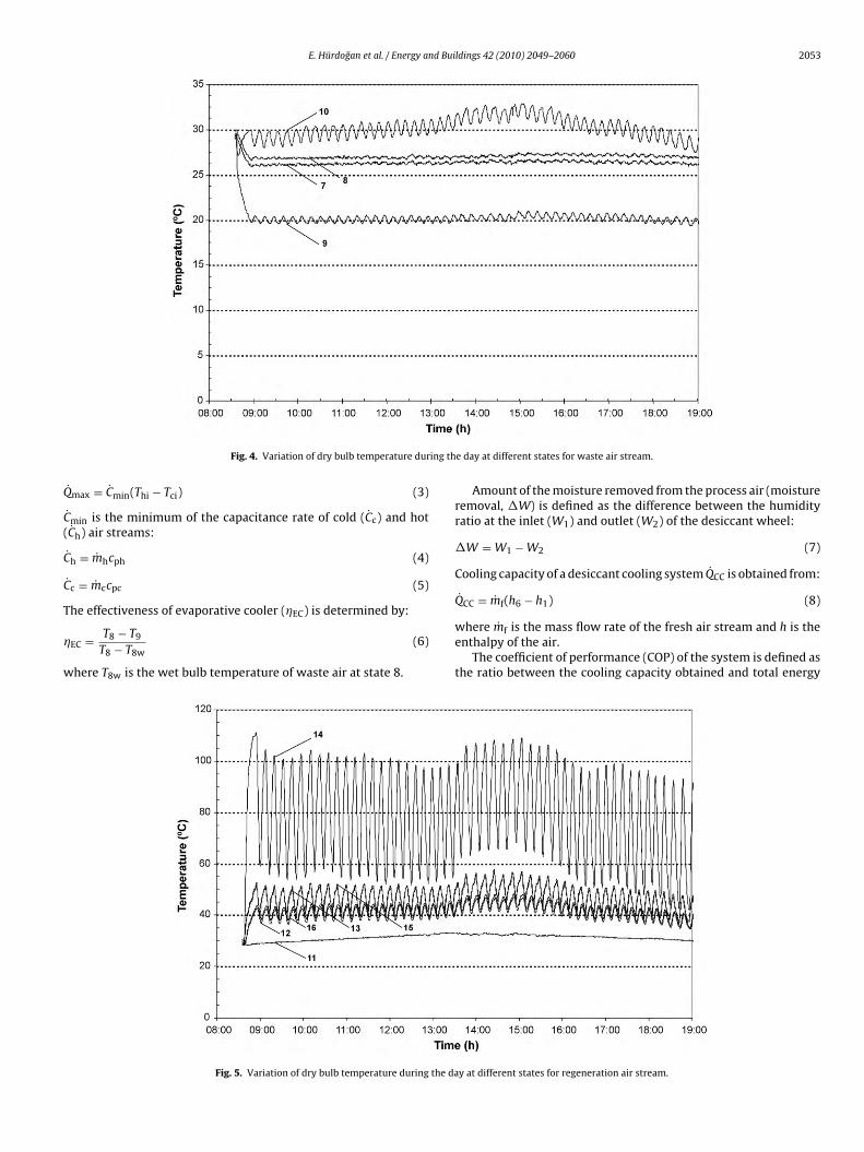
Fig. 4. Variation of dry bulb temperature dur
˙ max = Cmin(Thi − Tci) (3)
˙ min is the minimum of the capacitance rate of cold (Cc) and hotCh) air streams:
˙ h = mhcph (4)
˙ c = mccpc (5)
he effectiveness of evaporative cooler (�EC) is determined by:
EC = T8 − T9
T8 − T8w(6)
here T8w is the wet bulb temperature of waste air at state 8.
Fig. 5. Variation of dry bulb temperature during the da
e day at different states for waste air stream.
Amount of the moisture removed from the process air (moistureremoval, �W) is defined as the difference between the humidityratio at the inlet (W1) and outlet (W2) of the desiccant wheel:
�W = W1 − W2 (7)
Cooling capacity of a desiccant cooling system QCC is obtained from:
QCC = mf(h6 − h1) (8)
where mf is the mass flow rate of the fresh air stream and h is theenthalpy of the air.
The coefficient of performance (COP) of the system is defined asthe ratio between the cooling capacity obtained and total energy
y at different states for regeneration air stream.
2054 E. Hürdogan et al. / Energy and Buildings 42 (2010) 2049–2060
idity d
i
C
Efc
E
e
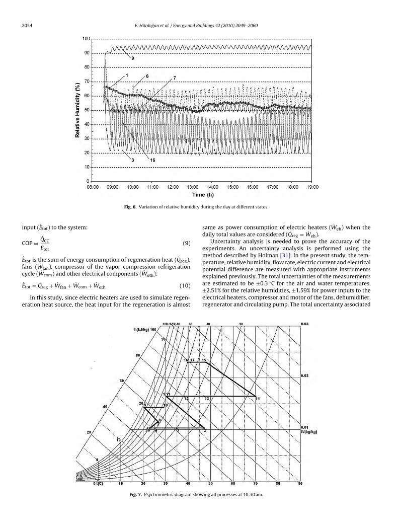
Fig. 6. Variation of relative hum
nput (Etot) to the system:
OP = QCC
Etot(9)
˙ tot is the sum of energy consumption of regeneration heat (Qreg),ans (Wfan), compressor of the vapor compression refrigeration
˙ ˙
ycle (Wcom) and other electrical components (Woth):˙ tot = Qreg + Wfan + Wcom + Woth (10)
In this study, since electric heaters are used to simulate regen-ration heat source, the heat input for the regeneration is almost
Fig. 7. Psychrometric diagram show
uring the day at different states.
same as power consumption of electric heaters (Weh) when thedaily total values are considered (Qreg = Weh).
Uncertainty analysis is needed to prove the accuracy of theexperiments. An uncertainty analysis is performed using themethod described by Holman [31]. In the present study, the tem-perature, relative humidity, flow rate, electric current and electricalpotential difference are measured with appropriate instruments
explained previously. The total uncertainties of the measurementsare estimated to be ±0.3 ◦C for the air and water temperatures,±2.51% for the relative humidities, ±1.59% for power inputs to theelectrical heaters, compressor and motor of the fans, dehumidifier,regenerator and circulating pump. The total uncertainty associateding all processes at 10:30 am.
E. Hürdogan et al. / Energy and Buildings 42 (2010) 2049–2060 2055
tive c
wtcr
4
oie
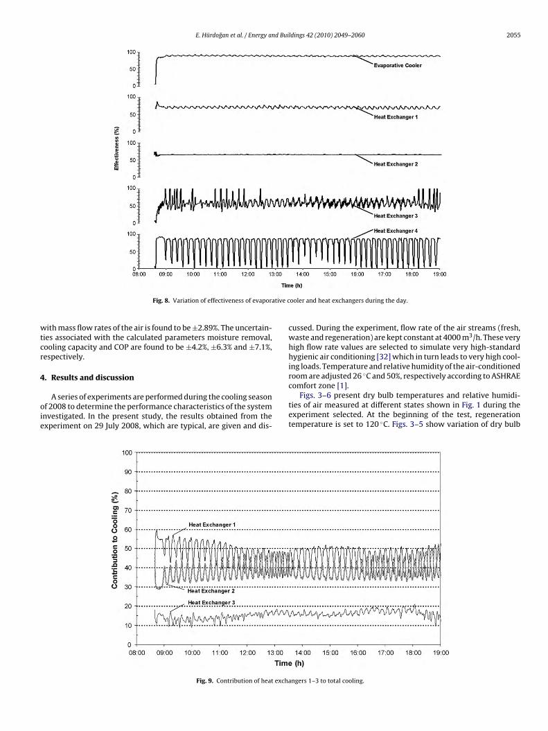
Fig. 8. Variation of effectiveness of evapora
ith mass flow rates of the air is found to be ±2.89%. The uncertain-ies associated with the calculated parameters moisture removal,ooling capacity and COP are found to be ±4.2%, ±6.3% and ±7.1%,espectively.
. Results and discussion
A series of experiments are performed during the cooling seasonf 2008 to determine the performance characteristics of the systemnvestigated. In the present study, the results obtained from thexperiment on 29 July 2008, which are typical, are given and dis-
Fig. 9. Contribution of heat excha
ooler and heat exchangers during the day.
cussed. During the experiment, flow rate of the air streams (fresh,waste and regeneration) are kept constant at 4000 m3/h. These veryhigh flow rate values are selected to simulate very high-standardhygienic air conditioning [32] which in turn leads to very high cool-ing loads. Temperature and relative humidity of the air-conditionedroom are adjusted 26 ◦C and 50%, respectively according to ASHRAE
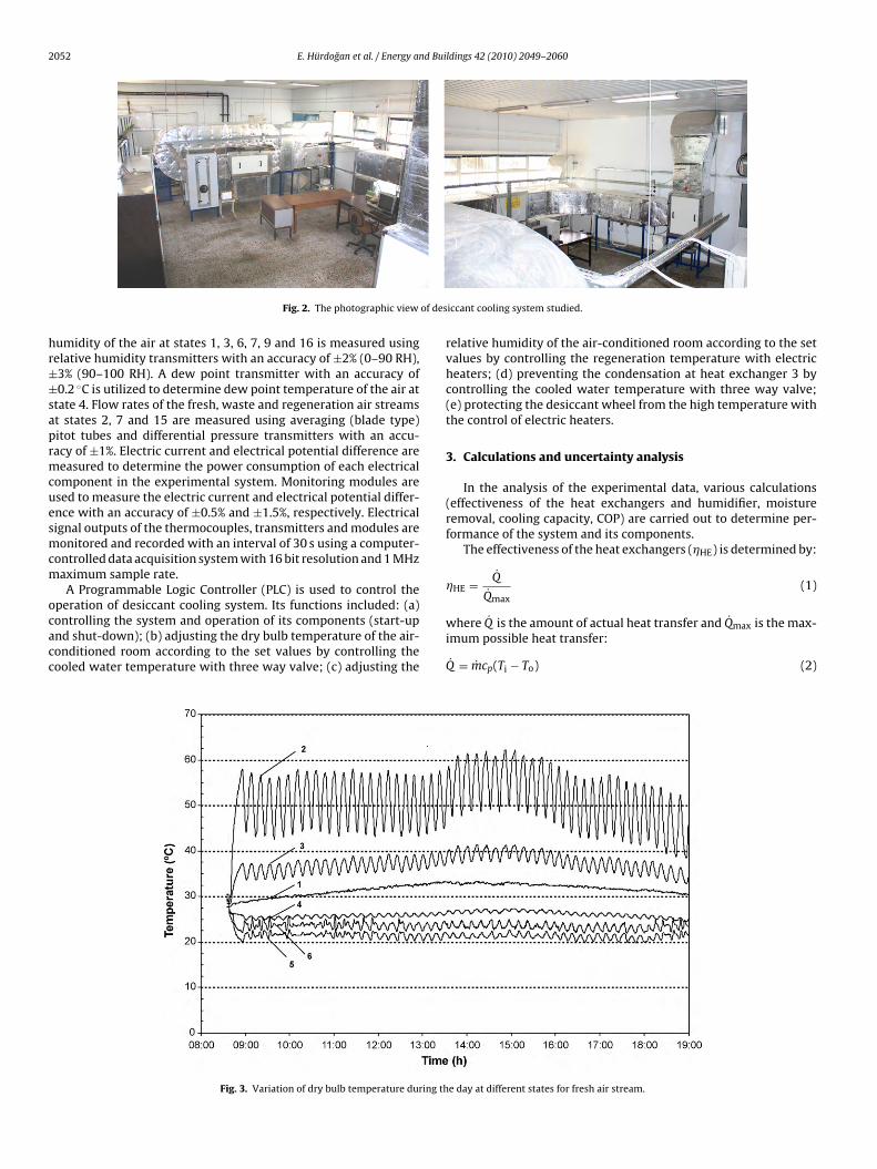
comfort zone [1].Figs. 3–6 present dry bulb temperatures and relative humidi-ties of air measured at different states shown in Fig. 1 during theexperiment selected. At the beginning of the test, regenerationtemperature is set to 120 ◦C. Figs. 3–5 show variation of dry bulb
ngers 1–3 to total cooling.
2056 E. Hürdogan et al. / Energy and Buildings 42 (2010) 2049–2060
and 4,
trutowr
s5p2
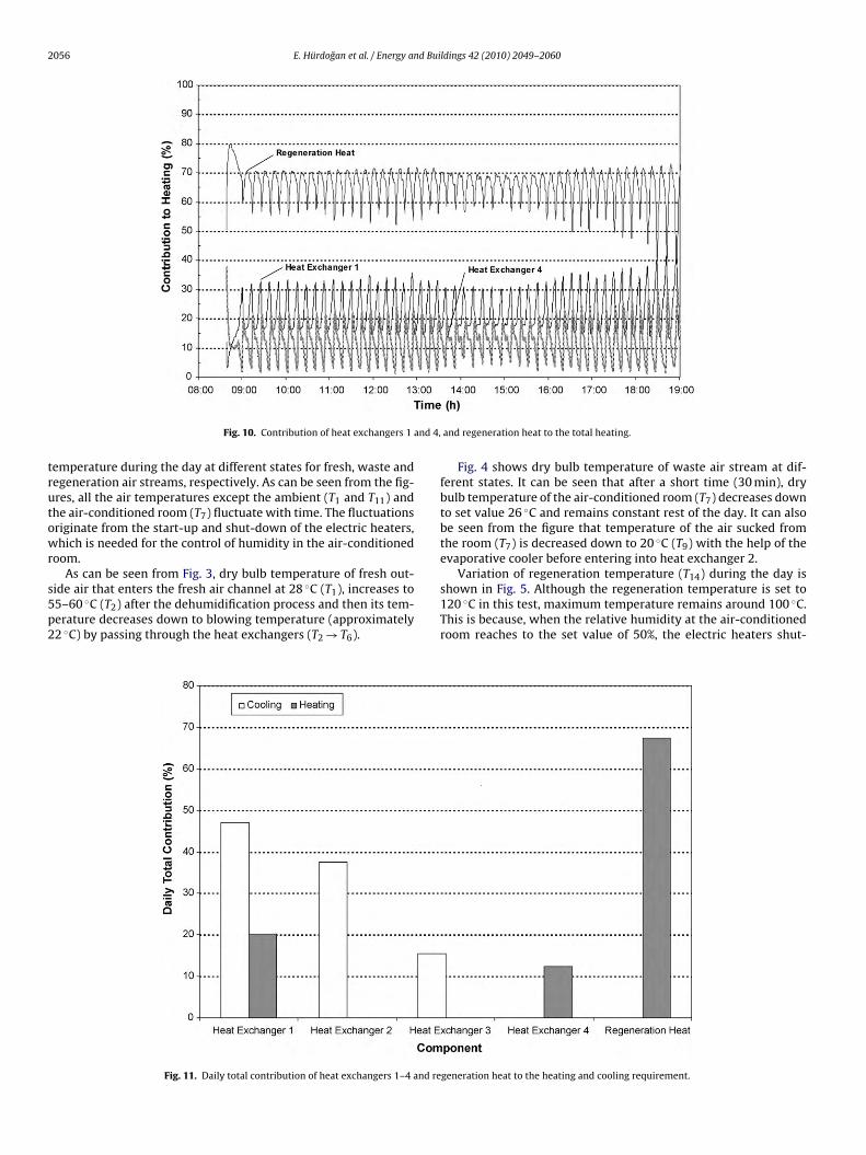
Fig. 10. Contribution of heat exchangers 1
emperature during the day at different states for fresh, waste andegeneration air streams, respectively. As can be seen from the fig-res, all the air temperatures except the ambient (T1 and T11) andhe air-conditioned room (T7) fluctuate with time. The fluctuationsriginate from the start-up and shut-down of the electric heaters,hich is needed for the control of humidity in the air-conditioned
oom.As can be seen from Fig. 3, dry bulb temperature of fresh out-
ide air that enters the fresh air channel at 28 ◦C (T1), increases to5–60 ◦C (T2) after the dehumidification process and then its tem-erature decreases down to blowing temperature (approximately2 ◦C) by passing through the heat exchangers (T2 → T6).
Fig. 11. Daily total contribution of heat exchangers 1–4 and re
and regeneration heat to the total heating.
Fig. 4 shows dry bulb temperature of waste air stream at dif-ferent states. It can be seen that after a short time (30 min), drybulb temperature of the air-conditioned room (T7) decreases downto set value 26 ◦C and remains constant rest of the day. It can alsobe seen from the figure that temperature of the air sucked fromthe room (T7) is decreased down to 20 ◦C (T9) with the help of theevaporative cooler before entering into heat exchanger 2.
Variation of regeneration temperature (T14) during the day is
shown in Fig. 5. Although the regeneration temperature is set to120 ◦C in this test, maximum temperature remains around 100 ◦C.This is because, when the relative humidity at the air-conditionedroom reaches to the set value of 50%, the electric heaters shut-generation heat to the heating and cooling requirement.
E. Hürdogan et al. / Energy and Buildings 42 (2010) 2049–2060 2057
ation
dr
aiwtIretp
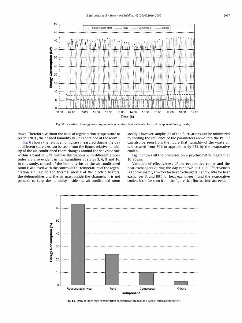
Fig. 12. Variation of energy consumption of regener
own. Therefore, without the need of regeneration temperature toeach 120 ◦C, the desired humidity value is obtained at the room.
Fig. 6 shows the relative humidities measured during the dayt different states. As can be seen from the figure, relative humid-ty of the air-conditioned room changes around the set value 50%
ithin a band of ±3%. Similar fluctuations with different ampli-udes are also evident in the humidities at states 3, 6, 9 and 16.n this study, control of the humidity inside the air-conditioned
oom is achieved with the control of the temperature of the regen-ration air. Due to the thermal inertia of the electric heaters,he dehumidifier and the air mass inside the channels, it is notossible to keep the humidity inside the air-conditioned roomFig. 13. Daily total energy consumption of regene
heat and each electrical component during the day.
steady. However, amplitude of the fluctuations can be minimizedby feeding the influence of the parameters above into the PLC. Itcan also be seen from the figure that humidity of the waste airis increased from 50% to approximately 95% by the evaporativecooler.
Fig. 7 shows all the processes on a psychrometric diagram at10:30 am.
Variation of effectiveness of the evaporative cooler and the
heat exchangers during the day is shown in Fig. 8. Effectivenessis approximately 65–75% for heat exchangers 1 and 2, 60% for heatexchanger 3, and 90% for heat exchanger 4 and the evaporativecooler. It can be seen from the figure that fluctuations are evidentration heat and each electrical component.
2058 E. Hürdogan et al. / Energy and Buildings 42 (2010) 2049–2060
ling c
itr
depemfb
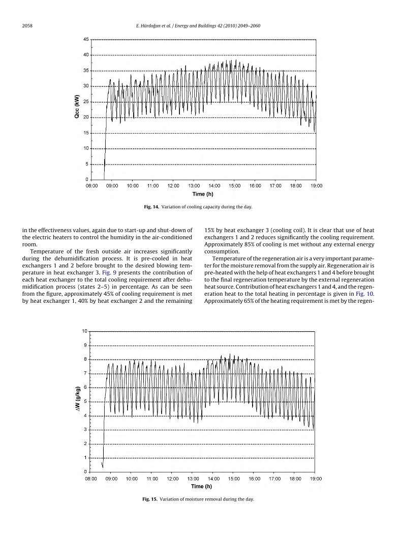
Fig. 14. Variation of coo
n the effectiveness values, again due to start-up and shut-down ofhe electric heaters to control the humidity in the air-conditionedoom.
Temperature of the fresh outside air increases significantlyuring the dehumidification process. It is pre-cooled in heatxchangers 1 and 2 before brought to the desired blowing tem-erature in heat exchanger 3. Fig. 9 presents the contribution of
ach heat exchanger to the total cooling requirement after dehu-idification process (states 2–5) in percentage. As can be seenrom the figure, approximately 45% of cooling requirement is mety heat exchanger 1, 40% by heat exchanger 2 and the remaining
Fig. 15. Variation of moisture
apacity during the day.
15% by heat exchanger 3 (cooling coil). It is clear that use of heatexchangers 1 and 2 reduces significantly the cooling requirement.Approximately 85% of cooling is met without any external energyconsumption.
Temperature of the regeneration air is a very important parame-ter for the moisture removal from the supply air. Regeneration air ispre-heated with the help of heat exchangers 1 and 4 before brought
to the final regeneration temperature by the external regenerationheat source. Contribution of heat exchangers 1 and 4, and the regen-eration heat to the total heating in percentage is given in Fig. 10.Approximately 65% of the heating requirement is met by the regen-removal during the day.
E. Hürdogan et al. / Energy and Buildings 42 (2010) 2049–2060 2059
nt of p
e4a
eib
atarte
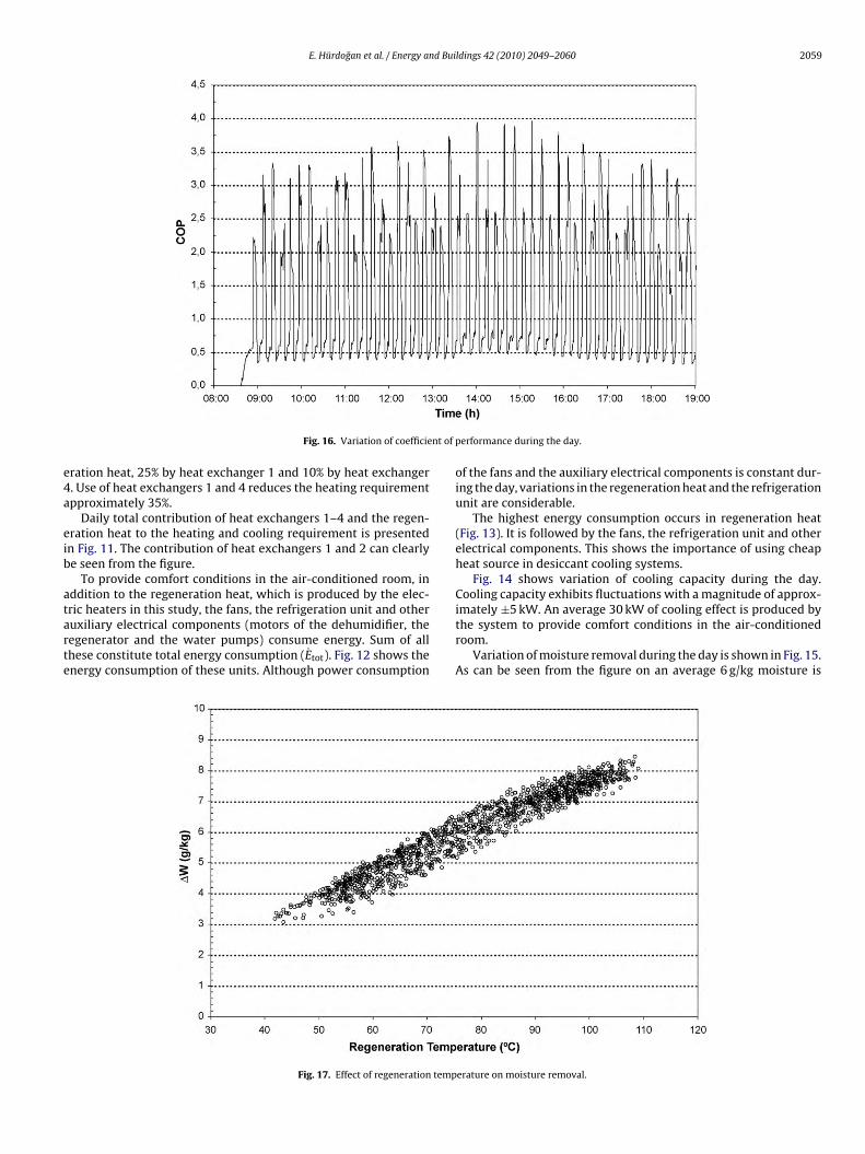
Fig. 16. Variation of coefficie
ration heat, 25% by heat exchanger 1 and 10% by heat exchanger. Use of heat exchangers 1 and 4 reduces the heating requirementpproximately 35%.
Daily total contribution of heat exchangers 1–4 and the regen-ration heat to the heating and cooling requirement is presentedn Fig. 11. The contribution of heat exchangers 1 and 2 can clearlye seen from the figure.
To provide comfort conditions in the air-conditioned room, inddition to the regeneration heat, which is produced by the elec-
ric heaters in this study, the fans, the refrigeration unit and otheruxiliary electrical components (motors of the dehumidifier, theegenerator and the water pumps) consume energy. Sum of allhese constitute total energy consumption (Etot). Fig. 12 shows thenergy consumption of these units. Although power consumptionFig. 17. Effect of regeneration temp
erformance during the day.
of the fans and the auxiliary electrical components is constant dur-ing the day, variations in the regeneration heat and the refrigerationunit are considerable.
The highest energy consumption occurs in regeneration heat(Fig. 13). It is followed by the fans, the refrigeration unit and otherelectrical components. This shows the importance of using cheapheat source in desiccant cooling systems.
Fig. 14 shows variation of cooling capacity during the day.Cooling capacity exhibits fluctuations with a magnitude of approx-
imately ±5 kW. An average 30 kW of cooling effect is produced bythe system to provide comfort conditions in the air-conditionedroom.Variation of moisture removal during the day is shown in Fig. 15.As can be seen from the figure on an average 6 g/kg moisture is
erature on moisture removal.
2 d Bui
re
Fevt
rrdcrrtw
f
5
aaic
1
2
3
4
5
A
p(P
R
[
[
[
[
[
[
[
[
[
[
[
[
[
[
[
[
[
[
[
[
[
cant for reducing energy use of an air conditioning room, Energy and Buildings42 (2010) 315–325.
[31] J.P. Holman, Experimental Methods for Engineers, fifth edn, McGraw Hill, NY,
060 E. Hürdogan et al. / Energy an
emoved from the ambient air in the desiccant wheel during thexperiment.
Coefficient of performance (COP) of the system is shown inig. 16. Although COP changes between 0.4 and 4 according to thelectric heaters switching on or off, the daily mean value is 1.35. Thisalue is in the range of the COP values reported in the literature forhese kinds of systems [9,12].
In this study, control of the humidity inside the air-conditionedoom is achieved with the control of the temperature of theegeneration air. Therefore, regeneration temperature changesuring the experiment according to the humidity inside the air-onditioned room. Effect of regeneration temperature on moistureemoval is shown in Fig. 17, which contains 1250 data points rep-esenting the experiment selected. As can be seen from the figure,he moisture removed from the fresh air increases almost linearlyith the increase of regeneration temperature.
Similar results are obtained from the other experiments per-ormed during the cooling season of 2008.
. Conclusion
A novel desiccant based air conditioning system is developednd initially tested. In the system studied, the moisture of the freshir is reduced passing it through a solid desiccant wheel and thents temperature decreased by the “dry coil” of a vapor compressionycle. The following main conclusions emerged from this study:
. Using a heat exchanger (heat exchanger 4), which is not used inthis type of systems, for pre-heating the regeneration air withexhaust air is feasible to install. Moreover, heat pollution to theenvironment can be decreased with this heat exchanger.
. Approximately 45% of cooling requirement is met by heatexchanger 1, 40% by heat exchanger 2 and the remaining 15%by heat exchanger 3 (cooling coil). It is clear that use of heatexchangers 1 and 2 reduces significantly the cooling require-ment.
. Approximately 65% of the heating requirement is met by theregeneration heat source, 25% by heat exchanger 1 and 10% byheat exchanger 4. Use of heat exchangers 1 and 4 reduces theheating requirement approximately 35%.
. The highest energy consumption occurs in regeneration heat.This shows the importance of using a cheap heat source in des-iccant cooling systems.
. Although COP changes between 0.4 and 4 according to the elec-tric heaters switching on or off, the daily mean value is 1.35.
cknowledgements
The authors would like to acknowledge the financial sup-ort of the Scientific & Technological Research Council of TurkeyTÜBITAK) with project number 106M094 and Academic Researchroject Units of Cukurova University.
eferences
[1] ASHRAE, Handbook of Fundamental, American Society of Heating, Refrigeratingand Air Conditioning Engineers, Inc, Atlanta, USA, 2001.
[2] A.V. Arundel, E.M. Sterling, J.H. Bigging, T.D. Sterling, Indirect health effects ofrelative humidity in indoor environments, Environmental Health Perspectives65 (1986) 351–361.
[
ldings 42 (2010) 2049–2060
[3] K. Abe, Evaluation of fungal growth at the air outlet and inlet of air conditioners,Indoor Air 3 (1996) 185–190.
[4] A.L. Hines, T.K. Ghosh, S.K. Loyalka, R.C. Warder, Investigation of co-sorption ofgases and vapors as a means to enhance indoor air quality-phase 2: removalof particulates and airborne micro-organisms by solid adsorbents and liquiddesiccants. Report of Gas Research Institute, 1992, GRI-92/0157.5.
[5] J.A. Phillips, M.B. Wagner, Antiseptic Effects of Desiccant Based HVAC Systems,Lehigh University, Bioprocessing Institute, 1994.
[6] B. Kovak, P.R. Heimann, The sanitizing effects of desiccant-based cooling,ASHRAE Journal 39 (1997) 60–64.
[7] M.D. Larranaga, The capability of a solid sorbent desiccant unit at removingselected indoor air quality-related microorganisms from the air, PhD Thesis,Graduate Faculty of Texas Tech University, 2004.
[8] L. Fang, G. Zhang, A. Wisthaler, Desiccant wheels as gas-phase absorption (GPA)air cleaners: evaluation by PTR-MS and sensory assessment, Indoor Air 18(2008) 375–385.
[9] D.G. Waugaman, A. Kini, C.F. Kettleborough, A review of desiccant cooling sys-tems, Journal of Energy Resources Technology 115 (1) (1993) 1–8.
10] P. Mazzei, F. Minichiello, D. Palma, HVAC dehumidification systems for thermalcomfort: a critical review, Applied Thermal Engineering 25 (2004) 677–707.
11] K. Daou, R.Z. Wang, Z.Z. Xia, Desiccant cooling air conditioning: a review,Renewable and Sustainable Energy Reviews 10 (2006) 55–77.
12] D. La, Y.J. Dai, Y. Li, R.Z. Wang, T.S. Ge, Technical development of rotary desiccantdehumidification and air conditioning: a review, Renewable and SustainableEnergy Reviews 14 (2010) 130–147.
13] J.J. Jurinak, J.W. Mitchell, W.A. Beckman, Open-cycle desiccant air condition-ing as an alternative to vapor compression cooling in residential applications,Journal of Solar Energy Engineering 106 (1984) 252–260.
14] P.L. Dhar, S.K. Singh, Studies on solid desiccant based hybrid air-conditioningsystems, Applied Thermal Engineering 21 (2001) 119–134.
15] C.X. Jia, Y.J. Dai, J.Y. Wu, R.Z. Wang, Analysis on a hybrid desiccant air-conditioning system, Applied Thermal Engineering 26 (2006) 2393–2400.
16] N.A. Pennington, Humidity changer for air conditioning, US Patent No.2,700,537 (1955).
17] R.V. Dunkle, A method of solar air conditioning, Mechanical and Chemical Engi-neering Transactions of the Institute of Engineers 73 (1965) 73–78.
18] I.L. Maclaine-Cross, A theory of combined heat and mass transfer in regenera-tions, PhD Thesis, Monash University, 1974.
19] S. Jain, P.L. Dhar, S.C. Kaushik, Evaluation of solid desiccant based evapora-tive cooling cycles for typical hot and humid climates, International Journal ofRefrigeration 18 (5) (1995) 287–296.
20] K. Ando, A. Kodama, T. Hırose, M. Goto, H. Okano, Experimental study on aprocess design for adsorption desiccant cooling driven with a low-temperatureheat, Adsorption 11 (2005) 631–636.
21] H. Zhang, J. Niu, A two-stage desiccant cooling system using low-temperatureheat, Building Services Engineering Research Technology 20 (2) (1999) 51–55.
22] T.S. Ge, Y. Li, R.Z. Wang, Y.J. Dai, Experimental study on a two-stage rotary desic-cant cooling system, International Journal of Refrigeration 32 (2009) 498–508.
23] T.S. Ge, Y.J. Dai, R.Z. Wang, Y. Li, Experimental investigation on a one-rotortwo-stage rotary desiccant cooling system, Energy 33 (2008) 1807–1815.
24] Y.S. Tsay, S. Kato, R. Ooka, M. Koganei, K. Nishida, K. Kawamoto, Study on noncondensing air conditioning system performance when combining a desiccantcooling system with a CO2 heat pump, HVAC&R Research (2006) 917–933,Special Issue 12 (3c).
25] S.P. Halliday, C.B. Beggs, P.A. Sleigh, The use of solar desiccant cooling in theUK: a feasibility study, Applied Thermal Engineering 22 (2002) 1327–1338.
26] A. Kodama, M. Ohkura, T. Hirose, M. Goto, An energy flow analysis of a solardesiccant cooling equipped with a honeycomb adsorber, Adsorption 11 (2005)597–602.
27] A.E. Kabeel, Solar powered air conditioning system using rotary honeycombdesiccant wheel, Renewable Energy 32 (11) (2007) 1842–1857.
28] N. Enteria, H. Yoshino, A. Mochida, R. Takaki, A. Satake, R. Yoshie, T. Mitamura,S. Baba, Construction and initial operation of the combined solar thermal andelectric desiccant cooling system, Solar Energy 83 (2009) 1300–1311.
29] P. Bourdoukan, E. Wurtz, P. Joubert, Experimental investigation of a solar des-iccant cooling installation, Solar Energy 83 (2009) 2059–2073.
30] Y. Sukamongkol, S. Chungpaibulpatana, B. Limmeechokchai, P. Sripadungtham,Condenser heat recovery with a PV/T air heating collector to regenerate desic-
1989.32] ASHRAE, Handbook of HVAC Applications, American Society of Heating, Refrig-
erating and Air Conditioning Engineers, Inc, Atlanta, USA, 2003.