cooling system
TRANSCRIPT

CHAPTER ONE
INTRODUCTION
1.0 Introduction to siwes
The student industrial work experience scheme (siwes).it is
skill training Programmed which is for the award of various
degrees, diplomas etc. Across all tertiary institution.
The sole aim amongst other objectives of the national policy
on education (NPE) is to build a self-reliant nation. The
nation has to train its citizens adequately to meet the
challenge of the fast changing and growing industrial
technology in other to achieve the stated objective. The
students of vocational and technology institutions on the
other hand need to be exposed to the realities of work
required in their various field of study.
The students industrial work experience scheme (SIWES) is
mandatory to every student of the university of technology by
the Nigeria University of what they have been taught and
learnt in theory and practical; which exposes them to the use
of machinery, tools, equipment and materials, and with the way
and manner of operations performed in the world at large, that
is, outside the classroom and also to prepare the students to
life after graduation.

The students industrial work experience scheme (SIWES) is
designed for students of tertiary institutions to promote and
encourage the acquisition of skills and practical knowledge
relevant to their field of specialization.
As part of the industrial training fund (ITF)
responsibilities, students industrial work experience (SIWES)
was designed to build capacity for graduate’s self-employment
in the context of small scale industrialization, in the
economy, through on-the-job training in industries and
commerce compatible with their area of study.
The program (SIWES) is designed to meet the following
objective;
- Encourage relationship between industry and school.
- Bridge the gap between practical aid related theories.
- Enable the students to manipulation their skills.
- Prepare the students for future employment.
1.1 Purpose of siwes
It is mainly aim to bridge the gap between the
theoretical aspect learned in
Colleges, polytechnics and universities and the practical
aspect in industry
Training i.e. applying what is learnt in school into
practical in the industry.

It explores student to machine tools and equipment in
professional work method.
1.2 Objective of siwes
1. It equips the students with industrial skill i.e.
mainly practical and experience
In their courses of safety.
2. Expose students to work method and techniques that may
not be found in
Polytechnics, colleges or universities.
3. Links the student to work experience that they may
likely meet after gradually
4. Provides student with the opportunities to apply
their theoretical knowledge in real world situation
thereby bridging the gap between
High education and actual practice. Makes transition from
the institution to
The world of work easier and thus enhance students
contact for later job placement after grad

COOLING SYSTEMSMCS – 1350This engine has a pressure type cooling system that is equipped with a shunt line. A pressure type cooling system offers two advantages:
1.The cooling system can operate safely at a temperature that is higher than the boiling pointof water.
2.The cooling system prevents cavitations in the water point.
Cavitations is the sudden formation of low pressure bubbles in liquids by mechanical forces. The formation of air or stream pockets is more difficult within a pressure type cooling system.
The shunt line prevents cavitation by the water pump.The shunt line provides a constant flow of coolant tothe water pump.NOTE: In air-to-air after cooled systems, a coolant mixture with a minimum of 30 percent ethylene glycol base antifreeze must be used for efficient water pumpperformance. This mixture keeps the cavitation temperature range of coolant high enough for efficient performance.
ILLUSTRATION 1(1) Cylinder head(2) Water temperature regulator housing(3) Expansion tank(4) Bypass hose(5) Cylinder block

(6) Oil cooler(7) Water pump(8) Radiator
Water pump (7) is located on the right side ofthe cylinder block. The water pump is driven by a belt that is powered by the crankshaft pulley. Coolant can enter the water pump in three places:1.Inlet at the bottom of the water pump2.Bypass hose (4) which is located on the top of
the water pump3.Shunt line which is located on the top of the
water pump
Coolant from the bottom of the radiator is pulled into the bottom inlet of the pump by impeller rotation. The cooler exits the back of the pump directly into the oil cooler cavity of the block. Allof the coolant passes through the core of the oil cooler and the coolant enters the internal water manifold of the cylinder block. The manifold disperses the coolant to water jackets around the cylinder walls.ILLUSTRATION 2(7) Water pump(9) Byepass inlet
ILLUSTRATION 3(1) Cylinder head(2)Water temperature regulator housing(4)Bypass hose(10)Water temperature regulator
From the cylinder block, the coolant flows into passages in the cylinder head. The passages send the flow around the unit injector sleeves and the
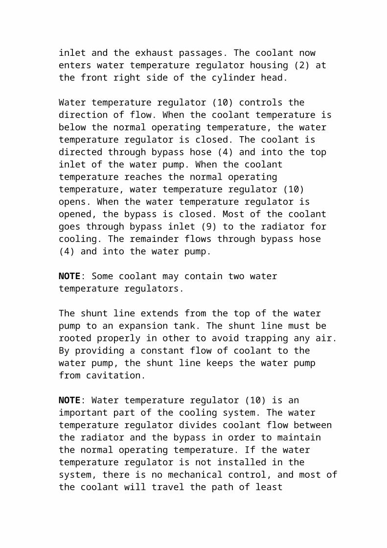
inlet and the exhaust passages. The coolant now enters water temperature regulator housing (2) at the front right side of the cylinder head.
Water temperature regulator (10) controls the direction of flow. When the coolant temperature is below the normal operating temperature, the water temperature regulator is closed. The coolant is directed through bypass hose (4) and into the top inlet of the water pump. When the coolant temperature reaches the normal operating temperature, water temperature regulator (10) opens. When the water temperature regulator is opened, the bypass is closed. Most of the coolant goes through bypass inlet (9) to the radiator for cooling. The remainder flows through bypass hose (4) and into the water pump.
NOTE: Some coolant may contain two water temperature regulators.
The shunt line extends from the top of the water pump to an expansion tank. The shunt line must be rooted properly in other to avoid trapping any air.By providing a constant flow of coolant to the water pump, the shunt line keeps the water pump from cavitation.
NOTE: Water temperature regulator (10) is an important part of the cooling system. The water temperature regulator divides coolant flow between the radiator and the bypass in order to maintain the normal operating temperature. If the water temperature regulator is not installed in the system, there is no mechanical control, and most ofthe coolant will travel the path of least

resistance through the bypass. This will cause the engine to overheat in hot weather and the engine will not reach normal operating temperature in coldweather.
NOTE: The air vent valve will allow the air to escape past the water temperature regulator from the cooling system while the radiator is being filled. During normal operation, the air vent valvewill be closed in order to prevent coolant flow past the water temperature regulator.
COOLANT FOR AIR COMPRESSOR (IF EQUIPPED)
ILLUSTRATION 4(11) Coolant supply line(12) Coolant return line
If the engine is equipped with an air compressor, coolant for the air compressor is supplied from thewater temperature regulator housing, through coolant supply line (11). The coolant is circulatedthrough the air compressor and the coolant is returned to the cooling system through coolant return line (12) into the cylinder head.
COOLANT CONDITIONER (IF EQUIPPED)
Some conditions of operation can cause pitting. This pitting is caused by corrosion or by cavitation erosion. A corrosion inhibitor is a chemical that provides a reduction in pitting. The addition of a corrosion inhibitor can keep this type of damage to a minimum.
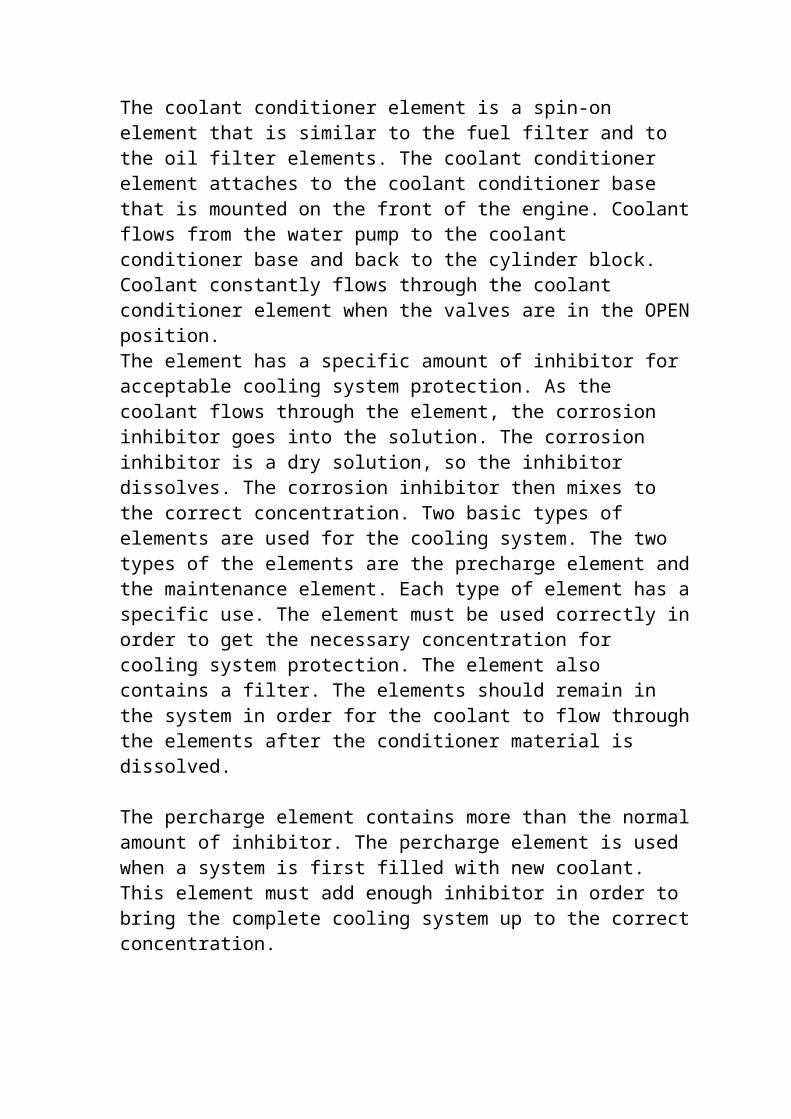
The coolant conditioner element is a spin-on element that is similar to the fuel filter and to the oil filter elements. The coolant conditioner element attaches to the coolant conditioner base that is mounted on the front of the engine. Coolantflows from the water pump to the coolant conditioner base and back to the cylinder block. Coolant constantly flows through the coolant conditioner element when the valves are in the OPENposition.The element has a specific amount of inhibitor for acceptable cooling system protection. As the coolant flows through the element, the corrosion inhibitor goes into the solution. The corrosion inhibitor is a dry solution, so the inhibitor dissolves. The corrosion inhibitor then mixes to the correct concentration. Two basic types of elements are used for the cooling system. The two types of the elements are the precharge element andthe maintenance element. Each type of element has aspecific use. The element must be used correctly inorder to get the necessary concentration for cooling system protection. The element also contains a filter. The elements should remain in the system in order for the coolant to flow throughthe elements after the conditioner material is dissolved.
The percharge element contains more than the normalamount of inhibitor. The percharge element is used when a system is first filled with new coolant. This element must add enough inhibitor in order to bring the complete cooling system up to the correctconcentration.

The maintenance elements have a normal amount of inhibitor. The maintenance elements are installed at the first change interval. A sufficient amount of inhibitor is provided by the maintenance element, in order to maintain the corrosion protection at an acceptable level. After the first change interval, only maintenance elements are installed. In order to provide the cooling system with protection, maintenance elements are installedat specific intervals.
NEGATIVE FLOW CONTROL SYSTEM
SMCS – 5050-NE
INTRODUCTION
The drive pump and the idler pump receive signal oil pressure from the centre bypass passages of main control valve. This signal oil pressure that is created in the center bypass passages of the main control valve is called negative flow control pressure. Negative flow control pressure flows to the regulators at the drive pump and the idler pumpto control the output flow of the pumps. Negative flow control pressure is created during the following machine operating conditions.
1.All of the joysticks and travel levers/pedals arein the NEUTRAL position.
2.Any of the joysticks and/or travel levers/pedals are partially moved from the NEUTRAL position to perform a fine control operation.
3.A boom lower operation is performed alone.

ILLUSTRATION 1
Main control valve (top view)(12) Negative flow control line to idler pump(13) Negative flow control line to drive pump
The right body of the control valve receives supplyoil from the drive pump. Negative flow control pressure from the right body of the main control valve flows through negative flow control line (13)to the drive pump. The left body of the control valve receives supply oil from the idler pump. Negative flow control pressure from the left body of the main control valve flows through negative flow control line (12) to the idler pump. The negative flow control operation of the drive pump and the idler pump is identical.ILLUSTRATION 2
Negative flow control operation (control valves in the NEUTRAL position)(1) Center bypass passage(2) Return line(3) Center bypass passage(4) Passage(5) Relief valve (negative flow control)(6) Relief valve (negative flow control)(7) Negative flow control orifice(8) Port(9) Negative flow control orifice(10) Passage(11) Return passage(12) Negative flow control line(13) Negative flow control line(14) Idler pump

(15) Drive pump(16) Pilot pump
ILLUSTRATION 3
Work tool control valve (NEUTRAL position)
(3)Center bypass passage
Illustration 3 shows the negative flow control operation at the main control valve when all of the control valves are in the NEUTRAL position. When all of the joystick and the travel levers/pedals are in the NEUTRAL position, the spools of the individual control valves are in the NEUTRAL position. Oil flow to the cylinders and motors is blocked. Center bypass passages (1)and (3) are open.
All of the oil delivery from drive pump (15) flows through center bypass passage (3), Passage (4) and negative flow control orifice (9) to return line (2). Negative flow control orifice (9) restricts the oil flow. The pressure in passage (4) increases. Increased negative controlpressure now flows through passage (10) and negative flow control line (13) to the pump regulator. The negative flow control operation ofthe drive pump regulator causes the swashplate ofthe drive pump to move to the minimum angle position. The output flow of the drive pump is decreased due to the increased negative flow control pressure that is created in center bypasspassage (3).

Since center bypass passage (1) is also open, thenegative flow control operation of the idler pumpregulator is identical to the negative flow control operation of the drive pump regulator.
REFERENCE: For more information concerning the negative flow control operation of the main pump regulators, refer to systems operation, ‘pump control (main hydraulic) (main pump regulator)’’.
ILLUSTRATION 4
Negative flow control operation (work tool control valve in the WORK TOOL CLOSE position)(1) Center bypass passage(2) Return line(3) Center bypass passage(4) Passage(5) Relief valve (negative flow control)(6) Relief valve (negative flow control)(7) Negative flow control orifice(8) Port(9) Negative flow control orifice(10)Passage(11)Return passage(12)Negative flow control line(13)Negative flow control line(14)Idler pump(15)Drive pump(16)Pilot pump
ILLUSTRATION 5
Work tool control valve (WORK TOOL CLOSE position)

(3)Center bypass passage
Illustration 5 shows the negative flow control operation at the main control valve when only thework tool control valve is in the WORK TOOL CLOSEposition
All of the control valves in the left body of thecontrol valve are in the NEUTRAL position. Centerbypass passage (1) is open. All of the oil delivery from the idler pump flows through centerbypass passage (1)to negative flow control orifice (7).Since all of the oil delivery from idler pump(14)is restricted by negative flow control office (7),negative flow control pressure(PN) in center bypass passage (1)is at maximum pressure. The negative flow control pressure flows through negative flow control line (12) to the idler pump regulator. The negative flow control operation of the idler pump regulator causes the swashplate of the idler pump to move to the minimum angle position. The output flow ofthe idler pump is decreased due to the increased negative flow control pressure that is created incenter bypass passage (1).The joystick for the work tool has been moved fully to the WORK TOOL CLOSE position. Pilot oil has fully shifted the work tool control valve. The oil delivery from drive pump (15) flows into the right body of the main control valve. The oil delivery flows through center bypass passage (3 ) to the work tool control valve. Since the spool in the work tool control valve is fully shifted, centre bypass passage (3) is blocked. All of the oil delivery from the drive pump flows to the head end of the work tool cylinder . No oil flows to

negative flow control orifice (9) and no negativeflow control pressure is created in center bypasspassage (3). Since no negative flow control pressure is sent to the drive pump regulator, thepump regulator moves the swashplate of the drive pump toward the maximum angle position. The output flow of the drive pump is increased since no negative flow control pressure is created in center bypass passage (3).
FINE CONTROL OPERATION
ILLUSTRATION 6
Work tool control valve (fine control)(3)Center bypass passage(21)Parallel feeder passage(22)Port(23)Spool(24)Passage(P) Pilot pressure
When the joystick for the work tool is in the NEUTRAL position, spool (23) is in the NEUTRAL position. The oil delivery from the drive pump flows through center bypass passage (3) to negative flow control orifice (9). When the joystick for the work tool is partially moved from the NEUTRAL position to perform a fine control operation, pilot pressure (P) enters the control valve at the pilot port. Pilot pressure shifts spool (23) slightly to the left. The movement of spool (23) partially opens passage (24). Center bypass passage (3) is partially blocked.

The oil delivery from the drive pump is now divided into two flow paths. A portion of the oildelivery from the drive pump flows through center bypass passage (3) to negative flow control orifice (9). The remainder of the oil delivery from the drive pump flows through parallel feeder passage (21) and passage (24) to port (22). The oil flow center bypass passage (3 )to negative flow control orifice (9) decreases. The flow resistance through the negative flow control orifice decreases and the negative flow control pressure (PN) in passage (4) decreases. The negative flow control pressurethat is sent to the regulator at the drive pump decreases. The pump regulator causes the swashplate of the pump to move towards the maximum angle position. The output flow of the pump is increased due to the decrease in negativeflow control pressure (PN).
When the joystick for the work tool is moved to the full stroke position, spool(23) shifts fully to the left. Center bypass passage (3) is now blocked by spool (23). Since there is no oil flowthrough center bypass passage (24), no negative control pressure is created. The swashplate of the drive pump is moved to the maximum angle position. The output flow of the drive pump is maximum. The output flow of the drive pump is nowcontrolled by the constant horsepower flow control.
The ability to modulate the negative flow controlpressure by partial movement of the joystick enables fine control of the implements.

RELIEF VALVE (NEGATIVE FLOW CONTROL)
ILLUSTRATION 7
(2). Return line(3). Center bypass passage(4). Passage(5).Relief valve for negative flow control(9).Negative flow control orifice(11).Return passage(17).Plug(18).Spring(19).Relief valve body(20).Valve(PN) Negative flow control pressure
The following description is given for the relief of the operation valve that is located in the rightbody of the main control valve. The operation of the relief valve for the negative flow control thatis located in the left body of the main control valve is identical.
Relief valve (5) for the negative flow control consists of plug (17), spring (18), relief valve body (19), and valve (20). When any one of the joysticks and/or travel levers/pedals is at full stroke position, the oil flow through center bypasspassage (3) is blocked. No oil flows to the relief valve for the negative flow control.
When all of the joysticks and/or travel levers/ pedals are suddenly returned to NEUTRAL position, all of the output flow from the drive pump flows through center bypass passage (3). The negative

flow control pressure in center bypass passage (3) and passage (4) suddenly increases.When the negative flow control pressure becomes higher than the pressure setting of relief valve (5) for the negative flow control,valve (20) shjfts to the leftagainst the force of spring (18). Oil in center bypass passage (3) is now allowed to flow past valve (20) into return passage (11) to the hydraulic shock that occurs due to sudden changes in negative flow control pressure.
After the hydraulic shock is relieved by the reliefvalve for the negative flow control, the force of spring (18) shifts valves (20) to the right. All ofthe output flow from the drive pump flows through center bypass passage (3), negative flow control orifice (9) and return line (2) to the hydraulic tank.
Negative flow control pressure (PN), that is created in center bypass passage (3), reaches maximum pressure since all of the oil flow is restricted by negative flow control orifice (9).Thenegative flow control pressure flows to the drive pump regulator. The regulator at the drive pump causes the swashplate of the drive pump to move theminimum angle position. The output flow of the drive pump is decreased due to the increase in negative flow control pressure (PN).
ILLUSTRATION 2
Pressure reducing valves on the pilot control valve
(2)Shuttle valve
(3)Primary pressure reducing valve

(4)Secondary pressure reducing valve
The pilot valve has two pressure reducing valves. Both valves are catridge types valves. Primary pressure reducing valve (3) reduces the pressure from the pilot pump to 3450±200 kPa (500±30 psi). This is the primary pilot system pressure.
Secondary pressure reducing valve (4) receives oil from the left cylinder. Secondary pressure reducingvalve (4) is used to provide pilot oil when the engine is stopped. The pressure of this oil is reduced to 2070±200 kPa (300±30 psi).Shuttle valve (2) senses the two reduced pressures. Then, the shuttle valve sends oil from the source of higher pressure through the pilot valve.
PILOT SOLENOID VALVES
ILLUSTRATION 3
Components of the proportional solenoid valve
(17)Catridge assembly
(18)Coil assembly
(19)Nut
The pilot valve contains an on/off solenoid valve which controls the flow of pilot oil to the proportional solenoid valves. The proportional solenoid valves send oil to the main control valve.

The output pressure is controlled electronically bythe electronic control module. The output pressure is proportional to the position of the implement control lever. As the implement control lever is moved farther away from the HOLD position, the output pressure increases. This causes the appropriate valve spool in the main control valve to shift farther so that more oil is allowed to flow to the implement cylinders.
PILOT RELIEF VALVE
The pilot relief valve controls the pressure in thepilot oil system. The pilot relief valve is in the pilot valve.
CHECK VALVE
ILLUSTRATION 4
Components of the check valve
(20) Inlet passage
(21) Valve
(22) Spring
(23) Holes
(24) Outlet passage
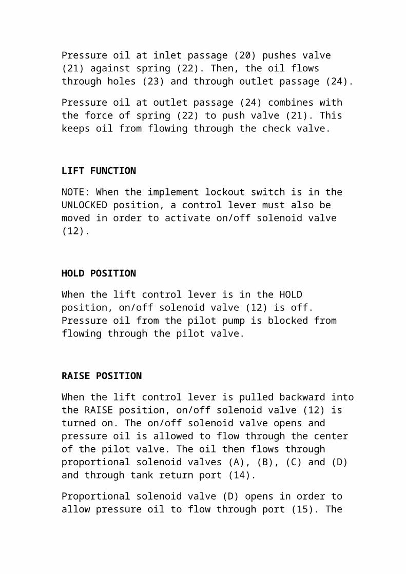
Pressure oil at inlet passage (20) pushes valve (21) against spring (22). Then, the oil flows through holes (23) and through outlet passage (24).
Pressure oil at outlet passage (24) combines with the force of spring (22) to push valve (21). This keeps oil from flowing through the check valve.
LIFT FUNCTION
NOTE: When the implement lockout switch is in the UNLOCKED position, a control lever must also be moved in order to activate on/off solenoid valve (12).
HOLD POSITION
When the lift control lever is in the HOLD position, on/off solenoid valve (12) is off. Pressure oil from the pilot pump is blocked from flowing through the pilot valve.
RAISE POSITION
When the lift control lever is pulled backward intothe RAISE position, on/off solenoid valve (12) is turned on. The on/off solenoid valve opens and pressure oil is allowed to flow through the center of the pilot valve. The oil then flows through proportional solenoid valves (A), (B), (C) and (D) and through tank return port (14).
Proportional solenoid valve (D) opens in order to allow pressure oil to flow through port (15). The

oil goes into the chamber to the RAISE end of the lift valve spool. As the pressure in the chamber increases, the valve spool shifts and oil is allowed to flow to the head end of the cylinders. Oil also flows from the rod end of the lift cylinders to the hydraulic tank through the lift valve spool.
As the lift control lever is pulled back farther, the pressure in the chamber will increase. Higher pressure will cause the lift valve spool to shift farther. This increases the oil flow to the head end of the lift cylinders.
As the lift valve spool shifts, oil from the chamber at the LOWER end of the valve spool returnsback through port (6), through proportional solenoid valve (B), and through tank return port (14).
When the lift control lever is pulled back all the way, a magnetic detent coil is energized in order to hold the control lever in the RAISE position. The lift control lever will remain in the RAISE position until the bucket reaches the set height ofthe lift kickout. Then, the magnetic detent coil will be de-energized and the lift control lever will return to the HOLD position.
LOWER POSITION
When the lift control lever is pushed into the LOWER position, on/off solenoid valve (12) is turned on. The on/off solenoid valve opens and pressure oil is allowed to flow through the center of the pilot control valve. The oil then flows

through proportional solenoid valves (A), (B), (C) and (D) and through tank return port (14).
Proportional solenoid valve (B) opens in order to allow pressure oil flow through port (6). The oil goes into the chamber at the LOWER end of the lift valve spool. As the pressure in the chamber increases, the valve spool shifts and oil is allowed to flow the rod end of the lift cylinders. Oil also flows from the head end of the lift cylinders to the hydraulic tank through the lift valve spool.
As the lift control lever is pushed farther, the pressure in the chamber will increase. Higher pressure will cause the lift valve spool to shift farther. This increases the oil flow to rod end of the lift cylinders.
As the lift valve spool shifts, oil from the chamber at the RAISE end of the valve spool returnsback through port (15), through proportional solenoid valve (D), and through tank report (14).
When the lift control lever is pushed all the way toward the front, a magnetic detent coil is energized in order to control lever in the LOWER position. The lift control lever will remain in theLOWER position until the bucket reaches the set height of the lower kickout. Then, the magnetic detent coil will be de-energized and the lift control lever will return to the HOLD position.
LOWER Position with Stopped Engine
NOTE: When the engine is stopped, the engine start switch must be in the ON position in order to lowerthe bucket to the ground.

The bucket can be lowered while the engine is stopped. The oil is supply comes from the lift cylinders. The cylinder end that has the higher pressure supplies oil through port (8). This oil flows through secondary pressure reducing valve (4)and into signal cavity (9). Shuttle valve (2) shifts in order to allow pilot oil to flow to on/off solenoid valve (12).
If the engine start switch is in the ON position and the lift control lever is moved to the LOWER position, on/off solenoid valve (12) will open. This allows oil to flow from a proportional solenoid valve to the lift the valve spool. As the valve spool shifts, oil is allowed to flow from thehead end of the lift cylinders, through the valve spool, and back to the hydraulic tank.
FLOAT Position
If the lift arms are not raised above the midway point and the lift control lever is moved to the LOWER detent position, the lift arms will be in theFLOAT position. The pilot pressure to the LOWER endof the lift valve spool will increase to pilot system pressure. This rise in pressure will be sensed in float valve (16). The float valve shifts in order to vent oil from the makeup valve from oneport (11) and through tank return port (14). This opens both ends of the lift cylinders hydraulic tank. This allows the bucket to move up and down with the contour of the ground as the machine travels.
The lift control lever remains in the detent position until the lever is manually pulled back.

When the lift control lever is released, the lever remains in the LOWER position and the vented makeupvalve closes.
TILT FUNCTION
NOTE: When the implement lockout switch is in the UNLOCKED position, a control lever must also be moved in order to activate on/off solenoid valve (12).
HOLD Position
When the tilt control lever is in the HOLD position, on/off solenoid valve (12) is off. Pressure oil from the pilot pump is blocked from flowing through the pilot valve.
TILT BACK Position
When the tilt control lever is pulled backward intothe TILT BACK position, on/off solenoid valve (12) is turned on. The on/off solenoid valve opens and pressure oil is allowed to flow through the center of the pilot valve. The oil then flows through proportional solenoid valves (A), (B), (C) and (D) and through tank return port (14).
Proportional solenoid valve (C) in order to allow pressure oil to flow through port (13). The oil goes into the chamber at the TILT BACK end of the tilt valve spool. As the pressure in the chamber increases, the valve spool shifts and oil is allowed to flow to the head end of tilt cylinders. Oil also flows from the rod end of the tilt cylinders to the hydraulic tank through the tilt valve spool.

As the lift control lever is pulled back farther, the pressure in the chamber will increase. Higher pressure will cause the tilt valve spool to shift farther. This increases the oil flow to the head end of the tilt cylinders.
As the tilt valve spool shifts, oil at the chamber from the DUMP end of the valve spool returns back through port (5), through proportional solenoid valve (A), and through tank returns port (14).
When the tilt control lever is pulled back all the way, a magnetic detent coil is energized in order to hold the control lever in the TILT BACK position. The tilt control lever will remain in theTILT BACK position until the bucket reaches the setangle of the bucket positioned. Then, the magnetic detent coil will de-energize and the tilt control lever will return to the HOLD position.
DUMP Position
When the tilt control lever is pushed forward into the DUMP position, on/off solenoid valve (12) is turned on. The on/off solenoid valve opens and pressure oil is allowed to flow through the center of the pilot valve. The oil the flows through proportional solenoid valves (A), (B), (C) and (D) and through tank return port (14).
Proportional solenoid valve (A) opens in order to allow pressure oil to flow through port (5). Theoil goes into the chamber at the DUMP end of the tilt valve spool. As the pressure in the chamber increases. The valve spool shifts and oil is allowed to flow to the rod end of the tilt cylinders. Oil also flows from the head end of the

tilt cylinders to the hydraulic tank through the tilt valve spool.
As the tilt control lever is pushed farther, the pressure in the chamber will increase. Higher pressure will cause the tilt valve spool to shift farther. This increases the flow to the rod end of the tilt cylinders.
As the tilt valve spool shifts, oil from the chamber at the TILT BACK end of the valve spool returns backthrough port (13), through proportional solenoid valve (C), and through tank return port (14).
DUMP Position with Stopped Engine
NOTE: When the engine is stopped and the bucket is raised, the engine start switch must be in the ON position in order to dump the bucket.
The bucket can be dumped while the engine is stopped and the lift arms are raised. The oil supply comes from the tilt cylinders. The cylinder end that has the higher pressure supplies the oil through port (8). This oil flows through secondary pressure reducing valve (4) and into signal cavity (9). Shuttle valve (2) shifts in order to allow pilot oilto flow to on/off solenoid valve (12).
If the engine start switch is in the ON position and the tilt control lever is moved to the LOWER position, on/off solenoid valve (12) opens. This allows oil to flow from proportional solenoid valve (A), through port (5), and to the chamber at the DUMP end of the valve tilt spool. As the valve tilt

spool. As the valve spool shifts, oil is allowed to flow from the head end of the tilt cylinders, through the tilt valve spool, and back to the hydraulic tank.
SERVICE INFORMATION SYSTEM
SYSTEM OPERATION
STEERING AND BRAKE CONTROL
SMCS – 4120
ILLSTRATION 1
(1). Drain
(2). Clutch or brake chamber
(3). Passage
(4). Chamber for pressure feedback
(5). Chamber for supply oil
(6). Chamber for pilot pressure
(7). Spool
(8). Hole
(9). Passage
(10). Chamber for pilot pressure
(11). Chamber for drain
(A). Solenoids for the parking or secondary valve
(B). Accumulator piston
(C). Parking or secondary valves

(D). Reducing spool
(E). Shutoff valve
(F). Pilot valve
(G). Proportional solenoid valve.
The steering and the brake control valve is installedon the frame above the left front side of the bevel gear case. The steering and brake control valve is operated electrically by the electronic control module (ECM). The ECM responds to the operator’s movement of the steering controls.
The first movement of a control lever modulates disengagement of the steering clutch and the machinewill make a gradual turn. Further movement of the control lever modulates engagement of the brake and the machine will make a sharper turn.
The service brake pedal modulates the engagement of both the brakes in order to stop the machine. The parking brake switch engages both of the brakes in order to prevent the machine from moving.
The steering clutches are engaged with hydraulic pressure. The brakes are engaged with spring force. Hydraulic pressure is required to disengage the brakes. If hydraulic pressure is lost, the steering clutches will disengage, and the brakes will fully engage due to the action of spring force.
The steering and brake control valve consists of a valve body and manifold. The contains a separate section for each steering clutch and brake. The

valve also contains parking or secondary valves for brake sections.
There is a pilot valve (F) for each clutch and for each brake. The pilot valves are operated by proportional valve (G), an accumulator piston (B), and a reducing spool (D). This components operate the same way for each clutch and brake to control the clutch or brake pressure.
In addition, each brake control has shutoff valve (E). If the pressure from pilot valve (F) drops suddenly, the shutoff valve will gradually drain thebrake pressure. This will prevent sudden brake engagement due to an electrical failure. At the sametime, the operator will be able to rapidly apply thebrakes.
The brakes also have a parking or secondary valve (C)operated by two on/off solenoids (A). The two solenoids (A) are connected to the parking brake switch and the service brake switch (end of travel).The two solenoids for the brake valves are controlled by these two switches in addition to the ECM. The parking brake valve and the secondary brakevalve enable the operator to apply the brakes immediately without modulation by the shutoff valve.
Solenoid (G) controlled by the ECM. This solenoid sets the force of the pressure in pilot valve (F).
Pilot valve (F) regulates the pilot pressure in chamber (10), passage (9), and chamber (6). The applied force from solenoid (G) will determine the pilot pressure in the passage and the chambers. Thisforce will also determine the pressure setting of reducing spool (D).

Reducing spool (D) regulates the flow of oil to the clutch or brake. The pressure that is maintained is slightly lower than the pilot pressure in chamber (6) which is located at the left side of the spool. This pressure differential is due to a spring, whichensures that the clutch or brake pressure can be reduced to zero.
Accumulator piston (B) reduces fluctuations in pilot pressure. The accumulator piston also provides a volume of oil to the brake valves for operating shutoff valve (E).
Oil flow to the steering and brake control valve comes from the priority valve. Part of the oil from the priority valve flows to the modulating valves for the transmission.
Oil to the steering and brake control valve flows into the supply port and through an orifice in chamber (5). Oil from the supply port also flows through a screened orifice to chamber (10). The pressure in chamber (10) is regulated by pilot valve(F). The screened orifice separates the pilot pressure from the supply pressure.
Pressure in chamber (10) increases until the poppet in pilot valve (F) is forced open. The open poppet allows oil from chamber (10) to flow into chamber (11) (drain) to maintain a constant pressure in chamber (10). The pressure that is required to open the poppet in pilot valve (F) is determined by the force that is applied to the poppet by solenoid (G).
Oil flows from chamber (10) into chamber (6). (The oil passes through passage (9) in shutoff valve (E) for the brakes.) Also, the clutch or brake pressure

in chamber (2) flows through passage (3) and into chamber (4).
When the pilot pressure in chamber (6) is greater than the clutch or brake pressure in chamber (4) plus a small amount determined by the spring at the right end of the spool, spool (D) moves to the right. This movement opens the supply oil from chamber (5) into chamber (2). The oil then flows through a passage and into the clutch or to the brake.
After the passages for the clutches or for the brakesand the chambers are full of oil, the pressure in chamber (4) begins to increase. The increased pressure moves reducing spool (D) to the left. This closes the oil flow from chamber (5) to the clutch or to the brake.
Once the clutch pressure or the brake pressure that is set by the pilot pressure is achieved, reducing spool (D) allows oil to go into the chamber (2). Thereducing spool allows oil to go into the chamber that is necessary to keep the pressure constant for the clutches and for the brakes.
Also, the reducing spool allows the oil that is necessary to make up for leakage to go into the chamber.
Accumulator piston (B) allows a volume of oil to accumulate at pilot pressure. The pressure in chamber (6) causes accumulator piston (B) to move tothe left. The movement causes an increase in the volume of oil that is acting on reducing spool (D).
This reduces fluctuations in pilot pressure due to movement of reducing spool (D). This also provides a

volume of oil for operating shutoff valve (E) for brake control.
When the operator calls for reduced clutch engagementor increased brake engagement, the ECM lowers the current to solenoid (G). This allows pilot pressure in chamber (10) to open the poppet in pilot valve (F). The pressure from chambers (10) and (6) is relieved. The higher clutch pressure in chambers (2)and (4) causes reducing spool (D) to move to the left.
This movement to the left opens chamber (2) to drain (1). Oil flows out of the clutch or brake to drain (1) until pilot pressure in chamber (6) and clutch pressure in chamber (4) are again balanced, and reducing spool (D) closes the opening to drain (1).
When clutch pressure is decreased to 0 kPa (0 psi), the clutches are released by the pressure of lubrication oil around the clutches.
If an electrical failure causes pilot valve (F) to suddenly lower the pressure in chamber (10) of the brake control valve, shutoff valve (E) reacts in order to hold the pressure in order to hold the pressure in chamber (6). This happens when the pilotpressure in chamber (10) is lowered faster than the rate that is possible by normal modulation of the service brake pedal by the operator.
The higher the pressure in chamber (6) causes spool (7) to move to the left. The spool movement covers hole (8) in order to reduce the flow out of chamber (6). This action results in a gradual reduction in pressure in chamber (6) and a gradual application ofthe brakes.
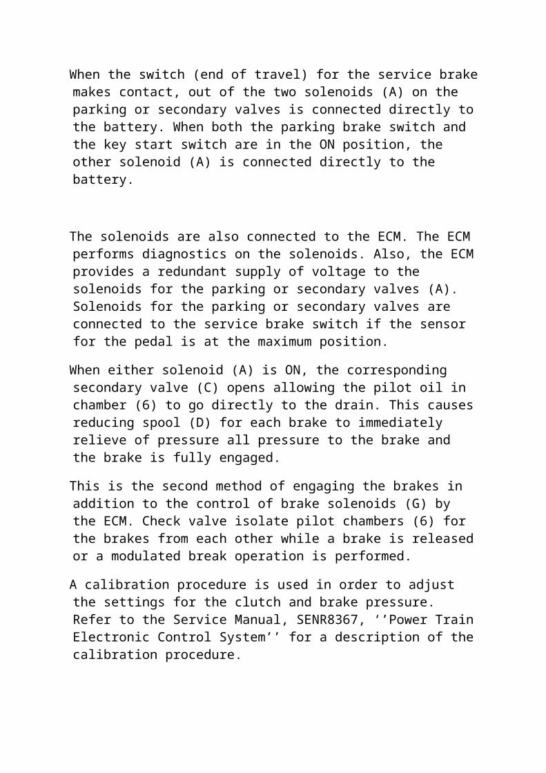
When the switch (end of travel) for the service brakemakes contact, out of the two solenoids (A) on the parking or secondary valves is connected directly tothe battery. When both the parking brake switch and the key start switch are in the ON position, the other solenoid (A) is connected directly to the battery.
The solenoids are also connected to the ECM. The ECM performs diagnostics on the solenoids. Also, the ECMprovides a redundant supply of voltage to the solenoids for the parking or secondary valves (A). Solenoids for the parking or secondary valves are connected to the service brake switch if the sensor for the pedal is at the maximum position.
When either solenoid (A) is ON, the corresponding secondary valve (C) opens allowing the pilot oil in chamber (6) to go directly to the drain. This causesreducing spool (D) for each brake to immediately relieve of pressure all pressure to the brake and the brake is fully engaged.
This is the second method of engaging the brakes in addition to the control of brake solenoids (G) by the ECM. Check valve isolate pilot chambers (6) for the brakes from each other while a brake is releasedor a modulated break operation is performed.
A calibration procedure is used in order to adjust the settings for the clutch and brake pressure. Refer to the Service Manual, SENR8367, ‘’Power TrainElectronic Control System’’ for a description of thecalibration procedure.

NOTE: The steering clutches and brakes will need to be recalibrated if any of the following items are replaced or serviced:
1.Steering and brake control valve
2.Solenoids
3.Steering clutch and the brake module.
4.ECM
GRADUAL RIGHT TURN
ILLUSTRATION 2
STEERING AND BRAKE CONTROL VALVE
(1). Circuit for clutch oil
(2). Clutch spool for right steering
(4). Right brake spool
(A). Secondary brake solenoids
(G). Proportional valves
(AA). Supply oil
(BB). Brake pressure oil
(CC). Left clutch oil
(EE). Pilot signal oil for the brake
(FF). Pilot signal oil for the clutch
(LL). Drain oil

CONTROL VALVE OPERATION FOR A GRADUAL RIGHT TURN
NOTE: The steering clutch and the brake are not engaged.
The control valve has proportional solenoid valves (G) which control the position of pressure reducing spools (4) in the control valve.
As the operator begins to pull the right steering control lever, the pulse width modulated sensors senda signal to the ECM. This signal is sent in order to decrease the current going to proportional solenoid valve (G) for the right clutch.
The decreased current causes a decrease in pilot oil pressure which causes reducing spool (4) to shift to the left. This shift exhausts the oil in the clutch oil pressure is lowered.
The current that goes to the solenoid for the proportional valve is dependent upon the position of the control lever. The solenoid sets the pilot oil pressure. The pressure in the clutch circuit is directly affected by the position of the control lever.
When the control lever is pulled back the clutch pressure is reduced. When you pull back the control lever further, the clutch pressure is reduced until the pressure 0 kPa (0 psi) and the clutch is released. The machine will then make a gradual right turn.
SHARP RIGHT TURN
ILLUSTRATION 3

STEERING AND BRAKE CONTROL VALVE
(4) Right brake spool
(A) Secondary brake solenoids
(G) Proportional valves
(AA) Supply oil
(BB) Brake pressure oil
(CC) Left clutch oil
(EE) Pilot signal oil for the brake
(FF) pilot signal oil for the clutch
(LL) Drain oil
CONTROL VALVE OPERATION FOR A GRADUAL RIGHT TURN
NOTE: The steering clutch and the brake are not engaged.
The control valve has proportional solenoid valves (G) which control the position of pressure reducing spools (4) in the control valve
As the operation begins to pull the right steering control lever, the pulse width modulated sensors senda signal to the ECM. This signal is sent in order to decrease the current going to proportional solenoid valve (G) for the right clutch.
The decreased current causes a decrease in pilot oil pressure which causes reducing spool (4) to shift to the left. This shifts exhausts the oil in the clutch circuit. When the oil is exhausted, the clutch oil pressure is lowered.

The current that goes to the solenoid for the proportional valve is dependent upon the position of the control lever. The solenoid sets the pilot oil pressure. The pressure in the clutch circuit is directly affected by the position of the control lever.
When the control lever is pulled back, the clutch pressure is reduced. When you pull back the control lever further, the clutch pressure is reduced until the pressure reaches 0 kPa (0 psi) and the clutch is released. The machine will then make a gradual right turn.
SHARP RIGHT TURN
ILLUSTRATION 3
STEERING AND BRAKE CONTROL VALVE
(4) Right brake spool
(A) Secondary brake solenoids
(G) Proportional valves
(AA) Supply oil
(BB) Brake pressure oil
(CC) Left clutch oil
(EE) Pilot signal oil for the brake
(FF) Pilot signal oil for the clutch
(LL) Drain oil

CONTROL VALVE OPERATION FOR A SHARP RIGHT TURN
NOTE: The steering clutch is not engaged. The brake is engaged.
The control valve has proportional solenoid valves (G) which control the position of pressure reducing spools (4) in the control valve. These spools adjust the clutch and brake pressure when the control leversare moved.
In order to make a sharp right turn, the operator pulls the steering control lever backward all the way. During the first movement of the control lever, the clutch pressure is modulated to 0 kPa (0 psi). This is the same pressure as a gradual right turn.
As the operator continues to pull the control lever backward, the pulse width modulated sensors send the signal to the ECM. This signal decreases the current to the right proportional solenoid (G) for the brake.This decreases pilot oil pressure which causes reducing spool (4) to shift to the left. This shift to the left exhausts oil in the right brake circuit which drops the brake pressure.
The current that goes to the proportional solenoid valve is determined by the position of the control lever. The proportional solenoid valve sets the pilotpressure. The pressure in the brake circuit is directly affected by the position of the control lever.
When you pull back the control lever further, the brake pressure is reduced until a maximum pressure of325 kPa (47 psi) is reached and the brake is fully engaged. This operation results in a sharp right turnof the machine. Residual oil pressure is maintained

on the brake in order to improve system response whenthe brake is released.
SERVICE BRAKE PEDAL OPERATION
ILLUSTRATION 4
STEERING AND BRAKE CONTROL VALVE
(4) Reducing spool
(5) Right brake oil circuit
(6) Reducing spool
(7) Left brake oil circuit
(A) Secondary brake solenoids
(G) Proportional solenoid valves
(AA) Supply oil
(CC) Clutch oil
(FF) Pilot signal oil for the clutch
(LL) Drain oil
BRAKE PEDAL OPERATION.
When the operator begins to push the service brake pedal toward the floor, the rotary sensor sends a signal to the electronic control module (ECM). This signal tells the ECM the position of the service brake pedal. The ECM then ramps down the current going to the proportional solenoids (G) relative to the position of the pedal.

As the current going to the proportional solenoids decreases, the pilot pressure which is controlled by the proportional solenoids also decreases. A drop in pilot pressure at the proportional solenoid creates apressure differential across reducing spools (4) and (6). This pressure differential causes the reducing spools to shift to the left.
This movement to the left allows the brake oil in chambers (5) and (7) to exhaust to drain.
When the service brake pedal is partly depressed, thepilot pressure will partially decrease. Only a portion of the brake oil will be exhausted. This willresult in a light operation of the brakes.
When the service brake pedal is pushed to the floor, the service brake switch (end of travel) closes. A +battery signal activates secondary brake solenoid (A). This ensures that the brakes can be applied evenif the ECM loses power.
When the service brake pedal is fully depressed. Pilot pressure will decrease to zero. All of the brake oil will be exhausted to the drain. This will give full braking action.
The other secondary brake solenoid is also energized by the ECM. This exhaust any remaining pilot pressureoil to the drain. The reduction in oil pressure causes reducing spools (4) and (6) to shift to the left. The movement of the spools to the left drains all brake oil from the chambers (3) and (7). This operation results in maximum brake capacity.
GENERAL INFORMATION (STEERING)

SMCS – 4300
ILLUSTRATION 1
------ Pilot oil lines
(1) Steering wheel
(2) Pilot control valve
(3) Left steering cylinder
(4) Right steering cylinder
(5) Orifice
(6) Screen
(7) Crossover relief valve
(8) Shuttle valve
(9) Check valves
(10) Steering control valve
(11) Check valves
(12) Shuttle valves
(13) Neutralizer valve
(14) Pressure reducing valve
(15) Backup relief valve
(16) Implement circuit
(17) Screen
(18) Pilot oil pump
(19) Steering pump

(20) Diverter valve
(21) Hydraulic oil tank
(22) Secondary steering pump
(23) Secondary steering relief valve
(24) Selector valve
(25) Pressure switch
Your machine may be equipped with command controlsteering. Machines that have command control steering will steer differently than other machines. The turning speed of the machine depends on the rotational position of the steering wheel. The machine will continue to articulate as the steering wheel is rotated. Whenthe steering wheel is allowed to return to the centre position, further articulation of the machine is prevented.
GRINDING MACHINE
- Grinding means to abrade, to wear away by friction.

- It refers to the removal of metal by rotating abrasive wheel. The wheel action is similar to a milling cutter.
- The cutting wheel is composed of many bonded grains together, each one acting as a miniature cutting point.
MULTI-CUTTING EDGE TOOL
- In grinding operation, the grinding wheel which is the cutter moves against the work piece.
- Abrasive grains which are the cutting tools or cutting edges are held by bonds.
- Various speeds are used depending on the type of jobs.
- The work piece also cuts the grinding wheel.
- The grinding wheel is made up of multi-point cutting tools in all directions.
- Any shape can be grinded using the grinding machine.
- Any material can be cut by grinding machine.
FUNCTION OF THE GRINDING WHEEL
- There are three functions which are basic to all grinding wheel operations.
. To generate size : This is toremove enough material to bring workpiece within the close tolerance of sizedesired.

. To generate surface : This is to produce good surface or luster on the workpiece.
. To remove stock : This is to remove stock for its own sake, tolerance andfinish being secondary if considered at all.
THE GRINDING WHEEL
. Al2O3 (Aluminium Oxide)Its trade name is ALUNDUM. It is tough, not easily fractured, used for grinding material of high tensilestrength. It is obtained naturally. It is used for the production of grinding wheels.. SiC (Silicon Carbide)Its trade name is CARBORUNDUM. It is harder than Al2O3 but not tough enough. It is used for grinding wheels of low tensile strength materials.. Diamond (Natural)It is the hardest of all the cutting tool materials.
BONDThe following five important materials are used as binders for grinding wheels.. Vitrified Bond (clay) It gives a wheel good strength as well as porosity toallow high stock removalIt is not affected by water, acids, oils or ordinary conditions (about 75% of grinding wheels are made of it).. Silicate Bond (glass)It releases abrasive grains more readily than vitrified bondsIt has greatest application in grinding edge tools where heat generated must be kept to a minimum.

. Shellac Bond (secretion of insects on trees)It is used to produce special types of grinding wheels.. Resinoid BondIt is a synthetic organic compound which allows wheels to remain cool and give a high stock removal rate at high speed..Rubber BondThis is used where good finish is a primary requirement. It is strong and tough enough to make extremely thin wheels.
TRUING AND DRESSING.TRUING: this is the process of restoring the shape and form of the grinding wheel, so that it will run true and produced perfectly round or flat work.Truing is to change, adjust and maintain the exact shape of the wheel is required and the surface inclination.DRESSING: It is an act of improving the cutting action of a grinding wheel. When the wheel is loaded with dust, dirt, etc, it is refered to as a dull wheel.The dressing tool improves the wheel by removing the outside layer of the dulled abrasive grains, dust, dirt or any other foreign material. Dressing does notinvolve adjustment of size, stability, etc of the wheel.
DRESSING TOOLS1.Dressing Star
The tool consists of pointed disks, loosely revolving on a pin and held to the wheel with a handle.
2.Abrasive sticks and wheels3.Diamond dressing tools

An industrial diamond is mounted in a matrix in aholder and usually is firmly fastened to the machine in some way so as to give a real truing action