non conventional cooling system with lpg - zenodo
TRANSCRIPT
1 Page 1-10 © MANTECH PUBLICATIONS 2020. All Rights Reserved
Journal of Thermal Engineering and Technology
Volume 5 Issue 1
Non Conventional Cooling System with LPG
Haware Mubarakmiya A. G*, Bhingade Akshay P.*
Lecturers*
Department of Mechanical Engineering
JSPMS’s BIT, Barshi
Corresponding Author’s email id: [email protected], [email protected]
DOI: 10.5281/zenodo.3782261
Abstract
A non-conventional cooling system uses LPG (Liquefied Petroleum Gas as
Refrigerant). Domestic refrigerator which containing chlorine or fluorine item
which is ban by international law due to ozone layer depletion and global
warming problem. This work enables to boost the calorific value of gas by
ensuring the vapor gas is going to burner. This project works on simple vapor
compression refrigeration cycle. The vapor compression refrigeration cycle
consists of compressor, condenser, capillary tube & evaporator. The
compressor whose function is to increase pressure and temperature of vapor
refrigerant and condenser is used for condensation of high temperature and
high pressure vapor. These cycles are replaced by LPG cylinder i.e. (LPG
cylinder has compressed & condensed refrigerant init).
The LPG cylinder work as compressor and condenser. The high pressure LPG
is passing through refrigeration circuit in which it passes through
expansion valve or capillary tube & loop of evaporator. Due to it the latent
heat of Liquefied Petroleum Gas gets converted from liquid to vapor which is
called latent heat of evaporation of LPG. The cooling effect is obtained by
using this latent heat of LPG in evaporator. Hence only vapor is supplied to
the burner.
Keywords: - LPG Cylinder, Capillary Tube, Evaporator, Digital
Thermometer, Burner.
2 Page 1-10 © MANTECH PUBLICATIONS 2020. All Rights Reserved
Journal of Thermal Engineering and Technology
Volume 5 Issue 1
INTRODUCTION
The non-conventional Refrigeration
System works on latent heat of
vaporization of liquefied petroleum gas.
This project gives output free of cost; it
requires only the refrigeration circuit for
getting cooling effect. The refrigeration
circuit in non-conventional refrigeration
system absorbs latent heat from liquefied
petroleum gas, due to the heat absorbed
liquefied petroleum gas gets converted to
vapor. The heat absorb by liquefied
petroleum gas is equal for latent heat of
evaporation of liquefied petroleum gas.
This project having creative idea which is
suitably commercially in various sectors
likes big restaurants, hotels and such
places where continuous burning of LPG
is required. Due to the introduction of
refrigeration circuit in between LPG
cylinder and burner there is marginally
improvement in calorific value than
conventional.
In normal refrigeration circuit use
refrigerant to get the refrigerating effect
for this to supply power to compressor for
this purpose but here inverted LPG gives
the cooling effect without any input. The
non-conventional refrigeration system
works on the principle same as the vapor
compression (VCC) refrigeration system.
Instead of compressor & condenser use
LPG cylinder which has pressure in
between 5-7 bar for getting cooling effect.
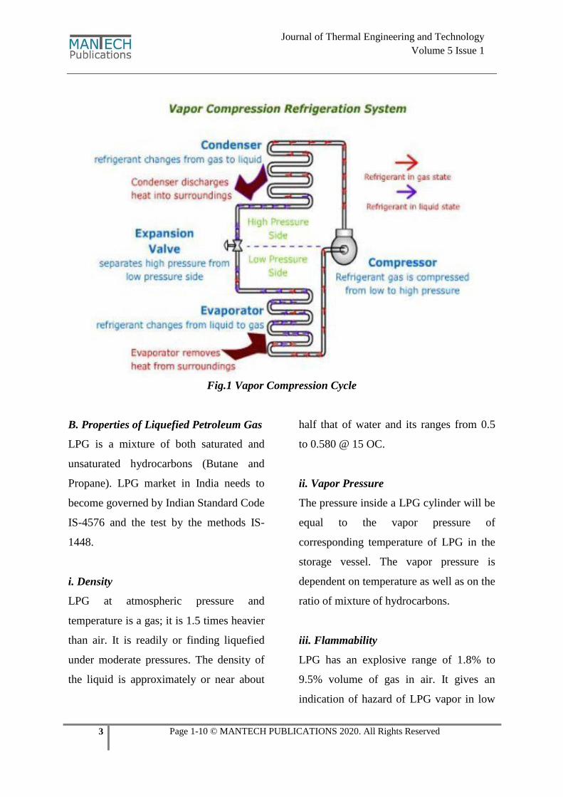
A. Operation of Vapor Compression
Cycle
Vapor compression cycle is an improved
type of air refrigeration cycle in this
refrigerant used as working substance. The
refrigerants generally used for this purpose
are R134a, R12, ammonia (NH3), carbon
dioxide (CO2) and sulphur- dioxide (SO2).
The refrigerant generally used, don’t leave
to the system, but it is circulated in the
system alternately condensing and
evaporating. In evaporating, the refrigerant
absorbs its latent heat from the used
solution which is for circulating it’s
around the cold chamber and condensing;
it gives out its latent heat to the circulating
water of the cooler.
The vapor compression cycle which is
used for all purpose of refrigeration. It is
used for all industrial purposes from a
small domestic refrigerator to a big air
conditioning plant.
3 Page 1-10 © MANTECH PUBLICATIONS 2020. All Rights Reserved
Journal of Thermal Engineering and Technology
Volume 5 Issue 1
Fig.1 Vapor Compression Cycle
B. Properties of Liquefied Petroleum Gas
LPG is a mixture of both saturated and
unsaturated hydrocarbons (Butane and
Propane). LPG market in India needs to
become governed by Indian Standard Code
IS-4576 and the test by the methods IS-
1448.
i. Density
LPG at atmospheric pressure and
temperature is a gas; it is 1.5 times heavier
than air. It is readily or finding liquefied
under moderate pressures. The density of
the liquid is approximately or near about
half that of water and its ranges from 0.5
to 0.580 @ 15 OC.
ii. Vapor Pressure
The pressure inside a LPG cylinder will be
equal to the vapor pressure of
corresponding temperature of LPG in the
storage vessel. The vapor pressure is
dependent on temperature as well as on the
ratio of mixture of hydrocarbons.
iii. Flammability
LPG has an explosive range of 1.8% to
9.5% volume of gas in air. It gives an
indication of hazard of LPG vapor in low
4 Page 1-10 © MANTECH PUBLICATIONS 2020. All Rights Reserved
Journal of Thermal Engineering and Technology
Volume 5 Issue 1
lying area in the eventuality of the leakage
or spillage.
iv. Combustion
The combustion of LPG increases the
volume of refrigerant in addition to the
generation of heat. LPG requires up to 50
times its own volume of air for complete
combustion.
v. Odor
LPG has only faint smell, and eventually,
it is necessary to add some odorant, so that
any leakage gas can easily be detected.
Ethyl Mercaptan is normally used as
stanching agent for this purpose.
vi. Color
LPG is colorless in case of both liquid and
vapor. During leakage the vaporization of
liquid cools the atmosphere and condenses
the water vapor in the form fog which may
make it possible to see an escape of LPG.
vii. Toxicity
LPG even though slightly toxic, it isn’t
poisonous in vapor phase, but suffocates
when in large concentrations due to the
fact that it displaces oxygen. In view of
this the vapor possess mild an aesthetic
properties.
C. Component of Non-Conventional
Refrigeration System
LPG Cylinder
Strainer (filter)
Capillary Tube
Regulator
Evaporator Box
Digital Thermometer
Pressure Gauge
Hose Tubing
Burner
FABRICATION STAGES
The various stages of fabrication of the
NCCS model as Follows:
Fabrication of frame.
Attachment of gas, pressure gauge,
thermometer, capillary tube,
burner.
Mounting of capillary tube & rigid
tube by brazing operation.
Brazing: - Brazing is a joining
process which is used to joining
two metals.
These two metals are joined by melting
filler metal. Melting point of filler metal
should be less than adjoining metal.
5 Page 1-10 © MANTECH PUBLICATIONS 2020. All Rights Reserved
Journal of Thermal Engineering and Technology
Volume 5 Issue 1
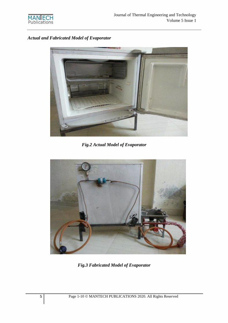
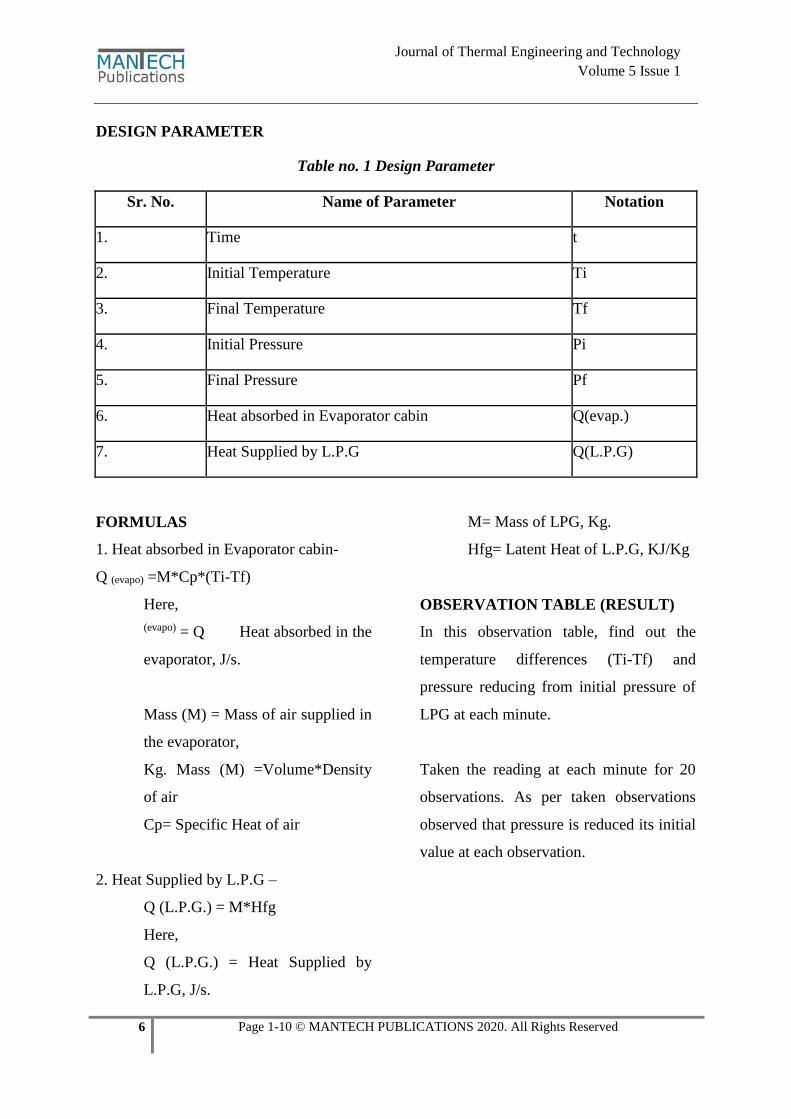
Actual and Fabricated Model of Evaporator
Fig.2 Actual Model of Evaporator
Fig.3 Fabricated Model of Evaporator
6 Page 1-10 © MANTECH PUBLICATIONS 2020. All Rights Reserved
Journal of Thermal Engineering and Technology
Volume 5 Issue 1
DESIGN PARAMETER
Table no. 1 Design Parameter
Sr. No. Name of Parameter Notation
1. Time t
2. Initial Temperature Ti
3. Final Temperature Tf
4. Initial Pressure Pi
5. Final Pressure Pf
6. Heat absorbed in Evaporator cabin Q(evap.)
7. Heat Supplied by L.P.G Q(L.P.G)
FORMULAS
1. Heat absorbed in Evaporator cabin-
Q (evapo) =M*Cp*(Ti-Tf)
Here,
(evapo) = Q Heat absorbed in the
evaporator, J/s.
Mass (M) = Mass of air supplied in
the evaporator,
Kg. Mass (M) =Volume*Density
of air
Cp= Specific Heat of air
2. Heat Supplied by L.P.G –
Q (L.P.G.) = M*Hfg
Here,
Q (L.P.G.) = Heat Supplied by
L.P.G, J/s.
M= Mass of LPG, Kg.
Hfg= Latent Heat of L.P.G, KJ/Kg
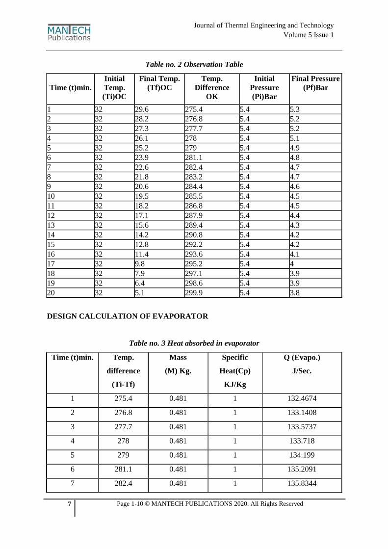
OBSERVATION TABLE (RESULT)
In this observation table, find out the
temperature differences (Ti-Tf) and
pressure reducing from initial pressure of
LPG at each minute.
Taken the reading at each minute for 20
observations. As per taken observations
observed that pressure is reduced its initial
value at each observation.
7 Page 1-10 © MANTECH PUBLICATIONS 2020. All Rights Reserved
Journal of Thermal Engineering and Technology
Volume 5 Issue 1
Table no. 2 Observation Table
Time (t)min.
Initial
Temp.
(Ti)OC
Final Temp.
(Tf)OC
Temp.
Difference
OK
Initial
Pressure
(Pi)Bar
Final Pressure
(Pf)Bar
1 32 29.6 275.4 5.4 5.3
2 32 28.2 276.8 5.4 5.2
3 32 27.3 277.7 5.4 5.2
4 32 26.1 278 5.4 5.1
5 32 25.2 279 5.4 4.9
6 32 23.9 281.1 5.4 4.8
7 32 22.6 282.4 5.4 4.7
8 32 21.8 283.2 5.4 4.7
9 32 20.6 284.4 5.4 4.6
10 32 19.5 285.5 5.4 4.5
11 32 18.2 286.8 5.4 4.5
12 32 17.1 287.9 5.4 4.4
13 32 15.6 289.4 5.4 4.3
14 32 14.2 290.8 5.4 4.2
15 32 12.8 292.2 5.4 4.2
16 32 11.4 293.6 5.4 4.1
17 32 9.8 295.2 5.4 4
18 32 7.9 297.1 5.4 3.9
19 32 6.4 298.6 5.4 3.9
20 32 5.1 299.9 5.4 3.8
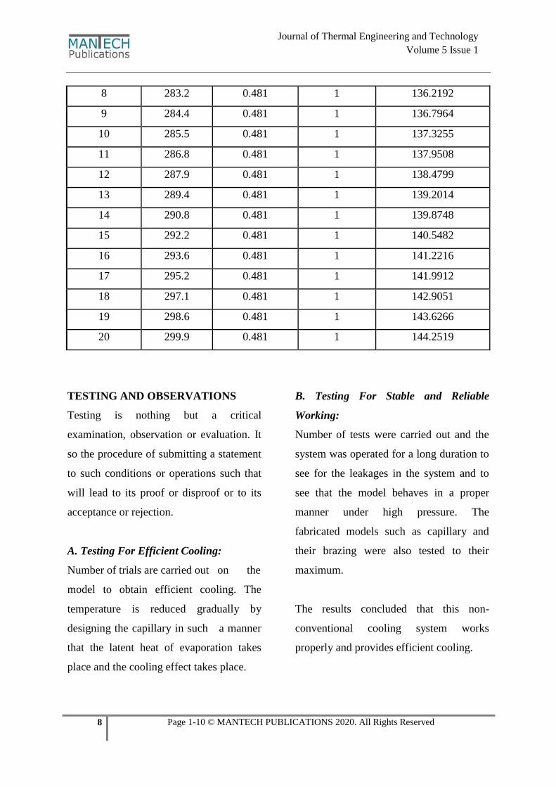
DESIGN CALCULATION OF EVAPORATOR
Table no. 3 Heat absorbed in evaporator
Time (t)min. Temp.
difference
(Ti-Tf)
Mass
(M) Kg.
Specific
Heat(Cp)
KJ/Kg
Q (Evapo.)
J/Sec.
1 275.4 0.481 1 132.4674
2 276.8 0.481 1 133.1408
3 277.7 0.481 1 133.5737
4 278 0.481 1 133.718
5 279 0.481 1 134.199
6 281.1 0.481 1 135.2091
7 282.4 0.481 1 135.8344
8 Page 1-10 © MANTECH PUBLICATIONS 2020. All Rights Reserved
Journal of Thermal Engineering and Technology
Volume 5 Issue 1
8 283.2 0.481 1 136.2192
9 284.4 0.481 1 136.7964
10 285.5 0.481 1 137.3255
11 286.8 0.481 1 137.9508
12 287.9 0.481 1 138.4799
13 289.4 0.481 1 139.2014
14 290.8 0.481 1 139.8748
15 292.2 0.481 1 140.5482
16 293.6 0.481 1 141.2216
17 295.2 0.481 1 141.9912
18 297.1 0.481 1 142.9051
19 298.6 0.481 1 143.6266
20 299.9 0.481 1 144.2519
TESTING AND OBSERVATIONS
Testing is nothing but a critical
examination, observation or evaluation. It
so the procedure of submitting a statement
to such conditions or operations such that
will lead to its proof or disproof or to its
acceptance or rejection.
A. Testing For Efficient Cooling:
Number of trials are carried out on the
model to obtain efficient cooling. The
temperature is reduced gradually by
designing the capillary in such a manner
that the latent heat of evaporation takes
place and the cooling effect takes place.
B. Testing For Stable and Reliable
Working:
Number of tests were carried out and the
system was operated for a long duration to
see for the leakages in the system and to
see that the model behaves in a proper
manner under high pressure. The
fabricated models such as capillary and
their brazing were also tested to their
maximum.
The results concluded that this non-
conventional cooling system works
properly and provides efficient cooling.
9 Page 1-10 © MANTECH PUBLICATIONS 2020. All Rights Reserved
Journal of Thermal Engineering and Technology
Volume 5 Issue 1
FUTURE SCOPE
India is facing an acute energy scarcity
which is hampering its industrial growth
and economic progress. Setting up of new
power plants is inevitably dependent on
import of highly volatile fossil fuels. Thus,
it is essential to tackle the energy crisis
through judicious utilization of abundant
the non- conventional energy resources,
such as biomass energy, solar energy,
wind energy and geothermal energy. Apart
from augmenting the energy supply of
renewable resources will help India in to
mitigate changing the climate. India is
heavily dependent on fossil fuels for its
energy needs.
Most of the power generation performed
by coal and mineral oil-based power plants
they are responsible to greenhouse gases
emission. The average per capita
consumption of energy in India is around
500 W; it is much lower than that of
developed countries like Japan, Europe
and USA etc. However, this figure is
expected to rise sharply due to high
economic growth and rapid
industrialization. Energy is a necessity and
sustainable non-conventional energy is a
vital link in industrialization and
development of India.
CONCLUSION
This paper concluded the use of one input
get two output. Input is LPG and gets
output as cooling effect up to 5 OC in
evaporator and gets the pure vapor gas to
burner due to this increasing the life and
efficiency of gas. In addition, non-
conventional energy has the potential to
create many employment opportunities at
all levels, especially in rural areas. An
emphasis on presenting the real picture of
massive non-conventional energy
potential, it would be possible to attract
foreign investments to herald a Green
Energy Revolution in India. So the world
has already made a beginning to bring
about the infrastructural changes in the
energy sector so as to be able to choose the
non-conventional energy development
trajectory.
REFERENCES
I. Ibrahim Husain Shah1 & Kundan
Gupta2, “Design of LPG
Refrigeration System and
Comparative Energy Analysis with
Domestic Refrigerator”, (IJESRT)
ISSN: 2277-9655, July 2014 PP:
206-213.
II. Shank K. Wang, Handbook of air
conditioning and refrigeration”
Edition.
10 Page 1-10 © MANTECH PUBLICATIONS 2020. All Rights Reserved
Journal of Thermal Engineering and Technology
Volume 5 Issue 1
III. Baskaran, P. Koshy Mathews,
International Journal of Scientific
and Research Publications”,
Volume 2, Issue 9, 1 ISSN 2250-
3153, September 2012.
IV. ASHRAE handbook1998.
V. C.P. ARORA, “Hand book of
Refrigeration and air
conditioning”, by page no.425.
Author’s Profile
Haware Mubarakmiya A. G
Lecturer at JSPMS’s BIT, Barshi
Mechanical Engineering Department
Mail Id- [email protected]
Cite this Article as
Haware Mubarakmiya A. G, Bhingade
Akshay P. (2020) “Non Conventional
Cooling System with LPG” Journal of
Thermal Engineering and Technology,
5 (1), 1- 10
http://doi.org/10.5281/zenodo.3782261