experimental apparatus for measurement of density of
TRANSCRIPT
EXPERIMENTAL APPARATUS FOR MEASUREMENT OF DENSITY OF SUPERCOOLED WATER AT HIGH PRESSURE
Jan HRUBÝ�, Jiří HYKL�, Pavel PEUKERT�, Bohuslav ŠMÍD�
Abstract: Thermodynamic behavior of supercooled water (metastable fluid water existing transiently below the equilibrium freezing point) at high pressures was subject to many recent theoretical studies. Some of them assume that a second critical point of water exists, related to two liquid phases of supercooled water: the low-density liquid and the high-density liquid. To test these theories, an original experimental cryogenic apparatus is being developed. The volume changes are measured optically in custom-treated fused-silica capillary tubes. The capillaries are placed in a metal vessel designed for pressures up to 200 MPa. The vessel is connected to a circulation thermostat enabling a rapid change of temperature to prevent freezing. A new high-vacuum device was developed for degassing of the ultrapure water sample and filling it into the measuring capillaries. The experiments will contribute to fundamental understanding of the anomalous behavior of water and to applications in meteorology, aerospace engineering, cryobiology etc.
�Institute of Thermomechanics AS CR, v.i.i. Dolejškova 5, Prague 8, Czech Republic [email protected]
1. INTRODUCTION
Liquid water can exist at temperature below the freezing point for transient periods of time. Probability of formation of an ice nucleus is proportional to the volume of the liquid and progressively increases with increasing subcooling. Therefore, deep subcoolings are achieved in small water quantities such as droplets, water in pores, or capillaries. Thermodynamic properties of water and steam in stable regions are known to a high accuracy. All existing data was carefully considered by the International Association for the Properties of Water and Steam (IAPWS) and a formulation of thermodynamic properties was developed in the form of a Helmholtz function [1,2]. An auxiliary formulation of the properties of liquid water at near-atmospheric conditions was developed recently [3,4]. The equation by Wagner and Pruß [1] also considered the region of metastable subcooled water. However, the only data existing at that time concerned density, isobaric heat capacity, and speed of sound of supercooled water at atmospheric pressure. In particular, the density of supercooled water at atmospheric pressure was experimentally studied by Zheleznyi [5,6], Rasmussen and MacKenzie [7], and Hare and Sorensen [8,9]. Other researchers investigated the properties of amorphous forms of water at low temperatures. They guessed the shape of the equationn of state between the amorphous ice and supercooled water, the so-called no-man’s land. Among the various scenarios reviewed by Mishima and Stanley [10], at present as the most probable appears that of existence of the second critical point, an
EPJ Web of Conferences 25, 01026 (2012) DOI: 10.1051/epjconf/20122501026 © Owned by the authors, published by EDP Sciences, 2012
This is an Open Access article distributed under the terms of the Creative Commons Attribution License 2.0, which permits unrestricted use, distribution, and reproduction in any medium, provided the original work is properly cited.
Article available at http://www.epj-conferences.org or http://dx.doi.org/10.1051/epjconf/20122501026
end point of the line of coexistence of two forms (thermodynamic phases) of liquid water – the low-density liquid (LDL) and the high-density liquid (HDL). This hypothesis explains in an elegant manner the various anomalies of water and provides a relation between the liquid water and the amorphous phases: the low-density amorphous ice (LDA) and the high-density amorphous ice (HDA). This hypothesis was supported by molecular simulations. To test it experimentally, it was necessary to perform measurements of density of supercooled water and high pressures. This is a very difficult task. In 2009, the present group started to develop a device to measure the density of supercooled water in the pressure range up to 200 MPa. In the meantime, measurements were published by Mishima [11] up to 400 MPa using emulsified water. However, due to the experimental technique, the accuracy of measurements by Mishima is estimated by us to lay between ±0.5% and ±1.0% in density. The goal of the present effort is achieving accuracy better than ±0.1% in density as needed for the development of accurate equations of state. The limitation to pressures below 200 MPa appears, in view of the data by Mishima, not critical, because the location of the second critical point was estimated as 50 MPa and 223 K.
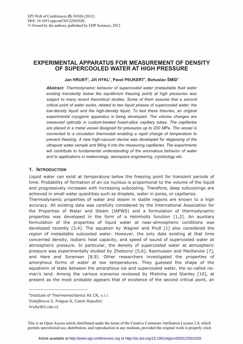
2. METHOD OF MEASUREMENT The main measuring principle is determination of the ratio of a density of supercooled water �L at temperature TL to density of stable liquid water �H at temperature TH at the same pressure. Water is enclosed in fused-silica capillaries with an internal diameter diameter of about 0.3 mm, sealed at one end. The position of the meniscus is measured with a camera equipped with a telecentric lens. In order that the measurement at high pressure is possible, the glass capillaries are enclosed in a stainless steel tube of outer diameter 6.35 mm. The menisci are located in an optical cell. The observed length of the capillaries is about 20 mm. The temperature of the stainless steel tube containing the capillaries is switched between the “low temperature” TL and the “high temperature” TH with help of a heat transfer fluid (ethanol) flowing along the outer surface of the tube. Because the optical cell is a massive part, its temperature cannot be changed quickly. Therefore, its temperature is maintained at the high temperature TH. In order to eliminate the influence of the transition between the two temperatures, a compensation method using two capillaries of different length was introduced. As shown in Figure 1, the
Figure 1: Scheme of measurement with two capillaries of different length for elimination of the effect of temperature transition
EPJ Web of Conferences
01026-p.2
temperature profile along each capillary consists of a part at the low temperature, transition part, and part at the high temperature. Consequently, the mass mi of liquid in each capillary i = 1,2, can be expressed as
� �a L t b m L Hi i i i i im V A V A z� � �� � � � , (1)
where Vai is the effective volume of the low-temperature part of the capillary, Vai is the effective volume of the high-temperature part of the capillary up to a mark, zLi is the distance from the mark to the water meniscus, sensed by the camera, Ami is the cross-section area of the capillary near the marker, Ati is the cross-section area of the capillary in the temperature transition region, and �� further called as “temperature defect”, expresses the deviation of the actual profile of the density from an idealized step-wise profile,
� � L H( ) ( )a a f
a e az dz z dz� � � � �
�
� � � � �� � . (2)
The absolute magnitude of the temperature defect cannot be determined with sufficient accuracy. However, it can be safely assumed that the temperature defects for both capillaries are the same. Then, upon dividing Eq.°(1) with the cross-sectional area in the transition region and subtracting the resulting expressions written for capillaries 1 and 2, we eliminate the temperature defect:
1 2 a1 a2 b1 b2 m1 m2L L1 L2 H
t1 t2 t1 t2 t1 t2 t1 t2
m m V V V V A Az zA A A A A A A A
� �� � � �
� � � � � � �� � � �� � � �
. (3)
We compare the measurement with different temperatures with a measurement at homogeneous temperature TH along the whole lengths of both capillaries. Then, the mass of liquid in each capillary is given as
� �a b m H Hi i i i im V V A z �� � � . (4)
For this measurement we express the difference
1 2 a1 a2 b1 b2 m1 m2H1 H2 H
t1 t2 t1 t2 t1 t2 t1 t2
m m V V V V A Az zA A A A A A A A
�� �
� � � � � � �� �� �
. (5)
Since the masses of liquid in the capillaries are conserved between the consecutive measurements, we can equate Eqs. (3) and (5) and express the searched density of supercooled water as
m1 t1 H1 L1 m2 t2 H2 L2L
( / )( ) ( / )( )1 HA A z z A A z z
L� �� � �
� �
, (6)
where we introduced the effective difference of lengths of the capillaries,
a1 a2
t1 t2
V VLA A
� � . (7)
Note that in Eq. (6) the terms containing volumes Vai cancelled. In order that the density can be determined, three calibration parameters are needed: the two ratios of cross sections, and the effective length difference. These parameters can be determined based
EFM11
01026-p.3
on metrological data for water density at atmospheric pressure between 0°C and 40°C [12]. In practice the diameter of the capillary is highly constant, so that the ratios of areas can be set unity. Then we are left only with the effective difference of the lengths of the capillaries, which can be determined either using the known densities at atmospheric pressure.
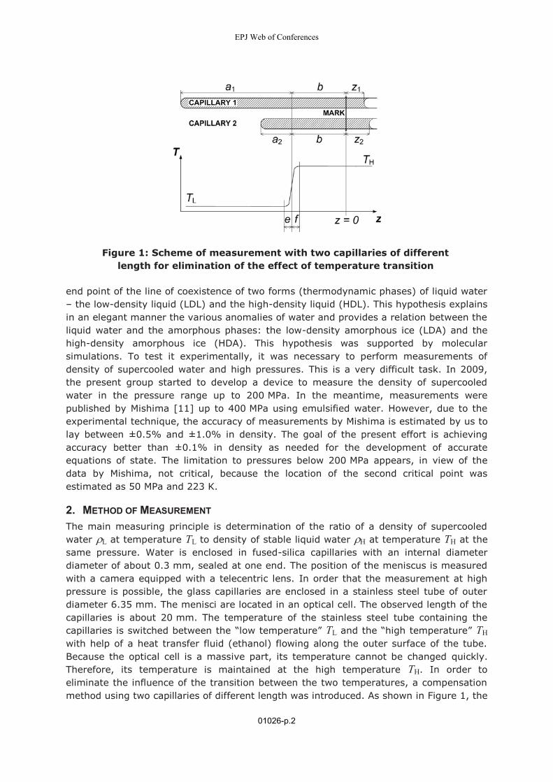
Figure 2: Scheme of the pressure circuit. Description is given in the text.
3. EXPERIMENTAL APPARATUS The pressure circuit of the experimental apparatus is shown in Figure 2. Two measuring capillaries 15 are enclosed in a stainless steel tube of outer diameter 6.35 mm, whose temperature is precisely tempered with circulating heat transfer fluid (ethanol) in heat exchanger 17. The menisci are located in optical cell 15. The optical cell is enclosed in safety pressure containment 18. The high pressure (up to 200 MPa) is generated in high-pressure compressor 3, supplied from gas cylinder 1 via a three-way valve 2. At the outlet of the compressor, safety rupture disc 4 is mounted. Via three-way pneumatic valve 5 the pressurized gas inters high-pressure reservoir 10. The function of the
EPJ Web of Conferences
01026-p.4
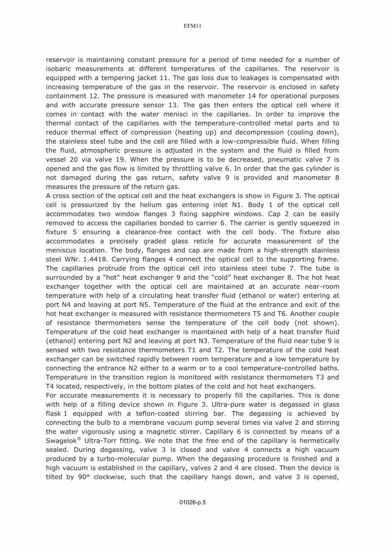
reservoir is maintaining constant pressure for a period of time needed for a number of isobaric measurements at different temperatures of the capillaries. The reservoir is equipped with a tempering jacket 11. The gas loss due to leakages is compensated with increasing temperature of the gas in the reservoir. The reservoir is enclosed in safety containment 12. The pressure is measured with manometer 14 for operational purposes and with accurate pressure sensor 13. The gas then enters the optical cell where it comes in contact with the water menisci in the capillaries. In order to improve the thermal contact of the capillaries with the temperature-controlled metal parts and to reduce thermal effect of compression (heating up) and decompression (cooling down), the stainless steel tube and the cell are filled with a low-compressible fluid. When filling the fluid, atmospheric pressure is adjusted in the system and the fluid is filled from vessel 20 via valve 19. When the pressure is to be decreased, pneumatic valve 7 is opened and the gas flow is limited by throttling valve 6. In order that the gas cylinder is not damaged during the gas return, safety valve 9 is provided and manometer 8 measures the pressure of the return gas. A cross section of the optical cell and the heat exchangers is show in Figure 3. The optical cell is pressurized by the helium gas entering inlet N1. Body 1 of the optical cell accommodates two window flanges 3 fixing sapphire windows. Cap 2 can be easily removed to access the capillaries bonded to carrier 6. The carrier is gently squeezed in fixture 5 ensuring a clearance-free contact with the cell body. The fixture also accommodates a precisely graded glass reticle for accurate measurement of the meniscus location. The body, flanges and cap are made from a high-strength stainless steel WNr. 1.4418. Carrying flanges 4 connect the optical cell to the supporting frame. The capillaries protrude from the optical cell into stainless steel tube 7. The tube is surrounded by a “hot” heat exchanger 9 and the “cold” heat exchanger 8. The hot heat exchanger together with the optical cell are maintained at an accurate near-room temperature with help of a circulating heat transfer fluid (ethanol or water) entering at port N4 and leaving at port N5. Temperature of the fluid at the entrance and exit of the hot heat exchanger is measured with resistance thermometers T5 and T6. Another couple of resistance thermometers sense the temperature of the cell body (not shown). Temperature of the cold heat exchanger is maintained with help of a heat transfer fluid (ethanol) entering port N2 and leaving at port N3. Temperature of the fluid near tube 9 is sensed with two resistance thermometers T1 and T2. The temperature of the cold heat exchanger can be switched rapidly between room temperature and a low temperature by connecting the entrance N2 either to a warm or to a cool temperature-controlled baths. Temperature in the transition region is monitored with resistance thermometers T3 and T4 located, respectively, in the bottom plates of the cold and hot heat exchangers. For accurate measurements it is necessary to properly fill the capillaries. This is done with help of a filling device shown in Figure 3. Ultra-pure water is degassed in glass flask 1 equipped with a teflon-coated stirring bar. The degassing is achieved by connecting the bulb to a membrane vacuum pump several times via valve 2 and stirring the water vigorously using a magnetic stirrer. Capillary 6 is connected by means of a Swagelok® Ultra-Torr fitting. We note that the free end of the capillary is hermetically sealed. During degassing, valve 3 is closed and valve 4 connects a high vacuum produced by a turbo-molecular pump. When the degassing procedure is finished and a high vacuum is established in the capillary, valves 2 and 4 are closed. Then the device is tilted by 90° clockwise, such that the capillary hangs down, and valve 3 is opened,
EFM11
01026-p.5
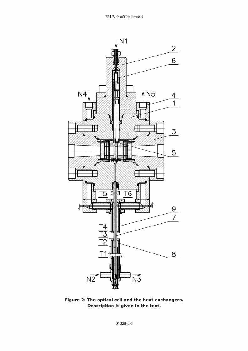
Figure 2: The optical cell and the heat exchangers.
Description is given in the text.
EPJ Web of Conferences
01026-p.6
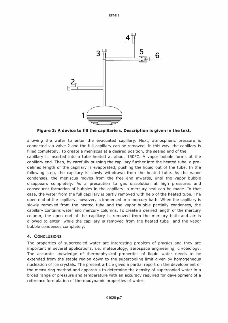
Figure 3: A device to fill the capillarie s. Description is given in the text.
allowing the water to enter the evacuated capillary. Next, atmospheric pressure is connected via valve 2 and the full capillary can be removed. In this way, the capillary is filled completely. To create a meniscus at a desired position, the sealed end of the capillary is inserted into a tube heated at about 150°C. A vapor bubble forms at the capillary end. Then, by carefully pushing the capillary further into the heated tube, a pre-defined length of the capillary is evaporated, pushing the liquid out of the tube. In the following step, the capillary is slowly withdrawn from the heated tube. As the vapor condenses, the meniscus moves from the free end inwards, until the vapor bubble disappears completely. As a precaution to gas dissolution at high pressures and consequent formation of bubbles in the capillary, a mercury seal can be made. In that case, the water from the full capillary is partly removed with help of the heated tube. The open end of the capillary, however, is immersed in a mercury bath. When the capillary is slowly removed from the heated tube and the vapor bubble partially condenses, the capillary contains water and mercury columns. To create a desired length of the mercury column, the open end of the capillary is removed from the mercury bath and air is allowed to enter while the capillary is removed from the heated tube and the vapor bubble condenses completely.
4. CONCLUSIONS The properties of supercooled water are interesting problem of physics and they are important in several applications, i.e. meteorology, aerospace engineering, cryobiology. The accurate knowledge of thermophysical properties of liquid water needs to be extended from the stable region down to the supercooling limit given by homogeneous nucleation of ice crystals. The present article gives a partial report on the development of the measuring method and apparatus to determine the density of supercooled water in a broad range of pressure and temperature with an accuracy required for development of a reference formulation of thermodynamic properties of water.
EFM11
01026-p.7
5. ACKNOWLEDGMENTS The authors gratefully acknowledge a support by grant No. IAA200760905 of the Grant Agency of the Academy of Sciences of the Czech Republic. Participation in IAPWS activities was supported by grant No. LA09011 of the Ministry of Education, Youth and Sports of the CR.
6. REFERENCES [1] Wagner W., Pruß A.: The IAPWS Formulation 1995 for the Thermodynamic
Properties of Ordinary Water Substance for General and Scientific Use. J. Phys. Chem. Ref. Data 31 (2002) 387—535.
[2] International Association for the Properties of Water and Steam, Release on the IAPWS Formulation 1995 for the Thermodynamic Properties of Ordinary Water Substance for General and Scientific Use, available at http://www.iapws.org (September 1996).
[3] Pátek J., Hrubý J., Klomfar J., Součková J., Harvey A.H.: Reference Correlations for Thermophysical Properties of Liquid Water at 0.1 MPa. Journal of Chemical and Physical Reference Data 38 (2009) 21—29.
[4] International Association for the Properties of Water and Steam, Supplementary Release on Properties of Liquid Water at 0.1 MPa, available at http://www.iapws.org (September 2008).
[5] Zheleznyi B.V.: The crystallization of supercooled water in capillaries. Russ. J. Phys. Chem. 42 (1968) 950—952.
[6] Zheleznyi B.V.: The density of supercooled water. Russ. J. Phys. Chem. 43 (1969) 1311—1311.
[7] Rasmussen D.H., MacKenzie A.P.: Clustering in supercooled water. J. Chem. Phys. 59 (1973) 5003—5013.
[8] Hare D.E., Sorensen C.M.: Densities of supercooled H2O and D2O in 25-micrometer glass capillaries. J. Chem. Phys. 84 (1986) 5085—5089.
[9] Hare D.E., Sorensen C.M.: The density of supercooled water. II. Bulk samples cooled to the homogeneous nucleation limit. J. Chem. Phys. 87, 4840—4845 (1987).
[10] Mishima O., Stanley H.E.: The relationship between liquid, supercooled, and glassy water. Nature 396 (1998) 329—335.
[11] Volume of supercooled water under pressure and the liquid-liquid critical point. 133 (2010) 144503-1—144503-6.
[12] Tanaka M., Girard G., Davis R., Peuto A., Bignell N.: Recommended table for the density of water between 0° C and 40° C based on recent experimental reports. Metrologia 38 (2001) 301—309.
EPJ Web of Conferences
01026-p.8