expected accuracy of tilt measurements on a novel hexapod-based digital zenith camera system: a...
TRANSCRIPT
Citation: Hirt, C., G. Papp, A. Pal, J. Benedek, and E. Szucs (2014), Expected accuracy of tilt measurements on a novel hexapod-based Digital Zenith Camera System – a Monte Carlo simulation study", Measurement Science Technology, 25, 085004 doi:10.1088/0957-0233/25/8/085004.
Expected accuracy of tilt measurements on a novel hexapod-based
Digital Zenith Camera System – a Monte-Carlo simulation study
Christian Hirt
Western Australian Centre for Geodesy & The Institute for Geoscience Research,
Curtin University, GPO Box U1987, Perth, WA 6845, Australia
Email: [email protected]
Currently at:
Institute for Astronomical and Physical and Geodesy & Institute for Advanced Study
Technische Universität München, Germany
Gábor Papp
Geodetic and Geophysical Institute
Research Centre for Astronomy and Earth Sciences, Hungarian Academy of Sciences,
Sopron H-9401, POB 5, Hungary
András Pál
Konkoly Observatory of the MTA Research Centre for Astronomy and Earth Sciences,
Konkoly Thege Miklós út 15-17, Budapest H-1117, Hungary
Judit Benedek
Geodetic and Geophysical Institute
Research Centre for Astronomy and Earth Sciences, Hungarian Academy of Sciences,
Sopron H-9401, POB 5, Hungary
Eszter Szucs
Geodetic and Geophysical Institute
Research Centre for Astronomy and Earth Sciences, Hungarian Academy of Sciences,
Sopron H-9401, POB 5, Hungary
Abstract
Digital Zenith Camera Systems (DZCS) are dedicated astronomical-geodetic measurement
systems for the observation of the direction of the plumb line. A DZCS key component is a
pair of tilt meters for the determination of the instrumental tilt with respect to the plumb line.
Highest accuracy (i.e., 0.1 arc-seconds or better) is achieved in practice through observation
with precision tilt meters in opposite faces (180° instrumental rotation), and application of
rigorous tilt reduction models. A novel concept proposes the development of a hexapod
(Stewart platform)-based DZCS. However, hexapod-based total rotations are limited to about
30° to 60° in azimuth (equivalent to 15° to 30° yaw rotation), which raises the question of
the impact of the rotation angle between the two faces on the accuracy of the tilt measurement.
The goal of the present study is the investigation of the expected accuracy of tilt
measurements to be carried out on future hexapod-based DZCS, with special focus placed on
the role of the limited rotation angle. A Monte-Carlo simulation study is carried out in order
to derive accuracy estimates for the tilt determination as a function of several input
parameters, and the results are validated against analytical error propagation. As main result
of the study, limitation of the instrumental rotation to 60° (30°) deteriorates the tilt accuracy
by a factor of about 2 (4) compared to a 180° rotation between the faces. Nonetheless, a tilt
accuracy at the 0.1 arc-second level is expected when the rotation is at least 45°, and 0.05 arc-
second (about 0.25 microradian) accurate tilt meters are deployed. As such, a hexapod-based
DZCS can be expected to allow sufficiently accurate determination of the instrumental tilt.
This provides supporting evidence for the feasibility of such a novel instrumentation. The
outcomes of our study are not only relevant to the field of DZCS, but also to all other types of
instruments where the instrumental tilt must be corrected. Examples include electronic
theodolites or total stations, gravity meters, and other hexapod-based telescopes.
Key words Hexapod, tilt measurement, tilt meter, Digital Zenith Camera System (DZCS),
Monte-Carlo simulation
1 Introduction
Zenith cameras are dedicated astronomical-geodetic telescopes for imaging of stars around the
zenith point in the sky. Such instruments are operated at field stations during night time
primarily to determine the direction of the vertical (plumb line). With a history of more than
120 years, zenith cameras were used in the past, e.g., for geographic positioning (e.g., Runge
1894), for observation of fluctuations in Earth’s orientation and rotation (e.g., McCarthy
1976) and gravity field studies (e.g., Torge 2001). Nowadays, zenith cameras – equipped
with digital imaging sensors (charge-coupled device, CCD) and other electronic sensors – are
deployed as digital zenith camera system (DZCS) for highly-accurate determination of the
gravity field (e.g., Hirt and Flury 2008, Hirt and Seeber 2008), or measurement of refraction
anomalies (Hirt 2006). For an overview of DZCS instrumental developments see, e.g., Bürki
et al. (2004), Hirt (2004), Kudrys (2007), Ogrizovic (2009), Hirt et al. (2010), Halicioglu et al.
(2012), Abele (2012), Hanada et al. (2012) and Wang et al. (2014).
A modern DZCS generally features (1) a CCD-telescope combination for star imaging, (2) a
Global Navigation Satellite System (GNSS) receiver for time tagging of the star images and
(3) a pair of accurate tilt meters (Hirt et al. 2010). The pair of tilt meters is being operated in
perpendicular orientation in order to (i) align the optical axis of the DZCS approximately with
the direction of the vertical (instrumental levelling), and to (ii) record any residual tilt of the
DZCS during the star imaging. This allows a subsequent mathematical correction of the
DZCS tilt. To eliminate instrumental zero offsets, DZCS measurements are carried out in two
opposite faces which usually differ by 180° in azimuth. For the rotation of the DZCS between
the two faces, some form of rotational unit (bearing, turntable, with or without motorization)
is traditionally used, and a tripod with three actuators or adjustable screws is deployed in most
instruments for levelling of the telescope (e.g., Bürki et al. 2004, Hirt et al. 2010).
A novel concept for DZCS instrumental levelling and rotation between the two-face
measurements was recently developed and presented at the Geodetic and Geophysical
Institute (GGI, Sopron) in collaboration with the Institute for Astronomy (Budapest), both
members of the Research Centre of Astronomy and Earth Sciences of the Hungarian
Academy of Sciences. In this concept, both the rotational unit and the tripod of traditional
zenith camera systems are replaced by a hexapod. Hexapods or Stewart-type platforms
(Stewart 1965) are platforms with three pairs of actuators (e.g., electromechanical or
hydraulic) offering six degrees of freedom in movement. They are routinely used in several
industrial applications, ranging from flight simulators to medical surgery. While the use of
hexapod platforms is not new in observational astronomy (e.g., Chini 2000, Koch et al. 2009,
Pál et al. 2013, Csépány et al. 2014, Vida et al. 2014), its use in geodetic-astronomical
applications and incorporation into DZCS has not yet been proposed nor investigated.
In the concept of a hexapod-based DZCS, the CCD sensor/telescope and tilt meters will be
mounted as ‘payload’ on top of the hexapod platform which – in our case – will be based on
six identical electromechanical actuators. Allowing versatile motion and micrometer-precise
positioning by length variation of the actuators, a hexapod-based DZCS may offer some
interesting potential advantages over “conventional” DZCS. For instance, as a benefit of a
hexapod-based DZCS, there will be one unified system deployed for all rotation and tilting of
the system rather than a combination of two systems (motorized tripod and rotational unit).
Given the high dynamic of hexapod platform positioning, a gain in speed for a DZCS two-
face measurement could be possible. As a further potential benefit, star tracking will become
possible over short time intervals, enabling more accurate imaging in general and increasing
the star count (capturing of fainter stars) in particular. By way of background, DZCS are
normally operated as non-tracking instruments where stars are imaged as trails due to Earth’s
rotation. However, while a possible operation of a hexapod-based DZCS in tracking mode
may improve the astrometric imaging, accurate tilt measurements may become more
demanding, e.g,. due to accelerations that superimpose the actual tilt signal and have to be
removed through filtering.
Different to a rotational unit that allows arbitrary rotation of the DZCS sensors, a hexapod is
not capable of executing 180°-rotations. Instead, the maximum possible azimuthal rotation
angle between the two faces is – depending on the hexapod design – limited to a range
between about 30° to 60° which is equivalent to 15° to 30° in yaw rotation. Thus, the
geometry of the two-face measurement with hexapods will be substantially different to a
conventional DZCS measurement in opposite faces (i.e., 180°). This immediately raises the
question of the impact of the rotation angle between the two faces on the accuracy of the tilt
measurement.
The goal of the present study is the investigation of the expected accuracy of tilt
measurements to be carried out on future hexapod-based DZCS, with special focus placed on
the role of the limited rotation angle. The study is organised as follows. Section 2 briefly
reviews our mathematical model for the accurate computation of the DZCS tilt correction
from tilt measurements in two faces. Section 3 then describes and applies a Monte-Carlo-type
simulation in order to derive accuracy estimates for the tilt correction as a function of several
parameters, among them the rotation angle between the two faces. This will a.) quantify the
expected loss in tilt measurement accuracy when compared to the assumed-to-be-ideal 180°
rotation, and b.) clarify if tilt measurements on hexapod-based DZCS can be expected to be
sufficiently accurate at all (say few tenths of arc-seconds or better) for state-of-the-art DZCS
field operation. Section 4 discusses the findings in view of the future construction of hexapod-
based DZCS and draws some conclusions.
The relevance of the findings of this study is not limited to the discipline of geodetic
astronomy and astronomic-geodetic instrumentation such as DZCS. The relevance may be
given also in view of all other types of instruments where the instrumental tilt must be
corrected. Examples include but are not limited to instruments for angle measurements such
as electronic theodolites or total stations, but also gravity meters (see, e.g., Torge 2001 for a
description of these instruments). However, the models and investigations presented in this
study may also prove useful in observational astronomy, where hexapod-based telescopes are
being increasingly used (e.g., Koch et al. 2009; Pál et al. 2013), and highly-accurate (say few
tenths of arc-seconds or better) tilt measurements appear not yet to be routinely applied.
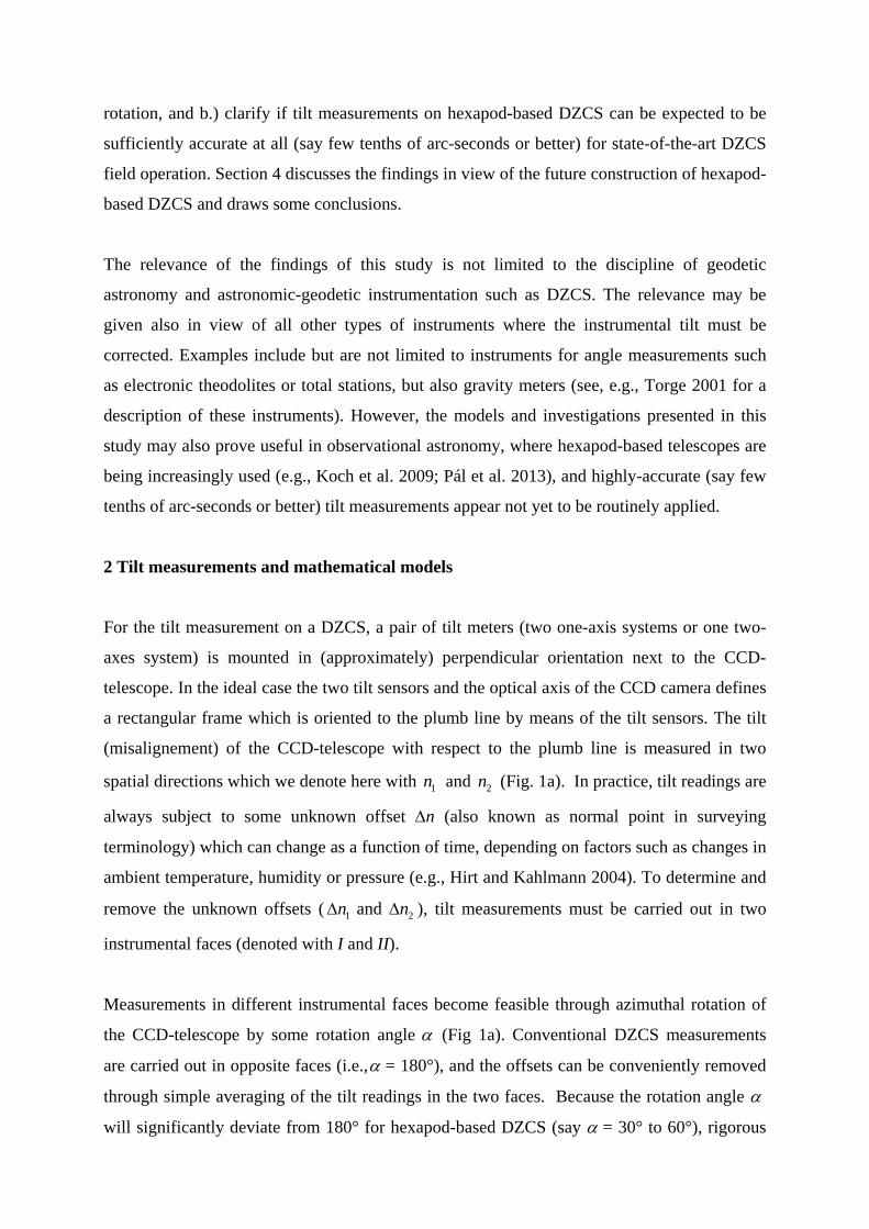
2 Tilt measurements and mathematical models
For the tilt measurement on a DZCS, a pair of tilt meters (two one-axis systems or one two-
axes system) is mounted in (approximately) perpendicular orientation next to the CCD-
telescope. In the ideal case the two tilt sensors and the optical axis of the CCD camera defines
a rectangular frame which is oriented to the plumb line by means of the tilt sensors. The tilt
(misalignement) of the CCD-telescope with respect to the plumb line is measured in two
spatial directions which we denote here with 1n and 2n (Fig. 1a). In practice, tilt readings are
always subject to some unknown offset n (also known as normal point in surveying
terminology) which can change as a function of time, depending on factors such as changes in
ambient temperature, humidity or pressure (e.g., Hirt and Kahlmann 2004). To determine and
remove the unknown offsets ( 1n and 2n ), tilt measurements must be carried out in two
instrumental faces (denoted with I and II).
Measurements in different instrumental faces become feasible through azimuthal rotation of
the CCD-telescope by some rotation angle (Fig 1a). Conventional DZCS measurements
are carried out in opposite faces (i.e., = 180°), and the offsets can be conveniently removed
through simple averaging of the tilt readings in the two faces. Because the rotation angle
will significantly deviate from 180° for hexapod-based DZCS (say = 30° to 60°), rigorous
mathematical models (Hirt 2008) are used here that account for in the reduction of the tilt
measurements. Based on practical experiences, we assume that the tilt meters cannot be
mounted exactly in perpendicular orientation. The shearing parameter is therefore
introduced to account for any misalignment of the two sensors from a 90° angular difference
between the two measurement axes (Fig. 1a). Typically, the shearing is close to 90°, e.g.,
89.4°, which is why power series expansions could be used where trigonometric functions of
appear in the sequel.
Figure 1. Panel a: Observation space for two-axes tilt measurements on a rotating platform.
Black: measurement axes in face I, red: measurement axes in face II (situation after rotation
by angle . In the observation space, the two axes are assumed to be sheared by angle .
Panel b: Solution space with exactly perpendicular axes. Note that the direction of the first
axis of the system 1n in face I is identical in both panels.
In the general case of tilt measurement on a DZCS, a set of two tilt readings ( 1In , 2
In ) is thus
taken in face I, and another set in face II (tilt readings 1IIn , 2
IIn ), cf. Fig 1a. The four
observations form the observation vector in the observation space

l =
1
2
1
2
I
I
II
II
n
n
n
n
(1)
which is the input for the computation of the unknown CCD-telescope tilt ( 1*n , 2*n ) – also
denoted here as tilt correction – and the unknown sensor offsets ( 1n , 2n ). The tilt
corrections ( 1*n , 2*n ) are free from the sensor offsets and refer to the orthogonal coordinate
system shown in Fig. 1b. The two spatial directions in the solution space (Fig. 1b) are
rigorously perpendicular (the shearing is removed), with the measurement axis of the first
direction ( 1n ) being identical in Figs. 1a and 1b. The vector of unknowns reads:
x =
1*
2*
1
2
n
n
n
n
(2)
The observations l and unknowns x are connected via the design matrix A which is set up as
a function of the rotation angle and the shearing between the measurement axes (Hirt
2008):
A = 1 0 1 0
cos sin 0 1
cos sin 1 0
cos( ) sin( ) 0 1
(3)
The design matrix connects observations and unknowns linearly
l Ax , (4)
allowing calculation of the vector of unknowns x via left-multiplication with the inverse
design matrix:
-1x = A l (5)
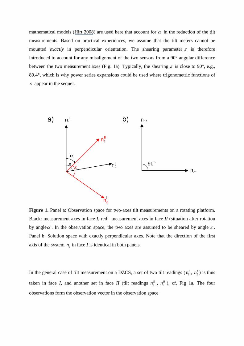
It is clear that the design matrix A becomes singular and Eq. 5 cannot be solved for the
unknowns if there is no rotation ( =0°) between the two faces (compare the first and third
row in Eq. 3). The design matrix becomes more stable as the rotation angle increases, with
optimum conditions assumed for the opposite-faces situation ( =180°). If tilt was measured
in more than two instrumental faces (e.g., each differing by 120°) in azimuth, the model
would be over-determined, requiring e.g., least-squares or other adjustment techniques (e.g.,
Moritz 1980). Because DZCS measurements in general and tilt measurements in particular are
usually conducted in the two faces, the over-determined case is not further dealt with in this
paper.
In practical applications, numerical estimates for the rotation angle are obtained as
difference of the astronomical azimuths of the CCD star images in face I and II. In case a
rotation unit (e.g., bearing) is deployed in the DZCS, an angle sensor might be alternatively
installed and used to provide information on . For the hexapod-based DZCS (without
bearing), the rotation angle could be worked out as a function of the length variation of the
six actuators between the two faces and the hexapod’s constructive constants (e.g., leg
separation), cf. Conti et al. (1998).
Numerical values for the shearing parameter are determined with the so-called celestial
calibration procedure whereby tilt measurements are compared against angles from star
images. To increase the sensitivity for the determination of , the DZCS is deliberately tilted
in all sky directions by about 100-120“ with respect to the plumb line (see Hirt 2004, Hirt et
al., 2010 for details). In the future, this procedure might be augmented (or replaced) by a
hexapod-based in-situ-calibration of the tilt sensors. Comparison of tilt values derived from
measured leg lengths with measured tilt values in a least-squares sense should be capable of
providing accurate estimates for the shearing , and also of the tilt sensor’s scale factors.
3 Monte-Carlo (MC) simulation
3.1 Idea and scheme
The Monte-Carlo (MC) simulation (e.g., Metropolis and Ulam 1949, Rubinstein and Kroese
2007) is a statistical simulation method which can be used to study the behaviour of

mathematical models or physical systems. The basic idea is the generation of sequences of
random input values, which are propagated through some formalism (here the mathematical
model for tilt measurements, Section 2). This yields output sequences of a certain statistical
distribution, which is then interpreted and further analysed, e.g., in terms of standard
deviations. As an advantage of the MC technique over classical numerical or analytical error
propagation techniques, many different scenarios can be easily investigated with the MC
simulation. The MC technique is chosen in the sequel as the most versatile statistical
simulation tool to propagate uncertainties for all quantities involved through the tilt reduction
model without simplifications. The robustness of results is ensured through choosing
sufficiently large sample sizes (e.g., 1000 repetitions in each simulation). For validation
purposes, analytical error propagation is applied (albeit with some simplifications) in
Appendix A, providing a valuable mutual check on the outcomes of the MC simulation.
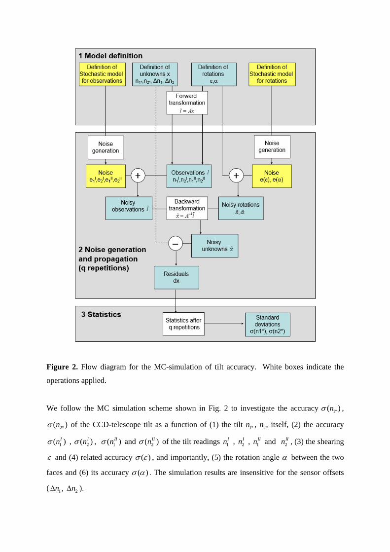
Figure 2. Flow diagram for the MC-simulation of tilt accuracy. White boxes indicate the
operations applied.
We follow the MC simulation scheme shown in Fig. 2 to investigate the accuracy 1*( )n ,
2*( )n of the CCD-telescope tilt as a function of (1) the tilt 1*n , 2*n itself, (2) the accuracy
1( )In , 2( )In , 1( )IIn and 2( )IIn of the tilt readings 1In , 2
In , 1IIn and 2
IIn , (3) the shearing
and (4) related accuracy ( ) , and importantly, (5) the rotation angle between the two
faces and (6) its accuracy ( ) . The simulation results are insensitive for the sensor offsets
( 1n , 2n ).
The accuracy simulation starts by assigning numerical values to the CCD-telescope tilt ( 1*n ,
2*n ), the sensor offsets ( 1n , 2n ), the shearing and rotation angle , before applying the
forward transformation (Eq. 4) to obtain the tilt meter readings ( 1In , 2
In , 1IIn , 2
IIn ) the two
sensors would measure if observation errors were absent. Regarding the numerical values, we
make the following choices:
The telescope tilt ( 1*n , 2*n ) with respect to the plumb line is generally kept below
10“ (arc seconds) in DZCS field applications. However, the telescope tilt can be
substantially larger, at the level of 100“ when the DZCS is celestially calibrated. Both
scenarios are simulated.
The tilt values ( 1*n , 2*n ) do not depend on the sensor offsets ( 1n , 2n ). Given the
simulated tilt accuracy is insensitive for ( 1n , 2n ), we choose arbitrary numerical
values of 1n = -5“ and 2n = +2“.
The shearing is generally close to 90°. Here we chose a value of 89.4°, which reflect
results from DZCS calibrations (Hirt 2004).
The rotation angle is tested over a range from 1° to 180°, which covers the expected
range for hexapod-based rotations (30° to 60°), while giving a complete picture of the
role of on the tilt accuracy.
In the next step, the stochastic models are defined for the observations l (Eq. 1) and for the
rotations , . We assume Gaussian noise distribution for all six quantities.
From practical experiences with high-resolution tilt meters, an observational accuracy
of 0.04-0.05“ can be reached in field applications (Hirt and Kahlmann, 2004, Hirt et
al., 2010). A value of 0.05“ is assigned to the noise generator that produces sequences
of random errors e = ( 1Ie , 2
Ie , 1IIe , 2
IIe ) which follow the Gaussian distribution with
the specified observational accuracy (Fig. 2). The vector of noisy observations l is
then obtained through addition of random errors e to the error-free tilt meter readings l
(cf. Fig. 2). As noise generator, Matlab’s randn-function is used.
In a similar manner, Gaussian random noise is generated and added to the shearing
and rotation angle , yielding noisy values and . The shearing is assumed to
be known with a standard deviation ( ) = 0.05°, and the rotation angle with a
standard deviation ( ) = 0.02° (values from Hirt 2004).
We note that in the parameters and are determined via astronomical measurement
procedures (rotation angle as difference between the astronomical azimuths of the CCD
sensor in both faces, shearing via the celestial calibration). A further increase in accuracy may
become possible through the development of a hexapod-based calibration procedure ( ), and
the determination of the rotation angle from the actual hexapod leg lengths.
As central step of the MC simulation, the backward-transformation (Eq. 5) is applied to
calculate noisy estimates for the telescope tilt ( 1*n , 2*n ) from l , and . This step
“propagates” the generated noise from the observation space (vector l) into the solution space
(vector x). The noisy telescope tilt ( 1*n , 2*n ) is then compared with the initial error-free values
( 1*n , 2*n ), yielding residuals
1* 1* 1*
2* 2* 2*
n n n
n n n
. (6)
The described procedure is repeated q times (here: q = 1000, which was found to give
statistically stable results from comparisons with other q-values, e.g., 100), giving sequences
of residuals which are used to calculate standard deviations for the tilt corrections ( *1n , *
2n )
21*
1*
( )( )
nn
q
(7)
22*
2*
( )( )
nn
q
.
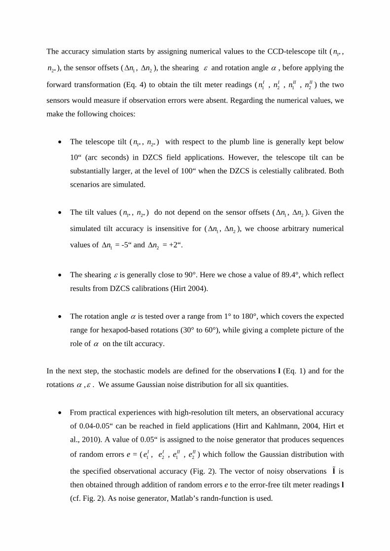
Exemplary histograms of the generated noise for the tilt observations l and rotations , are
shown in Fig. 3a – c, and histograms for the derived telescope tilt ( 1*n , 2*n ) in Fig. 3d. The
data shown in Fig 3d is used to calculate the standard deviations 1*( )n , 2*( )n for further
analysis.
Figure 3. Histograms of sample data from the MC-simulation for =60°. Panels a – b:
histograms of the noise for the tilt measurements (in arc-seconds), panel c: histograms of the
noise for the shearing and rotation angle , panel d: histograms of noisy telescope tilt ( 1*n ,
2*n ).
3.2 Results
Figure 4 shows the Monte-Carlo simulated standard deviations 1*( )n , 2*( )n for the tilt
corrections ( 1*n , 2*n ) as a function of the rotation angle . The accuracies for both
components of the tilt corrections are practically identical, and both deteriorate as the rotation
angle becomes smaller. The deterioration of the standard deviations 1*( )n as a function
of the rotation angle can be well modelled through a best-fitting (in a least-squares sense)
analytical function
1( )fitn = 0.0353“ 1sin 0.5
1*( )n 11sin 0.5
2 (8)
which has been intuitively found based on the MC-results. The best-fitting analytical function
is also shown in Fig. 4 (note that a very similar fit is obtained for 2*( )n ). With some
simplifications of the tilt model (Eqs. 3-5), the Eq. (8) can also be derived analytically (see
appendix A).
From Fig. 4, the accuracy 1*( )n , 2*( )n for the tilt corrections is about 0.036“ when the tilt
readings are taken in opposite faces with an observational accuracy of 1( )In = 2( )In =
1( )IIn = 2( )IIn = 0.05“. This corresponds to a gain in accuracy by factor of about 2 ,
which is plausible given that the two components ( 1*n , 2*n ) of the tilt corrections are based
on four observations l = ( 1In , 2
In , 1IIn , 2
IIn ).
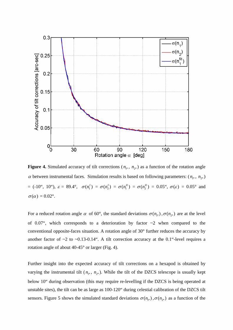
Figure 4. Simulated accuracy of tilt corrections ( 1*n , 2*n ) as a function of the rotation angle
between instrumental faces. Simulation results is based on following parameters: ( 1*n , 2*n )
= (-10“, 10“), = 89.4°, 1( )In = 2( )In = 1( )IIn = 2( )IIn = 0.05“, ( ) = 0.05° and
( ) = 0.02°.
For a reduced rotation angle of 60°, the standard deviations 1*( )n , 2*( )n are at the level
of 0.07“, which corresponds to a deterioration by factor ~2 when compared to the
conventional opposite-faces situation. A rotation angle of 30° further reduces the accuracy by
another factor of ~2 to ~0.13-0.14“. A tilt correction accuracy at the 0.1“-level requires a
rotation angle of about 40-45° or larger (Fig. 4).
Further insight into the expected accuracy of tilt corrections on a hexapod is obtained by
varying the instrumental tilt ( 1*n , 2*n ). While the tilt of the DZCS telescope is usually kept
below 10“ during observation (this may require re-levelling if the DZCS is being operated at
unstable sites), the tilt can be as large as 100-120“ during celestial calibration of the DZCS tilt
sensors. Figure 5 shows the simulated standard deviations 1*( )n , 2*( )n as a function of the
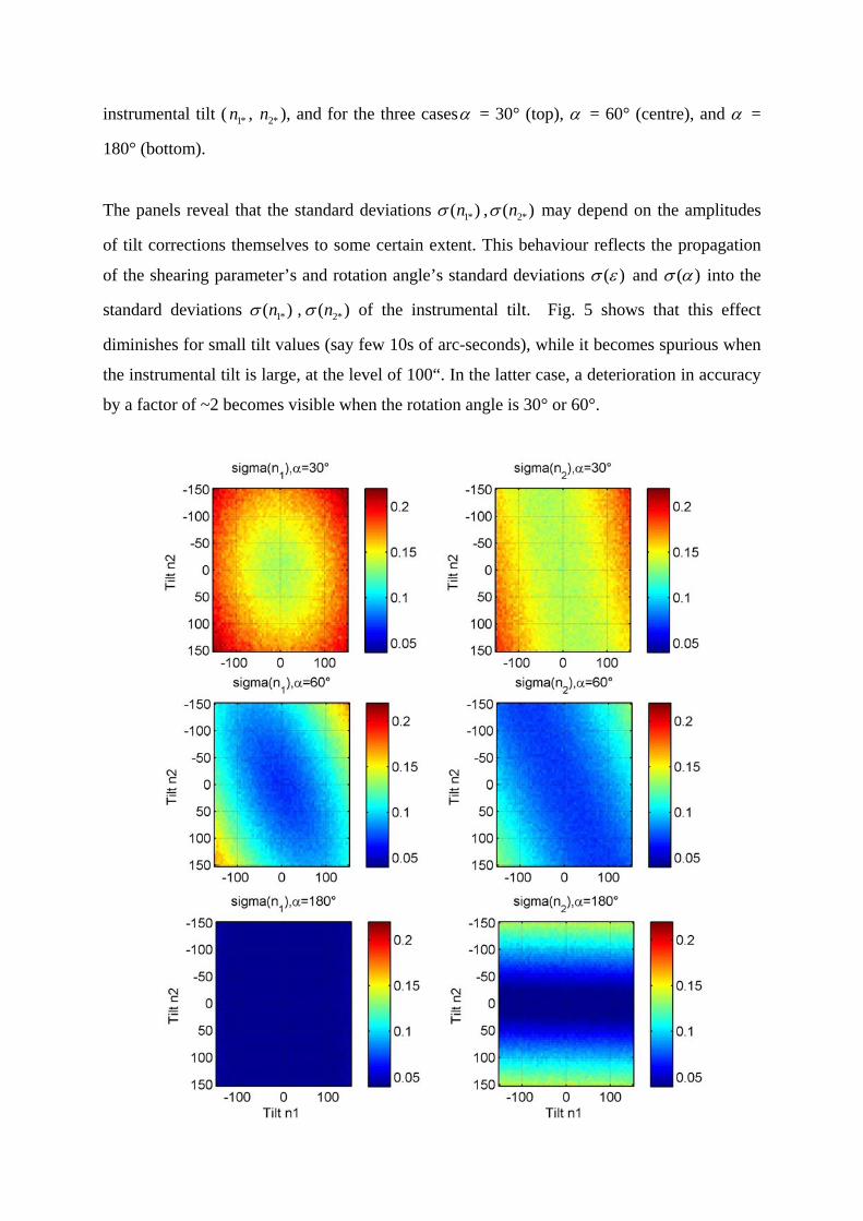
instrumental tilt ( 1*n , 2*n ), and for the three cases = 30° (top), = 60° (centre), and =
180° (bottom).
The panels reveal that the standard deviations 1*( )n , 2*( )n may depend on the amplitudes
of tilt corrections themselves to some certain extent. This behaviour reflects the propagation
of the shearing parameter’s and rotation angle’s standard deviations ( ) and ( ) into the
standard deviations 1*( )n , 2*( )n of the instrumental tilt. Fig. 5 shows that this effect
diminishes for small tilt values (say few 10s of arc-seconds), while it becomes spurious when
the instrumental tilt is large, at the level of 100“. In the latter case, a deterioration in accuracy
by a factor of ~2 becomes visible when the rotation angle is 30° or 60°.
Figure 5. Simulated accuracy of tilt corrections ( 1*n , 2*n ) as a function of the instrumental tilt
1*n , 2*n . Top: Rotation angle = 30°, Centre: rotation angle = 60°, Bottom: rotation angle =
180°, left column: 1*( )n , right column: 2*( )n . Simulation results are based on following
parameters: = 89.4°, 1( )In = 2( )In = 1( )IIn = 2( )IIn = 0.05“, ( ) = 0.05° and ( )
= 0.02°. All units in arc-seconds.
By way of comparison, the conventional case ( = 180°) shows that the standard deviation
1*( )n is practically independent from the instrumental tilt ( 1*n , 2*n ) over the whole range of
tilt values shown. Different to this, 2*( )n is independent from 1*n , but does depend on 2*n ,
with a decrease in accuracy by factor 2-3 visible for 2*n - values at the level of 100“. This is
related to the uncertainty of the shearing parameter ( ) which propagates into 2*n (but not
1*n ) when observations are taken in opposite faces. Irrespective of the rotation angle
investigated, the standard deviations are found to be invariant of the instrumental tilt if the
DZCS telescope is well levelled (say better than 10“).
4 Discussion and conclusions
Other than conventional DZCS, the proposed hexapod-based DZCS is not capable of
observing in opposite instrumental faces. Instead, the rotation angle of hexapod-based DZCS
is limited to about 30-60°. A Monte-Carlo simulation study was performed to investigate the
achievable accuracy for tilt corrections when the rotation angle is less than 180°. Statistical
analysis of the tilt correction’s accuracy as a function of the rotation angle revealed a loss in
accuracy by factor of ~2 for 60°-rotation, and a factor of ~4 for 30°-rotation in comparison to
the conventional 180° rotation between opposite instrumental faces. This corresponds to a
decrease in accuracy from about 0.03-0.04“ (rotation angle of 180°) to 0.07“ (rotation angle
of 60°). For today’s high-precision DZCS observations, it is reasonable to require a tilt
correction accuracy at the 0.1“-level or better. Our simulation shows that this requirement can
be met with hexapod-based DZCS if the rotation angle is at least 40-45°, and ~0.05“-accurate
tilt meters are deployed.
Further to this, the MC-simulation study demonstrates that there is no loss in accuracy at all
for rotation angles ranging between ~150° to 180° compared to the opposite-faces situation.
Thus, when using platforms with bearings or turntables, exact 180°-rotations between the
instrumental faces are not required for optimum accuracies as long as the rotation angle is
known with few 0.01° accuracy and taken into account in the reduction of the tilt
measurements (Section 2).
As a general conclusion of our study, a hexapod-based DZCS can be expected to be a suitable
platform for accurate tilt measurements. While the accuracy for the instrumental tilt
corrections will be worse in comparison to conventional opposite-face DZCS measurements,
a satisfying accuracy level of 0.1“ or better will be reachable on hexapod-based DZCS. As
such, our study provides supporting evidence for feasibility of such a novel instrumentation.
These findings are not only relevant for the future development of hexapod-based DZCS, but
also for the possible operation of other sensors (e.g., gravity meter) along with accurate tilt
meters on hexapod platforms. Irrespective of the hexapod payload, a hexapod platform is
expected to allow accurate determination of the platform tilt from measurement in two faces.
Postscript
A hexapod-based DZCS is now under development at the MTA (Magyar Tudományos
Akadémia) Research Centre for Astronomy and Earth Sciences, based on a modified version
of the Fly’s Eye hexapod described in Pál et al. (2013) and Vida et al. (2014).
Acknowledgements
Christian Hirt acknowledges funding from the Australian Research Council (DP120102441),
and partial support by Technische Universität München (TUM) – Institute for Advanced
Study (IAS), funded by the German Excellence Initiative and the European Union Seventh
Framework Programme under grant agreement n° 291763. All authors thank the financial
support of MTA CSFK which helped them to start their cooperation (Hungarian Academy of
Sciences Grant LP2012-31). Willfried Schwarz is acknowledged for providing an alternative
formulation of the mathematical tilt reduction model back in 2007. We thank two reviewers
for their comments on the manuscript and the editor for handling of the review process.
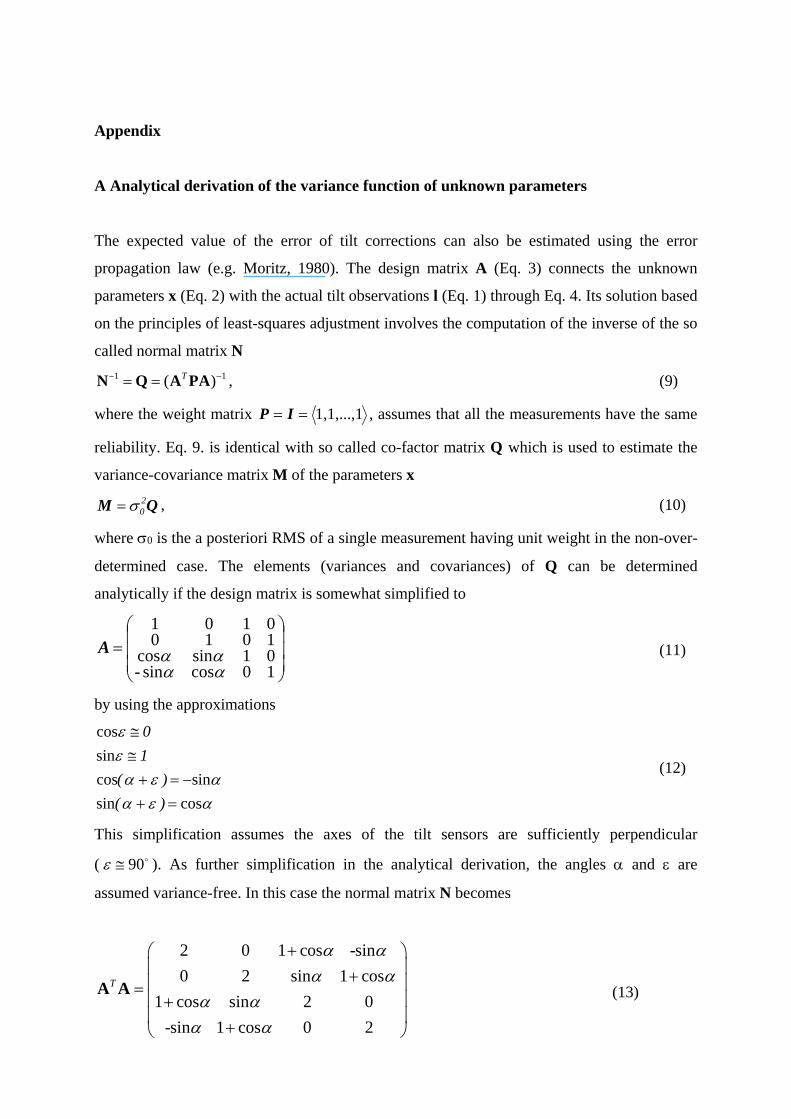
Appendix
A Analytical derivation of the variance function of unknown parameters
The expected value of the error of tilt corrections can also be estimated using the error
propagation law (e.g. Moritz, 1980). The design matrix A (Eq. 3) connects the unknown
parameters x (Eq. 2) with the actual tilt observations l (Eq. 1) through Eq. 4. Its solution based
on the principles of least-squares adjustment involves the computation of the inverse of the so
called normal matrix N
1 1( )T N Q A PA , (9)
where the weight matrix 1,1,...,1 IP , assumes that all the measurements have the same
reliability. Eq. 9. is identical with so called co-factor matrix Q which is used to estimate the
variance-covariance matrix M of the parameters x
QM 20 , (10)
where 0 is the a posteriori RMS of a single measurement having unit weight in the non-over-
determined case. The elements (variances and covariances) of Q can be determined
analytically if the design matrix is somewhat simplified to
10cossin-01sincos10100101
A (11)
by using the approximations
cossin
sincos
sin
cos
)(
)(
1
0
(12)
This simplification assumes the axes of the tilt sensors are sufficiently perpendicular
( 90 ). As further simplification in the analytical derivation, the angles and are
assumed variance-free. In this case the normal matrix N becomes
2 0 1 cos -sin
0 2 sin 1 cos
1 cos sin 2 0
-sin 1 cos 0 2
T
A A (13)
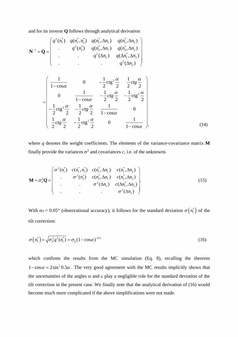
and for its inverse Q follows through analytical derivation
2 * * * * *1 1 2 1 1 1 2
2 * * *1 2 2 1 2 2
2 *1 1 2
22
2
2
2
( ) ( , ) ( , ) ( , )
. ( ) ( , ) ( , )
. . ( ) ( , )
. . . ( )
1 1 10 ctg
1 cos 2 2 2 21 1 1
0 ctg1 cos 2 2 2 2
1 1 1ctg 0
2 2 2 2 1 cos1 1
2 2 2
q n q n n q n n q n n
q n q n n q n n
q n q n n
q n
ctg
ctg
ctg
ctg
N Q
2 1ctg 0
2 1 cos
, (14)
where q denotes the weight coefficients. The elements of the variance-covariance matrix M
finally provide the variances 2 and covariances c, i.e. of the unknowns
2 * * * * *1 1 2 1 1 1 2
2 * * *2 2 2 1 2 20 2 *
1 1 22
2
( ) ( , ) ( , ) ( , )
. ( ) ( , ) ( , ).
. . ( ) ( , )
. . . ( )
n c n n c n n c n n
n c n n c n n
n c n n
n
M Q (15)
With 0 = 0.05“ (observational accuracy), it follows for the standard deviation *1n of the
tilt correction:
* 2 2 * 0.51 0 1 0( ) (1 cos )n q n (16)
which confirms the results from the MC simulation (Eq. 8), recalling the theorem
21 cos 2sin 0.5 . The very good agreement with the MC results implicitly shows that
the uncertainties of the angles and play a negligible role for the standard deviation of the
tilt correction in the present case. We finally note that the analytical derivation of (16) would
become much more complicated if the above simplifications were not made.
References
Abele M, Balodis, J, Janpaule I, Lasmane I, Rubans A and Zarinš, A 2012 Digital zenith camera for
vertical deflection determination Geodesy and Cartography 38 4 123-129
Bürki B, Müller A and Kahle H-G 2004 DIADEM: The New Digital Astronomical Deflection
Measuring System for Highprecision Measurements of Deflections of the Vertical at ETH
Zurich Electronic Proc. IAG GGSM2004 Meeting, Porto, Portugal. Published also in: CHGeoid
2003, Report 03-33 A (ed. U. Marti et al.), Bundesamt für Landestopographie (swisstopo),
Wabern, Switzerland
Chini R 2000 The Hexapod Telescope - A Never-ending Story. Reviews in Modern Astronomy 13, 257
Conti JP, Clinton CM, Zhang G and Wavering AJ 1998 Workspace variation of a hexapod machine
tool, NISTIR 6135, National Institute of Standards and Technology, Available
via:http://citeseerx.ist.psu.edu/viewdoc/download? doi=10.1.1.14.242
Csépány G, Pál A, Vida K et al 2014 The Fly's Eye Camera System -- an instrument design for large
étendue time-domain survey Astronomical Society of the Pacific proceedings (submitted)
Halicioglu K, Deniz R and Ozener H 2012 Digital zenith camera system for Astro-Geodetic
applications in Turkey Journal of Geodesy and Geoinformation 1 2 115-120 doi:
10.9733/jgg.131212.1
Hanada H, Araki H, Tazawa S et al. 2012 Development of a digital zenith telescope for advanced
astrometry SCIENCE CHINA Physics, Mechanics & Astronomy 55 4, 723-732, DOI:
10.1007/s11433-012-4673-1
Hirt C, Bürki B, Somieski A and Seeber G 2010 Modern Determination of vertical deflections using
digital zenith cameras Journal Surveying Engineering 136 1, 1-12. DOI:
10.1061/_ASCE_SU.1943-5428.0000009
Hirt C, Seeber G 2008 Accuracy Analysis of vertical deflection data observed with the Hannover
Digital Zenith Camera System TZK2-D Journal of Geodesy 82 6, 347-356. DOI:
10.1007/s00190-007-0184-7
Hirt C and Flury J 2008 Astronomical-topographic levelling using high-precision astrogeodetic
vertical deflections and digital terrain model data Journal of Geodesy 82 4-5, 231-248.
DOI:10.1007/s00190-007-0173
Hirt C 2008 Zur Berücksichtigung von Scherung und Umschlagwinkel bei der Neigungsmessung mit
zweiachsigen Neigungssensoren Zeitschrift für Vermessungswesen, 133 4, 266–273
Hirt C 2006 Monitoring and Analysis of Anomalous Refraction Using a Digital Zenith Camera System.
Astronomy and Astrophysics 459 1, November III 2006: 283-290. DOI: 10.1051/0004-
6361:20065485
Hirt C and Kahlmann T 2004 Hochpräzise Neigungsmessung mit dem elektronischen
Pendelneigungssensor HRTM Zeitschrift für Vermessungswesen 129 4, 266–276
Hirt C 2004 Entwicklung und Erprobung eines digitalen Zenitkamerasystems für die hochpräzise
Lotabweichungsbestimmung. Wissenschaftliche Arbeiten der Fachrichtung Geodäsie und
Geoinformatik an der Universität Hannover Nr. 253 (Dissertation), 188 pages.
Koch PM, Kesteven M, Nishioka H. et al. 2009 The AMIBA Hexapod Telescope Mount The
Astrophysical Journal 694 2, 1670 doi:10.1088/0004-637X/694/2/1670
Kudrys J 2009 Automatic determination of the deflections of the vertical – first scientific results Acta
Geodyn. Geomater. 6 3, 233-238
McCarthy DD 1976 Observations of the fortnightly nutation terms and the dynamical variation of
latitude with photographic zenith tubes The Astronomical Journal 81 482-484
Moritz H 1980 Advanced physical geodesy. Abacus Press, Tunbridge Wells, Kent, p. 500.
Metropolis N and Ulam S 1949 The Monte Carlo Method. Journal of the American Statistical
Association 44 247, 335–341. doi:10.2307/2280232
Ogrizovic V 2009 A construction of an advanced measuring system for astro-geodetic determinations,
Publ. Astron. Obs. Belgrade 86 145 - 150
Pál A, Mészáros L, Csépány G et al 2013 The Fly's Eye Camera System: An instrument design for
large étendue time-domain survey Astron. Nachr. 334, 932–935. doi: 10.1002/asna.201211962
Rubinstein RY and Kroese DP 2007 Simulation and the Monte Carlo Method (2nd ed.). New York:
Wiley & Sons. ISBN 978-0-470-17793-8.
Runge C 1894 Über die Bestimmung der geographischen Breite auf photographischem Wege
Zeitschrift für Vermessungswesen 23 300-304
Stewart, D 1965 A Platform with Six Degrees of Freedom Proceedings of the Institution of
Mechanical Engineers 180 15, 371–386
Torge, W 2001 Geodesy (3rd edition), de Gruyter, Berlin, New York.
Vida K, Pál A, Mészáros L, Csépány G, Jaskó A, Mező G, Oláh K 2014 The Fly's Eye project:
sidereal tracking on a hexapod mount. To appear in Proceedings Observing techniques,
instrumentation and science for metre-class telescopes (workshop Tatranská Lomnica, Slovakia,
September 23 - 26, 2013), available via eprint arXiv:1401.1719
Wang B, Tian L, Wang Z et al 2014 Image and data processing of digital zenith telescope (DZT-1) of
China, Chin. Sci. Bull., online first, DOI 10.1007/s11434-014-0277-7