ideas and tips on refurbishing zenith trans-oceanic 500 and
TRANSCRIPT
Ideas and Tips on Refurbishing Zenith Trans-Oceanic 500 and 600 Series Receivers
By Gary Clark – December 2011
Power Supply
Most people who refurbish old Trans-Oceanics recommend doing two things with the power supply:
1. Replace the selenium rectifier with a silicon diode 2. Replace all the electrolytic capacitors
In my opinion there is no good reason to replace either of these IF the existing parts are all working correctly. If the set is basically working from commercial power there are two simple tests to determine this.
TEST 1: Measure the dc voltage at the first filter capacitor (the 60 microfarad section of the multi-section can). The voltage should be about +105 V with the ac line input voltage at 115-120 volts.
If the voltage is correct (within 10%) you can assume the selenium rectifier is OK.
TEST 2: With the radio working and tuned between stations in a quiet area of any band, listen (or look with an oscilloscope) for hum in the output. Rotate the volume control from zero to the halfway point as you do this. (Unless it’s severe, you probably may not be able to hear hum using only the small built-in speaker but there are two other ways to do it.)
1. Connect a pair of modern stereo headphones to the headphone output. Modern headphones have very good low frequency response and, if there’s any hum, you’ll be able to hear it. (See paragraph on connecting ste-reo headphones to the headphone output.)
2. If you have an oscilloscope, connect it across the speaker terminals and measure the level of 60 Hz (or 50 Hz) ripple present.
If there’s no hum or ripple (or only a faint amount) you can assume the electrolytic filter capacitors are working correctly.
If you find that both the selenium rectifier and the electrolytic filter capacitors are OK, it’s up to you whether or not to replace either or both. They may still work well for many years (or they could fail tomorrow). But just because they are old does not mean they are going to fail soon. There’s really no way to predict this.
There are more arguments for keeping the filter capacitors than keeping the selenium rectifier. The capacitors are electrolytic with a dc working voltage of 150 (or higher) and in today’s solid state age there is little demand for electrolytics at the higher working voltages. That makes them expensive. Also, the electrolytics are (all but one) contained in a single can-type unit. It’s difficult to remove and finding a new can-type unit with all the same (or close) capacitances at 150 V or higher will be both difficult and expensive. So most people do the re-placement using four single tubular units (which still tend to be expensive at the higher voltages). This “crowds things up” under the chassis making access to other components difficult.
When electrolytic capacitors go bad they do so in one of three ways, they become leaky (electrically, not physi-cally*), they go open or they lose capacitance. Leaky electrolytic filter capacitors will be revealed by the dc voltage test (as long as the rectifier is good). The voltage measured will be too low. An open cap. will always produce very noticeable hum or ripple. A filter capacitor that has lost capacitance will produce hum, but much less than one that is open. Failure of the above-described hum test would be due to an open or low capacitance
1
unit. (* NOTE: Sometimes chemical will leak out of an electrolytic. If you have one like this, replace it.) Old electrolytic capacitors can often (even usually) be returned to service by a process called reforming. See the paragraph below titled Reforming Electrolytic Capacitors.
The argument for replacing the selenium rectifier is much stronger. When a selenium rectifier goes bad it can (but does not always) make a big stink. You really don’t want your house filled with selenium rectifier smoke. A more common failure mode is for the selenium rectifier to simply increase in internal resistance. This is the second reason (and probably the most common one) why the dc voltage test would be too low. It really is a good idea to replace the selenium rectifier, just on general principles.
When you replace the selenium rectifier, you also need to replace the power resistor(s) between the cathode (output end) of the rectifier and the first filter capacitor. This is because the new silicon diode has much lower internal resistance than the old selenium unit (even a good selenium unit). The reason for doing this is to pre-vent the dc voltage on the series-string tube filaments from going too high and risking tube burnout.
With all the above said, I would like to recommend a fairly simple modification to the 500 series power supply that does three things:
1. It replaces the selenium rectifier with a silicon diode. 2. It regulates the voltage on the filament string over a wide range of commercial power voltage variation. 3. It regulates the voltage on the B+ line over a wide range of commercial power voltage variation.
Items 2 and 3 above greatly improve receiver performance by stabilizing the local oscillator with line voltage variation, and preventing oscillator drop-out at low line voltage (both of which are known problems in 500 se-ries sets).
The modification involves replacing the selenium rectifier with a silicon diode and adding zener diodes to regu-late both the dc filament voltage and B+ voltage to “high enough but safe” levels.
2
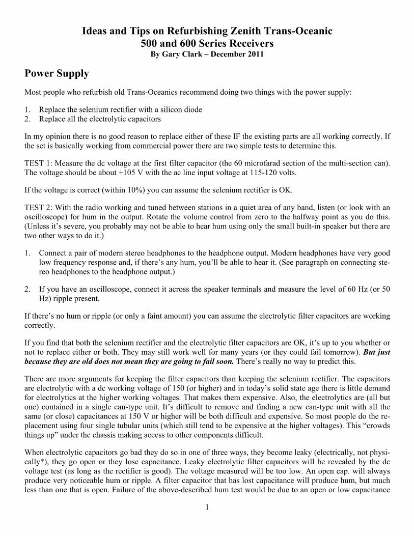
The modification requires two silicon diodes, two zener diodes, changing the values of some resistors and add-ing a fuse. It is shown in the figure above. Note that a half-amp fuse (not present in the original design) is added to the side of the power line that connects through switch S4 to circuit common. This is not an absolute re-quirement, but is a very good safety device that I think ought to be there. It is easy to mount on any chassis hav-ing a rear chassis mounted 1/4 inch headphone jack (which most H500 and early 600 series models have). Sets lacking the rear chassis mounted headphone jack would require drilling a half-inch hole in the chassis rear (if you use a type 3AG fuse and fuse holder, as I prefer).
The new rectifier is a type 1N4007 one amp 1000 PIV (Peak Inverse Voltage) silicon diode. These are very cheap. I bought some for ten cents each in December of 2011. The high PIV provides a safety margin. The sili-con diode has very low voltage drop compared to the original selenium rectifier. This increases the dc output voltage. The increase in dc output voltage is taken care of by increasing the values of resistors R40 and R41 and by the rest of the modified circuit because the zener regulated circuits now draw more current than before, pull-ing the voltage down.
The filament power supply is modified by changing resistors R51 and R52 from the original value of 950 ohms each down to 750 ohms each. This is to provide increased current which is taken up by the zener diode. The cir-cuit uses a 1N5333 which is a 9.1 volt 5 watt device. Since 9.1 volts is a little high for the filament string, the filament current is sent through another silicon diode before it goes to the tubes. This is the one labeled “any 100 V 1A silicon diode” in the above figure. Since the forward voltage drop of a silicon diode is about 0.6 V, this reduces the filament voltage to between 8.0 and 8.5 volts, which is ideal.
The values of R51 and R52 can be lowered from 950 ohms (original value) to approximately 750 ohms by shunting each of them with a 1500 ohm 5 W resistor, or the original resistors can be replaced using new 750 ohm 10 watt units. These resistors will get fairly hot, so keep them from touching wires or other components. In fact, if you can it’s a good idea to position them against the chassis so the chassis can act as a heat sink. Also, when you wire in the zeners, don’t clip the leads. Those heavy gage leads act as a heat sink, helping to make a five watt zener a 5W unit.
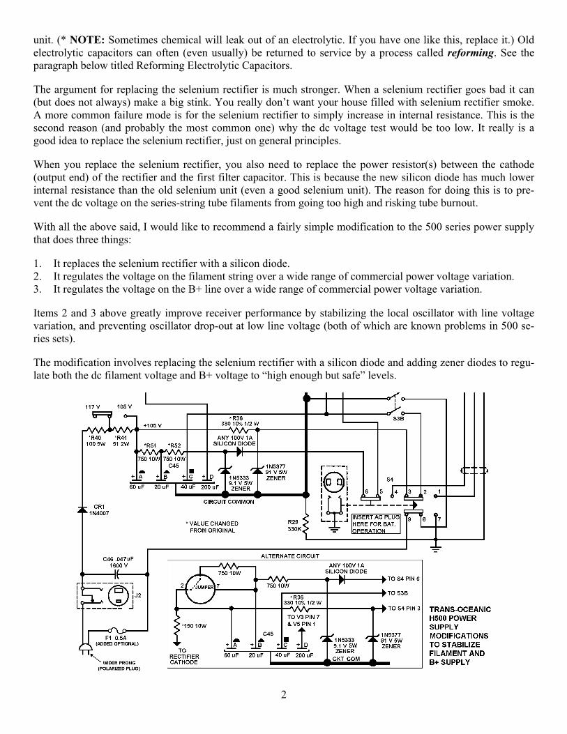
The 500 series (both G and H 500) always suffered from problems associated with varying power line voltage. At too low a filament voltage the 1L6 would stop oscillating at the higher shortwave frequencies. That’s the rea-son for the various “fixes” in the power supply over the life of the H500 model. Initially only a 130 ohm resistor
NEW FUSE HOLDER REPLACING PHONEJACK
0.047 uF CAP ACROSS AC LINE (REPLACED)
NEW 56 OHM 2W R41
RECTIFIER DIODE ZENER DIODE
NEW 10W RESISTOR
EXISTING DUAL 950 OHM RESIS-TOR R40-R41
NEW 100 OHM R40
TWO REPLACED BUMBLEBEE CAPS
100 uF FILTER CAP ADDED ACROSS 60 uF
3
was used between the rectifier cathode and the first filter capacitor. Later this was changed to the two resistor and switch circuit shown in the above schematic. Finally, near the end of the H500 production run, Zenith added a sixth tube socket for the 50A1 current regulator tube used in the military model. They didn’t sell the H500 with the 50A1 tube, but had a jumper in the socket and a note in the instruction book to replace that jumper with a 50A1 if varying line voltage caused problems. The 600 series models that replaced the H500 and came out in 1954 all contain the 50A1 tube which cured the filament voltage problem.
However all the Trans-Oceanic models using the 1L6 converter tube also have a problem of local oscillator fre-quency drift caused by changes in B+ voltage. This problem still exists in the 600 series. Regulating the 90 volt B+ line cures this problem. That’s why the power supply modification described above regulates both the fila-ment and the B+.
Using zener diode regulators increases the current draw on the power supply. This is no problem for the new silicon rectifier diode but it can increase hum due to the higher current putting increased load on the first filter capacitor. The above photo shows an extra 100 microfarad tubular electrolytic capacitor added across the exist-ing 60 microfarad filter. This was needed in my unit to totally eliminate hum.
For safety reasons you should also always replace the ac power cord with a new cord having a polarized plug, as shown in the previous schematic and the one below. See “The Power Cord” on page 8.
The 600 Series Power Supply
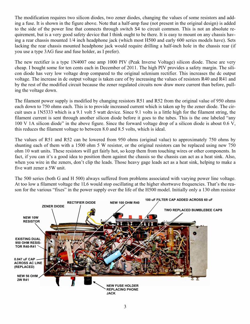
The 600 series sets all have a 50A1 series-regulator tube to regulate the filament current. These sets to not suffer from problems caused by changes in power line voltage altering the filament voltage. The only problem they do have is that voltage changes in the unregulated B+ line will cause some oscillator drift, particularly at the higher shortwave frequencies. This can be cured by adding the 91 volt zener. The modified circuit is shown below.
4
Re-forming Electrolytic Capacitors
When I refurbish any 500 or 600 series Trans-Oceanic the first thing I do is have a look at the can type electro-lytic filter capacitor. I look for any kind of white powder oozing out if it. If there is any, that capacitor must be replaced. But often there is no such evidence. When this is the case I attempt to salvage the filter capacitor by re-forming it. Even when I do have to replace one of those units I use “new old stock” capacitors that are many years old (but never used). Those capacitors have to be re-formed as well, before they are installed in the set.
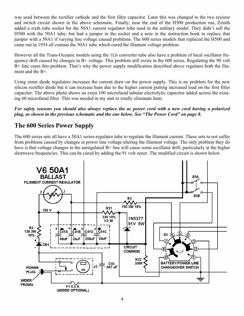
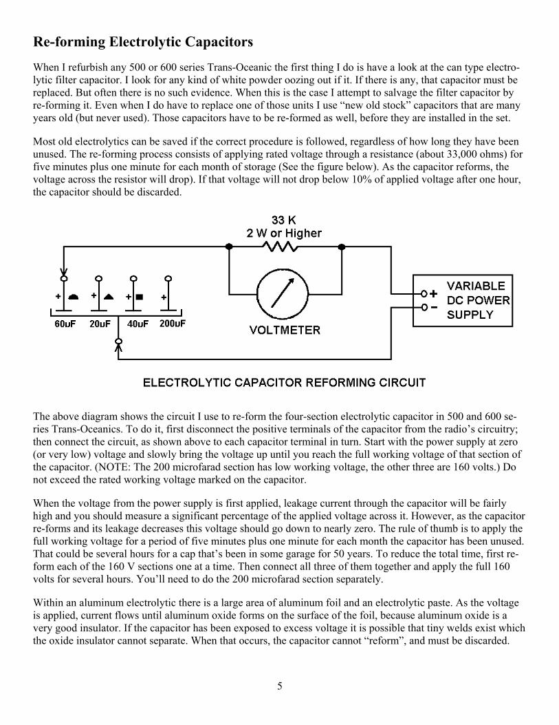
Most old electrolytics can be saved if the correct procedure is followed, regardless of how long they have been unused. The re-forming process consists of applying rated voltage through a resistance (about 33,000 ohms) for five minutes plus one minute for each month of storage (See the figure below). As the capacitor reforms, the voltage across the resistor will drop). If that voltage will not drop below 10% of applied voltage after one hour, the capacitor should be discarded.
The above diagram shows the circuit I use to re-form the four-section electrolytic capacitor in 500 and 600 se-ries Trans-Oceanics. To do it, first disconnect the positive terminals of the capacitor from the radio’s circuitry; then connect the circuit, as shown above to each capacitor terminal in turn. Start with the power supply at zero (or very low) voltage and slowly bring the voltage up until you reach the full working voltage of that section of the capacitor. (NOTE: The 200 microfarad section has low working voltage, the other three are 160 volts.) Do not exceed the rated working voltage marked on the capacitor.
When the voltage from the power supply is first applied, leakage current through the capacitor will be fairly high and you should measure a significant percentage of the applied voltage across it. However, as the capacitor re-forms and its leakage decreases this voltage should go down to nearly zero. The rule of thumb is to apply the full working voltage for a period of five minutes plus one minute for each month the capacitor has been unused. That could be several hours for a cap that’s been in some garage for 50 years. To reduce the total time, first re-form each of the 160 V sections one at a time. Then connect all three of them together and apply the full 160 volts for several hours. You’ll need to do the 200 microfarad section separately.
Within an aluminum electrolytic there is a large area of aluminum foil and an electrolytic paste. As the voltage is applied, current flows until aluminum oxide forms on the surface of the foil, because aluminum oxide is a very good insulator. If the capacitor has been exposed to excess voltage it is possible that tiny welds exist which the oxide insulator cannot separate. When that occurs, the capacitor cannot “reform”, and must be discarded.
5
Modifying the set to use modern stereo headphones
The headphone jack on the Trans-Oceanic was designed to use low impedance headphones that Zenith sold as an accessory. Only a limited number of them were ever sold, so it’s nearly impossible to find them today.
A much better option is to use a pair of modern stereo headphones, which are all low impedance. The only dif-ficulty this presents is connecting modern two-channel stereo headphones that use a mini stereo plug to a radio that has a 3/4 inch mono phone jack. My solution is to replace the original mono phone jack with a new mini stereo jack and mount the new stereo jack on the front panel of the radio (where it should be anyway).
NOTE: Only the H500 and the earlier 600 series sets had a rear chassis mounted 1/4 inch phone jack. Earlier models had a two-pin headphone connection on the rear chassis and late model 600 series moved the 1/4 inch phone jack to the front panel.
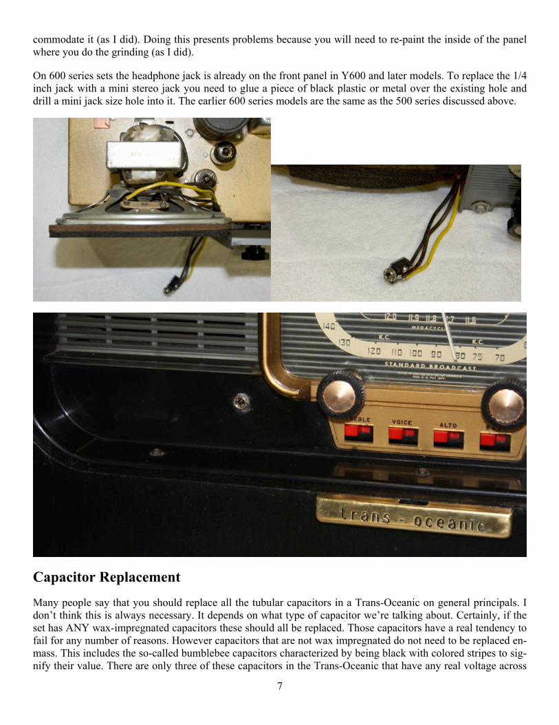
Removing the old chassis-mounted mono phone jack gives the added benefit of making it easy to mount a fuse holder for the new fuse discussed above. A type 3AG fuse holder will mount in the existing chassis hole with no modifications. The chassis photo above shows the fuse holder located where the old phone jack was.
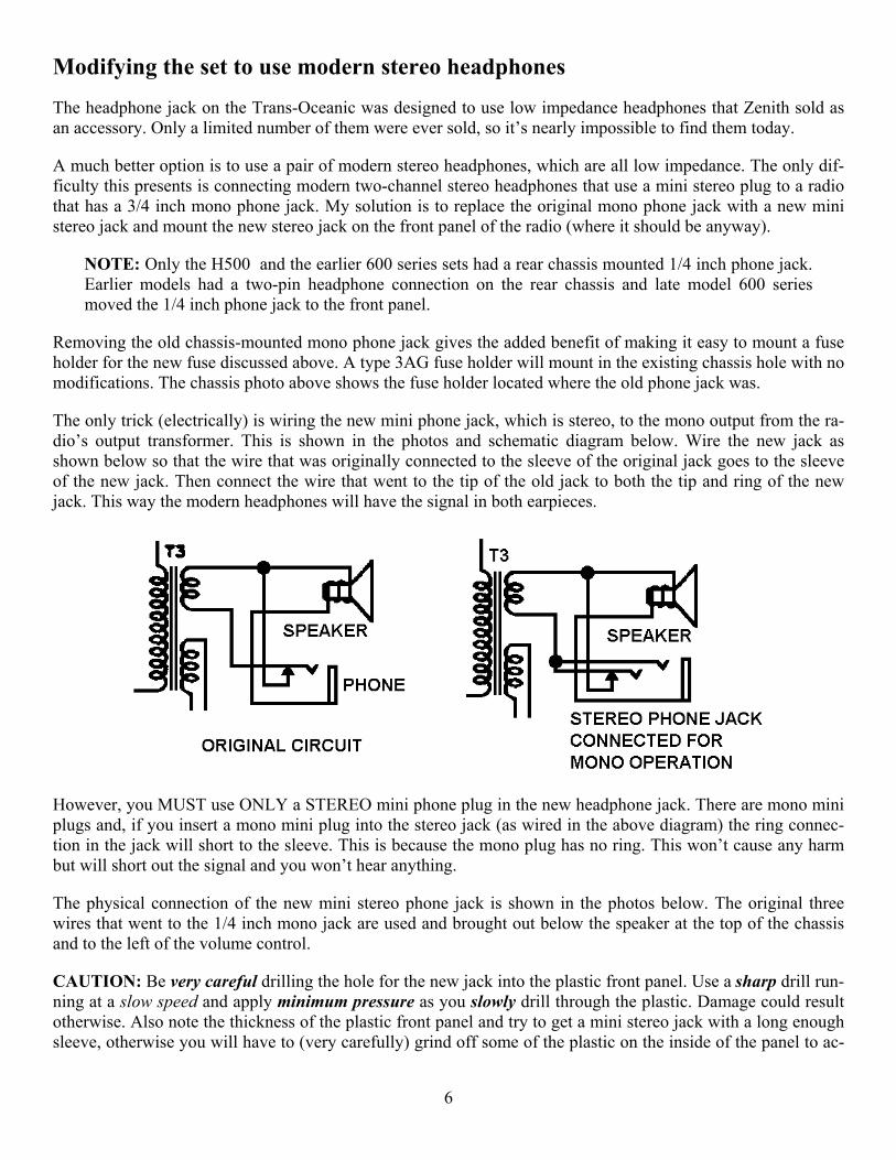
The only trick (electrically) is wiring the new mini phone jack, which is stereo, to the mono output from the ra-dio’s output transformer. This is shown in the photos and schematic diagram below. Wire the new jack as shown below so that the wire that was originally connected to the sleeve of the original jack goes to the sleeve of the new jack. Then connect the wire that went to the tip of the old jack to both the tip and ring of the new jack. This way the modern headphones will have the signal in both earpieces.
However, you MUST use ONLY a STEREO mini phone plug in the new headphone jack. There are mono mini plugs and, if you insert a mono mini plug into the stereo jack (as wired in the above diagram) the ring connec-tion in the jack will short to the sleeve. This is because the mono plug has no ring. This won’t cause any harm but will short out the signal and you won’t hear anything.
The physical connection of the new mini stereo phone jack is shown in the photos below. The original three wires that went to the 1/4 inch mono jack are used and brought out below the speaker at the top of the chassis and to the left of the volume control.
CAUTION: Be very careful drilling the hole for the new jack into the plastic front panel. Use a sharp drill run-ning at a slow speed and apply minimum pressure as you slowly drill through the plastic. Damage could result otherwise. Also note the thickness of the plastic front panel and try to get a mini stereo jack with a long enough sleeve, otherwise you will have to (very carefully) grind off some of the plastic on the inside of the panel to ac-
6
commodate it (as I did). Doing this presents problems because you will need to re-paint the inside of the panel where you do the grinding (as I did).
On 600 series sets the headphone jack is already on the front panel in Y600 and later models. To replace the 1/4 inch jack with a mini stereo jack you need to glue a piece of black plastic or metal over the existing hole and drill a mini jack size hole into it. The earlier 600 series models are the same as the 500 series discussed above.
Capacitor Replacement
Many people say that you should replace all the tubular capacitors in a Trans-Oceanic on general principals. I don’t think this is always necessary. It depends on what type of capacitor we’re talking about. Certainly, if the set has ANY wax-impregnated capacitors these should all be replaced. Those capacitors have a real tendency to fail for any number of reasons. However capacitors that are not wax impregnated do not need to be replaced en-mass. This includes the so-called bumblebee capacitors characterized by being black with colored stripes to sig-nify their value. There are only three of these capacitors in the Trans-Oceanic that have any real voltage across
7
them, the one across the ac line and two others. Those are the only ones I replace on general principals. If the set is working OK the capacitors are OK. Leave the rest of them alone. The above chassis photo shows which are the three capacitors to replace.
Non-electrolytic capacitors fail in three distinct ways. They go open, they short or they develop a high resis-tance internal leakage. Replacing working capacitors in circuits that don’t put any significant voltage across the capacitor does not make sense. In those circuits any capacitor that is working is likely to continue working. They don’t need to be replaced.
When you replace the .047 microfarad capacitor across the ac line, use a 1000 volt or 1600 volt unit if you can.
The Power Cord
Any Trans-Oceanic 500 or 600 series radio is 50 - 60 years old. Many need to have their power cords replaced simply because the existing cord is damaged or deteriorated. When you refurbish any of these sets you should always replace the power cord, and when you do, use a polarized cord (the kind with one prong wider than the other one). There were no polarized line cords in the 1940s and 50s when these Trans-Oceanics were made, so no set comes with one.
Replacing the power cord with a polarized cord will require you to slightly enlarge one of the slots in the chas-sis into which the power cord is inserted for battery operation. This is not too difficult using a small flat file with teeth on the file’s edge. Be sure you enlarge the slot that is NOT the one that engages the battery change-over switch. Damage to the switch may result otherwise.
When you replace the line cord, be SURE the wire connected to the wider plug prong is the one that connects [through the (newly added) fuse if you add it and] through the battery changeover switch to circuit common. This is both for personal safety reasons and for circuit grounding reasons.
I always buy a six foot extension cord with a polarized plug on one end and a three-way socket on the other. I cut off and discard the three-way socket and use the cord with polarized plug. This gives a very professional end result that looks like the new cord was there from the start.
NOTE: On 600 series sets, with the retracting power cord, this modification is a little harder to do than on the 500 series, but it can be done if you first take the battery changeover switch loose and move it out of the way. You will also have to wind the new cord onto the retracting reel, but that isn’t too hard to do, just take the reel off the chassis first.
Knobs
Both the 500 and 600 series sets have knobs with brass inserts. I have yet to see one with the inserts in good condition. More often than not they are missing. I use oil base gold paint to make the knobs resemble the origi-nal appearance. It’s a lot cheaper and easier than attempting to replace the insert. It doesn’t look exactly like the original, but it doesn’t look bad either.
External Antenna Modification
I have two sets I use frequently, an H500 in one room and a Y600 in anther. I also currently live in a building constructed with 10-inch thick steel reinforced concrete walls. This construction practically turns the building into a Faraday cage. You just can’t get any radio reception inside it, even on the broadcast band, except for the very strongest and closest stations. For this reason I put up an external long-wire antenna. Since I have two ra-dios, I need an external antenna on each of them, but one long wire antenna is all I can put up. So I connected
8
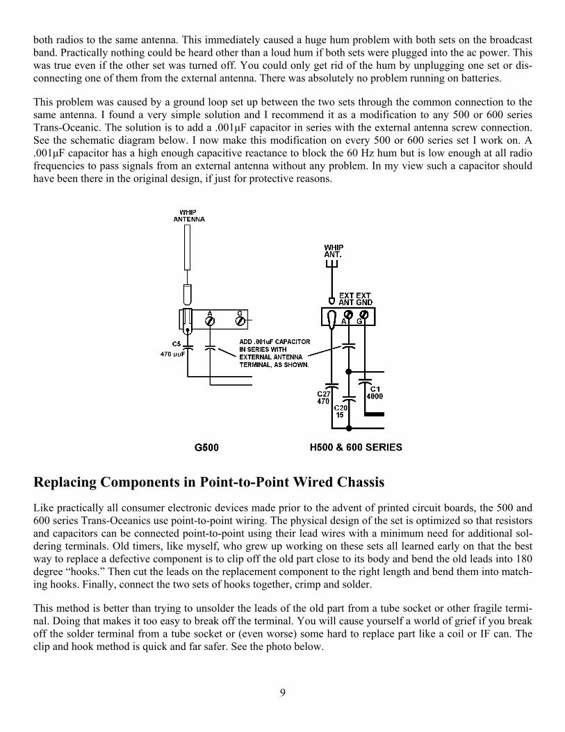
both radios to the same antenna. This immediately caused a huge hum problem with both sets on the broadcast band. Practically nothing could be heard other than a loud hum if both sets were plugged into the ac power. This was true even if the other set was turned off. You could only get rid of the hum by unplugging one set or dis-connecting one of them from the external antenna. There was absolutely no problem running on batteries.
This problem was caused by a ground loop set up between the two sets through the common connection to the same antenna. I found a very simple solution and I recommend it as a modification to any 500 or 600 series Trans-Oceanic. The solution is to add a .001µF capacitor in series with the external antenna screw connection. See the schematic diagram below. I now make this modification on every 500 or 600 series set I work on. A .001µF capacitor has a high enough capacitive reactance to block the 60 Hz hum but is low enough at all radio frequencies to pass signals from an external antenna without any problem. In my view such a capacitor should have been there in the original design, if just for protective reasons.
Replacing Components in Point-to-Point Wired Chassis
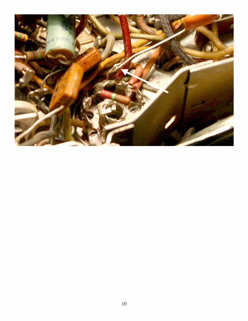
Like practically all consumer electronic devices made prior to the advent of printed circuit boards, the 500 and 600 series Trans-Oceanics use point-to-point wiring. The physical design of the set is optimized so that resistors and capacitors can be connected point-to-point using their lead wires with a minimum need for additional sol-dering terminals. Old timers, like myself, who grew up working on these sets all learned early on that the best way to replace a defective component is to clip off the old part close to its body and bend the old leads into 180 degree “hooks.” Then cut the leads on the replacement component to the right length and bend them into match-ing hooks. Finally, connect the two sets of hooks together, crimp and solder.
This method is better than trying to unsolder the leads of the old part from a tube socket or other fragile termi-nal. Doing that makes it too easy to break off the terminal. You will cause yourself a world of grief if you break off the solder terminal from a tube socket or (even worse) some hard to replace part like a coil or IF can. The clip and hook method is quick and far safer. See the photo below.
9
10