estimation of time offset in ofdm systems in the presence of cfo
TRANSCRIPT

I J E E C E5(2) July-December 2013; pp. 149-158
Estimation of Time Offset in OFDM Systems inthe Presence of CFO
Melkeri Vidyadhar S., Yamuna B. J. and Chetna Singhal DasSri Krishna Institute of Technology, Visvesvaraya Technological University, Bangalore
Abstract: Orthogonal frequency-division multiplexing (OFDM) has been adopted by manybroadband wireless communication systems for the simplicity of the receiver design tosupport high data rates and user mobility. However, studies also show that the advantageof OFDM over the single-carrier modulation schemes could be substantially compromisedby timing or frequency estimation errors at the receiver. The time synchronization problemfor OFDM systems is most common in the downlink of wireless communication systems, inthis paper a novel timing synchronization algorithm which minimizes false alarm probabilityand indirectly improves correct detection probability. We then introduce a universal fractionalcarrier frequency offset (CFO) estimator that outperforms conventional methods at low signalto noise ratio with lower complexity. More accurate timing and frequency estimates can beobtained by our proposed algorithms, presenting a successive timing estimation algorithmto solve the timing ambiguity. Both analytical and simulation results are presented to confirmthe performance of the proposed methods in various realistic channel conditions.
Keywords: OFDM, Cyclic prefix, Correlation, AWGN channel, Synchronization.
I. INTRODUCTION
In order to keep its technology competitive, 3rd Generation Partnership Project (3GPP) isconsidering long term evolution (LTE) [16], in which evolution of both radio interface andnetwork architecture is necessary. 3GPP LTE systems will provide higher data rate serviceswith better quality of service than the current 3G systems. This will require reliable and high-rate communications over time-dispersive (frequency-selective) channels with limited spectrumand inter-symbol interference (ISI) caused by multi-path fading. Orthogonal frequency divisionmultiple accesses (OFDMA) [16] [22] provide several advantages, such as high spectralefficiency, simple receiver design, and robustness in a multi-path environment. Due to theseadvantages, OFDMA was chosen as the downlink air interface of 3GPP LTE systems.
II. CYCLIC PREFIX
The cyclic prefix (CP) protects the OFDM symbols from ISI. The name of cyclic prefix indicateswhat it is and how it is generated. Firstly, as a prefix, it needs to be placed in the beginning ofan OFDM symbol. Secondly, being a cyclic extension to the original signal, the signal within
* Corresponding author: [email protected]; [email protected]; [email protected]

150 / MELKERI VIDYADHAR S., YAMUNA B. J. AND CHETNA SINGHAL DAS
the CP needs to be the same as the last portion of the OFDM symbol. Although the use of theCP prolongs the duration of OFDM symbols and results in a loss in data throughput, it hasbecome a common practice in most commercial OFDM systems because of the effectivenessin ISI mitigation.The benefit of the CP with an exemplary received waveform of one subcarrierin an OFDM signal. [16] [22], Without CP, it is inevitable for the FFT window to contain thesignals from two OFDM symbols.
As a result, the sudden phase change on the subcarrier spreads its spectrum into othersafter FFT and causes inter-carrier interference (ICI) that could significantly degrade the systemperformance. With the insertion of CP, which is assumed to be longer than the time intervalbetween the first and last channel paths, the phase discontinuity can be avoided by a properlylocated FFT window.
III. TIME DISPERSION
An uncorrupted OFDM signal can be demodulated without any interference between subcarriers.One way to understand this subcarrier orthogonality is to recognize that a modulated subcarrierx
k(t) consists of an integer number of periods of complex exponentials during the demodulator
integration interval Tu = 1/�f However, in case of a time-dispersive channel the orthogonality
between the subcarriers will, at least partly, be lost. The reason for this loss of subcarrierorthogonality in case of a time-dispersive channel is that, in this case, the demodulator correlationinterval for one path will overlap with the symbol boundary of a different path, as illustrated inFigure 1. Thus, the integration interval will not necessarily correspond to an integer number ofperiods of complex exponentials of that path as the modulation symbols a
k may differ between
consecutive symbol intervals. As a consequence, in case of a time-dispersive channel therewill not only be inter-symbol interference within a subcarrier but also interference betweensubcarriers [16]. If the correlation at the receiver side is still only carried out over a timeinterval Tu = 1/�f, subcarrier orthogonality will then be preserved also in case of a time-dispersivechannel, as long as the span of the time dispersion is shorter than the cyclic-prefix length. Inpractice, cyclic-prefix insertion is carried out on the time-discrete output of the transmitterIFFT. Cyclic-prefix insertion then implies that the last samples of the IFFT output block oflength N is copied and inserted at the beginning of the block, increasing the block length fromN to N + N
p at the receiver side Fig. 1. The cyclic-prefix insertion is beneficial in the sense that
it makes an OFDM signal insensitive to time dispersion as long as the span of the time dispersiondoes not exceed the length of the cyclic prefix.
IV. PERFECTLY SYNCHRONIZED SYSTEM
The perfectly synchronized system is said to be so, when there is no effect of CFO and TO inthe signal and the system is assumed to be free of inter-carrier interference (ICI) and inter-symbol interference (ISI). There is no block included to remove the effect of ICI or ISI, whichare mainly included due to the multipath fading of the OFDM signal.
V. NEED FOR SYNCHRONIZATION
If the Analog to Digital (AD) and Digital to Analog (DA) converters have different samplingclocks, then the mismatch in the clock speed between these two would lead to either an additional

ESTIMATION OF TIME OFFSET IN OFDM SYSTEMS IN THE PRESENCE OF CFO / 151
sample or loss of sample depending upon the relative speed between the two clocks. Also thereceiver side PC does not know where exactly the first sample of the first OFDM symboloccurs. This is where, time synchronization comes into play. Normally besides timesynchronization, we need to undertake frequency synchronization when there is a mismatchbetween the transmitter and receiver local oscillators. But in our case, as we use the same localoscillator in the transmitter and the receiver side, the frequency offset is zero.The need of theFrequency and Time synchronizations is a major part of the OFDM system which is needed forthe perfect reception of the transmitted signal. In OFDM, symbol-timing errors may causeinter-symbol interference (ISI). Since FFT windows can include adjacent OFDM symbolcomponents, this also leads to inter-channel interference (ICI) which causes essential degradationin channel estimation needed by coherent systems [16].
The synchronization issues in OFDM systems.
• The symbol timing synchronization, determinant of the correct symbol start position,i.e., the FFT window position before the FFT demodulation at the receiver end.
• The carrier frequency synchronization (i.e., carrier frequency recovery technique),utilized to eliminate the carrier frequency offset caused by the mismatch of the localoscillators between the transmitter and the receiver, nonlinear characteristic of thewireless channel as well as the Doppler shift.
• The sampling clock synchronization, which is to mitigate the sampling clock errorsdue to the mismatch of the crystal oscillators.
In most of the papers, the major disadvantage of compensation to the estimation of theoffset is when the presence of carrier frequency offset in the received signal due to the multipathfading of the received signal. Whereas in some of the papers the CFO effect is taken as constantwhich means the signal is perfectly synchronized which is not possible in the practical systems,and the estimation of the timing offset is calculated using different methods as listed
Figure 1: Time Dispersion and Corresponding Received Signal

152 / MELKERI VIDYADHAR S., YAMUNA B. J. AND CHETNA SINGHAL DAS
• Offset estimation using cyclic prefix• Pilot assisted estimation• ML estimation• Hybrid estimation etc.
VI. PROBLEM DEFINITION
In this paper a deep study about the algorithms proposed for calculating the timingsynchronization is done and considering the disadvantages of the above systems we have comeup with the novel time offset estimation method which has less effect of CFO and works in lowSNR, here we make use of the cyclic prefix for the estimation of the offset; the process forwhich is given in the second chapter. Our major problem statement is to estimate the exact timeoffset in the received signal and provide the offset to the receiver, so that the FFT window isplaced at the starting point of the data received. This is carried out by considering the effect ofCFO which mainly causes the failure of most of the estimation algorithms. Hence in our problemstatement we consider the effect of the CFO in the received signal and estimate the timingoffset, the performance analysis is made for different CFO values.
VII. SYNCHRONIZATION USING CYCLIC PREFIX
This is one of the blind synchronization method in which correlation is performed betweencyclic prefix (CP) and the last part of the OFDM symbol. Cyclic prefix (CP) which is a copy offinal piece of each subcarrier is inserted at the beginning of OFDM symbol. Length of thecyclic prefix should be long enough to ensure orthogonality of the system. However, theperformance of this method is seriously reduced in the time-variant multipath channel. Due tothe multipath components, the signals from different paths have different delays which mightprone a problem, as they do not arrive simultaneously.
The orthogonality between different subcarriers will be destroyed when integration is doneover entire symbol duration. The cyclic prefix based correlation technique is effective, whenlarge number of subcarriers is used. For frequency offset estimation, once the symbol timing isknown, the correlation output can be used to estimate the frequency offset. Initially, phase ofthe correlation output between the two samples is estimated and is divided by 2ðT, where T isthe time interval between the corresponding samples [4].
VIII. TIME-INVARIANCE PROPERTY OF RECEIVER
A system is called time-invariant or shift invariant, if its input-output characteristics do notchange with time. Let y(n) have system response T to the input signal x(n), represented as,
y(n) = T[x(n)]
Then if the same input signal is shifted by T units of time to yield, x(n – T) and applied tothe system (time invariant system), the response of the system should also be delayed by Tunits to yield.
y(n – T). That is,T[x(n–T)] = y(n–T) (2.10)

ESTIMATION OF TIME OFFSET IN OFDM SYSTEMS IN THE PRESENCE OF CFO / 153
For the system to be time invariant, the equation should hold for all possible values of, T.If it does not hold even for one value of T, then the system is time variant. The first uncertaintyis modeled as the delay in the channel impulse response which is modeled as �(k – T) where Tis the integer valued unknown arrival time of the received symbol the complete OFDM symbolreceived at the receiver is delayed by the value T hence it’s of major importance to calculatethe value of T and give it to the receiver to perform the correct FFT processing. In OFDMsystems, it is important to maintain the orthogonality between the subcarriers to avoid ICI.Though in our laboratory system we use the same local oscillators at the transmitter offset onthe autocorrelation property of the sequence just for completeness.
Considering we have a frequency offset of � in our system, sequence input to the correlate
will look like, 2k
jNe
�� where � denotes the difference in the transmitter and receiver oscillators
as s fraction of the inter-carrier spacing in normalized frequency, all the subcarriers experiencethe same shifts these two uncertainties and the AWGN thus yields to the received symbol.Receiver symbols can be modeled with both the uncertainties as given with the effect timingeffect T and the frequency effect � is given as
2( ) ( ) ( ) 0 1
kj
Ny k x k T e w k for k N��
� � � � �
The received signal y (k) is given as after removing the tap effects from the receivedframe
1
0
( ) ( ) ( ) ( ) 0 1N P
n
y k x n h k n w n for k N� �
�
� � � � � ��
The output of the transmitter is received by the receiver and the symbols received arecorrupted by both channel and AWGN noise showing uncertainty of time or frequency offset.Presently considering frequency offset as constant, let us calculate the timing offset as shownin the block diagram. The received symbols are correlated within the frame for the cyclicprefix with the copy of cyclic prefix in the same frame, which gives the peak value among thecorrelation. This is done for the complete block of symbols which is sent and the offset valueT is calculated as explained in the later sections. After getting the offset value of the symbolframe, the FFT window is moved to the starting position of the frame and the FFT process isdone to get back the signal. Using the correlation values which is obtained by moving windowcorrelation of CP to CP these values have the highest peak value when the data is correlated,by making use of these
1*
0
( ) { ( ) ( )}p L
k
c k y k y k N� �
�
� ��
Correlation values c(k) the peak position is calculated and FFT window is moved to thepeak position, hence providing the correct demodulation of the received signal. Many of thealgorithms are provided to find the Time offset and the Carrier frequency offset in the receivedframe which are given in the literature survey [17].
154 / MELKERI VIDYADHAR S., YAMUNA B. J. AND CHETNA SINGHAL DAS
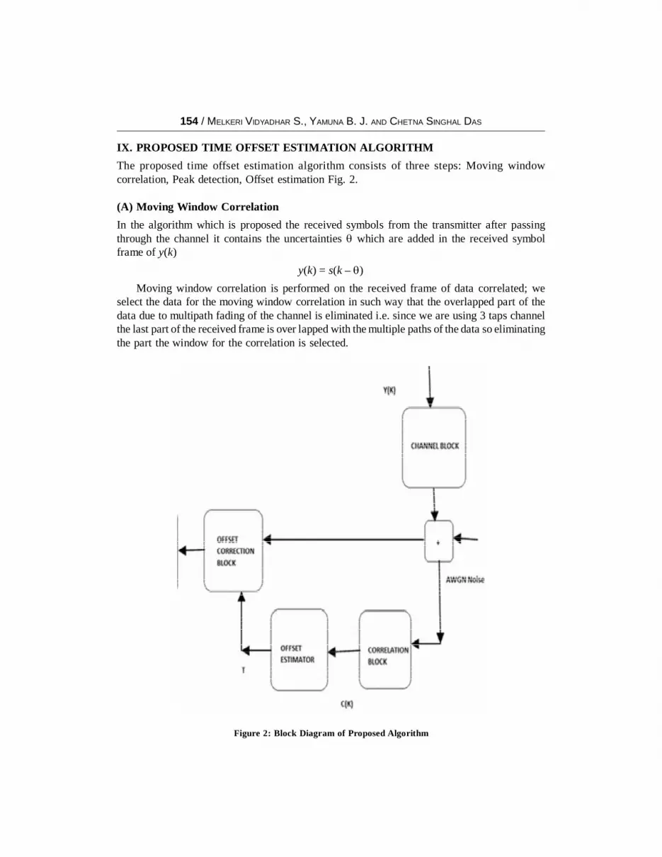
IX. PROPOSED TIME OFFSET ESTIMATION ALGORITHM
The proposed time offset estimation algorithm consists of three steps: Moving windowcorrelation, Peak detection, Offset estimation Fig. 2.
(A) Moving Window Correlation
In the algorithm which is proposed the received symbols from the transmitter after passingthrough the channel it contains the uncertainties � which are added in the received symbolframe of y(k)
y(k) = s(k – �)
Moving window correlation is performed on the received frame of data correlated; weselect the data for the moving window correlation in such way that the overlapped part of thedata due to multipath fading of the channel is eliminated i.e. since we are using 3 taps channelthe last part of the received frame is over lapped with the multiple paths of the data so eliminatingthe part the window for the correlation is selected.
Figure 2: Block Diagram of Proposed Algorithm

ESTIMATION OF TIME OFFSET IN OFDM SYSTEMS IN THE PRESENCE OF CFO / 155
(B) Peak Detection and Averaging
After performing the correlation using moving window, we obtain the graph of random peaks,in this process the average sum of the peak data of the frame from graph is calculated byshifting the selection of the position by the frame length and are averaged to get the maximumvalue, i.e. using 1st symbol of first frame and first symbol of second frame is added in this wayjump is performed for length of frame, so that we obtain N number of the values added amongwhich the perfectly correlated symbols will be having the highest peak average value by whichwe can give the starting position of the frame, here the complete data is correlated using movingwindow with the length of cyclic prefix but removing the taps effect from the correlating data,
(C) Time Offset Estimation
The offset estimation of the symbols is carried out as follows, the received symbols are delayedfor the integral value assuming the integer value � is the offset in the received symbols, whichdelays the received symbols then the received symbols are correlated, Fig 3.1 but in thiscorrelation the length of data used is only for the one frame length, the correlation process issame as explained in the section A Fig. 3.2.
The obtained correlation results are used to get the peak position within the frame; theselected received frame for the correlation will be having the peak position of the secondframe. Using this position it’s compared with the length of the frame and the estimated offset isobtained this offset value is given to receiver to correctthe starting position of the receiverframe for the processing of the FFT to obtain the received data.
X. RESULT ANALYSIS
Figure 3.1: SNR = 5, CP=64, N=1024 before Offset

156 / MELKERI VIDYADHAR S., YAMUNA B. J. AND CHETNA SINGHAL DAS
The below simulation results gives the offset estimation of algorithm for different SNRvalues the offset given is 10 and SNR ranges from 0db-30db Fig. 4.
Figure 3.2: SNR=5, CP=64, N=1024 after Offset
Figure 4: CP=32, N=1024, TAPS=3, DIFFERENT SNR

ESTIMATION OF TIME OFFSET IN OFDM SYSTEMS IN THE PRESENCE OF CFO / 157
XI. CONCLUSION
OFDM is an emerging modulation technique to handle impairments of frequency selectivefading channel. Hence, OFDM is a prime candidate for future wireless communicationtechniques. One of the major drawbacks of OFDM system is the shift or the uncertainty in thetiming of the symbols i.e. time offset in the system which is due to the data rotation and due tomultipath fading of the channel as the channel involved is air.
XII. SCOPE FOR FUTURE WORK
As we have seen in the above proposed method, there is a lot of scope for future work whichgives the platform for further development of the system. Time synchronization in the OFDMsystem is the major issue which needs to be corrected before further processing blocks in thereceiver systems.
The program complexity can be further reduced for the faster calculation in estimating theoffset in the system. In most of the proposed algorithm the offset estimation is mainly dependenton following issues.
1. System should be perfectly synchronized.
2. The effect off carrier frequency offset should be neglected.
3. The effect of SNR is more random.
4. Noise variance of the system.
5. Threshold dependent.
In most of the proposed algorithms the effect of carrier frequency offset is neglected butwhere as in the proposed algorithm it is been checked for the correctness of the estimation forthe different Doppler effects the system works correct up to 0.1 Doppler effect in the transmitteddata symbols, hear further work can be done to improve the estimation for Doppler effectwhich is more then 0.1, for the high performance in the system.
Acknowledgment
The joy of accomplishing a task on hand will last a lifetime only if we humbly acknowledge the people whohave played a significant part in its fulfillment. This, we feel a genuine way of expressing our gratitude andfeelings in the simplest manner. I express my deep sense of gratitude to Dr. Raghunath K, and Dr. Vijaykrishna for his inspiring guidance, encouragement, and continuous supervision throughout the paper work tillthe completion of the paper. Last but certainly not the least; I would like to thank the almighty, my family anddear friends, who blessed, supported and helped me during the entire length of my paper work.
References
[1] Jan-Jaap van de Beek, Magnus Sandell, and Per Ola Borjesson, “ML Estimation of Time and FrequencyOffset in OFDM Systems” IEEE Transactions on Signal Processing, Vol. 45, No. 7, 1997.
[2] Daniel Landstrom, Sarah Kate Wilson, Jan-Jaap van de Beek, Per Odling, and Per Ola Borjesson, “SymbolTime Offset Estimation in Coherent OFDM Systems” IEEE Transactions on Communications, Vol. 50,No. 4, 2002.
[3] Yanxin Yan and Masayuki Tomisawa, “Joint Timing and Frequency Synchronization for IEEE 802.16OFDM Systems” Mobile Wimax Symposium, 2007. PAGE 17-21 IEEE.

158 / MELKERI VIDYADHAR S., YAMUNA B. J. AND CHETNA SINGHAL DAS
[4] J. Lee, H. Lou and D. Toumpakaris, “Maximum Likelihood Estimation of Time and Frequency Offset forOFDM Systems” Electronics Letters 28th October 2004, Vol. 40, No. 22
[5] J. D. Bakker, “Eliminating the OFDM Cyclic Prefix” Personal, Indoor and Mobile Radio Communications,2002. The 13th IEEE International Symposium on, 2002 IEEE, Page 834-837, Vol. 2.
[6] Yingming Tsai and Guodong Zhang, “Time and Frequency Synchronization for 3GPP Long Term EvolutionSystems” Vehicular Technology Conference, 2007. VTC2007-spring. IEEE 65th, pp. 1727-1731, 2007IEEE.
[7] Andreas Ibing, KonstantinosManolakis, “MMSE Channel Estimation and Time Synchronization Trackingfor Cooperative MIMO-OFDM with Propagation Delay Differences” Wireless Communication Systems.2008. ISWCS ’08. IEEE International Symposium on 2008 IEEE. Page 433–437.
[8] Han Gujing, “An Highly-effective Time and Frequency Synchronization Scheme for OFDM WirelessCommunication System” Microwave, Antenna, Propagation and EMC Technologies for WirelessCommunications, 2009 3rd IEEE International Symposium on 2009 Ieee, Page 456–461.
[9] HeeWook Kim, Seung-min Lee, Kunseokkang and Do-SeobAhn “Blind Time and FrequencySynchronization in OFDM based Communication” Vehicular Technology Conference, 2006. VTC-2006Fall. 2006 Ieee 64th Page 1-5.
[10] Wen-Long Chin “ML Estimation of Timing and Frequency Offsets Using Distinctive CorrelationCharacteristics of OFDM Signals Over Dispersive Fading Channels” Vehicular Technology, IEEETransactions on 2011 IEEE, PAGE 444 – 456, Vol. 60.
[11] Shaodan Ma, Xinyue Pan, Guang-Hua Yang, and Tung-Sang Ng, Fellow, “Blind Symbol SynchronizationBased on Cyclic Prefix for OFDM Systems” Vehicular Technology, IEEE Transactions On IEEE 2009,Vol. 48, pp. 1746–1751.
[12] Jan-Jaap van de Beek Magnus SandellPer Ola BÄorjesson, “On Synchronization in OFDM SystemsUsing the Cyclic Prefix” Lulea University of Technology S 971 87 Lulea, Sweden.
[13] 3GPP Long Term Evolution (LTE), TCSET’ 2010, February 23-27, 2010, Lviv-Slavske, Ukraine.
[14] Xuefenzhang “A Robust Timing Offset Tracking Scheme for SC-FDE System” Wireless Communications,Networking and Mobile Computing, 2008. wicom ’08. 4th International Conference on 2008 IEEE, pp.1-4.
[15] “Robust Synchronization for 3GPP LTE System” globecom 2010, 2010 IEEE Global TelecommunicationsConference on dec 2010 IEEE.
[16] Erik Dahlman, Stefan Parkvall, Johan Sköld and Per Beming, “3G Evolution HSPA and LTE for MobileBroadband” British Library Cataloguing in Publication Data, First Edition 2007.
[17] Michele Morelli, C. C. Jay Kuo, and Man-On Pun, “Synchronization Techniques for Orthogonal FrequencyDivision Multiple Access (OFDMA)”, Proceedings of the IEEE | Vol. 95, No. 7, 2007.
[18] Bernard Sklar “Digital Communications Fundamentals and Applications” Prentice Hall P T R, Secondedition.
[19] Oppenheim Schafer “Discrete-Time Digital Signal Processing”, 1999, 1998 Published by Prentice Hall,First edition.
[20] John G Proakis “Digital Communications” Published by Tata McGraw Hill Fourth Edition.
[21] Simon Haykin “Communication Systems” Published by John willey and sons Fourth Edition 2001.
[22] Richard van Nee and RamjeeParsad “OFDM for Wireless Communication” 2000 Edition.
[23] Gerard Blanchet & Maurice Charbit “Digital Signal and Image Processing Using MATLAB” by HERMESScience Europe Ltd, 2001, ISTE Ltd, 2006.
[24] Andrew Knight “Basic of Matlab and Beyond” by CHAPMAN & HALL/CRC 2000 Edition CRC PressLLC.
[25] Simon Haykin “Statistical signal processing” Published by John willey and sons Fourth Edition 2004.