encapsulation of 2-amino-2-methyl-1-propanol with tetraethyl
TRANSCRIPT
RESEARCH ARTICLE
Encapsulation of 2-amino-2-methyl-1-propanol with tetraethylorthosilicate for CO2 capture
Sidra Rama1, Yan Zhang1, Fideline Tchuenbou-Magaia2, Yulong Ding1, Yongliang Li (✉)1
1 School of Chemical Engineering, University of Birmingham, Edgbaston, Birmingham B12 2TT, UK2 School of Engineering, University of Wolverhampton, Wolverhampton WV1 1LY, UK
© The Author(s) 2019. This article is published with open access at link.springer.com and journal.hep.com.cn 2019
Abstract Carbon capture is widely recognised as anessential strategy to meet global goals for climateprotection. Although various CO2 capture technologiesincluding absorption, adsorption and membrane exist, theyare not yet mature for post-combustion power plantsmainly due to high energy penalty. Hence researchers areconcentrating on developing non-aqueous solvents likeionic liquids, CO2-binding organic liquids, nanoparticlehybrid materials and microencapsulated sorbents tominimize the energy consumption for carbon capture.This research aims to develop a novel and efficientapproach by encapsulating sorbents to capture CO2 in acold environment. The conventional emulsion techniquewas selected for the microcapsule formulation by using2-amino-2-methyl-1-propanol (AMP) as the core sorbentand silicon dioxide as the shell. This paper reports thefindings on the formulated microcapsules including keyformulation parameters, microstructure, size distributionand thermal cycling stability. Furthermore, the effects ofmicrocapsule quality and absorption temperature on theCO2 loading capacity of the microcapsules were investi-gated using a self-developed pressure decay method. Thepreliminary results have shown that the AMP microcap-sules are promising to replace conventional sorbents.
Keywords carbon capture, microencapsulated sorbents,emulsion technique, low temperature adsorption andabsorption
1 Introduction
The global industrialization and growing population havebrought a yearly increase in energy consumption. Theestimated global energy-related emission increase ispredicted to be 3.7 Gt of CO2 by 2030 [1]. The increase
of CO2 emission into the environment has contributed toglobal warming as well as climate change which is aprimary concern today. In the foreseeable future, fossilfuels will still be used for most of electrical powergeneration and industrial manufacturing in many countries[2]. Scientists speculate that at least 69% of CO2 emissionand 60% of greenhouse gases are produced through energygeneration, whereas 80% of the world energy is derivedfrom fossil fuel. The International Agency has reported a6% increase in CO2 emission every two years due to thedependency of the world economy on fossil fuels for anenergy source. Even the Nobel Prize-winning Intergovern-mental Panel have concerns and advise that a cut of 50%–80% is required by 2050 to avoid the most harmful effectsof climate change [3]. Furthermore, industries such asrefinery plants, ammonia synthesis plants and hydrogenmanufacturers also require the removal of CO2 to preventthe corrosion of pipeline, catalyst poisoning and cloggingdue to dry ice formation. One of the most promisingapproaches to tackle the high emission rate of CO2 is theuse of carbon capture and storage technology, which aimsat capturing CO2 from power stations and other industrialfacilities, compressing, and then transporting it to under-ground storage locations.Although various CO2 capture technologies exist
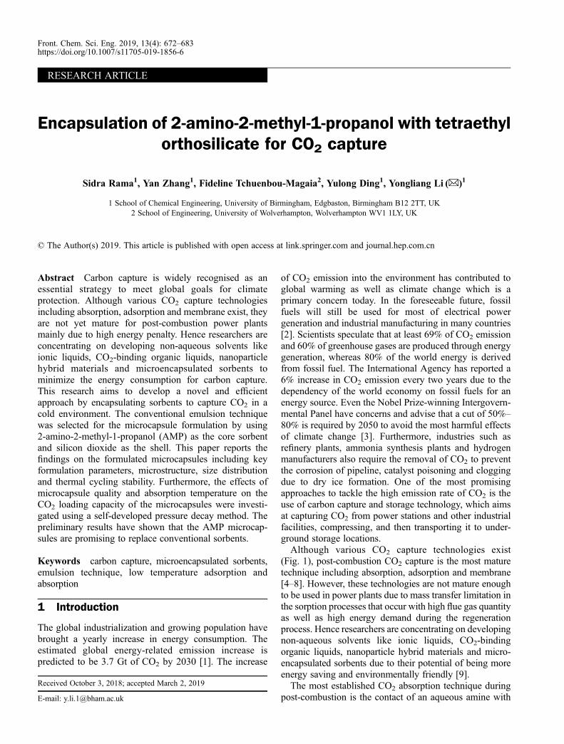
(Fig. 1), post-combustion CO2 capture is the most maturetechnique including absorption, adsorption and membrane[4–8]. However, these technologies are not mature enoughto be used in power plants due to mass transfer limitation inthe sorption processes that occur with high flue gas quantityas well as high energy demand during the regenerationprocess. Hence researchers are concentrating on developingnon-aqueous solvents like ionic liquids, CO2-bindingorganic liquids, nanoparticle hybrid materials and micro-encapsulated sorbents due to their potential of being moreenergy saving and environmentally friendly [9].The most established CO2 absorption technique during
post-combustion is the contact of an aqueous amine with
Received October 3, 2018; accepted March 2, 2019
E-mail: [email protected]
Front. Chem. Sci. Eng. 2019, 13(4): 672–683https://doi.org/10.1007/s11705-019-1856-6
flue gas to form carbamates as the amine reacts with CO2.The commonly used amine is monoethanolamine (MEA)which has a high absorption rate and loading capacity.However, drawbacks such as high corrosivity, toxicdegrading side-products and high amount of energyrequired for CO2 removal during the sorbent regenerationprevent its widespread use. Thus, new sorbents areproposed to overcome these limitations by combining theliquid sorbents (core) with solid ones (shell) therebyforming microcapsules. The liquid solvent would providehigh capacity, selectivity as well as water tolerance,whereas the solid sorbents would provide a high surfaceand in turn higher absorption capacity as well as lowvolatility [11]. Moreover, microencapsulation can alsolower the cost of CO2 capture by containing precipitates,and isolate the solvent from reactor equipment [12].Microencapsulation is defined by either enveloping or
surrounding one substance within a different substance at asmall scale to yield micro-sized capsules. The micro-encapsulated material has limitless applications such aspharmaceuticals, cosmetics, textiles, agriculture, foods,paints, coatings and fragrances [13]. The microcapsule canvary in shape from spheres with a core surrounded by acontinuous wall to asymmetrical with various shapescontaining embedded droplets of core material throughoutthe capsules. Hence, it can provide more comfortablehandling of liquid and gas material as solids, whileallowing a measure of protection against hazardousmaterial handling. In the case of carbon capture, themicrocapsules can offer the potential of combiningchemical absorption of CO2 with physical adsorption.Chemical absorption creates chemical bonding betweenthe chemical solvent and the captured CO2, whereas thephysical adsorption allows gas permeation or desorptioninto solid/ liquid under specific conditions. Temperatureand pressure control the rate of desorption or absorptionand therefore, eliminate the need for the production ofhazardous products.In recent years, microcapsules composed of liquid
carbonate cores and silicone shells have been producedusing a microfluidic device. The idea was to link the liquidsorbents selectivity and capacity with the high surface areaof the capsules for fast and controlled CO2 absorption anddesorption over multiple cycles. Their study reported alower mass transport across the capsule shell compared toconventional liquid sorbents. However, the enhancedsurface area gained through encapsulation delivered anincrease in CO2 absorption rate for the given sorbent mass[11]. Another study by the same research group demon-strated an increased rate of CO2 absorption by a factor of3.5 with encapsulated ionic liquids in a silicon shell, whencompared to a liquid film. However, these solvents arehighly viscous or change phases, posing challenges forconventional process equipment [14].In the present study 2-amino-2-methyl-1-propanol
(AMP) is used instead as the core sorbent as it is of lowviscosity, easy to process and has high CO2 sorptioncapacity. Our research aims to produce porous micro-capsules with highly permeable shells and high sorptioncapacity core for efficient CO2 capture using conventionalformulation technology. As a widely known method formicroencapsulation, the emulsion technique was chosenfor the encapsulation process due to the potential ofencapsulating hydrophobic and hydrophilic substances[15,16]. The effect of stirring speed during formulation,thermal properties, the payload of the formulated micro-capsules, as well as sorption capacity of the producedmicrocapsules, were investigated as well for its potentialindustrial applications. The results are expected to providean alternative CO2 absorption technique to the current CO2
capture technologies.
2 Materials and methods
2.1 Chemicals
AMP (> 98%) is chosen as the core materials; Tetraethyl
Fig. 1 Illustration of the different pathways for CO2, N2 and O2 separation [10].
Sidra Rama et al. Encapsulation of 2-amino-2-methyl-1-propanol for CO2 capture 673
orthosilicate (TEOS,> 99%) is chosen as the shell materialdue to its high permeability to gases, compatibility with thecore as well as immiscibility with the formulation oil.Other chemicals used in the formulation process includethymol blue, polyglycerol polyricinoleate (PGPR,> 99%)and mineral oil (> 99%) (Table 1). All these chemicalswere purchased from Sigma Aldrich, UK.
2.2 Formulation of microcapsules
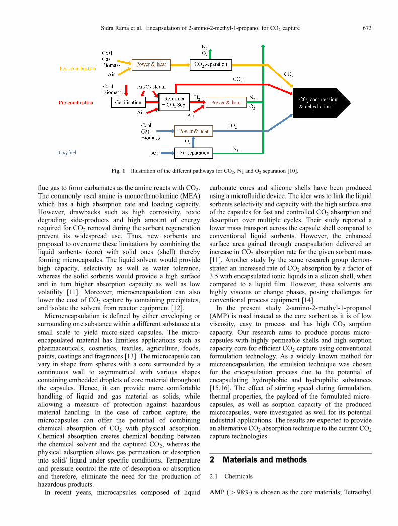
The microencapsulation process includes the emulsion ofAMP into a mineral oil followed by the polymerization ofthe silica precursors to form the shell as shown in Fig. 2.During core preparation, 15 g of the colorless, liquid AMPis mixed with 1 g of Thymol blue, a pH indicator, to give ablue colored AMP solution. The purpose of the dye is toenable qualitative analysis of CO2 capture into theencapsulated AMP. Meanwhile, 10 g TEOS is mixedwith 2 g of 0.5% sodium hydroxide (NaOH) to start thealkaline polymerization of the silica. In the formulationprocess, 70 g of mineral oil with 0.35% PGPR, asurfactant, is added to a jacketed beaker connected to a
water bath. The temperature of the water bath is keptconstant at 20°C throughout the whole encapsulationprocess. The oil is mechanically stirred (IKA). The AMPsolution with the pH indicator is added to the oil phase byslow pipetting. Due to the immiscibility of the oil and core,small core droplets are formed, providing an interface forthe TEOS particles in a later stage. Afterwards, activatedTEOS is slowly pipetted into the oil phase. During theencapsulation, three different stirring speeds were used:(1) 100 r/min; (2) 400 r/min; and (3) 600 r/min, toformulate three samples (Sample 1, 2 and 3 respectively).During the formulation process, the whole system iscovered up to prevent solvent evaporation. Furthermore,the whole process takes place under constant temperatureand mechanical stirring for at least≥12 h. Afterwards, thesample is centrifuged and repeatedly washed with hexane(≥99%) to remove excess oil, unencapsulated AMP,oligomers of TEOS particles and then vacuum dried. Oncethe microcapsules are successfully formulated, the sampleis characterized and tested for CO2 absorption.
2.3 Microcapsules characterization
The internal structure, morphology, size uniformity andaggregation of the formulated microcapsules were exam-ined using scanning electron microscopy (Hitachi TabletopTM3030 SEM) with backscattered electrons at 15 kV. Thesamples were coated with 3 nm gold (gold splutteringmachine) before each test. The size distribution of themicrocapsule was determined by utilising a MalvernMasterSizer 2000 that uses the static light scattering and
Table 1 Important features of the materials used for microencapsula-
tion
Function Material Features
Core AMP Highest CO2 loading capacity,low regeneration temp
Shell TEOS Permeability to gas
Immiscible phase Mineral oil Immiscibility with core
Fig. 2 Schematic diagram of the microencapsulation of AMP with TEOS (*varying stirring speeds used).
674 Front. Chem. Sci. Eng. 2019, 13(4): 672–683
the Mie scattering theory. These theories assume that allparticles are spherical with larger particles scatter light at asmaller angle than smaller ones. This MasterSizer usedworks in the size range of 0.02 to 2000 µm. To identify themicrocapsule size, the refractive index of the shell and thesolvent liquid needs to be known. The refractive index forboth silicon dioxide and ethanol were taken from theliterature and are 1.45 and 1.36, respectively. The resultsare shown as the average values of 3 data sets. The specificsurface area (m2/g), average pore volume (cm3/g) and poresize (Å) of the formulated microcapsules were measuredand calculated using a Bruner-Emmett-Teller (BET)instrument (Micrometrics TriStar II Plus). The samplewas inserted into the instrument after a pretreatment undervacuum at room temperature to ensure that the sample iscompletely dried. The standard measurement points usedwere P/P0 of 0.1, 0.2 and 0.3. The absorbed gas volume onparticle surface was measured at the boiling point ofnitrogen (–196°C). The amount of adsorbed and desorbedgas was then correlated to the total surface area includingthe pore volume and size at the surface. The calculatedvalues are based on the BET theory. Gas adsorption alsoenables the determination of size and volume distributionof pores.Thermal stability of the formulated microcapsules was
investigated using differential scanning calorimetry(DSC2, STARe System; Mettler Toledo) and dilatometer.In DSC measurement the test temperature range was 25°Cto – 60°C. In dilatometer measurement 10 continuousthermal cycling between 25°C and – 100°C were carriedout and samples were then observed for any changes inphysical properties such as shape and size. The chemical
composition and stability of the formulated microcapsuleswere measured using Fourier transform infrared spectro-scopy (FTIR) which can identify bonds present inside thesamples [17]. For comparison purpose, the encapsulatedsample was run against pure core material.The payload (amount of AMP content inside the sample)
of the formulated microcapsules was identified using athermogravimetric analysis (Mettler Toledo). To this end,10–20 mg of sample was heated above the boilingtemperature of the core material (250°C for AMP), andthe temperature is kept constant at that temperature for 2 hto evaporate all the core material. The payload is thencalculated as follows:
f ¼ mI –mS
mI� 100%, (1)
where f is payload (wt-%); mI is the initial weight ofsample; mS is the weight of shell after the core evaporationprocess.
2.4 CO2 sorption process
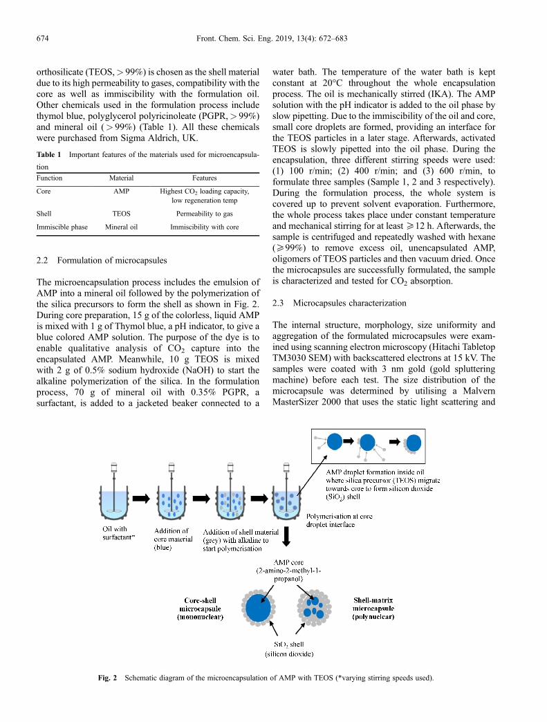
A pressure rig was set up to test the CO2 absorptionloading capacity and kinetics of the microcapsules with thepiping and instrumentation diagram (PID) is shown in theschematic diagram in Fig. 3. The sample holder in thepressure rig is a glass crucible to allow observation of thesample (quantitative analysis) from any perspective.Before exposing the sample to CO2, the pressure rigchamber is vacuumed to ensure CO2 sorption occurs whenpressure is introduced. A circulating water bath connectedto the pressure rig was used to ensure constant temperature
Fig. 3 Schematic diagram of pressure rig set-up for CO2 absorption testing (* Effective volume of pressure rig = 61 mL, includingpressure cell, connections, valves and tubings).
Sidra Rama et al. Encapsulation of 2-amino-2-methyl-1-propanol for CO2 capture 675
during the testing. A data logger records the pressure andtemperature during the experiments. Pressure is measuredby a transducer (Omega, model no: PX309-300AI) in voltswith the Data Logger which is converted to Bara for CO2
absorption calculations. At the end of the experiment, thesample was removed from the rig after depressurizing thevessel, and the sample is weighed for comparison ofweight change.For all CO2 sorption experiments with the pressure rig,
0.5�0.01 g of the sample was used. The experiments wereperformed at 10 barA initial pressure and temperatureswere maintained ranging from – 40°C to 20°C (�0.1°C).Amount of CO2 absorbed by the sample is calculated bythe pressure drop over time using Peng Robinson equationof state. To validate the data, CO2 sorption tests for eachsample were repeated at least three times. Furthermore, thecalculated values and the measured physical weightchanges between before and after CO2 exposure werecompared. The CO2 absorption system and sample loadingcapacity were considered valid only when the calculatedvalues agreed with the physically measured values within a5% error. For comparison purposes, images of the sampleswere also taken both before and after sorption.
3 Results and discussion
3.1 Formulation process and microcapsule quality
The most common precursors used for making silicondioxide are silicon alkoxides which are characterized bythe strong covalent Si–O bonding. These bonds arehydrophobic and thus immiscible with water. TEOS issuch a silica precursor. The advantage of using TEOS as aprecursor is its polymerization ability in alkaline, acidicand neutral conditions to form silicon dioxide. Duringformulation alkaline conditions were chosen due to thehigh alkalinity of the core material [18]. In this case thepolymerization of TEOS would occur through alkalinecatalyzed hydrolysis and condensation which are causedby the hydroxyl ions (OH–) of the sodium hydroxide.These OH– ions have a strong nucleophilicity and thus canattack the silicon atom. The alkoxide silicon atoms carrythe highest positive charge and are therefore the target ofthe nucleophilic attack from the deprotonated hydroxylions (OH–). This mechanism leads to the formation of a
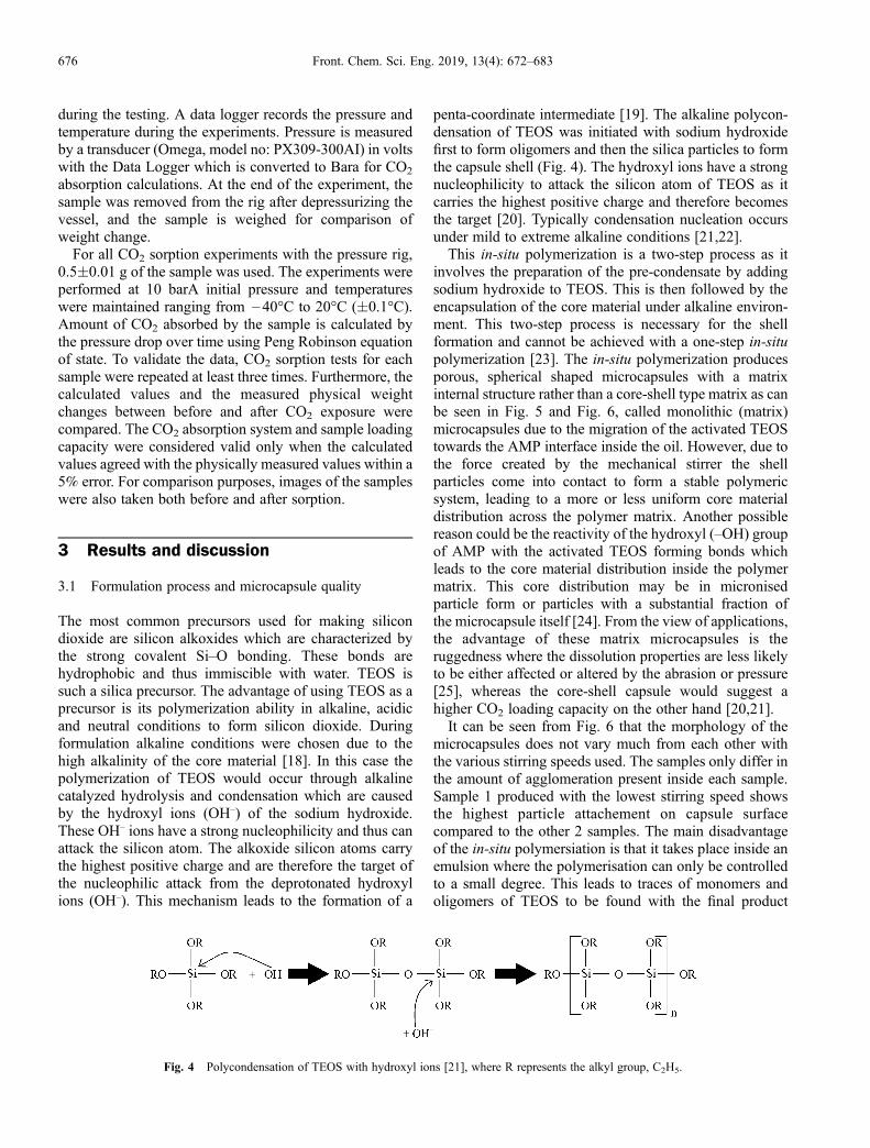
penta-coordinate intermediate [19]. The alkaline polycon-densation of TEOS was initiated with sodium hydroxidefirst to form oligomers and then the silica particles to formthe capsule shell (Fig. 4). The hydroxyl ions have a strongnucleophilicity to attack the silicon atom of TEOS as itcarries the highest positive charge and therefore becomesthe target [20]. Typically condensation nucleation occursunder mild to extreme alkaline conditions [21,22].This in-situ polymerization is a two-step process as it
involves the preparation of the pre-condensate by addingsodium hydroxide to TEOS. This is then followed by theencapsulation of the core material under alkaline environ-ment. This two-step process is necessary for the shellformation and cannot be achieved with a one-step in-situpolymerization [23]. The in-situ polymerization producesporous, spherical shaped microcapsules with a matrixinternal structure rather than a core-shell type matrix as canbe seen in Fig. 5 and Fig. 6, called monolithic (matrix)microcapsules due to the migration of the activated TEOStowards the AMP interface inside the oil. However, due tothe force created by the mechanical stirrer the shellparticles come into contact to form a stable polymericsystem, leading to a more or less uniform core materialdistribution across the polymer matrix. Another possiblereason could be the reactivity of the hydroxyl (–OH) groupof AMP with the activated TEOS forming bonds whichleads to the core material distribution inside the polymermatrix. This core distribution may be in micronisedparticle form or particles with a substantial fraction ofthe microcapsule itself [24]. From the view of applications,the advantage of these matrix microcapsules is theruggedness where the dissolution properties are less likelyto be either affected or altered by the abrasion or pressure[25], whereas the core-shell capsule would suggest ahigher CO2 loading capacity on the other hand [20,21].It can be seen from Fig. 6 that the morphology of the
microcapsules does not vary much from each other withthe various stirring speeds used. The samples only differ inthe amount of agglomeration present inside each sample.Sample 1 produced with the lowest stirring speed showsthe highest particle attachement on capsule surfacecompared to the other 2 samples. The main disadvantageof the in-situ polymersiation is that it takes place inside anemulsion where the polymerisation can only be controlledto a small degree. This leads to traces of monomers andoligomers of TEOS to be found with the final product
Fig. 4 Polycondensation of TEOS with hydroxyl ions [21], where R represents the alkyl group, C2H5.
676 Front. Chem. Sci. Eng. 2019, 13(4): 672–683
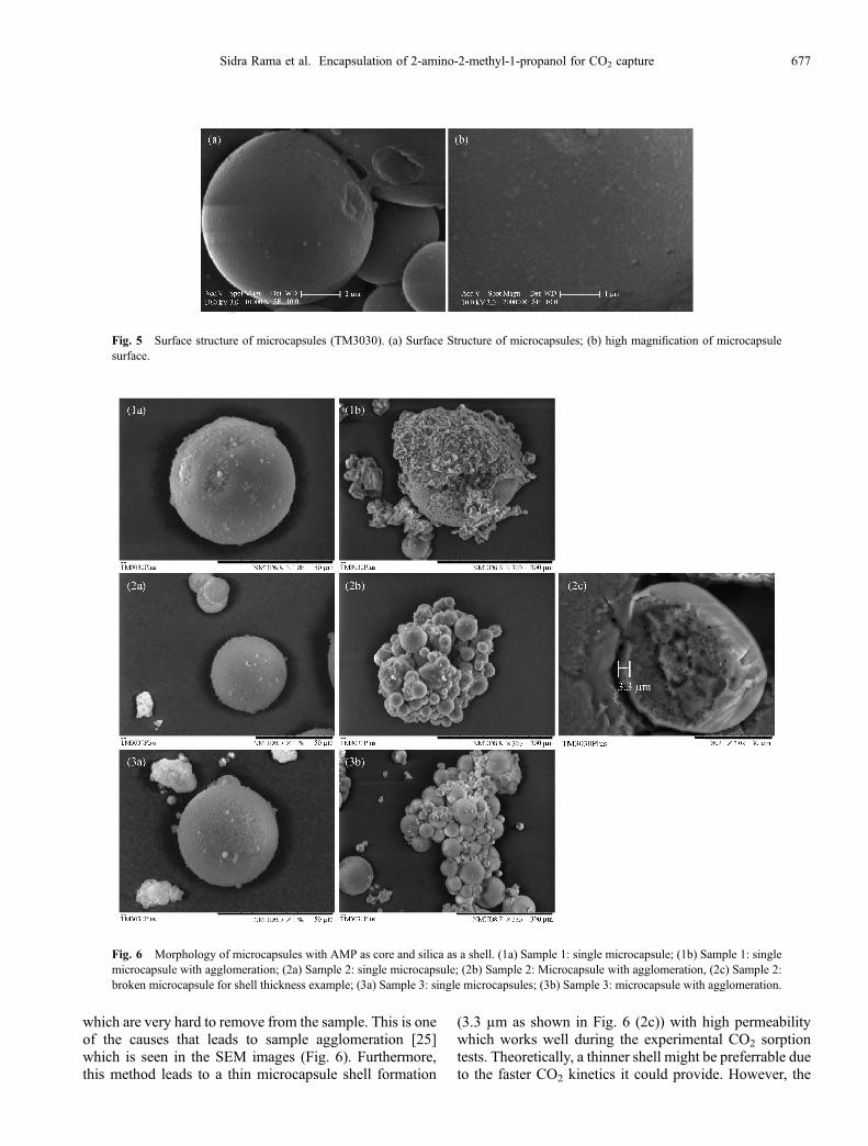
which are very hard to remove from the sample. This is oneof the causes that leads to sample agglomeration [25]which is seen in the SEM images (Fig. 6). Furthermore,this method leads to a thin microcapsule shell formation
(3.3 µm as shown in Fig. 6 (2c)) with high permeabilitywhich works well during the experimental CO2 sorptiontests. Theoretically, a thinner shell might be preferrable dueto the faster CO2 kinetics it could provide. However, the
Fig. 5 Surface structure of microcapsules (TM3030). (a) Surface Structure of microcapsules; (b) high magnification of microcapsulesurface.
Fig. 6 Morphology of microcapsules with AMP as core and silica as a shell. (1a) Sample 1: single microcapsule; (1b) Sample 1: singlemicrocapsule with agglomeration; (2a) Sample 2: single microcapsule; (2b) Sample 2: Microcapsule with agglomeration, (2c) Sample 2:broken microcapsule for shell thickness example; (3a) Sample 3: single microcapsules; (3b) Sample 3: microcapsule with agglomeration.
Sidra Rama et al. Encapsulation of 2-amino-2-methyl-1-propanol for CO2 capture 677
CO2 absorption results presented in the present workdemonstrate a right balance between sorption kinetics andshell thickness as would be discussed in the following.Surface area (SA) and pore size are both important
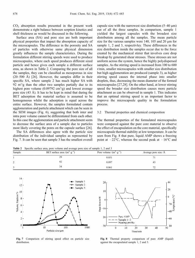
physical properties that impact the absorption capacity ofthe microcapsules. The difference in the porosity and SAof particles with otherwise same physical dimensiongreatly influences the sample characteristics. During theformulation different stirring speeds were used to producemicrocapsules, where each speed produces different sizedparticle and hence gives each sample a different surfaceerea, as shown in Table 2. Comparing the pore size of allthe samples, they can be classified as mesoporous in size(20–500 Å) [26]. However, the samples differ in theirspecific SA, where sample 2 has much higher SA with92 m2/g than the other two samples partially due to itshighest pore volume (0.09792 cm3/g) and lowest averagepore size (43 Å). It has to be kept in mind that during theBET adsorption the material surface is assumed to behomogeneous whilst the adsorption is equal across theentire surface. However, the samples formulated containagglomeration and particle attachment which can be seen inthe SEM images (Fig. 6), suggesting that both inter andintra pore volume cannot be differentiated from each other.In this case the agglomeration and particle attachment seemto decrease the surface area of a sample due to particlesmost likely covering the pores on the capsule surface [26].The SA differences also agree with the particle size
distribution of the individual samples as represented byFig. 7. It can be seen that sample 3 has the smallest overall
capsule size with the narrowest size distrbution (5–40 mm)out of all the three samples. In comparison, sample 1yielded the largest capsules with the broadest sizedistribution among all the samples. The mean particlesize for the various samples were 140, 105 and 20 µm forsample 1, 2 and 3, respectivley. These differences in thesize distribution inside the samples occur due to the forcecreated by the mechanical stirrer that involves core dropbreakup by generated shear stresses. These stresses are notuniform across the system, hence the highly polydispersedsamples. As the stirring speed is increased from 100 to 600r/min, smaller microcapsules with smaller size distributionbut high agglomeration are produced (sample 3), as higherstirring speed causes the internal phase into smallerdroplets, thus, decreasing the mean diameter of the formedmicrocapsules [27,28]. On the other hand, at lower stirringspeed the broader size distribution causes more particleattachment as can be observed in sample 1. This indicatesthat an optimal stirring speed is an important factor toimprove the microcapsule quality in the formulationprocess.
3.2 Thermal properties and chemical composition
The thermal properties of the formulated microcapsuleswere compared against the pure core material to observethe effect of encapsulation on the core material, specificallymicrocapsule thermal stability at low temperature. It can beseen from Fig. 8 that pure, liquid AMP shows a freezingpoint at – 22°C, whereas the second peak at – 16°C and
Table 2 Specific surface area, pore volume and average pore size of sample 1, 2 and 3
Sample BET surface area /(m2$g–1) Pore volume /(m2$g–1) Average pore size /Å
1 29 0.051 71
2 92 0.097 43
3 34 0.061 72
Fig. 7 Comparison of stirring speed effect on particle sizedistribution.
Fig. 8 Thermal property comparison of pure AMP (liquid)against the encapsulated sample 1, 2 and 3.
678 Front. Chem. Sci. Eng. 2019, 13(4): 672–683

the third one at 8°C representing the recrystallisation andmelting respectively. It is worth mentioning that nofreezing point has been stated in literature to the best ofour knowledge for AMP; only a melting temperature of30°C–31°C [29]. However, according to the DSC result(Fig. 8) for pure, liquid AMP the freezing point seems to bearound – 22°C, suggesting the material undergoes crystal-lization at this point. The endothermic peak (melting ofmaterial) around 8°C is also not found in literature which isexplained by the re-melting of the AMP from thecrystalline state that shifts the melting point of the materialto a lower temperature. These results suggest possiblechanges in material properties compared to pure, liquidcore.In comparison, no melting or freezing is observed with
encapsulated samples irrespective of their stirring speed,indicating good thermal stability over the range of 25°C to– 60°C which is supported by the findings of the SEMimages (Fig. 9). The thermal cycling of all three samplesshow no change in morphology after ten continuouscycling of 20°C to – 100°C which was carried out with adilatometer. These results indicate that all producedmicrocapsules irrespective of their stirring speed canwithstand very low temperature whilst still being able toretain their shape after intensive, low temperatureexposure, though some microcapsules occasionally doshow cracks and dents.The chemical composition analysis of the formulated
microcapsules was carried out using FTIR, indicatingpossible amine reacting during polymerization and as aresult the creation of new bonds as well as the decrease ofcore concentration. It can be seen from Fig. 10 that thepure, liquid core material (AMP) has an overall higher IRtransmittance compared to the encapsulated sample, this isespecially the case for 3000–3500 cm–1 IR spectra range.The primary interest in the FTIR spectra is the N–H bondsfrom the amine groups and the O–H bonds from thepropanol groups. Both the N–H bonds and the O–H bondare present in the FTIR spectra (Fig. 10) in the range of3500–3200 cm–1, making it harder to distinguish betweenthe two bonds as they have overlapping infraredtransmittance absorbance. However, the bimodal nature
of the first two peaks, suggests the presence of primaryamines whereas the third peak suggests the hydroxyl group[30]. The N–H bond stretch transmittance in the range of3250 to 3650 cm–1 decreases after encapsulation, which issuggesting a reduction in the free AMP due to polymerisa-tion reaction between the amine and shell material [30].This reduction in AMP is not favorable because it wouldaffect the CO2 absorption as less AMP is available to reactwith CO2 to form carbamate ions. However, the mostlikely reason for the reduced peaks compared to the pureliquid AMP is due to a lower amount of the encapsulatedsolvent. Though there is the possibility of in-situpolymerisation of the amine group from AMP [31],amine and the hydroxyl group (–OH) both have the sameprobability of providing the required hydrogen for theformation of the shell material.
3.3 CO2 Absorption
Samples exposed to CO2 undergo a color change from blueto yellow which is shown in Fig. 11 suggests carbamateformation [32,33] and provides evidence of successfulCO2 absorption by the samples. The change in color occursdue to the presence of Thymol Blue inside the micro-capsules. This method of visual CO2 absorption has alsobeen used by Aines et al. [34] where sample color changedwhen up to ~90% of maximum carbon uptake reached.This visible color enables qualitative evaluation of the CO2
absorption and desorption capacity of microcapsules. ThepH of the sample before testing was> 10 due to highalkalinity of AMP but drops to< 6 after the absorption ascarbamate ions are formed while hydrogen ions arereleased [32]. This chemical absorption process is a widelyknown method and is under consideration for an industrialscale CO2 capture system [35].Moreover, this carbamate reaction is reversible as shown
in Fig. 12. The thermal regeneration heat requirement isdependent on the energy required to break the bonds thatwere created during the CO2 absorption. The lower therequired energy, the lower the energy-intensive CO2
release process [35,36]. In our case when the micro-capsules are heated up to 40°C slightly higher than the
Fig. 9 Microcapsule morphology after ten continuous cycling. (a) Sample 1: microcapsule with crack and dents; (b) Sample 2:microcapsules with dents; (c) Sample 3: microcapsule with dents.
Sidra Rama et al. Encapsulation of 2-amino-2-methyl-1-propanol for CO2 capture 679
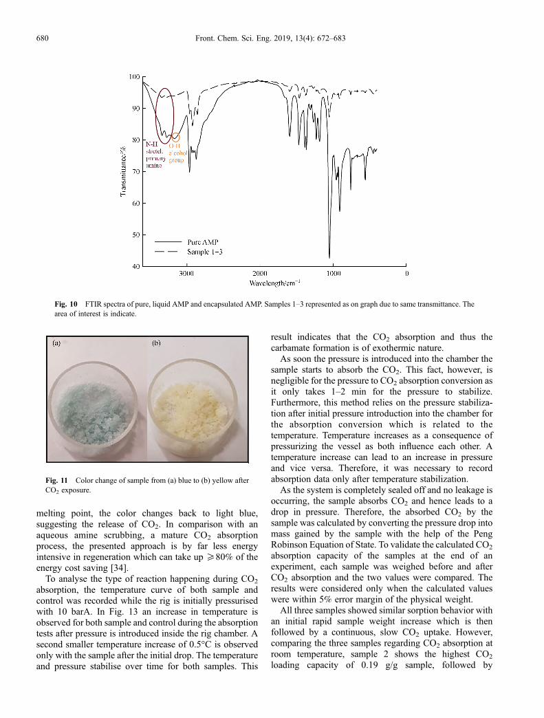
melting point, the color changes back to light blue,suggesting the release of CO2. In comparison with anaqueous amine scrubbing, a mature CO2 absorptionprocess, the presented approach is by far less energyintensive in regeneration which can take up ≥80% of theenergy cost saving [34].To analyse the type of reaction happening during CO2
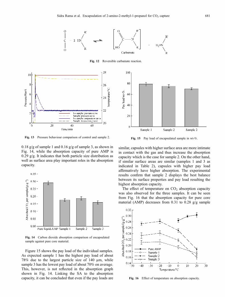
absorption, the temperature curve of both sample andcontrol was recorded while the rig is initially pressurisedwith 10 barA. In Fig. 13 an increase in temperature isobserved for both sample and control during the absorptiontests after pressure is introduced inside the rig chamber. Asecond smaller temperature increase of 0.5°C is observedonly with the sample after the initial drop. The temperatureand pressure stabilise over time for both samples. This
result indicates that the CO2 absorption and thus thecarbamate formation is of exothermic nature.As soon the pressure is introduced into the chamber the
sample starts to absorb the CO2. This fact, however, isnegligible for the pressure to CO2 absorption conversion asit only takes 1–2 min for the pressure to stabilize.Furthermore, this method relies on the pressure stabiliza-tion after initial pressure introduction into the chamber forthe absorption conversion which is related to thetemperature. Temperature increases as a consequence ofpressurizing the vessel as both influence each other. Atemperature increase can lead to an increase in pressureand vice versa. Therefore, it was necessary to recordabsorption data only after temperature stabilization.As the system is completely sealed off and no leakage is
occurring, the sample absorbs CO2 and hence leads to adrop in pressure. Therefore, the absorbed CO2 by thesample was calculated by converting the pressure drop intomass gained by the sample with the help of the PengRobinson Equation of State. To validate the calculated CO2
absorption capacity of the samples at the end of anexperiment, each sample was weighed before and afterCO2 absorption and the two values were compared. Theresults were considered only when the calculated valueswere within 5% error margin of the physical weight.All three samples showed similar sorption behavior with
an initial rapid sample weight increase which is thenfollowed by a continuous, slow CO2 uptake. However,comparing the three samples regarding CO2 absorption atroom temperature, sample 2 shows the highest CO2
loading capacity of 0.19 g/g sample, followed by
Fig. 10 FTIR spectra of pure, liquid AMP and encapsulated AMP. Samples 1–3 represented as on graph due to same transmittance. Thearea of interest is indicate.
Fig. 11 Color change of sample from (a) blue to (b) yellow afterCO2 exposure.
680 Front. Chem. Sci. Eng. 2019, 13(4): 672–683
0.18 g/g of sample 1 and 0.16 g/g of sample 3, as shown inFig. 14, while the absorption capacity of pure AMP is0.29 g/g. It indicates that both particle size distribution aswell as surface area play important roles in the absorptioncapacity.
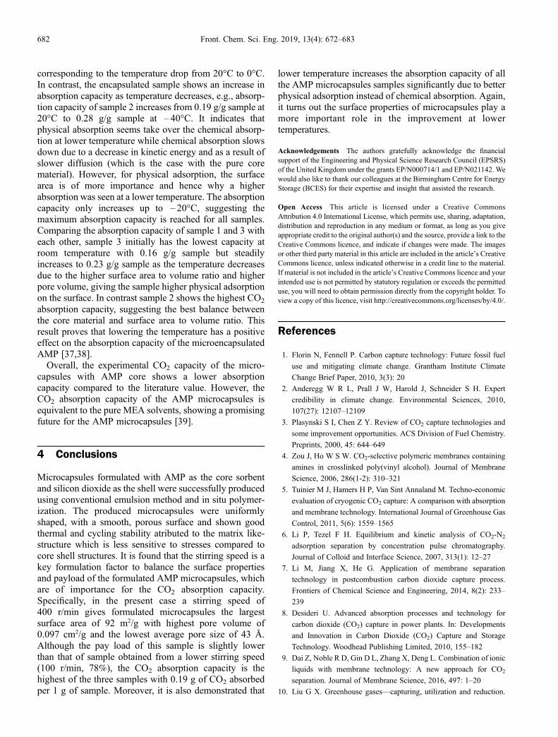
Figure 15 shows the pay load of the individual samples.As expected sample 1 has the highest pay load of about78% due to the largest particle size of 140 µm, whilesample 3 has the lowest pay load of about 70% on average.This, however, is not reflected in the absorption graphshown in Fig. 14. Linking the SA to the absorptioncapacity, it can be concluded that even if the pay loads are
similar, capsules with higher surface area are more intimatein contact with the gas and thus increase the absorptioncapacity which is the case for sample 2. On the other hand,if similar surface areas are similar (samples 1 and 3 asindicated in Table 2), capsules with higher pay loadaffirmatively have higher absorption. The experimentalresults confirm that sample 2 displays the best balancebetween its surface properties and pay load resulting thehighest absorption capacity.The effect of temperature on CO2 absorption capacity
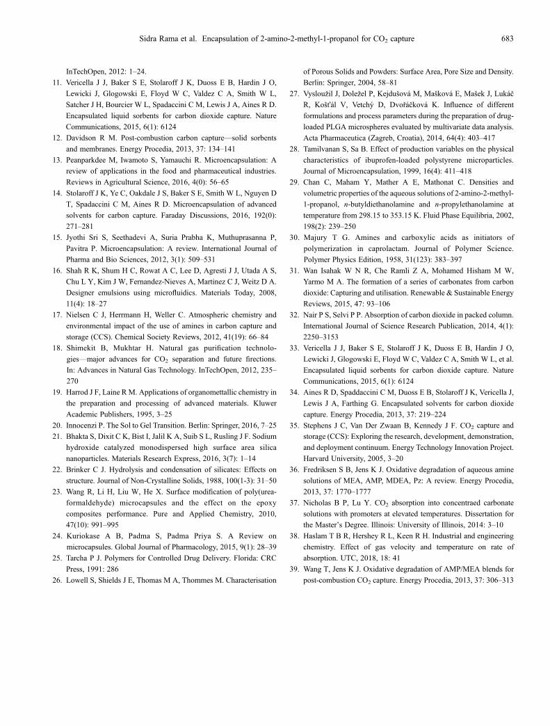
was also observed for the three samples. It can be seenfrom Fig. 16 that the absorption capacity for pure corematerial (AMP) decreases from 0.31 to 0.28 g/g sample
Fig. 12 Reversible carbamate reaction.
Fig. 13 Pressure behaviour comparison of control and sample 2.
Fig. 14 Carbon dioxide absorption comparison of encapsulatedsample against pure core material.
Fig. 15 Pay load of encapsulated sample in wt-%.
Fig. 16 Effect of temperature on absorption capacity.
Sidra Rama et al. Encapsulation of 2-amino-2-methyl-1-propanol for CO2 capture 681
corresponding to the temperature drop from 20°C to 0°C.In contrast, the encapsulated sample shows an increase inabsorption capacity as temperature decreases, e.g., absorp-tion capacity of sample 2 increases from 0.19 g/g sample at20°C to 0.28 g/g sample at – 40°C. It indicates thatphysical absorption seems take over the chemical absorp-tion at lower temperature while chemical absorption slowsdown due to a decrease in kinetic energy and as a result ofslower diffusion (which is the case with the pure corematerial). However, for physical adsorption, the surfacearea is of more importance and hence why a higherabsorption was seen at a lower temperature. The absorptioncapacity only increases up to – 20°C, suggesting themaximum absorption capacity is reached for all samples.Comparing the absorption capacity of sample 1 and 3 witheach other, sample 3 initially has the lowest capacity atroom temperature with 0.16 g/g sample but steadilyincreases to 0.23 g/g sample as the temperature decreasesdue to the higher surface area to volume ratio and higherpore volume, giving the sample higher physical adsorptionon the surface. In contrast sample 2 shows the highest CO2
absorption capacity, suggesting the best balance betweenthe core material and surface area to volume ratio. Thisresult proves that lowering the temperature has a positiveeffect on the absorption capacity of the microencapsulatedAMP [37,38].Overall, the experimental CO2 capacity of the micro-
capsules with AMP core shows a lower absorptioncapacity compared to the literature value. However, theCO2 absorption capacity of the AMP microcapsules isequivalent to the pure MEA solvents, showing a promisingfuture for the AMP microcapsules [39].
4 Conclusions
Microcapsules formulated with AMP as the core sorbentand silicon dioxide as the shell were successfully producedusing conventional emulsion method and in situ polymer-ization. The produced microcapsules were uniformlyshaped, with a smooth, porous surface and shown goodthermal and cycling stability atributed to the matrix like-structure which is less sensitive to stresses compared tocore shell structures. It is found that the stirring speed is akey formulation factor to balance the surface propertiesand payload of the formulated AMP microcapsules, whichare of importance for the CO2 absorption capacity.Specifically, in the present case a stirring speed of400 r/min gives formulated microcapsules the largestsurface area of 92 m2/g with highest pore volume of0.097 cm2/g and the lowest average pore size of 43 Å.Although the pay load of this sample is slightly lowerthan that of sample obtained from a lower stirring speed(100 r/min, 78%), the CO2 absorption capacity is thehighest of the three samples with 0.19 g of CO2 absorbedper 1 g of sample. Moreover, it is also demonstrated that
lower temperature increases the absorption capacity of allthe AMP microcapsules samples significantly due to betterphysical adsorption instead of chemical absorption. Again,it turns out the surface properties of microcapsules play amore important role in the improvement at lowertemperatures.
Acknowledgements The authors gratefully acknowledge the financialsupport of the Engineering and Physical Science Research Council (EPSRS)of the United Kingdom under the grants EP/N000714/1 and EP/N021142. Wewould also like to thank our colleagues at the Birmingham Centre for EnergyStorage (BCES) for their expertise and insight that assisted the research.
Open Access This article is licensed under a Creative CommonsAttribution 4.0 International License, which permits use, sharing, adaptation,distribution and reproduction in any medium or format, as long as you giveappropriate credit to the original author(s) and the source, provide a link to theCreative Commons licence, and indicate if changes were made. The imagesor other third party material in this article are included in the article’s CreativeCommons licence, unless indicated otherwise in a credit line to the material.If material is not included in the article’s Creative Commons licence and yourintended use is not permitted by statutory regulation or exceeds the permitteduse, you will need to obtain permission directly from the copyright holder. Toview a copy of this licence, visit http://creativecommons.org/licenses/by/4.0/.
References
1. Florin N, Fennell P. Carbon capture technology: Future fossil fuel
use and mitigating climate change. Grantham Institute Climate
Change Brief Paper, 2010, 3(3): 20
2. Anderegg W R L, Prall J W, Harold J, Schneider S H. Expert
credibility in climate change. Environmental Sciences, 2010,
107(27): 12107–12109
3. Plasynski S I, Chen Z Y. Review of CO2 capture technologies and
some improvement opportunities. ACS Division of Fuel Chemistry.
Preprints, 2000, 45: 644–649
4. Zou J, Ho W S W. CO2-selective polymeric membranes containing
amines in crosslinked poly(vinyl alcohol). Journal of Membrane
Science, 2006, 286(1-2): 310–321
5. Tuinier M J, Hamers H P, Van Sint Annaland M. Techno-economic
evaluation of cryogenic CO2 capture: A comparison with absorption
and membrane technology. International Journal of Greenhouse Gas
Control, 2011, 5(6): 1559–1565
6. Li P, Tezel F H. Equilibrium and kinetic analysis of CO2-N2
adsorption separation by concentration pulse chromatography.
Journal of Colloid and Interface Science, 2007, 313(1): 12–27
7. Li M, Jiang X, He G. Application of membrane separation
technology in postcombustion carbon dioxide capture process.
Frontiers of Chemical Science and Engineering, 2014, 8(2): 233–
239
8. Desideri U. Advanced absorption processes and technology for
carbon dioxide (CO2) capture in power plants. In: Developments
and Innovation in Carbon Dioxide (CO2) Capture and Storage
Technology. Woodhead Publishing Limited, 2010, 155–182
9. Dai Z, Noble R D, Gin D L, Zhang X, Deng L. Combination of ionic
liquids with membrane technology: A new approach for CO2
separation. Journal of Membrane Science, 2016, 497: 1–20
10. Liu G X. Greenhouse gases—capturing, utilization and reduction.
682 Front. Chem. Sci. Eng. 2019, 13(4): 672–683
InTechOpen, 2012: 1–24.
11. Vericella J J, Baker S E, Stolaroff J K, Duoss E B, Hardin J O,
Lewicki J, Glogowski E, Floyd W C, Valdez C A, Smith W L,
Satcher J H, Bourcier W L, Spadaccini C M, Lewis J A, Aines R D.
Encapsulated liquid sorbents for carbon dioxide capture. Nature
Communications, 2015, 6(1): 6124
12. Davidson R M. Post-combustion carbon capture—solid sorbents
and membranes. Energy Procedia, 2013, 37: 134–141
13. Peanparkdee M, Iwamoto S, Yamauchi R. Microencapsulation: A
review of applications in the food and pharmaceutical industries.
Reviews in Agricultural Science, 2016, 4(0): 56–65
14. Stolaroff J K, Ye C, Oakdale J S, Baker S E, Smith W L, Nguyen D
T, Spadaccini C M, Aines R D. Microencapsulation of advanced
solvents for carbon capture. Faraday Discussions, 2016, 192(0):
271–281
15. Jyothi Sri S, Seethadevi A, Suria Prabha K, Muthuprasanna P,
Pavitra P. Microencapsulation: A review. International Journal of
Pharma and Bio Sciences, 2012, 3(1): 509–531
16. Shah R K, Shum H C, Rowat A C, Lee D, Agresti J J, Utada A S,
Chu L Y, Kim J W, Fernandez-Nieves A, Martinez C J, Weitz D A.
Designer emulsions using microfluidics. Materials Today, 2008,
11(4): 18–27
17. Nielsen C J, Herrmann H, Weller C. Atmospheric chemistry and
environmental impact of the use of amines in carbon capture and
storage (CCS). Chemical Society Reviews, 2012, 41(19): 66–84
18. Shimekit B, Mukhtar H. Natural gas purification technolo-
gies—major advances for CO2 separation and future firections.
In: Advances in Natural Gas Technology. InTechOpen, 2012, 235–
270
19. Harrod J F, Laine RM. Applications of organomettallic chemistry in
the preparation and processing of advanced materials. Kluwer
Academic Publishers, 1995, 3–25
20. Innocenzi P. The Sol to Gel Transition. Berlin: Springer, 2016, 7–25
21. Bhakta S, Dixit C K, Bist I, Jalil K A, Suib S L, Rusling J F. Sodium
hydroxide catalyzed monodispersed high surface area silica
nanoparticles. Materials Research Express, 2016, 3(7): 1–14
22. Brinker C J. Hydrolysis and condensation of silicates: Effects on
structure. Journal of Non-Crystalline Solids, 1988, 100(1-3): 31–50
23. Wang R, Li H, Liu W, He X. Surface modification of poly(urea-
formaldehyde) microcapsules and the effect on the epoxy
composites performance. Pure and Applied Chemistry, 2010,
47(10): 991–995
24. Kuriokase A B, Padma S, Padma Priya S. A Review on
microcapsules. Global Journal of Pharmacology, 2015, 9(1): 28–39
25. Tarcha P J. Polymers for Controlled Drug Delivery. Florida: CRC
Press, 1991: 286
26. Lowell S, Shields J E, Thomas M A, Thommes M. Characterisation
of Porous Solids and Powders: Surface Area, Pore Size and Density.
Berlin: Springer, 2004, 58–81
27. Vysloužil J, Doležel P, Kejdušová M, Mašková E, Mašek J, LukáčR, Košťál V, Vetchý D, Dvořáčková K. Influence of different
formulations and process parameters during the preparation of drug-
loaded PLGA microspheres evaluated by multivariate data analysis.
Acta Pharmaceutica (Zagreb, Croatia), 2014, 64(4): 403–417
28. Tamilvanan S, Sa B. Effect of production variables on the physical
characteristics of ibuprofen-loaded polystyrene microparticles.
Journal of Microencapsulation, 1999, 16(4): 411–418
29. Chan C, Maham Y, Mather A E, Mathonat C. Densities and
volumetric properties of the aqueous solutions of 2-amino-2-methyl-
1-propanol, n-butyldiethanolamine and n-propylethanolamine at
temperature from 298.15 to 353.15 K. Fluid Phase Equilibria, 2002,
198(2): 239–250
30. Majury T G. Amines and carboxylic acids as initiators of
polymerization in caprolactam. Journal of Polymer Science.
Polymer Physics Edition, 1958, 31(123): 383–397
31. Wan Isahak W N R, Che Ramli Z A, Mohamed Hisham M W,
Yarmo M A. The formation of a series of carbonates from carbon
dioxide: Capturing and utilisation. Renewable & Sustainable Energy
Reviews, 2015, 47: 93–106
32. Nair P S, Selvi P P. Absorption of carbon dioxide in packed column.
International Journal of Science Research Publication, 2014, 4(1):
2250–3153
33. Vericella J J, Baker S E, Stolaroff J K, Duoss E B, Hardin J O,
Lewicki J, Glogowski E, Floyd W C, Valdez C A, Smith W L, et al.
Encapsulated liquid sorbents for carbon dioxide capture. Nature
Communications, 2015, 6(1): 6124
34. Aines R D, Spaddaccini C M, Duoss E B, Stolaroff J K, Vericella J,
Lewis J A, Farthing G. Encapsulated solvents for carbon dioxide
capture. Energy Procedia, 2013, 37: 219–224
35. Stephens J C, Van Der Zwaan B, Kennedy J F. CO2 capture and
storage (CCS): Exploring the research, development, demonstration,
and deployment continuum. Energy Technology Innovation Project.
Harvard University, 2005, 3–20
36. Fredriksen S B, Jens K J. Oxidative degradation of aqueous amine
solutions of MEA, AMP, MDEA, Pz: A review. Energy Procedia,
2013, 37: 1770–1777
37. Nicholas B P, Lu Y. CO2 absorption into concentraed carbonate
solutions with promoters at elevated temperatures. Dissertation for
the Master’s Degree. Illinois: University of Illinois, 2014: 3–10
38. Haslam T B R, Hershey R L, Keen R H. Industrial and engineering
chemistry. Effect of gas velocity and temperature on rate of
absorption. UTC, 2018, 18: 41
39. Wang T, Jens K J. Oxidative degradation of AMP/MEA blends for
post-combustion CO2 capture. Energy Procedia, 2013, 37: 306–313
Sidra Rama et al. Encapsulation of 2-amino-2-methyl-1-propanol for CO2 capture 683