effects of carbon nanotubes on flame spread rate over 1-propanol
TRANSCRIPT
ARTICLE IN PRESS
Fire Safety Journal 40 (2005) 425–438
0379-7112/$ -
doi:10.1016/j
�CorrespoE-mail ad
www.elsevier.com/locate/firesaf
Effects of carbon nanotubes onflame spread rate over 1-propanol
Mohamed I. Hassana, Eric Grulkeb,Keng Chuaha, Kozo Saitoa,�
aMechanical Engineering Department, University of Kentucky, Lexington, KY 40506-0503, USAbChemical & Materials Engineering Department, University of Kentucky, Lexington, KY 40506-0503, USA
Received 2 August 2004; received in revised form 5 January 2005; accepted 8 February 2005
Available online 9 June 2005
Abstract
This paper discusses the potential for thermally conductive nanoparticles to reduce flame
spread velocities over fuel dispersion mixtures. Multi-walled carbon nanotubes (MWNTs)
were dispersed in 1-propanol at levels above the mixture’s percolation limit, 0.5, 1.0, 2.0, 4, 8,
and 12 wt%, and tested in a rectangular fuel tray and a shallow pan flame spread system. The
MWNTs/1-propanol mixtures had much lower flame spread rates than the original fuel itself
at temperatures below 1-propanol’s flash point. A 2 wt% MWNT loading reduced the flame
spread rate to 9–15% of the neat fuel rate (the corresponding increase in the average flame
spreading time over a 16 cm horizontal test length is approximately 6–11 times) and
significantly inhibited the pulsating flame spread behavior. Flame spread rate was calculated
for both the pure fuel and MWNT mixtures with a surface-tension-driven spread rate
equation. The calculations favorably compare with corresponding measured values despite
several assumptions made. Thermally conductive high aspect ratio nanoparticles could be
effective flame spread suppressants for liquid fuels.
r 2005 Elsevier Ltd. All rights reserved.
Keywords: Flame spread; Carbon nanotubes; Liquid fuel
see front matter r 2005 Elsevier Ltd. All rights reserved.
.firesaf.2005.02.007
nding author.
dress: [email protected] (K. Saito).
ARTICLE IN PRESS
M.I. Hassan et al. / Fire Safety Journal 40 (2005) 425–438426
1. Introduction
Flame spread over liquids is an important research topic related to fire hazards inliquid fuel storage tanks, and automobile and airplane crash accidents. Previously aseries of experimental work using a rectangular tray with a large aspect ratio wereconducted and results from those studies were published elsewhere [1–6]. Wellsummarized reviews addressing progress on flame spread research are also available[7–9]. One of the major findings from these studies showed that the flame-inducedliquid flow plays an important role in flame spread over liquid when the initial liquidtemperature is under its flash point [1–9]. When the initial liquid temperature isabove the flash point, the liquid fuel generates sufficient vapor pressure to satisfy thelean flammability limit through which the flame front can spread in the gas phase,becoming a gas phase flame spread mechanism without involving the liquid phase.
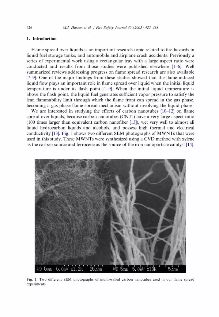
We are interested in studying the effects of carbon nanotubes [10–12] on flamespread over liquids, because carbon nanotubes (CNTs) have a very large aspect ratio(100 times larger than equivalent carbon nanofiber [13]), wet very well to almost allliquid hydrocarbon liquids and alcohols, and possess high thermal and electricalconductivity [13]. Fig. 1 shows two different SEM photographs of MWNTs that wereused in this study. These MWNTs were synthesized using a CVD method with xyleneas the carbon source and ferrocene as the source of the iron nanoparticle catalyst [14].
Fig. 1. Two different SEM photographs of multi-walled carbon nanotubes used in our flame spread
experiments.

ARTICLE IN PRESS
M.I. Hassan et al. / Fire Safety Journal 40 (2005) 425–438 427
The microphotograph on the left shows the typical reactor product as harvested fromthe reactor: the nanotubes (�50mm in length) grow perpendicular to the reactorsurface and are moderately entangled. The image on the right shows that the typicaldiameter is �250nm or less. Nanotubes produced [14] have been used in a number ofapplications (including structural polymer nanocomposites, fire-retardant additives forpolymers [15], and electrically and thermally conductive polymers and fluids).
We expect carbon nanotube dispersions either to effectively interfere with theflame-induced liquid flow or to conduct heat from the fluid surface, in either caseretarding flame spread behavior. We added small amount of MWNTs to 1-propanoland created six different MWNT wt% in 1-propanol mixtures to study its effect onflame spread. The rectangular fuel tray of our previous experiments [16,17] was used;spread rate, pulsation frequency, and gas phase temperature distribution near theflame leading edge were measured. In addition to the rectangular tray, we also used ashallow pan to conduct ignition tests.
2. Why do CNTs have effects on flame spread?
The flame-generated liquid flow can be modified by two mechanisms. A three-dimensional porous solid can dampen and inhibit fluid circulation in the liquid, reducingthe velocities of sub-surface liquid circulation. Also, a solid with high thermalconductivity relative to the fuel can transport energy away from the fluid surface. Thissecond mechanism is thought to be the predominant factor in significantly reducing theheat release rate when MWNTs/polymer nanocomposites are burned in conventionalcone calorimeter tests [15]. Such materials keep the fluid near the flame front cooler thannormal, while providing more heating to the fluid directly underneath the flame. Thedampening of liquid phase velocities would depend primarily on the pressure dropthrough the 3-D solid network as a function of velocities, which would probably followan Ergun-type equation. The energy flux transported by the solid into the fluid woulddepend on its absorptivity, emissivity, conductivity, and local volume fraction, andwould depend on the network being above the percolation limit of the particular particlemorphology. Glassman and Dryer [7] and Ito et al. [6] separately tested the firstmechanism, while the second mechanism has not been explored.
Nanoparticles of highly conductive solids, such as exfoliated clays and carbonnanotubes [15], can reduce the rate of heat release of polymer solids in cone calorimetertests through similar mechanisms associated with rapid heat conduction in thecondensed phase. High aspect ratio MWNTs are known to form stable 3-D networks,can be dispersed in liquids, and have high thermal conductivities relative to liquid fuels.
3. Experimental methods
We employed a rectangular tray shown in Fig. 2b for flame spread test and ashallow pan shown in Fig. 2c for ignition tests. The rectangular tray was used byother researchers [1–5,7–9] and our group [6,16,17] to study flame spread over

ARTICLE IN PRESS
Fig. 2. (a) Typical video captured photographs of advancing flame front at uniform time intervals, 0.34 s
(0.5 wt% MWNTs in 1-propanol and the initial 1-propanol temperature 12.5 1C). (b) Rectangular flame
spread tray with IR and CCD camera setups. (c) A Pyrex made shallow pan used for ignition tests.
M.I. Hassan et al. / Fire Safety Journal 40 (2005) 425–438428
liquids, and it has been accepted as a standard apparatus to study flame spread overliquids because it can generate semi 2-D thermal and fluid dynamic structures whichare suitable for accurate measurements. The tray (2 cm wide, 30 cm long, and 1 cmdeep) has Pyrex sidewalls and a PMMA bottom. A laboratory refrigerator is used tocool the fuel to a temperature lower than the initial liquid temperature for each test.Two type K thermocouples, whose wire diameter is both 100 mm, are used (one in the

ARTICLE IN PRESS
M.I. Hassan et al. / Fire Safety Journal 40 (2005) 425–438 429
middle and the other on the liquid surface) to check the liquid temperature beforeignition. A pilot-flame igniter was used to ignite the flame from one end of the tray.If the fuel temperature was below the flash point, the advancing flame created by theigniter must heat the fuel ahead of the flame leading edge to the flash point. Theflame was extinguished when it had spread over the entire tray. No combustion ofthe MWNTs occurred under these experimental conditions.
For ignition tests, however, a shallow pan shown in Fig. 2c was used to minimizean immediate side wall effect of the rectangular tray apparatus. NASA researchers[18] used a shallow pan for their early flame spread experiments, but later theyswitched to a rectangular narrow tray due to liquid surface waves created during theflame spread across the shallow pan surface, resulting in liquid instabilities that weredifficult to control to establish repeatable data. We added this shallow panexperiment to determine the effects of side walls, because some MWNTs areattracted to the side wall.
For both experiments, 1-propanol was used as the base fuel because it waswidely used in flame spread studies [6,16,17]. 1-propanol was loaded with variouslevels of MWNTs. To obtain an accurate flame spread measurement technique,flame spread was preliminary measured by both a CCD digital video camera (theimage resolution of 780� 1024 pixcels) and IR digital video camera (the imageresolution of 250� 250 pixcels), both at 30 fps. By comparing both results, weidentified that the IR side view image was sharper than the CCD image for locatingthe temporal positions of spreading flame and observing detail thermal structure ofthe flame. The CCD video image taken from top was also found useful in recordingliquid surface flow, which can help us to interpret the importance of this mechanismwith addition of MWNTs to the fuel. Therefore, we operated both cameras duringexperiments.
For the flame spread measurement, we carefully compared the IR image with thethermocouple temperature and matched the maximum flame front temperaturelocation with a specific IR color. By individually tracing the IR image fromthe recorded video, flame spread rates can be accurately measured by tracking theflame location vs. time with a MatLab subroutine. The frames were stored on acomputer and were saved as a sequence of images using the software of the IRcamera. The image resolution of the IR camera was sufficient to show significantdetails for the flame spread (see Fig. 2a).
For flame spread over sub-flash point liquids, three different types of flame spreadcan be observed: uniform, pulsating and pseudo-uniform as the initial fueltemperature decreases [1]. For 1-propanol, flame pulsation occurred with its initialfuel temperature at between 10 and 18 1C, and with an increase in the fueltemperature beyond 18 1C up to the flash point (25 1C), flame spread pattern becameuniform. We varied the initial fuel temperature between 10 and 18 1C and studied theeffect of MWNTs on flame spread rates. Then more detailed experiments wereconducted for the initial fuel temperature at 14 and 18 1C. These temperatures wereselected, because a vigorous sporadic jumping occurred at 14 1C and the transitionbetween sporadic jumping and uniform spread occurred at 18 1C; both conditionsprovide sensitive tests on the effect of MWNTs.

ARTICLE IN PRESS
M.I. Hassan et al. / Fire Safety Journal 40 (2005) 425–438430
4. Results and discussion
4.1. Effects of MWNTs on flame spread behavior
Fig. 2a shows an example of flame displacements with time for 1.0 wt% MWNTsin 1-propanol at 14 1C. The time between each separate image (shown as overlayswith the flame spread occurring from left to right) is 0.167 s. These conditions resultin pulsating or sporadic flame spread, as the distances between the leading edge ofthe flame vary between images. These images demonstrate that the position is knownto within 1mm. As expected, the flame height above the liquid varies with time andlocation.
To understand gas temperature profile near the flame leading edge, we scanned theflame from the side, 6mm above the liquid phase along 3 cm extending across theflame front with the infrared video camera. The fuel was 1-propanol with 2 wt%MWNTs whose initial liquid temperature was at 14 1C. Fig. 3 shows that thetemperature in the flame is fairly uniform at �1100 1C inside the flame, increases to�1250 1C at the leading edge, and then drops rapidly in the gas phase to atemperature of �750 1C. In the figure, a visible flame boundary is shown in a brokenline. The corresponding temperature profile for 1-propanol and 1-propanol with 1wt% MWNTs were similar to Fig. 3. For all three cases, an average flame emissivityof 0.055 was used, based on thermocouple calibrations which were conducted atthree different flame locations with temperatures of approximately 800, 1000, and1200 1C. Note: we are well aware that the IR gas temperature profiles may notrepresent the exact temperature, and they were only used to check relativetemperature change among pure 1-propanol, and different wt% mixture of MWNTwith 1-propanol.
Fig. 4 shows flame front locations for three mixtures, 0, 1 and 2 wt% MWNTs, at14 1C, known to exhibit sporadic jumping. The pure 1-propanol fuel (diamonds)exhibits pulsating flame spread, as shown by the sudden acceleration of the flamefront location near 0.5 s immediately followed by a sudden deceleration. Prior to 1 sof experimental time, the flame front had spread to the end of the tray (20 cm inlength) for an average velocity of �20 cm/s. The addition of MWNTs made adramatic reduction in the flame spread velocity of the mixture. Pulsating flamespread still occurs for 1 wt% MWNTs (circles), as evidenced by the nonlinearchanges near 0.5, 1.5, 2.7, and 4.2 s. However, the flame front needed about 4.5 s totravel 15 cm, for an average velocity of 3.3 cm/s. Doubling the MWNT concentrationfurther reduced the flame spread velocity. The flame front for the 2 wt% mixture(squares) moved 16 cm in 13 s, for an average velocity of �1.2 cm/s. Pulsating flamespread is still evident between 4 and 7 s, 5 and 8 s, but the velocities on either side ofthis region are fairly uniform.
Increasing the initial temperature of the fuel usually increases the flame spreadvelocity. Fig. 5 shows the flame front locations for three mixtures, 0, 1 and 2 wt%MWNTs, at 18 1C, near the end of the sporadic jumping regime. The pure1-propanol fuel (diamonds) exhibited no pulsation, but the flame front accelerated atabout 0.4 s (without the following deceleration). Within 1 s of experimental time, the

ARTICLE IN PRESS
Fig. 4. Flame spread rate for three different MWNT mixtures with 1-propanol at the initial 1-propanol
temperature of 14 1C. Each data point was recorded in 30Hz.
Fig. 3. A gas phase temperature profile obtained from measured IR images with emissivity set up 0.055.
The fuel is 1-propanol with 2 wt% MWNTs and the initial 1-propanol temperature is 14 1C.
M.I. Hassan et al. / Fire Safety Journal 40 (2005) 425–438 431

ARTICLE IN PRESS
Fig. 5. Flame spread rate for three different MWNT mixtures with 1-propanol at the initial 1-propanol
temperature of 18 1C. Each data point was recorded in 30Hz.
M.I. Hassan et al. / Fire Safety Journal 40 (2005) 425–438432
flame front had spread to the end of the tray for an average velocity of �20 cm/s.Sporadic jumping flame spread occurred for 1 wt% MWNTs (circles), as evidencedby the nonlinear changes near 1, 2, 2.5, 3 and 3.5 s. The flame front needed about 4 sto travel 17 cm, for an average velocity of �4.2 cm/s. The mixture of 2 wt% MWNTs(squares) in 1-propanol moved 16 cm in 14 s, for an average velocity of 1.1 cm/s. Asporadic jumping event is apparent over the time range, 5–8 s.
Table 1 summarizes six different experimental conditions: 0, 1, and 2 wt%MWNTs, studied at 14 and 18 1C initial 1-propanol temperatures. Each conditionwas repeated three times by filling the fray with the fuel/MWNT mixture, andaverage values and standard deviations of the velocities are reported. Flame spreadrates for pure 1-propanol were similar to those observed previously [16]. Therelationship between the minimum to maximum flame spread velocities was about1:10 for each of the two temperatures, 14 and 18 1C. The standard deviations ofvelocities relative to the averages are high because the flame spread mechanismincludes pulsating spread, whose unstable propagation characteristics were wellknown [17].
The experimental data in Figs. 4 and 5 and Table 1 show that, while the flamespread mechanism remains pulsating spread after the addition of carbon nanotubes,the dynamics of the flame spread have changed dramatically. The fuel mixtures with1 wt% MWNTs have reduced the average flame velocities to only 42% and 33% ofthe neat fuel levels, respectively 14 and 18 1C initial liquid temperature. Flamevelocities are significantly higher for the 18 1C initial temperature condition. The

ARTICLE IN PRESS
Table 1
Flame spread rate parameters
MWNT wt%: C0 0 1 2
Initial liquid temperature (1C) 14 18 14 18 14 18
Minimum spread rate: Vmin (cm/s) 2.33 4.08 0.63 1.42 0.19 0.57
Maximum spread rate: Vmax (cm/s) 26.65 39.61 9.17 11.86 3.23 3.23
Average spread rate: Vave (cm/s) 8.21 12.66 3.42 4.12 1.26 1.13
Standard deviation (cm/s) 5.92 10.32 2.50 2.85 0.70 0.47
Each value is the average over three repeated experimental data.
M.I. Hassan et al. / Fire Safety Journal 40 (2005) 425–438 433
ratio of the average standard error to the average velocity is about the same for thisfuel mixture as for the pure fuel, since the pulsating flame spread is the predominantmechanism.
For both the initial liquid temperature 14 and 18 1C, there is only one pulsationevent detected in the apparatus with the 2 wt% MWNTs dispersion. By contrast, thepure fuel had a flame spread velocity at least six times higher than 2% MWNTdispersions and the 1% MWNT fuel mixture had a flame spread velocity at least 2.5times faster than the 2% MWNT dispersions. At this MWNT level, the initialtemperature of the mixture does not significantly affect flame spread velocity.Sporadic jumping was nearly repressed, as only one jumping event occurred duringthe experiments with this mixture. Our previous study [17] found that sporadicjumping was directly connected to sub-surface liquid convection. Therefore, theobserved repressed trend of sporadic jumping with an increase of wt% of MWNT in1-propanol is likely due to the enhanced 3-D network effect of MWNTs that canphysically disturb sub-surface liquid convection, while the enhanced thermalconductivity likely pays lesser role. A further discussion is provided in the followingsection.
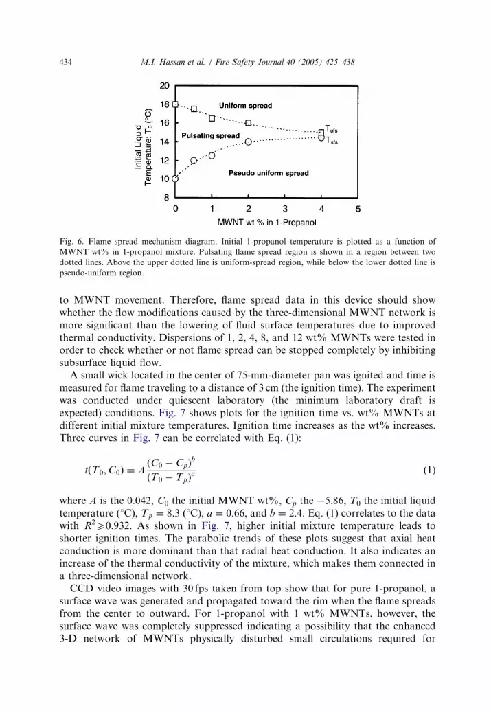
The fuel mixture with the highest MWNT content clearly has a slower flamespread rate. Fig. 6 shows a flame spread mechanism diagram for MWNT/1-propanolmixture as a function of initial temperature of the dispersion. Without conductivenanosolids in the fuel, the uniform flame spread/pulsating flame spread mechanismtransition occurs at 18 1C, while the pulsating flame spread/pseudo-uniform flamespread mechanism transition occurs at 10 1C. As the weight fraction of MWNTsincreases, the temperature range over which the pulsating flame spread mechanismoccurs is compressed. At 4 wt% MWNTs, the pulsating flame spread mechanismregion is difficult to detect. Above this MWNT loading, the flame spread rateappears to be uniform.
4.2. Physical and thermal effects of MWNTs
The possibility that MWNTs disrupt sub-surface liquid convection was furtherinvestigated using the apparatus in Fig. 2c. The 75-mm-diameter shallow pan cancreate surface waves as well as sub-surface liquid flow without side wall interference
ARTICLE IN PRESS
Fig. 6. Flame spread mechanism diagram. Initial 1-propanol temperature is plotted as a function of
MWNT wt% in 1-propanol mixture. Pulsating flame spread region is shown in a region between two
dotted lines. Above the upper dotted line is uniform-spread region, while below the lower dotted line is
pseudo-uniform region.
M.I. Hassan et al. / Fire Safety Journal 40 (2005) 425–438434
to MWNT movement. Therefore, flame spread data in this device should showwhether the flow modifications caused by the three-dimensional MWNT network ismore significant than the lowering of fluid surface temperatures due to improvedthermal conductivity. Dispersions of 1, 2, 4, 8, and 12 wt% MWNTs were tested inorder to check whether or not flame spread can be stopped completely by inhibitingsubsurface liquid flow.
A small wick located in the center of 75-mm-diameter pan was ignited and time ismeasured for flame traveling to a distance of 3 cm (the ignition time). The experimentwas conducted under quiescent laboratory (the minimum laboratory draft isexpected) conditions. Fig. 7 shows plots for the ignition time vs. wt% MWNTs atdifferent initial mixture temperatures. Ignition time increases as the wt% increases.Three curves in Fig. 7 can be correlated with Eq. (1):
tðT0;C0Þ ¼ AðC0 � CpÞ
b
ðT0 � TpÞa (1)
where A is the 0.042, C0 the initial MWNT wt%, Cp the �5.86, T0 the initial liquidtemperature (1C), Tp ¼ 8:3 (1C), a ¼ 0:66, and b ¼ 2:4. Eq. (1) correlates to the datawith R2
X0.932. As shown in Fig. 7, higher initial mixture temperature leads toshorter ignition times. The parabolic trends of these plots suggest that axial heatconduction is more dominant than that radial heat conduction. It also indicates anincrease of the thermal conductivity of the mixture, which makes them connected ina three-dimensional network.
CCD video images with 30 fps taken from top show that for pure 1-propanol, asurface wave was generated and propagated toward the rim when the flame spreadsfrom the center to outward. For 1-propanol with 1 wt% MWNTs, however, thesurface wave was completely suppressed indicating a possibility that the enhanced3-D network of MWNTs physically disturbed small circulations required for

ARTICLE IN PRESS
Fig. 7. Ignition time plotted as a function of 1-propanol/MWNTs mixtures at three different initial
1-propanol temperatures.
M.I. Hassan et al. / Fire Safety Journal 40 (2005) 425–438 435
formation of surface waves. We expect a similar enhanced mechanical effect ofMWNTs on sub-surface liquid convection, while the effect of enhanced thermalconductivity may be less important in changing the nature of flame spread overliquids.
Williams [19] discusses a surface-tension-driven flame spread rate equation, shownin Eq. (2):
V ¼
h
LðTc � T0Þ
dsdT
mF
0B@
1CA, (2)
where V is the flame spread rate, h the depth of sub-surface liquid convection, L thehorizontal distance ahead of the flames over which an elevated surface temperatureexists, Tc the flash point, s the surface tension, mF bulk viscosity of liquid. Table 2compares the calculated spread rate with the corresponding measured values forpure 1-propanol, 1-propanol with 1 wt% of MWNTs and 1-propanol with 2 wt%of MWNTs, where h/LE0.5 from Ref. [20], ds=dT ¼ 7:8� 10�5 (N/mK) fromRef. [21].
Our fuel depth (1 cm) satisfies the deep pool condition [19] which suggests thepossibility of gravity’s role in the flame spread rate in uniform spread region, asdiscussed in our earlier holographic interferometry study [6]. However, ourtemperature range here is lower than the uniform region and a long stretchedsurface-tension-driven flow was evident in the hologram [6] which largely differsfrom the one observed in the uniform region where a large round gravity-drivencirculation in addition to a long stretched surface-tension-driven flow was observed.In addition, with an addition of 1 wt%MWNTs to the fuel, we observed that surfacewaves which were created during flame spread over pure fuel were completely

ARTICLE IN PRESS
Table 2
Comparison between calculated flame spread rate and is measured for the initial 1-propanol temperature,
18 1C with and without MWNTs
MWNT wt%: C0 0 1 2
Calculated spread rate: Vc (cm/s) 12.0 4.44 1.20
Measured spread rate: Vm (cm/s) 12.5 4.1 1.44
M.I. Hassan et al. / Fire Safety Journal 40 (2005) 425–438436
eliminated. Based on these facts, we applied Eq. (2) to estimate the effects ofMWNTs on flame spread rate at the initial temperature 18 1C. The estimate was notmade for temperature 14 1C where a vigorous flame pulsation takes place whereEq. (2) loses its accuracy.
To estimate mF in 1-propanol with MWNT mixtures, we applied mF ¼ m0f ðfÞobtained for a rheological measurements of MWNTs dispersed in a synthetic motoroil [22], where mF is the viscosity of the suspension, m0 is the viscosity of thecontinuous phase at the temperature and pressure of interest, and f ðfÞ is a functionrelating the volume fraction of the solid and the shear rate of the flow to the viscosityof the dispersion. Velocity of our sub-surface liquid convection is approximately inthe range of 1 to 20 cm/s, so data taken for bulk fluid viscosities of different MWNTloadings at a constant shear rate of 0.1 s�1 can be approximately applied to estimatethe function, f ðfÞ. This shear rate represents the condition at which MWNT/oildispersions start to exhibit shear thinning due to nanotube alignment. As theMWNTs used in this study have a high aspect ratio with average lengths 410 m,nanotubes alignment can be observed by the unaided eye in other systems. However,no alignment of nanotubes was observed in the flame spread tests, and the shear rateof 0.1 s�1 was considered a reasonable representation of the conditions at which tocompare bulk viscosities of the MWNT dispersions. The value of the function isf ðfÞ � 1 for 1-propanol without MWNTs, f ðfÞ � 2:7 for 1 wt% MWCTs andf ðfÞ � 10 for 2 wt% MWCTs. Agreement in Table 2 and Fig. 8 between themeasured flame spread velocities and those calculated by Eq. (2) is very goodconsidering experimental uncertainty, and assumptions employed for estimating mF
and h/LE0.5 for 1-propanol with MWNTs.
4.3. Thermal conductivity of CNT networks
The thermal conductivity of carbon nanotubes and graphite is much higher alongx-plane of the graphitic sheet compared to the y-plane (or direction perpendicular tothe p-bonding electrons). For graphite, the values are 100W/m-K along the x-planedirection and 5.5W/m-K along the y-plane direction [23]. For single walled carbonnanotube bundles, the values are 950W/m-K along the x-plane direction and 5.6W/m-K along the y-plane direction [24]. The thermal conductivity of MWNTs alongtheir length axis is 950W/m-K [24], quite similar to that of graphite and single walledbundles. Assuming that the y-plane thermal conductivity of MWNTs isE5.6W/m-K,the geometric average provides a rough estimate of the bulk (nanotube phase only)

ARTICLE IN PRESS
Fig. 8. Comparison of the calculated flame spread rates using Eq. (2) with the corresponding measured
value for pure 1-propanol, 1 wt% MWNTs in 1-propanol, and 2 wt% MWNTs in 1-propanol.
M.I. Hassan et al. / Fire Safety Journal 40 (2005) 425–438 437
thermal conductivity, which would be E73W/m-K. This is still much higher thanthat of 1-propanol (0.16W/m-K [25]). As the MWNT wt% increases, there will be ahigher volume fraction of nanotubes as well as a greater number of contacts betweennanotubes. Both factors should increase the effective thermal conductivity of thethree-dimensional network. The nanotube network would also restrict bulk fluidflow, acting as a porous solid. The Ergun equation for pressure drop of fluidsthrough fibrous networks is linked to the Reynolds number (based on the fiberdiameter, and the void volume for flow rate).
5. Conclusions
Mixing MWNTs in the liquid 1-propanol was found to significantly reduce flamespread rates over the fuel dispersion. Increasing the MWNT concentration in thedispersion changed the initial temperature conditions necessary for specific flamespread mechanisms to occur. Three-dimensional MWNT dispersion networks couldlower flame spread rates either by conducting energy away from the flame front or bydisrupting the liquid convective flows that accelerate the flame front process. Thelack of surface waves in a point source ignition test suggests that the liquidconvective flows have been significantly suppressed, and flame spread rates seemconsistent with a 1-D flame spread Eq. (2) for the circulation flow phenomenon that
ARTICLE IN PRESS
M.I. Hassan et al. / Fire Safety Journal 40 (2005) 425–438438
is based on properties of the liquid phase. However, more work is needed toquantitatively estimate the contributions of each mechanism (thermal conduction viathe nanotubes network and liquid flow suppression caused by the 3-D network) onflame spread rates in well dispersed MWNT/fuel mixtures.
Acknowledgements
The authors thank Rodney Andrews and David Jacques of the Center for AppliedEnergy Research for supplying the MWNTs used in this study. This study issupported in part by NASA under the contract NAG3-2567 and in part by NSFunder MRSEC program (Grant No. DMR-9809686).
References
[1] Akita K. Proc Combust Inst 1973;14:1075–83.
[2] Hirano T, Suzuki T, Mashiko I, Tanabe N. Combust Sci Tech 1980;22:83.
[3] Matsumoto Y, Saito T. Bull JSME 1981;24:160–7.
[4] Garcia-Ybarra PL, Antoranz JC, Sankovitch V, Castillo JL. Phys Rev E 1994;49:5225–9.
[5] Miller FJ, Ross HD. Proc Combust Inst 1998;27:2715–22.
[6] Ito A, Masuda D, Saito K. Combust Flame 1991;83:375–89.
[7] Glassman I, Dryer FL. Fire Safety J 1980;3:123–38.
[8] Ross HD. Prog Energy Combust Sci 1994;20:17–63.
[9] Sirignano W, Schiller D. In: Sawyer R, Dryer F, editors. Physical and chemical aspects of
combustion. New Jersey: Gordon and Breach; 1996.
[10] Iijima S. Nature 1991;354:56–7.
[11] Vander Wal RL, Hall LJ, Berger GM. Proc Combust Inst 2002;29:1079–85.
[12] Yuan L, Saito K, Pan CP, Williams FA, Gordon AS. Chem Phys Lett 2001;340:237–41.
[13] Eitan A, Jiang K, Dukes D, Andrews R, Schadler LS. Chem Mater 2003;15:3198–201.
[14] Andrews R, Jacques D, Rao AM, Derbyshire F, Qian D, Fan X, Dickey EC, Chen J. Chem Phys Lett
1999;303:467–74.
[15] Kashiwagi T, Grulke E, Hilding J, Groth K, Harris R, Butler K, Shields J, Kharchenko S, Douglas
J. Polymer 2004;45:4227–39.
[16] Ito A, Narumi A, Konishi T, Tashtoush G, Saito K, Cremers CJ. J Heat Transfer 1999;121:413–9.
[17] Konishi T, Ito A, Kudo Y, Saito K. Proc Combust Inst 2002;29:1087–92.
[18] Ross HD, Sotos RG. Proc Combust Inst 1990;23:1649–55.
[19] Williams FA. Combustion theory. Menlo Park, CA: The Benjamin/Cummings [chapter 12]; 1985.
[20] Takahashi K, Ito A, Kudo Y, Konishi T, Saito K. Proc Combust Inst 2005;30:2271–7.
[21] Design Institute of Physical Properties, AICHE.
[22] Yang Y, Grulke EA, Zhang ZG, Wu G. Rheological properties of carbon nanotubes and graphite
dispersions. Nano Sciene and Nano Technology 2005;5:571–9.
[23] Che J, Cagin T, Goddard III WA. Nanotechnology 2000;11:65–9.
[24] Kim P, Shi L, Majumdar A, McEuen PL. Phys Rev Lett 2001;87:215502/1–2155024.
[25] Sun J, Longtin JP, Irvine Jr. TF. Int J Heat Mass Transfer 2001;44:645–57.