distributed transmit beamforming: challenges and recent progress
TRANSCRIPT
Distributed Transmit Beamforming:
Challenges and Recent Progress
R. Mudumbai, D.R. Brown III, U. Madhow, and H.V. Poor
Abstract
Distributed transmit beamforming is a form of cooperative communication in which two or more infor-
mation sources simultaneously transmit a common message and control the phase of their transmissions so
that the signals constructively combine at an intended destination. Depending on the design objectives and
constraints, the power gains of distributed beamforming can be translated into dramatic increases in range,
rate, or energy efficiency. Distributed beamforming may also provide benefits in terms of security and inter-
ference reduction since less transmit power is scattered in unintended directions. Key challenges in realizing
these benefits, however, include coordinating the sources for information sharing and timing synchronization
and, most crucially, distributed carrier synchronization so that the transmissions combine constructively
at the destination. This article reviews promising recent results in architectures, algorithms, and working
prototypes which indicate that these challenges can be surmounted. Directions for future research needed
to translate the potential of distributed beamforming to practice are also discussed.
1 Introduction
In wireless communication systems, transmit beamforming refers to a technique in which an information sourcetransmits a radio-frequency signal over two or more antennas and aligns the phases of the transmissions acrossthe antennas such that, after propagation, the signals combine constructively at the destination. Fixing thepower radiated by a given antenna element, ideal transmit beamforming with N antennas results in an N2-fold gain in received power. Compared to single antenna transmission, transmit beamforming can thereforeyield increased range (an N -fold increase for free space propagation), increased rate (an N2-fold increase in apower-limited regime), or increased power efficiency (an N -fold decrease in the net transmitted power for a fixeddesired received power). In addition, since more power is directed in the desired direction, less is scattered inundesired directions, resulting in reduced interference and increased security.
Given the many advantages of transmit beamforming, it is natural to ask whether it can be emulated indistributed fashion using a network of cooperating single-antenna sources. In order to operate as a “distributedtransmit beamformer”, the sources must agree on a common message, transmit it at the “same time”, syn-chronize their carrier frequencies, and control their carrier phases so their signals combine constructively at thedestination. Hence, practical realization of this concept requires the development of implementable distributedtechniques for information sharing, timing synchronization, and carrier synchronization. While these constitutea daunting set of challenges, recent results from several different research groups provide promising approachesfor addressing them. The goal of this article is to take stock of the current state of the art, and to suggestdirections for future research in the design and implementation of wireless networks that exploit distributedbeamforming.
In addition to the N2-fold power gain from distributed beamforming, there is also a potential advantage interms of wireless propagation. Consider the Friis formula for free-space propagation,
PR = PT GT GR
λ2
16π2R2(1)
where PT and PR are the transmit and receive powers, respectively, GT and GR are the directivity gains ofthe transmit and receive antennas, respectively, R is the range between the antennas, and λ is the carrier
This research was supported in part by the U.S. National Science Foundation under grants CCF-04-47743, ANI-03-38807 and
CNS-06-25637.
1
wavelength. For fixed antenna gains, the propagation loss PT
PR
is smaller at longer wavelengths. However,
antenna gains take the form G = 4πAλ2 , where A is the effective area. Thus, in order to maintain a given
directivity as wavelength increases, one must also scale the effective area of each antenna by λ2, which can makelonger wavelengths unattractive. With distributed transmit beamforming, it is possible to have the best of bothworlds: low propagation loss by operating at a long wavelength and high directivity by exploiting the naturalspatial distribution of the cooperating nodes to emulate a large antenna array. While this argument is presentedfor free space propagation, longer wavelengths provide even more of an advantage in cluttered environments,since the radio waves are better able to diffract around obstacles.
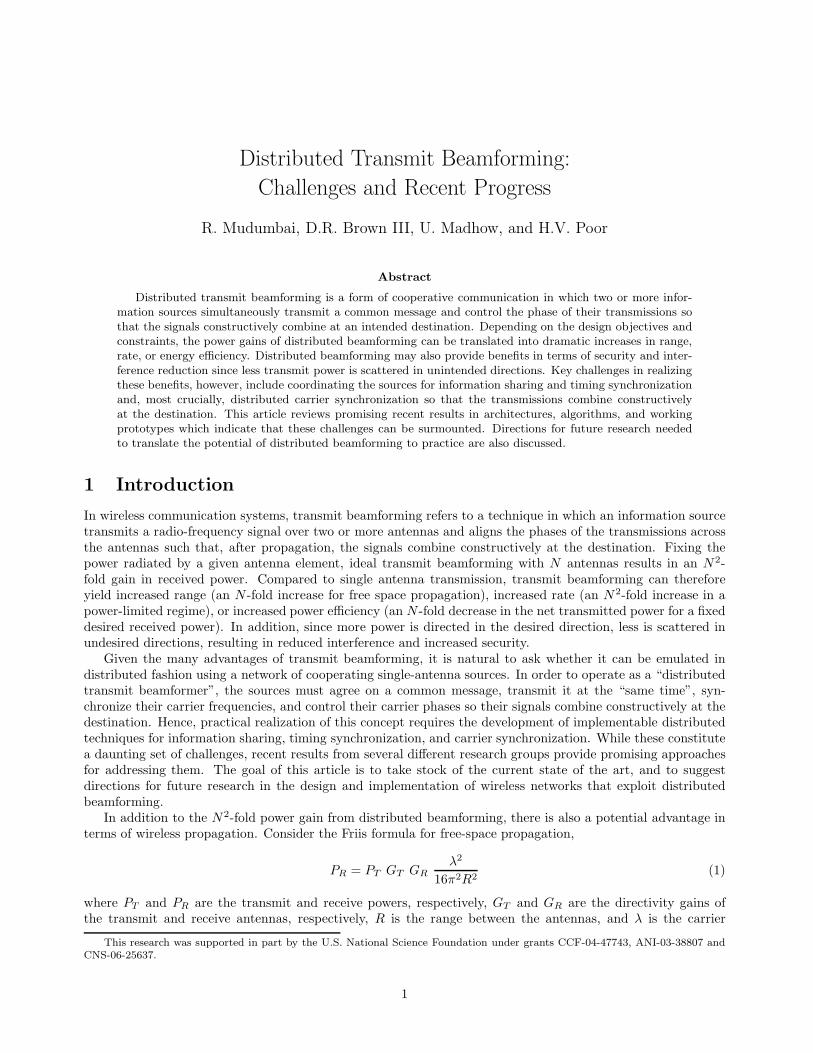
Figure 1: Sensor network transmitting measurements to an overflying aircraft.
As an example application, consider the scenario shown in Figure 1, where a terrestrially deployed network oflow-power single-antenna sensor nodes collects measurements and transmits these measurements to an overflyingunmanned aerial vehicle (UAV) using a carrier frequency of 3 GHz and a bandwidth of 10 MHz. For a sensortransmit power of -10 dBm, the received power at an altitude of 3000 meters (typical for intermediate rangeUAVs) is -110 dBm, assuming a sensor transmit antenna gain of GT = 2 dBi and receive antenna gain GR =10 dBi for the aircraft. For a receiver noise figure of 6 dB, the noise power is -97 dBm (thermal noise at300 Kelvin has a power spectral density of -173dBm/Hz). Thus, the signal-to-noise ratio (SNR) for a single sensortransmission is -13 dB, making communication with reasonable spectral efficiency infeasible. On the other hand,the SNR increases to +13 dB if 20 sensor nodes form a distributed transmit beamformer. This could enable,for example, upload of image/video data, or of summaries of sensor data gathered over days or even months.Other interesting applications include reachback using low-power soldier radios in battlefield communication,and collaboration between subscriber terminals for uplink transmission to a base station receiver, especially inrural or disaster recovery settings where longer range might be required.
As the preceding examples indicate, distributed transmit beamforming has the potential of enabling funda-mentally new functionalities in wireless communication and sensor networks. In the remainder of this article,we discuss some of the technical issues that must be addressed in order to realize this potential. We reviewrecent progress on the crucial distributed carrier synchronization problem in Section 2 and describe two workingprototypes in Section 5 which suggest that this problem is solvable. In Section 3, we discuss the characteristicsof beampatterns realizable using distributed transmit beamforming with randomly placed sources. These resultslay the foundation for “physical layer” feasibility of distributed transmit beamforming. In Section 4, we thendiscuss the cross-layer design considerations for information sharing and coordination among sources. We end
2
in Section 6 with a discussion of directions for future research.
2 Distributed Carrier Synchronization
A key distinguishing feature of distributed transmit beamforming with respect to conventional beamformingis that each source node in a distributed beamformer has an independent local oscillator (LO). These LOsare typically generated by multiplying the frequency of a crystal oscillator up to a fixed nominal frequency.Carrier frequencies generated in this manner, however, typically exhibit variations of the order of 10-100 partsper million (ppm) with respect to the nominal. If uncorrected, these frequency variations among the sourcesare catastrophic for transmit beamforming since the phases of the signals may drift out of alignment over theduration of the transmission and may even result in destructive combining at the destination. The first goal,therefore, is to synchronize the carrier frequencies for the different sources to minimize or eliminate frequencyoffset.
One approach to frequency synchronization is to employ a master-slave architecture [1, 2], where “slave”source nodes use phase-locked loops (PLLs) to lock to a reference carrier signal broadcast by a “master”source node. Alternatively, the destination node could broadcast a reference carrier to facilitate frequencysynchronization among the source nodes [3, 4, 5]. A source node which estimates its frequency offset to be ∆fcan multiply its complex baseband transmitted signal by e−j2π∆ft, where the operation can be implementedin digital signal processor (DSP) prior to digital-to-analog conversion and carrier multiplication. Depending onthe stability of the sources’ oscillators, the process of frequency synchronization may need to be repeated, andshould be inherent to any networking protocol built around distributed beamforming.
Once frequency synchronization is achieved, the phase of the transmissions from the different sources mustbe synchronized to arrive with “reasonable” alignment at the destination. To understand why carrier phasesynchronization is critical for distributed beamforming, consider first transmit beamforming using an N -elementcentralized array. To send a complex baseband message signal s(t), the signal transmitted from antenna i iswis(t), and the received signal is
∑
i wihis(t), where hi is the complex channel gain from antenna i to the receiver.The received SNR is therefore proportional to |
∑
iwihi|2. Given a constraint on the total transmitted power
∑
i |wi|2, it can be shown that the SNR is maximized by choosing wi ∝ h∗
i , i.e. |wi| ∝ |hi| and 6 wi = − 6 hi.Another option, appropriate for a peak power constraint per antenna element, is to use a fixed amplitude|wi| = wmax and 6 wi = − 6 hi. When the channel gains are approximately equal in magnitude, both methods
have similar performance: the received signal |∑N
i=1wihi| ∝ N , so that the received SNR scales as N2. In
either case, the transmitter requires channel state information (CSI) regarding the {hi}, with the phase 6 hibeing the critical information required for obtaining beamforming gains. Techniques for obtaining CSI at thetransmitter fall into two broad categories: implicit feedback (e.g., using reciprocity in a time division duplexed(TDD) system), and explicit feedback, where the CSI is quantized and sent over a separate feedback channel.A detailed review of different beamforming techniques is given in [6].
In distributed beamforming scenarios, the sources are assumed to be unsynchronized a priori. This lackof synchronization leads to ambiguous phase estimates at each source. To see this, consider first implicitchannel feedback using reciprocity. Ignoring modulation and noise for simplicity, source node i receives thepassband signal Re
(
hiej2πfct
)
. When this is downconverted using the local oscillator (LO) at node i, usingthe quadrature carriers cos(2πfct + θi) and sin(2πfct + θi), the complex baseband channel estimate at node i
will be hi = hie−jθi . Without carrier synchronization across nodes, the local oscillator phases {θi} may be
modeled as independent and uniformly distributed over (−π, π], which implies that the phase of the channelestimate contains no information about the actual channel phase. In other words, the channel phase can notbe disambiguated from the relative LO phase at node i with this approach. Now, suppose instead that thereceiver measures the channel gains from each node, and feeds them back explicitly. When node i employs theseexplicit channel estimates, however, it must upconvert the baseband message using its LO, which means thatit is effectively using the beamforming weight wi = h∗
i ejθi . Again, the phase of the beamforming coefficient is
essentially random without prior carrier synchronization across the nodes.The preceding observations show that, even under ideal timing synchronization across nodes, distributed
beamforming is impossible without distributed carrier synchronization. Nonidealities in timing synchroniza-tion can also affect distributed beamforming, but the effects are easier to handle. Timing synchronization isrequired to ensure that all of the cooperating nodes transmit the same symbol at a given time; timing errors
3
between the nodes lead to misalignment between the symbols transmitted by each node, causing inter-symbolinterference (ISI) at the receiver. For relatively low data rates (say around 100 Kbps), the required level oftiming synchronization can be obtained using well-known algorithms such as RBS [7]. These algorithms arecapable of achieving accuracy on the order of 1µs with low complexity. For higher data rates, customizedtiming synchronization techniques might be needed to achieve the desired level of accuracy. Even with accuratetiming synchronization, however, ISI can arise due to dispersive channels from each node to the receiver. Anatural approach for handling this is multicarrier modulation: in this case, distributed beamforming would beperformed separately for each subcarrier. For single-carrier modulation, we may wish to use transmit precodingto ensure that the same symbol sent by different transmitters appears at approximately the same time at thereceiver. Thus, while timing synchronization does pose a challenge, it is not as fundamental a bottleneck ascarrier synchronization, hence we focus on the latter in this paper.
There are two basic approaches to phase synchronization distinguished by the interaction between the sourcesand the destination:
1. Closed-loop phase synchronization: In closed-loop systems, the destination directly controls the phasealignment among the sources by measuring a function of the received phases of the source transmissionsand then transmitting digital feedback signals to the sources to allow each source to compensate for itsoverall phase offset (LO and channel). Interaction among the sources can be minimal in closed-loopsystems since the destination coordinates the synchronization process.
2. Open-loop phase synchronization: In open-loop systems, the sources interact among themselves withonly minimal signaling from the destination. Rather than providing feedback to be used for adapting thesource phases, the destination may simply broadcast an unmodulated sinusoidal beacon to the sources. Thesources use this beacon, as well as the signals from other source-source interactions, to achieve appropriatephase compensation for beamforming to the destination. The emphasis of open-loop systems is in usinglocal interactions between the sources to minimize interaction with the distant destination.
Regardless of the synchronization approach, it is known that beamforming gains are quite robust to moderateerrors in phase alignment. For example, 90% of an ideal two-antenna beamforming power gain is attained evenwith phase offsets of the order of 30◦ [1, 2].
2.1 Full-Feedback Closed-Loop Synchronization
The first carrier synchronization scheme suitable for distributed beamforming is described in [3]. Carrier fre-quency synchronization is achieved using a master-slave approach, with the intended destination acting as themaster node. The unknown phase offset between the destination and the nth source node is corrected via aclosed-loop protocol realized in the following steps:
1. The destination broadcasts a common master beacon to all source nodes.
2. Each source node “bounces” the master beacon back to the destination on a different frequency than themaster beacon. The source nodes use distinct codes in a direct-sequence code division multiple access(DS-CDMA) scheme in order to allow the destination to distinguish the received signals.
3. Upon reception the bounced beacons, the destination estimates the received phase of each source relativeto the originally transmitted master beacon. The destination divides these estimates by two, quantizesthem, and then transmits the estimates via DS-CDMA to the source nodes in a “phase compensationmessage”. The phase compensation message may also contain clock correction information to facilitatesymbol timing synchronization.
4. Each source receives the phase compensation message, extracts its own phase compensation estimate, andthen adjusts its carrier phase accordingly.
Assuming that the phase offsets have not changed significantly between the synchronization and beamformingintervals, the bandpass transmissions from each source will combine coherently when the sources transmit tothe destination with compensated carrier phases. The effect of energy allocation between synchronization andinformation transmission on the error probability of digital signals transmitted by a distributed beamformerwas also studied in [3]. The results showed that an optimal energy tradeoff exists and that allocating too muchor too little energy to carrier synchronization is inefficient.
4
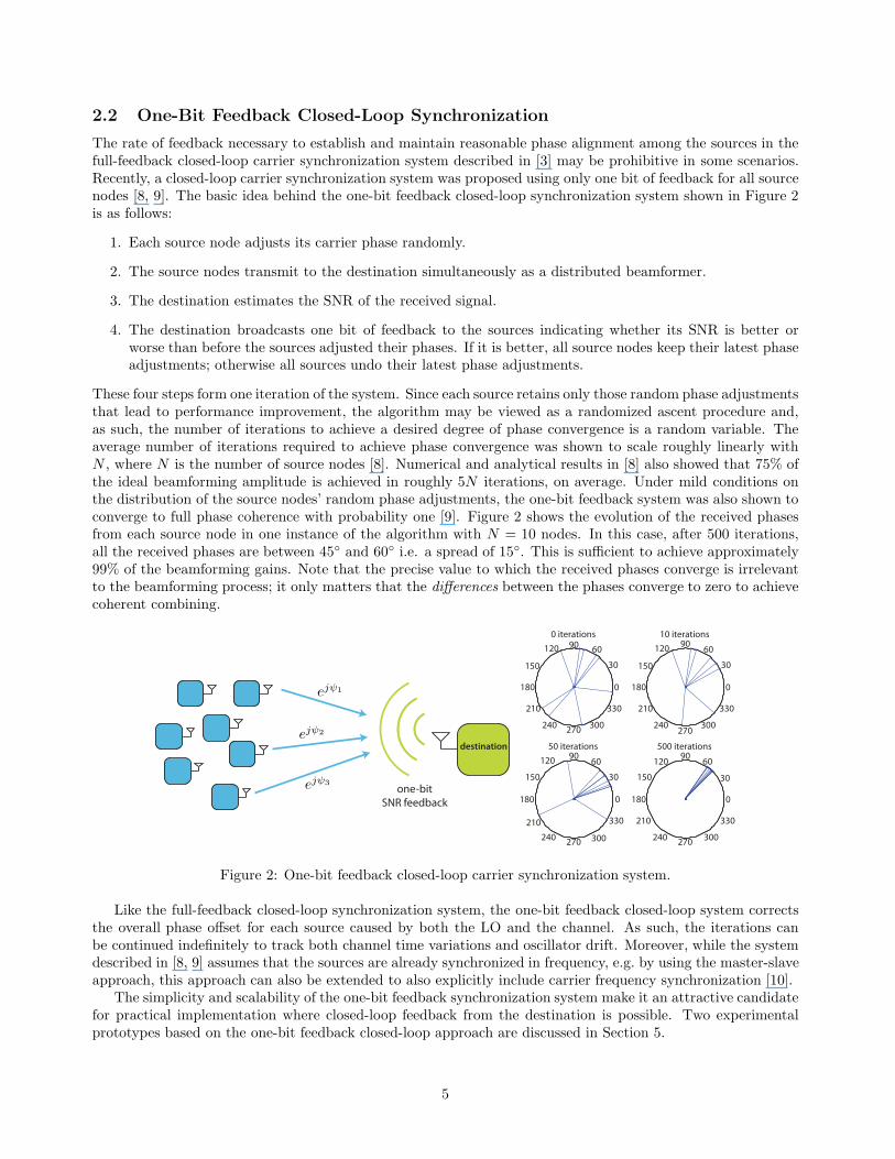
2.2 One-Bit Feedback Closed-Loop Synchronization
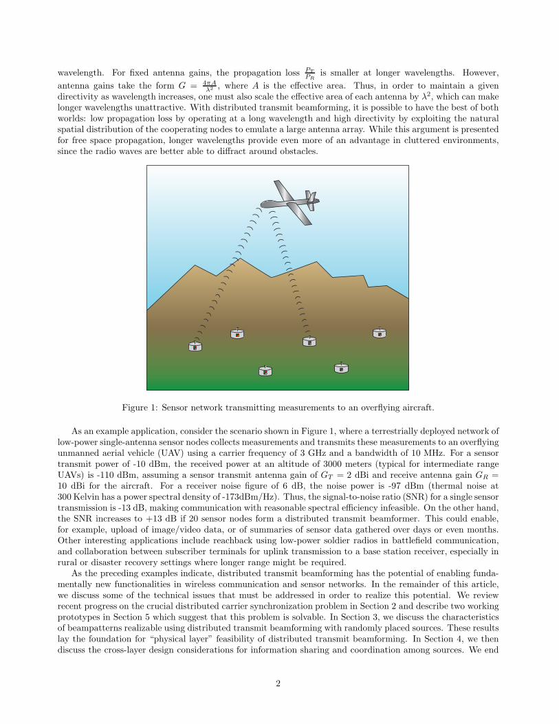
The rate of feedback necessary to establish and maintain reasonable phase alignment among the sources in thefull-feedback closed-loop carrier synchronization system described in [3] may be prohibitive in some scenarios.Recently, a closed-loop carrier synchronization system was proposed using only one bit of feedback for all sourcenodes [8, 9]. The basic idea behind the one-bit feedback closed-loop synchronization system shown in Figure 2is as follows:
1. Each source node adjusts its carrier phase randomly.
2. The source nodes transmit to the destination simultaneously as a distributed beamformer.
3. The destination estimates the SNR of the received signal.
4. The destination broadcasts one bit of feedback to the sources indicating whether its SNR is better orworse than before the sources adjusted their phases. If it is better, all source nodes keep their latest phaseadjustments; otherwise all sources undo their latest phase adjustments.
These four steps form one iteration of the system. Since each source retains only those random phase adjustmentsthat lead to performance improvement, the algorithm may be viewed as a randomized ascent procedure and,as such, the number of iterations to achieve a desired degree of phase convergence is a random variable. Theaverage number of iterations required to achieve phase convergence was shown to scale roughly linearly withN , where N is the number of source nodes [8]. Numerical and analytical results in [8] also showed that 75% ofthe ideal beamforming amplitude is achieved in roughly 5N iterations, on average. Under mild conditions onthe distribution of the source nodes’ random phase adjustments, the one-bit feedback system was also shown toconverge to full phase coherence with probability one [9]. Figure 2 shows the evolution of the received phasesfrom each source node in one instance of the algorithm with N = 10 nodes. In this case, after 500 iterations,all the received phases are between 45◦ and 60◦ i.e. a spread of 15◦. This is sufficient to achieve approximately99% of the beamforming gains. Note that the precise value to which the received phases converge is irrelevantto the beamforming process; it only matters that the differences between the phases converge to zero to achievecoherent combining.
destination
one-bit
SNR feedback
30
210
60
240
90
270
120
300
150
330
180 0
0 iterations
30
210
60
240
90
270
120
300
150
330
180 0
10 iterations
30
210
60
240
90
270
120
300
150
330
180 0
50 iterations
30
210
60
240
90
270
120
300
150
330
180 0
500 iterations
ejψ1
ejψ2
ejψ3
Figure 2: One-bit feedback closed-loop carrier synchronization system.
Like the full-feedback closed-loop synchronization system, the one-bit feedback closed-loop system correctsthe overall phase offset for each source caused by both the LO and the channel. As such, the iterations canbe continued indefinitely to track both channel time variations and oscillator drift. Moreover, while the systemdescribed in [8, 9] assumes that the sources are already synchronized in frequency, e.g. by using the master-slaveapproach, this approach can also be extended to also explicitly include carrier frequency synchronization [10].
The simplicity and scalability of the one-bit feedback synchronization system make it an attractive candidatefor practical implementation where closed-loop feedback from the destination is possible. Two experimentalprototypes based on the one-bit feedback closed-loop approach are discussed in Section 5.
5
2.3 Master-Slave Open-Loop Synchronization
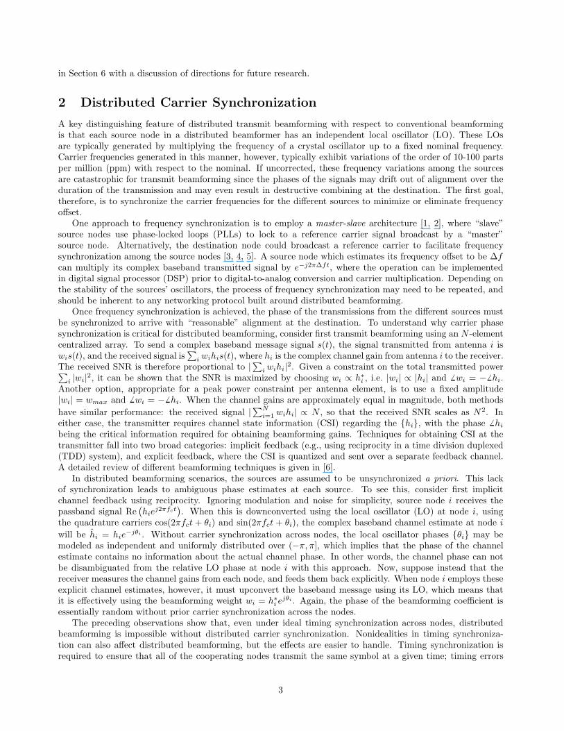
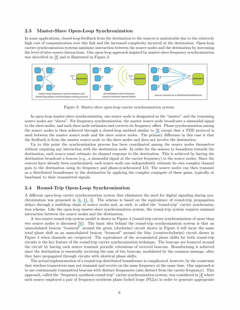
In some applications, closed-loop feedback from the destination to the sources is undesirable due to the relativelyhigh cost of communication over this link and the increased complexity incurred at the destination. Open-loopcarrier synchronization systems minimize interaction between the source nodes and the destination by increasingthe level of inter-source interactions. One open-loop approach inspired by master-slave frequency synchronizationwas described in [2] and is illustrated in Figure 3.
destination
master-slave frequency synchronization and
closed-loop phase synchronization among sources
unmodulated carrier broacast;
sources estimate channel phase
destination destination
sources transmit as a distributed beamformer
Figure 3: Master-slave open-loop carrier synchronization system.
In open-loop master-slave synchronization, one source node is designated as the “master” and the remainingsource nodes are “slaves”. For frequency synchronization, the master source node broadcasts a sinusoidal signalto the slave nodes, and each slave node estimates and corrects its frequency offset. Phase synchronization amongthe source nodes is then achieved through a closed-loop method similar to [3] except that a TDD protocol isused between the master source node and the slave source nodes. The primary difference in this case is thatthe feedback is from the master source node to the slave nodes and does not involve the destination.
Up to this point the synchronization process has been coordinated among the source nodes themselveswithout requiring any interaction with the destination node. In order for the sensors to beamform towards thedestination, each source must estimate its channel response to the destination. This is achieved by having thedestination broadcast a beacon (e.g., a sinusoidal signal at the carrier frequency) to the source nodes. Since thesources have already been synchronized, each source node can independently estimate its own complex channelgain to the destination using its frequency and phase-synchronized LO. The source nodes can then transmitas a distributed beamformer to the destination by applying the complex conjugate of these gains, typically atbaseband, to their transmitted signals.
2.4 Round-Trip Open-Loop Synchronization
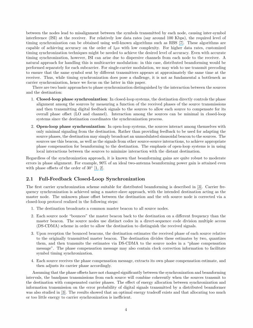
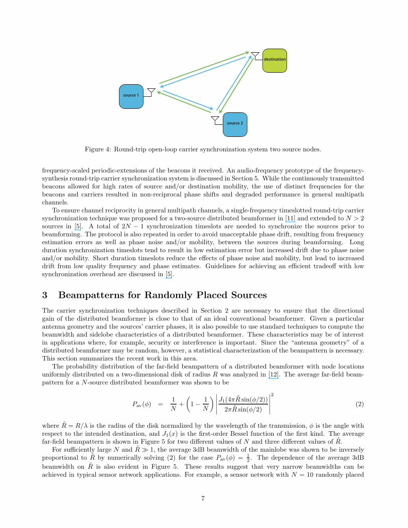
A different open-loop carrier synchronization system that eliminates the need for digital signaling during syn-chronization was proposed in [4, 11, 5]. The scheme is based on the equivalence of round-trip propagationdelays through a multihop chain of source nodes and, as such, is called the “round-trip” carrier synchroniza-tion scheme. Like the open-loop master-slave synchronization system, the round-trip system requires minimalinteraction between the source nodes and the destination.
A two-source round-trip system model is shown in Figure 4 (round-trip carrier synchronization of more thantwo source nodes is discussed [5]). The basic idea behind the round-trip synchronization system is that anunmodulated beacon “bounced” around the green (clockwise) circuit shown in Figure 4 will incur the sametotal phase shift as an unmodulated beacon “bounced” around the blue (counterclockwise) circuit shown inFigure 4 when channels are reciprocal. The equivalence of the accumulated phase shifts for both round-tripcircuits is the key feature of the round-trip carrier synchronization technique. The beacons are bounced aroundthe circuit by having each source transmit periodic extensions of received beacons. Beamforming is achievedsince the destination is essentially receiving the sum of two beacons, modulated by the common message, afterthey have propagated through circuits with identical phase shifts.
The actual implementation of a round-trip distributed beamformer is complicated, however, by the constraintthat wireless transceivers may not transmit and receive on the same frequency at the same time. One approach isto use continuously transmitted beacons with distinct frequencies (also distinct from the carrier frequency). Thisapproach, called the “frequency-synthesis round-trip” carrier synchronization system, was considered in [4] whereeach source employed a pair of frequency-synthesis phase locked loops (PLLs) in order to generate appropriate
6
destination
source 1
source 2
Figure 4: Round-trip open-loop carrier synchronization system two source nodes.
frequency-scaled periodic-extensions of the beacons it received. An audio-frequency prototype of the frequency-synthesis round-trip carrier synchronization system is discussed in Section 5. While the continuously transmittedbeacons allowed for high rates of source and/or destination mobility, the use of distinct frequencies for thebeacons and carriers resulted in non-reciprocal phase shifts and degraded performance in general multipathchannels.
To ensure channel reciprocity in general multipath channels, a single-frequency timeslotted round-trip carriersynchronization technique was proposed for a two-source distributed beamformer in [11] and extended to N > 2sources in [5]. A total of 2N − 1 synchronization timeslots are needed to synchronize the sources prior tobeamforming. The protocol is also repeated in order to avoid unacceptable phase drift, resulting from frequencyestimation errors as well as phase noise and/or mobility, between the sources during beamforming. Longduration synchronization timeslots tend to result in low estimation error but increased drift due to phase noiseand/or mobility. Short duration timeslots reduce the effects of phase noise and mobility, but lead to increaseddrift from low quality frequency and phase estimates. Guidelines for achieving an efficient tradeoff with lowsynchronization overhead are discussed in [5].
3 Beampatterns for Randomly Placed Sources
The carrier synchronization techniques described in Section 2 are necessary to ensure that the directionalgain of the distributed beamformer is close to that of an ideal conventional beamformer. Given a particularantenna geometry and the sources’ carrier phases, it is also possible to use standard techniques to compute thebeamwidth and sidelobe characteristics of a distributed beamformer. These characteristics may be of interestin applications where, for example, security or interference is important. Since the “antenna geometry” of adistributed beamformer may be random, however, a statistical characterization of the beampattern is necessary.This section summarizes the recent work in this area.
The probability distribution of the far-field beampattern of a distributed beamformer with node locationsuniformly distributed on a two-dimensional disk of radius R was analyzed in [12]. The average far-field beam-pattern for a N -source distributed beamformer was shown to be
Pav(φ) =1
N+
(
1 −1
N
)
∣
∣
∣
∣
∣
J1(4πR sin(φ/2))
2πR sin(φ/2)
∣
∣
∣
∣
∣
2
(2)
where R = R/λ is the radius of the disk normalized by the wavelength of the transmission, φ is the angle withrespect to the intended destination, and J1(x) is the first-order Bessel function of the first kind. The averagefar-field beampattern is shown in Figure 5 for two different values of N and three different values of R.
For sufficiently large N and R ≫ 1, the average 3dB beamwidth of the mainlobe was shown to be inverselyproportional to R by numerically solving (2) for the case Pav(φ) = 1
2. The dependence of the average 3dB
beamwidth on R is also evident in Figure 5. These results suggest that very narrow beamwidths can beachieved in typical sensor network applications. For example, a sensor network with N = 10 randomly placed
7
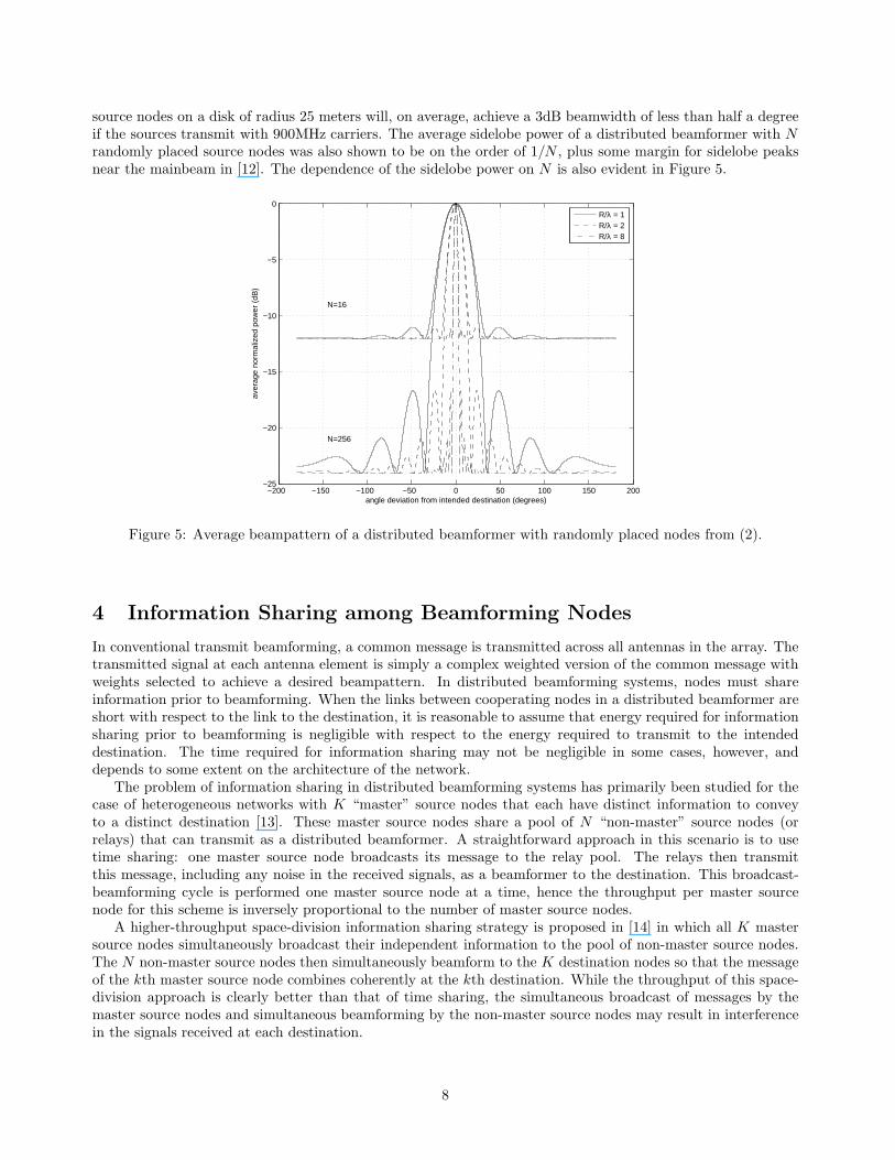
source nodes on a disk of radius 25 meters will, on average, achieve a 3dB beamwidth of less than half a degreeif the sources transmit with 900MHz carriers. The average sidelobe power of a distributed beamformer with Nrandomly placed source nodes was also shown to be on the order of 1/N , plus some margin for sidelobe peaksnear the mainbeam in [12]. The dependence of the sidelobe power on N is also evident in Figure 5.
−200 −150 −100 −50 0 50 100 150 200−25
−20
−15
−10
−5
0
angle deviation from intended destination (degrees)
aver
age
norm
aliz
ed p
ower
(dB
)
N=16
N=256
R/λ = 1R/λ = 2R/λ = 8
Figure 5: Average beampattern of a distributed beamformer with randomly placed nodes from (2).
4 Information Sharing among Beamforming Nodes
In conventional transmit beamforming, a common message is transmitted across all antennas in the array. Thetransmitted signal at each antenna element is simply a complex weighted version of the common message withweights selected to achieve a desired beampattern. In distributed beamforming systems, nodes must shareinformation prior to beamforming. When the links between cooperating nodes in a distributed beamformer areshort with respect to the link to the destination, it is reasonable to assume that energy required for informationsharing prior to beamforming is negligible with respect to the energy required to transmit to the intendeddestination. The time required for information sharing may not be negligible in some cases, however, anddepends to some extent on the architecture of the network.
The problem of information sharing in distributed beamforming systems has primarily been studied for thecase of heterogeneous networks with K “master” source nodes that each have distinct information to conveyto a distinct destination [13]. These master source nodes share a pool of N “non-master” source nodes (orrelays) that can transmit as a distributed beamformer. A straightforward approach in this scenario is to usetime sharing: one master source node broadcasts its message to the relay pool. The relays then transmitthis message, including any noise in the received signals, as a beamformer to the destination. This broadcast-beamforming cycle is performed one master source node at a time, hence the throughput per master sourcenode for this scheme is inversely proportional to the number of master source nodes.
A higher-throughput space-division information sharing strategy is proposed in [14] in which all K mastersource nodes simultaneously broadcast their independent information to the pool of non-master source nodes.The N non-master source nodes then simultaneously beamform to the K destination nodes so that the messageof the kth master source node combines coherently at the kth destination. While the throughput of this space-division approach is clearly better than that of time sharing, the simultaneous broadcast of messages by themaster source nodes and simultaneous beamforming by the non-master source nodes may result in interferencein the signals received at each destination.
8
5 Proof-of-Concept Prototypes
As theoretical research on distributed transmit beamforming has advanced, experimental prototypes have re-cently been constructed to confirm theoretical predictions and to better understand the inherent non-idealitiesin practical realizations. This section describes two such prototypes and summaries the results of the laboratoryexperiments.
5.1 One-Bit Feedback Closed-Loop Synchronization Prototype
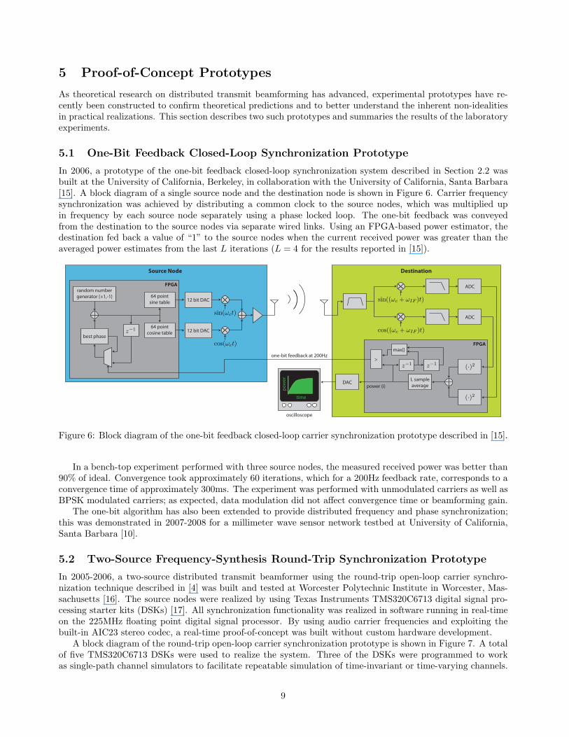
In 2006, a prototype of the one-bit feedback closed-loop synchronization system described in Section 2.2 wasbuilt at the University of California, Berkeley, in collaboration with the University of California, Santa Barbara[15]. A block diagram of a single source node and the destination node is shown in Figure 6. Carrier frequencysynchronization was achieved by distributing a common clock to the source nodes, which was multiplied upin frequency by each source node separately using a phase locked loop. The one-bit feedback was conveyedfrom the destination to the source nodes via separate wired links. Using an FPGA-based power estimator, thedestination fed back a value of “1” to the source nodes when the current received power was greater than theaveraged power estimates from the last L iterations (L = 4 for the results reported in [15]).
12 bit DAC
12 bit DAC
64 point
cosine table
64 point
sine table
best phase
random number
generator {+1,-1}
FPGA ADC
ADC
L sample
average
max{}
>
power (i)DAC
FPGA
one-bit feedback at 200Hz
time
po
we
r
oscilloscope
Source Node Destination
sin((ωc + ωIF )t)
cos((ωc + ωIF )t)
(·)2
(·)2
z−1 z−1
sin(ωct)
cos(ωct)
z−1
Figure 6: Block diagram of the one-bit feedback closed-loop carrier synchronization prototype described in [15].
In a bench-top experiment performed with three source nodes, the measured received power was better than90% of ideal. Convergence took approximately 60 iterations, which for a 200Hz feedback rate, corresponds to aconvergence time of approximately 300ms. The experiment was performed with unmodulated carriers as well asBPSK modulated carriers; as expected, data modulation did not affect convergence time or beamforming gain.
The one-bit algorithm has also been extended to provide distributed frequency and phase synchronization;this was demonstrated in 2007-2008 for a millimeter wave sensor network testbed at University of California,Santa Barbara [10].
5.2 Two-Source Frequency-Synthesis Round-Trip Synchronization Prototype
In 2005-2006, a two-source distributed transmit beamformer using the round-trip open-loop carrier synchro-nization technique described in [4] was built and tested at Worcester Polytechnic Institute in Worcester, Mas-sachusetts [16]. The source nodes were realized by using Texas Instruments TMS320C6713 digital signal pro-cessing starter kits (DSKs) [17]. All synchronization functionality was realized in software running in real-timeon the 225MHz floating point digital signal processor. By using audio carrier frequencies and exploiting thebuilt-in AIC23 stereo codec, a real-time proof-of-concept was built without custom hardware development.
A block diagram of the round-trip open-loop carrier synchronization prototype is shown in Figure 7. A totalof five TMS320C6713 DSKs were used to realize the system. Three of the DSKs were programmed to workas single-path channel simulators to facilitate repeatable simulation of time-invariant or time-varying channels.
9
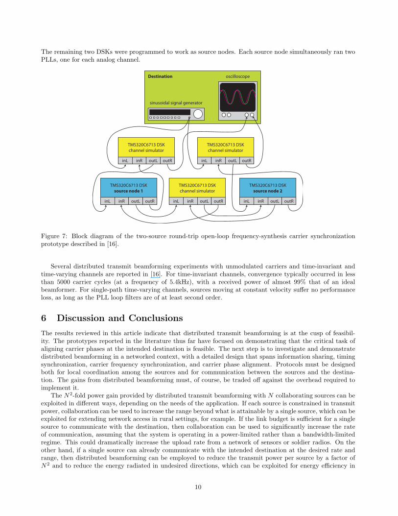
The remaining two DSKs were programmed to work as source nodes. Each source node simultaneously ran twoPLLs, one for each analog channel.
oscilloscope
sinusoidal signal generator
TMS320C6713 DSK
channel simulator
inL inR outL outR
TMS320C6713 DSK
channel simulator
inL inR outL outR
TMS320C6713 DSK
channel simulator
inL inR outL outR
TMS320C6713 DSK
source node 1
inL inR outL outR
TMS320C6713 DSK
source node 2
inL inR outL outR
Destination
Figure 7: Block diagram of the two-source round-trip open-loop frequency-synthesis carrier synchronizationprototype described in [16].
Several distributed transmit beamforming experiments with unmodulated carriers and time-invariant andtime-varying channels are reported in [16]. For time-invariant channels, convergence typically occurred in lessthan 5000 carrier cycles (at a frequency of 5.4kHz), with a received power of almost 99% that of an idealbeamformer. For single-path time-varying channels, sources moving at constant velocity suffer no performanceloss, as long as the PLL loop filters are of at least second order.
6 Discussion and Conclusions
The results reviewed in this article indicate that distributed transmit beamforming is at the cusp of feasibil-ity. The prototypes reported in the literature thus far have focused on demonstrating that the critical task ofaligning carrier phases at the intended destination is feasible. The next step is to investigate and demonstratedistributed beamforming in a networked context, with a detailed design that spans information sharing, timingsynchronization, carrier frequency synchronization, and carrier phase alignment. Protocols must be designedboth for local coordination among the sources and for communication between the sources and the destina-tion. The gains from distributed beamforming must, of course, be traded off against the overhead required toimplement it.
The N2-fold power gain provided by distributed transmit beamforming with N collaborating sources can beexploited in different ways, depending on the needs of the application. If each source is constrained in transmitpower, collaboration can be used to increase the range beyond what is attainable by a single source, which can beexploited for extending network access in rural settings, for example. If the link budget is sufficient for a singlesource to communicate with the destination, then collaboration can be used to significantly increase the rateof communication, assuming that the system is operating in a power-limited rather than a bandwidth-limitedregime. This could dramatically increase the upload rate from a network of sensors or soldier radios. On theother hand, if a single source can already communicate with the intended destination at the desired rate andrange, then distributed beamforming can be employed to reduce the transmit power per source by a factor ofN2 and to reduce the energy radiated in undesired directions, which can be exploited for energy efficiency in
10
sensor networks, or low-probability-of-intercept communication in military applications. While each applicationmay require a different cross-layer protocol and physical layer design, we hope that this article has conveyedthe fundamental issues that must be addressed by such a design.
References
[1] G. Barriac, R. Mudumbai, and U. Madhow, “Distributed beamforming for information transfer in sensornetworks,” in Proceedings of the Information Processing in Sensor Networks (IPSN), Third InternationalWorkshop, (Berkeley, CA), April 26-27, 2004.
[2] R. Mudumbai, G. Barriac, and U. Madhow, “On the feasibility of distributed beamforming in wirelessnetworks,” IEEE Trans. on Wireless Communications, vol. 6, pp. 1754–1763, May 2007.
[3] Y. Tu and G. Pottie, “Coherent cooperative transmission from multiple adjacent antennas to a distantstationary antenna through AWGN channels,” in Proceedings of the IEEE Vehicular Technology Conference(VTC), vol. 1, (Birmingham, AL), pp. 130–134, Spring 2002.
[4] D.R. Brown III, G. Prince, and J. McNeill, “A method for carrier frequency and phase synchronization oftwo autonomous cooperative transmitters,” in Proceedings of the 5th IEEE Signal Processing Advances inWireless Communications, (New York, NY), pp. 278–282, June 5-8, 2005.
[5] D. R. Brown III and H. V. Poor, “Time-slotted round-trip carrier synchronization for distributed beam-forming,” Signal Processing, IEEE Transactions on, vol. 56, pp. 5630–5643, Nov. 2008.
[6] L. C. Godara, “Application of antenna arrays to mobile communications. ii. beam-forming and direction-of-arrival considerations,” Proceedings of the IEEE, vol. 85, pp. 1195–1245, Aug 1997.
[7] J. Elson, L. Girod, and D. Estrin, “Fine-grained network time synchronization using reference broadcasts,”SIGOPS Oper. Syst. Rev., vol. 36, no. SI, pp. 147–163, 2002.
[8] R. Mudumbai, J. Hespanha, U. Madhow, and G. Barriac, “Scalable feedback control for distributed beam-forming in sensor networks,” in Proceedings of the IEEE International Symposium on Information Theory(ISIT2005), (Adelaide, Australia), pp. 137–141, September 2005.
[9] R. Mudumbai, J. Hespanha, U. Madhow, and G. Barriac, “Distributed transmit beamforming using feed-back control,” IEEE Trans. on Information Theory, in review.
[10] M. Seo, M. Rodwell, and U. Madhow, “A feedback-based distributed phased array technique and its ap-plication to 60-ghz wireless sensor network,” in IEEE MTT-S International Microwave Symposium Digest,(Atlanta, GA), pp. 683–686, June 15-20, 2008.
[11] I. Ozil and D.R. Brown III, “Time-slotted round-trip carrier synchronization,” in Proceedings of the 41stAsilomar Conference on Signals, Systems, and Computers, (Pacific Grove, CA), pp. 1781 – 1785, November4-7, 2007.
[12] H. Ochiai, P. Mitran, H.V. Poor, and V. Tarokh, “Collaborative beamforming for distributed wireless adhoc sensor networks,” IEEE Trans. on Signal Processing, vol. 53, pp. 4110 – 4124, November 2005.
[13] A. Dana and B. Hassibi, “On the power efficiency of sensory and ad hoc wireless networks,” IEEE Trans.on Information Theory, vol. 52, pp. 2890–2914, July 2006.
[14] L. Dong, P. Petropulu, and H.V. Poor, “A cross-layer approach to collaborative beamforming for wirelessad hoc networks,” IEEE Trans. on Signal Processing, vol. 56, pp. 2981–2993, July 2008.
[15] R. Mudumbai, B. Wild, U. Madhow, and K. Ramchandran, “Distributed beamforming using 1 bit feedback:from concept to realization,” in Proceedings of the of 44th Allerton Conference on Communication, Control,and Computing, (Monticello, IL), pp. 1020 – 1027, September 2006.
11
[16] James McGinley, “Real-time software-defined-radio implementation of a two-source distributed beam-former,” Master’s thesis, Worcester Polytechnic Institute, Worcester, MA, December 2006.
[17] R. Chassaing and D. Reay, Digital Signal Processing and Applications with the TMS320C6713 andTMS320C6416 DSK. Hoboken, NJ: John Wiley and Sons, second ed., 2008.
12