dipole localization for identification of neuronal generators in independent neighboring interictal...
TRANSCRIPT
Clinical Research
Dipole Localization for Identification of Neuronal Generators inIndependent Neighboring Interictal EEG Spike Foci
* ,†Ayako Ochi, *,†Hiroshi Otsubo, *,†Shiro Chitoku, †Amrita Hunjan, †Rohit Sharma,‡James T. Rutka, §Sylvester H. Chuang,\Ken-ichi Kamijo, \Toshimasa Yamazaki, and
* ,†O. Carter Snead III
*Bloorview Epilepsy Research Program, and †Division of Neurology, Department of Paediatrics, ‡Division of Neurosurgery,Department of Surgery, and §Department of Diagnostic Imaging, The Hospital for Sick Children and the University of Toronto,
Toronto, Ontario, Canada; and\Fundamental Research Laboratories, NEC Corporation, Tsukuba, Japan
Summary: Purpose: We evaluated dipole localizations of in-dependent neighboring interictal spike foci using scalp electro-encephalogram (EEG) to identify neuronal generators of epi-leptic discharges.
Methods:Three pediatric patients with extratemporal lobeepilepsy who had two independent neighboring interictal spikefoci on scalp EEG were studied. Prolonged video EEG wasdigitally recorded from 19 scalp electrodes, whose positionswere registered using a three-dimensional digitizer. Interictalspikes were visually selected based on negative phase reversalson bipolar montages. We analyzed the dipole position and mo-ment of each spike using a single moving dipole and three-shellspherical head model. The dipoles were overlaid onto magneticresonance (MR) images and divided into two groups based ontwo spike foci.
Results: The dipoles of the two groups were oriented eithertangentially or radially to the scalp in close proximity to each
other. The dipoles oriented radially were located underneath theelectrode with a negative peak; those oriented tangentially werebetween electrodes with a negative and positive peak. The po-sitions of tangential dipoles were more concentrated than thoseof radial dipoles. The epileptogenic regions corresponded to thedipole localizations. Surgical excisions were performed basedon the results of electrocorticography. After surgery, two pa-tients were seizure free, and one had rare seizures (follow-upperiod, 13–31 months).
Conclusions: We showed that dipoles in close proximity butwith different orientations projected two negative maxima onscalp EEG in three patients with extratemporal localization-related epilepsy. Equivalent current dipole analysis of indi-vidual interictal spikes can provide useful information aboutthe epileptogenic zone in these patients.Key Words: Tangen-tial dipole—Phase reversal—EEG—Dipole orientation—Children.
The main tasks in routine electroencephalography(EEG) are to recognize waveforms of diagnostic signifi-cance and identify the location of their generators withinthe brain (1). Studies (1–3) based on the solid angletheorem of volume conductor theory have shown that ahigher amplitude does not necessarily mean that the re-cording electrodes are closer to the neuronal source, be-cause the generators of the EEG are cortical pyramidalneurons, which have dipolar configurations.
Theoretically, in the EEG, when the polarity anywhereon the scalp is either negative or positive, such a field
would resemble that generated by a dipole layer locatedin the crown of the gyrus, often called a “radial” dipole.If the generator occupies a fissural cortex, the potentialdistribution on the scalp shows both positive and nega-tive polarities. Such a field is often referred to as a “tan-gential” dipole. Through variations in orientation andshape of the cerebral cortices, dipole layers can producecharge reorientation and cancellation (4). Equivalent cur-rent dipoles should be considered the best representationof the center of a dipole layer that corresponds to theactivity of a patch of cortex (5).
Previous studies of dipole localizations of interictalEEG spikes have considered the differences among di-pole orientations (6–9). Benign rolandic epilepsy ofchildhood without neurologic abnormalities (the typicalform) demonstrated a stable tangential dipole, whereas
Accepted December 11, 2000.Address correspondence and reprint requests to Dr. A. Ochi at Di-
vision of Neurology, The Hospital for Sick Children, 555 UniversityAvenue, Toronto, Ontario, M5G 1X8, Canada. E-mail: [email protected]
Epilepsia,42(4):483–490, 2001Blackwell Science, Inc.© International League Against Epilepsy
483

more than one dipole source was observed in patientswith the atypical form of the disorder, which includesneurologic or intellectual abnormalities (6–8). Van derMeij et al. (9) described the “double spike” phenomenon,consisting of a rolandic spike preceded by a small spikein its ascending phase. These two spike sources derivedfrom averaged spikes were located close together butshowed a different orientation.
In the current study, we hypothesized that a singleepileptic region could produce two independent neigh-boring spike foci on a scalp EEG. In three children withrefractory extratemporal lobe epilepsy, we describe therelationship between (a) positions and orientations oftwo dipole groups using individual spikes, and (b) theelectrode positions where the maximal voltage was re-corded.
METHODS
PatientsFive patients with extratemporal lobe epilepsy who
were studied for dipole localization underwent epilepsysurgery at The Hospital for Sick Children between 1996and 1999. Three of them had two independent neighbor-ing interictal spike foci noted on EEG, and were selectedfor study. Their parents gave informed consent for theirparticipation in the study.
Data acquisitionDigital prolonged video-EEGs were recorded from 19
scalp electrodes placed according to the International 10-20 system (BMSI 5000; Nicolet, Madison, WI, U.S.A.).A single reference was used at FCz in patient 1 and Ozin patients 2 and 3. The sampling rate was 200 Hz (a 1-to 70-Hz bandpass filter). Interictal spikes were visuallyselected and categorized according to the electrode ofnegative phase reversal on either longitudinal or trans-verse bipolar montages.
The scalp electrode positions were registered using3SPACE ISOTRAK II (Polhemus, Colchester, VT,U.S.A.) combined with equivalent current dipole local-ization software for Windows, SynaPointPro (GE Mar-quette Medical System Japan, Ltd., Tokyo, Japan). Afterthe electrode positioning had been registered, measuredelectrode locations were fitted to the sphere (10). In ad-dition, three fiduciary points (nasion, and right and leftpreauricular points) were obtained for EEG and magneticresonance imaging (MRI) coregistration. Figure 1 showsthe coordinate system used in SynaPointPro.
Data analysisEEG spike samples were filtered with a high pass of 5
Hz and a low pass of 35 Hz, with a notch filter (60 Hz)for equivalent current dipole analysis. We analyzed thedipole localization of EEG spikes using a single movingdipole inverse-solution algorithm, a three-shell spherical
head model, and electrode-positioning data (SynaPoint-Pro). We have previously reported our algorithm andmethods of equivalent current dipole analysis (10,11). Inthe current study, goodness of fit (GoF) was appliedinstead of residual variance [GoF4 100 – residual vari-ance (%)]. The algorithm of this program calculates theinverse solution from 10 random, computer-generatedinitial guesses within the head model and chooses thehighest GoF at each time point because the inverse prob-lem has no unique solution.
Duration of 100 ms before and after the maximalnegative peak was examined in each spike. The dipolefits occurred every 5 ms. We chose the dipoles thatshowed a GoF >95%and that existed from the spike’sonset to its maximal negative peak. We calculated theangle between the mean dipole orientations of two inde-pendent spike groups, using the cosine of each normal-ized moment.
NeuroimagingThe dipole localizations were overlaid onto the MR
images of each patient’s brain. MRI (GE Signa 1.5 Tesla;General Electric Medical Systems, Milwaukee, WI,U.S.A.) yielded continuous 124 T1-weighted coronalslices with a thickness of 2 mm, a pixel size of 0.781mm, and a 256 × 256 image matrix. The SynaPointProprogram was used for superimposition of the dipoles onthe MR images (coronal, axial, and sagittal views).
RESULTS
Table 1 shows the clinical profiles of the three patientsstudied. The total number of spikes and time points ana-lyzed for dipole localizations and selected by our criteria,according to the electrode with a negative phase reversal,
FIG. 1. Coordinate system for EEG dipole position and momentin the SynaPointPro program. The center of the head is definedas the point where the y-axis (nasion–inion line) perpendicularlyintersects the x-axis (auricular line, with positive value right ofcenter and negative value left of center). The z-axis extends fromthe center toward the vertex of the head at a right angle. Valuesfor the center of the head (x, y, z) are all zero. A closed circleshows a dipole position, and a tail represents a dipole moment,which includes orientation and strength of an equivalent currentdipole. Direction of the tail indicates positivity.
A. OCHI ET AL.484
Epilepsia, Vol. 42, No. 4, 2001

are shown in Table 2. Table 3 presents the mean, stan-dard deviation (SD), and range of the dipole positions,the mean of the dipole orientations, and the angle be-tween the mean dipole orientations, according to theelectrode with a negative phase reversal in each patient.
Patient 1In patient 1, scalp EEGs showed two independent
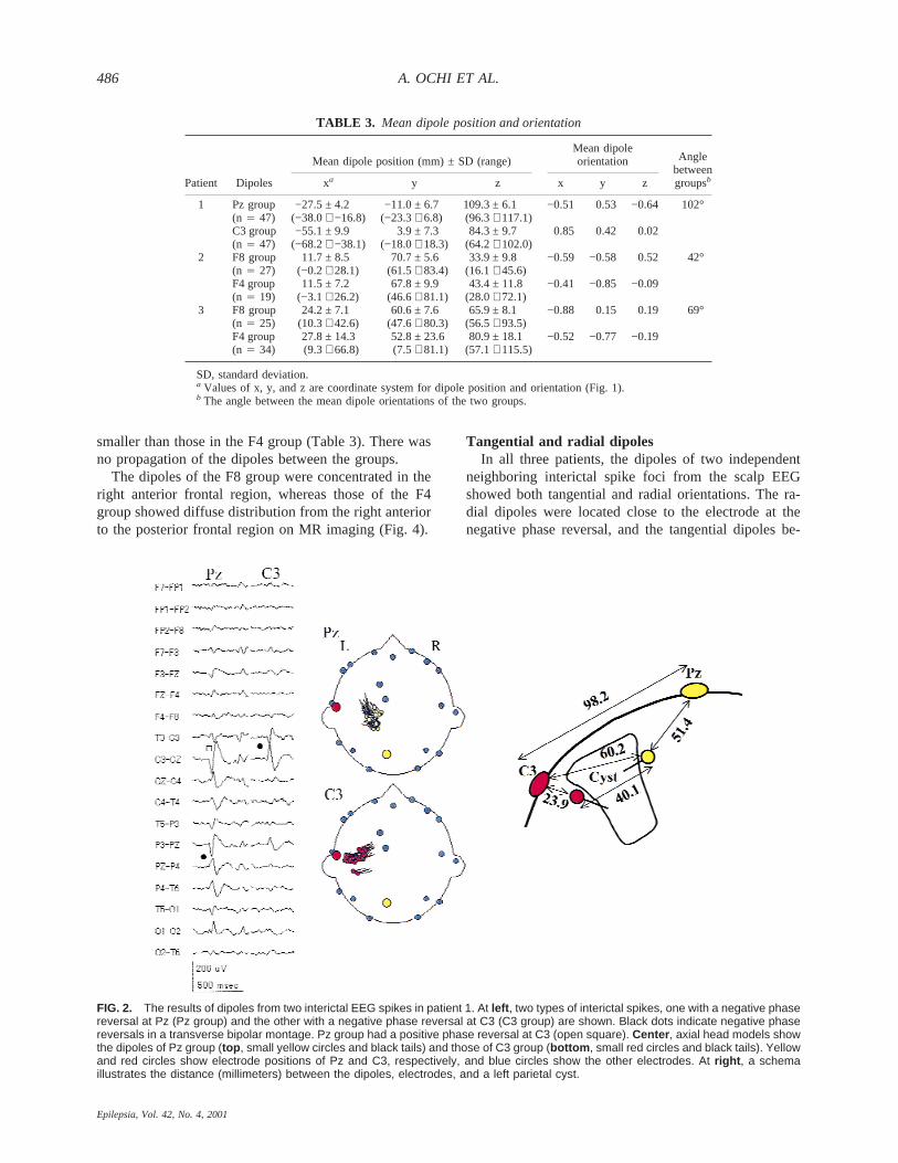
negative phase reversals at electrodes Pz and C3 in atransverse bipolar montage (Fig. 2). The spikes with anegative phase reversal at Pz (Pz group) had a positivephase reversal at C3 simultaneously. The dipoles of thePz group were located between electrodes Pz and C3 andoriented tangential to the scalp. The dipoles of the spikeswith a negative phase reversal at C3 (C3 group) wereclose to the electrode C3 and oriented radially (Fig. 2).Figure 2 (right) illustrates the distance between the elec-trodes and the dipoles. The SD of the dipole positionsfrom the Pz group was smaller than that from the C3group (Table 3).
The dipoles of the Pz group were located on the su-perior medial walls of the left parietal cyst, and those ofthe C3 group on the inferior lateral side of the wall on thecoregistered MR image.
In three of 17 Pz spikes, a negative maximum at Pzshifted to C3 15 ms after the Pz peak: these dipole po-sitions and orientations during propagation were identi-cal to those in the Pz to C3 group.
Patient 2In patient 2, the longitudinal bipolar montage EEG
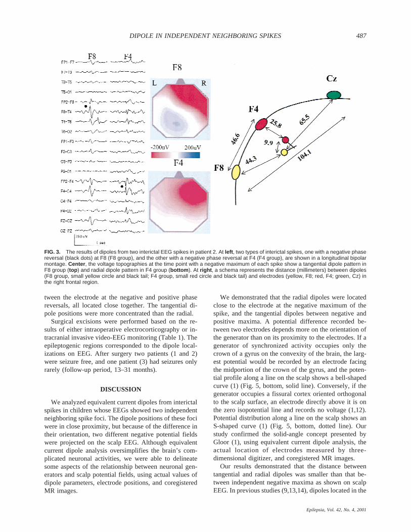
showed independent negative phase reversals at F8 andF4 (Fig. 3). The spikes with a negative phase reversal atF8 (F8 group) had a small positive polarity at Cz and Pzsimultaneously on the voltage topography, but this was
not clear on the bipolar montage EEG (Fig. 3, colorcontour map). The voltage topography of the spikes witha negative phase reversal at F4 (F4 group) showed asingle negative field. The mean dipole position of the F8group was remote from electrodes F8 and Cz, respec-tively, whereas that of the F4 group was close to elec-trode F4 (Fig. 3, right). The distance between the meandipole positions of each group was much shorter thanthat between electrodes F8 and F4. There was no propa-gation of dipoles between the two groups. The dipoles ineach group were stable and independent.
The dipoles of both F8 and F4 groups were localizedin the right frontal region on the coregistered MR image.
Patient 3In patient 3, the longitudinal bipolar montage EEG
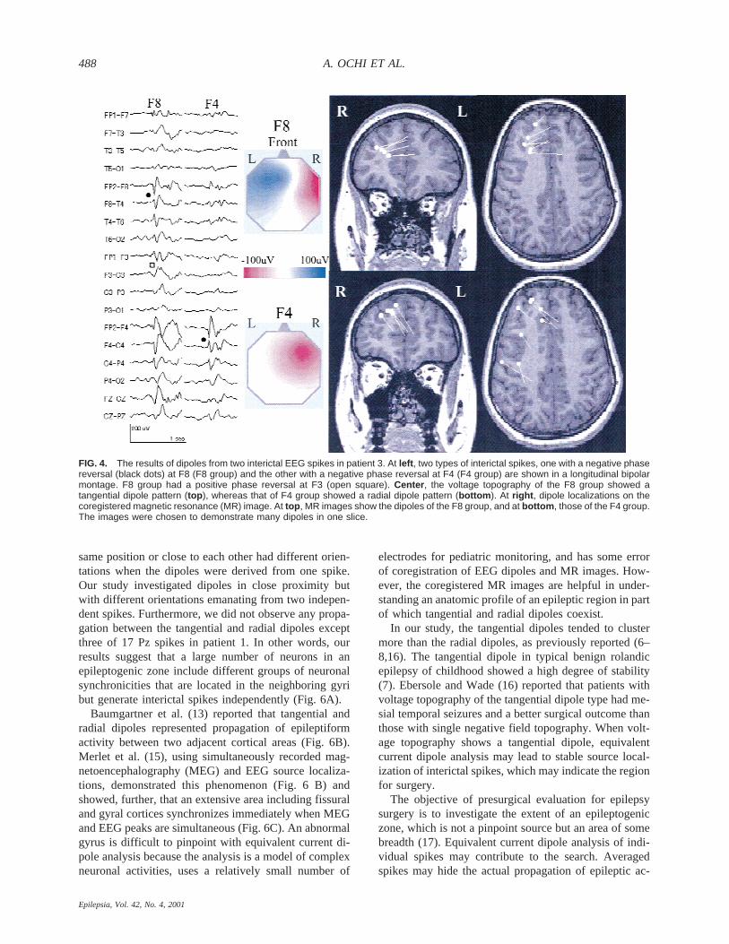
showed independent negative phase reversals at F8 andF4 (Fig. 4). The spikes with a negative phase reversal atF8 (F8 group) were accompanied by a positive phasereversal at F3. The voltage topography of the F8 groupshowed a tangential dipole pattern with a negative po-larity at right frontal region and a positive polarity at leftfrontal region, whereas that of the spikes with a negativephase reversal at F4 (F4 group) showed only a negativepolarity at right frontal region (Fig. 4, color contourmap). Five of 17 F4 spikes had a small positivity aroundelectrodes P4 or T6 on the voltage topography, in whichdipoles were located in the posterior frontal region (Fig.4, bottom axial MR image). The dipole of the F8 groupwas located between electrodes F3 and F8 and orientedtangential to the scalp, whereas that from F4 group wasclose to the electrode F4 and oriented radially (Fig. 5).The dipoles were located close to each other. The rangeand SD of the dipole position in the F8 group were
TABLE 1. Clinical profiles of three patients
Patient Age (y)MRI
findings Electrocorticography Dipole Surgical proceduresPathological
findingsOutcome
(follow-up period)
1 6 L–P cyst ECoG/L–P L–P Lesionectomy + MST Porencephalic cyst Sz-free (2 yr, 3 mo)2 15 Normal IVEEG/R–F, T, P R–F R–F, T, cortical excision + P, MST Gliosis Sz-free (2 yr, 7 mo)3 13 Normal IVEEG/R–F R–F R–F, cortical excision + MST Gliosis Rare Sz (13 mo)
L, left; R, right; P, parietal lobe; F, frontal lobe; T, temporal lobe; ECoG, intraoperative electrocorticography; IVEEG, intracranial invasive videoEEG monitoring; MST, multiple subpial transection; Sz, seizure; mo, months.
TABLE 2. Number of analyzed spikes and time points
Patient
Totalanalyzedspikes
Electrode atnegative phase
reversalNumberof spikes
Number ofspikes with
GoF > 95% (%)
Number ofanalyzed
time points
Number ofdipoles with
GoF > 95% (%)
1 37 Pz 17 17 (100) 697 47 (6.7)C3 20 20 (100) 820 47 (5.7)
2 62 F8 36 14 (38.9) 1476 27 (1.8)F4 26 9 (34.6) 1066 19 (1.8)
3 69 F8 23 14 (60.9) 943 25 (2.7)F4 46 17 (37.0) 1886 34 (1.8)
GoF, goodness of fit.
DIPOLE IN INDEPENDENT NEIGHBORING SPIKES 485
Epilepsia, Vol. 42, No. 4, 2001
smaller than those in the F4 group (Table 3). There wasno propagation of the dipoles between the groups.
The dipoles of the F8 group were concentrated in theright anterior frontal region, whereas those of the F4group showed diffuse distribution from the right anteriorto the posterior frontal region on MR imaging (Fig. 4).
Tangential and radial dipolesIn all three patients, the dipoles of two independent
neighboring interictal spike foci from the scalp EEGshowed both tangential and radial orientations. The ra-dial dipoles were located close to the electrode at thenegative phase reversal, and the tangential dipoles be-
TABLE 3. Mean dipole position and orientation
Patient Dipoles
Mean dipole position (mm) ± SD (range)Mean dipoleorientation Angle
betweengroupsbxa y z x y z
1 Pz group −27.5 ± 4.2 −11.0 ± 6.7 109.3 ± 6.1 −0.51 0.53 −0.64 102°(n 4 47) (−38.0∼ −16.8) (−23.3∼ 6.8) (96.3∼ 117.1)C3 group −55.1 ± 9.9 3.9 ± 7.3 84.3 ± 9.7 0.85 0.42 0.02(n 4 47) (−68.2∼ −38.1) (−18.0∼ 18.3) (64.2∼ 102.0)
2 F8 group 11.7 ± 8.5 70.7 ± 5.6 33.9 ± 9.8 −0.59 −0.58 0.52 42°(n 4 27) (−0.2∼ 28.1) (61.5∼ 83.4) (16.1∼ 45.6)F4 group 11.5 ± 7.2 67.8 ± 9.9 43.4 ± 11.8 −0.41 −0.85 −0.09(n 4 19) (−3.1∼ 26.2) (46.6∼ 81.1) (28.0∼ 72.1)
3 F8 group 24.2 ± 7.1 60.6 ± 7.6 65.9 ± 8.1 −0.88 0.15 0.19 69°(n 4 25) (10.3∼ 42.6) (47.6∼ 80.3) (56.5∼ 93.5)F4 group 27.8 ± 14.3 52.8 ± 23.6 80.9 ± 18.1 −0.52 −0.77 −0.19(n 4 34) (9.3∼ 66.8) (7.5∼ 81.1) (57.1∼ 115.5)
SD, standard deviation.a Values of x, y, and z are coordinate system for dipole position and orientation (Fig. 1).b The angle between the mean dipole orientations of the two groups.
FIG. 2. The results of dipoles from two interictal EEG spikes in patient 1. At left , two types of interictal spikes, one with a negative phasereversal at Pz (Pz group) and the other with a negative phase reversal at C3 (C3 group) are shown. Black dots indicate negative phasereversals in a transverse bipolar montage. Pz group had a positive phase reversal at C3 (open square). Center , axial head models showthe dipoles of Pz group (top , small yellow circles and black tails) and those of C3 group (bottom , small red circles and black tails). Yellowand red circles show electrode positions of Pz and C3, respectively, and blue circles show the other electrodes. At right , a schemaillustrates the distance (millimeters) between the dipoles, electrodes, and a left parietal cyst.
A. OCHI ET AL.486
Epilepsia, Vol. 42, No. 4, 2001
tween the electrode at the negative and positive phasereversals, all located close together. The tangential di-pole positions were more concentrated than the radial.
Surgical excisions were performed based on the re-sults of either intraoperative electrocorticography or in-tracranial invasive video-EEG monitoring (Table 1). Theepileptogenic regions corresponded to the dipole local-izations on EEG. After surgery two patients (1 and 2)were seizure free, and one patient (3) had seizures onlyrarely (follow-up period, 13–31 months).
DISCUSSION
We analyzed equivalent current dipoles from interictalspikes in children whose EEGs showed two independentneighboring spike foci. The dipole positions of these fociwere in close proximity, but because of the difference intheir orientation, two different negative potential fieldswere projected on the scalp EEG. Although equivalentcurrent dipole analysis oversimplifies the brain’s com-plicated neuronal activities, we were able to delineatesome aspects of the relationship between neuronal gen-erators and scalp potential fields, using actual values ofdipole parameters, electrode positions, and coregisteredMR images.
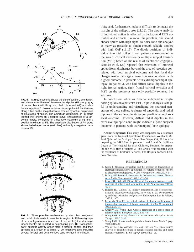
We demonstrated that the radial dipoles were locatedclose to the electrode at the negative maximum of thespike, and the tangential dipoles between negative andpositive maxima. A potential difference recorded be-tween two electrodes depends more on the orientation ofthe generator than on its proximity to the electrodes. If agenerator of synchronized activity occupies only thecrown of a gyrus on the convexity of the brain, the larg-est potential would be recorded by an electrode facingthe midportion of the crown of the gyrus, and the poten-tial profile along a line on the scalp shows a bell-shapedcurve (1) (Fig. 5, bottom, solid line). Conversely, if thegenerator occupies a fissural cortex oriented orthogonalto the scalp surface, an electrode directly above it is onthe zero isopotential line and records no voltage (1,12).Potential distribution along a line on the scalp shows anS-shaped curve (1) (Fig. 5, bottom, dotted line). Ourstudy confirmed the solid-angle concept presented byGloor (1), using equivalent current dipole analysis, theactual location of electrodes measured by three-dimensional digitizer, and coregistered MR images.
Our results demonstrated that the distance betweentangential and radial dipoles was smaller than that be-tween independent negative maxima as shown on scalpEEG. In previous studies (9,13,14), dipoles located in the
FIG. 3. The results of dipoles from two interictal EEG spikes in patient 2. At left , two types of interictal spikes, one with a negative phasereversal (black dots) at F8 (F8 group), and the other with a negative phase reversal at F4 (F4 group), are shown in a longitudinal bipolarmontage. Center , the voltage topographies at the time point with a negative maximum of each spike show a tangential dipole pattern inF8 group (top ) and radial dipole pattern in F4 group (bottom ). At right , a schema represents the distance (millimeters) between dipoles(F8 group, small yellow circle and black tail; F4 group, small red circle and black tail) and electrodes (yellow, F8; red, F4; green, Cz) inthe right frontal region.
DIPOLE IN INDEPENDENT NEIGHBORING SPIKES 487
Epilepsia, Vol. 42, No. 4, 2001
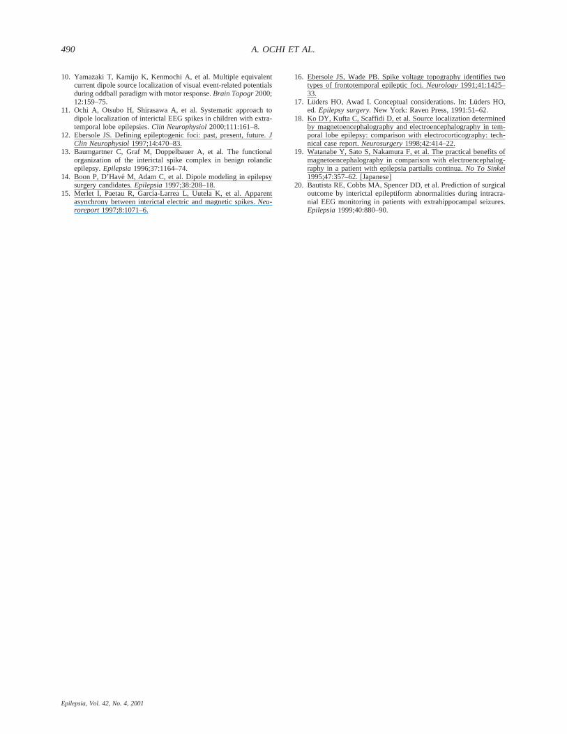
same position or close to each other had different orien-tations when the dipoles were derived from one spike.Our study investigated dipoles in close proximity butwith different orientations emanating from two indepen-dent spikes. Furthermore, we did not observe any propa-gation between the tangential and radial dipoles exceptthree of 17 Pz spikes in patient 1. In other words, ourresults suggest that a large number of neurons in anepileptogenic zone include different groups of neuronalsynchronicities that are located in the neighboring gyribut generate interictal spikes independently (Fig. 6A).
Baumgartner et al. (13) reported that tangential andradial dipoles represented propagation of epileptiformactivity between two adjacent cortical areas (Fig. 6B).Merlet et al. (15), using simultaneously recorded mag-netoencephalography (MEG) and EEG source localiza-tions, demonstrated this phenomenon (Fig. 6 B) andshowed, further, that an extensive area including fissuraland gyral cortices synchronizes immediately when MEGand EEG peaks are simultaneous (Fig. 6C). An abnormalgyrus is difficult to pinpoint with equivalent current di-pole analysis because the analysis is a model of complexneuronal activities, uses a relatively small number of
electrodes for pediatric monitoring, and has some errorof coregistration of EEG dipoles and MR images. How-ever, the coregistered MR images are helpful in under-standing an anatomic profile of an epileptic region in partof which tangential and radial dipoles coexist.
In our study, the tangential dipoles tended to clustermore than the radial dipoles, as previously reported (6–8,16). The tangential dipole in typical benign rolandicepilepsy of childhood showed a high degree of stability(7). Ebersole and Wade (16) reported that patients withvoltage topography of the tangential dipole type had me-sial temporal seizures and a better surgical outcome thanthose with single negative field topography. When volt-age topography shows a tangential dipole, equivalentcurrent dipole analysis may lead to stable source local-ization of interictal spikes, which may indicate the regionfor surgery.
The objective of presurgical evaluation for epilepsysurgery is to investigate the extent of an epileptogeniczone, which is not a pinpoint source but an area of somebreadth (17). Equivalent current dipole analysis of indi-vidual spikes may contribute to the search. Averagedspikes may hide the actual propagation of epileptic ac-
FIG. 4. The results of dipoles from two interictal EEG spikes in patient 3. At left , two types of interictal spikes, one with a negative phasereversal (black dots) at F8 (F8 group) and the other with a negative phase reversal at F4 (F4 group) are shown in a longitudinal bipolarmontage. F8 group had a positive phase reversal at F3 (open square). Center , the voltage topography of the F8 group showed atangential dipole pattern (top ), whereas that of F4 group showed a radial dipole pattern (bottom ). At right , dipole localizations on thecoregistered magnetic resonance (MR) image. At top , MR images show the dipoles of the F8 group, and at bottom , those of the F4 group.The images were chosen to demonstrate many dipoles in one slice.
A. OCHI ET AL.488
Epilepsia, Vol. 42, No. 4, 2001
tivity and, furthermore, make it difficult to delineate themargin of the epileptic area (11,18). The dipole analysisof individual spikes is affected by background EEG ac-tivities and artifacts. To solve this problem, one shouldchoose spikes with high signal-to-noise ratio and analyzeas many as possible to obtain enough reliable dipoleswith high GoF (11,19). The dipole positions of indi-vidual interictal spikes in our patients corresponded tothe area of cortical excision or multiple subpial transec-tion (MST) based on the results of electrocorticography.Bautista et al. (20) reported that extension of interictalepileptiform discharges beyond the area of resection cor-related with poor surgical outcome and that focal dis-charges inside the surgical resection area correlated witha good outcome in patients with extrahippocampal epi-lepsy. In patient 3, who had diffuse radial dipoles in theright frontal region, right frontal cortical excision andMST on the premotor area only partially relieved herseizures.
In conclusion, when we observe independent neigh-boring spikes on a patient’s EEG, dipole analysis is help-ful in understanding and visualizing the neuronal gen-erators of these spikes. A cluster of tangential and radialdipoles in the same epileptic region predicts a good sur-gical outcome. However, diffuse radial dipoles in theextensive epileptic zone might indicate a poor surgicaloutcome in patients with extratemporal lobe epilepsy.
Acknowledgment: This study was supported by a researchgrant from the National Epifellows Foundation. We thank Ms.Patti Quint of the Scripps Clinic (San Diego, CA, U.S.A.) forpreparing the MRI files in patients 1 and 2 and Dr. WilliamLogan of The Hospital for Sick Children, Toronto, for prepar-ing the MRI files of patient 3. This article was prepared withthe assistance of Editorial Services, The Hospital for Sick Chil-dren, Toronto.
REFERENCES
1. Gloor P. Neuronal generators and the problem of localization inelectroencephalography: application of volume conductor theoryto electroencephalography.J Clin Neurophysiol1985;2:327–54.
2. Bishop GH. Potential phenomena in thalamus and cortex.Electro-enceph clin Neurophysiol1949;1:421–36.
3. Lesser RP, Lu¨ders H, Dinner DS, et al. An introduction to the basicconcepts of polarity and localization.J Clin Neurophysiol1985;2:45–61.
4. Burgess RC, Collura TF. Polarity, localization, and field determi-nation in electroencephalography. In: Wyllie E, ed.The treatmentof epilepsy: principles and practice.Philadelphia: Lea & Febiger,1993:211–33.
5. Lopes da Silva FH. A critical review of clinical applications oftopographic mapping of brain potentials.J Clin Neurophysiol1990;7:535–51.
6. Gregory DL, Wong PKH. Clinical relevance of a dipole field inrolandic spikes.Epilepsia1992;33:36–44.
7. Wong PKH. Stability of source estimates in rolandic spikes.BrainTopogr1989;2:31–6.
8. Wong PKH. Source modeling of the rolandic focus.Brain Topogr1991;4:105–12.
9. Van der Meij W, Wieneke GH, Van Huffelen AC. Dipole sourceanalysis of rolandic spikes in benign rolandic epilepsy and otherclinical syndromes.Brain Topogr1993;5:203–13.
FIG. 6. Three possible mechanisms by which both tangentialand radial dipoles exist in an epileptic region. A: Different groupsof neuronal generators (open and closed circles) that dischargeindependently are located in neighboring gyri. B: Propagation:early epileptic activity arises from a fissural cortex, and thenspreads to a crown of a gyrus. C: An extensive area includingseveral fissural and gyral cortices synchronizes immediately.
FIG. 5. At top , a schema shows the dipole position, orientation,and distance (millimeters) between the dipoles (F8 group, graycircle and black tail; F4 group, black circle and tail) and elec-trodes in patient 3. Lower schema shows potential distributionsalong a line on the scalp that were created by actual amplitudesat electrodes of spikes. The amplitude distribution of F8 group(dotted line) shows an S-shaped curve, characteristic of a tan-gential dipole, consisting of a negative maximum at F8 and apositive maximum at F3. The amplitude distribution of F4 groupshows bell-shaped curve (solid line) with only a negative maxi-mum at F4.
DIPOLE IN INDEPENDENT NEIGHBORING SPIKES 489
Epilepsia, Vol. 42, No. 4, 2001
10. Yamazaki T, Kamijo K, Kenmochi A, et al. Multiple equivalentcurrent dipole source localization of visual event-related potentialsduring oddball paradigm with motor response.Brain Topogr2000;12:159–75.
11. Ochi A, Otsubo H, Shirasawa A, et al. Systematic approach todipole localization of interictal EEG spikes in children with extra-temporal lobe epilepsies.Clin Neurophysiol2000;111:161–8.
12. Ebersole JS. Defining epileptogenic foci: past, present, future.JClin Neurophysiol1997;14:470–83.
13. Baumgartner C, Graf M, Doppelbauer A, et al. The functionalorganization of the interictal spike complex in benign rolandicepilepsy.Epilepsia1996;37:1164–74.
14. Boon P, D’Have´ M, Adam C, et al. Dipole modeling in epilepsysurgery candidates.Epilepsia1997;38:208–18.
15. Merlet I, Paetau R, Garcı´a-Larrea L, Uutela K, et al. Apparentasynchrony between interictal electric and magnetic spikes.Neu-roreport 1997;8:1071–6.
16. Ebersole JS, Wade PB. Spike voltage topography identifies twotypes of frontotemporal epileptic foci.Neurology1991;41:1425–33.
17. Luders HO, Awad I. Conceptual considerations. In: Lu¨ders HO,ed.Epilepsy surgery.New York: Raven Press, 1991:51–62.
18. Ko DY, Kufta C, Scaffidi D, et al. Source localization determinedby magnetoencephalography and electroencephalography in tem-poral lobe epilepsy: comparison with electrocorticography: tech-nical case report.Neurosurgery1998;42:414–22.
19. Watanabe Y, Sato S, Nakamura F, et al. The practical benefits ofmagnetoencephalography in comparison with electroencephalog-raphy in a patient with epilepsia partialis continua.No To Sinkei1995;47:357–62. [Japanese]
20. Bautista RE, Cobbs MA, Spencer DD, et al. Prediction of surgicaloutcome by interictal epileptiform abnormalities during intracra-nial EEG monitoring in patients with extrahippocampal seizures.Epilepsia1999;40:880–90.
A. OCHI ET AL.490
Epilepsia, Vol. 42, No. 4, 2001