design of shading screens inspired by persian geometric patterns: an integrated structural and...
TRANSCRIPT

Proceedings of the IASS-SLTE 2014 Symposium“Shells, Membranes and Spatial Structures: Footprints”
15 to 19 September 2014, Brasilia, BrazilReyolando M.L.R.F. BRASIL and Ruy M.O. PAULETTI (eds.)
Copyright © 2014 by the authors.Published by the International Association for Shell and Spatial Structures (IASS) with permission. 1
Design of Shading Screen Inspired by Persian GeometricPatterns: An Integrated Structural and Daylighting
Performance Evaluation
Niloufar EMAMI*, Anahita KHODADADI a, Peter VON BUELOWb,
*University of Michigan2000 Bonisteel Blvd., Ann Arbor, MI, 48109
a , b University of Michigan
[email protected] , [email protected]
AbstractShading screens have been used as daylight control systems, which also play a role as design elements oftransparent facades. A façade’s configuration can be an explicit representation of its functions. There aremultiple functions within a building and sometimes a dominant function imposes one configuration to the wholesystem; in this case, a replicated geometry that is used for the shading screen. In contrast, by grading the screen’sgeometry, there is a response to each individual programmatic function according to the interior space of thebuilding [1].We propose a functionally graded shading system that responses to different programmatic buildingfunctions. In this study, some geometric patterns, widely used in Persian historical ornamentations, have beenchosen as the underlying geometry for shading screens.
Geometric ornamental patterns are based on mathematical concepts, which are implemented on regular shapes ofa certain arrangement. In general, such configurations have three geometric characteristics that have raised thetendency of employing the geometric patterns in ornaments of shading screens, facades, floor finishing andwindows of both historical and contemporary architecture. First, these patterns can be fitted on different surfacesthrough geometrical concepts such as propagation, curtailment and scaling. Second, most of these types ofpatterns are self-similar configurations that are roughly similar to one part of themselves. This characteristicassists in making use of the properties of fractal geometry in parametric design of the patterns and furthermodification of an arrangement and density of a typical configuration. Third, some different patterns aregenerally based upon the same underlying rules and can be generated using almost the same geometricalprocessing techniques. Considering the self-similarity characteristic of the patterns, some shading screens aredesigned in this study with some Persian geometric patterns and then they are evaluated regarding theirdaylighting and structural performance.
In the daylighting performance evaluation phase, we look at the year around daylighting levels and lightdistribution of a regular office space, while the specified shading screen is installed in front of a transparent fullfloor to ceiling glass facade. It is assumed that by using the shading screen, the required lighting levels are beingmaintained, while the heat gain is being reduced. In addition, the designed patterns play a role as an architecturalfeature of the building.
In the structural performance evaluation phase, the shading screens which are considered as exterior self-supporting systems are analyzed under their self-weight and wind loads. The goal is to reach a minimum weightfor the screens that are performing structurally.
Ultimately, the presented shading screens are based on Persian geometric ornamental patterns and arrangedaccording to the lighting and structural requirements. Results are indicating a multi-disciplinary approach in thedesign of the shading screens, which can be employed in creating similar prototypes with different climatic andloading requirements.
Keywords: Shading screens, Persian ornamentation patterns, Performance-based design, Daylightingperformance, Structural performance
Proceedings of the IASS-SLTE 2014 Symposium“Shells, Membranes and Spatial Structures: Footprints”
Copyright © 2014 by the author(s).Published by the International Association for Shell and Spatial Structures (IASS) with permission.
1. IntroductionThis study looks at the design of shading screens that are inspired by Persian geometric ornamentation patterns.Shading screens are defined as external perforated panels that are fixed in front of windows. We define shadingscreen as a self-supporting wall system that is located in front of a full floor to ceiling window. The goal of thestudy is to look at the interaction of variables and effect of the geometrical parameters of the perforated screenwall on the day-lighting performance of the space as well as the structural performance of the wall itself. Therelation between form and structure has been well researched in the literature and realized projects. Also, theeffect of form on daylighting performance has been researched in the environmental technology area. In a studycarried out by Sherif et al., he studied different perforation percentages of screen walls and simulated thedaylighting levels of the residential space. [2] The aim of this interdisciplinary, multi-objective research is tostudy the interrelated aspects of structural and daylighting performance with geometry, in order to aid thedesigner to understand the effects of decision making on various performance aspects of the design.
This research consists of two main phases, and each phase is divided in to daylighting and structuralperformance evaluation. In the first phase of this study, four possible configurations have been opted for (basedon a parametric design), and their performance has been individually evaluated; then the results are compared.The second phase adopts an evolutionary method, Genetic Algorithms (GA), which is a population-basedoptimization method. In this stage, pallets of possible design alternatives coupled with their relativeperformances are generated. The criteria for evaluating different designs can be set according to the indices likeminimum weight, maximum daylighting levels, least deformation, etc.
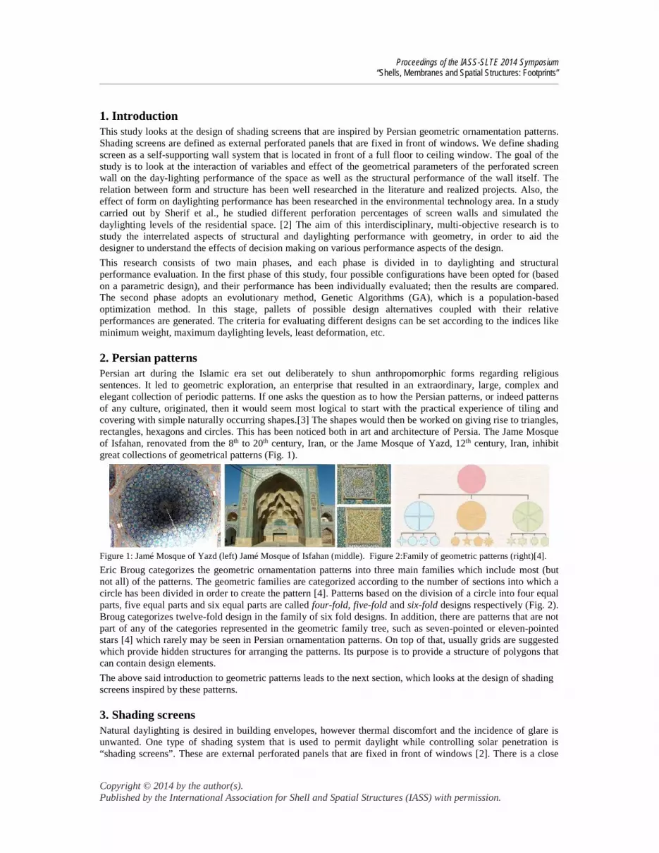
2. Persian patternsPersian art during the Islamic era set out deliberately to shun anthropomorphic forms regarding religioussentences. It led to geometric exploration, an enterprise that resulted in an extraordinary, large, complex andelegant collection of periodic patterns. If one asks the question as to how the Persian patterns, or indeed patternsof any culture, originated, then it would seem most logical to start with the practical experience of tiling andcovering with simple naturally occurring shapes.[3] The shapes would then be worked on giving rise to triangles,rectangles, hexagons and circles. This has been noticed both in art and architecture of Persia. The Jame Mosqueof Isfahan, renovated from the 8th to 20th century, Iran, or the Jame Mosque of Yazd, 12th century, Iran, inhibitgreat collections of geometrical patterns (Fig. 1).
Figure 1: Jamé Mosque of Yazd (left) Jamé Mosque of Isfahan (middle). Figure 2:Family of geometric patterns (right)[4].
Eric Broug categorizes the geometric ornamentation patterns into three main families which include most (butnot all) of the patterns. The geometric families are categorized according to the number of sections into which acircle has been divided in order to create the pattern [4]. Patterns based on the division of a circle into four equalparts, five equal parts and six equal parts are called four-fold, five-fold and six-fold designs respectively (Fig. 2).Broug categorizes twelve-fold design in the family of six fold designs. In addition, there are patterns that are notpart of any of the categories represented in the geometric family tree, such as seven-pointed or eleven-pointedstars [4] which rarely may be seen in Persian ornamentation patterns. On top of that, usually grids are suggestedwhich provide hidden structures for arranging the patterns. Its purpose is to provide a structure of polygons thatcan contain design elements.
The above said introduction to geometric patterns leads to the next section, which looks at the design of shadingscreens inspired by these patterns.
3. Shading screensNatural daylighting is desired in building envelopes, however thermal discomfort and the incidence of glare isunwanted. One type of shading system that is used to permit daylight while controlling solar penetration is“shading screens”. These are external perforated panels that are fixed in front of windows [2]. There is a close

Proceedings of the IASS-SLTE 2014 Symposium“Shells, Membranes and Spatial Structures: Footprints”
Copyright © 2014 by the author(s).Published by the International Association for Shell and Spatial Structures (IASS) with permission.
connection between the geometric patterns and the design of shading screens, as the two dimensional patternsthat were recognized by color and material in tiling of the buildings, evolve as three dimensional screens whichplay a role as daylight control systems. (Fig. 3).
Within the Middle East, historical examples of shading screens are wooden balconies, known as “Shanāsheel”,and blinding unglazed latticeworks called “Shobāk”, and both control view and daylight (Fig. 4). An additionaladvantage of these screens lies in their provision of privacy, which is a social-cultural need in its original region[2]. In tropical regions of Iran especially in Bushehr city, Shanāsheel played a role in providing view and light aswell as natural ventilation for the buildings.
During the past decade the traditional patterns of shading screens has been transformed to new patterns, byvarying some of the basic mathematical rules like symmetry of the patterns or equal dimension of a replicatedgeometry. Furthermore, some active solar screens with such patterns has been developed.
A notable example in Middle East region in this regard is Masdar City, designed by Foster and Partners. The cityis designed to encourage walking, while its shaded streets and courtyards offer an attractive pedestrianenvironment, sheltered from climatic extremes [5]. The undulating residential building facades have an externalscreen with a pattern that is inspired by traditional latticework (Fig. 5)[6].
Another example is The New Headquarters of the Abu Dhabi Investment with a diaphanous screen that is in theform of a dynamic latticework, for the Al Bahr Towers. This is opened and closed in response to the sun’s path(Fig. 6), and reduces the solar heat gain significantly to provide a more comfortable internal environment. Thefacade is computer controlled and is made of more than two thousand translucent, parasol-like units that areopened and closed as the sun moves over their surface [7]. This active shading screen can be considered as areinterpretation of the carved and perforated screens that traditionally provided shade and privacy to MiddleEastern homes.
Figure 5: Residential buildings of Masdar City, [6] Figure 6: The dynamic shading of Al Bahr Towers, [7]
These examples indicate a re-interpretation of the traditional geometric patterns as shading screens that has led todesign of new geometric patterns albeit based on the unchanged fundamental principles.
4. Configuration processing of a Persian geometric ornamentation patternBased on the six-fold design, a basic pattern was designed and then replicated in the plane. A hexagonal gridwith a radius of 35 cm was the underlying grid of the pattern. After the basic diamond pattern was designed, thediamonds were offset towards inside in order to create apertures. The offset value is dependent on the distancebetween hexagon’s centers and a defined attraction point (Fig. 7).
To design the geometric patterns, Rhino has been opted as the modeling platform and Grasshopper, which is aparametric modeling plugin for Rhino, has been used. Grasshopper provides the opportunity to parametricallydesign and then alter the variables, in order to create various iterations of the design downstream. The constantand variable parameters and their acceptable intervals that are used for design are described in Fig. 8.
Figure 3: The shading screens,“Shobāk”, in Jame Moque of Isfahan
Figure 4: Shanāsheel, Taheri House (left) and Deyri House (middle) inBushehr, Iran. A house in Basreh, Iraq (right), [5]

Proceedings of the IASS-SLTE 2014 Symposium“Shells, Membranes and Spatial Structures: Footprints”
Copyright © 2014 by the author(s).Published by the International Association for Shell and Spatial Structures (IASS) with permission.
Figure 8: Geometric parameters on which the configuration processing of shading screens are based.
Parameter Symbol Constant/ variable Acceptable interval
Width of the screen W Constant 500 cm
Height of the screen H Constant 500 cm
Depth of the screen D Variable [5-35 centimeter] step 5cm
Hexagonal grid radius Grid Constant 35
Diamond diagonal dimensions Diamond Constant 35 * 61
Division Distance (the distance from attractionpoint is divided by this value)
Div. Dist. Variable [1-110] step 1
Radius of the wall’s curvature R Constant 4819 cm
Center location of the subtracted curve Center Variable in y axis
Variable in z axis
[0- 36] step 1
[0- 500] step 1
From another point of view, the wall has a depth varying from 5 to 35 centimeters while a circle with a radius of4819 cm is subtracted from the backside of the wall. The placement of the circle’s center varies and can beshifted across the z-y plane. This creates a curved section on one side of the wall in case the circle intersects withthe wall. There is also the possibility that the circle does not cross the wall which results a straight section withno curvature. (Fig. 9) The final step is subtracting the pattern from the wall. It was initially assumed that the wallwith maximum width at bottom and minimum width at top is the most efficient configuration structurally; andthe wall with maximum width at top and minimum width at bottom is the most efficient configuration in termsof daylighting, since it will reflect light and act as a light shelve. The purpose was to look at the tradeoff amongthese two aspects. (Fig. 9)
This pattern provides the opportunity that the size and ratio of the apertures change, which leads to a change inthe perforation ratio of the screen. This ultimately affects the daylight illumination. On the other hand, thisaffects the weight and the structural performance of the wall. The relation between daylighting performance andstructural performance is defined in Fig. 10.
Figure 10: The effects of different parameters on daylighting and structural performance
Parameter Effect on daylighting performance Effect on structural performance
Depth of the screen Daylight illumination (lux) Weight of the screen, deformation
Perforation ratio Daylight illumination (lux) Weight of the screen, local stresses
Sectional subtracted curve Light shelf effect, overhang effect Changes the centroid of the structure
4.1. Design of experimentsIn the first phase of the study, four different configurations were generated and then the simulations wereconducted. All configurations have a curved surface on the back side of the wall. In two configurations, themaximum thickness occurs in the base (31 cm) while it reaches the minimum thickness at the head (5 cm). In theother two configurations, this is mirrored. Then two different perforation ratios are applied to each case. (54%perforation ratio with Div. Dist. of 90 and 35% perforation ration with Div. Dist. of 44). The design of theexperiments is graphically illustrated in Fig. 11.
Figure 7: The basic pattern for the shading screen Figure 9: the assumed efficient wall in terms of daylight(left), the assumed efficient wall in terms of structuralperformance (right)

Proceedings of the IASS-SLTE 2014 Symposium“Shells, Membranes and Spatial Structures: Footprints”
Copyright © 2014 by the author(s).Published by the International Association for Shell and Spatial Structures (IASS) with permission.
4.2. Architectural applicationsThese screen walls have the potential to be stacked on top of each other to create a perforated screen wall in frontof a glass façade. This provides the opportunity to change the perforation ratio of each module depending on thespecific program of the space and the required daylighting levels of that space.[1] In addition, the screen wall hasthe potential to be more integrated with the main structure of the building by connecting to the slabs from topand bottom, in order to transfer structural loads to the ground. (Fig. 12) On top of this, the screen walls canchange their role from shading screen to the main building facade, by placing the glass panes in the aperturesinstead of adding a layer to the glass envelope.
5. Daylighting performanceThe designed shading screen is applied to a base case open-plan office space with minimum 500 lux illuminationdaylighting requirement [8]. The location has been defined as a cooling dominant location, Phoenix, AZ(33.45°N and 111.98°E). The buildings in this area receive extensive sunlight which requires to be mediated inorder to reduce the heat gains. Maximum sun altitude at solar noon on the first day of summer equals to 80.05(90 -33.45 +23.5) and maximum sun altitude at solar noon on the first day of winter equals to 33.05 (90 -33.45 -23.5). This office measures 5 m wide, 5 m high and 7.5 m deep, and the only window of this space is a full floorto ceiling south oriented window. The reference plane on which daylighting performance was simulated is a gridat a working plane of 90cm height. (Fig. 13)
5.1. DIVA-for-RhinoSince Rhinoceros has been chosen as the modeling platform, DIVA-for-Rhino, which is a highly optimizeddaylighting and energy modeling plug-in for Rhino, has been chosen for daylighting simulations. This alsoavoids geometry transfer between different software. The simulations in DIVA are based on powerfulenvironmental performance engines such as Radiance, Daysim and Energy Plus.[9] Phoenix, Arizona has beenopted as the location and the clear sky with sun has been set to be the sky-type. The default DIVA materials havebeen assigned to the geometry including Generic Floor (20), Generic interior walls (50), High reflectance ceiling(90), Outside ground (20), Glazing single pane (88) and Outside Facade (35). The setting parameters were set toab 2, ad 1000, as 20, ar 300.Year round performance is addressed by using a Dynamic Daylight Performance Metrics (DDPMs). [2] Climate-Based Metrics use recorded data in the form of *.epw files to simulate the sun and sky conditions for varioussimulations including “Daylight Autonomy”. The important aspect of Climate-Based Metrics is that they areannual calculations which mean they take the entire year into account. [9] The “Daylight Autonomy” index (DA)is defined as the percentage of the occupied hours of the year when a minimum illuminance threshold is met bydaylight alone.[2] Therefore if a space with 500 lux requirement had a DA of 80%, it means that the requiredlighting level would be met by daylight alone, in 80% of the year; and the artificial lighting must be used for theremaining percentage. It is assumed that this space will be occupied weekdays from 9 am until 5 pm with thetotal annual hours of occupancy of 1827 hours per year. There is no active lighting control or dynamic shadingsystem in the scene.All four configurations have been simulated and the results have been compared with a base case model with noshading screen. The aim of this stage is to evaluate the effect of changing the Shading Screen perforationpercentage and wall curvature on annual performance, in order to conclude the best coupled curvature andperforation percentage.
Figure 12: Architecturalapplication: stackedpanels connected to slabs.
Figure 13: Assumed designparameters of the office space.
Figure 11: Design of Experiments.
Proceedings of the IASS-SLTE 2014 Symposium“Shells, Membranes and Spatial Structures: Footprints”
Copyright © 2014 by the author(s).Published by the International Association for Shell and Spatial Structures (IASS) with permission.
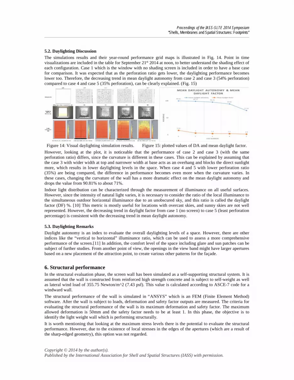
5.2. Daylighting DiscussionThe simulations results and their year-round performance grid maps is illustrated in Fig. 14. Point in timevisualizations are included in the table for September 21st 2014 at noon, to better understand the shading effect ofeach configuration. Case 1 which is the window with no shading screen is included in order to have a base casefor comparison. It was expected that as the perforation ratio gets lower, the daylighting performance becomeslower too. Therefore, the decreasing trend in mean daylight autonomy from case 2 and case 3 (54% perforation)compared to case 4 and case 5 (35% perforation), can be clearly explained. (Fig. 15)
Figure 14: Visual daylighting simulation results. Figure 15: plotted values of DA and mean daylight factor.
However, looking at the plot, it is noticeable that the performance of case 2 and case 3 (with the sameperforation ratio) differs, since the curvature is different in these cases. This can be explained by assuming thatthe case 3 with wider width at top and narrower width at base acts as an overhang and blocks the direct sunlightmore, which results in lower daylighting levels in the space. When case 4 and 5 with lower perforation ratio(35%) are being compared, the difference in performance becomes even more when the curvature varies. Inthese cases, changing the curvature of the wall has a more dramatic effect on the mean daylight autonomy anddrops the value from 90.81% to about 71%.
Indoor light distribution can be characterized through the measurement of illuminance on all useful surfaces.However, since the intensity of natural light varies, it is necessary to consider the ratio of the local illuminance tothe simultaneous outdoor horizontal illuminance due to an unobscured sky, and this ratio is called the daylightfactor (DF) %. [10] This metric is mostly useful for locations with overcast skies, and sunny skies are not wellrepresented. However, the decreasing trend in daylight factor from case 1 (no screen) to case 5 (least perforationpercentage) is consistent with the decreasing trend in mean daylight autonomy.
5.3. Daylighting RemarksDaylight autonomy is an index to evaluate the overall daylighting levels of a space. However, there are otherindices like the “vertical to horizontal” illuminance ratio, which can be used to assess a more comprehensiveperformance of the screen.[11] In addition, the comfort level of the space including glare and sun patches can besubject of further studies. From another point of view, the openings in the view band might have larger aperturesbased on a new placement of the attraction point, to create various other patterns for the façade.
6. Structural performanceIn the structural evaluation phase, the screen wall has been simulated as a self-supporting structural system. It isassumed that the wall is constructed from reinforced high strength concrete and is subject to self-weight as wellas lateral wind load of 355.75 Newton/m^2 (7.43 psf). This value is calculated according to ASCE-7 code for awindward wall.
The structural performance of the wall is simulated in “ANSYS” which is an FEM (Finite Element Method)software. After the wall is subject to loads, deformation and safety factor outputs are measured. The criteria forevaluating the structural performance of the wall is its maximum deformation and safety factor. The maximumallowed deformation is 50mm and the safety factor needs to be at least 1. In this phase, the objective is toidentify the light weight wall which is performing structurally.
It is worth mentioning that looking at the maximum stress levels there is the potential to evaluate the structuralperformance. However, due to the existence of local stresses in the edges of the apertures (which are a result ofthe sharp-edged geometry), this option was not regarded.
Proceedings of the IASS-SLTE 2014 Symposium“Shells, Membranes and Spatial Structures: Footprints”
Copyright © 2014 by the author(s).Published by the International Association for Shell and Spatial Structures (IASS) with permission.
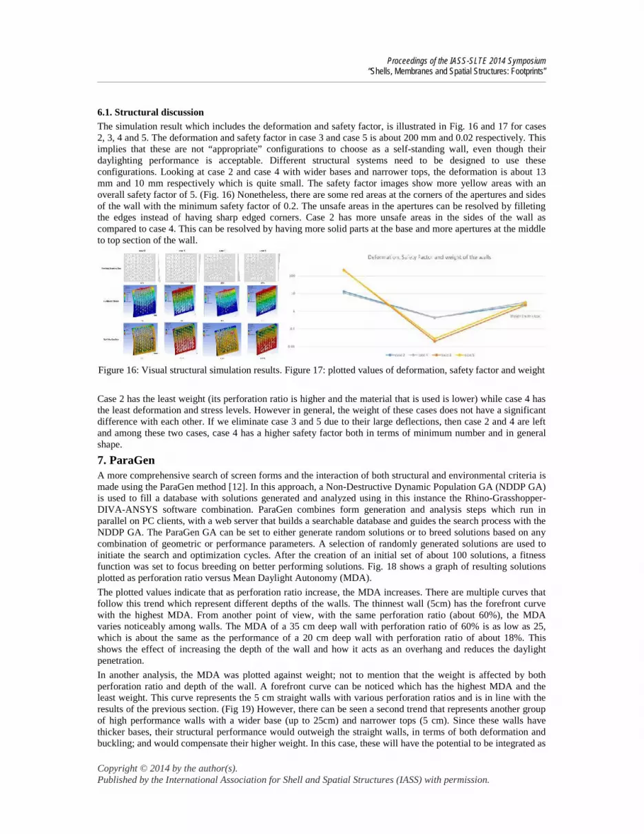
6.1. Structural discussionThe simulation result which includes the deformation and safety factor, is illustrated in Fig. 16 and 17 for cases2, 3, 4 and 5. The deformation and safety factor in case 3 and case 5 is about 200 mm and 0.02 respectively. Thisimplies that these are not “appropriate” configurations to choose as a self-standing wall, even though theirdaylighting performance is acceptable. Different structural systems need to be designed to use theseconfigurations. Looking at case 2 and case 4 with wider bases and narrower tops, the deformation is about 13mm and 10 mm respectively which is quite small. The safety factor images show more yellow areas with anoverall safety factor of 5. (Fig. 16) Nonetheless, there are some red areas at the corners of the apertures and sidesof the wall with the minimum safety factor of 0.2. The unsafe areas in the apertures can be resolved by filletingthe edges instead of having sharp edged corners. Case 2 has more unsafe areas in the sides of the wall ascompared to case 4. This can be resolved by having more solid parts at the base and more apertures at the middleto top section of the wall.
Figure 16: Visual structural simulation results. Figure 17: plotted values of deformation, safety factor and weight
Case 2 has the least weight (its perforation ratio is higher and the material that is used is lower) while case 4 hasthe least deformation and stress levels. However in general, the weight of these cases does not have a significantdifference with each other. If we eliminate case 3 and 5 due to their large deflections, then case 2 and 4 are leftand among these two cases, case 4 has a higher safety factor both in terms of minimum number and in generalshape.
7. ParaGenA more comprehensive search of screen forms and the interaction of both structural and environmental criteria ismade using the ParaGen method [12]. In this approach, a Non-Destructive Dynamic Population GA (NDDP GA)is used to fill a database with solutions generated and analyzed using in this instance the Rhino-Grasshopper-DIVA-ANSYS software combination. ParaGen combines form generation and analysis steps which run inparallel on PC clients, with a web server that builds a searchable database and guides the search process with theNDDP GA. The ParaGen GA can be set to either generate random solutions or to breed solutions based on anycombination of geometric or performance parameters. A selection of randomly generated solutions are used toinitiate the search and optimization cycles. After the creation of an initial set of about 100 solutions, a fitnessfunction was set to focus breeding on better performing solutions. Fig. 18 shows a graph of resulting solutionsplotted as perforation ratio versus Mean Daylight Autonomy (MDA).
The plotted values indicate that as perforation ratio increase, the MDA increases. There are multiple curves thatfollow this trend which represent different depths of the walls. The thinnest wall (5cm) has the forefront curvewith the highest MDA. From another point of view, with the same perforation ratio (about 60%), the MDAvaries noticeably among walls. The MDA of a 35 cm deep wall with perforation ratio of 60% is as low as 25,which is about the same as the performance of a 20 cm deep wall with perforation ratio of about 18%. Thisshows the effect of increasing the depth of the wall and how it acts as an overhang and reduces the daylightpenetration.
In another analysis, the MDA was plotted against weight; not to mention that the weight is affected by bothperforation ratio and depth of the wall. A forefront curve can be noticed which has the highest MDA and theleast weight. This curve represents the 5 cm straight walls with various perforation ratios and is in line with theresults of the previous section. (Fig 19) However, there can be seen a second trend that represents another groupof high performance walls with a wider base (up to 25cm) and narrower tops (5 cm). Since these walls havethicker bases, their structural performance would outweigh the straight walls, in terms of both deformation andbuckling; and would compensate their higher weight. In this case, these will have the potential to be integrated as

Proceedings of the IASS-SLTE 2014 Symposium“Shells, Membranes and Spatial Structures: Footprints”
Copyright © 2014 by the author(s).Published by the International Association for Shell and Spatial Structures (IASS) with permission.
structural elements in buildings. In addition, the curvature provides the opportunity for designers to bring varietyto the performative screen walls, not only with varying geometrical perforations, but also with altering the form.
Figure 18: MDA versus perforation ratio Figure 19: MDA versus Weight
8. ConclusionThis research looks at a multi-objective performance evaluation of a screen wall, inspired by Persian geometricpatterns. The study contributes to the design of screen walls, in order to control daylighting and to provideshading for the buildings. The loadbearing capacity of the wall provides the opportunity to be used as a self-standing building envelope. The modules of the screen wall can be stacked on top of each other to shield amulti-story building, which expands the boundaries of its application. In this case, the screen wall is no longerself-standing and needs to be integrated with the structure of the building. The perforation ratio of each modulecan differ to accommodate the unique daylighting needs of a specific space. The depth and curvature of the wallcan vary depending on the required structural behavior, which ultimately affects the weight of the wall. From theconstruction point of view, since the screen wall is constructed from concrete, a minimum width of 2.5 cm (1inch) must be considered for the apertures divider. Designers can bring variety to the design of screen walls, notonly with varying geometrical perforations, but also with altering the curvature.
AcknowledgementHere, authors wish to thank Professor Harry Giles from the University of Michigan for his support, and alsoProfessor Mojtaba Navvab and Professor Jong-Jin Kim from the University of Michigan for their suggestions.
References[1] N. Emami and H. Giles, “Engineering without the engine: An integrated panelized passive shading system for
transparent façades,” in ARCC (The Architectural Research Centers Consortium), 2014.[2] A. Sherif, H. Sabry, and T. Rakha, “External perforated Solar Screens for daylighting in residential desert buildings:
Identification of minimum perforation percentages,” Sol. Energy, vol. 86, no. 6, pp. 1929–1940, Jun. 2012.[3] S. J. Abas and a. Salman, “Geometric and Group-theoretic Methods for Computer Graphic Studies of Islamic
Symmetric Patterns,” Comput. Graph. Forum, vol. 11, no. 1, pp. 43–53, Jan. 1992.[4] E. Broug, Islamic geometric design. Thames & Hudson, 2013.[5] N. Ouroussoff, “In Arabian Desert , a Sustainable City Rises,” The NewYork Times, 25-Sep-2010.[6] P. Patel, “Masdar City showcases sustainability,” Energy Q., vol. 38, no. June, pp. 450–451, 2013.[7] N. Council and T. M. Teacher, “Shining the Light on Mathematics,” vol. 107, no. 4, pp. 252–256, 2014.[8] Illuminating Engineering Society of North America, The IESNA lighting handbook, 9th ed. NewYork, 2000.[9] C. Reinhart and et al, “DIVA-for-Rhino.” [Online]. Available: http://diva4rhino.com/. [Accessed: 17-Apr-2014].[10] M. Fontoyont, Daylight performance of buildings. London: James & James, 1999.[11] J. A. Love and M. Navvab, “The Vertical-to-Horizontal illuminance Ratio: a new indicator od Daylighting
Performance,” Illum. Eng. Soc., pp. 50–61, 1994.[12] von Buelow, P., ParaGen: Performative Exploration of Generative Systems in Journal of the International
Association for Shell and Spatial Structures. Vol. 53 No. 4, n. 174. pp. 271-284. (2012)