an inverse daylighting model for caad
TRANSCRIPT
An inverse daylighting model for CAAD
Vincent Tourre∗
CERMA UMR CNRS 1563
Jean-Yves Martin†
Ecole Centrale de Nantes
Gerard Hegron‡
Laboratoire Central des Ponts et Chaussees
Abstract
This paper presents an inverse daylighting model devoted to the de-sign of building openings. The inverse daylighting model includessky lighting as well as light reflected by surroundings, and there-fore combines near-field and far-field light sources. Input data isa heterogeneous lighting distribution on indoor faces called “light-ing intention”. Openings are considered as a set of intermediateanisotropic light sources. Therefore the geometric reconstructionproblem is seen as a source emittance problem. A pin-hole modelgenerates anisotropic light sources and computes light contributionon each indoor faces. An image metric evaluates the distance be-tween this light contribution and lighting intention. Intermediatelight sources which have the smallest distance are selected to bepart of opening, and therefore define opening shape. This techniqueis intended to aid opening design in the early stage of architecturaldesign. Our model is validated by test cases and illustrated by acase study in order to show the opening reconstruction process.
CR Categories: I.3.5 [Computer Graphics]: Computational Ge-ometry and Object Modeling—Physically based modeling I.3.7[Computer Graphics]: Three-Dimensional Graphics and Realism—[I.3.8]: Computer Graphics—Applications
Keywords: Inverse lighting, Daylighting, Computer-Aided De-sign
1 Opening design problem
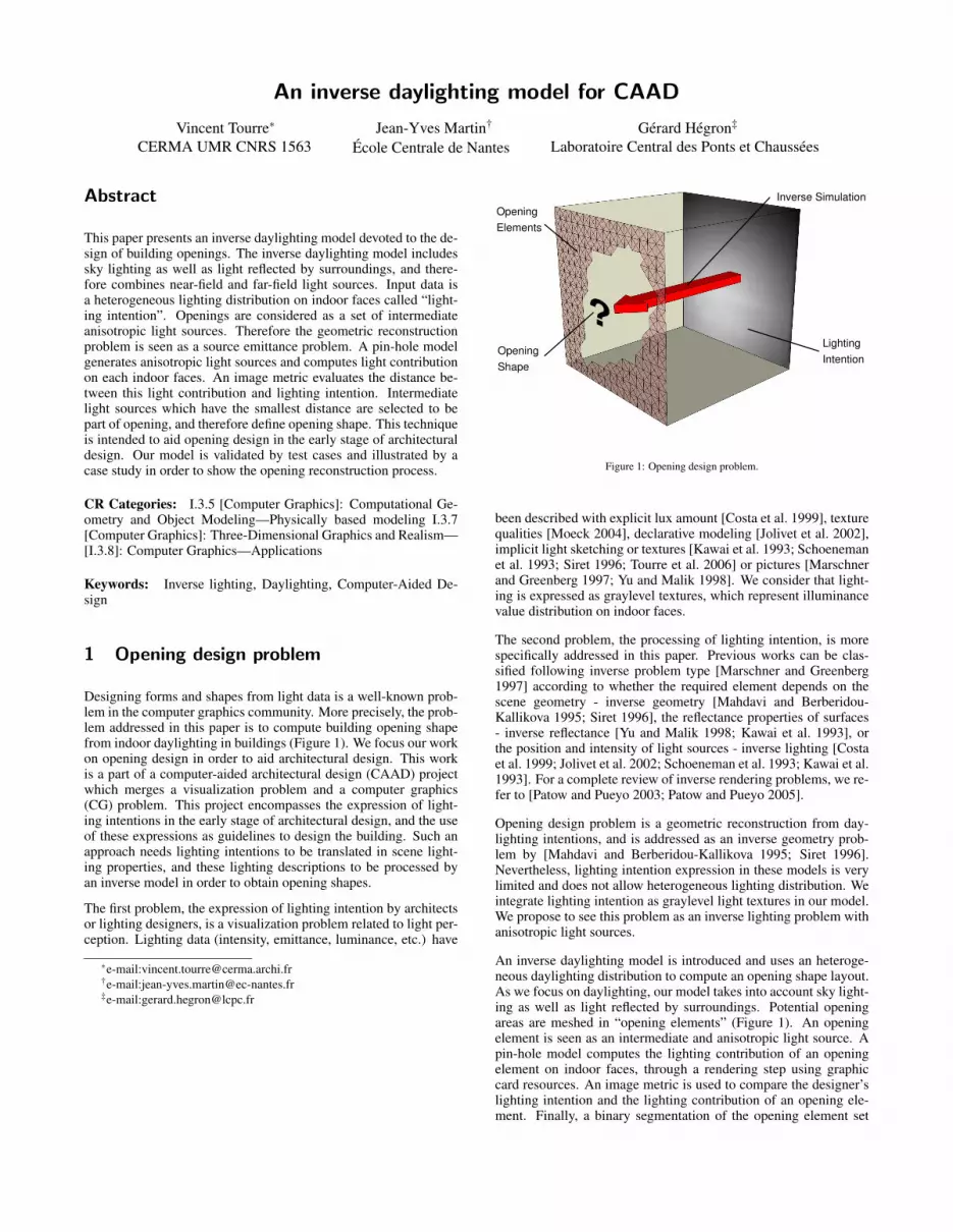
Designing forms and shapes from light data is a well-known prob-lem in the computer graphics community. More precisely, the prob-lem addressed in this paper is to compute building opening shapefrom indoor daylighting in buildings (Figure 1). We focus our workon opening design in order to aid architectural design. This workis a part of a computer-aided architectural design (CAAD) projectwhich merges a visualization problem and a computer graphics(CG) problem. This project encompasses the expression of light-ing intentions in the early stage of architectural design, and the useof these expressions as guidelines to design the building. Such anapproach needs lighting intentions to be translated in scene light-ing properties, and these lighting descriptions to be processed byan inverse model in order to obtain opening shapes.
The first problem, the expression of lighting intention by architectsor lighting designers, is a visualization problem related to light per-ception. Lighting data (intensity, emittance, luminance, etc.) have
∗e-mail:[email protected]†e-mail:[email protected]‡e-mail:[email protected]
Figure 1: Opening design problem.
been described with explicit lux amount [Costa et al. 1999], texturequalities [Moeck 2004], declarative modeling [Jolivet et al. 2002],implicit light sketching or textures [Kawai et al. 1993; Schoenemanet al. 1993; Siret 1996; Tourre et al. 2006] or pictures [Marschnerand Greenberg 1997; Yu and Malik 1998]. We consider that light-ing is expressed as graylevel textures, which represent illuminancevalue distribution on indoor faces.
The second problem, the processing of lighting intention, is morespecifically addressed in this paper. Previous works can be clas-sified following inverse problem type [Marschner and Greenberg1997] according to whether the required element depends on thescene geometry - inverse geometry [Mahdavi and Berberidou-Kallikova 1995; Siret 1996], the reflectance properties of surfaces- inverse reflectance [Yu and Malik 1998; Kawai et al. 1993], orthe position and intensity of light sources - inverse lighting [Costaet al. 1999; Jolivet et al. 2002; Schoeneman et al. 1993; Kawai et al.1993]. For a complete review of inverse rendering problems, we re-fer to [Patow and Pueyo 2003; Patow and Pueyo 2005].
Opening design problem is a geometric reconstruction from day-lighting intentions, and is addressed as an inverse geometry prob-lem by [Mahdavi and Berberidou-Kallikova 1995; Siret 1996].Nevertheless, lighting intention expression in these models is verylimited and does not allow heterogeneous lighting distribution. Weintegrate lighting intention as graylevel light textures in our model.We propose to see this problem as an inverse lighting problem withanisotropic light sources.
An inverse daylighting model is introduced and uses an heteroge-neous daylighting distribution to compute an opening shape layout.As we focus on daylighting, our model takes into account sky light-ing as well as light reflected by surroundings. Potential openingareas are meshed in “opening elements” (Figure 1). An openingelement is seen as an intermediate and anisotropic light source. Apin-hole model computes the lighting contribution of an openingelement on indoor faces, through a rendering step using graphiccard resources. An image metric is used to compare the designer’slighting intention and the lighting contribution of an opening ele-ment. Finally, a binary segmentation of the opening element set

allows defining a raw opening shape. These shapes can be used byarchitects to design building opening.
In section 2, our approach is delineated to explain how we camefrom geometric reconstruction problem to anisotropic source emit-tance problem. Section 3 describes our inverse lighting modelbased on three steps: anisotropic source generation, lighting eval-uation and opening element selection. Validation of this model isshown in section 4. Sections 5 & 6 present some test cases and acase study, before to conclude in section 7.
2 An opening focused approach
Our goal is to compute raw opening shapes from heterogeneousdaylighting intentions. Daylighting is considered according to day-light factor formula with sun/sky component (SC), external re-flected component (ERC) and internal reflected component (IRC).(Figure 2).
Figure 2: Daylight components 1. SC 2. ERC 3. IRC.
Sky is an extended, heterogeneous and dynamic source [Mahdaviand Berberidou-Kallikova 1995; Siret 1996] which influences sur-rounding lighting, which in turn influences indoor lighting ambi-ence. As SC lighting and ERC lighting mainly depend on openingproperties, we add SC and ERC features to our inverse daylightingmodel in order to compute building openings. Internal interreflec-tions are put aside in this paper, nevertheless we keep in mind thatwe will have to integrate IRC in our model. As our model encom-passes skylight (SC) and reflections from the external built environ-ment (ERC), we deal with light coming from the outside into theindoor space.
The inverse lighting simulation computes opening shape from light-ing properties. This is an inverse geometry problem as we are look-ing for scene geometry. However this geometry defines also day-light source visibility, so this problem could be seen as an inverselighting problem, source positioning or emittance research. There-fore this problem is not clearly identified in the inverse renderingframework as an inverse geometry problem or an inverse lightingproblem.
In addressing this problem as an inverse geometry problem, we facea large solution space as opening can be of any size, shape and num-ber. Getting back to an inverse lighting problem, we have to choosebetween the source positioning problem and the emittance problem.In the source positioning problem, the source position also deter-mines source emittance. Here we face a double problem which isvery difficult to solve. If we address this problem like an emittanceproblem, we get back to one problem. This approach forces us to
fix source position, and therefore it becomes a manageable prob-lem. We propose in the next section a source emittance approachbased on pin-hole model and image distance measurement to com-pute raw opening solutions.
3 Inverse daylighting model
The opening face is meshed into n opening elements. Each openingelement brings its own lighting contribution coming from skylight(SC) and surrounding reflected light (ERC) (Figure 3). As this light-
Figure 3: Light from sky and environment used to compute lighting contribution of an
opening element.
ing contribution is different according to light direction, an openingelement is considered as an anisotropic light source. The SC+ERClighting on indoor faces of several opening elements can be com-puted as a linear combination of their lighting contributions.
Our method is divided in three steps:
• Generation of light coming through each opening element.
• Evaluation of each opening element according to its light con-tribution to indoor lighting.
• Selection of an opening element subset in order to create anopening shape which produces lighting close to lighting in-tention.
3.1 Opening element light generation
Lighting contribution of each opening element is computed witha pin-hole model in order to obtain lighting from skylight SC andsurrounding reflected light ERC (Figure 3).
Actually, lighting contribution of an opening element can be com-puted with any rendering technique. Radiosity techniques are notadapted to compute lighting through tiny opening elements. A ray-casting technique could be used too, but the adaption of ray-castingengine to fit our needs is much more important than our model im-plementation.
As a virtual camera is used, we compute lighting contributionthanks to GPU in an easy-to-implement way. Our model can beseen as a kind of hemi-cube [Cohen and Greenberg 1985] cen-tered on opening element which allows to compute light field, andadapted to convex volumes.
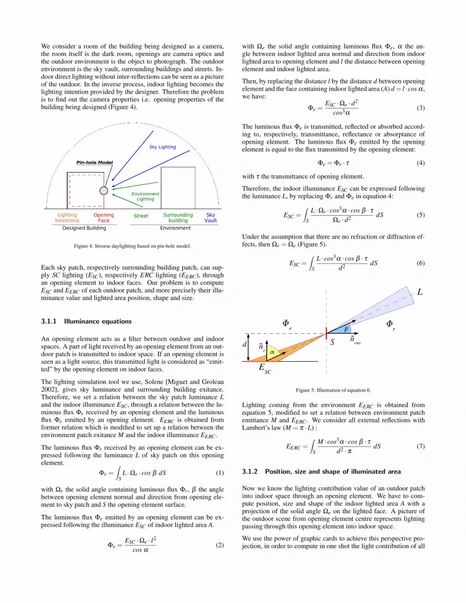
We consider a room of the building being designed as a camera,the room itself is the dark room, openings are camera optics andthe outdoor environment is the object to photograph. The outdoorenvironment is the sky vault, surrounding buildings and streets. In-door direct lighting without inter-reflections can be seen as a pictureof the outdoor. In the inverse process, indoor lighting becomes thelighting intention provided by the designer. Therefore the problemis to find out the camera properties i.e. opening properties of thebuilding being designed (Figure 4).
Figure 4: Inverse daylighting based on pin-hole model.
Each sky patch, respectively surrounding building patch, can sup-ply SC lighting (ESC), respectively ERC lighting (EERC), throughan opening element to indoor faces. Our problem is to computeESC and EERC of each outdoor patch, and more precisely their illu-minance value and lighted area position, shape and size.
3.1.1 Illuminance equations
An opening element acts as a filter between outdoor and indoorspaces. A part of light received by an opening element from an out-door patch is transmitted to indoor space. If an opening element isseen as a light source, this transmitted light is considered as “emit-ted” by the opening element on indoor faces.
The lighting simulation tool we use, Solene [Miguet and Groleau2002], gives sky luminance and surrounding building exitance.Therefore, we set a relation between the sky patch luminance Land the indoor illuminance ESC, through a relation between the lu-minous flux Φr received by an opening element and the luminousflux Φe emitted by an opening element. EERC is obtained fromformer relation which is modified to set up a relation between theenvironment patch exitance M and the indoor illuminance EERC.
The luminous flux Φr received by an opening element can be ex-pressed following the luminance L of sky patch on this openingelement.
Φr =∫
SL ·Ωr · cos β dS (1)
with Ωr the solid angle containing luminous flux Φr, β the anglebetween opening element normal and direction from opening ele-ment to sky patch and S the opening element surface.
The luminous flux Φe emitted by an opening element can be ex-pressed following the illuminance ESC of indoor lighted area A.
Φe =ESC ·Ωe · l
2
cos α(2)
with Ωe the solid angle containing luminous flux Φe, α the an-gle between indoor lighted area normal and direction from indoorlighted area to opening element and l the distance between openingelement and indoor lighted area.
Then, by replacing the distance l by the distance d between openingelement and the face containing indoor lighted area (A) d = l ·cos α ,we have:
Φe =ESC ·Ωe ·d
2
cos3α(3)
The luminous flux Φe is transmitted, reflected or absorbed accord-ing to, respectively, transmittance, reflectance or absorptance ofopening element. The luminous flux Φe emitted by the openingelement is equal to the flux transmitted by the opening element:
Φe = Φr · τ (4)
with τ the transmittance of opening element.
Therefore, the indoor illuminance ESC can be expressed followingthe luminance L, by replacing Φr and Φe in equation 4:
ESC =∫
S
L ·Ωr · cos3α · cos β · τ
Ωe ·d2dS (5)
Under the assumption that there are no refraction or diffraction ef-fects, then Ωr = Ωe (Figure 5).
ESC =∫
S
L · cos3α · cos β · τ
d2dS (6)
Figure 5: Illustration of equation 6.
Lighting coming from the environment EERC is obtained fromequation 5, modified to set a relation between environment patchemittance M and EERC. We consider all external reflections withLambert’s law (M = π ·L) :
EERC =∫
S
M · cos3α · cos β · τ
d2 ·πdS (7)
3.1.2 Position, size and shape of illuminated area
Now we know the lighting contribution value of an outdoor patchinto indoor space through an opening element. We have to com-pute position, size and shape of the indoor lighted area A with aprojection of the solid angle Ωe on the lighted face. A picture ofthe outdoor scene from opening element centre represents lightingpassing through this opening element into indoor space.
We use the power of graphic cards to achieve this perspective pro-jection, in order to compute in one shot the light contribution of all
outdoor patches through one opening element on one face. Withthis approach based on a perspective projection, we avoid a timeconsuming meshing of indoor faces to compute position, size andshape of illuminated area.
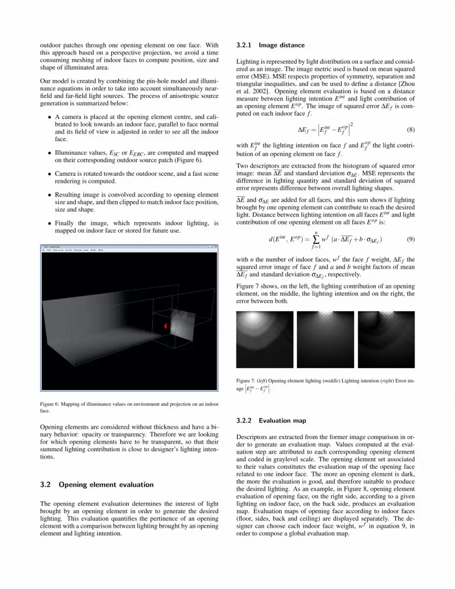
Our model is created by combining the pin-hole model and illumi-nance equations in order to take into account simultaneously near-field and far-field light sources. The process of anisotropic sourcegeneration is summarized below:
• A camera is placed at the opening element centre, and cali-brated to look towards an indoor face, parallel to face normaland its field of view is adjusted in order to see all the indoorface.
• Illuminance values, ESC or EERC, are computed and mappedon their corresponding outdoor source patch (Figure 6).
• Camera is rotated towards the outdoor scene, and a fast scenerendering is computed.
• Resulting image is convolved according to opening elementsize and shape, and then clipped to match indoor face position,size and shape.
• Finally the image, which represents indoor lighting, ismapped on indoor face or stored for future use.
Figure 6: Mapping of illuminance values on environment and projection on an indoor
face.
Opening elements are considered without thickness and have a bi-nary behavior: opacity or transparency. Therefore we are lookingfor which opening elements have to be transparent, so that theirsummed lighting contribution is close to designer’s lighting inten-tions.
3.2 Opening element evaluation
The opening element evaluation determines the interest of lightbrought by an opening element in order to generate the desiredlighting. This evaluation quantifies the pertinence of an openingelement with a comparison between lighting brought by an openingelement and lighting intention.
3.2.1 Image distance
Lighting is represented by light distribution on a surface and consid-ered as an image. The image metric used is based on mean squarederror (MSE). MSE respects properties of symmetry, separation andtriangular inequalities, and can be used to define a distance [Zhouet al. 2002]. Opening element evaluation is based on a distancemeasure between lighting intention E int and light contribution ofan opening element Eop. The image of squared error ∆E f is com-puted on each indoor face f .
∆E f =∣
∣
∣E intf −E
opf
∣
∣
∣
2(8)
with E intf the lighting intention on face f and E
opf the light contri-
bution of an opening element on face f .
Two descriptors are extracted from the histogram of squared errorimage: mean ∆E and standard deviation σ∆E . MSE represents thedifference in lighting quantity and standard deviation of squarederror represents difference between overall lighting shapes.
∆E and σ∆E are added for all faces, and this sum shows if lightingbrought by one opening element can contribute to reach the desiredlight. Distance between lighting intention on all faces E int and lightcontribution of one opening element on all faces Eop is:
d(E int, Eop) =
n
∑f=1
w f (a ·∆E f +b ·σ∆E f) (9)
with n the number of indoor faces, w f the face f weight, ∆E f thesquared error image of face f and a and b weight factors of mean∆E f and standard deviation σ∆E f
, respectively.
Figure 7 shows, on the left, the lighting contribution of an openingelement, on the middle, the lighting intention and on the right, theerror between both.
Figure 7: (left) Opening element lighting (middle) Lighting intention (right) Error im-
age
∣
∣
∣E int
f −Eopf
∣
∣
∣.
3.2.2 Evaluation map
Descriptors are extracted from the former image comparison in or-der to generate an evaluation map. Values computed at the eval-uation step are attributed to each corresponding opening elementand coded in graylevel scale. The opening element set associatedto their values constitutes the evaluation map of the opening facerelated to one indoor face. The more an opening element is dark,the more the evaluation is good, and therefore suitable to producethe desired lighting. As an example, in Figure 8, opening elementevaluation of opening face, on the right side, according to a givenlighting on indoor face, on the back side, produces an evaluationmap. Evaluation maps of opening face according to indoor faces(floor, sides, back and ceiling) are displayed separately. The de-signer can choose each indoor face weight, w f in equation 9, inorder to compose a global evaluation map.
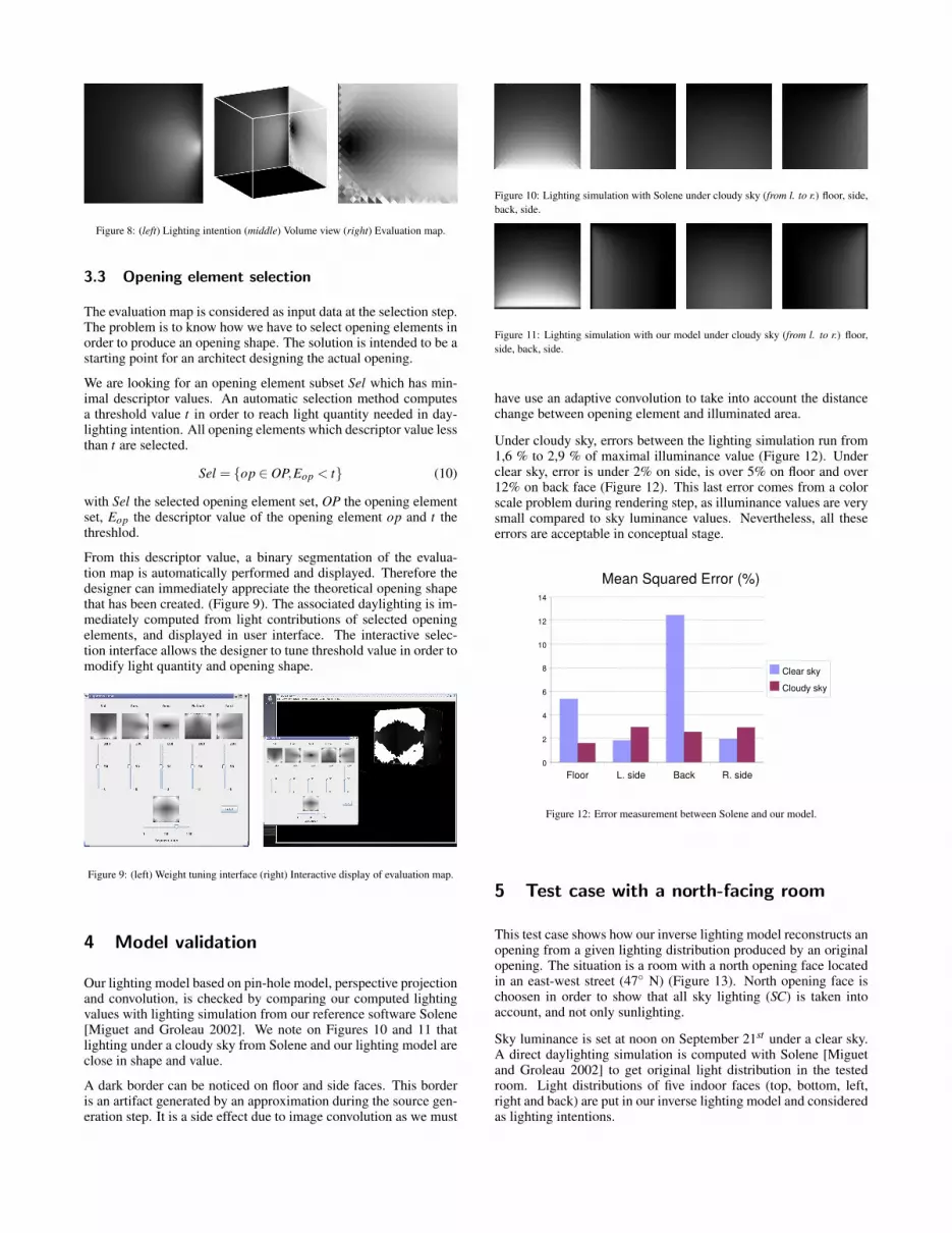
Figure 8: (left) Lighting intention (middle) Volume view (right) Evaluation map.
3.3 Opening element selection
The evaluation map is considered as input data at the selection step.The problem is to know how we have to select opening elements inorder to produce an opening shape. The solution is intended to be astarting point for an architect designing the actual opening.
We are looking for an opening element subset Sel which has min-imal descriptor values. An automatic selection method computesa threshold value t in order to reach light quantity needed in day-lighting intention. All opening elements which descriptor value lessthan t are selected.
Sel = op ∈ OP,Eop < t (10)
with Sel the selected opening element set, OP the opening elementset, Eop the descriptor value of the opening element op and t thethreshlod.
From this descriptor value, a binary segmentation of the evalua-tion map is automatically performed and displayed. Therefore thedesigner can immediately appreciate the theoretical opening shapethat has been created. (Figure 9). The associated daylighting is im-mediately computed from light contributions of selected openingelements, and displayed in user interface. The interactive selec-tion interface allows the designer to tune threshold value in order tomodify light quantity and opening shape.
Figure 9: (left) Weight tuning interface (right) Interactive display of evaluation map.
4 Model validation
Our lighting model based on pin-hole model, perspective projectionand convolution, is checked by comparing our computed lightingvalues with lighting simulation from our reference software Solene[Miguet and Groleau 2002]. We note on Figures 10 and 11 thatlighting under a cloudy sky from Solene and our lighting model areclose in shape and value.
A dark border can be noticed on floor and side faces. This borderis an artifact generated by an approximation during the source gen-eration step. It is a side effect due to image convolution as we must
Figure 10: Lighting simulation with Solene under cloudy sky (from l. to r.) floor, side,
back, side.
Figure 11: Lighting simulation with our model under cloudy sky (from l. to r.) floor,
side, back, side.
have use an adaptive convolution to take into account the distancechange between opening element and illuminated area.
Under cloudy sky, errors between the lighting simulation run from1,6 % to 2,9 % of maximal illuminance value (Figure 12). Underclear sky, error is under 2% on side, is over 5% on floor and over12% on back face (Figure 12). This last error comes from a colorscale problem during rendering step, as illuminance values are verysmall compared to sky luminance values. Nevertheless, all theseerrors are acceptable in conceptual stage.
Figure 12: Error measurement between Solene and our model.
5 Test case with a north-facing room
This test case shows how our inverse lighting model reconstructs anopening from a given lighting distribution produced by an originalopening. The situation is a room with a north opening face locatedin an east-west street (47 N) (Figure 13). North opening face ischoosen in order to show that all sky lighting (SC) is taken intoaccount, and not only sunlighting.
Sky luminance is set at noon on September 21st under a clear sky.A direct daylighting simulation is computed with Solene [Miguetand Groleau 2002] to get original light distribution in the testedroom. Light distributions of five indoor faces (top, bottom, left,right and back) are put in our inverse lighting model and consideredas lighting intentions.

Figure 13: (left) North-facing room and street (right) Axonometric view.
Mean square value descriptor and standard deviation descriptor areequally weighted on the evaluation maps (b in Figures 16 & 17).Interactive selection method is used with values between 25% to40% of maximum descriptor value.
The test case process is summarized in Figure 14. Original openingshape is compared with the evaluation map and the reconstructedopening shape obtained at the selection step. The designer can pro-pose several interpretations of the reconstructed opening shape. Aforward lighting simulation is then computed with the interpretedopening shape in order to compare the result with the original lightdistribution.
Figure 14: Test case process.
When only the sky is considered as a light source (SC lighting), theceiling receives no direct light at all and therefore only the floor andthree walls are considered. We show opening reconstruction resultsfor horizontal opening with SC lighting, and cross-shape openingwith SC and SC+ERC lightings (c in Figures 15, 16 & 17).
The horizontal opening reconstruction with the SC lighting is notso far from the original horizontal opening and therefore producesa lighting which matches initial intentions (Figure 15).
Figure 15: (a) Horizontal original opening (b) Opening evaluation map (c) Opening
reconstruction with SC.
The cross-shaped opening reconstruction with the SC lightingmisses the top part of the cross (Figure 16). Since the sky is theonly light source, the ceiling is not lighted. The inverse lightingprocess depends on other faces and highest opening elements bringa very diffuse light to these faces. Therefore the top part of cross isnot necessary to reproduce lighting given as an intention.
Figure 16: (a) Cross-shaped original opening (b) Opening evaluation map (c) Opening
reconstruction with SC.
The cross-shaped opening reconstruction with the SC+ERC light-ing gets the higher part of the cross. the ERC lighting brings usefullighting data specifically on ceiling and allows retrieving a crossshape (Figure 17). Nevertheless we note this map is less accuratethan the previous one because the SC+ERC lighting is more diffusethan the SC lighting on all indoor faces.
Figure 17: (a) Cross-shaped original opening (b) Opening evaluation map (c) Opening
reconstruction with SC+ERC.
The last opening reconstruction is interpreted from an architecturalpoint of view as a diamond-shaped opening. A light simulation iscomputed with Solene [Miguet and Groleau 2002] in order to com-pare original illuminance values from cross-shaped opening andthose from diamond-shaped opening (Figure 18).
These results are computed with our prototype implemented inJAVA on Intel Core 2 Duo computer with 2 Gb RAM and QuadroFX 550 graphic card. J3D, Swing and Java Advanced Imaging li-braries are used to manage respectively 3D, user interface and im-age comparison.
The test scene contains an opening face with 1024 patches, 5 indoorfaces and an environment (sky and street) with more than 10,000patches. Execution times are approximatively 1 hour for generation

Figure 18: Illuminance values on a side wall from Solene (left) Cross-shaped opening
(right) Diamond-shaped opening.
step, with one third for image input/output, 20 minutes for evalua-tion step and few seconds for selection step. Memory used duringexecution is about 500 Mb, with 300 Mb dedicated to projectionimages from generation step.
6 Case study
We asked an architect to express some lighting intentions in a sim-ple volume as a sketch (Figure 19). This sketch was scanned,clipped and projected in order to get indoor face lighting as textures.These textures were integrated in our model with design interface(Figure 20). Our inverse model computed an evaluation map, andthe architect interpreted it to design his own opening. Lighting pro-duced by this final opening was confronted to original intention.
Light source generation was computed under clear sky with SC andERC lighting at noon on September 21st . Source evaluations wereperformed with standard deviation σ∆E . Evaluation maps relatedto each indoor face were computed and displayed in selection inter-face (Figure 21). The designer can tune indoor face weight to adjusthis intention through vertical cursors under each indoor face. Theglobal evaluation map is immediately computed following indoorface weights, and displayed.
Sources are selected thanks to segmentation cursor (Figure 22). Asthe cursor moves, opening shape is drawn by opening element se-lection, and the room is interactively relighted. Segmentation cur-sor minimum and maximum are respectively the best and the worstevaluation values. Therefore, this cursor can be seen as a tolerancevalue: the more the designer gives a high value with this cursor, themore he has to accept to be far from his original intention.
This theoretical solution was translated into opening shape by anthe architect in three ways according to his sensibility. A lightingsimulation with Solene was computed from the first interpretationin order to compare illuminance values with original lighting inten-tions (Figure 23). As we can see on these figures, lighting producedby the first opening interpretation brings more light in the bottomright corner, although it does not match exactly the original lightingintention. Nevertheless, the idea behind this intention “one cornerin shadow and one corner in light” is respected.
7 Conclusion and Further works
Our main contribution is an inverse lighting model which takes intoaccount daylighting with sun/sky and external reflected components(SC+ERC). We show that an inverse geometry problem for open-ing design, can be seen as an inverse lighting problem. Our inverse
Figure 19: Original intention drawing.
Figure 20: Lighting intentions in our model.
Figure 21: Evaluation maps displayed in user interface.

Figure 22: Opening element selection and interactive segmentation.
Figure 23: Lighting simulation with Solene of the first architectural interpretation.
lighting model integrates anisotropic light sources, and is able toreconstruct openings from heterogeneous lighting distribution in asimple room. A model implementation has been tested by an archi-tect who used it to draw some sketches. Therefore results producedby this inverse lighting model can be an aid to architectural designfor sketching opening.
Where further works are concerned, we look for integration of in-terreflections, lighting color and several times of the day. We alsoneed to demonstrate that our model scales to realistic scenes andis able to handle several openings in order to be useful for archi-tects. The integration of this method in a CAAD tool will allow thedesigner to experiment computer-aided “design by ambience inten-tion” in order to explore his own architectural solutions from thetheoretical ones proposed by our inverse daylighting model.
References
COHEN, M. F., AND GREENBERG, D. P. 1985. The hemi-cube: a radiosity solution for complex environments. In SIG-GRAPH ’85: Proceedings of the 12th annual conference on
Computer graphics and interactive techniques, ACM, NewYork,NY, USA, 31–40.
COSTA, A. C., SOUSA, A. A., AND FERREIRA, F. N. 1999. Opti-misation and lighting design. In WSCG’99 Proceedings, 29–36.
JOLIVET, V., PLEMENOS, D., AND POULINGEAS, P. 2002. In-verse direct lighting with a monte carlo method and declarativemodeling. In International Conference on Computational Sci-ence (2), 3–12.
KAWAI, J. K., PAINTER, J. S., AND COHEN, M. F. 1993. Radiop-timization: goal based rendering. In SIGGRAPH ’93: Proceed-ings of the 20th annual conference on Computer graphics andinteractive techniques, ACM, New York, NY, USA, 147–154.
MAHDAVI, A., AND BERBERIDOU-KALLIKOVA, L. 1995. A gen-erative simulation tool for architectural lighting. In 4th Inter-national Conference of the International Building PerformanceSimulation Association (IBPSA), J. Mitchell and W. A. Beck-man, Eds., 395–402.
MARSCHNER, S. R., AND GREENBERG, D. P. 1997. Inverse light-ing for photography. In Proceedings of the Fifth Color ImagingConference, Society for Imaging Science and Technology, 262–265.
MIGUET, F., AND GROLEAU, D. 2002. A daylight simulation toolfor urban and architectural spaces : Application to transmitteddirect and diffuse light through glazing. Building and Environ-ment 37, 8-9, 833–843.
MOECK, M. 2004. Constraint satisfaction software for architec-tural lighting design: A case study. Leukos 1, 1, 101–127.
PATOW, G., AND PUEYO, X. 2003. A survey of inverse renderingproblems. Computer Graphics Forum 22, 4, 663–687.
PATOW, G., AND PUEYO, X. 2005. A survey of inverse surfacedesign from light transport behaviour specification. ComputerGraphics Forum 24, 4, 773–789.
SCHOENEMAN, C., DORSEY, J., SMITH, B., ARVO, J., AND
GRENNBERG, D. 1993. Painting with light. In Proceedingsof the 20th annual ACM Conference on Computer graphics andinteractive Techniques (SIGGRAPH), ACM Press, 143–146.
SIRET, D. 1996. A generative computer tool to model shadings andopenings that achieve sunlighting properties in architectural de-sign. In Development and application of Computer techniquesto environmental studies VI (Proceedings of ENVIROsoft’96),Computational mechanics Publications, 695–704.
TOURRE, V., MARTIN, J.-Y., AND HEGRON, G. 2006. Archi-tectural lighting ambience intentions for inverse rendering. In3IA’06 : Computer graphics and artificial intelligence, D. Ple-menos, Ed., 211–218.
YU, Y., AND MALIK, J. 1998. Recovering photometric propertiesof architectural scenes from photographs. In SIGGRAPH ’98:Proceedings of the 25th annual conference on Computer graph-ics and interactive techniques, ACM, New York, NY, USA, 207–217.
ZHOU, H., CHEN, M., AND WEBSTER, M. F. 2002. Comparativeevaluation of visualization and experimental results using imagecomparison metrics. In VIS ’02: Proceedings of the conferenceon Visualization ’02, IEEE Computer Society, Washington, DC,USA, 315–322.