design and evaluation of hydraulic lime grouts for the strengthening of stone masonry historic...
TRANSCRIPT
ORIGINAL ARTICLE
Design and evaluation of hydraulic lime groutsfor the strengthening of stone masonry historic structures
A. Kalagri • A. Miltiadou-Fezans • E. Vintzileou
Received: 5 August 2008 / Accepted: 7 December 2009
� RILEM 2010
Abstract The present paper discusses an experi-
mental procedure realized in order to design hydrau-
lic lime based grouts adequate for the strengthening
of stone masonry historic structures. With the aim to
minimize incompatibility problems between the
original materials and the grouts, several natural
hydraulic lime based grouts, as well as a ternary
(lime–pozzolan–cement) grout with reduced cement
content, have been studied. The selection of the most
suitable grouts was performed based on a set of
criteria, namely injectability, mechanical and dura-
bility characteristics. The selected grouts were sub-
sequently injected into cylindrical specimens that
simulate the infill of three-leaf stone masonry. The
experimental results obtained from mechanical tests
carried out on the injected cylinders demonstrated
that all grout mixes studied within this work were
efficient in strengthening the infill material; they
exhibited, however, differences in terms of durability
properties. Finally, an empirical formula was
developed to predict the compressive strength of the
injected infill, as a function of the mechanical
properties of grouts.
Resume Dans cet article on presente une methode
experimentale appliquee dans le but d’etudier des
coulis a base de chaux hydraulique qui seraient
adequats pour le renforcement de constructions his-
toriques en maconnerie en pierre. On a etudie
plusieurs types de coulis (coulis a base de chaux
hydraulique ainsi que coulis ternaires [chaux-pouzzo-
lane-ciment] a pourcentage reduit de ciment) dans le
but de minimiser les problemes d’incompatibilite entre
les coulis et les materiaux originaux. La selection des
coulis les plus adequats a ete effectuee sur la base d’un
groupe de criteres concernant l’injectabilite, ainsi que
des proprietes mecaniques et de durabilite. Les coulis
choisis ont ete ensuite injectes dans des eprouvettes
cylindriques qui simulent le remplissage d’une ma-
connerie historique. Les resultats experimentaux obt-
enus sur les eprouvettes cylindriques ont montre
l’efficacite du point de vue mecanique de tous les
coulis choisis. Il a cependant ete constate qu’il y a des
differences en ce qui concerne leur durabilite. Final-
ement, il a ete developpe une relation empirique qui
permet de calculer la resistance du remplissage en
compression apres l’injection, en fonction des propri-
etes mecaniques du coulis.
Keywords Hydraulic lime � Grout �Three-leaf masonry � Infill material �
A. Kalagri � A. Miltiadou-Fezans (&)
Hellenic Ministry of Culture, Directorate for Technical
Research on Restoration, 6-8 Tzireon Str., 10186 Athens,
Greece
e-mail: [email protected]
E. Vintzileou
National Technical University of Athens, Department
of Structural Engineering, Laboratory of Reinforced
Concrete, 5 Iroon Polytechniou Str., 15773 Zografou,
Greece
Materials and Structures
DOI 10.1617/s11527-009-9572-1
Injectability � Mechanical characteristics �Durability
1 Introduction
Grouting constitutes one of the most common
techniques applied for the repair and strengthening
of masonry structures or fissured architectural mem-
bers, when interconnected voids in adequate percent-
age are present. It has the advantage of retrieving the
continuity, cohesion and strength of the damaged
structures without altering their morphology and
load-bearing system. Given that grouting is an
irreversible intervention, the design of the grout as
well as the method of its application to historic
structures must satisfy a series of performance
requirements, comprising that of re-treatability. The
performance requirements involve injectability,
strength and durability aspects and they are set on
the basis of an overall approach of the structure to be
repaired, before and after intervention (i.e. the
construction type and the dimensions of the structure,
the nature of the existing materials, the nominal
minimum width of voids to be filled and the
distribution of voids, the eventual existence of
soluble salts, the desired behaviour after repair, etc).
Among the above requirements, the injectability
capacity of the grout constitutes a key parameter for a
successful intervention. Specific criteria for the design
of grouts, which link the estimated nominal minimum
width of voids to be filled (Wnom) with basic properties
of the grout composition, have been proposed in the
literature [1–3]. Based on these criteria and using
commercial materials, one can prepare hydraulic
grouts injectable in voids and cracks of a nominal
minimum width of 0.1–0.2 mm. For lower nominal
minimum widths, that correspond to very fine silt or
clay, the penetrability of hydraulic grouts cannot be
satisfactory. That is why when an important percent-
age of clay and silt is present as loose material, a
successful injection cannot be assured.
Due to the great variety of masonry types and
materials, and in order to better take into account the
aforementioned difficulties of hydraulic grouts to
penetrate in extremely fine voids, the importance of
evaluating the injectability capacity of the grout for
each specific case before intervention (by injecting
plexiglas cylinders containing samples of the real
materials taken from the internal leaf of the masonry
to be repaired), was recognized and a methodology
was suggested for site and laboratory investigation
[4–7].
Further research on the subject led to a proposal of
new rational criteria for the holistic design of
hydraulic grouts, [8], as well as to the development
of modern practical guidelines for the application of
injections and the in situ quality control of the whole
intervention, including detailed records of the grout
consumption per masonry volume [9, 10].
In this framework, a comparative study was
undertaken for the design of grouts using a series of
commercial hydraulic limes. In fact, although hydrau-
lic lime-based grouts (hydraulic lime with or without a
pozzolanic material) seem to offer a promising
alternative to the ternary grouts (with limited cement
content) due to their similarity with the in situ
materials and their mechanical efficiency for the
structural restoration of stone masonry, only few
studies have been devoted to them so far [6, 11, 12].
The present research aims to contribute to the
documentation of hydraulic lime based grouts; it
examines some of the most important parameters that
influence their performance, namely the injectability
and durability characteristics and the mechanical
properties of the examined compositions. The study
is completed with mechanical tests on large scale (2/3)
specimens that simulate the infill material of three-leaf
stone masonry, strengthened by the selected grouts. It
should be noted that this investigation was carried out
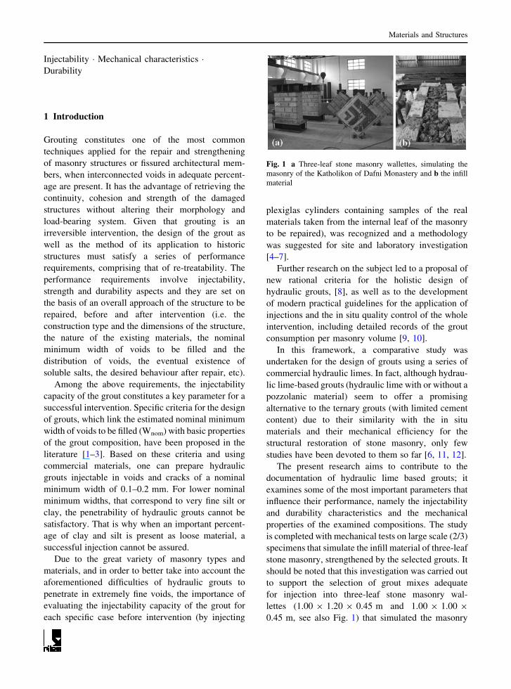
to support the selection of grout mixes adequate
for injection into three-leaf stone masonry wal-
lettes (1.00 9 1.20 9 0.45 m and 1.00 9 1.00 9
0.45 m, see also Fig. 1) that simulated the masonry
Fig. 1 a Three-leaf stone masonry wallettes, simulating the
masonry of the Katholikon of Dafni Monastery and b the infill
material
Materials and Structures
of the Katholikon of Dafni Monastery, one of the most
important monuments of middle Byzantine period in
Greece, inscribed in the world heritage list of UNE-
SCO. The results of the entire experimental program
on wallettes are published elsewhere [13].
2 Materials
Four natural hydraulic limes (A: NHL5 of St. Astier,
B: Chaux Blanche NHL 3.5Z of Lafarge, C: Calx
Romana of IAR and D: Albaria Calce Albazzana of
Degussa), as well as a premixed grouting material
with binder based on natural hydraulic lime (Unilit B
Fluid 0/0 of Unilit), have been examined. According
to the laser grain size analysis, the diameter corre-
sponding to i) the 85% passing and ii) the 99%
passing of the solid phase of the grouts fulfilled the
penetrability grading criteria for voids and cracks of
nominal minimum width Wnom * 200 lm (i.e. d85 \(Wnom/5) = 40 lm and d99 \ (Wnom/2) = 100 lm,
respectively) [2].
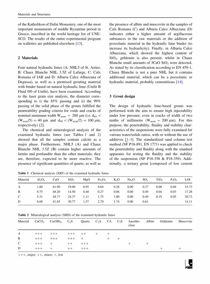
The chemical and mineralogical analysis of the
examined hydraulic limes (see Tables 1 and 2)
showed that all the samples contain calcite as a
major phase. Furthermore, NHL5 (A) and Chaux
Blanche NHL 3.5Z (B) contain higher amounts of
larnite and portlandite than the other materials; they
are, therefore, expected to be more reactive. The
presence of significant quantities of quartz, as well as
the presence of albite and muscovite in the samples of
Calx Romana (C) and Albaria Calce Albazzana (D)
indicates either a higher amount of argillaceous
substances in the raw materials or the addition of
pozzolanic material in the hydraulic lime binder (to
increase its hydraulicity). Finally, in Albaria Calce
Albazzana, which showed the highest content of
SiO2, gehlenite is also present, whilst in Chaux
Blanche small amounts of 3CaO SiO2 were detected.
As stated by its classification according to EN 459-1,
Chaux Blanche is not a pure NHL but it contains
additional material, which can be a pozzolanic or
hydraulic material, probably cementitious [14].
3 Grout design
The design of hydraulic lime-based grouts was
performed with the aim to ensure high injectability
under low pressure, even in cracks of width of two
tenths of millimetre (Wnom * 200 lm). For this
purpose, the penetrability, fluidity and stability char-
acteristics of the suspensions were fully examined for
various water/solids ratios, with or without the use of
additives [1–3]. The standardized sand column test
method (NF P18-891, EN 1771) was applied to check
the penetrability and fluidity along with the standard
apparatus for testing the fluidity and the stability
of the suspension (NF P18-358 & P18-359). Addi-
tionally, a ternary grout [composed of low cement
Table 1 Chemical analysis (XRF) of the examined hydraulic limes
Material Al2O3 CaO SiO2 MgO Fe2O3 K2O Na2O SO3 TiO2 P2O5 LOI
A 1.80 61.90 19.00 0.95 0.64 0.28 0.00 0.37 0.08 0.04 15.73
B 0.75 68.20 14.50 0.40 0.27 0.06 0.00 0.49 0.04 0.03 17.28
C 5.31 44.77 24.37 1.11 1.75 1.00 0.00 0.49 0.19 0.05 20.73
D 6.68 41.65 30.77 1.57 2.70 1.74 0.00 0.61 14.11
Table 2 Mineralogical analysis (XRD) of the examined hydraulic limes
Material CaCO3 Ca(OH)2 C2S Quartz C3A CA C3S Anortho-
clase
Albite Gehlenite Muscovite
A ??? ??? ??? ?? ? ?
B ??? ??? ??? ? ? ?
C ??? ? ?? ??? ? ?
D ??? ? ?? ??? ? ?
???, major; ??, minor; ?, low
Materials and Structures
percentage (30%, Danish white cement), lime (25%),
pozzolan (45%) and superplasticizer (1%)] was
examined. An ultrasound dispersion mixer, assisted
by a mechanical device of low turbulence, was used
throughout the program. The mixing time was 3 min
for the hydraulic lime-based grouts and 6 min for the
ternary grout (2 min/solid component).
The following limit values were set for the
acceptance of grouts: A time limit of 50 s for the
sand column penetrability test (T36); an efflux time
(td=4.7 mm) of 500 ml of grout less than 45 s (fluidity
test using a Marsh cone with a nozzle-diameter
d = 4.7 mm) and fluidity factor higher than
0.7 9 103 mm/s (based on measurements with a
Marsh cone with 3 mm nozzle-diameter), [3]; max-
imum acceptable limit of 5% was set for the bleeding
test [1]. In order to reach similar injectability
characteristics for all grout mixes with the lowest
possible water content, the use of an adequate
superplasticizer was necessary for some of the grout
compositions. The selection of the type and percent-
age of superplasticizer was performed on the basis of
a preliminary study for each grout solid phase
composition. As presented in Table 3 for the grouts
G1, G2 and G4 three different types of superplast-
icizer were used respectively: SP1, SP2 and SP3,
based on naphthalenesulfonate polymer (Rheobuild
5000 of Basf), lignonaphthalene salts (CHEM SPL M
of Domylco) and polycarboxylic ether (Glenium 51
of Basf).
The evaluation of the grouts capacity was per-
formed on the basis of their injectability (fluidity,
penetrability, stability), their resistance to salt decay
and their mechanical characteristics (flexural and
compressive strength). Tables 3, 4 and 5 summarize
the main test results.
For the evaluation of the mechanical properties of
grouts, specimens of 40 9 40 9 160 mm were used.
The curing conditions were kept constant at 90 ± 5%
RH and 20�C (EN 459/2) until the execution of the
tests at the ages of 28, 90 and 180 days. Because of
the lack of specialized standards for the mechanical
testing of grouts, the procedure adopted here was
based mainly on standard NBN EN 1015-11 (1999)
and similar researches reported in the literature
[1, 11, 15–17].
In general, the compressive strength (measured
on 40 9 40 9 40 mm specimens) of the selected
grouts increased with time (grouts G1, G2, G3 and
G4) or remained approximately constant (grouts G5,
G6 and G7) after the age of 90 days. On the
contrary, their flexural strength (measured by three-
point bending test on 40 9 40 9 160 mm speci-
mens) showed a decrease with time for grouts G5,
G6 and G7, after the age of 90 days. This reduction
of flexural strength can be attributed to the micro-
cracking [16, 17] caused by the significant carbon-
ation observed (by applying phenolphthalein) in
specimens of grouts G5, G6 and G7, between the
age of 90 and 180 days. This microcracking is
attributed to the difference between the regions of
grout that are close to the surfaces of the specimen
and, hence, carbonated, and those away from edges
that are still hydrating. Hydration causes chemical
shrinkage and induces tensile stresses (and thus
microcracking) at the interface of a carbonated (and
thus inert) part of the material and a non carbonated
(and thus hydrating) part of it [16, 17]. Nevertheless,
this reduction of flexural strength in some of the
grouts was not taken as a criterion for rejecting the
respective mixes, as significant carbonation is not
expected to occur within the mass of masonry under
consideration.
On the basis of their compressive (fgc) strength (at
6 months), the selected grouts (Table 3) can be clas-
sified in three categories: (a) ternary grout (W/S =
0.8), having fgc = 10.6 MPa and fgt = 3.1 MPa, (b)
hydraulic lime-based grouts (W/S = 0.8), having fgc
of 6–6.7 MPa and fgt of 1.0–3.9 MPa and (c) hydraulic
lime-based grouts (W/S = 0.7), having fgc of 2.5–
2.9 MPa and fgt of 0.6–1.1 MPa.
Sodium sulphate salt durability tests were carried
out (following a procedure described in [18] for
stone specimens, slightly adapted, since grouts
cannot be subjected to a drying procedure at
105�C). At ambient temperature (20�C), grout
specimens (cubes 20 9 20 9 20 mm) cured up to
the age of 9 months under 90 ± 5% RH and 20�C,
are impregnated with mirabilite (Na2SO4�10H2O)
saturated solutions and dried for six cycles at 20�C.
After the sixth cycle, half of the specimens were
dried at 20�C and the others at 50�C until constant
mass was reached. Table 4 summarizes the results
of the salt decay tests. The figures included illustrate
the indicative damage patterns observed for each
grout formulation.
Materials and Structures
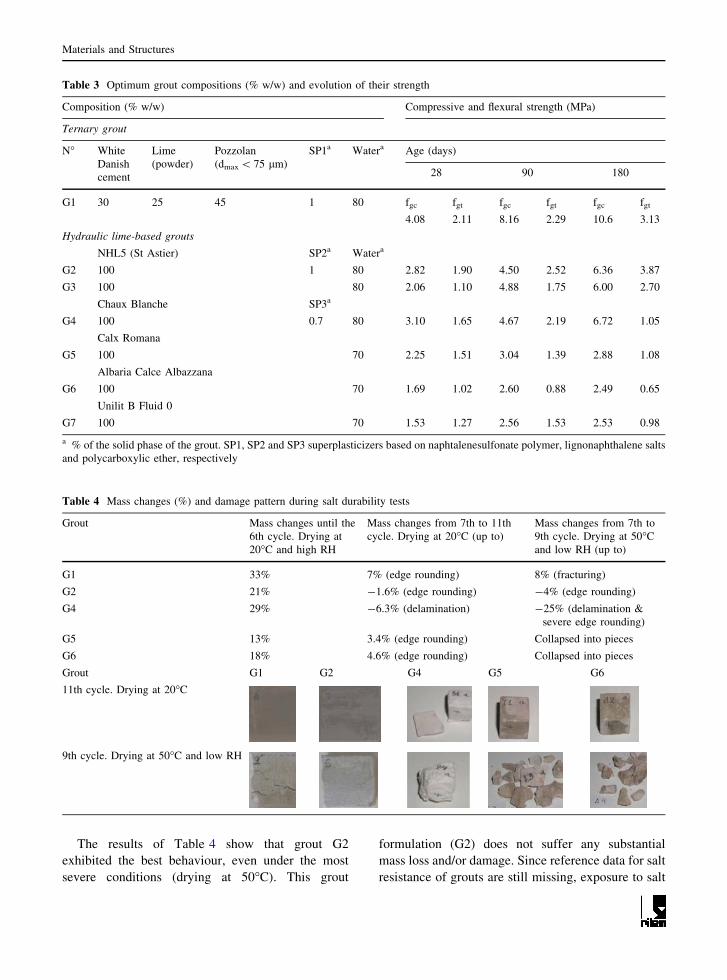
The results of Table 4 show that grout G2
exhibited the best behaviour, even under the most
severe conditions (drying at 50�C). This grout
formulation (G2) does not suffer any substantial
mass loss and/or damage. Since reference data for salt
resistance of grouts are still missing, exposure to salt
Table 3 Optimum grout compositions (% w/w) and evolution of their strength
Composition (% w/w) Compressive and flexural strength (MPa)
Ternary grout
N� White
Danish
cement
Lime
(powder)
Pozzolan
(dmax \ 75 lm)
SP1a Watera Age (days)
28 90 180
G1 30 25 45 1 80 fgc fgt fgc fgt fgc fgt
4.08 2.11 8.16 2.29 10.6 3.13
Hydraulic lime-based grouts
NHL5 (St Astier) SP2a Watera
G2 100 1 80 2.82 1.90 4.50 2.52 6.36 3.87
G3 100 80 2.06 1.10 4.88 1.75 6.00 2.70
Chaux Blanche SP3a
G4 100 0.7 80 3.10 1.65 4.67 2.19 6.72 1.05
Calx Romana
G5 100 70 2.25 1.51 3.04 1.39 2.88 1.08
Albaria Calce Albazzana
G6 100 70 1.69 1.02 2.60 0.88 2.49 0.65
Unilit B Fluid 0
G7 100 70 1.53 1.27 2.56 1.53 2.53 0.98
a % of the solid phase of the grout. SP1, SP2 and SP3 superplasticizers based on naphtalenesulfonate polymer, lignonaphthalene salts
and polycarboxylic ether, respectively
Table 4 Mass changes (%) and damage pattern during salt durability tests
Grout Mass changes until the
6th cycle. Drying at
20�C and high RH
Mass changes from 7th to 11th
cycle. Drying at 20�C (up to)
Mass changes from 7th to
9th cycle. Drying at 50�C
and low RH (up to)
G1 33% 7% (edge rounding) 8% (fracturing)
G2 21% -1.6% (edge rounding) -4% (edge rounding)
G4 29% -6.3% (delamination) -25% (delamination &
severe edge rounding)
G5 13% 3.4% (edge rounding) Collapsed into pieces
G6 18% 4.6% (edge rounding) Collapsed into pieces
Grout G1 G2 G4 G5 G6
11th cycle. Drying at 20�C
9th cycle. Drying at 50�C and low RH
Materials and Structures
influences should be carefully investigated before
intervention (in the laboratory and even in situ when
possible).
After characterization was completed, all these
grout formulations (G1–G7) of similar injectability
characteristics (see Table 5), were injected at low
pressure (0.75 bar) into cylindrical specimens that
were constructed in purpose in the laboratory to
simulate the infill material of the three-leaf stone
masonry under consideration. The main objective of
this investigation was the comparison of the selected
grouts regarding their capacity to improve the
mechanical characteristics of the infill material.
4 Mechanical properties of filling material before
and after grouting
To produce specimens simulating in a reproducible
way the intermediate leaf (filling material) of three-
leaf masonry, plastic cylindrical moulds (diameter
D = 250 mm, height H = 500 mm) were filled with
a mix of predetermined amounts of lime/pozzolan
mortar and pieces of travertine stone, in order to
reach a percentage of voids of approximately 40% of
the total volume of the cylinder, which is a typical
percentage for the infill material of deteriorated
historic three-leaf masonry [1, 11]. The entire proce-
dure for the preparation of specimens was similar to
that described elsewhere [1, 15]. Thus, for each
specimen 22.5 kg of stones (size: 20–50 mm) and
10.5 kg of mortar were mixed manually and then the
mixture was disposed by hand without compaction in
the mould, in a way to keep the distribution of empty
spaces dispersed in a relatively uniform way. Both at
the bottom and top of the mould a 2 cm-thick layer of
mortar was bedded. The dimensions of cylindrical
specimens were selected with the purpose to repro-
duce (almost in natural scale) the filling material of
the three-leaf stone masonry of the specific
monument. Scale effects (e.g. by carrying out tests
on cylinders according to ASTM Standard C943)
were not considered, as it was assumed that the
results of this research are realistic (being conducted
practically under natural scale) and conservative
enough as testing on smaller cylinders would result
to higher mechanical properties.
Although initially it was planned to test the
cylinders before grouting (to their maximum resis-
tance), only three (out of twenty-eight) cylinders
were tested in compression before grouting (Table 6).
The testing program was modified for the following
reasons: (a) the examined infill is composed by pieces
of stone with a low content of mortar, and hence a
high percentage of voids (including large voids, but
also very fine ones especially in the mortar and in the
interfaces between mortar and stones); thus, large
axial deformations and excessive lateral dilatancy of
the cylinders were observed, as already reported in
the literature [15], and the moulds could not be re-
used for the procedure of grouting and (b) due to the
texture of the ungrouted cylinders, vertical strains
could not be measured in a reliable way, since
measuring devices could not be fixed on the cylinders
(Fig. 2a). On the basis of the results obtained from
testing three ungrouted cylinders, a mean compres-
sive strength of 0.15 N/mm2 was measured for the
ungrouted filling material.
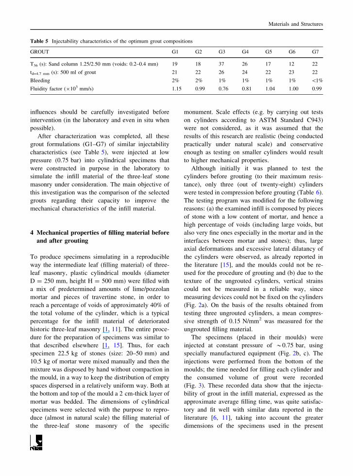
The specimens (placed in their moulds) were
injected at constant pressure of *0.75 bar, using
specially manufactured equipment (Fig. 2b, c). The
injections were performed from the bottom of the
moulds; the time needed for filling each cylinder and
the consumed volume of grout were recorded
(Fig. 3). These recorded data show that the injecta-
bility of grout in the infill material, expressed as the
approximate average filling time, was quite satisfac-
tory and fit well with similar data reported in the
literature [6, 11], taking into account the greater
dimensions of the specimens used in the present
Table 5 Injectability characteristics of the optimum grout compositions
GROUT G1 G2 G3 G4 G5 G6 G7
T36 (s): Sand column 1.25/2.50 mm (voids: 0.2–0.4 mm) 19 18 37 26 17 12 22
td=4.7 mm (s): 500 ml of grout 21 22 26 24 22 23 22
Bleeding 2% 2% 1% 1% 1% 1% \1%
Fluidity factor (9103 mm/s) 1.15 0.99 0.76 0.81 1.04 1.00 0.99
Materials and Structures
work. The average grout volume consumed per
cylinder vary from 7.3 to 9.1 lt; this means that
35.5–42.2%, of the total volume was filled with grout
(see Table 6).This is a very satisfactory result, as the
total porosity of the specimens was of the order of
40%. Apart of the filling of large voids between
pieces of stones, an important part of the very fine
voids of the mortar itself were also filled improving
the cohesion of the mixed material and the adherence
at the interfaces, as already reported in the literature
[15]. Evidently, the very fine voids, having a width
lower than the nominal minimum one taken into
account for the design of the grouts were not filled.
After 180 days of curing (under 90 ± 5% RH, 20�C),
the grouted cylinders were tested in compression.
Table 6 summarizes the results of testing of the
grouted cylinders, whereas typical stress–strain
curves are given in Fig. 4. The failure mode of
cylinders was characterized by the formation of
almost vertical cracks, typical for cohesive/adhesive
failure (Fig. 5).
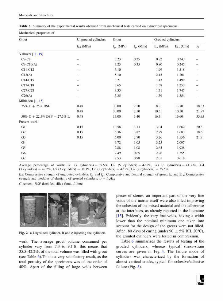
Table 6 Summary of the experimental results obtained from mechanical tests carried on cylindrical specimens
Mechanical properties of
Grout Ungrouted cylinders Grout Grouted cylinders
fi,0 (MPa) fgc (MPa) fgt (MPa) fi,s (MPa) Ei,s (GPa) kf
Valluzzi [11, 19]
C7-C8 – 3.23 0.35 0.82 0.343 –
C9-C10(A) – 3.23 0.35 0.80 0.245 –
C11-C12 – 5.10 1.99 1.518 –
C13(A) – 5.10 2.15 1.201 –
C14-C15 – 3.21 1.43 1.499 –
C17-C18 – 3.65 1.38 1.253 –
C27-C28 – 3.35 1.71 1.747 –
C26(A) – 3.35 1.39 1.354 –
Miltiadou [1, 15]
75% C ? 25% DSF 0.48 30.00 2.50 8.8 13.70 18.33
0.48 30.00 2.50 10.5 10.50 21.87
50% C ? 22.5% DSF ? 27.5% L 0.48 13.00 1.40 16.3 16.60 33.95
Present work
G1 0.15 10.58 3.13 3.04 1.662 20.3
G2 0.15 6.36 3.87 2.79 1.683 18.6
G3 0.15 6.00 2.70 3.26 1.556 21.7
G4 6.72 1.05 3.25 2.097
G5 2.88 1.08 2.65 1.928
G6 2.49 0.65 2.26 1.355
G7 2.53 0.98 2.01 0.618
Average percentage of voids: G1 (7 cylinders) = 39.5%, G2 (5 cylinders) = 42.2%, G3 (6 cylinders) = 41.30%, G4
(3 cylinders) = 42.2%, G5 (3 cylinders) = 38.1%, G6 (2 cylinders) = 42.2%, G7 (2 cylinders) = 35.5%
fi,0: Compressive strength of ungrouted cylinders; fgc and fgt: Compressive and flexural strength of grout; fi,s and Ei,s: Compressive
strength and modulus of elasticity of grouted cylinders; kf = fi,s/fi,0
C cement, DSF densified silica fume, L lime
Fig. 2 a Ungrouted cylinder, b and c injecting the cylinders
Materials and Structures

Although the compressive strength of the grouts
varies between 2.5 and 10.5 MPa, allowing for a
rough classification of the grouts into three categories
as mentioned in Sect. 3, the measured compressive
strength of the grouted cylinders varies only between
2.0 and 3.3 MPa. This indicates that the compressive
strength of the grout is not the decisive property for
its mechanical efficiency in the strengthening of the
infill material, as already reported in the literature
[1, 20–22].
One may observe (Fig. 6) that, in general, the
strain corresponding to the compressive strength of
grouted cylinders is smaller for higher compressive
strength of the injected grout. As shown in Fig. 6,
although the scatter of the measured strain values is
rather high, there is a tendency of stronger grouts to
produce a stiffer grouted filling material.
This is confirmed by the data of Fig. 7, where the
secant modulus of elasticity of grouted cylinders (at a
compressive stress equal to 1/3 of the compressive
strength) is plotted against the compressive strength
of the injected grout, as well as by the data of Fig. 8,
where the ratio between the strain at max strength and
the respective compressive strength of grouted cyl-
inders is plotted against the compressive strength of
the cylinders.
The moduli of elasticity vary from 0.6 to 2 GPa,
showing good agreement with published data for such
type of grouts [11]. It should be noted that the
measured differences in moduli of elasticity are not in
direct relationship with the compressive strength of
the grout: for a compressive strength of grout varying
165
135160
142131
0
50
100
150
200
Ave
rage
fill
ing
tim
e (s
ec)
G1 G2 G3 G4 G5
(a)
(b)
8.39.1 8.8 9
8.19
7.3
0
2
4
6
8
10
Ave
rage
gro
ut v
olum
e co
nsum
ed p
er c
ylin
der
(lt)
G1 G2 G3 G4 G5 G6 G7
Fig. 3 a Time needed for filling of the cylinders, b Average
grout volume consumed per cylinder
0
0.5
1
1.5
2
2.5
3
3.5
-0.01 -0.008 -0.006 -0.004 -0.002 0 0.002
(M
Pa)
N5SP-1 N5SP-2
N5SP-3 N5SP-4P
Fig. 4 Typical stress–strain curves (cylinders injected with
grout G2)
Fig. 5 Typical failure mode of injected cylinders
0 2 4 6 8 10 12
COMPRESSIVE STRENGTH OF GROUT (MPa)
0
0.002
0.004
0.006
0.008
0.01
STR
AIN
AT
ST
RE
NG
TH
(‰
)
Fig. 6 Relationship between the strain at strength and the
compressive strength of the grout
Materials and Structures
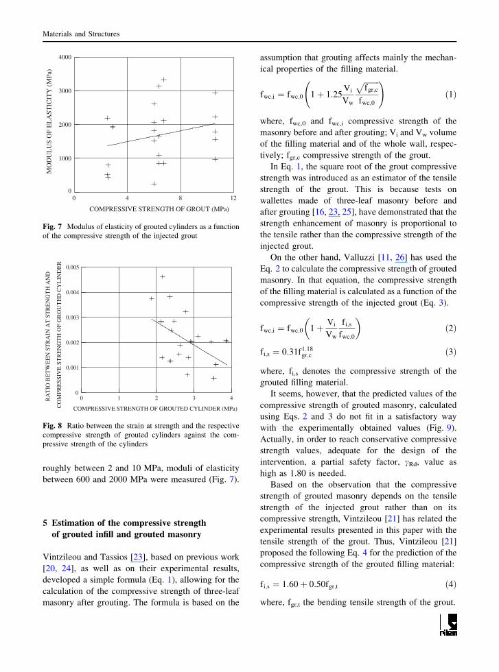
roughly between 2 and 10 MPa, moduli of elasticity
between 600 and 2000 MPa were measured (Fig. 7).
5 Estimation of the compressive strength
of grouted infill and grouted masonry
Vintzileou and Tassios [23], based on previous work
[20, 24], as well as on their experimental results,
developed a simple formula (Eq. 1), allowing for the
calculation of the compressive strength of three-leaf
masonry after grouting. The formula is based on the
assumption that grouting affects mainly the mechan-
ical properties of the filling material.
fwc;i ¼ fwc;0 1þ 1:25Vi
Vw
ffiffiffiffiffiffiffiffi
fgr;c
p
fwc;0
!
ð1Þ
where, fwc,0 and fwc,i compressive strength of the
masonry before and after grouting; Vi and Vw volume
of the filling material and of the whole wall, respec-
tively; fgr,c compressive strength of the grout.
In Eq. 1, the square root of the grout compressive
strength was introduced as an estimator of the tensile
strength of the grout. This is because tests on
wallettes made of three-leaf masonry before and
after grouting [16, 23, 25], have demonstrated that the
strength enhancement of masonry is proportional to
the tensile rather than the compressive strength of the
injected grout.
On the other hand, Valluzzi [11, 26] has used the
Eq. 2 to calculate the compressive strength of grouted
masonry. In that equation, the compressive strength
of the filling material is calculated as a function of the
compressive strength of the injected grout (Eq. 3).
fwc;i ¼ fwc;0 1þ Vi
Vw
fi;s
fwc;0
� �
ð2Þ
fi;s ¼ 0:31f1:18gr;c ð3Þ
where, fi,s denotes the compressive strength of the
grouted filling material.
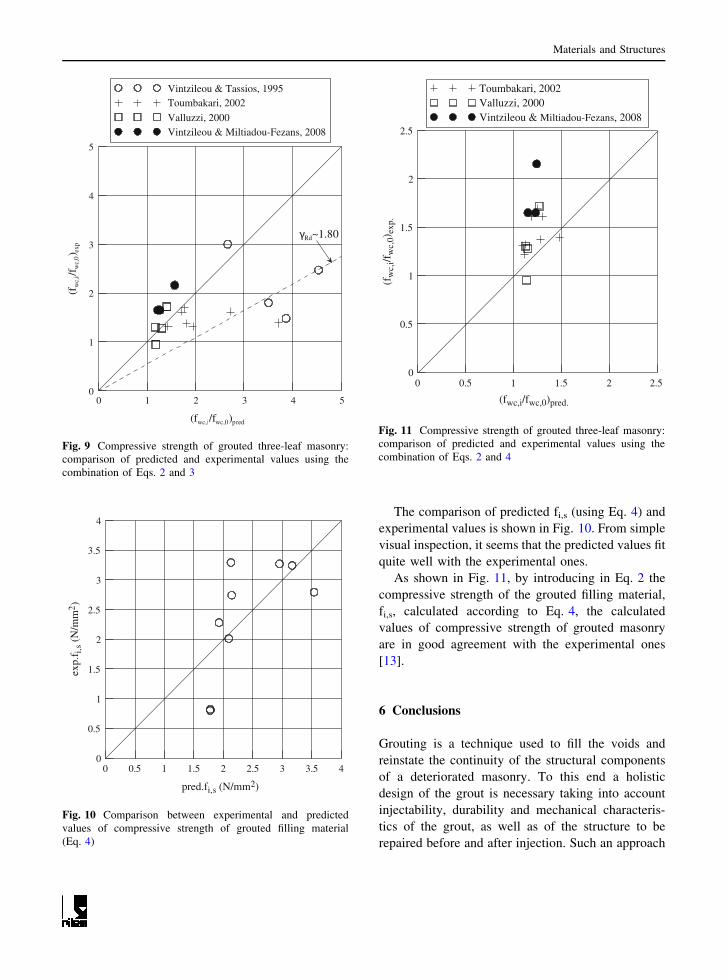
It seems, however, that the predicted values of the
compressive strength of grouted masonry, calculated
using Eqs. 2 and 3 do not fit in a satisfactory way
with the experimentally obtained values (Fig. 9).
Actually, in order to reach conservative compressive
strength values, adequate for the design of the
intervention, a partial safety factor, cRd, value as
high as 1.80 is needed.
Based on the observation that the compressive
strength of grouted masonry depends on the tensile
strength of the injected grout rather than on its
compressive strength, Vintzileou [21] has related the
experimental results presented in this paper with the
tensile strength of the grout. Thus, Vintzileou [21]
proposed the following Eq. 4 for the prediction of the
compressive strength of the grouted filling material:
fi;s ¼ 1:60þ 0:50fgr;t ð4Þ
where, fgr,t the bending tensile strength of the grout.
0 4 8 12
COMPRESSIVE STRENGTH OF GROUT (MPa)
0
1000
2000
3000
4000M
OD
UL
US
OF
EL
AST
ICIT
Y (
MPa
)
Fig. 7 Modulus of elasticity of grouted cylinders as a function
of the compressive strength of the injected grout
0 1 2 3 4
COMPRESSIVE STRENGTH OF GROUTED CYLINDER (MPa)
0
0.001
0.002
0.003
0.004
0.005
RA
TIO
BE
TW
EE
N S
TR
AIN
AT
ST
RE
NG
TH
AN
D
CO
MPR
ESS
IVE
ST
RE
NG
TH
OF
GR
OU
TE
D C
YL
IND
ER
Fig. 8 Ratio between the strain at strength and the respective
compressive strength of grouted cylinders against the com-
pressive strength of the cylinders
Materials and Structures
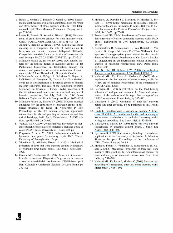
The comparison of predicted fi,s (using Eq. 4) and
experimental values is shown in Fig. 10. From simple
visual inspection, it seems that the predicted values fit
quite well with the experimental ones.
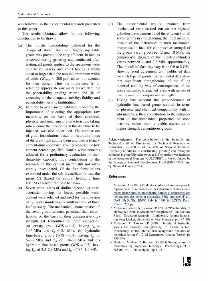
As shown in Fig. 11, by introducing in Eq. 2 the
compressive strength of the grouted filling material,
fi,s, calculated according to Eq. 4, the calculated
values of compressive strength of grouted masonry
are in good agreement with the experimental ones
[13].
6 Conclusions
Grouting is a technique used to fill the voids and
reinstate the continuity of the structural components
of a deteriorated masonry. To this end a holistic
design of the grout is necessary taking into account
injectability, durability and mechanical characteris-
tics of the grout, as well as of the structure to be
repaired before and after injection. Such an approach
0 1 2 3 4 5
(fwc,i/fwc,0)pred
0
1
2
3
4
5
(fw
c,i/f
wc,
0) e
xp
Vintzileou & Tassios, 1995Toumbakari, 2002
Valluzzi, 2000Vintzileou & Miltiadou-Fezans, 2008
γRd~1.80
Fig. 9 Compressive strength of grouted three-leaf masonry:
comparison of predicted and experimental values using the
combination of Eqs. 2 and 3
0 0.5 1 1.5 2 2.5 3 3.5 4
pred.fi,s (N/mm2)
0
0.5
1
1.5
2
2.5
3
3.5
4
exp.
f i,s
(N/m
m2 )
Fig. 10 Comparison between experimental and predicted
values of compressive strength of grouted filling material
(Eq. 4)
0 0.5 1 1.5 2 2.5
(fwc,i/fwc,0)pred.
0
0.5
1
1.5
2
2.5
(fw
c,i/f
wc,
0)ex
p.
Toumbakari, 2002Valluzzi, 2000Vintzileou & Miltiadou-Fezans, 2008
Fig. 11 Compressive strength of grouted three-leaf masonry:
comparison of predicted and experimental values using the
combination of Eqs. 2 and 4
Materials and Structures
was followed in the experimental research presented
in this paper.
The results obtained allow for the following
conclusions to be drawn:
(a) The holistic methodology followed for the
design of stable, fluid and highly injectable
grouts was proven to be very efficient. In fact, as
observed during grouting and confirmed after
testing, all grouts applied to the specimens were
able to fill cracks and voids having a width
equal or larger than the nominal minimum width
of voids (Wnom * 200 lm) taken into account
for their design. Thus the importance (i) of
selecting appropriate raw materials which fulfill
the penetrability grading criteria and (ii) of
executing all the adequate stability, fluidity and
penetrability tests is highlighted.
(b) In order to avoid incompatibility problems, the
importance of selecting the appropriate raw
materials, on the basis of their chemical,
physical and mechanical characteristics, taking
into account the properties of the structure to be
injected, was also underlined. The comparison
of grout formulations based on hydraulic limes
of different type among them and with a ternary
cement–lime–pozzolan grout (composed of low
cement percentage, 30% Danish white cement)
allowed for a preliminary evaluation of their
durability capacity, thus contributing to the
research on this critical matter still not suffi-
ciently investigated. Of the five formulations
examined under the salt crystallization test, the
grout G2 (based on natural hydraulic lime
NHL5) exhibited the best behavior.
(c) Seven grout mixes of similar injectability char-
acteristics having the lowest possible water
content were selected and used for the injection
of cylinders simulating the infill material of three
leaf masonry. The mechanical characteristics of
the seven grouts selected permitted their classi-
fication on the basis of their compressive (fgc)
strength (at 6 months) in three categories:
(a) ternary grout (W/S = 0.8), having fgc =
10.6 MPa and fgt = 3.1 MPa, (b) hydraulic
lime-based grouts (W/S = 0.8), having fgc of
6–6.7 MPa and fgt of 1.0–3.9 MPa and (c)
hydraulic lime-based grouts (W/S = 0.7), hav-
ing fgc of 2.5–2.9 MPa and fgt of 0.6–1.1 MPa.
(d) The experimental results obtained from
mechanical tests carried out on the injected
cylinders have demonstrated the efficiency of all
seven grouts in strengthening the infill material,
despite of the differences in their mechanical
properties. In fact, for compressive strength of
the grouts varying between 2 and 10 MPa, the
compressive strength of the injected cylinders
varies between 2 and 3.3 MPa approximately.
The moduli of elasticity vary from 0.6 to 2 GPa,
showing good agreement with published data
for such type of grouts. Experimental data show
that significant strengthening of the filling
material and, by way of consequence, of the
entire masonry, is reached even with grouts of
low to medium compressive strength.
(e) Taking into account the preponderance of
hydraulic lime based grouts studied, in terms
of physical and chemical compatibility with in
situ materials, their contribution to the enhance-
ment of the mechanical properties of stone
masonry makes them a viable alternative to
higher strength cementitious grouts.
Acknowledgment The contribution of the Scientific and
Technical staff of Directorate for Technical Research on
Restoration, as well as of the staff of National Technical
University of Athens, in constructing, grouting and testing the
cylinders is gratefully acknowledged. The project was included
in the Operational Program ‘‘CULTURE’’. It was co-funded by
the European Regional Development Fund (ERDF-75%) and
by National Funds (25%).
References
1. Miltiadou AE (1991) Etude des coulis hydrauliques pour la
reparation et le renforcement des structures et des monu-
ments historiques en maconnerie. Etudes et recherches des
laboratoires des ponts et chaussees, Serie ouvrages d’ art,
OA8 (Ph.D. Th., ENPC Pub. in 1991 by LCPC), Paris,
France, 278 pp
2. Miltiadou-Fezans A, Tassios TP (2003) ‘‘Penetrability of
Hydraulic Grouts in Structural Strengthening’’. In: Barsony
J (ed) ‘‘Structural research’’, Anniversary volume honour-
ing Peter Lenkei. University of Pecs, Hungary, pp 197–209
3. Miltiadou A, Tassios TP (2007) Fluidity of hydraulic
grouts for masonry—strengthening. In: Gorun A (ed)
Proceedings of the international symposium ‘‘studies on
historical heritage’’, 17–21 September, Antalya, Turkey, pp
339–346
4. Binda L, Modena C, Baronio G (1993) Strengthening of
masonries by injection technique. Proceedings of 6
NAMC, vol I, Philadelphia, pp 1–14
Materials and Structures
5. Binda L, Modena C, Baronio G, Gelmi A (1994) Experi-
mental qualification of injection admixtures used for repair
and strengthening of stone masonry walls. In: 10th Inter-
national Brick/Block Masonry Conference, Calgary, vol 2,
pp 539–548
6. Laefer D, Baronio G, Anzani A, Binda L (1998) Measure-
ment of grout injection efficacy for stone masonry walls.
Conv. 7 NAMC, Notre Dame, USA, vol 1, pp 484–496
7. Anzani A, Baronio G, Binda L (1998) Multiple leaf stone
masonry as a composite: the role of materials on its
behaviour and repair. Incomarech-Raphael 97/E/412,
Compatible materials for the protection of european cul-
tural heritage, PACT 55, ISSN: 0257-8727, pp 177–212
8. Miltiadou-Fezans A, Tassios TP (2006) New rational cri-
teria for the holistic design of hydraulic grouts. In: 1st
Panhellenic Conference on Restoration, Society for
research and promotion of scientific restoration of monu-
ments, 14–17 June Thessaloniki, Greece (in Greek)
9. Miltiadou-Fezans A, Kalagri A, Kakkinou S, Ziagou A,
Delinikolas N, Zarogianni E, Chorafa E (2008) Method-
ology for in situ application of hydraulic grouts on historic
masonry structures. The case of the Katholikon of Dafni
Monastery. In: D’Ayala D, Fodde E (eds) Proceedings of
the 6th international conference on structural analysis of
historic construction, 2–4 July, Bath, UK, CRC Press/
Balkema, Taylor and Francis Group, vol II, pp 1025–1033
10. Miltiadou-Fezans A, Tassios TP (2009) Modern practical
guidelines for the application of hydraulic grouts in his-
torical structures. In: Dousi M, Nikiforithis P (eds)
Proceedings of the 3rd national congress appropriate
interventions for the safeguarding of monuments and his-
torical buildings, 9–11 April, Thessaloniki, IAMOR edi-
tions, pp 485–494 (in Greek)
11. Valluzzi M-R (2000) Comportamento meccanico di mur-
ature storiche consolidate con materiali e tecniche a base di
calce. Ph.D. Thesis, University of Trieste, 276 pp
12. Pingarron Alvarez V (2006) Performance analysis of
hydraulic lime grouts for masonry repair, Ph.D. Thesis,
University of Pennsylvania, 164 pp
13. Vintzileou E, Miltiadou-Fezans A (2008) Mechanical
properties of three-leaf stone masonry grouted with ternary
or hydraulic lime based grouts. Eng Struct 30(8):2265–
2276
14. Gaetani MC, Santamaria U (1998) I Materiali di Restauro:
le malte da inezione. Diagnosi et Progetto per la conserv-
azione dei materiali dell’ Architettura. ICR/Ministero per i
Beni Culturali e Ambientali. Edizioni De Luca, Roma, pp
357–375
15. Miltiadou A, Durville J-L, Martineau F, Massieu E, Ser-
rano J-J (1993) Etude mecanique de melanges cailloux-
mortier-influence de l’injection de coulis. Bulletin de liai-
son, Laboratoire des Ponts et Chaussees-183- janv.- fevr.
1993, Ref. 3677, pp 75–84
16. Toumbakari EE (2002) Lime-Pozzolan-Cement grouts and
their structural effects on composite masonry walls. Ph.D.
Thesis, Department of Civil Engineering, KULeuven,
364 pp
17. Keersmaekers R, Schueremans L, Van Rickstal F, Van
Gemert D, Knapen M, Posen D (2006) NDT-control of
injection of an appropriate grout mixture for the consoli-
dation of the columns foundations of Our Lady’s Basilica
at Tongeren (B). In: 5th international seminar on structural
analysis of historical constructions. New Delhi, India,
pp 553–560
18. Tsui N, Flatt RJ, Scherer GW (2003) Crystallization
damage by sodium sulphate. J Cult Herit 4:109–115
19. Valluzzi MR, Da Porto F, Modena C (2003) Grout
requirements for the injection of stone masonry walls. In:
A new era of building. Proceedings of the conference of
ICPCM, Cairo, Egypt
20. Egermann R (1993) Investigation on the load bearing
behavior of multiple leaf masonry. In: Structural preser-
vation of the architectural heritage. Proceedings of the
IABSE symposium, Rome, Italy, pp 305–312
21. Vintzileou E (2010) Mechanics of three-leaf masonry
before and after grouting. To be published in Int J Archit
Herit
22. Binda L, Pina-Henriques J, Anzani A, Fontana A, Lour-
enco PB (2006) A contribution for the understanding of
load-transfer mechanisms in multi-leaf masonry walls:
testing and modelling. Eng Struct 28(8):1132–1148
23. Vintzileou E, Tassios TP (1995) Three leaf stone masonry
strengthened by injecting cement grouts. J Struct Eng
ASCE 121(5):848–856
24. Egermann R (1993) Stone masonry buildings: research and
applications at the University of Karlsruhe. In Murature
Sicurezza Recupero. Proceedings of the conference of
ITEA, Trento, Italy, pp 70–95
25. Miltiadou-Fezans A, Vintzileou E, Papadopoulou E, Kal-
agri A (2006) Mechanical properties of three-leaf stone
masonry after grouting. In: 5th international seminar on
structural analysis of historical constructions. New Delhi,
India, pp 791–798
26. Valluzzi MR, Da Porto F, Modena C (2004) Behavior and
modelling of strengthened three-leaf stone masonry walls.
Mater Struct 37:184–192
Materials and Structures