definition of prime mover
TRANSCRIPT
1
Lecture note on Module 1, Mining Machinery,5th Semester Mining Engineering
Definition of Prime Mover
The actual meaning of prime mover is a primary source of power. It means all the machinery that provide power for performing different mechanical work. Technically, it is a group of machines that transform energy from thermal, electrical or pressure into mechanical form for use in different sources for some mechanical work. Engines and turbines are examples.
Types of prime movers
The prime movers are listed based on the sources of energy utilized by them.
A. Thermal prime movers
These are the prime movers which use the thermal energy of source to produce power. Different thermal prime movers are given below: - Fuels (Heat engines): - These prime movers use several fuels like petrol, diesel, oil, gas to produce mechanical power. Heat engines are two types: -
1. External combustion engines: -Reciprocating steam engines Steam turbine Closed cycle gas turbine
2. Internal combustion engines: -Reciprocating I.C. engines Open cycle gas turbine
Nuclear (Nuclear power plant): - This prime mover utilises the heat energy of atoms by fission or fusion method to develop the mechanical power. It is chiefly used in nuclear power plants. Different radioactive components like uranium, thorium is used for these fission or fusion process in a nuclear reactor.
Geothermal: - In this kind of prime mover the heat energy is recovered from a certain depth or the hot part of the earth beneath earth surface then it is transformed into mechanical by the proper engine.
Biogas: - Biogas is principally produced from garbage or any other waste which is used to generate power by the prime mover in a biogas plant.
Solar energy: - The solar energy spread to the earth in the form of radiation or electromagnetic waves. This energy trapped in with the help of solar panel made up of semiconductor element. This heat energy is then turned into power.
2
B. Non-thermal prime movers: - These kinds of prime movers do not use the heat energy to transform it into mechanical power. The following are the non-thermal prime movers: -
Hydraulic turbines: - This kind of prime mover uses the stored potential energy of water to generate power.
Wind power: - With the help of the wind turbine, wind energy is transformed into power.
Tidal power: - The energy of tides from the ocean is transformed into power by the use of the turbine which is known as tidal power.
INTERNAL COMBUSTION ENGINES(I C ENGINE)
An Engine is a device which transforms the chemical energy of a fuel into thermal energy and uses this thermal energy to produce mechanical work. Engines normally convert thermal energy into mechanical work and therefore they are called heat engines. Heat engines can be broadly classified into: i) External combustion engines (E C Engines) ii) Internal combustion engines (I C Engines )
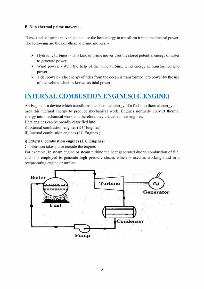
i) External combustion engines (E C Engines) Combustion takes place outside the engine. For example, In steam engine or steam turbine the heat generated due to combustion of fuel and it is employed to generate high pressure steam, which is used as working fluid in a reciprocating engine or turbine.

3
ii) Internal combustion engines (I C Engines)
Internal combustion engines can be classified as Continuous IC engines and Intermittent IC engines.
In continuous IC engines products of combustion of the fuel enters into the prime mover as the working fluid. For example: In Open cycle gas turbine plant. Products of combustion from the combustion chamber enters through the turbine to generate the power continuously. See Figure 2. In this case, same working fluid cannot be used again in the cycle. In Intermittent internal combustion engine combustion of fuel takes place inside the engine cylinder. Power is generated intermittently (only during power stroke) and flywheel is used to provide uniform output torque. Usually these engines are reciprocating engines. The reciprocating engine mechanism consists of piston which moves in a cylinder and forms a movable gas tight seal. By means of a connecting rod and a crank shaft arrangement, the reciprocating motion of piston is converted into a rotary motion of the crankshaft. They are most popular because of their use as main prime mover in commercial vehicles. ADVANTAGES OF INTERNAL COMBUSTION ENGINES Greater mechanical simplicity. Higher power output per unit weight because of absence of auxiliary units like boiler,
condenser and feed pump Low initial cost Higher brake thermal efficiency as only a small fraction of heat energy of the fuel is
dissipated to cooling system These units are compact and requires less space Easy starting from cold conditions
DISADVANTAGES OF INTERNAL COMBUSTION ENGINES I C engines cannot use solid fuels which are cheaper. Only liquid or gaseous fuel of
given specification can be efficiently used. These fuels are relatively more expensive. I C engines have reciprocating parts and hence balancing of them is problem and they
are also susceptible to mechanical vibrations.

4
CLASSIFICATION OF INTERNAL COMBUSTION ENGINES. There are different types of IC engines that can be classified on the following basis. 1. According to thermodynamic cycle i) Otto cycle engine or Constant volume heat supplied cycle. ii) Diesel cycle engine or Constant pressure heat supplied cycle iii) Dual-combustion cycle engine 2. According to the fuel used: i) Petrol engine ii) Diesel engine iii) Gas engine 3. According to the cycle of operation: i) Two stroke cycle engine ii) Four stroke cycle engine 4. According to the method of ignition: i) Spark ignition (S.I) engine ii) Compression ignition (C I ) engine 5. According to the number of cylinders. i) Single cylinder engine ii) Multi cylinder engine 6. According to the arrangement of cylinder: i) Horizontal engine ii) Vertical engine iii) V-engine v) In-line engine vi) Radial engine, etc. 7. According to the method of cooling the cylinder: i) Air cooled engine ii) Water cooled engine 8. According to their applications: i) Stationary engine ii) Automobile engine iii) Aero engine iv) Locomotive engine v) Marine engine, etc. INTERNAL COMBUSTION ENGINE PARTS AND THEIR FUNCTION 1. Cylinder: - It is a container fitted with piston, where the fuel is burnt and power is produced. 2.Cylinder Head/Cylinder Cover: - One end of the cylinder is closed by means of cylinder head. This consists of inlet valve for admitting air fuel mixture and exhaust valve for removing the products of combustion. 3. Piston: - Piston is used to reciprocate inside the cylinder. It transmits the energy to crankshaft through connecting rod. 4. Piston Rings: - These are used to maintain a pressure tight seal between the piston and cylinder walls and also it transfers the heat from the piston head to cylinder walls. 5. Connecting Rod: - One end of the connecting rod is connected to piston through piston pin while the other is connected to crank through crank pin. It transmits the reciprocator motion of piston to rotary crank. 6. Crank: - It is a lever between connecting rod and crank shaft. 7. Crank Shaft: - The function of crank shaft is to transform reciprocating motion in to a rotary motion. 8. Fly wheel: - Fly wheel is a rotating mass used as an energy storing device.

5
9. Crank Case: - It supports and covers the cylinder and the crank shaft. It is used to store the lubricating oil.
Hydraulics Power
Hydraulics is used for the generation, control, and transmission of power using pressurized liquids.
It is a technology and applied science involving mechanical properties and use of liquids.
Hydraulic systems require a pump and, like pneumatic systems, uses valves to control the force and velocity of the actuators.
6
Industrial applications of hydraulics use 1 000 to 5 000 psi or more than 10 000 psi for specialized application.
The word hydraulics originates from Greek words hydro – water and aulos – pipe.
The equipment required for a hydraulic system: hydraulic fluid, cylinder, piston, pumps, and valves that control the direction of flow, which is always in one direction
Advantages of Hydraulics Hydraulic systems are more capable of moving heavier loads and providing higher
forces due to the incompressibility of liquids. Hydraulic systems do many purposes at one time, including lubrication, cooling, and
power transmission. Hydraulic powered machines operate at higher pressures (1 500 to 2 500 psi),
generating higher force from small-scale actuators. Hydraulic systems are larger and more complicated systems. Liquid, such as hydraulic oil is viscous and requires more energy to move The initial costs are higher than Pneumatic systems because it requires power that
needs to be incorporated into the machine.
Applications Due to the risk of potential hydraulic oil leaks from faulty valves, seals or hoses – hydraulic applications do not apply to anything that would be ingested – such as food and medical applications. They are used in a variety of everyday machine applications:
Elevators
Dams
Machine tools: hydraulic presses, hoppers, cylinders, and rams
Amusement parks
Turbines
Dump truck lift
Wheelchair lift
Excavating arms for diggers
Hydraulic presses for forging metal parts
Wing flaps on aircraft
Hydraulic braking system in cars
7
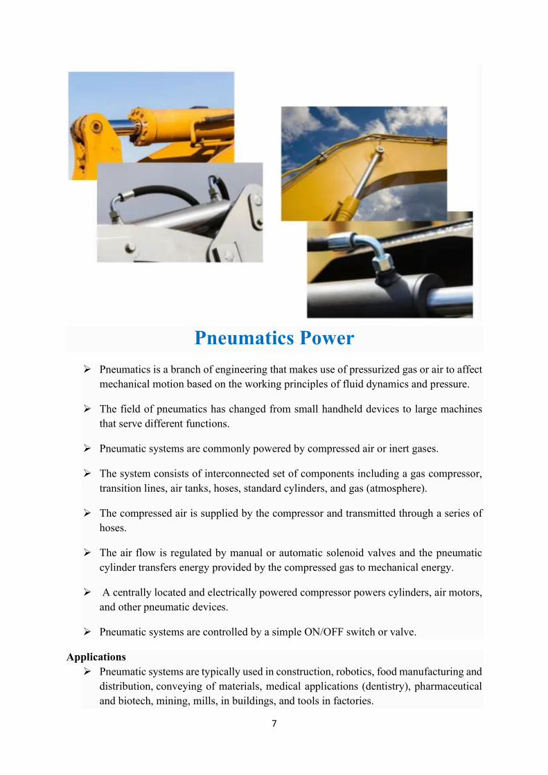
Pneumatics Power
Pneumatics is a branch of engineering that makes use of pressurized gas or air to affect mechanical motion based on the working principles of fluid dynamics and pressure.
The field of pneumatics has changed from small handheld devices to large machines that serve different functions.
Pneumatic systems are commonly powered by compressed air or inert gases.
The system consists of interconnected set of components including a gas compressor, transition lines, air tanks, hoses, standard cylinders, and gas (atmosphere).
The compressed air is supplied by the compressor and transmitted through a series of hoses.
The air flow is regulated by manual or automatic solenoid valves and the pneumatic cylinder transfers energy provided by the compressed gas to mechanical energy.
A centrally located and electrically powered compressor powers cylinders, air motors, and other pneumatic devices.
Pneumatic systems are controlled by a simple ON/OFF switch or valve.
Applications Pneumatic systems are typically used in construction, robotics, food manufacturing and
distribution, conveying of materials, medical applications (dentistry), pharmaceutical and biotech, mining, mills, in buildings, and tools in factories.
8
Pneumatic systems are primarily used for shock absorption applications because gas is compressible and allows the equipment to be less susceptible to shock damage.
Applications of pneumatic systems include:
Air compressors
Vacuum pumps
Compressed-air engines and vehicles
HVAC control systems
Conveyor systems in pharmaceutical and food industries
Pressure sensor, switch and pump
Precision drills used by dentists
Air brakes used by buses, trucks, and trains
Tampers used to pack down dirt and gravel
Nail guns
High pressure bank’s drive-teller tubes
Manufacturing and assembly lines
Pneumatic motor, tire, and tools
Advantages and Disadvantages of Pneumatics Pneumatic systems are selected above hydraulic systems because of the lower cost,
flexibility, and higher safety levels of the system. Pneumatic systems are best suited for applications which require no risk of
contamination because they offer a very clean environment for such industries as biotech, dentistry, pharmaceutical, and food suppliers.
Since they use clean, dry, compressed air, the system can quickly convey items. The straight and simple design prevents clogging and reduces maintenance. Pneumatic systems are easy to install and portable. They are reliable and has an initial low setup cost because they operate on
comparatively low pressure and inexpensive components that reduces operation costs. No container is required to store the air that will be compressed because it is drawn
from the surrounding atmosphere and filtered (optional). Safety is an important advantage of choosing Pneumatic systems. It is also maintenance free since there is little need to replace filters.

9
Element of mechanical transmission gears Machine elements used for transmitting the power: - Machine. elements like gears, shafts, clutches and brakes, pulleys, belts, chain, sprocket, are used to transmit power from one place to another. Requirements of Transmission System: - Provide means of connection and disconnection of engine with rest of power train
without shock and smoothly. Provide a varied leverage between the engine and the drive wheels Provide means to transfer power in opposite direction. Enable power transmission at varied angles and varied lengths. Enable speed reduction between engine and the drive wheels in the ratio of 5:1. Enable diversion of power flow at right angles. Provide means to drive the driving wheels at different speeds when required. Bear the effect of torque reaction, driving thrust and braking effort effectively.
GEARS Power transmission is the movement of energy from its place of generation to a location where it is applied to performing useful work. A gear is a component within a transmission device that transmits rotational force to another gear or device Types of Gears According to the position of axes of the shafts. Parallel
Spur Gear
Helical Gear
Herringbone Gear
Rack and Pinion Intersecting
Bevel Gear Non-intersecting and Non-parallel
worm and worm gears
CLUTCH Definition A clutch is a mechanical device that engages and disengages the power transmission, especially from driving shaft to drive shaft. Function of Clutch When the clutch is engaged, the power flows from the engine to the wheels through the
transmission system and the vehicle moves. When the clutch is disengaged, the power is not transmitted to the wheels and the
vehicles stops while the engine is still running. The clutch is kept engaged when the vehicle is moving.
10
The clutch also permits the gradual taking up of the load. When properly operated, it prevents jerky motion of the vehicle.
The clutch is disengaged: -
when starting the engine.
when shifting the gears.
when stopping the vehicle.
when idling the engine. Principle of Operation The clutch works on the principles of friction. When two friction surfaces are brought in contact with each other and pressed they are
united due to the friction between them. The friction between the three surfaces depends upon: -
Area of the surfaces.
applied pressure.
co-efficient of friction
The two surfaces can be separated and brought into contact when required.
One surface is considered as driving member and other as driven member
The driving member is kept rotating. Requirements of a clutch Torque transmission Gradual engagement Heat dissipation Dynamic balancing Vibration damping Size Free pedal play Easy in operation Lightness
Main parts of a clutch 1. Driving member 2. Driven member 3. Operating member
Driving member has a flywheel which is mounted on the engine crankshaft. A disc is bolted to flywheel which is known as pressure plate or driving disc.
The driven member is a disc called clutch plate. This plate can slide freely to and fro on the clutch shaft.
The operating member consists of a pedal or lever which can be pressed to disengage the driving and driven plate.
Types of clutch 1. Friction clutch: - (a) Single plate clutch b) Multi plate clutch - i) Wet ii) Dry c) Cone clutch – i) External ii) Internal
11
2. Centrifugal clutch 3. Electromagnetic Clutch 4.Vacuum Clutch 5. Hydraulic clutch
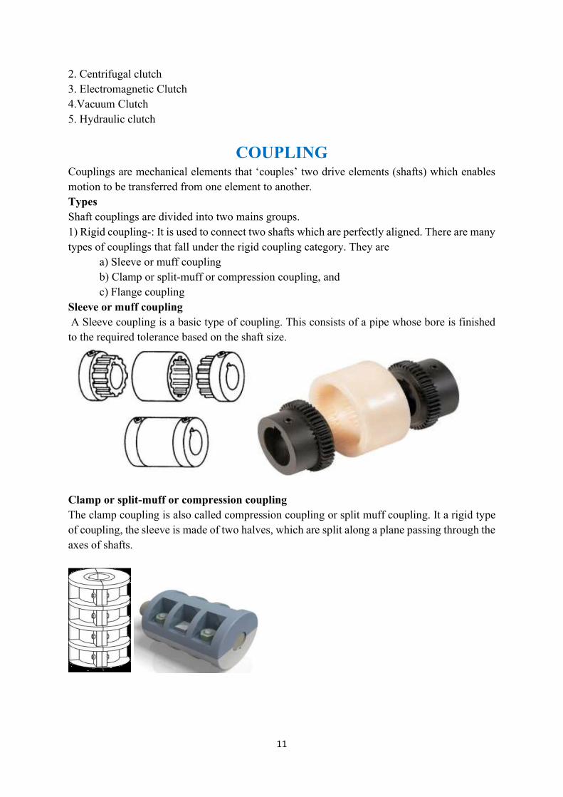
COUPLING Couplings are mechanical elements that ‘couples’ two drive elements (shafts) which enables motion to be transferred from one element to another. Types Shaft couplings are divided into two mains groups. 1) Rigid coupling-: It is used to connect two shafts which are perfectly aligned. There are many types of couplings that fall under the rigid coupling category. They are a) Sleeve or muff coupling b) Clamp or split-muff or compression coupling, and c) Flange coupling Sleeve or muff coupling A Sleeve coupling is a basic type of coupling. This consists of a pipe whose bore is finished to the required tolerance based on the shaft size.
Clamp or split-muff or compression coupling The clamp coupling is also called compression coupling or split muff coupling. It a rigid type of coupling, the sleeve is made of two halves, which are split along a plane passing through the axes of shafts.
12
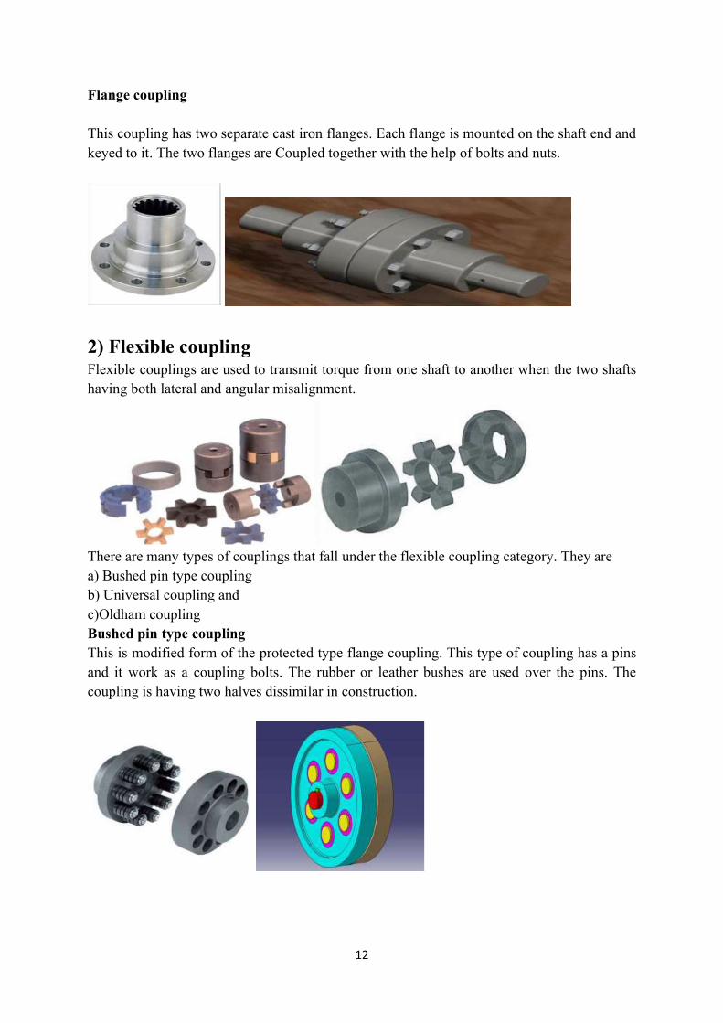
Flange coupling This coupling has two separate cast iron flanges. Each flange is mounted on the shaft end and keyed to it. The two flanges are Coupled together with the help of bolts and nuts.
2) Flexible coupling Flexible couplings are used to transmit torque from one shaft to another when the two shafts having both lateral and angular misalignment.
There are many types of couplings that fall under the flexible coupling category. They are a) Bushed pin type coupling b) Universal coupling and c)Oldham coupling Bushed pin type coupling This is modified form of the protected type flange coupling. This type of coupling has a pins and it work as a coupling bolts. The rubber or leather bushes are used over the pins. The coupling is having two halves dissimilar in construction.
13
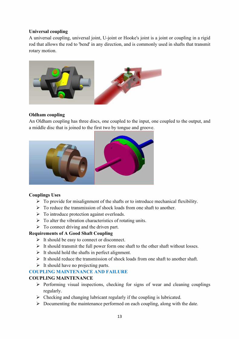
Universal coupling A universal coupling, universal joint, U-joint or Hooke's joint is a joint or coupling in a rigid rod that allows the rod to 'bend' in any direction, and is commonly used in shafts that transmit rotary motion.
Oldham coupling An Oldham coupling has three discs, one coupled to the input, one coupled to the output, and a middle disc that is joined to the first two by tongue and groove.
Couplings Uses To provide for misalignment of the shafts or to introduce mechanical flexibility. To reduce the transmission of shock loads from one shaft to another. To introduce protection against overloads. To alter the vibration characteristics of rotating units. To connect driving and the driven part.
Requirements of A Good Shaft Coupling It should be easy to connect or disconnect. It should transmit the full power form one shaft to the other shaft without losses. It should hold the shafts in perfect alignment. It should reduce the transmission of shock loads from one shaft to another shaft. It should have no projecting parts.
COUPLING MAINTENANCE AND FAILURE COUPLING MAINTENANCE Performing visual inspections, checking for signs of wear and cleaning couplings
regularly. Checking and changing lubricant regularly if the coupling is lubricated. Documenting the maintenance performed on each coupling, along with the date.

14
COUPLING FAILURE Improper installation. Poor coupling selection. Operation beyond design capabilities. Abnormal noise, such as screeching, squealing or chattering. Excessive vibration or wobble. Failed seals indicated by lubricant leakage or contamination.
BRAKES Introduction: Brakes are mechanical devices used for retarding the motion of a vehicle. Brakes are also used to stop the vehicle quickly within a short distance. Brakes are also used to hold the vehicle at rest on an inclined road against the pull of
gravity. Construction
Brake action starts as the brake pedal is depressed. Two sets of members constitute the brake of every vehicle.
One member is directly connected to the axle shaft and thus it becomes a rotating member.
The second member is attached to the frame or axle housing and thus it acts as the stationary member.
The brake works by causing friction between the non-rotating member and the disc or drum that turns with the road wheel.
Friction produces the force required to slow down the vehicle. By means of friction, the brake converts the power of momentum (kinetic energy) of the vehicle into heat.
The heat produced, disappears into the air around the brakes. Different arrangements of breaking a rotating wheel can be seen in figures given below.
A) Wagon wheel brake is used in rail wagons. B) External contracting brake is used in rail wagons. C) Internal expanding shoe brake is used intensively in automotive vehicles Principle of brake A moving vehicle possesses kinetic energy that is converted into heat energy on the
application of brakes. This heat is transferred to the surrounding air.
15
In the simplest form, a brake comprises a stationary brake shoe with a friction lining on it and a brake drum.
The road wheel is fixed to the rotating brake drum. The driver applies force on the brake pedal that gets amplified and pushes the stationary
shoe to make contact with the brake drum and stops its rotation due to frictional resistance.
The heat generated due to braking action is proportional to the force that brings the shoe in contact with the drum.
Purpose of Brakes The main purposes of fitting brakes on motor vehicle are as given under. In emergencies to bring the vehicle to rest in the shortest possible distance. To control the vehicle when it is in the hills. To keep the vehicle in desired position after bringing it in complete rest when there is
no driver. To full fill the above needs two independent braking systems are provided in the vehicle. (a) "Service brake" which is operated by foot pedal in general during regular operation. (b)"Emergency brake" which is operated by a hand lever while parking the vehicle. Requirements of Brake Brakes, in general, are required to slow, stop or hold the vehicle and convert the kinetic energy of motion into heat and then to dissipate this heat Application of brakes should bring the vehicle to a relatively quick to stop on any type
of road-wet, dry, even, uneven, uphill or downhill. This has to be achieved at any speed, laden or unladen.
A separate mechanical brake is required to hold the vehicle in position on a gradient. The braking system components must require minimum maintenance. The pedal effort required to produce maximum deceleration should be minimum and
should not vary with the condition of the road. The braking system should allow minimum time between application of pedal effort
and actual braking effect on the drum. The braking action should not involve any noise, or drift the vehicle away from its
desired path. Provisions for quick heat dissipation must be incorporated. A secondary braking system must be incorporated, should the primary braking system
fail.
Types of Brakes 1. DRUM BRAKE 2. DISC BRAKE Drum Brake • It may be 1. Internal expanding and 2. External expanding.
16
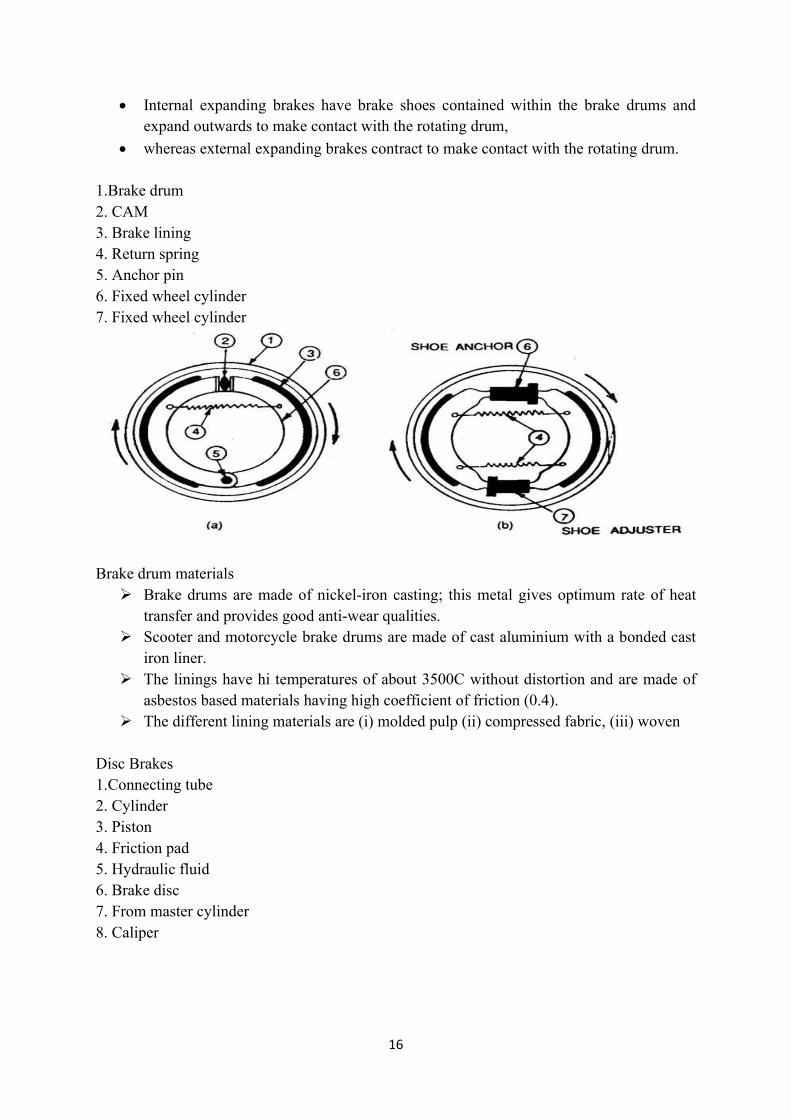
Internal expanding brakes have brake shoes contained within the brake drums and expand outwards to make contact with the rotating drum,
whereas external expanding brakes contract to make contact with the rotating drum. 1.Brake drum 2. CAM 3. Brake lining 4. Return spring 5. Anchor pin 6. Fixed wheel cylinder 7. Fixed wheel cylinder
Brake drum materials Brake drums are made of nickel-iron casting; this metal gives optimum rate of heat
transfer and provides good anti-wear qualities. Scooter and motorcycle brake drums are made of cast aluminium with a bonded cast
iron liner. The linings have hi temperatures of about 3500C without distortion and are made of
asbestos based materials having high coefficient of friction (0.4). The different lining materials are (i) molded pulp (ii) compressed fabric, (iii) woven
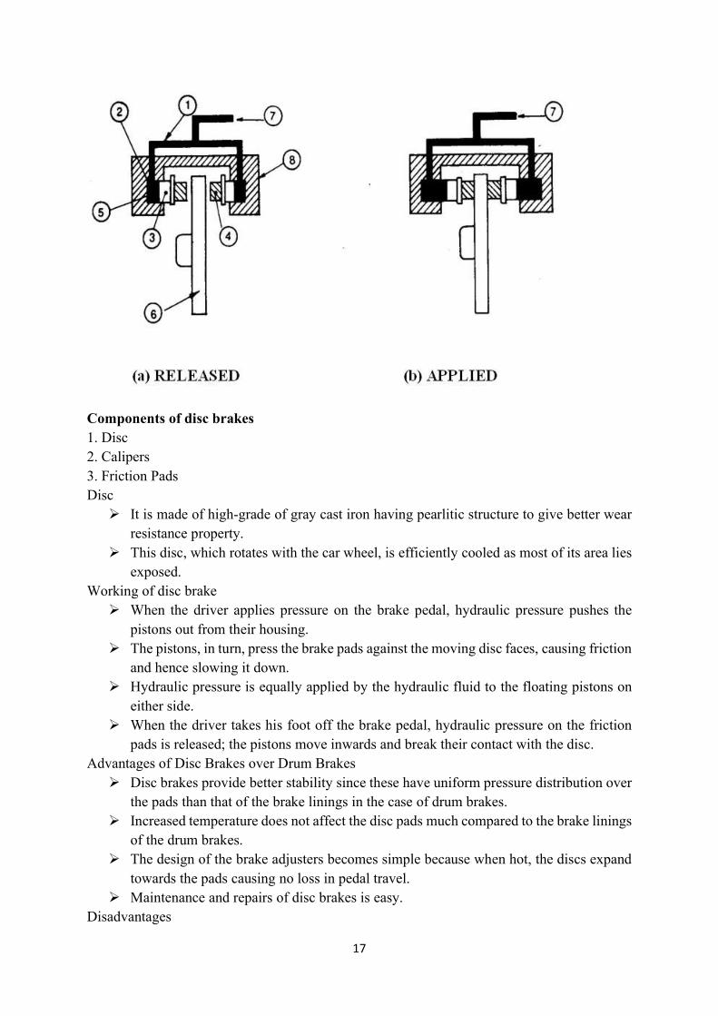
Disc Brakes 1.Connecting tube 2. Cylinder 3. Piston 4. Friction pad 5. Hydraulic fluid 6. Brake disc 7. From master cylinder 8. Caliper
17
Components of disc brakes 1. Disc 2. Calipers 3. Friction Pads Disc It is made of high-grade of gray cast iron having pearlitic structure to give better wear
resistance property. This disc, which rotates with the car wheel, is efficiently cooled as most of its area lies
exposed. Working of disc brake When the driver applies pressure on the brake pedal, hydraulic pressure pushes the
pistons out from their housing. The pistons, in turn, press the brake pads against the moving disc faces, causing friction
and hence slowing it down. Hydraulic pressure is equally applied by the hydraulic fluid to the floating pistons on
either side. When the driver takes his foot off the brake pedal, hydraulic pressure on the friction
pads is released; the pistons move inwards and break their contact with the disc. Advantages of Disc Brakes over Drum Brakes Disc brakes provide better stability since these have uniform pressure distribution over
the pads than that of the brake linings in the case of drum brakes. Increased temperature does not affect the disc pads much compared to the brake linings
of the drum brakes. The design of the brake adjusters becomes simple because when hot, the discs expand
towards the pads causing no loss in pedal travel. Maintenance and repairs of disc brakes is easy.
Disadvantages

18
Disc brake assemblies are costlier than drum brakes. The pads wear off fast compared to brake shoe linings of drum brakes. Disc brakes have
higher brake pressures. Complete protection to the disc from road residue is provided with great difficulty. The high temperature operation of disc brakes causes evaporation of the brake fluid and
weakening of seal. In the case of cars fitted with disc brakes, an external servo mechanism is required
because these have no self-energizing effect, Such an arrangement is not required in cars having drum brakes.
Handbrakes can be installed on drum brakes because these have self-energizing effect. Disc brakes offer difficulty in installing hand brakes.