da98 - despin sa
TRANSCRIPT
High-performance Super-small Dimension
DA98
Fully digitize AC servo amplifier
Installation and Operation Manual
Guangzhou Numerical Control Equipment Factory, China
2000, 6, 1
PREFACE Thank you for choosing this DA98 AC servo system. This user guide gives comprehensible information and precautions for using the servo drive.
Incorrect handling may cause an unexpected accident. Before using the servo drive, please read this manual carefully. ● Due to improvement of the product the contents of this manual may be changed at any time
without further notice. ● Our factory does not assume any responsibility for any reform of the product by customer. If
so, the product guarantee form is not valid any more. When read this manual; please pay more attention to the following warning symbols:
Indicates that incorrect handling may cause ngerous consequences resulting in death or severe
injury. da ! WARNING
Indicates that incorrect handling may cause injury
the operator and may cause equipment damage. to
Indicates that incorrect handling may cause the servo amplifier and other equipment to be faulty or damage.
! CAUTION
! NOTICE
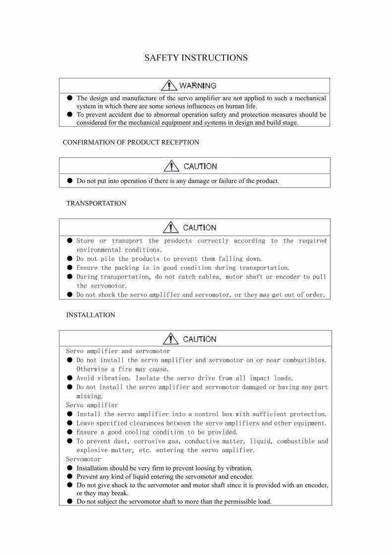
SAFETY INSTRUCTIONS
● The design and manufacture of the servo amplifier are not applied to such a mechanical system in which there are some serious influences on human life.
● To prevent accident due to abnormal operation safety and protection measures should be considered for the mechanical equipment and systems in design and build stage.
CONFIRMATION OF PRODUCT RECEPTION
● Do not put into operation if there is any damage or failure of the product.
TRANSPORTATION
● Store or transport the products correctly according to the required
environmental conditions.
● Do not pile the products to prevent them falling down. ● Ensure the packing is in good condition during transportation. ● During transportation, do not catch cables, motor shaft or encoder to pull
the servomotor. ● Do not shock the servo amplifier and servomotor, or they may get out of order.
INSTALLATION
Servo amplifier and servomotor
● Do not install the servo amplifier and servomotor on or near combustibles.
Otherwise a fire may cause.
● Avoid vibration. Isolate the servo drive from all impact loads.
● Do not install the servo amplifier and servomotor damaged or having any part
missing.
Servo amplifier
● Install the servo amplifier into a control box with sufficient protection.
● Leave specified clearances between the servo amplifiers and other equipment.
● Ensure a good cooling condition to be provided.
● To prevent dust, corrosive gas, conductive matter, liquid, combustible and
explosive matter, etc. entering the servo amplifier.
Servomotor ● Installation should be very firm to prevent loosing by vibration. ● Prevent any kind of liquid entering the servomotor and encoder. ● Do not give shock to the servomotor and motor shaft since it is provided with an encoder,
or they may break. ● Do not subject the servomotor shaft to more than the permissible load.
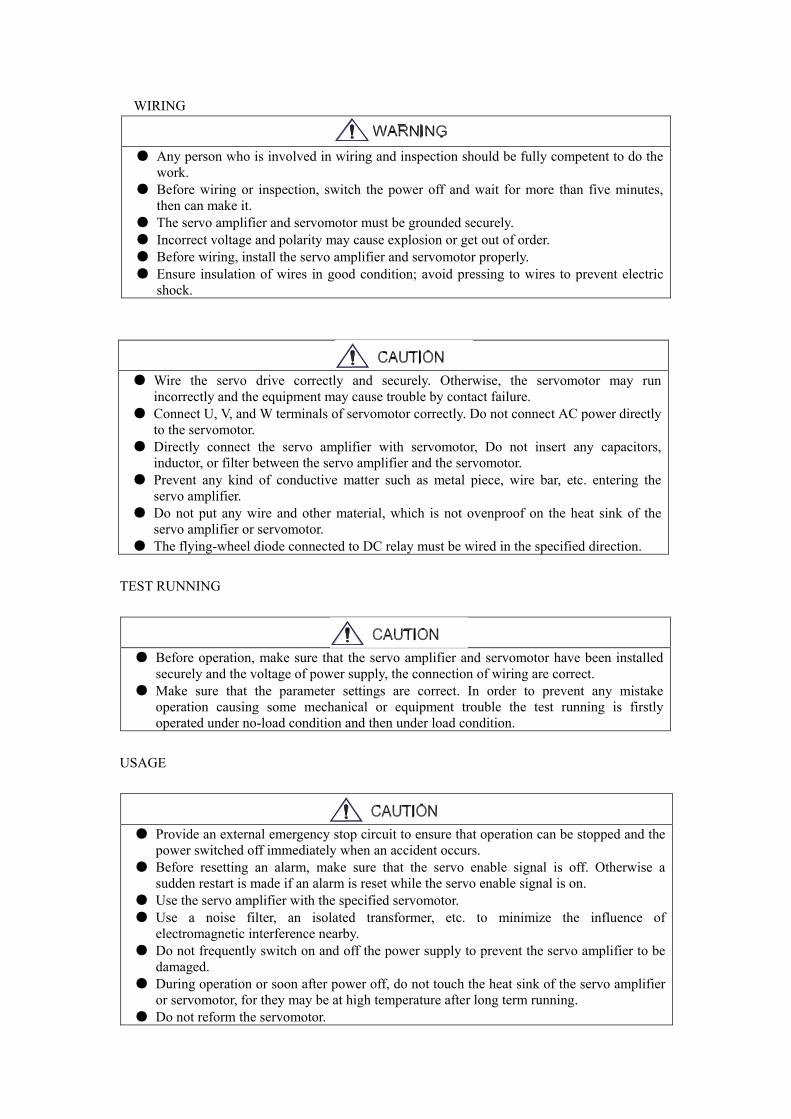
WIRING
● Any person who is involved in wiring and inspection should be fully competent to do the work.
● Before wiring or inspection, switch the power off and wait for more than five minutes, then can make it.
● The servo amplifier and servomotor must be grounded securely. ● Incorrect voltage and polarity may cause explosion or get out of order. ● Before wiring, install the servo amplifier and servomotor properly. ● Ensure insulation of wires in good condition; avoid pressing to wires to prevent electric
shock.
● Wire the servo drive correctly and securely. Otherwise, the servomotor may run incorrectly and the equipment may cause trouble by contact failure.
● Connect U, V, and W terminals of servomotor correctly. Do not connect AC power directly to the servomotor.
● Directly connect the servo amplifier with servomotor, Do not insert any capacitors, inductor, or filter between the servo amplifier and the servomotor.
● Prevent any kind of conductive matter such as metal piece, wire bar, etc. entering the servo amplifier.
● Do not put any wire and other material, which is not ovenproof on the heat sink of the servo amplifier or servomotor.
● The flying-wheel diode connected to DC relay must be wired in the specified direction. TEST RUNNING
● Before operation, make sure that the servo amplifier and servomotor have been installed securely and the voltage of power supply, the connection of wiring are correct.
● Make sure that the parameter settings are correct. In order to prevent any mistake operation causing some mechanical or equipment trouble the test running is firstly operated under no-load condition and then under load condition.
USAGE
● Provide an external emergency stop circuit to ensure that operation can be stopped and the power switched off immediately when an accident occurs.
● Before resetting an alarm, make sure that the servo enable signal is off. Otherwise a sudden restart is made if an alarm is reset while the servo enable signal is on.
● Use the servo amplifier with the specified servomotor. ● Use a noise filter, an isolated transformer, etc. to minimize the influence of
electromagnetic interference nearby. ● Do not frequently switch on and off the power supply to prevent the servo amplifier to be
damaged. ● During operation or soon after power off, do not touch the heat sink of the servo amplifier
or servomotor, for they may be at high temperature after long term running. ● Do not reform the servomotor.
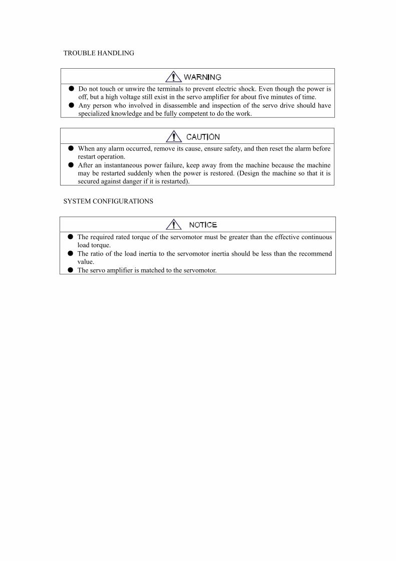
TROUBLE HANDLING
● Do not touch or unwire the terminals to prevent electric shock. Even though the power is off, but a high voltage still exist in the servo amplifier for about five minutes of time.
● Any person who involved in disassemble and inspection of the servo drive should have specialized knowledge and be fully competent to do the work.
● When any alarm occurred, remove its cause, ensure safety, and then reset the alarm before restart operation.
● After an instantaneous power failure, keep away from the machine because the machine may be restarted suddenly when the power is restored. (Design the machine so that it is secured against danger if it is restarted).
SYSTEM CONFIGURATIONS
● The required rated torque of the servomotor must be greater than the effective continuous load torque.
● The ratio of the load inertia to the servomotor inertia should be less than the recommend value.
● The servo amplifier is matched to the servomotor.
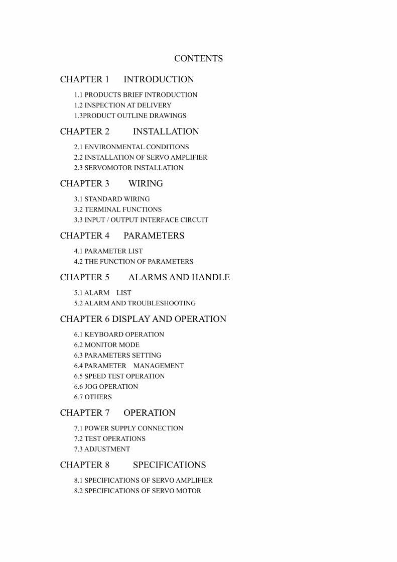
CONTENTS
CHAPTER 1 INTRODUCTION 1.1 PRODUCTS BRIEF INTRODUCTION 1.2 INSPECTION AT DELIVERY 1.3PRODUCT OUTLINE DRAWINGS
CHAPTER 2 INSTALLATION 2.1 ENVIRONMENTAL CONDITIONS 2.2 INSTALLATION OF SERVO AMPLIFIER 2.3 SERVOMOTOR INSTALLATION
CHAPTER 3 WIRING 3.1 STANDARD WIRING 3.2 TERMINAL FUNCTIONS 3.3 INPUT / OUTPUT INTERFACE CIRCUIT
CHAPTER 4 PARAMETERS 4.1 PARAMETER LIST 4.2 THE FUNCTION OF PARAMETERS
CHAPTER 5 ALARMS AND HANDLE 5.1 ALARM LIST
5.2 ALARM AND TROUBLESHOOTING
CHAPTER 6 DISPLAY AND OPERATION 6.1 KEYBOARD OPERATION 6.2 MONITOR MODE
6.3 PARAMETERS SETTING 6.4 PARAMETER MANAGEMENT
6.5 SPEED TEST OPERATION 6.6 JOG OPERATION 6.7 OTHERS
CHAPTER 7 OPERATION 7.1 POWER SUPPLY CONNECTION 7.2 TEST OPERATIONS 7.3 ADJUSTMENT
CHAPTER 8 SPECIFICATIONS 8.1 SPECIFICATIONS OF SERVO AMPLIFIER 8.2 SPECIFICATIONS OF SERVO MOTOR

8.3 ISOLATED TRANSFORMERS
CHAPTER 9 ORDER GUIDELINE
9.1 CAPACITY SELECTION 9.2 ELETRIC GEAR RATIO 9.3 STOPPING CHARACTERISTICS

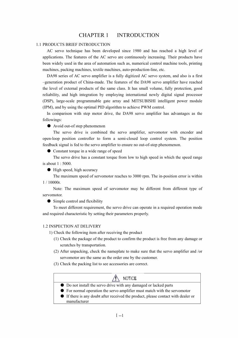
CHAPTER 1 INTRODUCTION 1.1 PRODUCTS BRIEF INTRODUCTION
AC servo technique has been developed since 1980 and has reached a high level of applications. The features of the AC servo are continuously increasing. Their products have been widely used in the area of automation such as, numerical control machine tools, printing machines, packing machines, textile machines, auto-production-line, etc. DA98 series of AC servo amplifier is a fully digitized AC servo system, and also is a first –generation product of China-made. The features of the DA98 servo amplifier have reached the level of external products of the same class. It has small volume, fully protection, good reliability, and high integration by employing international newly digital signal processor (DSP), large-scale programmable gate array and MITSUBISHI intelligent power module (IPM), and by using the optimal PID algorithm to achieve PWM control. In comparison with step motor drive, the DA98 servo amplifier has advantages as the followings: ● Avoid out-of step phenomenon The servo drive is combined the servo amplifier, servomotor with encoder and open-loop position controller to form a semi-closed loop control system. The position feedback signal is fed to the servo amplifier to ensure no out-of-step phenomenon. ● Constant torque in a wide range of speed The servo drive has a constant torque from low to high speed in which the speed range is about 1 : 5000. ● High speed, high accuracy The maximum speed of servomotor reaches to 3000 rpm. The in-position error is within 1 / 10000r. Note: The maximum speed of servomotor may be different from different type of servomotor. ● Simple control and flexibility To meet different requirement, the servo drive can operate in a required operation mode and required characteristic by setting their parameters properly. 1.2 INSPECTION AT DELIVERY
1) Check the following item after receiving the product (1) Check the package of the product to confirm the product is free from any damage or
scratches by transportation. (2) After unpacking, check the nameplate to make sure that the servo amplifier and /or
servomotor are the same as the order one by the customer. (3) Check the packing list to see accessories are correct.
● Do not install the servo drive with any damaged or lacked parts ● For normal operation the servo amplifier must match with the servomotor ● If there is any doubt after received the product, please contact with dealer or manufacturer
Ⅰ--1
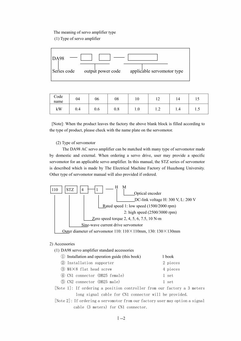
The meaning of servo amplifier type (1) Type of servo amplifier
DA98 Series code output power code applicable servomotor type
Code name 04 06 08 10 12 14 15
kW 0.4 0.6 0.8 1.0 1.2 1.4 1.5
[Note]: When the product leaves the factory the above blank block is filled according to the type of product, please check with the name plate on the servomotor. (2) Type of servomotor The DA98 AC servo amplifier can be matched with many type of servomotor made by domestic and external. When ordering a servo drive, user may provide a specific servomotor for an applicable servo amplifier. In this manual, the STZ series of servomotor is described which is made by The Electrical Machine Factory of Huazhong University. Other type of servomotor manual will also provided if ordered.
H M Optical encoder
DC-link voltage H: 300 V, L: 200 V Rated speed 1: low speed (1500/2000 rpm) 2: high speed (2500/3000 rpm) Zero speed torque 2, 4, 5, 6, 7.5, 10 N-m Sine-wave current drive servomotor Outer diameter of servomotor 110: 110×110mm, 130: 130×130mm
110 4 1 STZ
2) Accessories
(1) DA98 servo amplifier standard accessories ① Installation and operation guide (this book) 1 book ② Installation supporter 2 pieces
③ M4×8 flat head screw 4 pieces
④ CN1 connector (DB25 female) 1 set
⑤ CN2 connector (DB25 male) 1 set
[Note 1]: If ordering a position controller from our factory a 3 meters
long signal cable for CN1 connector will be provided.
[Note 2]: If ordering a servomotor from our factory user may option a signal
cable (3 meters) for CN1 connector.
Ⅰ--2
(2) The standard accessories of servomotor are provided according to the
user’s manual of the servomotor.
1.3 PRODUCT OUTLINE DRAWINGS 1) The outline drawing of the servo amplifier 2) The outline drawing of the servomotor
Ⅰ--3
CHAPTER 2 INSTALLATION
● Store and install of the product must meet requirements of environmental conditions ● Do not pile the products too much to prevent damage from pressing or falling. ● Original product package must be used when transportation is again needed. ● Do not install and use if the product has been damaged or has any missing parts. ● Use fireproofing material for installation and keep away from flammable matter in case to prevent on fire. ● The servo amplifier must be installed inside a cabinet to keep free from dust, corrupt gas, liquid, conductance and easy burning matter. ● The servo amplifier and serve motor must keep away from vibration source and isolate from all impact. ● Do not carry the servo motor by dragging the motor shaft, cables of motor or encoder.
2.1 ENVIRONMENTAL CONDITIONS Item DA98 drive amplifier STZ series servomotor Ambient temperature Ambient humidity
0~55 0C (non-freezing) 90% RH or less (non-condensing)
0~40 0C (non- freezing) 90% RH or less (non- condensing)
Storage temperature Storage humidity
-20~800C 90% RH (non-condensing)
-25~70 0C <80% RH (non-condensing)
Ambience Free from corrosive gas, flammable gas, oil mist, dust and dirt etc.
Free from corrosive gas, flammable gas, oil mist, dust and dirt etc.
Altitude 1000m or less (above sea level) 2500m or less (above sea level)
Vibration < 0.5G(4.9m/s2) 10~60 Hz (non continuous operation)
Protection class IP00(non-protection) IP40
2.2 INSTALLATION OF SERVO AMPLIFIER
● The servo amplifier must be installed in a control cabinet with good protection condition. ● The servo amplifier must be installed in the specified direction and kept enough space between
the drive unit and control box walls or other equipment to guarantee the condition of heat transmission.
● Do not install the drive unit on or nearby flammable matters to prevent causing fire.
1) Environmental conditions for installation
(1) Protections The servo amplifier must be installed in a control cabinet with good protection condition due to the drive unit has non-protection and kept free from corrosive gas, flammable gas, oil mist, metal dust, liquid and conductance matters etc.
Ⅱ--1
(2) Temperature Ambient temperature 0~50 0C and under 45 0C for continuous operation with guarantee the condition of heat transmission.
(3) Vibration and impact Installation must ensure no harm vibration otherwise reduce vibration means must be taken for reducing vibration under 0.5G(4.9 m/s2). Do not put heavy objects on the servo amplifier and avoid impact
2) Installation method (1) Installation manner
There are two manners of installation can be used, the first one is the rear plate mounting and the second is the front-panel plate mounting. The installation direction is perpendicular to the mounted plate. Figure 2.1 shows the rear plate mounting. Figure 2.2 shows the front-panel plate mounting. Figure 2.1 Servo amplifier rear plate mounting. Figure 2.2 Servo amplifier front-panel plate mounting.
(2) Installation clearances
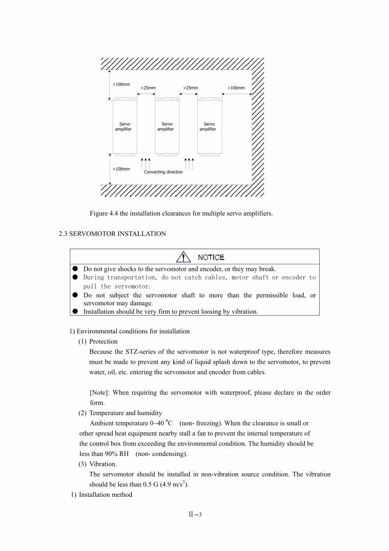
Figure 2.3 shows the installation clearances for a single servo amplifier. Figure 2.4 shows the installation clearances for multiple servo amplifiers. In practice, to ensure a good cooling condition, provide installation clearances around the servo amplifiers as large as possible. Figure 2.3 the installation clearances for a single servo amplifier.
Ⅱ--2
>100mm
>100mm
>100mm>25mm >25mm
Convecting direction
Servoamplifier
Servoamplifier
Servoamplifier
Figure 4.4 the installation clearances for multiple servo amplifiers.
2.3 SERVOMOTOR INSTALLATION
● Do not give shocks to the servomotor and encoder, or they may break. ● During transportation, do not catch cables, motor shaft or encoder to
pull the servomotor. ● Do not subject the servomotor shaft to more than the permissible load, or
servomotor may damage. ● Installation should be very firm to prevent loosing by vibration.
1) Environmental conditions for installation
(1) Protection Because the STZ-series of the servomotor is not waterproof type, therefore measures must be made to prevent any kind of liquid splash down to the servomotor, to prevent water, oil, etc. entering the servomotor and encoder from cables. [Note]: When requiring the servomotor with waterproof, please declare in the order form.
(2) Temperature and humidity Ambient temperature 0~40 0C (non- freezing). When the clearance is small or other spread heat equipment nearby stall a fan to prevent the internal temperature of the control box from exceeding the environmental condition. The humidity should be less than 90% RH (non- condensing).
(3) Vibration. The servomotor should be installed in non-vibration source condition. The vibration should be less than 0.5 G (4.9 m/s2).
1) Installation method
Ⅱ--3
(1) Installation manner A flange mounting type is used for the STZ series servomotor and can be installed in any direction. (2) Cautions of installation
● When mounting (or removing) a pulley to (or from) the servomotor shaft, use the screw push-pull tools to protect the shaft from impact. The shaft end must not be hammered. Otherwise, the encoder may damage.
● It is recommended that use a springing coupling to connect the load because the STZ series servomotor subject large axial or radial load to the shaft of the servomotor.
● Use the lock washer to fix the servomotor to protect the servomotor from loosing.
Ⅱ--4
CHAPTER 3 WIRING
● Any person who is involved in wiring or checking should be fully competent to do the work. ● Before wiring or checking, make sure that the voltage is safe at lest 5 minutes after
power-off. Otherwise you may get an electric shock.
● Connect cables to correct terminals according to voltage level and polarity to prevent equipment damage or person injury.
● The protective earth terminals (PE, FG) should be connected to ground.
3.1 STANDARD WIRING Connections of the servo amplifier are related to the control mode as following:
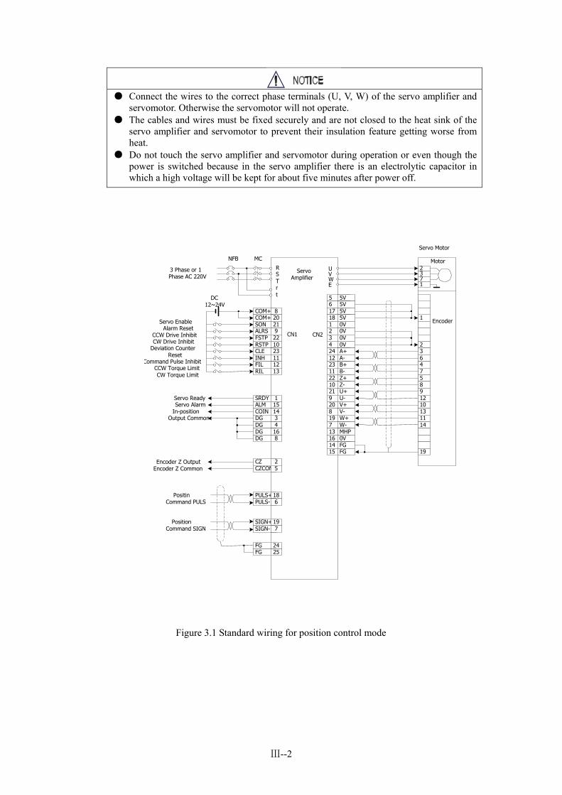
1) Position control mode: The standard wiring for position control mode is shown in FIG.3.1
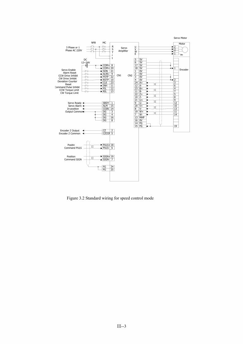
2) Velocity control mode: The standard wiring for velocity control mode is shown in FIG.3.2 3) wiring
(1) Power terminals TB ● Wire size: R, S, T, PE, U, V, W terminal wire size => 1.5 mm^2 (AGW 14~16), r, t terminal
wire size => 1.0 mm^2 (AGW 16~18). ● Grounding: The wire size for grounding is as bigger as possible. The PE terminals of the servo
amplifier and servomotor are connected to the ground in one point. The grounding resistant should be less than 100 OMS.
● JUT-1.5—4 pre-insulated terminal is used for connecting wire terminals and make sure that the connections are fast.
● A phase isolated transformer for power supply is recommended to reducing possibility of electric shock.
● A noise filter in series with power supply is recommended to enhance the ability of anti-interference.
● Please install a non-melt type breaker (NFB) to switch off power supply quickly in case of the servo amplifier failure.
(2) Control signals CN1, Encoder signals CN2 ● Wire size: Use a screened cable (screened twisted pair type is best), wire size>=0.12mm2
(AWG24~26). The screening wire must be connected to PE (FG) terminal. ● Cable length: The length of cable is shorter as possible. The length of control cable CN1 is
three meters or less. The length of encoder cable is 20 meters or less. ● Wire distribution: The cable wiring must be kept away from power wiring to prevent the
influence of electromagnetic interference. ● Please provide a surge voltage snubber component to each inductance (coil) in related circuit.
A direct current coil is connected with an anti-parallel flywheel diode and an AC coil is connected with a RC snubber circuit.
Ⅲ--1
● Connect the wires to the correct phase terminals (U, V, W) of the servo amplifier and servomotor. Otherwise the servomotor will not operate.
● The cables and wires must be fixed securely and are not closed to the heat sink of the servo amplifier and servomotor to prevent their insulation feature getting worse from heat.
● Do not touch the servo amplifier and servomotor during operation or even though the power is switched because in the servo amplifier there is an electrolytic capacitor in which a high voltage will be kept for about five minutes after power off.
Figure 3.1 Standard wiring for position control mode
3 Phase or 1Phase AC 220V
NFB MC
RSTrt
COM+ 8COM+ 20SON 21ALRS 9FSTP 22RSTP 10CLE 23INH 11FIL 12RIL 13
DC12~24V
Servo EnableAlarm Reset
CCW Drive Inhibit
Deviation CounterReset
CW Drive Inhibit
Command Pulse InhibitCCW Torque LimitCW Torque Limit
SRDY 1ALM 15COIN 14DG 3DG 4DG 16DG 8
CZ 2CZCOM 5
Servo ReadyServo Alarm
In-positionOutput Common
Encoder Z OutputEncoder Z Common
PULS+ 18PULS- 6
SIGN+ 19SIGN- 7
PositinCommand PULS
PositionCommand SIGN
FG 24FG 25
UVWE
5 5V6 5V17 5V18 5V1 0V2 0V3 0V4 0V24 A+12 A-23 B+11 B-22 Z+10 Z-21 U+9 U-20 V+8 V-19 W+7 W-13 MHP16 0V14 FG15 FG
CN1 CN2
2371
1
236475891210131114
19
Encoder
Motor
ServoAmplifier
Servo Motor
Ⅲ--2
3 Phase or 1Phase AC 220V
NFB MC
RSTrt
COM+ 8COM+ 20SON 21ALRS 9FSTP 22RSTP 10CLE 23INH 11FIL 12RIL 13
DC12~24V
Servo EnableAlarm Reset
CCW Drive Inhibit
Deviation CounterReset
CW Drive Inhibit
Command Pulse InhibitCCW Torque LimitCW Torque Limit
SRDY 1ALM 15COIN 14DG 3DG 4DG 16DG 8
CZ 2CZCOM 5
Servo ReadyServo Alarm
In-positionOutput Common
Encoder Z OutputEncoder Z Common
PULS+ 18PULS- 6
SIGN+ 19SIGN- 7
PositinCommand PULS
PositionCommand SIGN
FG 24FG 25
UVWE
5 5V6 5V17 5V18 5V1 0V2 0V3 0V4 0V24 A+12 A-23 B+11 B-22 Z+10 Z-21 U+9 U-20 V+8 V-19 W+7 W-13 MHP16 0V14 FG15 FG
CN1 CN2
2371
1
236475891210131114
19
Encoder
Motor
ServoAmplifier
Servo Motor
Figure 3.2 Standard wiring for speed control mode
Ⅲ--3

3.2 TERMINAL FUNCTIONS 1) Arrangement of connection terminals
Figure 3.3 is arrangement of connection terminal for the servo amplifier. Where, TB is the terminal block.. CN1 is DB25 connector. The socket is male and the plug is female. CN2 is DB25 connector. The socket is female and the plug is male.
R
S
T
E
U
V
W
P
D
r
t
TB11421531641751861972082192210231124122513
CN1
DB25
11421531641751861972082192210231124122513
CN2
DB25
COM+
ALM
COIN/SCMPCZ
SRDY
DGDGDGDGCZCOMPULS+PULS-SIGN+SIGN-COM+
SONALRSFSTPRSTPCLE/SC1INH/SC2FGFILFGRIL
MHPNCA-A+B-B+Z-Z+U-U+V-V+W-W++5V+5V+5V+5V0V0V0VFG0VFG0V
2) Power terminal block Table 3.1 Power terminal block
Terminal number
symbol Name of signal function
TB-1 R TB-2 S TB-3 T
Main power supply One phase or three
phases
Main power input terminals. ~220V, 50Hz. Note: Never connect R, S, T to U, V, W terminals of the servomotor.
TB-4 PE System ground Grounding terminal Grounding resistance < 100 Ω; Connect with input power ground to form a common point
TB-5 U TB-6 V TB-7 W
Servo amplifier outputs
Servo amplifier output terminals. Connections must match with U, V, W terminals of the servomotor
TB-8 P Reserved TB-9 D Reserved TB-10 r TB-11 t
Control power supply Single phase
Control circuit power supply terminals ~220V, 50 Hz
3) Control signal terminals CN1
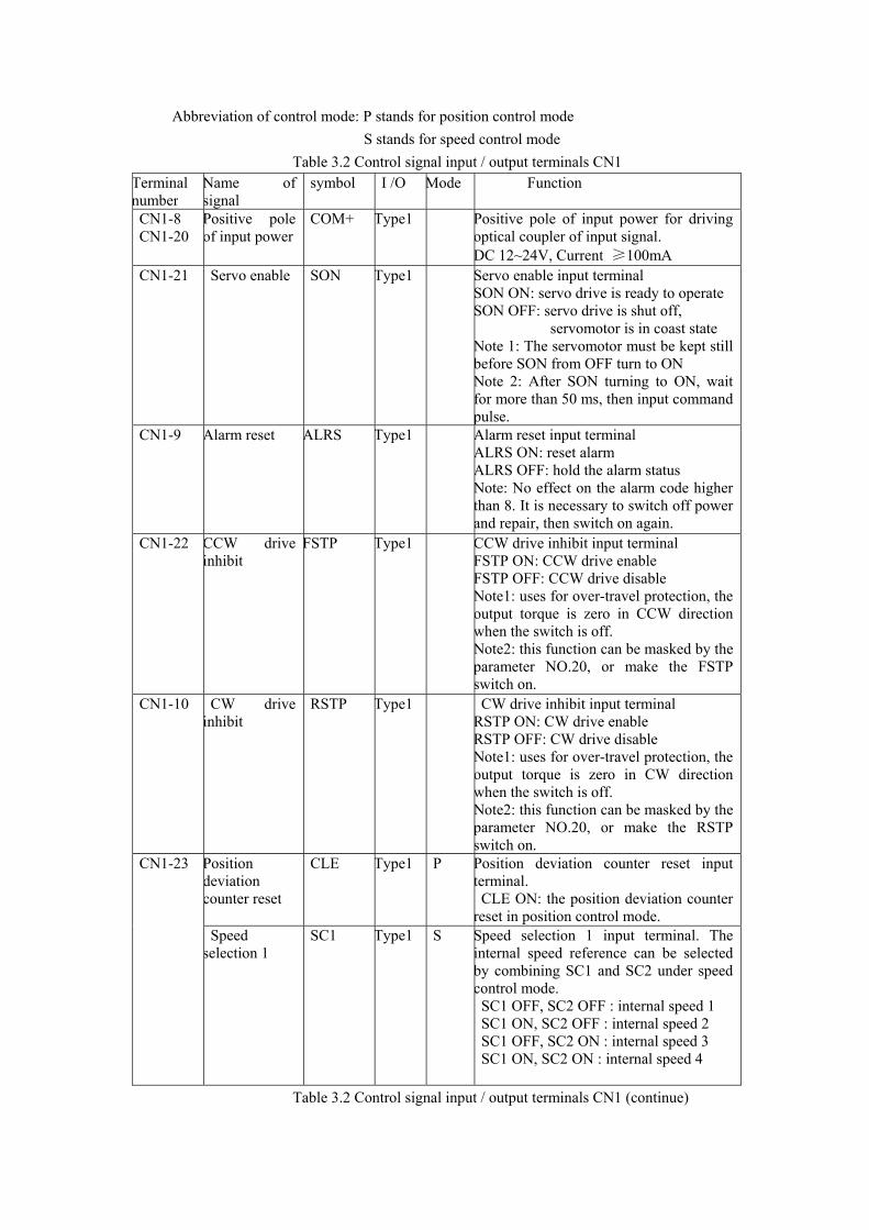
Abbreviation of control mode: P stands for position control mode S stands for speed control mode
Table 3.2 Control signal input / output terminals CN1 Terminal number
Name of signal
symbol I /O Mode Function
CN1-8 CN1-20
Positive pole of input power
COM+ Type1 Positive pole of input power for driving optical coupler of input signal. DC 12~24V, Current ≥100mA
CN1-21 Servo enable SON Type1 Servo enable input terminal SON ON: servo drive is ready to operate SON OFF: servo drive is shut off,
servomotor is in coast state Note 1: The servomotor must be kept still before SON from OFF turn to ON Note 2: After SON turning to ON, wait for more than 50 ms, then input command pulse.
CN1-9 Alarm reset ALRS Type1 Alarm reset input terminal ALRS ON: reset alarm ALRS OFF: hold the alarm status Note: No effect on the alarm code higher than 8. It is necessary to switch off power and repair, then switch on again.
CN1-22 CCW drive inhibit
FSTP Type1 CCW drive inhibit input terminal FSTP ON: CCW drive enable FSTP OFF: CCW drive disable Note1: uses for over-travel protection, the output torque is zero in CCW direction when the switch is off. Note2: this function can be masked by the parameter NO.20, or make the FSTP switch on.
CN1-10 CW drive inhibit
RSTP Type1 CW drive inhibit input terminal RSTP ON: CW drive enable RSTP OFF: CW drive disable Note1: uses for over-travel protection, the output torque is zero in CW direction when the switch is off. Note2: this function can be masked by the parameter NO.20, or make the RSTP switch on.
Position deviation counter reset
CLE Type1 P Position deviation counter reset input terminal.
CLE ON: the position deviation counter reset in position control mode.
CN1-23
Speed selection 1
SC1 Type1 S Speed selection 1 input terminal. The internal speed reference can be selected by combining SC1 and SC2 under speed control mode.
SC1 OFF, SC2 OFF : internal speed 1 SC1 ON, SC2 OFF : internal speed 2 SC1 OFF, SC2 ON : internal speed 3 SC1 ON, SC2 ON : internal speed 4
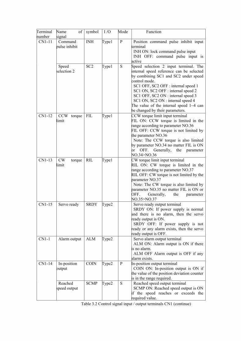
Table 3.2 Control signal input / output terminals CN1 (continue)
Terminal number
Name of signal
symbol I /O Mode Function
Command pulse inhibit
INH Type1 P Position command pulse inhibit input terminal
INH ON: lock command pulse input INH OFF: command pulse input is
active
CN1-11
Speed selection 2
SC2 Type1 S Speed selection 2 input terminal. The internal speed reference can be selected by combining SC1 and SC2 under speed control mode.
SC1 OFF, SC2 OFF : internal speed 1 SC1 ON, SC2 OFF : internal speed 2 SC1 OFF, SC2 ON : internal speed 3 SC1 ON, SC2 ON : internal speed 4
The value of the internal speed 1~4 can be changed by their parameters.
CN1-12 CCW torque limit
FIL Type1 CCW torque limit input terminal FIL ON: CCW torque is limited in the range according to parameter NO.36 FIL OFF: CCW torque is not limited by the parameter NO.36
Note: The CCW torque is also limited by parameter NO.34 no matter FIL is ON or OFF. Generally, the parameter NO.34>NO.36
CN1-13 CW torque limit
RIL Type1 CW torque limit input terminal RIL ON: CW torque is limited in the range according to parameter NO.37 RIL OFF: CW torque is not limited by the parameter NO.37
Note: The CW torque is also limited by parameter NO.35 no matter FIL is ON or OFF. Generally, the parameter NO.35>NO.37
CN1-15 Servo ready SRDY Type2 Servo ready output terminal SRDY ON: If power supply is normal
and there is no alarm, then the servo ready output is ON.
SRDY OFF: If power supply is not ready or any alarm exists, then the servo ready output is OFF.
CN1-1 Alarm output ALM Type2 Servo alarm output terminal ALM ON: Alarm output is ON if there
is no alarm. ALM OFF Alarm output is OFF if any
alarm exists. In-position
output COIN Type2 P In-position output terminal
COIN ON: In-position output is ON if the value of the position deviation counter is in the range required.
CN1-14
Reached speed output
SCMP Type2 S Reached speed output terminal SCMP ON: Reached speed output is ON
if the speed reaches or exceeds the required value.
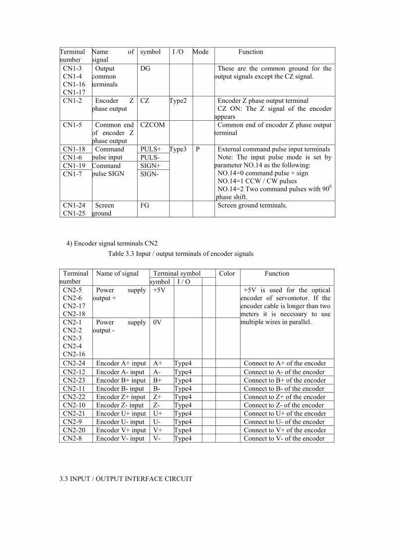
Table 3.2 Control signal input / output terminals CN1 (continue)
Terminal number
Name of signal
symbol I /O Mode Function
CN1-3 CN1-4 CN1-16 CN1-17
Output common terminals
DG These are the common ground for the output signals except the CZ signal.
CN1-2 Encoder Z phase output
CZ Type2 Encoder Z phase output terminal CZ ON: The Z signal of the encoder
appears CN1-5 Common end
of encoder Z phase output
CZCOM Common end of encoder Z phase output terminal
CN1-18 PULS+ CN1-6
Command pulse input PULS-
CN1-19 SIGN+ CN1-7
Command pulse SIGN SIGN-
Type3 P External command pulse input terminals Note: The input pulse mode is set by
parameter NO.14 as the following: NO.14=0 command pulse + sign NO.14=1 CCW / CW pulses NO.14=2 Two command pulses with 900
phase shift. CN1-24 CN1-25
Screen ground
FG Screen ground terminals.
4) Encoder signal terminals CN2 Table 3.3 Input / output terminals of encoder signals
Terminal symbol Terminal number
Name of signal symbol I / O
Color Function
CN2-5 CN2-6 CN2-17 CN2-18
Power supply output +
+5V
CN2-1 CN2-2 CN2-3 CN2-4 CN2-16
Power supply output -
0V
+5V is used for the optical encoder of servomotor. If the encoder cable is longer than two meters it is necessary to use multiple wires in parallel.
CN2-24 Encoder A+ input A+ Type4 Connect to A+ of the encoder CN2-12 Encoder A- input A- Type4 Connect to A- of the encoder CN2-23 Encoder B+ input B+ Type4 Connect to B+ of the encoder CN2-11 Encoder B- input B- Type4 Connect to B- of the encoder CN2-22 Encoder Z+ input Z+ Type4 Connect to Z+ of the encoder CN2-10 Encoder Z- input Z- Type4 Connect to Z- of the encoder CN2-21 Encoder U+ input U+ Type4 Connect to U+ of the encoder CN2-9 Encoder U- input U- Type4 Connect to U- of the encoder CN2-20 Encoder V+ input V+ Type4 Connect to V+ of the encoder CN2-8 Encoder V- input V- Type4 Connect to V- of the encoder
3.3 INPUT / OUTPUT INTERFACE CIRCUIT
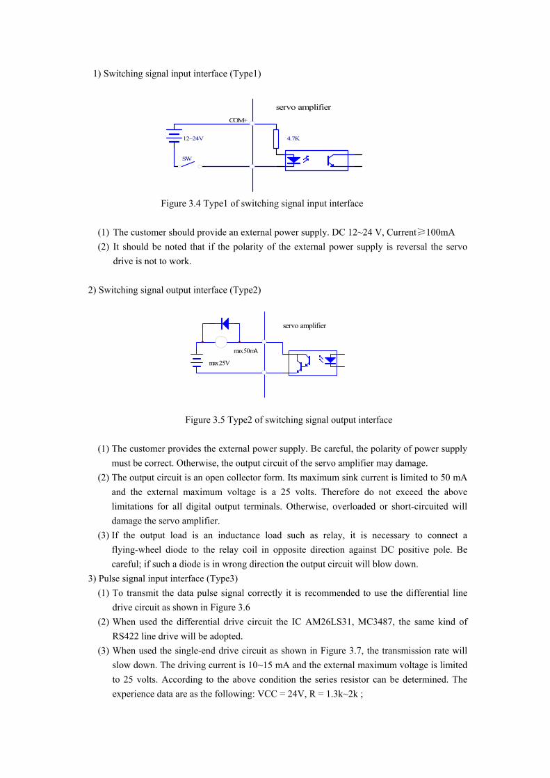
1) Switching signal input interface (Type1)
4.7K12~24V
SW
servo amplifierCOM+
Figure 3.4 Type1 of switching signal input interface
(1) The customer should provide an external power supply. DC 12~24 V, Current≥100mA (2) It should be noted that if the polarity of the external power supply is reversal the servo
drive is not to work. 2) Switching signal output interface (Type2)
servo amplifier
max 25V
max 50mA
Figure 3.5 Type2 of switching signal output interface
(1) The customer provides the external power supply. Be careful, the polarity of power supply must be correct. Otherwise, the output circuit of the servo amplifier may damage.
(2) The output circuit is an open collector form. Its maximum sink current is limited to 50 mA and the external maximum voltage is a 25 volts. Therefore do not exceed the above limitations for all digital output terminals. Otherwise, overloaded or short-circuited will damage the servo amplifier.
(3) If the output load is an inductance load such as relay, it is necessary to connect a flying-wheel diode to the relay coil in opposite direction against DC positive pole. Be careful; if such a diode is in wrong direction the output circuit will blow down.
3) Pulse signal input interface (Type3) (1) To transmit the data pulse signal correctly it is recommended to use the differential line
drive circuit as shown in Figure 3.6 (2) When used the differential drive circuit the IC AM26LS31, MC3487, the same kind of
RS422 line drive will be adopted. (3) When used the single-end drive circuit as shown in Figure 3.7, the transmission rate will
slow down. The driving current is 10~15 mA and the external maximum voltage is limited to 25 volts. According to the above condition the series resistor can be determined. The experience data are as the following: VCC = 24V, R = 1.3k~2k ;
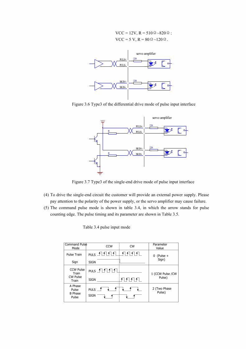
VCC = 12V, R = 510Ω~820Ω; VCC = 5 V, R = 80Ω~120Ω.
220
220
servo amplifierPULS+
PULS-
SIGN+
SIGN-
Figure 3.6 Type3 of the differential drive mode of pulse input interface
220
220
servo amplifier
PULS+
PULS-
SIGN+
SIGN-
R
R
VCC
Figure 3.7 Type3 of the single-end drive mode of pulse input interface
(4) To drive the single-end circuit the customer will provide an external power supply. Please pay attention to the polarity of the power supply, or the servo amplifier may cause failure.
(5) The command pulse mode is shown in table 3.4, in which the arrow stands for pulse counting edge. The pulse timing and its parameter are shown in Table 3.5.
Table 3.4 pulse input mode
Command PulseMode
CCW PulseTrain
CW PulseTrain
PULS
SIGN
PULS
PULS
SIGN
SIGN
A PhasePulse
B PhasePulse
Pulse Train
Sign
CCW CW ParameterValue
0 (Pulse +Sign)
1 (CCW Pulse /CWPulse)
2 (Two PhasePulse)
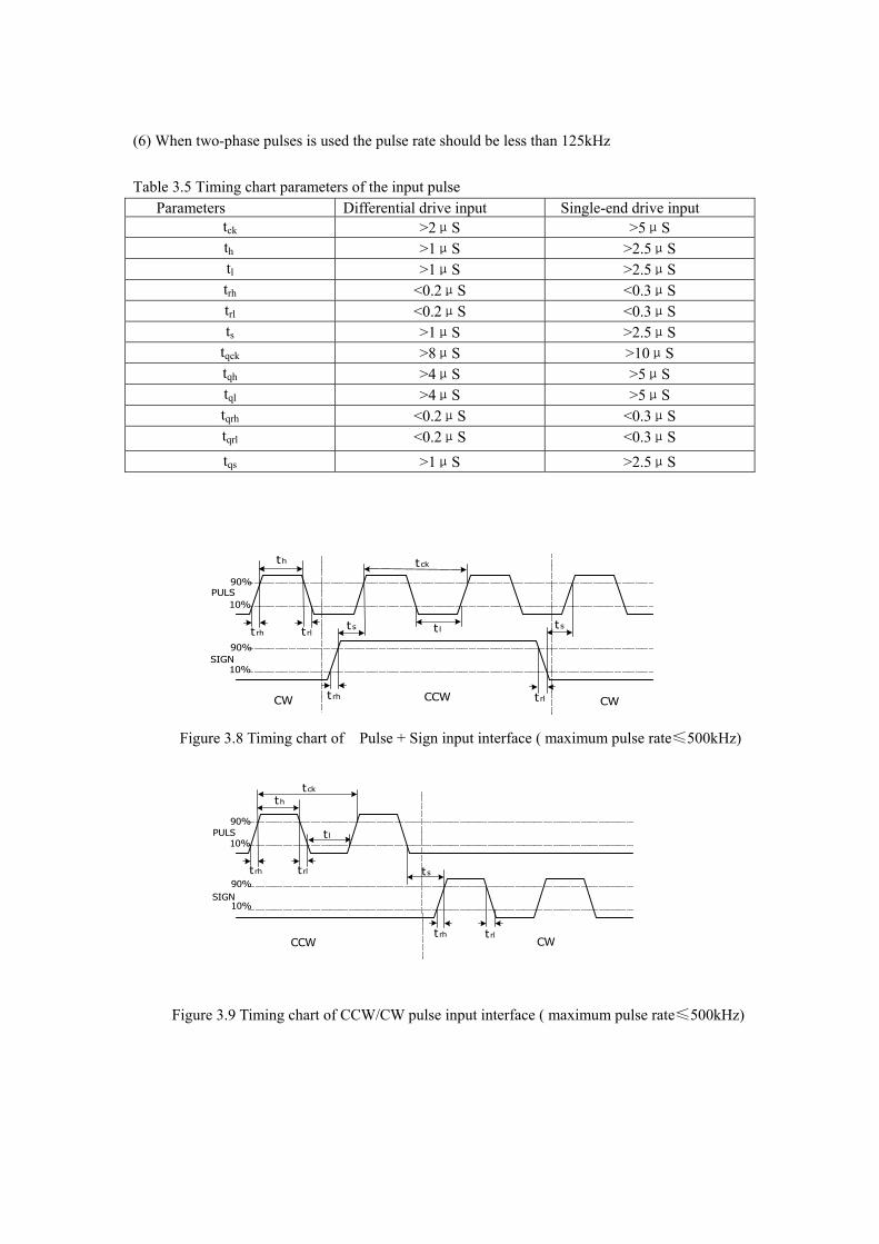
(6) When two-phase pulses is used the pulse rate should be less than 125kHz Table 3.5 Timing chart parameters of the input pulse Parameters Differential drive input Single-end drive input
tck >2μS >5μS th >1μS >2.5μS tl >1μS >2.5μS trh <0.2μS <0.3μS trl <0.2μS <0.3μS ts >1μS >2.5μS
tqck >8μS >10μS tqh >4μS >5μS tql >4μS >5μS tqrh <0.2μS <0.3μS tqrl <0.2μS <0.3μS tqs >1μS >2.5μS
t h
t lt rh t rlt s t s
t ck
t rh t rl
90%
90%
10%
10%
CW CWCCW
PULS
SIGN
Figure 3.8 Timing chart of Pulse + Sign input interface ( maximum pulse rate≤500kHz)
t h
t l
t rh t rl t s
t ck
t rh t rl
10%
10%
90%
90%
CCW CW
PULS
SIGN
Figure 3.9 Timing chart of CCW/CW pulse input interface ( maximum pulse rate≤500kHz)
t qh
t ql
t qrh t qrl
t qck
10%
10%
90%
90%
tqs t qs
t qrht qrl
CCW CW
PULS
SIGN
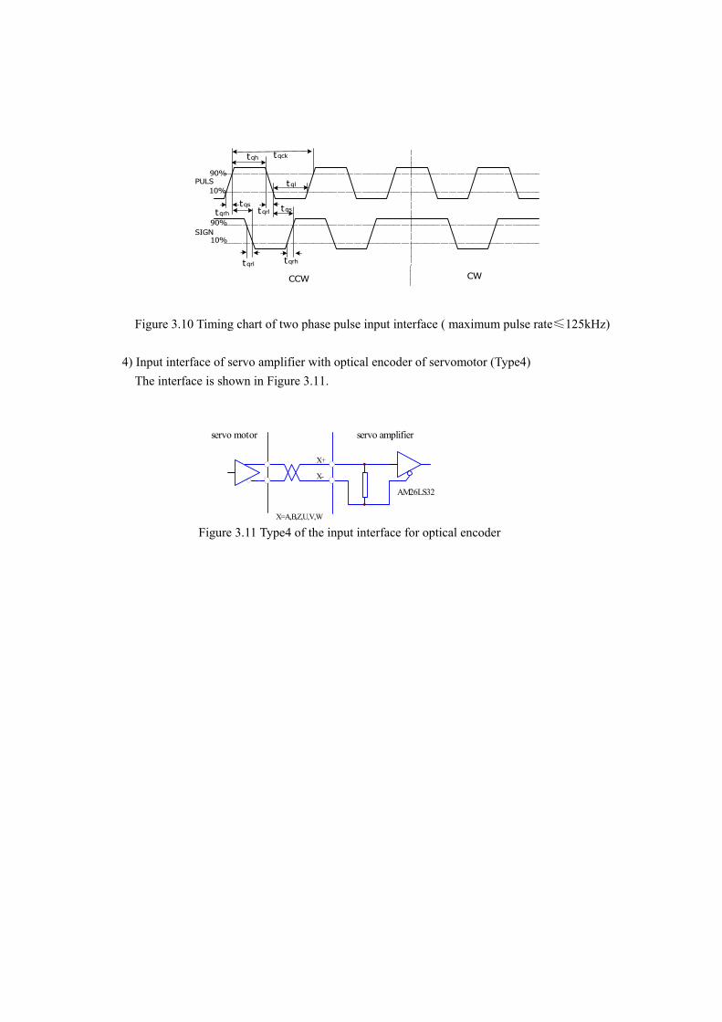
Figure 3.10 Timing chart of two phase pulse input interface ( maximum pulse rate≤125kHz) 4) Input interface of servo amplifier with optical encoder of servomotor (Type4) The interface is shown in Figure 3.11.
servo amplifierservo motor
X+
X-
X=A,B,Z,U,V,W
AM26LS32
Figure 3.11 Type4 of the input interface for optical encoder
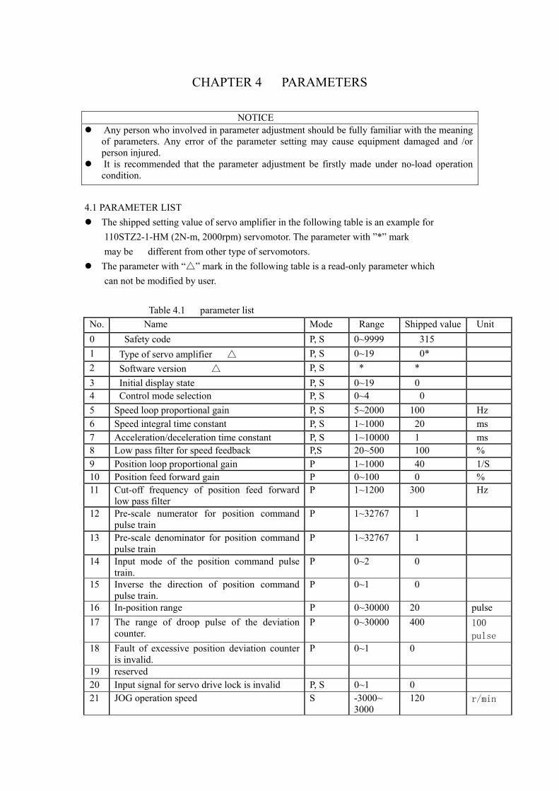
CHAPTER 4 PARAMETERS NOTICE
Any person who involved in parameter adjustment should be fully familiar with the meaning of parameters. Any error of the parameter setting may cause equipment damaged and /or person injured.
It is recommended that the parameter adjustment be firstly made under no-load operation condition.
4.1 PARAMETER LIST
The shipped setting value of servo amplifier in the following table is an example for 110STZ2-1-HM (2N-m, 2000rpm) servomotor. The parameter with ”*” mark may be different from other type of servomotors.
The parameter with “△” mark in the following table is a read-only parameter which can not be modified by user. Table 4.1 parameter list No. Name Mode Range Shipped value Unit 0 Safety code P, S 0~9999 315 1 Type of servo amplifier △ P, S 0~19 0* 2 Software version △ P, S * * 3 Initial display state P, S 0~19 0 4 Control mode selection P, S 0~4 0 5 Speed loop proportional gain P, S 5~2000 100 Hz 6 Speed integral time constant P, S 1~1000 20 ms 7 Acceleration/deceleration time constant P, S 1~10000 1 ms 8 Low pass filter for speed feedback P,S 20~500 100 % 9 Position loop proportional gain P 1~1000 40 1/S 10 Position feed forward gain P 0~100 0 % 11 Cut-off frequency of position feed forward
low pass filter P 1~1200 300 Hz
12 Pre-scale numerator for position command pulse train
P 1~32767 1
13 Pre-scale denominator for position command pulse train
P 1~32767 1
14 Input mode of the position command pulse train.
P 0~2 0
15 Inverse the direction of position command pulse train.
P 0~1 0
16 In-position range P 0~30000 20 pulse 17 The range of droop pulse of the deviation
counter. P 0~30000 400 100
pulse 18 Fault of excessive position deviation counter
is invalid. P 0~1 0
19 reserved
20 Input signal for servo drive lock is invalid P, S 0~1 0
21 JOG operation speed S -3000~ 3000
120 r/min
22 reserved
No.
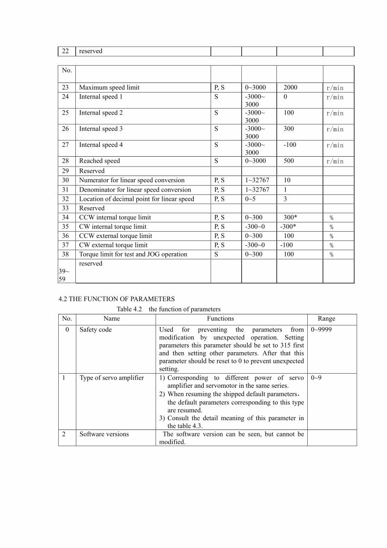
23 Maximum speed limit P, S 0~3000 2000 r/min
24 Internal speed 1 S -3000~ 3000
0 r/min
25 Internal speed 2 S -3000~ 3000
100 r/min
26 Internal speed 3 S -3000~ 3000
300 r/min
27 Internal speed 4 S -3000~ 3000
-100 r/min
28 Reached speed S 0~3000 500 r/min
29 Reserved
30 Numerator for linear speed conversion P, S 1~32767 10
31 Denominator for linear speed conversion P, S 1~32767 1
32 Location of decimal point for linear speed P, S 0~5 3
33 Reserved
34 CCW internal torque limit P, S 0~300 300* %
35 CW internal torque limit P, S -300~0 -300* %
36 CCW external torque limit P, S 0~300 100 %
37 CW external torque limit P, S -300~0 -100 %
38 Torque limit for test and JOG operation S 0~300 100 %
39~59
reserved
4.2 THE FUNCTION OF PARAMETERS Table 4.2 the function of parameters
No. Name Functions Range 0 Safety code Used for preventing the parameters from
modification by unexpected operation. Setting parameters this parameter should be set to 315 first and then setting other parameters. After that this parameter should be reset to 0 to prevent unexpected setting.
0~9999
1 Type of servo amplifier 1) Corresponding to different power of servo amplifier and servomotor in the same series.
2) When resuming the shipped default parameters, the default parameters corresponding to this type are resumed.
3) Consult the detail meaning of this parameter in the table 4.3.
0~9
2 Software versions The software version can be seen, but cannot be modified.
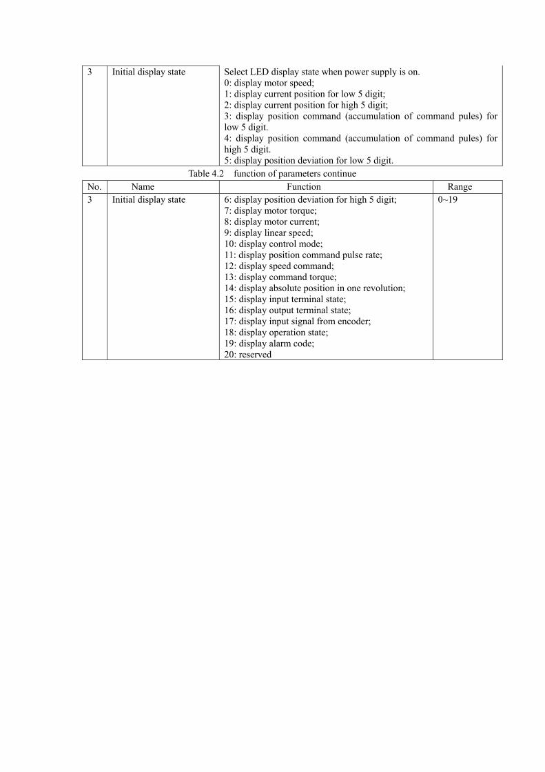
3 Initial display state Select LED display state when power supply is on. 0: display motor speed; 1: display current position for low 5 digit; 2: display current position for high 5 digit; 3: display position command (accumulation of command pules) for low 5 digit. 4: display position command (accumulation of command pules) for high 5 digit. 5: display position deviation for low 5 digit.
Table 4.2 function of parameters continue No. Name Function Range 3 Initial display state 6: display position deviation for high 5 digit;
7: display motor torque; 8: display motor current; 9: display linear speed; 10: display control mode; 11: display position command pulse rate; 12: display speed command; 13: display command torque; 14: display absolute position in one revolution; 15: display input terminal state; 16: display output terminal state; 17: display input signal from encoder; 18: display operation state; 19: display alarm code; 20: reserved
0~19
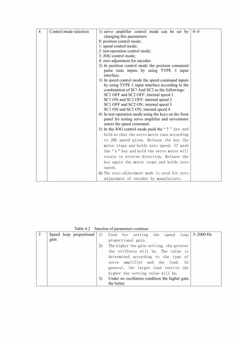
4 Control mode selection 1) servo amplifier control mode can be set by changing this parameters:
0: position control mode; 1: speed control mode; 2: test-operation control mode; 3: JOG control mode; 4: zero adjustment for encoder. 2) In position control mode the position commend
pulse train inputs by using TYPE 3 input interface.
3) In speed control mode the speed command inputs by using TYPE 1 input interface according to the combination of SC! And SC2 as the followings: SC1 OFF and SC2 OFF: internal speed 1 SC1 ON and SC2 OFF: internal speed 2 SC1 OFF and SC2 ON: internal speed 3 SC1 ON and SC2 ON: internal speed 4
4) In test-operation mode using the keys on the front panel for testing servo amplifier and servomotor enters the speed command.
5) In the JOG control mode push the “↑” key and hold so that the servo motor runs according
to JOG speed given. Release the key the
motor stops and holds zero speed. If push
the “↓” key and hold the servo motor will
rotate in reverse direction. Release the
key again the motor stops and holds zero
speed. 6) The zero adjustment mode is used for zero
adjustment of encoder by manufacture.
0~4
Table 4.2 function of parameters continue
5 Speed loop proportional gain
1) Used for setting the speed loop
proportional gain.
2) The higher the gain setting, the greater
the stiffness will be. The value is
determined according to the type of
servo amplifier and the load. In
general, the larger load inertia the
higher the setting value will be. 3) Under no oscillation condition the higher gain
the better.
5~2000 Hz
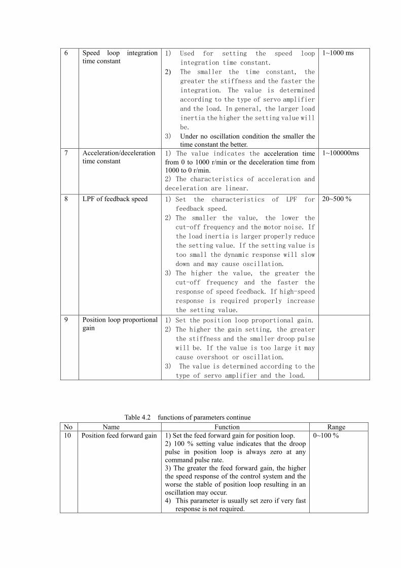
6 Speed loop integration time constant
1) Used for setting the speed loop
integration time constant.
2) The smaller the time constant, the
greater the stiffness and the faster the
integration. The value is determined
according to the type of servo amplifier
and the load. In general, the larger load
inertia the higher the setting value will
be. 3) Under no oscillation condition the smaller the
time constant the better.
1~1000 ms
7 Acceleration/deceleration time constant
1) The value indicates the acceleration time from 0 to 1000 r/min or the deceleration time from 1000 to 0 r/min. 2) The characteristics of acceleration and
deceleration are linear.
1~100000ms
8 LPF of feedback speed 1) Set the characteristics of LPF for
feedback speed.
2) The smaller the value, the lower the
cut-off frequency and the motor noise. If
the load inertia is larger properly reduce
the setting value. If the setting value is
too small the dynamic response will slow
down and may cause oscillation.
3) The higher the value, the greater the cut-off frequency and the faster the
response of speed feedback. If high-speed
response is required properly increase
the setting value.
20~500 %
9 Position loop proportional gain
1) Set the position loop proportional gain. 2) The higher the gain setting, the greater
the stiffness and the smaller droop pulse
will be. If the value is too large it may
cause overshoot or oscillation.
3) The value is determined according to the
type of servo amplifier and the load.
Table 4.2 functions of parameters continue No Name Function Range 10 Position feed forward gain 1) Set the feed forward gain for position loop.
2) 100 % setting value indicates that the droop pulse in position loop is always zero at any command pulse rate. 3) The greater the feed forward gain, the higher the speed response of the control system and the worse the stable of position loop resulting in an oscillation may occur. 4) This parameter is usually set zero if very fast
response is not required.
0~100 %
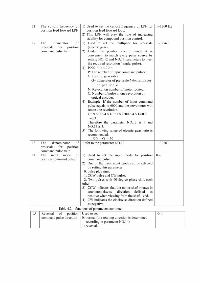
11 The cut-off frequency of position feed forward LPF
1) Used to set the cut-off frequency of LPF for position feed forward loop.
2) This LPF will play the role of increasing stability for compound position control.
1~1200 Hz
12 The numerator of pre-scale for position command pulse train
1) Used to set the multiplier for pre-scale (electric gear).
2) Under the position control mode it is convenient to match every pulse source by setting NO.12 and NO.13 parameters to meet the required resolution ( angle/ pulse).
3) P×G = N×C×4 P: The number of input command pulses; G: Electric gear ratio; G= numerator of pre-scale÷denominator
of pre-scale. N: Revolution number of motor rotated. C: Number of pulse in one revolution of optical encoder.
4) Example: If the number of input command pulse equals to 6000 and the servomotor will rotate one revolution. G=N×C×4×1/P=1×2500×4×1/6000 =5/3 Therefore the parameter NO.12 is 5 and NO.13 is 3.
5) The following range of electric gear ratio is recommended.
1/50<= G =<50
1~32767
13 The denominator of pre-scale for position command pulse train
Refer to the parameter NO.12. 1~32767
14 The input mode of position command pulse
1) Used to set the input mode for position command pulse.
2) One of the three input mode can be selected by setting this parameter:
0: pulse plus sign; 1: CCW pulse and CW pulse; 2: Two pulses with 90 degree phase shift each other 3) CCW indicates that the motor shaft rotates in
counterclockwise direction defined as positive when viewing from the shaft –end.
4) CW indicates the clockwise direction defined as negative.
0~2
Table 4.2 functions of parameters continue 15 Reversal of position
command pulse direction Used to set 0: normal (the rotating direction is determined according to parameter NO.14) 1: reversal.
0~1
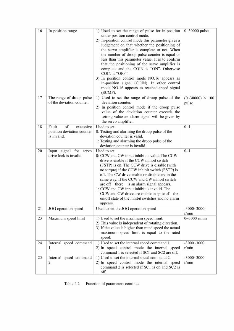
16 In-position range 1) Used to set the range of pulse for in-position under position control mode.
2) In-position control mode this parameter gives a judgement on that whether the positioning of the servo amplifier is complete or not. When the number of droop pulse counter is equal or less than this parameter value. It is to confirm that the positioning of the servo amplifier is complete and the COIN is “ON”. Otherwise COIN is “OFF”.
3) In position control mode NO.16 appears as in-position signal (COIN). In other control mode NO.16 appears as reached-speed signal (SCMP).
0~30000 pulse
17 The range of droop pulse of the deviation counter.
1) Used to set the range of droop pulse of the deviation counter.
2) In position control mode if the droop pulse value of the deviation counter exceeds the setting value an alarm signal will be given by the servo amplifier.
(0~30000) × 100 pulse
18 Fault of excessive position deviation counter is invalid.
Used to set 0: Testing and alarming the droop pulse of the deviation counter is valid. 1: Testing and alarming the droop pulse of the deviation counter is invalid.
0~1
20 Input signal for servo drive lock is invalid
Used to set 0: CCW and CW input inhibit is valid. The CCW drive is enable if the CCW inhibit switch (FSTP) is on. The CCW drive is disable (with no torque) if the CCW inhibit switch (FSTP) is off. The CW drive enable or disable are in the same way. If the CCW and CW inhibit switch are off there is an alarm signal appears. 1: CCW and CW input inhibit is invalid. The CCW and CW drive are enable in spite of the on/off state of the inhibit switches and no alarm appears.
0~1
21 JOG operation speed Used to set the JOG operation speed -3000~3000 r/min
23 Maximum speed limit 1) Used to set the maximum speed limit. 2) This value is independent of rotating direction. 3) If the value is higher than rated speed the actual
maximum speed limit is equal to the rated speed.
0~3000 r/min
24 Internal speed command 1
1) Used to set the internal speed command 1. 2) In speed control mode the internal speed
command 1 is selected if SC1 and SC2 are off.
-3000~3000 r/min
25 Internal speed command 2
1) Used to set the internal speed command 2. 2) In speed control mode the internal speed
command 2 is selected if SC1 is on and SC2 is off.
-3000~3000 r/min
Table 4.2 Function of parameters continue
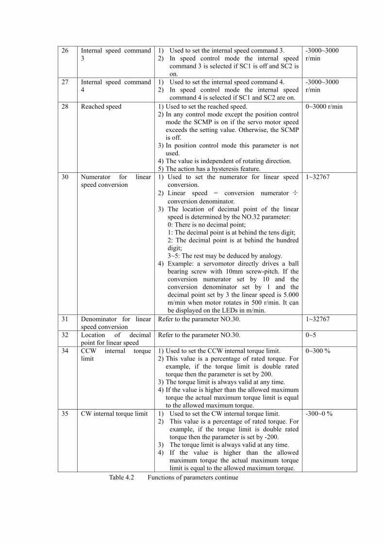
26 Internal speed command 3
1) Used to set the internal speed command 3. 2) In speed control mode the internal speed
command 3 is selected if SC1 is off and SC2 is on.
-3000~3000 r/min
27 Internal speed command 4
1) Used to set the internal speed command 4. 2) In speed control mode the internal speed
command 4 is selected if SC1 and SC2 are on.
-3000~3000 r/min
28 Reached speed 1) Used to set the reached speed. 2) In any control mode except the position control
mode the SCMP is on if the servo motor speed exceeds the setting value. Otherwise, the SCMP is off.
3) In position control mode this parameter is not used.
4) The value is independent of rotating direction. 5) The action has a hysteresis feature.
0~3000 r/min
30 Numerator for linear speed conversion
1) Used to set the numerator for linear speed conversion.
2) Linear speed = conversion numerator ÷conversion denominator.
3) The location of decimal point of the linear speed is determined by the NO.32 parameter: 0: There is no decimal point; 1: The decimal point is at behind the tens digit; 2: The decimal point is at behind the hundred digit; 3~5: The rest may be deduced by analogy.
4) Example: a servomotor directly drives a ball bearing screw with 10mm screw-pitch. If the conversion numerator set by 10 and the conversion denominator set by 1 and the decimal point set by 3 the linear speed is 5.000 m/min when motor rotates in 500 r/min. It can be displayed on the LEDs in m/min.
1~32767
31 Denominator for linear speed conversion
Refer to the parameter NO.30. 1~32767
32 Location of decimal point for linear speed
Refer to the parameter NO.30. 0~5
34 CCW internal torque limit
1) Used to set the CCW internal torque limit. 2) This value is a percentage of rated torque. For
example, if the torque limit is double rated torque then the parameter is set by 200.
3) The torque limit is always valid at any time. 4) If the value is higher than the allowed maximum
torque the actual maximum torque limit is equal to the allowed maximum torque.
0~300 %
35 CW internal torque limit 1) Used to set the CW internal torque limit. 2) This value is a percentage of rated torque. For
example, if the torque limit is double rated torque then the parameter is set by -200.
3) The torque limit is always valid at any time. 4) If the value is higher than the allowed
maximum torque the actual maximum torque limit is equal to the allowed maximum torque.
-300~0 %
Table 4.2 Functions of parameters continue
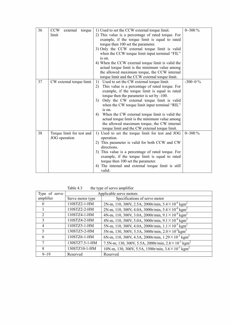
36 CCW external torque limit
1) Used to set the CCW external torque limit. 2) This value is a percentage of rated torque. For
example, if the torque limit is equal to rated torque then 100 set the parameter.
3) Only the CCW external torque limit is valid when the CCW torque limit input terminal “FIL” is on.
4) When the CCW external torque limit is valid the actual torque limit is the minimum value among the allowed maximum torque, the CCW internal torque limit and the CCW external torque limit.
0~300 %
37 CW external torque limit 1) Used to set the CW external torque limit. 2) This value is a percentage of rated torque. For
example, if the torque limit is equal to rated torque then the parameter is set by -100.
3) Only the CW external torque limit is valid when the CW torque limit input terminal “RIL” is on.
4) When the CW external torque limit is valid the actual torque limit is the minimum value among the allowed maximum torque, the CW internal torque limit and the CW external torque limit.
-300~0 %
38 Torque limit for test and JOG operation
1) Used to set the torque limit for test and JOG operation.
2) This parameter is valid for both CCW and CW directions.
3) This value is a percentage of rated torque. For example, if the torque limit is equal to rated torque then 100 set the parameter.
4) The internal and external torque limit is still valid.
0~300 %
Table 4.3 the type of servo amplifier
Applicable serve motors Type of servo amplifier Serve motor type Specifications of servo motor 0 110STZ2-1-HM 2N-m, 110, 300V, 2.5A, 2000r/min, 5.4×10⁻⁴ kgm2
1 110STZ2-2-HM 2N-m, 110, 300V, 4.0A, 3000r/min, 5.4×10⁻⁴ kgm2
2 110STZ4-1-HM 4N-m, 110, 300V, 3.0A, 2000r/min, 9.1×10⁻⁴ kgm2
3 110STZ4-2-HM 4N-m, 110, 300V, 5.0A, 3000r/min, 9.1×10⁻⁴ kgm2
4 110STZ5-1-HM 5N-m, 110, 300V, 4.0A, 2000r/min, 1.1×10⁻³ kgm2
5 130STZ5-2-HM 5N-m, 130, 300V, 5.5A, 3000r/min, 2.0×10⁻³kgm2
6 110STZ6-1-HM 6N-m, 110, 300V, 4.5A, 2000r/min, 1.29×10⁻³ kgm2
7 130STZ7.5-1-HM 7.5N-m, 130, 300V, 5.5A, 2000r/min, 2.8×10⁻³ kgm2
8 130STZ10-1-HM 10N-m, 130, 300V, 5.5A, 1500r/min, 3.6×10⁻³ kgm2
9~19 Reserved Reserved
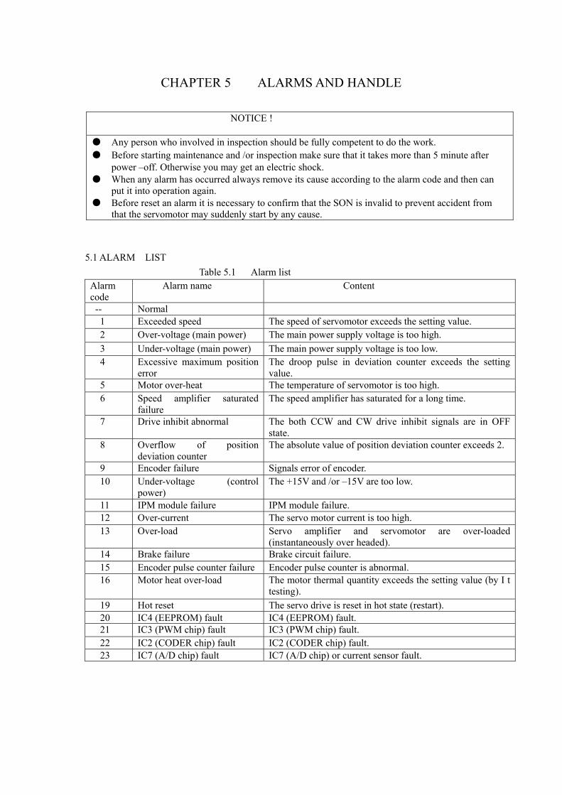
CHAPTER 5 ALARMS AND HANDLE
NOTICE ! ● Any person who involved in inspection should be fully competent to do the work. ● Before starting maintenance and /or inspection make sure that it takes more than 5 minute after power –off. Otherwise you may get an electric shock. ● When any alarm has occurred always remove its cause according to the alarm code and then can put it into operation again. ● Before reset an alarm it is necessary to confirm that the SON is invalid to prevent accident from that the servomotor may suddenly start by any cause.
5.1 ALARM LIST Table 5.1 Alarm list
Alarm code
Alarm name Content
-- Normal 1 Exceeded speed The speed of servomotor exceeds the setting value. 2 Over-voltage (main power) The main power supply voltage is too high. 3 Under-voltage (main power) The main power supply voltage is too low. 4 Excessive maximum position
error The droop pulse in deviation counter exceeds the setting value.
5 Motor over-heat The temperature of servomotor is too high. 6 Speed amplifier saturated
failure The speed amplifier has saturated for a long time.
7 Drive inhibit abnormal The both CCW and CW drive inhibit signals are in OFF state.
8 Overflow of position deviation counter
The absolute value of position deviation counter exceeds 2.
9 Encoder failure Signals error of encoder. 10 Under-voltage (control
power) The +15V and /or –15V are too low.
11 IPM module failure IPM module failure. 12 Over-current The servo motor current is too high. 13 Over-load Servo amplifier and servomotor are over-loaded
(instantaneously over headed). 14 Brake failure Brake circuit failure. 15 Encoder pulse counter failure Encoder pulse counter is abnormal. 16 Motor heat over-load The motor thermal quantity exceeds the setting value (by I t
testing). 19 Hot reset The servo drive is reset in hot state (restart). 20 IC4 (EEPROM) fault IC4 (EEPROM) fault. 21 IC3 (PWM chip) fault IC3 (PWM chip) fault. 22 IC2 (CODER chip) fault IC2 (CODER chip) fault. 23 IC7 (A/D chip) fault IC7 (A/D chip) or current sensor fault.
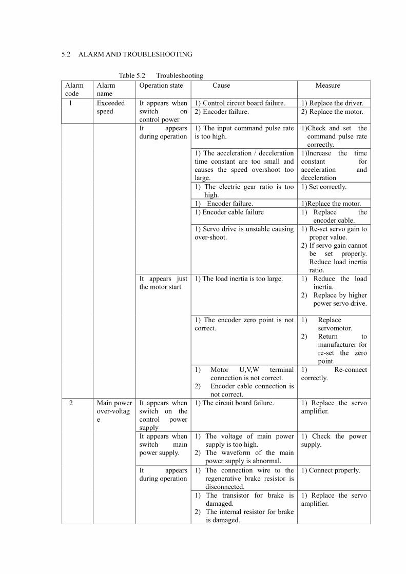
5.2 ALARM AND TROUBLESHOOTING Table 5.2 Troubleshooting
Alarm code
Alarm name
Operation state Cause Measure
1) Control circuit board failure. 1) Replace the driver. 1 Exceeded speed
It appears when switch on control power
2) Encoder failure. 2) Replace the motor.
1) The input command pulse rate is too high.
1) Check and set the command pulse rate correctly.
1) The acceleration / deceleration time constant are too small and causes the speed overshoot too large.
1)Increase the time constant for acceleration and deceleration
1) The electric gear ratio is too high.
1) Set correctly.
1) Encoder failure. 1)Replace the motor. 1) Encoder cable failure 1) Replace the
encoder cable.
It appears during operation
1) Servo drive is unstable causing over-shoot.
1) Re-set servo gain to proper value.
2) If servo gain cannot be set properly. Reduce load inertia ratio.
1) The load inertia is too large. 1) Reduce the load inertia.
2) Replace by higher power servo drive.
1) The encoder zero point is not correct.
1) Replace servomotor.
2) Return to manufacturer for re-set the zero point.
It appears just the motor start
1) Motor U,V,W terminal connection is not correct.
2) Encoder cable connection is not correct.
1) Re-connect correctly.
It appears when switch on the control power supply
1) The circuit board failure. 1) Replace the servo amplifier.
It appears when switch main power supply.
1) The voltage of main power supply is too high.
2) The waveform of the main power supply is abnormal.
1) Check the power supply.
1) The connection wire to the regenerative brake resistor is disconnected.
1) Connect properly.
2 Main power over-voltage
It appears during operation
1) The transistor for brake is damaged.
2) The internal resistor for brake is damaged.
1) Replace the servo amplifier.
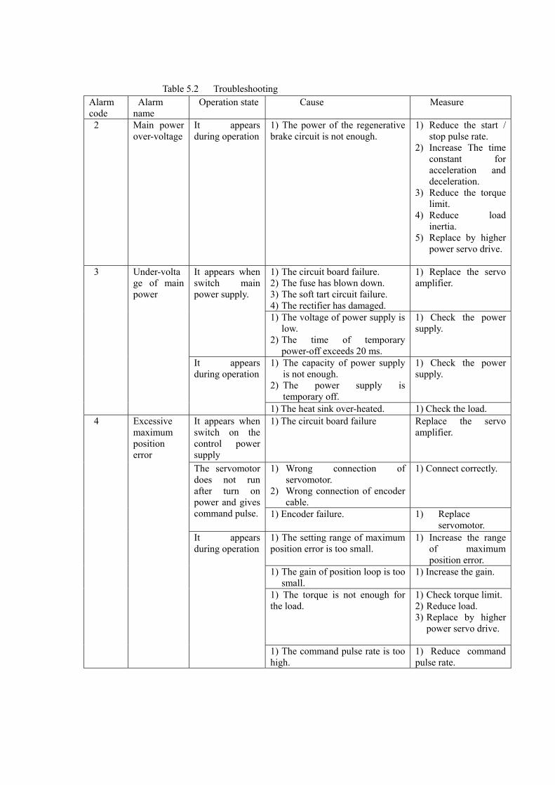
Table 5.2 Troubleshooting
Alarm code
Alarm name
Operation state Cause Measure
2 Main power over-voltage
It appears during operation
1) The power of the regenerative brake circuit is not enough.
1) Reduce the start / stop pulse rate.
2) Increase The time constant for acceleration and deceleration.
3) Reduce the torque limit.
4) Reduce load inertia.
5) Replace by higher power servo drive.
1) The circuit board failure. 2) The fuse has blown down. 3) The soft tart circuit failure. 4) The rectifier has damaged.
1) Replace the servo amplifier.
It appears when switch main power supply.
1) The voltage of power supply is low.
2) The time of temporary power-off exceeds 20 ms.
1) Check the power supply.
1) The capacity of power supply is not enough.
2) The power supply is temporary off.
1) Check the power supply.
3 Under-voltage of main power
It appears during operation
1) The heat sink over-heated. 1) Check the load. It appears when switch on the control power supply
1) The circuit board failure Replace the servo amplifier.
1) Wrong connection of servomotor.
2) Wrong connection of encoder cable.
1) Connect correctly. The servomotor does not run after turn on power and gives command pulse. 1) Encoder failure. 1) Replace
servomotor. 1) The setting range of maximum position error is too small.
1) Increase the range of maximum position error.
1) The gain of position loop is too small.
1) Increase the gain.
1) The torque is not enough for the load.
1) Check torque limit. 2) Reduce load. 3) Replace by higher
power servo drive.
4 Excessive maximum position error
It appears during operation
1) The command pulse rate is too high.
1) Reduce command pulse rate.
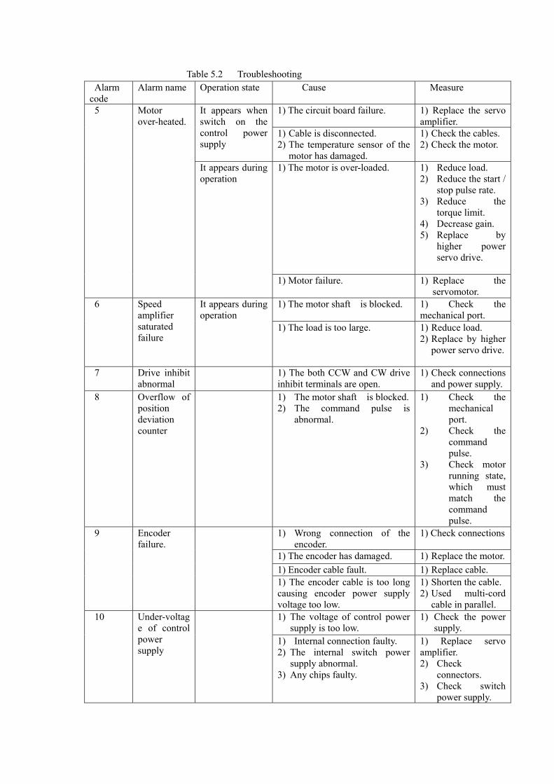
Table 5.2 Troubleshooting Alarm code
Alarm name
Operation state Cause Measure
1) The circuit board failure. 1) Replace the servo amplifier.
It appears when switch on the control power supply
1) Cable is disconnected. 2) The temperature sensor of the
motor has damaged.
1) Check the cables. 2) Check the motor.
1) The motor is over-loaded. 1) Reduce load. 2) Reduce the start /
stop pulse rate. 3) Reduce the
torque limit. 4) Decrease gain. 5) Replace by
higher power servo drive.
5 Motor over-heated.
It appears during operation
1) Motor failure. 1) Replace the servomotor.
1) The motor shaft is blocked. 1) Check the mechanical port.
6 Speed amplifier saturated failure
It appears during operation
1) The load is too large. 1) Reduce load. 2) Replace by higher
power servo drive.
7 Drive inhibit abnormal
1) The both CCW and CW drive inhibit terminals are open.
1) Check connections and power supply.
8 Overflow of position deviation counter
1) The motor shaft is blocked. 2) The command pulse is
abnormal.
1) Check the mechanical port.
2) Check the command pulse.
3) Check motor running state, which must match the command pulse.
1) Wrong connection of the encoder.
1) Check connections
1) The encoder has damaged. 1) Replace the motor. 1) Encoder cable fault. 1) Replace cable.
9 Encoder failure.
1) The encoder cable is too long causing encoder power supply voltage too low.
1) Shorten the cable. 2) Used multi-cord
cable in parallel. 1) The voltage of control power
supply is too low. 1) Check the power
supply. 10 Under-voltag
e of control power supply
1) Internal connection faulty. 2) The internal switch power
supply abnormal. 3) Any chips faulty.
1) Replace servo amplifier. 2) Check
connectors. 3) Check switch
power supply.
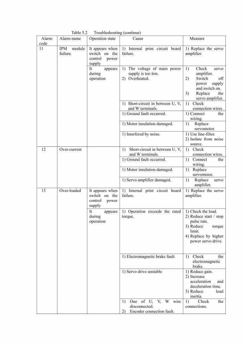
Table 5.2 Troubleshooting (continue) Alarm code
Alarm name
Operation state Cause Measure
It appears when switch on the control power supply
1) Internal print circuit board failure.
1) Replace the servo amplifier.
1) The voltage of main power supply is too low.
2) Overheated.
1) Check servo amplifier.
2) Switch off power supply and switch on.
3) Replace the servo amplifier.
1) Short-circuit in between U, V, and W terminals.
1) Check connection wires.
1) Ground fault occurred. 1) Connect the wiring.
1) Motor insulation damaged. 1) Replace servomotor.
11 IPM module failure.
It appears during operation
1) Interfered by noise. 1) Use line-filter. 2) Isolate from noise
source. 1) Short-circuit in between U, V,
and W terminals. 1) Check
connection wires. 1) Ground fault occurred. 1) Connect the
wiring. 1) Motor insulation damaged. 1) Replace
servomotor.
12 Over-current
1) Servo amplifier damaged. 1) Replace servo amplifier.
It appears when switch on the control power supply
1) Internal print circuit board failure.
1) Replace the servo amplifier.
1) Operation exceeds the rated torque.
1) Check the load. 2) Reduce start / stop
pulse rate. 3) Reduce torque
limit. 4) Replace by higher
power servo drive.
1) Electromagnetic brake fault. 1) Check the electromagnetic brake.
1) Servo drive unstable 1) Reduce gain. 2) Increase
acceleration and deceleration time.
3) Reduce load inertia.
13 Over-loaded
It appears during operation
1) One of U, V, W wire disconnected.
2) Encoder connection fault.
1) Check the connections.
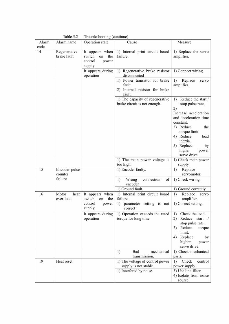
Table 5.2 Troubleshooting (continue)
Alarm code
Alarm name
Operation state Cause Measure
It appears when switch on the control power supply
1) Internal print circuit board failure.
1) Replace the servo amplifier.
1) Regenerative brake resistor disconnected
1) Connect wiring.
1) Power transistor for brake fault.
2) Internal resistor for brake fault.
1) Replace servo amplifier.
1) The capacity of regenerative brake circuit is not enough.
1) Reduce the start / stop pulse rate.
2) Increase acceleration and deceleration time constant. 3) Reduce the
torque limit. 4) Reduce load
inertia. 5) Replace by
higher power servo drive.
14 Regenerative brake fault
It appears during operation
1) The main power voltage is too high.
1) Check main power supply.
1) Encoder faulty. 1) Replace servomotor.
1) Wrong connection of encoder.
1) Check wiring.
15 Encoder pulse counter failure
1) Ground fault. 1) Ground correctly. 1) Internal print circuit board ailure. f
1) Replace servo amplifier.
It appears when switch on the control power supply
1) parameter setting is not correct
1) Correct setting.
1) Operation exceeds the rated torque for long time.
1) Check the load. 2) Reduce start /
stop pulse rate. 3) Reduce torque
limit. 4) Replace by
higher power servo drive.
16 Motor heat over-load
It appears during operation
1) Bad mechanical transmission.
1) Check mechanical parts.
1) The voltage of control power supply is not stable.
1) Check control power supply.
19 Heat reset
1) Interfered by noise. 3) Use line-filter. 4) Isolate from noise
source.
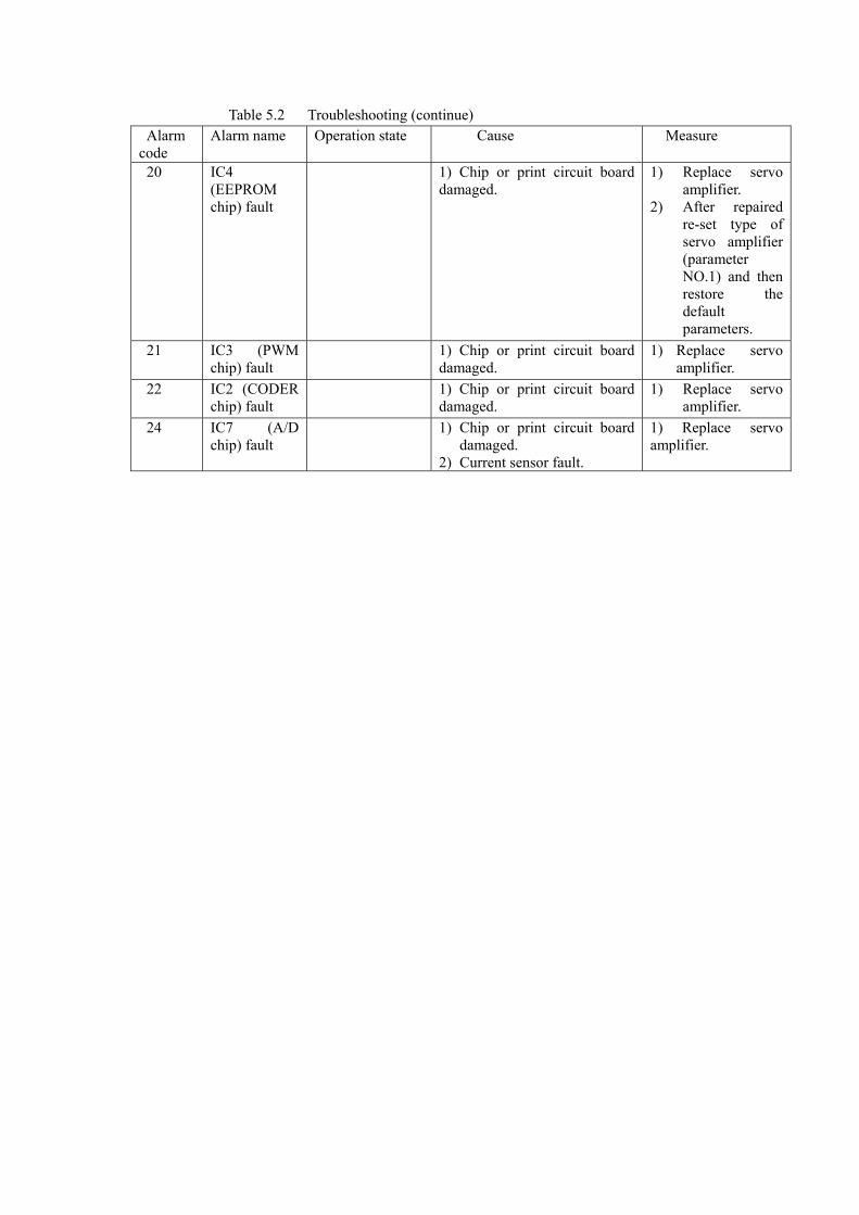
Table 5.2 Troubleshooting (continue) Alarm code
Alarm name
Operation state Cause Measure
20 IC4 (EEPROM chip) fault
1) Chip or print circuit board damaged.
1) Replace servo amplifier.
2) After repaired re-set type of servo amplifier (parameter NO.1) and then restore the default parameters.
21 IC3 (PWM chip) fault
1) Chip or print circuit board damaged.
1) Replace servo amplifier.
22 IC2 (CODER chip) fault
1) Chip or print circuit board damaged.
1) Replace servo amplifier.
24 IC7 (A/D chip) fault
1) Chip or print circuit board damaged.
2) Current sensor fault.
1) Replace servo amplifier.
CHAPTER 6. DISPLAY AND OPERATION 6.1 KEYBOARD OPERATION 1) There are 6 LED 7-Segment digit display and 4 keys (↑、↓、←、Enter) on the front panel of the servo amplifier. They are used for displaying status of servo drive
and setting parameters. The key functions are as follows:
“↑” : Sequence number, value increasing, or move forward for select item. “↓” : Sequence number, value increasing, or move backward for select item. “←” : Return to upper layer menu, or cancel the operate. “Enter” : Enter next layer menu, or input confirmed.
NOTE: If “↑” or “↓” is pressed and held the operation will repeat as that the longer the holding, the faster the execution rate.
2) The 6 LED 7-segment digit indicates the states and data of the servo drive.
All 6 digit or most right decimal point is glimmering, it indicates that alarms occur.
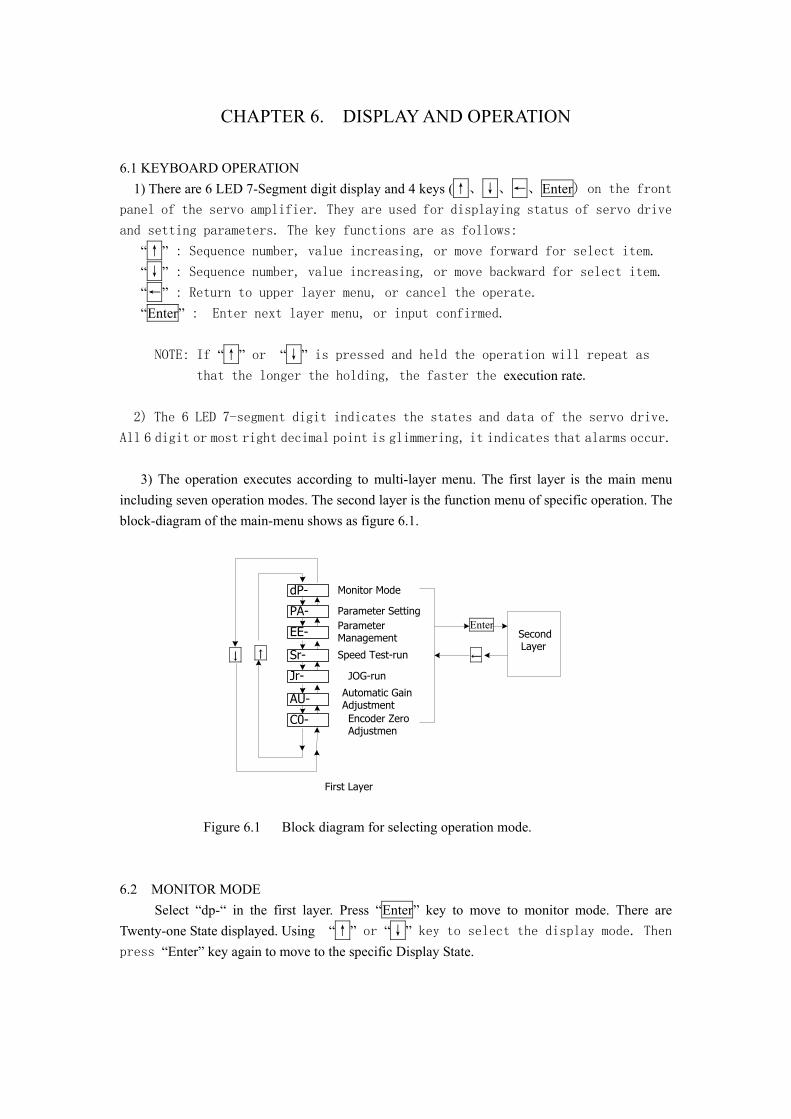
3) The operation executes according to multi-layer menu. The first layer is the main menu including seven operation modes. The second layer is the function menu of specific operation. The block-diagram of the main-menu shows as figure 6.1.
↑↓
dP-
PA-
EE-
Sr-
Jr-
AU-
C0-
Parameter SettingParameterManagement
Encoder ZeroAdjustmen
Speed Test-run
JOG-run
Automatic GainAdjustment
Monitor Mode
←
EnterSecondLayer
First Layer
Figure 6.1 Block diagram for selecting operation mode. 6.2 MONITOR MODE Select “dp-“ in the first layer. Press “Enter” key to move to monitor mode. There are Twenty-one State displayed. Using “↑” or “↓” key to select the display mode. Then press “Enter” key again to move to the specific Display State.
Enter
←
Command Position High 5 Digit(x100000 Pulse)
↑↓
Motor Speed (r/min)
Current Position Low 5 Digit(Pulse)Current Position High 5 digit(X100000 Pulse)Command Position Low 5 Digit(Pulse)
Linea Speed (m/min)
Current Control Mode
Position Deviation Low 5Digit (Pulse)
Motor Current (A)
Motor Torque (%)
Position Deviation High 5 Digit(x100000 Pulse)
Speed Command ( r/min)
Torque Command (%)
Rotor Absolute Position(Pulse)
Alarm Code
Operation Status
Signals From Encoder
Output Terminal Status
Input Terminal Status
Reserved
DP-SPd
DP-PoS.
DP-EPo
DP-CPo
DP-EPo.
DP-trq
DP-Ct
DP-I
DP-CS
DP-Cnt
DP-LSP
DP-Err
DP-rn
DP-Cod
DP-In
DP-oUt
DP-APo
DP-PoS
DP-CPo.
DP-rES
r 1000
P. 12
E 4
C45810
E. 0
t 70
t. -20
I 2.3
r. -35
Cnt 0
L 5.000
Err 9
rn- on
Cod ||||||
In||||||||
oUt ||||
A 3265
P45806
C. 12
U 0
Motor Speed 1000 r/min
Current Position 1245806Pulse
Position Command 1245810Pulse
Position Deviation 4pulse
Motor Torque 70 %
Motor Current 2.3 A
Linear Speed 5.000 m/min
Control Mode 0
Speed Command -35 r/min
Output Terminal
Rotor Absolute Position3265
Input Terminal
Torque Command -20 %
Encoder Signals
Operation Status : running
Alarm : NO: 9
DP-Frq Position Command Pulse Rate( kHz ) F 12.6 Position Command Pulse Rate
12.6kHz
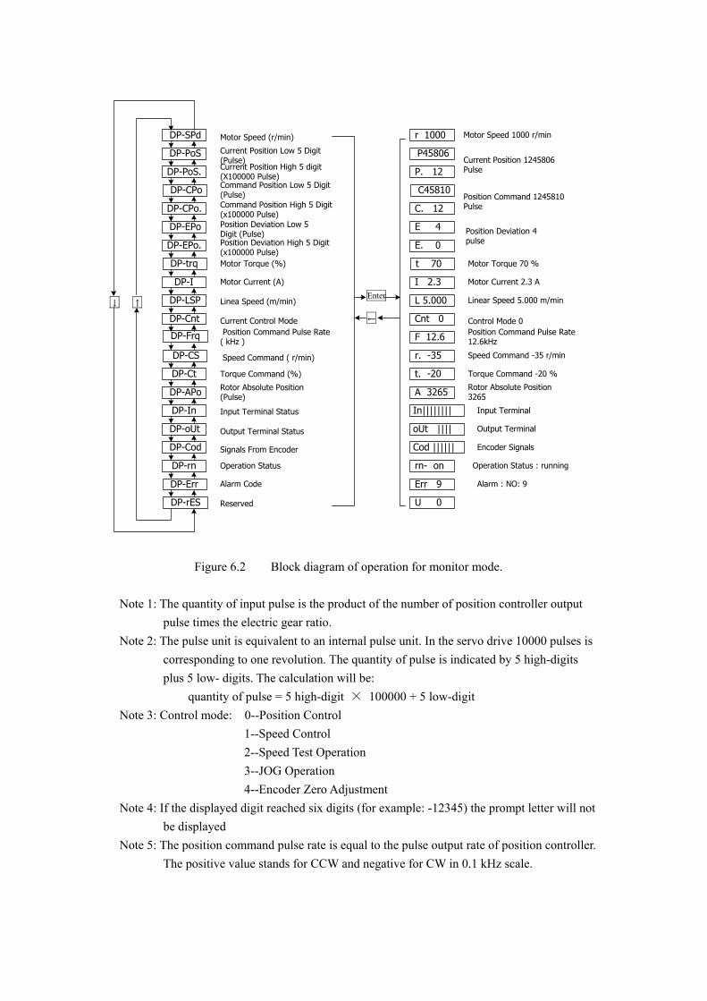
Figure 6.2 Block diagram of operation for monitor mode. Note 1: The quantity of input pulse is the product of the number of position controller output pulse times the electric gear ratio. Note 2: The pulse unit is equivalent to an internal pulse unit. In the servo drive 10000 pulses is corresponding to one revolution. The quantity of pulse is indicated by 5 high-digits plus 5 low- digits. The calculation will be: quantity of pulse = 5 high-digit × 100000 + 5 low-digit Note 3: Control mode: 0--Position Control 1--Speed Control 2--Speed Test Operation 3--JOG Operation 4--Encoder Zero Adjustment Note 4: If the displayed digit reached six digits (for example: -12345) the prompt letter will not be displayed Note 5: The position command pulse rate is equal to the pulse output rate of position controller. The positive value stands for CCW and negative for CW in 0.1 kHz scale.
Note 9: The operation status shows as: “rn- oFF” : DC-link has no voltage and servo drive is not in operation. “rn- CH” : DC-link has voltage and servo drive is not in operation ( servo enable is off or alarm is present ). “rn- on” : DC-link has voltage and servo drive is in operation. Note 9: Alarm display: “Err --“ indicates normal condition and no alarm. 6.3 PARAMETERS SETTING
NOTICE ● First, set the NO.0 parameter as 315, then other parameters can be modified. ● Soon after the parameter is set the parameter is active. Any wrong with parameters may cause the servo drive running badly or accident.
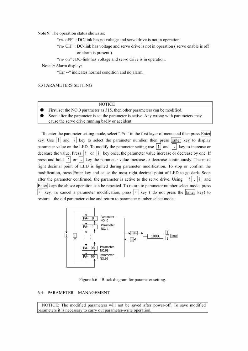
To enter the parameter setting mode, select “PA-“ in the first layer of menu and then press Enter key. Use ↑ and ↓ key to select the parameter number, then press Enter key to display parameter value on the LED. To modify the parameter setting use ↑ and ↓ key to increase or decrease the value. Press ↑ or ↓ key once, the parameter value increase or decrease by one. If press and hold ↑ or ↓ key the parameter value increase or decrease continuously. The most right decimal point of LED is lighted during parameter modification. To stop or confirm the modification, press Enter key and cause the most right decimal point of LED to go dark. Soon after the parameter confirmed, the parameter is active to the servo drive. Using ↑ , ↓ and Enter keys the above operation can be repeated. To return to parameter number select mode, press ← key. To cancel a parameter modification, press ← key ( do not press the Enter key) to restore the old parameter value and return to parameter number select mode.
PA- 0
PA- 99
PA- 1
PA- 98
: : : :
↑↓Enter
←
1000.↑
↓Enter
ParameterNO. 0
ParameterNO. 1
ParameterNO.99
ParameterNO.98
Figure 6.6 Block diagram for parameter setting. 6.4 PARAMETER MANAGEMENT
NOTICE: The modified parameters will not be saved after power-off. To save modified parameters it is necessary to carry out parameter-write operation.
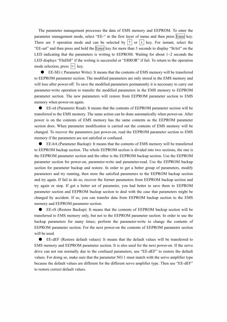
The parameter management processes the data of EMS memory and EEPROM. To enter the parameter management mode, select “EE-“ in the first layer of menu and then press Enter key. There are 5 operation mode and can be selected by ↑ or ↓ key. For instant, select the “EE-set” and then press and hold the Enter key for more than 3 seconds to display “StArt” on the LED indicating that the parameters is writing to EEPROM. Waiting for about 1~2 seconds the LED displays “FInISH” if the writing is successful or “ERROR” if fail. To return to the operation mode selection, press ← key. ● EE-SEt ( Parameter Write): It means that the contents of EMS memory will be transferred to EEPROM parameter section. The modified parameters are only stored in the EMS memory and will lose after power-off. To save the modified parameters permanently it is necessary to carry out parameter-write operation to transfer the modified parameters in the EMS memory to EEPROM parameter section. The new parameters will restore from EEPROM parameter section to EMS memory when power-on again. ● EE-rd (Parameter Read): It means that the contents of EEPROM parameter section will be transferred to the EMS memory. The same action can be done automatically when power-on. After power is on the contents of EMS memory has the same contents as the EEPROM parameter section does. When parameter modification is carried out the contents of EMS memory will be changed. To recover the parameters just power-on, read the EEPROM parameter section to EMS memory if the parameters are not satisfied or confused. ● EE-bA (Parameter Backup): It means that the contents of EMS memory will be transferred to EEPROM backup section. The whole EEPROM section is divided into two sections, the one is the EEPROM parameter section and the other is the EEPROM backup section. Use the EEPROM parameter section for power-on, parameter-write and parameter-read. Use the EEPROM backup section for parameter backup and restore. In order to get a better group of parameters, modify parameters and try running, then store the satisfied parameters to the EEPROM backup section and try again. If fail to do so, recover the former parameters from EEPROM backup section and try again or stop. If got a better set of parameter, you had better to save them to EEPROM parameter section and EEPROM backup section to deal with the case that parameters might be changed by accident. If so, you can transfer data from EEPROM backup section to the EMS memory and EEPROM parameter section. ● EE-rS (Restore Backup): It means that the contents of EEPROM backup section will be transferred to EMS memory only, but not to the EEPROM parameter section. In order to use the backup parameters for many times; perform the parameter-write to change the contents of EEPROM parameter section. For the next power-on the contents of EEPROM parameter section will be used. ● EE-dEF (Restore default values): It means that the default values will be transferred to EMS memory and EEPROM parameter section. It is also used for the next power-on. If the servo drive can not run normally due to the confused parameters, use “EE-dEF” to restore the default values. For doing so, make sure that the parameter NO.1 must match with the servo amplifier type because the default values are different for the different servo amplifier type. Then use “EE-dEF” to restore correct default values.
EE-SEt
EE-dEF
EE- rd
EE- rS
↑↓Enter
←
StArtEE- bA
Press & Hold atlest 3 Seconds
FInISH
Error
Valid
Invalid
ParamterWrite
Paramter Read
ParameterBackup
RestoreBackup
Restore DefaultValue
Figure 6.7 Block diagram for parameter management
EE-SEt
EE-dEF
EE- rd
EE- rS
EE- bA
Power on :EEPROM Parameter Section EMS Memory
Parameter Write : EMS Memory EEPROM Section
Parameter Read : EEPROM Section EMS Memory
Parameter Backup : EMS Memory EEPROM Backup
Restore Backup : EEPROM Backup EMS Memory
Restore Default : Default EMS Memory,EEPROM
Figure 6.8 the meaning of parameter management
NOTICE ● To prevent equipment damaging during test-running or JOG operation, it is recommended that the speed test and JOG operation are carried out in no load condition. ● The servo enable ( SON) should be active and the CCW, CW drive inhibit should be
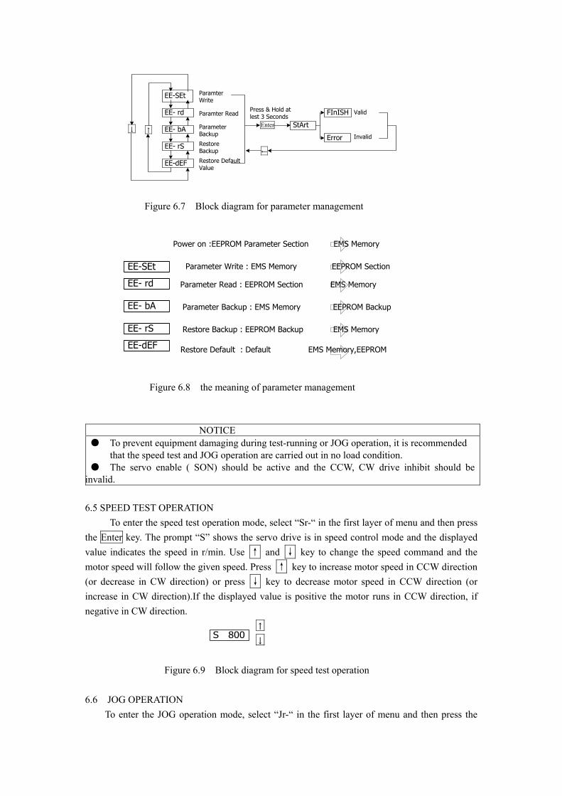
invalid. 6.5 SPEED TEST OPERATION To enter the speed test operation mode, select “Sr-“ in the first layer of menu and then press the Enter key. The prompt “S” shows the servo drive is in speed control mode and the displayed value indicates the speed in r/min. Use ↑ and ↓ key to change the speed command and the motor speed will follow the given speed. Press ↑ key to increase motor speed in CCW direction (or decrease in CW direction) or press ↓ key to decrease motor speed in CCW direction (or increase in CW direction).If the displayed value is positive the motor runs in CCW direction, if negative in CW direction.
S 800
↑
↓ Figure 6.9 Block diagram for speed test operation 6.6 JOG OPERATION To enter the JOG operation mode, select “Jr-“ in the first layer of menu and then press the
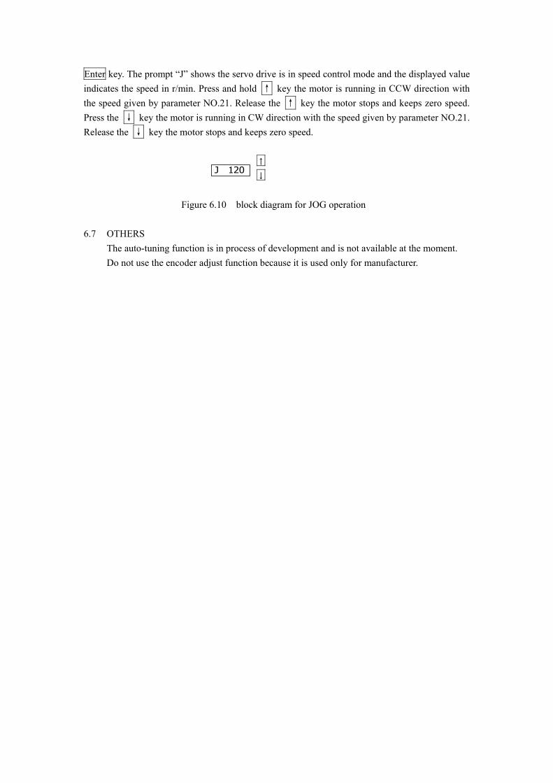
Enter key. The prompt “J” shows the servo drive is in speed control mode and the displayed value indicates the speed in r/min. Press and hold ↑ key the motor is running in CCW direction with the speed given by parameter NO.21. Release the ↑ key the motor stops and keeps zero speed. Press the ↓ key the motor is running in CW direction with the speed given by parameter NO.21. Release the ↓ key the motor stops and keeps zero speed.
J 120
↑
↓ Figure 6.10 block diagram for JOG operation 6.7 OTHERS
The auto-tuning function is in process of development and is not available at the moment. Do not use the encoder adjust function because it is used only for manufacturer.
1) If turn-on and turn-off the power supply more frequently, the soft-start circuit and the regenerative brake circuit may be caused failure. Therefor the turn-on /turn-off rate is limited to 5 times per hour or 30 times a day. When thermal failure occurs it is necessary to remove the failure cause and to cool the servo amplifier and /or servomotor at lest 30 minutes. Then the power supply can be switched on again.
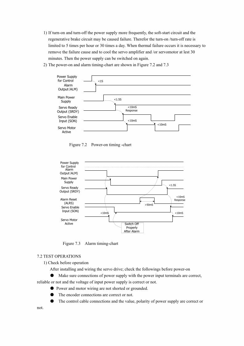
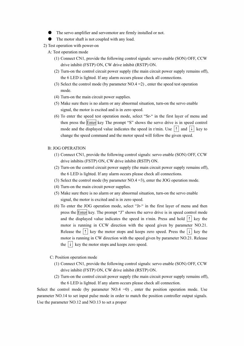
2) The power-on and alarm timing-chart are shown in Figure 7.2 and 7.3
Power Supplyfor Control
AlarmOutput(ALM)
Main PowerSupply
Servo ReadyOutput (SRDY)
Servo EnableInput (SON)
Servo MotorActive
<1S
<1.5S
<10mSResponse
<10mS<10mS
Figure 7.2 Power-on timing -chart
Power Supplyfor Control
AlarmOutput(ALM)
Main PowerSupply
Servo ReadyOutput (SRDY)
Servo MotorActive
<1.5S
<10mS
>50mS
Alarm Reset(ALRS)
<10mS
Switch OffProperly
After Alarm
<10mSResponse
Servo EnableInput (SON)
Figure 7.3 Alarm timing-chart 7.2 TEST OPERATIONS 1) Check before operation After installing and wiring the servo drive; check the followings before power-on ● Make sure connections of power supply with the power input terminals are correct, reliable or not and the voltage of input power supply is correct or not. ● Power and motor wiring are not shorted or grounded. ● The encoder connections are correct or not. ● The control cable connections and the value, polarity of power supply are correct or not.
● The servo amplifier and servomotor are firmly installed or not. ● The motor shaft is not coupled with any load. 2) Test operation with power-on A: Test operation mode
(1) Connect CN1, provide the following control signals: servo enable (SON) OFF, CCW drive inhibit (FSTP) ON, CW drive inhibit (RSTP) ON.
(2) Turn-on the control circuit power supply (the main circuit power supply remains off), the 6 LED is lighted. If any alarm occurs please check all connections.
(3) Select the control mode (by parameter NO.4 =2) , enter the speed test operation mode.
(4) Turn-on the main circuit power supplies. (5) Make sure there is no alarm or any abnormal situation, turn-on the servo enable
signal, the motor is excited and is in zero speed. (6) To enter the speed test operation mode, select “Sr-“ in the first layer of menu and
then press the Enter key The prompt “S” shows the servo drive is in speed control mode and the displayed value indicates the speed in r/min. Use ↑ and ↓ key to change the speed command and the motor speed will follow the given speed.
B: JOG OPERATION
(1) Connect CN1, provide the following control signals: servo enable (SON) OFF, CCW drive inhibits (FSTP) ON, CW drive inhibit (RSTP) ON.
(2) Turn-on the control circuit power supply (the main circuit power supply remains off), the 6 LED is lighted. If any alarm occurs please check all connections.
(3) Select the control mode (by parameter NO.4 =3), enter the JOG operation mode. (4) Turn-on the main circuit power supplies. (5) Make sure there is no alarm or any abnormal situation, turn-on the servo enable
signal, the motor is excited and is in zero speed. (6) To enter the JOG operation mode, select “Jr-“ in the first layer of menu and then
press the Enter key. The prompt “J” shows the servo drive is in speed control mode and the displayed value indicates the speed in r/min. Press and hold ↑ key the motor is running in CCW direction with the speed given by parameter NO.21. Release the ↑ key the motor stops and keeps zero speed. Press the ↓ key the motor is running in CW direction with the speed given by parameter NO.21. Release the ↓ key the motor stops and keeps zero speed.
C: Position operation mode
(1) Connect CN1, provide the following control signals: servo enable (SON) OFF, CCW drive inhibit (FSTP) ON, CW drive inhibit (RSTP) ON.
(2) Turn-on the control circuit power supply (the main circuit power supply remains off), the 6 LED is lighted. If any alarm occurs please check all connection.
Select the control mode (by parameter NO.4 =0) , enter the position operation mode. Use parameter NO.14 to set input pulse mode in order to match the position controller output signals. Use the parameter NO.12 and NO.13 to set a proper
(3) Electric gear ratio. (4) Turn-on the main circuit power supplies. (5) Make sure there is no alarm or any abnormal situation, turn-on the servo enable
signal, the motor is excited and is in zero speed. (6) The position controller provides the command pulse train to the servo amplifier
through connector CN1-6, 18, 7, 19 pin, the motor will run following the command pulse train.
D: Speed operation mode
(1) Connect CN1, provide the following control signals: servo enable (SON) OFF, CCW drive inhibit (FSTP) ON, CW drive inhibit (RSTP) ON, speed selection 1 (SC1), speed selection 2 (SC2).
(2) Turn-on the control circuit power supply (the main circuit power supply remains off), the 6 LED is lighted. If any alarm occurs please check all connection.
(3) Select the control mode (by parameter NO.4 =1), enter the speed operation mode. Use parameter NO.24~27 to set the required speed command.
(4) Turn-on the main circuit power supplies. (5) Make sure there is no alarm or any abnormal situation, turn-on the servo enable
signal, the motor is excited and is in zero speed. (6) By changing the input signals SC1 and/or SC2, the motor will runs with a speed
according to parameters of NO.24~27.
7.3 ADJUSTMENT NOTICE ● Make sure the parameters are correct before start the servo drive. Any wrong with Parameters may cause the servo drive running badly or accident. ● It is recommended that the no-load test is firstly carried and then the load test.
1) Basic gain adjustment A: Speed control loop
(1) Use parameter NO.5 to set the speed loop proportional gain. Under no oscillation condition the higher gain the better. In general, the larger load inertia the higher the setting value will be.
(2) Use parameter NO.6 to set the speed loop integration time constant. The value is determined according to the type of servo amplifier and the load.
Under no oscillation condition the smaller the time constant the better.
If the integration time constant is small the speed response is fast, but
oscillation may occur. If the integration time constant is large the motor
speed may change more when the load changed. In general, the larger load
inertia the higher the integration time constant will be.
B: Position control loop (1) First, according to speed control loop adjustment, set the speed loop proportional gain
and the speed loop integration time constant properly.
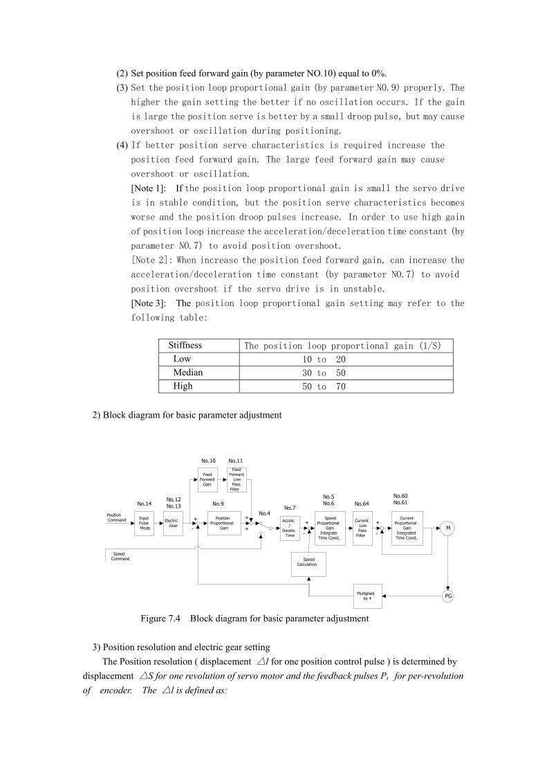
(2) Set position feed forward gain (by parameter NO.10) equal to 0%. (3) Set the position loop proportional gain (by parameter NO.9) properly. The
higher the gain setting the better if no oscillation occurs. If the gain
is large the position serve is better by a small droop pulse, but may cause
overshoot or oscillation during positioning. (4) If better position serve characteristics is required increase the
position feed forward gain. The large feed forward gain may cause
overshoot or oscillation. [Note 1]: If the position loop proportional gain is small the servo drive is in stable condition, but the position serve characteristics becomes
worse and the position droop pulses increase. In order to use high gain
of position loop increase the acceleration/deceleration time constant (by
parameter NO.7) to avoid position overshoot.
[Note 2]: When increase the position feed forward gain, can increase the
acceleration/deceleration time constant (by parameter NO.7) to avoid
position overshoot if the servo drive is in unstable.
[Note 3]: The position loop proportional gain setting may refer to the following table:
Stiffness The position loop proportional gain (1/S) Low 10 to 20
Median 30 to 50
High 50 to 70
2) Block diagram for basic parameter adjustment
InputPulseMode
ElectricGear
PositionProporttional
Gain
FeedForward
Gain
FeedForward
LowPass
Filter
Accele./
Decele.Time
SpeedProportional
GainIntegrate
Time Const.
CurrentLowPass
Filter
CurrentProportional
GainIntegratedTime Const.
SpeedCalculation
M
PGMultipliedby 4
PositionCommand
SpeedCommand
+
-
+
++ +
- -
No.14No.12No.13
No.10 No.11
No.9No.7
No.5No.6 No.64
No.60No.61
No.4
Figure 7.4 Block diagram for basic parameter adjustment 3) Position resolution and electric gear setting The Position resolution ( displacement △l for one position control pulse ) is determined by displacement △S for one revolution of servo motor and the feedback pulses Pt for per-revolution of encoder. The △l is defined as:
tPSl ∆
=∆
Where △l: displacement for one position control pulse (mm); △S: displacement for one revolution of servo motor (mm); Pt: the feedback pulses for per-revolution of encoder (pulse/revolution); Due to the pulse counter has a four multiple circuit, therefore the Pt = 4×C (C is the pulses of A or B of encoder). In this servo drive the C=2500 pulse / revolution, so the Pt = 10000 pulse / rev. The position control pulse is equal ti the product of command pulse and electric gear ratio, therefore the displacement of eachcommand pulse will be
GPSlt×
∆=∆ *
Where, G = Pre-scale numerator command pulse / Pre-scale denominator of command pulse. 4) Adjustment of start / stop characteristics
The start / stop characteristics of the servo drive (e.g. the acceleration / deceleration time) are depended on the load inertia, start / stop rate. It is also limited by the specifications of the servo drive. Start / stop frequently, acceleration / deceleration time is short, load inertia is large, etc. will cause the servo drive overheating alarm and / or overvoltage alarm. Therefore it is necessary to adjust the start / stop characteristics according to the reality satuation.
(1) load inertia and start / stop rate If the servo drive is used for a high start / stop rate condition, it is necessary to determind the maximum allowable start / stop rate which depends on the motor type and rated power, load inertia, motor speed. The recommended start / stop rate and acceleration / deceleration time (parameter NO.7) are listed below according to the ratio (m) of load inertia to motor inertia.
Load inertia ratio Allowable maximum start / stop rate (cycle / min)
Acceleration / deceleration time (ms)
m <= 3 >100 60 or less m <= 5 60 ~ 100 150 or less m > 5 < 60 150 or more
(2) Factor of servo motor
The maximum allowbale start / stop rate and acceleration / deceleration time also depend on the type of servo motor and on the load conditions, running time, envionmental temperature, etc. To avoid overheating alarm and influence on the servo motor life-time, please refer to the servo motor guide and adjust according to reality satuations.
(3) Method of adjustment
In general, the load inertia should be less than 5 times the inertia of the motor. If the load inertia is larger than the above mentioned it may cause overvoltage or brake abnormal alarm during deceleration. To deal with the above problem, use the following treatments: ● Increase acceleration / deceleration time (parameter NO.7). first, make it large, then reduce it gradually to a proper value.

● Reduce the torque limit (parameter NO34, NO. 35) and current limit; ● Reduce the maximum speed of the servo motor (parameter NO.23); ● Install an external regeneration brake equipment; ● Replace with lager rated power and inertia of servo motor.

CHAPTER 8 SPECIFICATIONS
! NOTICE
8.1 SPECIFICATIONS OF SERVO AMPLIFIER
Type DA98-04 DA98-06 DA98-08 DA98-10 DA98-12 DA98-14 DA98-15 Rated output (kW)
0.4 0.6 0.8 1.0 1.2 1.4 1.5
110STZ2-1-HM
110STZ2-2-HM
110STZ4-1-HM
110STZ5-1-HM
110STZ4-2-HM
130STZ7.5-1-HM
130STZ5-2-HM
Applicable servo motor
130STZ5-1-HM
110STZ6-1-HM
130STZ10-1-HM
Power supply Singe phase or three phase AC 220V –15~+10% 50/60 Hz
Three phase AC220V –15~+10% 50/60 Hz.
Environmental conditions
Refer to chapter 2 in Section 2-1.
Control mode 1) Position control, 2) Speed control, 3) Test speed run, 4) JOG run. Regenerative brake
Built-in
Speed frequency response: 200 Hz or higher Speed fluctuation ratio: (related to rated speed) <+/- 0.03 (load 0~100%); <+/- 0.02 (power supply –15~+10%) Speed control range: 1 : 5000
Features :
Input pulse rate : =< 500 Hz Control inputs 1) Servo enable, 2) Alarm reset, 3) CCW drive inhibit, 4) CW drive inhibit,
5) Deviation counter reset / speed select 1, 6) Command pulse inhibit / speed select 2 7) CCW torque limit, 8) CW torque limit.
Control outputs 1) Servo drive ready, 2) Servo drive alarm, 3) In-position, 4) reached speed. Input pulse mode: 1) pulse + sign. 2) CCW pulse / CW pulse. 3) Two-phase pulse trains with 90-degree phase shift each other. Electric gear ratio: 1~32767 / 1~32767
Position control
Feed back pulse: 10000 pulse / revolution. Speed control 1~4 internal speeds Acceleration / deceleration function
Parameter setting: 1~10000ms / 1000 rpm
Monitor function
Speed, current position, Command pulse accumulation, Position deviation, Motor torque, Motor current, Linear speed, Absolute rotor position, Command pulse rate, Operation state, Input and output signals etc.
Protective functions
Over-speed, Over-voltage / under-voltage of main power supply, Over-current, Over-load, Brake abnormal, Encoder abnormal, Control power supply abnormal, Exceed position error etc.
Operator 6 LED 7-Segment digit and 4 keys Applicable load inertia
5 times servo motor inertia or less.
Weight 2.8 kg
Dimensions 244×163×92 mm ( the outline is shown in fig.2.1).
8.2 SPECIFICATIONS OF SERVO MOTOR
1) Product introduction The New-Type Electric Machine Factory of Huazhong University of Science and Technology makes the STZ series AC permanent magnet synchronous servomotor. The series of servomotor has many advantages as the followings:
● The new-type rare- earth magnet material is used for the servomotor, resulting in higher output rating for low weight.
● The speed control range is about 1 : 10000, having excellent performance in low speed
● Safety for use with high dielectric strength and high insulation resistance. ● High torque over-load capability. The servomotor can withstand an instantaneous
torque at about eight times of the rated torque. 2) Terminals description
(1) Servomotor windings The windings of the servomotor is shown in the following: A, B, C are the terminals of the servomotor windings. T1, T2 are the terminals of the temperature sensor switch (it is a normal closed contactor. When overheating it will open) The connector of the servomotor is a P-type seven-pin male socket as showing in table 8.2 Table 8.2 The terminals of servomotor
Pin NO. 1 2 3 4 5 6 7 Symbol PE A B T1 T2 C
(2) Terminals of the encoder
The connector of the encoder is a P-type nineteen-pin male socket as showing in table 8.3 Table 8.3 the connections of the encoder Pin NO 1 2 3 4 5 6 7 8 9 10 11 12 13 14 19 Symbol
Vcc
GN
D
A
B
Z
_ A
_ B
_ Z
U
V
W
_ U
_ V
_ W
PE
(3) Specifications of servomotor
The specifications of some servomotors are listed in table 8.4.
Table 8.4 the specifications of servomotor
Type (new)
Type (old)
Power (kW)
Rated current (A)
Zero Speed torque (N-m)
Rated speed (rpm)
Rotor inertia (kg-m2) ×10-4
Mech. Time Const. (ms)
Volt. Vcd
weight (kg)
110STZ2-1-HM HD2-1-C 0.4 2.5 2 2000 5.4 12.6 300 11 110STZ2-2-HM HD2-2-C 0.6 4 2 3000 5.4 12.6 300 11 110STZ4-1-HM HD4-1-C 0.8 3 4 2000 9.1 5.9 300 14 110STZ4-2-HM HD4-2-C 1.2 5 4 3000 9.1 5.9 300 14 110STZ5-1-HM HD5-1-C 1.0 4 5 2000 11.0 6.0 300 15 110STZ6-1-HM HD6-1-C 1.2 4.5 6 2000 12.9 6.6 300 17 130STZ5-1-HM HD5-1-C 1.0 4 5 2000 20.0 10.0 300 15 130STZ5-2-HM HD5-2-C 1.5 5.5 5 3000 20.0 10.0 300 15 130STZ7.5-1-HM
HD7.5-1-C
1.4 5.5 7.5 2000 28.0 6.0 300 18
130STZ10-1-HM
HD10-1-C
1.4 5.5 10.0 1500 28.0 5.0 300 20
3) Outline dimension drawings (1) The outline dimension drawings of 110 frame of servomotor
Zero-speed torque (N-m)
2 4 5 6
D (mm) 19 19 22 22
L (mm) 194 232 251 270
(2) The outline dimension drawings of 130 frame of servomotor
Zero-speed torque (N-m) 5 7.5 10 L (mm) 200 225 250
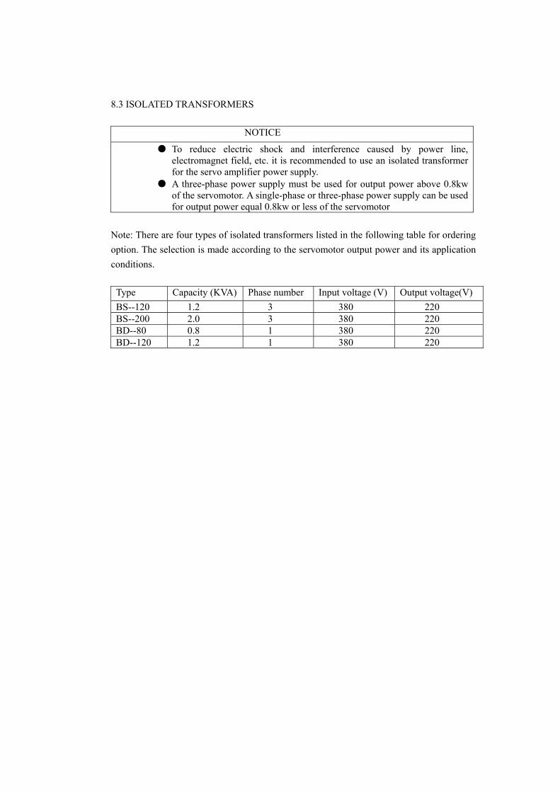
8.3 ISOLATED TRANSFORMERS
NOTICE
● To reduce electric shock and interference caused by power line, electromagnet field, etc. it is recommended to use an isolated transformer for the servo amplifier power supply.
● A three-phase power supply must be used for output power above 0.8kw of the servomotor. A single-phase or three-phase power supply can be used for output power equal 0.8kw or less of the servomotor
Note: There are four types of isolated transformers listed in the following table for ordering option. The selection is made according to the servomotor output power and its application conditions.
Type Capacity (KVA) Phase number Input voltage (V) Output voltage(V) BS--120 1.2 3 380 220 BS--200 2.0 3 380 220 BD--80 0.8 1 380 220 BD--120 1.2 1 380 220
CHAPTER 9 ORDER GUIDELINE 9.1 CAPACITY SELECTION
To determination the capacity of servo drive it is necessary to make considerations of load inertia, load torque, required positioning accuracy and maximum speed. The following procedure for above considerations is recommended:
1) Calculate load inertia and torque For further calculations it is necessary to calculate load inertia, load torque, acceleration / deceleration torque and effective torque according to relative data.
2) Determine the mechanical gear ratio for the first time According to the required maximum speed and servo motor maximum speed the maximum mechanical gear ratio can be calculated. Then check and ratify the required minimum-moving unit by the gear ratio and the servo motor minimum-moving unit. If the required positioning accuracy is higher than the calculated value it is possible to increase the mechanical ratio (it will reduce the maximum speed) or to use a higher rated speed servomotor.
3) Check load inertia and torque The load inertia and load torque is converted to their equivalent values related to servo motor shaft. The equivalent inertia should be equal or less than five times rotor inertia. The equivalent load torque and effective torque should be less than the rated torque of servomotor. If any above requirement is not fulfill it is necessary to increase the gear ratio (reduce the maximum speed) or to select larger capacity of servo drive.
9.2 ELETRIC GEAR RATIO Refer to chapter 4 (table 4.2 parameter function), chapter 6 (6.3 parameter setting) and chapter 7 (7.3 adjustment) for understanding of electric gear ratio and its adjustment. Under position control mode the actual load speed will be: Command pulse rate × G × gear ratio
Under position control mode the actual minimum displacement will be: Minimum command pulse moving unit × G × gear ratio
Note: If the electric gear ratio is not equal to one the division calculation of mechanical gear ratio may have a remainder resulting in position deviation. The maximum position deviation equals to the minimum rotation unit (e.g. minimum resolution). 9.3 STOPPING CHARACTERISTICS Under position control mode the servo drive controlled by pulse train, there is a difference between command pulse train and feedback pulse train. It is called as delay pulse and will be accumulated in the position deviation counter. The relationship of the command pulse rate, electric gear ratio and the position loop gain is as the follows:
pKGf ×
=*
ε
Where: ε: delay pulse (pulse); f* : command pulse rate (Hz); Kp : position loop gain (1/S); G : electric gear ratio. Note : The above relation is obtained if the position feed forward gain is equal to zero. Otherwise the delay pulse will be smaller than the calculation of the formulator.
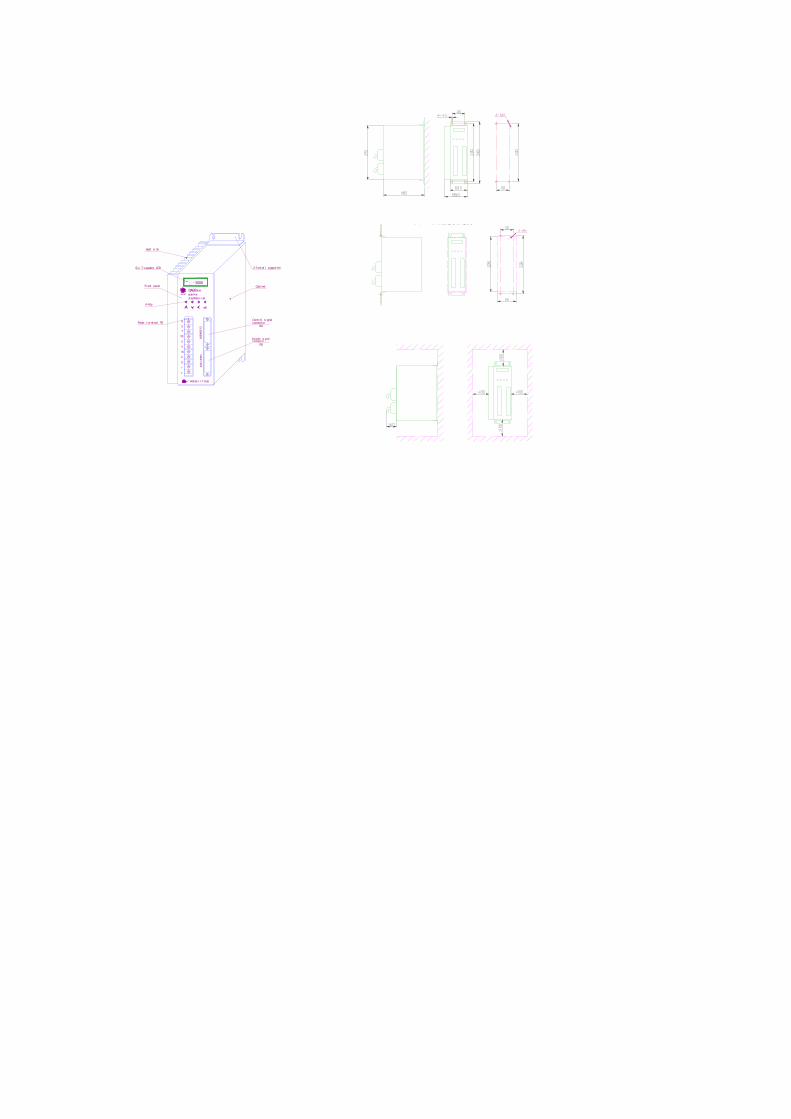
DA98
交流侗服 器驱动
R
S
T
PE
U
V
W
P
D
r
t
广州数控 厂制造设备
系列
CN1控
制信
号CN2
反信
号馈
-3000
全数字式GSKCNC
connect or
connect or
Heat si nk
Si x 7-segment LED
Fr ont panel
4- Key
Power t ermi nal TB
Cabi net
2- Inst al l suppor t er
CN2
CN1
Cont rol si gnal
Encoder si gnal
图 器底板安装方驱动