lactoscan sa
TRANSCRIPT
Ultrasonic milk analyser
Operation manual 11.04.19 1/110
Milkotronic Ltd
LACTOSCAN SA MILK ANALYZER
LCD display – 4 lines x 16 characters
Operation manual
Ultrasonic milk analyser
Operation manual 11.04.19 2/110
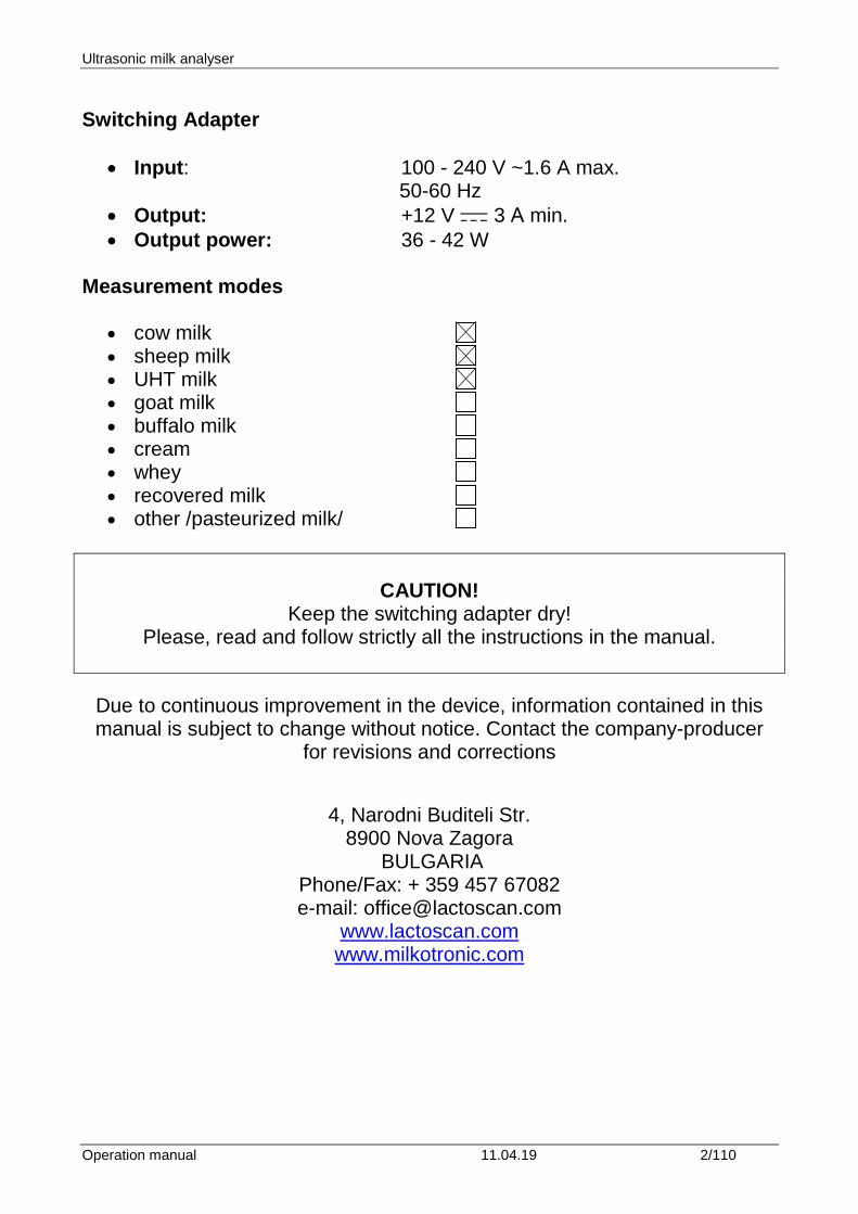
Switching Adapter
• Input: 100 - 240 V ~1.6 A max. 50-60 Hz
• Output: +12 V 3 А min. • Output power: 36 - 42 W
Measurement modes
• cow milk • sheep milk • UHT milk • goat milk • buffalo milk • cream • whey • recovered milk • other /pasteurized milk/
CAUTION! Keep the switching adapter dry!
Please, read and follow strictly all the instructions in the manual.
Due to continuous improvement in the device, information contained in this manual is subject to change without notice. Contact the company-producer
for revisions and corrections
4, Narodni Buditeli Str. 8900 Nova Zagora
BULGARIA Phone/Fax: + 359 457 67082 e-mail: [email protected]
www.lactoscan.com www.milkotronic.com
Ultrasonic milk analyser
Operation manual 11.04.19 3/110
SAFETY INSTRUCTIONS
1. Read this manual carefully and make sure that you understand all the
instructions. 2. For safety purposes the device is equipped with grounded power
cable. If there is no grounded electrical outlet where the device will be used, please, install such before using the device.
3. Place the device on leveled and stable plate. In case it falls or is
severely shocked it may be damaged. 4. Connect to the electrical network in such a way that the power cable
to stay away from the side for accessing the device and not to be stepped on.
5. Every time before cleaning the device switch it off and unplug it from
the electrical outlet. The device has to remain unplugged till the cleaning completion.
6. Do not disassemble the unit in order to avoid possible electrical
shock. In case of malfunction contact your local dealer. 7. Handle the liquids the device works with carefully, following all the
instructions for their preparation. 8. Place the switching adaptor in such a way as to be protected from
overflow and spillage of liquids.
Ultrasonic milk analyser
Operation manual 11.04.19 4/110
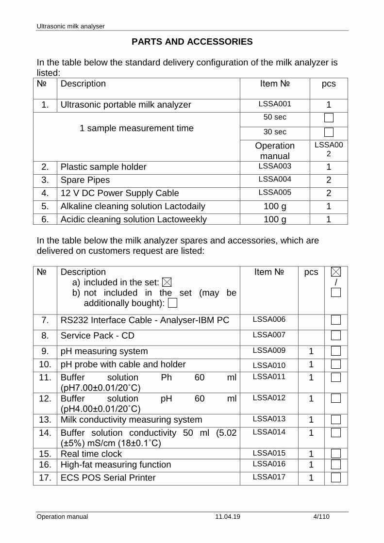
PARTS AND ACCESSORIES
In the table below the standard delivery configuration of the milk analyzer is listed: № Description
Item № pcs
1. Ultrasonic portable milk analyzer LSSA001 1
1 sample measurement time 50 sec 30 sec
Operation manual
LSSA002
2. Plastic sample holder LSSA003 1 3. Spare Pipes LSSA004 2 4. 12 V DC Power Supply Cable LSSA005 2 5. Alkaline cleaning solution Lactodaily 100 g 1 6. Acidic cleaning solution Lactoweekly 100 g 1
In the table below the milk analyzer spares and accessories, which are delivered on customers request are listed: № Description
a) included in the set: b) not included in the set (may be
additionally bought):
Item № pcs /
7. RS232 Interface Cable - Analyser-IBM PC LSSA006
8. Service Pack - CD LSSA007
9. pH measuring system LSSA009 1 10. pH probe with cable and holder LSSA010 1 11. Buffer solution Ph 60 ml
(pH7.00±0.01/20˚C) LSSA011 1
12. Buffer solution pH 60 ml (pH4.00±0.01/20˚C)
LSSA012 1
13. Milk conductivity measuring system LSSA013 1 14. Buffer solution conductivity 50 ml (5.02
(±5%) mS/cm (18±0.1˚C) LSSA014 1
15. Real time clock LSSA015 1 16. High-fat measuring function LSSA016 1 17. ECS POS Serial Printer LSSA017 1
Ultrasonic milk analyser
Operation manual 11.04.19 5/110
18. 12 V Serial Printer Power Supply Cable LSSA018 1 19. RS232 Interface Cable - Milk Analyser –
Serial Printer LSSA019 1
20. Carrying case LSSA020 1 21. Plug type
1
1
22. Spare O-ring for the pH probe 1 23. USB flash drive (slot) 1
Ultrasonic milk analyser
Operation manual 11.04.19 6/110
1. FUNCTION The function of the milk analyzer is to make quick analysis of milk on fat (FAT), non-fat solids (SNF), proteins, lactose and water content percentages, temperature (oС), pH, freezing point, salts, total solids, conductivity as well as density of one and the same sample directly after milking, at collecting and during processing.
Ultrasonic milk analyser
Operation manual 11.04.19 7/110
2. TECHNICAL PARAMETERS 2.1. Working modes characteristics: The program of the milk analyzer has four working modes. 2.1.1. Measurement mode milk / dairy product – first type 2.1.2. Measurement mode milk / dairy product – second type 2.1.3. Measurement mode UHT milk / dairy product – third type These modes have been calibrated on customers’ request for 3 milk types from the following: cow, sheep, UHT, buffalo, goat, camel milk, cream, ice cream mixtures, whey, recovered milk, etc. before leaving the production facilities and the text on the display will be for the corresponding types, as is indicated on page 2 Measurement modes. 2.1.4. Cleaning 2.1.4.1. Current 2.1.4.2. Final Note: For devices with a 5 button keypad on the front panel by pressing the extra buttons, you can run the following commands: Pressing the button labeled A - start re-printing the results Pressing the button labeled B - start of flushing (2.1.4.) These commands are possible when the unit is in Idle mode, i.e. expecting command for measuring sample.
Ultrasonic milk analyser
Operation manual 11.04.19 8/110
2.2. Measuring range: Fat ………………..................... …………..from 0.01% to 25% (45%*) SNF ……………………………… ...…………………....from 3% to 40% Density ** ………………………. ……...…….from 1000 to 1150 kg/m3 Proteins …………………………. ………………………..from 2% to 7% Lactose ………………………... …………………from 0.01 % to 20 % Water content ………………… ……………...……..from 0 % to 70 % Temperature of milk …………… from 1oC to 40oC (if measurement is
30 sec, then t° is from 15 to 40°) Freezing point ***.……………… …………..from – 0,400 to – 0,700oC Salts ……………………………. …...…………...………from 0,4 to 4% PH*..……………………………... …………………..………from 0 to 14 Conductivity* ** ………………… ……………...…from 3 to 14 [mS/cm] Total Solids* ……………………. ………………………...from 0 to 50 %
* Option, on customers’ request ** Density data are shown in an abbreviated form. For example 27.3 have to be understood as 1027.3 kg/m3. To determine the milk density, write down the result from the display and add 1000. Example: result 21,20; density = 1000 + 21,20 = 1021,2 kg/m3 The abbreviated form of the density is used also when entering data for samples in working mode Recalibrate, for example: If the measured sample density is 1034.5 kg/m3, then in the menu for entering the samples parameters used for calibration, across the parameter Den = , you have to enter 34.5. *** pH and conductivity measurements are optional and are embedded in the device on customers' request. **** Please, carefully read Appendix Freezing Point. 2.3. Accuracy: Fat …..……………………………….. …...………………….…...± 0.06% SNF ………………………………….. …………...………….…...± 0.15% Density ……………………………… ………………………..± 0.3 kg/m3 Proteins ……………………………... ……...……………….…...± 0.15% Lactose ……………………………… .…………………………...± 0.20% Water content ………………………. .…………………………….± 3.0% Temperature of milk ……………….. .………………………………± 1oC Freezing point……………………….. ..……...…………………± 0.005oC Salts ………………………………... …..…………...…………...± 0.05%
Ultrasonic milk analyser
Operation manual 11.04.19 9/110
PH……………………………………. ………………………………±0.05 Conductivity....………………………. ……………………………...±0.05 Total solids …………………………. ……………………………± 0.17%
2.4 Correct ambient conditions: Accuracy is guaranteed in case of normal ambient conditions: Air temperature………………………… ….…from 10oC to 40oC (43 oC) Relative humidity ……………………… ……………...from 30% to 80% Power supply ………………………… …………………...220V (110V) extent of contamination at normal environmental conditions
…………………….…………..2
Accuracy values in point 2.3 are in dependence on the correctness of the corresponding chemical method, used for component content determination. In point 2.3. are used the following reference methods: Gerber – for fat, gravimetric – for SNF, Kjeldahl – for protein. The boundary for maximum variation of repeatability when the power supply voltage is from +10 to – 15% from the nominal voltage values (220V) have to be no more than 0.8 accuracy according point 2.3. The analyser is used in conditions free of outer electrical and magnetic fields (except the magnetic field of the Earth) and vibrations. 2.5. Dimensions: ……………………………..240/220/100 mm, mass 3,0 kg 2.6. Continuous working time: ………………………………………non-stop 2.7 Milk sample volume per one measurement: ………..15 cm3 (= 25 ml)
Ultrasonic milk analyser
Operation manual 11.04.19 10/110
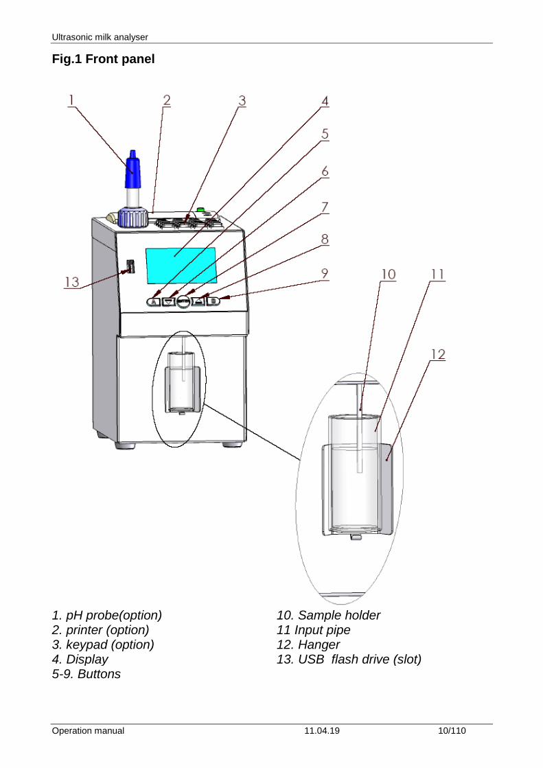
Fig.1 Front panel
1. pH probe(option) 10. Sample holder 2. printer (option) 11 Input pipe 3. keypad (option) 12. Hanger 4. Display 13. USB flash drive (slot) 5-9. Buttons
Ultrasonic milk analyser
Operation manual 11.04.19 11/110
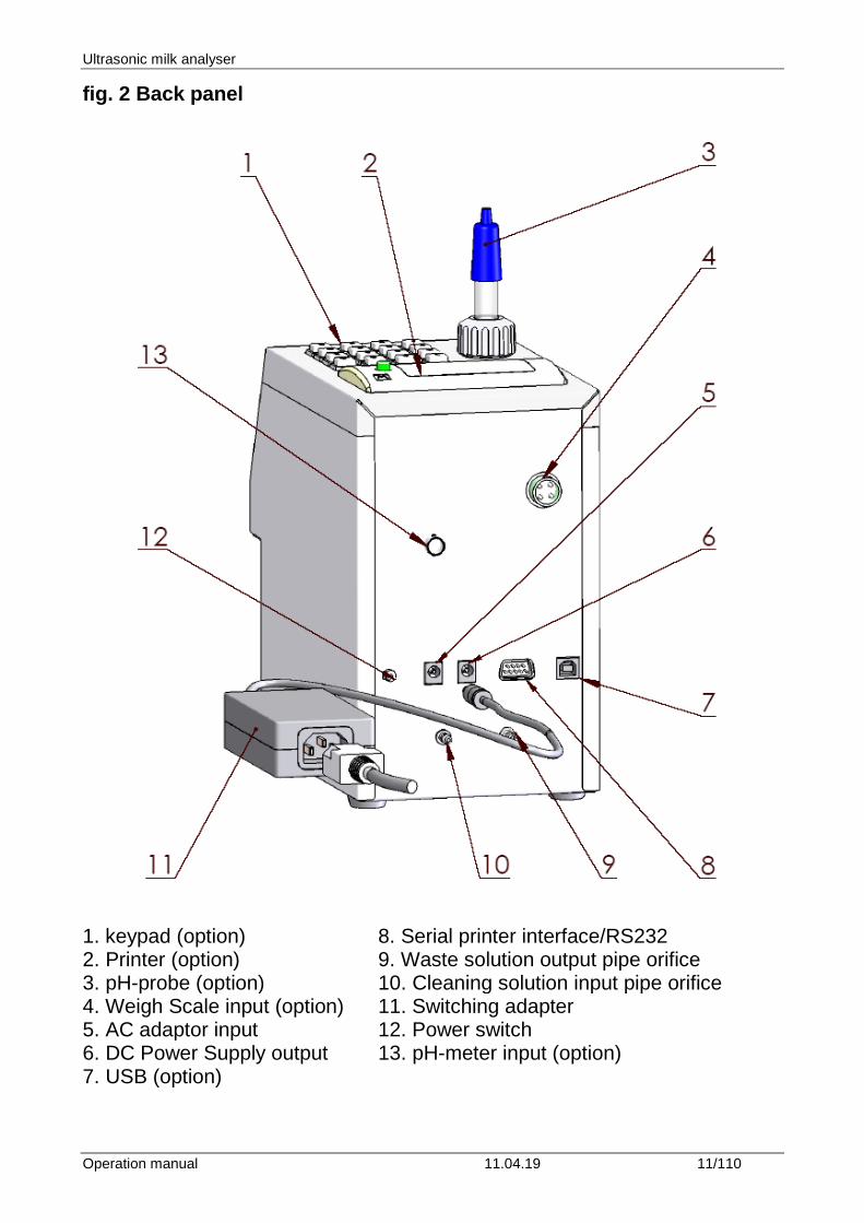
fig. 2 Back panel
1. keypad (option) 8. Serial printer interface/RS232 2. Printer (option) 9. Waste solution output pipe orifice 3. pH-probe (option) 10. Cleaning solution input pipe orifice 4. Weigh Scale input (option) 11. Switching adapter 5. AC adaptor input 12. Power switch 6. DC Power Supply output 13. pH-meter input (option) 7. USB (option)
Ultrasonic milk analyser
Operation manual 11.04.19 12/110
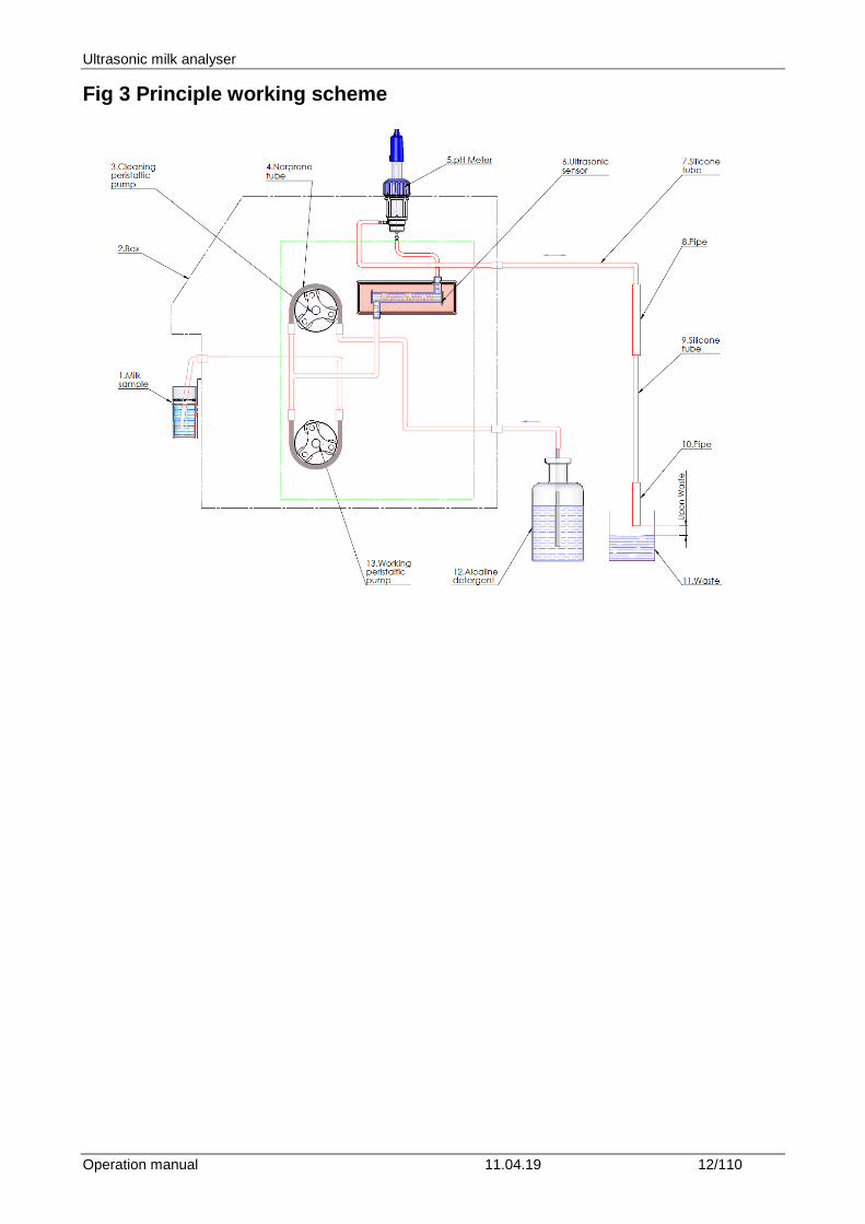
Fig 3 Principle working scheme
Ultrasonic milk analyser
Operation manual 11.04.19 13/110
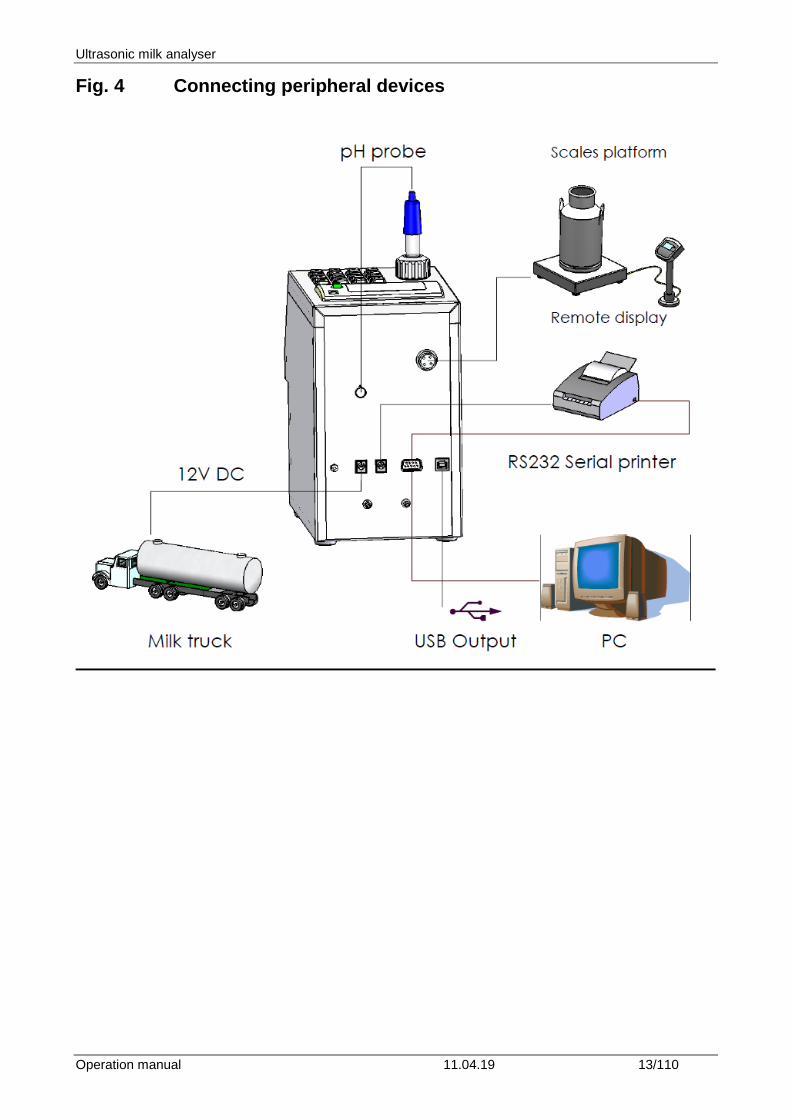
Fig. 4 Connecting peripheral devices
Ultrasonic milk analyser
Operation manual 11.04.19 14/110
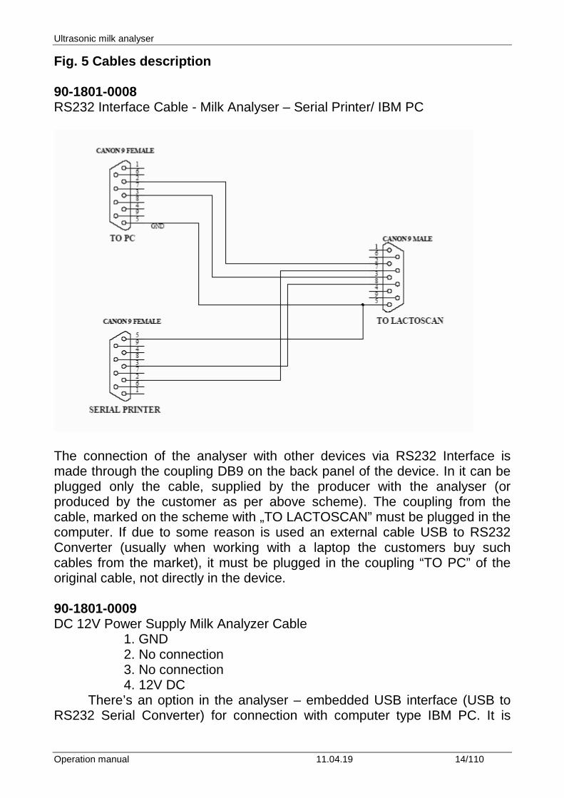
Fig. 5 Cables description 90-1801-0008 RS232 Interface Cable - Milk Analyser – Serial Printer/ IBM PC
The connection of the analyser with other devices via RS232 Interface is made through the coupling DB9 on the back panel of the device. In it can be plugged only the cable, supplied by the producer with the analyser (or produced by the customer as per above scheme). The coupling from the cable, marked on the scheme with „TO LACTOSCAN” must be plugged in the computer. If due to some reason is used an external cable USB to RS232 Converter (usually when working with a laptop the customers buy such cables from the market), it must be plugged in the coupling “TO PC” of the original cable, not directly in the device. 90-1801-0009 DC 12V Power Supply Milk Analyzer Cable 1. GND 2. No connection 3. No connection 4. 12V DC
There’s an option in the analyser – embedded USB interface (USB to RS232 Serial Converter) for connection with computer type IBM PC. It is
Ultrasonic milk analyser
Operation manual 11.04.19 15/110
intended for connecting computers from laptop type, which have no RS 232 interface (COM Ports – DB9 Connector). This option may be available together with the standard RS232 – connector DB9, which always exists in the analyzers. At one and the same time, connection analyzer – computer, can be established only through one of the couplings – either only DB9, or only USB, i.e. analyzer could not be connected at one and the same time, using one of the interfaces with one and using the other interface to another, second computer. The coupling for this option (Printer Type) is at the back of the analyzer, next to the standard RS232 DB9 connector. Other USB devices like printers, keypads etc COULD NOT be connected to this coupling.
USB interface is based on the element MCP2200 of the company Microchip Technology Inc. – site: http://www.microchip.com. For establishing a connection through this interface a driver has to be installed for MCP2200 in the correspondent computer, which will be connected with the analyzer. Please, follow the procedure, from the Internet site of the producer: http://www.microchip.com/wwwproducts/devices.aspx?ddocname=en546923, by choosing the suitable for your operation system driver.
After installing the driver, choose the СОМ port, which will be used for the real communication. For Win XP it is done by executing the following commands: Start -> Settings -> Control panel -> System -> Hardware -> Device Manager -> Ports (COM and LPT) – Right Click -> Properties -> Port Settings -> Advanced -> COM Port Number. Choose Number 1 or if another number is chosen, for example 3, then, when working with the software tools, in the field COM Port (upper right corner), you have to set the new number of the port, in this case 3.
Ultrasonic milk analyser
Operation manual 11.04.19 16/110
3. QUALIFICATION OF RAW MILK, THERMALLY TREATED MILK, OTHER DAIRY PRODUCTS AND DERIVATIVES 3.1. Taking samples and preparation for analysis In order to receive reliable results in qualification of milk, dairy products and derivatives are needed: precise samples taking; correct samples storing (in need to be preserved); correct preparation before making measurement. The rules and requirements for this are described in details in Appendix Milk sampling.
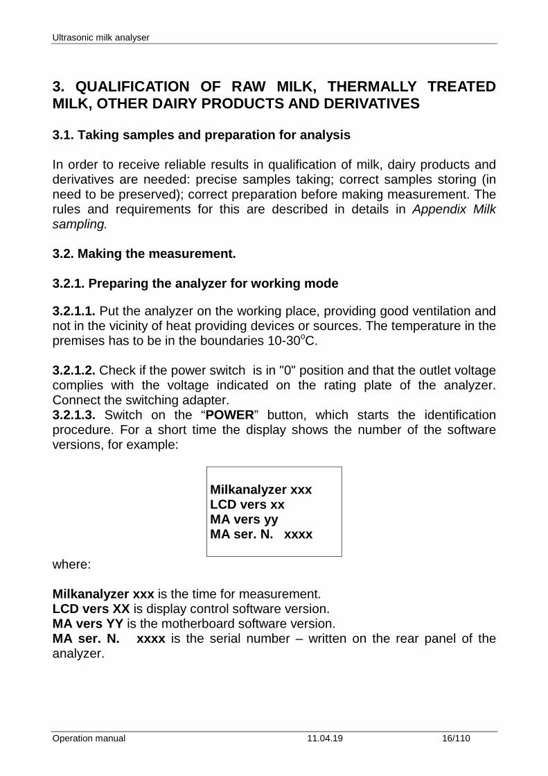
3.2. Making the measurement. 3.2.1. Preparing the analyzer for working mode 3.2.1.1. Put the analyzer on the working place, providing good ventilation and not in the vicinity of heat providing devices or sources. The temperature in the premises has to be in the boundaries 10-30oC. 3.2.1.2. Check if the power switch is in "0" position and that the outlet voltage complies with the voltage indicated on the rating plate of the analyzer. Connect the switching adapter. 3.2.1.3. Switch on the “POWER” button, which starts the identification procedure. For a short time the display shows the number of the software versions, for example:
Milkanalyzer xxx LCD vers xx MA vers yy MA ser. N. xxxx
where: Milkanalyzer xxx is the time for measurement. LCD vers XX is display control software version. MA vers YY is the motherboard software version. MA ser. N. xxxx is the serial number – written on the rear panel of the analyzer.
Ultrasonic milk analyser
Operation manual 11.04.19 17/110
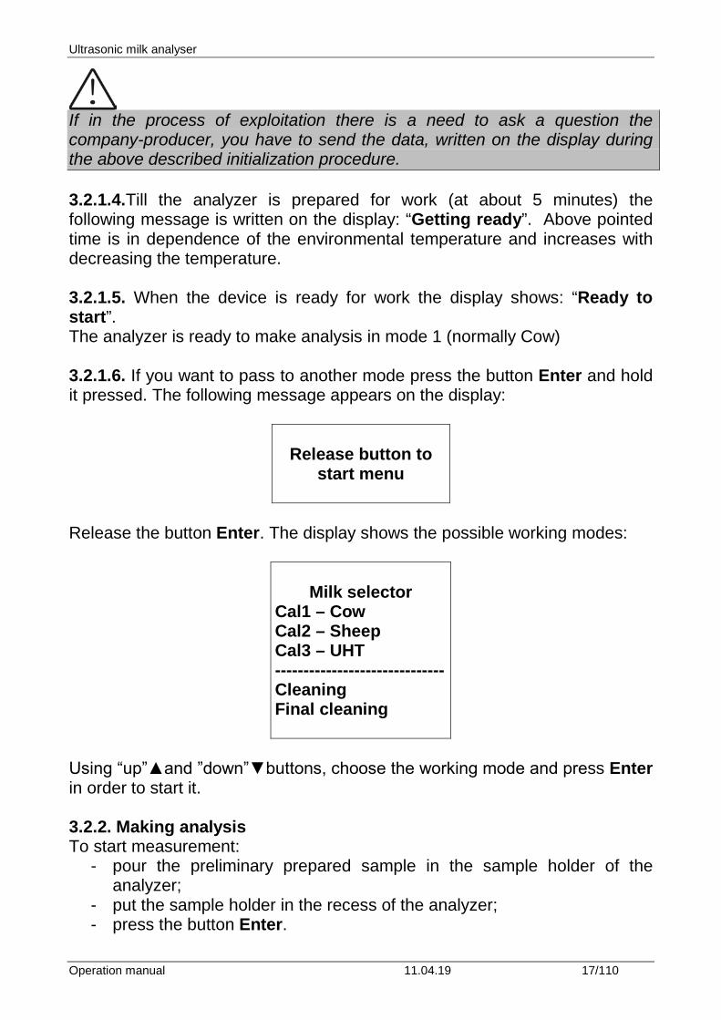
If in the process of exploitation there is a need to ask a question the company-producer, you have to send the data, written on the display during the above described initialization procedure. 3.2.1.4.Till the analyzer is prepared for work (at about 5 minutes) the following message is written on the display: “Getting ready”. Above pointed time is in dependence of the environmental temperature and increases with decreasing the temperature. 3.2.1.5. When the device is ready for work the display shows: “Ready to start”. The analyzer is ready to make analysis in mode 1 (normally Cow) 3.2.1.6. If you want to pass to another mode press the button Enter and hold it pressed. The following message appears on the display:
Release button to
start menu
Release the button Enter. The display shows the possible working modes:
Milk selector
Cal1 – Cow Cal2 – Sheep Cal3 – UHT ------------------------------ Cleaning Final cleaning
Using “up”▲and ”down”▼buttons, choose the working mode and press Enter in order to start it. 3.2.2. Making analysis To start measurement:
- pour the preliminary prepared sample in the sample holder of the analyzer;
- put the sample holder in the recess of the analyzer; - press the button Enter.
Ultrasonic milk analyser
Operation manual 11.04.19 18/110
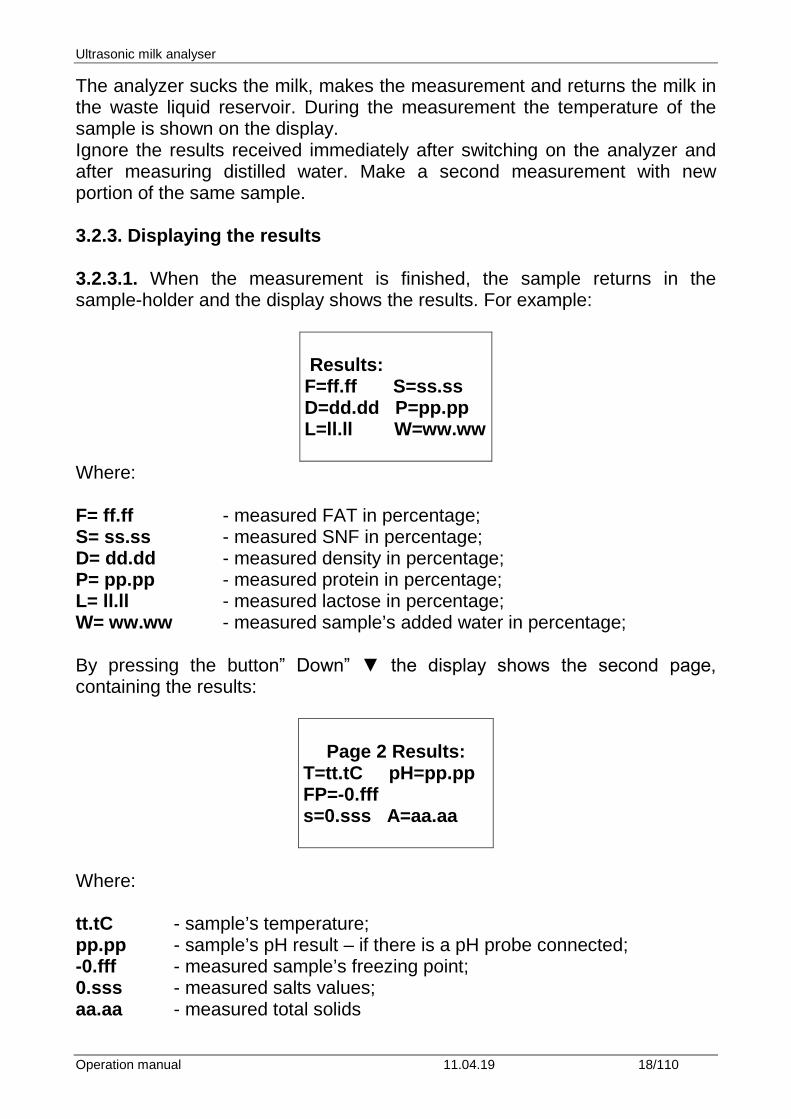
The analyzer sucks the milk, makes the measurement and returns the milk in the waste liquid reservoir. During the measurement the temperature of the sample is shown on the display. Ignore the results received immediately after switching on the analyzer and after measuring distilled water. Make a second measurement with new portion of the same sample. 3.2.3. Displaying the results 3.2.3.1. When the measurement is finished, the sample returns in the sample-holder and the display shows the results. For example:
Results: F=ff.ff S=ss.ss D=dd.dd P=pp.pp L=ll.ll W=ww.ww
Where: F= ff.ff - measured FAT in percentage; S= ss.ss - measured SNF in percentage; D= dd.dd - measured density in percentage; P= pp.pp - measured protein in percentage; L= ll.ll - measured lactose in percentage; W= ww.ww - measured sample’s added water in percentage; By pressing the button” Down” ▼ the display shows the second page, containing the results:
Page 2 Results:
T=tt.tC pH=pp.pp FP=-0.fff s=0.sss A=aa.aa
Where: tt.tC - sample’s temperature; pp.pp - sample’s pH result – if there is a pH probe connected; -0.fff - measured sample’s freezing point; 0.sss - measured salts values; aa.aa - measured total solids
Ultrasonic milk analyser
Operation manual 11.04.19 19/110
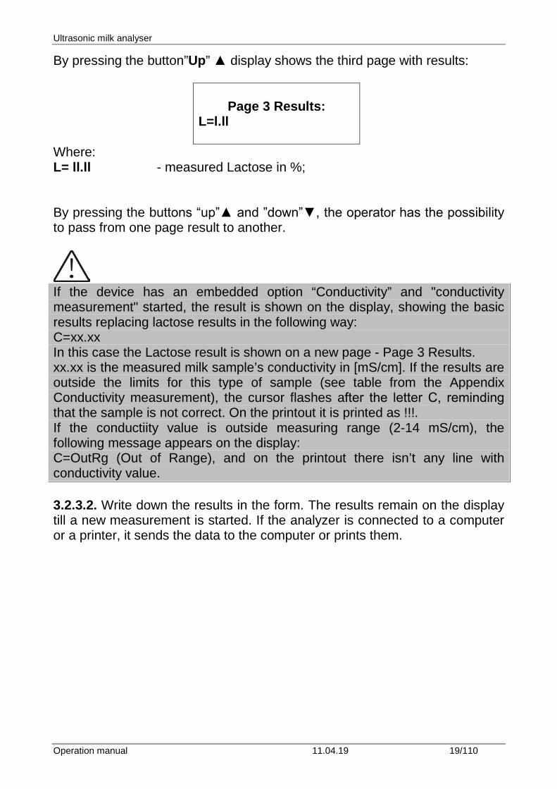
By pressing the button”Up” ▲ display shows the third page with results:
Page 3 Results:
L=l.ll
Where: L= ll.ll - measured Lactose in %; By pressing the buttons “up”▲ and ”down”▼, the operator has the possibility to pass from one page result to another.
If the device has an embedded option “Conductivity” and "conductivity measurement" started, the result is shown on the display, showing the basic results replacing lactose results in the following way: C=xx.xx In this case the Lactose result is shown on a new page - Page 3 Results. xx.xx is the measured milk sample’s conductivity in [mS/cm]. If the results are outside the limits for this type of sample (see table from the Appendix Conductivity measurement), the cursor flashes after the letter С, reminding that the sample is not correct. On the printout it is printed as !!!. If the conductiity value is outside measuring range (2-14 mS/cm), the following message appears on the display: C=OutRg (Out of Range), and on the printout there isn’t any line with conductivity value. 3.2.3.2. Write down the results in the form. The results remain on the display till a new measurement is started. If the analyzer is connected to a computer or a printer, it sends the data to the computer or prints them.
Ultrasonic milk analyser
Operation manual 11.04.19 20/110
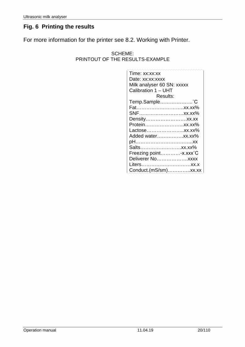
Fig. 6 Printing the results For more information for the printer see 8.2. Working with Printer.
SCHEME: PRINTOUT OF THE RESULTS-EXAMPLE
Time: xx:xx:xx Date: xx:xx:xxxx Milk analyser 60 SN: xxxxx Calibration 1 – UHT
Results: Temp.Sample………………..˚C Fat………………………..xx.xx% SNF………………………xx.xx% Density…………………….xx.xx Protein…………………...xx.xx% Lactose…………………..xx.xx% Added water…………….xx.xx% pH……………………………..xx Salts…………………….xx.xx% Freezing point…………-x.xxx˚C Deliverer No……………….xxxx Liters…………………………xx.x Conduct.(mS/sm)…………..xx.xx
Ultrasonic milk analyser
Operation manual 11.04.19 21/110
4. CLEANING THE ANALYZER This procedure prevents gathering milk fat residues and milk stone on the sensor. The milk stone consists of milk solids, calcium, iron, sulphates, magnesium, etc. All these substances form layer on the pipe and sensor’s walls, which leads to deviations in the measurement results and blocking up the piping.
The company-producer recommends usage of the chemicals, supplied with the analyser – alkaline and acidic (Lactodaily and Lactoweekly). You may order them separately or together with the analyser. Try to use only these chemicals for cleaning the analyser. In case you missed to order these chemicals, the alternative is to use alkaline and acidic cleaning solutions for dairy equipment by one the companies, producing such chemicals, as for example: http://www.diversey.com http://www.ecolab.com http://www.calvatis.com 4.1. Automatic cleaning the analyzer Analyzer's contamination as a result of the irregular cleaning is the basic reason for inexactness during measurement. In order to be avoid this, in the milk analyzers with peristaltic pump is embedded automatic cleaning. For this purpose the analyzer has to be prepared on the following way:
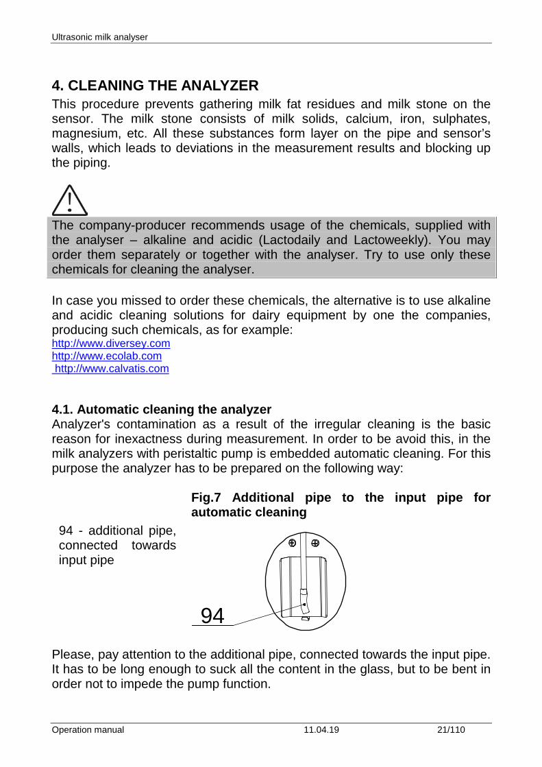
Fig.7 Additional pipe to the input pipe for automatic cleaning
94
Please, pay attention to the additional pipe, connected towards the input pipe. It has to be long enough to suck all the content in the glass, but to be bent in order not to impede the pump function.
94 - additional pipe, connected towards input pipe
Ultrasonic milk analyser
Operation manual 11.04.19 22/110
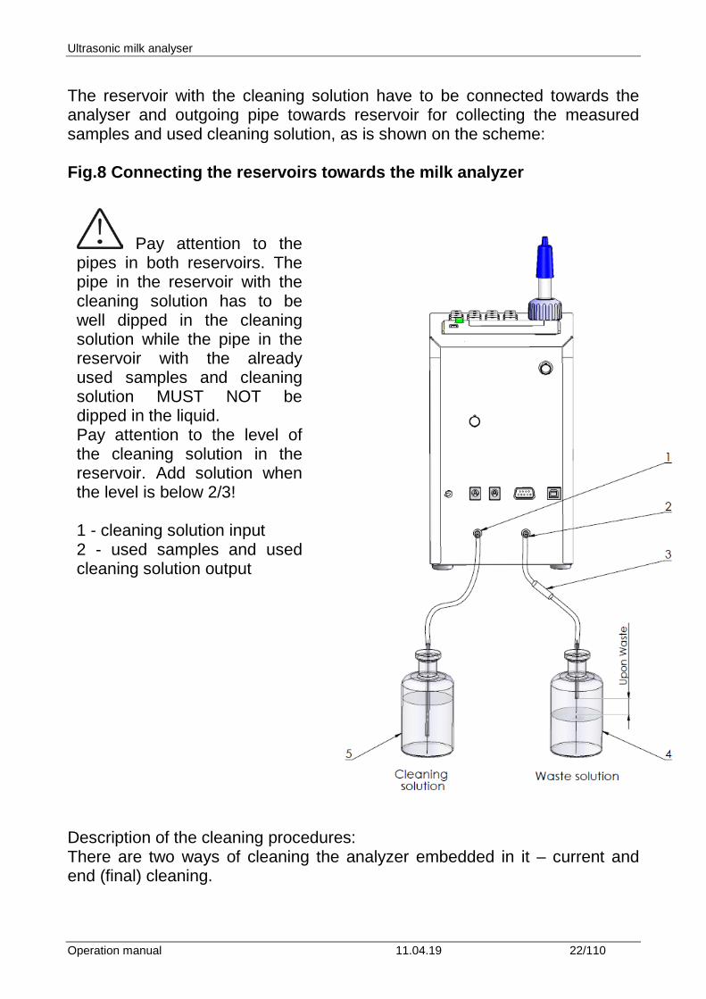
The reservoir with the cleaning solution have to be connected towards the analyser and outgoing pipe towards reservoir for collecting the measured samples and used cleaning solution, as is shown on the scheme: Fig.8 Connecting the reservoirs towards the milk analyzer
Description of the cleaning procedures: There are two ways of cleaning the analyzer embedded in it – current and end (final) cleaning.
Pay attention to the pipes in both reservoirs. The pipe in the reservoir with the cleaning solution has to be well dipped in the cleaning solution while the pipe in the reservoir with the already used samples and cleaning solution MUST NOT be dipped in the liquid. Pay attention to the level of the cleaning solution in the reservoir. Add solution when the level is below 2/3! 1 - cleaning solution input 2 - used samples and used cleaning solution output
Ultrasonic milk analyser
Operation manual 11.04.19 23/110
4.1.1. Current cleaning. 4.1.1.1. Automatic start
The current cleaning is made with 3% alkaline solution (for working solution preparation see 4.2.1.), with which the reservoir for the cleaning solution is filled in. It is automatically started, without operator's interference after the set time intevals elapse
1. 55 min. after switching on the power supply of the analyser, but idle* work;
2. 15 min. after the last measurement of real milk sample. *Idle Mode is that part of the standard working mode, when the analyser is not making measurements. There’s embedded in the analyser system for measurement of the idle time. The idle time is measured starting from the last action of the operator. In dependence of it (what the operator last did), are taken decisions regarding the cleaning.
There are 2 options:
Option A: If the analyser:
1. Was only switched on but was not started in measurement mode,
2. Or the last action was cleaning,
3. Or the last action was measuring sample with very low Fat (similar to water)
Then the automatic cleaning is started after 55 min.
Option B: If the last thing done with the analyser was measurement of normal milk sample, the automatic cleaning is started after 15 min. The display shows the following message and a sound signal is emitted:
Auto clean
started! Put empty glass
After this the cleaning is started. The display shows:
Ultrasonic milk analyser
Operation manual 11.04.19 24/110
Cleaning
Please wait
If there is a glass with sample it is completely emptied and then the analyser automatically fulfills procedure for sucking the cleaning solution and c rinsing the analyzer's inner system. In order the input metal pipe to be cleaned out for a short time a cleaning solution is pumped out for a short time in the already empty glass. It is filled to the middle and then is sucked back and poured in the reservoir with the used liquids. If there wasn't glass before the start of the automatic cleaning and if you do not replace it or put an empty glass then the cleaning solution will be poured in front of the device. After the cleaning is finished the displays shows the following:
End of cleaning
After 2 seconds the display shows:
Analyzer ready
Then the analyser is ready for normal measurement. 4.1.1.2. Manual start The current cleaning may be completed by manual start of the menu Cleaning. It is used before starting the menu Final Clean. It serves for cleaning the fats from the measuring tract with alkaline cleaning solution. It is started using the menu for choosing the working mode of the analyzer. After the measurement is completes, by continuous pressing the button Enter, the possible analyser operation modes are shown on the display.
Cow Sheep UHT Cleaning Final Clean
Ultrasonic milk analyser
Operation manual 11.04.19 25/110
By choosing Cleaning the current cleaning is started. The display shows the following:
Auto clean
started! Put empty glass
In this way the current cleaning is started. The procedure and operator’s actions are described above.
Do not switch off the device at the end of the working day before the automatic cleaning procedure is completed. If it is not automatically cleaned and there is not a possibility to wait starting the automatic cleaning, then start manually the cleaning procedure with alkaline cleaning solution and if it is necessary with acidic cleaning solution as it is described below. 4.1.2. End (final) cleaning. 4.1.2.1. Final cleaning. It is done with 3% acidic cleaning detergent (for working solution preparation see 4.2.2.). It is done daily. Serves for cleaning the protein deposits from the measuring system of the analyser, which were not removed during work with the alkaline cleaning solution and removing milk stone layers.
Do not use chemicals, which are not intended for milking equipment and vessels in dairy industry. Pay particular attention to the acidic cleaning solution concentration. The higher concentration may damage the measuring sensor.
Always before the final acidic cleaning rinse the device with alkaline cleaning solution by manual starting if it was not already automatically cleaned. It is necessary to be done in order to remove the milk residues which could react with the acidic cleaning solution.
Do not forget to rinse with clean water!
Ultrasonic milk analyser
Operation manual 11.04.19 26/110
It is started using the working modes menu. After the measurement is completed, by pressing and holding pressed the button Enter, the display shows the possible working modes of the analyser.
Cow
Sheep UHT
Cleaning Final Clean
1. Choose Final Clean. After choosing the final cleaning, the following message appears on the display:
Put filled with Water glass
and press Enter to Continue
2. Put a glass filled with water. 3. The hose from the Waste pipe has to be placed in the vessel for waste liquids. 4. Press the button Enter in order to continue the procedure. Then the following message appears on the display:
Cleaning
Please wait
Do not miss to clean with water because the residues from the alkaline cleaning solution could react with the acidic solution, which will lead to gas and sediment formation. After rinsing with water, the display shows the following:

Ultrasonic milk analyser
Operation manual 11.04.19 27/110
Glass Alcal Detrg Waste pipe Glass
press Enter
5. Place glass filled with alkaline cleaning solution. 6. The pipe, coming from the orifice with inscription Waste Pipe has to be placed in the glass. Fig 9. Cleaning
7. Pressing button Enter starts the procedure for cleaning with alkaline solution. The following appears on the display:
Cleaning: X
Ultrasonic milk analyser
Operation manual 11.04.19 28/110
Where, X is changing number showing number of cycles done by the pump. 8. After the cleaning procedure is finished, the following message appears, reminding the analyzer needs rinsing. 9. Rinsing procedure is executed, described in p. 2. After it is finished, the display shows:
10. Place glass filled with acidic cleaning solution. 11. The pipe, coming from the orifice with inscriptionс Waste Pipe has to be placed in the glass. 12. Pressing button Enter starts the procedure for cleaning with acidic solution. The following appears on the display: Where, X is changing number showing number of cycles done by the pump. 13. After the cleaning procedure is finished, the following message appears, reminding the analyzer needs rinsing. 14. Rinsing procedure is executed, described in p. 2. After it is finished, the display shows: 15. Procedure Final Clean is finished. 3. Pour warm alkaline solution in the glass and press the button Enter, in order to continue the cleaning. Then the following message appears on the display:
Glass Acid Detrg Waste pipe Glass press Enter
End of Cleaning Ready to Start
Cleaning: X
Ultrasonic milk analyser
Operation manual 11.04.19 29/110
Cleaning
Please wait
Follow repeatedly sucking/pouring out the cleaning solution and heating it up. After the cleaning is finished, the cleaning solution is emitted in the reservoir with the waste liquids.
For maximum cleaning effect it is recommended the cleaning solution to be preliminary heated up to 40-50 degrees centigrade. Follows rinsing with water: 4. Put a glass with water for rinsing the device.
Put filled with Water glass
and press Enter to Continue
After rinsing the display shows the following:
End of cleaning
After 2 seconds the following appears on the display:
Analyser ready
After this the analyser is ready for normal measurement or to be switched off from the power supply.
Ultrasonic milk analyser
Operation manual 11.04.19 30/110
4.2. Preparation of cleaning solution
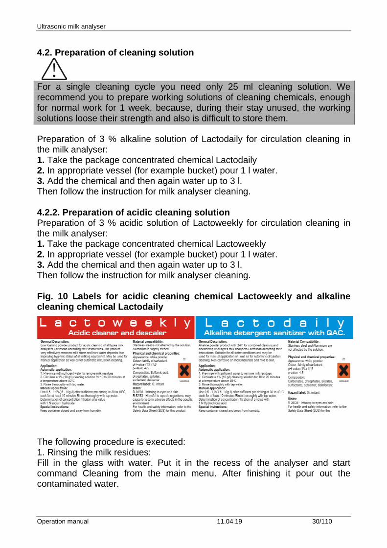
For a single cleaning cycle you need only 25 ml cleaning solution. We recommend you to prepare working solutions of cleaning chemicals, enough for normal work for 1 week, because, during their stay unused, the working solutions loose their strength and also is difficult to store them. Preparation of 3 % alkaline solution of Lactodaily for circulation cleaning in the milk analyser: 1. Take the package concentrated chemical Lactodaily 2. In appropriate vessel (for example bucket) pour 1 l water. 3. Add the chemical and then again water up to 3 l. Then follow the instruction for milk analyser cleaning. 4.2.2. Preparation of acidic cleaning solution Preparation of 3 % acidic solution of Lactoweekly for circulation cleaning in the milk analyser: 1. Take the package concentrated chemical Lactoweekly 2. In appropriate vessel (for example bucket) pour 1 l water. 3. Add the chemical and then again water up to 3 l. Then follow the instruction for milk analyser cleaning. Fig. 10 Labels for acidic cleaning chemical Lactoweekly and alkaline cleaning chemical Lactodaily
The following procedure is executed: 1. Rinsing the milk residues: Fill in the glass with water. Put it in the recess of the analyser and start command Cleaning from the main menu. After finishing it pour out the contaminated water.
Ultrasonic milk analyser
Operation manual 11.04.19 31/110
2. Cleaning with acidic solution Fill in the glass with warm (50-60 С) acidic cleaning solution. Put it in the recess of the analyser and start the command Cleaning from the main menu. After finishing it, pour out the contaminated liquid. 3. Rinsing with water Fill in the glass with water. Put it in the recess of the analyser and start command “Cleaning” from the main menu. After finishing it pour out the contaminated water. Now the device is ready for work.
Please, pay attention that, when the analysers gives a signal for need of cleaning 15 min after the last measurement of real milk samples or 55 min. after being powered and not used, cleaning is made ONLY with alkaline solution in concentration 1-3%. During the basic/final cleaning sequence is: alkaline solution – water – acidic solution - water
IMPORTANT THE MAIN REASON FOR MALFUNCTIONING OF THE
DEVICE IS THE BAD CLEANING OF THE SYSTEM AFTER MAKING ANALYSIS.
In case of malfunction due to the bad cleaning of the analyser your guarantee is not valid anymore and any
repair has to be paid.
Ultrasonic milk analyser
Operation manual 11.04.19 32/110
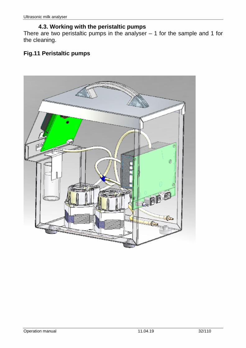
4.3. Working with the peristaltic pumps There are two peristaltic pumps in the analyser – 1 for the sample and 1 for the cleaning. Fig.11 Peristaltic pumps
Ultrasonic milk analyser
Operation manual 11.04.19 33/110
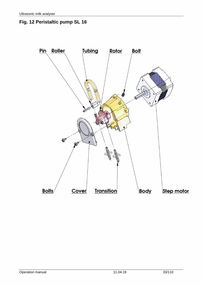
Fig. 12 Peristaltic pump SL 16
Ultrasonic milk analyser
Operation manual 11.04.19 34/110
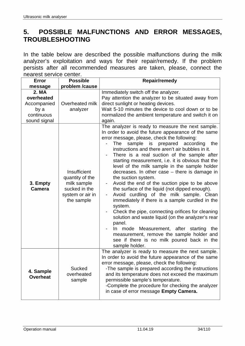
5. POSSIBLE MALFUNCTIONS AND ERROR MESSAGES, TROUBLESHOOTING In the table below are described the possible malfunctions during the milk analyzer’s exploitation and ways for their repair/remedy. If the problem persists after all recommended measures are taken, please, connect the nearest service center.
Error message
Possible problem /cause
Repair/remedy
2. MA overheated
Accompanied by a
continuous sound signal
Overheated milk analyzer
Immediately switch off the analyzer. Pay attention the analyzer to be situated away from direct sunlight or heating devices. Wait 5-10 minutes the device to cool down or to be normalized the ambient temperature and switch it on again.
3. Empty Camera
Insufficient quantity of the milk sample
sucked in the system or air in
the sample
The analyzer is ready to measure the next sample. In order to avoid the future appearance of the same error message, please, check the following:
- The sample is prepared according the instructions and there aren’t air bubbles in it.
- There is a real suction of the sample after starting measurement, i.e. it is obvious that the level of the milk sample in the sample holder decreases. In other case – there is damage in the suction system.
- Avoid the end of the suction pipe to be above the surface of the liquid (not dipped enough).
- Avoid curdling of the milk sample. Clean immediately if there is a sample curdled in the system.
- Check the pipe, connecting orifices for cleaning solution and waste liquid (on the analyzer’s rear panel.
- In mode Measurement, after starting the measurement, remove the sample holder and see if there is no milk poured back in the sample holder.
4. Sample Overheat
Sucked overheated
sample
The analyzer is ready to measure the next sample. In order to avoid the future appearance of the same error message, please, check the following:
-The sample is prepared according the instructions and its temperature does not exceed the maximum permissible sample’s temperature. -Complete the procedure for checking the analyzer in case of error message Empty Camera.
Ultrasonic milk analyser
Operation manual 11.04.19 35/110
6. MAKING CORRECTIONS AND RECALLIBRATION OF THE DEVICE In the process of work with the analyser there is a possibility the results to start differing between the data for some of the measuring parameters when measured with the milk analyzer and the corresponding reference method of analysis (Gerber for fat, Kjeldhal for proteins etc). In order to establish the possible discrepancy and to correct the readings of the milk analyser do the following:
6.1. Taking samples and preparation of samples for checking the accurracy of the milk analyser, making corrections and recalibration
This is a basic moment for the correct checking the accuracy of the analyser and for making correct and precise correction and calibration. It is accomplished according Appendix Sampling and preparation of samples for verification the accuracy of the milk analyzer, making corrections and recalibration.
6.2. Determination the type of the discrepancy:
6.2.1. Making measurements Make measurements with different samples (not less than 3) with known values of a separate parameter (for example fat content), determined by the known reference methods of analysis (for example Gerber's method for determination of fat content). For more accuracy it is recommended among these samples to be also such with values, close to the lowest and highest bounds for the measured parameters. Make 5-time measurement for each of the samples. Calculate the average value for each sample parameter, without taking into consideration the first measurement for each sample.
6.2.2. Analysing the measurement results Make comparison between the values of the parameter from the reference sample and measured with the analyser. Make analysis of the difference received. 6.2.2.1. If the received differences are relatively constant value for samples with different content of the analysed parameter, it is necessary to make correction.
Ultrasonic milk analyser
Operation manual 11.04.19 36/110
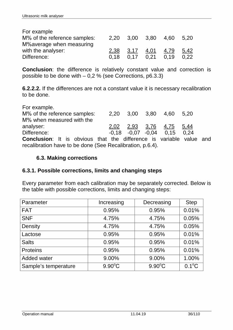
For example М% of the reference samples: 2,20 3,00 3,80 4,60 5,20 М%average when measuring with the analyser: 2,38 3,17 4,01 4,79 5,42 Difference: 0,18 0,17 0,21 0,19 0,22 Conclusion: the difference is relatively constant value and correction is possible to be done with – 0,2 % (see Corrections, p6.3.3)
6.2.2.2. If the differences are not a constant value it is necessary recalibration to be done. For example. М% of the reference samples: 2,20 3,00 3,80 4,60 5,20 М% when measured with the analyser: 2,02 2,93 3,76 4,75 5,44 Difference: -0,18 -0,07 -0,04 0,15 0,24 Conclusion: It is obvious that the difference is variable value and recalibration have to be done (See Recalibration, p.6.4).
6.3. Making corrections 6.3.1. Possible corrections, limits and changing steps Every parameter from each calibration may be separately corrected. Below is the table with possible corrections, limits and changing steps: Parameter Increasing Decreasing Step FAT 0.95% 0.95% 0.01% SNF 4.75% 4.75% 0.05% Density 4.75% 4.75% 0.05% Lactose 0.95% 0.95% 0.01% Salts 0.95% 0.95% 0.01% Proteins 0.95% 0.95% 0.01% Added water 9.00% 9.00% 1.00% Sample’s temperature 9.90oС 9.90oС 0.1oС
Ultrasonic milk analyser
Operation manual 11.04.19 37/110
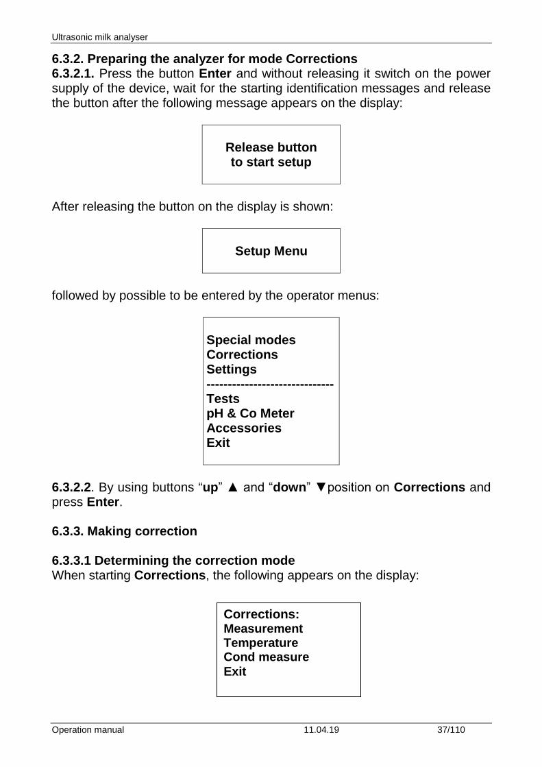
6.3.2. Preparing the analyzer for mode Corrections 6.3.2.1. Press the button Enter and without releasing it switch on the power supply of the device, wait for the starting identification messages and release the button after the following message appears on the display:
Release button to start setup
After releasing the button on the display is shown:
Setup Menu
followed by possible to be entered by the operator menus:
Special modes Corrections Settings ------------------------------ Tests pH & Co Meter Accessories Exit
6.3.2.2. By using buttons “up” ▲ and “down” ▼position on Corrections and press Enter. 6.3.3. Making correction 6.3.3.1 Determining the correction mode When starting Corrections, the following appears on the display:
Corrections: Measurement Temperature Cond measure Exit
Ultrasonic milk analyser
Operation manual 11.04.19 38/110
Position on Measurement and press Enter. By using buttons “up”▲ and ”down”▼position on the corresponding calibration (for example Correction 1 – cow) and press Enter.
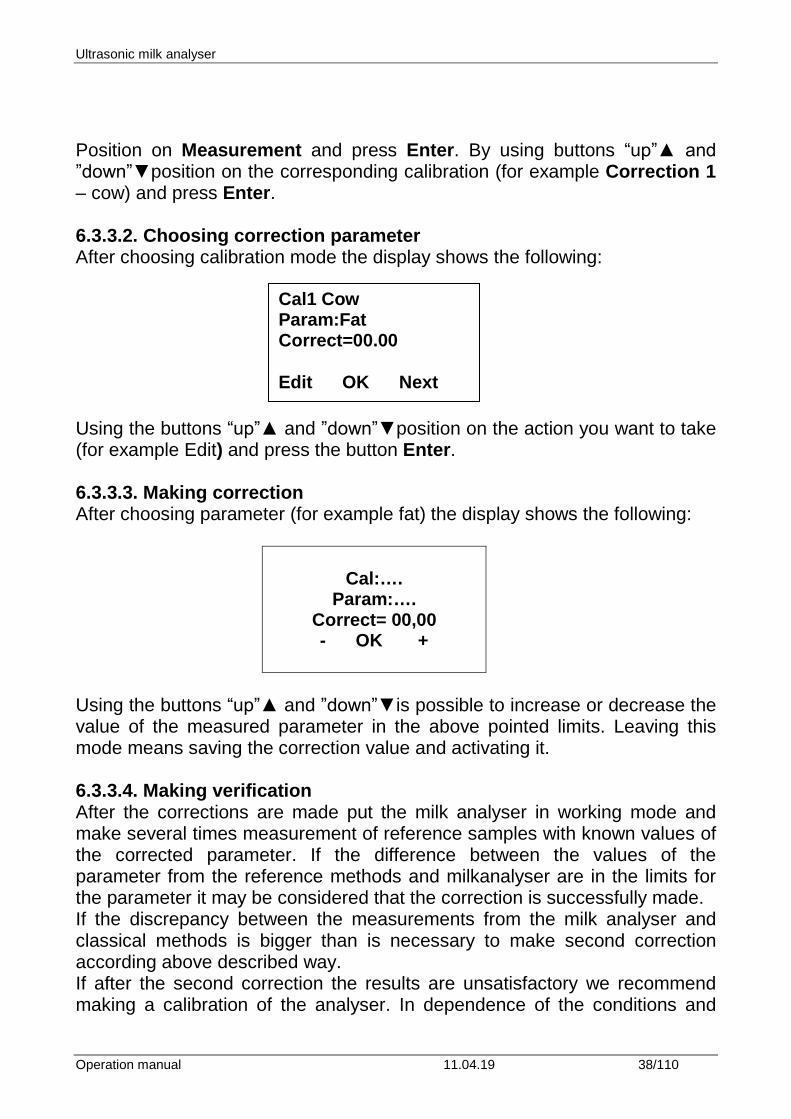
6.3.3.2. Choosing correction parameter After choosing calibration mode the display shows the following: Using the buttons “up”▲ and ”down”▼position on the action you want to take (for example Edit) and press the button Enter.
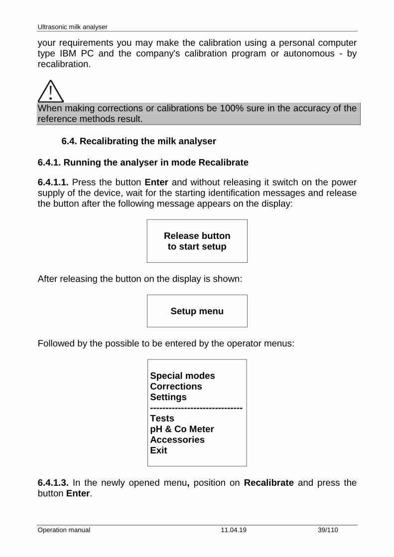
6.3.3.3. Making correction After choosing parameter (for example fat) the display shows the following:
Cal:….
Param:…. Correct= 00,00 - OK +
Using the buttons “up”▲ and ”down”▼is possible to increase or decrease the value of the measured parameter in the above pointed limits. Leaving this mode means saving the correction value and activating it.
6.3.3.4. Making verification After the corrections are made put the milk analyser in working mode and make several times measurement of reference samples with known values of the corrected parameter. If the difference between the values of the parameter from the reference methods and milkanalyser are in the limits for the parameter it may be considered that the correction is successfully made. If the discrepancy between the measurements from the milk analyser and classical methods is bigger than is necessary to make second correction according above described way. If after the second correction the results are unsatisfactory we recommend making a calibration of the analyser. In dependence of the conditions and
Cal1 Cow Param:Fat Correct=00.00 Edit OK Next
Ultrasonic milk analyser
Operation manual 11.04.19 39/110
your requirements you may make the calibration using a personal computer type IBM PC and the company's calibration program or autonomous - by recalibration.
When making corrections or calibrations be 100% sure in the accuracy of the reference methods result.
6.4. Recalibrating the milk analyser
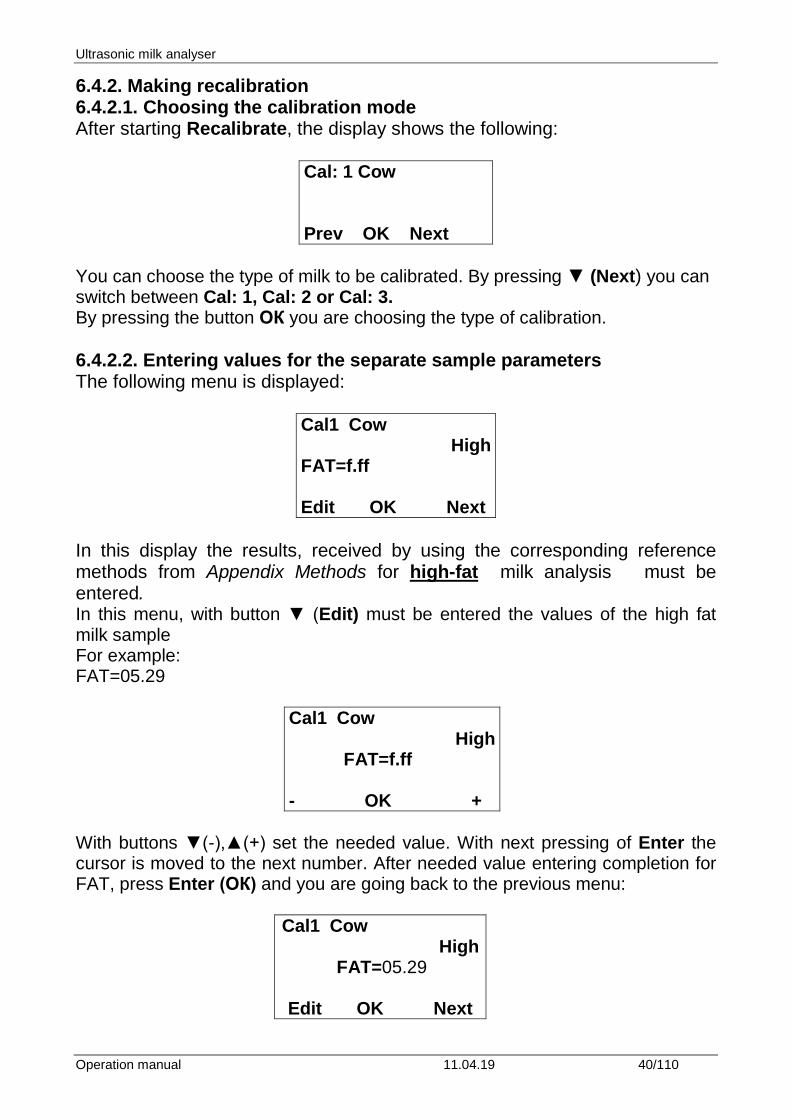
6.4.1. Running the analyser in mode Recalibrate 6.4.1.1. Press the button Enter and without releasing it switch on the power supply of the device, wait for the starting identification messages and release the button after the following message appears on the display:
Release button to start setup
After releasing the button on the display is shown:
Setup menu
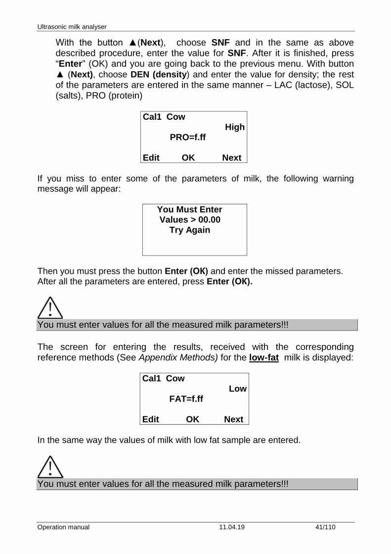
Followed by the possible to be entered by the operator menus:
Special modes Corrections Settings ------------------------------ Tests pH & Co Meter Accessories Exit
6.4.1.3. In the newly opened menu, position on Recalibrate and press the button Enter.
Ultrasonic milk analyser
Operation manual 11.04.19 40/110
6.4.2. Making recalibration 6.4.2.1. Choosing the calibration mode After starting Recalibrate, the display shows the following:
Cal: 1 Cow Prev OK Next
You can choose the type of milk to be calibrated. By pressing ▼ (Next) you can switch between Cal: 1, Cal: 2 or Cal: 3. By pressing the button ОК you are choosing the type of calibration. 6.4.2.2. Entering values for the separate sample parameters The following menu is displayed:
Cal1 Cow High
FAT=f.ff Edit OK Next
In this display the results, received by using the corresponding reference methods from Appendix Methods for high-fat milk analysis must be entered. In this menu, with button ▼ (Edit) must be entered the values of the high fat milk sample For example: FAT=05.29
Cal1 Cow High
FAT=f.ff - OK +
With buttons ▼(-),▲(+) set the needed value. With next pressing of Enter the cursor is moved to the next number. After needed value entering completion for FAT, press Enter (ОК) and you are going back to the previous menu:
Cal1 Cow High
FAT=05.29 Edit OK Next
Ultrasonic milk analyser
Operation manual 11.04.19 41/110
With the button ▲(Next), choose SNF and in the same as above described procedure, enter the value for SNF. After it is finished, press “Enter” (OK) and you are going back to the previous menu. With button ▲ (Next), choose DEN (density) and enter the value for density; the rest of the parameters are entered in the same manner – LAC (lactose), SOL (salts), PRO (protein)
Cal1 Cow High
PRO=f.ff Edit OK Next
If you miss to enter some of the parameters of milk, the following warning message will appear:
You Must Enter Values > 00.00 Try Again
Then you must press the button Enter (ОК) and enter the missed parameters. After all the parameters are entered, press Enter (ОК).
You must enter values for all the measured milk parameters!!! The screen for entering the results, received with the corresponding reference methods (See Appendix Methods) for the low-fat milk is displayed:
Cal1 Cow Low
FAT=f.ff Edit OK Next
In the same way the values of milk with low fat sample are entered.
You must enter values for all the measured milk parameters!!!
Ultrasonic milk analyser
Operation manual 11.04.19 42/110
In other case the calibration will not be correct. 6.4.2.3. Making recalibration with the available samples After entering the values for the separate parameters of the sample, pressing Enter (OK) will display the following menu:
Cal: Cow
Put sample High 5 times
which reminds us to put 5 times the sample with high FAT.
The sample has to be with temperature in the boundaries 15-25°С. Before each milk measurement stir 2-3 times the milk sample by pouring it from one vessel to another. The needed quantity is poured in the sample-holder and it is put in the recess of the analyser. Start the measurement by pressing the button Enter. The sample is sucked. Appears the following menu:
Cal: Cow Put sample: High 5 times Temp=….
After the sample is measured, appears the following menu:
Cow High N1=….. 2=……. Cal meas=1/5
which reminds us to make the next measurement. Before each measurement the milk is stirred by pouring it 2-3 times from vessel to vessel. Continue the procedure till the 5th measurement.
Ultrasonic milk analyser
Operation manual 11.04.19 43/110
After 5th measurement completion automatically appears the menu, which reminds us to place the Low fat milk sample:
Cal: Cow Put Sampl: Low 5 times
Stir 2-3 times the milk sample before each measurement by pouring it from one vessel to another. The needed quantity is poured in the sample-holder and it is put in the recess of the analyser. Start the measurement by pressing the button Enter. The sample is sucked. Appears the following menu: Make 5 times measurement of the low FAT sample. After 5th measurement completion automatically appears the menu:
Cal: Cow Put sample: Water 5 times
Which reminds for 5-times water measurement. After the 5th measurement appears the menu:
Recalibrated Power Off-On
This means that the calibration was completed successfully and the analyzer is recalibrated for cow milk, marked as “Cal: Cow”. Switch off the power supply of the device and switch it on again. The device is ready to work with the new calibration. Next time when the analyser is switched on, it will be ready for work with those milk types it was just calibrated with. If calibration with another milk type is needed, do not forget to change the calibration number for the new type of milk. Calibration for Sheep milk will be saved as second calibration, UHT – as third. This sequence may not be followed and calibrations can be saved in whichever order is needed. Calibration can be done with different liquid dairy products using 2 representative samples. Checking the calibration 1. Switch on the calibrated device.
Ultrasonic milk analyser
Operation manual 11.04.19 44/110
2. Make sure it shows the same serial number as this already calibrated. For checking, use the third sample with medium FAT content. 3. Measure the milk 5 times in the mode you’ve calibrated it. In case that the device is not connected towards printer write down the results. 4. Ignore the first two results. The rest three could not differ more than 0,05% FAT, 0,07% SNF, 0,7% Density one from another
Ultrasonic milk analyser
Operation manual 11.04.19 45/110
7. STARTING THE DEVICE IN A SERVICE TEST/SETUP OPERATIONAL MODE. MENUS DESIGNATION 7.1. Starting the device in a service Test/Setup operational mode. In order to start the Setup of the device the operator has to press the button Enter and without releasing it to switch on the power supply of the device, to wait for the starting identification messages and to release the button after the following message appears on the display:
Release button to start setup
After releasing the button on the display is shown:
MA Setup
Followed by possible to be entered by the operator menus:
Special modes Corrections Settings ------------------------------ Tests pH & Co Meter Exit
You may move in the menus by using buttons “up” ▲ and “down” ▼. If by pressing the button Enter you choose a menu, each menu offers new points/submenus. When Exit is chosen the device leaves the Setup mode and returns to normal work. 7.2. Menus Function: 7.2.1. Special modes.
Ultrasonic milk analyser
Operation manual 11.04.19 46/110
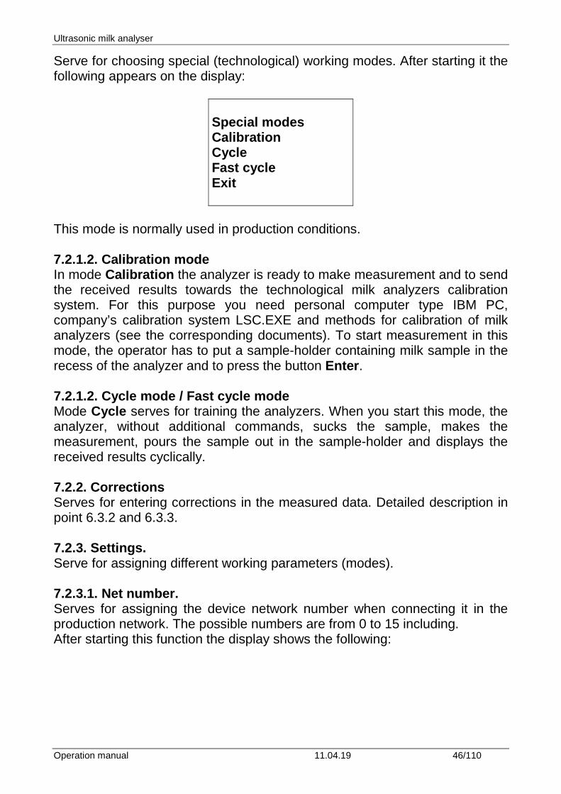
Serve for choosing special (technological) working modes. After starting it the following appears on the display:
Special modes Calibration Cycle Fast cycle Exit
This mode is normally used in production conditions. 7.2.1.2. Calibration mode In mode Calibration the analyzer is ready to make measurement and to send the received results towards the technological milk analyzers calibration system. For this purpose you need personal computer type IBM PC, company’s calibration system LSC.EXE and methods for calibration of milk analyzers (see the corresponding documents). To start measurement in this mode, the operator has to put a sample-holder containing milk sample in the recess of the analyzer and to press the button Enter. 7.2.1.2. Cycle mode / Fast cycle mode Mode Cycle serves for training the analyzers. When you start this mode, the analyzer, without additional commands, sucks the sample, makes the measurement, pours the sample out in the sample-holder and displays the received results cyclically. 7.2.2. Corrections Serves for entering corrections in the measured data. Detailed description in point 6.3.2 and 6.3.3. 7.2.3. Settings. Serve for assigning different working parameters (modes). 7.2.3.1. Net number. Serves for assigning the device network number when connecting it in the production network. The possible numbers are from 0 to 15 including. After starting this function the display shows the following:
Ultrasonic milk analyser
Operation manual 11.04.19 47/110
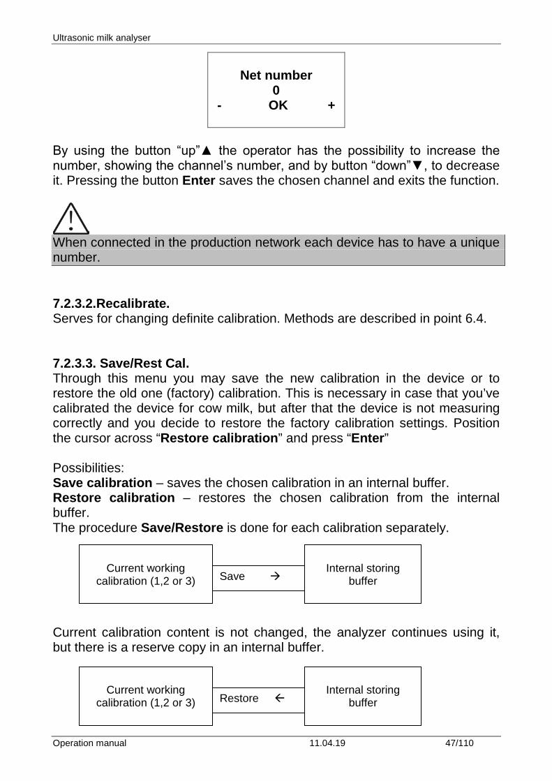
Net number
0 - OK +
By using the button “up”▲ the operator has the possibility to increase the number, showing the channel’s number, and by button “down”▼, to decrease it. Pressing the button Enter saves the chosen channel and exits the function.
When connected in the production network each device has to have a unique number. 7.2.3.2.Recalibrate. Serves for changing definite calibration. Methods are described in point 6.4. 7.2.3.3. Save/Rest Cal. Through this menu you may save the new calibration in the device or to restore the old one (factory) calibration. This is necessary in case that you’ve calibrated the device for cow milk, but after that the device is not measuring correctly and you decide to restore the factory calibration settings. Position the cursor across “Restore calibration” and press “Enter” Possibilities: Save calibration – saves the chosen calibration in an internal buffer. Restore calibration – restores the chosen calibration from the internal buffer. The procedure Save/Restore is done for each calibration separately.
Current calibration content is not changed, the analyzer continues using it, but there is a reserve copy in an internal buffer.
Current working
calibration (1,2 or 3) Save
Internal storing
buffer
Current working
calibration (1,2 or 3) Restore
Internal storing
buffer
Ultrasonic milk analyser
Operation manual 11.04.19 48/110
The current calibration is replaced with the calibration from the internal buffer and the analyzer starts working with it. The content of the internal buffer is not changed.
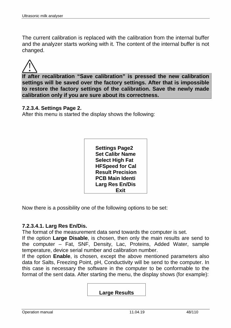
If after recalibration “Save calibration” is pressed the new calibration settings will be saved over the factory settings. After that is impossible to restore the factory settings of the calibration. Save the newly made calibration only if you are sure about its correctness. 7.2.3.4. Settings Page 2. After this menu is started the display shows the following:
Settings Page2 Set Calibr Name Select High Fat HFSpeed for Cal Result Precision PCB Main Identi Larg Res En/Dis
Exit Now there is a possibility one of the following options to be set: 7.2.3.4.1. Larg Res En/Dis. The format of the measurement data send towards the computer is set. If the option Large Disable, is chosen, then only the main results are send to the computer – Fat, SNF, Density, Lac, Proteins, Added Water, sample temperature, device serial number and calibration number. If the option Enable, is chosen, except the above mentioned parameters also data for Salts, Freezing Point, pH, Conductivity will be send to the computer. In this case is necessary the software in the computer to be conformable to the format of the sent data. After starting the menu, the display shows (for example):
Large Results
Ultrasonic milk analyser
Operation manual 11.04.19 49/110
No
No OK Yes
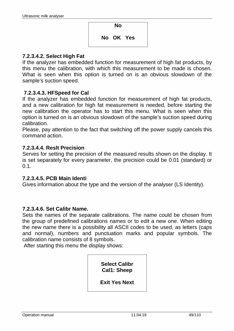
7.2.3.4.2. Select High Fat If the analyzer has embedded function for measurement of high fat products, by this menu the calibration, with which this measurement to be made is chosen. What is seen when this option is turned on is an obvious slowdown of the sample’s suction speed. 7.2.3.4.3. HFSpeed for Cal If the analyzer has embedded function for measurement of high fat products, and a new calibration for high fat measurement is needed, before starting the new calibration the operator has to start this menu. What is seen when this option is turned on is an obvious slowdown of the sample’s suction speed during calibration. Please, pay attention to the fact that switching off the power supply cancels this command action. 7.2.3.4.4. Reslt Precision Serves for setting the precision of the measured results shown on the display. It is set separately for every parameter, the precision could be 0.01 (standard) or 0.1. 7.2.3.4.5. PCB Main Identi Gives information about the type and the version of the analyser (LS Identity). 7.2.3.4.6. Set Calibr Name. Sets the names of the separate calibrations. The name could be chosen from the group of predefined calibrations names or to edit a new one. When editing the new name there is a possibility all ASCII codes to be used, as letters (caps and normal), numbers and punctuation marks and popular symbols. The calibration name consists of 8 symbols. After starting this menu the display shows:
Select Calibr Cal1: Sheep
Exit Yes Next
Ultrasonic milk analyser
Operation manual 11.04.19 50/110
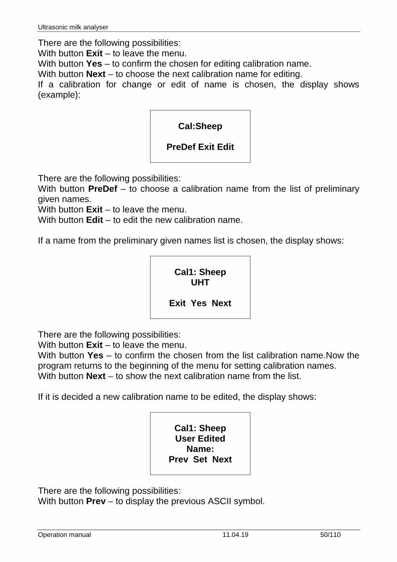
There are the following possibilities: With button Exit – to leave the menu. With button Yes – to confirm the chosen for editing calibration name. With button Next – to choose the next calibration name for editing. If a calibration for change or edit of name is chosen, the display shows (example):
Cal:Sheep
PreDef Exit Edit
There are the following possibilities: With button PreDef – to choose a calibration name from the list of preliminary given names. With button Exit – to leave the menu. With button Edit – to edit the new calibration name. If a name from the preliminary given names list is chosen, the display shows:
Cal1: Sheep
UHT
Exit Yes Next
There are the following possibilities: With button Exit – to leave the menu. With button Yes – to confirm the chosen from the list calibration name.Now the program returns to the beginning of the menu for setting calibration names. With button Next – to show the next calibration name from the list. If it is decided a new calibration name to be edited, the display shows:
Cal1: Sheep User Edited
Name: Prev Set Next
There are the following possibilities: With button Prev – to display the previous ASCII symbol.
Ultrasonic milk analyser
Operation manual 11.04.19 51/110
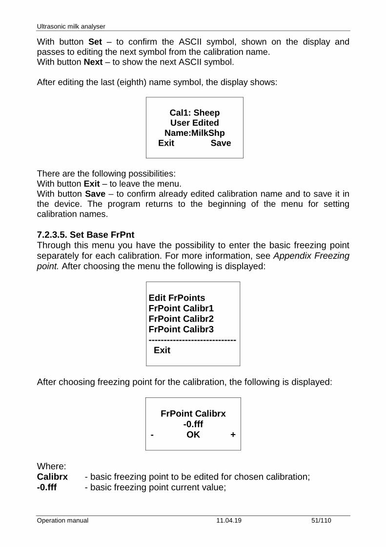
With button Set – to confirm the ASCII symbol, shown on the display and passes to editing the next symbol from the calibration name. With button Next – to show the next ASCII symbol. After editing the last (eighth) name symbol, the display shows:
Cal1: Sheep User Edited
Name:MilkShp Exit Save
There are the following possibilities: With button Exit – to leave the menu. With button Save – to confirm already edited calibration name and to save it in the device. The program returns to the beginning of the menu for setting calibration names. 7.2.3.5. Set Base FrPnt Through this menu you have the possibility to enter the basic freezing point separately for each calibration. For more information, see Appendix Freezing point. After choosing the menu the following is displayed:
Edit FrPoints FrPoint Calibr1 FrPoint Calibr2 FrPoint Calibr3 ----------------------------- Exit
After choosing freezing point for the calibration, the following is displayed:
FrPoint Calibrx
-0.fff - OK +
Where: Calibrx - basic freezing point to be edited for chosen calibration; -0.fff - basic freezing point current value;
Ultrasonic milk analyser
Operation manual 11.04.19 52/110
By pressing the buttons: “up”▲ - you may increase the absolute value of the freezing point; ”down”▼ - you may decrease the absolute value of the freezing point; “Enter” - saves the edited value and exits the menu; 7.2.4. Tests. Start different tests. Possibilities: 7.2.4.1. Test pump. Starts pump’s test. The number of the completed suction/display cycles is indicated. 7.2.4.2. Ultrasound. Test for the ultrasonic system. Used in production conditions. 7.2.4.3. Set Amplitude. Serves for ultrasound amplitude adjustment. It is used under production conditions or by the customer (after sensor change) according the instructions in the document SetCell.pdf. 7.2.4.4. RS232 COMPort 7.2.4.5. Keypad 7.2.4.6. USB Flash
Please, use this menu only after reading the above pointed document SetCell.pdf 7.2.5. pH meter & Co meter Ph and conductivity measuring are additional possibilities for the analyser and are optional. Their usage is described in Appendices PH Measurement and Conductivity Measurement.
Ultrasonic milk analyser
Operation manual 11.04.19 53/110
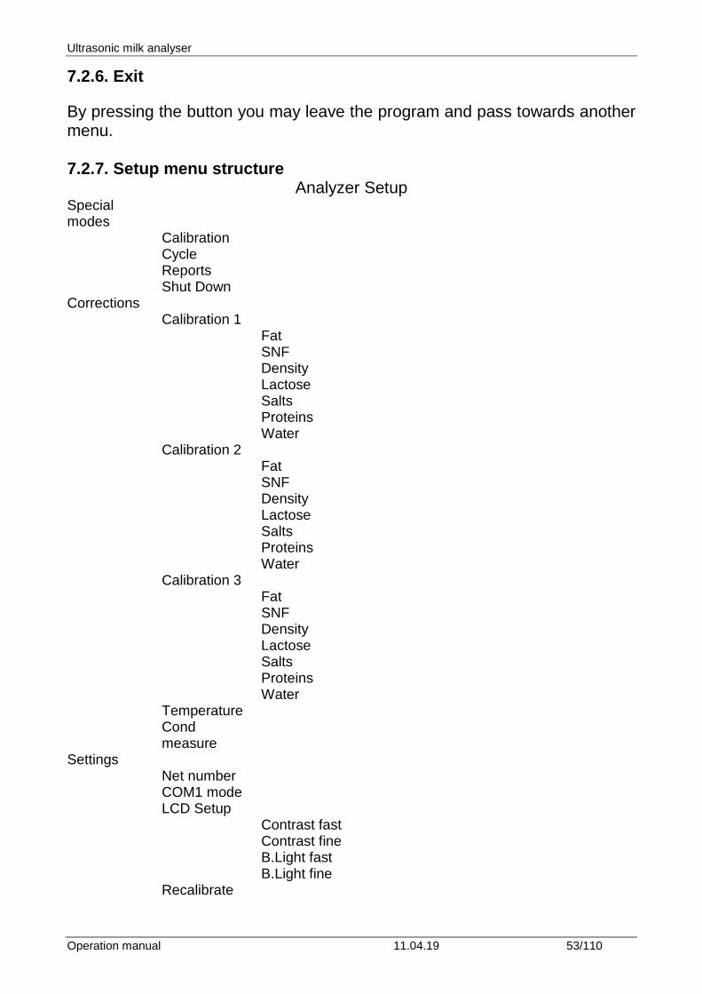
7.2.6. Exit By pressing the button you may leave the program and pass towards another menu. 7.2.7. Setup menu structure
Analyzer Setup Special modes
Calibration Cycle Reports Shut Down
Corrections Calibration 1 Fat
SNF Density Lactose Salts Proteins Water
Calibration 2 Fat
SNF Density Lactose Salts Proteins Water
Calibration 3 Fat
SNF Density Lactose Salts Proteins Water
Temperature Cond
measure
Settings Net number
COM1 mode LCD Setup
Contrast fast Contrast fine B.Light fast B.Light fine
Recalibrate
Ultrasonic milk analyser
Operation manual 11.04.19 54/110
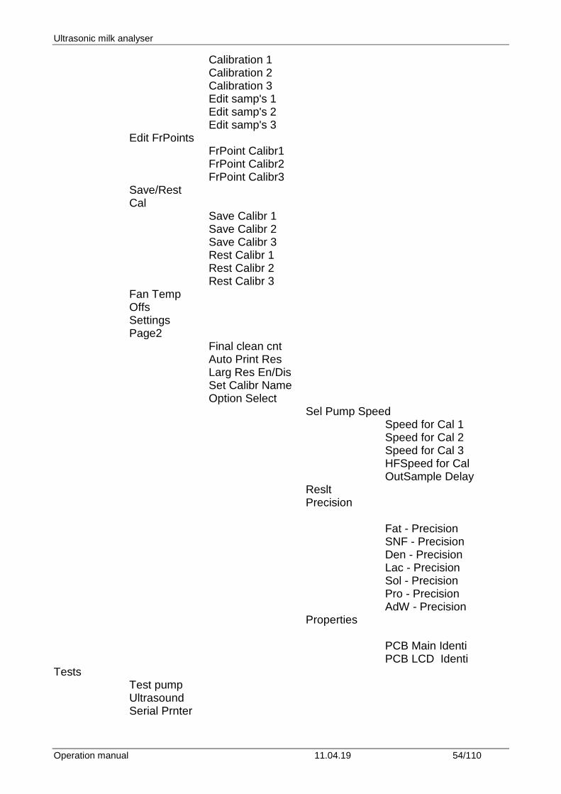
Calibration 1 Calibration 2 Calibration 3 Edit samp's 1 Edit samp's 2 Edit samp's 3
Edit FrPoints FrPoint Calibr1
FrPoint Calibr2 FrPoint Calibr3
Save/Rest Cal
Save Calibr 1 Save Calibr 2 Save Calibr 3 Rest Calibr 1 Rest Calibr 2 Rest Calibr 3
Fan Temp Offs Settings Page2
Final clean cnt Auto Print Res Larg Res En/Dis Set Calibr Name Option Select
Sel Pump Speed Speed for Cal 1
Speed for Cal 2 Speed for Cal 3 HFSpeed for Cal OutSample Delay
Reslt Precision
Fat - Precision SNF - Precision Den - Precision Lac - Precision Sol - Precision Pro - Precision AdW - Precision
Properties
PCB Main Identi PCB LCD Identi
Tests Test pump
Ultrasound Serial Prnter
Ultrasonic milk analyser
Operation manual 11.04.19 55/110
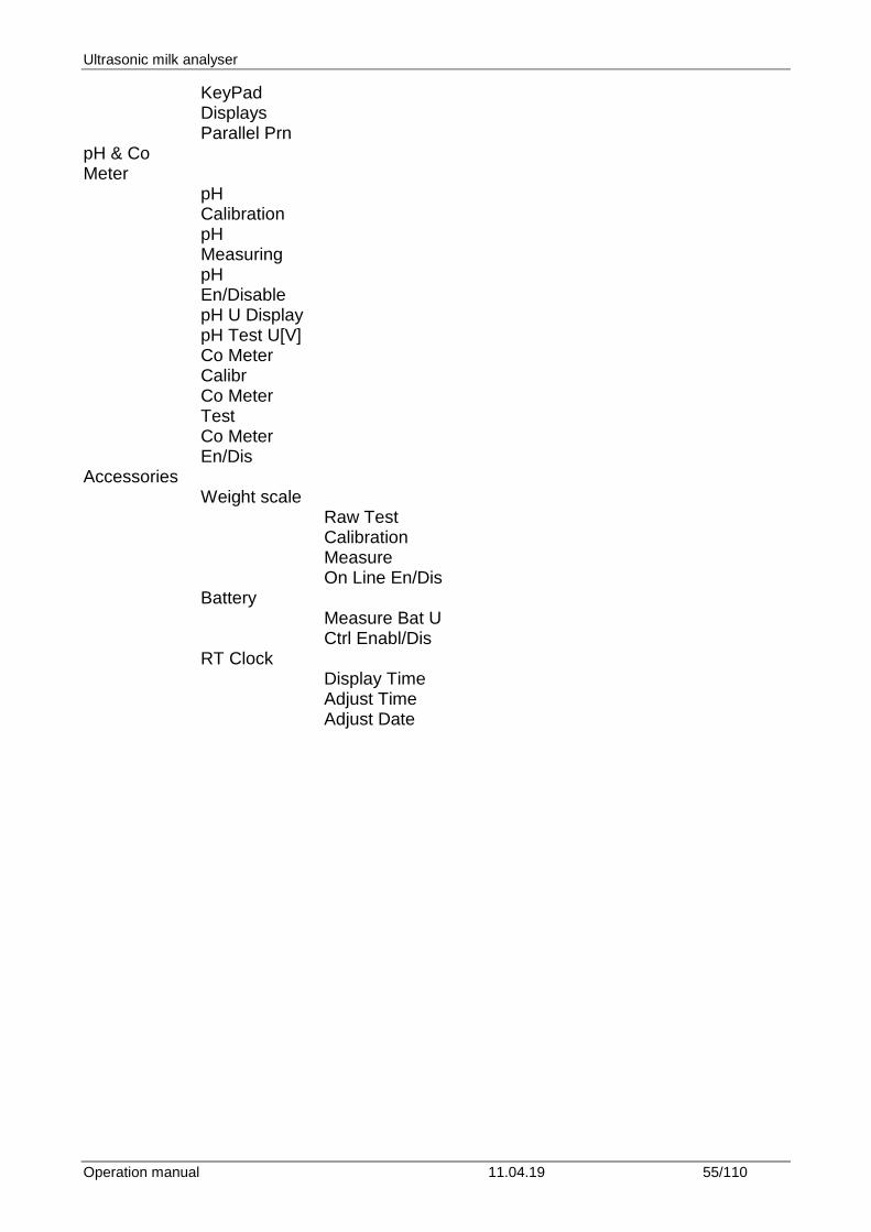
KeyPad Displays Parallel Prn
pH & Co Meter
pH Calibration pH Measuring pH En/Disable pH U Display pH Test U[V] Co Meter Calibr Co Meter Test Co Meter En/Dis
Accessories Weight scale Raw Test
Calibration Measure On Line En/Dis
Battery Measure Bat U
Ctrl Enabl/Dis
RT Clock Display Time
Adjust Time Adjust Date
Ultrasonic milk analyser
Operation manual 11.04.19 56/110
8. ENTERING DATA WITH THE KEYPAD AND PRINTING OUT THE RESULTS
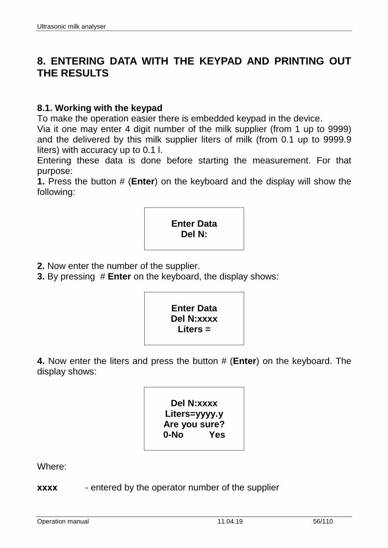
8.1. Working with the keypad To make the operation easier there is embedded keypad in the device. Via it one may enter 4 digit number of the milk supplier (from 1 up to 9999) and the delivered by this milk supplier liters of milk (from 0.1 up to 9999.9 liters) with accuracy up to 0.1 l. Entering these data is done before starting the measurement. For that purpose: 1. Press the button # (Enter) on the keyboard and the display will show the following:
Enter Data
Del N:
2. Now enter the number of the supplier. 3. By pressing # Enter on the keyboard, the display shows:
Enter Data Del N:xxxx
Liters =
4. Now enter the liters and press the button # (Enter) on the keyboard. The display shows:
Del N:xxxx
Liters=yyyy.y Are you sure? 0-No Yes
Where: хxxx - entered by the operator number of the supplier
Ultrasonic milk analyser
Operation manual 11.04.19 57/110
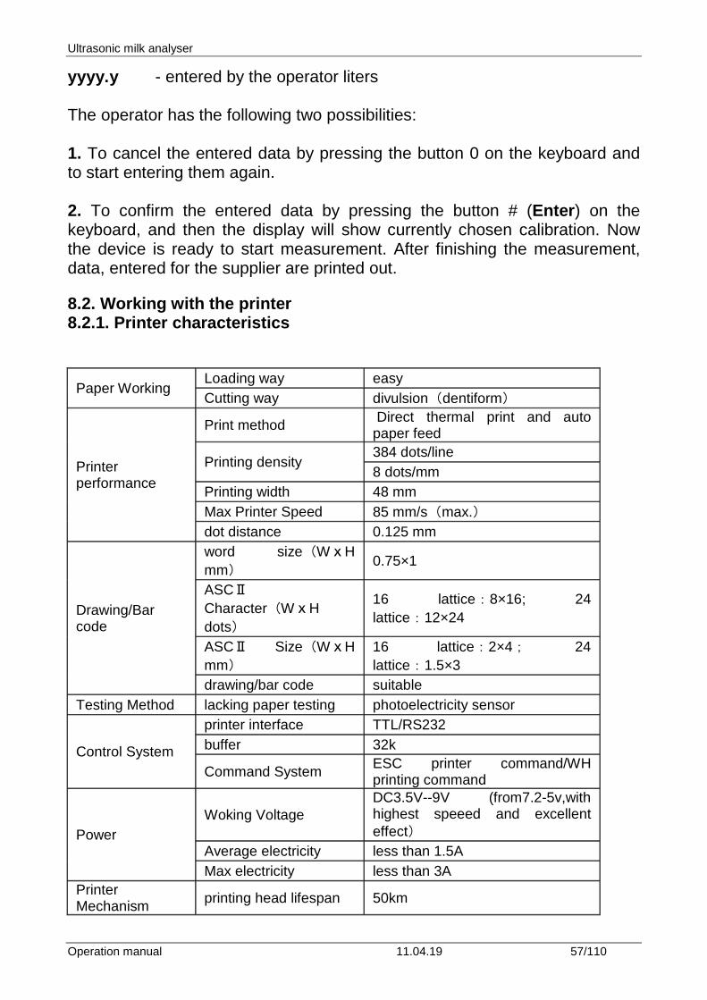
yyyy.y - entered by the operator liters The operator has the following two possibilities: 1. To cancel the entered data by pressing the button 0 on the keyboard and to start entering them again. 2. To confirm the entered data by pressing the button # (Enter) on the keyboard, and then the display will show currently chosen calibration. Now the device is ready to start measurement. After finishing the measurement, data, entered for the supplier are printed out. 8.2. Working with the printer 8.2.1. Printer characteristics
Paper Working Loading way easy Cutting way divulsion(dentiform)
Printer performance
Print method Direct thermal print and auto paper feed
Printing density 384 dots/line 8 dots/mm
Printing width 48 mm Max Printer Speed 85 mm/s(max.) dot distance 0.125 mm
Drawing/Bar code
word size(WⅹH mm) 0.75×1
ASCⅡ Character(WⅹH dots)
16 lattice:8×16; 24 lattice:12×24
ASCⅡ Size(WⅹH mm)
16 lattice:2×4; 24 lattice:1.5×3
drawing/bar code suitable Testing Method lacking paper testing photoelectricity sensor
Control System
printer interface TTL/RS232 buffer 32k
Command System ESC printer command/WH printing command
Power Woking Voltage
DC3.5V--9V (from7.2-5v,with highest speeed and excellent effect)
Average electricity less than 1.5A Max electricity less than 3A
Printer Mechanism printing head lifespan 50km
Ultrasonic milk analyser
Operation manual 11.04.19 58/110
Paper
paper item thermal paper paper width 58mm papaer thickness 65±5um diameter of paper roll 30mm
Physics Specification
Environment adaptability
0~55℃;-20~55℃ 10~90%RH
Storage temperature –25~70℃ 10~90%RH
Dimension (WⅹHⅹD mm) 103mm×57mm×57mm
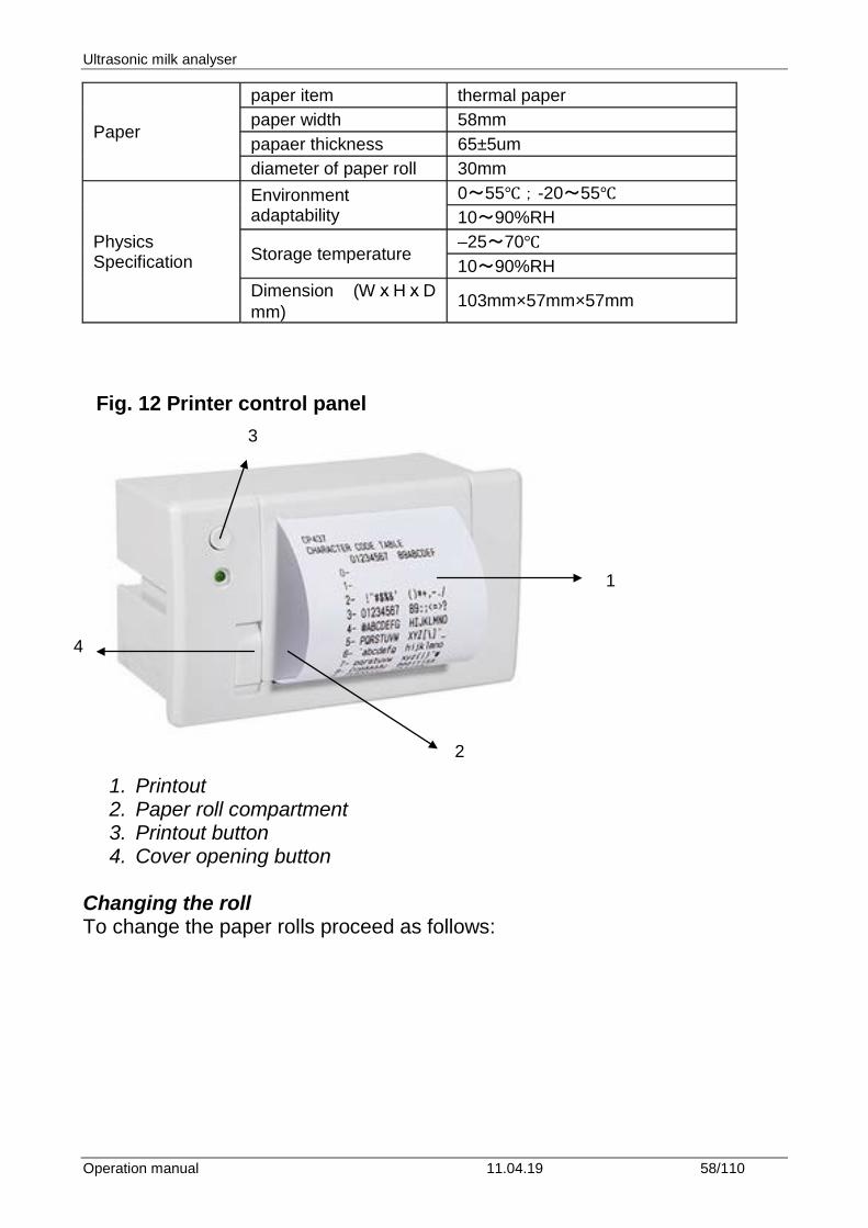
Fig. 12 Printer control panel
1. Printout 2. Paper roll compartment 3. Printout button 4. Cover opening button
Changing the roll To change the paper rolls proceed as follows:
4
2
3
1
Ultrasonic milk analyser
Operation manual 11.04.19 59/110
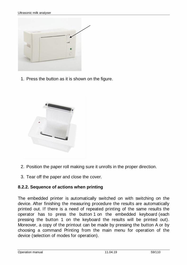
1. Press the button as it is shown on the figure.
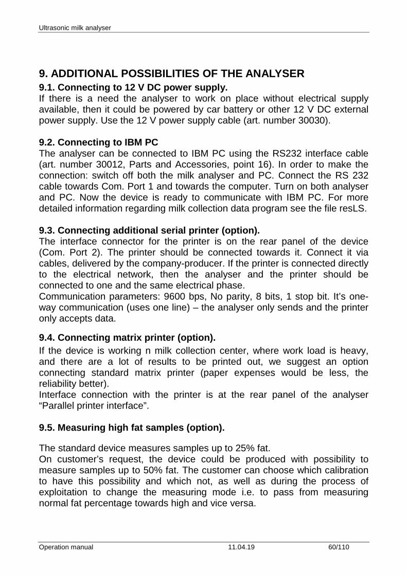
2. Position the paper roll making sure it unrolls in the proper direction.
3. Tear off the paper and close the cover.
8.2.2. Sequence of actions when printing
The embedded printer is automatically switched on with switching on the device. After finishing the measuring procedure the results are automatically printed out. If there is a need of repeated printing of the same results the operator has to press the button 1 on the embedded keyboard (each pressing the button 1 on the keyboard the results will be printed out). Moreover, a copy of the printout can be made by pressing the button A or by choosing a command Printing from the main menu for operation of the device (selection of modes for operation).
Ultrasonic milk analyser
Operation manual 11.04.19 60/110
9. ADDITIONAL POSSIBILITIES OF THE ANALYSER 9.1. Connecting to 12 V DC power supply. If there is a need the analyser to work on place without electrical supply available, then it could be powered by car battery or other 12 V DC external power supply. Use the 12 V power supply cable (art. number 30030). 9.2. Connecting to IBM PC The analyser can be connected to IBM PC using the RS232 interface cable (art. number 30012, Parts and Accessories, point 16). In order to make the connection: switch off both the milk analyser and PC. Connect the RS 232 cable towards Com. Port 1 and towards the computer. Turn on both analyser and PC. Now the device is ready to communicate with IBM PC. For more detailed information regarding milk collection data program see the file resLS. 9.3. Connecting additional serial printer (option). The interface connector for the printer is on the rear panel of the device (Com. Port 2). The printer should be connected towards it. Connect it via cables, delivered by the company-producer. If the printer is connected directly to the electrical network, then the analyser and the printer should be connected to one and the same electrical phase. Communication parameters: 9600 bps, No parity, 8 bits, 1 stop bit. It’s one-way communication (uses one line) – the analyser only sends and the printer only accepts data.
9.4. Connecting matrix printer (option). If the device is working n milk collection center, where work load is heavy, and there are a lot of results to be printed out, we suggest an option connecting standard matrix printer (paper expenses would be less, the reliability better). Interface connection with the printer is at the rear panel of the analyser “Parallel printer interface”. 9.5. Measuring high fat samples (option). The standard device measures samples up to 25% fat. On customer’s request, the device could be produced with possibility to measure samples up to 50% fat. The customer can choose which calibration to have this possibility and which not, as well as during the process of exploitation to change the measuring mode i.e. to pass from measuring normal fat percentage towards high and vice versa.
Ultrasonic milk analyser
Operation manual 11.04.19 61/110
What the operator sees during these passes is the difference in the speed of sucking the sample. For that purpose, the high-fat sample has to be preliminary heated up to 30С +- 3С. To choose the mode, follow the sequence below: Setup->Settings->Settings Page2->Option Select->SelPumpSpeed->Speed for Cal x After which the display shows:
Calibr x Pump Speed Normal OK HiFat
By pressing the correspondent buttons the operator can choose the type of measurement and to exit the menu. When changing the type of measurement on a calibration is necessary a new calibration of the device on the new speed to be done. When calibrating measuring high fat sample, before starting the calibration procedure, the operator has to choose from the menu: Setup->Settings->Settings Page2->Option Select->SelPumpSpeed-> HFSpeed for Cal By which the device passes in a mode of measuring high fat samples. This calibration mode is active till the power supply of the device is switched off i.e. it has to be always set if the device will be calibrated for high fat measurement. 9.6. Working with embedded accumulator (option). On customers’ request accumulator could be embedded in the milk analyser. In this way it could work independently on the electrical network. In this case the Power switch on the rear panel of the analyser serves for close / open the electric circuit of the outer power supply. After closing the circuit, in order to start the analyser, the operator has to press the Start button on the front panel of the analyser. Switching off the analyser could be done on one of the following ways: Through the analyser – by switching the Power button on the rear panel of the analyser. Through the software – by using the option Shut Down from the Calibration and Working mode menus.
Ultrasonic milk analyser
Operation manual 11.04.19 62/110
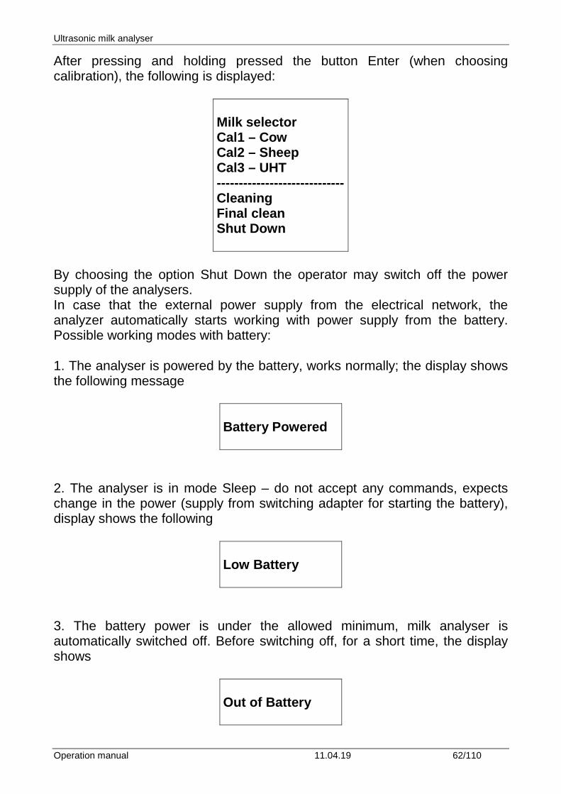
After pressing and holding pressed the button Enter (when choosing calibration), the following is displayed:
Milk selector Cal1 – Cow Cal2 – Sheep Cal3 – UHT ----------------------------- Cleaning Final clean Shut Down
By choosing the option Shut Down the operator may switch off the power supply of the analysers. In case that the external power supply from the electrical network, the analyzer automatically starts working with power supply from the battery. Possible working modes with battery: 1. The analyser is powered by the battery, works normally; the display shows the following message
Battery Powered
2. The analyser is in mode Sleep – do not accept any commands, expects change in the power (supply from switching adapter for starting the battery), display shows the following
Low Battery
3. The battery power is under the allowed minimum, milk analyser is automatically switched off. Before switching off, for a short time, the display shows
Out of Battery
Ultrasonic milk analyser
Operation manual 11.04.19 63/110
9.7. Automatic weighting the milk with scales (option). Scales could be connected towards the milk analyser, which to be used for weighting the delivered milk before measuring its parameters. For using the scale the operator has to follow up the two procedures:
- Preparation for work and checking the scales - Weighting delivered milk
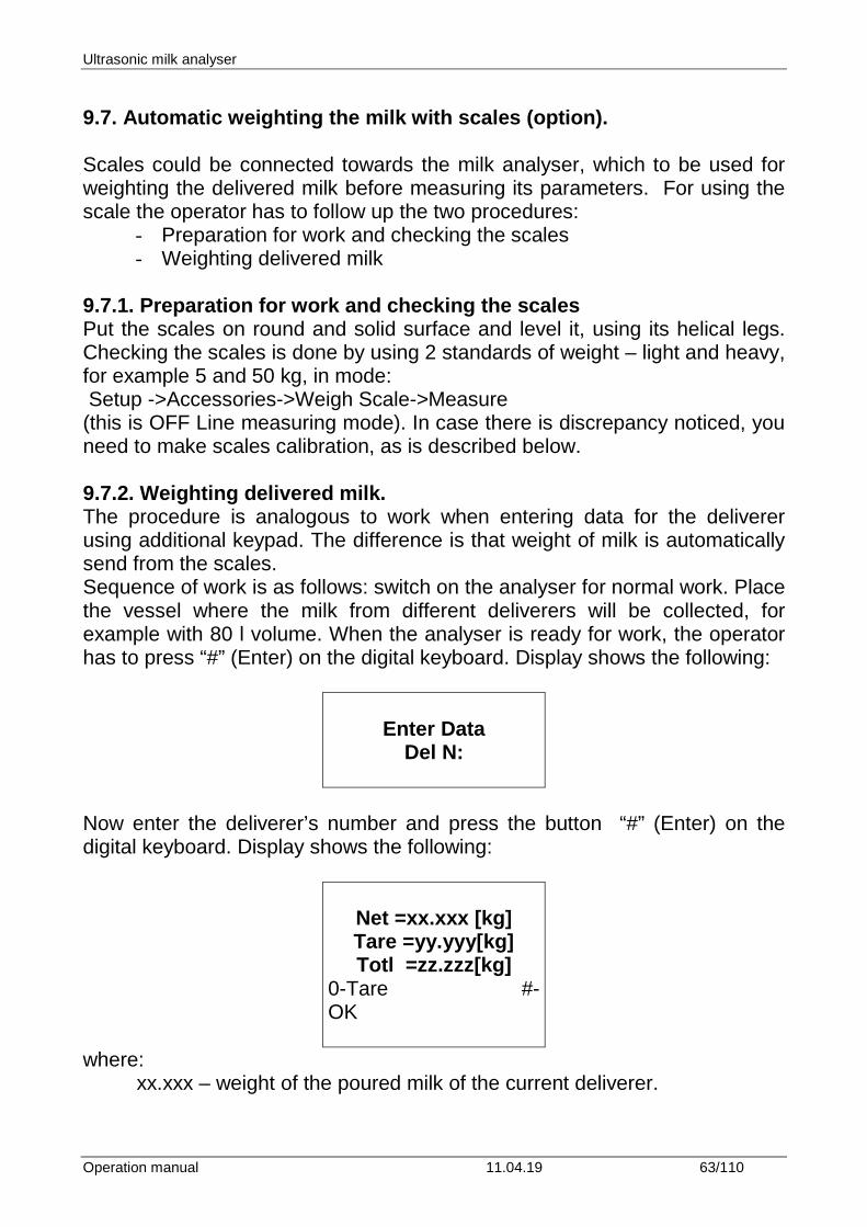
9.7.1. Preparation for work and checking the scales Put the scales on round and solid surface and level it, using its helical legs. Checking the scales is done by using 2 standards of weight – light and heavy, for example 5 and 50 kg, in mode: Setup ->Accessories->Weigh Scale->Measure (this is OFF Line measuring mode). In case there is discrepancy noticed, you need to make scales calibration, as is described below. 9.7.2. Weighting delivered milk. The procedure is analogous to work when entering data for the deliverer using additional keypad. The difference is that weight of milk is automatically send from the scales. Sequence of work is as follows: switch on the analyser for normal work. Place the vessel where the milk from different deliverers will be collected, for example with 80 l volume. When the analyser is ready for work, the operator has to press “#” (Enter) on the digital keyboard. Display shows the following:
Enter Data
Del N:
Now enter the deliverer’s number and press the button “#” (Enter) on the digital keyboard. Display shows the following:
Net =xx.xxx [kg] Tare =yy.yyy[kg] Totl =zz.zzz[kg]
0-Tare #-OK
where: xx.xxx – weight of the poured milk of the current deliverer.
Ultrasonic milk analyser
Operation manual 11.04.19 64/110
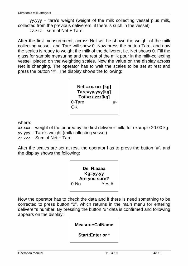
yy.yyy – tarе’s weight (weight of the milk collecting vessel plus milk, collected from the previous deliverers, if there is such in the vessel) zz.zzz – sum of Net + Tare After the first measurement, across Net will be shown the weight of the milk collecting vessel, and Tare will show 0. Now press the button Tare, and now the scales is ready to weight the milk of the deliverer, i.e. Net shows 0. Fill the glass for sample measuring and the rest of the milk pour in the milk-collecting vessel, placed on the weighting scales. Now the value on the display across Net is changing. The operator has to wait the scales to be set at rest and press the button “#”. The display shows the following:
Net =xx.xxx [kg] Tare=yy.yyy[kg] Totl=zz.zzz[kg]
0-Tare #-OK
where: xx.xxx – weight of the poured by the first deliverer milk, for example 20.00 kg. yy.yyy – Tare’s weight (milk collecting vessel) zz.zzz – Sum of Net + Tare After the scales are set at rest, the operator has to press the button “#”, and the display shows the following:
Del N:aaaa Kg=yy.yy
Are you sure? 0-No Yes-#
Now the operator has to check the data and if there is need something to be corrected to press button “0”, which returns in the main menu for entering deliverer’s number. By pressing the button “#” data is confirmed and following appears on the display:
Measure:CalName
Start:Enter or *
Ultrasonic milk analyser
Operation manual 11.04.19 65/110
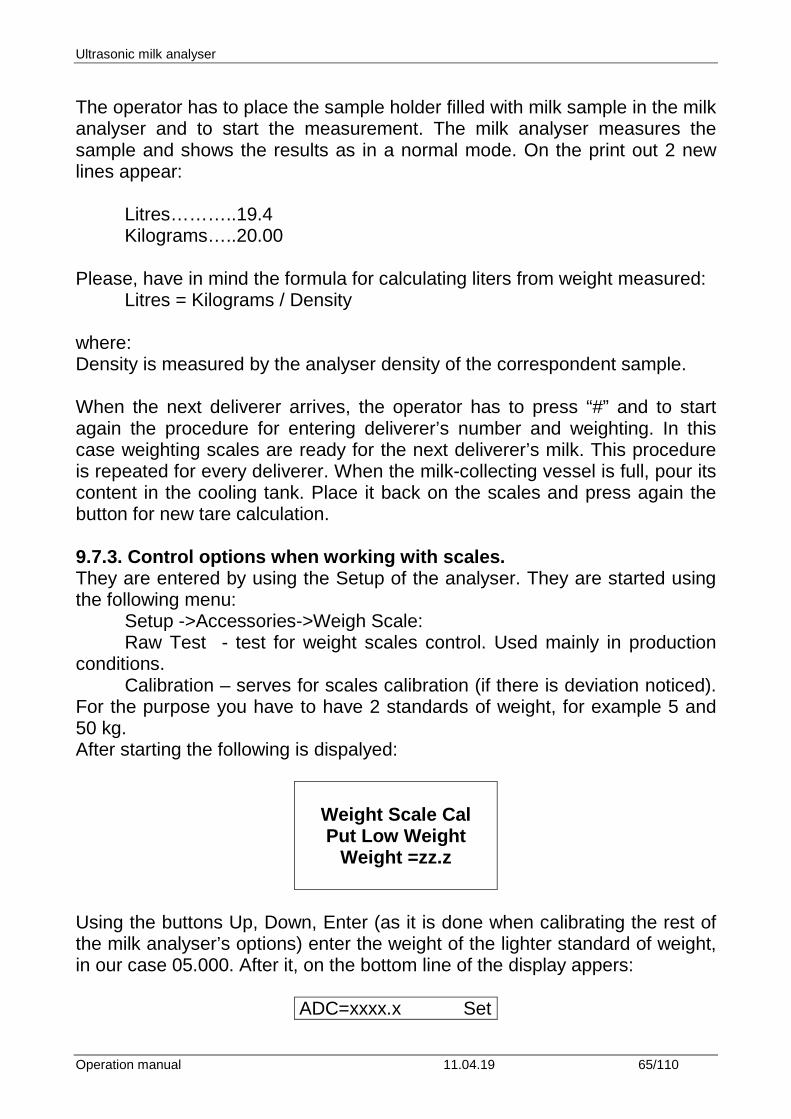
The operator has to place the sample holder filled with milk sample in the milk analyser and to start the measurement. The milk analyser measures the sample and shows the results as in a normal mode. On the print out 2 new lines appear: Litres………..19.4 Kilograms…..20.00 Please, have in mind the formula for calculating liters from weight measured: Litres = Kilograms / Density where: Density is measured by the analyser density of the correspondent sample. When the next deliverer arrives, the operator has to press “#” and to start again the procedure for entering deliverer’s number and weighting. In this case weighting scales are ready for the next deliverer’s milk. This procedure is repeated for every deliverer. When the milk-collecting vessel is full, pour its content in the cooling tank. Place it back on the scales and press again the button for new tare calculation. 9.7.3. Control options when working with scales. They are entered by using the Setup of the analyser. They are started using the following menu: Setup ->Accessories->Weigh Scale: Raw Test - test for weight scales control. Used mainly in production conditions. Calibration – serves for scales calibration (if there is deviation noticed). For the purpose you have to have 2 standards of weight, for example 5 and 50 kg. After starting the following is dispalyed:
Weight Scale Cal Put Low Weight
Weight =zz.z
Using the buttons Up, Down, Enter (as it is done when calibrating the rest of the milk analyser’s options) enter the weight of the lighter standard of weight, in our case 05.000. After it, on the bottom line of the display appers:
ADC=xxxx.x Set
Ultrasonic milk analyser
Operation manual 11.04.19 66/110
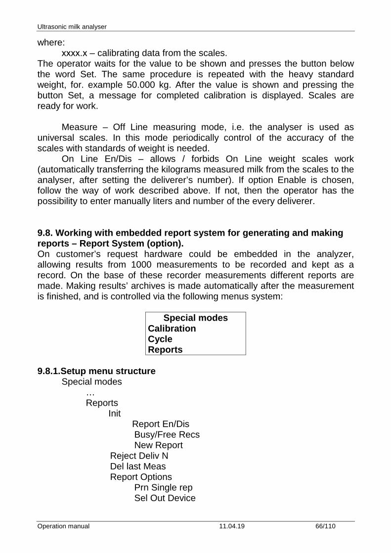
where: хххх.х – calibrating data from the scales. The operator waits for the value to be shown and presses the button below the word Set. The same procedure is repeated with the heavy standard weight, for. example 50.000 kg. After the value is shown and pressing the button Set, a message for completed calibration is displayed. Scales are ready for work. Measure – Off Line measuring mode, i.e. the analyser is used as universal scales. In this mode periodically control of the accuracy of the scales with standards of weight is needed. On Line En/Dis – allows / forbids On Line weight scales work (automatically transferring the kilograms measured milk from the scales to the analyser, after setting the deliverer’s number). If option Enable is chosen, follow the way of work described above. If not, then the operator has the possibility to enter manually liters and number of the every deliverer. 9.8. Working with embedded report system for generating and making reports – Report System (option). On customer’s request hardware could be embedded in the analyzer, allowing results from 1000 measurements to be recorded and kept as a record. On the base of these recorder measurements different reports are made. Making results’ archives is made automatically after the measurement is finished, and is controlled via the following menus system:
Special modes Calibration Cycle Reports
9.8.1.Setup menu structure Special modes … Reports
Init Report En/Dis
Busy/Free Recs New Report Reject Deliv N Del last Meas Report Options Prn Single rep Sel Out Device
Ultrasonic milk analyser
Operation manual 11.04.19 67/110
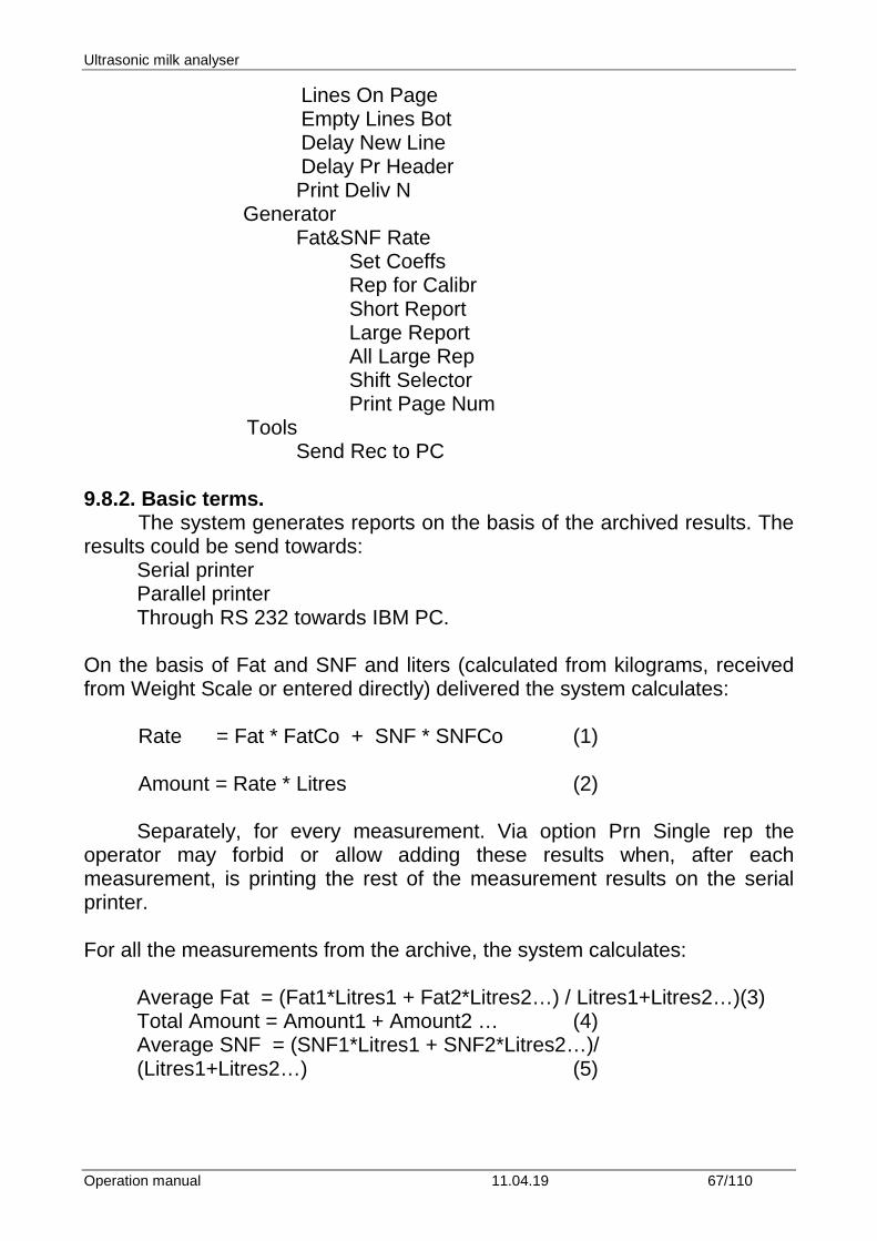
Lines On Page Empty Lines Bot Delay New Line Delay Pr Header
Print Deliv N Generator
Fat&SNF Rate Set Coeffs Rep for Calibr Short Report Large Report All Large Rep Shift Selector Print Page Num
Tools Send Rec to PC
9.8.2. Basic terms. The system generates reports on the basis of the archived results. The results could be send towards:
Serial printer Parallel printer Through RS 232 towards IBM PC.
On the basis of Fat and SNF and liters (calculated from kilograms, received from Weight Scale or entered directly) delivered the system calculates: Rate = Fat * FatCo + SNF * SNFCo (1) Amount = Rate * Litres (2)
Separately, for every measurement. Via option Prn Single rep the operator may forbid or allow adding these results when, after each measurement, is printing the rest of the measurement results on the serial printer. For all the measurements from the archive, the system calculates:
Average Fat = (Fat1*Litres1 + Fat2*Litres2…) / Litres1+Litres2…)(3) Total Amount = Amount1 + Amount2 … (4) Average SNF = (SNF1*Litres1 + SNF2*Litres2…)/ (Litres1+Litres2…) (5)
Ultrasonic milk analyser
Operation manual 11.04.19 68/110
Calculations are made for each separate calibration. Average results for Fat and SNF may be used for control of total gathered milk. In order to start working the report system needs the operator to enable it (Report En/Dis), and to set the old report in initial adjustment (New Report). Using IBM PC (via RS232 cable) user can enter the name of Milk collection center and names of 2 working shifts (i.e. Morning shift 1,2). During work the operator may delete the result from the archive for the last measurement (if there is a need to be done). Before starting generating the reports, coefficients, used for calculations have to be entered (Set Coeffs). After the working shift is over, the operator has the possibility to print out Short or Large Shift Report. User has possibilities to reject selected deliverer number from report (Reject Deliv N). 9.8.3. Menus’ description: Group Init:
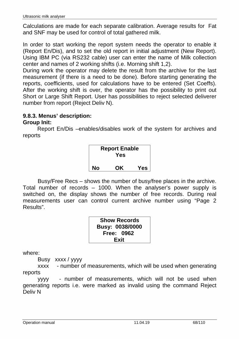
Report En/Dis –enables/disables work of the system for archives and reports
Report Enable Yes No OK Yes
Busy/Free Recs – shows the number of busy/free places in the archive. Total number of records – 1000. When the analyser’s power supply is switched on, the display shows the number of free records. During real measurements user can control current archive number using “Page 2 Results”.
Show Records Busy: 0038/0000 Free: 0962 Exit
where:
Busy xxxx / yyyy xxxx - number of measurements, which will be used when generating
reports yyyy - number of measurements, which will not be used when
generating reports i.e. were marked as invalid using the command Reject Deliv N
Ultrasonic milk analyser
Operation manual 11.04.19 69/110
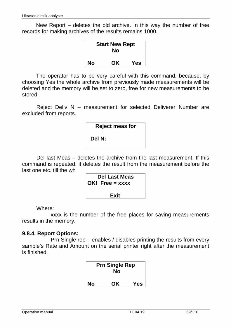
New Report – deletes the old archive. In this way the number of free records for making archives of the results remains 1000.
Start New Rept No
No OK Yes
The operator has to be very careful with this command, because, by
choosing Yes the whole archive from previously made measurements will be deleted and the memory will be set to zero, free for new measurements to be stored.
Reject Deliv N – measurement for selected Deliverer Number are excluded from reports.
Reject meas for Del N:
Del last Meas – deletes the archive from the last measurement. If this command is repeated, it deletes the result from the measurement before the last one etc. till the wh
Del Last Meas OK! Free = xxxx Exit
Where: хххх is the number of the free places for saving measurements results in the memory. 9.8.4. Report Options: Prn Single rep – enables / disables printing the results from every sample’s Rate and Amount on the serial printer right after the measurement is finished.
Prn Single Rep No No OK Yes
Ultrasonic milk analyser
Operation manual 11.04.19 70/110
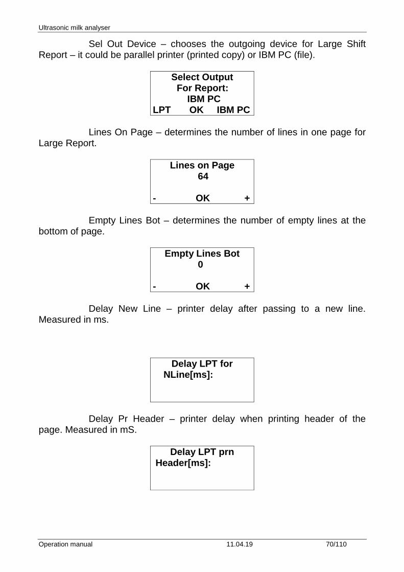
Sel Out Device – chooses the outgoing device for Large Shift Report – it could be parallel printer (printed copy) or IBM PC (file).
Select Output For Report: IBM PC LPT OK IBM PC
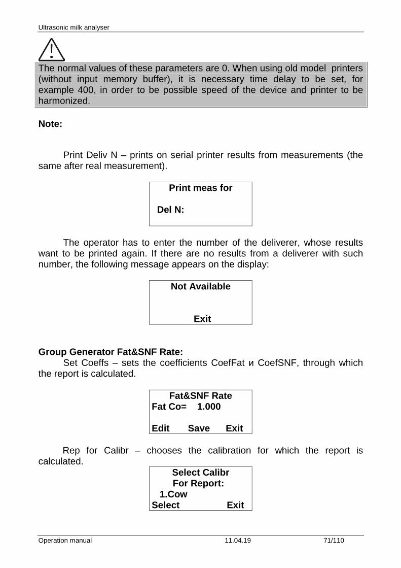
Lines On Page – determines the number of lines in one page for Large Report.
Lines on Page 64 - OK +
Empty Lines Bot – determines the number of empty lines at the bottom of page.
Empty Lines Bot 0 - OK +
Delay New Line – printer delay after passing to a new line.
Measured in ms.
Delay LPT for NLine[ms]:
Delay Pr Header – printer delay when printing header of the page. Measured in mS.
Delay LPT prn Header[ms]:
Ultrasonic milk analyser
Operation manual 11.04.19 71/110
The normal values of these parameters are 0. When using old model printers (without input memory buffer), it is necessary time delay to be set, for example 400, in order to be possible speed of the device and printer to be harmonized. Note: Print Deliv N – prints on serial printer results from measurements (the same after real measurement).
Print meas for Del N:
The operator has to enter the number of the deliverer, whose results want to be printed again. If there are no results from a deliverer with such number, the following message appears on the display:
Not Available Exit
Group Generator Fat&SNF Rate: Set Coeffs – sets the coefficients CoefFat и CoefSNF, through which the report is calculated.
Fat&SNF Rate Fat Co= 1.000 Edit Save Exit
Rep for Calibr – chooses the calibration for which the report is
calculated. Select Calibr
For Report: 1.Cow Select Exit
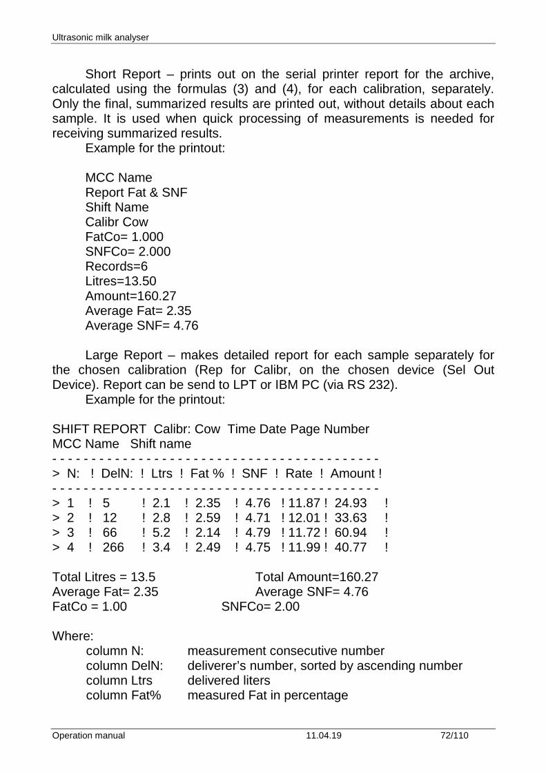
Ultrasonic milk analyser
Operation manual 11.04.19 72/110
Short Report – prints out on the serial printer report for the archive,
calculated using the formulas (3) and (4), for each calibration, separately. Only the final, summarized results are printed out, without details about each sample. It is used when quick processing of measurements is needed for receiving summarized results.
Example for the printout: MCC Name Report Fat & SNF Shift Name Calibr Cow FatCo= 1.000 SNFCo= 2.000 Records=6 Litres=13.50 Amount=160.27 Average Fat= 2.35 Average SNF= 4.76 Large Report – makes detailed report for each sample separately for
the chosen calibration (Rep for Calibr, on the chosen device (Sel Out Device). Report can be send to LPT or IBM PC (via RS 232).
Example for the printout:
SHIFT REPORT Calibr: Cow Time Date Page Number MCC Name Shift name - - - - - - - - - - - - - - - - - - - - - - - - - - - - - - - - - - - - - - - - - - > N: ! DelN: ! Ltrs ! Fat % ! SNF ! Rate ! Amount ! - - - - - - - - - - - - - - - - - - - - - - - - - - - - - - - - - - - - - - - - - - > 1 ! 5 ! 2.1 ! 2.35 ! 4.76 ! 11.87 ! 24.93 ! > 2 ! 12 ! 2.8 ! 2.59 ! 4.71 ! 12.01 ! 33.63 ! > 3 ! 66 ! 5.2 ! 2.14 ! 4.79 ! 11.72 ! 60.94 ! > 4 ! 266 ! 3.4 ! 2.49 ! 4.75 ! 11.99 ! 40.77 ! Total Litres = 13.5 Total Amount=160.27 Average Fat= 2.35 Average SNF= 4.76 FatCo = 1.00 SNFCo= 2.00 Where: column N: measurement consecutive number column DelN: deliverer’s number, sorted by ascending number column Ltrs delivered liters column Fat% measured Fat in percentage
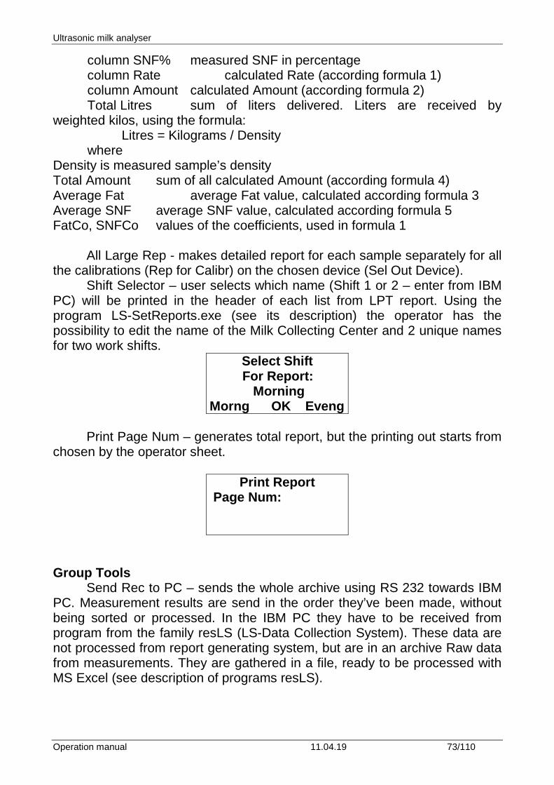
Ultrasonic milk analyser
Operation manual 11.04.19 73/110
column SNF% measured SNF in percentage column Rate calculated Rate (according formula 1) column Amount calculated Amount (according formula 2) Total Litres sum of liters delivered. Liters are received by weighted kilos, using the formula: Litres = Kilograms / Density where Density is measured sample’s density Total Amount sum of all calculated Amount (according formula 4) Average Fat average Fat value, calculated according formula 3 Average SNF average SNF value, calculated according formula 5 FatCo, SNFCo values of the coefficients, used in formula 1
All Large Rep - makes detailed report for each sample separately for all the calibrations (Rep for Calibr) on the chosen device (Sel Out Device).
Shift Selector – user selects which name (Shift 1 or 2 – enter from IBM PC) will be printed in the header of each list from LPT report. Using the program LS-SetReports.exe (see its description) the operator has the possibility to edit the name of the Milk Collecting Center and 2 unique names for two work shifts.
Select Shift For Report: Morning Morng OK Eveng
Print Page Num – generates total report, but the printing out starts from
chosen by the operator sheet.
Print Report Page Num:
Group Tools
Send Rec to PC – sends the whole archive using RS 232 towards IBM PC. Measurement results are send in the order they’ve been made, without being sorted or processed. In the IBM PC they have to be received from program from the family resLS (LS-Data Collection System). These data are not processed from report generating system, but are in an archive Raw data from measurements. They are gathered in a file, ready to be processed with MS Excel (see description of programs resLS).
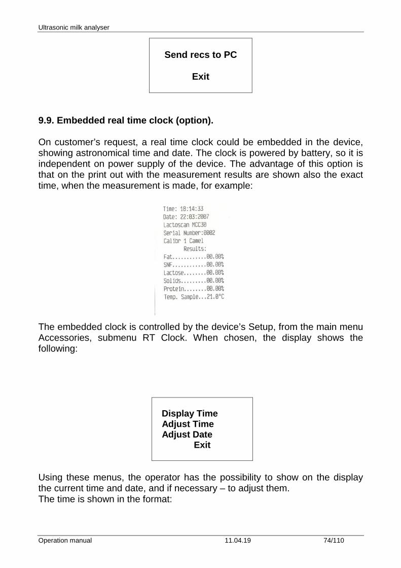
Ultrasonic milk analyser
Operation manual 11.04.19 74/110
Send recs to PC
Exit
9.9. Embedded real time clock (option). On customer’s request, a real time clock could be embedded in the device, showing astronomical time and date. The clock is powered by battery, so it is independent on power supply of the device. The advantage of this option is that on the print out with the measurement results are shown also the exact time, when the measurement is made, for example: The embedded clock is controlled by the device’s Setup, from the main menu Accessories, submenu RT Clock. When chosen, the display shows the following:
Display Time Adjust Time Adjust Date
Exit
Using these menus, the operator has the possibility to show on the display the current time and date, and if necessary – to adjust them. The time is shown in the format:
Ultrasonic milk analyser
Operation manual 11.04.19 75/110
hh:mm:ss dd:mm:yy Exit
where: hh - the current hour mm - current minutes
ss - current seconds dd - current day mm - current month yy - current year 9.10. USB Flash-drive (pen drive) (option). This option allows connecting standard USB Flash Drive (Pen Drive) towards the Lactoscan. Its usage allows automatically (without operator’s interfere) creating total archive of all measurements, made with the analyzer. Actions necessary for switching on/off the USB Flash Drive are analogous to the same when working with PC. After USB Flash Drive is inserted in the coupling at the front panel of the analyzer, Lactoscan starts writing there the results from each measurement. If you do not need to make an archive, then simply remove the flash drive from the analyser. As when working in PC, when the flash reads/writes its LED blinks. I this case wait for the Led stop blinking and then remove the flash drive from the analyser. Data, collected from measurements, are saved in MS Excel file. The name of the file is formed by the date, when the measurement is made (in case there’s embedded clock option). For example – 111213.xls means, that the file was created in year 2011(last two digits from the year), month 12 – December, day13. Tabs with results are in accordance with software resLS, i.e. the file, created on the flash drive is with the same structure and may be processed with the same, already existent client software, used for collecting data with PC (see the manual of the software resLS.exe). Meaning of results tabs are in the file LS-USB.XLS. The difference is, that if there’s flash drive connected to Lactoscan during measurements, there’s no need the analyzer to be connected to PC all the time. In the presence of more than 1 analyzer, each of them may be equipped with flash drive and at the end of the shift (working day or after a definite period of time (chosen by the customer) files from different analyzers to be processed on only one PC.
Ultrasonic milk analyser
Operation manual 11.04.19 76/110
It is recommended this option to be used in combination with RTC and Keypad. Availability of clock option ensures archive of the time when the measurement was taken. Clock adjustment can be made with the software tool LS-AdjustRTClock.exe (see its manual). In presence of Keypad, the deliverer’s number can be entered (or some kind of number/identifier of the sample) – number from 1 to 9999 and liters/kg of the milk. There’s no requirement for type and producer of the Flash Drive, as well as its storage capacity. Other files, working under MS Windows may be also present on the flash drive. Approximately, results from one measurement, take less than 100 bytes. For example, flash drive of 8 GB, can store more than 80 000 000 measurements, which makes it unlimited from point of view archive of measurement results.
Use this option ONLY with flash-drives. Do not connect any other USB devices. The idea of embedding standard USB Flash-Drive (Pen Drive) in the analyser is to move to a qualitatively new level in terms of storage and processing of the measurement results. The Flash-Drive is used as memory for storing the results. Having in mind the memory volume, necessary for storing the results from one measurement, Flash-Drives – available on the market are in fact unlimited memory, i.e if the analyser is working normally it could not be filled in totally. Flash-Drive Controller development keep all the standard convenient features for work with it – there’s no limitation when to be connected to the analyser – it may happen any time. As it is when Flash-Drive is placed in PC, on the same way, the Flash-Drive may be removed from the analyser in case it is not working (its LED is not blinking). It works with the file structure of MS Windows, the file names are unique, based on the current date. In this case on the same Flash-Drive can be stored whatever other files the customer needs to store on it. Files, generated by the analyser are type MS Excel, ready to be processed with a computer. What kind of advantages using Flash-Drive gives? overcomes the restriction of using limited internal memory of the analyser for collecting data; There’s no need of constant connection between LS and PC or LS – specialized external device for collecting data. The only thing needed is to
Ultrasonic milk analyser
Operation manual 11.04.19 77/110
place the Flash-Drive in the USB coupling when needed and remove it when it is not needed – that’s the total training an operator needs. Having in mind above described mobility of this option, there are different scenarios for using it, depending on the specific conditions. Example for mobile version: Lactoscan milk analyser is used on a milk collecting truck, which is going from place to place to collect milk. Lactoscan is powered by the accumulator of the truck (through the car-lighter for example). The operator of the analyser enters (with the embedded in the upper cover of Lactoscan milk analyser keypad) the deliverer’s number and liters delivered, takes sample and starts measurement of its parameters. After the measurement is finished, the measured results, together with the already entered by the operator data for the milk deliverer automatically, without operators interfere are stored on the Flash-Drive. On practice, this operation is “invisible” for the operator, does not take additional time and the operator has the possibility to start servicing the next deliverer. After arriving in the base (milk collecting center/dairy), the operator has just to disconnect the Flash-Drive and give it to the laboratory, which, in fact, is his daily report for the work he has done. Results are transferred to a PC as standard files and as per the strategy accepted – they can be saved or removed/deleted from the flash. And all this can happen within 1-2 minutes, which makes the total process of reporting and archiving the results automatic. Even to make the process faster, it is possible to make weighting the milk automatic – in dependence of end-user choice, according the available technique, weight scales may be connected to the analyser – via analog or serial channel. In this case, after entering suppliers’ number, the analyser passes automatically in mode weighting scales and starts accepting data coming from the connected to it weight scales. The way of saving the results on the Flash-Drive is exactly the same as described when data are entered via the keypad.
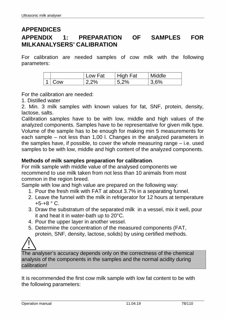
Ultrasonic milk analyser
Operation manual 11.04.19 78/110
APPENDICES APPENDIX 1: PREPARATION OF SAMPLES FOR MILKANALYSERS’ CALIBRATION For calibration are needed samples of cow milk with the following parameters:
Low Fat High Fat Middle 1 Cow 2,2% 5,2% 3,6%
For the calibration are needed: 1. Distilled water 2. Min. 3 milk samples with known values for fat, SNF, protein, density, lactose, salts. Calibration samples have to be with low, middle and high values of the analyzed components. Samples have to be representative for given milk type. Volume of the sample has to be enough for making min 5 measurements for each sample – not less than 1,00 l. Changes in the analyzed parameters in the samples have, if possible, to cover the whole measuring range – i.e. used samples to be with low, middle and high content of the analyzed components. Methods of milk samples preparation for calibration. For milk sample with middle value of the analysed components we recommend to use milk taken from not less than 10 animals from most common in the region breed. Sample with low and high value are prepared on the following way:
1. Pour the fresh milk with FAT at about 3.7% in a separating funnel. 2. Leave the funnel with the milk in refrigerator for 12 hours at temperature
+5-+8 ° C. 3. Draw the substratum of the separated milk in a vessel, mix it well, pour
it and heat it in water-bath up to 20°C. 4. Pour the upper layer in another vessel. 5. Determine the concentration of the measured components (FAT,
protein, SNF, density, lactose, solids) by using certified methods.
The analyser’s accuracy depends only on the correctness of the chemical analysis of the components in the samples and the normal acidity during calibration! It is recommended the first cow milk sample with low fat content to be with the following parameters:
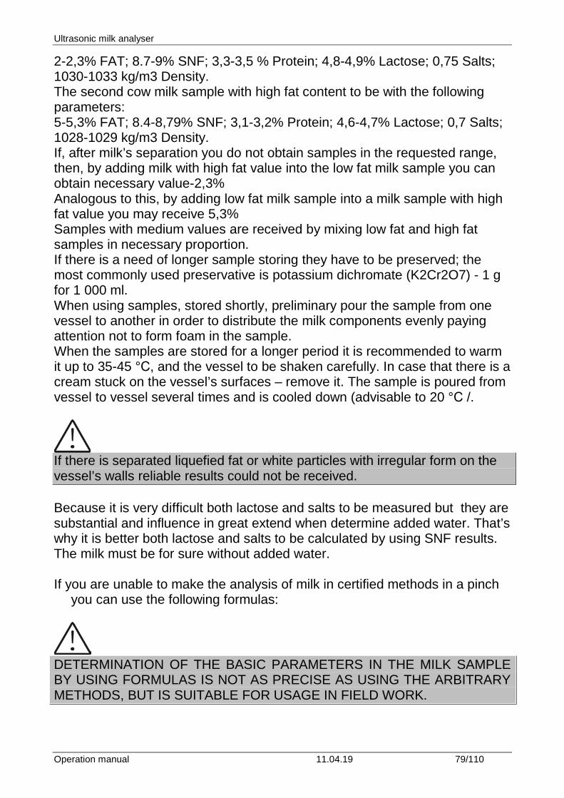
Ultrasonic milk analyser
Operation manual 11.04.19 79/110
2-2,3% FAT; 8.7-9% SNF; 3,3-3,5 % Protein; 4,8-4,9% Lactose; 0,75 Salts; 1030-1033 kg/m3 Density. The second cow milk sample with high fat content to be with the following parameters: 5-5,3% FAT; 8.4-8,79% SNF; 3,1-3,2% Protein; 4,6-4,7% Lactose; 0,7 Salts; 1028-1029 kg/m3 Density. If, after milk’s separation you do not obtain samples in the requested range, then, by adding milk with high fat value into the low fat milk sample you can obtain necessary value-2,3% Analogous to this, by adding low fat milk sample into a milk sample with high fat value you may receive 5,3% Samples with medium values are received by mixing low fat and high fat samples in necessary proportion. If there is a need of longer sample storing they have to be preserved; the most commonly used preservative is potassium dichromate (K2Cr2O7) - 1 g for 1 000 ml. When using samples, stored shortly, preliminary pour the sample from one vessel to another in order to distribute the milk components evenly paying attention not to form foam in the sample. When the samples are stored for a longer period it is recommended to warm it up to 35-45 °С, and the vessel to be shaken carefully. In case that there is a cream stuck on the vessel’s surfaces – remove it. The sample is poured from vessel to vessel several times and is cooled down (advisable to 20 °С /.
If there is separated liquefied fat or white particles with irregular form on the vessel’s walls reliable results could not be received. Because it is very difficult both lactose and salts to be measured but they are substantial and influence in great extend when determine added water. That’s why it is better both lactose and salts to be calculated by using SNF results. The milk must be for sure without added water. If you are unable to make the analysis of milk in certified methods in a pinch
you can use the following formulas:
DETERMINATION OF THE BASIC PARAMETERS IN THE MILK SAMPLE BY USING FORMULAS IS NOT AS PRECISE AS USING THE ARBITRARY METHODS, BUT IS SUITABLE FOR USAGE IN FIELD WORK.
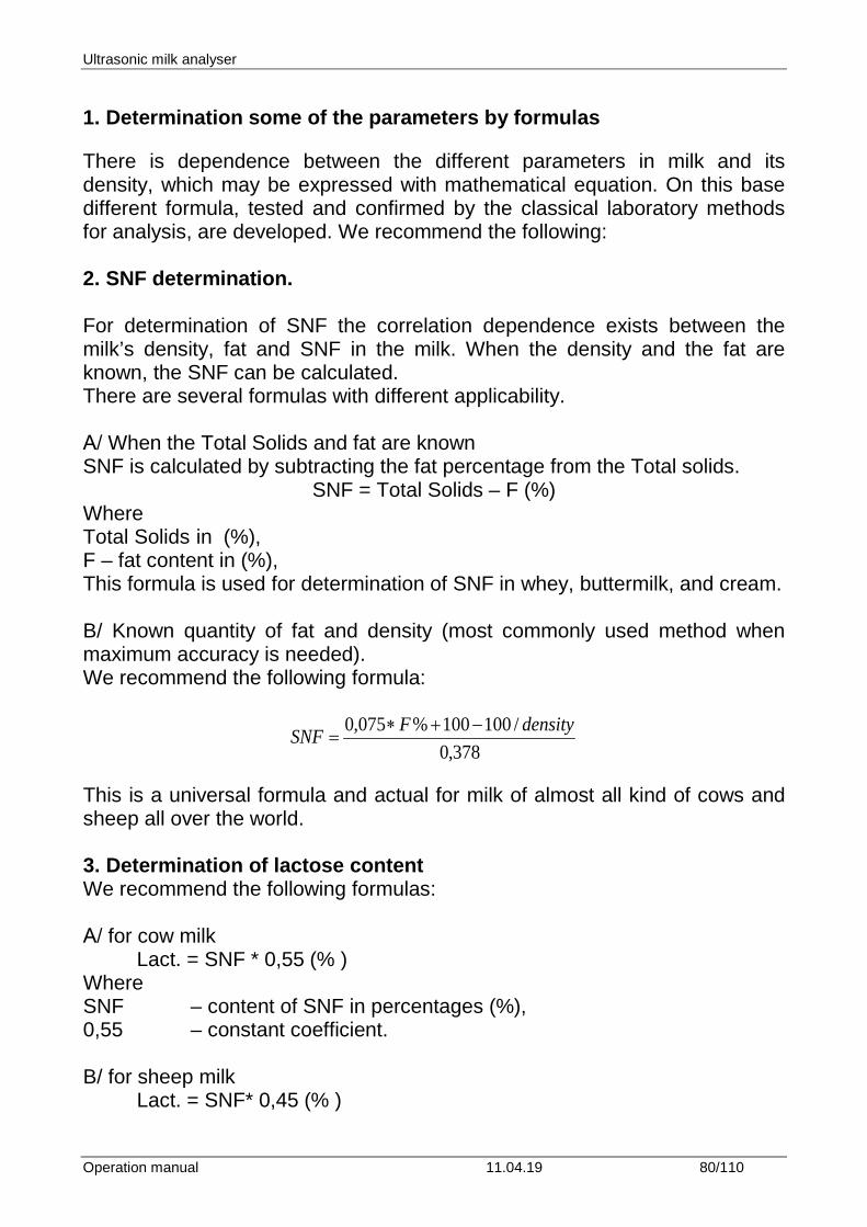
Ultrasonic milk analyser
Operation manual 11.04.19 80/110
1. Determination some of the parameters by formulas
There is dependence between the different parameters in milk and its density, which may be expressed with mathematical equation. On this base different formula, tested and confirmed by the classical laboratory methods for analysis, are developed. We recommend the following: 2. SNF determination. For determination of SNF the correlation dependence exists between the milk’s density, fat and SNF in the milk. When the density and the fat are known, the SNF can be calculated. There are several formulas with different applicability. А/ When the Total Solids and fat are known SNF is calculated by subtracting the fat percentage from the Total solids.
SNF = Total Solids – F (%) Where Total Solids in (%), F – fat content in (%), This formula is used for determination of SNF in whey, buttermilk, and cream. B/ Known quantity of fat and density (most commonly used method when maximum accuracy is needed). We recommend the following formula: This is a universal formula and actual for milk of almost all kind of cows and sheep all over the world. 3. Determination of lactose content We recommend the following formulas: А/ for cow milk Lact. = SNF * 0,55 (% ) Where SNF – content of SNF in percentages (%), 0,55 – constant coefficient. B/ for sheep milk
Lact. = SNF* 0,45 (% )
378,0/100100%075,0 densityFSNF −+∗
=
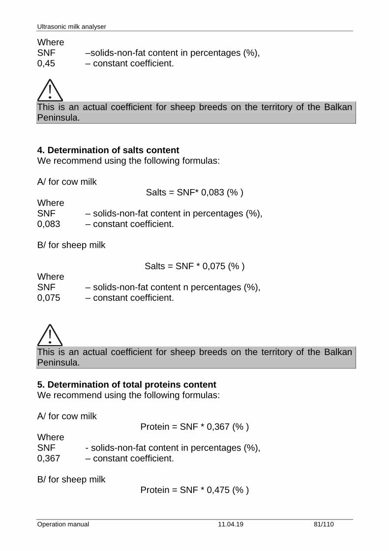
Ultrasonic milk analyser
Operation manual 11.04.19 81/110
Where SNF –solids-non-fat content in percentages (%), 0,45 – constant coefficient.
This is an actual coefficient for sheep breeds on the territory of the Balkan Peninsula. 4. Determination of salts content We recommend using the following formulas: А/ for cow milk
Salts = SNF* 0,083 (% ) Where SNF – solids-non-fat content in percentages (%), 0,083 – constant coefficient. B/ for sheep milk
Salts = SNF * 0,075 (% ) Where SNF – solids-non-fat content n percentages (%), 0,075 – constant coefficient.
This is an actual coefficient for sheep breeds on the territory of the Balkan Peninsula. 5. Determination of total proteins content We recommend using the following formulas: А/ for cow milk
Protein = SNF * 0,367 (% ) Where SNF - solids-non-fat content in percentages (%), 0,367 – constant coefficient. B/ for sheep milk
Protein = SNF * 0,475 (% )
Ultrasonic milk analyser
Operation manual 11.04.19 82/110
Where SNF – solids-non-fat content in percentages (%), 0,475 - constant coefficient.
This is an actual coefficient for sheep breeds on the territory of the Balkan Peninsula.
Ultrasonic milk analyser
Operation manual 11.04.19 83/110
APPENDIX 2 FREEZING POINT DETERMINATION 1. Methods for determination. The milk analyzer determines the freezing point of each sample and the quantity of added water. The milk analyser does not measure the freezing point, but calculates it from the components it depends on. The basic components in the milk are water, salts, lactose, FAT, proteins, minerals (salts) and acids. The freezing point depends only on the diluted in the milk components and quantity of the solvent (in the milk it is water). The ultrasonic technology allows direct measurement of FAT, proteins, lactose + salts (the soluble components, only influencing the freezing point), and the quantity of the solvent in % is determined by 100 % – total solids %, total solids = lactose % + FAT % + proteins % + salts % + acids %. Without understanding the meaning of the freezing point – determined or shown from the milk analyzer added water result easily may lead to a mistake for the value of this parameter. 2. The basic freezing point. Milk freezes at lower temperature than water. The average freezing point of the raw milk in the most regions is at about -0,540°С. The average reading for your region is called “basic” freezing point. The freezing point of milk is a “physiological constant”. This does not mean that it will not vary. In fact feed, breed, season, time of lactation, climate, whether the sample is taken at the beginning, middle or end of lactation – all these factors will have an effect on the freezing point of the individual sample. This means that there is an average value of all these numbers. The more samples used in obtaining this average, the more reliable it is as a base. Or the basic freezing point is an average of freezing points of milk, taken from many cows. When a laboratory checks a producer, it is only comparing the average of the producer’s cows against a larger area average. The Health authorities establish the basic freezing point or agriculture departments in some regions, sometimes by universities, separate dairy producers, or their associations. Frequently, tolerances have been established on top of a basic freezing point to allow some variations in the milk as well as device or operator variations. Without mentioning the basic freezing point, the Association of Official Analytical Chemists now recommends an upper limit freezing point at -0,525°C (2,326 standard deviations above the most recently determined North American average of –0,5404°C), below which there will be at 95%
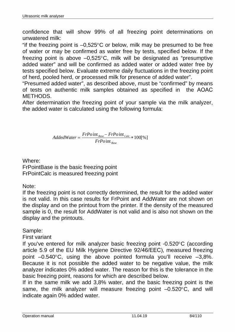
Ultrasonic milk analyser
Operation manual 11.04.19 84/110
confidence that will show 99% of all freezing point determinations on unwatered milk: “if the freezing point is –0,525°C or below, milk may be presumed to be free of water or may be confirmed as water free by tests, specified below. If the freezing point is above –0,525°C, milk will be designated as “presumptive added water” and will be confirmed as added water or added water free by tests specified below. Evaluate extreme daily fluctuations in the freezing point of herd, pooled herd, or processed milk for presence of added water”. “Presumed added water”, as described above, must be “confirmed” by means of tests on authentic milk samples obtained as specified in the АОАС METHODS. After determination the freezing point of your sample via the milk analyzer, the added water is calculated using the following formula: [%]100
intintint
∗−
=Base
CalcBase
FrPoFrPoFrPo
AddedWater
Where: FrPointBase is the basic freezing point FrPointCalc is measured freezing point Note: If the freezing point is not correctly determined, the result for the added water is not valid. In this case results for FrPoint and AddWater are not shown on the display and on the printout from the printer. If the density of the measured sample is 0, the result for AddWater is not valid and is also not shown on the display and the printouts. Sample: First variant If you’ve entered for milk analyzer basic freezing point -0.520°C (according article 5.9 of the EU Milk Hygiene Directive 92/46/ЕЕС), measured freezing point –0.540°C, using the above pointed formula you’ll receive –3,8%. Because it is not possible the added water to be negative value, the milk analyzer indicates 0% added water. The reason for this is the tolerance in the basic freezing point, reasons for which are described below. If in the same milk we add 3,8% water, and the basic freezing point is the same, the milk analyzer will measure freezing point –0.520°C, and will indicate again 0% added water.
Ultrasonic milk analyser
Operation manual 11.04.19 85/110
Second variant If you’ve entered for the device basic freezing point –0.540°C, measured freezing point –0.540°C, the milk analyzer will indicate 0%. When you add 3,8% water, the device will indicate 3,8%-added water. From the above mentioned follows that it is very important to enter correct basic freezing point in the device. The device’s results for added water may give information about doubt of added water in the milk and the exact value of this added water may be determined after a “cowshed sample” is taken and the result for the freezing point, measured by the milk analyzer of the “cowshed sample” is entered as basic freezing point in the formula for calculation of added water. Then the result from this formula will give us the absolute value of the added water for the corresponding milk supplier.
Ultrasonic milk analyser
Operation manual 11.04.19 86/110
APPENDIX 3 PH MEASURING 1. General information PH probe is a unit, measuring the solution acidity or alkalinity degree. It is measured on scale of 0 to 14. The term pH is derived from "p", the mathematical symbol for the negative logarithm, and "H", the chemical symbol of Hydrogen. The formal definition of pH is the negative logarithm of the Hydrogen ion activity. 2. pH Electrode For pH measurement the milk analyzer needs a combination electrode, compatible with most pH electrodes that have BNC connectors and zero potential (the pH where the mill volt output of the electrode equals 0) near 7 pH.
2.1. Electrode part The electrode is the most important part of the pH measurement. The electrode glass membrane is fragile and must be handled with care. To protect the glass membrane and to maintain activation, a protective rubber cap containing a suitable storage solution covers the glass membrane.
2.2. Electrode care & Electrode maintenance pH Electrodes are susceptible to dirt and contamination and need to be clean regularly depending on the extent and condition of use. At no time should one touch or rub the glass bulb as this causes the build-up of electrostatic charge.
2.3. Storage For best results, always keep the pH bulb wet. An optimal storage solution for combination electrode is pH 4 buffer with 225 grams of KCl per liter. Table salt, NaCl, can be used if KCl is not really available. Other pH buffers or tap water are also acceptable storage media, but avoid storage in de-ionized water. The protective rubber cap filled with the buffer solution provides ideal storage for long periods.
2.4. After Use After measurement is completed, follow the sequence below for storage. - Wash the electrode and reference junction in de-ionized water. - Close the refilling hole by returning its rubber sleeve or stopper cap. (Necessary for only refillable electrode). - Store the electrode as mentioned above (see section Storage).
Ultrasonic milk analyser
Operation manual 11.04.19 87/110
2.5. Electrolyte Replacement (for refillable electrode only).
The reference electrolyte needs to be refilled when the electrode has been used for a long period, or when the internal electrolyte has dried up. To accomplish this, follow the procedure described below.
- Remove the protective rubber cap or sleeve; - Remove the protective rubber sleeve to expose the filling port of the
electrode; - Remove the old reference electrolyte with a syringe; - Fill the new reference electrolyte.
2.6. New electrolyte preparation:
- Open the KCl container; - Add in de-ionized water until it reaches the level of 20 ml; - Close the container and shake it to dissolve the KCl; - Add in fresh electrolyte until it reaches the level of the refilling port. The
reference electrolyte used should be 3M(Mol) KCl; - Replace the rubber sleeve.
2.7. Re-use the electrode.
- Rinse the liquid junction with de-ionized water.
If these steps fail to restore normal electrode response, you may attempt to rejuvenate it (See: Electrode Rejuvenation).
2.8. Electrode cleaning Electrodes which are mechanically intact can often be restored to normal performance by one or combination of the following procedures. - Salt deposits: Dissolve the deposit by immersing the electrode in tap water for ten to fifteen minutes. Then thoroughly rinse with de-ionized water. Wash the electrode pH bulb in a little detergent and water. Rinse electrode tip in with de-ionized water. - Oil/Grease films: Wash electrode pH bulb in a little detergent and water. Rinse electrode tip with de-ionized water. - Clogged Reference Junction: pH electrodes have junction, which allows the internal fill solution of the measuring electrode to leak out into the solution being measured. The
Ultrasonic milk analyser
Operation manual 11.04.19 88/110
junction can become clogged by contamination in the solution. If a clogged junction is suspected it is best to clear the junction. Heat up the diluted KCl solution to 60-80°C. Place the sensing part of the pH electrode into the heated KCl solution for approximately 10 minutes. Allow the electrode to cool while immersed in some unheated KCl solution. - Protein Deposits Prepare 1% pepsin solution in 0.1 M HCI. Allow the electrode to stand in this solution for five to ten minutes. Rinse the electrode with de-ionized water.
2.9. Electrode activation Generally, if the procedure of storage and maintenance had been closely followed, the electrode can be used immediately. However, should the electrode response become sluggish, it may be possible that the bulb has dehydrated. The bulb can be dehydrated by immersing the electrode in an ideal storage solution (e.g. buffer pH 4 solution) for 1-2 hours. If this fails, the electrode may require re-activation. If the above procedure does not reactivate the electrode to acceptable status, try rejuvenation the electrode by following the procedure outlined below.
2.10. Rejuvenation Procedure Dip and stir the electrode in freon or alcohol for 5 minutes. Leave the electrode in tap water for 15 minutes. Dip and stir the electrode in concentrated acid (HCI, H2S4) for 5 minutes. Leave the electrode in tap water for 15 minutes. Dip and stir in strong base (NaOH) for 5 minutes. Leave the electrode in tap water for 15 minutes. Test with standard calibration solution. Finally, test with standard calibration buffer solution to see if the electrode yields acceptable results. You may repeat again for better response (maximum 3 times). If the response does not improve, then the electrode has completed its useful life. Replace with a new electrode.
2.11. Electrode Lifespan pH electrodes have a finite lifespan due to their inherent properties. How long a pH electrode will last will depend on how it is cared and the solution it is used to measure. Even if an electrode is not used it still ages. Electrode demise can usually be characterized by a sluggish response, erratic readings or a reading, which will not change. When this occurs an electrode can no longer be calibrated. pH electrodes are fragile and have a limited lifespan. How long an electrode will last is determined by how well is maintained and the pH application. The harsher the system, the shorter the lifespan. For this
Ultrasonic milk analyser
Operation manual 11.04.19 89/110
reason it is always a good idea to have a back-up electrode on hand to avoid any system down time. 3. Buffer Solutions Buffers are solutions that have constant pH values and the ability to resist changes in that pH level. They are used to calibrate pH measurement system.
PH buffer solution description ( Pharmacopoeia standard)
Use only this types standard buffers for calibration! Description pH 7.00±0,01/20ºC pH 4.00±0,01/20ºC Composition Potassium dihydrogen
phosphate, Di-sodium hydrogen phosphate
Borax, Sodium hydroxide solution
Temperature parameters
10ºC - 7.06 25ºC - 6.99 20ºC - 7.00 30ºC - 6.98 40ºC - 6.95 50ºC - 6.91
10ºC - 4.00 25ºC - 4.00 20ºC - 4.00 30ºC - 4.00 40ºC - 4.00 50ºC - 4.05
4. pH Electrode Calibration pH Electrodes are like batteries; they run down with time and use. As an electrode ages, its glass changes resistance. For this reason, electrodes need to be calibrated on a regular basis. Calibration in pH buffer solution corrects for this change. Calibration is an important part of electrode maintenance. This assures not only that the electrode is behaving properly but that the system is operating correctly. Usually pH meters require calibration at 3 specific pH values. One calibration is usually performed at pH 7, second and third are typically performed at pH 4 and pH 10.
It is best to select a buffer as close as possible to the actual pH value of the sample to be measured. Use standard calibration buffers that the temperature and the sample solution are the same. Use the operation manual for the corresponding pH meter.
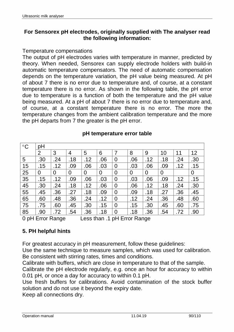
Ultrasonic milk analyser
Operation manual 11.04.19 90/110
For Sensorex pH electrodes, originally supplied with The analyser read
the following information: Temperature compensations The output of pH electrodes varies with temperature in manner, predicted by theory. When needed, Sensorex can supply electrode holders with build-in automatic temperature compensators. The need of automatic compensation depends on the temperature variation, the pH value being measured. At pH of about 7 there is no error due to temperature and, of course, at a constant temperature there is no error. As shown in the following table, the pH error due to temperature is a function of both the temperature and the pH value being measured. At a pH of about 7 there is no error due to temperature and, of course, at a constant temperature there is no error. The more the temperature changes from the ambient calibration temperature and the more the pH departs from 7 the greater is the pH error.
pH temperature error table
°C pH 2 3 4 5 6 7 8 9 10 11 12
5 .30 .24 .18 .12 .06 0 .06 .12 .18 .24 .30 15 .15 .12 .09 .06 .03 0 .03 .06 .09 .12 .15 25 0 0 0 0 0 0 0 0 0 0 35 .15 .12 .09 .06 .03 0 .03 .06 .09 .12 .15 45 .30 .24 .18 .12 .06 0 .06 .12 .18 .24 .30 55 .45 .36 .27 .18 .09 0 .09 .18 .27 .36 .45 65 .60 .48 .36 .24 .12 0 .12 .24 .36 .48 .60 75 .75 .60 .45 .30 .15 0 .15 .30 .45 .60 .75 85 .90 .72 .54 .36 .18 0 .18 .36 .54 .72 .90 0 pH Error Range Less than .1 pH Error Range 5. PH helpful hints For greatest accuracy in pH measurement, follow these guidelines: Use the same technique to measure samples, which was used for calibration. Be consistent with stirring rates, times and conditions. Calibrate with buffers, which are close in temperature to that of the sample. Calibrate the pH electrode regularly, e.g. once an hour for accuracy to within 0.01 pH, or once a day for accuracy to within 0.1 pH. Use fresh buffers for calibrations. Avoid contamination of the stock buffer solution and do not use it beyond the expiry date. Keep all connections dry.
Ultrasonic milk analyser
Operation manual 11.04.19 91/110
Immerse the electrode far enough into the solution to insure the reference junction is below the surface. Allow adequate time for the electrode to stabilize in standards and samples before taking a reading. Clean the electrode periodically. Allow more time for aged electrodes. Do not use the pH electrode in solutions of fluoride ion at low pH. This will etch the glass membrane. Sulphide vapors can permeate the electrode wick and contaminate the reference element. Minimize contact in such environments and change the reference electrolyte frequently.
6.Preparation for pH measurement When the analyzer is with pH measuring option, it is received from the customer with pH probe packed separately and there’s a stopper on its place. If you need to measure pH follow the procedure below: 1. Loose the nut anti-clockwise. 2. pull up the stopper
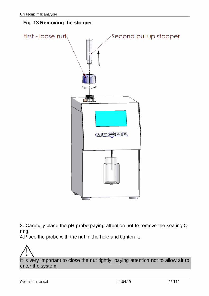
Ultrasonic milk analyser
Operation manual 11.04.19 92/110
Fig. 13 Removing the stopper
3. Carefully place the pH probe paying attention not to remove the sealing O-ring. 4.Place the probe with the nut in the hole and tighten it.
It is very important to close the nut tightly, paying attention not to allow air to enter the system.
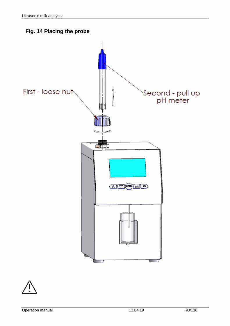
Ultrasonic milk analyser
Operation manual 11.04.19 93/110
Fig. 14 Placing the probe
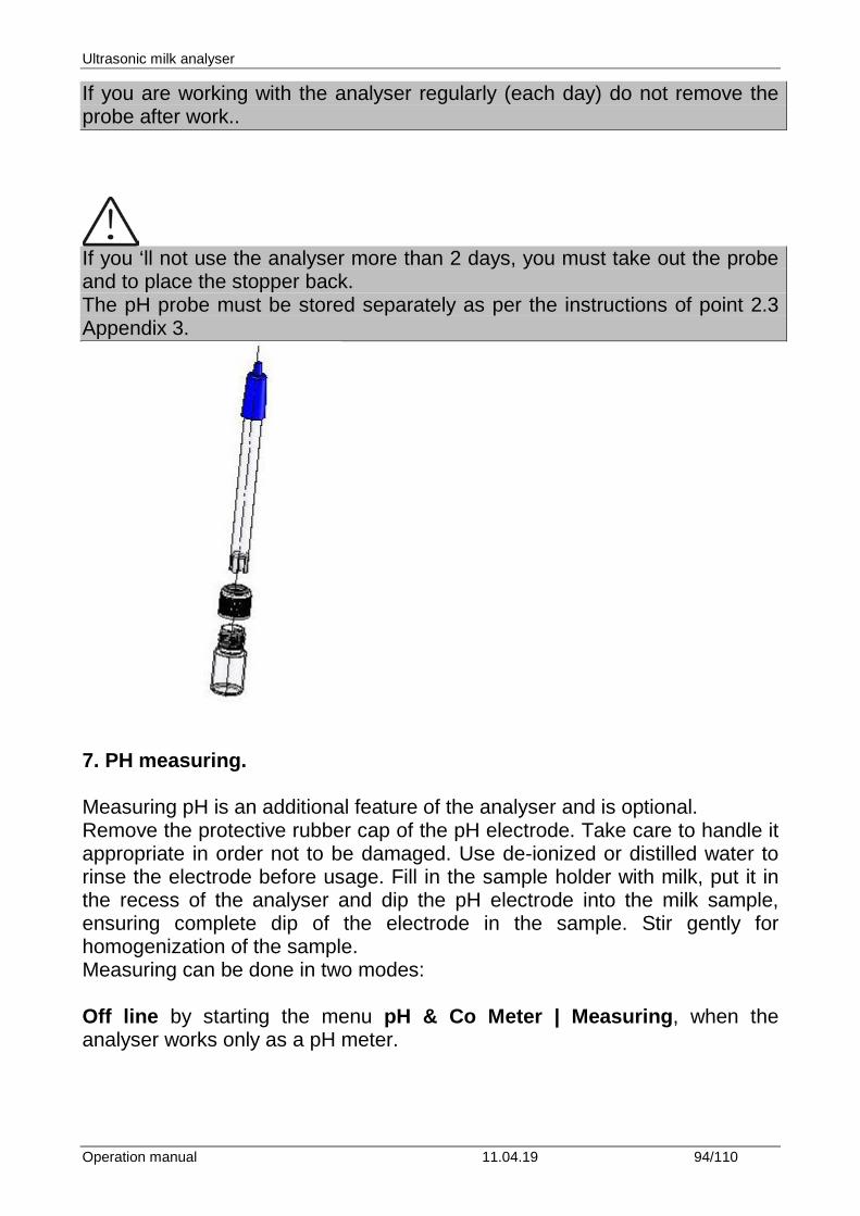
Ultrasonic milk analyser
Operation manual 11.04.19 94/110
If you are working with the analyser regularly (each day) do not remove the probe after work..
If you ‘ll not use the analyser more than 2 days, you must take out the probe and to place the stopper back. The pH probe must be stored separately as per the instructions of point 2.3 Appendix 3.
7. PH measuring. Measuring pH is an additional feature of the analyser and is optional. Remove the protective rubber cap of the pH electrode. Take care to handle it appropriate in order not to be damaged. Use de-ionized or distilled water to rinse the electrode before usage. Fill in the sample holder with milk, put it in the recess of the analyser and dip the pH electrode into the milk sample, ensuring complete dip of the electrode in the sample. Stir gently for homogenization of the sample. Measuring can be done in two modes: Off line by starting the menu pH & Co Meter | Measuring, when the analyser works only as a pH meter.
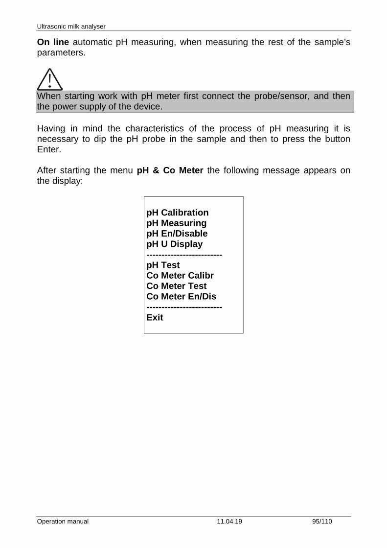
Ultrasonic milk analyser
Operation manual 11.04.19 95/110
On line automatic pH measuring, when measuring the rest of the sample’s parameters.
When starting work with рН meter first connect the probe/sensor, and then the power supply of the device. Having in mind the characteristics of the process of pH measuring it is necessary to dip the рН probe in the sample and then to press the button Enter. After starting the menu pH & Co Meter the following message appears on the display:
pH Calibration pH Measuring pH En/Disable pH U Display ------------------------- pH Test Co Meter Calibr Co Meter Test Co Meter En/Dis ------------------------- Exit
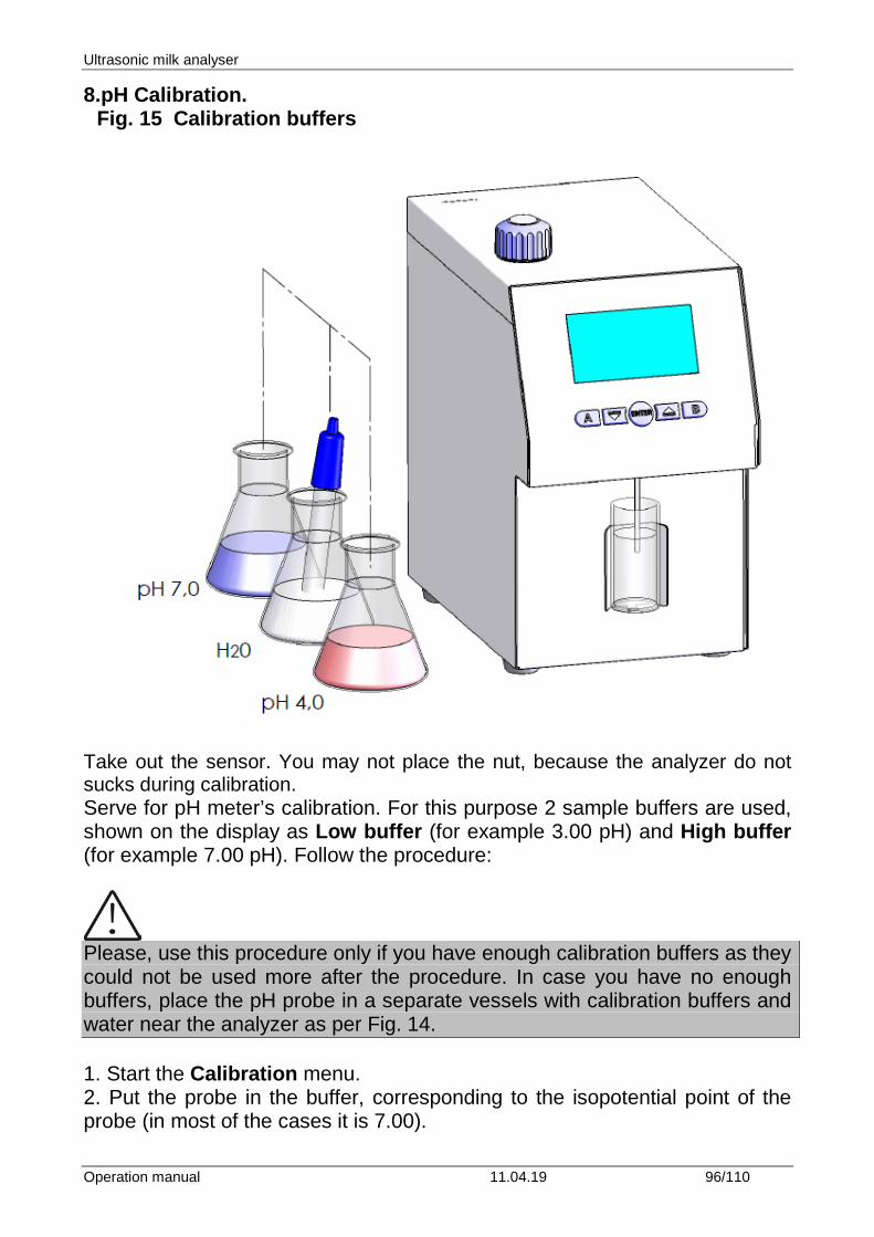
Ultrasonic milk analyser
Operation manual 11.04.19 96/110
8.pH Calibration. Fig. 15 Calibration buffers
Take out the sensor. You may not place the nut, because the analyzer do not sucks during calibration. Serve for pH meter’s calibration. For this purpose 2 sample buffers are used, shown on the display as Low buffer (for example 3.00 pH) and High buffer (for example 7.00 pH). Follow the procedure:
Please, use this procedure only if you have enough calibration buffers as they could not be used more after the procedure. In case you have no enough buffers, place the pH probe in a separate vessels with calibration buffers and water near the analyzer as per Fig. 14. 1. Start the Calibration menu. 2. Put the probe in the buffer, corresponding to the isopotential point of the probe (in most of the cases it is 7.00).
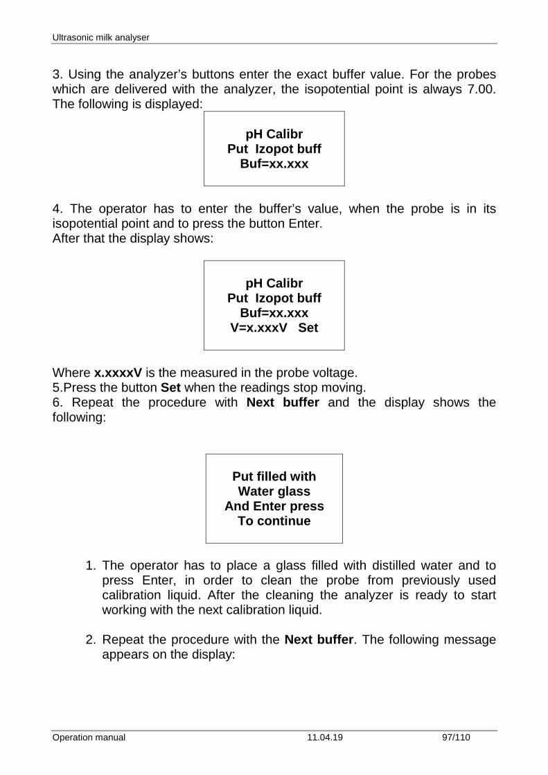
Ultrasonic milk analyser
Operation manual 11.04.19 97/110
3. Using the analyzer’s buttons enter the exact buffer value. For the probes which are delivered with the analyzer, the isopotential point is always 7.00. The following is displayed:
pH Calibr
Put Izopot buff Buf=xx.xxx
4. The operator has to enter the buffer’s value, when the probe is in its isopotential point and to press the button Enter. After that the display shows:
pH Calibr
Put Izopot buff Buf=xx.xxx
V=x.xxxV Set
Where x.xxxxV is the measured in the probe voltage. 5.Press the button Set when the readings stop moving. 6. Repeat the procedure with Next buffer and the display shows the following:
Put filled with Water glass
And Enter press To continue
1. The operator has to place a glass filled with distilled water and to press Enter, in order to clean the probe from previously used calibration liquid. After the cleaning the analyzer is ready to start working with the next calibration liquid.
2. Repeat the procedure with the Next buffer. The following message
appears on the display:
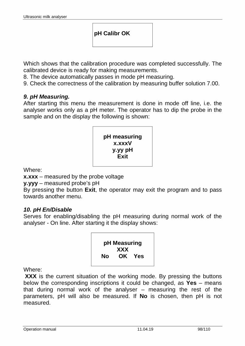
Ultrasonic milk analyser
Operation manual 11.04.19 98/110
pH Calibr OK
Which shows that the calibration procedure was completed successfully. The calibrated device is ready for making measurements. 8. The device automatically passes in mode pH measuring. 9. Check the correctness of the calibration by measuring buffer solution 7.00. 9. pH Measuring. After starting this menu the measurement is done in mode off line, i.e. the analyser works only as a pH meter. The operator has to dip the probe in the sample and on the display the following is shown:
pH measuring
x.xxxV y.yy pH
Exit
Where: x.xxx – measured by the probe voltage y.yyy – measured probe’s pH By pressing the button Exit, the operator may exit the program and to pass towards another menu. 10. pH En/Disable Serves for enabling/disabling the pH measuring during normal work of the analyser - On line. After starting it the display shows:
pH Measuring
XXX No OK Yes
Where: XXX is the current situation of the working mode. By pressing the buttons below the corresponding inscriptions it could be changed, as Yes – means that during normal work of the analyser – measuring the rest of the parameters, pH will also be measured. If No is chosen, then pH is not measured.
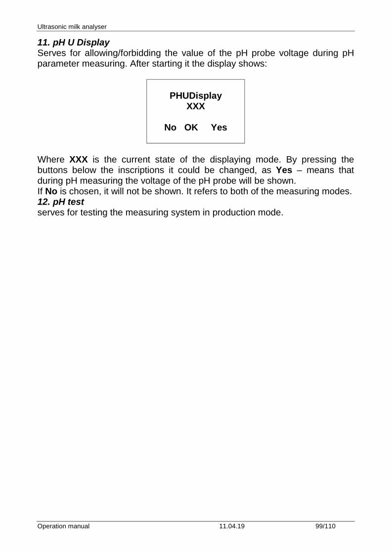
Ultrasonic milk analyser
Operation manual 11.04.19 99/110
11. pH U Display Serves for allowing/forbidding the value of the pH probe voltage during pH parameter measuring. After starting it the display shows:
PHUDisplay
XXX
No OK Yes
Where XXX is the current state of the displaying mode. By pressing the buttons below the inscriptions it could be changed, as Yes – means that during pH measuring the voltage of the pH probe will be shown. If No is chosen, it will not be shown. It refers to both of the measuring modes. 12. pH test serves for testing the measuring system in production mode.
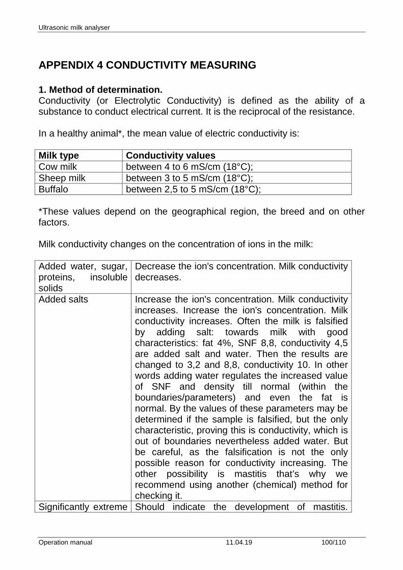
Ultrasonic milk analyser
Operation manual 11.04.19 100/110
APPENDIX 4 CONDUCTIVITY MEASURING 1. Method of determination. Conductivity (or Electrolytic Conductivity) is defined as the ability of a substance to conduct electrical current. It is the reciprocal of the resistance. In a healthy animal*, the mean value of electric conductivity is: Milk type Conductivity values Cow milk between 4 to 6 mS/cm (18°C); Sheep milk between 3 to 5 mS/cm (18°C); Buffalo between 2,5 to 5 mS/cm (18°C); *These values depend on the geographical region, the breed and on other factors. Milk conductivity changes on the concentration of ions in the milk: Added water, sugar, proteins, insoluble solids
Decrease the ion's concentration. Milk conductivity decreases.
Added salts Increase the ion's concentration. Milk conductivity increases. Increase the ion's concentration. Milk conductivity increases. Often the milk is falsified by adding salt: towards milk with good characteristics: fat 4%, SNF 8,8, conductivity 4,5 are added salt and water. Then the results are changed to 3,2 and 8,8, conductivity 10. In other words adding water regulates the increased value of SNF and density till normal (within the boundaries/parameters) and even the fat is normal. By the values of these parameters may be determined if the sample is falsified, but the only characteristic, proving this is conductivity, which is out of boundaries nevertheless added water. But be careful, as the falsification is not the only possible reason for conductivity increasing. The other possibility is mastitis that’s why we recommend using another (chemical) method for checking it.
Significantly extreme Should indicate the development of mastitis.
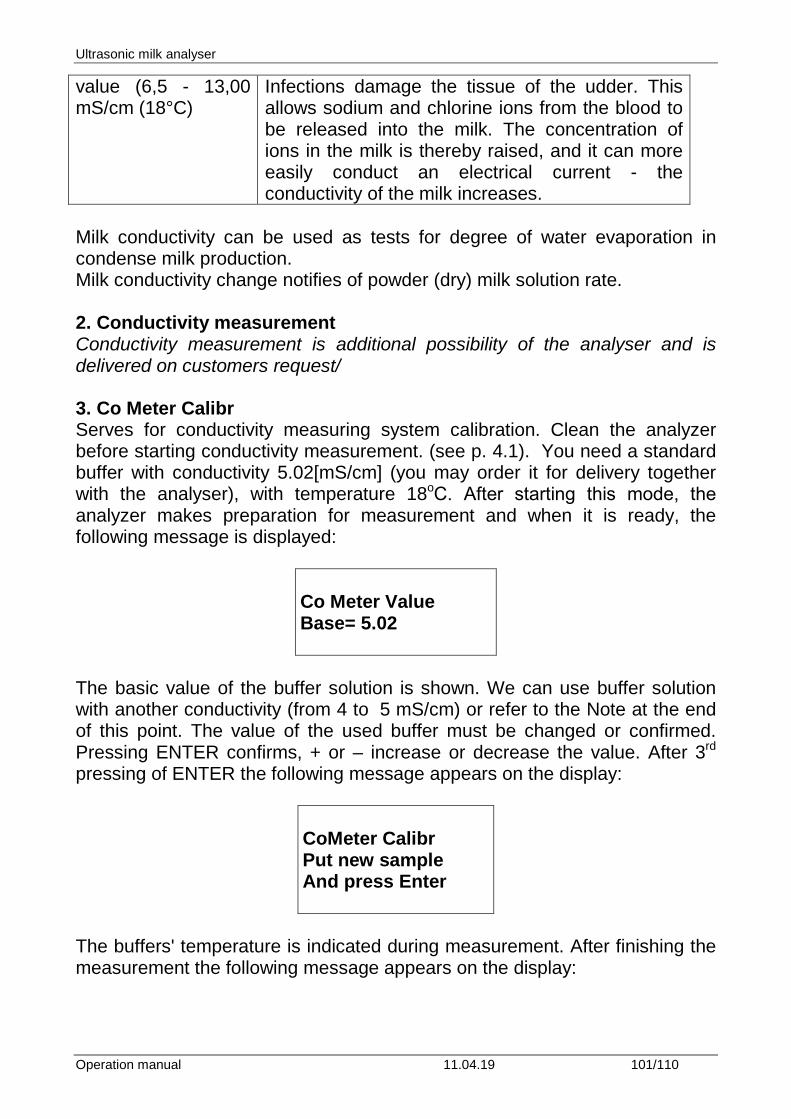
Ultrasonic milk analyser
Operation manual 11.04.19 101/110
value (6,5 - 13,00 mS/cm (18°C)
Infections damage the tissue of the udder. This allows sodium and chlorine ions from the blood to be released into the milk. The concentration of ions in the milk is thereby raised, and it can more easily conduct an electrical current - the conductivity of the milk increases.
Milk conductivity can be used as tests for degree of water evaporation in condense milk production. Milk conductivity change notifies of powder (dry) milk solution rate. 2. Conductivity measurement Conductivity measurement is additional possibility of the analyser and is delivered on customers request/ 3. Co Meter Calibr Serves for conductivity measuring system calibration. Clean the analyzer before starting conductivity measurement. (see p. 4.1). You need a standard buffer with conductivity 5.02[mS/cm] (you may order it for delivery together with the analyser), with temperature 18oС. After starting this mode, the analyzer makes preparation for measurement and when it is ready, the following message is displayed:
Co Meter Value Base= 5.02
The basic value of the buffer solution is shown. We can use buffer solution with another conductivity (from 4 to 5 mS/cm) or refer to the Note at the end of this point. The value of the used buffer must be changed or confirmed. Pressing ENTER confirms, + or – increase or decrease the value. After 3rd pressing of ENTER the following message appears on the display:
CoMeter Calibr Put new sample And press Enter
The buffers' temperature is indicated during measurement. After finishing the measurement the following message appears on the display:
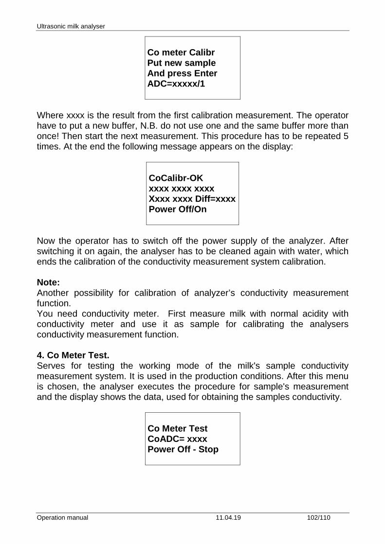
Ultrasonic milk analyser
Operation manual 11.04.19 102/110
Co meter Calibr Put new sample And press Enter ADC=xxxxx/1
Where xxxx is the result from the first calibration measurement. The operator have to put a new buffer, N.B. do not use one and the same buffer more than once! Then start the next measurement. This procedure has to be repeated 5 times. At the end the following message appears on the display:
CoCalibr-OK xxxx xxxx xxxx Xxxx xxxx Diff=xxxx Power Off/On
Now the operator has to switch off the power supply of the analyzer. After switching it on again, the analyser has to be cleaned again with water, which ends the calibration of the conductivity measurement system calibration. Note: Another possibility for calibration of analyzer’s conductivity measurement function. You need conductivity meter. First measure milk with normal acidity with conductivity meter and use it as sample for calibrating the analysers conductivity measurement function. 4. Co Meter Test. Serves for testing the working mode of the milk's sample conductivity measurement system. It is used in the production conditions. After this menu is chosen, the analyser executes the procedure for sample's measurement and the display shows the data, used for obtaining the samples conductivity.
Co Meter Test CoADC= xxxx Power Off - Stop
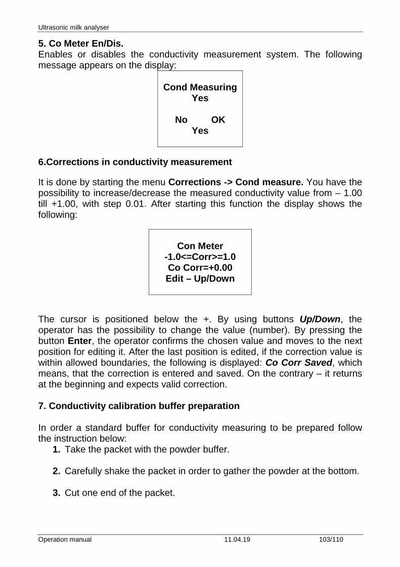
Ultrasonic milk analyser
Operation manual 11.04.19 103/110
5. Co Meter En/Dis. Enables or disables the conductivity measurement system. The following message appears on the display:
Cond Measuring
Yes
No OK Yes
6.Corrections in conductivity measurement It is done by starting the menu Corrections -> Cond measure. You have the possibility to increase/decrease the measured conductivity value from – 1.00 till +1.00, with step 0.01. After starting this function the display shows the following:
Con Meter
-1.0<=Corr>=1.0 Co Corr=+0.00 Edit – Up/Down
The cursor is positioned below the +. By using buttons Up/Down, the operator has the possibility to change the value (number). By pressing the button Enter, the operator confirms the chosen value and moves to the next position for editing it. After the last position is edited, if the correction value is within allowed boundaries, the following is displayed: Co Corr Saved, which means, that the correction is entered and saved. On the contrary – it returns at the beginning and expects valid correction. 7. Conductivity calibration buffer preparation In order a standard buffer for conductivity measuring to be prepared follow the instruction below:
1. Take the packet with the powder buffer. 2. Carefully shake the packet in order to gather the powder at the bottom.
3. Cut one end of the packet.
Ultrasonic milk analyser
Operation manual 11.04.19 104/110
4. Empty its content in a measuring mug with 1 l volume, paying attention all its content to be emptied.
For standard buffer: 5,02 ms – 3,056 г
5. Add 600-700 ml distilled water, which was preliminarily deaerated in
vacuum dryer or boiled and then cooled down to 20 ˚С. 6. Shake the mug till the powder is fully dissolved. 7. Add distilled water to the mark.
Ultrasonic milk analyser
Operation manual 11.04.19 105/110
Contents: 1. FUNCTION ............................................................................................................................................................. 6
2. TECHNICAL PARAMETERS ................................................................................................................................... 7
2.1. WORKING MODES CHARACTERISTICS: ........................................................................................................ 7 2.1.1. MEASUREMENT MODE MILK / DAIRY PRODUCT – FIRST TYPE ................................................................................ 7 2.1.2. MEASUREMENT MODE MILK / DAIRY PRODUCT – SECOND TYPE ............................................................................ 7 2.1.3. MEASUREMENT MODE UHT MILK / DAIRY PRODUCT – THIRD TYPE ...................................................................... 7 2.1.4. CLEANING ............................................................................................................................................................. 7
2.2. MEASURING RANGE: ............................................................................................................................................ 8
2.3. ACCURACY: ............................................................................................................................................................. 8
2.4 CORRECT AMBIENT CONDITIONS: .................................................................................................................. 9
2.5. DIMENSIONS: ……………………………..240/220/100 MM, MASS 3,0 KG ..................................................... 9
2.6. CONTINUOUS WORKING TIME: ………………………………………NON-STOP ....................................... 9
2.7 MILK SAMPLE VOLUME PER ONE MEASUREMENT: ………..15 CM3 (= 25 ML) .................................. 9
3. QUALIFICATION OF RAW MILK, THERMALLY TREATED MILK, OTHER DAIRY PRODUCTS AND DERIVATIVES .............................................................................................................................................................. 16
3.1. TAKING SAMPLES AND PREPARATION FOR ANALYSIS ......................................................................... 16
3.2. MAKING THE MEASUREMENT. ....................................................................................................................... 16 3.2.1. PREPARING THE ANALYZER FOR WORKING MODE ............................................................................................... 16 3.2.2. MAKING ANALYSIS ............................................................................................................................................. 17 3.2.3. DISPLAYING THE RESULTS .................................................................................................................................. 18
4. CLEANING THE ANALYZER ................................................................................................................................ 21
4.1. AUTOMATIC CLEANING THE ANALYZER ................................................................................................... 21 4.1.1. CURRENT CLEANING. .......................................................................................................................................... 23 4.1.2. END (FINAL) CLEANING. ...................................................................................................................................... 25
4.2. PREPARATION OF CLEANING SOLUTION ................................................................................................... 30 4.2.2. PREPARATION OF ACIDIC CLEANING SOLUTION ................................................................................................... 30
4.3. WORKING WITH THE PERISTALTIC PUMPS .............................................................................................. 32
5. POSSIBLE MALFUNCTIONS AND ERROR MESSAGES, TROUBLESHOOTING ..................................... 34
6. MAKING CORRECTIONS AND RECALLIBRATION OF THE DEVICE ....................................................... 35
6.1. TAKING SAMPLES AND PREPARATION OF SAMPLES FOR CHECKING THE ACCURRACY OF THE MILK ANALYSER, MAKING CORRECTIONS AND RECALIBRATION ................................................ 35
6.2. DETERMINATION THE TYPE OF THE DISCREPANCY: ............................................................................ 35 6.2.1. MAKING MEASUREMENTS ................................................................................................................................... 35 6.2.2. ANALYSING THE MEASUREMENT RESULTS .......................................................................................................... 35
6.3. MAKING CORRECTIONS ................................................................................................................................... 36 6.3.1. POSSIBLE CORRECTIONS, LIMITS AND CHANGING STEPS ...................................................................................... 36 6.3.2. PREPARING THE ANALYZER FOR MODE CORRECTIONS ........................................................................................ 37
Ultrasonic milk analyser
Operation manual 11.04.19 106/110
6.3.3. MAKING CORRECTION ......................................................................................................................................... 37
6.4. RECALIBRATING THE MILK ANALYSER ..................................................................................................... 39 6.4.1. RUNNING THE ANALYSER IN MODE RECALIBRATE .............................................................................................. 39 CHECKING THE CALIBRATION ....................................................................................................................................... 43
7. STARTING THE DEVICE IN A SERVICE TEST/SETUP OPERATIONAL MODE. MENUS DESIGNATION .............................................................................................................................................................. 45
7.1. STARTING THE DEVICE IN A SERVICE TEST/SETUP OPERATIONAL MODE. ................................... 45
7.2. MENUS FUNCTION: ............................................................................................................................................. 45 7.2.1. SPECIAL MODES. ................................................................................................................................................. 45 7.2.2. CORRECTIONS ..................................................................................................................................................... 46 7.2.3. SETTINGS. ........................................................................................................................................................... 46 7.2.4. TESTS. ................................................................................................................................................................. 51 7.2.6. EXIT .................................................................................................................................................................... 53
8. ENTERING DATA WITH THE KEYPAD AND PRINTING OUT THE RESULTS ......................................... 56 8.1. WORKING WITH THE KEYPAD ................................................................................................................................. 56 8.2. WORKING WITH THE PRINTER ................................................................................................................................ 57
8.2.1. Basic printer characteristics ......................................................................................................................... 57
FIG. 12 PRINTER CONTROL PANEL ...................................... ГРЕШКА! ПОКАЗАЛЕЦЪТ НЕ Е ДЕФИНИРАН.
8.2.2. Sequence of actions when printing ............................................... Грешка! Показалецът не е дефиниран.
9. ADDITIONAL POSSIBILITIES OF THE ANALYSER ........................................................................................ 60
9.1. CONNECTING TO 12 V DC POWER SUPPLY. ................................................................................................ 60
9.2. CONNECTING TO IBM PC .................................................................................................................................. 60
9.3. CONNECTING ADDITIONAL SERIAL PRINTER (OPTION). ...................................................................... 60
9.4. CONNECTING MATRIX PRINTER (OPTION). ............................................................................................... 60
9.5. MEASURING HIGH FAT SAMPLES (OPTION). .............................................................................................. 60
9.6. WORKING WITH EMBEDDED ACCUMULATOR (OPTION). ..................................................................... 61
9.7. AUTOMATIC WEIGHTING THE MILK WITH SCALES (OPTION). .......................................................... 63 9.7.1. PREPARATION FOR WORK AND CHECKING THE SCALES ....................................................................................... 63 9.7.2. WEIGHTING DELIVERED MILK. ............................................................................................................................ 63 9.7.3. CONTROL OPTIONS WHEN WORKING WITH SCALES. ............................................................................................. 65
9.8. WORKING WITH EMBEDDED REPORT SYSTEM FOR GENERATING AND MAKING REPORTS – REPORT SYSTEM (OPTION). .................................................................................................................................... 66
9.8.1.SETUP MENU STRUCTURE ..................................................................................................................................... 66 9.8.2. BASIC TERMS. ..................................................................................................................................................... 67 9.8.3. MENUS’ DESCRIPTION: ........................................................................................................................................ 68 9.8.4. REPORT OPTIONS: ............................................................................................................................................... 69 9.9. EMBEDDED REAL TIME CLOCK (OPTION). ............................................................................................................... 74 9.10. USB FLASH-DRIVE (PEN DRIVE) (OPTION). .......................................................................................................... 75
APPENDICES ................................................................................................................................................................. 78
APPENDIX 1: PREPARATION OF SAMPLES FOR MILKANALYSERS’ CALIBRATION ............................. 78
1. DETERMINATION SOME OF THE PARAMETERS BY FORMULAS ............................................................ 80 2. SNF DETERMINATION. .............................................................................................................................................. 80 3. DETERMINATION OF LACTOSE CONTENT ................................................................................................................... 80
Ultrasonic milk analyser
Operation manual 11.04.19 107/110
4. DETERMINATION OF SALTS CONTENT ........................................................................................................................ 81 5. DETERMINATION OF TOTAL PROTEINS CONTENT ....................................................................................................... 81
APPENDIX 2 FREEZING POINT DETERMINATION ........................................................................................... 83 1. METHODS FOR DETERMINATION. .............................................................................................................................. 83 2. THE BASIC FREEZING POINT. ..................................................................................................................................... 83
APPENDIX 3 PH MEASURING .................................................................................................................................. 86 1. GENERAL INFORMATION ........................................................................................................................................... 86 2. PH ELECTRODE ......................................................................................................................................................... 86
2.1. ELECTRODE PART .............................................................................................................................................. 86
2.2. ELECTRODE CARE & ELECTRODE MAINTENANCE ................................................................................ 86
2.3. STORAGE ................................................................................................................................................................ 86
2.4. AFTER USE ............................................................................................................................................................. 86
2.5. ELECTROLYTE REPLACEMENT (FOR REFILLABLE ELECTRODE ONLY). ....................................... 87
2.6. NEW ELECTROLYTE PREPARATION: ........................................................................................................... 87
2.7. RE-USE THE ELECTRODE. ................................................................................................................................ 87
2.8. ELECTRODE CLEANING .................................................................................................................................... 87
2.9. ELECTRODE ACTIVATION ............................................................................................................................... 88
2.10. REJUVENATION PROCEDURE ....................................................................................................................... 88
2.11. ELECTRODE LIFESPAN.................................................................................................................................... 88 3. BUFFER SOLUTIONS .................................................................................................................................................. 89 4. PH ELECTRODE CALIBRATION .................................................................................................................................. 89 5. PH HELPFUL HINTS ................................................................................................................................................... 90 6.PREPARATION FOR PH MEASUREMENT ....................................................................................................................... 91
FIG. 13 REMOVING THE STOPPER ......................................................................................................................... 92
FIG. 14 PLACING THE PROBE .................................................................................................................................. 93 7. PH MEASURING. ........................................................................................................................................................ 94 8.PH CALIBRATION. ...................................................................................................................................................... 96
FIG. 15 CALIBRATION BUFFERS ........................................................................................................................... 96 9. pH Measuring. .................................................................................................................................................... 98 10. pH En/Disable ................................................................................................................................................... 98 11. pH U Display .................................................................................................................................................... 99 12. pH test ............................................................................................................................................................... 99
APPENDIX 4 CONDUCTIVITY MEASURING ...................................................................................................... 100 1. METHOD OF DETERMINATION. ................................................................................................................................ 100
2. CONDUCTIVITY MEASUREMENT .................................................................................................................... 101
3. CO METER CALIBR .............................................................................................................................................. 101
4. CO METER TEST. .................................................................................................................................................. 102
5. CO METER EN/DIS. ............................................................................................................................................... 103
6.CORRECTIONS IN CONDUCTIVITY MEASUREMENT ................................................................................. 103
Ultrasonic milk analyser
Operation manual 11.04.19 108/110
7. CONDUCTIVITY CALIBRATION BUFFER PREPARATION ........................................................................ 103
CONTENTS: ................................................................................................................................................................. 105
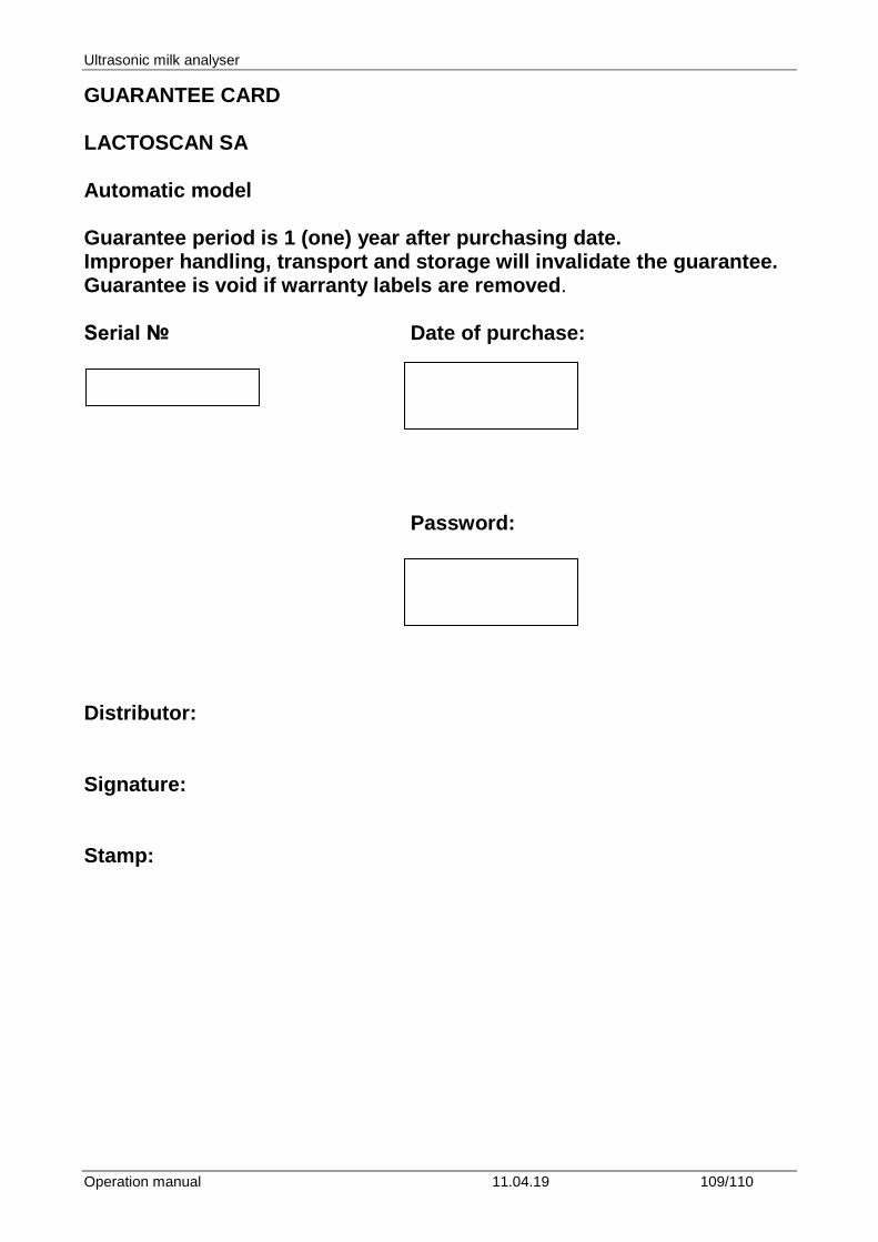
Ultrasonic milk analyser
Operation manual 11.04.19 109/110
GUARANTEE CARD LACTOSCAN SA Automatic model Guarantee period is 1 (one) year after purchasing date. Improper handling, transport and storage will invalidate the guarantee. Guarantee is void if warranty labels are removed. Serial № Date of purchase:
Password:
Distributor: Signature: Stamp:
Ultrasonic milk analyser
Operation manual 11.04.19 110/110
GUARANTEE CARD Purchaser: Service report:
Service entry date Damage Delivery
date Signature
Covers: Lactoscan SA Last edited: 29.03.2019 HEAD OFFICE: 4, Narodni Buditeli Str. 8900 Nova Zagora BULGARIA Phone/Fax: + 359 457 67082 E-mail: [email protected] www.lactoscan.com www.milkotronic.com