construction stormwater management plan for grand valley
TRANSCRIPT

Grand Valley Storage CSWMP (SW22-0041) Page 1 of 18 January 17, 2022
Construction Stormwater Management Plan
For Grand Valley Storage
January 6, 2022
Revised (January 17, 2022)
Introduction
This CSWMP for Grand Valley Storage is formatted and presented consistent with Mesa County SWMM and State of
Colorado 4000 series stormwater permit criteria, and local guidance provided by Mesa County Stormwater. There are no
exceptions to State required inclusions in the plan. The following CSWMP is organized and presented as follows:
Section 1: Site Description
Section 2: Site Map (Stormwater Control Measures map included in Appendix A)
Section 3: Stormwater Management Controls
Section 4: Final Stabilization
Section 5: Inspection and Maintenance Procedures
Appendix A: Stormwater Control Measures Map
Appendix B: Mesa County Stormwater Inspection Report Template
Appendix C: Best Management Practice (Stormwater Control Measures) Details
This CSWMP was prepared by Courtney Patch of River City Consultants, Inc. 215 Pitkin Ave. #201, Grand Junction, CO
81501. SWMP availability shall be as per Part I.C.4. A copy of this plan shall be made available upon request. This plan
shall be updated with changes and modifications by the SWMP Administrator or someone designated to make changes
by them. In addition to this plan the following materials shall also be available for review:
• Stormwater Control Measure Map (with mark-ups to reflect on-site conditions)
• Copies of completed Inspection Reports
This plan and the materials above should be made available to the public for viewing upon request. Appendix B has a
generic sign-in sheet that can be used for Project Meeting and Training documentation.

Grand Valley Storage CSWMP (SW22-0041) Page 2 of 18 January 17, 2022
1. Site Description
a) The nature of the construction activity at the site. The description should include the physical location and address or cross streets, type of project, a summary of the grading activities, installation of utilities, paving, excavation, landscaping, and the final disposition of the property.
The project site is located at 1930 Highway 6 & 50, Fruita, CO 81521, which is approximately 16.8 acres. The site
is on the north of Highway 6 & 50, west of 19 ½ Rd. In more legal terms: S ¼, Section 22, Township 1 North,
Range 2 West of the Ute Meridian, Mesa County, Colorado. The parcel number for this project is 2697-223-00-
073. The proposed development includes a minor subdivision and a site plan review for a storage facility. The
subdivision will create one new lot out of the parent parcel (two lots total). The storage facility will be located
on Lot 1 which will consist of 7.157 acres. Lot 2 will not be disturbed at this time, other than the detention pond
will be in the southwest corner. The parcel is zoned C-1 and within the city limits of Fruita.
The parcel is surrounded by vacant land, and single-family homes with larger lot sizes to the north zoned AFT
and within the jurisdiction of Mesa County. Directly south of the parcel is Highway 6 & 50 and to the east and
west are large lot commercial parcels within the city limits of Fruita, zoned C-1. To the northwest there are
residential parcels zoned Rural Estate.
The current project parcel is approximately 16.8 acres of agricultural land and one single-family home. The
existing house is to be removed, and approximately 4.5 acres of Lot 1 will be developed.
Construction activities will consist of: installation of streets, curb, gutter, and sidewalk, utility installation
(water, sewer, storm drain, and various dry utilities), construction of industrial building units, various grading
activities, and landscaping/restoration.
b) The proposed sequence for major activities. Describe the sequence of events involved in the construction project, such as grading, excavation, final landscaping, etc.
1. File N.O.I;
2. Pre-construction meeting;
3. Install perimeter controls (earthen dikes, sediment control logs (wattles), silt fence, filter berms, etc.);
4. Access stabilization (vehicle tracking control, surface hardening, etc.);
5. Sediment control (rock socks, surface roughening, etc.).
6. Storm water controls (earthen dikes and drainage swales, inlet protection (e.g., Dandy Bags), outlet
protection, etc.);
7. Grading (to be phased such that disturbed area is minimized). Install additional controls as required due
to phasing, construction methodology, site conditions, etc. (controls include additional perimeter
controls, surface roughening, surface hardening, etc.);
8. Utility Installation (to be phased with grading and other construction activities);
9. Stabilize disturbed areas as soon as possible after construction to prevent erosion (temporary seeding,
surface roughening, surface hardening, etc.);
10. Building construction (relocate controls or install additional controls as necessary);
11. Final stabilization (surface hardening (roofs, concrete, & asphalt), landscaping, permanent
seeding/planting, etc.);
12. Remove temporary stormwater control measures after construction activities are complete and ground
cover has been established to 70% of pre-construction conditions via vegetation, landscaping, surface
hardening, or a combination there of; and

Grand Valley Storage CSWMP (SW22-0041) Page 3 of 18 January 17, 2022
13. File N.O.T.
Note this process will be repeated for each construction phase.
c) Estimates of the total area of the site, and the area and location expected to be disturbed by clearing, excavation, grading, or other construction activities.
The full parcel is listed as 16.8 acres, of which approximately 4.5 acres will be disturbed during construction of
Grand Valley Storage.
d) A summary of any existing data used in the development of the site construction plans or SWMP that describe the soil or existing potential for soil erosion.
According to the NRCS web site, the soils present at the entire site consist of approximately 10% Sagers silty clay
loam with 0-2% slopes, approximately 10 % Turley clay loam with 0-2% slopes, and approximately 80%
Fruitland sandy clay loam with 0-2% slopes. These soils are classified as Hydrologic Soil Group B and C. Group C
soils have slower infiltration rates than Groups A and B Soils.
The Whole Soil K Factor is 0.43 for Sagers silty clay loam soils, 0.17 for Fruitland sandy clay loam soils, and 0.28
for Truly clay loam soils. The K factor indicates the susceptibility of a soil to sheet and rill erosion by water. K
values range from 0.02 to 0.69 and other factors being equal, the higher the K factor value, the more
susceptible the soil is to sheet and rill erosion by water. NRCS Soil information for the site is provided in
Appendix D.
e) A description of the existing vegetation at the site and an estimate of the percent vegetative ground cover.
Pre-design site visits show that existing topography at the site consistently slopes from north to south with
typical grades between 0-2%. Existing vegetation at the proposed project site consists of agricultural fields by
visual estimation. Existing vegetation is in good condition (~80% ground cover).
f) The location and description of all potential pollution sources, including ground surface disturbing activities, vehicle fueling, storage of fertilizers or chemicals, etc.
Pollutant Potential Sources Stormwater Control Measures for Pollutant
Sediment Erosion of exposed soil, dust, drainages,
stockpiles, vehicle tracking, etc.
Sediment Control Log, Earthen Dike,
Surface Hardening, Surface Roughening,
Rock Socks, Inlet & Outlet protection,
Street Sweeping, etc.
Toxic Chemicals Poor storage and handling of materials,
spills, illegal dumping, pesticide application,
etc.
Handling and storage as per
Manufacturer’s recommendations, Spill
Prevention, Control, and Counter
Measures
Bacteria Leaking septic/sewer systems, pet & wildlife
waste, illicit connections to storm drain
system, etc.
Port-a-potties and bathrooms; Spill
Prevention, Control, and Counter
Measures
Nutrients Fertilizers, leaking septic/sewer, decaying
plant and animal waste, etc.
Handling, storage, and application as per
Manufacturer’s recommendations; Spill
Prevention, Control, and Counter
Measures

Grand Valley Storage CSWMP (SW22-0041) Page 4 of 18 January 17, 2022
Oxygen Demand Sediment, nutrients, organics, and other
pollutants (particulates and soluble)
See Stormwater Control Measures for
pollutants above
Fuels, Oils, and
Greases
Streets, highways, parking lots, equipment
fueling & maintenance, illegal dumping,
atmospheric deposition etc.
Spill Prevention, Control, and Counter
Measures
Litter/Trash Human Activities Good Housekeeping
Metals Streets, highways, parking lots, building
materials, recyclable materials, industrial
activities, atmospheric deposition, etc.
Street sweeping, Material Handling and
Storage as per Manufacturer’s
recommendations, Spill Prevention,
Control, and Counter Measures
Elevated Water
Temperatures
Sunlight, removal of vegetation,
impervious areas, shallow storage of
water, etc.
Proper maintenance of Stormwater
Control Measures
Concrete and waste-
water wash-out
Washing out of concrete trucks, concrete
tools (including stucco), drywall, paint, etc.
Installation & use of a wash-out area
g) The location and description of any anticipated allowable sources of non-stormwater discharge at the site. (e.g., uncontaminated springs, landscape irrigation return flow, construction dewatering, and washout)
Allowable non-stormwater discharges to SWMP:
o Discharges from diversions of State waters within the permitted site.
o Discharges from Emergency Fire Fighting Activities.
The project parcel is currently in the Grand Valley Irrigation District. This parcel is currently being irrigated with
10 shares of water to be divided between the two parcels. Lot 1 will only need to irrigate the common
landscaped area in front along the street frontage, but Lot 2 will continue to be farmed until further
development occurs in the future.
There are no known springs on-site. A concrete washout will be installed on-site. The concrete washout will be
installed as per the UDFC detail included in this plan, signed, and used as needed by concrete suppliers.
As per Part I.A.1 authorized discharges include stormwater associated with construction, including masonry
mixing stations, and washout water associated with construction as long as discharge is to a washout or
alternative area authorized by the State Permit and said water does not leave the site as surface runoff.
h) The name of the receiving water(s) and the size, type and location of any outfall(s). If the stormwater discharge is to a municipal separate storm sewer system, the name of that system, the location of the storm sewer discharge, and the ultimate receiving water(s).
The Grand Valley Storage project is within the Mesa County (MS4) boundary and will discharge to its historical
point located in the southwest corner of the property along with piping to a tailwater ditch that runs to the
southwest. The ultimate receiving water is the Colorado River approximately 1 mile southwest of the property.
i) The plan site description must include a description of all stream crossings located within the construction site boundary (I.C2.vi.h.).
There are no stream crossings at this site.

Grand Valley Storage CSWMP (SW22-0041) Page 5 of 18 January 17, 2022
2. Stormwater Control Measure Map
The SWMP must include a site map showing the entire area and identifying the following components (I.C.2.vii.):
a) Construction site boundaries;
See construction site boundary shown on map.
b) All areas of ground surface disturbance;
See perimeter controls shown on map.
c) Areas of cut and fill;
See existing and proposed contours on map.
d) Areas used for storage of building materials, equipment, soil, or waste;
These areas have been designated on the map.
e) Locations of dedicated asphalt or concrete batch plants;
None of these facilities will be located on-site for this project.
f) Locations of all structural stormwater control measures;
See map for stormwater control measures locations.
g) Locations of non-structural stormwater control measures as applicable; and
See map for stormwater control measures locations.
h) Locations of springs, streams, stream crossings, wetlands and other surface waters.
See map for locations. i) The plan site map must include flow arrows that depict stormwater flow directions on-site and runoff direction.
See map for flow arrows. i) The plan site map must include areas that require pre-existing vegetation to be maintained within 50 feet of a receiving water, where feasible.
See map for vegetative buffers.
3. Stormwater Management Controls
The SWMP must include a description of all stormwater management controls that will be implemented as part of the construction activity to control pollutants in stormwater discharges. The appropriateness and priorities of stormwater management controls in the SWMP shall reflect the potential pollutant sources identified at the facility. The description of the stormwater management controls shall address the following, at a minimum:
a) Qualified Stormwater Manager(s) - The SWMP shall identify a specific individual or individuals for the site. This is an individual knowledgeable in the principles and practices of erosion and sediment control and pollution prevention, and with the skills to assess conditions at construction sites that could impact stormwater quality and to assess the effectiveness of stormwater controls implemented to meet the requirements of this permit (I.C.2.a.i.).
Qualified Stormwater Manager for Design:
Courtney Patch – River City Consultants, Inc.
(970)241-4722 or [email protected]
b) Identification of Potential Pollution Sources- All potential pollutant sources, including materials and activities, at a site must be evaluated for the potential to contribute pollutants to stormwater discharges. The SWMP shall identify and describe those sources determined to have the potential to contribute pollutants to stormwater discharges, and the sources must be controlled through stormwater control measures selection and implementation, as required in paragraph (c) below. At a minimum each of the following sources and activities

Grand Valley Storage CSWMP (SW22-0041) Page 6 of 18 January 17, 2022
shall be evaluated for the potential to contribute pollutants to stormwater discharges, and identified in the SWMP if found to have such potential:
Please refer to Section 1.f above. The main pollutant sources for this project are:
1. Disturbed soil – main potential pollutant sediment – stormwater control measures include, but are not
limited to: surface roughening, surface hardening, earthen dike/drainage swale, sediment control logs, silt
fence, rock socks, vehicle tracking control, street sweeping, etc.
2. Concrete - washout and cleanup waste & wastewater - stormwater control measure is the washout
3. Trash – worker and project generated trash – stormwater control measure is good housekeeping
4. Masonry Mixing Stations – material spillage and washout waste – stormwater control measure is secondary
containment around all mixing stations and the washout. Masonry materials that end up on the ground
outside of the secondary containment and in areas that drain offsite must be picked up and properly
disposed of (i.e., placed in a roll-off container).
1) all disturbed and stored soils;
Please refer to Section 1.f above. Phase grading to minimize the disturbed area at all times. As soon as possible
after completion of grading activities, all disturbed areas will be stabilized. Stabilization may be by any of the
following: surface hardening (asphalt, concrete, roof, etc.), landscaping, seeding (permanent or temporary),
surface roughening, mulching, or other acceptable method (as long as an installation & maintenance detail for
said method is added to the appendix of this report).
Disturbed areas of the construction site that will not be re-disturbed for 14 days or more must be stabilized (as
noted above) by the 14th day after the last disturbance. If construction is suspended, or sections completed,
stabilized areas must be protected to the extent possible.
Soil and aggregate stockpiles shall have a sediment control stormwater control measure downslope of the pile.
The stormwater control measure does not need to be specific to the stockpile, if the stockpile is within perimeter
controls then the downstream perimeter controls will suffice. Typical stormwater control measures include
earthen dike/drainage swale or sediment control log. Storage areas should be outside of concentrated drainage
pathways to the extent possible.
2) vehicle tracking of sediments;
Please refer to Section 1.f above.
Vehicle tracking control (VTC) or stabilized entryways (SEW) will be installed at entrances/exits between
stabilized and unstabilized areas. A detail for the vehicle tracking control and stabilized entry-way stormwater
control measure can be found in Appendix C.
If VTC or SEW are not practical to use or install than another stormwater control measure or other stormwater
control measures will be used such street cleanup/sweeping. Street cleanup and sweeping may be required even
if VTC and SEW are used if significant vehicle tracking of sediments occurs. Street cleanup/sweeping will remove
tracked sediment and materials from internal and/or adjacent streets before they come into contact with
stormwater or enter the storm drain system. Street cleanup/sweeping should be performed any time visible
removable amounts of soil or material is present on the streets. Swept up material shall be properly disposed of
at a facility accepting said waste.

Grand Valley Storage CSWMP (SW22-0041) Page 7 of 18 January 17, 2022
3) management of contaminated soils;
Please refer to Section 1.f above.
All federal (e.g., EPA, OSHA), state, and local regulations and laws apply. Proper training, notification, PPE,
procedures, handling, disposal, etc. are the responsibility of the General Contractor. Further it is the General
Contractor’s responsibility to ensure all sub-contractors are properly trained and follow said rules and
regulations (including, but certainly not limited to this plan).
In the event of a spill the proper authorities shall be notified immediately, work shall stop in the immediate area
of the spill, and the MSDS for that material should be consulted for health and safety, containment, and cleanup
procedures. The spill will be properly cleaned up by qualified personnel and disposed of properly. A paper trail
will document the entire proceeding and all applicable regulations and/or laws will be followed and adhered to.
4) loading and unloading operations;
Please refer to Section 1.f above.
Loading and unloading shall occur in low traffic areas. Flaggers and spotters should be used as needed or if
loading or unloading must be done in an area with traffic. When possible do not work around overhead lines
(i.e., power). If working around overhead lines use a spotter. Storage areas should be located outside of
concentrated drainage pathways (see Stormwater Control Measure Map for locations).
5) outdoor storage activities (building materials, fertilizers, chemicals, etc.
Please refer to Section 1.f above.
Non-toxic building materials can be stored outside uncovered. Toxic materials (chemicals, paints, fertilizers, etc.) covered storage shall be used whenever possible (i.e., inside of the building under construction or under a tarp) and under the conditions noted on the MSDS and/or by the manufacture. If covered storage is not available then storage shall be in an area where runoff from that area is retained (e.g., bermed area, or depressed area). All storage areas should be located outside of concentrated drainage pathways.
6) vehicle and equipment maintenance and fueling;
Prior to site entry equipment shall be cleaned, free of leaks, and in good working condition. Equipment left on-site shall be stored on compacted (mostly) level ground. Prior to leaving the site equipment should be “gross cleaned”. Gross cleaning shall include removal of loose and caked on soil or other material prior to loading with a shovel and/or broom. Fueling of equipment shall occur on compacted level ground. The fueling truck and equipment being fueled shall be blocked and parking brake/lock-out applied during fueling. A spill kit shall be present on the fuel truck at all times when the truck is on-site and the operator of the fuel truck shall be trained and knowledgeable in the spill kits use. Only minor maintenance (greasing, minor adjustments, etc.) of equipment shall be performed on site. NO maintenance with the potential for a reportable spill is to be conducted on-site. The exception to this rule is fixing a piece of equipment to a point so it can be transported off-site and fixed.
7) significant dust or particulate generating processes;
The Contractor shall have a water truck or other acceptable method available for wetting soils and preventing airborne sediment transport via dust. The water truck does not necessarily need to be on-site, but it must be available to use if it is needed.
8) routine maintenance activities involving fertilizers, pesticides, detergents, fuels, solvents, oils, etc.;
These activities shall follow the SPCC guidelines below. Please note when using the procedure below it is still the Contractor’s complete responsibility to ensure compliance with local, State, and Federal

Grand Valley Storage CSWMP (SW22-0041) Page 8 of 18 January 17, 2022
Regulations regarding spills, employee training, hazard communication, and health and safety. By using the below procedure, the Contractor implies that they agree to absolve River City Consultants, Inc. of any and all potential liability associated with using said procedures. Generic SPCC: 1. Store all materials (hazardous and non-hazardous) according to manufacturer’s recommendations
and standard practice. This includes toxic chemicals, fertilizers, building materials/supplies, equipment, material stockpiles, etc.
2. Keep Material Safety Data Sheets (MSDS’s) as required by various regulations. 3. Train employees as required by various regulations (e.g., HAZCOMM and spill recognition). 4. The contractor will be responsible for all cleanup activities in accordance with applicable local,
state, and federal regulations. 5. Upon discovery of a spill:
a. Survey the area for danger. Leave area immediately if a danger or hazard is present or perceived to be present and call 911 from a safe location.
b. Any of the steps below assume there are no dangers or hazards. If a hazard or danger is identified, perceived, or discovered at any point immediately leave the area and get to a safe location/distance and call 911.
c. Identify the source of the spill. d. Determine if the source and be safely “turned off” or stopped. e. Do you have the proper training and/or PPE to safely and correctly stop the source of the
spill? If no, call 911. If you do then follow proper procedure and stop the source of the spill, then call 911.
f. If it is safe to do so and you have proper training, you may attempt to contain the spill and prevent it from reaching/spreading to any water body, storm drain, or off-site.
g. Notify your supervisor. The supervisor should contact all appropriate agencies and personnel (e.g., Regulators, Cleanup Contractor, Owner/Client, etc.). In most instances the CDPHE must be contacted within 24-hours (1-877-518-5608).
h. Notify Mesa County Stormwater Division of a spill or discharge the enters the MS4 at the Hotline: (970)263-8201.
i. Any required spill reporting or spill logs should be completed as soon as possible and submitted or kept on record as required by regulations.
j. Materials and equipment needed for cleanup procedures (“spill kits”) will be kept readily available on the site, either at an equipment storage area or on contractor’s trucks. Equipment to be kept on the site may include but is not limited to brooms, dust pans, shovels, granular absorbents, sand, sawdust, absorbent pads and socks, plastic and metal trash containers, gloves, and safety glasses.
9) on-site waste management practices (waste piles, liquid wastes, dumpsters, etc.);
See the Good Housekeeping stormwater control measure detail in Appendix C. Re-use and recycle whenever possible. Salvage and recycle bins and/or containers should be used if the supply of recyclable materials warrants their use. Recyclable containers/bins should be covered during non-working hours. Covers will prevent materials from blowing out of the containers and stormwater from contacting the materials within the containers. Trash containers, dumpsters, and/or roll-offs should be located on-site in easy to access locations. Trash containers need to be covered or weighted down to avoid debris from blowing out and littering the site. A local company specializing in the collection and disposal of said waste material will be utilized and their responsibilities will include supplying and resupplying the site with containers, removing full containers from the site, proper transport and disposal of waste material to a facility accepting said waste.

Grand Valley Storage CSWMP (SW22-0041) Page 9 of 18 January 17, 2022
Liquid wastes should not be placed in trash containers with “weep holes” that would allow the liquid wastes to leak/spill out of the container and onto the ground. Also do not dispose of liquid wastes down storm drains or via the sanitary sewer. Do dispose of liquid wastes according to Manufacture’s recommendations acceptable standard practice, and all local, state, and federal regulations. The Contractor shall perform good housekeeping practices. Garbage and construction waste shall be cleaned up and disposed of on a regular basis (at least once a week). If garbage or construction debris is blown off-site during a windy day it is the Contractor’s responsibility to retrieve and dispose of said materials. Port-a-potties for human waste will be located on-site as shown on the Stormwater Control Measure Map. These will be provided and maintained by a local company specializing in the port-a-potty business. Their responsibilities will include supply, cleaning, and maintenance of the port-a-potties, and proper disposal to a facility accepting said waste. Port-a-potties shall be staked or otherwise secured to prevent accidental tipping due to wind or other cause and located within the controlled area.
10) concrete truck/equipment washing, including concrete truck chute and associated fixtures and equipment;
A washout shall be installed on-site as per the detail in Appendix C. This washout shall be used for concrete, paint, stucco, spackle, and any other liquid or washout waste generated onsite. Note: washout water shall not be discharged to state surface waters or to storm sewer systems. On-site permanent disposal of washout waste is not authorized. Washout can be excavated as per MHFD detail or proprietary device such as Outpak or another suitable washout container. Discharge of washout waste in the designated washout area, foundation excavation, or other fully contained area where concrete will be placed is permitted as long as that material will subsequently be disposed of off-site is authorized.
11) dedicated asphalt and concrete batch plants;
No asphalt or concrete batch plants will be built on-site for this project.
12) non-industrial waste sources such as worker trash and portable toilets;
Please refer to 3.b.9 above.
13) other areas or procedures where potential spills can occur.
Please refer to 3.b.8 above. Driller’s mud for foundation piles can be placed within the foundation excavation as long as the excavation is depressed and will contain said waters (i.e., they cannot leave the foundation excavation area). Driller’s mud can be discharged to the washout. Driller’s mud cannot be discharged directly to the ground outside of the limits of the foundation excavation.
c) Best Management Practices. The SWMP shall identify and describe appropriate stormwater control measures, including, but not limited to, those required by paragraphs 1 through 8 below, that will be implemented at the facility to reduce the potential of the sources identified in part b, above, to contribute pollutants to stormwater discharges. The SWMP shall clearly describe the installation and implementation specifications for each stormwater control measure identified in the SWMP to ensure proper implementation, operation, and maintenance of the stormwater control measure. If any offsite stormwater control measures are utilized, the plan must include a documented use agreement between the permittee and the owner or operator of any control measures located outside of the permitted area, that are utilized by the permittee’s construction site for compliance with the Construction Stormwater Permit, but not under the direct control of the permittee. The plan must also include design specifications for these control measures (I.C.2.v)
1. Structural Practices for Erosion Control. The SWMP shall clearly describe and locate all structural practices

Grand Valley Storage CSWMP (SW22-0041) Page 10 of 18 January 17, 2022
implemented at the site to minimize erosion and sediment transport. Practices may include, but are not limited to: straw bales, wattles/sediment control logs, silt fences, earth dikes, drainage swales, sediment traps, subsurface drains, pipe slope drains, inlet protection, outlet protection, gabions, and temporary or permanent sediment basins.
Please refer to the Stormwater Control Measure Map in Appendix A of this plan. Appendix C of this plan contains the installation details for all of the stormwater control measures listed within the report and on the stormwater control measure Map. CSWM Plan Enhancement This plan is intended to be a “living document” and it is expected that it will be modified and updated throughout the project. The purpose of these changes is to continuously improve and tailor the plan to the project and to ensure the plan and field conditions match. These modifications/updates will be documented in writing within the copy of the original plan located on-site as per Part I.C.3 of the Permit.
2) Non-Structural Practices for Erosion and Sediment Control. The SWMP shall clearly describe and locate, as applicable, all non-structural practices implemented at the site to minimize erosion and sediment transport. Description must include interim and permanent stabilization practices, and site-specific scheduling for implementation of the practices. The SWMP should include practices to ensure that existing vegetation is preserved where possible. Non-structural practices may include, but are not limited to: temporary vegetation, permanent vegetation, mulching, geotextiles, sod stabilization, slope roughening, vegetative buffer strips, protection of trees, and preservation of mature vegetation.
Please refer to the Stormwater Control Measure Map in Appendix A of this plan. Appendix C of this plan contains the installation details for all of the stormwater control measures listed within the report and on the Stormwater Control Measure Map. Education/Training The purpose of this plan is not to hinder or interfere with the progression of work on this project, but instead to improve, complement, and enhance the overall outcome of this project. People working on-site are encouraged to read this plan. These workers may have suggestions based on their experience at other sites and projects. These suggestions should be brought to the attention of the SWMP Administrator, who may (at their discretion) modify this plan accordingly.
3) Phased Stormwater Control Measure Implementation: The SWMP shall clearly describe the relationship between the phases of construction, and the implementation and maintenance of both structural and non-structural stormwater management controls. The SWMP must identify the stormwater management controls to be implemented during the project phases, which can include, but are not limited to, clearing and grubbing; road construction; utility and infrastructure installation; vertical construction; final grading; and final stabilization.
Stormwater pollution prevention measures can be categorized as follows: 1. Preventing contact between stormwater and the pollutant. 2. Preventing transport of the pollutant by stormwater. 3. Treatment to remove pollutants from stormwater.
These measures are listed in order according to effectiveness and priority. Obviously if the stormwater does not come into contact with a pollutant, it cannot become contaminated with the pollutant. Second, if the stormwater contacts the pollutant and the pollutant does not suspend or dissolve into the stormwater, the stormwater will remain uncontaminated. The best way to protect the soil surface and limit erosion is to preserve existing vegetative cover. Unfortunately, even with our best efforts stormwater will likely become contaminated with pollutants from the site. This is because by nature of the project portions of the site will be disturbed. Accordingly, efforts will be put in place to facilitate the removal of some of these pollutants from stormwater. This is especially true prior to discharge from the site, but most effective if done in series to ensure the pollutant levels never reach high levels and so the perimeter controls are not the only defense, but instead the last line of defense.
Grand Valley Storage CSWMP (SW22-0041) Page 11 of 18 January 17, 2022
The construction activities will be structured to minimize the total area disturbed at any one time. Perimeter and outfalls stormwater control measures, access stabilization will be installed prior to soil disturbance. Internal sediment and stormwater controls will be installed as grading and disturbance activities proceed. These internal controls will be shifted as new areas are disturbed and other areas are stabilized. It will be the SWMP Administrator’s job/responsibility to document any changes to the location and type of stormwater control measures used and to keep this plan up to date.
4) Materials Handling and Spill Prevention. The SWMP shall clearly describe and locate all practices implemented at the site to minimize impacts from procedures or significant materials that could contribute pollutants to runoff. Such procedures or significant materials could include: exposed storage of building materials; paints and solvents; fertilizers or chemicals; waste material; and equipment maintenance or fueling procedures. Areas or procedures where potential spills can occur must have spill prevention and response procedures identified in the SWMP.
As previously stated, materials will be handled according to their MSDS sheets and/or Manufacturer’s recommendations. The Contractor should have a Spill Prevention, Control, and Countermeasure Plan (SPCC Plan). Please refer to Section 3.b.8 for generic Spill Prevention, Control, and Countermeasures in the absence of said plan. Please refer to the procedures described in Section 3.b and other areas of this report for the specifics of dealing with potential contaminates on this site.
5) Dedicated Concrete or Asphalt Batch Plants and Masonry Mixing Stations. The SWMP shall clearly describe and locate all practices implemented at the site to control stormwater pollution from dedicated concrete batch plants or dedicated asphalt batch plants covered by this certification.
No concrete or asphalt batch plants will be implemented at the site. Masonry mixing stations located onsite
need to have secondary containment that will prevent any spilled material or water from leaving the mixing
station area. Secondary containment can be an earthen berm, sand bags or rock socks, or a properly installed
sediment control log. The secondary containment area and any spilled materials shall be cleaned up and
properly disposed of once the mixing station is no longer in use.
6) Vehicle Tracking Control. The SWMP shall clearly describe and locate all practices implemented at the site to control potential sediment discharges from vehicle tracking. Practices must be implemented for all areas of potential vehicle tracking, and can include: minimizing site access; street sweeping or scraping; tracking pads; graveled parking areas; requiring that vehicles stay on paved areas on-site; wash racks; contractor education; and/or sediment control stormwater control measures, etc.
Vehicle tracking control will be installed at entrances/exits between stabilized and unstabilized areas when possible or practical. A detail for the vehicle tracking control can be found in Appendix C. If VTC is not practical than an alternate stormwater control measures must be used such as stabilized entryway or street sweeping/cleaning. Even with the use of VTC street sweeping may be required if significant vehicle tracking of sediments occurs. Street Sweeping will remove tracked sediment and materials from internal and/or adjacent streets before they come into contact with stormwater or enter the storm drain system. Street sweeping should be performed any time visible amounts of soil or material is present on the streets. Swept up material shall be placed in a waste container and properly disposed of at a facility accepting said waste.
7) Waste Management and Disposal, Including Washout. The SWMP shall clearly describe and locate the practices implemented at the site to control stormwater pollution from all construction site wastes (liquid and solid), including washout activities. The practices used for washout must ensure that these activities do not result in the contribution of pollutants associated with the washing activity to stormwater runoff. The SWMP shall clearly describe and locate the practices to be used that will ensure that no washout water from washout activities is discharged from the site as surface runoff or to surface waters.
Please refer to Section 3.b.9 above for waste management and 3.b.10 for the washout. Locations of these stormwater control measures are shown on the Stormwater Control Measure Map.
8) Groundwater and Stormwater Dewatering. The construction stormwater permit does not authorize discharges

Grand Valley Storage CSWMP (SW22-0041) Page 12 of 18 January 17, 2022
currently covered by a division low risk guidance (which includes the discharge of uncontaminated groundwater to land). For any construction dewatering of stormwater the SWMP shall clearly describe and locate the practices to be used that will ensure that no construction dewatering is discharged from the site as surface runoff or to surface waters.
Stormwater dewatering of excavations will be conducted according to the detail in Appendix C.
4. Final Stabilization and Long-term Stormwater Management
a) The SWMP shall clearly describe the practices used to achieve final stabilization of all disturbed areas at the site, and any planned practices to control pollutants in stormwater discharges that will occur after construction operations have been completed at the site. b) Final stabilization practices for obtaining a vegetative cover should include, as appropriate: seed mix selection and application methods; soil preparation and amendments; soil stabilization practices (e.g. crimped straw, hydro mulch or rolled erosion control products); and appropriate sediment control stormwater control measures as needed until final stabilization is achieved; etc.
Final stabilization and ground cover will include: asphalt, concrete, buildings (i.e. roof), landscaped areas (lawns & gardens), and native areas. Native areas will not be disturbed as part of construction. Landscaped areas are open space and private spaces that will not have pervious cover. Cover types for these areas include xeriscape, landscaping, gardens, etc.. Final stabilization will be considered achieved when ground cover has been established to 70% of pre-construction conditions via vegetation, landscaping, surface hardening, or a combination there of. Note, pre-construction ground cover is ~80% vegetation. Sediment that collects within the site’s drainage system and permanent water quality or quantity controls during this period is considered un-stabilized soil and must be removed and the area stabilized before the site is considered finally stabilized. Long term water quality features that will be implemented include a detention pond in the southwest corner of the subdivision, located on Lot 2, that will collect stormwater runoff. All stormwater in the subdivision will be directed to the detention pond in the southwest corner of the property before flowing into the Adobe Creek and distribute it to the ultimate receiving water source, the Colorado River. The pond will have inlet structures with rip-rap to collect sediment as it enters the pond. There will be an outlet structure that direct the water into underground piping. The detention pond has outlet works designed so the pond acts as an extended detention basin to meet SWMM water quality requirements. Orifice holes will allow the WQCV to drain the pond in less than 40 hours. The pond will be revegetated with a weed-free native seed mix appropriate for the site soils and conditions.
c) Final stabilization is reached when all ground surface disturbing activities at the site have been completed, and uniform vegetative cover has been established within an individual plant density of at least 70 percent of pre-disturbance levels, or equivalent permanent, physical erosion reduction methods have been employed.
Agreed.
5. Inspection and Maintenance Procedures
a) The SWMP shall clearly describe the inspection and maintenance procedures implemented at the site to maintain all erosion and sediment control practices and other protective practices identified in the SWMP, in good and effective operation condition.
Inspector - The Permittee is responsible for ensuring that the inspector is a qualified stormwater manager (Part I.D.1)
Minimum Inspection Schedule: Permittee must conduct the first inspection within seven calendar days of the commencement of construction
Grand Valley Storage CSWMP (SW22-0041) Page 13 of 18 January 17, 2022
activities on site. The expected inspection schedule will be to conduct site visits once per week to ensure the permittee meets the requirement for any post-storm inspections. Permittees must conduct site inspections in accordance with one of the following minimum frequencies. Note the Permittee is allowed to switch between schedules, but said schedule must be noted on the inspection report. 1) At least one inspection every 7 calendar days. 2) At least one inspection every 14 calendar days, PLUS post-storm event inspections must be conducted
within 24 hours after the end of any precipitation or snowmelt event that causes surface erosion (I.D.2.). 3) Note, Permittees must conduct 7 calendar day inspections for any sites that discharge to a water body
designated as an “Outstanding Water” by the Water Quality Control Commission (I.D.3.). The following conditional modifications to this Minimum Inspection Schedule are allowed: 1) Post-Storm Event Inspections at Temporarily Idle Sites – If no construction activities will occur following a
storm event, post-storm event inspections shall be conducted prior to re-commencing construction activities, but no later than 72 hours following the storm event. The occurrence of any such delayed inspection must be documented in the inspection record. Routine inspections still must be conducted.
2) Inspections at Completed Sites/Areas – For sites or portions of sites that meet the following criteria, but final stabilization has not been achieved due to a vegetative cover that has not become established, the permittee shall make a thorough inspection of their stormwater management system at least once every month, and post-storm event inspections are not required. This reduced inspection schedule is only allowed if: j) all construction activities that will result in surface ground disturbance are completed; k) all activities required for final stabilization, in accordance with the SWMP, have been completed, with the
exception of the application of seed that has not occurred due to seasonal conditions or the necessity for additional seed application to augment previous efforts; and
l) the SWMP has been amended to indicate those areas that will be inspected in accordance with the reduced schedule allowed for in this paragraph.
3) Winter Conditions Inspections Exclusion – Inspections are not required at sites where construction activities are temporarily halted, snow cover exists over the entire site for an extended period, and melting conditions posing a risk of surface erosion do not exist. This exception is applicable only during the period where melting conditions do not exist, and applies to the routine inspections, as well as the post-storm event inspections. The following information must be documented in the inspection record for use of this exclusion: dates when snow cover occurred, date when construction activities ceased, and date melting conditions began. Inspections, as described above, are required at all other times.
Inspection Scope - The construction site perimeter, all disturbed areas, material and/or waste storage areas that are exposed to precipitation, discharge locations, and locations where vehicles access the site shall be inspected for evidence of, or the potential for, pollutants leaving the construction site boundaries, entering the stormwater drainage system, or discharging to state waters. All erosion and sediment control practices identified in the SWMP shall be evaluated to ensure that they are maintained and operating correctly.
Inspection Report Form: While the inspection reports can take many different forms, it is important to note that they must provide adequate space or be filled out electronically (so text boxes can expand as needed) for an adequate inspection report, which must include, at a minimum: i) The inspection date; ii) Name(s) and title(s) of personnel making the inspection; iii) Weather conditions at the time of the inspection; iv) The phase of construction at the time of the inspection; v) The estimated acreage of disturbance at the time of the inspection;

Grand Valley Storage CSWMP (SW22-0041) Page 14 of 18 January 17, 2022
vi) The inspection frequency utilized when conducting the inspection; iii) Location(s) of discharges of sediment or other pollutants from the site; iv) Location(s) of stormwater control measures that need to be maintained; v) Location(s) of stormwater control measures that failed to operate as designed or proved inadequate for a particular location; vi) Location(s) where additional stormwater control measures are needed that were not in place at the time of inspection; vii) Deviations from the minimum inspection schedule; vii) Description of maintenance or corrective action for items iii, iv, v, and vi, above, dates corrective action(s) taken, and measures taken to prevent future violations, including requisite changes to the SWMP, as necessary; viii) After adequate corrective action(s) and maintenance have been taken, or where a report does not identify any incidents requiring corrective action or maintenance, the report shall contain a signed statement as required in Part I.A.3.f.. This must be signed by a Qualified Stormwater Manager (I.D.5.c.xii, I.A.3.f.); and ix) If it is infeasible to install or to complete a repair of a control measure immediately after discovering the deficiency, the following information must be documented and kept on record: 1) describe why it is infeasible to initiate the installation or repair immediately; and 2) provide a schedule for installing or repairing the control measure and returning it to an effective operating condition as soon as possible (I.B1.c.i.). A blank inspection form is included in Appendix B of this report. The Inspector is to use this form as a template and modify it based on the current phase of construction and stormwater control measures in the field or any changes to CDPHE rules and regulations.
Required Documentation & Reporting 1) Document any control measures requiring routine maintenance (i.e., any control measure that is still
operating in accordance with its design and the requirements of the permit, but requires maintenance to prevent a breach of the control measure.
2) Document any corrective actions. This includes any control measure that is not designed or implemented in accordance with the requirements of the permit and/or any control measure that is not implemented to operate in accordance with its design and control measures that have not been implemented for pollutant sources.
3) The Permittee shall report the following circumstances orally within 24-hours from the time the Permittee becomes aware of the circumstances, and shall mail the Division a written report containing the information requested within five working days after becoming aware of the following circumstances (note that the written report may be waived if the oral report is received within 24-hours).
a. Endangerment to health or environment; or b. Numeric effluent limit violations.
CSWM Plan Enhancement This plan is intended to be a “living document” and it is expected that it will be modified and updated throughout the project. The purpose of these changes is to continuously improve and tailor the plan to the project. These modifications/updates will be documented in writing within the copy of the original plan located on-site. If alternate stormwater control measures are used details for said stormwater control measures should be added to Appendix C. At all times the Stormwater Control Measure Map on-site shall be “redlined” to represent the current practices being used. The SWMP Administrator will be the person responsible for documenting any changes and keeping the documents up to date and current with field activities. As per the general permit requirements plan revisions must include a notation that identifies: 1) the date of the change; 2) the control measure removed or modified; 3) the location of said control measures; and 4) any changes to the control measures (I.C.3)

Grand Valley Storage CSWMP (SW22-0041) Page 15 of 18 January 17, 2022
Appendix A
STORMWATER CONTROL MEASURE MAP

2697-233-00-076REC NO 2960655
2697-223-00-068REC NO 2961352
50' R-O-WREC NO 475622
20' ROAD EASEMENT
REC NO. 535928
50' REC NO 4820
GRAND RIVER DITCH COMPANY
(GVIC)
INGRESS / EGRESS / UTILITYEASEMENT
DRAINAGEEASEMENT
32'
36'
LOT 1± 321,033 SF± 7.370 AC
LOT 2± 385,539 SF± 8.851 AC
SIGN EASEMENT
N00° 33' 15.13"E
1015.921
S60° 15' 25.14"E
572.005
S85° 25' 21.64"E
52.525
N33
° 28'
55.
95"E
120.
021
S52° 42' 43.42"E89.070
S52° 42' 43.42"E12.464
S26° 48' 03.48"E417.616
N56° 31' 04.05"W373.008
N56° 31' 04.05"W172.479
N32
° 05'
53.
13"E
789.
707
S32°
05'
53.
44"W
701.
881
||
||
|
||
|
|
|
|
||
||
||
||
||
|
||
||
|
||
|
|
|| | | | | | |
||
|
||| | | | | |
||
||
||
|
||
||
||
||
||
||
||
||
||
|
|
||
||
||
||
||
||
||
||
||
||
||
||
||
||
||
||
||
||
||
||
||
|
||
||
||
||
||
||||||||||||||||||||||||||||||||||||||||||||||||||||||||||||||||||||||||||||||||||||||||||||||||||||||
||
|
|
|
||
|
||
|
||
| | ||
||
||
||
||
||
| | | | | | | | | | | | | | | | | | | | | | | | | | | | | | | | | | | | | | | | | | | | | | | | | | | | | | | | | | | | | | | | | | | | | | | | | | | | | | | | | | | | | | | | | | | | | | || |
| ||
||
||
||
||
||
||
||
||
||
||
||
||
||
||
||
||
||
||
||
||
||
||
|
|
|
|
|
|
|
|
|
|
|
|
|
|
|
||
||
||
|
||
||
||
|
||
||
||
||
||
||
||
||
|||||||||
|
|
||
||
|
|
||||
||
|
X
XX
XX
XX
XX
XX
XX
XX
XX
XX
XX
XX
XX
XX
XX
XX
XX
XX
XX
XX
XX
XX
XX
XX X
X
X X
X
X
X
X
X
X
X
X
X
X
X
X
X
X
X
X
X
X
X
X
X
X
X
X
X
X
X
X
X
X
X
X
X
X
X
X
X
X
X
X
X
X
X
X
X
X
X
X
X
X
X
X
X
X
X
X
X
X
X
X
X
X
X
X
X
X
EXISTING FENCE(TYP.)
EXISTING DITCH
EXISTING DITCH//
////
//
//
R25'
R25'
R57'
R25'
|
||
||
||
||
||
||
||
||
||
||
| | | | | | | | | | | |
||
||
||
||
||
||
||
||
|
||
YYY
YY
YY
YY
YY
YY
YY
YY
YY
Y
YY Y Y Y Y Y Y Y Y Y Y
YY
YY
YY
YY
YY
YY
YY
YY
YYY
////
////
////
/ ///
/ ///
////
////
// //
////
////
////
////
////
//
////
////
////
////
////
/ ///
/ ///
// //
////
////
////
////
////
//
////
////
////
////
////
////
/ /
// //
////
////
////
////
////
//
////
////
////
////
////
////
/// /
// //
////
////
////
////
////
//
////////
////
////
////
////
////
////
// // // //
////
////
////
////
////
//
//////////////////////////
//
// // // // // // // // // // // // //
//
// // // ////
// // // // //
CO
VER
ED P
ARKI
NG
(RO
TO M
ILL
UN
DER
)
STORAGE BUILDING OFFICE
STO
RAG
E BU
ILD
ING
STO
RAG
E BU
ILD
ING
STO
RAG
E BU
ILD
ING
CO
VER
ED P
ARKI
NG
(RO
TO M
ILL
UN
DER
)
LEACH FIELD 15' LANDSCAPE AREA
32' GRAVEL ROAD
40'
25'25'40'
70'
30'
40' 40' 30'
50' ROWDEDICATION
8'
22'26'230'
70'
25'25'40'
210'
10'
10'
210'
210'
210'
210'
10'
10'
10'
10'
40'70'40' 40' 30'
15'
30'
30'
30'
9'
9'
25'32'
FUTUREROAD
57'
32'
9'
9'
370'
40'
30'
40'
SWING GATE
FENCE
FENCE
PROPERTY LINE
STORAGELOCKERS(TYP.)
FENCEFENCE
DUMPSTER PADW/ GATE
DITCH
REDEFINE EXISTING DITCH
DITCH
FENCE
TRAI
LER
(8' X
30'
)
40'
////
////
////
////
////
////////
////
////
////
////
////
//
// //
////
////
/ ///
////
////
////
////////
////
////
////
////
////
//
// // // //
////
/ ///
////
////
////
////////
////
////
////
////
////
//
// //
////
////
////
////
/ ///
////
//
////
////
////
////
////
////
//
////
////
////
////
////
////////
////
////
////
////
////
//
// //
47'40'
REC
REA
TIO
NAL
VEH
ICLE
S / B
OAT
OU
TDO
OR
STO
RAG
E
REC
REA
TIO
NAL
VEH
ICLE
S / B
OAT
OU
TDO
OR
STO
RAG
E(F
UTU
RE
STO
RAG
E BU
ILD
ING
)
REC
REA
TIO
NAL
VEH
ICLE
S / B
OAT
OU
TDO
OR
STO
RAG
E
210'
210'
210'
210'
210'
REC
REA
TIO
NAL
VEH
ICLE
S / B
OAT
OU
TDO
OR
STO
RAG
E(F
UTU
RE
STO
RAG
E BU
ILD
ING
)
REC
REA
TIO
NAL
VEH
ICLE
S / B
OAT
OU
TDO
OR
STO
RAG
E(F
UTU
RE
STO
RAG
E BU
ILD
ING
)
40'
LIMITS OF DISTURBANCE
LIMITS OF DISTURBANCE
25'
25'
R25'ED/DS ED/DS ED/DS ED/DS ED/DS ED/DS
ED/D
S
ED/D
S
ED/D
S
ED/D
S
ED/D
S
**
* *
~~~~~~~~~~~~~~~~~~~~
~~
~~~~~~~~~~~~~~ ~~~~~~~~~~~~
~~~~~~~~~
PEV
PEV
PEV
PEV
PEV
PEV
PEV
PEV
PEV
PEV
PEV
PEV
PEV
PEV
PEV
PEVPEV
PEV
PEV
PEV
PEV
SRSR
SAN
SAN SAN SAN SAN SAN SAN SAN SAN SAN
WTR WTR WTR WTR
WTR
WTR
P
3" P
UM
P LI
NE
8" SDR 35 PVC
2-1/2" C900 PVC
2-1/
2" H
DPE
STR
MST
RM
STR
M
12" HDPE @ 0.50%
2-1/
2" H
DPE
P
WTR
WTR
WTR
WTR
WTR
WTR
6" C
900
PVC
WTR
WTR
WTR
WTR WTR WTR WTR WTR WTR WTR WTR WTR
8" SDR 35 PVC
WTR WTR WTR WTR WTR WTR WTR WTR WTR WTR
2-1/2" C900 PVC
2-1/
2" C
900
PVC
12" C900 PVC
2-1/
2" C
900
PVC
STRM STRM STRM
IRR
IRR
IRR
IRR
IRR
IRR
IRR
IRR
IRR
IRR
IRR
IRR
IRR
IRR
IRR
IRR
IRR
IRR
IRR
IRR
IRR
WMTP VEM
CWA
MDS
VTC
SCLSCL
SCL
PEV
ED/DS
ED/DS
ED/DS
CALL 2 BUSINESS DAYS IN ADVANCE BEFORE YOUDIG, GRADE, OR EXCAVATE FOR THE MARKING OF
UNDERGROUND MEMBER UTILITIES. ORIGINAL SHEET SIZE:
DATE ISSUED:
215 Pitkin Avenue, Unit 201Grand Junction, CO 81501
Phone: 970.241.4722Fax: 970.241.8841
RIVER CITYC O N S U L T A N T S
www.rccwest.com
S:\PROJECTS\2003 Dave Kimbrough\001 1930 Hwy 6 & 50\Grand Valley Storage MJK File\_CAD\_Plans\Stormwater Management Plan_Grand Valley Storage.dwg [C12 Stormwater Management Plan - Prelim] 1/6/2022 2:53:14 PM
REVISION BYDATENO.
DRAWN BY:CHECKED BY:
PROJECT:EASTING:
DATUM SOURCE:ELEVATION:
NORTHING:
PROJECT PHASE:
VERTICAL:
HORIZONTAL
0
CONTOUR INTERVAL: FT
Dwight Johnston
Stormwater Management PlanPreliminary Conditions C12
2003-001cjpidg
22 x 34
---- 01.Jan.2022
60 120
NA1
CDOT ROW MARKER 3.25" BRASS CAPNORTH ROWUS HWY 6&50
61213.3953795.634521.13
MCLCS Zone "GVA" (NAVD 88)
The City of Fruita review constitutes general compliance with the City's Development Standards, subject to these plans being sealed, signed, and dated by the Professional of Record. Review bythe City does not constitute approval of the plan design. The City neither accepts nor assumes any liability for errors or omissions. Errors in the design or calculations remain the responsibility of theProfessional of Record.Construction must commence within one year from the date of plan signature.
ACCEPTANCE BLOCK
DateCity Development Engineer
1. The project site is located at 1930 Highway 6 & 50, Fruita, CO 81521, which is approximately 16.8 acres. The site is on the north ofHighway 6 & 50, west of 19 ½ Rd. In more legal terms: S ¼, Section 22, Township 1 North, Range 2 West of the Ute Meridian, MesaCounty, Colorado. The parcel number for this project is 2697-223-00-073.
2. The proposed project site is located entirely within the Adobe Creek Major Drainage Basin. The Adobe Creek Major Drainage Basin is9,878 acres total and drains south to the Colorado River, approximately 1 mile southwest of the site.
3. Construction activity will consist of, in the following order: site marking, establishment of perimeter storm-water control measures, siteclearing, topsoil removal and stockpiling, installation of utilities, roads, and buildings, landscaping, and final seeding. intermediatestorm-water control measures will be installed and maintained throughout construction as required by the contractor's means andmethods.
4. The primary contaminant of concern for this project is sediment. The proposed erosion controls have been selected and placed tomitigate the potential for sediment transport from the project area.
5. Existing vegetation at the proposed project site consists of fallow agricultural plantings and grasses. Existing vegetation is in faircondition (80% ground cover).
1. Qualified Stormwater Manager for Design (Local Contact)Name: Courtney Patch - River City ConsultantsPhone: (970)241-4722
2. Qualified Stormwater Manager for Construction (Local Contact)Name:______________________________________Phone:______________________________________
3. Refer to the written construction stormwater management plan for storm water control measure details and additional information.4. Storm water control measures shown are schematic only. adjustments may be necessary to fit actual field conditions.5. The full parcel is 16.8 acres, approximately 7.15 acres will be disturbed during construction of Grand Valley Storage.6. At all times during construction, erosion and sediment control shall be maintained by the contractor.7. Stormwater control measures shall be installed as the work (grading) progresses.8. Negative impacts to downstream areas (or receiving waters) caused by earthwork and/or construction to be monitored and corrected
by the contractor.9. The first storm water control measure to be installed on the site shall be construction fence, markers, or other approved means of
defining the limits of construction.10. Natural vegetation shall be retained and protected wherever possible. exposure of soil to erosion by removal or disturbance of
vegetation shall be limited to the area required for immediate construction operations.11. All construction traffic must enter/exit the site through the CSWMP-approved access points.
CONCRETE WASHOUT AREA
LAND GRADING
MATERIALS DELIVERY & STORAGE
PROTECT EXISTING VEGETATION
REVEGETATION
EARTHEN DIKE/DRAINAGE SWALE
DETENTION POND
INLET/OUTLET PROTECTION
OUTLET PROTECTION
CWA
DP
ED/DS
I/OP
LG
MDS
OP
PEV
RV
SCL SEDIMENT CONTROL LOG
RIPRAP
SURFACE HARDENING
TOILETS (PORTABLE)
VEGETATIVE BUFFER
VEHICLE TRACKING CONTROLVEHICLE EQUIPMENT &MAINTENANCE
WASTE MANAGEMENT
ROCK SOCK
STABILIZED ENTRY WAY
RR
RS
SH
SEW
TP
VB
VTC
VEM
WM
SURFACE ROUGHENINGSR
~~~~~~~~~~~~~~~~~~~~~~~~~~~~~
~~~~
~
~~~~~~~~~~~~~~~~~
ED/DS
PEV PEV
~~~~~ ~~
RV
LG
DP
SCL SCL
SH
~~~~~~~~~~~~~~~~~~~~~~~~
~~~~~~~~~~~~~~~~
*
****
*
* * * *
VB
SR

50' R-O-WREC NO 475622
20' ROAD EASEMENT
REC NO. 535928
50' REC NO 4820
GRAND RIVER DITCH COMPANY
(GVIC)
INGRESS / EGRESS / UTILITYEASEMENT
DRAINAGEEASEMENT
32'
36'
SIGN EASEMENT
||
||
||
|
|
|
||
||
||
||
||
||
|
||
||
|
||
|
|
|| | | | | | |
||
|
||| | | | | |
||
||
||
|
||
||
||
||
||
||
||
||
||
|
|
||
||
||
||
||
||
||
||
||
||
||
||
||
||
||
||
||
||
||
||
||
|
||
||
||
||
||
||||||||||||||||||||||||||||||||||||||||||||||||||||||||||||||||||||||||||||||||||||||||||||||||||||||
||
|
|
|
||
|
||
|
||
| | ||
||
||
||
||
||
| | | | | | | | | | | | | | | | | | | | | | | | | | | | | | | | | | | | | | | | | | | | | | | | | | | | | | | | | | | | | | | | | | | | | | | | | | | | | | | | | | | | | | | | | | | | | | || |
| ||
||
||
||
||
||
||
||
||
||
||
||
||
||
||
||
||
||
||
||
||
||
||
|
|
|
|
|
|
|
|
|
|
|
|
|
|
|
||
||
||
|
||
||
||
||
||
|
||
||
||
||
||
||
|||||||||
|
|
||
||
|
|
||||
||
|
X
XX
XX
XX
XX
XX
XX
XX
XX
XX
XX
XX
XX
XX
XX
XX
XX
XX
XX
XX
XX
XX
XX
XX X
X
X X
X
X
X
X
X
X
X
X
X
X
X
X
X
X
X
X
X
X
X
X
X
X
X
X
X
X
X
X
X
X
X
X
X
X
X
X
X
X
X
X
X
X
X
X
X
X
X
X
X
X
X
X
X
X
X
X
X
X
X
X
X
X
X
X
X
X
EXISTING FENCE(TYP.)
EXISTING DITCH
EXISTING DITCH
//
////
//
//
25'
10'
45'
6'
BOLLARDS
<
<
<
<
<
<
<
|
|
|
||
||
||
||
||
||
||
||
||
||
||
||
||
||
||
||
||
||
||
||
||
||
||
||
||
||
||
||
||
||
||
||
||
||
||
||
||
||
||
|||
||
||
||
||
||
||
||
||
||
||
||
||
||
||
||
||
||
||
||
||
||
||
||
||
||
||
||
||
||
||
||
||
||
||
||
||
||
||
|
|
|
|
< < < < < < <| | | | | | | | | | | | | | | | | | | | | | | | | | | | | | | | | | | | | | | | | | | | | | | | | | | | | | | | | | | | | | | | | | | | | | | | | | | | | | | | | | |
|||||||||||||||||||||||||||||||||||||||||||||||||||||||||||||||||||||||||||||||||||
| | |
|||
<
< < < < <
||
||
||
||
||
||
|
|
|
||
|| | | | | | | | | | | | | | | | | | | | | | | | | | | | | | | | | | | | | | | | | | | | | | | | | | | | | | | | | | | |
|||||||||||||||||||||||||||||||||||||||||||||||||||||||||
||
||
|
|
||
||
||
||
||
||
||
||
||
||
| | | | | | | | | | | |
||
||
||
||
||
||
||
||
|
||
YYY
YY
YY
YY
YY
YY
YY
YY
YY
Y
YY Y Y Y Y Y Y Y Y Y Y
YY
YY
YY
YY
YY
YY
YY
YY
YYY
////
////
////
////
////
////
////
// //
////
////
////
////
////
//
////
////
////
////
////
////
////
// //
////
////
////
////
////
//
////
////
////
/ ///
////
////
//
// //
////
////
////
////
////
//
////
/// /
////
////
////
////
////
// //
////
////
////
////
////
//
////////
////
////
////
////
////
/ ///
// // // //
////
////
////
////
////
//
//////////////////////////
//
// // // // // // // // // // // // //
//
// // // ////
// // // // //
CO
VER
ED P
ARKI
NG
(RO
TO M
ILL
UN
DER
)
STORAGE BUILDING OFFICE
STO
RAG
E BU
ILD
ING
STO
RAG
E BU
ILD
ING
STO
RAG
E BU
ILD
ING
CO
VER
ED P
ARKI
NG
(RO
TO M
ILL
UN
DER
)LEACH FIELD
TRAI
LER
(8' X
30'
)
////
////
/ ///
/ ///
////
////////
////
////
////
////
////
//
// //
////
/ ///
////
////
////
////
////////
////
////
////
////
////
//
// // // //
////
////
////
////
////
////////
////
////
////
////
////
//
// //
////
/ ///
////
////
////
////
//
////
////
////
////
////
////
//
////
////
////
////
////
/ ///////
////
////
////
////
////
//
// //
REC
REA
TIO
NAL
VEH
ICLE
S / B
OAT
OU
TDO
OR
STO
RAG
E
REC
REA
TIO
NAL
VEH
ICLE
S / B
OAT
OU
TDO
OR
STO
RAG
E(F
UTU
RE
STO
RAG
E BU
ILD
ING
)
REC
REA
TIO
NAL
VEH
ICLE
S / B
OAT
OU
TDO
OR
STO
RAG
E
REC
REA
TIO
NAL
VEH
ICLE
S / B
OAT
OU
TDO
OR
STO
RAG
E(F
UTU
RE
STO
RAG
E BU
ILD
ING
)
REC
REA
TIO
NAL
VEH
ICLE
S / B
OAT
OU
TDO
OR
STO
RAG
E(F
UTU
RE
STO
RAG
E BU
ILD
ING
)
DETENTIONPOND
4525
4524
4524
4523
4523
4522
4522
4520
4522
4524
4520
4521
4514
4520
4521
4522
ED/DS ED/DS ED/DS ED/DS ED/DS ED/DS
ED/D
S
ED/D
S
ED/D
S
ED/D
S
ED/D
S
**
* *
~~~~~~~~~~~~~~~~~~~~
~~
~~~~~~~~~~~~~~ ~~~~~~~~~~~~
~~~~~~~~~
DP
RV
RV
PEV
PEV
PEV
PEV
PEV
PEV
PEV
PEV
PEV
PEV
PEV
PEV
PEV
PEV
PEV
PEVPEV
PEV
PEV
PEV
PEV
LG
LG
SAN
SAN SAN SAN SAN SAN SAN SAN SAN SAN
WTR WTR WTR WTR
WTR
WTR
P
3" P
UM
P LI
NE
8" SDR 35 PVC
2-1/2" C900 PVC
2-1/
2" H
DPE
STR
MST
RM
STR
M
12" HDPE @ 0.50%
2-1/
2" H
DPE
P
WTR
WTR
WTR
WTR
WTR
WTR
6" C
900
PVC
WTR
WTR
WTR
WTR WTR WTR WTR WTR WTR WTR WTR WTR
8" SDR 35 PVC
WTR WTR WTR WTR WTR WTR WTR WTR WTR WTR WTR WTR WTR WTR WTR WTR WTR WTR
2-1/2" C900 PVC
2-1/
2" C
900
PVC
12" C900 PVC 12" C900 PVC
2-1/
2" C
900
PVC
STRM STRM STRM WMTP VEM
CWA
MDS
VTC
I/OPI/OP I/OP
I/OP
I/OP
I/OP
I/OP
RR
RRRR
SCLSCL
SCL
PEV
ED/DS
ED/DS
ED/DS
CALL 2 BUSINESS DAYS IN ADVANCE BEFORE YOUDIG, GRADE, OR EXCAVATE FOR THE MARKING OF
UNDERGROUND MEMBER UTILITIES. ORIGINAL SHEET SIZE:
DATE ISSUED:
215 Pitkin Avenue, Unit 201Grand Junction, CO 81501
Phone: 970.241.4722Fax: 970.241.8841
RIVER CITYC O N S U L T A N T S
www.rccwest.com
S:\PROJECTS\2003 Dave Kimbrough\001 1930 Hwy 6 & 50\Grand Valley Storage MJK File\_CAD\_Plans\Stormwater Management Plan_Grand Valley Storage.dwg [C13 Stormwater Management Plan - Final] 1/6/2022 2:54:24 PM
REVISION BYDATENO.
DRAWN BY:CHECKED BY:
PROJECT:EASTING:
DATUM SOURCE:ELEVATION:
NORTHING:
PROJECT PHASE:
VERTICAL:
HORIZONTAL
0
CONTOUR INTERVAL: FT
Dwight Johnston
Stormwater Management PlanInterim Conditions C13
2003-001cjpidg
22 x 34
---- 01.Jan.2022
60 120
NA1
CDOT ROW MARKER 3.25" BRASS CAPNORTH ROWUS HWY 6&50
61213.3953795.634521.13
MCLCS Zone "GVA" (NAVD 88)
The City of Fruita review constitutes general compliance with the City's Development Standards, subject to these plans being sealed, signed, and dated by the Professional of Record. Review bythe City does not constitute approval of the plan design. The City neither accepts nor assumes any liability for errors or omissions. Errors in the design or calculations remain the responsibility of theProfessional of Record.Construction must commence within one year from the date of plan signature.
ACCEPTANCE BLOCK
DateCity Development Engineer
1. All areas disturbed by construction activities shall be paved, landscaped, orrevegetated with a certified weed-free native seed mix appropriate for site soilsand conditions. these areas shall be maintained until a vegetative cover of atleast 70% of pre-construction conditions exists. if necessary, additional topsoil,seed, mulch, and/or fertilizer should be applied to establish said vegetativecover.
CONCRETE WASHOUT AREA
LAND GRADING
MATERIALS DELIVERY & STORAGE
PROTECT EXISTING VEGETATION
REVEGETATION
EARTHEN DIKE/DRAINAGE SWALE
DETENTION POND
INLET/OUTLET PROTECTION
OUTLET PROTECTION
CWA
DP
ED/DS
I/OP
LG
MDS
OP
PEV
RV
SCL SEDIMENT CONTROL LOG
RIPRAP
SURFACE HARDENING
TOILETS (PORTABLE)
VEGETATIVE BUFFER
VEHICLE TRACKING CONTROLVEHICLE EQUIPMENT &MAINTENANCE
WASTE MANAGEMENT
ROCK SOCK
STABILIZED ENTRY WAY
RR
RS
SH
SEW
TP
VB
VTC
VEM
WM
SURFACE ROUGHENINGSR
~~~~~~~~~~~~~~~~~~~~~~~~~~~~~
~~~~
~
~~~~~~~~~~~~~~~~~
ED/DS
PEV PEV
~~~~~ ~~
RV
LG
DP
SCL SCL
SH
~~~~~~~~~~~~~~~~~~~~~~~~
~~~~~~~~~~~~~~~~
*
****
*
* * * *
VB
SR

Grand Valley Storage CSWMP (SW22-0041) Page 16 of 18 January 17, 2022
Appendix B
INSPECTION FORM

Facility Name Permittee
Date of Inspection Date of last inspection
Permit Certification # Weather Conditions
Phase of Construction Disturbed Acreage
Inspector Name Inspector Title
Is the above inspector a qualified stormwater manager?
(permittee is responsible for ensuring that the inspector is a qualified stormwater manager)
●
Event Date:
●
●
●
i. Visually verify all implemented control measures are in effective operational condition and are working as designed in the specifications.
ii. Determine if there are new potential sources of pollutants.
iii.
iv. Identify all areas of non-compliance with the permit requirements, and if necessary, implement corrective action.
Are there control measures requiring maintenance? If "Yes" document below
I/P
Are there control measures requiring corrective action? If "Yes" document below
Are there additional control measures needed that were not in place at the time of inspection? If "Yes" document below
I/P
Yes No
CONSTRUCTION STORMWATER SITE INPSECTION REPORT
INSPECTION FREQUENCY
INSPECTION REQUIREMENTS*
Assess the adequacy of control measures at the site to identify areas requiring new or modified control measures to minimize pollutant
discharges.
Check the box that describes the minimum inspection frequency utilized when conducting each inspection.
At least one inspection every 7 calendar days.
This is a post-storm event inspection.
Reduced inspection frequency - Includes site conditions that warrant reduced inspection frequency.
□
□Yes No
□
□
□
□
□
□
* Use the attached Control Measures Requiring Routine Maintenance and Inadequate Control Measure Requiring Corrective Action tables to document
results of this assessment that trigger either maintenance or corrective actions.
AREAS TO BE INSPECTED
Is there evidence of, or the potential for, pollutants leaving the construction site boundaries, entering the stormwater drainage system or discharging to State
waters at the following locations?
No Yes
If "Yes" describe discharge or potential for discharge below. Document
related maintenance, inadequate control measures and corrective actions
via the Inadequate Control Measures Requiring Corrective Action table.
At least one inspection every 14 calendar days, with post-storm event inspections conducted within 24 hours after the end of any precipitation or
snowmelt that causes surface erosions.
Post-storm inspections at temporary idle sites
Inspections at completed sites/areas
Winter conditions exclusion
Have there been any deviations from the minimum inspection schedule?
If yes, describe below.
Definition: Any control measure that is still operating in accordance with its design and the requirements of the permit, but requires maintenance to prevent a
breach of the control measure. These items are not subject to the corrective action requirements as specified in Part I.B1.c of the permit.
Date Observed Location Maintenance Required Date Completed
CONTROL MEASURES REQUIRING ROUTINE MAINTENANCE
No Yes
Control MeasureInternal or Perimeter control?
INADEQUATE CONTROL MEASURES REQUIRING CORRECTIVE ACTION
Location
Definition: Any control measure that is not designed or implemented in accordance with the requirements of the permit and/or any control measure that is not
implemented to operate in accordance with its design. This includes control measures that have not been implemented for pollutant sources. If it is infeasible to
install or repair the control measure immediately after discovering the deficiency the reason must be documented and a schedule included to return the control
measure to effective operating condition as soon as possible.
No Yes
Date Discovered
Description of corrective action. (If deficiency was not corrected when discovered provide reason and schedule to
correct.) Date Corrected
Construction site perimeter
All disturbed areas
Designated haul routes
Other:___________________
Perimeter controls are in place. Site is below most of surrounding land and
thus retains runoff. VTC at project entrance/exit.
Site is below surrounding land, so little to no offsite flow.
Not Applicable/None
Internal to the site, no issues noted.
Stormwater Controls are in place and correctly installed/maintained.
VTC in place at designated entrance/exit. Sweeping performed on a regular
basis.
Material and waste storage areas exposed to precipitation
Locations where stormwater has the potential to discharge offsite
Locations where vehicles exit the site
Description of inadequate control
measure(Note if internal or perimeter control)

All Noncompliance Requiring 24-hour Notification per Part II.L.6 of the Permit:
a. Endangerment to Health or the Environment
This category would primarily result from the discharge of pollutants in violation of the permit.
b. Numeric Effluent Limit Violations
● Circumstances leading to any unanticipated bypass which exceeds any effluent limitations (See Part II.L.6.b of the Permit).
● Circumstances leading to any upset which causes an exceedance of any effluent limitation (See Part II.L.6.c of the Permit).
● Daily maximum violations (See Part II.L.6.d of the Permit).
Has there been an incident of noncompliance requiring 24-hour notification? If "Yes" document below
* Attach copy of 5-day written notificaiton to report. Indicate if written notification was waived, including the name of the Division personnel who granted waiver.
Check One:
□
□
□
Title:
Name of Qualified Stormwater Manager
Date:
Signature
Notes/Comments
"The site is not currently in compliance with the permit due to outstanding corrective actions."
After adequate corrective action(s) and maintenance have been taken, or where a report does not identify any incidents requiring corrective action or
maintenance, the individual(s) designated as the Qualified Stormwater Manager, shall sign and certify the below statement:
"I verify that, to the best of my knowledge and belief, all corrective action and maintenance items identified during the inspection are complete, and the site is
currently in compliance with the permit."
"I verify that, to the best of my knowledge and belief, there are no corrective actions required, the site is currently in compliance with the permit, and the
maintenance items noted above will be completed by others within 5 working days."
Date of 5-day
Written Notification*
Date and
Time of
Incident
None.
Location Description of Noncompliance Description of corrective action.
Date and
Time of 24-
hour Oral
Notification
REPORTING REQUIREMENTS
The Permittee shall report the following circumstances orally within 24-hours from the time the Permittee becomes aware of the circumstances, and shall mail to
the Division a written report containing the information requrested within five (5) working days after becoming aware of the following circumstances. The Division
may waive the written report requirement if the oral report has been received within 24 hours.
Circumstances leading to any noncompliance which may endanger health or the environment regardless of the cause of the incident (See Part II.L.6.a of
the Permit).
Numeric effluent limitiations are very uncommon in certifications under the COR400000 General Permit. This category of noncompliance only applies if
numeric effluent limits are included in a permit certification.
No Yes

Grand Valley Storage CSWMP (SW22-0041) Page 17 of 18 January 17, 2022
Appendix C
STORMWATER CONTROL MEASURE DETAILS
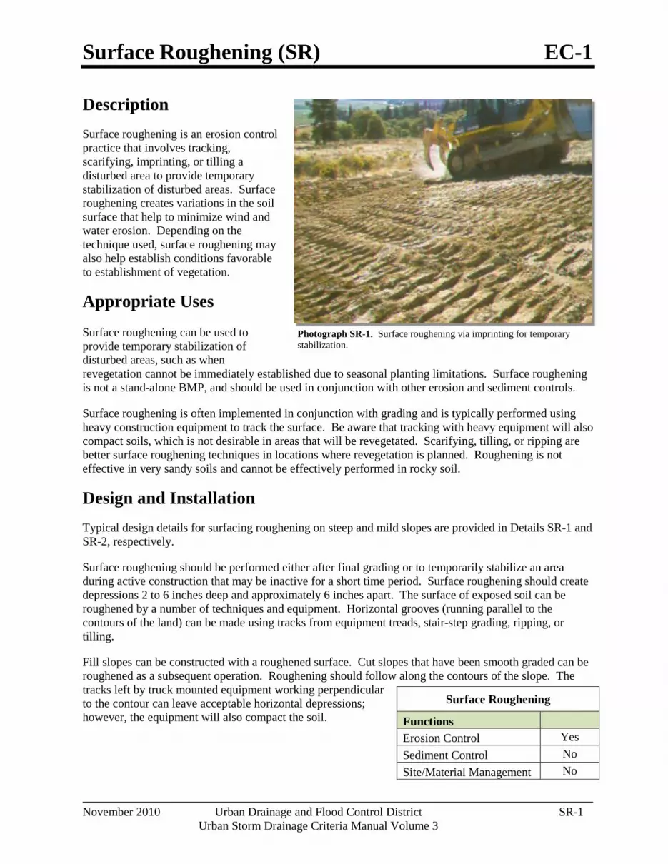
Surface Roughening (SR) EC-1
November 2010 Urban Drainage and Flood Control District SR-1 Urban Storm Drainage Criteria Manual Volume 3
Photograph SR-1. Surface roughening via imprinting for temporary stabilization.
Description Surface roughening is an erosion control practice that involves tracking, scarifying, imprinting, or tilling a disturbed area to provide temporary stabilization of disturbed areas. Surface roughening creates variations in the soil surface that help to minimize wind and water erosion. Depending on the technique used, surface roughening may also help establish conditions favorable to establishment of vegetation.
Appropriate Uses
Surface roughening can be used to provide temporary stabilization of disturbed areas, such as when revegetation cannot be immediately established due to seasonal planting limitations. Surface roughening is not a stand-alone BMP, and should be used in conjunction with other erosion and sediment controls.
Surface roughening is often implemented in conjunction with grading and is typically performed using heavy construction equipment to track the surface. Be aware that tracking with heavy equipment will also compact soils, which is not desirable in areas that will be revegetated. Scarifying, tilling, or ripping are better surface roughening techniques in locations where revegetation is planned. Roughening is not effective in very sandy soils and cannot be effectively performed in rocky soil.
Design and Installation Typical design details for surfacing roughening on steep and mild slopes are provided in Details SR-1 and SR-2, respectively.
Surface roughening should be performed either after final grading or to temporarily stabilize an area during active construction that may be inactive for a short time period. Surface roughening should create depressions 2 to 6 inches deep and approximately 6 inches apart. The surface of exposed soil can be roughened by a number of techniques and equipment. Horizontal grooves (running parallel to the contours of the land) can be made using tracks from equipment treads, stair-step grading, ripping, or tilling.
Fill slopes can be constructed with a roughened surface. Cut slopes that have been smooth graded can be roughened as a subsequent operation. Roughening should follow along the contours of the slope. The tracks left by truck mounted equipment working perpendicular to the contour can leave acceptable horizontal depressions; however, the equipment will also compact the soil.
Surface Roughening
Functions
Erosion Control Yes Sediment Control No Site/Material Management No

EC-1 Surface Roughening (SR)
SR-2 Urban Drainage and Flood Control District November 2010
Urban Storm Drainage Criteria Manual Volume 3
Maintenance and Removal Care should be taken not to drive vehicles or equipment over areas that have been surface roughened. Tire tracks will smooth the roughened surface and may cause runoff to collect into rills and gullies.
Because surface roughening is only a temporary control, additional treatments may be necessary to maintain the soil surface in a roughened condition.
Areas should be inspected for signs of erosion. Surface roughening is a temporary measure, and will not provide long-term erosion control.

Surface Roughening (SR) EC-1
November 2010 Urban Drainage and Flood Control District SR-3 Urban Storm Drainage Criteria Manual Volume 3

EC-1 Surface Roughening (SR)
SR-4 Urban Drainage and Flood Control District November 2010
Urban Storm Drainage Criteria Manual Volume 3

Temporary and Permanent Seeding (TS/PS) EC-2
June 2012 Urban Drainage and Flood Control District TS/PS-1 Urban Storm Drainage Criteria Manual Volume 3
Photograph TS/PS -1. Equipment used to drill seed. Photo courtesy of Douglas County.
Description Temporary seeding can be used to stabilize disturbed areas that will be inactive for an extended period. Permanent seeding should be used to stabilize areas at final grade that will not be otherwise stabilized. Effective seeding includes preparation of a seedbed, selection of an appropriate seed mixture, proper planting techniques, and protection of the seeded area with mulch, geotextiles, or other appropriate measures.
Appropriate Uses When the soil surface is disturbed and will remain inactive for an extended period (typically 30 days or longer), proactive stabilization measures should be implemented. If the inactive period is short-lived (on the order of two weeks), techniques such as surface roughening may be appropriate. For longer periods of inactivity, temporary seeding and mulching can provide effective erosion control. Permanent seeding should be used on finished areas that have not been otherwise stabilized.
Typically, local governments have their own seed mixes and timelines for seeding. Check jurisdictional requirements for seeding and temporary stabilization.
Design and Installation Effective seeding requires proper seedbed preparation, selection of an appropriate seed mixture, use of appropriate seeding equipment to ensure proper coverage and density, and protection with mulch or fabric until plants are established.
The USDCM Volume 2 Revegetation Chapter contains detailed seed mix, soil preparations, and seeding and mulching recommendations that may be referenced to supplement this Fact Sheet.
Drill seeding is the preferred seeding method. Hydroseeding is not recommended except in areas where steep slopes prevent use of drill seeding equipment, and even in these instances it is preferable to hand seed and mulch. Some jurisdictions do not allow hydroseeding or hydromulching.
Seedbed Preparation
Prior to seeding, ensure that areas to be revegetated have soil conditions capable of supporting vegetation. Overlot grading can result in loss of topsoil, resulting in poor quality subsoils at the ground surface that have low nutrient value, little organic matter content, few soil microorganisms, rooting restrictions, and conditions less conducive to infiltration of precipitation. As a result, it is typically necessary to provide stockpiled topsoil, compost, or other
Temporary and Permanent Seeding
Functions Erosion Control Yes Sediment Control No Site/Material Management No

EC-2 Temporary and Permanent Seeding (TS/PS)
TS/PS-2 Urban Drainage and Flood Control District June 2012
Urban Storm Drainage Criteria Manual Volume 3
soil amendments and rototill them into the soil to a depth of 6 inches or more.
Topsoil should be salvaged during grading operations for use and spread on areas to be revegetated later. Topsoil should be viewed as an important resource to be utilized for vegetation establishment, due to its water-holding capacity, structure, texture, organic matter content, biological activity, and nutrient content. The rooting depth of most native grasses in the semi-arid Denver metropolitan area is 6 to 18 inches. At a minimum, the upper 6 inches of topsoil should be stripped, stockpiled, and ultimately respread across areas that will be revegetated.
Where topsoil is not available, subsoils should be amended to provide an appropriate plant-growth medium. Organic matter, such as well digested compost, can be added to improve soil characteristics conducive to plant growth. Other treatments can be used to adjust soil pH conditions when needed. Soil testing, which is typically inexpensive, should be completed to determine and optimize the types and amounts of amendments that are required.
If the disturbed ground surface is compacted, rip or rototill the surface prior to placing topsoil. If adding compost to the existing soil surface, rototilling is necessary. Surface roughening will assist in placement of a stable topsoil layer on steeper slopes, and allow infiltration and root penetration to greater depth.
Prior to seeding, the soil surface should be rough and the seedbed should be firm, but neither too loose nor compacted. The upper layer of soil should be in a condition suitable for seeding at the proper depth and conducive to plant growth. Seed-to-soil contact is the key to good germination.
Seed Mix for Temporary Vegetation
To provide temporary vegetative cover on disturbed areas which will not be paved, built upon, or fully landscaped or worked for an extended period (typically 30 days or more), plant an annual grass appropriate for the time of planting and mulch the planted areas. Annual grasses suitable for the Denver metropolitan area are listed in Table TS/PS-1. These are to be considered only as general recommendations when specific design guidance for a particular site is not available. Local governments typically specify seed mixes appropriate for their jurisdiction.
Seed Mix for Permanent Revegetation
To provide vegetative cover on disturbed areas that have reached final grade, a perennial grass mix should be established. Permanent seeding should be performed promptly (typically within 14 days) after reaching final grade. Each site will have different characteristics and a landscape professional or the local jurisdiction should be contacted to determine the most suitable seed mix for a specific site. In lieu of a specific recommendation, one of the perennial grass mixes appropriate for site conditions and growth season listed in Table TS/PS-2 can be used. The pure live seed (PLS) rates of application recommended in these tables are considered to be absolute minimum rates for seed applied using proper drill-seeding equipment.
If desired for wildlife habitat or landscape diversity, shrubs such as rubber rabbitbrush (Chrysothamnus nauseosus), fourwing saltbush (Atriplex canescens) and skunkbrush sumac (Rhus trilobata) could be added to the upland seedmixes at 0.25, 0.5 and 1 pound PLS/acre, respectively. In riparian zones, planting root stock of such species as American plum (Prunus americana), woods rose (Rosa woodsii), plains cottonwood (Populus sargentii), and willow (Populus spp.) may be considered. On non-topsoiled upland sites, a legume such as Ladak alfalfa at 1 pound PLS/acre can be included as a source of nitrogen for perennial grasses.

Temporary and Permanent Seeding (TS/PS) EC-2
June 2012 Urban Drainage and Flood Control District TS/PS-3 Urban Storm Drainage Criteria Manual Volume 3
Seeding dates for the highest success probability of perennial species along the Front Range are generally in the spring from April through early May and in the fall after the first of September until the ground freezes. If the area is irrigated, seeding may occur in summer months, as well. See Table TS/PS-3 for appropriate seeding dates.
Table TS/PS-1. Minimum Drill Seeding Rates for Various Temporary Annual Grasses
Speciesa (Common name)
Growth Seasonb
Pounds of Pure Live Seed
(PLS)/acrec
Planting Depth
(inches) 1. Oats Cool 35 - 50 1 - 2 2. Spring wheat Cool 25 - 35 1 - 2 3. Spring barley Cool 25 - 35 1 - 2 4. Annual ryegrass Cool 10 - 15 ½ 5. Millet Warm 3 - 15 ½ - ¾ 6. Sudangrass Warm 5–10 ½ - ¾ 7. Sorghum Warm 5–10 ½ - ¾ 8. Winter wheat Cool 20–35 1 - 2 9. Winter barley Cool 20–35 1 - 2 10. Winter rye Cool 20–35 1 - 2 11. Triticale Cool 25–40 1 - 2
a Successful seeding of annual grass resulting in adequate plant growth will usually produce enough dead-plant residue to provide protection from wind and water erosion for an additional year. This assumes that the cover is not disturbed or mowed closer than 8 inches.
Hydraulic seeding may be substituted for drilling only where slopes are steeper than 3:1 or where access limitations exist. When hydraulic seeding is used, hydraulic mulching should be applied as a separate operation, when practical, to prevent the seeds from being encapsulated in the mulch.
b See Table TS/PS-3 for seeding dates. Irrigation, if consistently applied, may extend the use of cool season species during the summer months.
c Seeding rates should be doubled if seed is broadcast, or increased by 50 percent if done using a Brillion Drill or by hydraulic seeding.

EC-2 Temporary and Permanent Seeding (TS/PS)
TS/PS-4 Urban Drainage and Flood Control District June 2012
Urban Storm Drainage Criteria Manual Volume 3
Table TS/PS-2. Minimum Drill Seeding Rates for Perennial Grasses
Commona Name
Botanical Name
Growth Seasonb
Growth Form
Seeds/ Pound
Pounds of PLS/acre
Alakali Soil Seed Mix
Alkali sacaton Sporobolus airoides Cool Bunch 1,750,000 0.25
Basin wildrye Elymus cinereus Cool Bunch 165,000 2.5
Sodar streambank wheatgrass Agropyron riparium 'Sodar' Cool Sod 170,000 2.5 Jose tall wheatgrass Agropyron elongatum 'Jose' Cool Bunch 79,000 7.0
Arriba western wheatgrass Agropyron smithii 'Arriba' Cool Sod 110,000 5.5
Total 17.75 Fertile Loamy Soil Seed Mix
Ephriam crested wheatgrass Agropyron cristatum 'Ephriam' Cool Sod 175,000 2.0
Dural hard fescue Festuca ovina 'duriuscula' Cool Bunch 565,000 1.0
Lincoln smooth brome Bromus inermis leyss 'Lincoln' Cool Sod 130,000 3.0
Sodar streambank wheatgrass Agropyron riparium 'Sodar' Cool Sod 170,000 2.5
Arriba western wheatgrass Agropyron smithii 'Arriba' Cool Sod 110,000 7.0
Total 15.5 High Water Table Soil Seed Mix Meadow foxtail Alopecurus pratensis Cool Sod 900,000 0.5
Redtop Agrostis alba Warm Open sod 5,000,000 0.25
Reed canarygrass Phalaris arundinacea Cool Sod 68,000 0.5
Lincoln smooth brome Bromus inermis leyss 'Lincoln' Cool Sod 130,000 3.0
Pathfinder switchgrass Panicum virgatum 'Pathfinder' Warm Sod 389,000 1.0
Alkar tall wheatgrass Agropyron elongatum 'Alkar' Cool Bunch 79,000 5.5
Total 10.75 Transition Turf Seed Mixc Ruebens Canadian bluegrass Poa compressa 'Ruebens' Cool Sod 2,500,000 0.5
Dural hard fescue Festuca ovina 'duriuscula' Cool Bunch 565,000 1.0 Citation perennial ryegrass Lolium perenne 'Citation' Cool Sod 247,000 3.0
Lincoln smooth brome Bromus inermis leyss 'Lincoln' Cool Sod 130,000 3.0
Total 7.5

Temporary and Permanent Seeding (TS/PS) EC-2
June 2012 Urban Drainage and Flood Control District TS/PS-5 Urban Storm Drainage Criteria Manual Volume 3
Table TS/PS-2. Minimum Drill Seeding Rates for Perennial Grasses (cont.)
Common Name
Botanical Name
Growth Seasonb
Growth Form
Seeds/ Pound
Pounds of PLS/acre
Sandy Soil Seed Mix
Blue grama Bouteloua gracilis Warm Sod-forming bunchgrass 825,000 0.5
Camper little bluestem Schizachyrium scoparium 'Camper' Warm Bunch 240,000 1.0
Prairie sandreed Calamovilfa longifolia Warm Open sod 274,000 1.0
Sand dropseed Sporobolus cryptandrus Cool Bunch 5,298,000 0.25
Vaughn sideoats grama Bouteloua curtipendula 'Vaughn' Warm Sod 191,000 2.0
Arriba western wheatgrass Agropyron smithii 'Arriba' Cool Sod 110,000 5.5
Total 10.25 Heavy Clay, Rocky Foothill Seed Mix
Ephriam crested wheatgrassd Agropyron cristatum 'Ephriam' Cool Sod 175,000 1.5
Oahe Intermediate wheatgrass Agropyron intermedium 'Oahe' Cool Sod 115,000 5.5
Vaughn sideoats gramae Bouteloua curtipendula 'Vaughn' Warm Sod 191,000 2.0
Lincoln smooth brome Bromus inermis leyss 'Lincoln' Cool Sod 130,000 3.0
Arriba western wheatgrass Agropyron smithii 'Arriba' Cool Sod 110,000 5.5
Total 17.5 a All of the above seeding mixes and rates are based on drill seeding followed by crimped straw mulch. These rates should be
doubled if seed is broadcast and should be increased by 50 percent if the seeding is done using a Brillion Drill or is applied through hydraulic seeding. Hydraulic seeding may be substituted for drilling only where slopes are steeper than 3:1. If hydraulic seeding is used, hydraulic mulching should be done as a separate operation.
b See Table TS/PS-3 for seeding dates. c If site is to be irrigated, the transition turf seed rates should be doubled. d Crested wheatgrass should not be used on slopes steeper than 6H to 1V. e Can substitute 0.5 lbs PLS of blue grama for the 2.0 lbs PLS of Vaughn sideoats grama.

EC-2 Temporary and Permanent Seeding (TS/PS)
TS/PS-6 Urban Drainage and Flood Control District June 2012
Urban Storm Drainage Criteria Manual Volume 3
Table TS/PS-3. Seeding Dates for Annual and Perennial Grasses
Annual Grasses (Numbers in table reference
species in Table TS/PS-1)
Perennial Grasses
Seeding Dates Warm Cool Warm Cool January 1–March 15 March 16–April 30 4 1,2,3 May 1–May 15 4 May 16–June 30 4,5,6,7 July 1–July 15 5,6,7 July 16–August 31 September 1–September 30 8,9,10,11 October 1–December 31
Mulch
Cover seeded areas with mulch or an appropriate rolled erosion control product to promote establishment of vegetation. Anchor mulch by crimping, netting or use of a non-toxic tackifier. See the Mulching BMP Fact Sheet for additional guidance.
Maintenance and Removal Monitor and observe seeded areas to identify areas of poor growth or areas that fail to germinate. Reseed and mulch these areas, as needed.
An area that has been permanently seeded should have a good stand of vegetation within one growing season if irrigated and within three growing seasons without irrigation in Colorado. Reseed portions of the site that fail to germinate or remain bare after the first growing season.
Seeded areas may require irrigation, particularly during extended dry periods. Targeted weed control may also be necessary.
Protect seeded areas from construction equipment and vehicle access.

Soil Binders (SB) EC-3
November 2010 Urban Drainage and Flood Control District SB-1 Urban Storm Drainage Criteria Manual Volume 3
Description Soil binders include a broad range of treatments that can be applied to exposed soils for temporary stabilization to reduce wind and water erosion. Soil binders may be applied alone or as tackifiers in conjunction with mulching and seeding applications.
Acknowledgement: This BMP Fact Sheet has been adapted from the 2003 California Stormwater Quality Association (CASQA) Stormwater BMP Handbook: Construction (www.cabmphandbooks.com).
Appropriate Uses Soil binders can be used for short-term, temporary stabilization of soils on both mild and steep slopes. Soil binders are often used in areas where work has temporarily stopped, but is expected to resume before revegetation can become established. Binders are also useful on stockpiled soils or where temporary or permanent seeding has occurred.
Prior to selecting a soil binder, check with the state and local jurisdiction to ensure that the chemicals used in the soil binders are allowed. The water quality impacts of some types of soil binders are relatively unknown and may not be allowed due to concerns about potential environmental impacts. Soil binders must be environmentally benign (non-toxic to plant and animal life), easy to apply, easy to maintain, economical, and should not stain paved or painted surfaces.
Soil binders should not be used in vehicle or pedestrian high traffic areas, due to loss in effectiveness under these conditions.
Site soil type will dictate appropriate soil binders to be used. Be aware that soil binders may not function effectively on silt or clay soils or highly compacted areas. Check manufacturer's recommendations for appropriateness with regard to soil conditions. Some binders may not be suitable for areas with existing vegetation.
Design and Installation Properties of common soil binders used for erosion control are provided in Table SB-1. Design and installation guidance below are provided for general reference. Follow the manufacturer's instructions for application rates and procedures.
Soil Binders
Functions
Erosion Control Yes Sediment Control No Site/Material Management Moderate
Photograph SB-1. Tackifier being applied to provide temporary soil stabilization. Photo courtesy of Douglas County.

EC-3 Soil Binders (SB)
SB-2 Urban Drainage and Flood Control District November 2010
Urban Storm Drainage Criteria Manual Volume 3
Table SB-1. Properties of Soil Binders for Erosion Control (Source: CASQA 2003)
Evaluation Criteria
Binder Type
Plant Material Based
(short lived)
Plant Material Based
(long lived)
Polymeric Emulsion Blends
Cementitious-Based Binders
Resistance to Leaching High High Low to Moderate Moderate
Resistance to Abrasion Moderate Low Moderate to High Moderate to High
Longevity Short to Medium Medium Medium to Long Medium
Minimum Curing Time before Rain 9 to 18 hours 19 to 24 hours 0 to 24 hours 4 to 8 hours
Compatibility with Existing Vegetation Good Poor Poor Poor
Mode of Degradation Biodegradable Biodegradable Photodegradable/
Chemically Degradable
Photodegradable/ Chemically Degradable
Specialized Application Equipment
Water Truck or Hydraulic Mulcher
Water Truck or Hydraulic Mulcher
Water Truck or Hydraulic Mulcher
Water Truck or Hydraulic Mulcher
Liquid/Powder Powder Liquid Liquid/Powder Powder
Surface Crusting Yes, but
dissolves on rewetting
Yes Yes, but dissolves on rewetting Yes
Clean Up Water Water Water Water
Erosion Control Application Rate Varies Varies Varies 4,000 to 12,000
lbs/acre Typ.

Soil Binders (SB) EC-3
November 2010 Urban Drainage and Flood Control District SB-3 Urban Storm Drainage Criteria Manual Volume 3
Factors to consider when selecting a soil binder generally include:
Suitability to situation: Consider where the soil binder will be applied, if it needs a high resistance to leaching or abrasion, and whether it needs to be compatible with existing vegetation. Determine the length of time soil stabilization will be needed, and if the soil binder will be placed in an area where it will degrade rapidly. In general, slope steepness is not a discriminating factor.
Soil types and surface materials: Fines and moisture content are key properties of surface materials. Consider a soil binder's ability to penetrate, likelihood of leaching, and ability to form a surface crust on the surface materials.
Frequency of application: The frequency of application can be affected by subgrade conditions, surface type, climate, and maintenance schedule. Frequent applications could lead to high costs. Application frequency may be minimized if the soil binder has good penetration, low evaporation, and good longevity. Consider also that frequent application will require frequent equipment clean up.
An overview of major categories of soil binders, corresponding to the types included in Table SB-1 follows.
Plant-Material Based (Short Lived) Binders
Guar: A non-toxic, biodegradable, natural galactomannan-based hydrocolloid treated with dispersant agents for easy field mixing. It should be mixed with water at the rate of 11 to 15 lbs per 1,000 gallons. Recommended minimum application rates are provided in Table SB-2.
Table SB-2. Application Rates for Guar Soil Stabilizer
Slope (H:V) Flat 4:1 3:1 2:1 1:1
Application Rate (lb/acre) 40 45 50 60 70
Psyllium: Composed of the finely ground muciloid coating of plantago seeds that is applied as a wet slurry to the surface of the soil. It dries to form a firm but rewettable membrane that binds soil particles together but permits germination and growth of seed. Psyllium requires 12 to 18 hours drying time. Application rates should be from 80 to 200 lbs/acre, with enough water in solution to allow for a uniform slurry flow.
Starch: Non-ionic, cold-water soluble (pre-gelatinized) granular cornstarch. The material is mixed with water and applied at the rate of 150 lb/acre. Approximate drying time is 9 to 12 hours.
Plant-Material Based (Long Lived) Binders
Pitch and Rosin Emulsion: Generally, a non-ionic pitch and rosin emulsion has a minimum solids content of 48 percent. The rosin should be a minimum of 26 percent of the total solids content. The soil stabilizer should be a non-corrosive, water dilutable emulsion that upon application cures to a water insoluble binding and cementing agent. For soil erosion control applications, the emulsion is diluted and should be applied as follows:
o For clayey soil: 5 parts water to 1 part emulsion
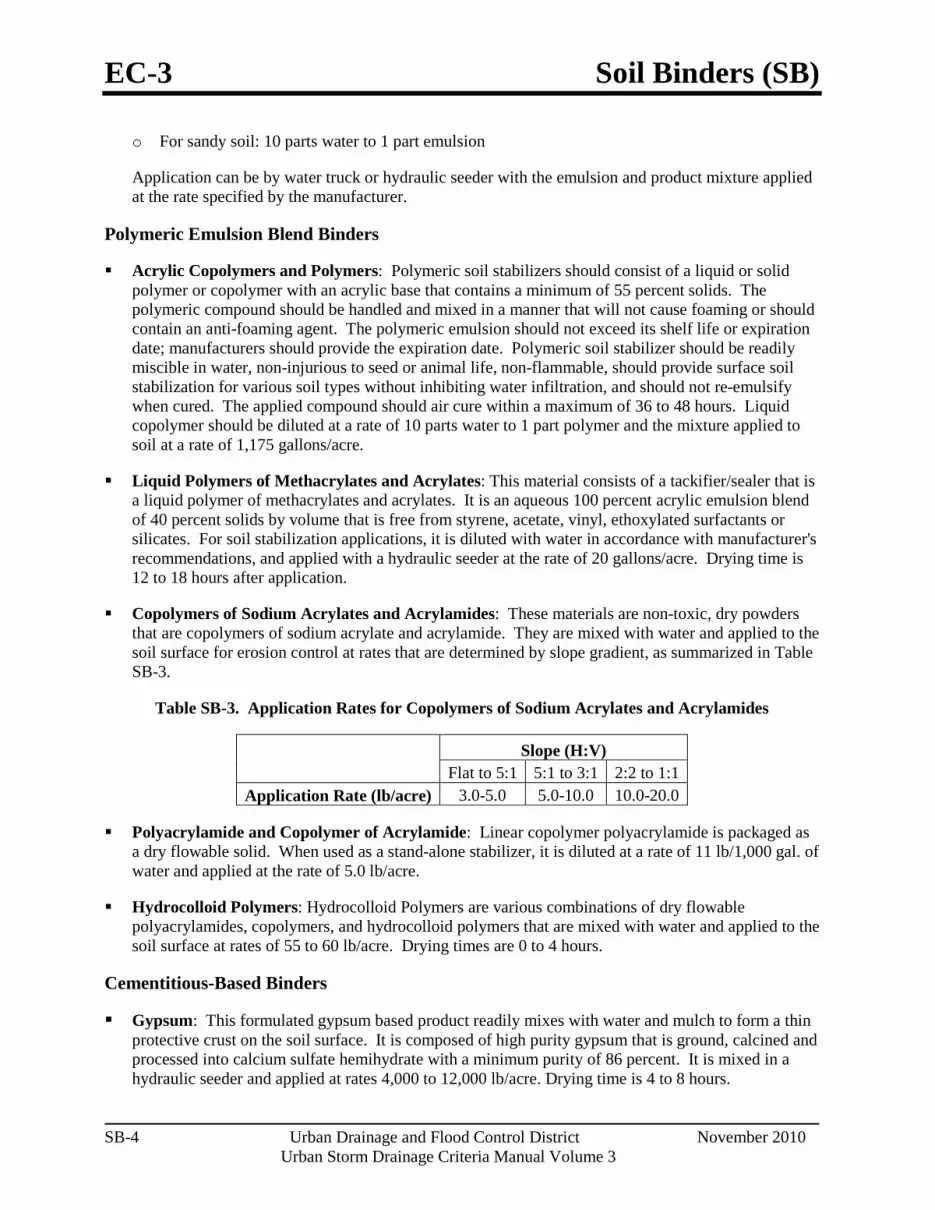
EC-3 Soil Binders (SB)
SB-4 Urban Drainage and Flood Control District November 2010
Urban Storm Drainage Criteria Manual Volume 3
o For sandy soil: 10 parts water to 1 part emulsion
Application can be by water truck or hydraulic seeder with the emulsion and product mixture applied at the rate specified by the manufacturer.
Polymeric Emulsion Blend Binders
Acrylic Copolymers and Polymers: Polymeric soil stabilizers should consist of a liquid or solid polymer or copolymer with an acrylic base that contains a minimum of 55 percent solids. The polymeric compound should be handled and mixed in a manner that will not cause foaming or should contain an anti-foaming agent. The polymeric emulsion should not exceed its shelf life or expiration date; manufacturers should provide the expiration date. Polymeric soil stabilizer should be readily miscible in water, non-injurious to seed or animal life, non-flammable, should provide surface soil stabilization for various soil types without inhibiting water infiltration, and should not re-emulsify when cured. The applied compound should air cure within a maximum of 36 to 48 hours. Liquid copolymer should be diluted at a rate of 10 parts water to 1 part polymer and the mixture applied to soil at a rate of 1,175 gallons/acre.
Liquid Polymers of Methacrylates and Acrylates: This material consists of a tackifier/sealer that is a liquid polymer of methacrylates and acrylates. It is an aqueous 100 percent acrylic emulsion blend of 40 percent solids by volume that is free from styrene, acetate, vinyl, ethoxylated surfactants or silicates. For soil stabilization applications, it is diluted with water in accordance with manufacturer's recommendations, and applied with a hydraulic seeder at the rate of 20 gallons/acre. Drying time is 12 to 18 hours after application.
Copolymers of Sodium Acrylates and Acrylamides: These materials are non-toxic, dry powders that are copolymers of sodium acrylate and acrylamide. They are mixed with water and applied to the soil surface for erosion control at rates that are determined by slope gradient, as summarized in Table SB-3.
Table SB-3. Application Rates for Copolymers of Sodium Acrylates and Acrylamides
Slope (H:V) Flat to 5:1 5:1 to 3:1 2:2 to 1:1
Application Rate (lb/acre) 3.0-5.0 5.0-10.0 10.0-20.0
Polyacrylamide and Copolymer of Acrylamide: Linear copolymer polyacrylamide is packaged as a dry flowable solid. When used as a stand-alone stabilizer, it is diluted at a rate of 11 lb/1,000 gal. of water and applied at the rate of 5.0 lb/acre.
Hydrocolloid Polymers: Hydrocolloid Polymers are various combinations of dry flowable polyacrylamides, copolymers, and hydrocolloid polymers that are mixed with water and applied to the soil surface at rates of 55 to 60 lb/acre. Drying times are 0 to 4 hours.
Cementitious-Based Binders
Gypsum: This formulated gypsum based product readily mixes with water and mulch to form a thin protective crust on the soil surface. It is composed of high purity gypsum that is ground, calcined and processed into calcium sulfate hemihydrate with a minimum purity of 86 percent. It is mixed in a hydraulic seeder and applied at rates 4,000 to 12,000 lb/acre. Drying time is 4 to 8 hours.

Soil Binders (SB) EC-3
November 2010 Urban Drainage and Flood Control District SB-5 Urban Storm Drainage Criteria Manual Volume 3
Installation
After selecting an appropriate soil binder, the untreated soil surface must be prepared before applying the soil binder. The untreated soil surface must contain sufficient moisture to assist the agent in achieving uniform distribution. In general, the following steps should be followed:
Follow manufacturer's written recommendations for application rates, pre-wetting of application area, and cleaning of equipment after use.
Prior to application, roughen embankment and fill areas.
Consider the drying time for the selected soil binder and apply with sufficient time before anticipated rainfall. Soil binders should not be applied during or immediately before rainfall.
Avoid over spray onto roads, sidewalks, drainage channels, sound walls, existing vegetation, etc.
Soil binders should not be applied to frozen soil, areas with standing water, under freezing or rainy conditions, or when the temperature is below 40°F during the curing period.
More than one treatment is often necessary, although the second treatment may be diluted or have a lower application rate.
Generally, soil binders require a minimum curing time of 24 hours before they are fully effective. Refer to manufacturer's instructions for specific cure time.
For liquid agents:
o Crown or slope ground to avoid ponding.
o Uniformly pre-wet ground at 0.03 to 0.3 gal/yd2 or according to manufacturer's recommendations.
o Apply solution under pressure. Overlap solution 6 to 12 in.
o Allow treated area to cure for the time recommended by the manufacturer, typically at least 24 hours.
o Apply second treatment before first treatment becomes ineffective, using 50 percent application rate.
o In low humidity, reactivate chemicals by re-wetting with water at 0.1 to 0.2 gal/yd2.
Maintenance and Removal Soil binders tend to break down due to natural weathering. Weathering rates depend on a variety of site-specific and product characteristics. Consult the manufacturer for recommended reapplication rates and reapply the selected soil binder as needed to maintain effectiveness.
Soil binders can fail after heavy rainfall events and may require reapplication. In particular, soil binders will generally experience spot failures during heavy rainfall events. If runoff penetrates the soil at the top of a slope treated with a soil binder, it is likely that the runoff will undercut the stabilized soil layer and discharge at a point further down slope.

EC-3 Soil Binders (SB)
SB-6 Urban Drainage and Flood Control District November 2010
Urban Storm Drainage Criteria Manual Volume 3
Areas where erosion is evident should be repaired and soil binder or other stabilization reapplied, as needed. Care should be exercised to minimize the damage to protected areas while making repairs.
Most binders biodegrade after exposure to sun, oxidation, heat and biological organisms; therefore, removal of the soil binder is not typically required.

Mulching (MU) EC-4
June 2012 Urban Drainage and Flood Control District MU-1 Urban Storm Drainage Criteria Manual Volume 3
Photograph MU-1. An area that was recently seeded, mulched, and crimped.
Description Mulching consists of evenly applying straw, hay, shredded wood mulch, rock, bark or compost to disturbed soils and securing the mulch by crimping, tackifiers, netting or other measures. Mulching helps reduce erosion by protecting bare soil from rainfall impact, increasing infiltration, and reducing runoff. Although often applied in conjunction with temporary or permanent seeding, it can also be used for temporary stabilization of areas that cannot be reseeded due to seasonal constraints.
Mulch can be applied either using standard mechanical dry application methods or using hydromulching equipment that hydraulically applies a slurry of water, wood fiber mulch, and often a tackifier.
Appropriate Uses Use mulch in conjunction with seeding to help protect the seedbed and stabilize the soil. Mulch can also be used as a temporary cover on low to mild slopes to help temporarily stabilize disturbed areas where growing season constraints prevent effective reseeding. Disturbed areas should be properly mulched and tacked, or seeded, mulched and tacked promptly after final grade is reached (typically within no longer than 14 days) on portions of the site not otherwise permanently stabilized.
Standard dry mulching is encouraged in most jurisdictions; however, hydromulching may not be allowed in certain jurisdictions or may not be allowed near waterways.
Do not apply mulch during windy conditions.
Design and Installation Prior to mulching, surface-roughen areas by rolling with a crimping or punching type roller or by track walking. Track walking should only be used where other methods are impractical because track walking with heavy equipment typically compacts the soil.
A variety of mulches can be used effectively at construction sites. Consider the following:
Mulch
Functions Erosion Control Yes
Sediment Control Moderate Site/Material Management No

EC-4 Mulching (MU)
MU-2 Urban Drainage and Flood Control District June 2012
Urban Storm Drainage Criteria Manual Volume 3
Clean, weed-free and seed-free cereal grain straw should be applied evenly at a rate of 2 tons per acre and must be tacked or fastened by a method suitable for the condition of the site. Straw mulch must be anchored (and not merely placed) on the surface. This can be accomplished mechanically by crimping or with the aid of tackifiers or nets. Anchoring with a crimping implement is preferred, and is the recommended method for areas flatter than 3:1. Mechanical crimpers must be capable of tucking the long mulch fibers into the soil to a depth of 3 inches without cutting them. An agricultural disk, while not an ideal substitute, may work if the disk blades are dull or blunted and set vertically; however, the frame may have to be weighted to afford proper soil penetration.
Grass hay may be used in place of straw; however, because hay is comprised of the entire plant including seed, mulching with hay may seed the site with non-native grass species which might in turn out-compete the native seed. Alternatively, native species of grass hay may be purchased, but can be difficult to find and are more expensive than straw. Purchasing and utilizing a certified weed-free straw is an easier and less costly mulching method. When using grass hay, follow the same guidelines as for straw (provided above).
On small areas sheltered from the wind and heavy runoff, spraying a tackifier on the mulch is satisfactory for holding it in place. For steep slopes and special situations where greater control is needed, erosion control blankets anchored with stakes should be used instead of mulch.
Hydraulic mulching consists of wood cellulose fibers mixed with water and a tackifying agent and should be applied at a rate of no less than 1,500 pounds per acre (1,425 lbs of fibers mixed with at least 75 lbs of tackifier) with a hydraulic mulcher. For steeper slopes, up to 2000 pounds per acre may be required for effective hydroseeding. Hydromulch typically requires up to 24 hours to dry; therefore, it should not be applied immediately prior to inclement weather. Application to roads, waterways and existing vegetation should be avoided.
Erosion control mats, blankets, or nets are recommended to help stabilize steep slopes (generally 3:1 and steeper) and waterways. Depending on the product, these may be used alone or in conjunction with grass or straw mulch. Normally, use of these products will be restricted to relatively small areas. Biodegradable mats made of straw and jute, straw-coconut, coconut fiber, or excelsior can be used instead of mulch. (See the ECM/TRM BMP for more information.)
Some tackifiers or binders may be used to anchor mulch. Check with the local jurisdiction for allowed tackifiers. Manufacturer's recommendations should be followed at all times. (See the Soil Binder BMP for more information on general types of tackifiers.)
Rock can also be used as mulch. It provides protection of exposed soils to wind and water erosion and allows infiltration of precipitation. An aggregate base course can be spread on disturbed areas for temporary or permanent stabilization. The rock mulch layer should be thick enough to provide full coverage of exposed soil on the area it is applied.
Maintenance and Removal After mulching, the bare ground surface should not be more than 10 percent exposed. Reapply mulch, as needed, to cover bare areas.

Compost Blanket and Filter Berm (CB) EC-5
November 2010 Urban Drainage and Flood Control District CB-1 Urban Storm Drainage Criteria Manual Volume 3
Photograph CB-1. Application of a compost blanket to a disturbed area. Photo courtesy of Caltrans.
Description A compost blanket is a layer of compost uniformly applied to the soil in disturbed areas to control erosion, facilitate revegetation, and retain sediment resulting from sheet-flow runoff.
A compost filter berm is a dike of compost or a compost product that is placed perpendicular to runoff to control erosion in disturbed areas and retain sediment. Compost berms can be placed at regular intervals to help reduce the formation of rill and gully erosion when a compost blanket is stabilizing a slope.
Appropriate Uses Compost blankets can be used as an alternative to erosion control blankets and mulching to help stabilize disturbed areas where sheet flow conditions are present. Compost blankets should not be used in areas of concentrated flows. Compost provides an excellent source of nutrients for plant growth, and should be considered for use in areas that will be permanently vegetated.
Design and Installation See Detail CB-1 for design details and notes.
Do not place compost in areas where it can easily be transported into drainage pathways or waterways. When using a compost blanket on a slope, berms should be installed periodically to reduce the potential for concentrated flow and rilling. Seeding should be completed before an area is composted or incorporated into the compost.
Compost quality is an important consideration when selecting compost blankets or berms. Representative compost quality factors include pH, salinity, moisture content, organic matter content, stability (maturity), and physical contaminants. The compost should meet all local, state, and federal quality requirements. Biosolids compost must meet the Standards for Class A biosolids outlined in 40 CFR Part 503. The U.S. Composting Council (USCC) certifies compost products under its Seal of Testing Assurance (STA) Program. Compost producers whose products have been certified through the STA Program provide customers with a standard product label that allows comparison between compost products. Only STA certified, Class I compost should be used.
Compost Blankets and Berms
Functions Erosion Control Yes Sediment Control Moderate Site/Material Management No
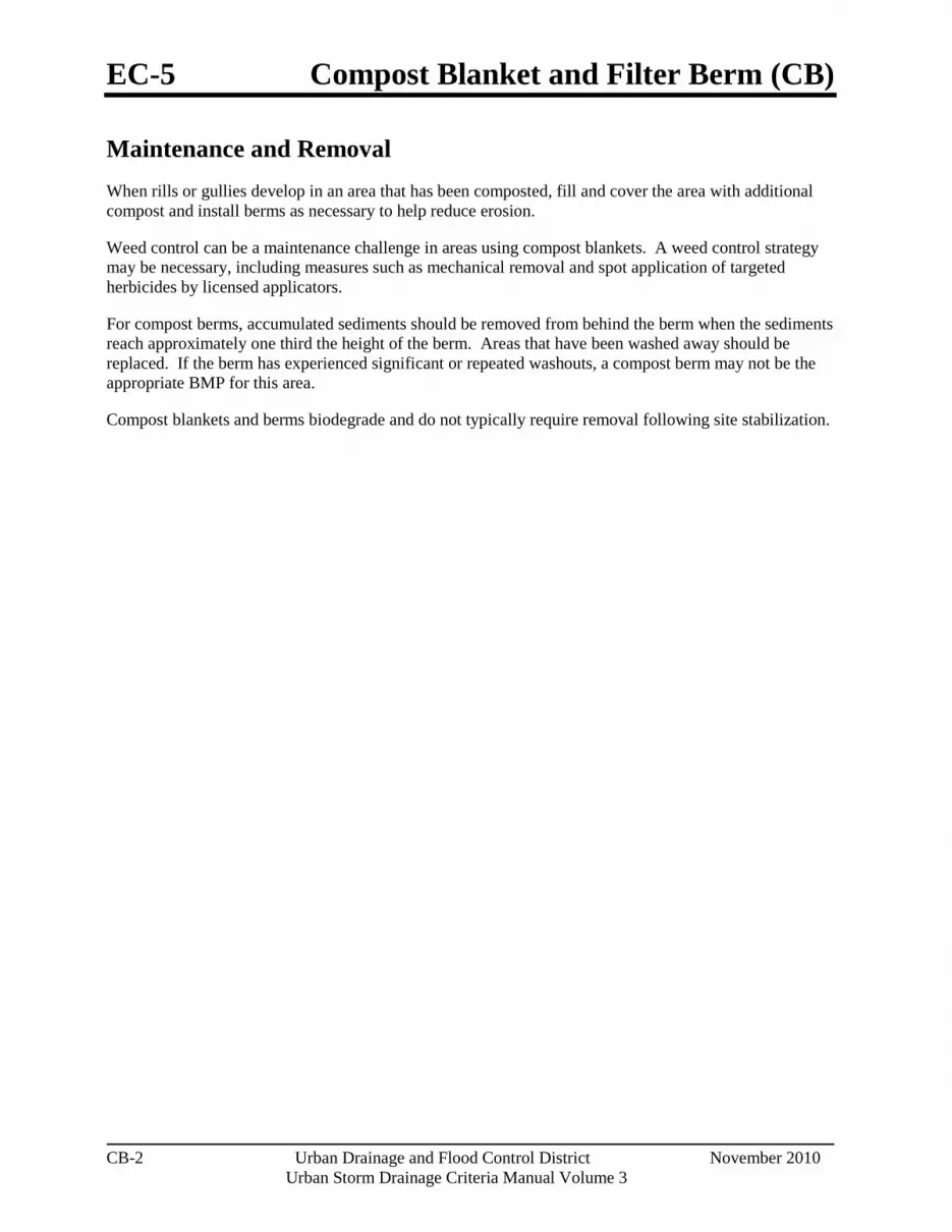
EC-5 Compost Blanket and Filter Berm (CB)
CB-2 Urban Drainage and Flood Control District November 2010
Urban Storm Drainage Criteria Manual Volume 3
Maintenance and Removal When rills or gullies develop in an area that has been composted, fill and cover the area with additional compost and install berms as necessary to help reduce erosion.
Weed control can be a maintenance challenge in areas using compost blankets. A weed control strategy may be necessary, including measures such as mechanical removal and spot application of targeted herbicides by licensed applicators.
For compost berms, accumulated sediments should be removed from behind the berm when the sediments reach approximately one third the height of the berm. Areas that have been washed away should be replaced. If the berm has experienced significant or repeated washouts, a compost berm may not be the appropriate BMP for this area.
Compost blankets and berms biodegrade and do not typically require removal following site stabilization.
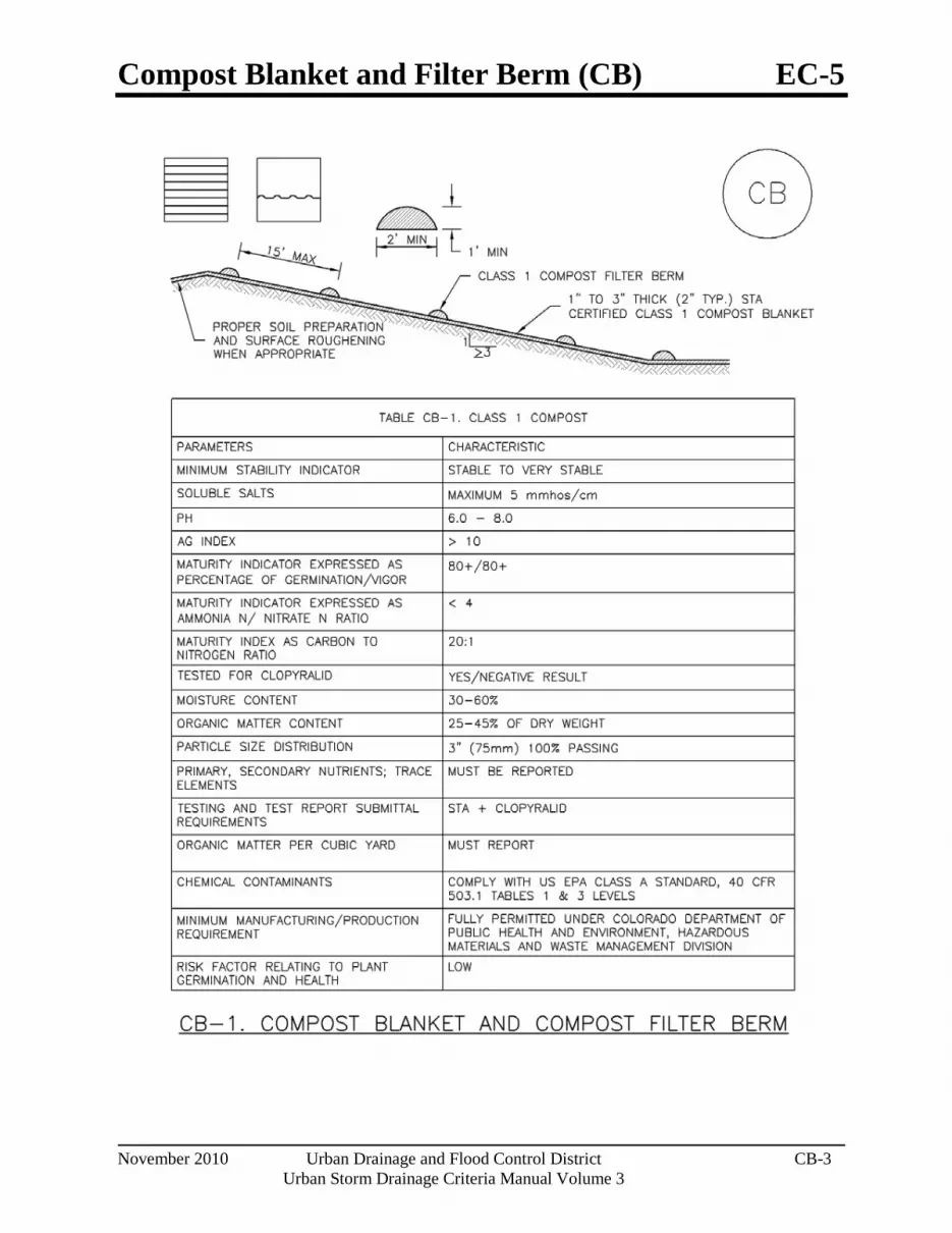
Compost Blanket and Filter Berm (CB) EC-5
November 2010 Urban Drainage and Flood Control District CB-3 Urban Storm Drainage Criteria Manual Volume 3

EC-5 Compost Blanket and Filter Berm (CB)
CB-4 Urban Drainage and Flood Control District November 2010
Urban Storm Drainage Criteria Manual Volume 3

Rolled Erosion Control Products (RECP) EC-6
November 2010 Urban Drainage and Flood Control District RECP-1 Urban Storm Drainage Criteria Manual Volume 3
Photograph RECP-1. Erosion control blanket protecting the slope from erosion and providing favorable conditions for revegetation.
Description Rolled Erosion Control Products (RECPs) include a variety of temporary or permanently installed manufactured products designed to control erosion and enhance vegetation establishment and survivability, particularly on slopes and in channels. For applications where natural vegetation alone will provide sufficient permanent erosion protection, temporary products such as netting, open weave textiles and a variety of erosion control blankets (ECBs) made of biodegradable natural materials (e.g., straw, coconut fiber) can be used. For applications where natural vegetation alone will not be sustainable under expected flow conditions, permanent rolled erosion control products such as turf reinforcement mats (TRMs) can be used. In particular, turf reinforcement mats are designed for discharges that exert velocities and sheer stresses that exceed the typical limits of mature natural vegetation.
Appropriate Uses RECPs can be used to control erosion in conjunction with revegetation efforts, providing seedbed protection from wind and water erosion. These products are often used on disturbed areas on steep slopes, in areas with highly erosive soils, or as part of drainageway stabilization. In order to select the appropriate RECP for site conditions, it is important to have a general understanding of the general types of these products, their expected longevity, and general characteristics.
The Erosion Control Technology Council (ECTC 2005) characterizes rolled erosion control products according to these categories:
Mulch control netting: A planar woven natural fiber or extruded geosynthetic mesh used as a temporary degradable rolled erosion control product to anchor loose fiber mulches.
Open weave textile: A temporary degradable rolled erosion control product composed of processed natural or polymer yarns woven into a matrix, used to provide erosion control and facilitate vegetation establishment.
Erosion control blanket (ECB): A temporary degradable rolled erosion control product composed of processed natural or polymer fibers which are mechanically, structurally or chemically bound together to form a continuous matrix to provide erosion control and facilitate vegetation establishment. ECBs can be further differentiated into rapidly degrading single-net and double-net types or slowly degrading types.
Rolled Erosion Control Products
Functions Erosion Control Yes Sediment Control No Site/Material Management No

EC-6 Rolled Erosion Control Products (RECP)
RECP-2 Urban Drainage and Flood Control District November 2010
Urban Storm Drainage Criteria Manual Volume 3
Turf Reinforcement Mat (TRM): A rolled erosion control product composed of non-degradable synthetic fibers, filaments, nets, wire mesh, and/or other elements, processed into a permanent, three-dimensional matrix of sufficient thickness. TRMs, which may be supplemented with degradable components, are designed to impart immediate erosion protection, enhance vegetation establishment and provide long-term functionality by permanently reinforcing vegetation during and after maturation. Note: TRMs are typically used in hydraulic applications, such as high flow ditches and channels, steep slopes, stream banks, and shorelines, where erosive forces may exceed the limits of natural, unreinforced vegetation or in areas where limited vegetation establishment is anticipated.
Tables RECP-1 and RECP-2 provide guidelines for selecting rolled erosion control products appropriate to site conditions and desired longevity. Table RECP-1 is for conditions where natural vegetation alone will provide permanent erosion control, whereas Table RECP-2 is for conditions where vegetation alone will not be adequately stable to provide long-term erosion protection due to flow or other conditions.

Rolled Erosion Control Products (RECP) EC-6
November 2010 Urban Drainage and Flood Control District RECP-3 Urban Storm Drainage Criteria Manual Volume 3
Table RECP-1. ECTC Standard Specification for Temporary Rolled Erosion Control Products (Adapted from Erosion Control Technology Council 2005)
Product Description Slope Applications*
Channel Applications*
Minimum Tensile
Strength1
Expected Longevity
Maximum Gradient C Factor2,5 Max. Shear
Stress3,4,6
Mulch Control Nets 5:1 (H:V) ≤0.10 @ 5:1
0.25 lbs/ft2 (12 Pa)
5 lbs/ft (0.073 kN/m)
Up to 12 months
Netless Rolled Erosion Control Blankets
4:1 (H:V) ≤0.10 @ 4:1
0.5 lbs/ft2 (24 Pa)
5 lbs/ft (0.073 kN/m)
Single-net Erosion Control Blankets & Open Weave Textiles
3:1 (H:V) ≤0.15 @ 3:1
1.5 lbs/ft2 (72 Pa)
50 lbs/ft (0.73 kN/m)
Double-net Erosion Control Blankets 2:1 (H:V) ≤0.20 @
2:1 1.75 lbs/ft2
(84 Pa) 75 lbs/ft
(1.09 kN/m)
Mulch Control Nets 5:1 (H:V) ≤0.10 @ 5:1
0.25 lbs/ft2 (12 Pa)
25 lbs/ft (0.36 kN/m) 24 months
Erosion Control Blankets & Open Weave Textiles (slowly degrading)
1.5:1 (H:V) ≤0.25 @ 1.5:1
2.00 lbs/ft2 (96 Pa)
100 lbs/ft (1.45 kN/m) 24 months
Erosion Control Blankets & Open Weave Textiles
1:1 (H:V) ≤0.25 @ 1:1
2.25 lbs/ft2 (108 Pa)
125 lbs/ft (1.82 kN/m) 36 months
* C Factor and shear stress for mulch control nettings must be obtained with netting used in conjunction with pre-applied mulch material. (See Section 5.3 of Chapter 7 Construction BMPs for more information on the C Factor.) 1 Minimum Average Roll Values, Machine direction using ECTC Mod. ASTM D 5035. 2 C Factor calculated as ratio of soil loss from RECP protected slope (tested at specified or greater gradient, H:V) to ratio of soil loss from unprotected (control) plot in large-scale testing. 3 Required minimum shear stress RECP (unvegetated) can sustain without physical damage or excess erosion (> 12.7 mm (0.5 in) soil loss) during a 30-minute flow event in large-scale testing. 4 The permissible shear stress levels established for each performance category are based on historical experience with products characterized by Manning's roughness coefficients in the range of 0.01 - 0.05. 5 Acceptable large-scale test methods may include ASTM D 6459, or other independent testing deemed acceptable by the engineer. 6 Per the engineer’s discretion. Recommended acceptable large-scale testing protocol may include ASTM D 6460, or other independent testing deemed acceptable by the engineer.

EC-6 Rolled Erosion Control Products (RECP)
RECP-4 Urban Drainage and Flood Control District November 2010
Urban Storm Drainage Criteria Manual Volume 3
Table RECP-2. ECTC Standard Specification for Permanent1 Rolled Erosion Control Products (Adapted from: Erosion Control Technology Council 2005)
Product Type Slope Applications Channel Applications
TRMs with a minimum thickness of 0.25 inches (6.35 mm) per ASTM D 6525 and UV stability of 80% per ASTM D 4355 (500 hours exposure).
Maximum Gradient
Maximum Shear Stress4,5
Minimum Tensile
Strength2,3
0.5:1 (H:V) 6.0 lbs/ft2 (288 Pa) 125 lbs/ft (1.82 kN/m)
0.5:1 (H:V) 8.0 lbs/ft2 (384 Pa) 150 lbs/ft (2.19 kN/m)
0.5:1 (H:V) 10.0 lbs/ft2 (480 Pa) 175 lbs/ft (2.55 kN/m)
1 For TRMs containing degradable components, all property values must be obtained on the non-degradable portion of the matting alone. 2 Minimum Average Roll Values, machine direction only for tensile strength determination using ASTM D 6818 (Supersedes Mod. ASTM D 5035 for RECPs) 3 Field conditions with high loading and/or high survivability requirements may warrant the use of a TRM with a tensile strength of 44 kN/m (3,000 lb/ft) or greater. 4 Required minimum shear stress TRM (fully vegetated) can sustain without physical damage or excess erosion (> 12.7 mm (0.5 in.) soil loss) during a 30-minute flow event in large scale testing. 5 Acceptable large-scale testing protocols may include ASTM D 6460, or other independent testing deemed acceptable by the engineer.
Design and Installation RECPs should be installed according to manufacturer’s specifications and guidelines. Regardless of the type of product used, it is important to ensure no gaps or voids exist under the material and that all corners of the material are secured using stakes and trenching. Continuous contact between the product and the soil is necessary to avoid failure. Never use metal stakes to secure temporary erosion control products. Often wooden stakes are used to anchor RECPs; however, wood stakes may present installation and maintenance challenges and generally take a long time to biodegrade. Some local jurisdictions have had favorable experiences using biodegradable stakes.
This BMP Fact Sheet provides design details for several commonly used ECB applications, including:
ECB-1 Pipe Outlet to Drainageway
ECB-2 Small Ditch or Drainageway
ECB-3 Outside of Drainageway

Rolled Erosion Control Products (RECP) EC-6
November 2010 Urban Drainage and Flood Control District RECP-5 Urban Storm Drainage Criteria Manual Volume 3
Staking patterns are also provided in the design details according to these factors:
ECB type
Slope or channel type
For other types of RECPs including TRMs, these design details are intended to serve as general guidelines for design and installation; however, engineers should adhere to manufacturer’s installation recommendations.
Maintenance and Removal Inspection of erosion control blankets and other RECPs includes:
Check for general signs of erosion, including voids beneath the mat. If voids are apparent, fill the void with suitable soil and replace the erosion control blanket, following the appropriate staking pattern.
Check for damaged or loose stakes and secure loose portions of the blanket.
Erosion control blankets and other RECPs that are biodegradable typically do not need to be removed after construction. If they must be removed, then an alternate soil stabilization method should be installed promptly following removal.
Turf reinforcement mats, although generally resistant to biodegradation, are typically left in place as a dense vegetated cover grows in through the mat matrix. The turf reinforcement mat provides long-term stability and helps the established vegetation resist erosive forces.

EC-6 Rolled Erosion Control Products (RECP)
RECP-6 Urban Drainage and Flood Control District November 2010
Urban Storm Drainage Criteria Manual Volume 3

Rolled Erosion Control Products (RECP) EC-6
November 2010 Urban Drainage and Flood Control District RECP-7 Urban Storm Drainage Criteria Manual Volume 3

EC-6 Rolled Erosion Control Products (RECP)
RECP-8 Urban Drainage and Flood Control District November 2010
Urban Storm Drainage Criteria Manual Volume 3

Rolled Erosion Control Products (RECP) EC-6
November 2010 Urban Drainage and Flood Control District RECP-9 Urban Storm Drainage Criteria Manual Volume 3
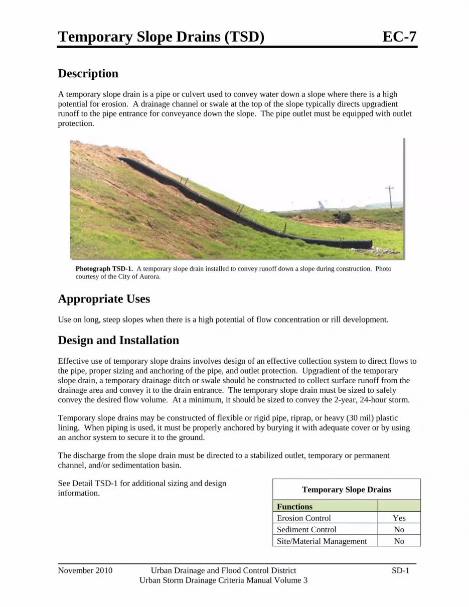
Temporary Slope Drains (TSD) EC-7
November 2010 Urban Drainage and Flood Control District SD-1 Urban Storm Drainage Criteria Manual Volume 3
Photograph TSD-1. A temporary slope drain installed to convey runoff down a slope during construction. Photo courtesy of the City of Aurora.
Description A temporary slope drain is a pipe or culvert used to convey water down a slope where there is a high potential for erosion. A drainage channel or swale at the top of the slope typically directs upgradient runoff to the pipe entrance for conveyance down the slope. The pipe outlet must be equipped with outlet protection.
Appropriate Uses Use on long, steep slopes when there is a high potential of flow concentration or rill development.
Design and Installation Effective use of temporary slope drains involves design of an effective collection system to direct flows to the pipe, proper sizing and anchoring of the pipe, and outlet protection. Upgradient of the temporary slope drain, a temporary drainage ditch or swale should be constructed to collect surface runoff from the drainage area and convey it to the drain entrance. The temporary slope drain must be sized to safely convey the desired flow volume. At a minimum, it should be sized to convey the 2-year, 24-hour storm.
Temporary slope drains may be constructed of flexible or rigid pipe, riprap, or heavy (30 mil) plastic lining. When piping is used, it must be properly anchored by burying it with adequate cover or by using an anchor system to secure it to the ground.
The discharge from the slope drain must be directed to a stabilized outlet, temporary or permanent channel, and/or sedimentation basin.
See Detail TSD-1 for additional sizing and design information.
Temporary Slope Drains
Functions Erosion Control Yes Sediment Control No Site/Material Management No

EC-7 Temporary Slope Drains (TSD)
SD-2 Urban Drainage and Flood Control District November 2010
Urban Storm Drainage Criteria Manual Volume 3
Maintenance and Removal Inspect the entrance for sediment accumulation and remove, as needed. Clogging as a result of sediment deposition at the entrance can lead to ponding upstream causing flooding or overtopping of the slope drain. Inspect the downstream outlet for signs of erosion and stabilize, as needed. It may also be necessary to remove accumulated sediment at the outfall. Inspect pipe anchors to ensure that they are secure. If the pipe is secured by ground cover, ensure erosion has not compromised the depth of cover.
Slope drains should be removed when no longer needed or just prior to installation of permanent slope stabilization measures that cannot be installed with the slope drain in place. When slope drains are removed, the disturbed areas should be covered with topsoil, seeded, mulched or otherwise stabilized as required by the local jurisdiction.

Temporary Slope Drains (TSD) EC-7
November 2010 Urban Drainage and Flood Control District SD-3 Urban Storm Drainage Criteria Manual Volume 3

EC-7 Temporary Slope Drains (TSD)
SD-4 Urban Drainage and Flood Control District November 2010
Urban Storm Drainage Criteria Manual Volume 3

Temporary Outlet Protection (TOP) EC-8
November 2010 Urban Drainage and Flood Control District TOP-1 Urban Storm Drainage Criteria Manual Volume 3
Photograph TOP-1. Riprap outlet protection.
Description Outlet protection helps to reduce erosion immediately downstream of a pipe, culvert, slope drain, rundown or other conveyance with concentrated, high-velocity flows. Typical outlet protection consists of riprap or rock aprons at the conveyance outlet.
Appropriate Uses Outlet protection should be used when a conveyance discharges onto a disturbed area where there is potential for accelerated erosion due to concentrated flow. Outlet protection should be provided where the velocity at the culvert outlet exceeds the maximum permissible velocity of the material in the receiving channel.
Note: This Fact Sheet and detail are for temporary outlet protection, outlets that are intended to be used for less than 2 years. For permanent, long-term outlet protection, see the Major Drainage chapter of Volume 1.
Design and Installation Design outlet protection to handle runoff from the largest drainage area that may be contributing runoff during construction (the drainage area may change as a result of grading). Key in rock, around the entire perimeter of the apron, to a minimum depth of 6 inches for stability. Extend riprap to the height of the culvert or the normal flow depth of the downstream channel, whichever is less. Additional erosion control measures such as vegetative lining, turf reinforcement mat and/or other channel lining methods may be required downstream of the outlet protection if the channel is susceptible to erosion. See Design Detail OP-1 for additional information.
Maintenance and Removal Inspect apron for damage and displaced rocks. If rocks are missing or significantly displaced, repair or replace as necessary. If rocks are continuously missing or displaced, consider increasing the size of the riprap or deeper keying of the perimeter.
Remove sediment accumulated at the outlet before the outlet protection becomes buried and ineffective. When sediment accumulation is noted, check that upgradient BMPs, including inlet protection, are in effective operating condition.
Outlet protection may be removed once the pipe is no longer draining an upstream area, or once the downstream area has been sufficiently stabilized. If the drainage pipe is permanent, outlet protection can be left in place; however, permanent outlet protection should be designed and constructed in accordance with the requirements of the Major Drainage chapter of Volume 2.
Outlet Protection Functions Erosion Control Yes Sediment Control Moderate Site/Material Management No

EC-8 Temporary Outlet Protection (TOP)
TOP-2 Urban Drainage and Flood Control District November 2010
Urban Storm Drainage Criteria Manual Volume 3

Temporary Outlet Protection (TOP) EC-8
November 2010 Urban Drainage and Flood Control District TOP-3 Urban Storm Drainage Criteria Manual Volume 3

Rough Cut Street Control (RCS) EC-9
November 2010 Urban Drainage and Flood Control District RCS-1 Urban Storm Drainage Criteria Manual Volume 3
Photograph RCS-1. Rough cut street controls.
Description Rough cut street controls are rock or earthen berms placed along dirt roadways that are under construction or used for construction access. These temporary berms intercept sheet flow and divert runoff from the roadway, and control erosion by minimizing concentration of flow and reducing runoff velocity.
Appropriate Uses Appropriate uses include:
Temporary dirt construction roadways that have not received roadbase.
Roadways under construction that will not be paved within 14 days of final grading, and that have not yet received roadbase.
Design and Installation Rough cut street controls are designed to redirect sheet flow off the dirt roadway to prevent water from concentrating and eroding the soil. These controls consist of runoff barriers that are constructed at intervals along the road. These barriers are installed perpendicular to the longitudinal slope from the outer edge of the roadside swale to the crown of the road. The barriers are positioned alternately from the right and left side of the road to allow construction traffic to pass in the lane not barred. If construction traffic is expected to be congested and a vehicle tracking control has been constructed, rough-cut street controls may be omitted for 400 feet from the entrance. Runoff from the controls should be directed to another stormwater BMP such as a roadside swale with check dams once removed from the roadway. See Detail RCS-1 for additional information.
Maintenance and Removal Inspect street controls for erosion and stability. If rills are forming in the roadway or cutting through the control berms, place the street controls at shorter intervals. If earthen berms are used, periodic recompaction may be necessary. When rock berms are used, repair and/or replace as necessary when damaged. Street controls may be removed 14 days prior to road surfacing and paving.
Rough Cut Street Control
Functions Erosion Control Yes Sediment Control Moderate Site/Material Management No

EC-9 Rough Cut Street Control (RCS)
RCS-2 Urban Drainage and Flood Control District November 2010
Urban Storm Drainage Criteria Manual Volume 3

Rough Cut Street Control (RCS) EC-9
November 2010 Urban Drainage and Flood Control District RCS-3 Urban Storm Drainage Criteria Manual Volume 3

Earth Dikes and Drainage Swales (ED/DS) EC-10
November 2010 Urban Drainage and Flood Control District ED/DS-1 Urban Storm Drainage Criteria Manual Volume 3
Photograph ED/DS-1. Example of an earth dike used to divert flows at a construction site. Photo courtesy of CDOT.
Description Earth dikes and drainage swales are temporary storm conveyance channels constructed either to divert runoff around slopes or to convey runoff to additional sediment control BMPs prior to discharge of runoff from a site. Drainage swales may be lined or unlined, but if an unlined swale is used, it must be well compacted and capable of resisting erosive velocities.
Appropriate Uses Earth dikes and drainage swales are typically used to control the flow path of runoff at a construction site by diverting runoff around areas prone to erosion, such as steep slopes. Earth dikes and drainage swales may also be constructed as temporary conveyance features. This will direct runoff to additional sediment control treatment BMPs, such as sediment traps or basins.
Design and Installation When earth dikes are used to divert water for slope protection, the earth dike typically consists of a horizontal ridge of soil placed perpendicular to the slope and angled slightly to provide drainage along the contour. The dike is used in conjunction with a swale or a small channel upslope of the berm to convey the diverted water. Temporary diversion dikes can be constructed by excavation of a V-shaped trench or ditch and placement of the fill on the downslope side of the cut. There are two types of placement for temporary slope diversion dikes:
A dike located at the top of a slope to divert upland runoff away from the disturbed area and convey it in a temporary or permanent channel.
A diversion dike located at the base or mid-slope of a disturbed area to intercept runoff and reduce the effective slope length.
Depending on the project, either an earth dike or drainage swale may be more appropriate. If there is a need for cut on the project, then an excavated drainage swale may be better suited. When the project is primarily fill, then a conveyance constructed using a berm may be the better option.
All dikes or swales receiving runoff from a disturbed area should direct stormwater to a sediment control BMP such as a sediment trap or basin.
Earth Dikes and Drainage Swales
Functions Erosion Control Yes Sediment Control Moderate Site/Material Management No

EC-10 Earth Dikes and Drainage Swales (ED/DS)
ED/DS-2 Urban Drainage and Flood Control District November 2010
Urban Storm Drainage Criteria Manual Volume 3
Unlined dikes or swales should only be used for intercepting sheet flow runoff and are not intended for diversion of concentrated flows.
Details with notes are provided for several design variations, including:
ED-1. Unlined Earth Dike formed by Berm
DS-1. Unlined Excavated Swale
DS-2. Unlined Swale Formed by Cut and Fill
DS-3. ECB-lined Swale
DS-4. Synthetic-lined Swale
DS-5. Riprap-lined Swale
The details also include guidance on permissible velocities for cohesive channels if unlined approaches will be used.
Maintenance and Removal Inspect earth dikes for stability, compaction, and signs of erosion and repair. Inspect side slopes for erosion and damage to erosion control fabric. Stabilize slopes and repair fabric as necessary. If there is reoccurring extensive damage, consider installing rock check dams or lining the channel with riprap.
If drainage swales are not permanent, remove dikes and fill channels when the upstream area is stabilized. Stabilize the fill or disturbed area immediately following removal by revegetation or other permanent stabilization method approved by the local jurisdiction.

Earth Dikes and Drainage Swales (ED/DS) EC-10
November 2010 Urban Drainage and Flood Control District ED/DS-3 Urban Storm Drainage Criteria Manual Volume 3

EC-10 Earth Dikes and Drainage Swales (ED/DS)
ED/DS-4 Urban Drainage and Flood Control District November 2010
Urban Storm Drainage Criteria Manual Volume 3
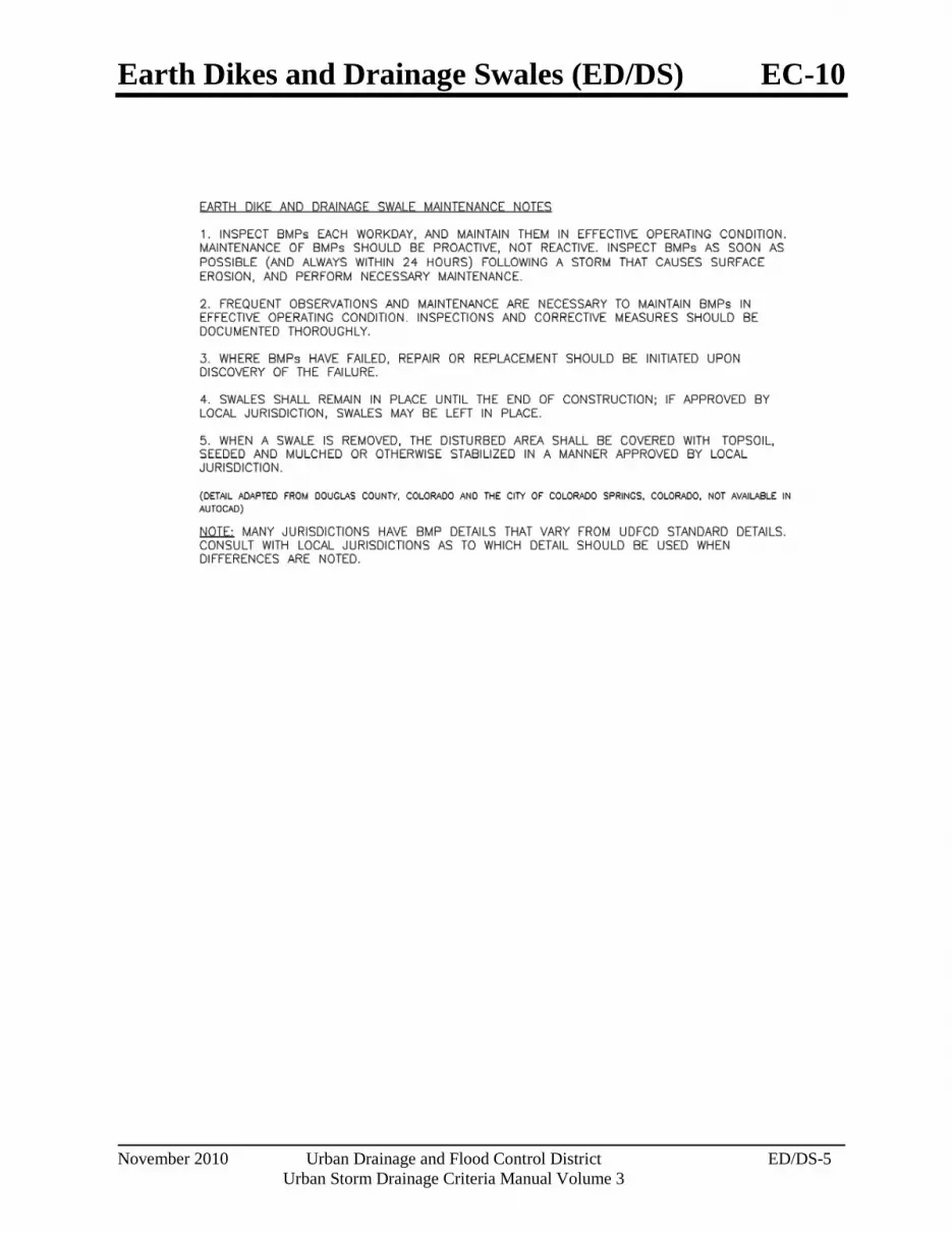
Earth Dikes and Drainage Swales (ED/DS) EC-10
November 2010 Urban Drainage and Flood Control District ED/DS-5 Urban Storm Drainage Criteria Manual Volume 3
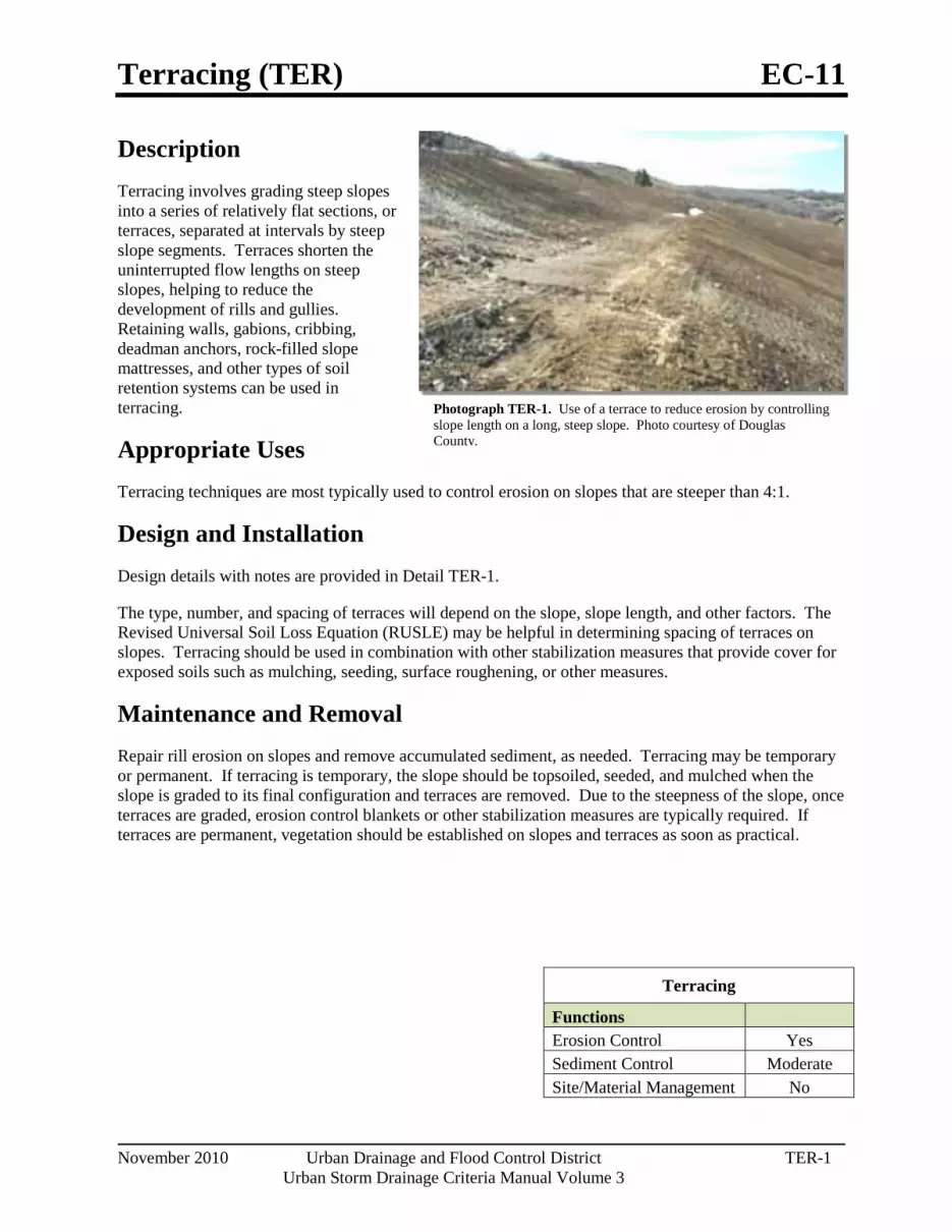
Terracing (TER) EC-11
November 2010 Urban Drainage and Flood Control District TER-1 Urban Storm Drainage Criteria Manual Volume 3
Photograph TER-1. Use of a terrace to reduce erosion by controlling slope length on a long, steep slope. Photo courtesy of Douglas County.
Description Terracing involves grading steep slopes into a series of relatively flat sections, or terraces, separated at intervals by steep slope segments. Terraces shorten the uninterrupted flow lengths on steep slopes, helping to reduce the development of rills and gullies. Retaining walls, gabions, cribbing, deadman anchors, rock-filled slope mattresses, and other types of soil retention systems can be used in terracing.
Appropriate Uses Terracing techniques are most typically used to control erosion on slopes that are steeper than 4:1.
Design and Installation Design details with notes are provided in Detail TER-1.
The type, number, and spacing of terraces will depend on the slope, slope length, and other factors. The Revised Universal Soil Loss Equation (RUSLE) may be helpful in determining spacing of terraces on slopes. Terracing should be used in combination with other stabilization measures that provide cover for exposed soils such as mulching, seeding, surface roughening, or other measures.
Maintenance and Removal Repair rill erosion on slopes and remove accumulated sediment, as needed. Terracing may be temporary or permanent. If terracing is temporary, the slope should be topsoiled, seeded, and mulched when the slope is graded to its final configuration and terraces are removed. Due to the steepness of the slope, once terraces are graded, erosion control blankets or other stabilization measures are typically required. If terraces are permanent, vegetation should be established on slopes and terraces as soon as practical.
Terracing
Functions Erosion Control Yes Sediment Control Moderate Site/Material Management No

EC-11 Terracing (TER)
TER-2 Urban Drainage and Flood Control District November 2010
Urban Storm Drainage Criteria Manual Volume 3

Check Dams (CD) EC-12
November 2010 Urban Drainage and Flood Control District CD-1 Urban Storm Drainage Criteria Manual Volume 3
Photograph CD-1. Rock check dams in a roadside ditch. Photo courtesy of WWE.
Description Check dams are temporary grade control structures placed in drainage channels to limit the erosivity of stormwater by reducing flow velocity. Check dams are typically constructed from rock, gravel bags, sand bags, or sometimes, proprietary devices. Reinforced check dams are typically constructed from rock and wire gabion. Although the primary function of check dams is to reduce the velocity of concentrated flows, a secondary benefit is sediment trapping upstream of the structure.
Appropriate Uses Use as a grade control for temporary drainage ditches or swales until final soil stabilization measures are established upstream and downstream. Check dams can be used on mild or moderately steep slopes. Check dams may be used under the following conditions:
As temporary grade control facilities along waterways until final stabilization is established.
Along permanent swales that need protection prior to installation of a non-erodible lining.
Along temporary channels, ditches or swales that need protection where construction of a non-erodible lining is not practicable.
Reinforced check dams should be used in areas subject to high flow velocities.
Design and Installation Place check dams at regularly spaced intervals along the drainage swale or ditch. Check dams heights should allow for pools to develop upstream of each check dam, extending to the downstream toe of the check dam immediately upstream.
When rock is used for the check dam, place rock mechanically or by hand. Do not dump rocks into the drainage channel. Where multiple check dams are used, the top of the lower dam should be at the same elevation as the toe of the upper dam.
When reinforced check dams are used, install erosion control fabric under and around the check dam to prevent erosion on the upstream and downstream sides. Each section of the dam should be keyed in to reduce the potential for washout or undermining. A rock apron upstream and downstream of the dam may be necessary to further control erosion.
Check Dams
Functions Erosion Control Yes Sediment Control Moderate Site/Material Management No

EC-12 Check Dams (CD)
CD-2 Urban Drainage and Flood Control District November 2010
Urban Storm Drainage Criteria Manual Volume 3
Design details with notes are provided for the following types of check dams:
Rock Check Dams (CD-1)
Reinforced Check Dams (CD-2)
Sediment control logs may also be used as check dams; however, silt fence is not appropriate for use as a check dam. Many jurisdictions also prohibit or discourage use of straw bales for this purpose.
Maintenance and Removal Replace missing rocks causing voids in the check dam. If gravel bags or sandbags are used, replace or repair torn or displaced bags.
Remove accumulated sediment, as needed to maintain BMP effectiveness, typically before the sediment depth upstream of the check dam is within ½ of the crest height. Remove accumulated sediment prior to mulching, seeding, or chemical soil stabilization. Removed sediment can be incorporated into the earthwork with approval from the Project Engineer, or disposed of at an alternate location in accordance with the standard specifications.
Check dams constructed in permanent swales should be removed when perennial grasses have become established, or immediately prior to installation of a non-erodible lining. All of the rock and accumulated sediment should be removed, and the area seeded and mulched, or otherwise stabilized.

Check Dams (CD) EC-12
November 2010 Urban Drainage and Flood Control District CD-3 Urban Storm Drainage Criteria Manual Volume 3
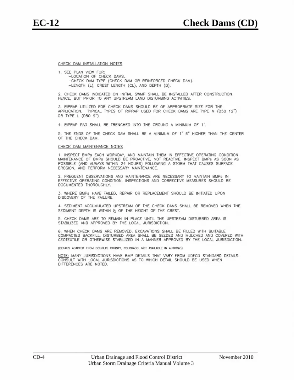
EC-12 Check Dams (CD)
CD-4 Urban Drainage and Flood Control District November 2010
Urban Storm Drainage Criteria Manual Volume 3
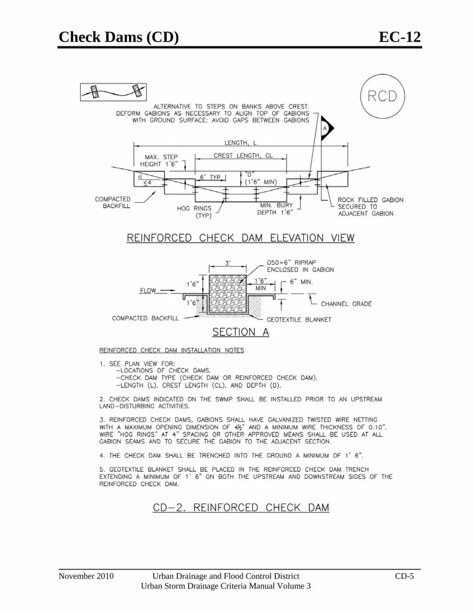
Check Dams (CD) EC-12
November 2010 Urban Drainage and Flood Control District CD-5 Urban Storm Drainage Criteria Manual Volume 3

EC-12 Check Dams (CD)
CD-6 Urban Drainage and Flood Control District November 2010
Urban Storm Drainage Criteria Manual Volume 3

Streambank Stabilization (SS) EC-13
November 2010 Urban Drainage and Flood Control District SS-1 Urban Storm Drainage Criteria Manual Volume 3
Photograph SS-1. Streambank stabilization using geotextiles following installation of a permanent in-stream grade control structure.
Description Streambank stabilization involves a combination of erosion and sediment control practices to protect streams, banks, and in-stream habitat from accelerated erosion. BMPs associated with streambank stabilization may include protection of existing vegetation, check dams/grade control, temporary and permanent seeding, outlet protection, rolled erosion control products, temporary diversions, dewatering operations and bioengineering practices such as brush layering, live staking and fascines.
Appropriate Uses Streambank stabilization may be a construction activity in and of itself, or it may be in conjunction with a broader construction project that discharges to a waterway that is susceptible to accelerated erosion due to increases in the rate and volume of stormwater runoff. Depending on the health of the stream, water quality sampling and testing may be advisable prior to and/or during construction to evaluate health and stability of the stream and potential effects from adjacent construction activities.
Design and Installation Streambank stabilization consists of protecting the stream in a variety of ways to minimize negative effects to the stream environment. The following lists the minimum requirements necessary for construction streambank stabilization:
Protect existing vegetation along the stream bank in accordance with the Vegetated Buffers and Protection of Existing Vegetation Fact Sheets. Preserving a riparian buffer along the streambank will help to remove sediment and decrease runoff rates from the disturbed area.
Outside the riparian buffer, provide sediment control in the form of a silt fence or equivalent sediment control practice along the entire length of the stream that will receive runoff from the area of disturbance. In some cases, a double-layered perimeter control may be justified adjacent to sensitive receiving waters and wetlands to provide additional protection.
Stabilize all areas that will be draining to the stream. Use rolled erosion control products, temporary or permanent seeding, or other appropriate measures.
Ensure all point discharges entering the stream are adequately armored with a velocity dissipation device and appropriate outlet protection.
See individual design details and notes for the various BMPs referenced in this practice. Additional information on bioengineering techniques for stream stabilization can be
Streambank Stabilization
Functions Erosion Control Yes Sediment Control No Site/Material Management No

EC-13 Streambank Stabilization (SS)
SS-2 Urban Drainage and Flood Control District November 2010
Urban Storm Drainage Criteria Manual Volume 3
found in the Major Drainage chapter of Volume 1 and additional guidance on BMPs for working in waterways can be found in UDFCD’s Best Management Practices for Construction in Waterways Training Manual.
Maintenance and Removal Inspect BMPs protecting the stream for damage on a daily basis. Maintain, repair, or replace damaged BMPs following the guidance provided in individual BMP Fact Sheets for practices that are implemented. Some streambank stabilization BMPs are intended to remain in place as vegetation matures (e.g. erosion control blankets protecting seeded stream banks and turf reinforcement mats).
For BMPs that are not to remain in place as a part of final stabilization such as silt fence and other temporary measures, BMPs should be removed when all land disturbing activities have ceased and areas have been permanently stabilized.

Wind Erosion/Dust Control (DC) EC-14
November 2010 Urban Drainage and Flood Control District DC-1 Urban Storm Drainage Criteria Manual Volume 3
Photograph DC-1. Water truck used for dust suppression. Photo courtesy of Douglas County.
Description Wind erosion and dust control BMPs help to keep soil particles from entering the air as a result of land disturbing construction activities. These BMPs include a variety of practices generally focused on either graded disturbed areas or construction roadways. For graded areas, practices such as seeding and mulching, use of soil binders, site watering, or other practices that provide prompt surface cover should be used. For construction roadways, road watering and stabilized surfaces should be considered.
Appropriate Uses Dust control measures should be used on any site where dust poses a problem to air quality. Dust control is important to control for the health of construction workers and surrounding waterbodies.
Design and Installation The following construction BMPs can be used for dust control:
An irrigation/sprinkler system can be used to wet the top layer of disturbed soil to help keep dry soil particles from becoming airborne.
Seeding and mulching can be used to stabilize disturbed surfaces and reduce dust emissions.
Protecting existing vegetation can help to slow wind velocities across the ground surface, thereby limiting the likelihood of soil particles to become airborne.
Spray-on soil binders form a bond between soil particles keeping them grounded. Chemical treatments may require additional permitting requirements. Potential impacts to surrounding waterways and habitat must be considered prior to use.
Placing rock on construction roadways and entrances will help keep dust to a minimum across the construction site.
Wind fences can be installed on site to reduce wind speeds. Install fences perpendicular to the prevailing wind direction for maximum effectiveness.
Maintenance and Removal When using an irrigation/sprinkler control system to aid in dust control, be careful not to overwater. Overwatering will cause construction vehicles to track mud off-site.
Wind Erosion Control/ Dust Control
Functions Erosion Control Yes Sediment Control No Site/Material Management Moderate

Concrete Washout Area (CWA) MM-1
November 2010 Urban Drainage and Flood Control District CWA-1 Urban Storm Drainage Criteria Manual Volume 3
Photograph CWA-1. Example of concrete washout area. Note gravel tracking pad for access and sign.
Description Concrete waste management involves designating and properly managing a specific area of the construction site as a concrete washout area. A concrete washout area can be created using one of several approaches designed to receive wash water from washing of tools and concrete mixer chutes, liquid concrete waste from dump trucks, mobile batch mixers, or pump trucks. Three basic approaches are available: excavation of a pit in the ground, use of an above ground storage area, or use of prefabricated haul-away concrete washout containers. Surface discharges of concrete washout water from construction sites are prohibited.
Appropriate Uses Concrete washout areas must be designated on all sites that will generate concrete wash water or liquid concrete waste from onsite concrete mixing or concrete delivery.
Because pH is a pollutant of concern for washout activities, when unlined pits are used for concrete washout, the soil must have adequate buffering capacity to result in protection of state groundwater standards; otherwise, a liner/containment must be used. The following management practices are recommended to prevent an impact from unlined pits to groundwater:
The use of the washout site should be temporary (less than 1 year), and
The washout site should be not be located in an area where shallow groundwater may be present, such as near natural drainages, springs, or wetlands.
Design and Installation Concrete washout activities must be conducted in a manner that does not contribute pollutants to surface waters or stormwater runoff. Concrete washout areas may be lined or unlined excavated pits in the ground, commercially manufactured prefabricated washout containers, or aboveground holding areas constructed of berms, sandbags or straw bales with a plastic liner.
Although unlined washout areas may be used, lined pits may be required to protect groundwater under certain conditions.
Do not locate an unlined washout area within 400 feet of any natural drainage pathway or waterbody or within 1,000 feet of any wells or drinking water sources. Even for lined concrete washouts, it is advisable to locate the facility away from waterbodies and drainage paths. If site constraints make these
Concrete Washout Area Functions Erosion Control No Sediment Control No Site/Material Management Yes
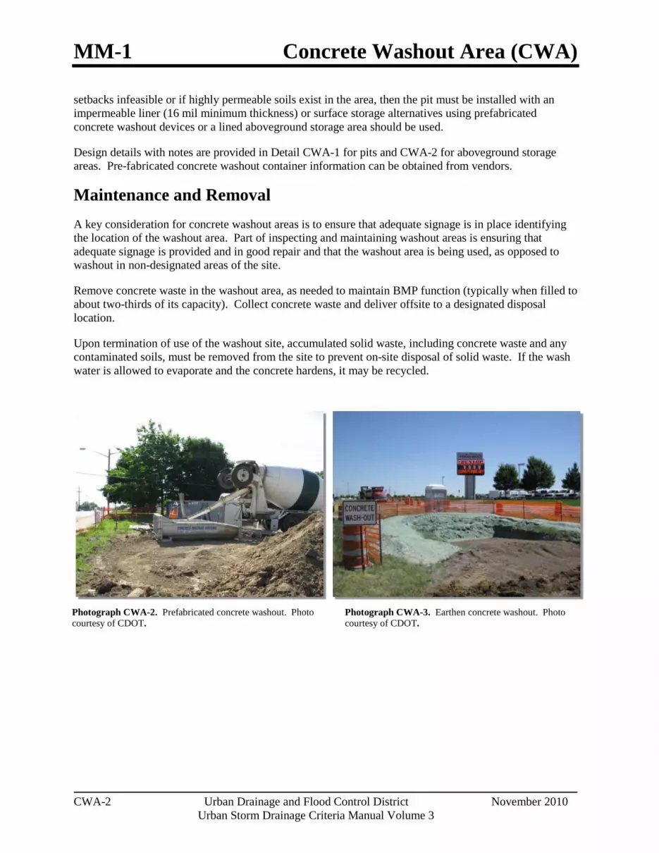
MM-1 Concrete Washout Area (CWA)
CWA-2 Urban Drainage and Flood Control District November 2010
Urban Storm Drainage Criteria Manual Volume 3
setbacks infeasible or if highly permeable soils exist in the area, then the pit must be installed with an impermeable liner (16 mil minimum thickness) or surface storage alternatives using prefabricated concrete washout devices or a lined aboveground storage area should be used.
Design details with notes are provided in Detail CWA-1 for pits and CWA-2 for aboveground storage areas. Pre-fabricated concrete washout container information can be obtained from vendors.
Maintenance and Removal A key consideration for concrete washout areas is to ensure that adequate signage is in place identifying the location of the washout area. Part of inspecting and maintaining washout areas is ensuring that adequate signage is provided and in good repair and that the washout area is being used, as opposed to washout in non-designated areas of the site.
Remove concrete waste in the washout area, as needed to maintain BMP function (typically when filled to about two-thirds of its capacity). Collect concrete waste and deliver offsite to a designated disposal location.
Upon termination of use of the washout site, accumulated solid waste, including concrete waste and any contaminated soils, must be removed from the site to prevent on-site disposal of solid waste. If the wash water is allowed to evaporate and the concrete hardens, it may be recycled.
Photograph CWA-3. Earthen concrete washout. Photo courtesy of CDOT.
Photograph CWA-2. Prefabricated concrete washout. Photo courtesy of CDOT.

Concrete Washout Area (CWA) MM-1
November 2010 Urban Drainage and Flood Control District CWA-3 Urban Storm Drainage Criteria Manual Volume 3
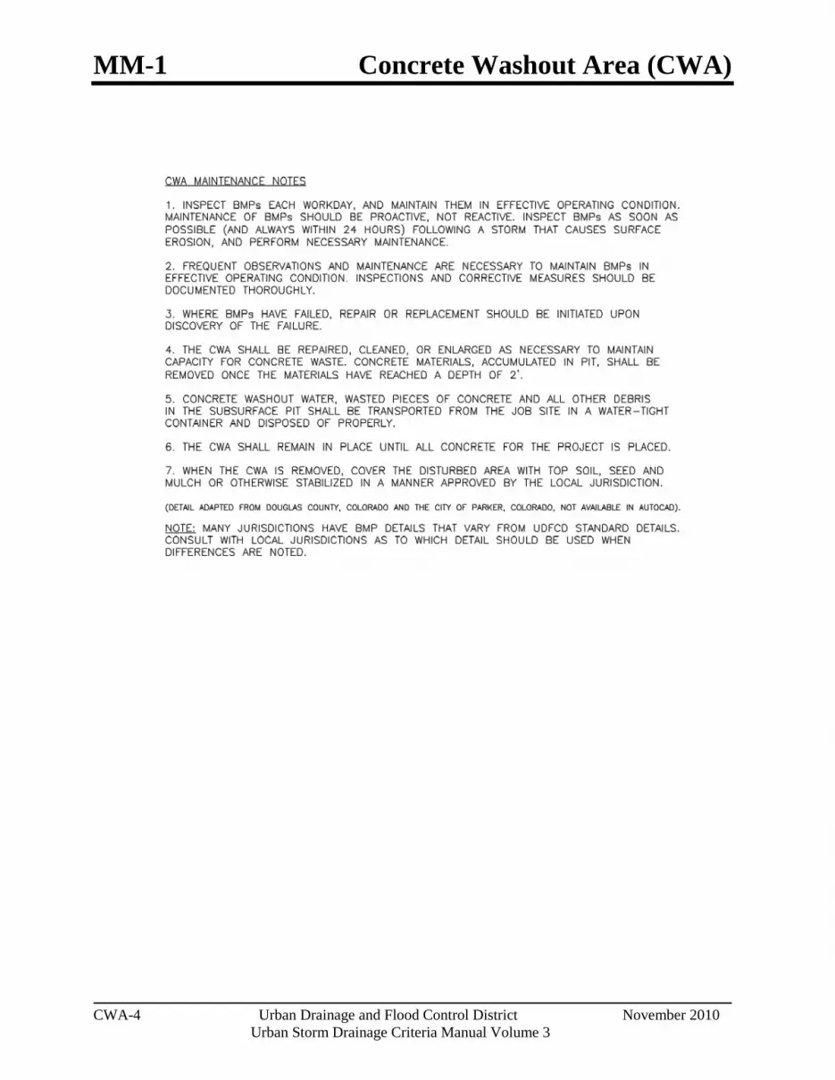
MM-1 Concrete Washout Area (CWA)
CWA-4 Urban Drainage and Flood Control District November 2010
Urban Storm Drainage Criteria Manual Volume 3
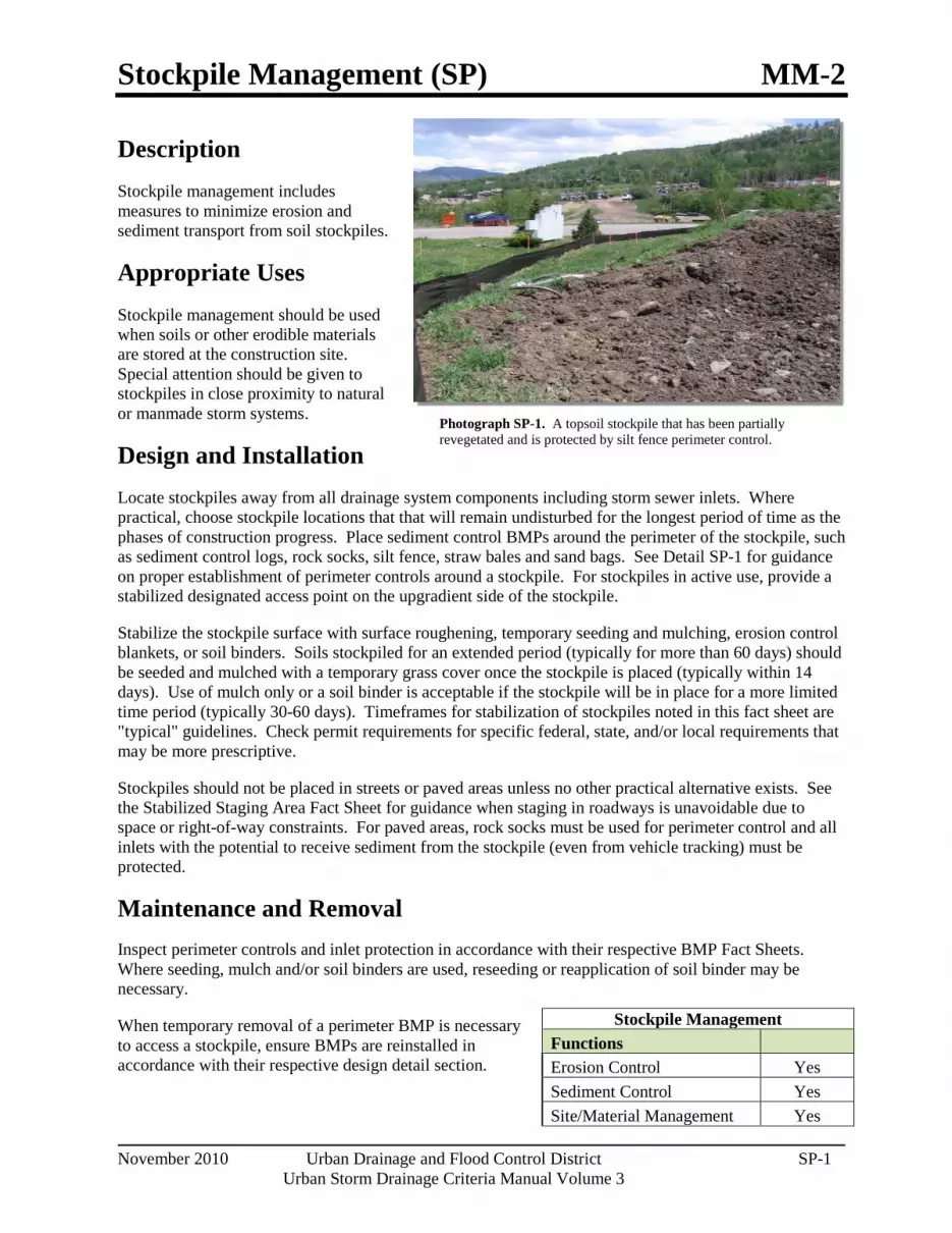
Stockpile Management (SP) MM-2
November 2010 Urban Drainage and Flood Control District SP-1 Urban Storm Drainage Criteria Manual Volume 3
Photograph SP-1. A topsoil stockpile that has been partially revegetated and is protected by silt fence perimeter control.
Description Stockpile management includes measures to minimize erosion and sediment transport from soil stockpiles.
Appropriate Uses Stockpile management should be used when soils or other erodible materials are stored at the construction site. Special attention should be given to stockpiles in close proximity to natural or manmade storm systems.
Design and Installation Locate stockpiles away from all drainage system components including storm sewer inlets. Where practical, choose stockpile locations that that will remain undisturbed for the longest period of time as the phases of construction progress. Place sediment control BMPs around the perimeter of the stockpile, such as sediment control logs, rock socks, silt fence, straw bales and sand bags. See Detail SP-1 for guidance on proper establishment of perimeter controls around a stockpile. For stockpiles in active use, provide a stabilized designated access point on the upgradient side of the stockpile.
Stabilize the stockpile surface with surface roughening, temporary seeding and mulching, erosion control blankets, or soil binders. Soils stockpiled for an extended period (typically for more than 60 days) should be seeded and mulched with a temporary grass cover once the stockpile is placed (typically within 14 days). Use of mulch only or a soil binder is acceptable if the stockpile will be in place for a more limited time period (typically 30-60 days). Timeframes for stabilization of stockpiles noted in this fact sheet are "typical" guidelines. Check permit requirements for specific federal, state, and/or local requirements that may be more prescriptive.
Stockpiles should not be placed in streets or paved areas unless no other practical alternative exists. See the Stabilized Staging Area Fact Sheet for guidance when staging in roadways is unavoidable due to space or right-of-way constraints. For paved areas, rock socks must be used for perimeter control and all inlets with the potential to receive sediment from the stockpile (even from vehicle tracking) must be protected.
Maintenance and Removal Inspect perimeter controls and inlet protection in accordance with their respective BMP Fact Sheets. Where seeding, mulch and/or soil binders are used, reseeding or reapplication of soil binder may be necessary.
When temporary removal of a perimeter BMP is necessary to access a stockpile, ensure BMPs are reinstalled in accordance with their respective design detail section.
Stockpile Management Functions Erosion Control Yes Sediment Control Yes Site/Material Management Yes
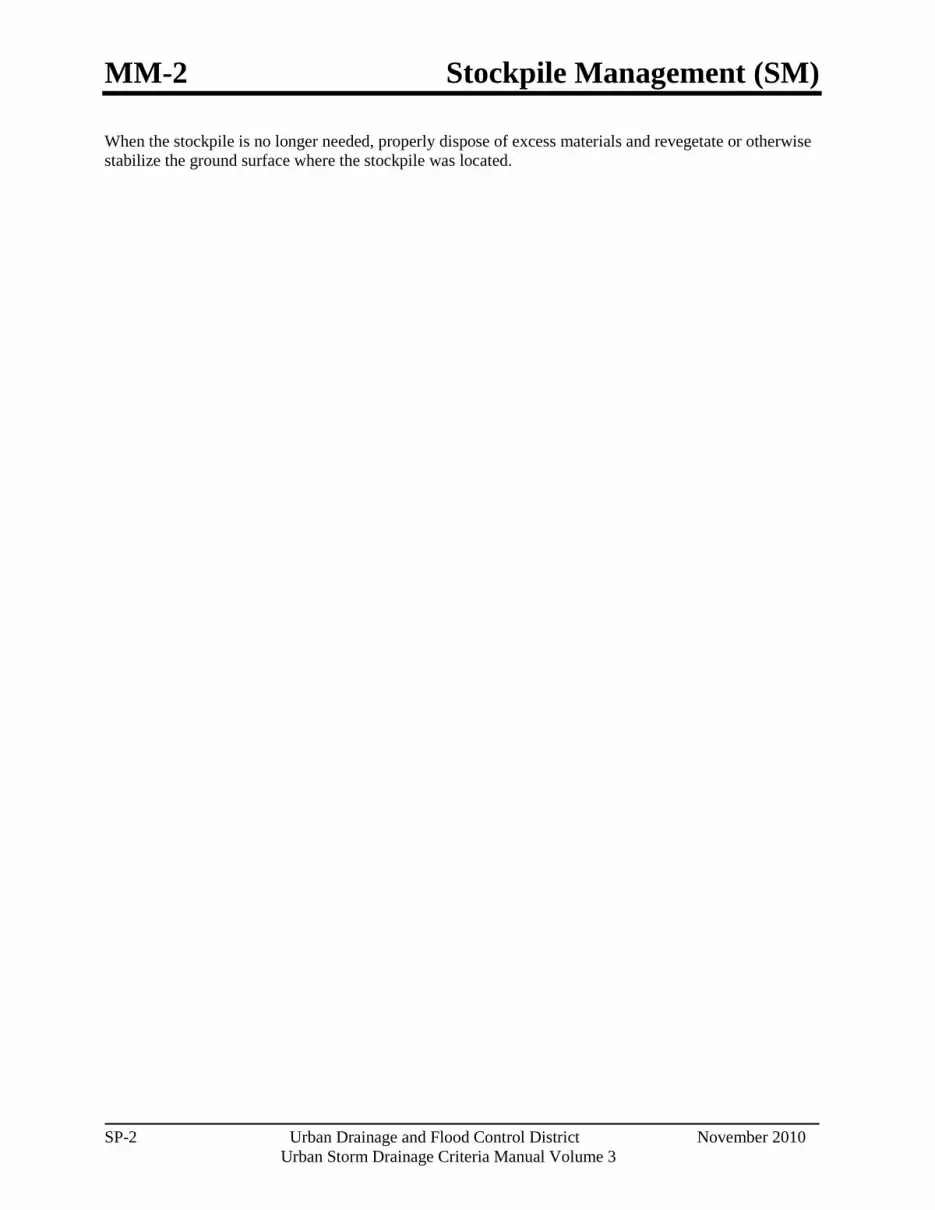
MM-2 Stockpile Management (SM)
SP-2 Urban Drainage and Flood Control District November 2010
Urban Storm Drainage Criteria Manual Volume 3
When the stockpile is no longer needed, properly dispose of excess materials and revegetate or otherwise stabilize the ground surface where the stockpile was located.
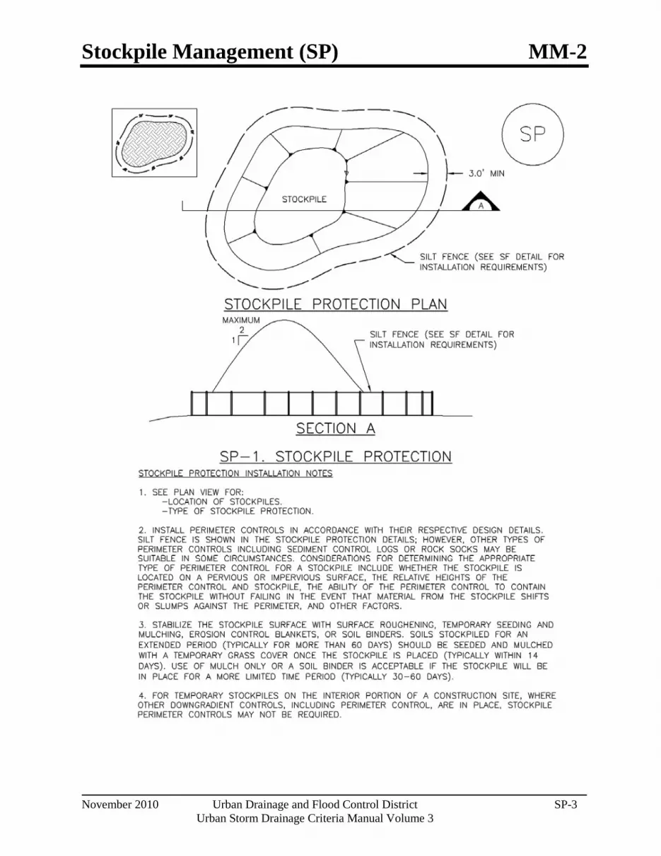
Stockpile Management (SP) MM-2
November 2010 Urban Drainage and Flood Control District SP-3 Urban Storm Drainage Criteria Manual Volume 3
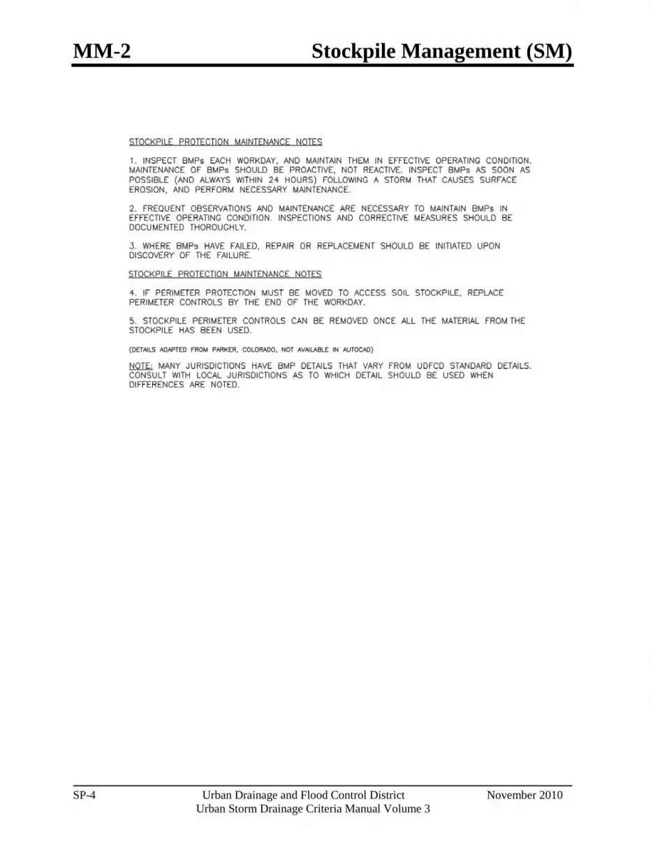
MM-2 Stockpile Management (SM)
SP-4 Urban Drainage and Flood Control District November 2010
Urban Storm Drainage Criteria Manual Volume 3

Stockpile Management (SP) MM-2
November 2010 Urban Drainage and Flood Control District SP-5 Urban Storm Drainage Criteria Manual Volume 3

MM-2 Stockpile Management (SM)
SP-6 Urban Drainage and Flood Control District November 2010
Urban Storm Drainage Criteria Manual Volume 3

Good Housekeeping Practices (GH) MM-3
November 2010 Urban Drainage and Flood Control District GH-1 Urban Storm Drainage Criteria Manual Volume 3
Photographs GH-1 and GH-2. Proper materials storage and secondary containment for fuel tanks are important good housekeeping practices. Photos courtesy of CDOT and City of Aurora.
Description Implement construction site good housekeeping practices to prevent pollution associated with solid, liquid and hazardous construction-related materials and wastes. Stormwater Management Plans (SWMPs) should clearly specify BMPs including these good housekeeping practices:
Provide for waste management.
Establish proper building material staging areas.
Designate paint and concrete washout areas.
Establish proper equipment/vehicle fueling and maintenance practices.
Control equipment/vehicle washing and allowable non-stormwater discharges.
Develop a spill prevention and response plan.
Acknowledgement: This Fact Sheet is based directly on EPA guidance provided in Developing Your Stormwater Pollution Prevent Plan (EPA 2007).
Appropriate Uses Good housekeeping practices are necessary at all construction sites.
Design and Installation The following principles and actions should be addressed in SWMPs:
Provide for Waste Management. Implement management procedures and practices to prevent or reduce the exposure and transport of pollutants in stormwater from solid, liquid and sanitary wastes that will be generated at the site. Practices such as trash disposal, recycling, proper material handling, and cleanup measures can reduce the potential for stormwater runoff to pick up construction site wastes and discharge them to surface waters. Implement a comprehensive set of waste-management practices for hazardous or toxic materials, such as paints, solvents, petroleum products, pesticides, wood preservatives, acids, roofing tar, and other materials. Practices should include storage, handling, inventory, and cleanup procedures, in case of spills. Specific practices that should be considered include:
Solid or Construction Waste
o Designate trash and bulk waste-collection areas on-site.
Good Housekeeping
Functions Erosion Control No Sediment Control No Site/Material Management Yes

MM-3 Good Housekeeping Practices (GH)
GH-2 Urban Drainage and Flood Control District November 2010
Urban Storm Drainage Criteria Manual Volume 3
Photograph GH-3. Locate portable toilet facilities on level surfaces away from waterways and storm drains. Photo courtesy of WWE.
o Recycle materials whenever possible (e.g., paper, wood, concrete, oil).
o Segregate and provide proper disposal options for hazardous material wastes.
o Clean up litter and debris from the construction site daily.
o Locate waste-collection areas away from streets, gutters, watercourses, and storm drains. Waste-collection areas (dumpsters, and such) are often best located near construction site entrances to minimize traffic on disturbed soils. Consider secondary containment around waste collection areas to minimize the likelihood of contaminated discharges.
o Empty waste containers before they are full and overflowing.
Sanitary and Septic Waste
o Provide convenient, well-maintained, and properly located toilet facilities on-site.
o Locate toilet facilities away from storm drain inlets and waterways to prevent accidental spills and contamination of stormwater.
o Maintain clean restroom facilities and empty portable toilets regularly.
o Where possible, provide secondary containment pans under portable toilets.
o Provide tie-downs or stake-downs for portable toilets.
o Educate employees, subcontractors, and suppliers on locations of facilities.
o Treat or dispose of sanitary and septic waste in accordance with state or local regulations. Do not discharge or bury wastewater at the construction site.
o Inspect facilities for leaks. If found, repair or replace immediately.
o Special care is necessary during maintenance (pump out) to ensure that waste and/or biocide are not spilled on the ground.
Hazardous Materials and Wastes
o Develop and implement employee and subcontractor education, as needed, on hazardous and toxic waste handling, storage, disposal, and cleanup.
o Designate hazardous waste-collection areas on-site.
o Place all hazardous and toxic material wastes in secondary containment.

Good Housekeeping Practices (GH) MM-3
November 2010 Urban Drainage and Flood Control District GH-3 Urban Storm Drainage Criteria Manual Volume 3
o Hazardous waste containers should be inspected to ensure that all containers are labeled properly and that no leaks are present.
Establish Proper Building Material Handling and Staging Areas. The SWMP should include comprehensive handling and management procedures for building materials, especially those that are hazardous or toxic. Paints, solvents, pesticides, fuels and oils, other hazardous materials or building materials that have the potential to contaminate stormwater should be stored indoors or under cover whenever possible or in areas with secondary containment. Secondary containment measures prevent a spill from spreading across the site and may include dikes, berms, curbing, or other containment methods. Secondary containment techniques should also ensure the protection of groundwater. Designate staging areas for activities such as fueling vehicles, mixing paints, plaster, mortar, and other potential pollutants. Designated staging areas enable easier monitoring of the use of materials and clean up of spills. Training employees and subcontractors is essential to the success of this pollution prevention principle. Consider the following specific materials handling and staging practices:
o Train employees and subcontractors in proper handling and storage practices.
o Clearly designate site areas for staging and storage with signs and on construction drawings. Staging areas should be located in areas central to the construction site. Segment the staging area into sub-areas designated for vehicles, equipment, or stockpiles. Construction entrances and exits should be clearly marked so that delivery vehicles enter/exit through stabilized areas with vehicle tracking controls (See Vehicle Tracking Control Fact Sheet).
o Provide storage in accordance with Spill Protection, Control and Countermeasures (SPCC) requirements and plans and provide cover and impermeable perimeter control, as necessary, for hazardous materials and contaminated soils that must be stored on site.
o Ensure that storage containers are regularly inspected for leaks, corrosion, support or foundation failure, or other signs of deterioration and tested for soundness.
o Reuse and recycle construction materials when possible.
Designate Concrete Washout Areas. Concrete contractors should be encouraged to use the washout facilities at their own plants or dispatch facilities when feasible; however, concrete washout commonly occurs on construction sites. If it is necessary to provide for concrete washout areas on-site, designate specific washout areas and design facilities to handle anticipated washout water. Washout areas should also be provided for paint and stucco operations. Because washout areas can be a source of pollutants from leaks or spills, care must be taken with regard to their placement and proper use. See the Concrete Washout Area Fact Sheet for detailed guidance.
Both self-constructed and prefabricated washout containers can fill up quickly when concrete, paint, and stucco work are occurring on large portions of the site. Be sure to check for evidence that contractors are using the washout areas and not dumping materials onto the ground or into drainage facilities. If the washout areas are not being used regularly, consider posting additional signage, relocating the facilities to more convenient locations, or providing training to workers and contractors.
When concrete, paint, or stucco is part of the construction process, consider these practices which will help prevent contamination of stormwater. Include the locations of these areas and the maintenance and inspection procedures in the SWMP.

MM-3 Good Housekeeping Practices (GH)
GH-4 Urban Drainage and Flood Control District November 2010
Urban Storm Drainage Criteria Manual Volume 3
o Do not washout concrete trucks or equipment into storm drains, streets, gutters, uncontained areas, or streams. Only use designated washout areas.
o Establish washout areas and advertise their locations with signs. Ensure that signage remains in good repair.
o Provide adequate containment for the amount of wash water that will be used.
o Inspect washout structures daily to detect leaks or tears and to identify when materials need to be removed.
o Dispose of materials properly. The preferred method is to allow the water to evaporate and to recycle the hardened concrete. Full service companies may provide dewatering services and should dispose of wastewater properly. Concrete wash water can be highly polluted. It should not be discharged to any surface water, storm sewer system, or allowed to infiltrate into the ground in the vicinity of waterbodies. Washwater should not be discharged to a sanitary sewer system without first receiving written permission from the system operator.
Establish Proper Equipment/Vehicle Fueling and Maintenance Practices. Create a clearly designated on-site fueling and maintenance area that is clean and dry. The on-site fueling area should have a spill kit, and staff should know how to use it. If possible, conduct vehicle fueling and maintenance activities in a covered area. Consider the following practices to help prevent the discharge of pollutants to stormwater from equipment/vehicle fueling and maintenance. Include the locations of designated fueling and maintenance areas and inspection and maintenance procedures in the SWMP.
o Train employees and subcontractors in proper fueling procedures (stay with vehicles during fueling, proper use of pumps, emergency shutoff valves, etc.).
o Inspect on-site vehicles and equipment regularly for leaks, equipment damage, and other service problems.
o Clearly designate vehicle/equipment service areas away from drainage facilities and watercourses to prevent stormwater run-on and runoff.
o Use drip pans, drip cloths, or absorbent pads when replacing spent fluids.
o Collect all spent fluids, store in appropriate labeled containers in the proper storage areas, and recycle fluids whenever possible.
Control Equipment/Vehicle Washing and Allowable Non-Stormwater Discharges. Implement practices to prevent contamination of surface and groundwater from equipment and vehicle wash water. Representative practices include:
o Educate employees and subcontractors on proper washing procedures.
o Use off-site washing facilities, when available.
o Clearly mark the washing areas and inform workers that all washing must occur in this area.
o Contain wash water and treat it using BMPs. Infiltrate washwater when possible, but maintain separation from drainage paths and waterbodies.

Good Housekeeping Practices (GH) MM-3
November 2010 Urban Drainage and Flood Control District GH-5 Urban Storm Drainage Criteria Manual Volume 3
o Use high-pressure water spray at vehicle washing facilities without detergents. Water alone can remove most dirt adequately.
o Do not conduct other activities, such as vehicle repairs, in the wash area.
o Include the location of the washing facilities and the inspection and maintenance procedures in the SWMP.
Develop a Spill Prevention and Response Plan. Spill prevention and response procedures must be identified in the SWMP. Representative procedures include identifying ways to reduce the chance of spills, stop the source of spills, contain and clean up spills, dispose of materials contaminated by spills, and train personnel responsible for spill prevention and response. The plan should also specify material handling procedures and storage requirements and ensure that clear and concise spill cleanup procedures are provided and posted for areas in which spills may potentially occur. When developing a spill prevention plan, include the following:
o Note the locations of chemical storage areas, storm drains, tributary drainage areas, surface waterbodies on or near the site, and measures to stop spills from leaving the site.
o Provide proper handling and safety procedures for each type of waste. Keep Material Safety Data Sheets (MSDSs) for chemical used on site with the SWMP.
o Establish an education program for employees and subcontractors on the potential hazards to humans and the environment from spills and leaks.
o Specify how to notify appropriate authorities, such as police and fire departments, hospitals, or municipal sewage treatment facilities to request assistance. Emergency procedures and contact numbers should be provided in the SWMP and posted at storage locations.
o Describe the procedures, equipment and materials for immediate cleanup of spills and proper disposal.
o Identify personnel responsible for implementing the plan in the event of a spill. Update the spill prevention plan and clean up materials as changes occur to the types of chemicals stored and used at the facility.

MM-3 Good Housekeeping Practices (GH)
GH-6 Urban Drainage and Flood Control District November 2010
Urban Storm Drainage Criteria Manual Volume 3
Spill Prevention, Control, and Countermeasure (SPCC) Plan
Construction sites may be subject to 40 CFR Part 112 regulations that require the preparation and implementation of a SPCC Plan to prevent oil spills from aboveground and underground storage tanks. The facility is subject to this rule if it is a non-transportation-related facility that:
Has a total storage capacity greater than 1,320 gallons or a completely buried storage capacity greater than 42,000 gallons.
Could reasonably be expected to discharge oil in quantities that may be harmful to navigable waters of the United States and adjoining shorelines.
Furthermore, if the facility is subject to 40 CFR Part 112, the SWMP should reference the SPCC Plan. To find out more about SPCC Plans, see EPA's website on SPPC at www.epa.gov/oilspill/spcc.htm.
Reporting Oil Spills
In the event of an oil spill, contact the National Response Center toll free at 1-800-424- 8802 for assistance, or for more details, visit their website: www.nrc.uscg.mil.
Maintenance and Removal Effective implementation of good housekeeping practices is dependent on clear designation of personnel responsible for supervising and implementing good housekeeping programs, such as site cleanup and disposal of trash and debris, hazardous material management and disposal, vehicle and equipment maintenance, and other practices. Emergency response "drills" may aid in emergency preparedness.
Checklists may be helpful in good housekeeping efforts.
Staging and storage areas require permanent stabilization when the areas are no longer being used for construction-related activities.
Construction-related materials, debris and waste must be removed from the construction site once construction is complete.
Design Details See the following Fact Sheets for related Design Details:
MM-1 Concrete Washout Area
MM-2 Stockpile Management
SM-4 Vehicle Tracking Control
Design details are not necessary for other good housekeeping practices; however, be sure to designate where specific practices will occur on the appropriate construction drawings.

Silt Fence (SF) SC-1
November 2010 Urban Drainage and Flood Control District SF-1 Urban Storm Drainage Criteria Manual Volume 3
Photograph SF-1. Silt fence creates a sediment barrier, forcing sheet flow runoff to evaporate or infiltrate.
Description A silt fence is a woven geotextile fabric attached to wooden posts and trenched into the ground. It is designed as a sediment barrier to intercept sheet flow runoff from disturbed areas.
Appropriate Uses A silt fence can be used where runoff is conveyed from a disturbed area as sheet flow. Silt fence is not designed to receive concentrated flow or to be used as a filter fabric. Typical uses include:
Down slope of a disturbed area to accept sheet flow.
Along the perimeter of a receiving water such as a stream, pond or wetland.
At the perimeter of a construction site.
Design and Installation Silt fence should be installed along the contour of slopes so that it intercepts sheet flow. The maximum recommended tributary drainage area per 100 lineal feet of silt fence, installed along the contour, is approximately 0.25 acres with a disturbed slope length of up to 150 feet and a tributary slope gradient no steeper than 3:1. Longer and steeper slopes require additional measures. This recommendation only applies to silt fence installed along the contour. Silt fence installed for other uses, such as perimeter control, should be installed in a way that will not produce concentrated flows. For example, a "J-hook" installation may be appropriate to force runoff to pond and evaporate or infiltrate in multiple areas rather than concentrate and cause erosive conditions parallel to the silt fence.
See Detail SF-1 for proper silt fence installation, which involves proper trenching, staking, securing the fabric to the stakes, and backfilling the silt fence. Properly installed silt fence should not be easily pulled out by hand and there should be no gaps between the ground and the fabric.
Silt fence must meet the minimum allowable strength requirements, depth of installation requirement, and other specifications in the design details. Improper installation of silt fence is a common reason for silt fence failure; however, when properly installed and used for the appropriate purposes, it can be highly effective.
Silt Fence Functions Erosion Control No Sediment Control Yes Site/Material Management No

SC-1 Silt Fence (SF)
SF-2 Urban Drainage and Flood Control District November 2010
Urban Storm Drainage Criteria Manual Volume 3
Photograph SF-2. When silt fence is not installed along the contour, a "J-hook" installation may be appropriate to ensure that the BMP does not create concentrated flow parallel to the silt fence. Photo courtesy of Tom Gore.
Maintenance and Removal Inspection of silt fence includes observing the material for tears or holes and checking for slumping fence and undercut areas bypassing flows. Repair of silt fence typically involves replacing the damaged section with a new section. Sediment accumulated behind silt fence should be removed, as needed to maintain BMP effectiveness, typically before it reaches a depth of 6 inches.
Silt fence may be removed when the upstream area has reached final stabilization.

Silt Fence (SF) SC-1
November 2010 Urban Drainage and Flood Control District SF-3 Urban Storm Drainage Criteria Manual Volume 3

SC-1 Silt Fence (SF)
SF-4 Urban Drainage and Flood Control District November 2010
Urban Storm Drainage Criteria Manual Volume 3

Sediment Control Log (SCL) SC-2
November 2010 Urban Drainage and Flood Control District SCL-1 Urban Storm Drainage Criteria Manual Volume 3
Photographs SCL-1 and SCL-2. Sediment control logs used as 1) a perimeter control around a soil stockpile; and, 2) as a "J-hook" perimeter control at the corner of a construction site.
Description A sediment control log is a linear roll made of natural materials such as straw, coconut fiber, or other fibrous material trenched into the ground and held with a wooden stake. Sediment control logs are also often referred to as "straw wattles." They are used as a sediment barrier to intercept sheet flow runoff from disturbed areas.
Appropriate Uses Sediment control logs can be used in the following applications to trap sediment:
As perimeter control for stockpiles and the site.
As part of inlet protection designs.
As check dams in small drainage ditches. (Sediment control logs are not intended for use in channels with high flow velocities.)
On disturbed slopes to shorten flow lengths (as an erosion control).
As part of multi-layered perimeter control along a receiving water such as a stream, pond or wetland.
Sediment control logs work well in combination with other layers of erosion and sediment controls.
Design and Installation Sediment control logs should be installed along the contour to avoid concentrating flows. The maximum allowable tributary drainage area per 100 lineal feet of sediment control log, installed along the contour, is approximately 0.25 acres with a disturbed slope length of up to 150 feet and a tributary slope gradient no steeper than 3:1. Longer and steeper slopes require additional measures. This recommendation only applies to sediment control logs installed along the contour. When installed for other uses, such as perimeter control, it should be installed in a way that will not produce concentrated flows. For example, a "J-hook" installation may be appropriate to force runoff to pond and evaporate or infiltrate in multiple areas rather than concentrate and cause erosive conditions parallel to the BMP.
Sediment Control Log Functions Erosion Control Moderate Sediment Control Yes Site/Material Management No

SC-2 Sediment Control Log (SCL)
SCL-2 Urban Drainage and Flood Control District November 2010
Urban Storm Drainage Criteria Manual Volume 3
Although sediment control logs initially allow runoff to flow through the BMP, they can quickly become a barrier and should be installed is if they are impermeable.
Design details and notes for sediment control logs are provided in Detail SCL-1. Sediment logs must be properly trenched and staked into the ground to prevent undercutting, bypassing and displacement. When installed on slopes, sediment control logs should be installed along the contours (i.e., perpendicular to flow).
Improper installation can lead to poor performance. Be sure that sediment control logs are properly trenched, anchored and tightly jointed.
Maintenance and Removal Be aware that sediment control logs will eventually degrade. Remove accumulated sediment before the depth is one-half the height of the sediment log and repair damage to the sediment log, typically by replacing the damaged section.
Once the upstream area is stabilized, remove and properly dispose of the logs. Areas disturbed beneath the logs may need to be seeded and mulched. Sediment control logs that are biodegradable may occasionally be left in place (e.g., when logs are used in conjunction with erosion control blankets as permanent slope breaks). However, removal of sediment control logs after final stabilization is typically recommended when used in perimeter control, inlet protection and check dam applications.

Sediment Control Log (SCL) SC-2
November 2010 Urban Drainage and Flood Control District SCL-3 Urban Storm Drainage Criteria Manual Volume 3
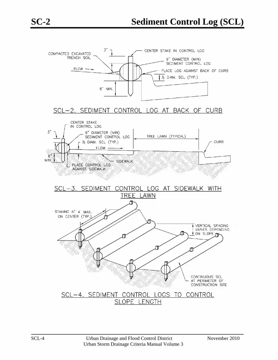
SC-2 Sediment Control Log (SCL)
SCL-4 Urban Drainage and Flood Control District November 2010
Urban Storm Drainage Criteria Manual Volume 3
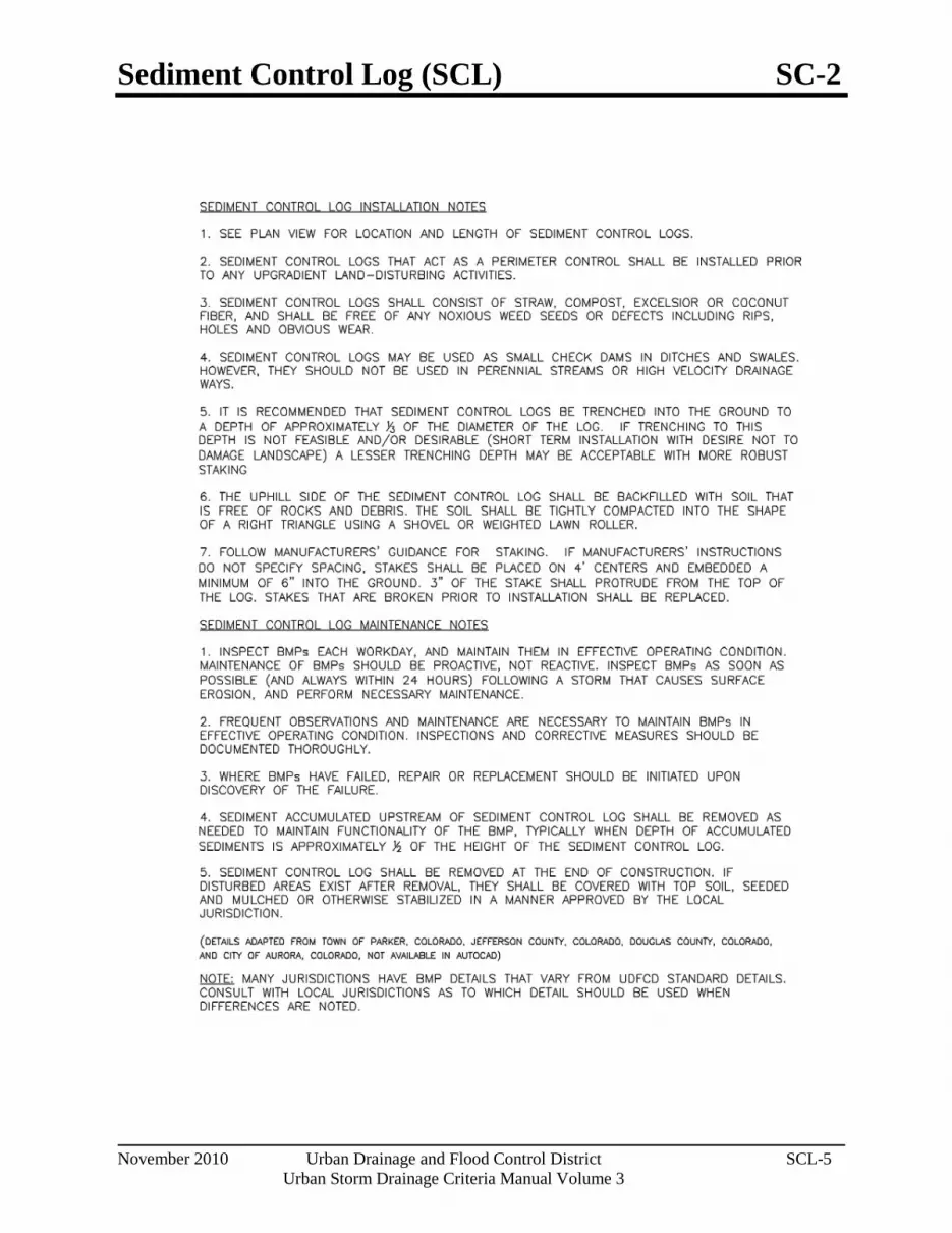
Sediment Control Log (SCL) SC-2
November 2010 Urban Drainage and Flood Control District SCL-5 Urban Storm Drainage Criteria Manual Volume 3

Straw Bale Barrier (SBB) SC-3
November 2010 Urban Drainage and Flood Control District SBB-1 Urban Storm Drainage Criteria Manual Volume 3
Photograph SBB-1. Straw bale barrier used for perimeter control. Photo courtesy of Tom Gore.
Description A straw bale barrier is a linear wall of straw bales designed to intercept sheet flow and trap sediment before runoff exits a disturbed area.
Appropriate Uses Appropriate uses of properly installed straw bale barriers may include:
As a perimeter control for a site or soil stockpile.
As a sediment control at the toe of an erodible slope.
Along the edge of a stream or drainage pathway to reduce sediment laden runoff from entering the waterway.
As part of an inlet protection design in sump conditions (See Inlet Protection BMP).
Do not use straw bale barriers in areas of concentrated flow or in areas where ponding is not desirable. Straw bales tend to degrade quickly, so they should generally not be used in areas where longer term disturbance is expected.
Due to a history of inappropriate placement, poor installation, and short effective lifespan, the use of straw bales is discouraged or prohibited by some communities.
Design and Installation The maximum recommended tributary drainage area per 100 lineal feet of straw bale barrier is 0.25 acres with a disturbed slope length of up to 150 feet and a tributary slope gradient no steeper than 3:1; longer and steeper slopes require additional measures. Design details with notes are provided in Detail SBB-1. To be effective, bales must be installed in accordance with the design details with proper trenching, staking, and binding. Jute and cotton string must not be used to bind the straw bale. The bales should be certified weed-free prior to use.
Maintenance and Removal Check bales for rotting and replace as necessary. Straw bales degrade, and rotting bales require replacement on a regular basis (as often as every three months) depending on environmental conditions. Check for undercutting, bypassed flows, and displacement. Repair by properly re-installing the straw bale barrier and repairing washouts around the bales. Remove sediment accumulated behind the bale when it reaches one-quarter of the bale height. Remove and properly dispose of the straw bale once the upstream area has been stabilized. Areas of disturbance beneath the bale should be seeded and mulched when the bale is removed.
Straw Bale Barrier Functions Erosion Control No Sediment Control Moderate Site/Material Management No

SC-3 Straw Bale Barrier (SBB)
SBB-2 Urban Drainage and Flood Control District November 2010
Urban Storm Drainage Criteria Manual Volume 3

Straw Bale Barrier (SBB) SC-3
November 2010 Urban Drainage and Flood Control District SBB-3 Urban Storm Drainage Criteria Manual Volume 3
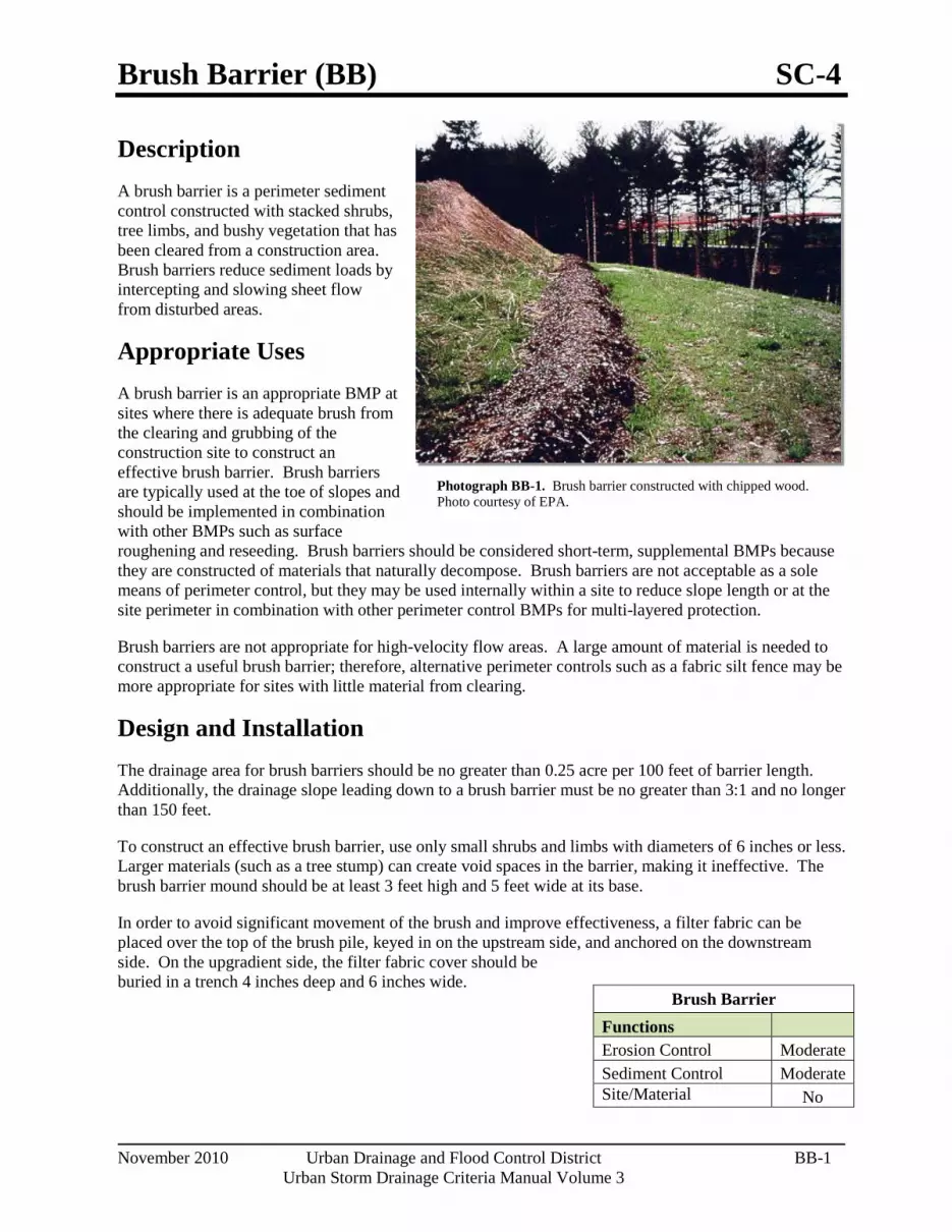
Brush Barrier (BB) SC-4
November 2010 Urban Drainage and Flood Control District BB-1 Urban Storm Drainage Criteria Manual Volume 3
Description A brush barrier is a perimeter sediment control constructed with stacked shrubs, tree limbs, and bushy vegetation that has been cleared from a construction area. Brush barriers reduce sediment loads by intercepting and slowing sheet flow from disturbed areas.
Appropriate Uses A brush barrier is an appropriate BMP at sites where there is adequate brush from the clearing and grubbing of the construction site to construct an effective brush barrier. Brush barriers are typically used at the toe of slopes and should be implemented in combination with other BMPs such as surface roughening and reseeding. Brush barriers should be considered short-term, supplemental BMPs because they are constructed of materials that naturally decompose. Brush barriers are not acceptable as a sole means of perimeter control, but they may be used internally within a site to reduce slope length or at the site perimeter in combination with other perimeter control BMPs for multi-layered protection.
Brush barriers are not appropriate for high-velocity flow areas. A large amount of material is needed to construct a useful brush barrier; therefore, alternative perimeter controls such as a fabric silt fence may be more appropriate for sites with little material from clearing.
Design and Installation The drainage area for brush barriers should be no greater than 0.25 acre per 100 feet of barrier length. Additionally, the drainage slope leading down to a brush barrier must be no greater than 3:1 and no longer than 150 feet.
To construct an effective brush barrier, use only small shrubs and limbs with diameters of 6 inches or less. Larger materials (such as a tree stump) can create void spaces in the barrier, making it ineffective. The brush barrier mound should be at least 3 feet high and 5 feet wide at its base.
In order to avoid significant movement of the brush and improve effectiveness, a filter fabric can be placed over the top of the brush pile, keyed in on the upstream side, and anchored on the downstream side. On the upgradient side, the filter fabric cover should be buried in a trench 4 inches deep and 6 inches wide.
Brush Barrier
Functions Erosion Control Moderate Sediment Control Moderate Site/Material
No
Photograph BB-1. Brush barrier constructed with chipped wood. Photo courtesy of EPA.

SC-4 Brush Barrier (BB)
BB-2 Urban Drainage and Flood Control District November 2010
Urban Storm Drainage Criteria Manual Volume 3
Maintenance and Removal Inspect the brush barrier for voids where concentrated flow or erosion is occurring. Voids in the brush barrier should be filled with additional brush. Accumulated sediment should be removed from the uphill side of the barrier when sediment height reaches one-third of the height of the barrier.
If filter fabric is used, inspect the filter fabric for damage; replace and properly secure it, as needed.
Once the upstream area has been vegetated or stabilized, the brush barrier should be removed and the underlying area revegetated.

Rock Sock (RS) SC-5
November 2010 Urban Drainage and Flood Control District RS-1 Urban Storm Drainage Criteria Manual Volume 3
Photograph RS-1. Rock socks placed at regular intervals in a curb line can help reduce sediment loading to storm sewer inlets. Rock socks can also be used as perimeter controls.
Description A rock sock is constructed of gravel that has been wrapped by wire mesh or a geotextile to form an elongated cylindrical filter. Rock socks are typically used either as a perimeter control or as part of inlet protection. When placed at angles in the curb line, rock socks are typically referred to as curb socks. Rock socks are intended to trap sediment from stormwater runoff that flows onto roadways as a result of construction activities.
Appropriate Uses Rock socks can be used at the perimeter of a disturbed area to control localized sediment loading. A benefit of rock socks as opposed to other perimeter controls is that they do not have to be trenched or staked into the ground; therefore, they are often used on roadway construction projects where paved surfaces are present.
Use rock socks in inlet protection applications when the construction of a roadway is substantially complete and the roadway has been directly connected to a receiving storm system.
Design and Installation When rock socks are used as perimeter controls, the maximum recommended tributary drainage area per 100 lineal feet of rock socks is approximately 0.25 acres with disturbed slope length of up to 150 feet and a tributary slope gradient no steeper than 3:1. A rock sock design detail and notes are provided in Detail RS-1. Also see the Inlet Protection Fact Sheet for design and installation guidance when rock socks are used for inlet protection and in the curb line.
When placed in the gutter adjacent to a curb, rock socks should protrude no more than two feet from the curb in order for traffic to pass safely. If located in a high traffic area, place construction markers to alert drivers and street maintenance workers of their presence.
Maintenance and Removal Rock socks are susceptible to displacement and breaking due to vehicle traffic. Inspect rock socks for damage and repair or replace as necessary. Remove sediment by sweeping or vacuuming as needed to maintain the functionality of the BMP, typically when sediment has accumulated behind the rock sock to one-half of the sock's height.
Once upstream stabilization is complete, rock socks and accumulated sediment should be removed and properly disposed.
Rock Sock Functions Erosion Control No Sediment Control Yes Site/Material Management No

SC-5 Rock Sock (RS)
RS-2 Urban Drainage and Flood Control District November 2010
Urban Storm Drainage Criteria Manual Volume 3

Rock Sock (RS) SC-5
November 2010 Urban Drainage and Flood Control District RS-3 Urban Storm Drainage Criteria Manual Volume 3

Inlet Protection (IP) SC-6
August 2013 Urban Drainage and Flood Control District IP-1 Urban Storm Drainage Criteria Manual Volume 3
Photograph IP-1. Inlet protection for a curb opening inlet.
Description Inlet protection consists of permeable barriers installed around an inlet to filter runoff and remove sediment prior to entering a storm drain inlet. Inlet protection can be constructed from rock socks, sediment control logs, silt fence, block and rock socks, or other materials approved by the local jurisdiction. Area inlets can also be protected by over-excavating around the inlet to form a sediment trap.
Appropriate Uses Install protection at storm sewer inlets that are operable during construction. Consider the potential for tracked-out sediment or temporary stockpile areas to contribute sediment to inlets when determining which inlets must be protected. This may include inlets in the general proximity of the construction area, not limited to downgradient inlets. Inlet protection is not a stand-alone BMP and should be used in conjunction with other upgradient BMPs.
Design and Installation To function effectively, inlet protection measures must be installed to ensure that flows do not bypass the inlet protection and enter the storm drain without treatment. However, designs must also enable the inlet to function without completely blocking flows into the inlet in a manner that causes localized flooding. When selecting the type of inlet protection, consider factors such as type of inlet (e.g., curb or area, sump or on-grade conditions), traffic, anticipated flows, ability to secure the BMP properly, safety and other site-specific conditions. For example, block and rock socks will be better suited to a curb and gutter along a roadway, as opposed to silt fence or sediment control logs, which cannot be properly secured in a curb and gutter setting, but are effective area inlet protection measures.
Several inlet protection designs are provided in the Design Details. Additionally, a variety of proprietary products are available for inlet protection that may be approved for use by local governments. If proprietary products are used, design details and installation procedures from the manufacturer must be followed. Regardless of the type of inlet protection selected, inlet protection is most effective when combined with other BMPs such as curb socks and check dams. Inlet protection is often the last barrier before runoff enters the storm sewer or receiving water.
Design details with notes are provided for these forms of inlet protection:
IP-1. Block and Rock Sock Inlet Protection for Sump or On-grade Inlets
IP-2. Curb (Rock) Socks Upstream of Inlet Protection, On-grade Inlets
Inlet Protection (various forms)
Functions Erosion Control No Sediment Control Yes Site/Material Management No

SC-6 Inlet Protection (IP)
IP-2 Urban Drainage and Flood Control District August 2013 Urban Storm Drainage Criteria Manual Volume 3
IP-3. Rock Sock Inlet Protection for Sump/Area Inlet
IP-4. Silt Fence Inlet Protection for Sump/Area Inlet
IP-5. Over-excavation Inlet Protection
IP-6. Straw Bale Inlet Protection for Sump/Area Inlet
CIP-1. Culvert Inlet Protection
Propriety inlet protection devices should be installed in accordance with manufacturer specifications.
More information is provided below on selecting inlet protection for sump and on-grade locations.
Inlets Located in a Sump
When applying inlet protection in sump conditions, it is important that the inlet continue to function during larger runoff events. For curb inlets, the maximum height of the protective barrier should be lower than the top of the curb opening to allow overflow into the inlet during larger storms without excessive localized flooding. If the inlet protection height is greater than the curb elevation, particularly if the filter becomes clogged with sediment, runoff will not enter the inlet and may bypass it, possibly causing localized flooding, public safety issues, and downstream erosion and damage from bypassed flows.
Area inlets located in a sump setting can be protected through the use of silt fence, concrete block and rock socks (on paved surfaces), sediment control logs/straw wattles embedded in the adjacent soil and stacked around the area inlet (on pervious surfaces), over-excavation around the inlet, and proprietary products providing equivalent functions.
Inlets Located on a Slope
For curb and gutter inlets on paved sloping streets, block and rock sock inlet protection is recommended in conjunction with curb socks in the gutter leading to the inlet. For inlets located along unpaved roads, also see the Check Dam Fact Sheet.
Maintenance and Removal Inspect inlet protection frequently. Inspection and maintenance guidance includes:
Inspect for tears that can result in sediment directly entering the inlet, as well as result in the contents of the BMP (e.g., gravel) washing into the inlet.
Check for improper installation resulting in untreated flows bypassing the BMP and directly entering the inlet or bypassing to an unprotected downstream inlet. For example, silt fence that has not been properly trenched around the inlet can result in flows under the silt fence and directly into the inlet.
Look for displaced BMPs that are no longer protecting the inlet. Displacement may occur following larger storm events that wash away or reposition the inlet protection. Traffic or equipment may also crush or displace the BMP.
Monitor sediment accumulation upgradient of the inlet protection.

Inlet Protection (IP) SC-6
August 2013 Urban Drainage and Flood Control District IP-3 Urban Storm Drainage Criteria Manual Volume 3
Remove sediment accumulation from the area upstream of the inlet protection, as needed to maintain BMP effectiveness, typically when it reaches no more than half the storage capacity of the inlet protection. For silt fence, remove sediment when it accumulates to a depth of no more than 6 inches. Remove sediment accumulation from the area upstream of the inlet protection as needed to maintain the functionality of the BMP.
Propriety inlet protection devices should be inspected and maintained in accordance with manufacturer specifications. If proprietary inlet insert devices are used, sediment should be removed in a timely manner to prevent devices from breaking and spilling sediment into the storm drain.
Inlet protection must be removed and properly disposed of when the drainage area for the inlet has reached final stabilization.

SC-6 Inlet Protection (IP)
IP-4 Urban Drainage and Flood Control District August 2013 Urban Storm Drainage Criteria Manual Volume 3

Inlet Protection (IP) SC-6
August 2013 Urban Drainage and Flood Control District IP-5 Urban Storm Drainage Criteria Manual Volume 3
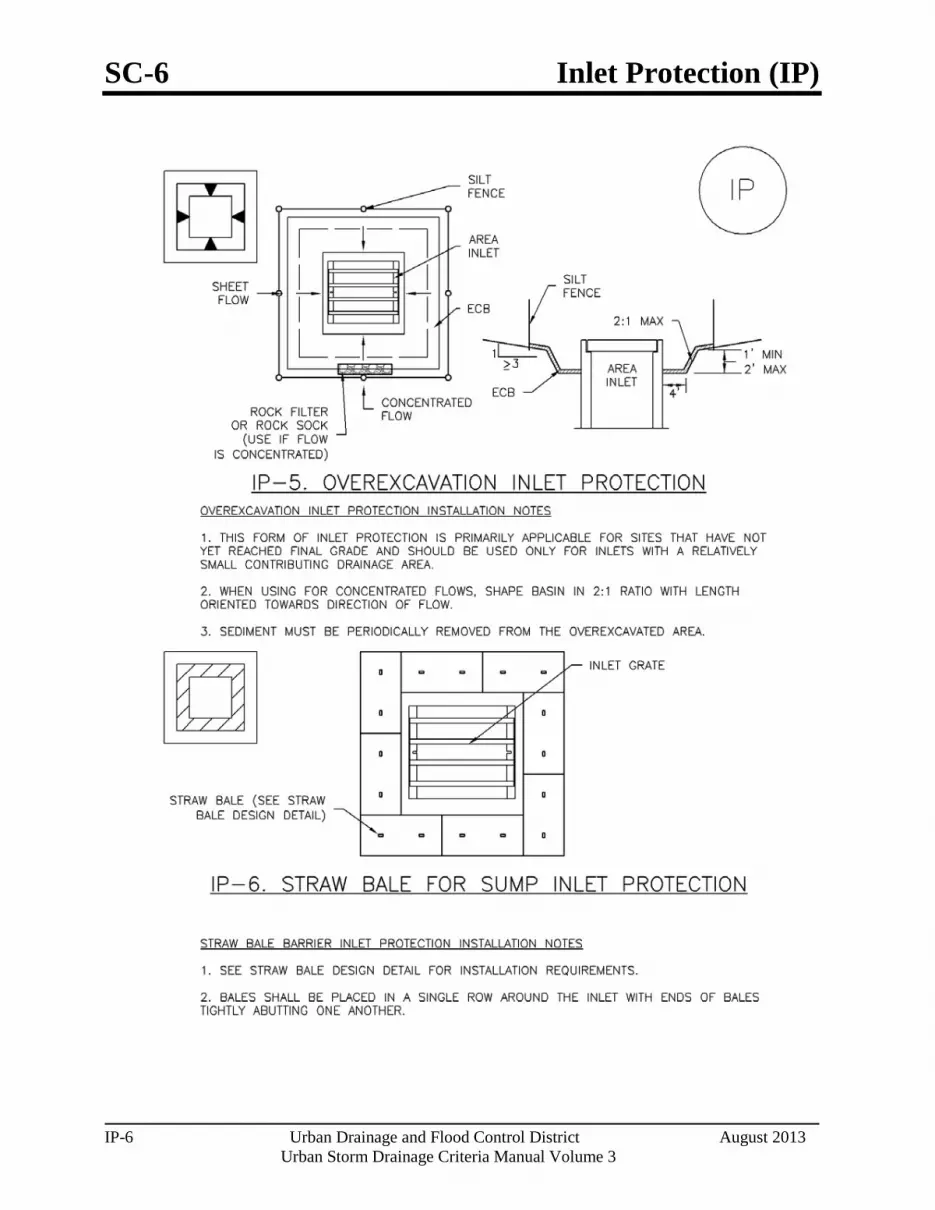
SC-6 Inlet Protection (IP)
IP-6 Urban Drainage and Flood Control District August 2013 Urban Storm Drainage Criteria Manual Volume 3

Inlet Protection (IP) SC-6
August 2013 Urban Drainage and Flood Control District IP-7 Urban Storm Drainage Criteria Manual Volume 3

SC-6 Inlet Protection (IP)
IP-8 Urban Drainage and Flood Control District August 2013 Urban Storm Drainage Criteria Manual Volume 3

Sediment Basin (SB) SC-7
August 2013 Urban Drainage and Flood Control District SB-1 Urban Storm Drainage Criteria Manual Volume 3
Photograph SB-1. Sediment basin at the toe of a slope. Photo courtesy of WWE.
Description A sediment basin is a temporary pond built on a construction site to capture eroded or disturbed soil transported in storm runoff prior to discharge from the site. Sediment basins are designed to capture site runoff and slowly release it to allow time for settling of sediment prior to discharge. Sediment basins are often constructed in locations that will later be modified to serve as post-construction stormwater basins.
Appropriate Uses Most large construction sites (typically greater than 2 acres) will require one or more sediment basins for effective management of construction site runoff. On linear construction projects, sediment basins may be impractical; instead, sediment traps or other combinations of BMPs may be more appropriate.
Sediment basins should not be used as stand-alone sediment controls. Erosion and other sediment controls should also be implemented upstream.
When feasible, the sediment basin should be installed in the same location where a permanent post-construction detention pond will be located.
Design and Installation The design procedure for a sediment basin includes these steps:
Basin Storage Volume: Provide a storage volume of at least 3,600 cubic feet per acre of drainage area. To the extent practical, undisturbed and/or off-site areas should be diverted around sediment basins to prevent “clean” runoff from mixing with runoff from disturbed areas. For undisturbed areas (both on-site and off-site) that cannot be diverted around the sediment basin, provide a minimum of 500 ft3/acre of storage for undeveloped (but stable) off-site areas in addition to the 3,600 ft3/acre for disturbed areas. For stable, developed areas that cannot be diverted around the sediment basin, storage volume requirements are summarized in Table SB-1.
Basin Geometry: Design basin with a minimum length-to-width ratio of 2:1 (L:W). If this cannot be achieved because of site space constraints, baffling may be required to extend the effective distance between the inflow point(s) and the outlet to minimize short-circuiting.
Dam Embankment: It is recommended that embankment slopes be 4:1 (H:V) or flatter and no steeper than 3:1 (H:V) in any location.
Sediment Basins
Functions Erosion Control No Sediment Control Yes Site/Material Management No

SC-7 Sediment Basin (SB)
SB-2 Urban Drainage and Flood Control District August 2013
Urban Storm Drainage Criteria Manual Volume 3
Inflow Structure: For concentrated flow entering the basin, provide energy dissipation at the point of inflow.
Table SB-1. Additional Volume Requirements for Undisturbed and Developed Tributary Areas Draining through Sediment Basins
Imperviousness (%) Additional Storage Volume (ft3)
Per Acre of Tributary Area Undeveloped 500
10 800 20 1230 30 1600 40 2030 50 2470 60 2980 70 3560 80 4360 90 5300 100 6460
Outlet Works: The outlet pipe shall extend through the embankment at a minimum slope of 0.5 percent. Outlet works can be designed using one of the following approaches:
o Riser Pipe (Simplified Detail): Detail SB-1 provides a simplified design for basins treating no more than 15 acres.
o Orifice Plate or Riser Pipe: Follow the design criteria for Full Spectrum Detention outlets in the EDB Fact Sheet provided in Chapter 4 of this manual for sizing of outlet perforations with an emptying time of approximately 72 hours. In lieu of the trash rack, pack uniformly sized 1½ - to 2-inch gravel in front of the plate or surrounding the riser pipe. This gravel will need to be cleaned out frequently during the construction period as sediment accumulates within it. The gravel pack will need to be removed and disposed of following construction to reclaim the basin for use as a permanent detention facility. If the basin will be used as a permanent extended detention basin for the site, a trash rack will need to be installed once contributing drainage areas have been stabilized and the gravel pack and accumulated sediment have been removed.
o Floating Skimmer: If a floating skimmer is used, install it using manufacturer’s recommendations. Illustration SB-1 provides an illustration of a Faircloth Skimmer Floating Outlet™, one of the more commonly used floating skimmer outlets. A skimmer should be designed to release the design volume in no less than 48 hours. The use of a floating skimmer outlet can increase the sediment capture efficiency of a basin significantly. A floating outlet continually decants cleanest water off the surface of the pond and releases cleaner water than would discharge from a perforated riser pipe or plate.

Sediment Basin (SB) SC-7
August 2013 Urban Drainage and Flood Control District SB-3 Urban Storm Drainage Criteria Manual Volume 3
Illustration SB-1. Outlet structure for a temporary sediment basin - Faircloth Skimmer Floating Outlet. Illustration courtesy of J. W. Faircloth & Sons, Inc., FairclothSkimmer.com.
Outlet Protection and Spillway: Consider all flow paths for runoff leaving the basin, including protection at the typical point of discharge as well as overtopping.
o Outlet Protection: Outlet protection should be provided where the velocity of flow will exceed the maximum permissible velocity of the material of the waterway into which discharge occurs. This may require the use of a riprap apron at the outlet location and/or other measures to keep the waterway from eroding.
o Emergency Spillway: Provide a stabilized emergency overflow spillway for rainstorms that exceed the capacity of the sediment basin volume and its outlet. Protect basin embankments from erosion and overtopping. If the sediment basin will be converted to a permanent detention basin, design and construct the emergency spillway(s) as required for the permanent facility. If the sediment basin will not become a permanent detention basin, it may be possible to substitute a heavy polyvinyl membrane or properly bedded rock cover to line the spillway and downstream embankment, depending on the height, slope, and width of the embankments.
SC-7 Sediment Basin (SB)
SB-4 Urban Drainage and Flood Control District August 2013
Urban Storm Drainage Criteria Manual Volume 3
Maintenance and Removal Maintenance activities include the following:
• Dredge sediment from the basin, as needed to maintain BMP effectiveness, typically when the design storage volume is no more than one-third filled with sediment.
• Inspect the sediment basin embankments for stability and seepage.
• Inspect the inlet and outlet of the basin, repair damage, and remove debris. Remove, clean and replace the gravel around the outlet on a regular basis to remove the accumulated sediment within it and keep the outlet functioning.
• Be aware that removal of a sediment basin may require dewatering and associated permit requirements.
• Do not remove a sediment basin until the upstream area has been stabilized with vegetation.
Final disposition of the sediment basin depends on whether the basin will be converted to a permanent post-construction stormwater basin or whether the basin area will be returned to grade. For basins being converted to permanent detention basins, remove accumulated sediment and reconfigure the basin and outlet to meet the requirements of the final design for the detention facility. If the sediment basin is not to be used as a permanent detention facility, fill the excavated area with soil and stabilize with vegetation.

Sediment Basin (SB) SC-7
August 2013 Urban Drainage and Flood Control District SB-5 Urban Storm Drainage Criteria Manual Volume 3

SC-7 Sediment Basin (SB)
SB-6 Urban Drainage and Flood Control District August 2013
Urban Storm Drainage Criteria Manual Volume 3

Sediment Basin (SB) SC-7
August 2013 Urban Drainage and Flood Control District SB-7 Urban Storm Drainage Criteria Manual Volume 3

Sediment Trap (ST) SC-8
November 2010 Urban Drainage and Flood Control District ST-1 Urban Storm Drainage Criteria Manual Volume 3
Photograph ST-1. Sediment traps are used to collect sediment-laden runoff from disturbed area. Photo courtesy of EPA Menu of BMPs.
Description Sediment traps are formed by excavating an area or by placing an earthen embankment across a low area or drainage swale. Sediment traps are designed to capture drainage from disturbed areas less than one acre and allow settling of sediment.
Appropriate Uses Sediment traps can be used in combination with other layers of erosion and sediment controls to trap sediment from small drainage areas (less than one acre) or areas with localized high sediment loading. For example, sediment traps are often provided in conjunction with vehicle tracking controls and wheel wash facilities.
Design and Installation A sediment trap consists of a small excavated basin with an earthen berm and a riprap outlet. The berm of the sediment trap may be constructed from the excavated material and must be compacted to 95 percent of the maximum density in accordance with ASTM D698. An overflow outlet must be provided at an elevation at least 6 inches below the top of the berm. See Detail ST-1 for additional design and installation information.
Maintenance and Removal Inspect the sediment trap embankments for stability and seepage.
Remove accumulated sediment as needed to maintain the effectiveness of the sediment trap, typically when the sediment depth is approximately one-half the height of the outflow embankment.
Inspect the outlet for debris and damage. Repair damage to the outlet, and remove all obstructions.
A sediment trap should not be removed until the upstream area is sufficiently stabilized. Upon removal of the trap, the disturbed area should be covered with topsoil and stabilized.
Sediment Trap
Functions Erosion Control No Sediment Control Yes Site/Material Management No

SC-8 Sediment Trap (ST)
ST-2 Urban Drainage and Flood Control District November 2010
Urban Storm Drainage Criteria Manual Volume 3

Sediment Trap (ST) SC-8
November 2010 Urban Drainage and Flood Control District ST-3 Urban Storm Drainage Criteria Manual Volume 3

Vegetated Buffers (VB) SC-9
November 2010 Urban Drainage and Flood Control District VB-1 Urban Storm Drainage Criteria Manual Volume 3
Photograph VB-1. A vegetated buffer is maintained between the area of active construction and the drainage swale. Photo courtesy of WWE.
Description Buffer strips of preserved natural vegetation or grass help protect waterways and wetlands from land disturbing activities. Vegetated buffers improve stormwater runoff quality by straining sediment, promoting infiltration, and slowing runoff velocities.
Appropriate Uses Vegetated buffers can be used to separate land disturbing activities and natural surface waters or conveyances. In many jurisdictions, local governments require some type of setback from natural waterways. Concentrated flow should not be directed through a buffer; instead, runoff should be in the form of sheet flow. Vegetated buffers are typically used in combination with other perimeter control BMPs such as sediment control logs or silt fence for multi-layered protection.
Design and Installation Minimum buffer widths may vary based on local regulations. Clearly delineate the boundary of the natural buffer area using construction fencing, silt fence, or a comparable technique. In areas that have been cleared and graded, vegetated buffers such as sod can also be installed to create or restore a vegetated buffer around the perimeter of the site.
Maintenance and Removal Inspect buffer areas for signs of erosion such as gullies or rills. Stabilize eroding areas, as needed. If erosion is due to concentrated flow conditions, it may be necessary to install a level spreader or other technique to restore sheet flow conditions. Inspect perimeter controls delineating the vegetative buffer and repair or replace as needed.
Vegetated Buffers
Functions Erosion Control Moderate Sediment Control Yes Site/Material Management Yes
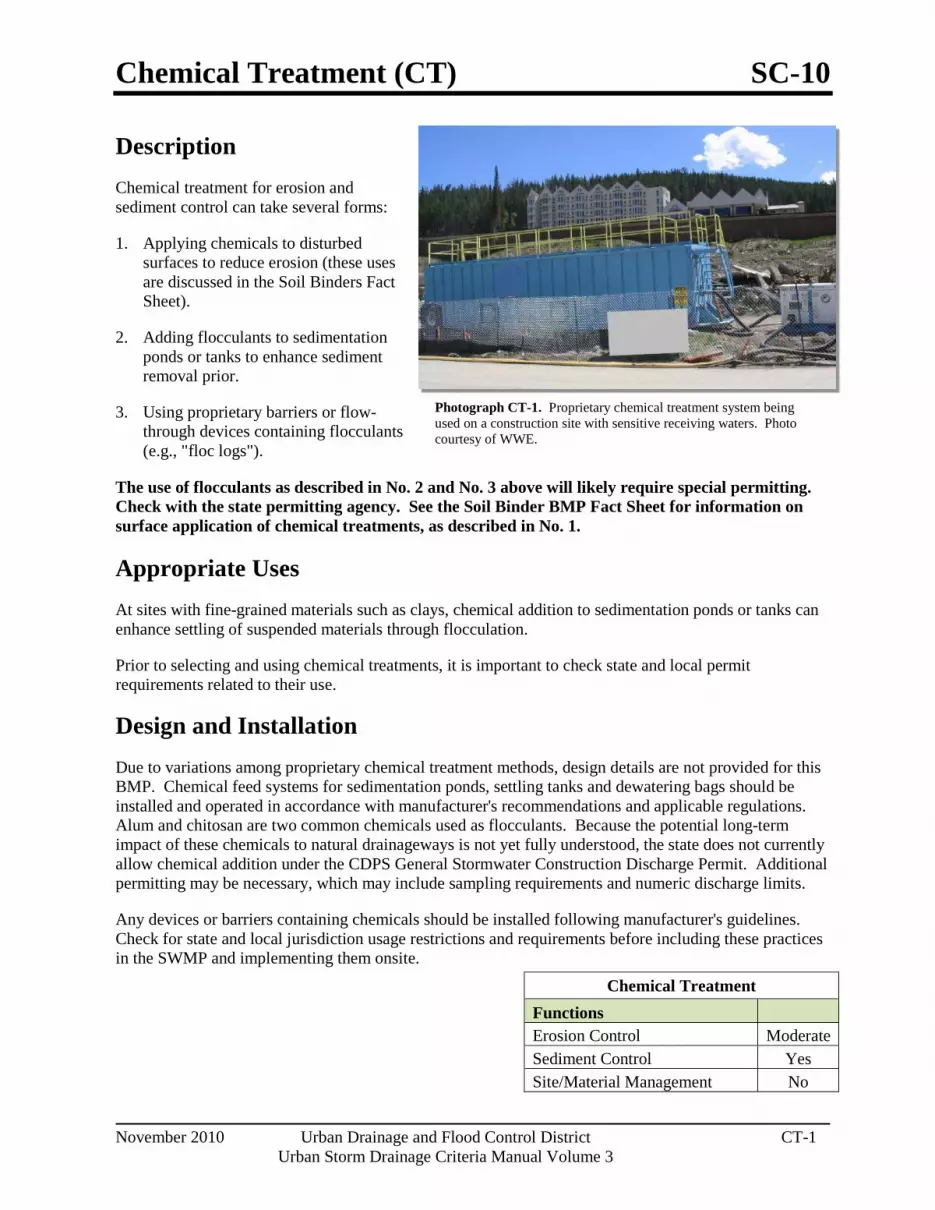
Chemical Treatment (CT) SC-10
November 2010 Urban Drainage and Flood Control District CT-1 Urban Storm Drainage Criteria Manual Volume 3
Photograph CT-1. Proprietary chemical treatment system being used on a construction site with sensitive receiving waters. Photo courtesy of WWE.
Description Chemical treatment for erosion and sediment control can take several forms:
1. Applying chemicals to disturbed surfaces to reduce erosion (these uses are discussed in the Soil Binders Fact Sheet).
2. Adding flocculants to sedimentation ponds or tanks to enhance sediment removal prior.
3. Using proprietary barriers or flow-through devices containing flocculants (e.g., "floc logs").
The use of flocculants as described in No. 2 and No. 3 above will likely require special permitting. Check with the state permitting agency. See the Soil Binder BMP Fact Sheet for information on surface application of chemical treatments, as described in No. 1.
Appropriate Uses At sites with fine-grained materials such as clays, chemical addition to sedimentation ponds or tanks can enhance settling of suspended materials through flocculation.
Prior to selecting and using chemical treatments, it is important to check state and local permit requirements related to their use.
Design and Installation Due to variations among proprietary chemical treatment methods, design details are not provided for this BMP. Chemical feed systems for sedimentation ponds, settling tanks and dewatering bags should be installed and operated in accordance with manufacturer's recommendations and applicable regulations. Alum and chitosan are two common chemicals used as flocculants. Because the potential long-term impact of these chemicals to natural drainageways is not yet fully understood, the state does not currently allow chemical addition under the CDPS General Stormwater Construction Discharge Permit. Additional permitting may be necessary, which may include sampling requirements and numeric discharge limits.
Any devices or barriers containing chemicals should be installed following manufacturer's guidelines. Check for state and local jurisdiction usage restrictions and requirements before including these practices in the SWMP and implementing them onsite.
Chemical Treatment Functions Erosion Control Moderate Sediment Control Yes Site/Material Management No
SC-10 Chemical Treatment (CT)
CT-2 Urban Drainage and Flood Control District November 2010
Urban Storm Drainage Criteria Manual Volume 3
Maintenance and Removal Chemical feed systems for sedimentation ponds or tanks should be maintained in accordance with manufacturer's recommendations and removed when the systems are no longer being used. Accumulated sediment should be dried and disposed of either at a landfill or in accordance with applicable regulations.
Barriers and devices containing chemicals should be removed and replaced when tears or other damage to the devices are observed. These barriers should be removed and properly disposed of when the site has been stabilized.

Construction Phasing/Sequencing (CP) SM-1
November 2010 Urban Drainage and Flood Control District CP-1 Urban Storm Drainage Criteria Manual Volume 3
Photograph CP-1. Construction phasing to avoid disturbing the entire area at one time. Photo courtesy of WWE.
Description Effective construction site management to minimize erosion and sediment transport includes attention to construction phasing, scheduling, and sequencing of land disturbing activities. On most construction projects, erosion and sediment controls will need to be adjusted as the project progresses and should be documented in the SWMP.
Construction phasing refers to disturbing only part of a site at a time to limit the potential for erosion from dormant parts of a site. Grading activities and construction are completed and soils are effectively stabilized on one part of a site before grading and construction begins on another portion of the site.
Construction sequencing or scheduling refers to a specified work schedule that coordinates the timing of land disturbing activities and the installation of erosion and sediment control practices.
Appropriate Uses All construction projects can benefit from upfront planning to phase and sequence construction activities to minimize the extent and duration of disturbance. Larger projects and linear construction projects may benefit most from construction sequencing or phasing, but even small projects can benefit from construction sequencing that minimizes the duration of disturbance.
Typically, erosion and sediment controls needed at a site will change as a site progresses through the major phases of construction. Erosion and sediment control practices corresponding to each phase of construction must be documented in the SWMP.
Design and Installation BMPs appropriate to the major phases of development should be identified on construction drawings. In some cases, it will be necessary to provide several drawings showing construction-phase BMPs placed according to stages of development (e.g., clearing and grading, utility installation, active construction, final stabilization). Some municipalities in the Denver area set maximum sizes for disturbed area associated with phases of a construction project. Additionally, requirements for phased construction drawings vary among local governments within the UDFCD boundary. Some local governments require separate erosion and sediment control drawings for initial BMPs, interim conditions (in active construction), and final stabilization.
Construction Scheduling Functions Erosion Control Moderate Sediment Control Moderate Site/Material Management Yes

SM-1 Construction Phasing/Sequencing (CP)
CP-2 Urban Drainage and Flood Control District November 2010
Urban Storm Drainage Criteria Manual Volume 3
Typical construction phasing BMPs include:
Limit the amount of disturbed area at any given time on a site to the extent practical. For example, a 100-acre subdivision might be constructed in five phases of 20 acres each.
If there is carryover of stockpiled material from one phase to the next, position carryover material in a location easily accessible for the pending phase that will not require disturbance of stabilized areas to access the stockpile. Particularly with regard to efforts to balance cut and fill at a site, careful planning for location of stockpiles is important.
Typical construction sequencing BMPs include:
Sequence construction activities to minimize duration of soil disturbance and exposure. For example, when multiple utilities will occupy the same trench, schedule installation so that the trench does not have to be closed and opened multiple times.
Schedule site stabilization activities (e.g., landscaping, seeding and mulching, installation of erosion control blankets) as soon as feasible following grading.
Install initial erosion and sediment control practices before construction begins. Promptly install additional BMPs for inlet protection, stabilization, etc., as construction activities are completed.
Table CP-1 provides typical sequencing of construction activities and associated BMPs.
Maintenance and Removal When the construction schedule is altered, erosion and sediment control measures in the SWMP and construction drawings should be appropriately adjusted to reflect actual "on the ground" conditions at the construction site. Be aware that changes in construction schedules can have significant implications for site stabilization, particularly with regard to establishment of vegetative cover.

Construction Phasing/Sequencing (CP) SM-1
November 2010 Urban Drainage and Flood Control District CP-3 Urban Storm Drainage Criteria Manual Volume 3
Table CP-1. Typical Phased BMP Installation for Construction Projects
Project Phase BMPs
Pre-disturbance, Site Access
Install sediment controls downgradient of access point (on paved streets this may consist of inlet protection).
Establish vehicle tracking control at entrances to paved streets. Fence as needed.
Use construction fencing to define the boundaries of the project and limit access to areas of the site that are not to be disturbed.
Note: it may be necessary to protect inlets in the general vicinity of the site, even if not downgradient, if there is a possibility that sediment tracked from the site could contribute to the inlets.
Site Clearing and Grubbing
Install perimeter controls as needed on downgradient perimeter of site (silt fence, wattles, etc).
Limit disturbance to those areas planned for disturbance and protect undisturbed areas within the site (construction fence, flagging, etc).
Preserve vegetative buffer at site perimeter.
Create stabilized staging area.
Locate portable toilets on flat surfaces away from drainage paths. Stake in areas susceptible to high winds.
Construct concrete washout area and provide signage.
Establish waste disposal areas.
Install sediment basins.
Create dirt perimeter berms and/or brush barriers during grubbing and clearing.
Separate and stockpile topsoil, leave roughened and/or cover.
Protect stockpiles with perimeter control BMPs. Stockpiles should be located away from drainage paths and should be accessed from the upgradient side so that perimeter controls can remain in place on the downgradient side. Use erosion control blankets, temporary seeding, and/or mulch for stockpiles that will be inactive for an extended period.
Leave disturbed area of site in a roughened condition to limit erosion. Consider temporary revegetation for areas of the site that have been disturbed but that will be inactive for an extended period.
Water to minimize dust but not to the point that watering creates runoff.

SM-1 Construction Phasing/Sequencing (CP)
CP-4 Urban Drainage and Flood Control District November 2010
Urban Storm Drainage Criteria Manual Volume 3
Project Phase BMPs
Utility And Infrastructure Installation
In Addition to the Above BMPs:
Close trench as soon as possible (generally at the end of the day).
Use rough-cut street control or apply road base for streets that will not be promptly paved.
Provide inlet protection as streets are paved and inlets are constructed.
Protect and repair BMPs, as necessary.
Perform street sweeping as needed.
Building Construction
In Addition to the Above BMPs:
Implement materials management and good housekeeping practices for home building activities.
Use perimeter controls for temporary stockpiles from foundation excavations.
For lots adjacent to streets, lot-line perimeter controls may be necessary at the back of curb.
Final Grading
In Addition to the Above BMPs:
Remove excess or waste materials.
Remove stored materials.
Final Stabilization
In Addition to the Above BMPs:
Seed and mulch/tackify.
Seed and install blankets on steep slopes.
Remove all temporary BMPs when site has reached final stabilization.

Protection of Existing Vegetation (PV) SM-2
November 2010 Urban Drainage and Flood Control District PV-1 Urban Storm Drainage Criteria Manual Volume 3
Photograph PV-1. Protection of existing vegetation and a sensitive area. Photo courtesy of CDOT.
Description Protection of existing vegetation on a construction site can be accomplished through installation of a construction fence around the area requiring protection. In cases where upgradient areas are disturbed, it may also be necessary to install perimeter controls to minimize sediment loading to sensitive areas such as wetlands. Existing vegetation may be designated for protection to maintain a stable surface cover as part of construction phasing, or vegetation may be protected in areas designated to remain in natural condition under post-development conditions (e.g., wetlands, mature trees, riparian areas, open space).
Appropriate Uses Existing vegetation should be preserved for the maximum practical duration on a construction site through the use of effective construction phasing. Preserving vegetation helps to minimize erosion and can reduce revegetation costs following construction.
Protection of wetland areas is required under the Clean Water Act, unless a permit has been obtained from the U.S. Army Corps of Engineers (USACE) allowing impacts in limited areas.
If trees are to be protected as part of post-development landscaping, care must be taken to avoid several types of damage, some of which may not be apparent at the time of injury. Potential sources of injury include soil compaction during grading or due to construction traffic, direct equipment-related injury such as bark removal, branch breakage, surface grading and trenching, and soil cut and fill. In order to minimize injuries that may lead to immediate or later death of the tree, tree protection zones should be developed during site design, implemented at the beginning of a construction project, as well as continued during active construction.
Design and Installation
General
Once an area has been designated as a preservation area, there should be no construction activity allowed within a set distance of the area. Clearly mark the area with construction fencing. Do not allow stockpiles, equipment, trailers or parking within the protected area. Guidelines to protect various types of existing vegetation follow.
Protection of Existing Vegetation Functions Erosion Control Yes Sediment Control Moderate Site/Material Management Yes
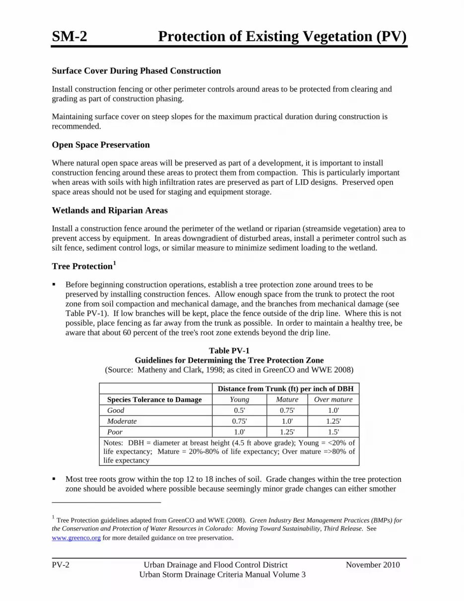
SM-2 Protection of Existing Vegetation (PV)
PV-2 Urban Drainage and Flood Control District November 2010
Urban Storm Drainage Criteria Manual Volume 3
Surface Cover During Phased Construction
Install construction fencing or other perimeter controls around areas to be protected from clearing and grading as part of construction phasing.
Maintaining surface cover on steep slopes for the maximum practical duration during construction is recommended.
Open Space Preservation
Where natural open space areas will be preserved as part of a development, it is important to install construction fencing around these areas to protect them from compaction. This is particularly important when areas with soils with high infiltration rates are preserved as part of LID designs. Preserved open space areas should not be used for staging and equipment storage.
Wetlands and Riparian Areas
Install a construction fence around the perimeter of the wetland or riparian (streamside vegetation) area to prevent access by equipment. In areas downgradient of disturbed areas, install a perimeter control such as silt fence, sediment control logs, or similar measure to minimize sediment loading to the wetland.
Tree Protection1
Before beginning construction operations, establish a tree protection zone around trees to be preserved by installing construction fences. Allow enough space from the trunk to protect the root zone from soil compaction and mechanical damage, and the branches from mechanical damage (see Table PV-1). If low branches will be kept, place the fence outside of the drip line. Where this is not possible, place fencing as far away from the trunk as possible. In order to maintain a healthy tree, be aware that about 60 percent of the tree's root zone extends beyond the drip line.
Table PV-1 Guidelines for Determining the Tree Protection Zone
(Source: Matheny and Clark, 1998; as cited in GreenCO and WWE 2008)
Distance from Trunk (ft) per inch of DBH Species Tolerance to Damage Young Mature Over mature Good 0.5' 0.75' 1.0' Moderate 0.75' 1.0' 1.25' Poor 1.0' 1.25' 1.5' Notes: DBH = diameter at breast height (4.5 ft above grade); Young = <20% of life expectancy; Mature = 20%-80% of life expectancy; Over mature =>80% of life expectancy
Most tree roots grow within the top 12 to 18 inches of soil. Grade changes within the tree protection zone should be avoided where possible because seemingly minor grade changes can either smother
1 Tree Protection guidelines adapted from GreenCO and WWE (2008). Green Industry Best Management Practices (BMPs) for the Conservation and Protection of Water Resources in Colorado: Moving Toward Sustainability, Third Release. See www.greenco.org for more detailed guidance on tree preservation.
Protection of Existing Vegetation (PV) SM-2
November 2010 Urban Drainage and Flood Control District PV-3 Urban Storm Drainage Criteria Manual Volume 3
roots (in fill situations) or damage roots (in cut situations). Consider small walls where needed to avoid grade changes in the tree protection zone.
Place and maintain a layer of mulch 4 to 6-inch thick from the tree trunk to the fencing, keeping a 6-inch space between the mulch and the trunk. Mulch helps to preserve moisture and decrease soil compaction if construction traffic is unavoidable. When planting operations are completed, the mulch may be reused throughout planting areas.
Limit access, if needed at all, and appoint one route as the main entrance and exit to the tree protection zone. Within the tree protection zone, do not allow any equipment to be stored, chemicals to be dumped, or construction activities to take place except fine grading, irrigation system installation, and planting operations. These activities should be conducted in consultation with a landscaping professional, following Green Industry BMPs.
Be aware that soil compaction can cause extreme damage to tree health that may appear gradually over a period of years. Soil compaction is easier to prevent than repair.
Maintenance and Removal Repair or replace damaged or displaced fencing or other protective barriers around the vegetated area.
If damage occurs to a tree, consult an arborist for guidance on how to care for the tree. If a tree in a designated preservation area is damaged beyond repair, remove and replace with a 2-inch diameter tree of the same or similar species.
Construction equipment must not enter a wetland area, except as permitted by the U.S. Army Corps of Engineers (USACE). Inadvertent placement of fill in a wetland is a 404 permit violation and will require notification of the USACE.
If damage to vegetation occurs in a protected area, reseed the area with the same or similar species, following the recommendations in the USDCM Revegetation chapter.

Construction Fence (CF) SM-3
November 2010 Urban Drainage and Flood Control District CF-1 Urban Storm Drainage Criteria Manual Volume 3
Photograph CF-1. A construction fence helps delineate areas where existing vegetation is being protected. Photo courtesy of Douglas County.
Description A construction fence restricts site access to designated entrances and exits, delineates construction site boundaries, and keeps construction out of sensitive areas such as natural areas to be preserved as open space, wetlands and riparian areas.
Appropriate Uses A construction fence can be used to delineate the site perimeter and locations within the site where access is restricted to protect natural resources such as wetlands, waterbodies, trees, and other natural areas of the site that should not be disturbed.
If natural resource protection is an objective, then the construction fencing should be used in combination with other perimeter control BMPs such as silt fence, sediment control logs or similar measures.
Design and Installation Construction fencing may be chain link or plastic mesh and should be installed following manufacturer’s recommendations. See Detail CF-1 for typical installations.
Do not place construction fencing in areas within work limits of machinery.
Maintenance and Removal Inspect fences for damage; repair or replace as necessary.
Fencing should be tight and any areas with slumping or fallen posts should be reinstalled.
Fencing should be removed once construction is complete.
Construction Fence
Functions Erosion Control No Sediment Control No Site/Material Management Yes

SM-3 Construction Fence (CF)
CF-2 Urban Drainage and Flood Control District November 2010
Urban Storm Drainage Criteria Manual Volume 3

Construction Fence (CF) SM-3
November 2010 Urban Drainage and Flood Control District CF-3 Urban Storm Drainage Criteria Manual Volume 3
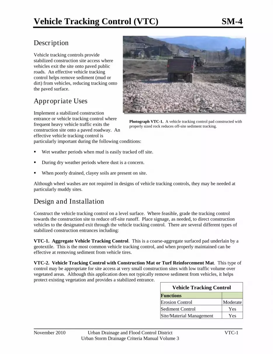
Vehicle Tracking Control (VTC) SM-4
November 2010 Urban Drainage and Flood Control District VTC-1 Urban Storm Drainage Criteria Manual Volume 3
Photograph VTC-1. A vehicle tracking control pad constructed with properly sized rock reduces off-site sediment tracking.
Descr iption Vehicle tracking controls provide stabilized construction site access where vehicles exit the site onto paved public roads. An effective vehicle tracking control helps remove sediment (mud or dirt) from vehicles, reducing tracking onto the paved surface.
Appropr iate Uses Implement a stabilized construction entrance or vehicle tracking control where frequent heavy vehicle traffic exits the construction site onto a paved roadway. An effective vehicle tracking control is particularly important during the following conditions:
Wet weather periods when mud is easily tracked off site.
During dry weather periods where dust is a concern.
When poorly drained, clayey soils are present on site.
Although wheel washes are not required in designs of vehicle tracking controls, they may be needed at particularly muddy sites.
Design and Installation Construct the vehicle tracking control on a level surface. Where feasible, grade the tracking control towards the construction site to reduce off-site runoff. Place signage, as needed, to direct construction vehicles to the designated exit through the vehicle tracking control. There are several different types of stabilized construction entrances including:
VTC-1. Aggregate Vehicle Tracking Control. This is a coarse-aggregate surfaced pad underlain by a geotextile. This is the most common vehicle tracking control, and when properly maintained can be effective at removing sediment from vehicle tires.
VTC-2. Vehicle Tracking Control with Construction Mat or Turf Reinforcement Mat. This type of control may be appropriate for site access at very small construction sites with low traffic volume over vegetated areas. Although this application does not typically remove sediment from vehicles, it helps protect existing vegetation and provides a stabilized entrance.
Vehicle Tracking Control Functions Erosion Control Moderate Sediment Control Yes Site/Material Management Yes
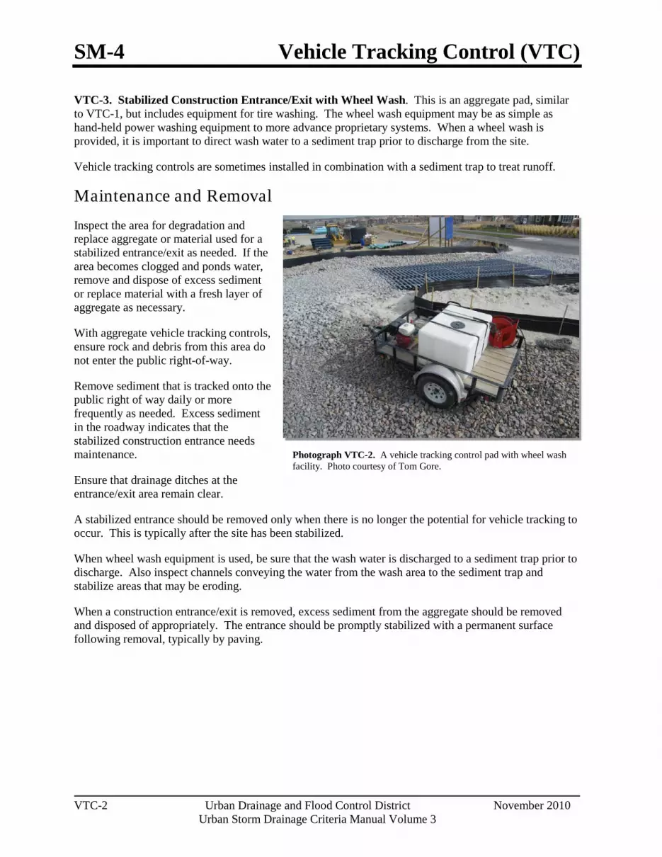
SM-4 Vehicle Tracking Control (VTC)
VTC-2 Urban Drainage and Flood Control District November 2010
Urban Storm Drainage Criteria Manual Volume 3
Photograph VTC-2. A vehicle tracking control pad with wheel wash facility. Photo courtesy of Tom Gore.
VTC-3. Stabilized Construction Entrance/Exit with Wheel Wash. This is an aggregate pad, similar to VTC-1, but includes equipment for tire washing. The wheel wash equipment may be as simple as hand-held power washing equipment to more advance proprietary systems. When a wheel wash is provided, it is important to direct wash water to a sediment trap prior to discharge from the site.
Vehicle tracking controls are sometimes installed in combination with a sediment trap to treat runoff.
Maintenance and Removal Inspect the area for degradation and replace aggregate or material used for a stabilized entrance/exit as needed. If the area becomes clogged and ponds water, remove and dispose of excess sediment or replace material with a fresh layer of aggregate as necessary.
With aggregate vehicle tracking controls, ensure rock and debris from this area do not enter the public right-of-way.
Remove sediment that is tracked onto the public right of way daily or more frequently as needed. Excess sediment in the roadway indicates that the stabilized construction entrance needs maintenance.
Ensure that drainage ditches at the entrance/exit area remain clear.
A stabilized entrance should be removed only when there is no longer the potential for vehicle tracking to occur. This is typically after the site has been stabilized.
When wheel wash equipment is used, be sure that the wash water is discharged to a sediment trap prior to discharge. Also inspect channels conveying the water from the wash area to the sediment trap and stabilize areas that may be eroding.
When a construction entrance/exit is removed, excess sediment from the aggregate should be removed and disposed of appropriately. The entrance should be promptly stabilized with a permanent surface following removal, typically by paving.

Vehicle Tracking Control (VTC) SM-4
November 2010 Urban Drainage and Flood Control District VTC-3 Urban Storm Drainage Criteria Manual Volume 3

SM-4 Vehicle Tracking Control (VTC)
VTC-4 Urban Drainage and Flood Control District November 2010
Urban Storm Drainage Criteria Manual Volume 3

Vehicle Tracking Control (VTC) SM-4
November 2010 Urban Drainage and Flood Control District VTC-5 Urban Storm Drainage Criteria Manual Volume 3

SM-4 Vehicle Tracking Control (VTC)
VTC-6 Urban Drainage and Flood Control District November 2010
Urban Storm Drainage Criteria Manual Volume 3

Stabilized Construction Roadway (SCR) SM-5
November 2010 Urban Drainage and Flood Control District SCR-1 Urban Storm Drainage Criteria Manual Volume 3
Photograph SCR-1. Stabilized construction roadway.
Description A stabilized construction roadway is a temporary method to control sediment runoff, vehicle tracking, and dust from roads during construction activities.
Appropriate Uses Use on high traffic construction roads to minimize dust and erosion.
Stabilized construction roadways are used instead of rough-cut street controls on roadways with frequent construction traffic.
Design and Installation Stabilized construction roadways typically involve two key components: 1) stabilizing the road surface with an aggregate base course of 3-inch-diameter granular material and 2) stabilizing roadside ditches, if applicable. Early application of road base is generally suitable where a layer of coarse aggregate is specified for final road construction.
Maintenance and Removal Apply additional gravel as necessary to ensure roadway integrity.
Inspect drainage ditches along the roadway for erosion and stabilize, as needed, through the use of check dams or rolled erosion control products.
Gravel may be removed once the road is ready to be paved. Prior to paving, the road should be inspected for grade changes and damage. Regrade and repair as necessary.
Stabilized Construction Roadway
Functions Erosion Control Yes Sediment Control Moderate Site/Material Management Yes

Stabilized Staging Area (SSA) SM-6
November 2010 Urban Drainage and Flood Control District SSA-1 Urban Storm Drainage Criteria Manual Volume 3
Photograph SSA-1. Example of a staging area with a gravel surface to prevent mud tracking and reduce runoff. Photo courtesy of Douglas County.
Description A stabilized staging area is a clearly designated area where construction equipment and vehicles, stockpiles, waste bins, and other construction-related materials are stored. The contractor office trailer may also be located in this area. Depending on the size of the construction site, more than one staging area may be necessary.
Appropriate Uses Most construction sites will require a staging area, which should be clearly designated in SWMP drawings. The layout of the staging area may vary depending on the type of construction activity. Staging areas located in roadways due to space constraints require special measures to avoid materials being washed into storm inlets.
Design and Installation Stabilized staging areas should be completed prior to other construction activities beginning on the site. Major components of a stabilized staging area include:
Appropriate space to contain storage and provide for loading/unloading operations, as well as parking if necessary.
A stabilized surface, either paved or covered, with 3-inch diameter aggregate or larger.
Perimeter controls such as silt fence, sediment control logs, or other measures.
Construction fencing to prevent unauthorized access to construction materials.
Provisions for Good Housekeeping practices related to materials storage and disposal, as described in the Good Housekeeping BMP Fact Sheet.
A stabilized construction entrance/exit, as described in the Vehicle Tracking Control BMP Fact Sheet, to accommodate traffic associated with material delivery and waste disposal vehicles.
Over-sizing the stabilized staging area may result in disturbance of existing vegetation in excess of that required for the project. This increases costs, as well as requirements for long-term stabilization following the construction period. When designing the stabilized staging area, minimize the area of disturbance to the extent practical.
Stabilized Staging Area Functions Erosion Control Yes Sediment Control Moderate Site/Material
Yes

SM-6 Stabilized Staging Area (SSA)
SSA-2 Urban Drainage and Flood Control District November 2010
Urban Storm Drainage Criteria Manual Volume 3
See Detail SSA-1 for a typical stabilized staging area and SSA-2 for a stabilized staging area when materials staging in roadways is required.
Maintenance and Removal Maintenance of stabilized staging areas includes maintaining a stable surface cover of gravel, repairing perimeter controls, and following good housekeeping practices.
When construction is complete, debris, unused stockpiles and materials should be recycled or properly disposed. In some cases, this will require disposal of contaminated soil from equipment leaks in an appropriate landfill. Staging areas should then be permanently stabilized with vegetation or other surface cover planned for the development.
Minimizing Long-Term Stabilization Requirements
Utilize off-site parking and restrict vehicle access to the site.
Use construction mats in lieu of rock when staging is provided in an area that will not be disturbed otherwise.
Consider use of a bermed contained area for materials and equipment that do not require a stabilized surface.
Consider phasing of staging areas to avoid disturbance in an area that will not be otherwise disturbed.
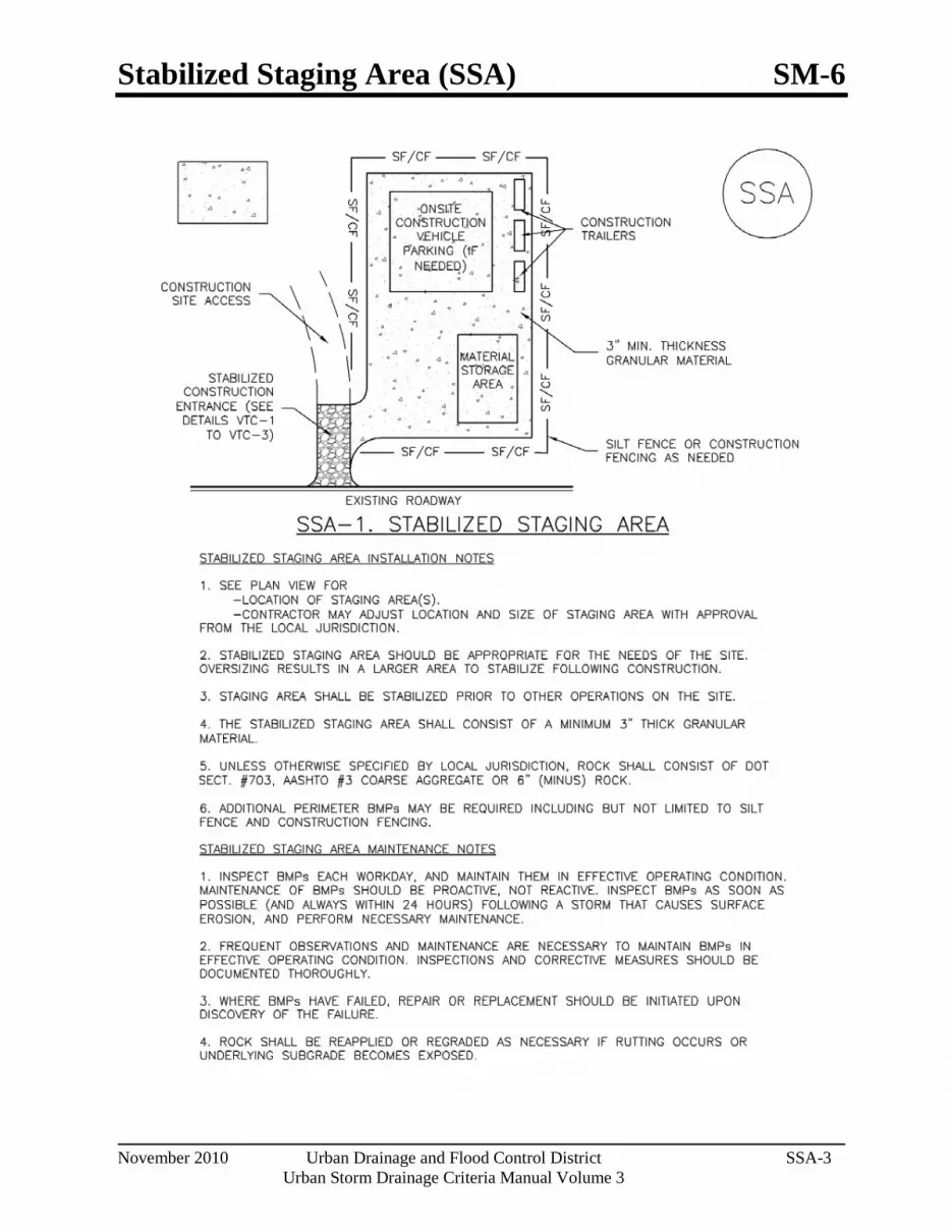
Stabilized Staging Area (SSA) SM-6
November 2010 Urban Drainage and Flood Control District SSA-3 Urban Storm Drainage Criteria Manual Volume 3

SM-6 Stabilized Staging Area (SSA)
SSA-4 Urban Drainage and Flood Control District November 2010
Urban Storm Drainage Criteria Manual Volume 3

Street Sweeping and Vacuuming (SS) SM-7
November 2010 Urban Drainage and Flood Control District SS-1 Urban Storm Drainage Criteria Manual Volume 3
Photograph SS-1. A street sweeper removes sediment and potential pollutants along the curb line at a construction site. Photo courtesy of Tom Gore.
Description Street sweeping and vacuuming remove sediment that has been tracked onto roadways to reduce sediment transport into storm drain systems or a surface waterway.
Appropriate Uses Use this practice at construction sites where vehicles may track sediment offsite onto paved roadways.
Design and Installation Street sweeping or vacuuming should be conducted when there is noticeable sediment accumulation on roadways adjacent to the construction site. Typically, this will be concentrated at the entrance/exit to the construction site. Well-maintained stabilized construction entrances, vehicle tracking controls and tire wash facilities can help reduce the necessary frequency of street sweeping and vacuuming.
On smaller construction sites, street sweeping can be conducted manually using a shovel and broom. Never wash accumulated sediment on roadways into storm drains.
Maintenance and Removal Inspect paved roads around the perimeter of the construction site on a daily basis and more
frequently, as needed. Remove accumulated sediment, as needed.
Following street sweeping, check inlet protection that may have been displaced during street sweeping.
Inspect area to be swept for materials that may be hazardous prior to beginning sweeping operations.
Street Sweeping/ Vacuuming
Functions Erosion Control No Sediment Control Yes Site/Material Management Yes

Temporary Diversion Methods (TDM) SM-8
June 2012 Urban Drainage and Flood Control District TDM-1 Urban Storm Drainage Criteria Manual Volume 3
Photograph TDM-1. This coffer dam, installed to allow grading and stabilization of the stream bank, consists of concrete blocks covered by an impermeable linear held in place by sand bags.
Description Temporary diversion methods are used to reroute water from a stream or restrict flows to a designated portion of the stream channel to allow for construction activities to take place in the stream, along the banks or beneath the active channel. Temporary diversion methods are often required during the construction of detention ponds, dams, in-stream grade control structures, utility installation and other activities, including maintenance, that require working in waterways. Temporary diversion methods include temporary diversion channels, pump-arounds, piped diversions, coffer dams and other similar practices. The primary purpose of all temporary diversion methods is to protect water quality by passing upstream flows around the active construction zone.
Appropriate Uses Temporary diversion methods are appropriate in situations when it is necessary to divert the flow around the area where work is being conducted. Temporary diversion methods vary with the size of the waterway that is being diverted.
For large streams, a temporary diversion may consist of berms or coffer dams constructed within the stream to confine flow to one side of the stream while work progresses on the “dry” side of the berm. For smaller streams and often for construction of dams and detention basins, a temporary diversion method may divert the entire waterway. For short duration projects (typically less than a month of active construction) with low baseflows, a pump and/or bypass pipe may serve as a temporary diversion. Whenever a temporary diversion is used, construction should be scheduled during drier times of the year (November through March) to the extent feasible, and construction in the waterway should progress as quickly as practical to reduce the risk of exceeding the temporary diversion capacity. Timing and duration of construction are primary considerations for determining the design flow most appropriate for a diversion. A sizing method that does not consider these variables is overly simplistic and can result in inflated project costs and land disturbances that provide little to no water quality benefit. Additionally, disturbing more area than necessary can result in increased erosion.
Temporary diversion method section and approach should occur on a project- and site-specific basis. For short duration projects (typically associated with maintenance of utilities and stream crossings and minor repairs to outfalls and eroded banks) constructed during dry times of the year, diversion construction can create greater disturbance and mobilization of sediment than all of the other earth disturbing activities of the project combined, and the cost of the diversion could be a significant percentage of the overall project cost. If it can be reasonably determined, based on area and duration of disturbance, that channel work will result in less disturbance and movement of sediment than would occur through installation of a temporary diversion, it is reasonable to exempt these activities from the requirement to construct a temporary diversion.
Temporary Diversion Channel Functions Erosion Control Yes Sediment Control No Site/Material Management No

SM-8 Temporary Diversion Methods (TDM)
TDM-2 Urban Drainage and Flood Control District June 2012
Urban Storm Drainage Criteria Manual Volume 3
On the other end of the spectrum, a basis of design for a temporary diversion in excess of the methodology presented in this Fact Sheet may be appropriate for longer duration projects and/or projects where the consequences of exceeding diversion capacity are significant in terms of public safety, damage to infrastructure and property, environmental impacts, damage or delay to the project and other factors. In short, engineers should recognize that temporary diversions must be thoughtfully analyzed on a case-by-case basis, considering site-specific circumstances.
Design Considerations Selection and design of temporary diversion methods should consider many factors, including:
Will construction of a temporary diversion cause greater environmental impacts than if the project is constructed without a temporary diversion? This frequently applies to short duration, small scale projects associated with maintenance activities such as bank erosion repair, drop structure and pond maintenance, outfall improvements/repair and other limited construction activities.
Size of stream, tributary watershed area and anticipated flow rates during construction. Special consideration should be given to large streams with large tributary areas with higher flow rates since the sizing methodology presented in this Fact Sheet is based on data from watersheds less than 20 square miles.
Any special water quality or aquatic life conditions the waterway.
Nature of surrounding land use, property ownership, and easements in the project area are important considerations in determining feasibility and methods for temporary diversions. For example, in a highly urbanized setting or an area with limited right-of-way, there may not be adequate space to construct a diversion channel.
Seasonal variations in stream hydrology (baseflow vs. peak flow). o Irrigation flows: If an irrigation ditch enters the stream, it is recommended that the ditch
company be contacted to confirm when flows from the ditch may be expected. o Weather (storm runoff): If diversions are constructed in summer months when
thunderstorms and flash flooding can occur, contractors will need to track weather forecasts closely and provide additional protection when higher flows from runoff are anticipated. The UDFCD Alert System can be used for daily forecasts and to provide warnings for severe weather.
Probability of flood flows exceeding diversion capacity and/or diversion failure. Consider the consequences of exceedance or failure such as:
o Public safety o Environmental o Legal o Regulatory o Economic o Project disruption/delay
Realistic estimation of project duration and time of year during which construction will occur.

Temporary Diversion Methods (TDM) SM-8
June 2012 Urban Drainage and Flood Control District TDM-3 Urban Storm Drainage Criteria Manual Volume 3
Comparison of the overall project costs to the temporary diversion costs (design and construction) and determining the costs and benefits of different diversion strategies relative to the protection that they provide.
Permitting requirements for overall project and for diversion methods (United States Army Corps of Engineers, United States Fish and Wildlife Service, Colorado Department of Public Health and Environment, Federal Emergency Management Agency, Division of Water Resources, local governments, and others). Permit requirements and existing vegetative cover may limit the allowable area disturbance.
Public safety aspects. For example, if a pipeline is being used, consideration should be given to public access and inlet protection.
Legal considerations, which are a function of many different factors such as property ownership, history of localized flooding, or parties that will have interest in project.
Design and Installation 1. Determine if a diversion is appropriate based on appropriate uses and design considerations stated
earlier. As noted, in some cases, constructing a project under wet conditions is preferable to constructing a temporary diversion to create dry conditions, especially if construction of the temporary diversion will require a significant amount of disturbance relative to the overall project.
2. Determine project duration.
“Long duration” projects are projects that last longer than three months and in many cases are Capital Improvement Projects or traditional land development projects.
“Short duration” projects are projects that are completed within one month or less and generally are associated with maintenance and repair activities.
“Interim duration” projects are projects that will last longer than one month but up to three months.
3. Determine the time of year in which construction will occur.
4. Gather necessary temporary diversion sizing parameters that may include tributary area, imperviousness, project duration safety factor, and seasonal sizing coefficient.
5. Apply applicable sizing methodology and perform necessary calculations (provided following this section). Use engineering judgment to determine if the temporary diversion design flow is adequate for the specific project.
6. Determine appropriate method of diversion. Follow the design steps for the selected method discussed below.
Channel Diversion – For smaller streams, construction of dams and detention basins, or as the site allows, a channel diversion may divert the entire waterway as illustrated in Figure TDM-1.
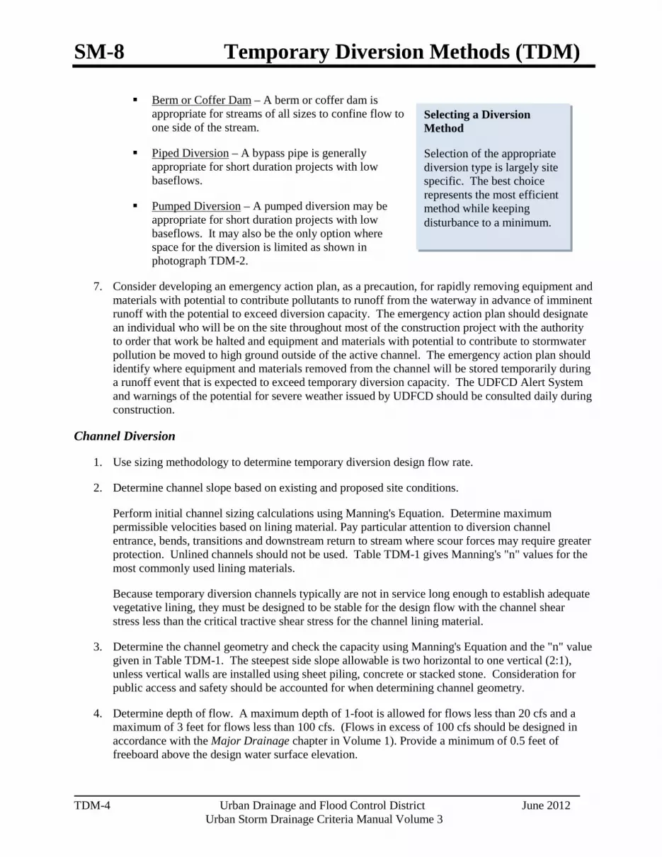
SM-8 Temporary Diversion Methods (TDM)
TDM-4 Urban Drainage and Flood Control District June 2012
Urban Storm Drainage Criteria Manual Volume 3
Selecting a Diversion Method
Selection of the appropriate diversion type is largely site specific. The best choice represents the most efficient method while keeping disturbance to a minimum.
Berm or Coffer Dam – A berm or coffer dam is appropriate for streams of all sizes to confine flow to one side of the stream.
Piped Diversion – A bypass pipe is generally appropriate for short duration projects with low baseflows.
Pumped Diversion – A pumped diversion may be appropriate for short duration projects with low baseflows. It may also be the only option where space for the diversion is limited as shown in photograph TDM-2.
7. Consider developing an emergency action plan, as a precaution, for rapidly removing equipment and materials with potential to contribute pollutants to runoff from the waterway in advance of imminent runoff with the potential to exceed diversion capacity. The emergency action plan should designate an individual who will be on the site throughout most of the construction project with the authority to order that work be halted and equipment and materials with potential to contribute to stormwater pollution be moved to high ground outside of the active channel. The emergency action plan should identify where equipment and materials removed from the channel will be stored temporarily during a runoff event that is expected to exceed temporary diversion capacity. The UDFCD Alert System and warnings of the potential for severe weather issued by UDFCD should be consulted daily during construction.
Channel Diversion
1. Use sizing methodology to determine temporary diversion design flow rate.
2. Determine channel slope based on existing and proposed site conditions.
Perform initial channel sizing calculations using Manning's Equation. Determine maximum permissible velocities based on lining material. Pay particular attention to diversion channel entrance, bends, transitions and downstream return to stream where scour forces may require greater protection. Unlined channels should not be used. Table TDM-1 gives Manning's "n" values for the most commonly used lining materials.
Because temporary diversion channels typically are not in service long enough to establish adequate vegetative lining, they must be designed to be stable for the design flow with the channel shear stress less than the critical tractive shear stress for the channel lining material.
3. Determine the channel geometry and check the capacity using Manning's Equation and the "n" value given in Table TDM-1. The steepest side slope allowable is two horizontal to one vertical (2:1), unless vertical walls are installed using sheet piling, concrete or stacked stone. Consideration for public access and safety should be accounted for when determining channel geometry.
4. Determine depth of flow. A maximum depth of 1-foot is allowed for flows less than 20 cfs and a maximum of 3 feet for flows less than 100 cfs. (Flows in excess of 100 cfs should be designed in accordance with the Major Drainage chapter in Volume 1). Provide a minimum of 0.5 feet of freeboard above the design water surface elevation.

Temporary Diversion Methods (TDM) SM-8
June 2012 Urban Drainage and Flood Control District TDM-5 Urban Storm Drainage Criteria Manual Volume 3
Table TDM-1. Manning’s n Values for Temporary Diversion Channel Design
Lining Material Manning's n Depth = 0 to 1.0 ft
Manning's n Depth = 1.0 to 3.0 ft
Manning's n Depth = 3.0 to 5.0 ft
Plastic Membrane 0.011 0.010 0.009 Straw/Curled Wood Mats 0.035 0.025 0.020 Riprap, Type VL 0.070 0.045 0.035 Riprap, Type L 0.100 0.070 0.040 Riprap, Type M 0.125 0.075 0.045 Note: Use manufacturer's Manning's n when available. See the Major Drainage chapter of the USDCM for riprap gradation. Erosion protection should extend a minimum of 0.5 feet above the design water depth.
Berm or Coffer Dam
For coffer dams or berms that are intended to isolate a portion of the stream from the work area steps 1-4 should be applied to the “wet” side of the coffer dam or berm.
1. Use sizing methodology to determine temporary diversion design flow rate.
2. Determine channel slope based on existing and proposed site conditions.
3. Perform initial channel sizing calculations using Manning's Equation. Determine maximum permissible velocities based on lining material. Because temporary diversion measures typically are not in service long enough to establish adequate vegetative lining, they must be designed to be stable for the design flow with the channel shear stress less than the critical tractive shear stress for the channel lining material. This stability criterion applies to the stream-side of berms when berms are used to isolate a work area within a stream.
4. Determine the channel geometry and check the capacity using Manning's Equation and the "n" value given in Table TDM-1. The steepest side slope allowable is two horizontal to one vertical (2:1), unless vertical walls are installed using sheet piling, concrete or stacked stone. Provide a minimum of 0.5 feet of freeboard above the design water surface elevation.
Piped Diversion
1. Use sizing methodology to determine temporary diversion design flow rate.
2. Size the pipe to accommodate the design flow using no more than 80 percent of the pipe full flow capacity. Select a Manning’s n value based on the type of pipe material that will be used (concrete n = 0.013 [typ.], corrugated metal pipe n = 0.024 [typ.]).

SM-8 Temporary Diversion Methods (TDM)
TDM-6 Urban Drainage and Flood Control District June 2012
Urban Storm Drainage Criteria Manual Volume 3
“Long duration” projects last longer than three months.
“Short duration” projects are
completed within one month or less.
“Interim duration” projects last longer than one month and up
to three months.
Photograph TDM-2. Despite a relatively significant baseflow, a pumped diversion was selected for this Lakewood Gulch project due to a lack of space crossing Federal Boulevard. Photo courtesy of City and County of Denver.
Pumped Diversion
1. Use sizing methodology to determine temporary diversion design flow rate.
2. A backup pump (or pumps) with capacity equal to or greater than the diversion design flow rate should be on site and in good working order at all times.
Sizing Methodology The methodology for sizing of temporary diversion methods was developed using baseflow observations and Crest Stage Indicator (CSI) peak flow data collected from 21 watersheds within the UDFCD boundary. These data were collected over extended periods of time (up to 31 years) and, as a result, provide a sound statistical basis for the sizing methodology.
Determine sizing procedure to use based on the project duration.
• “Long duration” projects last longer than three months and in many cases are Capital Improvement Projects or traditional land development projects.
• “Short duration” projects are completed within one
month or less and generally are associated with maintenance and repair activities. For these projects, it is recommended that the temporary diversion be sized based on the statistics identified for baseflows (i.e., vs. peak flows) and be of sufficient size to convey a flow that has a less than 50% chance of being exceeded between November – March, including a project duration safety factor.
• “Interim duration” projects will last longer than one month but up to three months. In these projects,
engineering judgment must be applied, drawing on sizing methods for “short duration” and “long duration” project criteria and the time of year of construction to develop a basis of design for the temporary diversion method that is appropriate for the project.
It is highly recommended that projects involving temporary diversions be constructed between November and March. If a short duration project requiring a temporary diversion must be conducted between April and October, the extended weather forecast should be evaluated to avoid periods of anticipated precipitation and a conservative safety factor should be applied. Additional protection may need to be provided for the site if higher flows from runoff are anticipated.

Temporary Diversion Methods (TDM) SM-8
June 2012 Urban Drainage and Flood Control District TDM-7 Urban Storm Drainage Criteria Manual Volume 3
Sizing Procedure for Long Duration Projects (duration greater than three months)
1. Determine the tributary drainage area, A, in square miles.
2. Determine the watershed imperviousness (adjusted as appropriate for disconnected impervious area, see Chapter 3).
3. Determine the design peak flow rate according to Figure TDM-2. Note: For long duration projects, or where the consequences of diversion failure warrant, a larger design flow may be necessary, and/or a more detailed, site-specific hydrologic analysis.
Figure TDM-2 may be used to estimate the design discharge for the sizing of temporary diversion methods for projects exceeding three months in duration. The curves in this figure were originally developed using annual peak flow data collected from 17 watersheds within the UDFCD boundary and then updated in 2012 using annual peak flow data from 21 watersheds with CSI gages. These data were collected over extended periods of time (up to 31 years) and, as a result, provide a sound statistical basis for the figure. The data supporting Figure TDM-2 were taken during the high flood potential period of April through September.
Figure TDM-2 provides estimated 2-year peak flow rates with the upper 5% and lower 95% confidence limits shown and is based on watershed imperviousness for small waterways (25 square miles or less).1
Because Figure TDM-2 was developed using data from small watersheds, it is not appropriate to extrapolate from this figure for larger, more complex watersheds. For larger waterways (e.g., South Platte River, Sand Creek, Bear Creek, etc.), including ones controlled by flood control reservoirs (e.g., Chatfield Dam, Cherry Creek Dam, etc.), site-specific hydrologic analysis and risk assessment will be necessary to evaluate the appropriate level of protection to be provided by the temporary diversion. For any size watershed, it is important that the designer understand watershed characteristics to determine applicability of the simplified method and how these characteristics influence the choice of diversion method. It is also important to recognize that larger floods can and do occur. It is the responsibility of the designer and the contractor to assess their risk of having the temporary diversion being exceeded and to evaluate the damages such an event may cause to the project, adjacent properties and others.
1 There are a multitude of factors affecting rainfall-runoff response of a watershed in addition to impervious area. Other factors include soil types, total area, fraction of connected/disconnected impervious area, watershed shape, topography and many other factors). Figure TDM-2 provides a simplified design tool based on watershed imperviousness but should not be blindly relied upon without due consideration of other factors including those listed above and others.

SM-8 Temporary Diversion Methods (TDM)
TDM-8 Urban Drainage and Flood Control District June 2012
Urban Storm Drainage Criteria Manual Volume 3
When a diversion is determined to be appropriate, safety factors and K values in Table TDM-2 are minimum recommended
values. Depending on the many factors to consider in selecting
and sizing a temporary diversion listed above, higher
values for K and S may be appropriate.
Sizing Procedure for Short Duration Projects (one month or less of active construction)
1. Determine the tributary drainage area, A, in square miles.
2. Select a safety factor, S, based on project duration from Table TDM-2. Short duration projects have been broken down further into projects less than two weeks and projects from two weeks up to one month.
3. Select the sizing coefficient, K, corresponding to the month in which the project will occur (see Table TDM-2). For projects that span two months with different K values, use the greater of the two K values. For short duration projects that will occur during the traditionally dry period of the year (November through March) a K value of 0.2 is recommended. For short duration projects that will occur April through October, and wet weather is not predicted, a K value of 0.5 is recommended.
Table TDM-2.Temporary Diversion Sizing Coefficients and Safety Factors for
Short Duration Projects
Time of Year Project Duration Safety Factor , S Temporary Diversion Sizing Coefficient, K
November - March Less than 2 weeks 1.0 0.2 November - March 2 weeks to 1 month 1.5 0.2
April - October Less than 2 weeks
(during dry weather conditions)
1.0 0.5
April - October 2 weeks to 1 month 1.5 0.5 Note: K coefficients were developed from regression analysis of baseflow data from USGS Crest Stage Indicator (CSI) data to approximate flows that have a less than 50% chance of being exceeded between November - March.
4. Calculate the recommended temporary diversion design flow rate using equation TDM-1:
Q = S K A (Equation TDM-1)
In which, Q = temporary diversion design flow rate for short-duration projects (cfs).
S = safety factor coefficient from Table TDM-2 based on duration.
K = diversion sizing coefficient from Table TDM-2 based on seasonality.
A = tributary area (square miles).
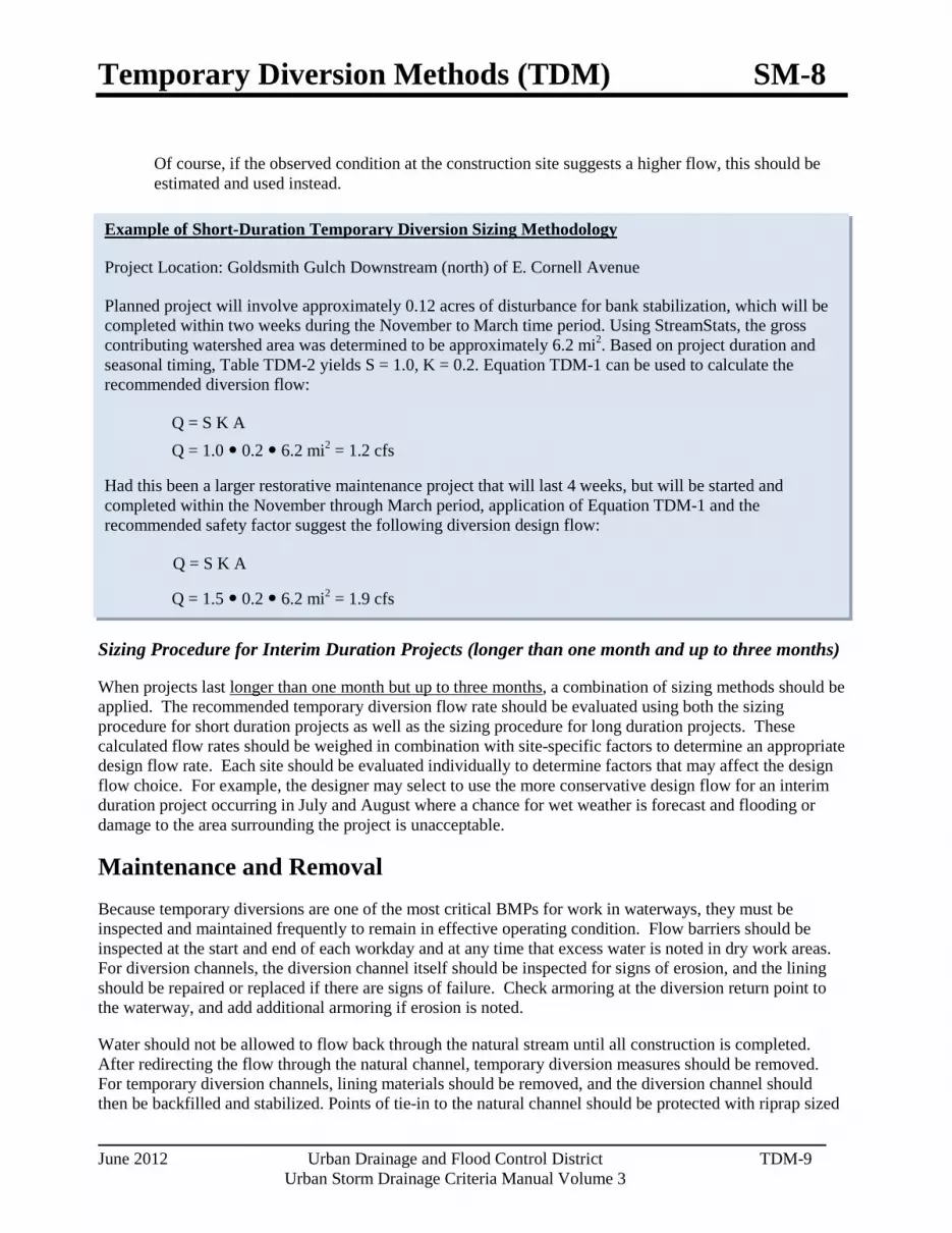
Temporary Diversion Methods (TDM) SM-8
June 2012 Urban Drainage and Flood Control District TDM-9 Urban Storm Drainage Criteria Manual Volume 3
Example of Short-Duration Temporary Diversion Sizing Methodology
Project Location: Goldsmith Gulch Downstream (north) of E. Cornell Avenue
Planned project will involve approximately 0.12 acres of disturbance for bank stabilization, which will be completed within two weeks during the November to March time period. Using StreamStats, the gross contributing watershed area was determined to be approximately 6.2 mi2. Based on project duration and seasonal timing, Table TDM-2 yields S = 1.0, K = 0.2. Equation TDM-1 can be used to calculate the recommended diversion flow:
Q = S K A Q = 1.0 0.2 6.2 mi2 = 1.2 cfs
Had this been a larger restorative maintenance project that will last 4 weeks, but will be started and completed within the November through March period, application of Equation TDM-1 and the recommended safety factor suggest the following diversion design flow:
Q = S K A
Q = 1.5 0.2 6.2 mi2 = 1.9 cfs
Of course, if the observed condition at the construction site suggests a higher flow, this should be estimated and used instead.
Sizing Procedure for Interim Duration Projects (longer than one month and up to three months)
When projects last longer than one month but up to three months, a combination of sizing methods should be applied. The recommended temporary diversion flow rate should be evaluated using both the sizing procedure for short duration projects as well as the sizing procedure for long duration projects. These calculated flow rates should be weighed in combination with site-specific factors to determine an appropriate design flow rate. Each site should be evaluated individually to determine factors that may affect the design flow choice. For example, the designer may select to use the more conservative design flow for an interim duration project occurring in July and August where a chance for wet weather is forecast and flooding or damage to the area surrounding the project is unacceptable.
Maintenance and Removal Because temporary diversions are one of the most critical BMPs for work in waterways, they must be inspected and maintained frequently to remain in effective operating condition. Flow barriers should be inspected at the start and end of each workday and at any time that excess water is noted in dry work areas. For diversion channels, the diversion channel itself should be inspected for signs of erosion, and the lining should be repaired or replaced if there are signs of failure. Check armoring at the diversion return point to the waterway, and add additional armoring if erosion is noted.
Water should not be allowed to flow back through the natural stream until all construction is completed. After redirecting the flow through the natural channel, temporary diversion measures should be removed. For temporary diversion channels, lining materials should be removed, and the diversion channel should then be backfilled and stabilized. Points of tie-in to the natural channel should be protected with riprap sized

SM-8 Temporary Diversion Methods (TDM)
TDM-10 Urban Drainage and Flood Control District June 2012
Urban Storm Drainage Criteria Manual Volume 3
in accordance with the Major Drainage chapter in Volume 1.
Figure TDM-1. Typical Temporary Diversion Channel
Former Location of Stream Bank
Former Location of Stream Bank

Temporary Diversion Methods (TDM) SM-8
June 2012 Urban Drainage and Flood Control District TDM-11 Urban Storm Drainage Criteria Manual Volume 3
Figure TDM-2. Temporary Diversion Facility Sizing Nomograph for Long Duration Projects
(Duration in excess of three months) Based on 2-year Peak Flows - Denver Metropolitan and Adjacent Areas, Updated April 2012

SM-8 Temporary Diversion Methods (TDM)
TDM-12 Urban Drainage and Flood Control District June 2012
Urban Storm Drainage Criteria Manual Volume 3

Temporary Diversion Methods (TDM) SM-8
June 2012 Urban Drainage and Flood Control District TDM-13 Urban Storm Drainage Criteria Manual Volume 3

Dewatering Operations (DW) SM-9
November 2010 Urban Drainage and Flood Control District DW-1 Urban Storm Drainage Criteria Manual Volume 3
Photograph DW-1. A relatively small dewatering operation using straw bales and a dewatering bag.
Photograph DW-2. Dewatering bags used for a relatively large dewatering operation.
Description The BMPs selected for construction dewatering vary depending on site-specific features such as soils, topography, anticipated discharge quantities, and discharge location. Dewatering typically involves pumping water from an inundated area to a BMP, and then downstream to a receiving waterway, sediment basin, or well-vegetated area. Dewatering typically involves use of several BMPs in sequence.
Appropriate Uses Dewatering operations are used when an area of the construction site needs to be dewatered as the result of a large storm event, groundwater, or existing ponding conditions. This can occur during deep excavation, utility trenching, and wetland or pond excavation.
Design and Installation Dewatering techniques will vary depending on site conditions. However, all dewatering discharges must be treated to remove sediment before discharging from the construction site. Discharging water into a sediment trap or basin is an acceptable treatment option. Water may also be treated using a dewatering filter bag, and a series of straw bales or sediment logs. If these previous options are not feasible due to space or the ability to passively treat the discharge to remove sediment, then a settling tank or an active treatment system may need to be utilized. Settling tanks are manufactured tanks with a series of baffles to promote settling. Flocculants can also be added to the tank to induce more rapid settling. This is an approach sometimes used on highly urbanized construction sites. Contact the state agency for special requirements prior to using flocculents and land application techniques.
Some commonly used methods to handle the pumped water without surface discharge include land application to vegetated areas through a perforated discharge hose (i.e., the "sprinkler method") or dispersal from a water truck for dust control.
Dewatering Operations Functions Erosion Control Moderate Sediment Control Yes Site/Material Management Yes
SM-9 Dewatering Operations (DW)
DW-2 Urban Drainage and Flood Control District November 2010
Urban Storm Drainage Criteria Manual Volume 3
Dewatering discharges to non-paved areas must minimize the potential for scour at the discharge point either using a velocity dissipation device or dewatering filter bag.
Design Details are provided for these types of dewatering situations:
DW-1. Dewatering for Pond Already Filled with Water
DW-2 Dewatering Sump for Submersed Pump
DW-3 Sump Discharge Settling Basin
DW-4 Dewatering Filter Bag
Maintenance and Removal When a sediment basin or trap is used to enable settling of sediment from construction dewatering discharges, inspect the basin for sediment accumulation. Remove sediment prior to the basin or trap reaching half full. Inspect treatment facilities prior to any dewatering activity. If using a sediment control practice such as a sediment trap or basin, complete all maintenance requirements as described in the fact sheets prior to dewatering.
Properly dispose of used dewatering bags, as well as sediment removed from the dewatering BMPs. Depending on the size of the dewatering operation, it may also be necessary to revegetate or otherwise stabilize the area where the dewatering operation was occurring.
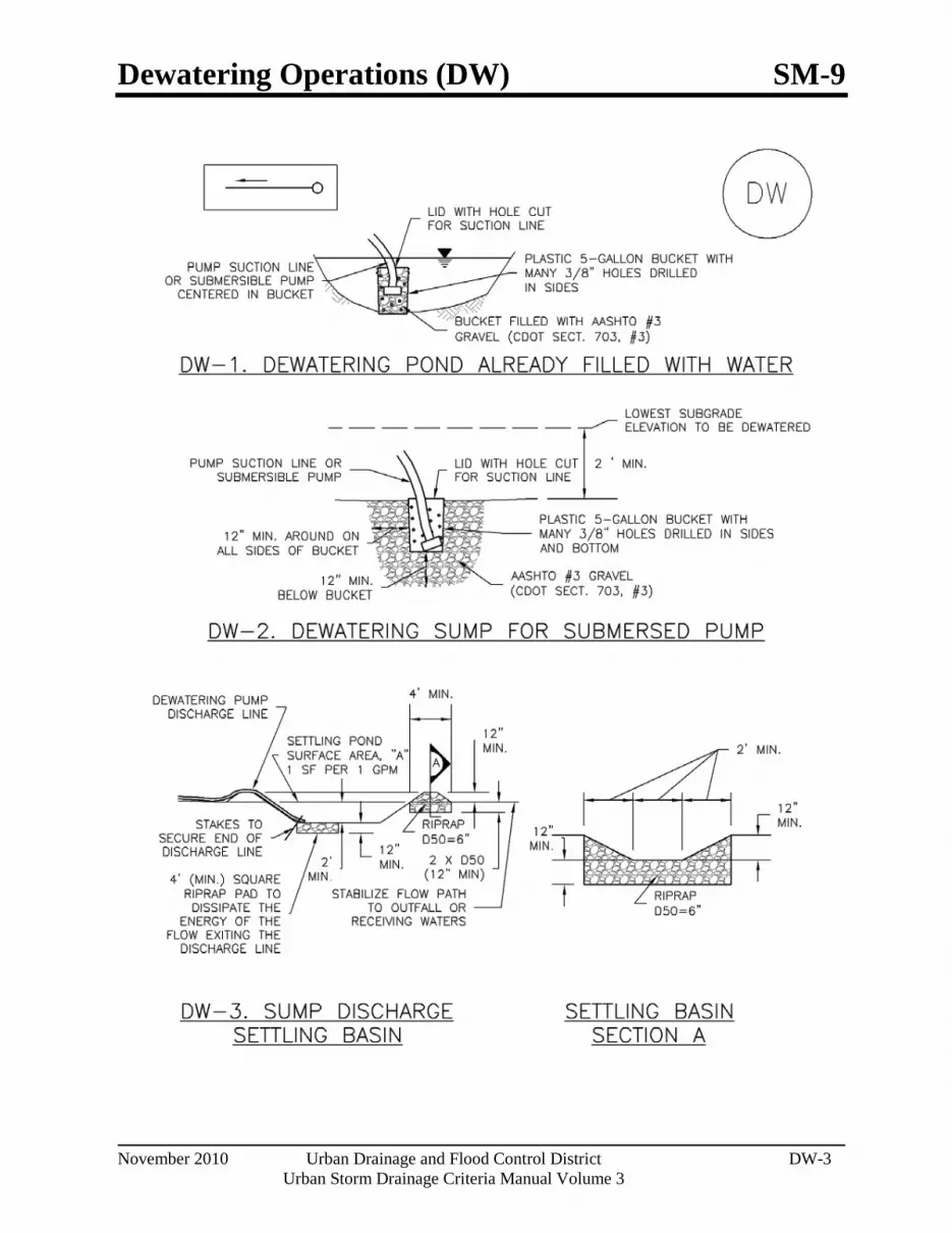
Dewatering Operations (DW) SM-9
November 2010 Urban Drainage and Flood Control District DW-3 Urban Storm Drainage Criteria Manual Volume 3
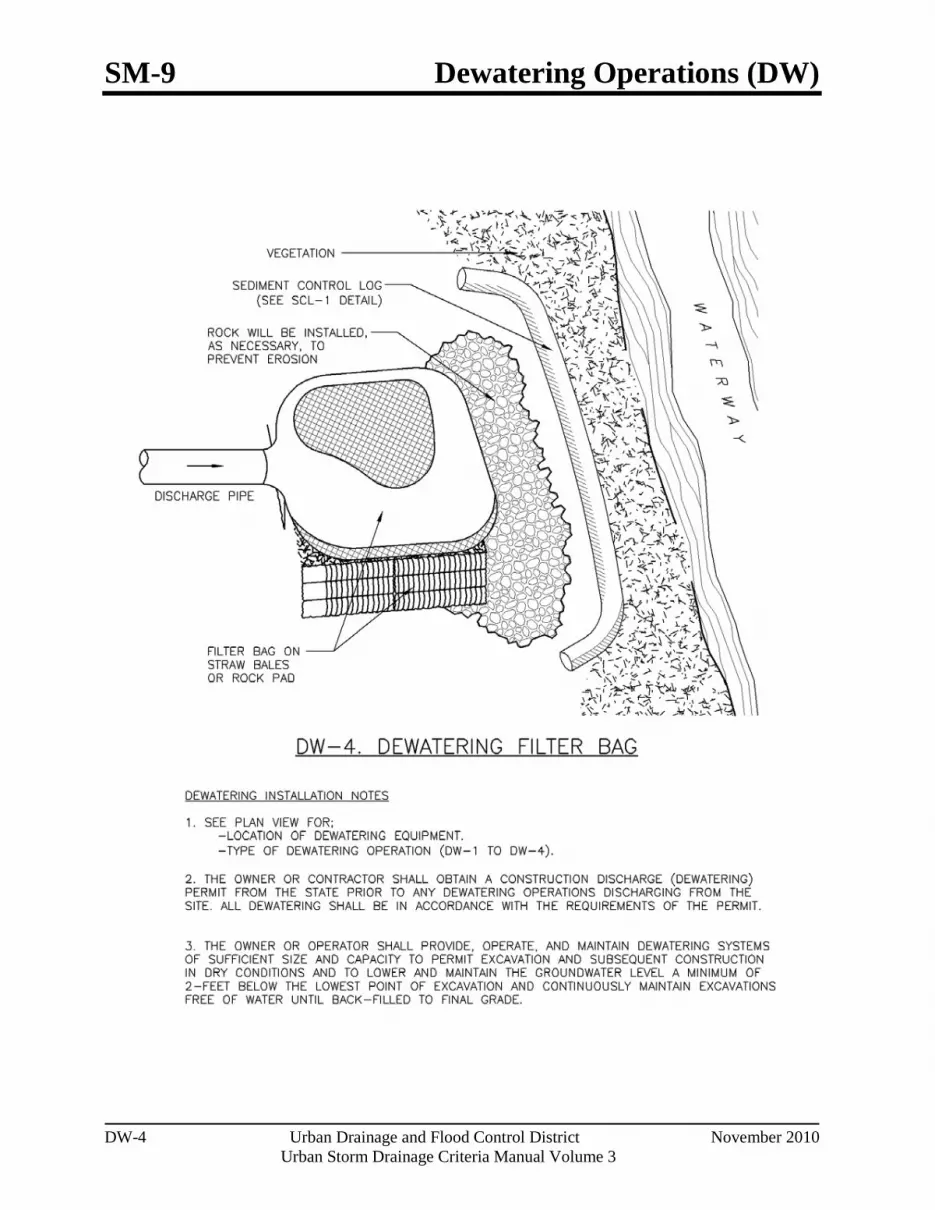
SM-9 Dewatering Operations (DW)
DW-4 Urban Drainage and Flood Control District November 2010
Urban Storm Drainage Criteria Manual Volume 3

Dewatering Operations (DW) SM-9
November 2010 Urban Drainage and Flood Control District DW-5 Urban Storm Drainage Criteria Manual Volume 3

Temporary Stream Crossing (TSC) SM-10
June 2012 Urban Drainage and Flood Control District TSC-1 Urban Storm Drainage Criteria Manual Volume 3
Description Where an actively flowing watercourse must be crossed regularly by construction vehicles, a temporary crossing should be provided. Three primary methods are available:
Culvert crossing
Stream ford
Temporary bridge
Culvert crossings and fords are the most commonly used methods. Due to the expense associated with a temporary bridge, these are used primarily on long-term projects.
Appropriate Uses Construction vehicles shall be kept out of waterways to the maximum extent practicable. Use a temporary stream crossing when it is absolutely necessary to cross a stream on a construction site. Construct a temporary crossing even if the stream or drainageway is typically dry. Multiple stream crossings should be avoided to minimize environmental impacts.
A permit is required for placement of fill in a waterway under Section 404 of the Clean Water Act. The local office of the U.S. Army Corps of Engineers (USACE) should be contacted concerning the requirements for obtaining a 404 permit. In addition, a permit from the U.S. Fish and Wildlife Service (USFWS) may be needed if endangered species are of concern in the work area. Typically, the USFWS issues are addressed by a 404 permit, if one is required. The municipality of jurisdiction should also be consulted, and can provide assistance. Other permits to be obtained may include a floodplain development permit from the local jurisdiction.
Design and Installation Design details are provided for these types of stream crossings:
TSC-1. Culvert Crossing
TSC-2. Ford Crossing
TSC-3. Flume Crossing
Temporary Stream Crossing Functions Erosion Control Yes Sediment Control Yes Site/Material Management No
Photograph TSC-1. A temporary stream crossing using culverts. Photo courtesy of Tom Gore.

SM-10 Temporary Stream Crossing (TSC)
TSC-2 Urban Drainage and Flood Control District June 2012
Urban Storm Drainage Criteria Manual Volume 3
A culvert crossing should be sized appropriately with consideration for the duration of construction and seasonal variation of flows. The sizing methodology provided in the Temporary Diversion Methods Fact Sheet is also appropriate for determining the design flow for temporary stream crossings. Culvert sizing must account for the headwater and tailwater controls to properly size the culvert. For additional discussion on design of box culverts and pipes, see the Major Drainage chapter in Volume 1. The designer also needs to confirm that the riprap selected is appropriate for the conditions in the channel being crossed.
When a ford must be used, namely when a culvert is not practical or the best solution, the ford should be lined with at least a 12-inch thick layer of Type VL (D50 = 6 inches) or Type L (D50 = 9 inches) riprap with void spaces filed with 1-1/2 inch diameter rock. Ford crossings are recommended primarily for crossings of ephemeral (i.e. intermittently, briefly flowing) streams.
For a temporary bridge crossing, consult with a structural and/or geotechnical engineer for temporary bridge design or consider pre-fabricated alternatives.
Maintenance and Removal Inspect stream for bank erosion and in-stream degradation. If bank erosion is occurring, stabilize banks using erosion control practices such as erosion control blankets. If in-stream degradation is occurring, armor the culvert outlet(s) with riprap to dissipate energy. If sediment is accumulating upstream of the crossing, remove excess sediment as needed to maintain the functionality of the crossing.
Remove the temporary crossing when it is no longer needed for construction. Take care to minimize the amount of sediment lost into the stream upon removal. Once the crossing has been removed, stabilize the stream banks with seed and erosion control blankets.
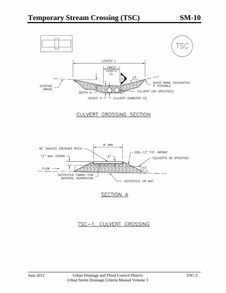
Temporary Stream Crossing (TSC) SM-10
June 2012 Urban Drainage and Flood Control District TSC-3 Urban Storm Drainage Criteria Manual Volume 3

SM-10 Temporary Stream Crossing (TSC)
TSC-4 Urban Drainage and Flood Control District June 2012
Urban Storm Drainage Criteria Manual Volume 3

Temporary Stream Crossing (TSC) SM-10
June 2012 Urban Drainage and Flood Control District TSC-5 Urban Storm Drainage Criteria Manual Volume 3

SM-10 Temporary Stream Crossing (TSC)
TSC-6 Urban Drainage and Flood Control District June 2012
Urban Storm Drainage Criteria Manual Volume 3

Temporary Batch Plant (TBP) SM-11
November 2010 Urban Drainage and Flood Control District TBP-1 Urban Storm Drainage Criteria Manual Volume 3
Photograph TBP-1. Effective stormwater management at temporary batch plants requires implementation of multiple BMPs. Photo courtesy of California Stormwater BMP Handbook.
Descr iption Temporary batch plant management includes implementing multiple BMPs such as perimeter controls, concrete washout area, stabilized construction access, good housekeeping, and other practices designed to reduce polluted runoff from the batch plant area.
Appropr iate Uses Implement this BMP at temporary batch plants and identify the location of the batch plant in the SWMP.
Additional permitting may be required for the operation of batch plants depending on their duration and location.
Design and Installation The following lists temporary management strategies to mitigate runoff from batch plant operations:
When stockpiling materials, follow the Stockpile Management BMP.
Locate batch plants away from storm drains and natural surface waters.
A perimeter control should be installed around the temporary batch plant.
Install run-on controls where feasible.
A designated concrete washout should be located within the perimeter of the site following the procedures in the Concrete Washout Area BMP.
Follow the Good Housekeeping BMP, including proper spill containment measures, materials storage, and waste storage practices.
A stabilized construction entrance or vehicle tracking control pad should be installed at the plant entrance, in accordance with the Vehicle Tracking Control BMP.
Maintenance and Removal Inspect the batch plant for proper functioning of the BMPs, with attention to material and waste storage areas, integrity of perimeter BMPs, and an effective stabilized construction entrance.
Temporary Batch Plants
Functions Erosion Control No Sediment Control No Site/Material Management Yes

SM-11 Temporary Batch Plant (TBP)
TBP-2 Urban Drainage and Flood Control District November 2010
Urban Storm Drainage Criteria Manual Volume 3
After the temporary batch plant is no longer needed, remove stockpiled materials and equipment, regrade the site as needed, and revegetate or otherwise stabilize the area.

Paving and Grinding Operations (PGO) SM-12
November 2010 Urban Drainage and Flood Control District PGO-1 Urban Storm Drainage Criteria Manual Volume 3
Photograph PGO-1. Paving operations on a Colorado highway. Photo courtesy of CDOT.
Description Manage runoff from paving and grinding operations to reduce pollutants entering storm drainage systems and natural drainageways.
Appropriate Uses Use runoff management practices during all paving and grinding operations such as surfacing, resurfacing, and saw cutting.
Design and Installation There are a variety of management strategies that can be used to manage runoff from paving and grinding operations:
Establish inlet protection for all inlets that could potentially receive runoff.
Schedule paving operations when dry weather is forecasted.
Keep spill kits onsite for equipment spills and keep drip pans onsite for stored equipment.
Install perimeter controls when asphalt material is used on embankments or shoulders near waterways, drainages, or inlets.
Do not wash any paved surface into receiving storm drain inlets or natural drainageways. Instead, loose material should be swept or vacuumed following paving and grinding operations.
Store materials away from drainages or waterways.
Recycle asphalt and pavement material when feasible. Material that cannot be recycled must be disposed of in accordance with applicable regulations.
See BMP Fact Sheets for Inlet Protection, Silt Fence and other perimeter controls selected for use during paving and grinding operations.
Maintenance and Removal Perform maintenance and removal of inlet protection and perimeter controls in accordance with their respective fact sheets.
Promptly respond to spills in accordance with the spill prevention and control plan.
Paving and Grinding Operations
Functions Erosion Control No Sediment Control No Site/Material Management Yes

Bibliography
November 2010 Urban Drainage and Flood Control District Bibliography-7
Urban Storm Drainage Criteria Manual Volume 3
Water Environment Federation (WERF). 2005. Critical Assessment of Stormwater Treatment Controls and Control Selection Issues. 02-SW-01. WERF: Alexandria, VA: IWA Publishing: London.
Water Environment Federation and American Society of Civil Engineers. 1998. Urban Runoff Quality Management, WEF Manual of Practice No. 23 and ASCE Manual and Report on Engineering Practice NO. 87. Water Environment Federation (WEF): Alexandria, VA.
Watershed Management Institute. 1997. Operation, Maintenance and Management of Stormwater Management Systems. Watershed Management Institute: Ingleside, MD.
Werthmann, C. 2007 Green Roof: A Case Study: Michael Van Valkenburgh Associates' Design for the Headquarters of the American Society of Landscape Architects. Princeton Architectural Press: New York, New York.
Wischmeier, W.H. and D.D. Smith. 1978. Predicting rainfall erosion losses: A guide to conservation planning. Agriculture Handbook No. 537, US Dept. of Agriculture. Washington, DC.
Wischmeier, W.H. and D.D. Smith. 1965. Predicting rainfall-erosion losses from cropland east of the Rocky Mountains. Agriculture Handbook No. 282, US Dept. of Agriculture. Washington, DC.
Wright Water Engineers and Geosyntec Consultants. 2010. International Stormwater Best Management Practices Database Pollutant Category Summary: Fecal Indicator Bacteria. Prepared for WERF, FHWA and EWRI-ASCE.
Wright Water Engineers, Inc., Wenk Associates, Muller Engineering Company, Inc., Matrix Design Group, and Smith Environmental. 2004. City and County of Denver Water Quality Management Plan. Denver, CO
Wulliman, J.T., M. Maxwell, W.E. Wenk, and B. Urbonas. 1988. Multiple Treatment Systems for Phosphorous Removal. Design of Urban Runoff Quality Controls. Proceedings of the Engineering Foundation Conference: Potosi, MO.

Check Dams (CD) EC-12
November 2010 Urban Drainage and Flood Control District CD-1 Urban Storm Drainage Criteria Manual Volume 3
Photograph CD-1. Rock check dams in a roadside ditch. Photo courtesy of WWE.
Description Check dams are temporary grade control structures placed in drainage channels to limit the erosivity of stormwater by reducing flow velocity. Check dams are typically constructed from rock, gravel bags, sand bags, or sometimes, proprietary devices. Reinforced check dams are typically constructed from rock and wire gabion. Although the primary function of check dams is to reduce the velocity of concentrated flows, a secondary benefit is sediment trapping upstream of the structure.
Appropriate Uses Use as a grade control for temporary drainage ditches or swales until final soil stabilization measures are established upstream and downstream. Check dams can be used on mild or moderately steep slopes. Check dams may be used under the following conditions:
As temporary grade control facilities along waterways until final stabilization is established.
Along permanent swales that need protection prior to installation of a non-erodible lining.
Along temporary channels, ditches or swales that need protection where construction of a non-erodible lining is not practicable.
Reinforced check dams should be used in areas subject to high flow velocities.
Design and Installation Place check dams at regularly spaced intervals along the drainage swale or ditch. Check dams heights should allow for pools to develop upstream of each check dam, extending to the downstream toe of the check dam immediately upstream.
When rock is used for the check dam, place rock mechanically or by hand. Do not dump rocks into the drainage channel. Where multiple check dams are used, the top of the lower dam should be at the same elevation as the toe of the upper dam.
When reinforced check dams are used, install erosion control fabric under and around the check dam to prevent erosion on the upstream and downstream sides. Each section of the dam should be keyed in to reduce the potential for washout or undermining. A rock apron upstream and downstream of the dam may be necessary to further control erosion.
Check Dams
Functions Erosion Control Yes Sediment Control Moderate Site/Material Management No
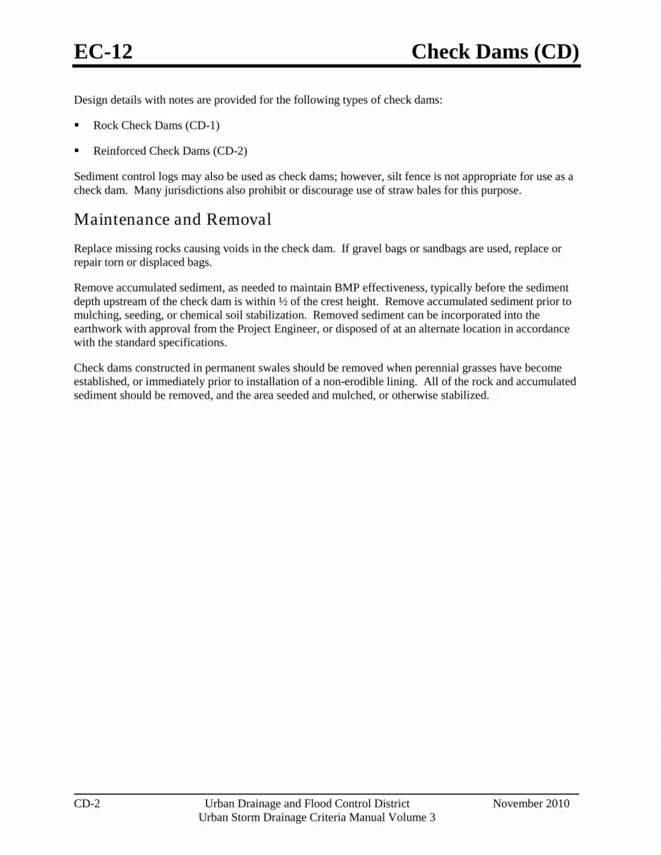
EC-12 Check Dams (CD)
CD-2 Urban Drainage and Flood Control District November 2010
Urban Storm Drainage Criteria Manual Volume 3
Design details with notes are provided for the following types of check dams:
Rock Check Dams (CD-1)
Reinforced Check Dams (CD-2)
Sediment control logs may also be used as check dams; however, silt fence is not appropriate for use as a check dam. Many jurisdictions also prohibit or discourage use of straw bales for this purpose.
Maintenance and Removal Replace missing rocks causing voids in the check dam. If gravel bags or sandbags are used, replace or repair torn or displaced bags.
Remove accumulated sediment, as needed to maintain BMP effectiveness, typically before the sediment depth upstream of the check dam is within ½ of the crest height. Remove accumulated sediment prior to mulching, seeding, or chemical soil stabilization. Removed sediment can be incorporated into the earthwork with approval from the Project Engineer, or disposed of at an alternate location in accordance with the standard specifications.
Check dams constructed in permanent swales should be removed when perennial grasses have become established, or immediately prior to installation of a non-erodible lining. All of the rock and accumulated sediment should be removed, and the area seeded and mulched, or otherwise stabilized.
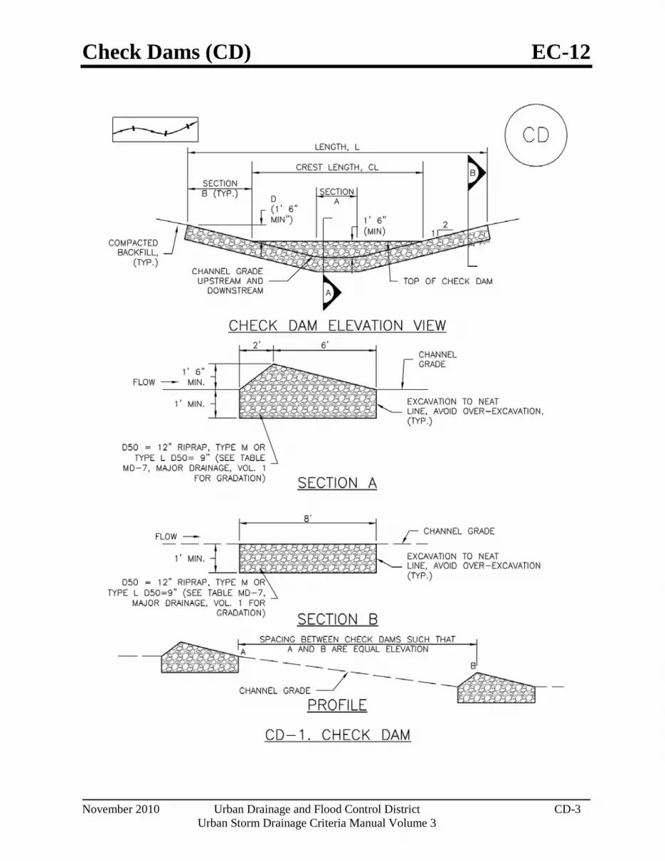
Check Dams (CD) EC-12
November 2010 Urban Drainage and Flood Control District CD-3 Urban Storm Drainage Criteria Manual Volume 3

EC-12 Check Dams (CD)
CD-4 Urban Drainage and Flood Control District November 2010
Urban Storm Drainage Criteria Manual Volume 3

Check Dams (CD) EC-12
November 2010 Urban Drainage and Flood Control District CD-5 Urban Storm Drainage Criteria Manual Volume 3

EC-12 Check Dams (CD)
CD-6 Urban Drainage and Flood Control District November 2010
Urban Storm Drainage Criteria Manual Volume 3

Grand Valley Storage CSWMP (SW22-0041) Page 18 of 18 January 17, 2022
Appendix D
NRCS SOIL INFORMATION

Hydrologic Soil Group—Mesa County Area, Colorado(Grand Valley Storage)
Natural ResourcesConservation Service
Web Soil SurveyNational Cooperative Soil Survey
12/16/2021Page 1 of 4
4334
370
4334
430
4334
490
4334
550
4334
610
4334
670
4334
730
4334
790
4334
850
4334
370
4334
430
4334
490
4334
550
4334
610
4334
670
4334
730
4334
790
4334
850
699030 699090 699150 699210 699270 699330 699390
699030 699090 699150 699210 699270 699330 699390
39° 8' 24'' N10
8° 4
1' 5
0'' W
39° 8' 24'' N
108°
41'
34'
' W
39° 8' 7'' N
108°
41'
50'
' W
39° 8' 7'' N
108°
41'
34'
' W
N
Map projection: Web Mercator Corner coordinates: WGS84 Edge tics: UTM Zone 12N WGS840 100 200 400 600
Feet0 35 70 140 210
MetersMap Scale: 1:2,540 if printed on A portrait (8.5" x 11") sheet.
Soil Map may not be valid at this scale.

MAP LEGEND MAP INFORMATION
Area of Interest (AOI)Area of Interest (AOI)
SoilsSoil Rating Polygons
A
A/D
B
B/D
C
C/D
D
Not rated or not available
Soil Rating LinesA
A/D
B
B/D
C
C/D
D
Not rated or not available
Soil Rating PointsA
A/D
B
B/D
C
C/D
D
Not rated or not available
Water FeaturesStreams and Canals
TransportationRails
Interstate Highways
US Routes
Major Roads
Local Roads
BackgroundAerial Photography
The soil surveys that comprise your AOI were mapped at 1:24,000.
Warning: Soil Map may not be valid at this scale.
Enlargement of maps beyond the scale of mapping can cause misunderstanding of the detail of mapping and accuracy of soil line placement. The maps do not show the small areas of contrasting soils that could have been shown at a more detailed scale.
Please rely on the bar scale on each map sheet for map measurements.
Source of Map: Natural Resources Conservation ServiceWeb Soil Survey URL: Coordinate System: Web Mercator (EPSG:3857)
Maps from the Web Soil Survey are based on the Web Mercator projection, which preserves direction and shape but distorts distance and area. A projection that preserves area, such as the Albers equal-area conic projection, should be used if more accurate calculations of distance or area are required.
This product is generated from the USDA-NRCS certified data as of the version date(s) listed below.
Soil Survey Area: Mesa County Area, ColoradoSurvey Area Data: Version 12, Sep 2, 2021
Soil map units are labeled (as space allows) for map scales 1:50,000 or larger.
Date(s) aerial images were photographed: Jun 24, 2020—Jul 8, 2020
The orthophoto or other base map on which the soil lines were compiled and digitized probably differs from the background imagery displayed on these maps. As a result, some minor shifting of map unit boundaries may be evident.
Hydrologic Soil Group—Mesa County Area, Colorado(Grand Valley Storage)
Natural ResourcesConservation Service
Web Soil SurveyNational Cooperative Soil Survey
12/16/2021Page 2 of 4
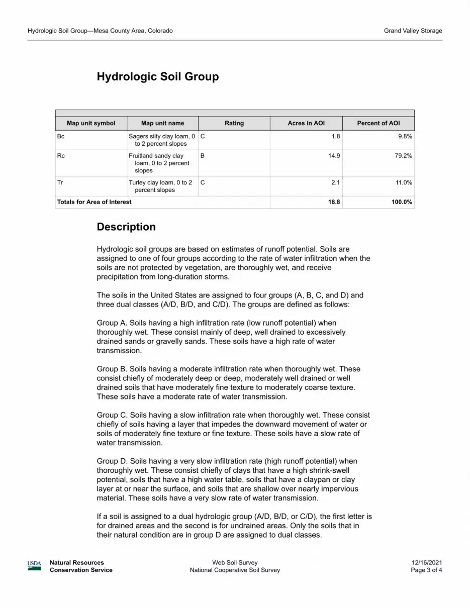
Hydrologic Soil Group
Map unit symbol Map unit name Rating Acres in AOI Percent of AOI
Bc Sagers silty clay loam, 0 to 2 percent slopes
C 1.8 9.8%
Rc Fruitland sandy clay loam, 0 to 2 percent slopes
B 14.9 79.2%
Tr Turley clay loam, 0 to 2 percent slopes
C 2.1 11.0%
Totals for Area of Interest 18.8 100.0%
Description
Hydrologic soil groups are based on estimates of runoff potential. Soils are assigned to one of four groups according to the rate of water infiltration when the soils are not protected by vegetation, are thoroughly wet, and receive precipitation from long-duration storms.
The soils in the United States are assigned to four groups (A, B, C, and D) and three dual classes (A/D, B/D, and C/D). The groups are defined as follows:
Group A. Soils having a high infiltration rate (low runoff potential) when thoroughly wet. These consist mainly of deep, well drained to excessively drained sands or gravelly sands. These soils have a high rate of water transmission.
Group B. Soils having a moderate infiltration rate when thoroughly wet. These consist chiefly of moderately deep or deep, moderately well drained or well drained soils that have moderately fine texture to moderately coarse texture. These soils have a moderate rate of water transmission.
Group C. Soils having a slow infiltration rate when thoroughly wet. These consist chiefly of soils having a layer that impedes the downward movement of water or soils of moderately fine texture or fine texture. These soils have a slow rate of water transmission.
Group D. Soils having a very slow infiltration rate (high runoff potential) when thoroughly wet. These consist chiefly of clays that have a high shrink-swell potential, soils that have a high water table, soils that have a claypan or clay layer at or near the surface, and soils that are shallow over nearly impervious material. These soils have a very slow rate of water transmission.
If a soil is assigned to a dual hydrologic group (A/D, B/D, or C/D), the first letter is for drained areas and the second is for undrained areas. Only the soils that in their natural condition are in group D are assigned to dual classes.
Hydrologic Soil Group—Mesa County Area, Colorado Grand Valley Storage
Natural ResourcesConservation Service
Web Soil SurveyNational Cooperative Soil Survey
12/16/2021Page 3 of 4

Rating Options
Aggregation Method: Dominant Condition
Component Percent Cutoff: None Specified
Tie-break Rule: Higher
Hydrologic Soil Group—Mesa County Area, Colorado Grand Valley Storage
Natural ResourcesConservation Service
Web Soil SurveyNational Cooperative Soil Survey
12/16/2021Page 4 of 4

K Factor, Whole Soil—Mesa County Area, Colorado(Grand Valley Storage)
Natural ResourcesConservation Service
Web Soil SurveyNational Cooperative Soil Survey
12/16/2021Page 1 of 3
4334
370
4334
430
4334
490
4334
550
4334
610
4334
670
4334
730
4334
790
4334
850
4334
370
4334
430
4334
490
4334
550
4334
610
4334
670
4334
730
4334
790
4334
850
699030 699090 699150 699210 699270 699330 699390
699030 699090 699150 699210 699270 699330 699390
39° 8' 24'' N10
8° 4
1' 5
0'' W
39° 8' 24'' N
108°
41'
34'
' W
39° 8' 7'' N
108°
41'
50'
' W
39° 8' 7'' N
108°
41'
34'
' W
N
Map projection: Web Mercator Corner coordinates: WGS84 Edge tics: UTM Zone 12N WGS840 100 200 400 600
Feet0 35 70 140 210
MetersMap Scale: 1:2,540 if printed on A portrait (8.5" x 11") sheet.
Soil Map may not be valid at this scale.

MAP LEGEND MAP INFORMATION
Area of Interest (AOI)Area of Interest (AOI)
SoilsSoil Rating Polygons
.02
.05
.10
.15
.17
.20
.24
.28
.32
.37
.43
.49
.55
.64
Not rated or not available
Soil Rating Lines.02
.05
.10
.15
.17
.20
.24
.28
.32
.37
.43
.49
.55
.64
Not rated or not available
Soil Rating Points.02
.05
.10
.15
.17
.20
.24
.28
.32
.37
.43
.49
.55
.64
Not rated or not available
Water Features
Streams and Canals
TransportationRails
Interstate Highways
US Routes
Major Roads
Local Roads
BackgroundAerial Photography
The soil surveys that comprise your AOI were mapped at 1:24,000.
Warning: Soil Map may not be valid at this scale.
Enlargement of maps beyond the scale of mapping can cause misunderstanding of the detail of mapping and accuracy of soil line placement. The maps do not show the small areas of contrasting soils that could have been shown at a more detailed scale.
Please rely on the bar scale on each map sheet for map measurements.
Source of Map: Natural Resources Conservation ServiceWeb Soil Survey URL: Coordinate System: Web Mercator (EPSG:3857)
Maps from the Web Soil Survey are based on the Web Mercator projection, which preserves direction and shape but distorts distance and area. A projection that preserves area, such as the Albers equal-area conic projection, should be used if more accurate calculations of distance or area are required.
This product is generated from the USDA-NRCS certified data as of the version date(s) listed below.
Soil Survey Area: Mesa County Area, ColoradoSurvey Area Data: Version 12, Sep 2, 2021
Soil map units are labeled (as space allows) for map scales 1:50,000 or larger.
Date(s) aerial images were photographed: Jun 24, 2020—Jul 8, 2020
The orthophoto or other base map on which the soil lines were compiled and digitized probably differs from the background imagery displayed on these maps. As a result, some minor shifting of map unit boundaries may be evident.
K Factor, Whole Soil—Mesa County Area, Colorado(Grand Valley Storage)
Natural ResourcesConservation Service
Web Soil SurveyNational Cooperative Soil Survey
12/16/2021Page 2 of 3

K Factor, Whole Soil
Map unit symbol Map unit name Rating Acres in AOI Percent of AOI
Bc Sagers silty clay loam, 0 to 2 percent slopes
.43 1.8 9.8%
Rc Fruitland sandy clay loam, 0 to 2 percent slopes
.17 14.9 79.2%
Tr Turley clay loam, 0 to 2 percent slopes
.28 2.1 11.0%
Totals for Area of Interest 18.8 100.0%
Description
Erosion factor K indicates the susceptibility of a soil to sheet and rill erosion by water. Factor K is one of six factors used in the Universal Soil Loss Equation (USLE) and the Revised Universal Soil Loss Equation (RUSLE) to predict the average annual rate of soil loss by sheet and rill erosion in tons per acre per year. The estimates are based primarily on percentage of silt, sand, and organic matter and on soil structure and saturated hydraulic conductivity (Ksat). Values of K range from 0.02 to 0.69. Other factors being equal, the higher the value, the more susceptible the soil is to sheet and rill erosion by water.
"Erosion factor Kw (whole soil)" indicates the erodibility of the whole soil. The estimates are modified by the presence of rock fragments.
Factor K does not apply to organic horizons and is not reported for those layers.
Rating Options
Aggregation Method: Dominant Condition
Component Percent Cutoff: None Specified
Tie-break Rule: Higher
Layer Options (Horizon Aggregation Method): Surface Layer (Not applicable)
K Factor, Whole Soil—Mesa County Area, Colorado Grand Valley Storage
Natural ResourcesConservation Service
Web Soil SurveyNational Cooperative Soil Survey
12/16/2021Page 3 of 3