common aerospace applications at dlr utilizing the overset grid capabilities of dlr's cfd codes
TRANSCRIPT
Common Aerospace Applications at DLR Utilizing
the Overset Grid Capabilites of DLR’s CFD Codes
L. Reimer, Th. Schwarz, A. Raichle, R. Heinrich,
F. Spiering, A. Stürmer, S. Crippa, Ph. Kelleners,
N. Bier, G. Einarsson, N. Kroll
www.DLR.de • Chart 1
11th Overset Grid Symposium
October 15th-18th, 2012
Dayton, Ohio, USA
> Overset Grid Capabilities of DLR’s CFD Codes > L.Reimer et al. • OGS 2012 > October 15th-18th, 2012
German Aerospace Center
Institute of Aerodynamics and Flow Technology
Departments „Transport Aircraft“ & C²A²S²E
Braunschweig, Germany

Outline
www.DLR.de • Chart 2 > Overset Grid Capabilities of DLR’s CFD Codes > L.Reimer et al. • OGS 2012 > October 15th-18th, 2012
• Methodology
• DLR‘s solvers w/ overset grid capabilities
• Our hole-cutting approaches
• Chimera wall projection
• Load integration
• Applications
• CFD-6DoF
• CROR
• Helicopters
• Control surface motion
• Local discretisation improvement
• Code-to-code coupling

Methodology
www.DLR.de • Chart 3 > Overset Grid Capabilities of DLR’s CFD Codes > L.Reimer et al. • OGS 2012 > October 15th-18th, 2012

DLR‘s CFD Solvers w/ Overset Grid Capabilities
www.DLR.de • Chart 4 > Overset Grid Capabilities of DLR’s CFD Codes > L.Reimer et al. • OGS 2012 > October 15th-18th, 2012
Special to TAU:
• Work horse of Airbus for aerodynamics analysis
on unstructured meshes
• Python interfaces => scripting, in-memory data
exchange (6DoF, CFD-CSM coupl.)
• Feature & adjoint-based adaptation
Multiblock-structured
compressible RANS
solver FLOWer
Common to both solvers:
• Developments started in mid 1990s
• FV, 2nd order accuray in space & time
• ALE capability
• Moving, deforming meshes
• Turbulence models: 1-eqn. SA variants, 2-eqn.
k-ω-type models, EARSM, RSM; DES, LES
• Fluxes: Central+scalar/matrix diss., Upwinding
• Steady time int.: RK (FLOWer/TAU),
LU-SGS, line-implicit (TAU) + multigrid
• Unsteady time int.: Dual-time stepping
• Hybrid MPI/OpenMP-based parallelisation
Unstructured
compressible RANS
solver TAU

Our Overset Grid Interpolation Technique
www.DLR.de • Chart 5 > Overset Grid Capabilities of DLR’s CFD Codes > L.Reimer et al. • OGS 2012 > October 15th-18th, 2012
• Parallel donor search integrated directly in solver loop (no external tool,
no file I/O); 2-stage search
1. ADT-based search
2. Iso-parametric mapping based search
• Interpolation is based on primary mesh cells using FE shape functions
• Only 4 different FE shape functions need to be considered
• Dual mesh contains arbitrary polyhedrons which would make
interpolation more complex & expensive
• Interpolation takes place only on finest multigrid level
• 2 fringe layers

www.DLR.de • Chart 6 > Overset Grid Capabilities of DLR’s CFD Codes > L.Reimer et al. • OGS 2012 > October 15th-18th, 2012
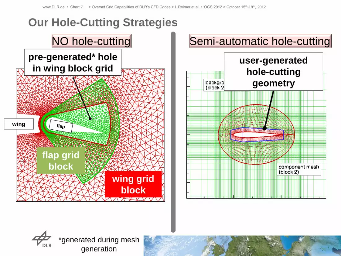
Our Hole-Cutting Strategies
wing
wing grid
block
flap grid
block
pre-generated* hole
in wing block grid user-generated
hole-cutting
geometry
NO hole-cutting Semi-automatic hole-cutting
*generated during mesh
generation
www.DLR.de • Chart 7 > Overset Grid Capabilities of DLR’s CFD Codes > L.Reimer et al. • OGS 2012 > October 15th-18th, 2012
Our Hole-Cutting Strategies
wing
wing grid
block
flap grid
block
pre-generated* hole
in wing block grid
NO hole-cutting
user-generated
hole-cutting
geometry
Semi-automatic hole-cutting
*generated during mesh
generation

www.DLR.de • Chart 9 > Overset Grid Capabilities of DLR’s CFD Codes > L.Reimer et al. • OGS 2012 > October 15th-18th, 2012
Our Hole-Cutting Strategies
wing
wing grid
block
flap grid
block
pre-generated* hole
in wing block grid
NO hole-cutting Semi-automatic hole-cutting
*generated during mesh
generation

www.DLR.de • Chart 10 > Overset Grid Capabilities of DLR’s CFD Codes > L.Reimer et al. • OGS 2012 > October 15th-18th, 2012
Our Hole-Cutting Strategies
hole-cutting geometry
rigidly rotated with
grid block
wing
wing grid
block
flap grid
block
pre-generated* hole
in wing block grid
NO hole-cutting Semi-automatic hole-cutting
*generated during mesh
generation

www.DLR.de • Chart 11 > Overset Grid Capabilities of DLR’s CFD Codes > L.Reimer et al. • OGS 2012 > October 15th-18th, 2012
Our Hole-Cutting Strategies
blanking recomputed
from rotated hole-
cutting geo
wing
wing grid
block
flap grid
block
pre-generated* hole
in wing block grid
NO hole-cutting Semi-automatic hole-cutting
*generated during mesh
generation
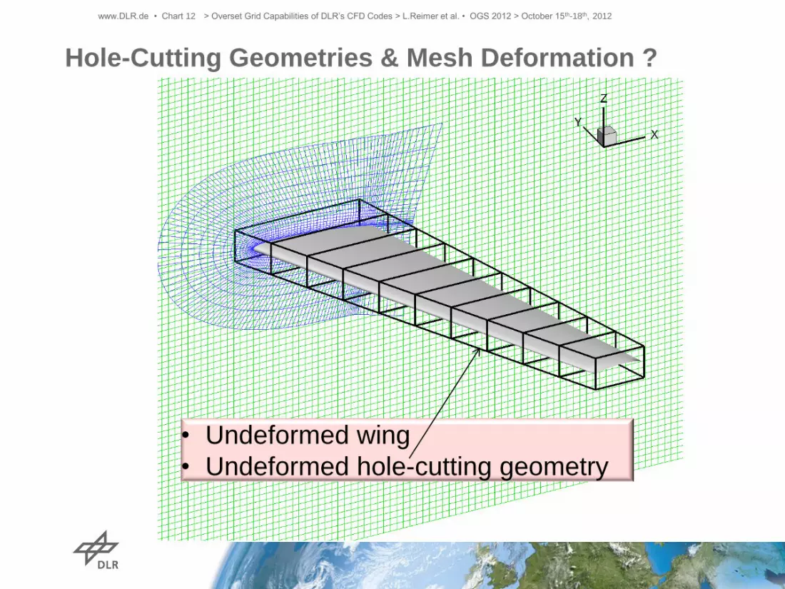
Hole-Cutting Geometries & Mesh Deformation ?
www.DLR.de • Chart 12 > Overset Grid Capabilities of DLR’s CFD Codes > L.Reimer et al. • OGS 2012 > October 15th-18th, 2012
• Undeformed wing
• Undeformed hole-cutting geometry

Hole-Cutting Geometries & Mesh Deformation ?
www.DLR.de • Chart 13 > Overset Grid Capabilities of DLR’s CFD Codes > L.Reimer et al. • OGS 2012 > October 15th-18th, 2012
• Deformed wing
• Undeformed hole-cutting geometry
→ Chimera interpolation will fail
because of orphan points !

www.DLR.de • Chart 14 > Overset Grid Capabilities of DLR’s CFD Codes > L.Reimer et al. • OGS 2012 > October 15th-18th, 2012
Hole-Cutting Geometries & Mesh Deformation ?
• Deformed wing
• Deformed hole-cutting geometry
→ Chimera interpolation works !
Solution: Mesh deformation operator used for overset
grids is also to be applied to hole-cutting geometries

Overlapping Surface Meshes:
Problem Description
www.DLR.de • Chart 15 > Overset Grid Capabilities of DLR’s CFD Codes > L.Reimer et al. • OGS 2012 > October 15th-18th, 2012
Point outside
of donor grid
d1 d2
Different
discretizations
along curved
surfaces
CAD
descrepancies
Wrong wall distance
www.DLR.de • Chart 16 > Overset Grid Capabilities of DLR’s CFD Codes > L.Reimer et al. • OGS 2012 > October 15th-18th, 2012
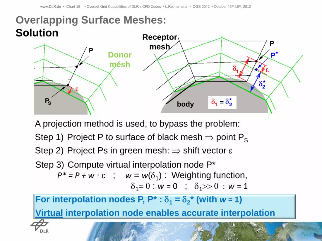
Step 3) Compute virtual interpolation node P* P* = P + w ∙ e ; w = w(d1) : Weighting function,
d1= 0 : w = 0 ; d1>> 0 : w = 1
For interpolation nodes P, P* : d1 = d2* (with w = 1)
Virtual interpolation node enables accurate interpolation
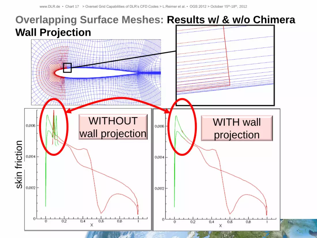
A projection method is used, to bypass the problem:
Step 1) Project P to surface of black mesh point PS
Step 2) Project Ps in green mesh: shift vector e
body
Overlapping Surface Meshes:
Solution
Donor
mesh
Receptor
mesh
www.DLR.de • Chart 17 > Overset Grid Capabilities of DLR’s CFD Codes > L.Reimer et al. • OGS 2012 > October 15th-18th, 2012
Overlapping Surface Meshes: Results w/ & w/o Chimera
Wall Projection
WITHOUT
wall projection WITH wall
projection
skin
fri
ctio
n
www.DLR.de • Chart 18 > Overset Grid Capabilities of DLR’s CFD Codes > L.Reimer et al. • OGS 2012 > October 15th-18th, 2012
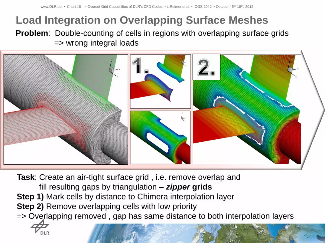
Load Integration on Overlapping Surface Meshes
Task: Create an air-tight surface grid , i.e. remove overlap and
fill resulting gaps by triangulation – zipper grids
Step 1) Mark cells by distance to Chimera interpolation layer
Step 2) Remove overlapping cells with low priority
=> Overlapping removed , gap has same distance to both interpolation layers
Problem: Double-counting of cells in regions with overlapping surface grids
=> wrong integral loads

www.DLR.de • Chart 19 > Overset Grid Capabilities of DLR’s CFD Codes > L.Reimer et al. • OGS 2012 > October 15th-18th, 2012
Load Integration on Overlapping Surface Meshes
Task: Create a air-tight surface grid = Remove overlap and
fill gaps by triangulation – zipper grids
Step 3) Extract border lines of resulting grids
Step 4) Gather opposing border lines to build gap data that is to be triangulated
Problem: Double-counting of cells in regions with overlapping surface grids
=> wrong integral loads

www.DLR.de • Chart 20 > Overset Grid Capabilities of DLR’s CFD Codes > L.Reimer et al. • OGS 2012 > October 15th-18th, 2012
Load Integration on Overlapping Surface Meshes
i
i i
iii SSpF
=
Task: Create a air-tight surface grid = Remove overlap and
fill gaps by triangulation – zipper grids
Step 5) Delaunay triangulation
Step 6) Force summation on non-overlapping grid In the past: Only available
as sequential postproc. tool
Now: Parallel version
directly integrated into TAU
Problem: Double-counting of cells in regions with overlapping surface grids
=> wrong integral loads

www.DLR.de • Chart 21 > Overset Grid Capabilities of DLR’s CFD Codes > L.Reimer et al. • OGS 2012 > October 15th-18th, 2012
Cartesian Background
Grid Generator
Problem: Manual generation
of background grid with
sufficient overlap & resolution
cumbersome and time-
consuming
Idea: Automatic generation
of Cartesian multiblock
grids with hanging nodes
(only FLOWer; TAU does
not feature hanging nodes
capability yet)

www.DLR.de • Chart 22 > Overset Grid Capabilities of DLR’s CFD Codes > L.Reimer et al. • OGS 2012 > October 15th-18th, 2012
Cartesian Background
Grid Generator
user-generated
nearfield grids
background grid with
anisotropic cells
Features:
• Very coarse initial
background grids (8x8x8
cells) are adapted
consecutively to the
nearfield grid‘s cell sizes
• Anisotropic refinements
possible
=> Reduction of
interpolation errors
=> Prevents from
insufficient cell overlap
• Minimisation of the number
of blocks by automatic
concatenation
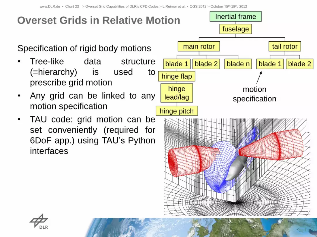
Overset Grids in Relative Motion
www.DLR.de • Chart 23 > Overset Grid Capabilities of DLR’s CFD Codes > L.Reimer et al. • OGS 2012 > October 15th-18th, 2012
Specification of rigid body motions
• Tree-like data structure
(=hierarchy) is used to
prescribe grid motion
• Any grid can be linked to any
motion specification
• TAU code: grid motion can be
set conveniently (required for
6DoF app.) using TAU’s Python
interfaces
Inertial frame
hinge pitch
hinge flap
blade 2
tail rotor
hinge
lead/lag
blade 1 blade 1
main rotor
blade 2 blade n
fuselage
motion
specification

Applications
www.DLR.de • Chart 24 > Overset Grid Capabilities of DLR’s CFD Codes > L.Reimer et al. • OGS 2012 > October 15th-18th, 2012

www.DLR.de • Chart 25 > Overset Grid Capabilities of DLR’s CFD Codes > L.Reimer et al. • OGS 2012 > October 15th-18th, 2012
MiTraPor
• Measurement of location of
generic boxes w/ and w/o
parachute
• Flow conditions:
vinf = 18m/s, a = 6°, Re =4x10⁵
PUR (2,5t) a = 0 deg b = 0 deg u 0 = 20 m/s
LINDE (1,5t) a = 0 deg b = 0 deg u 0 = 20 m/s
PUR (2,5t) a = 0 deg b = 0 deg u 0 = 20 m/s
LINDE (1,5t) a = 0 deg b = 0 deg u 0 = 20 m/s
PUR (2,5t) a = 0 deg b = 0 deg u 0 = 20 m/s
LINDE (1,5t) a = 0 deg b = 0 deg u 0 = 20 m/s
PUR (2,5t) a = 0 deg b = 0 deg u 0 = 20 m/s
Coupled CFD-6DoF Simulation of Airdrop Scenario
MiTraPor Test Case Example airdrop: MiTraPor airdrop:
http://www.youtube.com/watch?v=eQwJnVad5L4

Coupled CFD-6DoF Simulation of Airdrop Scenario
MiTraPor Test Case
www.DLR.de • Chart 26 > Overset Grid Capabilities of DLR’s CFD Codes > L.Reimer et al. • OGS 2012 > October 15th-18th, 2012
MiTraPor
• Making use of overset grid
technique with semi-automatic
hole cutting
• Unstruct. background A/C
mesh
• Unstruct. mesh around
parachute-box config.
• Tight coupling of TAU to 6DoF
code user-generated hole-
cutting geometries
parachute-box
connection disreg.
A/C mesh,
27M nodes
parachute-
box mesh,
2.3M nodes
Refinement along
expected flight path
Computational setup:

www.DLR.de • Chart 28 > Overset Grid Capabilities of DLR’s CFD Codes > L.Reimer et al. • OGS 2012 > October 15th-18th, 2012
MiTraPor
Coupled
CFD-6DoF
Sim. of
Airdrop
Scenario
Computing time:
42.6M pts., 144 procs:
160h (~7d) for 0.33s
real time, 53min per
phys. time step @
600Hz resol.

www.DLR.de • Chart 29 > Overset Grid Capabilities of DLR’s CFD Codes > L.Reimer et al. • OGS 2012 > October 15th-18th, 2012
Zg
Xg
Time [s]
Z_
ge
od
[m]
X_
ge
od
[m]
0 0.05 0.1 0.15 0.2 0.25 0.3 0.35 0.4 0.450.0
00
0.5
00
1.0
00
1.5
00
-1.0
0-0
.50
0.0
00
.50
FMTA - Last B
Re = 0.4e06 / U = 18 m/s / AoA = 06 deg
Solid: simulation
Dashed: experiment
Solid: simulation
Dashed: experiment
T i m e [ s ]
V _
z g
[ m
/ s ]
V _
x g
[ m
/ s ]
0 0 . 0 5 0 . 1 0 . 1 5 0 . 2 0 . 2 5 0 . 3
0 . 5
1
. 0
1 . 5
2
. 0
2 . 5
3
. 0
3 . 5
- 4 . 0
- 3
. 5
- 3 . 0
- 2
. 5
- 2 . 0
- 1
. 5
- 1 . 0
- 0
. 5
0 . 0
F M T A - L a s t B
R e = 0 . 4 e 0 6 / U = 1 8 m / s / A o A = 0 6 d e g
Positions
Velocities
MiTraPor
Coupled CFD-6DoF Simulation of
Airdrop Scenario:
MiTraPor Test Case – Comparison of
Computed & Measured Trajectories

www.DLR.de • Chart 30 > Overset Grid Capabilities of DLR’s CFD Codes > L.Reimer et al. • OGS 2012 > October 15th-18th, 2012
Coupled CFD-6DoF Sim.
of Store Release
AFRL* Test Case
• Activity within GARTEUR SIG 47
• Flow conditions: Ma = 0.95,
a = 0.0°, Re = 4.1m
• Experiment conducted by AFRL,
see RTO-TR-26, ch. 23
• Meshes:
• Store: Structured Ansys
ICEM-CFD HEXA Navier-
Stokes mesh converted to
TAU format, 3.1M nodes
• Delta wing: Unstructured
CentaurSoft Centaur Euler
mesh, 600k nodes
* Air Force Research Laboratory, Wright-Patterson Air Force Base
Hole-cutting geometries

www.DLR.de • Chart 31 > Overset Grid Capabilities of DLR’s CFD Codes > L.Reimer et al. • OGS 2012 > October 15th-18th, 2012
Coupled CFD-6DoF Sim. of Store Release
AFRL Test Case
Difficulty:
At t=0 store & pylon are
very close

www.DLR.de • Chart 32 > Overset Grid Capabilities of DLR’s CFD Codes > L.Reimer et al. • OGS 2012 > October 15th-18th, 2012
Coupled CFD-6DoF Sim. of Store Release
AFRL Test Case
ORPHAN POINTS
Difficulty:
At t=0 store & pylon are
very close => With the
original mesh, not all donor
cells could be found

www.DLR.de • Chart 33 > Overset Grid Capabilities of DLR’s CFD Codes > L.Reimer et al. • OGS 2012 > October 15th-18th, 2012
Coupled CFD-6DoF Sim. of Store Release
AFRL Test Case
Difficulty:
At t=0 store & pylon are
very close => With the
original mesh, not all donor
cells could be found
Approach for solving the
problem:
Uniform adaptation of the
delta wing mesh
• … close to the pylon
• … in expected flight
path area

www.DLR.de • Chart 34 > Overset Grid Capabilities of DLR’s CFD Codes > L.Reimer et al. • OGS 2012 > October 15th-18th, 2012
Coupled CFD-6DoF Sim. of Store Release
AFRL Test Case
Difficulty:
At t=0 store & pylon are
very close => With the
original mesh, not all donor
cells could be found
Approach for solving the
problem:
Uniform adaptation of the
delta wing mesh
• … close to the pylon
• … in expected flight
path area
With adaptation
approach the
simulation worked
www.DLR.de • Chart 35 > Overset Grid Capabilities of DLR’s CFD Codes > L.Reimer et al. • OGS 2012 > October 15th-18th, 2012
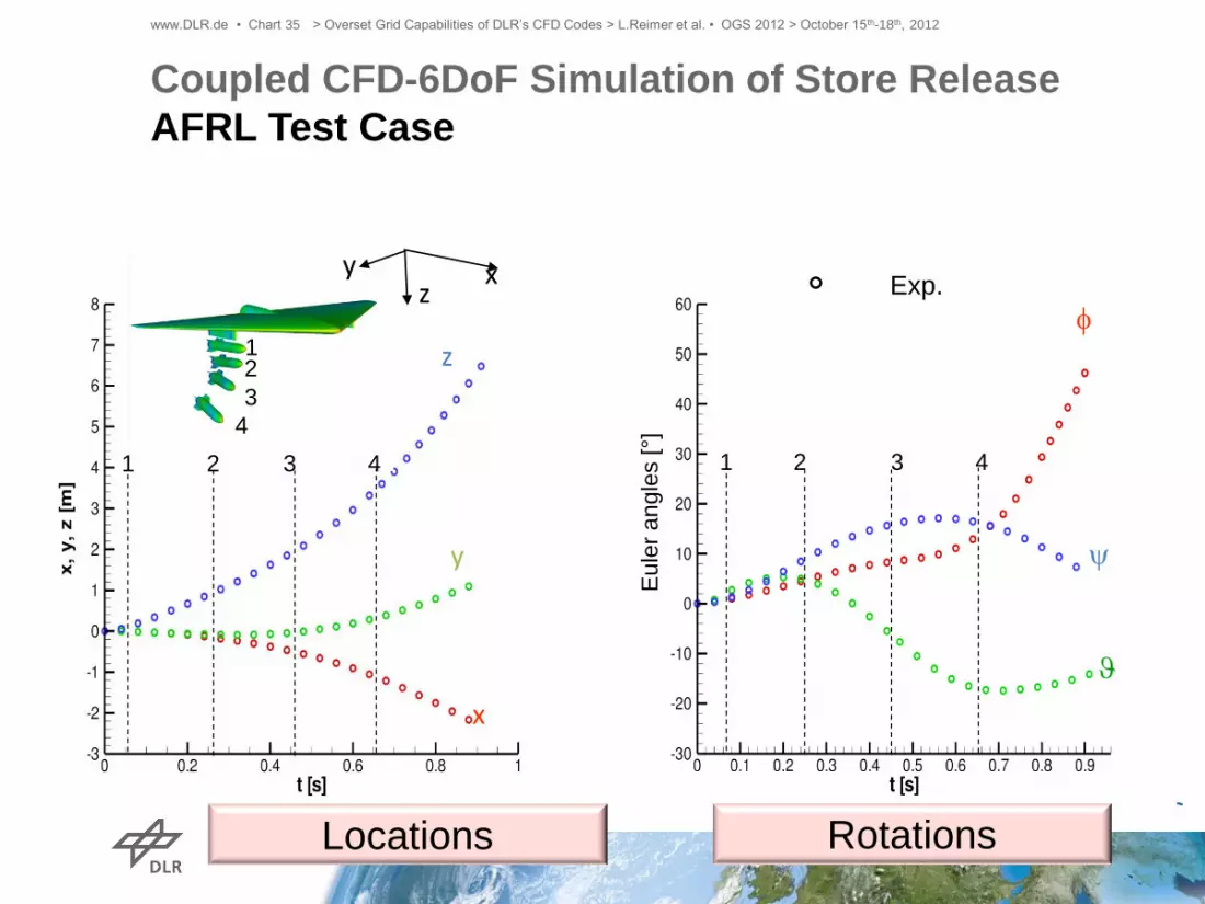
Coupled CFD-6DoF Simulation of Store Release
AFRL Test Case
Eu
ler
an
gle
s [°]
z
y
x
1 2
3
4
z y x
1 2 3 4 1 2 3 4
Exp.
f
y
Locations Rotations

www.DLR.de • Chart 36 > Overset Grid Capabilities of DLR’s CFD Codes > L.Reimer et al. • OGS 2012 > October 15th-18th, 2012
1 2
3
4
z y x
1 2 3 4
Eu
ler
an
gle
s [°]
1 2 3 4
z
y
x
DLR Exp.
f
y
Coupled CFD-6DoF Simulation of Store Release
AFRL Test Case DLR‘s simulation:
• Strong coupling of CFD-6DoF (unsteady)
• SA turb. model
Locations Rotations

www.DLR.de • Chart 37 > Overset Grid Capabilities of DLR’s CFD Codes > L.Reimer et al. • OGS 2012 > October 15th-18th, 2012
1 2
3
4
z y x
1 2 3 4
Eu
ler
an
gle
s [°]
1 2 3 4
z
y
x
DLR ONERA
Exp.
f
y
Coupled CFD-6DoF Simulation of Store Release
AFRL Test Case DLR‘s simulation:
• Strong CFD-6DoF coupling (unsteady)
• SA turb. model
ONERA‘s simulation:
• Quasi-steady coupling CFD-6DoF
• SA turb. model
Locations Rotations

Open Rotor Applications:
CROR Flow Analysis
www.DLR.de • Chart 38 > Overset Grid Capabilities of DLR’s CFD Codes > L.Reimer et al. • OGS 2012 > October 15th-18th, 2012
19-21 overset grid blocks
pre-
generated
holes
Here: Isolated rotor case
• Unstruct. background grid, struct.
spinner & blade grids, „pre-
generated“ holes used

Open Rotor Applications:
CROR Flow Analysis
www.DLR.de • Chart 39 > Overset Grid Capabilities of DLR’s CFD Codes > L.Reimer et al. • OGS 2012 > October 15th-18th, 2012
19-21 overset grid blocks
pre-
generated
holes
Here: Isolated rotor case
• Unstruct. background grid, struct.
spinner & blade grids, „pre-
generated“ holes used
• Perform. & noise analysis of many
config. variations

Open Rotor Applications:
CROR Flow Analysis
www.DLR.de • Chart 40 > Overset Grid Capabilities of DLR’s CFD Codes > L.Reimer et al. • OGS 2012 > October 15th-18th, 2012
19-21 overset grid blocks
pre-
generated
holes
Here: Isolated rotor case
• Unstruct. background grid, struct.
spinner & blade grids, „pre-
generated“ holes used
• Perform. & noise analysis of many
config. variations

Open Rotor Applications:
CROR Flow Analysis
www.DLR.de • Chart 41 > Overset Grid Capabilities of DLR’s CFD Codes > L.Reimer et al. • OGS 2012 > October 15th-18th, 2012
CFD(+CSM)-
based blade
loads
analysis
19-21 overset grid blocks
Here: Isolated rotor case
• Unstruct. background grid, struct.
spinner & blade grids, „pre-
generated“ holes used
• Perform. & noise analysis of many
config. variations
• Comp. time: 65M nodes case,
360 procs..: 720 timesteps per
revolution necessary => ~4d per rev;
6-12 revs necessary => ~1.5-3 weeks

Open Rotor Applications:
CROR Flow Analysis
www.DLR.de • Chart 42 > Overset Grid Capabilities of DLR’s CFD Codes > L.Reimer et al. • OGS 2012 > October 15th-18th, 2012
19-21 overset
grid blocks
CFD-based
airframe
loads
analysis
Here: Integrated rotor case
• Unstruct. background grid, struct.
spinner & blade grids, „pre-
generated“ holes used

Helicopter Applications:
BO105 Case
www.DLR.de • Chart 43 > Overset Grid Capabilities of DLR’s CFD Codes > L.Reimer et al. • OGS 2012 > October 15th-18th, 2012
W/T
model
afuselage = -5.2
M = 0.1766
MMR = 0.652
MTR = 0.63
QMR = 10.5° - 6.3° sin(Y)
+ 1.9° cos(Y)
QTR = 8.0°
CFD model
Component grids are
embedded in Cartesian
background grid with
hanging nodes
horizontal stabilizer
main rotor and tail rotor
fuselage
spoiler and strut
skids
Nearfield SMB grids for
Total: 480 blocks,
11.8m nodes

Helicopter Applications:
BO105 Case
www.DLR.de • Chart 44 > Overset Grid Capabilities of DLR’s CFD Codes > L.Reimer et al. • OGS 2012 > October 15th-18th, 2012
λ2 iso-surfaces
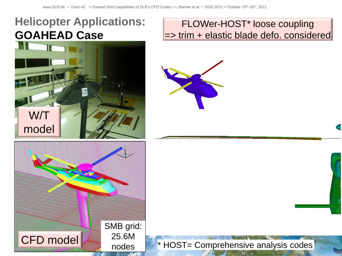
Helicopter Applications:
GOAHEAD Case
www.DLR.de • Chart 45 > Overset Grid Capabilities of DLR’s CFD Codes > L.Reimer et al. • OGS 2012 > October 15th-18th, 2012
SMB grid:
25.6M
nodes
W/T
model
CFD model
FLOWer-HOST* loose coupling
=> trim + elastic blade defo. considered
* HOST= Comprehensive analysis codes

www.DLR.de • Chart 46 > Overset Grid Capabilities of DLR’s CFD Codes > L.Reimer et al. • OGS 2012 > October 15th-18th, 2012
gaps gaps
gaps
Control Surface (CS) Motions
• Meshing & sim. of configs.
with statically deflected CS
is standard application
• Though it still challenging
consideration of moving CS
becomes more important (e.g.
analysis of maneuver loads &
effectiveness of gust load
alleviation systems)
• Main issue: Gap handling
2 Approaches:
• Chimera-only: Rotating
Chimera block
• Chimera+Mesh defo.:
Fixed Chimera block
(seems most promising)
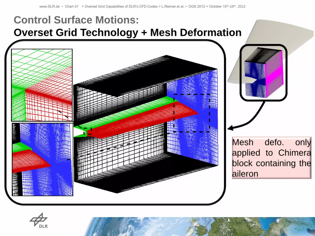
www.DLR.de • Chart 47 > Overset Grid Capabilities of DLR’s CFD Codes > L.Reimer et al. • OGS 2012 > October 15th-18th, 2012
Control Surface Motions:
Overset Grid Technology + Mesh Deformation
Mesh defo. only
applied to Chimera
block containing the
aileron

Local Discretisation Improvements
Example from DPW-4
www.DLR.de • Chart 48 > Overset Grid Capabilities of DLR’s CFD Codes > L.Reimer et al. • OGS 2012 > October 15th-18th, 2012
Outer boundary of near-
body prism/hexahedra
layer
• Boundary layer in
wing/HTP-fuselage
junction of
inappropriate quality
• Flow separations
might not be
detected at all or are
metric driven

Local Discretisation Improvements
Example from DPW-4
www.DLR.de • Chart 49 > Overset Grid Capabilities of DLR’s CFD Codes > L.Reimer et al. • OGS 2012 > October 15th-18th, 2012
Outer boundary of near-
body prism/hexahedra
layer
• Boundary layer in
wing/HTP-fuselage
junction of
inappropriate quality
• Flow separations
might not be
detected at all or are
metric driven
• Discretisation can be
improved locally by
inserting a structure
Chimera grid

Local Discretisation
Improvements
Example from DPW-4
www.DLR.de • Chart 52 > Overset Grid Capabilities of DLR’s CFD Codes > L.Reimer et al. • OGS 2012 > October 15th-18th, 2012
Original
SOLAR
mesh
Original
SOLAR
mesh
+
Chimera
„glove“
meshes
streamlines Eddy viscosity

Code-to-Code Coupling:
TAU-TRACE
www.DLR.de • Chart 53 > Overset Grid Capabilities of DLR’s CFD Codes > L.Reimer et al. • OGS 2012 > October 15th-18th, 2012
TAU
geo.
TRACE‘s
coupling
interface
TAU‘s
coupling
interface
TRACE geo
TAU TRACE
• TRACE:
• DLR‘s turbomachinery
CFD code
• Multi-block-structured
• cell-centered code
(TAU: node-centered)
• Objective: Flow simulation of a
stalling nacelle including entry of
the separated flow into the engine
fan
• Requires accurate flow prediction of
both external flow and flow inside
engine fan
• Coupling controlled by
socket communication layer
• Spatial coupling with
Chimera

www.DLR.de • Chart 54 > Overset Grid Capabilities of DLR’s CFD Codes > L.Reimer et al. • OGS 2012 > October 15th-18th, 2012
Code-to-Code Coupling:
TAU-Cartesian TAU
Problem: 2nd order spatial accuracy
too dissipative for accurate
computation of convection of gusts or
wake vortices
Solution: Coupling of higher-order
Cartesian solver (CTAU) to 2nd order
solver (TAU)
Cartesian TAU:
• ≥ 4th order spatially accurate
(Pade scheme)
• very coarse Cartesian meshes,
easy to generate
Conventional TAU:
• 2nd order spatially accurate
• fine body-fitted hybrid meshes
Coupling: overset grid interpolation
Example:
Ehrenfried vortex
2nd order central
4th order Pade Concept:
Conclusions
www.DLR.de • Chart 55 > Overset Grid Capabilities of DLR’s CFD Codes > L.Reimer et al. • OGS 2012 > October 15th-18th, 2012
• DLR‘s CFD solvers are very mature, feature standard Chimera
capabilities and are thus applicable to wide range of industrially-
relevant configurations that need Chimera
• Our current major problem:
• Too many manual operations needed to setup Chimera cases
• Lack of toolkits like CGT, etc., at DLR
• High demand for a more „automated“ Chimera case setup process
• Since there is now a fast growing spectrum of applications that rely on
the Chimera technique (Digital-X project: -> virtual flight testing), we
currently increase our effort to bring forward our Chimera capabilities
(e.g. overlap optimization, overlap adaptation, further development of
CTAU solver, …)