combined shear/compression structural testing of asymmetric sandwich structures
TRANSCRIPT

Combined Shear/Compression Structural Testing ofAsymmetric Sandwich Structures
by B. Castanié, J.J. Barrau, J.P. Jaouen and S. Rivallant
ABSTRACT—Asymmetric sandwich technology can be ap-plied in the design of lightweight, non-pressurized aeronauti-cal structures such as those of helicopters. A test rig of asym-metric sandwich structures subjected to compression/shearloads was designed, validated, and set up. It conforms to thestandard certification procedure for composite aeronauticalstructures set out in the “test pyramid”, a multiscale approach.The static tests until failure showed asymmetric sandwichstructures to be extremely resistant, which, in the case of thetested specimen shape, were characterized by the absenceof buckling and failure compressive strains up to 10,000 µstrains. Specimens impacted with perforation damage werealso tested, enabling the original phenomenon of crack prop-agation to be observed step-by-step. The results of the com-pleted tests thus enable the concept to be validated, and jus-tify the possibility of creating a much larger machine to over-come the drawbacks linked to the use of small specimens.
KEY WORDS—Composite sandwich structures, shear/compression testing
Introduction
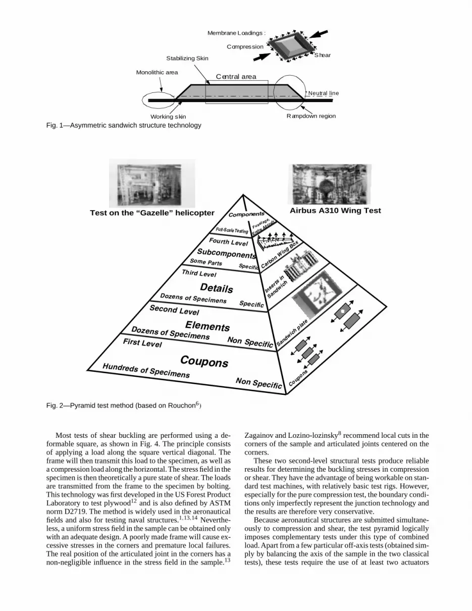
Asymmetric sandwich structures are a new technologyapplicable in the making of light aeronautical structures. Anasymmetric structure differs from a conventional sandwichstructure in its geometry and design. As shown in Fig. 1, sucha structure has three distinct zones: a thick, monolithic zonewith a bolted junction, a tapered transition zone, and finallythe purely asymmetric sandwich composed of a relativelythick skin called “the working skin” and a second skin, the“stabilizing skin”, which is always thin. For the aeronauticalapplications studied, the skins and the monolithic zone aremade of graphite-epoxy laminates and the sandwich core ofNomex Honeycomb. The stabilizing skin is made up of justtwo layers of carbon fibers.
Unlike conventional sandwich structures, this type ofstructure is not well suited to taking bending loads but itcan be used in the making of light aeronautical structuresfor helicopters, light aircraft, etc. These structures thus takeonly membrane-type loads via the working skin. The coreand the stabilizing skin ensure buckling stability under the
B. Castanié ([email protected]) is an Assistant Professor andS. Rivallant is a PhD, Institut de Génie Mécanique de Toulouse(I.G.M.T.)/Supaero Laboratoire Structures, BP 4032 31055 Toulouse,France. J.J. Barrau is a Professor, I.G.M.T./Université Paul Sabatier, Bat3PN, 31062 Toulouse, France. J.P. Jaouen is an Engineer, EurocopterFrance, 13700 Marignane, France.
Original manuscript submitted: July 17, 2003.Final manuscript received: July 6, 2004.DOI: 10.1177/0014485104047607
dimensioning loads of compression and shear. Because theneutral surface of the sandwich is not the same as the loadapplication plane (mid-plane of the working skin), a ten-sile/compression loading also generates a bending moment,which is very sensitive to the deflection of the sandwich. Thismeans that the behavior of this type of structure is geometri-cally nonlinear.1,2 Few, if any, studies of this type of structureexist3 except in the linear field.4
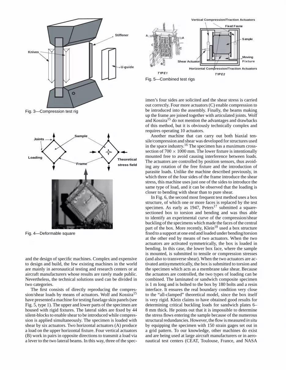
Like all aeronautical structures, the certification of asym-metric sandwich structures depends on a series of tests. Incomposite structures, since “the material is not pre-existentto the part itself”, a multilevel approach is necessary.5 Thistype of approach, first used for metal aeronautic structures, isset out in a “test pyramid” in Europe6 (see Fig. 2). At the baseof the pyramid are the conventional tests of the characteri-zation of materials on the scale of the ply. The second leveltests structure-type specimens, representing the technologyto be qualified but not specific to a particular zone or aircraft.At the upper levels are tests of technological details specificto a zone or an aircraft (junction, windows, etc.), tests ofsubassemblies (spars, wing boxes, etc.) and final assemblies(nose cap, wing, whole aircraft). This multilevel approach issimilar in the USA7 or in Russia.8 This paper deals with anoriginal test of the second level under combined compres-sion/shear on non-specific asymmetric sandwich specimens,impacted and pristine.
Structural Tests on a Sandwich Sample
Existing Tests
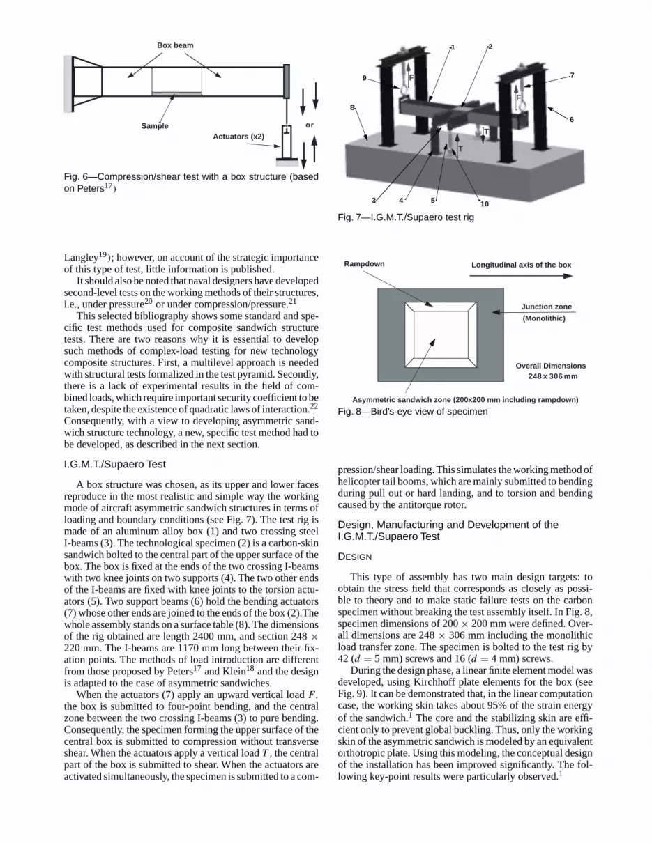
With the framework of the pyramid test method for thecertification of aeronautical structures, the second-level testsmust represent dimensioning cases of buckling under com-pression or shear. In the case of pure compression (Fig. 3),the sandwich panel is mounted on a support in a standard testmachine.
The variants mainly concern the management of theboundary conditions on the vertical surfaces (U-beams withgrease, knives, attached stiffeners, etc.) and the technologiesused for introducing the loads into the specimen.1,7–9 Somerecommendations can also be in the ASTM norm C364-94.The practical difficulties of this type of test, pointed out byHoff and Mautner in 1948, are the mastering of the bound-ary conditions, and the correct introduction of the compres-sion load on the middle plane of the specimen.10 A poorly-controlled introduction actually causes a nonlinear geometricbehavior1,11 even for symmetric sandwich structures.
© 2004 Society for Experimental Mechanics Experimental Mechanics • 461
Monolithic area
Rampdown region
Central area
Working skin
Stabilizing Skin
Neutral line
Compression
Shear
Membrane Loadings :
Fig. 1—Asymmetric sandwich structure technology
First Level
CouponsNon Specific
Hundreds of Specimens
Second Level
Dozens of Specimens
Elements
Details
Third Level
Fourth LevelSubcomponents
Dozens of Specimens
Some Parts
Full-Scale Testing
Non Specific
Specific
Specific
Fuselage,
Carbon Wing Box
Components
EntireAirc
raft
Test on the “Gazelle” helicopter Airbus A310 Wing Test
Sandwich
Inserts
in
Coupons
Sandwichplate
Fig. 2—Pyramid test method (based on Rouchon6)
Most tests of shear buckling are performed using a de-formable square, as shown in Fig. 4. The principle consistsof applying a load along the square vertical diagonal. Theframe will then transmit this load to the specimen, as well asa compression load along the horizontal. The stress field in thespecimen is then theoretically a pure state of shear. The loadsare transmitted from the frame to the specimen by bolting.This technology was first developed in the US Forest ProductLaboratory to test plywood12 and is also defined by ASTMnorm D2719. The method is widely used in the aeronauticalfields and also for testing naval structures.1,13,14 Neverthe-less, a uniform stress field in the sample can be obtained onlywith an adequate design. A poorly made frame will cause ex-cessive stresses in the corners and premature local failures.The real position of the articulated joint in the corners has anon-negligible influence in the stress field in the sample.13
Zagainov and Lozino-lozinsky8 recommend local cuts in thecorners of the sample and articulated joints centered on thecorners.
These two second-level structural tests produce reliableresults for determining the buckling stresses in compressionor shear. They have the advantage of being workable on stan-dard test machines, with relatively basic test rigs. However,especially for the pure compression test, the boundary condi-tions only imperfectly represent the junction technology andthe results are therefore very conservative.
Because aeronautical structures are submitted simultane-ously to compression and shear, the test pyramid logicallyimposes complementary tests under this type of combinedload. Apart from a few particular off-axis tests (obtained sim-ply by balancing the axis of the sample in the two classicaltests), these tests require the use of at least two actuators
462 • Vol. 44, No. 5, October 2004 © 2004 Society for Experimental Mechanics
Knives
U-guide
Stiffener
Fig. 3—Compression test rig
Loading
JointsSample
TheoreticalFrame stress field
Fig. 4—Deformable square
and the design of specific machines. Complex and expensiveto design and build, the few existing machines in the worldare mainly in aeronautical testing and research centers or ataircraft manufacturers whose results are rarely made public.Nevertheless, the technical solutions used can be divided intwo categories.
The first consists of directly reproducing the compres-sion/shear loads by means of actuators. Wolf and Kossira15
have presented a machine for testing fuselage skin panels (seeFig. 5, type 1). The upper and lower parts of the specimen arehoused with rigid fixtures. The lateral sides are fixed by 44silent-blocks to enable shear to be introduced while compres-sion is applied simultaneously. The specimen is loaded withshear by six actuators. Two horizontal actuators (A) producea load on the upper horizontal fixture. Four vertical actuators(B) work in pairs in opposite directions to transmit a load viaa lever to the two lateral beams. In this way, three of the spec-
Sample
Vertical Compression/Traction Actuators
Moving
Fixed Frame
TYPE 1
AA
BB
CC
TYPE 2
Shear Actuator
Horizontal Compression/Traction Actuators
Fixture
Fig. 5—Combined test rigs
imen’s four sides are solicited and the shear stress is carriedout correctly. Four more actuators (C) enable compression tobe introduced into the assembly. Finally, the beams makingup the frame are joined together with articulated joints. Wolfand Kossira15 do not mention the advantages and drawbacksof this method, but it is obviously technically complex andrequires operating 10 actuators.
Another machine that can carry out both biaxial ten-sile/compression and shear was developed for structures usedin the space industry.16 The specimen has a maximum cross-section of 700 × 1000 mm. The lower fixture is intentionallymounted free to avoid causing interference between loads.The actuators are controlled by position sensors, thus avoid-ing any rotation of the free fixture and the introduction ofparasite loads. Unlike the machine described previously, inwhich three of the four sides of the frame introduce the shearstress, this machine uses just one of the sides to introduce thesame type of load, and it can be observed that the loading iscloser to bending with shear than to pure shear.
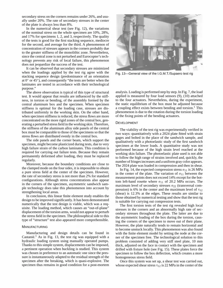
In Fig. 6, the second most frequent test method uses a boxstructure, of which one or more faces is replaced by the testspecimen. As early as 1947, Peters17 submitted a square-sectioned box to torsion and bending and was thus ableto identify an experimental curve of the compression/shearbuckling of the specimens which made the faces of the centralpart of the box. More recently, Klein18 used a box structurefixed to a support at one end and loaded under bending/torsionat the other end by means of two actuators. When the twoactuators are activated symmetrically, the box is loaded inbending. In this case, the lower box face, where the sampleis mounted, is submitted to tensile or compression stresses(and also to transverse shear). When the two actuators are ac-tivated antisymmetrically, the box is submitted to torsion andthe specimen which acts as a membrane take shear. Becausethe actuators are controlled, the two types of loading can becombined. The laminated or sandwich composite specimenis 1 m long and is bolted to the box by 180 bolts and a resininterface. It ensures the real boundary condition very closeto the “all-clamped” theoretical model, since the box itselfis very rigid. Klein claims to have obtained good results fordetermining critical buckling loads for sandwich plates 6–8 mm thick. He points out that it is impossible to determinethe stress flows entering the sample because of the numerousstructural redundancies. However, the flow is measured in situby equipping the specimen with 150 strain gages set out ina grid pattern. To our knowledge, other machines do existand are being used at large aircraft manufacturers or in aero-nautical test centers (CEAT, Toulouse, France, and NASA
© 2004 Society for Experimental Mechanics Experimental Mechanics • 463
Box beam
SampleActuators (x2)
or
Fig. 6—Compression/shear test with a box structure (basedon Peters17)
Langley19); however, on account of the strategic importanceof this type of test, little information is published.
It should also be noted that naval designers have developedsecond-level tests on the working methods of their structures,i.e., under pressure20 or under compression/pressure.21
This selected bibliography shows some standard and spe-cific test methods used for composite sandwich structuretests. There are two reasons why it is essential to developsuch methods of complex-load testing for new technologycomposite structures. First, a multilevel approach is neededwith structural tests formalized in the test pyramid. Secondly,there is a lack of experimental results in the field of com-bined loads, which require important security coefficient to betaken, despite the existence of quadratic laws of interaction.22
Consequently, with a view to developing asymmetric sand-wich structure technology, a new, specific test method had tobe developed, as described in the next section.
I.G.M.T./Supaero Test
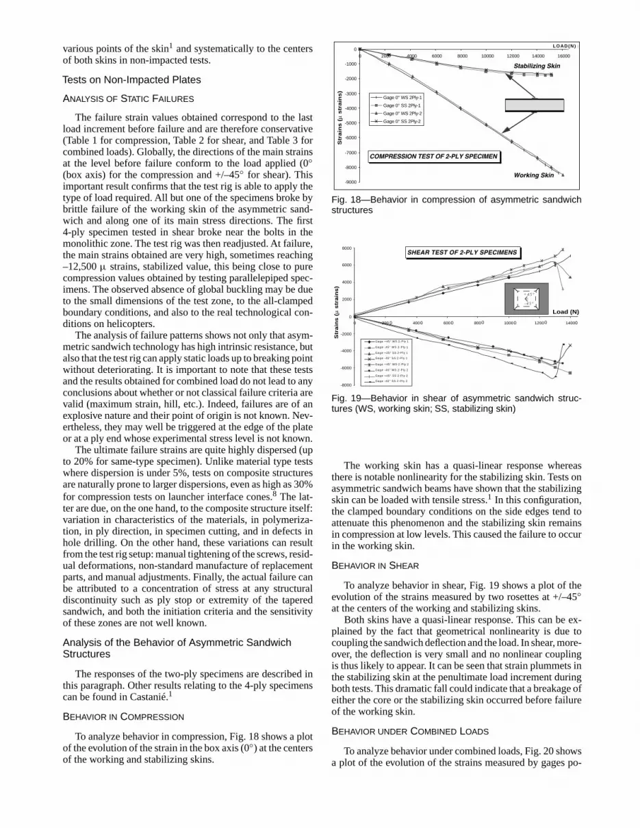
A box structure was chosen, as its upper and lower facesreproduce in the most realistic and simple way the workingmode of aircraft asymmetric sandwich structures in terms ofloading and boundary conditions (see Fig. 7). The test rig ismade of an aluminum alloy box (1) and two crossing steelI-beams (3). The technological specimen (2) is a carbon-skinsandwich bolted to the central part of the upper surface of thebox. The box is fixed at the ends of the two crossing I-beamswith two knee joints on two supports (4). The two other endsof the I-beams are fixed with knee joints to the torsion actu-ators (5). Two support beams (6) hold the bending actuators(7) whose other ends are joined to the ends of the box (2).Thewhole assembly stands on a surface table (8). The dimensionsof the rig obtained are length 2400 mm, and section 248 ×220 mm. The I-beams are 1170 mm long between their fix-ation points. The methods of load introduction are differentfrom those proposed by Peters17 and Klein18 and the designis adapted to the case of asymmetric sandwiches.
When the actuators (7) apply an upward vertical load F,the box is submitted to four-point bending, and the centralzone between the two crossing I-beams (3) to pure bending.Consequently, the specimen forming the upper surface of thecentral box is submitted to compression without transverseshear. When the actuators apply a vertical load T , the centralpart of the box is submitted to shear. When the actuators areactivated simultaneously, the specimen is submitted to a com-
1 2
3 4 5
6
8
79
10
F
F
T
T
Fig. 7—I.G.M.T./Supaero test rig
Junction zone
Asymmetric sandwich zone (200x200 mm including rampdown)
Longitudinal axis of the box
(Monolithic)
Overall Dimensions248 x 306 mm
Rampdown
Fig. 8—Bird’s-eye view of specimen
pression/shear loading. This simulates the working method ofhelicopter tail booms, which are mainly submitted to bendingduring pull out or hard landing, and to torsion and bendingcaused by the antitorque rotor.
Design, Manufacturing and Development of theI.G.M.T./Supaero Test
DESIGN
This type of assembly has two main design targets: toobtain the stress field that corresponds as closely as possi-ble to theory and to make static failure tests on the carbonspecimen without breaking the test assembly itself. In Fig. 8,specimen dimensions of 200 × 200 mm were defined. Over-all dimensions are 248 × 306 mm including the monolithicload transfer zone. The specimen is bolted to the test rig by42 (d = 5 mm) screws and 16 (d = 4 mm) screws.
During the design phase, a linear finite element model wasdeveloped, using Kirchhoff plate elements for the box (seeFig. 9). It can be demonstrated that, in the linear computationcase, the working skin takes about 95% of the strain energyof the sandwich.1 The core and the stabilizing skin are effi-cient only to prevent global buckling. Thus, only the workingskin of the asymmetric sandwich is modeled by an equivalentorthotropic plate. Using this modeling, the conceptual designof the installation has been improved significantly. The fol-lowing key-point results were particularly observed.1
464 • Vol. 44, No. 5, October 2004 © 2004 Society for Experimental Mechanics

Deformed scale: 28
Fig. 9—Deflection field of the box under combined loading1
COMPRESSION STRESS FLOW LOCAL BENDING MOMENT
Upper skin of the box
Web of the I-beam
Working skin of Upper I-beam boomthe specimen
Fig. 10—Compression flow route
• In the first design loop, the torsion was introduced bytriangular arms. The finite element model showed thatthe stress concentration in the test sample and in thebox can be diminished by using I-beams.
• The load introduction boxes must be made global andlocal buckling proof by using stiffener and using steelfor the upper skin.
• In Fig. 10, the compressive loading is transferred fromthe upper skin of the box to the specimen via the up-per boom of the I-beams. The different shifts of theneutral line generate local bending moment. After test-ing several designs, the boom of the I-beam must berigid enough (8 mm) to minimize these local bendingeffects. It is not a drawback if local stiffness is muchhigher than that of the specimen since the junction issituated in the monolithic zone of the specimen, whichis itself extremely stiff.
Once the design has been finalized, the finite elementmodel should enable an a priori study of the stress fieldsobtained in the working skin of the specimen. Numericalcompression and shear tests were carried out for three dif-ferent stacking sequences of the working skin issued fromEurocopter’s own technology. Figures 11 and 12 show thenumerical secondary stress rates (i.e., plane stresses whichare not the nominal stress) compared to expected nominalstress (σ11 in compression and τ12 in shear).
In the numerical compression test (see Fig. 11), the varia-tion of stress σ11on the plate is not over 10%. The local rate of
LAMINATE N° 2 :
σ22 : 1.9%τ12 : 0.03 %
σ22 : 12%τ12 : 0.4%
σ22 : 0.5%τ12 : 5.3%
σ22 : 7.5%τ12 : 7.2%
σ22 : 0.09 %τ12 : 0.1 %
LAMINATE N° 1 :
σ22 : 6.4%τ12 : 0.1 %
σ22 : 26%τ12 : 1%
σ22 : 5%τ12 : 14.8%
σ22 : 17.5%τ12 : 18%
σ22 : 0.03 %τ12 : 0.05 %
LAMINATE N° 3 :
σ22 : 8 %τ12 : 0.13 %
σ22 : 28 %τ12 : 1.2 %
σ22 : 5.4 %τ12 : 16 %
σ22 : 18 %
τ12 : 19.5 %
σ22 : 0.13 %τ12 : 0.17 %
BOX AXIS2
1
IPN side
Center :
Side panel edge
IPN side
Center :
Side panel edge
IPN side
Center :
Side panel edge
Fig. 11—Secondary stresses obtained in the compressionnumerical test
LAMINATE N° 2:
σ11 : 0.9%σ22 : 0.016 %
σ11 : 33%σ22 : 1.8%
σ11 : 0.1%σ22 : 1.5%
σ11 : 16%
σ11 : 0.17 %σ22 : 0.17 %
LAMINATE N° 1 :
σ11 : 0.2%σ22 : 0.13 %
σ11 : 1,2%σ22 : 0.2%
σ11 : 45%σ22 : 16%
σ11 : 24%
σ11 : 0.9 %σ22 : 1.1%
LAMINATE N° 3:
σ11 : 0.2%σ22 : 0.1%
σ11 : 101%σ22 : 0.87% σ11 : 3.8%
σ22 : 1.2%
σ11 : 1.6%σ22 : 0.1%
BOX AXIS
σ11 : 59%
σ11 : 48%
σ11 : 23%
(variation of ττ12: 10% )
2
1
(variation of ττ12: 17% )
(variation of ττ12: 28% )
IPN side
Center :
Side panel edge
IPN side
Center :
Side panel edge
IPN side
Center :
Side panel edge
Fig. 12—Secondary stresses obtained in the shear numericaltest
© 2004 Society for Experimental Mechanics Experimental Mechanics • 465
secondary stress on the corners remains under 26%, and usu-ally under 20%. The rate of secondary stresses in the centerof the plate is always less than 8%.
In the numerical shear test (see Fig. 12), the variationsof the nominal stress on the whole specimen are 10%, 28%,and 17% for specimens 1, 2, and 3, respectively. The qualityof the tests is good for the first stacking sequence, mediocrefor the second, and average for the third. A phenomenon ofconcentration of stresses appears in the corners probably dueto the greater stiffness of the monolithic zone. Nevertheless,since the central zone is not perturbed and Eurocopter’s tech-nology prevents any risk of local failure, this phenomenondoes not jeopardize the success of the test.
It can be observed that secondary stresses are minimizedwhen the loadings applied by the test rig agree with thestacking sequence design (predominance of an orientationat 0◦ or 45◦), and consequently “the tests are better when thelaminates are tested in accordance with their technologicalpurpose.”
The above observation is typical of this type of structuraltest. It would appear that results are influenced by the stiff-ness, in torsion or bending, of the assembly formed by thecentral aluminum box and the specimen. When specimenstiffness is optimal for the loading case, stresses are dis-tributed uniformly in the working skin. On the other hand,when specimen stiffness is reduced, the stress flows are moreconcentrated on the more rigid zones of the central box, gen-erating a perturbed stress field in the working skin. Therefore,the stiffness of the aluminum alloy side panels of the centralbox must be comparable to those of the specimens so that thestress flows are distributed evenly in the central box.
The side panels and the corner beam, which support thespecimen, might become plasticized during tests, due to veryhigh failure strain of the carbon laminates. This condition isrequired for carrying out failure tests. Because they remainpermanently deformed after loading, they must be replacedregularly.
Moreover, because the boundary conditions are close tothe clamped mode on the four sides, it is impossible to obtaina pure stress field at the center of the specimen. However,the rate of secondary stress is not more than 2% for standardconfigurations. Although stress concentrations also appearin the corners of the specimen, asymmetric sandwich sam-ple technology does take this phenomenon into account bystrengthening local areas.
In conclusion, this linear finite element study enables thedesign to be improved significantly. It has been demonstratednumerically that the test design is viable, which was a req-uisite. The loading method, which causes an “out-of-plane”displacement of the torsion arms, would not appear to perturbthe stress field in the specimen. The philosophical side to thistype of “structure” test also appeared more comprehensible.
MANUFACTURING
Manufacturing and design details can be found inCastanié.1 As in Fig. 13, the test rig was equipped with ahydraulic loading system using manually operated pumps.Thanks to this simple system, displacements can be imposed,a pertinent operation when buckling is studied. This systemwas chosen in preference to an automatic one since the pres-sure is instantaneously adapted to the residual strength of thespecimen after the breaking, which is quasi-explosive. Thespecimen thus remains in good condition for a post-mortem
Fig. 13—General view of the I.G.M.T./Supaero test rig
analysis. Loading is performed step by step. In Fig. 7, the loadapplied is measured by four load sensors (9), (10) attachedto the four actuators. Nevertheless, during the experiment,the static equilibrium of the box must be adjusted becausea coupling effect exists between bending and torsion.1 Thisphenomenon is due to the rotation during the torsion loadingof the fixing points of the bending actuators.
DEVELOPMENT
The viability of the test rig was experimentally verified intwo ways: quantitatively with a 2024 plate fitted with straingages and bolted in the place of the sandwich sample, andqualitatively with a photoelastic study of the first sandwichspecimen at the lower loads. A quantitative study was notperformed because of the high strain level reached at theworking skin failure. The photoelastic plate used is not ableto follow the high range of strains involved and, quickly, thenumber of fringes increases and a uniform gray color appears.The 2024 plate was loaded in compression and then in shear.
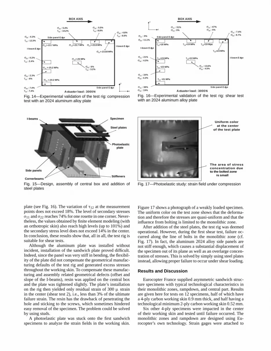
In Fig. 14, the expected compression stress σ11 is 26 MPain the center of the plate. The variation of σ11 between themeasurement points does not exceed 14% except for the bot-tom left-hand rosette where σ11 of 20.2 MPa occurs. Themaximum level of secondary stresses σ22 (transversal com-pression) is 6% in the center and the maximum level of τ12(shear) is 12.3% at the edges. These results are similar tothose obtained by numerical testing and show that the test rigis suitable for carrying out compression tests.
The first torsion tests of the test rig revealed high localstresses in the corners and an abnormally high rate of sec-ondary stresses throughout the plate. The latter are due tothe asymmetric loading of the box during the torsion, caus-ing the corners of the specimen to move out of their plane.However, the plate naturally tends to remain horizontal andto become unstuck locally. This phenomenon was also foundwith the finite element model by setting the node at the cor-ner of the specimen free. The technological solution to thisproblem consisted of adding very stiff steel plate, 10 mmthick, adjusted on the face in contact with the specimen anddrilled with fixture hole (see Fig. 15). These plates force thespecimen to follow the box deflection, which creates a morehomogeneous stress field.
Once this system was set up, a shear test was carried out,whose expected shear stress τ12 is 22 MPa in the center of the
466 • Vol. 44, No. 5, October 2004 © 2004 Society for Experimental Mechanics
σ11=-22.8 MPa
σ22 : 4.8%
σ11 =-20.2 MPa
σ22 : 6.3%
σ11=-22.7 MPa
σ22 : 0.2%
σ11=-22.7 MPa
σ22 : 5.4%
σ11=-26 MPa
BOX AXIS
σ11=-23.58 MPa
σ11 =-25.2 MPa
σ22 : 2.3%
σ22 : 5.5%
σ22 : 7.4%
τ12 : 12.3%
τ12 : 2.4%
τ12 : 6%
τ12 : 7.4%
τ12 : 10.2% τ12 : 8.8%
τ12 : 6.6%
σ22 : 6%τ12 : 3.2%
2
1Actuator load : 3000 N
I-beam E dgeI-beam E dge
S ide panel E dge
S ide panel E dge
Fig. 14—Experimental validation of the test rig: compressiontest with an 2024 aluminum alloy plate
I-beams
Side panels
StiffenersCornerbeams
Specimen
Steel plates
Photoelasticplate
Fig. 15—Design, assembly of central box and addition ofsteel plates
plate (see Fig. 16). The variation of τ12 at the measurementpoints does not exceed 18%. The level of secondary stressesσ11 and σ22 reaches 74% for one rosette in one corner. Never-theless, the values obtained by finite element modeling (withan orthotropic skin) also reach high levels (up to 101%) andthe secondary stress level does not exceed 14% in the center.In conclusion, these results show that, all in all, the test rig issuitable for shear tests.
Although the aluminum plate was installed withoutincident, installation of the sandwich plate proved difficult.Indeed, since the panel was very stiff in bending, the flexibil-ity of the plate did not compensate the geometrical manufac-turing defaults of the test rig and generated excess stressesthroughout the working skin. To compensate these manufac-turing and assembly related geometrical defects (offset andslope of the I-beams), resin was applied on the central boxand the plate was tightened slightly. The plate’s installationon the rig then yielded only residual strain of 300 µ strainin the center (shear test 2), i.e., less than 3% of the ultimatefailure strain. The resin has the drawback of penetrating thehole and sticking to the screws, which sometimes hinderedeasy removal of the specimen. The problem could be solvedby using studs.
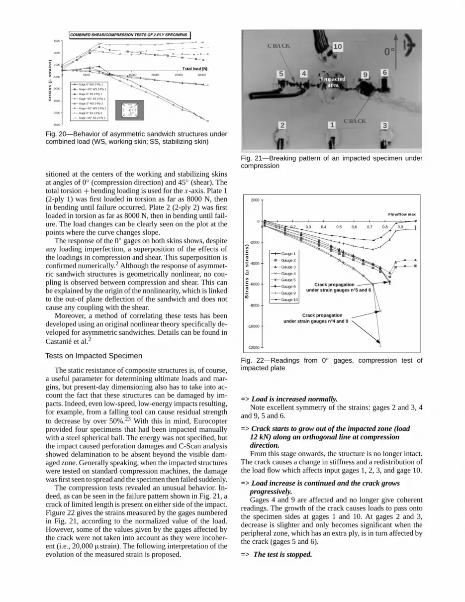
A photoelastic plate was stuck onto the first sandwichspecimens to analyze the strain fields in the working skin.
τ12=19 Mpa
σ11 : 7.4%
τ12 =21 MPa
σ11 : 0%
τ12=19 MPa
σ11 : 21%
τ12=18 MPa
σ11 : 31%
τ12=22 MPaτ12=23 MPa
BOX AXIS
τ12=23 MPa
τ12 =23 MPa
σ11 : 34%
σ11 : 47%
σ11 : 38%
σ22 : 11.1%
σ22 : 4.3%
σ22 : 4.3%
σ22 : 19%
σ22 : 0% σ22 : 5%
σ22 : 8.7%
σ11 : 13.6%σ22 : 4.5%
2
1
Actuator load : 3000 N
S ide panel E dge
S ide panel E dge
I-beam E dge
I-beam E dge
Fig. 16—Experimental validation of the test rig: shear testwith an 2024 aluminum alloy plate
Uniform colorat the center
of the test plate
The area of stress concentration dueto the bolted zone
is small
Fig. 17—Photoelastic study: strain field under compression
Figure 17 shows a photograph of a weakly loaded specimen.The uniform color on the test zone shows that the deforma-tion and therefore the stresses are quasi-uniform and that theinfluence from bolting is limited to the monolithic zone.
After addition of the steel plates, the test rig was deemedoperational. However, during the first shear test, failure oc-curred along the line of bolts in the monolithic zone (cf.Fig. 17). In fact, the aluminum 2024 alloy side panels arenot stiff enough, which causes a substantial displacement ofthe specimen out of its plane as well as an overlarge concen-tration of stresses. This is solved by simply using steel platesinstead, allowing proper failure to occur under shear loading.
Results and Discussion
Eurocopter France supplied asymmetric sandwich struc-ture specimens with typical technological characteristics intheir monolithic zones, rampdown, and central part. Resultsare given here for tests on 12 specimens, half of which havea 4-ply carbon working skin 0.9 mm thick, and half having atechnological minimum 2-ply carbon working skin 0.52 mm.
Six other 4-ply specimens were impacted in the centerof their working skin and tested until failure occurred. Themonolithic zones and rampdown are designed using Eu-rocopter’s own technology. Strain gages were attached to
© 2004 Society for Experimental Mechanics Experimental Mechanics • 467
various points of the skin1 and systematically to the centersof both skins in non-impacted tests.
Tests on Non-Impacted Plates
ANALYSIS OF STATIC FAILURES
The failure strain values obtained correspond to the lastload increment before failure and are therefore conservative(Table 1 for compression, Table 2 for shear, and Table 3 forcombined loads). Globally, the directions of the main strainsat the level before failure conform to the load applied (0◦(box axis) for the compression and +/–45◦ for shear). Thisimportant result confirms that the test rig is able to apply thetype of load required. All but one of the specimens broke bybrittle failure of the working skin of the asymmetric sand-wich and along one of its main stress directions. The first4-ply specimen tested in shear broke near the bolts in themonolithic zone. The test rig was then readjusted. At failure,the main strains obtained are very high, sometimes reaching–12,500 µ strains, stabilized value, this being close to purecompression values obtained by testing parallelepiped spec-imens. The observed absence of global buckling may be dueto the small dimensions of the test zone, to the all-clampedboundary conditions, and also to the real technological con-ditions on helicopters.
The analysis of failure patterns shows not only that asym-metric sandwich technology has high intrinsic resistance, butalso that the test rig can apply static loads up to breaking pointwithout deteriorating. It is important to note that these testsand the results obtained for combined load do not lead to anyconclusions about whether or not classical failure criteria arevalid (maximum strain, hill, etc.). Indeed, failures are of anexplosive nature and their point of origin is not known. Nev-ertheless, they may well be triggered at the edge of the plateor at a ply end whose experimental stress level is not known.
The ultimate failure strains are quite highly dispersed (upto 20% for same-type specimen). Unlike material type testswhere dispersion is under 5%, tests on composite structuresare naturally prone to larger dispersions, even as high as 30%for compression tests on launcher interface cones.8 The lat-ter are due, on the one hand, to the composite structure itself:variation in characteristics of the materials, in polymeriza-tion, in ply direction, in specimen cutting, and in defects inhole drilling. On the other hand, these variations can resultfrom the test rig setup: manual tightening of the screws, resid-ual deformations, non-standard manufacture of replacementparts, and manual adjustments. Finally, the actual failure canbe attributed to a concentration of stress at any structuraldiscontinuity such as ply stop or extremity of the taperedsandwich, and both the initiation criteria and the sensitivityof these zones are not well known.
Analysis of the Behavior of Asymmetric SandwichStructures
The responses of the two-ply specimens are described inthis paragraph. Other results relating to the 4-ply specimenscan be found in Castanié.1
BEHAVIOR IN COMPRESSION
To analyze behavior in compression, Fig. 18 shows a plotof the evolution of the strain in the box axis (0◦) at the centersof the working and stabilizing skins.
COMPRESSION TEST OF 2-PLY SPECIMEN
-9000
-8000
-7000
-6000
-5000
-4000
-3000
-2000
-1000
0
0 200 4000 6000 8000 10000 12000 14000 16000
(daN)
Str
ains
(µs
trai
n)
Gage 0° WS 2Ply-1
Gage 0° SS 2Ply-1
Gage 0° WS 2Ply-2
Gage 0° SS 2Ply-2
Stabilizing Skin
Working Skin
0
Str
ain
s (
µ s
train
s)
LOAD(N)
Fig. 18—Behavior in compression of asymmetric sandwichstructures
SHEAR TEST OF 2-PLY SPECIMENS
-8000
-6000
-4000
-2000
0
2000
4000
6000
8000
0 200 400 600 800 1000 1200 1400
Gage +45° WS 2-Ply 1
Gage -45° WS 2-Ply 1
Gage +45° SS 2-Ply 1
Gage -45° SS 2-Ply 1
Gage +45° WS 2-Ply 2
Gage -45° WS 2-Ply 2
Gage +45° SS 2-Ply 2
Gage -45° SS 2-Ply 2
+ 4 5 °
- 4 5 °
Load (N)
Str
ain
s (
µ s
train
s)
000 0 0 0 0
Fig. 19—Behavior in shear of asymmetric sandwich struc-tures (WS, working skin; SS, stabilizing skin)
The working skin has a quasi-linear response whereasthere is notable nonlinearity for the stabilizing skin. Tests onasymmetric sandwich beams have shown that the stabilizingskin can be loaded with tensile stress.1 In this configuration,the clamped boundary conditions on the side edges tend toattenuate this phenomenon and the stabilizing skin remainsin compression at low levels. This caused the failure to occurin the working skin.
BEHAVIOR IN SHEAR
To analyze behavior in shear, Fig. 19 shows a plot of theevolution of the strains measured by two rosettes at +/–45◦at the centers of the working and stabilizing skins.
Both skins have a quasi-linear response. This can be ex-plained by the fact that geometrical nonlinearity is due tocoupling the sandwich deflection and the load. In shear, more-over, the deflection is very small and no nonlinear couplingis thus likely to appear. It can be seen that strain plummets inthe stabilizing skin at the penultimate load increment duringboth tests. This dramatic fall could indicate that a breakage ofeither the core or the stabilizing skin occurred before failureof the working skin.
BEHAVIOR UNDER COMBINED LOADS
To analyze behavior under combined loads, Fig. 20 showsa plot of the evolution of the strains measured by gages po-
468 • Vol. 44, No. 5, October 2004 © 2004 Society for Experimental Mechanics

TABLE 1—MAIN COMPRESSIVE STRAINS AT THE CENTER OF THE WORKING SKIN JUST BEFOREFAILURE (UNITS ARE µ STRAINS) AND WORKING SKIN BREAKING LINES
SPECIMEN 4 P L Y - 1 4 P L Y - 2 2 P L Y - 1 2 P L Y - 2
DIRECTION 2° 1.58° 0.5° (step n-1) 1° (step n-1)
εε1 (µstrains) -10467 -12510 -8510 -8400
εε2 (µstrains) 1391 1191 #### (not measured) ####(not measured)
FAILUREBREAKINGPATTERN
TABLE 2—MAIN SHEAR STRAINS AT THE CENTER OF THE WORKING SKIN JUST BEFOREFAILURE (UNITS ARE µ STRAINS) AND WORKING SKIN BREAKING LINES
SPECIMEN 4 P L Y - 1 4 P L Y - 2 2 P L Y - 1 2 P L Y - 2
DIRECTION -45,36° -50,28° -44,35° -38,76°
εε1 (µstrains) -12453 -10484 -6592 -5617
εε2 (µstrains) 10291 9154 7082 7961
FAILUREBREAKINGPATTERN
TABLE 3—MAIN COMBINED COMPRESSION/SHEAR STRAINS AT THE CENTER OF THE WORKINGSKIN BEFORE FAILURE (UNITS ARE µ STRAINS), COMPRESSIVE VALUES IN THE 0◦ AND 45◦ PLYDIRECTIONS AND WORKING SKIN BREAKING LINES
SPECIMEN 4 P L Y - 1 4 P L Y - 2 2 P L Y - 1 2 P L Y - 2
DIRECTION -28° P LY -29° P LY -25° P LY -16,7° P LY
εε1 (µstrains) -100170° P ly :-6400
-114100° P ly :-7300
-103000° P ly :-7956
-96800° P ly :
-8350
εε2 (µstrains) 352245° P ly: -8859
536045° P ly :-10135
350045° P ly:
-85886400
45° P ly:-6059
FAILUREBREAKINGPATTERN
COMBINED SHEAR/COMPRESSION TESTS OF 2-PLY SPECIMENS
-9000
-7000
-5000
-3000
-1000
1000
3000
5000
0 500 1000 1500 2000 2500 3000
T OT AL L OA D (daN)
Str
ain
s (µ
Str
ain
s)
Gage 0° WS 2-Ply 1
Gage +45° WS 2-Ply 1
Gage 0° SS 2-Ply 1
Gage +45° SS 2-Ply 1
Gage 0° WS 2-Ply 2
Gage +45° WS 2-Ply 2
Gage 0° SS 2-Ply 2
Gage +45° SS 2-Ply 2
+ 4 5 °
- 4 5 °0°
0 0 0 0 0 0
Str
ain
s (
µ s
tra
ins
)
Total load (N)
Fig. 20—Behavior of asymmetric sandwich structures undercombined load (WS, working skin; SS, stabilizing skin)
sitioned at the centers of the working and stabilizing skinsat angles of 0◦ (compression direction) and 45◦ (shear). Thetotal torsion + bending loading is used for the x-axis. Plate 1(2-ply 1) was first loaded in torsion as far as 8000 N, thenin bending until failure occurred. Plate 2 (2-ply 2) was firstloaded in torsion as far as 8000 N, then in bending until fail-ure. The load changes can be clearly seen on the plot at thepoints where the curve changes slope.
The response of the 0◦ gages on both skins shows, despiteany loading imperfection, a superposition of the effects ofthe loadings in compression and shear. This superposition isconfirmed numerically.2 Although the response of asymmet-ric sandwich structures is geometrically nonlinear, no cou-pling is observed between compression and shear. This canbe explained by the origin of the nonlinearity, which is linkedto the out-of plane deflection of the sandwich and does notcause any coupling with the shear.
Moreover, a method of correlating these tests has beendeveloped using an original nonlinear theory specifically de-veloped for asymmetric sandwiches. Details can be found inCastanié et al.2
Tests on Impacted Specimen
The static resistance of composite structures is, of course,a useful parameter for determining ultimate loads and mar-gins, but present-day dimensioning also has to take into ac-count the fact that these structures can be damaged by im-pacts. Indeed, even low-speed, low-energy impacts resulting,for example, from a falling tool can cause residual strengthto decrease by over 50%.23 With this in mind, Eurocopterprovided four specimens that had been impacted manuallywith a steel spherical ball. The energy was not specified, butthe impact caused perforation damages and C-Scan analysisshowed delamination to be absent beyond the visible dam-aged zone. Generally speaking, when the impacted structureswere tested on standard compression machines, the damagewas first seen to spread and the specimen then failed suddenly.
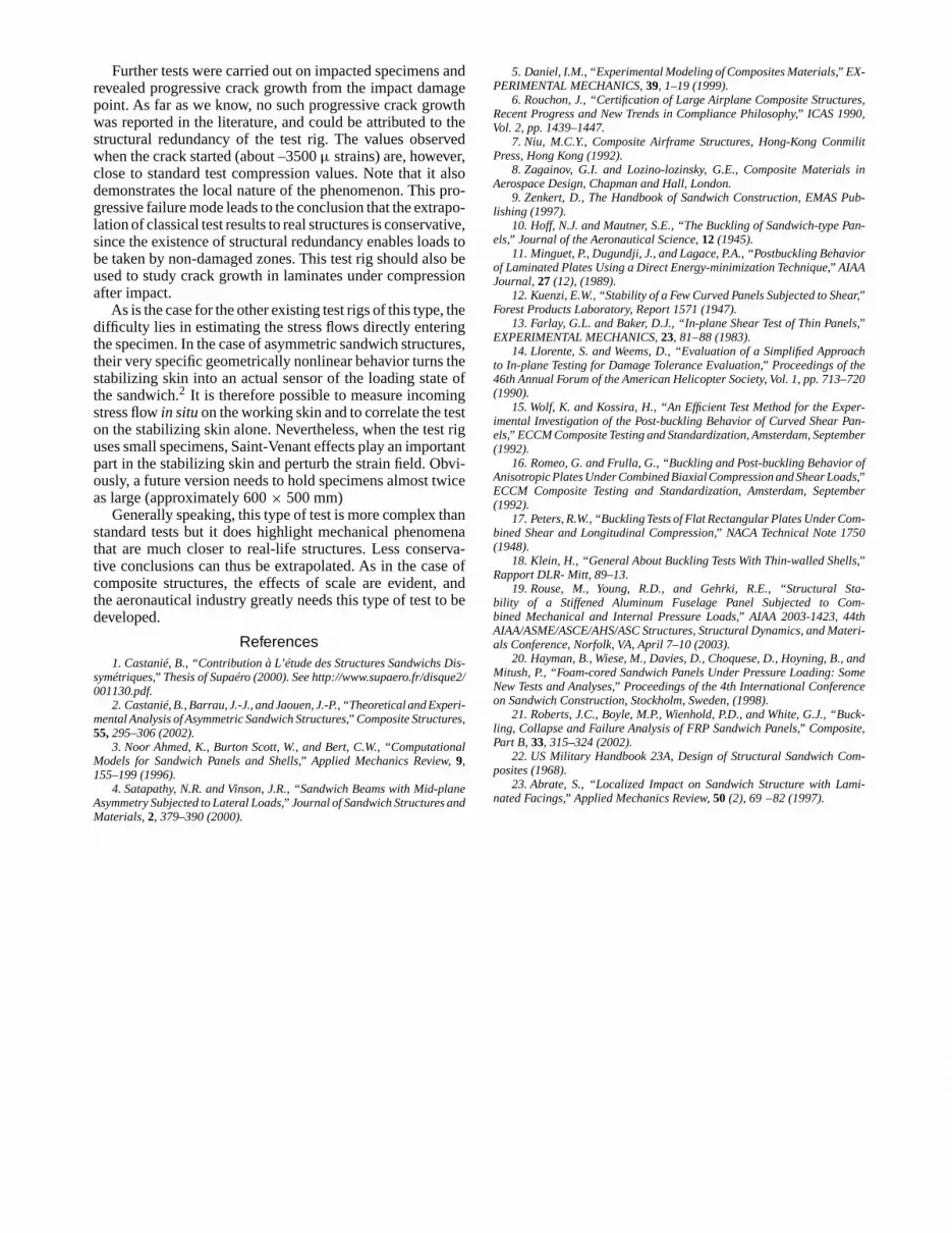
The compression tests revealed an unusual behavior. In-deed, as can be seen in the failure pattern shown in Fig. 21, acrack of limited length is present on either side of the impact.Figure 22 gives the strains measured by the gages numberedin Fig. 21, according to the normalized value of the load.However, some of the values given by the gages affected bythe crack were not taken into account as they were incoher-ent (i.e., 20,000 µstrain). The following interpretation of theevolution of the measured strain is proposed.
C RA CK
C RA CK
areaI mpacted
12 3
45 69
10 0°
Fig. 21—Breaking pattern of an impacted specimen undercompression
-12000
-10000
-8000
-6000
-4000
-2000
0
2000
0 0,1 0,2 0,3 0,4 0,5 0,6 0,7 0,8 0,9 1
F low/flow max
Mic
ro-s
trai
nsGauge 1
Gauge 2
Gauge 3
Gauge 4
Gauge 5
Gauge 6
Gauge 9
Gauge 10
Crack propagation under strain gauges n°5 and 6
Str
ain
s (
µ s
tra
ins
)
Crack propagation under strain gauges n°4 and 9
Fig. 22—Readings from 0◦ gages, compression test ofimpacted plate
=> Load is increased normally.Note excellent symmetry of the strains: gages 2 and 3, 4
and 9, 5 and 6.
=> Crack starts to grow out of the impacted zone (load12 kN) along an orthogonal line at compressiondirection.From this stage onwards, the structure is no longer intact.
The crack causes a change in stiffness and a redistribution ofthe load flow which affects input gages 1, 2, 3, and gage 10.
=> Load increase is continued and the crack growsprogressively.Gages 4 and 9 are affected and no longer give coherent
readings. The growth of the crack causes loads to pass ontothe specimen sides at gages 1 and 10. At gages 2 and 3,decrease is slighter and only becomes significant when theperipheral zone, which has an extra ply, is in turn affected bythe crack (gages 5 and 6).
=> The test is stopped.
470 • Vol. 44, No. 5, October 2004 © 2004 Society for Experimental Mechanics

No loading 4650 N
9450 N 12100 N F I S S U R A T I O N
8600 N
0° : compression direction
C rack
Fig. 23—Stages of the damaged area in compression afterimpact by the moiré shadow method
It is remarkable to observe such “growth” of a crack, asan explosive failure usually occurs as soon as a crack ap-pears. The phenomenon observed may be due to working inimposed displacement as well as the various reinforcementspresent in asymmetric sandwich structures, e.g., the struc-tural redundancy of the test rig. Before the crack appears,strain of –3873 and –2613 µ strains were obtained by cal-culating the average of the values given by gages 1, 2, and3, representing a drop in resistance of about 75%. As shownin Fig. 23, a qualitative analysis of the deformed shape (dueto the bad quality of the grid used) using the shadow moirémethod was carried out during the second test. The evolutionof the pattern of the impact provides information on the fail-ure scenario under compression after impact, which seems tobe the appearance of a progressively deeper elliptical dam-aged zone caused by extension of the local crushing of thehoneycomb core, followed by the start of the crack at the apexof the ellipse, probably initiated by local static overstresses.
The two remaining specimens were tested in shear and un-der combined loads. Photographs of the failures are shown inFigs. 24 and 25. In the shear test, failure was sudden, along a45◦ line approximately and strains at the hole edges reachedabout 12,000 µ strains. In impacted shear, the response ofthe structure thus appears analog to a failure by concentra-tion of stresses around a hole. In fact, the strain values ob-tained would appear to confirm the absence of delaminationcaused by the impact. Under combined loads, a phenomenonoccurred which was analog to that observed in compression.1
First, the specimen was compression loaded. Rosettes situ-ated in the same places as gages 1–2–3, shown in Fig. 21,supplied an average strain of –3644 µ strain at 0◦. At thisstage, the structure is intact with no cracks outside the im-pacted area. It was then shear-loaded and a crack very soonappeared. Just before final failure, these rosettes indicated amain direction near to 45◦. This shows that the crack com-pletely unloaded the zone in compression and that the stressflow was redirected to the peripheral zones of the specimenand to the test rig itself. The gages positioned close to theimpact came unstuck during growth of the crack, makingquantitative interpretation of the test difficult.
The test rig has thus proved suitable for impacted specimentests and enabled an original progressive crack phenomenon
Fig. 24—Failure pattern in shear of an impacted specimen
Fig. 25—Failure pattern under combined load of an impactedspecimen
to be closely observed. Little is known about how stratifiedstructures crack and this method of experimenting, which canenable propagation in “small leaps”, could be used to validatean initiation test. Moreover, from a practical point of view,the non-explosive crack growth attributable to the structuralredundancy of the box gives aeronautical structure designerssafety margins not shown by standard tests.
Conclusions
A test rig was developed to test asymmetric sandwich spec-imens under combined compression/shear loads. It conformsto the second level of the test pyramid. A box structure waschosen and tests simulated as realistically as possible the con-ditions in aeronautical structures, particularly junctions andboundary conditions. The test rig proved capable of carry-ing out static failure tests on specimens with carbon laminateskins. The tests effectuated showed asymmetric structuresto be exceptionally strong in compression, since no globalbuckling was observed and failure strains are similar to thosemeasured on single-material specimens, being more than–10,000 µ strains at failure. The shear and combined loadtests produce results which are analog for breaking patternsand failure strains.
© 2004 Society for Experimental Mechanics Experimental Mechanics • 471
Further tests were carried out on impacted specimens andrevealed progressive crack growth from the impact damagepoint. As far as we know, no such progressive crack growthwas reported in the literature, and could be attributed to thestructural redundancy of the test rig. The values observedwhen the crack started (about –3500 µ strains) are, however,close to standard test compression values. Note that it alsodemonstrates the local nature of the phenomenon. This pro-gressive failure mode leads to the conclusion that the extrapo-lation of classical test results to real structures is conservative,since the existence of structural redundancy enables loads tobe taken by non-damaged zones. This test rig should also beused to study crack growth in laminates under compressionafter impact.
As is the case for the other existing test rigs of this type, thedifficulty lies in estimating the stress flows directly enteringthe specimen. In the case of asymmetric sandwich structures,their very specific geometrically nonlinear behavior turns thestabilizing skin into an actual sensor of the loading state ofthe sandwich.2 It is therefore possible to measure incomingstress flow in situon the working skin and to correlate the teston the stabilizing skin alone. Nevertheless, when the test riguses small specimens, Saint-Venant effects play an importantpart in the stabilizing skin and perturb the strain field. Obvi-ously, a future version needs to hold specimens almost twiceas large (approximately 600 × 500 mm)
Generally speaking, this type of test is more complex thanstandard tests but it does highlight mechanical phenomenathat are much closer to real-life structures. Less conserva-tive conclusions can thus be extrapolated. As in the case ofcomposite structures, the effects of scale are evident, andthe aeronautical industry greatly needs this type of test to bedeveloped.
References1. Castanié, B., “Contribution à L’étude des Structures Sandwichs Dis-
symétriques,” Thesis of Supaéro (2000). See http://www.supaero.fr/disque2/001130.pdf.
2. Castanié, B., Barrau, J.-J., and Jaouen, J.-P., “Theoretical and Experi-mental Analysis of Asymmetric Sandwich Structures,” Composite Structures,55, 295–306 (2002).
3. Noor Ahmed, K., Burton Scott, W., and Bert, C.W., “ComputationalModels for Sandwich Panels and Shells,” Applied Mechanics Review,9,155–199 (1996).
4. Satapathy, N.R. and Vinson, J.R., “Sandwich Beams with Mid-planeAsymmetry Subjected to Lateral Loads,” Journal of Sandwich Structures andMaterials,2, 379–390 (2000).
5. Daniel, I.M., “Experimental Modeling of Composites Materials,” EX-PERIMENTAL MECHANICS,39, 1–19 (1999).
6. Rouchon, J., “Certification of Large Airplane Composite Structures,Recent Progress and New Trends in Compliance Philosophy,” ICAS 1990,Vol. 2, pp. 1439–1447.
7. Niu, M.C.Y., Composite Airframe Structures, Hong-Kong ConmilitPress, Hong Kong (1992).
8. Zagainov, G.I. and Lozino-lozinsky, G.E., Composite Materials inAerospace Design, Chapman and Hall, London.
9. Zenkert, D., The Handbook of Sandwich Construction, EMAS Pub-lishing (1997).
10. Hoff, N.J. and Mautner, S.E., “The Buckling of Sandwich-type Pan-els,” Journal of the Aeronautical Science,12 (1945).
11. Minguet, P., Dugundji, J., and Lagace, P.A., “Postbuckling Behaviorof Laminated Plates Using a Direct Energy-minimization Technique,” AIAAJournal,27 (12), (1989).
12. Kuenzi, E.W., “Stability of a Few Curved Panels Subjected to Shear,”Forest Products Laboratory, Report 1571 (1947).
13. Farlay, G.L. and Baker, D.J., “In-plane Shear Test of Thin Panels,”EXPERIMENTAL MECHANICS,23, 81–88 (1983).
14. Llorente, S. and Weems, D., “Evaluation of a Simplified Approachto In-plane Testing for Damage Tolerance Evaluation,” Proceedings of the46th Annual Forum of the American Helicopter Society, Vol. 1, pp. 713–720(1990).
15. Wolf, K. and Kossira, H., “An Efficient Test Method for the Exper-imental Investigation of the Post-buckling Behavior of Curved Shear Pan-els,” ECCM Composite Testing and Standardization, Amsterdam, September(1992).
16. Romeo, G. and Frulla, G., “Buckling and Post-buckling Behavior ofAnisotropic Plates Under Combined Biaxial Compression and Shear Loads,”ECCM Composite Testing and Standardization, Amsterdam, September(1992).
17. Peters, R.W., “Buckling Tests of Flat Rectangular Plates Under Com-bined Shear and Longitudinal Compression,” NACA Technical Note 1750(1948).
18. Klein, H., “General About Buckling Tests With Thin-walled Shells,”Rapport DLR- Mitt, 89–13.
19. Rouse, M., Young, R.D., and Gehrki, R.E., “Structural Sta-bility of a Stiffened Aluminum Fuselage Panel Subjected to Com-bined Mechanical and Internal Pressure Loads,” AIAA 2003-1423, 44thAIAA/ASME/ASCE/AHS/ASC Structures, Structural Dynamics, and Materi-als Conference, Norfolk, VA, April 7–10 (2003).
20. Hayman, B., Wiese, M., Davies, D., Choquese, D., Hoyning, B., andMitush, P., “Foam-cored Sandwich Panels Under Pressure Loading: SomeNew Tests and Analyses,” Proceedings of the 4th International Conferenceon Sandwich Construction, Stockholm, Sweden, (1998).
21. Roberts, J.C., Boyle, M.P., Wienhold, P.D., and White, G.J., “Buck-ling, Collapse and Failure Analysis of FRP Sandwich Panels,” Composite,Part B,33, 315–324 (2002).
22. US Military Handbook 23A, Design of Structural Sandwich Com-posites (1968).
23. Abrate, S., “Localized Impact on Sandwich Structure with Lami-nated Facings,” Applied Mechanics Review,50 (2), 69 –82 (1997).
472 • Vol. 44, No. 5, October 2004 © 2004 Society for Experimental Mechanics