design of compression members
TRANSCRIPT
Design of Compression Members
Theoretical background
The resistance of a steel member subject to axial compression depends on the cross section resistance or the
occurrence of instability phenomena, such as flexural buckling, torsional buckling or flexural-torsional
buckling. In general, the design for compression is governed by the second condition (instability phenomena)
as steel members are usually of medium to high slenderness.
The cross section resistance to axial compression should be based on the plastic capacity (plastic axial force)
in compact sections (class 1, 2 or 3), but taking into account the local buckling resistance through an effective
elastic capacity in class 4 sections. The buckling resistance should be evaluated according to the relevant
buckling mode and relevant imperfections of real members, as described in the following sections.
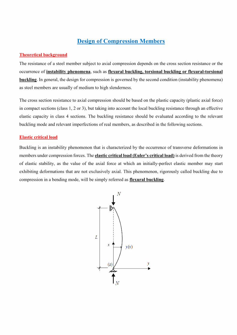
Elastic critical load
Buckling is an instability phenomenon that is characterized by the occurrence of transverse deformations in
members under compression forces. The elastic critical load (Euler’s critical load) is derived from the theory
of elastic stability, as the value of the axial force at which an initially-perfect elastic member may start
exhibiting deformations that are not exclusively axial. This phenomenon, rigorously called buckling due to
compression in a bending mode, will be simply referred as flexural buckling.
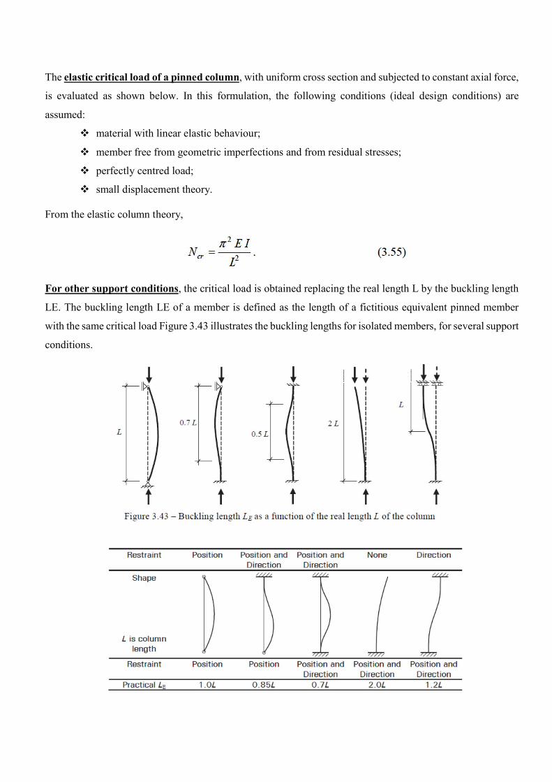
The elastic critical load of a pinned column, with uniform cross section and subjected to constant axial force,
is evaluated as shown below. In this formulation, the following conditions (ideal design conditions) are
assumed:
material with linear elastic behaviour;
member free from geometric imperfections and from residual stresses;
perfectly centred load;
small displacement theory. From the elastic column theory,
For other support conditions, the critical load is obtained replacing the real length L by the buckling length
LE. The buckling length LE of a member is defined as the length of a fictitious equivalent pinned member
with the same critical load Figure 3.43 illustrates the buckling lengths for isolated members, for several support
conditions.
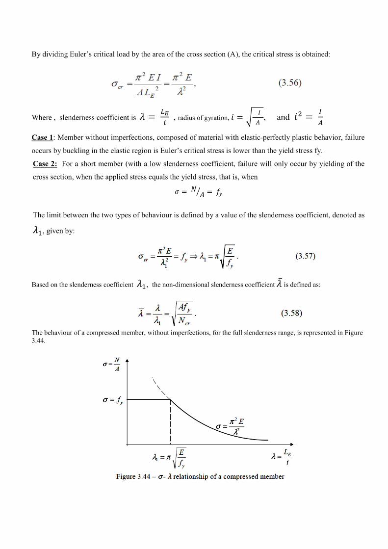
By dividing Euler’s critical load by the area of the cross section (A), the critical stress is obtained:
Where , slenderness coefficient is , radius of gyration,
, and
Case 1: Member without imperfections, composed of material with elastic-perfectly plastic behavior, failure
occurs by buckling in the elastic region is Euler’s critical stress is lower than the yield stress fy.
Case 2: For a short member (with a low slenderness coefficient, failure will only occur by yielding of the
cross section, when the applied stress equals the yield stress, that is, when
The limit between the two types of behaviour is defined by a value of the slenderness coefficient, denoted as
, given by:
Based on the slenderness coefficient , the non-dimensional slenderness coefficient ̅is defined as:
The behaviour of a compressed member, without imperfections, for the full slenderness range, is represented in Figure 3.44.
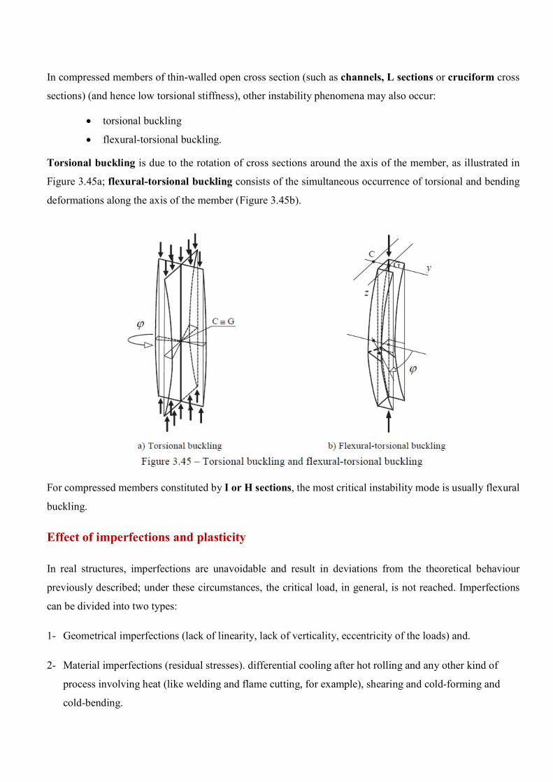
In compressed members of thin-walled open cross section (such as channels, L sections or cruciform cross
sections) (and hence low torsional stiffness), other instability phenomena may also occur:
torsional buckling
flexural-torsional buckling.
Torsional buckling is due to the rotation of cross sections around the axis of the member, as illustrated in
Figure 3.45a; flexural-torsional buckling consists of the simultaneous occurrence of torsional and bending
deformations along the axis of the member (Figure 3.45b).
For compressed members constituted by I or H sections, the most critical instability mode is usually flexural
buckling.
Effect of imperfections and plasticity
In real structures, imperfections are unavoidable and result in deviations from the theoretical behaviour
previously described; under these circumstances, the critical load, in general, is not reached. Imperfections
can be divided into two types:
1- Geometrical imperfections (lack of linearity, lack of verticality, eccentricity of the loads) and.
2- Material imperfections (residual stresses). differential cooling after hot rolling and any other kind of
process involving heat (like welding and flame cutting, for example), shearing and cold-forming and
cold-bending.
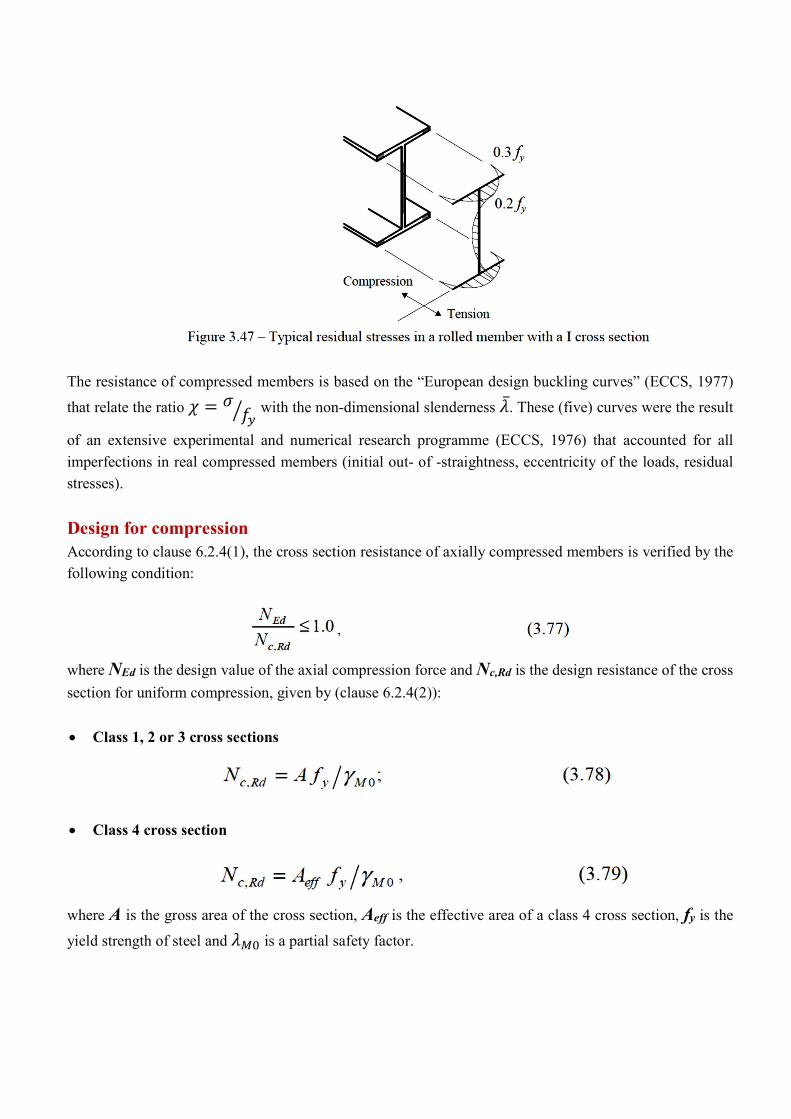
The resistance of compressed members is based on the “European design buckling curves” (ECCS, 1977)
that relate the ratio with the non-dimensional slenderness ̅. These (five) curves were the result
of an extensive experimental and numerical research programme (ECCS, 1976) that accounted for all
imperfections in real compressed members (initial out- of -straightness, eccentricity of the loads, residual
stresses).
Design for compression According to clause 6.2.4(1), the cross section resistance of axially compressed members is verified by the
following condition:
where NEd is the design value of the axial compression force and Nc,Rd is the design resistance of the cross
section for uniform compression, given by (clause 6.2.4(2)):
Class 1, 2 or 3 cross sections
Class 4 cross section
where A is the gross area of the cross section, Aeff is the effective area of a class 4 cross section, fy is the
yield strength of steel and is a partial safety factor.
In evaluating Nc,Rd , holes for fasteners can be neglected, provided they are filled by fasteners and are not
oversize (clause 6.2.4(3)).
In compression members it must also be verified that:
where Nb,Rd is the design buckling resistance of the compression member (clause 6.3.1.1(1)) and this
generally controls design. The design flexural buckling resistance of prismatic members is given by:
Class 1, 2 or 3 cross sections
Class 4 cross sections
Where is the reduction factor for the relevant buckling mode and is a partial safety factor (clause
6.3.1.1(3)). The reduction factor is obtained from the following equation:
where
Where is the non dimensional slenderness coefficient, given by:
Class 1, 2 or 3 cross sections
Class 4 cross sections
where, is the imperfection factor; Ncr is the elastic critical load (Euler’s critical load) for the relevant buckling mode;
ET is the tangent modulus Lcr is the length of the corresponding buckling mode;
i is the radius of gyration of the cross section;
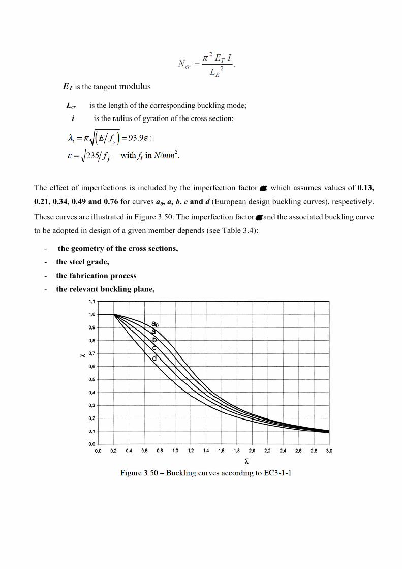
The effect of imperfections is included by the imperfection factor , which assumes values of 0.13,
0.21, 0.34, 0.49 and 0.76 for curves a0, a, b, c and d (European design buckling curves), respectively.
These curves are illustrated in Figure 3.50. The imperfection factor and the associated buckling curve
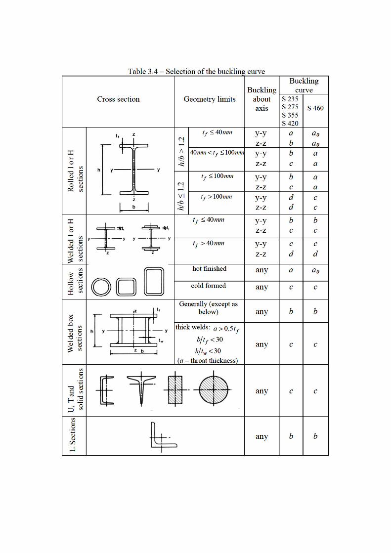
to be adopted in design of a given member depends (see Table 3.4):
- the geometry of the cross sections,
- the steel grade,
- the fabrication process
- the relevant buckling plane,
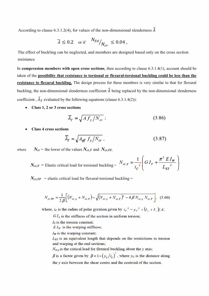
According to clause 6.3.1.2(4), for values of the non-dimensional slenderness
0.2 or if
0.04 ,
The effect of buckling can be neglected, and members are designed based only on the cross section
resistance.
In compression members with open cross sections, then according to clause 6.3.1.4(1), account should be
taken of the possibility that resistance to torsional or flexural-torsional buckling could be less than the
resistance to flexural buckling. The design process for these members is very similar to that for flexural
buckling, the non-dimensional slenderness coefficient being replaced by the non-dimensional slenderness
coefficient , ̅ evaluated by the following equations (clause 6.3.1.4(2)):
Class 1, 2 or 3 cross sections
Class 4 cross sections
where Ncr = the lower of the values Ncr,T and Ncr,TF.
Ncr,T = Elastic critical load for torsional buckling =
Ncr,TF = elastic critical load for flexural-torsional buckling =