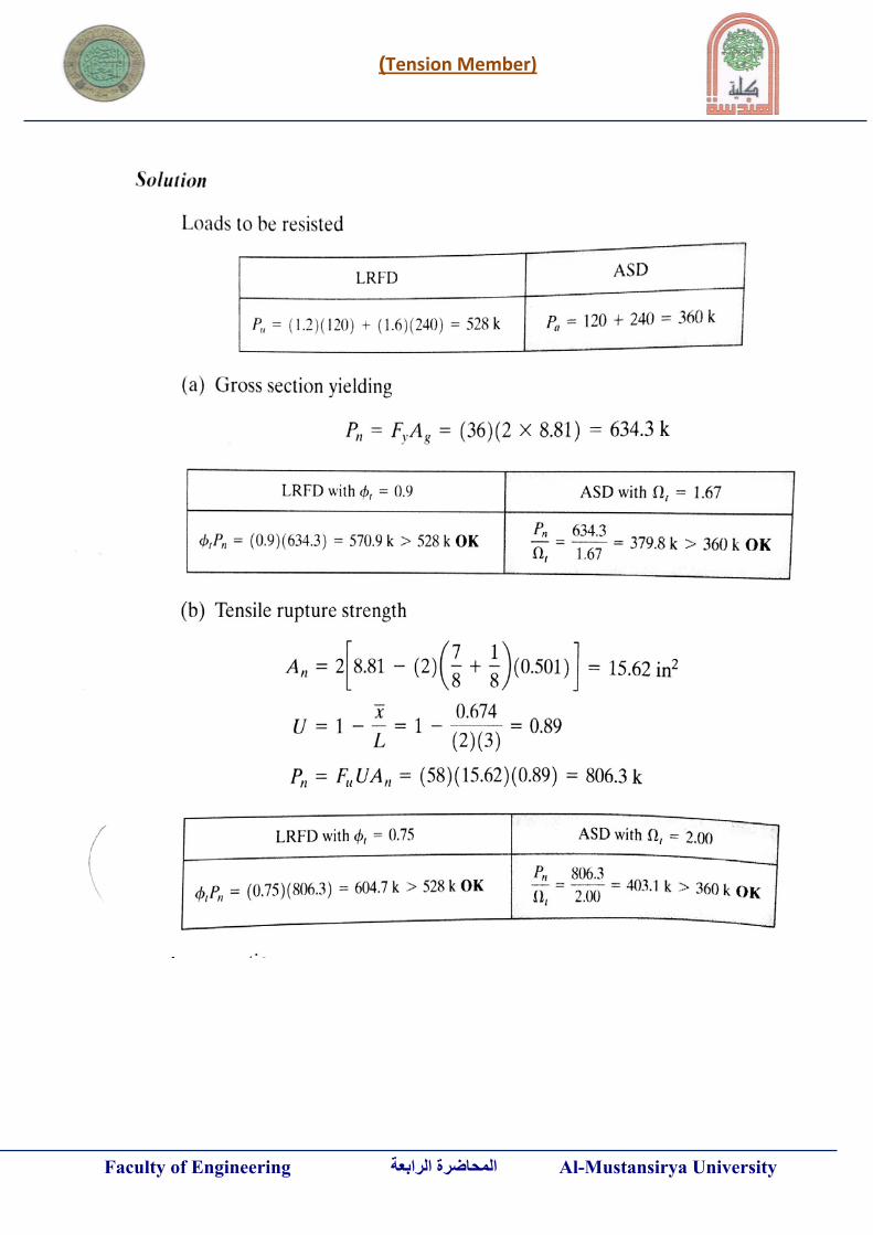
structural steel design tension members -4-
TRANSCRIPT
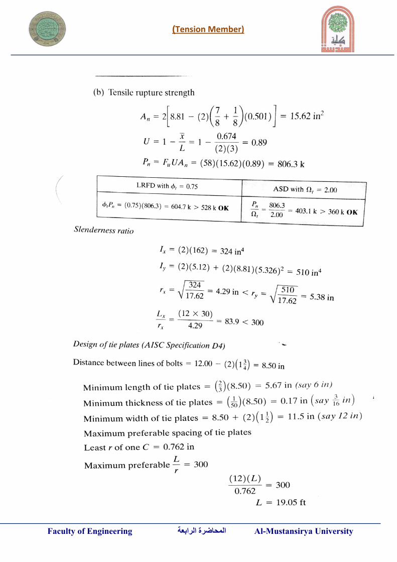
Tension Member)(
Faculty of Engineering الرابعةالمحاضرة Al-Mustansirya University
STRUCTURAL STEEL DESIGN
Tension Members -4-
Dr.Mu'taz K.M Lecture in Civil Engineering
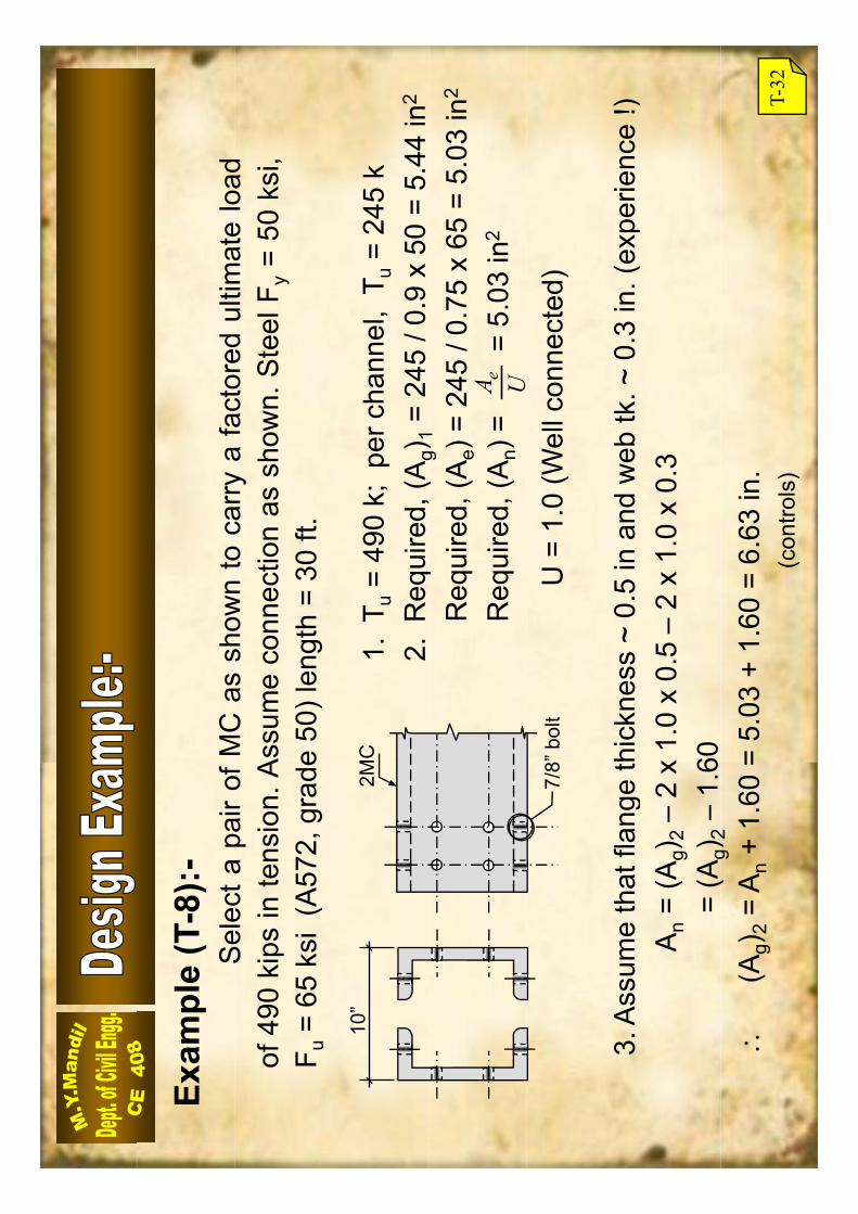
Sel
ecta
pair
ofM
Cas
show
nto
carry
afa
ctor
edul
timat
elo
adEx
ampl
e (T
-8):-
Sel
ecta
pair
ofM
Cas
show
nto
carry
afa
ctor
edul
timat
elo
adof
490
kips
inte
nsio
n.A
ssum
eco
nnec
tion
assh
own.
Ste
elF y
=50
ksi,
F u=
65ks
i(A
572,
grad
e50
)len
gth
=30
ft.
1.T u
= 49
0 k;
per
cha
nnel
, T u
= 24
5 k
2.R
e qui
red,
(Ag)
1=
245
/ 0.9
x 50
= 5.
44 in
2
10”
2MC
q,(
g)1
Req
uire
d, (A
e) =
245
/ 0.
75 x
65
= 5.
03 in
2
Req
uire
d, (A
n) =
= 5
.03
in2
UA e
3A
ssum
eth
atfla
nge
thic
knes
s~
05
inan
dw
ebtk
~0
3in
(exp
erie
nce
!)
7/8”
bol
tU
= 1
.0 (W
ell c
onne
cted
)
3.A
ssum
eth
atfla
nge
thic
knes
s~
0.5
inan
dw
ebtk
.~0.
3in
.(ex
perie
nce
!)A
n=
(Ag)
2–
2 x
1.0
x 0.
5 –
2 x
1.0
x 0.
3=
(Ag)
2–
1.60
(g)
2
(Ag)
2=
An
+ 1.
60 =
5.0
3 +
1.60
= 6
.63
in.
(con
trols
)T-
32
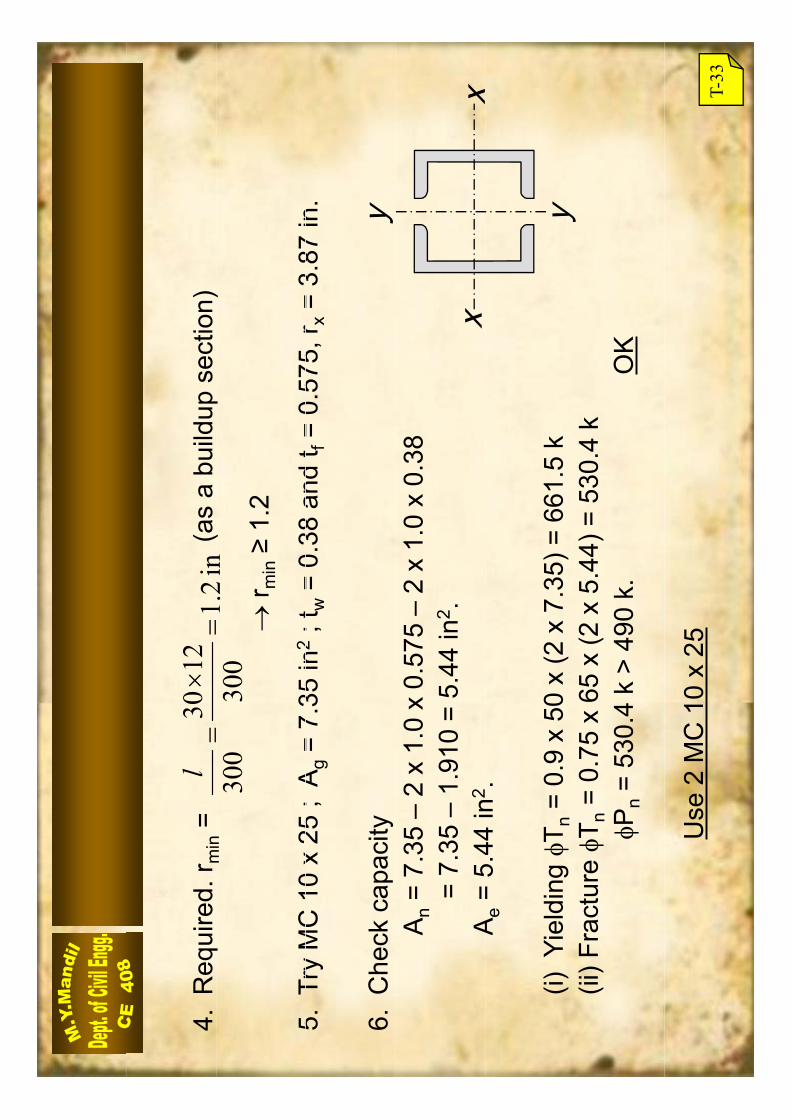
4.R
equi
red.
r min
=
(a
s a
build
up s
ectio
n)in
21
1230
lq
min
(p
)
5Tr
yM
C10
x25
;A
=7
35in
2;t
=0
38an
dt
=0
575
r=
387
in
in2.1
300
300
r min
1.2
5.Tr
yM
C10
x25
;A
g=
7.35
in2
;tw
=0.
38an
dt f
=0.
575,
r x=
3.87
in.
6.C
heck
cap
acity
yA
n=
7.35
–2
x 1.
0 x
0.57
5 –
2 x
1.0
x 0.
38=
7.35
–1.
910
= 5.
44 in
2 .A
=5
44in
2x
xA
e=
5.44
in.
(i) Y
ield
ing
T n=
0.9
x 50
x (2
x 7
.35)
= 6
61.5
ky
(ii) F
ract
ure
T n=
0.75
x 65
x (2
x 5.
44) =
530
.4k
Pn
= 53
0.4
k >
490
k.
OK
y
Use
2 M
C 1
0 x
25T-
33
Tension Member)(
Faculty of Engineering الرابعةالمحاضرة Al-Mustansirya University
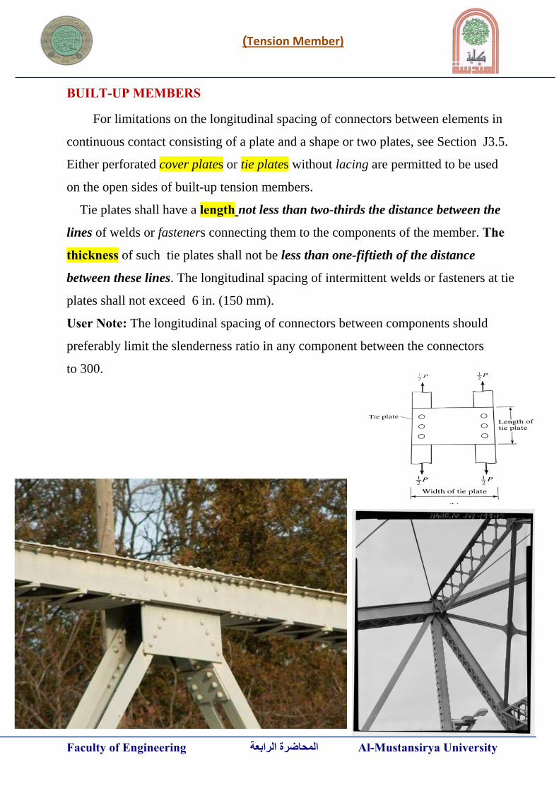
BUILT-UP MEMBERS For limitations on the longitudinal spacing of connectors between elements in
continuous contact consisting of a plate and a shape or two plates, see Section J3.5.
Either perforated cover plates or tie plates without lacing are permitted to be used
on the open sides of built-up tension members.
Tie plates shall have a length not less than two-thirds the distance between the
lines of welds or fasteners connecting them to the components of the member. The
thickness of such tie plates shall not be less than one-fiftieth of the distance
between these lines. The longitudinal spacing of intermittent welds or fasteners at tie
plates shall not exceed 6 in. (150 mm).
User Note: The longitudinal spacing of connectors between components should
preferably limit the slenderness ratio in any component between the connectors
to 300.

Tension Member)(
Faculty of Engineering الرابعةالمحاضرة Al-Mustansirya University
Tension Member)(
Faculty of Engineering الرابعةالمحاضرة Al-Mustansirya University
Tension Member)(
Faculty of Engineering الرابعةالمحاضرة Al-Mustansirya University

BOLTS AND THREADED PARTSSect. J3.] 16.1-107
TABLE J3.4Minimum Edge Distance,[a] in., from
Center of Standard Hole[b] to Edge ofConnected Part
At Rolled Edges ofPlates,
Shapes or Bars, orBolt Diameter (in.) At Sheared Edges Thermally Cut Edges [c]
1/2 7/8 3/45/8 11/8 7/83/4 11/4 17/8 11/2 [d] 11/8
1 13/4 [d] 11/4
11/8 2 11/2
11/4 21/4 15/8
Over 11/4 13/4 × d 11/4 × d[a] Lesser edge distances are permitted to be used provided provisions of Section J3.10, as appro-priate, are satisfied.[b] For oversized or slotted holes, see Table J3.5.[c] All edge distances in this column are permitted to be reduced 1/8 in. when the hole is at a pointwhere required strength does not exceed 25 percent of the maximum strength in the element.[d] These are permitted to be 11/4 in. at the ends of beam connection angles and shear end plates.
TABLE J3.4MMinimum Edge Distance,[a] mm, fromCenter of Standard Hole[b] to Edge of
Connected PartAt Rolled Edges of
Plates,Shapes or Bars, or
Bolt Diameter (mm) At Sheared Edges Thermally Cut Edges [c]
16 28 2220 34 2622 38 [d] 2824 42 [d] 3027 48 3430 52 3836 64 46
Over 36 1.75d 1.25d[a] Lesser edge distances are permitted to be used provided provisions of Section J3.10, as appro-priate, are satisfied.[b] For oversized or slotted holes, see Table J3.5M.[c] All edge distances in this column are permitted to be reduced 3 mm when the hole is at a pointwhere required strength does not exceed 25 percent of the maximum strength in the element.[d] These are permitted to be 32 mm at the ends of beam connection angles and shear end plates.
Specification for Structural Steel Buildings, March 9, 2005AMERICAN INSTITUTE OF STEEL CONSTRUCTION, INC.