collegiate design series baja sae rules revision a 16
TRANSCRIPT
Collegiate Design Series Baja SAE
® Rules
2022 Revision A
16 August 2021
Page 2, Revision A – 2021/08/16
Foreword
Welcome to Baja SAE® 2022!
For the 2022 season, there are a number of significant rule changes which warrant some explanation of
rationale. For the complete list of rule changes, see the next section, as well as the proposed rule
changes for the 2023 season. The following are the major changes for 2022 competitions:
Business Presentation
Business Presentation (BP) will operate in a hybrid model compiled of virtual and onsite presentations.
The points have increased from 50 to 70 points, while each of the dynamic events (minus the Endurance
event) has decreased from 75 to 70 points. All teams will virtually present their BP to a panel of judges
and their score will apply to all onsite competitions they are attending. Teams will be ranked only against
teams attending the same competition. The virtual presentations will take place before any onsite events.
Based on virtual scores, the top scoring BP teams for each onsite competition will then present to a live
judge panel in-person at the respective event, for the opportunity to earn bonus points. The change to a
hybrid presentation lessens the burden on student teams at onsite events, while still providing an
educational and real-world learning experience, as today’s business is handled more and more in a digital
and virtual format.
Drivetrain Vent Lines
While reviewing vehicles from previous seasons, attention has been drawn to drivetrain components and
the fluids contained therein. While conducting this review the BSAE Rules Committee decided that proper
venting of drivetrain components was required in order to minimize the environmental and safety
concerns that can arise from improperly vented drivetrain components. The new rule designed to ensure
safe venting of drivetrain components, and minimizing spilled fluids in the event of a vehicle rollover.
Page 3, Revision A – 2021/08/16
Baja SAE® 2022 - List of Rule Changes
Caution: The following is not an exhaust ive l ist of the rule changes. Neither this
l ist of updates and changes nor any summary is a substitute for thoroughly
reading and understanding the rules. Teams should regularly check
www.bajasae.net/go/news for news and updates.
Teams are required to read and comprehend the rules. Read the rules early and
often.
A.1.4 - Design Subject – 4WD/AWD requirement updated.
B.1.5.2 – Four-Wheel Drive / All-Wheel Drive requirement updated.
B.1.7 – Technology Challenge added.
B.2.7.13.7 – Muffler Cage now required.
B.3.2.13.2 – Rear Bracing angle updated regarding Point A.
B.4.2.5.1 – Lap Belt positioning updated to match SFI recommendations.
B.4.3.2 – Expiration updated to delete arm restraint expiration dates.
B.4.5.3.1 – Quantity updated to clarify 1/4" fasteners are the minimum for seats.
B.5.3.2 – Expiration updated to delete neck support expiration dates.
B.6.5.1 – Mounting updated to clarify fuel tank fastener stack-up requirements.
B.6.6.1 – Location multiple updates for fuel line requirement.
B.6.6.4 – Fuel Filters updated location requirements.
B.6.7 – Splash Shields updated for clarity.
B.6.9 – Fuel Tank Access Panels updated to require fuel tank to be visible.
B.7.1 – Brake System requirements updated for use with 4WD.
B.7.3.1 - Compressed Gas Systems updated for clarity on scope of use.
B.8.3 – Firewall updated regarding drivetrain penetrations.
Article 9 – Powertrain Guards rule has a major update. Carefully review the entire section.
B.10.3.2 – Required Switch updated to only allow these switches for kill switch use.
Page 4, Revision A – 2021/08/16
B.10.3.3.1 – Cockpit Switch updated to not allow other switches in the vicinity of the kill switch.
C.3.4.4 – Design Finals updated format, design comparison, and bonus points.
C.4.2.4 – Cost Reduction Report added.
C.5.5 – Business Presentation Format updated.
Part D : Dynamic Events – Scoring updated.
Baja SAE® 2023 - Proposed Rule Changes 1. 4WD/AWD vehic les only. 2WD vehic les not a l lowed.
Page 5, Revision A – 2021/08/16
Table of Contents
Table of Contents ...................................................................................................................... 5
Part A : Administrative Regulations ........................................................................................... 8
Article 1 - Baja SAE® Overview ................................................................................................................ 8
Article 2 - Competition Information............................................................................................................ 9
Article 3 - Rules and Organizer Authority ............................................................................................... 10
Article 4 - Participation Requirements .................................................................................................... 13
Article 5 - Vehicle Eligibility ..................................................................................................................... 15
Article 6 - Registration ............................................................................................................................. 15
Article 7 - Report Submission ................................................................................................................. 17
Part B : Technical Requirements ............................................................................................. 19
Article 1 - General Design Requirements ............................................................................................... 19
Article 2 - Engine ..................................................................................................................................... 20
Article 3 - Roll Cage ................................................................................................................................ 25
Article 4 - Driver Restraint ....................................................................................................................... 47
Article 5 - Driver Equipment .................................................................................................................... 59
Article 6 - Fuel System ............................................................................................................................ 61
Article 7 - Vehicle Controls ...................................................................................................................... 66
Article 8 - Cockpit .................................................................................................................................... 69
Article 9 - Powertrain Guards .................................................................................................................. 74
Article 10 - Electrical System .................................................................................................................. 79
Article 11 - Tow Points ............................................................................................................................ 82
Article 12 - Fasteners .............................................................................................................................. 84
Article 13 - Vehicle Identification and Markings ...................................................................................... 86
Part C : Static Events............................................................................................................... 94
Article 1 - Scoring Summary ................................................................................................................... 94
Article 2 - Technical Inspection ............................................................................................................... 94
Article 3 - Design Evaluation ................................................................................................................... 96
Article 4 - Cost Evaluation ....................................................................................................................... 99
Article 5 - Business Presentation (BP) .................................................................................................. 101
Part D : Dynamic Events........................................................................................................ 103
Article 1 - Scoring Summary ................................................................................................................. 103
Article 2 - Practice ................................................................................................................................. 103
Article 3 - Acceleration .......................................................................................................................... 104
Article 4 - Traction ................................................................................................................................. 105
Article 5 - Maneuverability ..................................................................................................................... 107
Article 6 - Specialty Events ................................................................................................................... 108
Article 7 - Endurance ............................................................................................................................ 109
Article 8 - General Event Procedures and Regulations ........................................................................ 115
Part E : Appendices ............................................................................................................... 126
Article 1 - SAE Technical Standards ..................................................................................................... 126
Article 2 - List of Abbreviations ............................................................................................................. 128
Page 6, Revision A – 2021/08/16
Table of Figures Figure B-1: Engine, Governor, B&S Model 19 ........................................................................................................ 23
Figure B-2: Roll Cage, Bend and Member Termination .......................................................................................... 26
Figure B-3: Roll Cage, Primary Members (filled in black), Front Braced Frame ..................................................... 27
Figure B-4: Roll Cage, Primary Members (filled in black), Rear Braced Frame...................................................... 27
Figure B-5: Roll Cage Example, Named Points, ‘Nose; Car with Rear Bracing. .................................................... 28
Figure B-6: Roll Cage Example, Named Points, Front Bracing .............................................................................. 29
Figure B-7: Roll Cage, LC ....................................................................................................................................... 30
Figure B-8: Roll Cage, RRH .................................................................................................................................... 31
Figure B-9: Roll Cage, LDB ..................................................................................................................................... 32
Figure B-10: Roll Cage, RHO .................................................................................................................................. 33
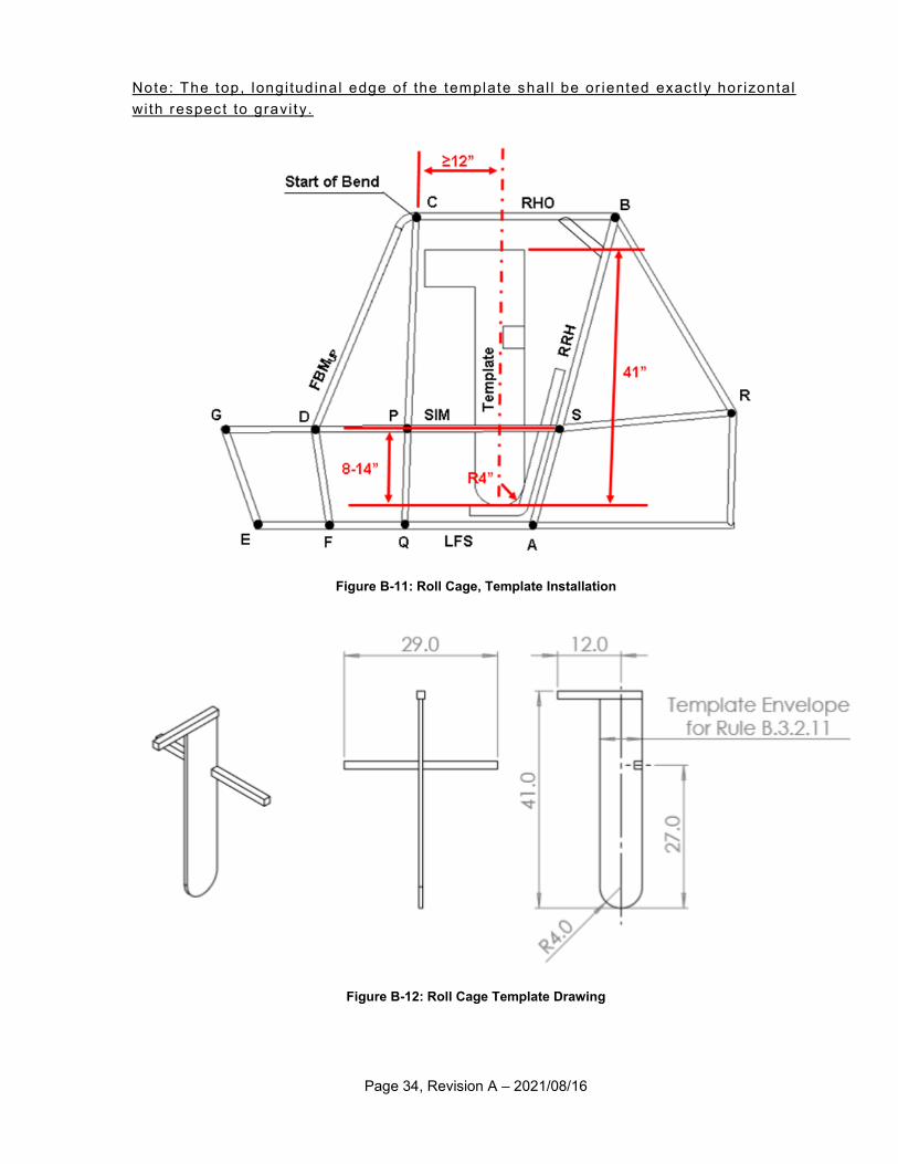
Figure B-11: Roll Cage, Template Installation ......................................................................................................... 34
Figure B-12: Roll Cage Template Drawing .............................................................................................................. 34
Figure B-13: Roll Cage, Gussets ............................................................................................................................. 35
Figure B-14: Roll Cage ‘Nose’ Example, LFS ......................................................................................................... 36
Figure B-15: Roll Cage ‘Nose’ Example, SIM ......................................................................................................... 37
Figure B-16: Roll Cage ‘Nose’ Example, USM ........................................................................................................ 38
Figure B-17: Roll Cage, FBM .................................................................................................................................. 39
Figure B-18: RHO / FBM Gussets ........................................................................................................................... 40
Figure B-19: Roll Cage, FAB ................................................................................................................................... 41
Figure B-20: Roll Cage, Butt Joint Sleeve ............................................................................................................... 42
Figure B-21: Roll Cage, Welding Sample 1 ............................................................................................................. 43
Figure B-22: Roll Cage, Welding Sample 2 ............................................................................................................. 43
Figure B-23: Roll Cage, Required Joint for Removable Members .......................................................................... 46
Figure B-24: Roll Cage, Required sleeve for drilled holes ...................................................................................... 46
Figure B-25: Driver Harness Schematic .................................................................................................................. 48
Figure B-26: Driver Harness, SFI Tag, Old Style (Left), New Style (Right)............................................................. 49
Figure B-27: Driver Harness, Shoulder Harness Vertical Position .......................................................................... 50
Figure B-28: Driver Harness, Shoulder Harness Lateral Position ........................................................................... 50
Figure B-29: Driver Harness, Shoulder Harness Lateral Restraint ......................................................................... 51
Figure B-30: Driver Harness, Diagram of Proper Wrapping of Webbing ................................................................ 51
Figure B-31: Driver Harness, Lap Belt Angle .......................................................................................................... 53
Figure B-32: Driver Harness, Lap Belt Tab Orientation ........................................................................................... 53
Figure B-33: Driver Harness, Anti-Submarine Belt Angle ....................................................................................... 55
Figure B-34: Driver Harness, Anti-Submarine Belt Redirection ............................................................................. 56
Figure B-35: Driver Harness, Arm Restraints ......................................................................................................... 57
Figure B-36: Seat Angle .......................................................................................................................................... 58
Figure B-37: Driver Equipment, Example Snell Sticker ........................................................................................... 59
Figure B-38 : Driver Equipment, Example ECE Tags ............................................................................................. 59
Figure B-39: Driver Equipment, Neck Support ........................................................................................................ 60
Figure B-40: Fuel Tank Fastener Stack-up ............................................................................................................. 62
Figure B-41: Fuel tank mounted to square/rectangular tubes (preferred mounting design) ................................... 63
Figure B-42: Fuel tank mounted to "C" brackets. (Acceptable mounting design) ................................................... 63
Figure B-43: Allowable Taper .................................................................................................................................. 64
Page 7, Revision A – 2021/08/16
Figure B-44: Minimum weld length .......................................................................................................................... 64
Figure B-45: Fuel System, Splash Guard Installation Example .............................................................................. 66
Figure B-46: Throttle Cable Exit Angle .................................................................................................................... 68
Figure B-47: Incorrect orientation of extinguisher clamps. ...................................................................................... 73
Figure B-48: Incorrect routing of hose clamps. ....................................................................................................... 73
Figure B-49: Fire Extinguisher, Diagram of Clearance around Pull Knob (green) .................................................. 74
Figure B-50: Powertrain Guard Extent example on a CVT ..................................................................................... 75
Figure B-51: Powertrain Guard Example................................................................................................................. 76
Figure B-52: Air Trap Vent Line Routing ................................................................................................................. 77
Figure B-53: Driveshaft Guarding ............................................................................................................................ 78
Figure B-54: Engine Kill Switch Mounting Position ................................................................................................. 80
Figure B-55: Tow Point, Inspection Tool Fitment .................................................................................................... 83
Figure B-56: Tow Point, Table of Tow Point Dimensions ........................................................................................ 83
Figure B-57: Tow Point, Rear Tab Dimensions ....................................................................................................... 84
Figure B-58: Fasteners, acceptable markings ......................................................................................................... 85
Figure B-59: Required Tab Drawing ........................................................................................................................ 86
Figure B-60 : Tab Requirements ............................................................................................................................. 86
Figure B-61: List of approved and unapproved transponders. ................................................................................ 87
Figure B-62: Chart of transponder information ........................................................................................................ 88
Figure B-63: Transponder Orientation ..................................................................................................................... 89
Figure B-64: Transponder, Mounting Location ........................................................................................................ 89
Figure B-65 : Approved vehicle number font examples. ......................................................................................... 90
Figure B-66: Vehicle Numbers, Example ................................................................................................................ 91
Figure B-67: RFID Tag Dimensions ........................................................................................................................ 92
Figure B-68: RFID tag location ................................................................................................................................ 93
Figure C-1: Static Events, Table of Points .............................................................................................................. 94
Figure D-1: Dynamic Events, Table of Points ....................................................................................................... 103
Figure D-2: Endurance Event, Table of Penalties ................................................................................................. 113
Figure D-3: Endurance Event, Table of Bonus Points ........................................................................................... 114
Figure D-4: Signals and Signage, Green Flag ...................................................................................................... 120
Figure D-5: Signals and Signage, Yellow Flag ...................................................................................................... 120
Figure D-6: Signals and Signage, Red Flag .......................................................................................................... 121
Figure D-7: Signals and Signage, Black Flag ........................................................................................................ 121
Figure D-8: Signals and Signage, Checkered Flag ............................................................................................... 122
Figure D-9: Signals and Signage, Directional Arrow ............................................................................................. 122
Figure D-10: Signals and Signage, Control Zone Boundary ................................................................................. 122
Figure D-11: Signals and Signage, Time Control Marshal .................................................................................... 123
Figure D-12: Signals and Signage, Start Line ....................................................................................................... 123
Figure D-13: Signals and Signage, Finish Line ..................................................................................................... 124
Figure D-14: Signals and Signage, Stop Sign ....................................................................................................... 124
Figure D-15: Signals and Signage, End Control Zone .......................................................................................... 124
Figure D-16: Signals and Signage, Begin Fuel Zone ............................................................................................ 125
Figure D-17: Signals and Signage, End Fuel Zone ............................................................................................... 125
Figure D-18: Signals and Signage, Begin Service Area ........................................................................................ 125
Figure D-19: Signals and Signage, End Service Area .......................................................................................... 126
Page 8, Revision A – 2021/08/16
Part A : Administrative Regulations
Article 1 - Baja SAE® Overview
A.1.1 - Program History
The Baja SAE® competition series originated at the University of South Carolina in 1976, under the
direction of Dr. John F. Stevens. Since that time, the Baja SAE® Series has grown to become a premier
engineering design series for university teams.
A.1.2 - Collegiate Design Series Objective
SAE International’s Collegiate Design Series (CDS) programs prepare undergraduate and graduate
engineering students in a variety of disciplines for future employment in mobility-related industries by
challenging them with a real world, engineering application.
Through the Engineering Design Process, experiences may include, but are not limited to:
Project management, budgeting, communication, and resource management skills
Team collaboration
Applying industry rules and regulations
Design, build, and test the performance of a real vehicle
Compete with other students from around the globe
Develop and prepare technical documentation
Students also gain valuable exposure to and engagement with industry professionals to enhance 21st
century learning skills, to build their own network, and help prepare them for the workforce after
graduation.
A.1.3 - Baja SAE Program Objective
Baja SAE® is an intercollegiate engineering design competition for undergraduate and graduate
engineering students. The object of the competition is to simulate real-world engineering design projects
and their related challenges. Each team is competing to have its design accepted for manufacture by a
fictitious firm. The students must function as a team to design, engineer, build, test, promote and compete
with a vehicle within the limits of the rules. They must also generate financial support for their project and
manage their educational priorities.
A.1.4 - Design Subject
Each team's goal is to design and build a single-seat, all-terrain, sporting vehicle whose driver is
contained within the structure of the vehicle. The vehicle is to be a prototype for a reliable, maintainable,
ergonomic, and economic production vehicle which serves a recreational user market, sized at
approximately 4,000 units per year. The vehicle should aspire to market-leading performance in terms of
speed, handling, ride, and ruggedness over rough terrain and off-road conditions. Performance will be
measured by success in the static and dynamic events which are described in the Baja SAE® Rules, and
are subject to event-site weather and course conditions.
Page 9, Revision A – 2021/08/16
For all 2023 competitions, BSAE vehicles will be required to have 4-wheel drive (4WD) or all-wheel-drive
(AWD). For 2022 competitions, vehicles designed and built with a robust, functional 4WD/AWD system
will receive bonus points to their overall score.
Article 2 - Competition Information
A.2.1 - Competitions
SAE International will host up to three competitions within the United States and Canada in a given
competition year. Locations will change yearly and are dependent on local support of SAE Sections,
Universities, and Sponsor Companies.
Competitions outside the US and Canada include:
Baja SAE Brazil, hosted by SAE Brazil
Baja SAE Korea, hosted by Yeungnam University
Baja SAE South Africa, sponsored by Sasol and hosted by Gerotek Test Facility
Baja SAE Mexico, hosted by SAE Mexico
A.2.2 - Official Announcements
Teams are required to read the articles posted on www.bajasae.net/go/news published by SAE
International and the other organizing bodies. Teams must also be familiar with all official announcements
concerning Rules Clarifications released on the Downloads page on BajaSAE.net
A.2.3 - Official Languages
The official language of the Baja SAE® Series is English. Document submissions, presentations and
discussions in English are acceptable at all competitions in the series. Team members, judges, and
officials at non-U.S. competition events may use their respective national languages for document
submissions, presentations and discussions if all the parties involved agree to the use of that language.
A.2.4 - SAE International Technical Standards Access
A cooperative program of SAE International’s Education Board and Technical Standards Board is making
some of SAE International’s Technical Standards available to teams registered for any US and Canadian
Collegiate Design Series (CDS) competition at no cost. The Technical Standards referenced in the CDS
rules, along with other standards with reference value, will be accessible online to registered teams, team
members and faculty advisors. A list of accessible SAE Technical Standards can be found in the
appendices, Part E : Article 1 - SAE Technical Standards.
A.2.4.1 - Eligibility
To access the standards your team must be registered for a competition in North America and the
individual team member or faculty advisor wanting access must be affiliated to the team on SAE
International’s website (www.sae.org).
A.2.4.2 - Access Procedure
Once registered, a link to SAE MOBILUS will appear to access the technical standards under “Design
Standards” on your team’s profile page on sae.org, where all the required onsite team information is
added. On SAE MOBILUS, you will have the ability to search standards either by J-number assigned or
topic of interest such as brake light.
Page 10, Revision A – 2021/08/16
Article 3 - Rules and Organizer Authority
A.3.1 - Rules Authority
The Baja SAE® Rules are the responsibility of the Baja SAE® Rules Committee and are issued under the
authority of the SAE International. Official announcements from the Baja SAE® Rules Committee, SAE
International, National Technical Inspectors (NTI) or the other Baja SAE® Organizers shall be considered
part of and have the same validity as these rules. Ambiguities or questions concerning the meaning or
intent of these rules will be resolved by the Baja SAE® Rules Committee, National Technical Inspectors,
or SAE International Staff during competition onsite.
A.3.2 - Rules Variation
Some sections of rules governing Baja SAE® events held outside the U.S. and Canada are specific to
these competitions. Such variations are published on the individual websites.
A.3.3 - Rules Validity
The newest revision of the Baja SAE® Rules posted on the BajaSAE.net website and dated for the
calendar year of the competition are the rules in effect for the competition. Rule sets dated for other years
or older versions of the current year are invalid.
A.3.4 - Rules Compliance
By entering a Baja SAE® competition, the team members, faculty advisors and other personnel of the
entering university agree to comply with, and be bound by, the rules and all rules interpretations or
procedures issued or announced by SAE International, the Baja SAE® Rules Committee and other
organizing bodies. All team members, faculty advisors and other university representatives are required
to cooperate with, and follow all instructions from competition organizers, officials and judges.
A.3.5 - Rules Comprehension
Teams are responsible for reading, understanding and comprehending the rules in their entirety for the
competition in which they are participating. The section and paragraph headings in these rules are
provided to facilitate reading: they do not fully explain all the paragraph contents. Questions regarding
rules may be submitted by registered users through the rules inquiry feature on BajaSAE.net.
A.3.5.1 - Rules Quiz
Briggs and Stratton engine inspection numbers may be assigned by SAE after completion of a rules
comprehension quiz.
A.3.6 - Rules Questions
A.3.6.1 - Privacy
By submitting a rules inquiry on BajaSAE.net, the submitter agrees that both question and the NTI’s
answer can be reproduced and distributed by SAE International, in edited versions, in any medium or
format anywhere in the world.
Page 11, Revision A – 2021/08/16
A.3.6.2 - Duplication
The National Technical Inspectors (NTI) will answer questions that are not already answered in the rules
or FAQs or that require new or novel rule interpretations. For example, if a rule specifies a minimum
dimension for a part, the NTI’s will not answer questions asking if a smaller dimension can be used.
A.3.6.3 - Submission
An electronic question submission system has been developed for the North American competitions. The
current submission instructions are published on BajaSAE.net, accessible by clicking “Submit a Rules
Question.”
A.3.6.4 - Documentation
Teams submitting questions are required to bring copies of the questions and answers with them to
technical inspection.
A.3.6.5 - Response Time
Please allow a minimum of two (2) weeks for a response. The National Technical Inspectors (NTI) will
respond as quickly as possible. However, responses to questions presenting new issues, or of unusual
complexity, may take more than two weeks.
Note: Please keep in mind that f ina l operat ing approval of any Baja SAE ® vehic le can
only be g iven ons i te at the compet it ion.
A.3.7 - Loopholes
It is virtually impossible for a set of rules to be so comprehensive that it covers all possible questions
about the vehicle’s design parameters or the conduct of the competition. Please keep in mind that safety
remains paramount during Baja SAE®, so any perceived loopholes should be resolved in the direction of
increased safety of the competition.
A.3.8 - Participating in the Competition
Teams, team members as individuals, faculty advisors and other representatives of a registered university
who are present onsite at a competition are “participating in the competition” from the time they arrive at
the event site until they depart the site at the conclusion of the competition or earlier by withdrawing. All
team members and faculty advisors are required to register with their team as part of their Fast Track
Roster (Liability Waiver) and obtain a liability wristband at the registration table onsite. The Fast Track
Roster can be found on your team profile page at www.sae.org. Your Fast Track Roster must be printed,
signed by all team members, and brought to competition after finalized. Please note: Team members that
are attending and not attending competition should be included on the Fast Track Roster.
A.3.9 - Violations of Intent
The violations of the intent of a rule will be considered a violation of the rule itself. Questions about the
intent or meaning of a rule may be addressed to NTI or SAE International staff.
A.3.10 - Right to Impound
SAE International and the other competition organizing bodies reserve the right to impound any onsite
registered vehicle at any time during a competition for inspection and examination by the organizers,
officials and technical inspectors.
Page 12, Revision A – 2021/08/16
A.3.11 - General Authority
SAE International and the competition organizing bodies reserve the right to revise the schedule of any
competition and/or interpret or modify the competition rules at any time and in any manner, that is, in their
sole judgment, required for the safe and efficient operation of the event or the Baja SAE® series as a
whole.
A.3.12 - Protests and Appeals
It is recognized that hundreds of hours of work are put into the design and construction of a vehicle. In
the heat of competition, emotions may peak and disputes can arise. The organizers and SAE
International staff will make every effort to fully review all questions and resolve problems quickly and
efficiently.
A.3.12.1 - Preliminary Review
If a team has a question about scoring, judging, policies or any official action it must be brought to the
Baja SAE® Program Manager’s attention for an informal preliminary review.
If a team has a question about one of their results/scores they can file a Problem Report using the
mobile.bajasae.net website while at the competition site. Additional details about how to file a Problem
Report will be available at the competition site or on mobile.bajasae.net. A Problem Report is not a formal
protest but should be initiated prior to a formal protest if possible.
A.3.12.2 - Cause
A team may protest any rule interpretation, score or official action (unless specifically excluded from
protest) which they feel has caused some actual, non-trivial harm to their team, or has had a substantive
effect on their score. Teams may not protest rule interpretations or actions that have not caused them
any substantive damage.
A.3.12.3 - Format and Forfeit
All protests must be filed in writing and presented to the Baja SAE® Program Managers by the team
captain or a designated student team member. In order to have a protest considered, a team must post a
twenty-five (25) point protest bond, which will be forfeited if the protest is rejected.
Note: SAE Internat ional staf f , judges or volunteers will not review any video
footage as part of the protest.
A.3.12.4 - Protest Period
Protests concerning any aspect of the competition must be filed within 30 minutes of the end of the event
to which the protest relates.
A.3.12.5 - Decision
The decision regarding any protest is final.
Page 13, Revision A – 2021/08/16
Article 4 - Participation Requirements
A.4.1 - Students
A.4.1.1 - Eligibility
Eligibility to compete is limited to undergraduate and graduate students to ensure this is an engineering
competition rather than a race. Individual members of teams participating in this competition must satisfy
the following requirements:
A.4.1.2 - Student Status
Team members must be enrolled as a degree seeking undergraduate or graduate student in a college or
university. Team members who have graduated during the last seven (7) month period prior to the
competition remain eligible to participate.
A.4.1.3 - Society Membership
Team members must be members of at least one of the following societies:
SAE International or an SAE International affiliate society
ATA
IMechE
VDI
Proof of membership, such as a membership card, may be required at the event registration and check-
in.
Students who are members of one of the societies listed above are not required to join any of the other
societies in order to participate in any SAE International competition, but they must have a Customer
Account on SAE.org. For more information, please contact [email protected]. Those
interested may join SAE International at: http://www.sae.org/participate/members/join.
A.4.1.4 - Age
Team members must be at least eighteen (18) years of age at the time of the competition.
A.4.1.5 - Driver’s License
Team members who will drive a competition vehicle at any time during a competition must hold a valid,
government issued driver’s license. All drivers must present their driver’s license at the time of Technical
Inspection.
A.4.1.6 - Fast Track Liability Waiver
All onsite participants and faculty are required to sign their team’s Fast Track Roster (liability waiver) prior
to or upon registering onsite.
A.4.1.7 - Insurance
Individual medical and accident insurance coverage is required and is the sole responsibility of the
participant.
Page 14, Revision A – 2021/08/16
A.4.2 - Faculty Advisors
A.4.2.1 - Faculty Advisor Status
Each team is expected and encouraged to have a Faculty Advisor appointed by the university. The faculty
advisor is expected to accompany the team to the competition and will be considered by competition
officials to be the official university representative.
A.4.2.2 - Age
Faculty Advisors must be at least eighteen (18) years of age at the time of the competition.
A.4.2.3 - Fast Track Liability Waiver
All onsite participants and faculty are required to sign their team’s Fast Track Roster (liability waiver) prior
to or upon registering onsite.
A.4.2.4 - Faculty Advisor Responsibilities
Faculty Advisors are expected to advise their teams on general engineering and engineering project
management theory.
A.4.2.5 - Faculty Advisor Limitations
Faculty advisors may not design any part of the vehicle nor directly participate in the development of any
documentation or presentation.
Faculty Advisors may neither fabricate nor assemble any components nor assist in the preparation,
maintenance, testing or operation of the vehicle.
Faculty Advisors are not allowed to participate during technical inspection, cost audit or design
presentations. The team captain or other designated members of the team must do all the presenting
although Faculty Advisors may silently observe.
Faculty Advisors may not design, build or repair any part of the vehicle.
A.4.3 - Visa Requests
Affiliated team members will have the ability to print out a Registration Confirmation Letter for the
individual event(s) that they are attending. Once a student team member affiliates themselves to their
team’s profile page on sae.org under their individual edit section, they will have the opportunity to print out
their personalized letter with the following information: Student’s Name, School’s Name, the CDS Event
Name, Official Dates and Location(s).
Caution: SAE International cannot and wil l not intervene with, call , send personal
letters to, the State Departments, Embassies or Consulates of the United States
or other governments on behalf of an y meet ing or event part icipant .
Teams requiring visas to enter to the United States are advised to apply at least sixty (60) days prior to
the competition. Although most visa applications seem to go through without an unreasonable delay,
occasionally teams have had difficulties and in several instances visas were not issued before the
competition.
Caution: Apply early for visas.
Page 15, Revision A – 2021/08/16
Neither SAE International staff nor any competition organizers are permitted to give advice on visas,
customs regulations or vehicle shipping. Nor will they intervene on either matter concerning the United
States or any other country.
Article 5 - Vehicle Eligibility
A.5.1 - Student Created
The vehicle and associated documentation must be conceived, designed, manufactured and fabricated
by the team members without direct involvement from professional engineers, faculty or professionals in
the off-road and racing communities.
A.5.2 - Kit Vehicles Prohibited
Vehicles fabricated from a kit or published designs are ineligible to compete. Vehicles which have been
professionally fabricated will be disqualified from the competition or receive a penalty. If a team does not
have access to machine shop facilities, the frame can be professionally fabricated without a penalty
attached. Lack of access must be documented (letter from the faculty advisor, copy of policies which
prohibit machine shop access, etc.).
A.5.3 - Prefabricated Subassemblies
These rules do not exclude the use of prefabricated or modified sub-assemblies.
Article 6 - Registration
A.6.1 - Individual Registration
A.6.1.1 - Affiliation
All participating team members and faculty advisors must be sure they are individually affiliated to their
respective school/university on the SAE International website
https://www.sae.org/participate/membership/join through their team’s profile page for each event in which
they are participating.
A.6.1.2 - SAE Membership
If you are not an SAE International member, go to http://www.sae.org/membership/join and click Join SAE
for Students. Please note all student participants must be SAE International members to participate in the
events; this is not mandatory for faculty advisors. Faculty members who wish to become SAE
International members should choose an option under the “Professional Membership” link.
A.6.1.3 - Faculty Advisor Affiliation
All faculty advisors who are not SAE International members are required to sign up for an SAE
International Customer Account using their email address. Contact [email protected] and
provide the Customer Number obtained on my.sae.org and the university name to be correctly affiliated to
the university.
A.6.1.4 - Student Affiliation
All student participants and faculty advisors must affiliate themselves to the appropriate school and team
roster online.

Page 16, Revision A – 2021/08/16
A.6.1.5 - Required Information
Once students and faculty advisors have associated to their respective university team(s), all affiliated
students and faculty must complete all requested information (i.e. Emergency Contact Information) on the
team registration page. All team members, including Faculty Advisors, must affiliate prior to competition.
A.6.2 - Team Registration
A.6.2.1 - Online Registration
US and Canadian competition registration for Baja SAE® events held in the US and Canada must be
completed online. Online registration must be done by either (a) an SAE International member or (b) the
official faculty advisor connected with the university and recorded as such in the SAE International
database.
A.6.2.2 - Restriction
Registration for Baja SAE® competitions held in the US and Canada is restricted to one (1) vehicle per
university.
A.6.2.3 - Waiting List
Each competition shall have a waiting list limited to 60 vehicles. The waitlist will remain open until all
spots are filled or closing date and time posted on the specific event website is reached.
A.6.2.4 - Registration Dates
Teams must register for each Baja SAE® competition they intend to enter by the specified date on the
action deadline webpage for each competition.
A.6.2.5 - Fees
Registration fees must be paid to the organizer by the deadline specified on the specific competition
website. Registration fees are not refundable and not transferrable to any other competition.
A.6.2.6 - Withdrawals
Registered teams for the Baja SAE® US and Canadian events that determine they will not be able to
attend the competition are required to officially withdraw by emailing [email protected] no
later than (4) weeks before the event. Registration fees are NOT refundable or transferable. For events
outside the U.S. and Canada, please visit the respective competition website for contact information.
A.6.2.7 - Failure to Meet Deadlines
All teams, both Registered and Waitlisted, for any Baja SAE® competition are required to submit all
required documents prior to the competition. The required documents provide evidence their car complies
with the frame rules, supports the technical inspection process, and provides material that the Cost and
Design event judges need to evaluate the team during the competition. When these documents are not
submitted, the judges cannot properly assess the vehicle or the team.
Teams that do not submit Cost, Design, Business Presentation Plan, or Technical documents typically do
not come to the competition. Teams that do not notify the SAE CDS personnel they are withdrawing from
competition create the following problems:
Teams are still included in the static event schedules and judging time is wasted.
The unused registration slot cannot be offered to a team on the waitlist.
Page 17, Revision A – 2021/08/16
Additionally, failure to submit the required Cost, Design, Business Presentation Plan, and Technical
Documents is a clear violation of the rules. Any blank document submitted to subvert the submission date
will be treated as failure to submit.
Therefore, it is the policy of SAE International that failure to submit the required Cost, Design, Business
Presentation Plan, or Technical documents within five (5) days of the deadline will constitute an automatic
withdrawal of your team. Your team will be notified by the 5th day that SAE has not received the
documents and after six (6) days the team’s registration will be cancelled and no refund will be given.
A.6.2.8 - Shipping and Customs
SAE International and the Baja SAE® organizers strongly recommend international teams ship their
vehicles early in order to allow enough time to compensate for any delays that may occur in clearing
Customs in the country of the competition. Please check with the Customs Service concerning the
regulations governing the temporary importation of vehicles. Teams may want to consider using the
services of a freight forwarder who is familiar with the international shipping of racing vehicles.
Vehicle shipments by commercial carrier must comply with the laws and regulations of nations from
which, and to which, the vehicle is being sent. Teams are advised to consult with their shipping company
or freight forwarder to be sure their shipment fully complies with all relevant customs, import/export and
aviation shipping requirements.
Shipments must be sent in accordance with the guidance for each specific competition. Some organizers
are unable to accept shipments prior to the event or at all. Consult the official event website at sae.org for
details specific to the individual competition site.
Vehicle shipping procedures for the U.S. and Canadian competitions are published on the Baja SAE®
website for each competition and are incorporated into these rules by reference. Neither SAE
International staff nor the Baja SAE® competition organizers are permitted to provide advice on U.S.
Customs matters.
Article 7 - Report Submission
A.7.1 - Required Submissions
All required reports shall be submitted through BajaSAE.net. The standard forms that are required for
documentation and submissions at Baja SAE® competitions have been relocated to
www.bajasae.net/go/downloads.
A.7.1.1 - Sign Up Procedure
To create an account for BajaSAE.net, click “Create an Account,” and follow the instructions. All teams
require a Team Captain on BajaSAE.net in order to approve additional members. Once the team captain
has created an account it will remain valid until the team becomes dormant or no longer registers to
compete.
Note - There may be a delay of up to three (3) business days between the t ime your
team regis ters for a competi t ion and BajaSAE.net recognizes the val id ity of your
authent icat ion number .
Page 18, Revision A – 2021/08/16
A.7.1.2 - Responsibilities and Restrictions
Each team must have at least one person with an account at BajaSAE.net and identified as the Team
Captain. The Team Captain(s) have unique responsibilities on the site including accepting other team
members for site access. Until the captain accepts a member's signup request that person cannot upload
team documents, view team documents, or ask rules questions. Team captains automatically have the
same roles and privileges as their team members.
Team Member Restrictions - Team members must be approved by the Team Captain or the Faculty
Advisor before being able to view or upload team documents.
Note - Al l team members are not required to be af f i l ia ted on bajasae.net , jus t the
person uploading documents or ask ing rules quest ions.
Uploading Documents - All team members and the team captain have equal authority to upload and/or
replace documents in the name of the team.
Document Access - Uploaded documents can only be viewed by (1) member of the submitting team, (2)
authorized judges, technical inspectors and officials and (3) CDS staff.
Reminder - The website does not know what is intended for submission or what the submitter is thinking.
Anything a team uploads to the site is considered to be an official action by the team.
SAE.org Website Actions
1) Update Team Website & Social Media
2) Pay Your Team Invoice
3) Affiliate all members through Team Profile
4) Reprint your Team Invoice
5) Print Registration Confirmation Letter
6) Print Participation Certificate
7) Print Fast Track Roster
BajaSAE.net Website Actions
1) Monitor News
2) Affiliate those Submitting Documents
3) Affiliate those Asking Rules Questions
4) Ask Rules Questions
5) Submit Required Documents
A.7.1.3 - Process
Teams competing in any US and Canadian Baja SAE® competitions must submit the following
documents online through BajaSAE.net.
Cost Report
Cost Documentation
Design Review Briefing (DRB)
Roll Cage Documentation Package
Documents may be uploaded to the website from the time the participant’s Baja SAE® online account has
been created and approved until the "No Submissions Accepted After Date" (which is 5 days after the due
Page 19, Revision A – 2021/08/16
date). Submissions may be replaced with new (updated) uploads at any time before the due date without
penalty. Teams have the option to replace uploaded documents with a new file at any time. However:
Replacements after the "Submission Due Date" and the "No Submissions Accepted After Date”
are classified as late submissions and the appropriate penalties will be applied.
Documents may not be uploaded or replaced following the "No Submissions Accepted After
Date.”
The latest and most recent document uploaded will be the document evaluated by judges.
A.7.1.4 - Deadline
Submissions must be received by the due date listed on the Action Deadlines on sae.org. Submission will
be acknowledged on the submission website with a visual indicator. Teams should have a printed copy
of this acknowledgement available at the competition as proof of submission in the event of discrepancy.
A.7.1.5 - Late Submission / Non-Submission Penalty
Late submission or failure to submit the Design Report and/or Business Presentation Plan and/or Cost
Report will be penalized ten (10) points per day. If either report is received more than five (5) days late it
will be classified as “Not Submitted” and your team’s registration will be cancelled.
A.7.1.6 - Unsatisfactory Submission
At the discretion of the judges, teams who submit any report that, in the opinion of the judges, does not
represent a serious effort to comply with the requirements as listed in these rules will also not compete in
the design and/or event, but may at the design judges’ discretion receive between five (5) and twenty (20)
points for their efforts.
Part B : Technical Requirements
Article 1 - General Design Requirements
B.1.1 - General Requirements
The vehicle may only use one Briggs & Stratton engine of a model specified below. The vehicle must be
capable of carrying one (1) person 190 cm (75 in.) tall weighing 113 kg (250 lbs).
B.1.2 - Ergonomic Design
As a prototype of a commercial product, the design intent must accommodate drivers of all sizes from the
95th percentile male (in the country in which the competition is held) to the 5th percentile female. All
drivers shall meet the roll cage minimum clearances, and fit into a comfortable driving position, while
wearing the entire required driver’s equipment. All drivers shall be able to comfortably reach all of the
vehicle’s controls.
Teams shall be prepared to demonstrate the compliance to this requirement in the design event.
B.1.3 - Good Engineering Practices
Vehicles entered into Baja SAE® competitions are expected to be designed and fabricated in accordance
with good engineering and construction practices.
Page 20, Revision A – 2021/08/16
B.1.4 - All-Terrain Capability
B.1.4.1 - Terrain Type
The vehicle must be capable of safe operation over rough land terrain including obstructions such as
rocks, sand, logs, steep inclines, mud, and shallow water in any or all combinations and in any type of
weather including rain, snow and ice.
B.1.4.2 - Clearance and Traction
The vehicle must have adequate ground clearance and traction for the terrain type at the competition.
B.1.5 - Vehicle Configuration
B.1.5.1 - Wheel Arrangement
The vehicle must have four (4) or more wheels not in a straight line.
B.1.5.2 - Four-Wheel Drive / All-Wheel Drive
Four wheel drive / all-wheel drive (4WD/AWD) is mandatory on all vehicles for 2023 competitions and
optional for 2022 competitions. Teams are eligible for bonus points in 2022 by constructing a 4WD/AWD
vehicle. To be considered a 4WD/AWD vehicle, the vehicle must have a powertrain system capable of
providing power to all its wheels. 4WD/AWD may be full-time (AWD) or selectable (4WD). Both wheels on
the front and rear of the vehicle shall be capable of being powered. Demonstration of 4WD/AWD
capability may be required.
B.1.6 - Limitations
Width: 162 cm (64 in) at the widest point with the wheels pointing forward at static ride height.
Length: Unrestricted.
Weight: Unrestricted.
Note: Teams should keep in mind that Baja SAE ® courses are des igned for vehic les
wi th the maximum dimensions of 162 cm (64 in .) width by 274 cm (108 in .) length.
B.1.7 - Technology Challenge
SAE International and the Baja SAE rules committee reserves the option to award up to and including
100 bonus points per team who successfully demonstrate specific technologies. If a technology challenge
is added, a General Notice will be posted on the BajaSAE.net website prior to the competition registration
date of the competition year. There will be no technology demonstrations added after that date for the
competition year. The General Notice shall include a description of the technology, guidelines for
successful implementation, a timeline for implementation, and a scoring process. The notice will also
contain information on any rules that will be waived or modified for a team that is precipitating in the
technology challenge portion of the competition. The technology challenge will be optional for all teams.
SAE will work with sponsors who wish to fund incentives for specific technology challenges. Sponsors
shall be required to support the technology demonstration for a minimum of two years. Sponsors shall
work with Baja SAE rules committee to address any rules requiring modification to accommodate the
Page 21, Revision A – 2021/08/16
technology. Sponsors shall be operationally responsible for the judgement and evaluation of the
technology challenge.
Article 2 - Engine
B.2.1 - Required Engine
For over 40 years, the Briggs & Stratton® Corporation has generously provided engines to Baja SAE
teams.
To provide a uniform basis for the performance events, all vehicles shall use the same engine: an
unmodified, four-cycle, air cooled, Briggs & Stratton 10 HP OHV Vanguard Model 19.
B.2.2 - Engine Orders
Teams in North America (United States, Canada, and Mexico) can purchase their discounted engines
when registering online for an event. Complete instructions are available at
http://bajasae.net/cdsweb/gen/DocumentResources.aspx
B.2.3 - International Orders
Briggs & Stratton will not ship engines outside of the continental United States or Canada.
International orders must follow one of the shipping methods listed below. Exporting is not an option. If for
any reason the engine fails to arrive, due to a team’s third party shipper, it will not be replaced.
Teams from countries outside of the continental U.S. and Canada will need to have their engines shipped
to either one of the following:
The organizer of the competition they have registered for.
An address in the U.S. provided by the participating team.
Teams requesting that engines be shipped to the organizer will be responsible for installing the engine
prior to technical inspection and will need to bring the tools necessary to install the engine onsite. Teams
should also get permission from the organizer to use their facility if necessary.
B.2.4 - Additional Engines
Teams may purchase additional Briggs & Stratton engines directly through their local Briggs & Stratton
dealer. There is no special discount or special purchase price for additional engines
B.2.5 - Hybrid Electric Systems
Hybrid-electric drivetrain systems are explicitly prohibited. The use of a starter motor for the purpose of
vehicle propulsion is explicitly prohibited.
B.2.6 - Energy Storage Devices
B.2.6.1 - Hydraulic
Hydraulic accumulators are the only type of stored energy device that may be incorporated into the
vehicle for propulsion purposes. Hydraulic power systems must be properly shielded and documentation
of the shielding made available for review. Teams shall provide a hydraulic power specification sheet at
the time of technical inspection. The hydraulic power specification sheet is available at BajaSAE.net
Page 22, Revision A – 2021/08/16
B.2.6.2 - Kinetic
Kinetic energy storage devices, such as flywheels, are explicitly prohibited.
B.2.6.3 - Electric
Batteries or other electric energy storage device for vehicle propulsion are explicitly prohibited. Hybrid-
electric vehicle propulsion systems are explicitly prohibited.
B.2.6.4 - Compressed Gas
Compressed gas systems for vehicle propulsion are explicitly prohibited.
B.2.7 - Engine Requirements and Restrictions
To provide a uniform basis for the performance events, all vehicles shall use the same engine: an
unmodified four-cycle, air cooled, Briggs & Stratton 10 HP OHV Vanguard Model 19.
The required engine must remain completely stock in all ways.
Note: Bluepr int ing (rework ing an engine to a manufacturer ’s exact spec if icat ions) is
cons idered to be a modif icat ion and is expl ic i t l y prohib i ted.
The only engine model accepted at all Baja SAE® U.S. and Canadian competitions is Briggs &
Stratton model number: 19L232-0054-G1.
Note: No other engine models wi l l be accepted .
The new Model 19 engine is not equipped with an engine mounted fuel tank. See Section B, Article 6 –
Fuel System for all requirements related to the fuel system.
B.2.7.1 - Replacement Parts
Only Original Equipment Briggs & Stratton replacement parts may be used. Consumable parts may be
ordered on the Briggs & Stratton Web site: http://www.briggsandstratton.com or procured from a Briggs &
Stratton dealer.
B.2.7.2 - Piston Rings
Only standard size, original Briggs & Stratton piston rings may be used.
B.2.7.3 - Intake Ports
No cleaning or removing of aluminum flashing from intake or exhaust ports may be done.
B.2.7.4 - Valves
Any valve clearance setting between tappet and valve stem may be set. Valves may be lapped to ensure
proper sealing. Intake valve seat angle must remain at 45 deg. Exhaust valve seat angle must remain at
45 deg.
B.2.7.5 - Shafts and Rods
The camshaft, crankshaft, connecting rod, and flywheel must not be altered or modified.
B.2.7.6 - Spark Plugs
The only permitted spark plug is RC12YC. No other spark plugs are permitted.
Page 23, Revision A – 2021/08/16
B.2.7.7 - Armature
Any armature air gap setting is allowed. The armature mounting holes shall not be slotted or elongated to
increase or retard ignition timing.
B.2.7.8 - Flywheel Rotation
The flywheel shall not be rotated in order to advance or retard timing.
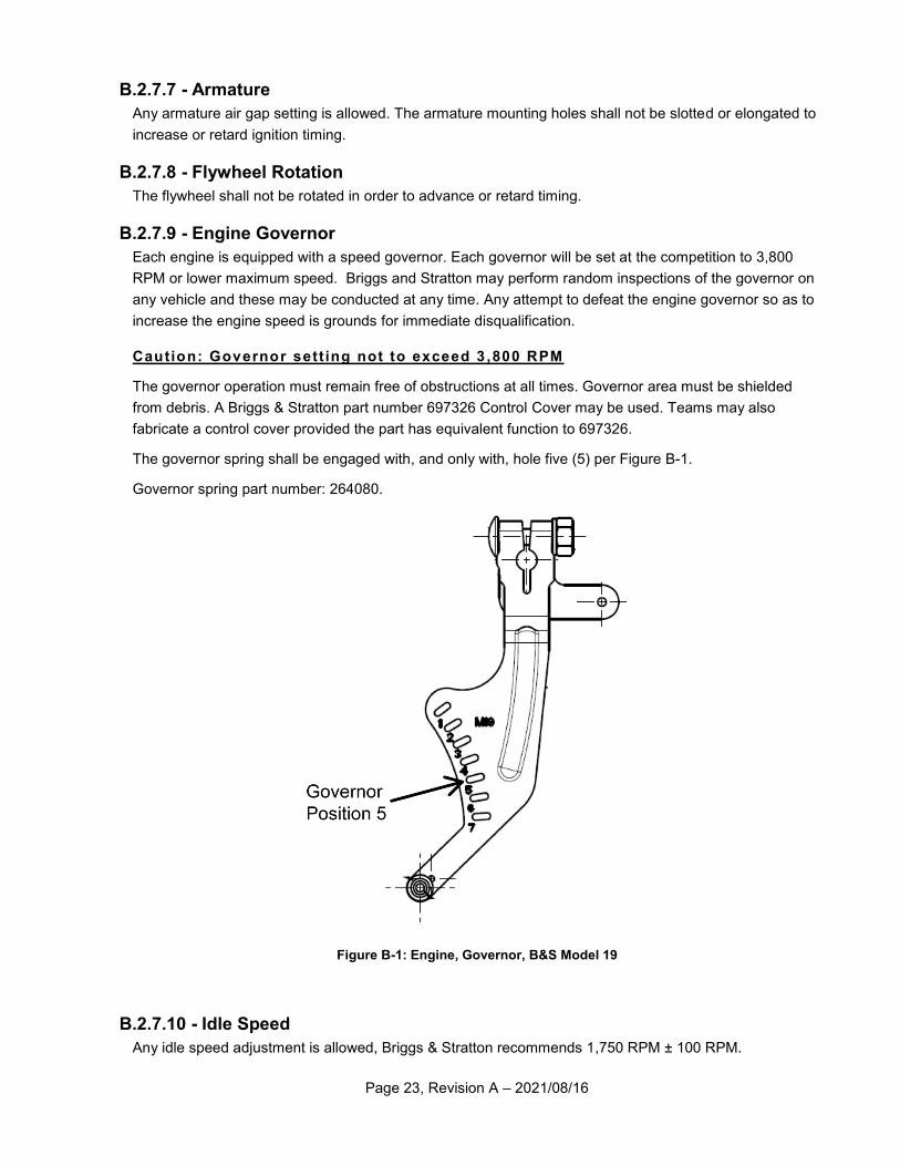
B.2.7.9 - Engine Governor
Each engine is equipped with a speed governor. Each governor will be set at the competition to 3,800
RPM or lower maximum speed. Briggs and Stratton may perform random inspections of the governor on
any vehicle and these may be conducted at any time. Any attempt to defeat the engine governor so as to
increase the engine speed is grounds for immediate disqualification.
Caution: Governor sett ing not to exceed 3 ,800 RPM
The governor operation must remain free of obstructions at all times. Governor area must be shielded
from debris. A Briggs & Stratton part number 697326 Control Cover may be used. Teams may also
fabricate a control cover provided the part has equivalent function to 697326.
The governor spring shall be engaged with, and only with, hole five (5) per Figure B-1.
Governor spring part number: 264080.
Figure B-1: Engine, Governor, B&S Model 19
B.2.7.10 - Idle Speed
Any idle speed adjustment is allowed, Briggs & Stratton recommends 1,750 RPM ± 100 RPM.
Page 24, Revision A – 2021/08/16
B.2.7.11 - Air Cleaner
The air intake cleaner may be relocated, but Briggs & Stratton parts must be used to relocate the air filter.
Parts 592251 (remote kit), 695329 (choke shaft), and 699960 (base) are permitted. No previous part
versions are allowed. The supplied intake air hose may be shortened to a minimum of 152 mm (6.0 in.).
No other type of hose will be allowed. A team may also add additional pre-filters to the top of the air
intake. These parts must be included on the cost report. Any changes made to the air filter will have to
pass inspection by Briggs & Stratton.
Note: Relocat ion of a ir f i l ter or c leaner hous ing may decrease engine performance.
B.2.7.12 - Carburetor
B.2.7.12.1 - Jetting
Modifying the carburetor jet or re-jetting of the carburetor is prohibited.
B.2.7.12.2 - Float
The carburetor float is not adjustable and may not be modified.
B.2.7.12.3 - Venturi
Modification of the carburetor venturi is prohibited.
B.2.7.13 - Exhaust System
B.2.7.13.1 - Muffler Relocation
If the vehicle design requires an exhaust system reconfiguration to keep it from impinging on part of the
vehicle, the re-routing must be done using tubing having an ID of 32 mm (1.25 in.). Any remote mounted
exhaust system must use the original muffler and must be securely mounted so that it does not vibrate
loose during the competition.
B.2.7.13.2 - Muffler Support
Supports for the exhaust pipe and muffler are required. Supports must be attached exclusively to the
engine.
B.2.7.13.3 - Exhaust Pipe Port
Exhaust pipe may not protrude inside of the exhaust port, so as to alter port configuration.
B.2.7.13.4 - Exhaust Pipe Length
Any exhaust pipe length is allowed, however pipe length may not be adjustable.
B.2.7.13.5 - Exhaust Pipe Continuity
No extra holes or tubes are allowed in the exhaust pipe. One inlet and one outlet are required.
B.2.7.13.6 - Exhaust Durability
The exhaust pipe and muffler must be durable, resilient, completely intact and functional throughout the
competition. Any vehicle found to have a loose or leaking exhaust system will be removed from
competition until the issue can be corrected.
Page 25, Revision A – 2021/08/16
B.2.7.13.7 - Muffler Cage
Teams are required to retain the OEM protective wire cage surrounding the muffler to reduce risk of
burns.
B.2.7.14 - Starting Devices
The starter pull rope may be extended to accommodate the driver starting the engine while seated.
Starter motors are explicitly prohibited.
B.2.7.15 - Alternator
The engine may be fitted with an approved alternator to generate electrical power. The only alternators
which are permitted are those which Briggs & Stratton specifies for the engine model. Available
alternators are sized in 3, 10, and 20 Ampere versions.
Article 3 - Roll Cage
B.3.1 - Objective
The purpose of the roll cage is to maintain a minimum space surrounding the driver. The cage must be
designed and fabricated to prevent any failure of the cage’s integrity during normal operation or during a
collision or roll over.
B.3.2 - Roll Cage Structure
The roll cage must be a space frame of tubular steel. The following section outlines the requirements of
the physical members and joining methods of the roll cage. Roll cage and Frame Members must be fully
welded, and welds must not be ground, sanded or modified so as to prevent inspection. Roll Cage
Members that are bent must not exhibit any wrinkles, kinks or any detrimental deformation to the cross-
section. Terminology used in the rule book relating to the roll cage structure is given below:
Frame: The entire tubular structure including all non-cantilevered tubes.
Roll Cage: Primary and Secondary Members used to protect the driver.
Member: A Primary or Secondary required element beginning and ending at Named Points.
Named Point: The intersection of the centerlines of two or more joining members.
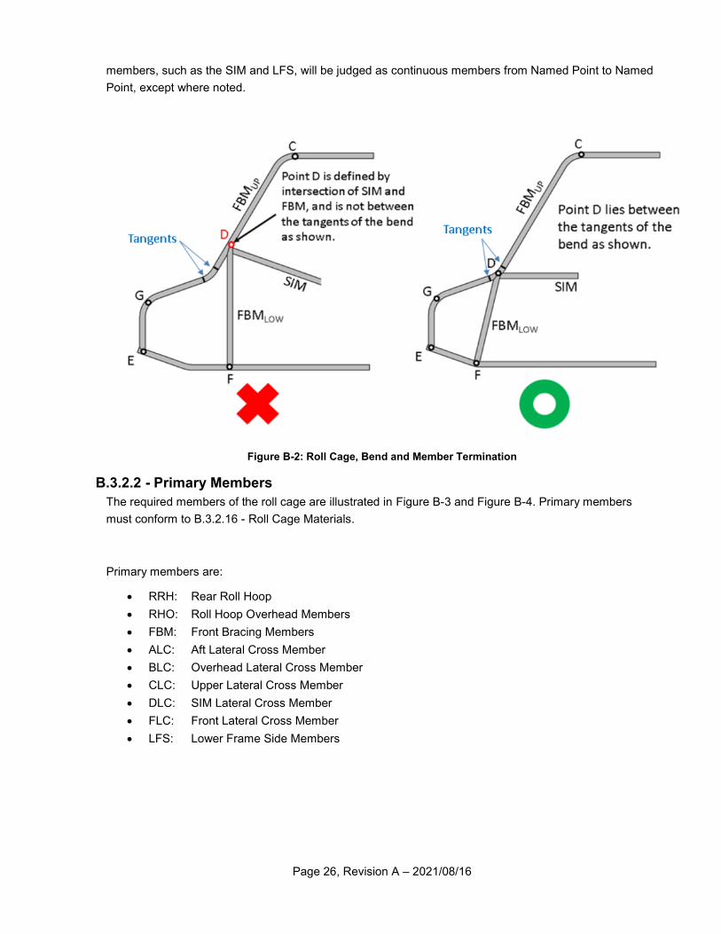
B.3.2.1 - Member Requirements
Roll cage members must be made of steel tube and may be straight or bent. Straight members may not
extend longer than 1016 mm (40 in.) between Named Points or comply with Rule B.3.2.4 - Additional
Support Members. Bent members may not have a bend greater than 30 deg. that does not occur at a
Named Point; and may not extend longer than 838 mm (33 in.) between Named Points or comply with
Rule B.3.2.4 - Additional Support Members. Small bend radii (<152 mm or 6 in.) that terminate at Named
Points are expected, and are not considered to make a member bent, regardless of angle. A bend that
terminates at a Named Point implies the point lies at or between the points of tangency of the bend, as
shown in Figure B-2. Required dimensions between roll cage members are defined by measurements
between member centerlines, except where noted. Junctions of Primary and Secondary members
described below must be within 51 mm (2.0 in) of the Named Point, except where noted.
Mitered tubing joints of greater than 5 deg. will be treated as bends. Miters of less than 5 deg. will be
treated as butt joints and subject to Rule B.3.2.14 - Butt Joints. Required members constructed of multiple
Page 26, Revision A – 2021/08/16
members, such as the SIM and LFS, will be judged as continuous members from Named Point to Named
Point, except where noted.
Figure B-2: Roll Cage, Bend and Member Termination
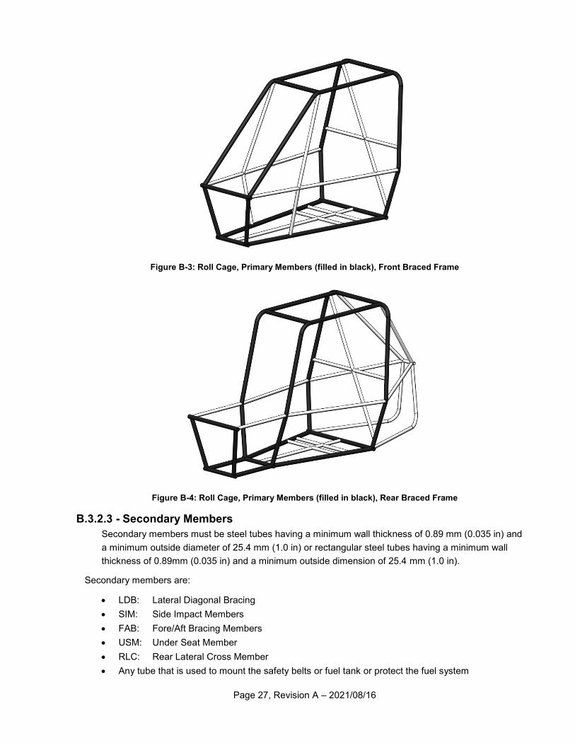
B.3.2.2 - Primary Members
The required members of the roll cage are illustrated in Figure B-3 and Figure B-4. Primary members
must conform to B.3.2.16 - Roll Cage Materials.
Primary members are:
RRH: Rear Roll Hoop
RHO: Roll Hoop Overhead Members
FBM: Front Bracing Members
ALC: Aft Lateral Cross Member
BLC: Overhead Lateral Cross Member
CLC: Upper Lateral Cross Member
DLC: SIM Lateral Cross Member
FLC: Front Lateral Cross Member
LFS: Lower Frame Side Members
Page 27, Revision A – 2021/08/16
Figure B-3: Roll Cage, Primary Members (filled in black), Front Braced Frame
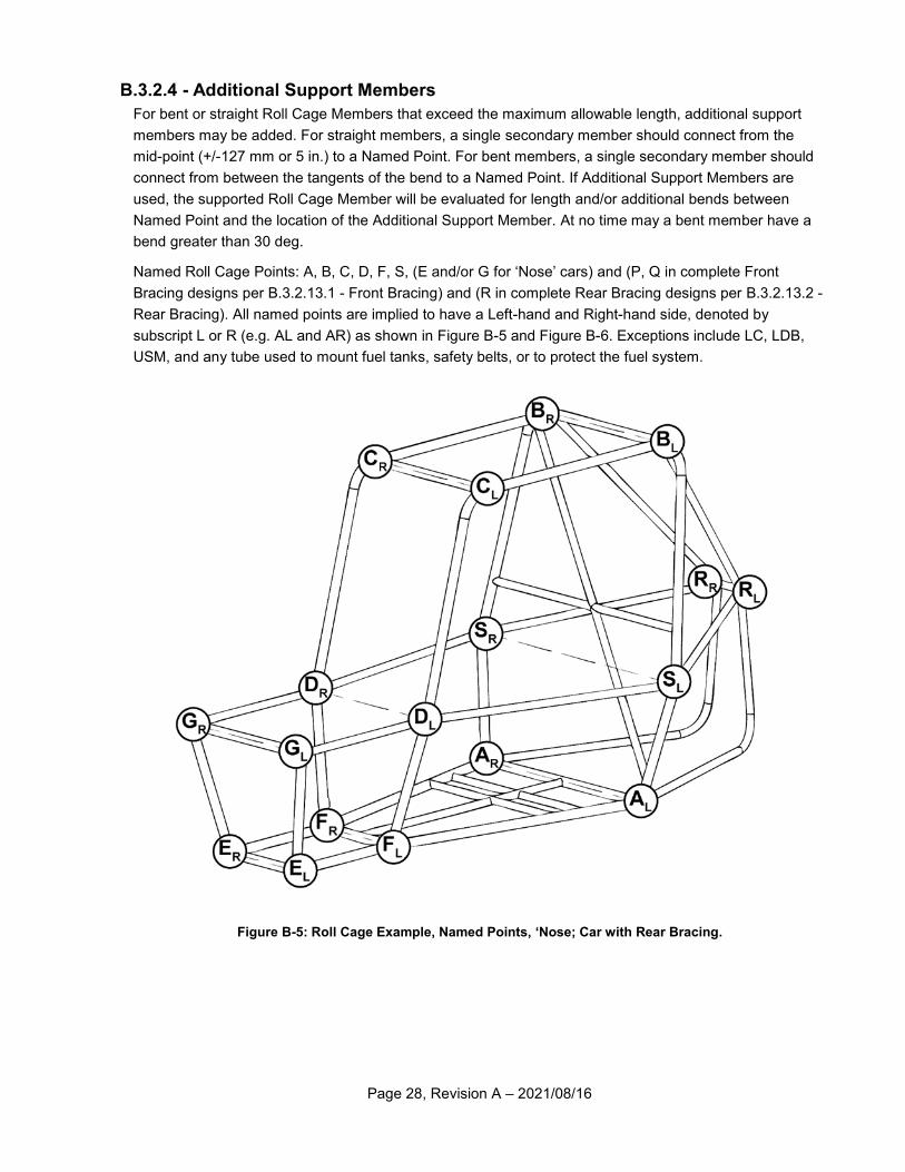
Figure B-4: Roll Cage, Primary Members (filled in black), Rear Braced Frame
B.3.2.3 - Secondary Members
Secondary members must be steel tubes having a minimum wall thickness of 0.89 mm (0.035 in) and
a minimum outside diameter of 25.4 mm (1.0 in) or rectangular steel tubes having a minimum wall
thickness of 0.89mm (0.035 in) and a minimum outside dimension of 25.4 mm (1.0 in).
Secondary members are:
LDB: Lateral Diagonal Bracing
SIM: Side Impact Members
FAB: Fore/Aft Bracing Members
USM: Under Seat Member
RLC: Rear Lateral Cross Member
Any tube that is used to mount the safety belts or fuel tank or protect the fuel system
Page 28, Revision A – 2021/08/16
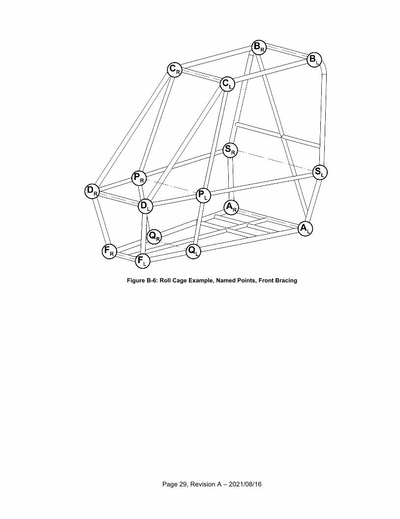
B.3.2.4 - Additional Support Members
For bent or straight Roll Cage Members that exceed the maximum allowable length, additional support
members may be added. For straight members, a single secondary member should connect from the
mid-point (+/-127 mm or 5 in.) to a Named Point. For bent members, a single secondary member should
connect from between the tangents of the bend to a Named Point. If Additional Support Members are
used, the supported Roll Cage Member will be evaluated for length and/or additional bends between
Named Point and the location of the Additional Support Member. At no time may a bent member have a
bend greater than 30 deg.
Named Roll Cage Points: A, B, C, D, F, S, (E and/or G for ‘Nose’ cars) and (P, Q in complete Front
Bracing designs per B.3.2.13.1 - Front Bracing) and (R in complete Rear Bracing designs per B.3.2.13.2 -
Rear Bracing). All named points are implied to have a Left-hand and Right-hand side, denoted by
subscript L or R (e.g. AL and AR) as shown in Figure B-5 and Figure B-6. Exceptions include LC, LDB,
USM, and any tube used to mount fuel tanks, safety belts, or to protect the fuel system.
Figure B-5: Roll Cage Example, Named Points, ‘Nose; Car with Rear Bracing.
Page 29, Revision A – 2021/08/16
Figure B-6: Roll Cage Example, Named Points, Front Bracing
Page 30, Revision A – 2021/08/16
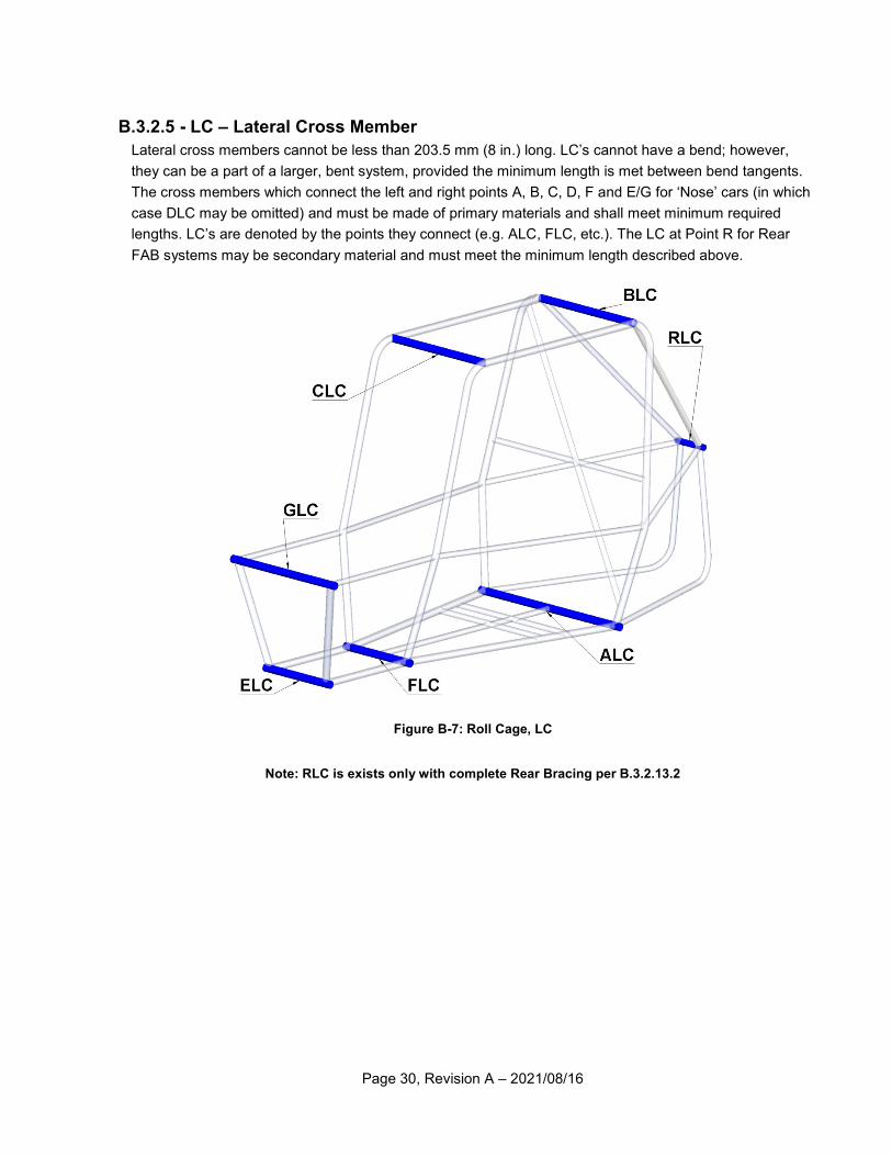
B.3.2.5 - LC – Lateral Cross Member
Lateral cross members cannot be less than 203.5 mm (8 in.) long. LC’s cannot have a bend; however,
they can be a part of a larger, bent system, provided the minimum length is met between bend tangents.
The cross members which connect the left and right points A, B, C, D, F and E/G for ‘Nose’ cars (in which
case DLC may be omitted) and must be made of primary materials and shall meet minimum required
lengths. LC’s are denoted by the points they connect (e.g. ALC, FLC, etc.). The LC at Point R for Rear
FAB systems may be secondary material and must meet the minimum length described above.
Figure B-7: Roll Cage, LC
Note: RLC is exists only with complete Rear Bracing per B.3.2.13.2
Page 31, Revision A – 2021/08/16
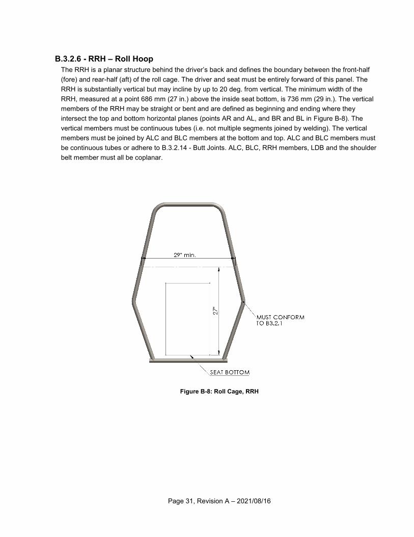
B.3.2.6 - RRH – Roll Hoop
The RRH is a planar structure behind the driver’s back and defines the boundary between the front-half
(fore) and rear-half (aft) of the roll cage. The driver and seat must be entirely forward of this panel. The
RRH is substantially vertical but may incline by up to 20 deg. from vertical. The minimum width of the
RRH, measured at a point 686 mm (27 in.) above the inside seat bottom, is 736 mm (29 in.). The vertical
members of the RRH may be straight or bent and are defined as beginning and ending where they
intersect the top and bottom horizontal planes (points AR and AL, and BR and BL in Figure B-8). The
vertical members must be continuous tubes (i.e. not multiple segments joined by welding). The vertical
members must be joined by ALC and BLC members at the bottom and top. ALC and BLC members must
be continuous tubes or adhere to B.3.2.14 - Butt Joints. ALC, BLC, RRH members, LDB and the shoulder
belt member must all be coplanar.
Figure B-8: Roll Cage, RRH
Page 32, Revision A – 2021/08/16
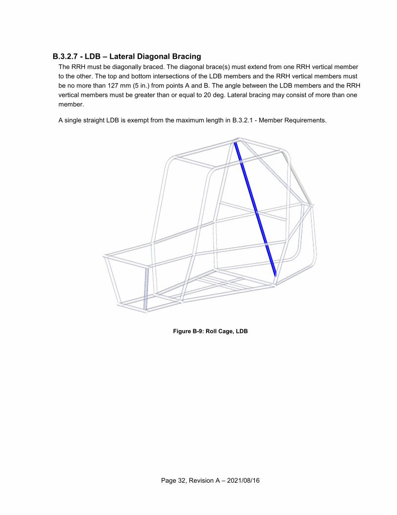
B.3.2.7 - LDB – Lateral Diagonal Bracing
The RRH must be diagonally braced. The diagonal brace(s) must extend from one RRH vertical member
to the other. The top and bottom intersections of the LDB members and the RRH vertical members must
be no more than 127 mm (5 in.) from points A and B. The angle between the LDB members and the RRH
vertical members must be greater than or equal to 20 deg. Lateral bracing may consist of more than one
member.
A single straight LDB is exempt from the maximum length in B.3.2.1 - Member Requirements.
Figure B-9: Roll Cage, LDB
Page 33, Revision A – 2021/08/16
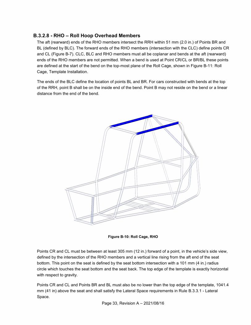
B.3.2.8 - RHO – Roll Hoop Overhead Members
The aft (rearward) ends of the RHO members intersect the RRH within 51 mm (2.0 in.) of Points BR and
BL (defined by BLC). The forward ends of the RHO members (intersection with the CLC) define points CR
and CL (Figure B-7). CLC, BLC and RHO members must all be coplanar and bends at the aft (rearward)
ends of the RHO members are not permitted. When a bend is used at Point CR/CL or BR/BL these points
are defined at the start of the bend on the top-most plane of the Roll Cage, shown in Figure B-11: Roll
Cage, Template Installation.
The ends of the BLC define the location of points BL and BR. For cars constructed with bends at the top
of the RRH, point B shall be on the inside end of the bend. Point B may not reside on the bend or a linear
distance from the end of the bend.
Figure B-10: Roll Cage, RHO
Points CR and CL must be between at least 305 mm (12 in.) forward of a point, in the vehicle’s side view,
defined by the intersection of the RHO members and a vertical line rising from the aft end of the seat
bottom. This point on the seat is defined by the seat bottom intersection with a 101 mm (4 in.) radius
circle which touches the seat bottom and the seat back. The top edge of the template is exactly horizontal
with respect to gravity.
Points CR and CL and Points BR and BL must also be no lower than the top edge of the template, 1041.4
mm (41 in) above the seat and shall satisfy the Lateral Space requirements in Rule B.3.3.1 - Lateral
Space.
Page 34, Revision A – 2021/08/16
Note: The top , longi tudinal edge of the template shal l be or iented exact ly hor izonta l
wi th respect to gravi ty.
Figure B-11: Roll Cage, Template Installation
Figure B-12: Roll Cage Template Drawing
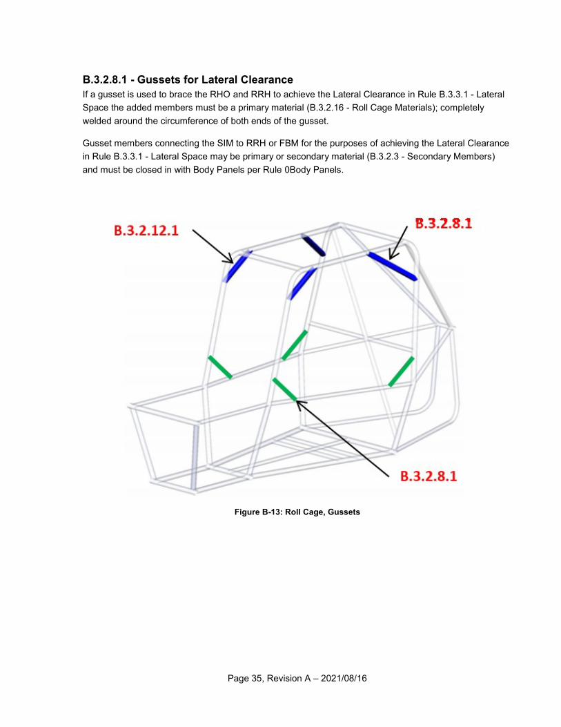
Page 35, Revision A – 2021/08/16
B.3.2.8.1 - Gussets for Lateral Clearance
If a gusset is used to brace the RHO and RRH to achieve the Lateral Clearance in Rule B.3.3.1 - Lateral
Space the added members must be a primary material (B.3.2.16 - Roll Cage Materials); completely
welded around the circumference of both ends of the gusset.
Gusset members connecting the SIM to RRH or FBM for the purposes of achieving the Lateral Clearance
in Rule B.3.3.1 - Lateral Space may be primary or secondary material (B.3.2.3 - Secondary Members)
and must be closed in with Body Panels per Rule 0Body Panels.
Figure B-13: Roll Cage, Gussets
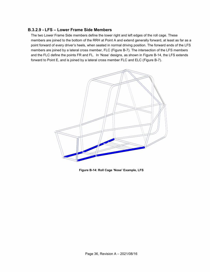
Page 36, Revision A – 2021/08/16
B.3.2.9 - LFS – Lower Frame Side Members
The two Lower Frame Side members define the lower right and left edges of the roll cage. These
members are joined to the bottom of the RRH at Point A and extend generally forward, at least as far as a
point forward of every driver’s heels, when seated in normal driving position. The forward ends of the LFS
members are joined by a lateral cross member, FLC (Figure B-7). The intersection of the LFS members
and the FLC define the points FR and FL. In ‘Nose’ designs, as shown in Figure B-14, the LFS extends
forward to Point E, and is joined by a lateral cross member FLC and ELC (Figure B-7).
Figure B-14: Roll Cage ‘Nose’ Example, LFS
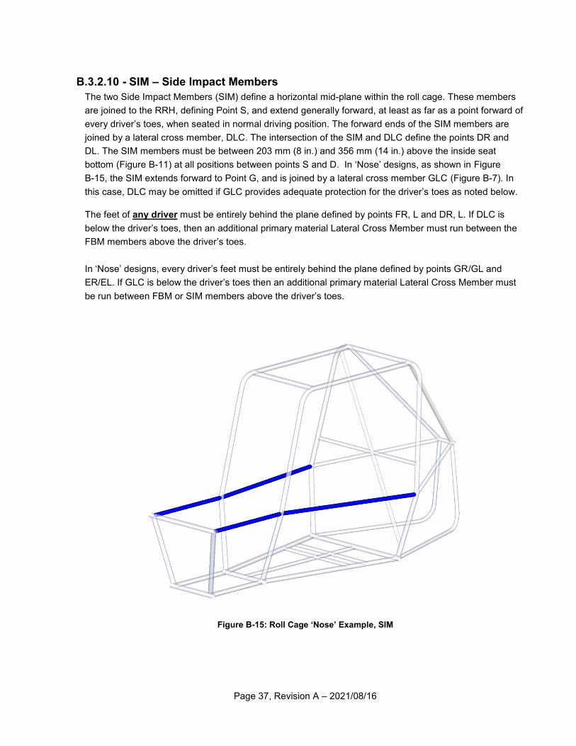
Page 37, Revision A – 2021/08/16
B.3.2.10 - SIM – Side Impact Members
The two Side Impact Members (SIM) define a horizontal mid-plane within the roll cage. These members
are joined to the RRH, defining Point S, and extend generally forward, at least as far as a point forward of
every driver’s toes, when seated in normal driving position. The forward ends of the SIM members are
joined by a lateral cross member, DLC. The intersection of the SIM and DLC define the points DR and
DL. The SIM members must be between 203 mm (8 in.) and 356 mm (14 in.) above the inside seat
bottom (Figure B-11) at all positions between points S and D. In ‘Nose’ designs, as shown in Figure
B-15, the SIM extends forward to Point G, and is joined by a lateral cross member GLC (Figure B-7). In
this case, DLC may be omitted if GLC provides adequate protection for the driver’s toes as noted below.
The feet of any driver must be entirely behind the plane defined by points FR, L and DR, L. If DLC is
below the driver’s toes, then an additional primary material Lateral Cross Member must run between the
FBM members above the driver’s toes.
In ‘Nose’ designs, every driver’s feet must be entirely behind the plane defined by points GR/GL and
ER/EL. If GLC is below the driver’s toes then an additional primary material Lateral Cross Member must
be run between FBM or SIM members above the driver’s toes.
Figure B-15: Roll Cage ‘Nose’ Example, SIM
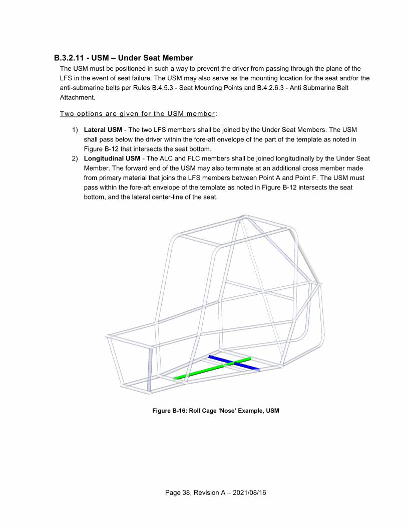
Page 38, Revision A – 2021/08/16
B.3.2.11 - USM – Under Seat Member
The USM must be positioned in such a way to prevent the driver from passing through the plane of the
LFS in the event of seat failure. The USM may also serve as the mounting location for the seat and/or the
anti-submarine belts per Rules B.4.5.3 - Seat Mounting Points and B.4.2.6.3 - Anti Submarine Belt
Attachment.
Two opt ions are g iven for the USM member :
1) Lateral USM - The two LFS members shall be joined by the Under Seat Members. The USM
shall pass below the driver within the fore-aft envelope of the part of the template as noted in
Figure B-12 that intersects the seat bottom.
2) Longitudinal USM - The ALC and FLC members shall be joined longitudinally by the Under Seat
Member. The forward end of the USM may also terminate at an additional cross member made
from primary material that joins the LFS members between Point A and Point F. The USM must
pass within the fore-aft envelope of the template as noted in Figure B-12 intersects the seat
bottom, and the lateral center-line of the seat.
Figure B-16: Roll Cage ‘Nose’ Example, USM
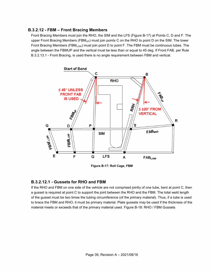
Page 39, Revision A – 2021/08/16
B.3.2.12 - FBM – Front Bracing Members
Front Bracing Members must join the RHO, the SIM and the LFS (Figure B-17) at Points C, D and F. The
upper Front Bracing Members (FBMUP) must join points C on the RHO to point D on the SIM. The lower
Front Bracing Members (FBMLOW) must join point D to point F. The FBM must be continuous tubes. The
angle between the FBMUP and the vertical must be less than or equal to 45 deg. If Front FAB, per Rule
B.3.2.13.1 - Front Bracing, is used there is no angle requirement between FBM and vertical.
Figure B-17: Roll Cage, FBM
B.3.2.12.1 - Gussets for RHO and FBM
If the RHO and FBM on one side of the vehicle are not comprised jointly of one tube, bent at point C, then
a gusset is required at point C to support the joint between the RHO and the FBM. The total weld length
of the gusset must be two times the tubing circumference (of the primary material). Thus, if a tube is used
to brace the FBM and RHO, it must be primary material. Plate gussets may be used if the thickness of the
material meets or exceeds that of the primary material used. Figure B-18: RHO / FBM Gussets
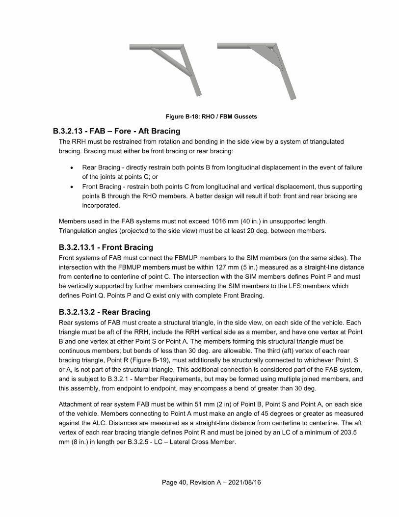
Page 40, Revision A – 2021/08/16
Figure B-18: RHO / FBM Gussets
B.3.2.13 - FAB – Fore - Aft Bracing
The RRH must be restrained from rotation and bending in the side view by a system of triangulated
bracing. Bracing must either be front bracing or rear bracing:
Rear Bracing - directly restrain both points B from longitudinal displacement in the event of failure
of the joints at points C; or
Front Bracing - restrain both points C from longitudinal and vertical displacement, thus supporting
points B through the RHO members. A better design will result if both front and rear bracing are
incorporated.
Members used in the FAB systems must not exceed 1016 mm (40 in.) in unsupported length.
Triangulation angles (projected to the side view) must be at least 20 deg. between members.
B.3.2.13.1 - Front Bracing
Front systems of FAB must connect the FBMUP members to the SIM members (on the same sides). The
intersection with the FBMUP members must be within 127 mm (5 in.) measured as a straight-line distance
from centerline to centerline of point C. The intersection with the SIM members defines Point P and must
be vertically supported by further members connecting the SIM members to the LFS members which
defines Point Q. Points P and Q exist only with complete Front Bracing.
B.3.2.13.2 - Rear Bracing
Rear systems of FAB must create a structural triangle, in the side view, on each side of the vehicle. Each
triangle must be aft of the RRH, include the RRH vertical side as a member, and have one vertex at Point
B and one vertex at either Point S or Point A. The members forming this structural triangle must be
continuous members; but bends of less than 30 deg. are allowable. The third (aft) vertex of each rear
bracing triangle, Point R (Figure B-19), must additionally be structurally connected to whichever Point, S
or A, is not part of the structural triangle. This additional connection is considered part of the FAB system,
and is subject to B.3.2.1 - Member Requirements, but may be formed using multiple joined members, and
this assembly, from endpoint to endpoint, may encompass a bend of greater than 30 deg.
Attachment of rear system FAB must be within 51 mm (2 in) of Point B, Point S and Point A, on each side
of the vehicle. Members connecting to Point A must make an angle of 45 degrees or greater as measured
against the ALC. Distances are measured as a straight-line distance from centerline to centerline. The aft
vertex of each rear bracing triangle defines Point R and must be joined by an LC of a minimum of 203.5
mm (8 in.) in length per B.3.2.5 - LC – Lateral Cross Member.
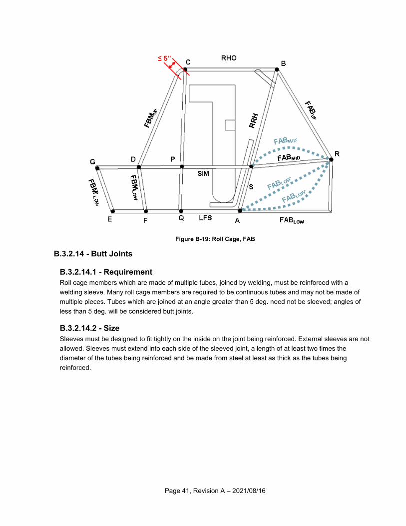
Page 41, Revision A – 2021/08/16
Figure B-19: Roll Cage, FAB
B.3.2.14 - Butt Joints
B.3.2.14.1 - Requirement
Roll cage members which are made of multiple tubes, joined by welding, must be reinforced with a
welding sleeve. Many roll cage members are required to be continuous tubes and may not be made of
multiple pieces. Tubes which are joined at an angle greater than 5 deg. need not be sleeved; angles of
less than 5 deg. will be considered butt joints.
B.3.2.14.2 - Size
Sleeves must be designed to fit tightly on the inside on the joint being reinforced. External sleeves are not
allowed. Sleeves must extend into each side of the sleeved joint, a length of at least two times the
diameter of the tubes being reinforced and be made from steel at least as thick as the tubes being
reinforced.
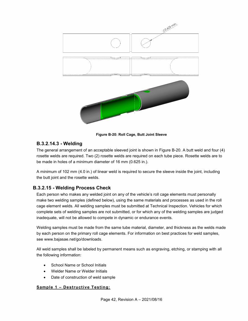
Page 42, Revision A – 2021/08/16
Figure B-20: Roll Cage, Butt Joint Sleeve
B.3.2.14.3 - Welding
The general arrangement of an acceptable sleeved joint is shown in Figure B-20. A butt weld and four (4)
rosette welds are required. Two (2) rosette welds are required on each tube piece. Rosette welds are to
be made in holes of a minimum diameter of 16 mm (0.625 in.).
A minimum of 102 mm (4.0 in.) of linear weld is required to secure the sleeve inside the joint, including
the butt joint and the rosette welds.
B.3.2.15 - Welding Process Check
Each person who makes any welded joint on any of the vehicle’s roll cage elements must personally
make two welding samples (defined below), using the same materials and processes as used in the roll
cage element welds. All welding samples must be submitted at Technical Inspection. Vehicles for which
complete sets of welding samples are not submitted, or for which any of the welding samples are judged
inadequate, will not be allowed to compete in dynamic or endurance events.
Welding samples must be made from the same tube material, diameter, and thickness as the welds made
by each person on the primary roll cage elements. For information on best practices for weld samples,
see www.bajasae.net/go/downloads.
All weld samples shall be labeled by permanent means such as engraving, etching, or stamping with all
the following information:
School Name or School Initials
Welder Name or Welder Initials
Date of construction of weld sample
Sample 1 – Destruct ive Testing:
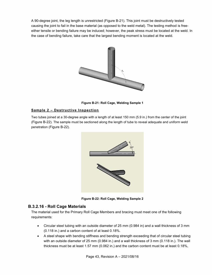
Page 43, Revision A – 2021/08/16
A 90-degree joint, the leg length is unrestricted (Figure B-21). This joint must be destructively tested
causing the joint to fail in the base material (as opposed to the weld metal). The testing method is free-
either tensile or bending failure may be induced; however, the peak stress must be located at the weld. In
the case of bending failure, take care that the largest bending moment is located at the weld.
Figure B-21: Roll Cage, Welding Sample 1
Sample 2 – Destruct ive Inspection
Two tubes joined at a 30-degree angle with a length of at least 150 mm (5.9 in.) from the center of the joint
(Figure B-22). The sample must be sectioned along the length of tube to reveal adequate and uniform weld
penetration (Figure B-22).
Figure B-22: Roll Cage, Welding Sample 2
B.3.2.16 - Roll Cage Materials
The material used for the Primary Roll Cage Members and bracing must meet one of the following
requirements:
Circular steel tubing with an outside diameter of 25 mm (0.984 in) and a wall thickness of 3 mm
(0.118 in.) and a carbon content of at least 0.18%.
A steel shape with bending stiffness and bending strength exceeding that of circular steel tubing
with an outside diameter of 25 mm (0.984 in.) and a wall thickness of 3 mm (0.118 in.). The wall
thickness must be at least 1.57 mm (0.062 in.) and the carbon content must be at least 0.18%,
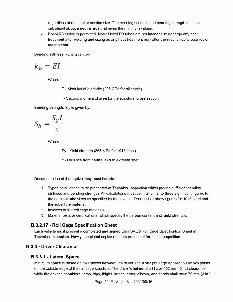
Page 44, Revision A – 2021/08/16
regardless of material or section size. The bending stiffness and bending strength must be
calculated about a neutral axis that gives the minimum values.
Docol R8 tubing is permitted. Note: Docol R8 tubes are not intended to undergo any heat
treatment after welding and sizing as any heat treatment may alter the mechanical properties of
the material.
Bending stiffness, kb, is given by:
Where:
E - Modulus of elasticity (205 GPa for all steels)
I - Second moment of area for the structural cross section
Bending strength, Sb, is given by:
Where:
Sy - Yield strength (365 MPa for 1018 steel)
c - Distance from neutral axis to extreme fiber
Documentation of the equivalency must include:
1) Typed calculations to be presented at Technical Inspection which proves sufficient bending
stiffness and bending strength. All calculations must be in SI units, to three significant figures to
the nominal tube sizes as specified by the invoice. Teams shall show figures for 1018 steel and
the substitute material.
2) Invoices of the roll cage materials.
3) Material tests or certifications, which specify the carbon content and yield strength.
B.3.2.17 - Roll Cage Specification Sheet
Each vehicle must present a completed and signed Baja SAE® Roll Cage Specification Sheet at
Technical Inspection. Newly completed copies must be presented for each competition.
B.3.3 - Driver Clearance
B.3.3.1 - Lateral Space
Minimum space is based on clearances between the driver and a straight edge applied to any two points
on the outside edge of the roll cage structure. The driver’s helmet shall have 152 mm (6 in.) clearance,
while the driver’s shoulders, torso, hips, thighs, knees, arms, elbows, and hands shall have 76 mm (3 in.)
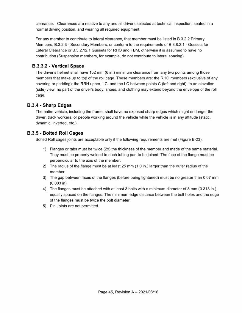
Page 45, Revision A – 2021/08/16
clearance. Clearances are relative to any and all drivers selected at technical inspection, seated in a
normal driving position, and wearing all required equipment.
For any member to contribute to lateral clearance, that member must be listed in B.3.2.2 Primary
Members, B.3.2.3 - Secondary Members, or conform to the requirements of B.3.8.2.1 - Gussets for
Lateral Clearance or B.3.2.12.1 Gussets for RHO and FBM, otherwise it is assumed to have no
contribution (Suspension members, for example, do not contribute to lateral spacing).
B.3.3.2 - Vertical Space
The driver’s helmet shall have 152 mm (6 in.) minimum clearance from any two points among those
members that make up to top of the roll cage. These members are: the RHO members (exclusive of any
covering or padding); the RRH upper, LC; and the LC between points C (left and right). In an elevation
(side) view, no part of the driver's body, shoes, and clothing may extend beyond the envelope of the roll
cage.
B.3.4 - Sharp Edges
The entire vehicle, including the frame, shall have no exposed sharp edges which might endanger the
driver, track workers, or people working around the vehicle while the vehicle is in any attitude (static,
dynamic, inverted, etc.).
B.3.5 - Bolted Roll Cages
Bolted Roll cages joints are acceptable only if the following requirements are met (Figure B-23):
1) Flanges or tabs must be twice (2x) the thickness of the member and made of the same material.
They must be properly welded to each tubing part to be joined. The face of the flange must be
perpendicular to the axis of the member.
2) The radius of the flange must be at least 25 mm (1.0 in.) larger than the outer radius of the
member.
3) The gap between faces of the flanges (before being tightened) must be no greater than 0.07 mm
(0.003 in).
4) The flanges must be attached with at least 3 bolts with a minimum diameter of 8 mm (0.313 in.),
equally spaced on the flanges. The minimum edge distance between the bolt holes and the edge
of the flanges must be twice the bolt diameter.
5) Pin Joints are not permitted.
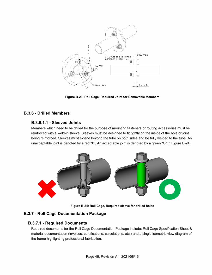
Page 46, Revision A – 2021/08/16
Figure B-23: Roll Cage, Required Joint for Removable Members
B.3.6 - Drilled Members
B.3.6.1.1 - Sleeved Joints
Members which need to be drilled for the purpose of mounting fasteners or routing accessories must be
reinforced with a weld-in sleeve. Sleeves must be designed to fit tightly on the inside of the hole or joint
being reinforced. Sleeves must extend beyond the tube on both sides and be fully welded to the tube. An
unacceptable joint is denoted by a red “X”. An acceptable joint is denoted by a green “O” in Figure B-24.
Figure B-24: Roll Cage, Required sleeve for drilled holes
B.3.7 - Roll Cage Documentation Package
B.3.7.1 - Required Documents
Required documents for the Roll Cage Documentation Package include: Roll Cage Specification Sheet &
material documentation (invoices, certifications, calculations, etc.) and a single isometric view diagram of
the frame highlighting professional fabrication.
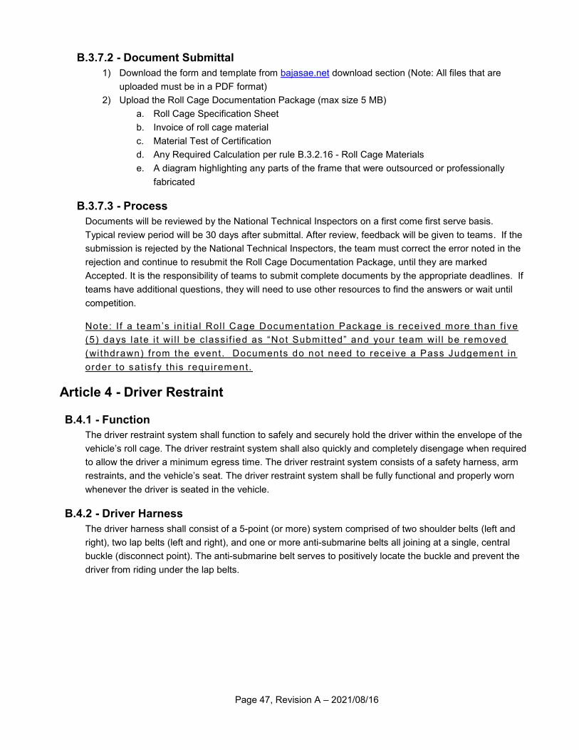
Page 47, Revision A – 2021/08/16
B.3.7.2 - Document Submittal
1) Download the form and template from bajasae.net download section (Note: All files that are
uploaded must be in a PDF format)
2) Upload the Roll Cage Documentation Package (max size 5 MB)
a. Roll Cage Specification Sheet
b. Invoice of roll cage material
c. Material Test of Certification
d. Any Required Calculation per rule B.3.2.16 - Roll Cage Materials
e. A diagram highlighting any parts of the frame that were outsourced or professionally
fabricated
B.3.7.3 - Process
Documents will be reviewed by the National Technical Inspectors on a first come first serve basis.
Typical review period will be 30 days after submittal. After review, feedback will be given to teams. If the
submission is rejected by the National Technical Inspectors, the team must correct the error noted in the
rejection and continue to resubmit the Roll Cage Documentation Package, until they are marked
Accepted. It is the responsibility of teams to submit complete documents by the appropriate deadlines. If
teams have additional questions, they will need to use other resources to find the answers or wait until
competition.
Note: I f a team’s in i t ia l Rol l Cage Documentat ion Package is received more than f ive
(5) days late i t wi l l be c lassif ied as “Not Submitted” and your team wi l l be removed
(wi thdrawn) f rom the event. Documents do not need to receive a Pass Judgement in
order to sat isf y this requirement.
Article 4 - Driver Restraint
B.4.1 - Function
The driver restraint system shall function to safely and securely hold the driver within the envelope of the
vehicle’s roll cage. The driver restraint system shall also quickly and completely disengage when required
to allow the driver a minimum egress time. The driver restraint system consists of a safety harness, arm
restraints, and the vehicle’s seat. The driver restraint system shall be fully functional and properly worn
whenever the driver is seated in the vehicle.
B.4.2 - Driver Harness
The driver harness shall consist of a 5-point (or more) system comprised of two shoulder belts (left and
right), two lap belts (left and right), and one or more anti-submarine belts all joining at a single, central
buckle (disconnect point). The anti-submarine belt serves to positively locate the buckle and prevent the
driver from riding under the lap belts.
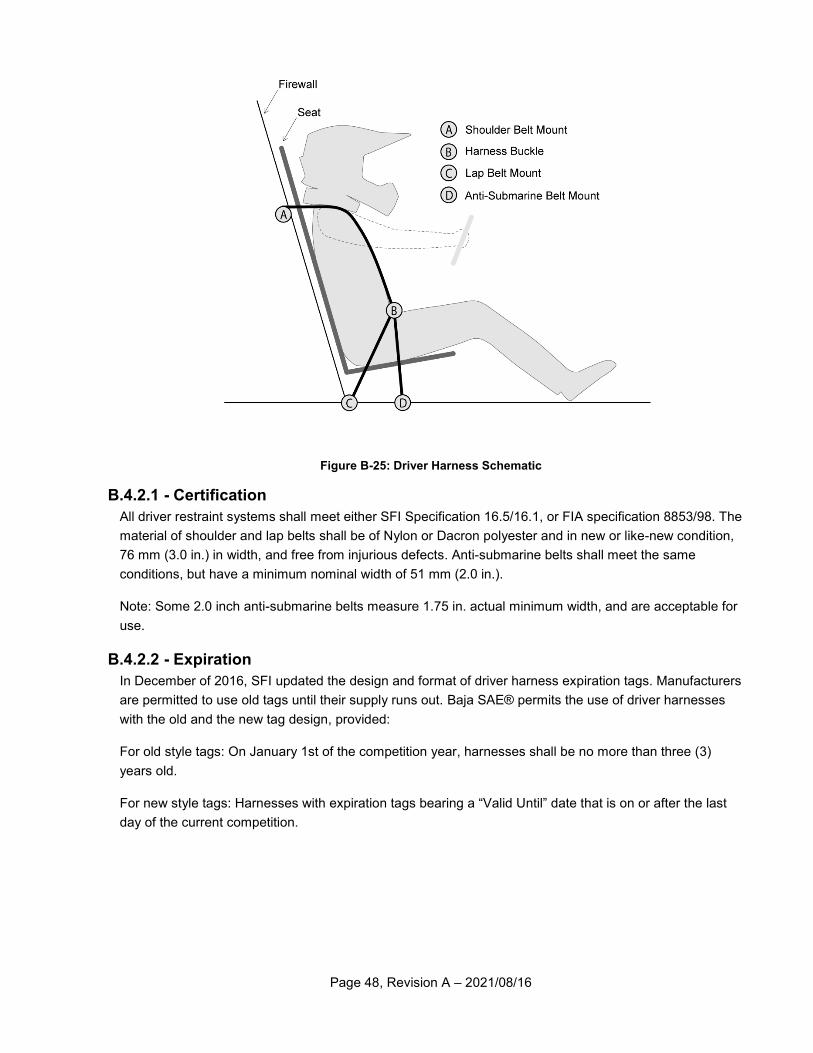
Page 48, Revision A – 2021/08/16
Figure B-25: Driver Harness Schematic
B.4.2.1 - Certification
All driver restraint systems shall meet either SFI Specification 16.5/16.1, or FIA specification 8853/98. The
material of shoulder and lap belts shall be of Nylon or Dacron polyester and in new or like-new condition,
76 mm (3.0 in.) in width, and free from injurious defects. Anti-submarine belts shall meet the same
conditions, but have a minimum nominal width of 51 mm (2.0 in.).
Note: Some 2.0 inch anti-submarine belts measure 1.75 in. actual minimum width, and are acceptable for
use.
B.4.2.2 - Expiration
In December of 2016, SFI updated the design and format of driver harness expiration tags. Manufacturers
are permitted to use old tags until their supply runs out. Baja SAE® permits the use of driver harnesses
with the old and the new tag design, provided:
For old style tags: On January 1st of the competition year, harnesses shall be no more than three (3)
years old.
For new style tags: Harnesses with expiration tags bearing a “Valid Until” date that is on or after the last
day of the current competition.
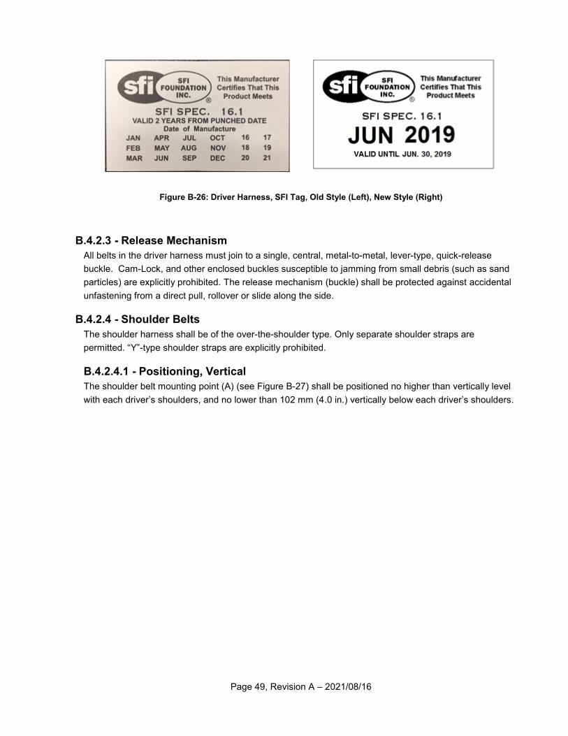
Page 49, Revision A – 2021/08/16
Figure B-26: Driver Harness, SFI Tag, Old Style (Left), New Style (Right)
B.4.2.3 - Release Mechanism
All belts in the driver harness must join to a single, central, metal-to-metal, lever-type, quick-release
buckle. Cam-Lock, and other enclosed buckles susceptible to jamming from small debris (such as sand
particles) are explicitly prohibited. The release mechanism (buckle) shall be protected against accidental
unfastening from a direct pull, rollover or slide along the side.
B.4.2.4 - Shoulder Belts
The shoulder harness shall be of the over-the-shoulder type. Only separate shoulder straps are
permitted. “Y”-type shoulder straps are explicitly prohibited.
B.4.2.4.1 - Positioning, Vertical
The shoulder belt mounting point (A) (see Figure B-27) shall be positioned no higher than vertically level
with each driver’s shoulders, and no lower than 102 mm (4.0 in.) vertically below each driver’s shoulders.
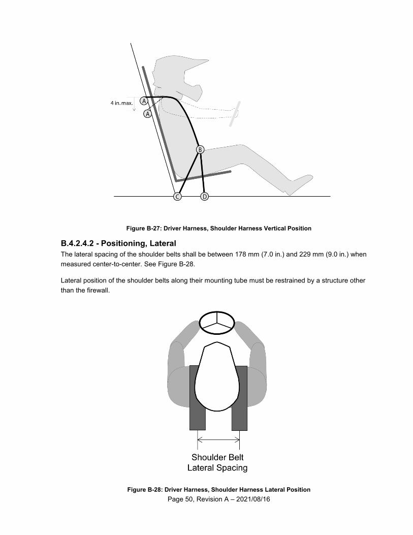
Page 50, Revision A – 2021/08/16
Figure B-27: Driver Harness, Shoulder Harness Vertical Position
B.4.2.4.2 - Positioning, Lateral
The lateral spacing of the shoulder belts shall be between 178 mm (7.0 in.) and 229 mm (9.0 in.) when
measured center-to-center. See Figure B-28.
Lateral position of the shoulder belts along their mounting tube must be restrained by a structure other
than the firewall.
Figure B-28: Driver Harness, Shoulder Harness Lateral Position
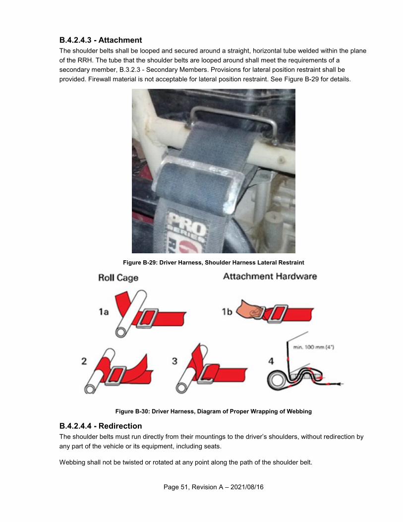
Page 51, Revision A – 2021/08/16
B.4.2.4.3 - Attachment
The shoulder belts shall be looped and secured around a straight, horizontal tube welded within the plane
of the RRH. The tube that the shoulder belts are looped around shall meet the requirements of a
secondary member, B.3.2.3 - Secondary Members. Provisions for lateral position restraint shall be
provided. Firewall material is not acceptable for lateral position restraint. See Figure B-29 for details.
Figure B-29: Driver Harness, Shoulder Harness Lateral Restraint
Figure B-30: Driver Harness, Diagram of Proper Wrapping of Webbing
B.4.2.4.4 - Redirection
The shoulder belts must run directly from their mountings to the driver’s shoulders, without redirection by
any part of the vehicle or its equipment, including seats.
Webbing shall not be twisted or rotated at any point along the path of the shoulder belt.
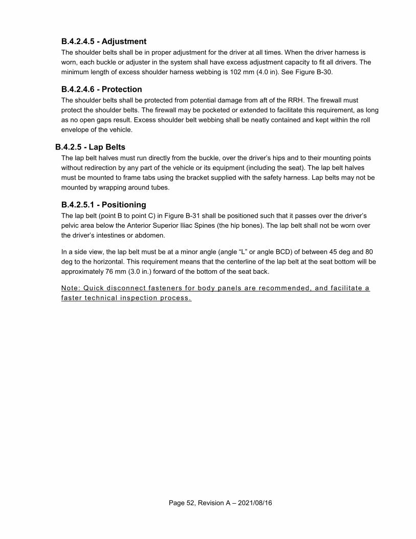
Page 52, Revision A – 2021/08/16
B.4.2.4.5 - Adjustment
The shoulder belts shall be in proper adjustment for the driver at all times. When the driver harness is
worn, each buckle or adjuster in the system shall have excess adjustment capacity to fit all drivers. The
minimum length of excess shoulder harness webbing is 102 mm (4.0 in). See Figure B-30.
B.4.2.4.6 - Protection
The shoulder belts shall be protected from potential damage from aft of the RRH. The firewall must
protect the shoulder belts. The firewall may be pocketed or extended to facilitate this requirement, as long
as no open gaps result. Excess shoulder belt webbing shall be neatly contained and kept within the roll
envelope of the vehicle.
B.4.2.5 - Lap Belts
The lap belt halves must run directly from the buckle, over the driver’s hips and to their mounting points
without redirection by any part of the vehicle or its equipment (including the seat). The lap belt halves
must be mounted to frame tabs using the bracket supplied with the safety harness. Lap belts may not be
mounted by wrapping around tubes.
B.4.2.5.1 - Positioning
The lap belt (point B to point C) in Figure B-31 shall be positioned such that it passes over the driver’s
pelvic area below the Anterior Superior Iliac Spines (the hip bones). The lap belt shall not be worn over
the driver’s intestines or abdomen.
In a side view, the lap belt must be at a minor angle (angle “L” or angle BCD) of between 45 deg and 80
deg to the horizontal. This requirement means that the centerline of the lap belt at the seat bottom will be
approximately 76 mm (3.0 in.) forward of the bottom of the seat back.
Note: Quick d isconnect fas teners for body panels are recommended, and fac i l i ta te a
faster technical inspect ion process.
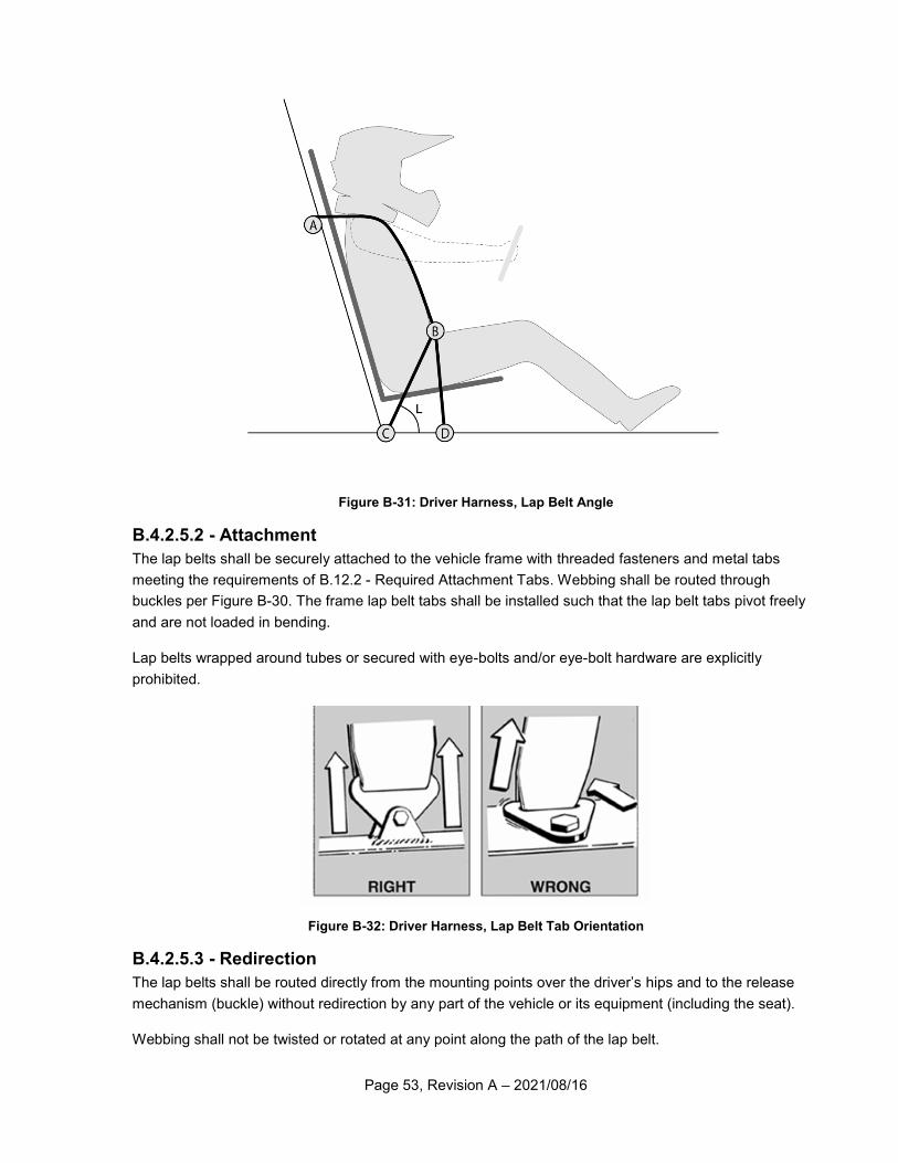
Page 53, Revision A – 2021/08/16
Figure B-31: Driver Harness, Lap Belt Angle
B.4.2.5.2 - Attachment
The lap belts shall be securely attached to the vehicle frame with threaded fasteners and metal tabs
meeting the requirements of B.12.2 - Required Attachment Tabs. Webbing shall be routed through
buckles per Figure B-30. The frame lap belt tabs shall be installed such that the lap belt tabs pivot freely
and are not loaded in bending.
Lap belts wrapped around tubes or secured with eye-bolts and/or eye-bolt hardware are explicitly
prohibited.
Figure B-32: Driver Harness, Lap Belt Tab Orientation
B.4.2.5.3 - Redirection
The lap belts shall be routed directly from the mounting points over the driver’s hips and to the release
mechanism (buckle) without redirection by any part of the vehicle or its equipment (including the seat).
Webbing shall not be twisted or rotated at any point along the path of the lap belt.
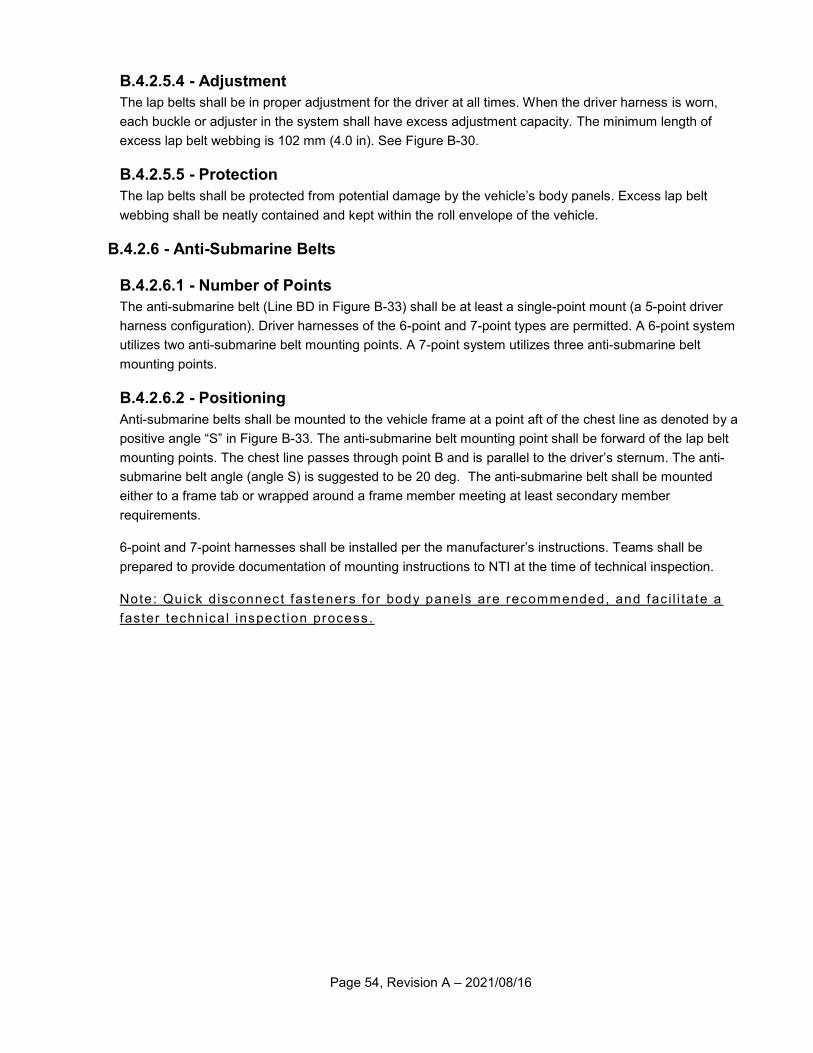
Page 54, Revision A – 2021/08/16
B.4.2.5.4 - Adjustment
The lap belts shall be in proper adjustment for the driver at all times. When the driver harness is worn,
each buckle or adjuster in the system shall have excess adjustment capacity. The minimum length of
excess lap belt webbing is 102 mm (4.0 in). See Figure B-30.
B.4.2.5.5 - Protection
The lap belts shall be protected from potential damage by the vehicle’s body panels. Excess lap belt
webbing shall be neatly contained and kept within the roll envelope of the vehicle.
B.4.2.6 - Anti-Submarine Belts
B.4.2.6.1 - Number of Points
The anti-submarine belt (Line BD in Figure B-33) shall be at least a single-point mount (a 5-point driver
harness configuration). Driver harnesses of the 6-point and 7-point types are permitted. A 6-point system
utilizes two anti-submarine belt mounting points. A 7-point system utilizes three anti-submarine belt
mounting points.
B.4.2.6.2 - Positioning
Anti-submarine belts shall be mounted to the vehicle frame at a point aft of the chest line as denoted by a
positive angle “S” in Figure B-33. The anti-submarine belt mounting point shall be forward of the lap belt
mounting points. The chest line passes through point B and is parallel to the driver’s sternum. The anti-
submarine belt angle (angle S) is suggested to be 20 deg. The anti-submarine belt shall be mounted
either to a frame tab or wrapped around a frame member meeting at least secondary member
requirements.
6-point and 7-point harnesses shall be installed per the manufacturer’s instructions. Teams shall be
prepared to provide documentation of mounting instructions to NTI at the time of technical inspection.
Note: Quick d isconnect fas teners for body panels are recommended, and fac i l i ta te a
faster technical inspect ion process.
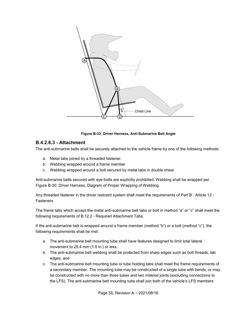
Page 55, Revision A – 2021/08/16
Figure B-33: Driver Harness, Anti-Submarine Belt Angle
B.4.2.6.3 - Attachment
The anti-submarine belts shall be securely attached to the vehicle frame by one of the following methods:
a. Metal tabs joined by a threaded fastener.
b. Webbing wrapped around a frame member
c. Webbing wrapped around a bolt secured by metal tabs in double shear.
Anti-submarine belts secured with eye-bolts are explicitly prohibited. Webbing shall be wrapped per
Figure B-30: Driver Harness, Diagram of Proper Wrapping of Webbing.
Any threaded fastener in the driver restraint system shall meet the requirements of Part B : Article 12 -
Fasteners
The frame tabs which accept the metal anti-submarine belt tabs or bolt in method “a” or “c” shall meet the
following requirements of B.12.2 - Required Attachment Tabs.
If the anti-submarine belt is wrapped around a frame member (method “b”) or a bolt (method “c”), the
following requirements shall be met:
a. The anti-submarine belt mounting tube shall have features designed to limit total lateral
movement to 25.4 mm (1.0 in.) or less.
b. The anti-submarine belt webbing shall be protected from sharp edges such as bolt threads, tab
edges, and
c. The anti-submarine belt mounting tube or tube holding tabs shall meet the frame requirements of
a secondary member. The mounting tube may be constructed of a single tube with bends, or may
be constructed with no more than three tubes and two mitered joints (excluding connections to
the LFS). The anti-submarine belt mounting tube shall join both of the vehicle’s LFS members
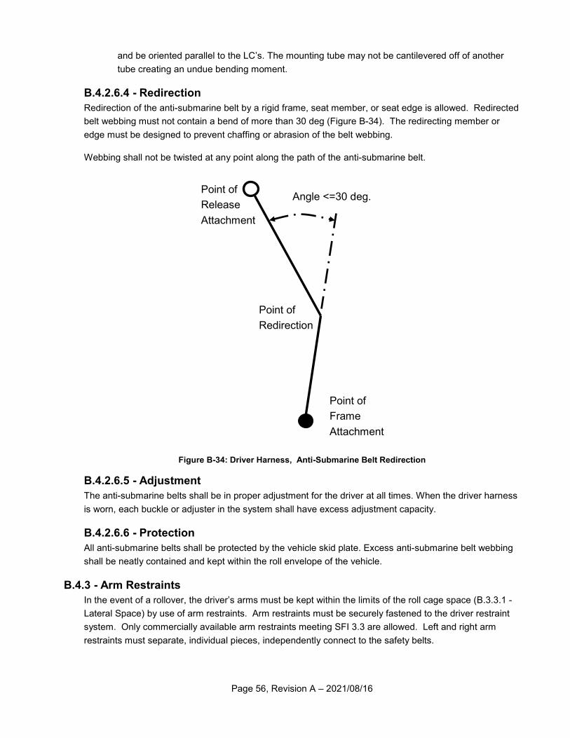
Page 56, Revision A – 2021/08/16
and be oriented parallel to the LC’s. The mounting tube may not be cantilevered off of another
tube creating an undue bending moment.
B.4.2.6.4 - Redirection
Redirection of the anti-submarine belt by a rigid frame, seat member, or seat edge is allowed. Redirected
belt webbing must not contain a bend of more than 30 deg (Figure B-34). The redirecting member or
edge must be designed to prevent chaffing or abrasion of the belt webbing.
Webbing shall not be twisted at any point along the path of the anti-submarine belt.
Figure B-34: Driver Harness, Anti-Submarine Belt Redirection
B.4.2.6.5 - Adjustment
The anti-submarine belts shall be in proper adjustment for the driver at all times. When the driver harness
is worn, each buckle or adjuster in the system shall have excess adjustment capacity.
B.4.2.6.6 - Protection
All anti-submarine belts shall be protected by the vehicle skid plate. Excess anti-submarine belt webbing
shall be neatly contained and kept within the roll envelope of the vehicle.
B.4.3 - Arm Restraints
In the event of a rollover, the driver’s arms must be kept within the limits of the roll cage space (B.3.3.1 -
Lateral Space) by use of arm restraints. Arm restraints must be securely fastened to the driver restraint
system. Only commercially available arm restraints meeting SFI 3.3 are allowed. Left and right arm
restraints must separate, individual pieces, independently connect to the safety belts.
Point of
Release
Attachment
Point of
Redirection
Point of
Frame
Attachment
Angle <=30 deg.
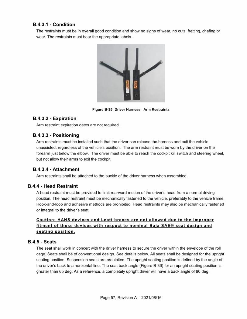
Page 57, Revision A – 2021/08/16
B.4.3.1 - Condition
The restraints must be in overall good condition and show no signs of wear, no cuts, fretting, chafing or
wear. The restraints must bear the appropriate labels.
Figure B-35: Driver Harness, Arm Restraints
B.4.3.2 - Expiration
Arm restraint expiration dates are not required.
B.4.3.3 - Positioning
Arm restraints must be installed such that the driver can release the harness and exit the vehicle
unassisted, regardless of the vehicle’s position. The arm restraint must be worn by the driver on the
forearm just below the elbow. The driver must be able to reach the cockpit kill switch and steering wheel,
but not allow their arms to exit the cockpit.
B.4.3.4 - Attachment
Arm restraints shall be attached to the buckle of the driver harness when assembled.
B.4.4 - Head Restraint
A head restraint must be provided to limit rearward motion of the driver’s head from a normal driving
position. The head restraint must be mechanically fastened to the vehicle, preferably to the vehicle frame.
Hook-and-loop and adhesive methods are prohibited. Head restraints may also be mechanically fastened
or integral to the driver’s seat.
Caution: HANS devices and Leatt braces are not al lowed due to the improper
f itment of these devices with respect to nominal Baja SAE® seat design and
seat ing posit ion.
B.4.5 - Seats
The seat shall work in concert with the driver harness to secure the driver within the envelope of the roll
cage. Seats shall be of conventional design. See details below. All seats shall be designed for the upright
seating position. Suspension seats are prohibited. The upright seating position is defined by the angle of
the driver’s back to a horizontal line. The seat back angle (Figure B-36) for an upright seating position is
greater than 65 deg. As a reference, a completely upright driver will have a back angle of 90 deg.
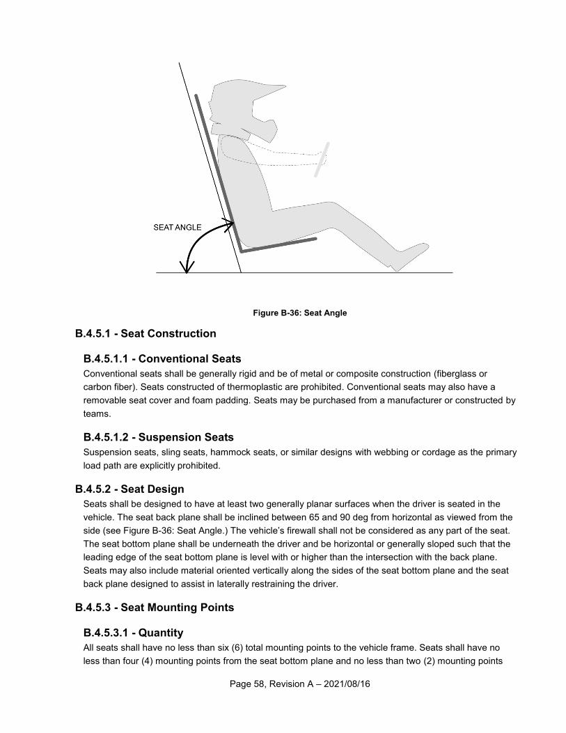
Page 58, Revision A – 2021/08/16
Figure B-36: Seat Angle
B.4.5.1 - Seat Construction
B.4.5.1.1 - Conventional Seats
Conventional seats shall be generally rigid and be of metal or composite construction (fiberglass or
carbon fiber). Seats constructed of thermoplastic are prohibited. Conventional seats may also have a
removable seat cover and foam padding. Seats may be purchased from a manufacturer or constructed by
teams.
B.4.5.1.2 - Suspension Seats
Suspension seats, sling seats, hammock seats, or similar designs with webbing or cordage as the primary
load path are explicitly prohibited.
B.4.5.2 - Seat Design
Seats shall be designed to have at least two generally planar surfaces when the driver is seated in the
vehicle. The seat back plane shall be inclined between 65 and 90 deg from horizontal as viewed from the
side (see Figure B-36: Seat Angle.) The vehicle’s firewall shall not be considered as any part of the seat.
The seat bottom plane shall be underneath the driver and be horizontal or generally sloped such that the
leading edge of the seat bottom plane is level with or higher than the intersection with the back plane.
Seats may also include material oriented vertically along the sides of the seat bottom plane and the seat
back plane designed to assist in laterally restraining the driver.
B.4.5.3 - Seat Mounting Points
B.4.5.3.1 - Quantity
All seats shall have no less than six (6) total mounting points to the vehicle frame. Seats shall have no
less than four (4) mounting points from the seat bottom plane and no less than two (2) mounting points
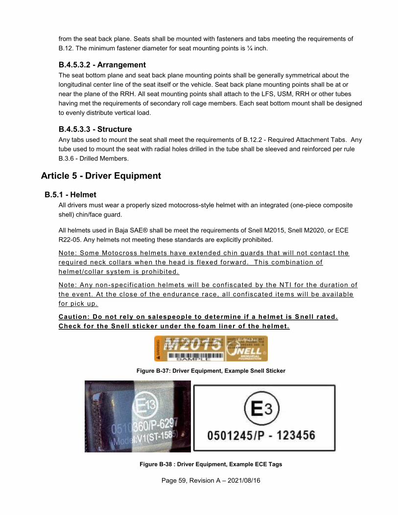
Page 59, Revision A – 2021/08/16
from the seat back plane. Seats shall be mounted with fasteners and tabs meeting the requirements of
B.12. The minimum fastener diameter for seat mounting points is ¼ inch.
B.4.5.3.2 - Arrangement
The seat bottom plane and seat back plane mounting points shall be generally symmetrical about the
longitudinal center line of the seat itself or the vehicle. Seat back plane mounting points shall be at or
near the plane of the RRH. All seat mounting points shall attach to the LFS, USM, RRH or other tubes
having met the requirements of secondary roll cage members. Each seat bottom mount shall be designed
to evenly distribute vertical load.
B.4.5.3.3 - Structure
Any tabs used to mount the seat shall meet the requirements of B.12.2 - Required Attachment Tabs. Any
tube used to mount the seat with radial holes drilled in the tube shall be sleeved and reinforced per rule
B.3.6 - Drilled Members.
Article 5 - Driver Equipment
B.5.1 - Helmet
All drivers must wear a properly sized motocross-style helmet with an integrated (one-piece composite
shell) chin/face guard.
All helmets used in Baja SAE® shall be meet the requirements of Snell M2015, Snell M2020, or ECE
R22-05. Any helmets not meeting these standards are explicitly prohibited.
Note: Some Motocross helmets have extended chin guards that wi l l not contact the
required neck col lars when the head is f lexed forward. This combinat ion of
helmet /col lar system is prohib i ted.
Note: Any non-spec if icat ion helmets wi l l be conf iscated by the NTI for the durat ion of
the event. At the c lose of the endurance race, a l l conf iscated i te ms wi l l be avai lable
for p ick up.
Caution: Do not rely on salespeople to determine if a helmet is S nell rated.
Check for the Snell st icker under the foam liner of the helmet.
Figure B-37: Driver Equipment, Example Snell Sticker
Figure B-38 : Driver Equipment, Example ECE Tags
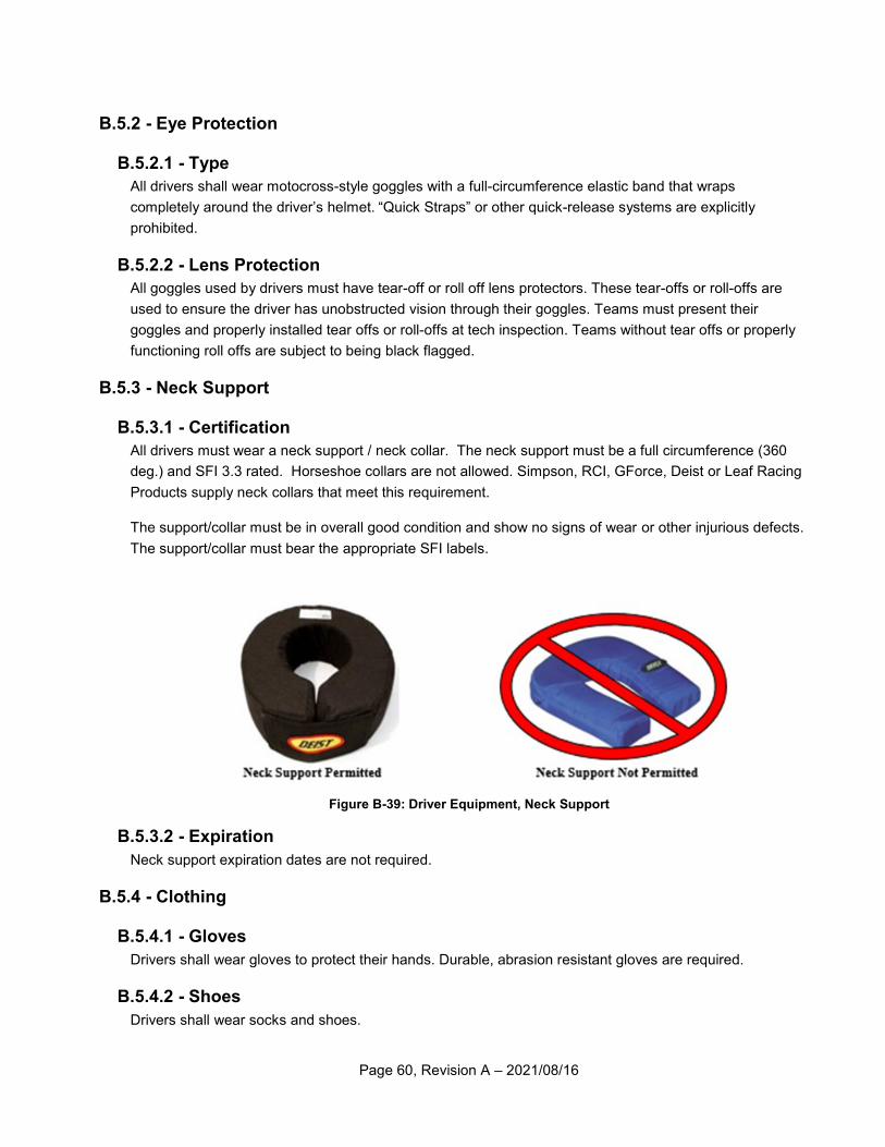
Page 60, Revision A – 2021/08/16
B.5.2 - Eye Protection
B.5.2.1 - Type
All drivers shall wear motocross-style goggles with a full-circumference elastic band that wraps
completely around the driver’s helmet. “Quick Straps” or other quick-release systems are explicitly
prohibited.
B.5.2.2 - Lens Protection
All goggles used by drivers must have tear-off or roll off lens protectors. These tear-offs or roll-offs are
used to ensure the driver has unobstructed vision through their goggles. Teams must present their
goggles and properly installed tear offs or roll-offs at tech inspection. Teams without tear offs or properly
functioning roll offs are subject to being black flagged.
B.5.3 - Neck Support
B.5.3.1 - Certification
All drivers must wear a neck support / neck collar. The neck support must be a full circumference (360
deg.) and SFI 3.3 rated. Horseshoe collars are not allowed. Simpson, RCI, GForce, Deist or Leaf Racing
Products supply neck collars that meet this requirement.
The support/collar must be in overall good condition and show no signs of wear or other injurious defects.
The support/collar must bear the appropriate SFI labels.
Figure B-39: Driver Equipment, Neck Support
B.5.3.2 - Expiration
Neck support expiration dates are not required.
B.5.4 - Clothing
B.5.4.1 - Gloves
Drivers shall wear gloves to protect their hands. Durable, abrasion resistant gloves are required.
B.5.4.2 - Shoes
Drivers shall wear socks and shoes.
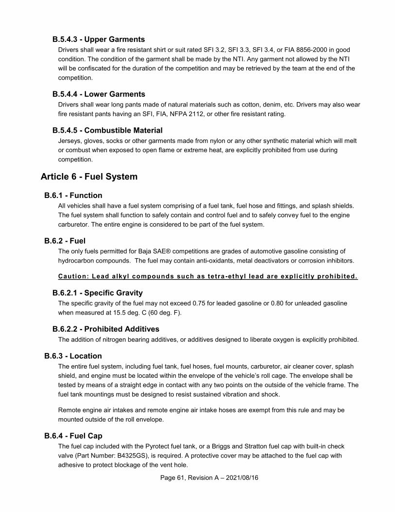
Page 61, Revision A – 2021/08/16
B.5.4.3 - Upper Garments
Drivers shall wear a fire resistant shirt or suit rated SFI 3.2, SFI 3.3, SFI 3.4, or FIA 8856-2000 in good
condition. The condition of the garment shall be made by the NTI. Any garment not allowed by the NTI
will be confiscated for the duration of the competition and may be retrieved by the team at the end of the
competition.
B.5.4.4 - Lower Garments
Drivers shall wear long pants made of natural materials such as cotton, denim, etc. Drivers may also wear
fire resistant pants having an SFI, FIA, NFPA 2112, or other fire resistant rating.
B.5.4.5 - Combustible Material
Jerseys, gloves, socks or other garments made from nylon or any other synthetic material which will melt
or combust when exposed to open flame or extreme heat, are explicitly prohibited from use during
competition.
Article 6 - Fuel System
B.6.1 - Function
All vehicles shall have a fuel system comprising of a fuel tank, fuel hose and fittings, and splash shields.
The fuel system shall function to safely contain and control fuel and to safely convey fuel to the engine
carburetor. The entire engine is considered to be part of the fuel system.
B.6.2 - Fuel
The only fuels permitted for Baja SAE® competitions are grades of automotive gasoline consisting of
hydrocarbon compounds. The fuel may contain anti-oxidants, metal deactivators or corrosion inhibitors.
Caution: Lead alkyl compounds such as tetra -ethyl lead are explicit ly prohibited.
B.6.2.1 - Specific Gravity
The specific gravity of the fuel may not exceed 0.75 for leaded gasoline or 0.80 for unleaded gasoline
when measured at 15.5 deg. C (60 deg. F).
B.6.2.2 - Prohibited Additives
The addition of nitrogen bearing additives, or additives designed to liberate oxygen is explicitly prohibited.
B.6.3 - Location
The entire fuel system, including fuel tank, fuel hoses, fuel mounts, carburetor, air cleaner cover, splash
shield, and engine must be located within the envelope of the vehicle’s roll cage. The envelope shall be
tested by means of a straight edge in contact with any two points on the outside of the vehicle frame. The
fuel tank mountings must be designed to resist sustained vibration and shock.
Remote engine air intakes and remote engine air intake hoses are exempt from this rule and may be
mounted outside of the roll envelope.
B.6.4 - Fuel Cap
The fuel cap included with the Pyrotect fuel tank, or a Briggs and Stratton fuel cap with built-in check
valve (Part Number: B4325GS), is required. A protective cover may be attached to the fuel cap with
adhesive to protect blockage of the vent hole.
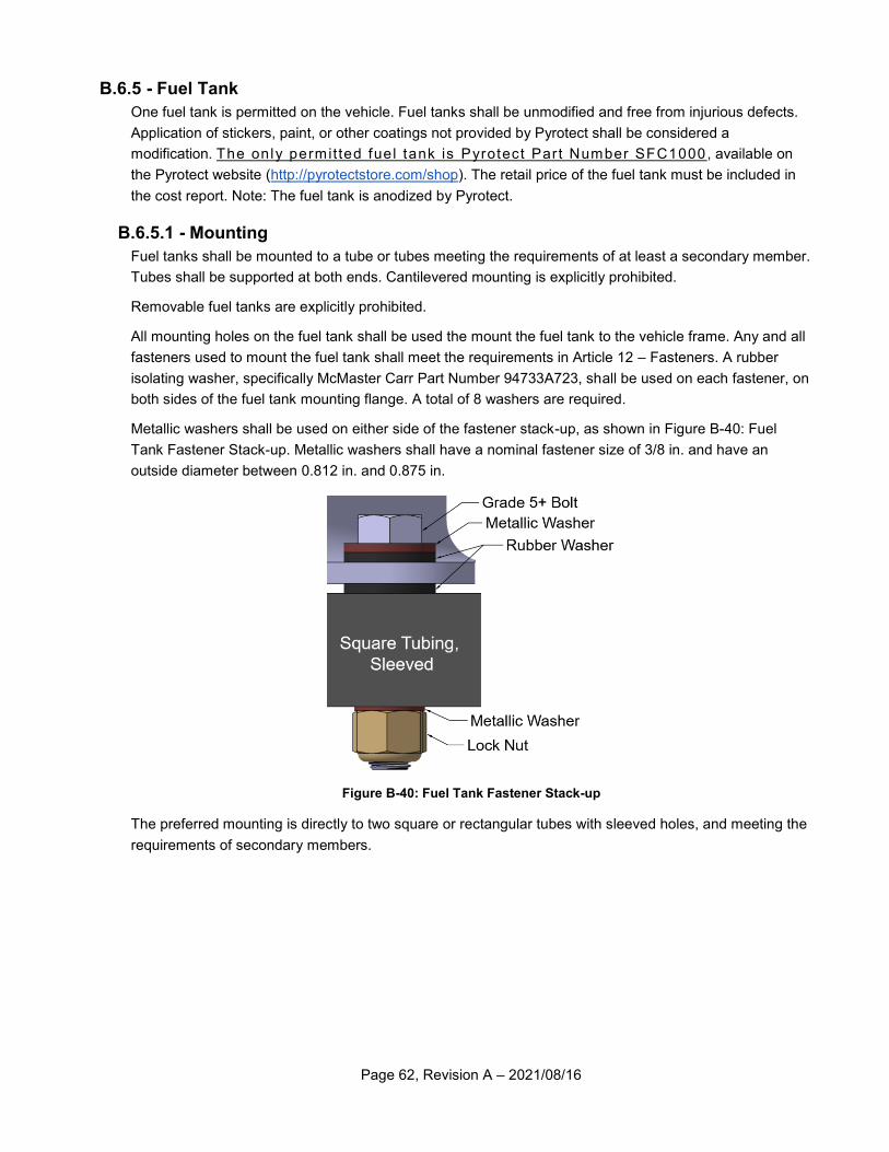
Page 62, Revision A – 2021/08/16
B.6.5 - Fuel Tank
One fuel tank is permitted on the vehicle. Fuel tanks shall be unmodified and free from injurious defects.
Application of stickers, paint, or other coatings not provided by Pyrotect shall be considered a
modification. The only permitted fuel tank is Pyrotect Part Number SFC1000, available on
the Pyrotect website (http://pyrotectstore.com/shop). The retail price of the fuel tank must be included in
the cost report. Note: The fuel tank is anodized by Pyrotect.
B.6.5.1 - Mounting
Fuel tanks shall be mounted to a tube or tubes meeting the requirements of at least a secondary member.
Tubes shall be supported at both ends. Cantilevered mounting is explicitly prohibited.
Removable fuel tanks are explicitly prohibited.
All mounting holes on the fuel tank shall be used the mount the fuel tank to the vehicle frame. Any and all
fasteners used to mount the fuel tank shall meet the requirements in Article 12 – Fasteners. A rubber
isolating washer, specifically McMaster Carr Part Number 94733A723, shall be used on each fastener, on
both sides of the fuel tank mounting flange. A total of 8 washers are required.
Metallic washers shall be used on either side of the fastener stack-up, as shown in Figure B-40: Fuel
Tank Fastener Stack-up. Metallic washers shall have a nominal fastener size of 3/8 in. and have an
outside diameter between 0.812 in. and 0.875 in.
Figure B-40: Fuel Tank Fastener Stack-up
The preferred mounting is directly to two square or rectangular tubes with sleeved holes, and meeting the
requirements of secondary members.
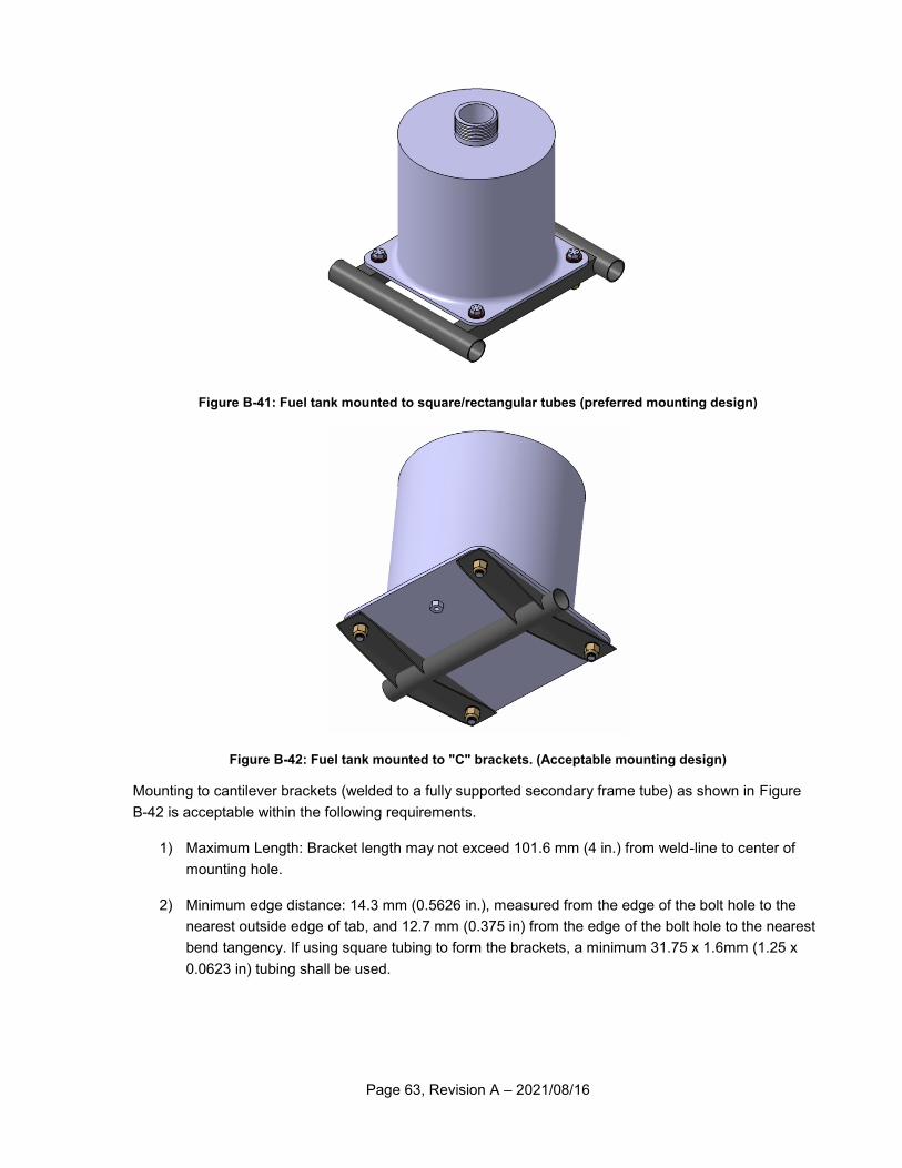
Page 63, Revision A – 2021/08/16
Figure B-41: Fuel tank mounted to square/rectangular tubes (preferred mounting design)
Figure B-42: Fuel tank mounted to "C" brackets. (Acceptable mounting design)
Mounting to cantilever brackets (welded to a fully supported secondary frame tube) as shown in Figure
B-42 is acceptable within the following requirements.
1) Maximum Length: Bracket length may not exceed 101.6 mm (4 in.) from weld-line to center of
mounting hole.
2) Minimum edge distance: 14.3 mm (0.5626 in.), measured from the edge of the bolt hole to the
nearest outside edge of tab, and 12.7 mm (0.375 in) from the edge of the bolt hole to the nearest
bend tangency. If using square tubing to form the brackets, a minimum 31.75 x 1.6mm (1.25 x
0.0623 in) tubing shall be used.
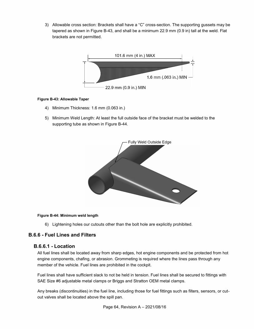
Page 64, Revision A – 2021/08/16
3) Allowable cross section: Brackets shall have a “C” cross-section. The supporting gussets may be
tapered as shown in Figure B-43, and shall be a minimum 22.9 mm (0.9 in) tall at the weld. Flat
brackets are not permitted.
Figure B-43: Allowable Taper
4) Minimum Thickness: 1.6 mm (0.063 in.)
5) Minimum Weld Length: At least the full outside face of the bracket must be welded to the
supporting tube as shown in Figure B-44.
Figure B-44: Minimum weld length
6) Lightening holes our cutouts other than the bolt hole are explicitly prohibited.
B.6.6 - Fuel Lines and Filters
B.6.6.1 - Location
All fuel lines shall be located away from sharp edges, hot engine components and be protected from hot
engine components, chafing, or abrasion. Grommeting is required where the lines pass through any
member of the vehicle. Fuel lines are prohibited in the cockpit.
Fuel lines shall have sufficient slack to not be held in tension. Fuel lines shall be secured to fittings with
SAE Size #6 adjustable metal clamps or Briggs and Stratton OEM metal clamps.
Any breaks (discontinuities) in the fuel line, including those for fuel fittings such as filters, sensors, or cut-
out valves shall be located above the spill pan.
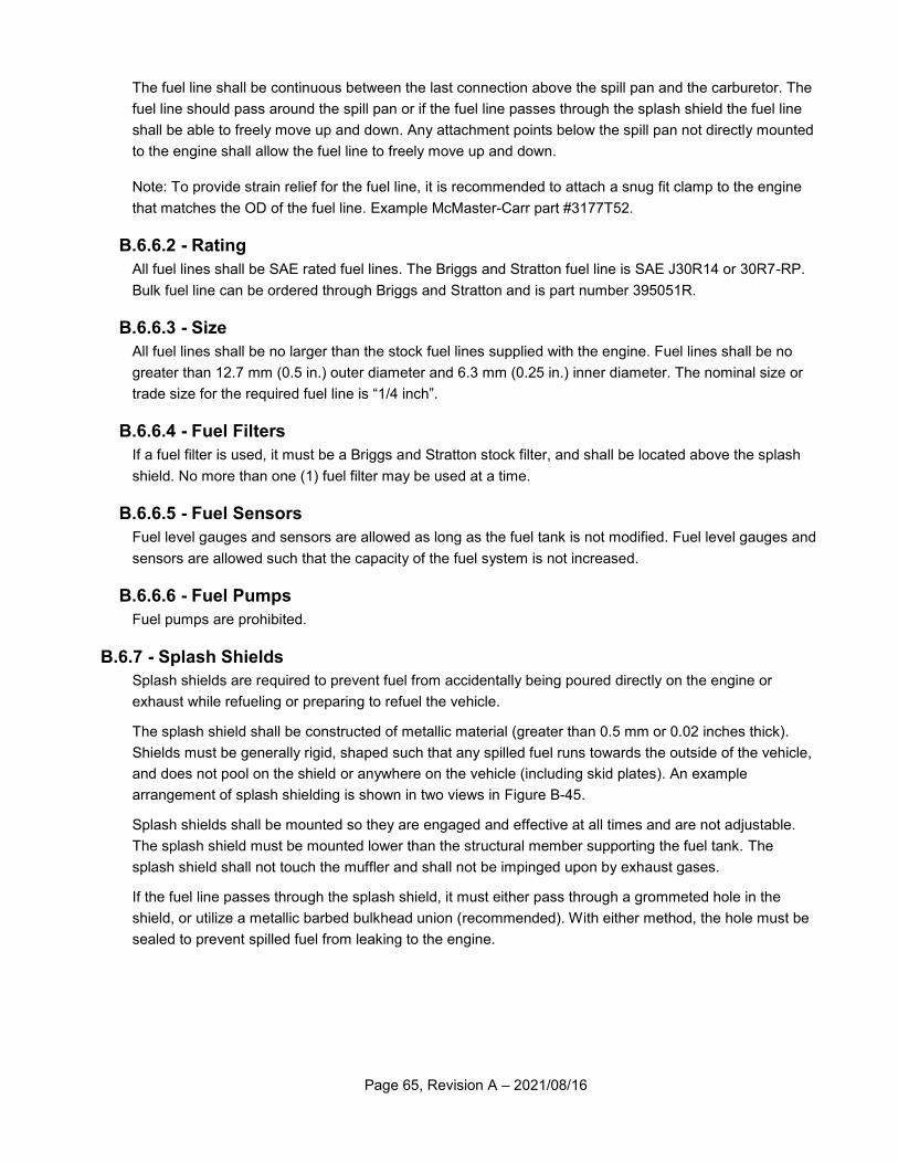
Page 65, Revision A – 2021/08/16
The fuel line shall be continuous between the last connection above the spill pan and the carburetor. The
fuel line should pass around the spill pan or if the fuel line passes through the splash shield the fuel line
shall be able to freely move up and down. Any attachment points below the spill pan not directly mounted
to the engine shall allow the fuel line to freely move up and down.
Note: To provide strain relief for the fuel line, it is recommended to attach a snug fit clamp to the engine
that matches the OD of the fuel line. Example McMaster-Carr part #3177T52.
B.6.6.2 - Rating
All fuel lines shall be SAE rated fuel lines. The Briggs and Stratton fuel line is SAE J30R14 or 30R7-RP.
Bulk fuel line can be ordered through Briggs and Stratton and is part number 395051R.
B.6.6.3 - Size
All fuel lines shall be no larger than the stock fuel lines supplied with the engine. Fuel lines shall be no
greater than 12.7 mm (0.5 in.) outer diameter and 6.3 mm (0.25 in.) inner diameter. The nominal size or
trade size for the required fuel line is “1/4 inch”.
B.6.6.4 - Fuel Filters
If a fuel filter is used, it must be a Briggs and Stratton stock filter, and shall be located above the splash
shield. No more than one (1) fuel filter may be used at a time.
B.6.6.5 - Fuel Sensors
Fuel level gauges and sensors are allowed as long as the fuel tank is not modified. Fuel level gauges and
sensors are allowed such that the capacity of the fuel system is not increased.
B.6.6.6 - Fuel Pumps
Fuel pumps are prohibited.
B.6.7 - Splash Shields
Splash shields are required to prevent fuel from accidentally being poured directly on the engine or
exhaust while refueling or preparing to refuel the vehicle.
The splash shield shall be constructed of metallic material (greater than 0.5 mm or 0.02 inches thick).
Shields must be generally rigid, shaped such that any spilled fuel runs towards the outside of the vehicle,
and does not pool on the shield or anywhere on the vehicle (including skid plates). An example
arrangement of splash shielding is shown in two views in Figure B-45.
Splash shields shall be mounted so they are engaged and effective at all times and are not adjustable.
The splash shield must be mounted lower than the structural member supporting the fuel tank. The
splash shield shall not touch the muffler and shall not be impinged upon by exhaust gases.
If the fuel line passes through the splash shield, it must either pass through a grommeted hole in the
shield, or utilize a metallic barbed bulkhead union (recommended). With either method, the hole must be
sealed to prevent spilled fuel from leaking to the engine.
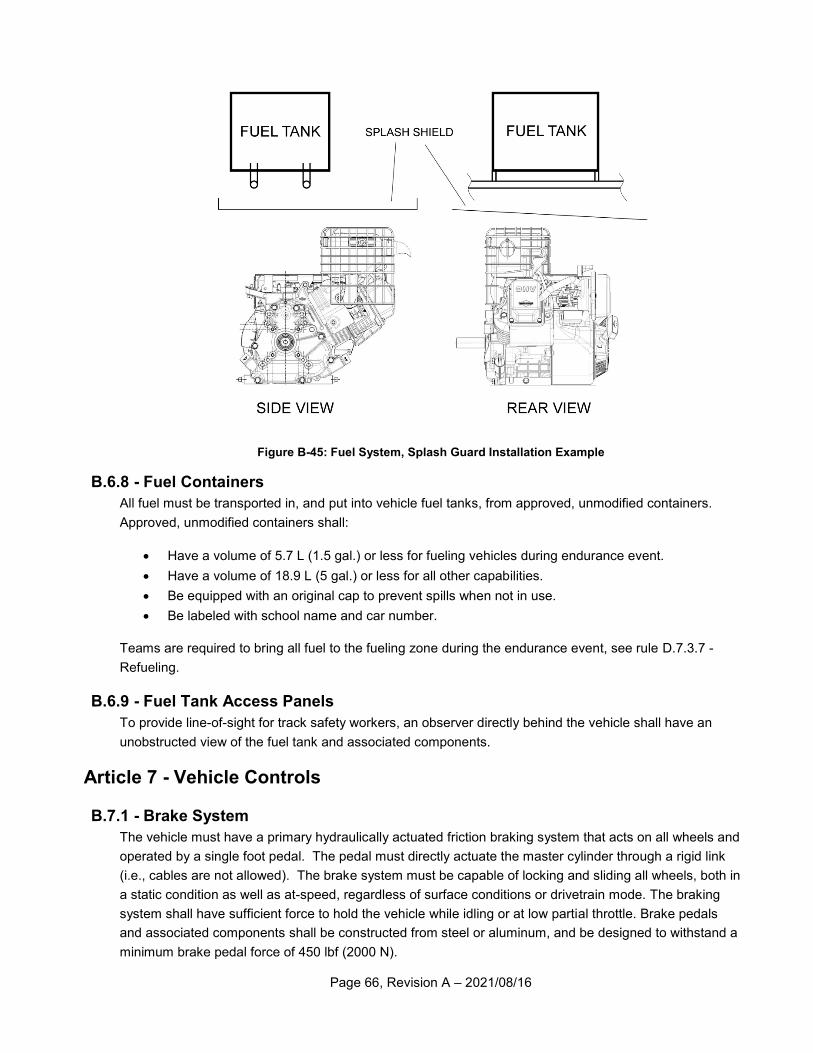
Page 66, Revision A – 2021/08/16
Figure B-45: Fuel System, Splash Guard Installation Example
B.6.8 - Fuel Containers
All fuel must be transported in, and put into vehicle fuel tanks, from approved, unmodified containers.
Approved, unmodified containers shall:
Have a volume of 5.7 L (1.5 gal.) or less for fueling vehicles during endurance event.
Have a volume of 18.9 L (5 gal.) or less for all other capabilities.
Be equipped with an original cap to prevent spills when not in use.
Be labeled with school name and car number.
Teams are required to bring all fuel to the fueling zone during the endurance event, see rule D.7.3.7 -
Refueling.
B.6.9 - Fuel Tank Access Panels
To provide line-of-sight for track safety workers, an observer directly behind the vehicle shall have an
unobstructed view of the fuel tank and associated components.
Article 7 - Vehicle Controls
B.7.1 - Brake System
The vehicle must have a primary hydraulically actuated friction braking system that acts on all wheels and
operated by a single foot pedal. The pedal must directly actuate the master cylinder through a rigid link
(i.e., cables are not allowed). The brake system must be capable of locking and sliding all wheels, both in
a static condition as well as at-speed, regardless of surface conditions or drivetrain mode. The braking
system shall have sufficient force to hold the vehicle while idling or at low partial throttle. Brake pedals
and associated components shall be constructed from steel or aluminum, and be designed to withstand a
minimum brake pedal force of 450 lbf (2000 N).
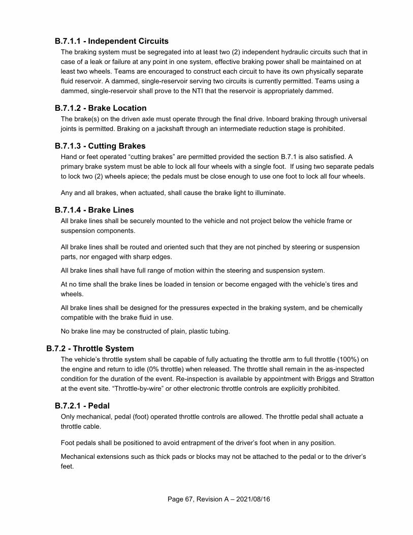
Page 67, Revision A – 2021/08/16
B.7.1.1 - Independent Circuits
The braking system must be segregated into at least two (2) independent hydraulic circuits such that in
case of a leak or failure at any point in one system, effective braking power shall be maintained on at
least two wheels. Teams are encouraged to construct each circuit to have its own physically separate
fluid reservoir. A dammed, single-reservoir serving two circuits is currently permitted. Teams using a
dammed, single-reservoir shall prove to the NTI that the reservoir is appropriately dammed.
B.7.1.2 - Brake Location
The brake(s) on the driven axle must operate through the final drive. Inboard braking through universal
joints is permitted. Braking on a jackshaft through an intermediate reduction stage is prohibited.
B.7.1.3 - Cutting Brakes
Hand or feet operated “cutting brakes” are permitted provided the section B.7.1 is also satisfied. A
primary brake system must be able to lock all four wheels with a single foot. If using two separate pedals
to lock two (2) wheels apiece; the pedals must be close enough to use one foot to lock all four wheels.
Any and all brakes, when actuated, shall cause the brake light to illuminate.
B.7.1.4 - Brake Lines
All brake lines shall be securely mounted to the vehicle and not project below the vehicle frame or
suspension components.
All brake lines shall be routed and oriented such that they are not pinched by steering or suspension
parts, nor engaged with sharp edges.
All brake lines shall have full range of motion within the steering and suspension system.
At no time shall the brake lines be loaded in tension or become engaged with the vehicle’s tires and
wheels.
All brake lines shall be designed for the pressures expected in the braking system, and be chemically
compatible with the brake fluid in use.
No brake line may be constructed of plain, plastic tubing.
B.7.2 - Throttle System
The vehicle’s throttle system shall be capable of fully actuating the throttle arm to full throttle (100%) on
the engine and return to idle (0% throttle) when released. The throttle shall remain in the as-inspected
condition for the duration of the event. Re-inspection is available by appointment with Briggs and Stratton
at the event site. “Throttle-by-wire” or other electronic throttle controls are explicitly prohibited.
B.7.2.1 - Pedal
Only mechanical, pedal (foot) operated throttle controls are allowed. The throttle pedal shall actuate a
throttle cable.
Foot pedals shall be positioned to avoid entrapment of the driver’s foot when in any position.
Mechanical extensions such as thick pads or blocks may not be attached to the pedal or to the driver’s
feet.
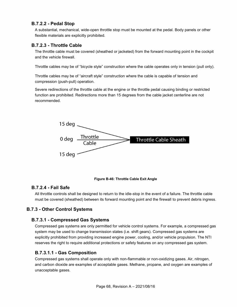
Page 68, Revision A – 2021/08/16
B.7.2.2 - Pedal Stop
A substantial, mechanical, wide-open throttle stop must be mounted at the pedal. Body panels or other
flexible materials are explicitly prohibited.
B.7.2.3 - Throttle Cable
The throttle cable must be covered (sheathed or jacketed) from the forward mounting point in the cockpit
and the vehicle firewall.
Throttle cables may be of “bicycle style” construction where the cable operates only in tension (pull only).
Throttle cables may be of “aircraft style” construction where the cable is capable of tension and
compression (push-pull) operation.
Severe redirections of the throttle cable at the engine or the throttle pedal causing binding or restricted
function are prohibited. Redirections more than 15 degrees from the cable jacket centerline are not
recommended.
Figure B-46: Throttle Cable Exit Angle
B.7.2.4 - Fail Safe
All throttle controls shall be designed to return to the idle-stop in the event of a failure. The throttle cable
must be covered (sheathed) between its forward mounting point and the firewall to prevent debris ingress.
B.7.3 - Other Control Systems
B.7.3.1 - Compressed Gas Systems
Compressed gas systems are only permitted for vehicle control systems. For example, a compressed gas
system may be used to change transmission states (i.e. shift gears). Compressed gas systems are
explicitly prohibited from providing increased engine power, cooling, and/or vehicle propulsion. The NTI
reserves the right to require additional protections or safety features on any compressed gas system.
B.7.3.1.1 - Gas Composition
Compressed gas systems shall operate only with non-flammable or non-oxidizing gases. Air, nitrogen,
and carbon dioxide are examples of acceptable gases. Methane, propane, and oxygen are examples of
unacceptable gases.
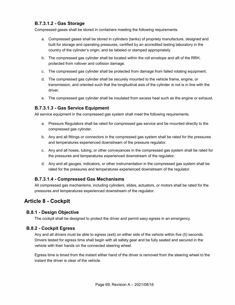
Page 69, Revision A – 2021/08/16
B.7.3.1.2 - Gas Storage
Compressed gases shall be stored in containers meeting the following requirements.
a. Compressed gases shall be stored in cylinders (tanks) of propriety manufacture, designed and
built for storage and operating pressures, certified by an accredited testing laboratory in the
country of the cylinder’s origin, and be labeled or stamped appropriately.
b. The compressed gas cylinder shall be located within the roll envelope and aft of the RRH,
protected from rollover and collision damage.
c. The compressed gas cylinder shall be protected from damage from failed rotating equipment.
d. The compressed gas cylinder shall be securely mounted to the vehicle frame, engine, or
transmission, and oriented such that the longitudinal axis of the cylinder is not is in line with the
driver.
e. The compressed gas cylinder shall be insulated from excess heat such as the engine or exhaust.
B.7.3.1.3 - Gas Service Equipment
All service equipment in the compressed gas system shall meet the following requirements.
a. Pressure Regulators shall be rated for compressed gas service and be mounted directly to the
compressed gas cylinder.
b. Any and all fittings or connectors in the compressed gas system shall be rated for the pressures
and temperatures experienced downstream of the pressure regulator.
c. Any and all hoses, tubing, or other conveyances in the compressed gas system shall be rated for
the pressures and temperatures experienced downstream of the regulator.
d. Any and all gauges, indicators, or other instrumentation in the compressed gas system shall be
rated for the pressures and temperatures experienced downstream of the regulator.
B.7.3.1.4 - Compressed Gas Mechanisms
All compressed gas mechanisms, including cylinders, slides, actuators, or motors shall be rated for the
pressures and temperatures experienced downstream of the regulator.
Article 8 - Cockpit
B.8.1 - Design Objective
The cockpit shall be designed to protect the driver and permit easy egress in an emergency.
B.8.2 - Cockpit Egress
Any and all drivers must be able to egress (exit) on either side of the vehicle within five (5) seconds.
Drivers tested for egress time shall begin with all safety gear and be fully seated and secured in the
vehicle with their hands on the connected steering wheel.
Egress time is timed from the instant either hand of the driver is removed from the steering wheel to the
instant the driver is clear of the vehicle.
Page 70, Revision A – 2021/08/16
The NTI will select one or more drivers to perform the cockpit egress test. Drivers unable to demonstrate
successful egress will have their driver status revoked. Each team is required to have a minimum of two
designated drivers.
B.8.3 - Firewall
All vehicles shall have a firewall separating the cockpit from the engine and fuel tank compartments. The
firewall shall be constructed of metal, at least 0.50 mm (0.02 in.) thick. The firewall shall be mounted in
the plane of the RRH and cover the area between the ALC and BLC.
Multiple metal panels may be used to form the firewall, provided there are no gaps between the joints.
Select cutouts are allowed for control cables, brake lines, or electrical cables, provided the cutouts have
proper grommeting and sealing.
Large cutouts in the firewall are explicitly prohibited. Large cutouts include those for CVT ventilation, and
other similar items. Air intakes may not penetrate the firewall and must remain within the roll envelope.
Cutouts for drivetrain components are permitted.
B.8.4 - Front or Mid-Engine Vehicles
If the mounting points of the engine are completely forward of the RRH, then a firewall is not required to
cover the area between within the plane of the RRH and between the LC’s of the RRH. If the mounting
points of the engine are completely forward of the RRH, the following requirements must be met:
a. The fuel tank shall be enclosed in a sealed container that prevents fuel from leaking in the event
of a fuel tank failure.
b. Splash shields must prevent fuel from being poured anywhere in the cockpit area during fueling.
c. The engine shall be completely enclosed and the enclosure shall protect the driver in the event of
an engine failure. The engine enclosure shall be metal and meet the requirements of Article 9 -
Powertrain Guards.
d. Engine enclosures must prevent fuel from spilling into the cockpit should the vehicle be involved
in a collision or roll-over.
e. All engine compartment venting shall be directed away from the cockpit.
f. The driver must be able to egress from both sides of the vehicle.
g. The engine exhaust shall not exit in the direction of the driver and shall be shielded from contact
by track workers and competition officials.
h. A panel, 300 mm x 300 mm (12 in. x 12 in.), shall be affixed to the vehicle in the plane of the
RRH, on the right side of the driver’s head, and above the shoulder level of the tallest driver. This
panel shall be used to affix the Technical Inspection sticker, and shall be easily viewed by track
workers and competition officials.
Page 71, Revision A – 2021/08/16
B.8.5 - Body Panels
The cockpit must be protected with body panels that completely cover the area between the LFS and the
SIM. No gaps can exist that are larger than 6.35 mm (0.25 in) and will be checked with a 6.35 mm (0.25
in dowel rod). These panels must be made of puncture resistant material, including: plastic, fiberglass,
metal, or similar material. They must be designed to prevent debris and foreign object intrusion into the
driver compartment. The panels must be mounted securely to the frame using sound engineering
practices (cable ties or hook-and-loop fastening is not acceptable).
Note: Quick d isconnect or easi ly access ib le fasteners for body panels are
recommended, and fac i l i tate a faster technical inspect ion process.
B.8.6 - Skid Plate
The cockpit must be fitted with a skid plate (belly pan) over the entire length of the cockpit, so that the
driver cannot contact the ground and is protected from debris while seated normally. Skid plate material
shall be metal, fiberglass, plastic, or similar material. Skid plates shall be designed to prevent debris and
foreign object intrusion into the driver compartment. Expanded metal, fabric, or perforated panels are not
allowed. Skid plates extending aft of the firewall shall have features to prevent leaking fuel from entering
the cockpit.
B.8.7 - Shielding for Legs and Feet
B.8.7.1 - Linkages
All steering or suspension links exposed in the cockpit shall be shielded with a sturdy, robust, metal
cover. The shielding shall be continuous and extend the full width of the cockpit (from the left body panel
to the right body panel) and shall prevent the driver’s legs and feet from coming in contact, becoming
entangled, or struck by the steering or suspension components during operation or a failure. No gaps
may exist that are larger than 6.35 mm (0.25 in).
Note: Quick d isconnect or easi ly access ib le fasteners for cockpit steer ing &
suspens ion covers are recommended, and faci l i tate a faster technical inspect ion
process.
B.8.7.2 - Universal Joints
Universal joints in the steering system or 4WD/AWD system and near the driver’s feet shall be shielded or
sealed such that the driver may not become entangled in the joint.
Caution: Loose shoelaces can and have become entangled in universal joints and
steering parts and will hinder driver egress from the cockpit .
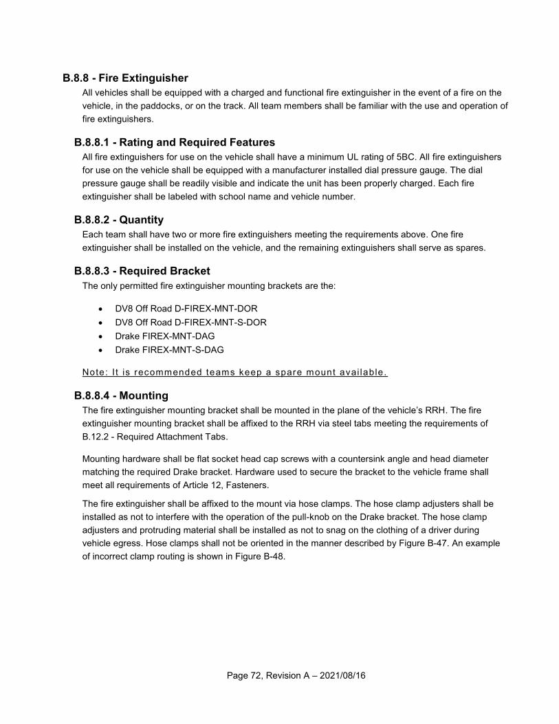
Page 72, Revision A – 2021/08/16
B.8.8 - Fire Extinguisher
All vehicles shall be equipped with a charged and functional fire extinguisher in the event of a fire on the
vehicle, in the paddocks, or on the track. All team members shall be familiar with the use and operation of
fire extinguishers.
B.8.8.1 - Rating and Required Features
All fire extinguishers for use on the vehicle shall have a minimum UL rating of 5BC. All fire extinguishers
for use on the vehicle shall be equipped with a manufacturer installed dial pressure gauge. The dial
pressure gauge shall be readily visible and indicate the unit has been properly charged. Each fire
extinguisher shall be labeled with school name and vehicle number.
B.8.8.2 - Quantity
Each team shall have two or more fire extinguishers meeting the requirements above. One fire
extinguisher shall be installed on the vehicle, and the remaining extinguishers shall serve as spares.
B.8.8.3 - Required Bracket
The only permitted fire extinguisher mounting brackets are the:
DV8 Off Road D-FIREX-MNT-DOR
DV8 Off Road D-FIREX-MNT-S-DOR
Drake FIREX-MNT-DAG
Drake FIREX-MNT-S-DAG
Note: I t is recommended teams keep a spare mount avai lable.
B.8.8.4 - Mounting
The fire extinguisher mounting bracket shall be mounted in the plane of the vehicle’s RRH. The fire
extinguisher mounting bracket shall be affixed to the RRH via steel tabs meeting the requirements of
B.12.2 - Required Attachment Tabs.
Mounting hardware shall be flat socket head cap screws with a countersink angle and head diameter
matching the required Drake bracket. Hardware used to secure the bracket to the vehicle frame shall
meet all requirements of Article 12, Fasteners.
The fire extinguisher shall be affixed to the mount via hose clamps. The hose clamp adjusters shall be
installed as not to interfere with the operation of the pull-knob on the Drake bracket. The hose clamp
adjusters and protruding material shall be installed as not to snag on the clothing of a driver during
vehicle egress. Hose clamps shall not be oriented in the manner described by Figure B-47. An example
of incorrect clamp routing is shown in Figure B-48.
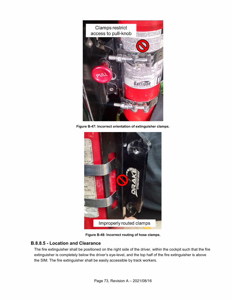
Page 73, Revision A – 2021/08/16
Figure B-47: Incorrect orientation of extinguisher clamps.
Figure B-48: Incorrect routing of hose clamps.
B.8.8.5 - Location and Clearance
The fire extinguisher shall be positioned on the right side of the driver, within the cockpit such that the fire
extinguisher is completely below the driver’s eye-level, and the top half of the fire extinguisher is above
the SIM. The fire extinguisher shall be easily accessible by track workers.
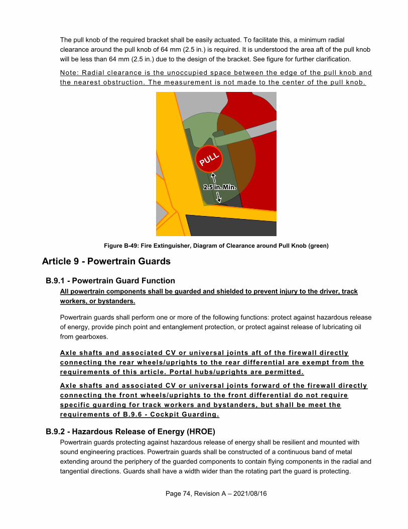
Page 74, Revision A – 2021/08/16
The pull knob of the required bracket shall be easily actuated. To facilitate this, a minimum radial
clearance around the pull knob of 64 mm (2.5 in.) is required. It is understood the area aft of the pull knob
will be less than 64 mm (2.5 in.) due to the design of the bracket. See figure for further clarification.
Note: Radia l c learance is the unoccupied space between the edge of the pul l knob and
the nearest obstruct ion. The measurement is not made to the center of the pul l knob.
Figure B-49: Fire Extinguisher, Diagram of Clearance around Pull Knob (green)
Article 9 - Powertrain Guards
B.9.1 - Powertrain Guard Function
All powertrain components shall be guarded and shielded to prevent injury to the driver, track
workers, or bystanders.
Powertrain guards shall perform one or more of the following functions: protect against hazardous release
of energy, provide pinch point and entanglement protection, or protect against release of lubricating oil
from gearboxes.
Axle shafts and associated CV or universal jo ints aft of the f irewal l directly
connecting the rear wheels/uprights to the rear differential are exempt from the
requirements of this art icle. Portal hubs/uprights are permitted.
Axle shafts and associated CV or universal jo ints forward of the f i rewall directly
connecting the front wheels/uprights to the front different ial do not require
specif ic guarding for track workers and bystanders, but shall be meet the
requirements of B.9.6 - Cockpit Guarding .
B.9.2 - Hazardous Release of Energy (HROE)
Powertrain guards protecting against hazardous release of energy shall be resilient and mounted with
sound engineering practices. Powertrain guards shall be constructed of a continuous band of metal
extending around the periphery of the guarded components to contain flying components in the radial and
tangential directions. Guards shall have a width wider than the rotating part the guard is protecting.
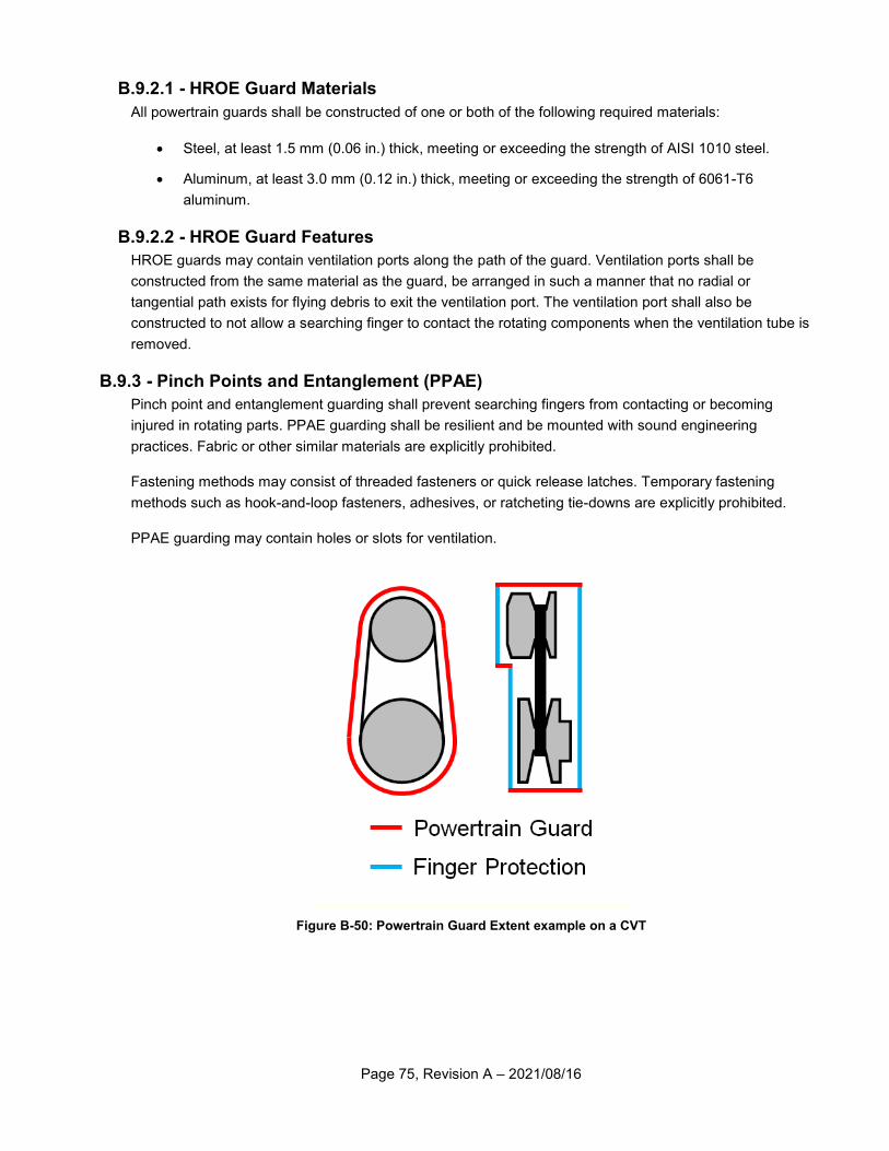
Page 75, Revision A – 2021/08/16
B.9.2.1 - HROE Guard Materials
All powertrain guards shall be constructed of one or both of the following required materials:
Steel, at least 1.5 mm (0.06 in.) thick, meeting or exceeding the strength of AISI 1010 steel.
Aluminum, at least 3.0 mm (0.12 in.) thick, meeting or exceeding the strength of 6061-T6
aluminum.
B.9.2.2 - HROE Guard Features
HROE guards may contain ventilation ports along the path of the guard. Ventilation ports shall be
constructed from the same material as the guard, be arranged in such a manner that no radial or
tangential path exists for flying debris to exit the ventilation port. The ventilation port shall also be
constructed to not allow a searching finger to contact the rotating components when the ventilation tube is
removed.
B.9.3 - Pinch Points and Entanglement (PPAE)
Pinch point and entanglement guarding shall prevent searching fingers from contacting or becoming
injured in rotating parts. PPAE guarding shall be resilient and be mounted with sound engineering
practices. Fabric or other similar materials are explicitly prohibited.
Fastening methods may consist of threaded fasteners or quick release latches. Temporary fastening
methods such as hook-and-loop fasteners, adhesives, or ratcheting tie-downs are explicitly prohibited.
PPAE guarding may contain holes or slots for ventilation.
Figure B-50: Powertrain Guard Extent example on a CVT
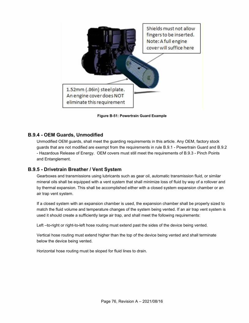
Page 76, Revision A – 2021/08/16
Figure B-51: Powertrain Guard Example
B.9.4 - OEM Guards, Unmodified
Unmodified OEM guards, shall meet the guarding requirements in this article. Any OEM, factory stock
guards that are not modified are exempt from the requirements in rule B.9.1 - Powertrain Guard and B.9.2
- Hazardous Release of Energy. OEM covers must still meet the requirements of B.9.3 - Pinch Points
and Entanglement.
B.9.5 - Drivetrain Breather / Vent System
Gearboxes and transmissions using lubricants such as gear oil, automatic transmission fluid, or similar
mineral oils shall be equipped with a vent system that shall minimize loss of fluid by way of a rollover and
by thermal expansion. This shall be accomplished either with a closed system expansion chamber or an
air trap vent system.
If a closed system with an expansion chamber is used, the expansion chamber shall be properly sized to
match the fluid volume and temperature changes of the system being vented. If an air trap vent system is
used it should create a sufficiently large air trap, and shall meet the following requirements:
Left –to-right or right-to-left hose routing must extend past the sides of the device being vented.
Vertical hose routing must extend higher than the top of the device being vented and shall terminate
below the device being vented.
Horizontal hose routing must be sloped for fluid lines to drain.
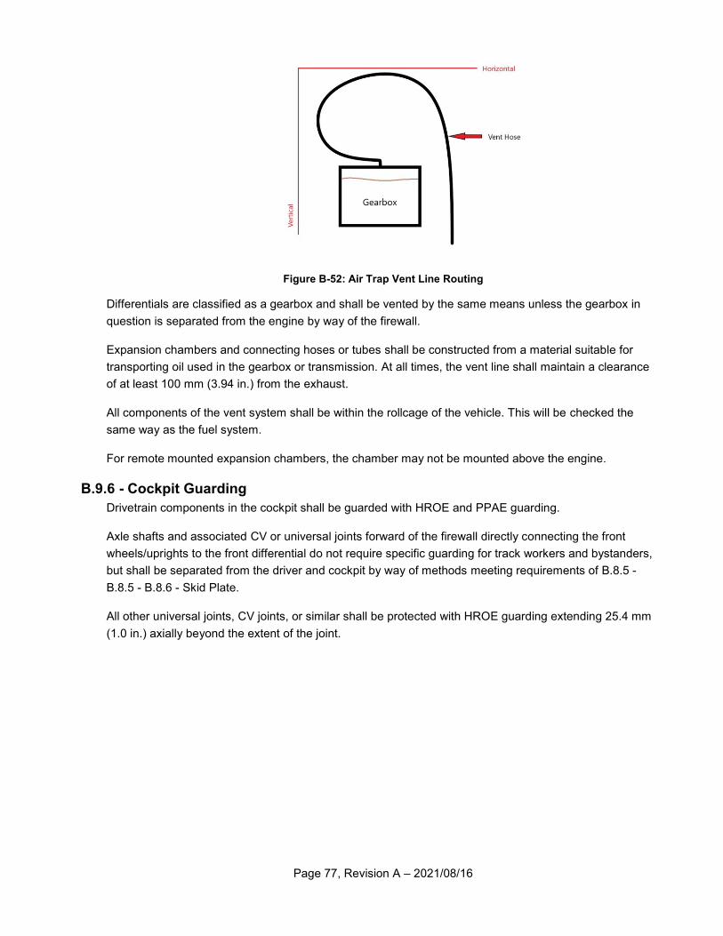
Page 77, Revision A – 2021/08/16
Figure B-52: Air Trap Vent Line Routing
Differentials are classified as a gearbox and shall be vented by the same means unless the gearbox in
question is separated from the engine by way of the firewall.
Expansion chambers and connecting hoses or tubes shall be constructed from a material suitable for
transporting oil used in the gearbox or transmission. At all times, the vent line shall maintain a clearance
of at least 100 mm (3.94 in.) from the exhaust.
All components of the vent system shall be within the rollcage of the vehicle. This will be checked the
same way as the fuel system.
For remote mounted expansion chambers, the chamber may not be mounted above the engine.
B.9.6 - Cockpit Guarding
Drivetrain components in the cockpit shall be guarded with HROE and PPAE guarding.
Axle shafts and associated CV or universal joints forward of the firewall directly connecting the front
wheels/uprights to the front differential do not require specific guarding for track workers and bystanders,
but shall be separated from the driver and cockpit by way of methods meeting requirements of B.8.5 -
B.8.5 - B.8.6 - Skid Plate.
All other universal joints, CV joints, or similar shall be protected with HROE guarding extending 25.4 mm
(1.0 in.) axially beyond the extent of the joint.
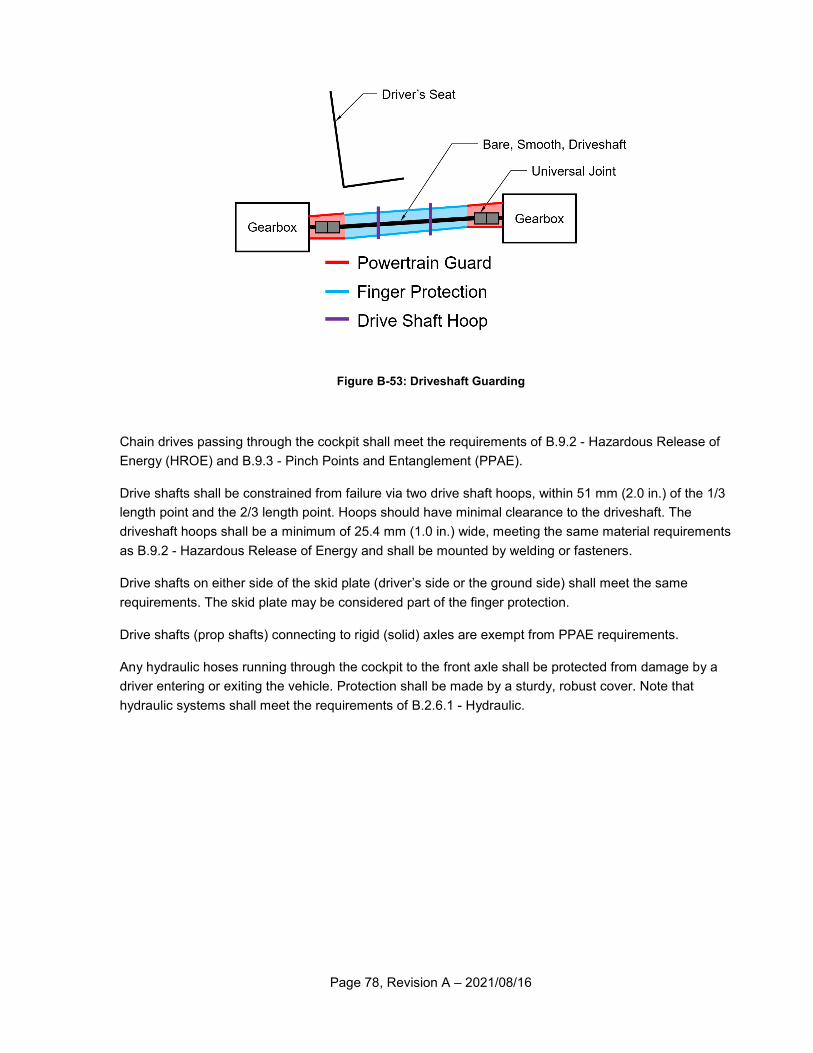
Page 78, Revision A – 2021/08/16
Figure B-53: Driveshaft Guarding
Chain drives passing through the cockpit shall meet the requirements of B.9.2 - Hazardous Release of
Energy (HROE) and B.9.3 - Pinch Points and Entanglement (PPAE).
Drive shafts shall be constrained from failure via two drive shaft hoops, within 51 mm (2.0 in.) of the 1/3
length point and the 2/3 length point. Hoops should have minimal clearance to the driveshaft. The
driveshaft hoops shall be a minimum of 25.4 mm (1.0 in.) wide, meeting the same material requirements
as B.9.2 - Hazardous Release of Energy and shall be mounted by welding or fasteners.
Drive shafts on either side of the skid plate (driver’s side or the ground side) shall meet the same
requirements. The skid plate may be considered part of the finger protection.
Drive shafts (prop shafts) connecting to rigid (solid) axles are exempt from PPAE requirements.
Any hydraulic hoses running through the cockpit to the front axle shall be protected from damage by a
driver entering or exiting the vehicle. Protection shall be made by a sturdy, robust cover. Note that
hydraulic systems shall meet the requirements of B.2.6.1 - Hydraulic.
Page 79, Revision A – 2021/08/16
Article 10 - Electrical System
A minimum electrical system comprising of at least two engine kill switches, a brake light, brake switch,
battery, and associated wiring is required. The vehicle electrical system shall be designed and
constructed in accordance with good engineering and electrical practices. Brake lights, reverse lights and
alarms shall operate regardless of kill switch setting. Brake lights, reverse lights and alarms shall be
powered and functional at all times.
B.10.1 - Power Sources
B.10.1.1 - Batteries
B.10.1.1.1 - Mounting
All batteries shall be mounted with sound engineering practices and not come loose during normal
operation, a collision or rollover. Battery terminals shall be insulated and protected against an electrical
short.
B.10.1.1.2 - Sealing
All batteries must be factory sealed and maintenance free. Batteries shall be incapable of being opened
or serviced and not leak in the event of a collision or rollover.
B.10.1.1.3 - Capacity
Any battery used for safety appliances, (brake light, reverse light, reverse alarm), shall have sufficient
electrical capacity to last the entire length of the endurance event.
B.10.1.2 - Engine Alternator
If an alternator is used, only approved engine alternators may be selected. See rule B.2.7.15 - Alternator
for further information.
B.10.1.3 - Solar Panels
Solar panels are permitted to recharge on-board batteries.
B.10.2 - Wiring and Connectors
All vehicle wiring and connectors shall be cleanly and neatly installed. Wiring shall be routed away from
sources of excessive heat, abrasion, chafing, and possible short circuit. Wiring shall be installed and
routed such that it does not become a hazard to cockpit egress.
B.10.3 - Engine Kill Switches
B.10.3.1 - Quantity
Each vehicle shall be equipped with a minimum of two (2) engine kill switches.
B.10.3.2 - Required Switch
The vehicle shall be equipped with one or more of the following required switches:
Polaris Part 4015321 or 4019114
Ski-Doo Part 01-171 (http://www.mfgsupply.com/01-171.html)
WPS 27-0152 (http://www.parkeryamaha.com/skidoostopswitch.aspx)
WPS 27-0154(http://www.parkeryamaha.com/skidoostopswitch.aspx)
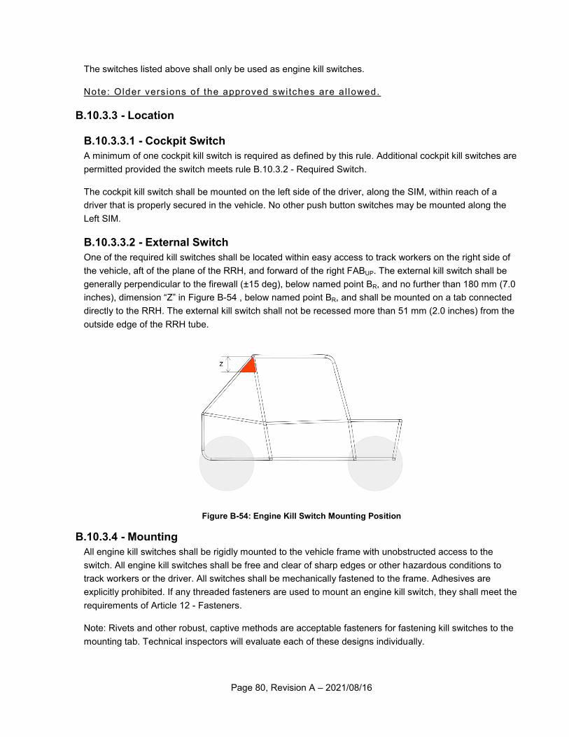
Page 80, Revision A – 2021/08/16
The switches listed above shall only be used as engine kill switches.
Note: Older vers ions of the approved switches are a l lowed.
B.10.3.3 - Location
B.10.3.3.1 - Cockpit Switch
A minimum of one cockpit kill switch is required as defined by this rule. Additional cockpit kill switches are
permitted provided the switch meets rule B.10.3.2 - Required Switch.
The cockpit kill switch shall be mounted on the left side of the driver, along the SIM, within reach of a
driver that is properly secured in the vehicle. No other push button switches may be mounted along the
Left SIM.
B.10.3.3.2 - External Switch
One of the required kill switches shall be located within easy access to track workers on the right side of
the vehicle, aft of the plane of the RRH, and forward of the right FABUP. The external kill switch shall be
generally perpendicular to the firewall (±15 deg), below named point BR, and no further than 180 mm (7.0
inches), dimension “Z” in Figure B-54 , below named point BR, and shall be mounted on a tab connected
directly to the RRH. The external kill switch shall not be recessed more than 51 mm (2.0 inches) from the
outside edge of the RRH tube.
Figure B-54: Engine Kill Switch Mounting Position
B.10.3.4 - Mounting
All engine kill switches shall be rigidly mounted to the vehicle frame with unobstructed access to the
switch. All engine kill switches shall be free and clear of sharp edges or other hazardous conditions to
track workers or the driver. All switches shall be mechanically fastened to the frame. Adhesives are
explicitly prohibited. If any threaded fasteners are used to mount an engine kill switch, they shall meet the
requirements of Article 12 - Fasteners.
Note: Rivets and other robust, captive methods are acceptable fasteners for fastening kill switches to the
mounting tab. Technical inspectors will evaluate each of these designs individually.
Page 81, Revision A – 2021/08/16
B.10.4 - Signaling
B.10.4.1 - Brake Light
All vehicles are required to have a functional brake light to signal to other drivers the vehicle is stopping or
slowing down.
B.10.4.1.1 - Required Brake Light
Only the following brake lights are permitted. Brake lights not listed are explicitly prohibited. Modification
of the brake light from the OEM design is explicitly prohibited. All brake lights shall be configured to be
fully illuminated when the brakes are applied, and completely extinguished with the brakes are released.
Polaris Part # 2411450
Polaris Part # 2411099
Polaris Part # 2411092-432
Haul-Master – Part # 93263
Command Electronics Part # 003-6018R
Command Electronics Part # 003-6016
B.10.4.1.2 - Location and Orientation
The vehicle brake light shall have a resilient and durable mount and be positioned at a minimum of 1000
mm (39.4 in.) above the ground. The vehicle brake light shall be oriented to be visible to trailing vehicles
and shine parallel to the ground or at a slightly downward angle. Brake lights angled (aimed) above a
horizontal plane are not permitted.
B.10.4.1.3 - Brake Light Switch
The brake light shall be activated only by a hydraulic pressure switch installed in the brake hydraulic lines.
Each independent hydraulic brake circuit must be equipped with a hydraulic pressure switch. Cutting
brakes are required to activate the brake light by way of a hydraulic pressure switch.
Note: Mechanical swi tches , push or pul l , are expl ic i t l y prohib ited.
B.10.4.2 - Reverse Light
Vehicles with a reverse gear shall be equipped with a reverse light. The reverse light shall illuminate
when the vehicle is shifted to reverse gear and is extinguished when the vehicle is shifted out of reverse
gear.
B.10.4.2.1 - Specification
Reverse lights shall be marked with an SAE “R” on the lens of the reverse light and be of LED design,
equal to or exceeding the SAE standard J759.
B.10.4.2.2 - Location and Orientation
The reverse light shall have a resilient and durable mount and be positioned at a minimum of 700 mm
(27.6 in.) above the ground. The reverse light shall be oriented to be visible to trailing vehicles and shine
generally parallel to the ground.
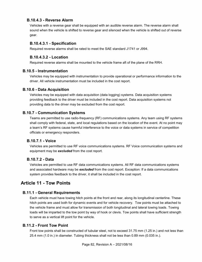
Page 82, Revision A – 2021/08/16
B.10.4.3 - Reverse Alarm
Vehicles with a reverse gear shall be equipped with an audible reverse alarm. The reverse alarm shall
sound when the vehicle is shifted to reverse gear and silenced when the vehicle is shifted out of reverse
gear.
B.10.4.3.1 - Specification
Required reverse alarms shall be rated to meet the SAE standard J1741 or J994.
B.10.4.3.2 - Location
Required reverse alarms shall be mounted to the vehicle frame aft of the plane of the RRH.
B.10.5 - Instrumentation
Vehicles may be equipped with instrumentation to provide operational or performance information to the
driver. All vehicle instrumentation must be included in the cost report.
B.10.6 - Data Acquisition
Vehicles may be equipped with data acquisition (data logging) systems. Data acquisition systems
providing feedback to the driver must be included in the cost report. Data acquisition systems not
providing data to the driver may be excluded from the cost report.
B.10.7 - Communication Systems
Teams are permitted to use radio-frequency (RF) communications systems. Any team using RF systems
shall comply with federal, state, and local regulations based on the location of the event. At no point may
a team’s RF systems cause harmful interference to the voice or data systems in service of competition
officials or emergency responders.
B.10.7.1 - Voice
Vehicles are permitted to use RF voice communications systems. RF Voice communication systems and
equipment may be excluded from the cost report.
B.10.7.2 - Data
Vehicles are permitted to use RF data communications systems. All RF data communications systems
and associated hardware may be excluded from the cost report. Exception: If a data communications
system provides feedback to the driver, it shall be included in the cost report.
Article 11 - Tow Points
B.11.1 - General Requirements
Each vehicle must have towing hitch points at the front and rear, along its longitudinal centerline. These
hitch points are used both for dynamic events and for vehicle recovery. Tow points must be attached to
the vehicle frame and must allow for transmission of both longitudinal and lateral towing loads. Towing
loads will be imparted to the tow point by way of hook or clevis. Tow points shall have sufficient strength
to serve as a vertical lift point for the vehicle.
B.11.2 - Front Tow Point
Front tow points shall be constructed of tubular steel, not to exceed 31.75 mm (1.25 in.) and not less than
25.4 mm (1.0 in.) in diameter. Tubing thickness shall not be less than 0.89 mm (0.035 in.).
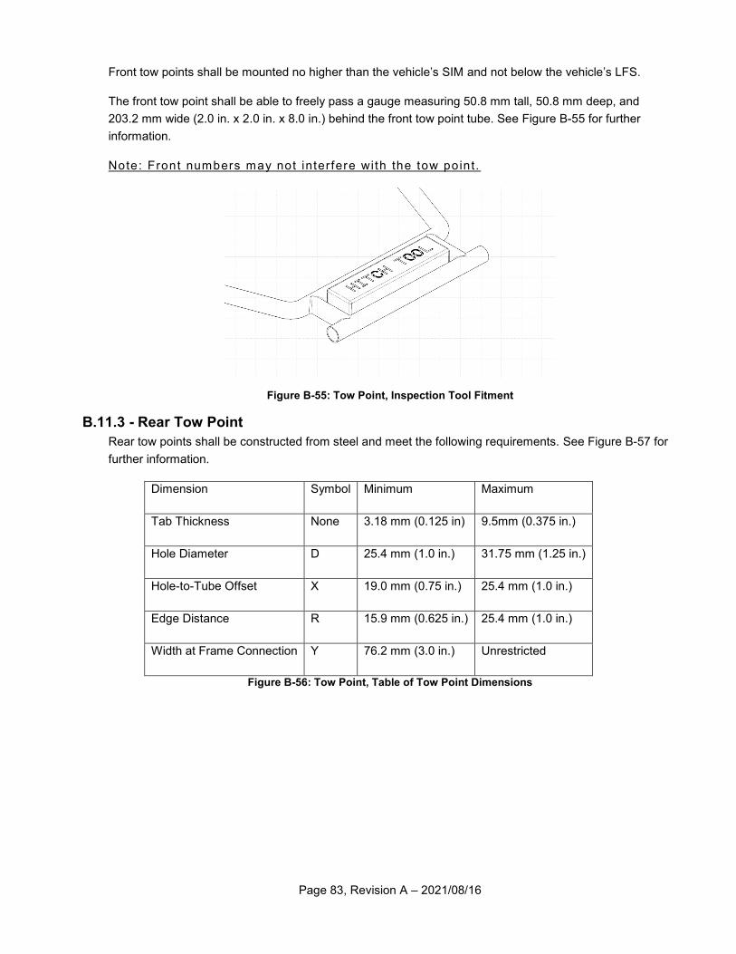
Page 83, Revision A – 2021/08/16
Front tow points shall be mounted no higher than the vehicle’s SIM and not below the vehicle’s LFS.
The front tow point shall be able to freely pass a gauge measuring 50.8 mm tall, 50.8 mm deep, and
203.2 mm wide (2.0 in. x 2.0 in. x 8.0 in.) behind the front tow point tube. See Figure B-55 for further
information.
Note: Front numbers may not interfere wi th the tow point.
Figure B-55: Tow Point, Inspection Tool Fitment
B.11.3 - Rear Tow Point
Rear tow points shall be constructed from steel and meet the following requirements. See Figure B-57 for
further information.
Dimension Symbol Minimum Maximum
Tab Thickness None 3.18 mm (0.125 in) 9.5mm (0.375 in.)
Hole Diameter D 25.4 mm (1.0 in.) 31.75 mm (1.25 in.)
Hole-to-Tube Offset X 19.0 mm (0.75 in.) 25.4 mm (1.0 in.)
Edge Distance R 15.9 mm (0.625 in.) 25.4 mm (1.0 in.)
Width at Frame Connection Y 76.2 mm (3.0 in.) Unrestricted
Figure B-56: Tow Point, Table of Tow Point Dimensions
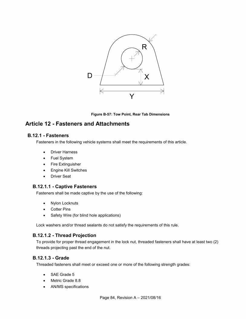
Page 84, Revision A – 2021/08/16
Figure B-57: Tow Point, Rear Tab Dimensions
Article 12 - Fasteners and Attachments
B.12.1 - Fasteners
Fasteners in the following vehicle systems shall meet the requirements of this article.
Driver Harness
Fuel System
Fire Extinguisher
Engine Kill Switches
Driver Seat
B.12.1.1 - Captive Fasteners
Fasteners shall be made captive by the use of the following:
Nylon Locknuts
Cotter Pins
Safety Wire (for blind hole applications)
Lock washers and/or thread sealants do not satisfy the requirements of this rule.
B.12.1.2 - Thread Projection
To provide for proper thread engagement in the lock nut, threaded fasteners shall have at least two (2)
threads projecting past the end of the nut.
B.12.1.3 - Grade
Threaded fasteners shall meet or exceed one or more of the following strength grades:
SAE Grade 5
Metric Grade 8.8
AN/MS specifications
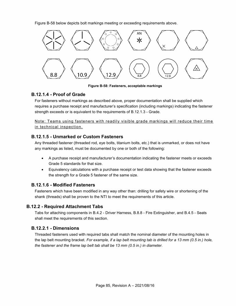
Page 85, Revision A – 2021/08/16
Figure B-58 below depicts bolt markings meeting or exceeding requirements above.
Figure B-58: Fasteners, acceptable markings
B.12.1.4 - Proof of Grade
For fasteners without markings as described above, proper documentation shall be supplied which
requires a purchase receipt and manufacturer’s specification (including markings) indicating the fastener
strength exceeds or is equivalent to the requirements of B.12.1.3 - Grade.
Note: Teams us ing fas teners wi th readi ly v is ib le grade mark ings wi l l reduce their t ime
in technical inspect ion.
B.12.1.5 - Unmarked or Custom Fasteners
Any threaded fastener (threaded rod, eye bolts, titanium bolts, etc.) that is unmarked, or does not have
any markings as listed, must be documented by one or both of the following:
A purchase receipt and manufacturer’s documentation indicating the fastener meets or exceeds
Grade 5 standards for that size.
Equivalency calculations with a purchase receipt or test data showing that the fastener exceeds
the strength for a Grade 5 fastener of the same size.
B.12.1.6 - Modified Fasteners
Fasteners which have been modified in any way other than: drilling for safety wire or shortening of the
shank (threads) shall be proven to the NTI to meet the requirements of this article.
B.12.2 - Required Attachment Tabs
Tabs for attaching components in B.4.2 - Driver Harness, B.8.8 - Fire Extinguisher, and B.4.5 - Seats
shall meet the requirements of this section.
B.12.2.1 - Dimensions
Threaded fasteners used with required tabs shall match the nominal diameter of the mounting holes in
the lap belt mounting bracket. For example, if a lap belt mounting tab is drilled for a 13 mm (0.5 in.) hole,
the fastener and the frame lap belt tab shall be 13 mm (0.5 in.) in diameter.
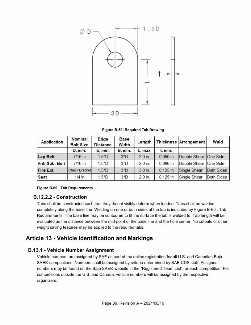
Page 86, Revision A – 2021/08/16
Figure B-59: Required Tab Drawing
Figure B-60 : Tab Requirements
B.12.2.2 - Construction
Tabs shall be constructed such that they do not visibly deform when loaded. Tabs shall be welded
completely along the base line. Welding on one or both sides of the tab is indicated by Figure B-60 : Tab
Requirements. The base line may be contoured to fit the surface the tab is welded to. Tab length will be
evaluated as the distance between the mid-point of the base line and the hole center. No cutouts or other
weight saving features may be applied to the required tabs.
Article 13 - Vehicle Identification and Markings
B.13.1 - Vehicle Number Assignment
Vehicle numbers are assigned by SAE as part of the online registration for all U.S. and Canadian Baja
SAE® competitions. Numbers shall be assigned by criteria determined by SAE CDS staff. Assigned
numbers may be found on the Baja SAE® website in the “Registered Team List” for each competition. For
competitions outside the U.S. and Canada, vehicle numbers will be assigned by the respective
organizers.
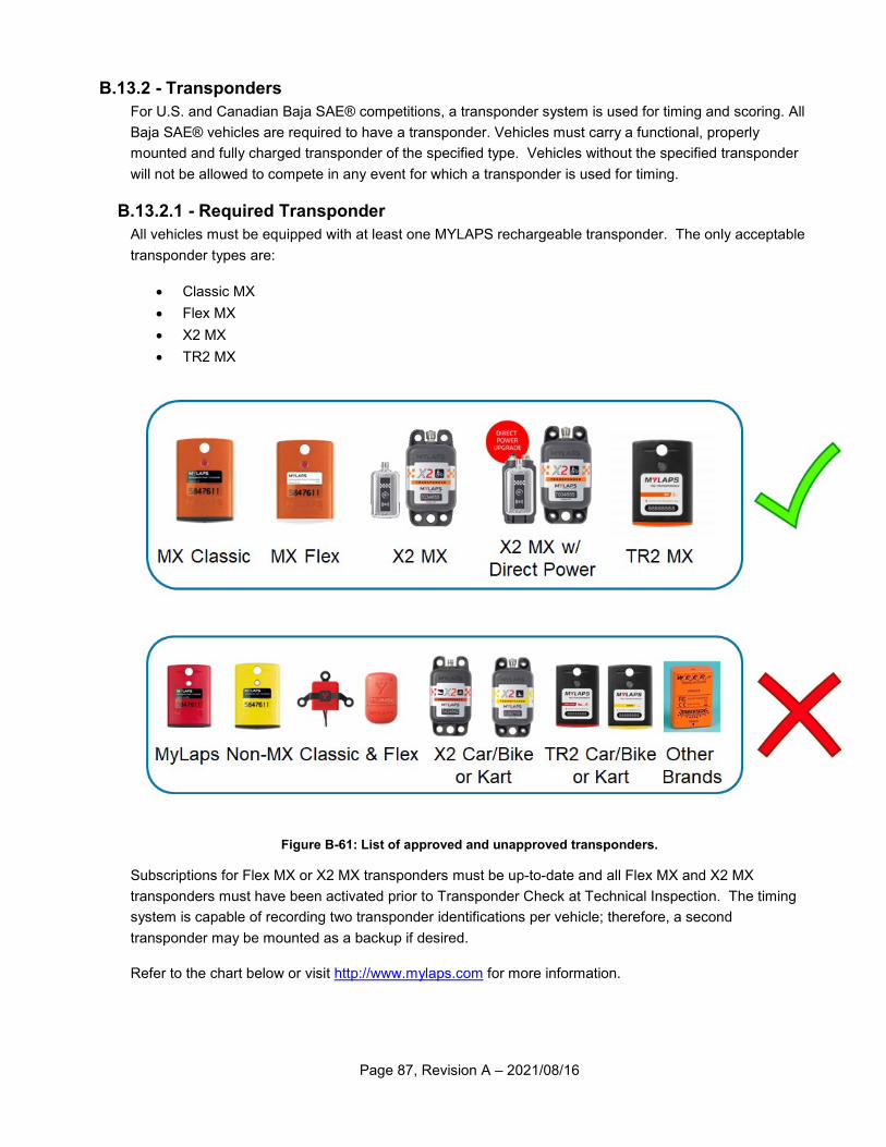
Page 87, Revision A – 2021/08/16
B.13.2 - Transponders
For U.S. and Canadian Baja SAE® competitions, a transponder system is used for timing and scoring. All
Baja SAE® vehicles are required to have a transponder. Vehicles must carry a functional, properly
mounted and fully charged transponder of the specified type. Vehicles without the specified transponder
will not be allowed to compete in any event for which a transponder is used for timing.
B.13.2.1 - Required Transponder
All vehicles must be equipped with at least one MYLAPS rechargeable transponder. The only acceptable
transponder types are:
Classic MX
Flex MX
X2 MX
TR2 MX
Figure B-61: List of approved and unapproved transponders.
Subscriptions for Flex MX or X2 MX transponders must be up-to-date and all Flex MX and X2 MX
transponders must have been activated prior to Transponder Check at Technical Inspection. The timing
system is capable of recording two transponder identifications per vehicle; therefore, a second
transponder may be mounted as a backup if desired.
Refer to the chart below or visit http://www.mylaps.com for more information.
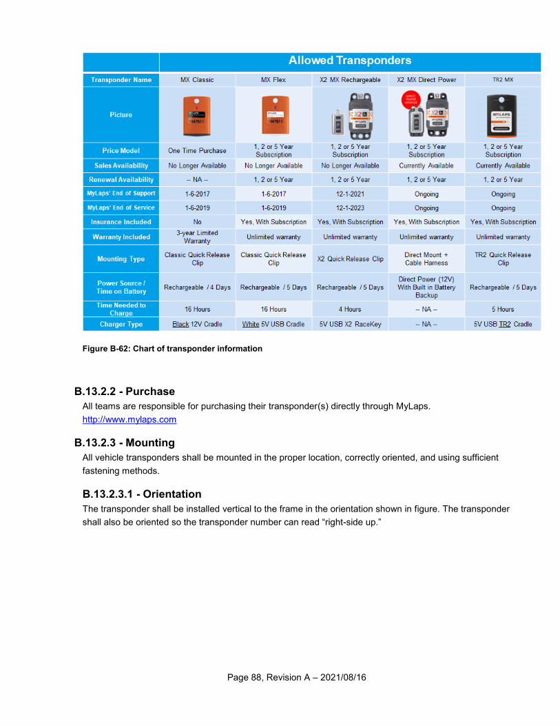
Page 88, Revision A – 2021/08/16
Figure B-62: Chart of transponder information
B.13.2.2 - Purchase
All teams are responsible for purchasing their transponder(s) directly through MyLaps.
http://www.mylaps.com
B.13.2.3 - Mounting
All vehicle transponders shall be mounted in the proper location, correctly oriented, and using sufficient
fastening methods.
B.13.2.3.1 - Orientation
The transponder shall be installed vertical to the frame in the orientation shown in figure. The transponder
shall also be oriented so the transponder number can read “right-side up.”
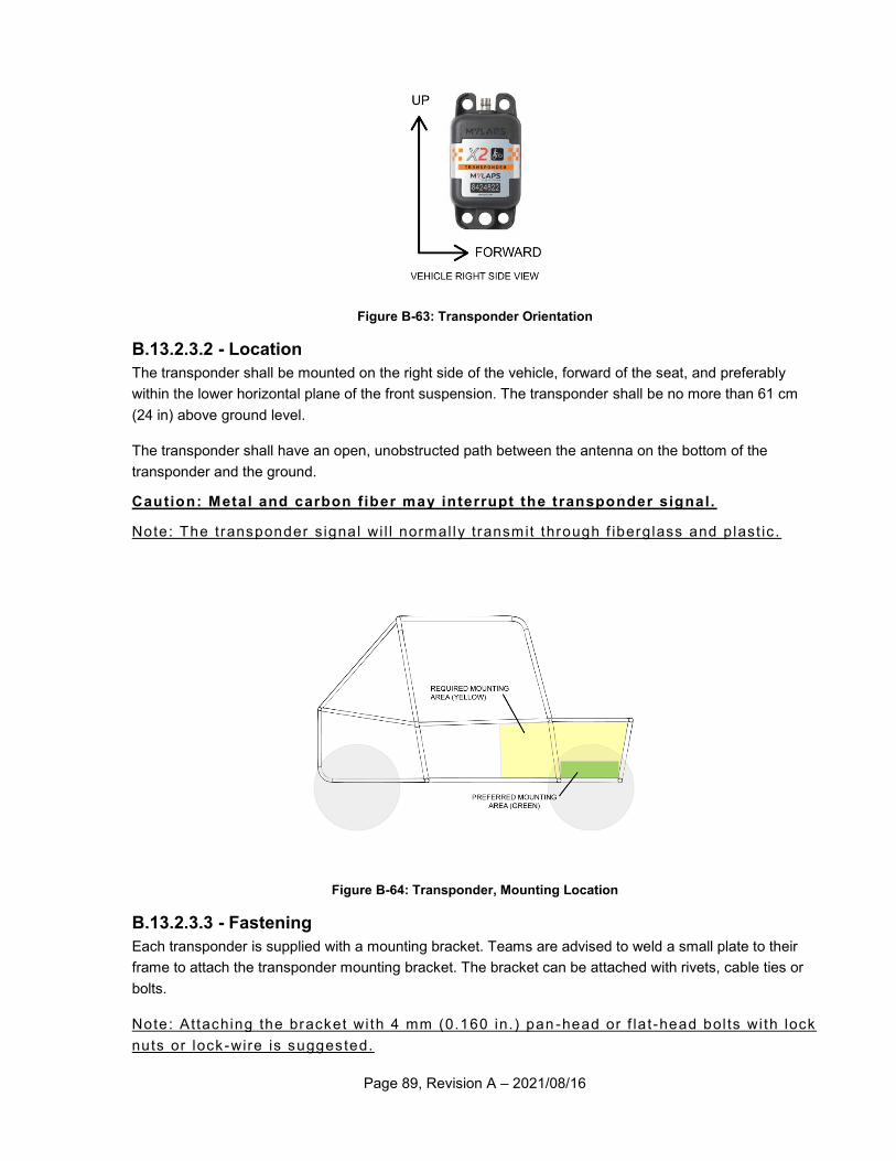
Page 89, Revision A – 2021/08/16
Figure B-63: Transponder Orientation
B.13.2.3.2 - Location
The transponder shall be mounted on the right side of the vehicle, forward of the seat, and preferably
within the lower horizontal plane of the front suspension. The transponder shall be no more than 61 cm
(24 in) above ground level.
The transponder shall have an open, unobstructed path between the antenna on the bottom of the
transponder and the ground.
Caution: Metal and carbon f iber may interrupt the transponder signal.
Note: The transponder s ignal wi l l normal ly transmit through f iberg lass and p last ic .
Figure B-64: Transponder, Mounting Location
B.13.2.3.3 - Fastening
Each transponder is supplied with a mounting bracket. Teams are advised to weld a small plate to their
frame to attach the transponder mounting bracket. The bracket can be attached with rivets, cable ties or
bolts.
Note: Attaching the bracket wi th 4 mm (0.160 in.) pan -head or f la t -head bol ts wi th lock
nuts or lock -wire is suggested.

Page 90, Revision A – 2021/08/16
B.13.2.3.4 - Interference
RF systems transmitting voice and/or data can cause harmful interference with the signal transmitted by
the transponder. Care should be taken when designing, fabricating, or maintaining RF systems near the
transponder.
Note: The transponder equipment operates at a f requency of 3.59 MHz.
B.13.3 - Vehicle Numbers
Vehicle numbers are used by the organizers and officials to positively identify team vehicles. Teams must
design numbers to be visible in all race conditions or keep them clean and conspicuous. Numbers shall
not be obscured by any other portion of the vehicle.
Caution: Numbers that are not easi ly read may be black f lagged and might not be
scored during the endurance event .
B.13.3.1 - Required Numbers
Three primary numbers are required to be securely affixed to the car. The vehicle’s number shall be
readily visible from the left side, right side, and the front of the vehicle and strongly contrast with the
number’s background color.
B.13.3.2 - Required Font
Vehicle numbers shall be displayed in either the “Highway Gothic Regular” font or “Century Gothic Bold”
font. No other fonts are permitted. Examples of both fonts are given below.
Figure B-65 : Approved vehicle number font examples.
B.13.3.3 - Location
B.13.3.3.1 - Side Numbers
Side numbers, mounted to the left and the right sides of the vehicle, shall be mounted above the SIM and
aft of the plane of the RRH. Side numbers shall not be visually obstructed by any part of the vehicle.
B.13.3.3.2 - Front Number
The angle of the plane of the front-facing numbers, when affixed to the vehicle above the SIM, shall be
less than or equal to 45 deg. from vertical.
The angle of the plane of the front numbers, when affixed to the vehicle below the SIM, shall be less than
or equal to 15 deg. from vertical.
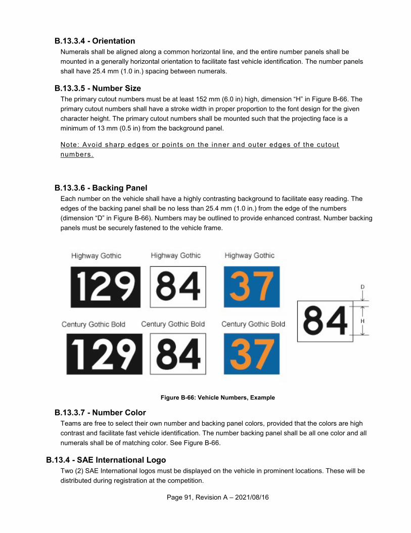
Page 91, Revision A – 2021/08/16
B.13.3.4 - Orientation
Numerals shall be aligned along a common horizontal line, and the entire number panels shall be
mounted in a generally horizontal orientation to facilitate fast vehicle identification. The number panels
shall have 25.4 mm (1.0 in.) spacing between numerals.
B.13.3.5 - Number Size
The primary cutout numbers must be at least 152 mm (6.0 in) high, dimension “H” in Figure B-66. The
primary cutout numbers shall have a stroke width in proper proportion to the font design for the given
character height. The primary cutout numbers shall be mounted such that the projecting face is a
minimum of 13 mm (0.5 in) from the background panel.
Note: Avoid sharp edges or points on the inner and outer edges of the cutout
numbers.
B.13.3.6 - Backing Panel
Each number on the vehicle shall have a highly contrasting background to facilitate easy reading. The
edges of the backing panel shall be no less than 25.4 mm (1.0 in.) from the edge of the numbers
(dimension “D” in Figure B-66). Numbers may be outlined to provide enhanced contrast. Number backing
panels must be securely fastened to the vehicle frame.
Figure B-66: Vehicle Numbers, Example
B.13.3.7 - Number Color
Teams are free to select their own number and backing panel colors, provided that the colors are high
contrast and facilitate fast vehicle identification. The number backing panel shall be all one color and all
numerals shall be of matching color. See Figure B-66.
B.13.4 - SAE International Logo
Two (2) SAE International logos must be displayed on the vehicle in prominent locations. These will be
distributed during registration at the competition.
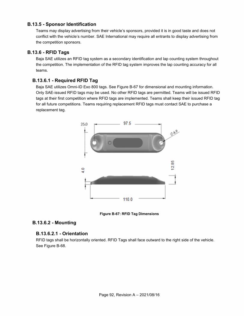
Page 92, Revision A – 2021/08/16
B.13.5 - Sponsor Identification
Teams may display advertising from their vehicle’s sponsors, provided it is in good taste and does not
conflict with the vehicle’s number. SAE International may require all entrants to display advertising from
the competition sponsors.
B.13.6 - RFID Tags
Baja SAE utilizes an RFID tag system as a secondary identification and lap counting system throughout
the competition. The implementation of the RFID tag system improves the lap counting accuracy for all
teams.
B.13.6.1 - Required RFID Tag
Baja SAE utilizes Omni-ID Exo 800 tags. See Figure B-67 for dimensional and mounting information.
Only SAE-issued RFID tags may be used. No other RFID tags are permitted. Teams will be issued RFID
tags at their first competition where RFID tags are implemented. Teams shall keep their issued RFID tag
for all future competitions. Teams requiring replacement RFID tags must contact SAE to purchase a
replacement tag.
Figure B-67: RFID Tag Dimensions
B.13.6.2 - Mounting
B.13.6.2.1 - Orientation
RFID tags shall be horizontally oriented. RFID Tags shall face outward to the right side of the vehicle.
See Figure B-68.
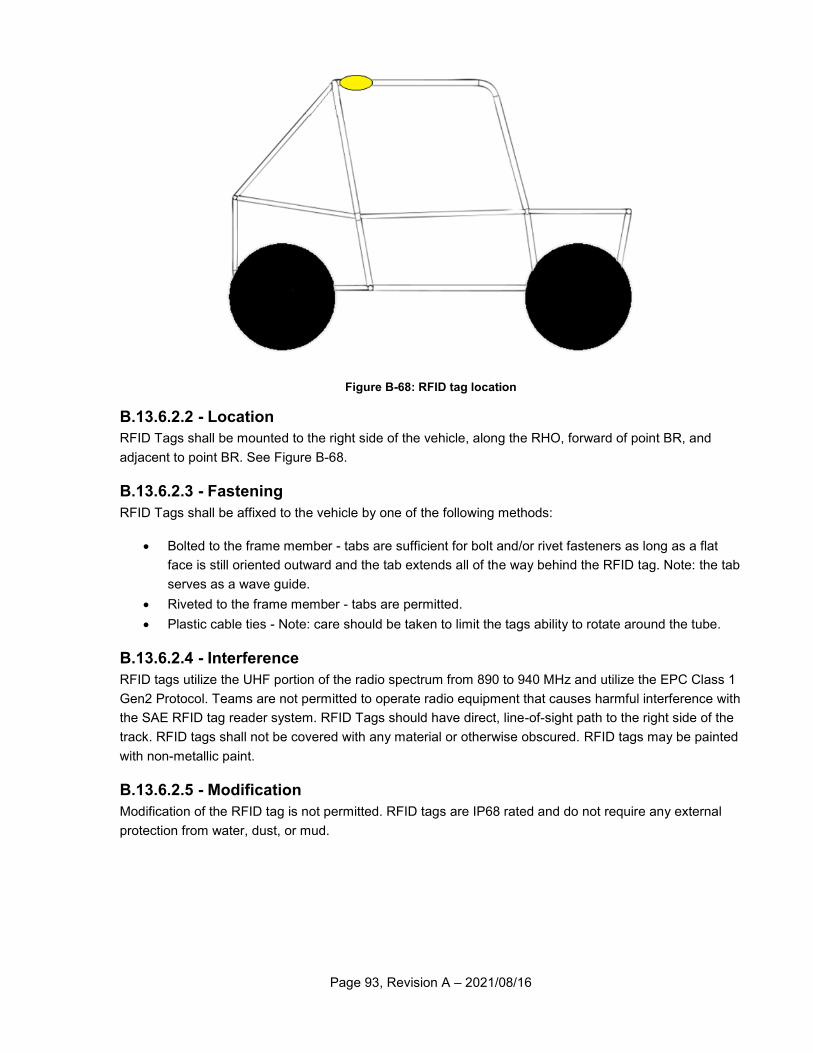
Page 93, Revision A – 2021/08/16
Figure B-68: RFID tag location
B.13.6.2.2 - Location
RFID Tags shall be mounted to the right side of the vehicle, along the RHO, forward of point BR, and
adjacent to point BR. See Figure B-68.
B.13.6.2.3 - Fastening
RFID Tags shall be affixed to the vehicle by one of the following methods:
Bolted to the frame member - tabs are sufficient for bolt and/or rivet fasteners as long as a flat
face is still oriented outward and the tab extends all of the way behind the RFID tag. Note: the tab
serves as a wave guide.
Riveted to the frame member - tabs are permitted.
Plastic cable ties - Note: care should be taken to limit the tags ability to rotate around the tube.
B.13.6.2.4 - Interference
RFID tags utilize the UHF portion of the radio spectrum from 890 to 940 MHz and utilize the EPC Class 1
Gen2 Protocol. Teams are not permitted to operate radio equipment that causes harmful interference with
the SAE RFID tag reader system. RFID Tags should have direct, line-of-sight path to the right side of the
track. RFID tags shall not be covered with any material or otherwise obscured. RFID tags may be painted
with non-metallic paint.
B.13.6.2.5 - Modification
Modification of the RFID tag is not permitted. RFID tags are IP68 rated and do not require any external
protection from water, dust, or mud.
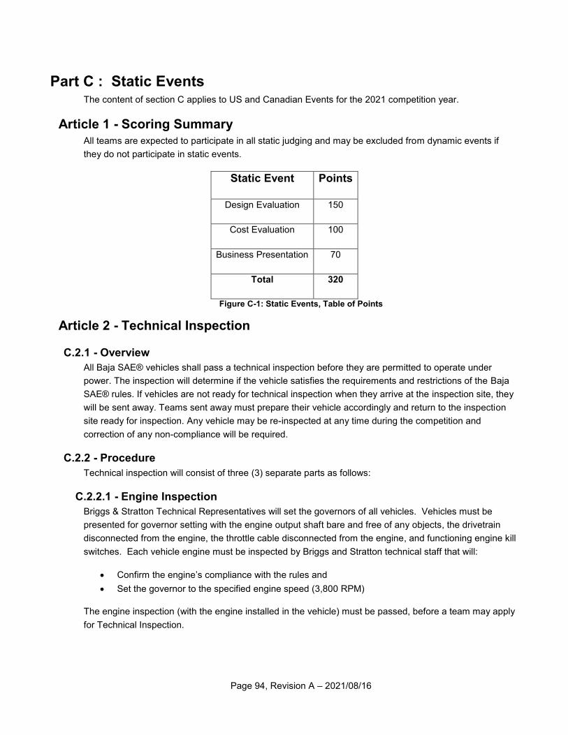
Page 94, Revision A – 2021/08/16
Part C : Static Events The content of section C applies to US and Canadian Events for the 2021 competition year.
Article 1 - Scoring Summary
All teams are expected to participate in all static judging and may be excluded from dynamic events if
they do not participate in static events.
Static Event Points
Design Evaluation 150
Cost Evaluation 100
Business Presentation 70
Total 320
Figure C-1: Static Events, Table of Points
Article 2 - Technical Inspection
C.2.1 - Overview
All Baja SAE® vehicles shall pass a technical inspection before they are permitted to operate under
power. The inspection will determine if the vehicle satisfies the requirements and restrictions of the Baja
SAE® rules. If vehicles are not ready for technical inspection when they arrive at the inspection site, they
will be sent away. Teams sent away must prepare their vehicle accordingly and return to the inspection
site ready for inspection. Any vehicle may be re-inspected at any time during the competition and
correction of any non-compliance will be required.
C.2.2 - Procedure
Technical inspection will consist of three (3) separate parts as follows:
C.2.2.1 - Engine Inspection
Briggs & Stratton Technical Representatives will set the governors of all vehicles. Vehicles must be
presented for governor setting with the engine output shaft bare and free of any objects, the drivetrain
disconnected from the engine, the throttle cable disconnected from the engine, and functioning engine kill
switches. Each vehicle engine must be inspected by Briggs and Stratton technical staff that will:
Confirm the engine’s compliance with the rules and
Set the governor to the specified engine speed (3,800 RPM)
The engine inspection (with the engine installed in the vehicle) must be passed, before a team may apply
for Technical Inspection.
Page 95, Revision A – 2021/08/16
C.2.2.2 - Technical Inspection
Each vehicle will be inspected to determine if it complies with the requirements and restrictions of the
Baja SAE® rules. Each team must bring the following items to inspection:
Frame Material Documentation: Receipts documenting the materials purchased, or otherwise
acquired, and used to build the frame.
Roll Cage Specification Sheet: A signed and completed copy of the Roll Cage Specification Sheet
Technical Inspection Sheet: A properly completed Technical Inspection Sheet, see
www.bajasae.net/go/downloads
Drivetrain Check Sheet: A properly completed Drivetrain Check Sheet
Drivers Present: All drivers must be present at technical inspection.
The Technical Inspection must be passed before a team may apply for Dynamic Brake Check.
C.2.2.3 - Dynamic Brake Check
At Dynamic Brake Check, both the external and cockpit kill switches will be tested for functionality before
the vehicle is allowed to proceed. If both switches pass the test, then the vehicle will be dynamically
brake tested. Each vehicle must demonstrate its ability to lock all four wheels and come to rest in an
approximately straight line after acceleration run specified by the inspectors. If a vehicle fails to pass any
part of the inspection, it must be corrected and brought into compliance with the rules before the vehicle
is permitted to operate.
C.2.3 - Preparation
Teams presenting Technical Inspection Sheets that are incomplete, inaccurate (i.e. do not correspond to
the actual condition of the vehicle), are found to have four (4) or more items not in accordance with the
rules, or do not represent a serious effort at pre-inspection will be denied inspection at that time and sent
back to the end of the inspection line.
C.2.4 - Technical Inspection Sheet
C.2.4.1 - Pre Inspection Requirements
Before bringing their vehicle to technical inspection each team must
Pre-inspect the vehicle for compliance with the rules
Complete the official technical inspection sheet (available at www.bajasae.net/go/downloads)
Have the completed inspection list signed by the faculty advisor and team captain. Required
reading includes for news and important information includes: www.bajasae.net/go/news.
C.2.4.2 - Inspection Sheet Version
Teams must download the most current version of the technical inspection sheet within two weeks of the
competition and thoroughly inspect their vehicle in accordance with the technical inspection sheet.
C.2.5 - Inspection Stickers
A multi-part inspection sticker will be issued in sections to each vehicle as each of the three parts of
technical inspection is completed .The inspectors will place the inspection sticker on the right side of the
firewall above the driver’s shoulder. The inspection sticker must remain on the vehicle throughout the
competition. Vehicles without all parts of the inspection sticker may not be operated under power.
Page 96, Revision A – 2021/08/16
Any or all parts of the inspection sticker may be removed from any vehicle by the NTI that has been
damaged or which is reasonably believed may not comply with the rules.
C.2.6 - As Approved Condition
C.2.6.1 - Modifications
Once a vehicle has passed technical inspection its configuration may not be modified. All accessory
components such as roofs, wings, bumpers, etc. are considered part of the configuration and must
remain on the vehicle at all times.
C.2.6.2 - Repairs
Approved vehicles must remain in “as-approved” condition throughout the competition. Any repairs of a
part that is not identical as the broken part must be approved prior to the repair.
C.2.6.3 - Non-Matching Components
Non-identical parts not approved will be subject to an appropriate performance penalty.
C.2.6.4 - Tuning
Minor adjustments permitted by the rules and normal vehicle maintenance and tuning are not considered
modifications.
Article 3 - Design Evaluation
C.3.1 - Objective
The objective of the engineering design evaluation event is to evaluate the engineering effort that went
into the design of the vehicle and how the engineering meets the intent of the market, as detailed in the
A.1.3 - Baja SAE Program Objective and the A.1.4 - Design Subject. Students will be judged on the
creation of design requirements and the ability to meet those requirements, computer aided drafting,
analysis, testing and development, manufacturability, serviceability, system integration and how the
vehicle works together as a whole. Each of these parts of the engineering product development cycle will
be judged within the following subsystems: Suspension, Steering, Brakes, Drivetrain/Powertrain,
4WD/AWD, and Chassis and Ergonomics.
The vehicle that illustrates the best use of engineering to meet the design goals and the best
understanding of the design by the team members will win the design event.
Teams are reminded that Baja SAE® is an engineering design competition and that in the Engineering
Design Event, teams are evaluated on their design. Components and systems that are incorporated into
the design as finished items are not evaluated as a student designed unit, but are only assessed on the
team’s selection and application of that unit. For example, teams that design and fabricate their own
shocks are evaluated on the shock design itself as well as the shock’s application within the suspension
system. Teams using commercially available shocks are evaluated only on selection and application
within the suspension system.
C.3.2 - Metrics
The engineering design event student guide and score sheet can be found at
www.bajasae.net/go/downloads.
Page 97, Revision A – 2021/08/16
The engineering design event consists of two parts: Design Evaluation and a Design Review Briefing
(DRB) that will be used as a part of the design evaluation.
C.3.3 - Design Documents
C.3.3.1 - Overview
The design evaluation judging will start with submission, before the event, of a Design Review Briefing
(DRB). The DRB will be reviewed by the design judges who will ultimately judge the team and vehicle
during the Design Evaluation Event.
C.3.3.2 - Document Submittal
The DRB must be submitted electronically in Adobe Acrobat Format (PDF). The document must be a
single file (text, drawings and optional content are all inclusive). The maximum size for the file is 25 MB.
C.3.3.3 - Format
The DRB template must be followed and the template can be found on the BajaSAE.net website.
C.3.4 - Design Evaluation
The design judges will evaluate the engineering effort based upon the team’s DRB, the design
presentation, responses to questions, and an inspection of the vehicle (if applicable).
C.3.4.1 - Design Score Sheet
The Design Judging Score Sheet is available at www.bajasae.net/go/downloads. The judges strongly
urge all teams to read and study the score sheet and all other documents related to design judging that
are available on the website.
C.3.4.2 - Support Material (Onsite Events)
Teams are encouraged to bring with them to Design Evaluation any photographs, drawings, plans, charts,
example components, or other materials that they believe are needed to support the presentation of the
vehicle and the discussion of their development process. Use of laptop or notebook computers, posters,
and binders is highly encouraged, but projectors may not be used. The burden of proof is on the students
and the design score will reflect not only the student’s ability to properly articulate and communicate their
engineering effort, but must also be backed up by sufficient documentation.
C.3.4.3 - Judging Format
The actual format of Design Evaluation may change from year to year as determined by the organizing
body and can be found at www.bajasae.net/go/downloads.
Design Evaluation is typically organized as follows:
Initial judging of all vehicles
Final judging ranking the top 3 to 10 vehicles.
C.3.4.4 - Design Finals
C.3.4.4.1 - Overview
The purpose of Design Finals is to reward and call attention to those vehicles judged to have the best
engineering designs. Design Finals are held after the conclusion of Design Evaluation so that the finalists
Page 98, Revision A – 2021/08/16
may be chosen, and then judged as described in section C.3.4.4.2 - Presentation Format. The number of
finalists may vary from as few as three to as many as ten, as determined by the number of entries and the
results of Design Evaluation.
C.3.4.4.2 - Presentation Format
The Design Finals format and timing may change from year to year as determined by the organizing
body. The Design Finals format, timing, and instructions will be released in a General Notice posted on
the BajaSAE.net website. One or more team members may give the presentation to the judges. Any team
member on the presentation floor may answer the questions from the judges even if that member did not
speak during the presentation. For onsite events, it is recommended teams bring a laptop computer,
binders, or posters to communicate their design work. No projectors will be allowed.
C.3.5 - Design Comparison Requirement
Teams with vehicles that finished in a top ten position overall in any of the previous year’s Baja SAE®
competitions are classified as having created a “successful design.” Teams that created such successful
vehicles are required to provide a comparison, using the template described below, of their current design
with their previous year’s design, even if the current design is entirely new. Teams shall be prepared to
present their design comparison when requested by the design judges. If the judges find that the design
changes are not significant, not supported by a detailed analysis, or not been sufficiently documented,
then a penalty of up to 150 points may be assessed against the design score.
C.3.5.1 - Redesign Comparison Document
The design comparison report must follow the template found at www.bajasae.net/go/downloads and
should be submitted by way of the instructions in the template file.
The documentation should be a year to year comparison of the major structure and/or systems of the
vehicle and may consist of any, or all, of the following, supported by appropriate captions:
1) Plans
2) Drawings
3) Photographs
Design changes to correct failures of the previous design should be accompanied by a thorough analysis
of why the failure occurred and the theoretical data supporting the new design, etc.
C.3.6 - Scoring
The engineering design event will be worth 150 points.
The judges may at their discretion award the highest placing team less than the maximum noted above.
Design finalist may also receive bonus points that could make their scores higher than the maximum
noted above.
Page 99, Revision A – 2021/08/16
Article 4 - Cost Evaluation
C.4.1 - Objective
The purpose of the Cost Event is to provide teams an opportunity to show the cost/benefit design
decisions used in the prototype vehicle. The Cost Event aims to represent a comparable model for each
team to be measured against. Revisions in the Cost Event implemented for the 2018 Competition
Season are an effort to streamline the costing and evaluation processes and provide a more comparable
and fair costing model.
For up-to-date information on the Cost Event, please refer
to http:/ /www.bajasae.net /go/cost and check back through the fall as this
information is updated.
C.4.2 - Cost Report
The Cost Report will be summarized in an online format where teams can complete their overall BOM (Bill
of Materials) with material and manufacturing costs.
C.4.2.1 - Costing Sheets
The core of the report is the series of costing sheets. Implemented in 2018, the format of these sheets will
follow the online format. See ht tp:/ /www.bajasae.net/go/cost for descriptions of these sheets and
the instructions on how to use them.
C.4.2.2 - Cost Documentation
Cost Documentation is required for all purchased components and material costs. Implemented in 2018,
this documentation will come from a common database of material and component costs. These items
may be specific or may be generalized into a cost category of material/components. If a team’s
purchased material/components are not in the common database, the team may submit an “Add Item
Request” for their specific material or component for approval. Once submitted and approved, that
material is available for all teams to use. See ht tp:/ /www.bajasae.net/go/cost for more detail on
this database and how to use it in the Costing Sheets.
C.4.2.3 - Cost Report Submission
Teams must submit a cost report at the cost report deadline. This report must be as complete as possible
at this deadline. It will be compared to the cost adjustment report submitted prior to each competition. If
there is a difference in the prototype cost of more than 20% plus or minus, there will be a twenty-five (25)
point penalty assessed to the team in the cost event. If the prototype cost report changes more than 40%
plus or minus, the cost report will be deemed incomplete and team will be excluded from the prototype
cost competition and will receive zero (0) points for the cost competition.
C.4.2.4 - Cost Reduction Report
Teams must submit a report with up to two (2) ideas for cost reduction. Each idea will be worth up to 10
points. The format of the report and the scoring matrix will be posted at http://www.bajasae.net/.
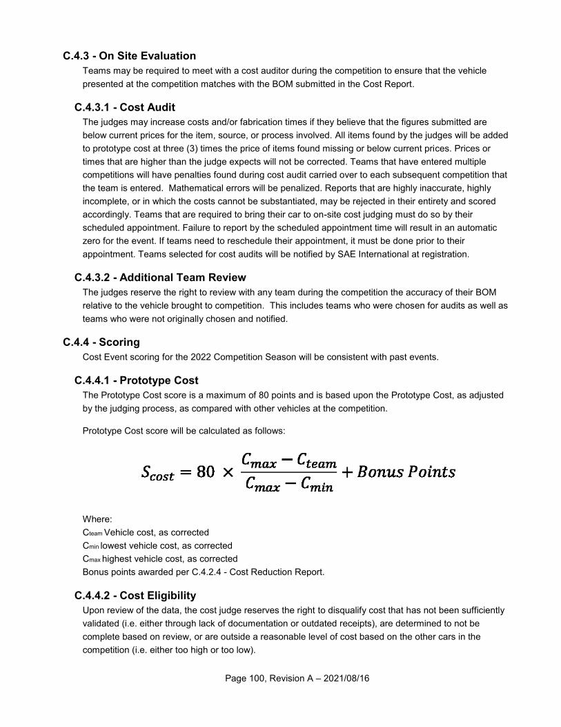
Page 100, Revision A – 2021/08/16
C.4.3 - On Site Evaluation
Teams may be required to meet with a cost auditor during the competition to ensure that the vehicle
presented at the competition matches with the BOM submitted in the Cost Report.
C.4.3.1 - Cost Audit
The judges may increase costs and/or fabrication times if they believe that the figures submitted are
below current prices for the item, source, or process involved. All items found by the judges will be added
to prototype cost at three (3) times the price of items found missing or below current prices. Prices or
times that are higher than the judge expects will not be corrected. Teams that have entered multiple
competitions will have penalties found during cost audit carried over to each subsequent competition that
the team is entered. Mathematical errors will be penalized. Reports that are highly inaccurate, highly
incomplete, or in which the costs cannot be substantiated, may be rejected in their entirety and scored
accordingly. Teams that are required to bring their car to on-site cost judging must do so by their
scheduled appointment. Failure to report by the scheduled appointment time will result in an automatic
zero for the event. If teams need to reschedule their appointment, it must be done prior to their
appointment. Teams selected for cost audits will be notified by SAE International at registration.
C.4.3.2 - Additional Team Review
The judges reserve the right to review with any team during the competition the accuracy of their BOM
relative to the vehicle brought to competition. This includes teams who were chosen for audits as well as
teams who were not originally chosen and notified.
C.4.4 - Scoring
Cost Event scoring for the 2022 Competition Season will be consistent with past events.
C.4.4.1 - Prototype Cost
The Prototype Cost score is a maximum of 80 points and is based upon the Prototype Cost, as adjusted
by the judging process, as compared with other vehicles at the competition.
Prototype Cost score will be calculated as follows:
Where:
Cteam Vehicle cost, as corrected
Cmin lowest vehicle cost, as corrected
Cmax highest vehicle cost, as corrected
Bonus points awarded per C.4.2.4 - Cost Reduction Report.
C.4.4.2 - Cost Eligibility
Upon review of the data, the cost judge reserves the right to disqualify cost that has not been sufficiently
validated (i.e. either through lack of documentation or outdated receipts), are determined to not be
complete based on review, or are outside a reasonable level of cost based on the other cars in the
competition (i.e. either too high or too low).
Page 101, Revision A – 2021/08/16
Article 5 - Business Presentation (BP)
C.5.1 - Objective
The Business Presentation event evaluates the team’s ability to develop and deliver a comprehensive
business, logistical, production, or technical case that will convince outside interests to invest in the
team’s concept.
C.5.2 - Concept
Concept information will be available on the Baja SAE website. BP concepts may change for each
competition. The content of a team’s BP shall match the requirements of the concept. The team’s BP
shall relate specifically to the vehicle as entered for the specific competition. Teams should assume that
the judges represent different areas, including engineering, production, marketing, and finance. Teams
should assume that not all judges may be engineers. The BP location and setting will be communicated
on the Baja SAE website.
C.5.3 - Tardiness
Teams that fail to make their presentation during the assigned time period will receive zero points for the
BP event.
C.5.4 - Submissions
The BP concept may require information to be submitted prior to the event. Specific details will be
included in the BP concept information on the Baja SAE website. Submissions may be graded as part of
the BP event score. Pre-event submissions will be subject to penalties as described in A.6.2.7 - Failure to
Meet Deadlines.
C.5.5 - Format
BP will operate in a hybrid model consisting of virtual and onsite presentations.
One or more team members will present the BP to the judges. All team members who will give any part of
the presentation, or will respond to the judges’ questions shall be in the local presentation area at the time
the presentation starts, and shall be introduced and identified to the judges. BP’s will be time limited, and
judges will stop any presentation exceeding the time limit. Judges will not interrupt the BP for questions.
Any questions will only be asked by the judges immediately following the presentation.
C.5.5.1 - Virtual Presentations
All teams will virtually present their BP to a panel of judges and their score will apply to all onsite
competitions they are attending. Teams will be ranked only against teams attending the same
competition. The software platform for virtual presentations will be defined and communicated by the
organizing body. The virtual presentations will take place before any onsite events. Student teams may
be required to submit a judge pre-read document ahead of their presentation. If so, teams will be notified
ahead of time on the deadline and format.
C.5.5.2 - Onsite Presentations
Based on Virtual Presentation scores, the top scoring BP teams for each onsite competition will then
present to a live judge panel in-person at the respective event. Teams will be notified if they are finalists
approximately 10 days before the in-person competition. The onsite presentations are expected to
contain essentially the same content as the virtual presentation and may be public for other teams to
Page 102, Revision A – 2021/08/16
observe. Teams are allowed to bring with them handouts or other materials that they believe are needed
to support the presentation. The number of teams to present live will be a minimum of 8 teams.
Example for how team rankings might change based on competition attendance:
Team X is going to the multiple competitions. For the first competition, the teams ranked in the top 10
against other teams attending that same competition and thus will present live. For the second
competition, they did not rank in the top 10 and thus will not present live. Just because the team is top 10
in one competition, does not mean they are top 10 in all competitions due to different teams attending
different events.
C.5.6 - Equipment
Any and all audio-visual and/or communication equipment required for a team’s presentation shall be
arranged and provided for by the presenting team.
C.5.7 - Evaluation Criteria
Presentations will be evaluated on content, organization, visual aids, delivery, and the team’s response to
the judges’ questions. The actual quality of the prototype itself will not be considered as part of the
presentation judging. Further information is available on the Baja SAE website.
C.5.8 - Scoring
The BP event is worth 70 points. At the judge’s discretion, the highest placing team may receive less than
the maximum score noted above.
C.5.8.1 - Bonus
In-person BP finals will take place at each onsite event for the top teams to potentially earn bonus points
based on their performance. BP finalists may receive up to 7 bonus points that may make their scores
higher than the maximum noted above.
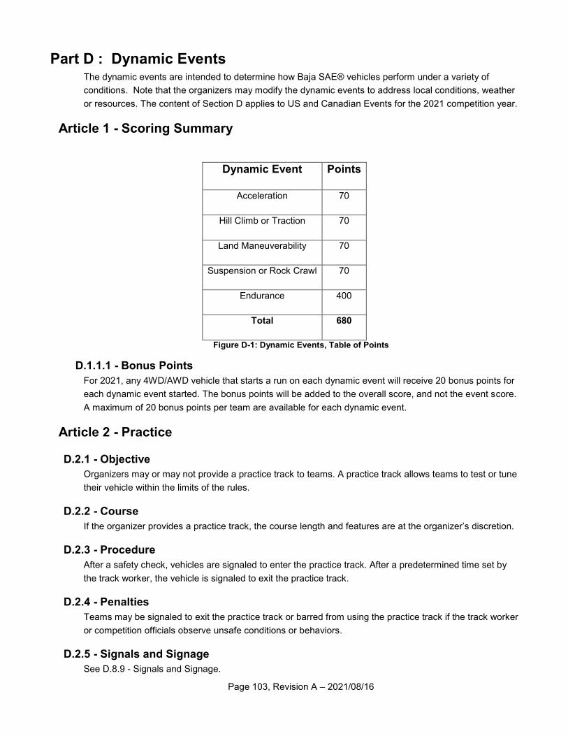
Page 103, Revision A – 2021/08/16
Part D : Dynamic Events The dynamic events are intended to determine how Baja SAE® vehicles perform under a variety of
conditions. Note that the organizers may modify the dynamic events to address local conditions, weather
or resources. The content of Section D applies to US and Canadian Events for the 2021 competition year.
Article 1 - Scoring Summary
Dynamic Event Points
Acceleration 70
Hill Climb or Traction 70
Land Maneuverability 70
Suspension or Rock Crawl 70
Endurance 400
Total 680
Figure D-1: Dynamic Events, Table of Points
D.1.1.1 - Bonus Points
For 2021, any 4WD/AWD vehicle that starts a run on each dynamic event will receive 20 bonus points for
each dynamic event started. The bonus points will be added to the overall score, and not the event score.
A maximum of 20 bonus points per team are available for each dynamic event.
Article 2 - Practice
D.2.1 - Objective
Organizers may or may not provide a practice track to teams. A practice track allows teams to test or tune
their vehicle within the limits of the rules.
D.2.2 - Course
If the organizer provides a practice track, the course length and features are at the organizer’s discretion.
D.2.3 - Procedure
After a safety check, vehicles are signaled to enter the practice track. After a predetermined time set by
the track worker, the vehicle is signaled to exit the practice track.
D.2.4 - Penalties
Teams may be signaled to exit the practice track or barred from using the practice track if the track worker
or competition officials observe unsafe conditions or behaviors.
D.2.5 - Signals and Signage
See D.8.9 - Signals and Signage.
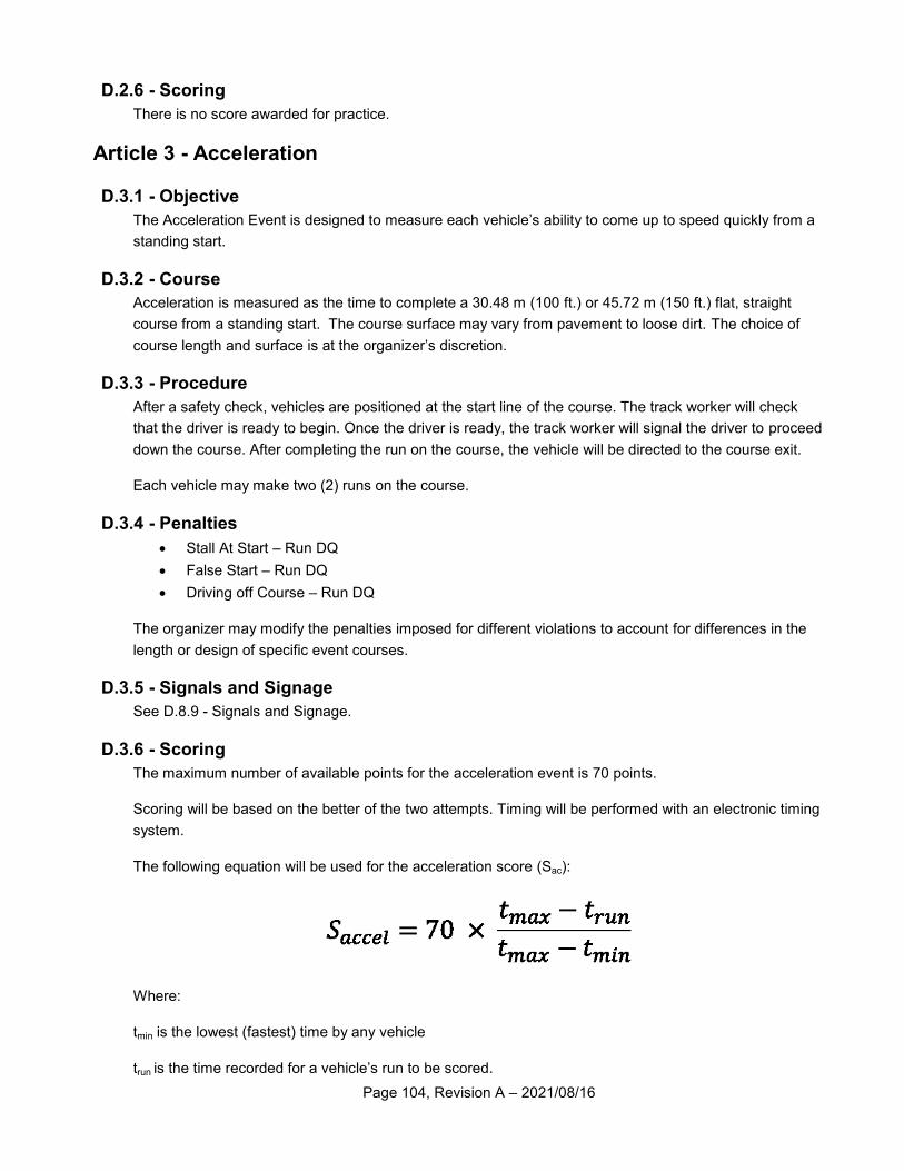
Page 104, Revision A – 2021/08/16
D.2.6 - Scoring
There is no score awarded for practice.
Article 3 - Acceleration
D.3.1 - Objective
The Acceleration Event is designed to measure each vehicle’s ability to come up to speed quickly from a
standing start.
D.3.2 - Course
Acceleration is measured as the time to complete a 30.48 m (100 ft.) or 45.72 m (150 ft.) flat, straight
course from a standing start. The course surface may vary from pavement to loose dirt. The choice of
course length and surface is at the organizer’s discretion.
D.3.3 - Procedure
After a safety check, vehicles are positioned at the start line of the course. The track worker will check
that the driver is ready to begin. Once the driver is ready, the track worker will signal the driver to proceed
down the course. After completing the run on the course, the vehicle will be directed to the course exit.
Each vehicle may make two (2) runs on the course.
D.3.4 - Penalties
Stall At Start – Run DQ
False Start – Run DQ
Driving off Course – Run DQ
The organizer may modify the penalties imposed for different violations to account for differences in the
length or design of specific event courses.
D.3.5 - Signals and Signage
See D.8.9 - Signals and Signage.
D.3.6 - Scoring
The maximum number of available points for the acceleration event is 70 points.
Scoring will be based on the better of the two attempts. Timing will be performed with an electronic timing
system.
The following equation will be used for the acceleration score (Sac):
Where:
tmin is the lowest (fastest) time by any vehicle
trun is the time recorded for a vehicle’s run to be scored.
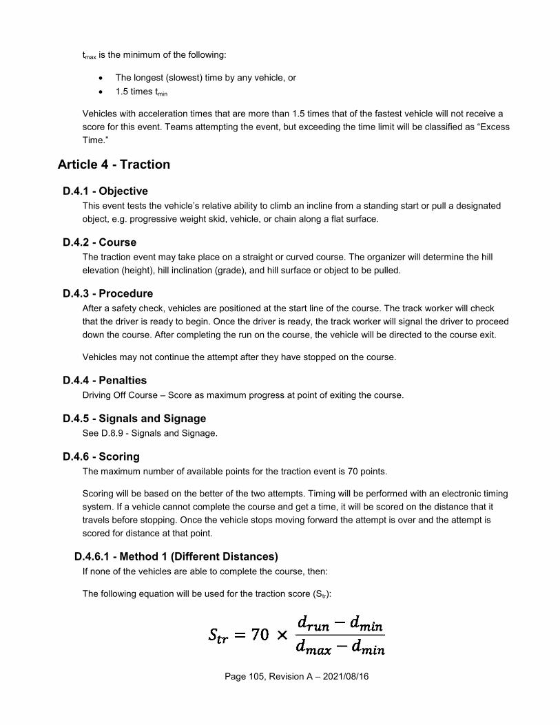
Page 105, Revision A – 2021/08/16
tmax is the minimum of the following:
The longest (slowest) time by any vehicle, or
1.5 times tmin
Vehicles with acceleration times that are more than 1.5 times that of the fastest vehicle will not receive a
score for this event. Teams attempting the event, but exceeding the time limit will be classified as “Excess
Time.”
Article 4 - Traction
D.4.1 - Objective
This event tests the vehicle’s relative ability to climb an incline from a standing start or pull a designated
object, e.g. progressive weight skid, vehicle, or chain along a flat surface.
D.4.2 - Course
The traction event may take place on a straight or curved course. The organizer will determine the hill
elevation (height), hill inclination (grade), and hill surface or object to be pulled.
D.4.3 - Procedure
After a safety check, vehicles are positioned at the start line of the course. The track worker will check
that the driver is ready to begin. Once the driver is ready, the track worker will signal the driver to proceed
down the course. After completing the run on the course, the vehicle will be directed to the course exit.
Vehicles may not continue the attempt after they have stopped on the course.
D.4.4 - Penalties
Driving Off Course – Score as maximum progress at point of exiting the course.
D.4.5 - Signals and Signage
See D.8.9 - Signals and Signage.
D.4.6 - Scoring
The maximum number of available points for the traction event is 70 points.
Scoring will be based on the better of the two attempts. Timing will be performed with an electronic timing
system. If a vehicle cannot complete the course and get a time, it will be scored on the distance that it
travels before stopping. Once the vehicle stops moving forward the attempt is over and the attempt is
scored for distance at that point.
D.4.6.1 - Method 1 (Different Distances)
If none of the vehicles are able to complete the course, then:
The following equation will be used for the traction score (Str):
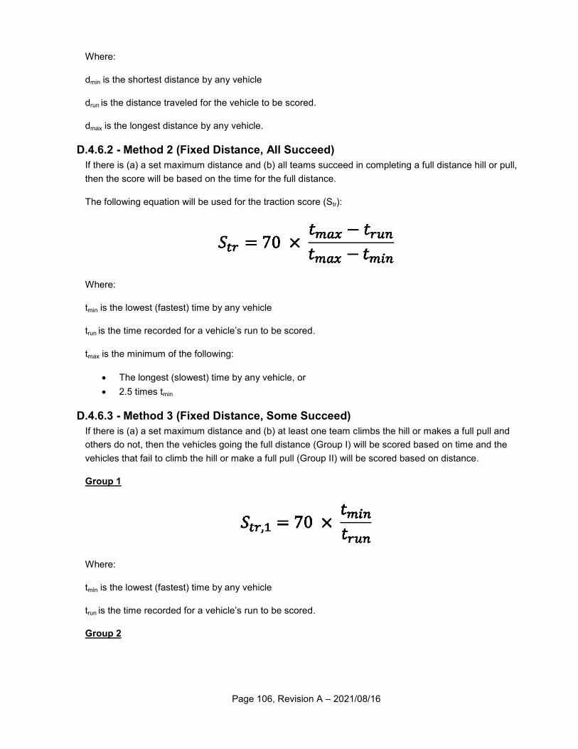
Page 106, Revision A – 2021/08/16
Where:
dmin is the shortest distance by any vehicle
drun is the distance traveled for the vehicle to be scored.
dmax is the longest distance by any vehicle.
D.4.6.2 - Method 2 (Fixed Distance, All Succeed)
If there is (a) a set maximum distance and (b) all teams succeed in completing a full distance hill or pull,
then the score will be based on the time for the full distance.
The following equation will be used for the traction score (Str):
Where:
tmin is the lowest (fastest) time by any vehicle
trun is the time recorded for a vehicle’s run to be scored.
tmax is the minimum of the following:
The longest (slowest) time by any vehicle, or
2.5 times tmin
D.4.6.3 - Method 3 (Fixed Distance, Some Succeed)
If there is (a) a set maximum distance and (b) at least one team climbs the hill or makes a full pull and
others do not, then the vehicles going the full distance (Group I) will be scored based on time and the
vehicles that fail to climb the hill or make a full pull (Group II) will be scored based on distance.
Group 1
Where:
tmin is the lowest (fastest) time by any vehicle
trun is the time recorded for a vehicle’s run to be scored.
Group 2
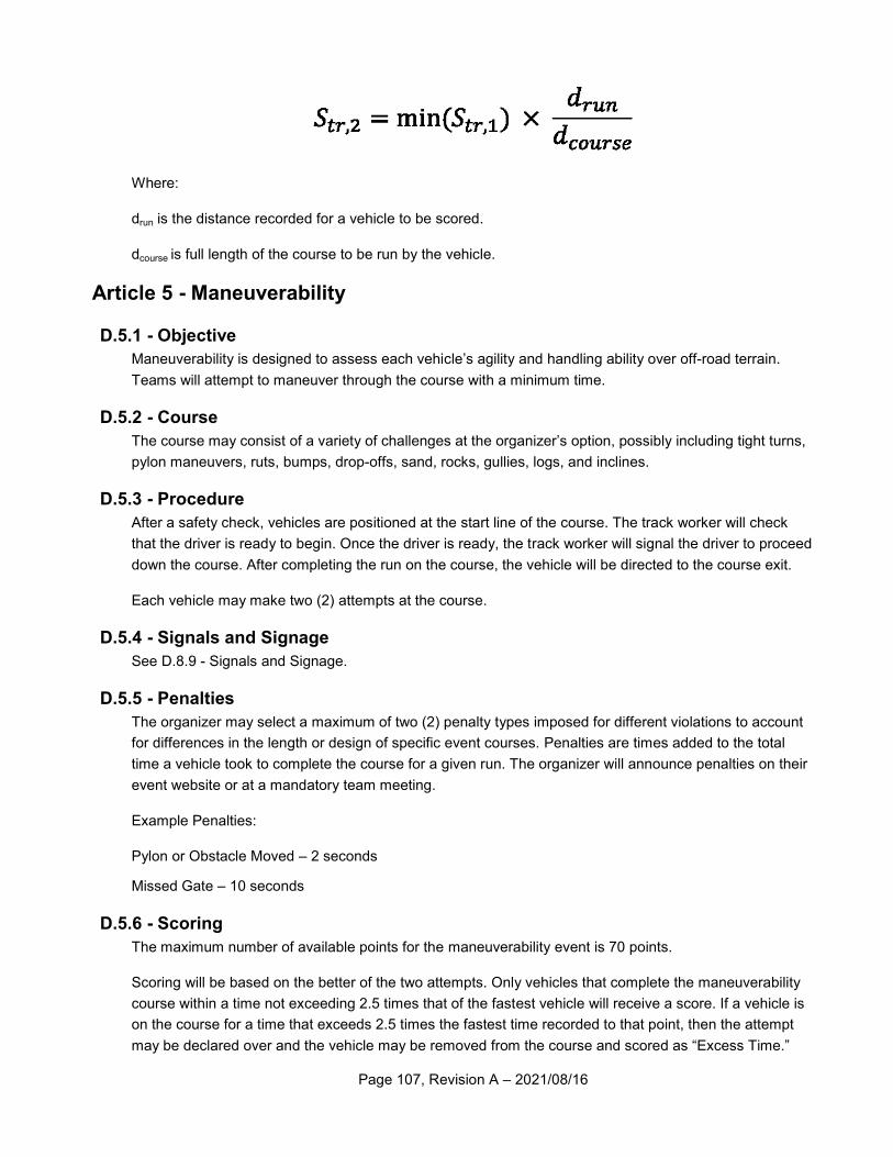
Page 107, Revision A – 2021/08/16
Where:
drun is the distance recorded for a vehicle to be scored.
dcourse is full length of the course to be run by the vehicle.
Article 5 - Maneuverability
D.5.1 - Objective
Maneuverability is designed to assess each vehicle’s agility and handling ability over off-road terrain.
Teams will attempt to maneuver through the course with a minimum time.
D.5.2 - Course
The course may consist of a variety of challenges at the organizer’s option, possibly including tight turns,
pylon maneuvers, ruts, bumps, drop-offs, sand, rocks, gullies, logs, and inclines.
D.5.3 - Procedure
After a safety check, vehicles are positioned at the start line of the course. The track worker will check
that the driver is ready to begin. Once the driver is ready, the track worker will signal the driver to proceed
down the course. After completing the run on the course, the vehicle will be directed to the course exit.
Each vehicle may make two (2) attempts at the course.
D.5.4 - Signals and Signage
See D.8.9 - Signals and Signage.
D.5.5 - Penalties
The organizer may select a maximum of two (2) penalty types imposed for different violations to account
for differences in the length or design of specific event courses. Penalties are times added to the total
time a vehicle took to complete the course for a given run. The organizer will announce penalties on their
event website or at a mandatory team meeting.
Example Penalties:
Pylon or Obstacle Moved – 2 seconds
Missed Gate – 10 seconds
D.5.6 - Scoring
The maximum number of available points for the maneuverability event is 70 points.
Scoring will be based on the better of the two attempts. Only vehicles that complete the maneuverability
course within a time not exceeding 2.5 times that of the fastest vehicle will receive a score. If a vehicle is
on the course for a time that exceeds 2.5 times the fastest time recorded to that point, then the attempt
may be declared over and the vehicle may be removed from the course and scored as “Excess Time.”
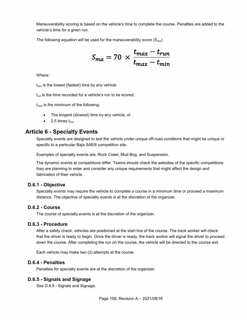
Page 108, Revision A – 2021/08/16
Maneuverability scoring is based on the vehicle’s time to complete the course. Penalties are added to the
vehicle’s time for a given run.
The following equation will be used for the maneuverability score (Sma):
Where:
tmin is the lowest (fastest) time by any vehicle
trun is the time recorded for a vehicle’s run to be scored.
tmax is the minimum of the following:
The longest (slowest) time by any vehicle, or
2.5 times tmin
Article 6 - Specialty Events Specialty events are designed to test the vehicle under unique off-road conditions that might be unique or
specific to a particular Baja SAE® competition site.
Examples of specialty events are: Rock Crawl, Mud Bog, and Suspension.
The dynamic events at competitions differ. Teams should check the websites of the specific competitions
they are planning to enter and consider any unique requirements that might affect the design and
fabrication of their vehicle.
D.6.1 - Objective
Specialty events may require the vehicle to complete a course in a minimum time or proceed a maximum
distance. The objective of specialty events is at the discretion of the organizer.
D.6.2 - Course
The course of specialty events is at the discretion of the organizer.
D.6.3 - Procedure
After a safety check, vehicles are positioned at the start line of the course. The track worker will check
that the driver is ready to begin. Once the driver is ready, the track worker will signal the driver to proceed
down the course. After completing the run on the course, the vehicle will be directed to the course exit.
Each vehicle may make two (2) attempts at the course.
D.6.4 - Penalties
Penalties for specialty events are at the discretion of the organizer.
D.6.5 - Signals and Signage
See D.8.9 - Signals and Signage.
Page 109, Revision A – 2021/08/16
D.6.6 - Scoring
The scoring system and penalties employed by the organizer must adhere to one of the options defined
for either (a) the Maneuverability event, or (b) the Traction event. The maximum number of available
points for the specialty event is 70 points.
Article 7 - Endurance
D.7.1 - Objective
The endurance event assesses each vehicle’s ability to operate continuously and at speed over rough
terrain with obstacles in potentially adverse weather conditions (rain, snow, etc.). The endurance event
may be run for time or for distance. The default is four (4) hours and the vehicle with the most laps (orbits)
around the course is declared the winner.
D.7.2 - Course
The endurance course is a closed loop measuring approximately 0.8 km (0.5 mi.) to 3.2 km (2 mi.). The
endurance course will feature different surfaces (e.g. dirt, grass, sand, mud, gravel, stone, and asphalt).
The endurance course will feature various obstacles and terrain to test the vehicle’s durability, traction,
and speed.
D.7.3 - Procedure
D.7.3.1 - Pre-Gridding
Teams will pre-grid before the endurance event and be placed into starting position based on each team’s
performance in a previous dynamic event, or set of dynamic events, to be determined by the organizer.
Pre-gridding will close at a pre-determined time by SAE and the organizer. Teams late to pre-grid will be
gathered in the fuel area and released to the track after the race has started.
D.7.3.2 - Compliance Check
During pre-gridding, or after pre-gridding closes, vehicle engines will be started and the NTI will perform a
compliance check. During compliance check and gridding, the driver and vehicle may only have one team
member accompany them. The compliance check includes, but is not limited to inspection of the
following:
Helmet Certification
Helmet Fitment and Securement
Safety Harness
Driver Equipment
Driver Wrist Band
Fire Extinguisher
Engine Kill Switches
Brake System
Unprepared drivers or out-of-compliance vehicles deemed unsafe or not ready to drive will be ordered out
of the gridding line by NTI and sent to the paddocks to make corrections. Vehicles not ready to drive must
check in at the fuel area to be admitted to the track.
Page 110, Revision A – 2021/08/16
D.7.3.3 - Gridding
Once the compliance check is complete, vehicles begin to form the grid and approach the start line as
marshaled by track workers or NTI.
D.7.3.4 - Starting
The endurance event may be started by a standing staggered start, rolling start, or holeshot. A standing
staggered start is used to release cars in groups of two with a delay in between groups. A rolling start
allows a run-in distance to the start line. The rolling start may be performed on the course. A holeshot is a
start where all vehicles are lined up equidistant to the first course feature and started all at once. The start
type will be determined by SAE and the organizer.
All vehicles will be considered to have begun the race simultaneously at the time when the starter
releases the first vehicle onto the course regardless of their actual position in the grid.
D.7.3.5 - Running
Endurance will be run as either:
A single four (4) hour race
A predetermined and published distance
Elimination heats followed by a final in which the total time of one elimination heat plus the final is
4 hours. The organizer (with approval from SAE International) will announce the structure of the
event prior to the start.
Vehicles will safely navigate the course and accrue laps (orbits) to be counted and scored.
D.7.3.6 - Driver Change
Vehicle drivers may be changed at any time. Driver changes occur in the Fueling Area.
SAE reserves the right to require at least one driver change during the endurance event.
D.7.3.7 - Refueling
D.7.3.7.1 - Location
The Fueling Zone (FZ) consists of the Fueling Area (FA), Fuel Quarantine Area (FQ), Crew Area (CA)
and Harness Check Area (HC).
Only three (3) people from any given team, including drivers, are allowed within the Fueling Zone (FZ) at
any one time.
Active refueling occurs in the FA. All stored fuel not in use is located in the FQ. Vehicles and drivers will
proceed to the HC before returning to the track.
D.7.3.7.2 - Procedure
Vehicles requiring fuel will exit the track at the designated location and proceed at walking-speed to the
fueling area.
Before refueling, the vehicle must be stopped, the engine shut off, and the driver completely out of the
vehicle. The driver may not be tethered in any way, by harness, communications equipment, or clothing.
Page 111, Revision A – 2021/08/16
Before refueling, a team’s pit crew member must have a fire extinguisher ready and pointed at the fuel
transfer point on the vehicle. The exiting driver is the only team member permitted to remove the fuel tank
cap.
A team refueling their vehicle before the driver is clear of the vehicle or who fail to have a fire extinguisher
present and pointed at the fuel transfer point will be penalized.
The fueling area is to be clear of anyone not immediately servicing a car.
A fire extinguisher must be present and pointed at ANY transfer of fuel, including re-filling a smaller
container from a larger one when a vehicle is not present.
D.7.3.7.3 - Fuel Containers
Vehicles must be refueled using a fuel container no larger than 5.7 L (1.5 gal.) in volume.
D.7.3.7.4 - Fuel Storage
Each team shall have no more than two (2) approved fuel containers in the Fueling Area (FA). Any
additional fuel containers, full or empty, shall be placed in the Fuel Quarantine area (FQ) for the duration
of the endurance event. All fuel must be in the Fueling Zone (FZ) by the time endurance pre-gridding
closes and safety checks begin. Any team found with fuel in the paddocks during the endurance event or
found removing fuel from the Fueling Zone (FZ) without an escort from a NTI or designated official prior to
the end of the endurance event will be assessed a penalty.
If a team wishes to remove their fuel from the Fueling Zone and leave the event site prior to the end of the
endurance event, they must remove their “Passed Tech” sticker and provide it to a National Technical
Inspector in exchange for their fuel.
D.7.3.7.5 - Repairs in Fueling Area
No work requiring a tool may be performed in the Fueling Area. Teams are allowed to make adjustments
that do not require any tools. Examples include driver harness, seat position, spring-damper pre load, etc.
Teams may only have approved fuel containers (see B.6.8 - Fuel Containers), fire extinguishers, and
funnels, if required, in the Fueling Area. Tools of any kind, backpacks, wagons, extra driver equipment,
and coolers are specifically prohibited. Extra driver equipment may be brought to the Fueling Area for use
but extra driver equipment may not be stored in the Fueling Area.
D.7.3.8 - Service
D.7.3.8.1 - Remote Pit
SAE and the organizer may elect to create a remote pit for minor repairs and adjustments.
D.7.3.8.2 - Paddocks
Teams whose vehicle requires service and repairs may exit the track at the designated location and
proceed at walking speed to their paddock. No repairs are permitted on the course at any time.
D.7.3.9 - Recovery
Vehicles disabled on the endurance course may be recovered by track workers, or by a designated
recovery crew. Track workers will attempt to assist disabled vehicles. It is the driver’s responsibility to
assist and cooperate with the course marshals in removing the vehicle. Drivers may not exit the vehicle to
Page 112, Revision A – 2021/08/16
start the engine. Drivers must be seated and secured in the vehicle before track workers will attempt to
restart the engine.
If track workers are unable to assist a disabled vehicle, a recovery crew will transport the disabled vehicle
to the paddocks. Drivers being towed to the paddock are required to remain seated and secured in their
vehicle with all safety equipment on.
Recovery crews are dispatched and operate on a “first come, first serve” basis. No priority will be given to
any team over another.
D.7.3.10 - Finish
The Endurance event is finished when the lead car crosses the finish line after the time limit or distance
has been reached. Vehicles remaining on the track will be allowed to finish their lap. Vehicles in the fuel
zone will not be allowed back on the track after this time.
As vehicles cross the finish line, track workers will direct vehicles to the paddocks or the impound area (if
required). All post-event traffic shall be at walking-speed.
D.7.3.11 - Impound
SAE reserves the right to impound and inspect any vehicle during or after the endurance event. NTI will
direct and instruct teams in impound how to proceed.
Teams may be required to surrender their engine per D.8.8 - Surrender of Engine.
D.7.4 - Penalties
NTI are the only personnel permitted to call and assess penalties during the endurance event. NTI are
distributed throughout the endurance course during the event. Penalties during the endurance race will be
signaled from and vehicles ordered off the track from the black flag area. NTI may stop any vehicle, at
any time, if they believe it no longer complies with the requirements and restrictions of the rules. All timed
penalties are enforced from when the vehicle is in the black flag area, i.e. the time spent being towed
back to the pits, does not count towards the penalty.
D.7.4.1 - Driver Equipment
Any driver that is not using all of the approved and required drivers’ equipment will be flagged.
D.7.4.2 - Mechanical Faults
All cars must remain in the as-approved condition in order to compete; any condition that is deemed to
not meet this requirement will be flagged to make necessary repairs or adjustments. If a vehicle is
stopped by officials for a mechanical fault, the fault must be corrected before it may reenter the event.
D.7.4.3 - Vehicle Assists
Certain areas of the endurance course have been identified as difficult obstacles. If a vehicle is assisted
two times on the same obstacle, the vehicle will be black flagged and the driver warned that one more
assist will result in removal of the vehicle for the remainder of the event.
D.7.4.4 - Roll Over
If a vehicle rolls over (end over end, or over on its side) anywhere on the track two times (in any location,
regardless of driver), the vehicle will be black flagged and the driver warned that one more roll over will
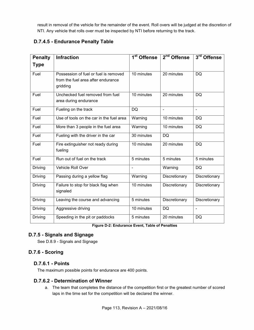
Page 113, Revision A – 2021/08/16
result in removal of the vehicle for the remainder of the event. Roll overs will be judged at the discretion of
NTI. Any vehicle that rolls over must be inspected by NTI before returning to the track.
D.7.4.5 - Endurance Penalty Table
Penalty
Type
Infraction 1st Offense 2nd Offense 3rd Offense
Fuel Possession of fuel or fuel is removed
from the fuel area after endurance
gridding
10 minutes 20 minutes DQ
Fuel Unchecked fuel removed from fuel
area during endurance
10 minutes 20 minutes DQ
Fuel Fueling on the track DQ - -
Fuel Use of tools on the car in the fuel area Warning 10 minutes DQ
Fuel More than 3 people in the fuel area Warning 10 minutes DQ
Fuel Fueling with the driver in the car 30 minutes DQ
Fuel Fire extinguisher not ready during
fueling
10 minutes 20 minutes DQ
Fuel Run out of fuel on the track 5 minutes 5 minutes 5 minutes
Driving Vehicle Roll Over - Warning DQ
Driving Passing during a yellow flag Warning Discretionary Discretionary
Driving Failure to stop for black flag when
signaled
10 minutes Discretionary Discretionary
Driving Leaving the course and advancing 5 minutes Discretionary Discretionary
Driving Aggressive driving 10 minutes DQ -
Driving Speeding in the pit or paddocks 5 minutes 20 minutes DQ
Figure D-2: Endurance Event, Table of Penalties
D.7.5 - Signals and Signage
See D.8.9 - Signals and Signage
D.7.6 - Scoring
D.7.6.1 - Points
The maximum possible points for endurance are 400 points.
D.7.6.2 - Determination of Winner
a. The team that completes the distance of the competition first or the greatest number of scored
laps in the time set for the competition will be declared the winner.
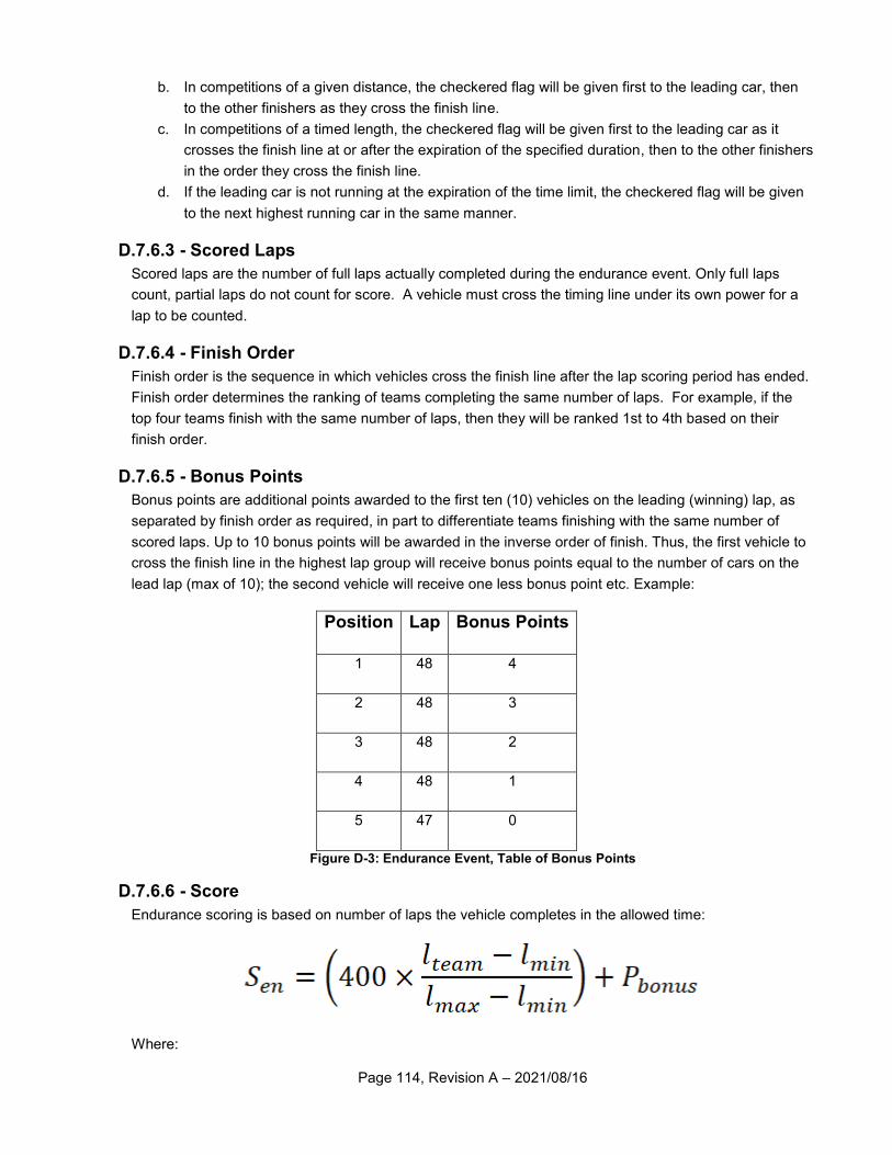
Page 114, Revision A – 2021/08/16
b. In competitions of a given distance, the checkered flag will be given first to the leading car, then
to the other finishers as they cross the finish line.
c. In competitions of a timed length, the checkered flag will be given first to the leading car as it
crosses the finish line at or after the expiration of the specified duration, then to the other finishers
in the order they cross the finish line.
d. If the leading car is not running at the expiration of the time limit, the checkered flag will be given
to the next highest running car in the same manner.
D.7.6.3 - Scored Laps
Scored laps are the number of full laps actually completed during the endurance event. Only full laps
count, partial laps do not count for score. A vehicle must cross the timing line under its own power for a
lap to be counted.
D.7.6.4 - Finish Order
Finish order is the sequence in which vehicles cross the finish line after the lap scoring period has ended.
Finish order determines the ranking of teams completing the same number of laps. For example, if the
top four teams finish with the same number of laps, then they will be ranked 1st to 4th based on their
finish order.
D.7.6.5 - Bonus Points
Bonus points are additional points awarded to the first ten (10) vehicles on the leading (winning) lap, as
separated by finish order as required, in part to differentiate teams finishing with the same number of
scored laps. Up to 10 bonus points will be awarded in the inverse order of finish. Thus, the first vehicle to
cross the finish line in the highest lap group will receive bonus points equal to the number of cars on the
lead lap (max of 10); the second vehicle will receive one less bonus point etc. Example:
Position Lap Bonus Points
1 48 4
2 48 3
3 48 2
4 48 1
5 47 0
Figure D-3: Endurance Event, Table of Bonus Points
D.7.6.6 - Score
Endurance scoring is based on number of laps the vehicle completes in the allowed time:
Where:
Page 115, Revision A – 2021/08/16
Lmax is the maximum number of laps completed by any vehicle.
Lteam is the number of laps completed by the vehicle to be scored.
Lmin is the minimum number of laps completed by any vehicle.
Pbonus is the number of bonus points awarded to a qualifying vehicle.
D.7.6.7 - Heat Plus Final Scoring
When endurance is run as heats plus a final, the points for the event will be distributed between the heats
and the final in proportion to the time/distance of each stage.
Thus, if endurance is run as one (1) hour eliminations plus a three (3) hour final, the four hundred (400)
total points will be allocated as one hundred (100) points to each elimination heat plus three hundred
(300) points to the final.
Article 8 - General Event Procedures and Regulations
D.8.1 - Safety
D.8.1.1 - Safety Vision
Safety is the primary consideration in the design of Baja SAE® vehicles and the conduct of the
competitions. No event or competition is so important that teams and organizers cannot take the time to
work safely. All participants will strive to create a safe competition where all participants return home in
the same condition in which they arrived.
D.8.1.2 - First Aid / CPR / AED
While medical services are always on-site at Baja SAE® events, teams are encouraged to be familiar with
or trained in first aid, CPR, and the use of AED machines.
D.8.1.3 - Approaching Others
All participants are empowered to directly and respectfully approach others if they see a hazardous or
unsafe condition and notify the person in danger. Persons approached regarding a safety concern are
obligated to respectfully acknowledge the situation and are encouraged to thank those who approached
them for their concern.
D.8.1.4 - Responsibility
At all performance events, it is the responsibility of the team to ensure both the vehicle and driver meet
and follow all the requirements and restrictions of the rules.
D.8.1.5 - Personal Protective Equipment
Teams are required to furnish and use their own PPE, appropriate for the task being performed. This
includes, but is not limited to:
Safety Glasses
Gloves
Closed Toe Shoes
Arc Flash Protection
Hearing Protection
Page 116, Revision A – 2021/08/16
D.8.1.6 - Key Hazards
All participants are encouraged to pay careful attention to the following situations:
D.8.1.6.1 - Ascending and Descending
Maintain 3-point contact when ascending and descending stairs, ladders, steps, or tailgates. Watch for
obstructions at the beginning and end of travel.
D.8.1.6.2 - Pinch Points
Stay clear of pinch points from rotating machinery, doors, and other equipment.
D.8.1.6.3 - Hazardous Release of Energy
Stay clear of sparks, chips, swarf, or other high-energy material. Check circuits for live wires before
working on them. Depressurize high pressure air, oil, or water systems before working on them. Take
care when working around presses, rams, or other hydraulic equipment. Use care when jacking or lifting
vehicles or other objects.
D.8.1.6.4 - Vehicle Operations
Do not drive when distracted. Utilize a spotter when backing a vehicle, especially with a trailer.
D.8.1.6.5 - Walking / Path of Travel
Take care to keep all walking paths clear of slip, trip, and fall hazards.
D.8.2 - Rules of Conduct
D.8.2.1 - Sportsmanlike Conduct
All Baja SAE® participants can be proud of the excellent sportsmanship and cooperation among teams
that are two of the hallmarks of the series. Good conduct and compliance with the rules and the official
instructions are expectations and requirements for every team member.
Unsportsmanlike conduct can include arguments with officials, disobedience of official instructions and
the use of abusive or threatening language to any official or other participant. Depending on the
seriousness of the infraction the penalty for such actions can range from a deduction of up to fifty percent
(50%) of the team’s points to expulsion of the entire team. Penalties of this type will only be imposed
after a complete review of the incident by the organizer and SAE International staff.
D.8.2.1.1 - Prohibited Material
Alcoholic beverages, marijuana, firearms, weapons of any type, and illegal materials are prohibited at
Baja SAE® sites during the competition. The penalty for violation of this rule is the immediate expulsion
of the entire team, not just the individual(s) involved. This rule applies to team members, advisors and
any individuals working with the team on-site.
D.8.2.1.2 - Tobacco Products and Electronic Cigarettes
The use of all tobacco and marijuana products or using e-cigarettes on-site is prohibited.
D.8.2.1.3 - Footwear
All individuals on-site shall wear durable and sturdy footwear. Open-toed shoes are explicitly prohibited.
Page 117, Revision A – 2021/08/16
D.8.2.1.4 - Parties
Disruptive parties either on or off-site must be prevented by the faculty advisor or team captain.
D.8.2.1.5 - Housekeeping
Clean-up of trash and debris is the responsibility of the teams. Please make an effort to keep the
paddock area clean and uncluttered. At the close of the day, each team must clean their work area.
D.8.2.1.6 - Site Condition
Please help the organizers keep the site clean. The sites used for Baja SAE® are generally private
property and should be treated as such. Competitors are reminded that they are guests. All trash should
be placed in the receptacles provided. Glass is not allowed on the grounds. Failure to clean the premises
will result in an unsportsmanlike conduct penalty. Competitors are encouraged to clean their areas after
meals.
D.8.2.1.7 - Personal Transportation
The use of motorcycles, quads, bicycles, scooters, skateboards, rollerblades or similar person-carrying or
motor driven devices by team members and spectators in any part of the competition area, including the
paddocks is prohibited.
D.8.2.2 - Spectator Rules
D.8.2.2.1 - General
The organizers typically do not have a direct line of communication with spectators other than on-the-spot
at the competition; thus, the competitors, faculty and volunteers are expected to help inform the
spectators of the safety rules and help restrict spectators to the spectator areas.
D.8.2.2.2 - Alcoholic Beverages
Spectators may not drink or possess alcoholic beverages at any competition location.
D.8.2.2.3 - Access Restriction
Spectators must keep-back a specified distance from the event areas as decided by SAE International
and the organizers and from any area where vehicles are operating under power. Motor vehicle
competitions are potentially dangerous and safety rules will be strictly enforced.
D.8.2.2.4 - Children
A competition site is not a safe place for children and unsupervised young people. Spectators who fail to
strictly control their children will be asked to leave the site.
D.8.2.2.5 - Expulsion
The course officials and organizers have the absolute right to restrict spectator access to any parts of the
site and to eject anyone who violates safety rules or ignores the instructions of officials.
D.8.2.2.6 - Unsafe Conduct
All participants are required to exercise safe practices and avoid unsafe activities at all times during the
competition. The event organizer and SAE have the discretionary authority to impose a just penalty for
any conduct deemed unsafe. All team members will be held to this rule.
Page 118, Revision A – 2021/08/16
D.8.3 - Paddock Rules
D.8.3.1 - Refueling
Before refueling, the vehicle must be stopped, the engine shut off, and the driver completely out of the
vehicle. The driver may not be tethered in any way, by harness, communications equipment, or clothing.
Before refueling, a team’s pit crew member must have a fire extinguisher ready and pointed at the fuel
transfer point on the vehicle. The exiting driver is the only team member permitted to remove the fuel tank
cap.
A team refueling their vehicle before the driver is clear of the vehicle or who fail to have a fire extinguisher
present and pointed at the fuel transfer point will be penalized. For infractions occurring prior to the
endurance race, the penalty will be assessed during the endurance race.
D.8.3.2 - Speed Limit
When a vehicle is driven anywhere except within the practice area or on event courses it must move at
walking speed with a team member walking along side at a normal pace. During the performance events
when the excitement is high, it is particularly important that vehicles move at a walking pace in the
paddocks. The walking speed rule will be strictly enforced and discretionary point penalties will be
assessed for violations.
D.8.3.3 - Escort Required
When a vehicle is driven anywhere except within the practice area or on event courses, it must have a
team member escort the vehicle. The escort shall walk with the vehicle on the right side (to stay close to
the firewall kill switch) and shall remain in the view of the driver at all times. The escort should act as a
spotter to the driver, paying special attention to the vehicle’s blind spots and other vehicles.
Under no circumstances may anyone other than the driver, ride in or on a vehicle.
Escorts shall remain clear and not touch the vehicle when it is in motion and remain within line-of-sight to
the driver.
D.8.3.4 - Team Work Area
The team’s work area should be clearly defined and should be kept uncluttered at all times. When a team
leaves their area, it must be left clean.
D.8.3.5 - Team Vehicles
Only the Baja SAE® vehicles themselves and the teams’ support trucks and trailers are allowed in the
paddocks.
D.8.3.6 - Access Restriction
The organizers may limit the paddocks to team members, faculty advisors and competition officials.
D.8.3.7 - Compressed Gases
Teams shall safely store compressed gas cylinders. Cylinders shall be upright and properly secured by
chain or other method, capped when not in use, and stored such that cylinder temperature is below 52
deg. C (125 deg F).
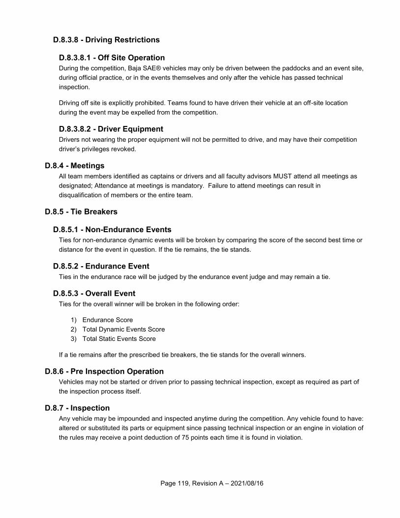
Page 119, Revision A – 2021/08/16
D.8.3.8 - Driving Restrictions
D.8.3.8.1 - Off Site Operation
During the competition, Baja SAE® vehicles may only be driven between the paddocks and an event site,
during official practice, or in the events themselves and only after the vehicle has passed technical
inspection.
Driving off site is explicitly prohibited. Teams found to have driven their vehicle at an off-site location
during the event may be expelled from the competition.
D.8.3.8.2 - Driver Equipment
Drivers not wearing the proper equipment will not be permitted to drive, and may have their competition
driver’s privileges revoked.
D.8.4 - Meetings
All team members identified as captains or drivers and all faculty advisors MUST attend all meetings as
designated; Attendance at meetings is mandatory. Failure to attend meetings can result in
disqualification of members or the entire team.
D.8.5 - Tie Breakers
D.8.5.1 - Non-Endurance Events
Ties for non-endurance dynamic events will be broken by comparing the score of the second best time or
distance for the event in question. If the tie remains, the tie stands.
D.8.5.2 - Endurance Event
Ties in the endurance race will be judged by the endurance event judge and may remain a tie.
D.8.5.3 - Overall Event
Ties for the overall winner will be broken in the following order:
1) Endurance Score
2) Total Dynamic Events Score
3) Total Static Events Score
If a tie remains after the prescribed tie breakers, the tie stands for the overall winners.
D.8.6 - Pre Inspection Operation
Vehicles may not be started or driven prior to passing technical inspection, except as required as part of
the inspection process itself.
D.8.7 - Inspection
Any vehicle may be impounded and inspected anytime during the competition. Any vehicle found to have:
altered or substituted its parts or equipment since passing technical inspection or an engine in violation of
the rules may receive a point deduction of 75 points each time it is found in violation.
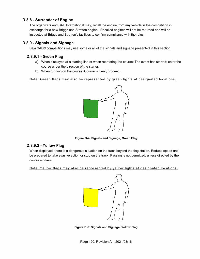
Page 120, Revision A – 2021/08/16
D.8.8 - Surrender of Engine
The organizers and SAE International may, recall the engine from any vehicle in the competition in
exchange for a new Briggs and Stratton engine. Recalled engines will not be returned and will be
inspected at Briggs and Stratton's facilities to confirm compliance with the rules.
D.8.9 - Signals and Signage
Baja SAE® competitions may use some or all of the signals and signage presented in this section.
D.8.9.1 - Green Flag
a) When displayed at a starting line or when reentering the course: The event has started; enter the
course under the direction of the starter.
b) When running on the course: Course is clear, proceed.
Note: Green f lags may a lso be represented by green l ights at des ignated locat ions.
Figure D-4: Signals and Signage, Green Flag
D.8.9.2 - Yellow Flag
When displayed, there is a dangerous situation on the track beyond the flag station. Reduce speed and
be prepared to take evasive action or stop on the track. Passing is not permitted, unless directed by the
course workers.
Note: Yel low f lags may a lso be represented by yel low l ights at des ignated locat ions.
Figure D-5: Signals and Signage, Yellow Flag
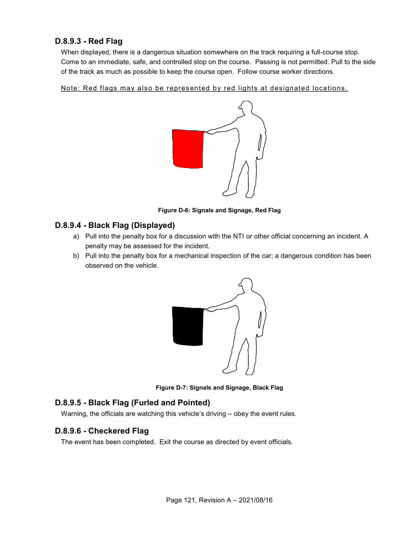
Page 121, Revision A – 2021/08/16
D.8.9.3 - Red Flag
When displayed, there is a dangerous situation somewhere on the track requiring a full-course stop.
Come to an immediate, safe, and controlled stop on the course. Passing is not permitted. Pull to the side
of the track as much as possible to keep the course open. Follow course worker directions.
Note: Red f lags may a lso be represented by red l ights at des ignated locat ions.
Figure D-6: Signals and Signage, Red Flag
D.8.9.4 - Black Flag (Displayed)
a) Pull into the penalty box for a discussion with the NTI or other official concerning an incident. A
penalty may be assessed for the incident.
b) Pull into the penalty box for a mechanical inspection of the car; a dangerous condition has been
observed on the vehicle.
Figure D-7: Signals and Signage, Black Flag
D.8.9.5 - Black Flag (Furled and Pointed)
Warning, the officials are watching this vehicle’s driving – obey the event rules.
D.8.9.6 - Checkered Flag
The event has been completed. Exit the course as directed by event officials.
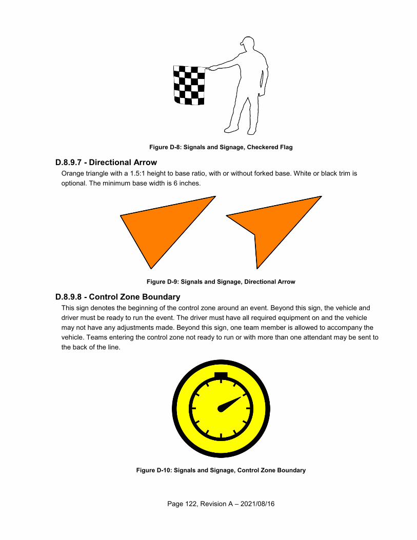
Page 122, Revision A – 2021/08/16
Figure D-8: Signals and Signage, Checkered Flag
D.8.9.7 - Directional Arrow
Orange triangle with a 1.5:1 height to base ratio, with or without forked base. White or black trim is
optional. The minimum base width is 6 inches.
Figure D-9: Signals and Signage, Directional Arrow
D.8.9.8 - Control Zone Boundary
This sign denotes the beginning of the control zone around an event. Beyond this sign, the vehicle and
driver must be ready to run the event. The driver must have all required equipment on and the vehicle
may not have any adjustments made. Beyond this sign, one team member is allowed to accompany the
vehicle. Teams entering the control zone not ready to run or with more than one attendant may be sent to
the back of the line.
Figure D-10: Signals and Signage, Control Zone Boundary
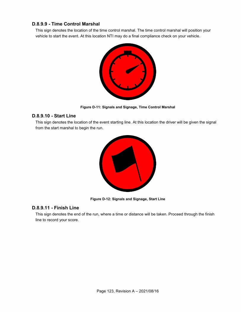
Page 123, Revision A – 2021/08/16
D.8.9.9 - Time Control Marshal
This sign denotes the location of the time control marshal. The time control marshal will position your
vehicle to start the event. At this location NTI may do a final compliance check on your vehicle.
Figure D-11: Signals and Signage, Time Control Marshal
D.8.9.10 - Start Line
This sign denotes the location of the event starting line. At this location the driver will be given the signal
from the start marshal to begin the run.
Figure D-12: Signals and Signage, Start Line
D.8.9.11 - Finish Line
This sign denotes the end of the run, where a time or distance will be taken. Proceed through the finish
line to record your score.
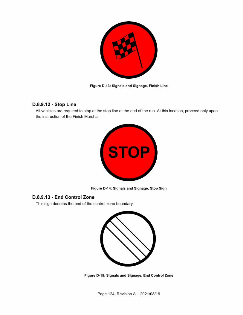
Page 124, Revision A – 2021/08/16
Figure D-13: Signals and Signage, Finish Line
D.8.9.12 - Stop Line
All vehicles are required to stop at the stop line at the end of the run. At this location, proceed only upon
the instruction of the Finish Marshal.
Figure D-14: Signals and Signage, Stop Sign
D.8.9.13 - End Control Zone
This sign denotes the end of the control zone boundary.
Figure D-15: Signals and Signage, End Control Zone
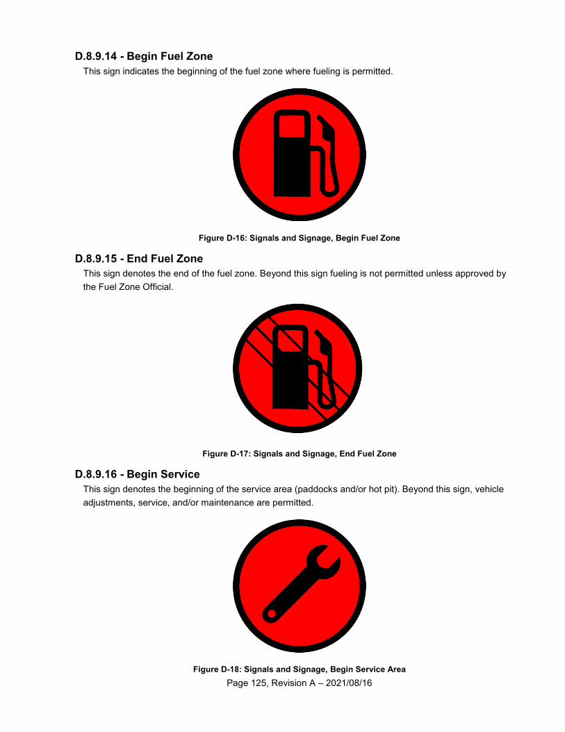
Page 125, Revision A – 2021/08/16
D.8.9.14 - Begin Fuel Zone
This sign indicates the beginning of the fuel zone where fueling is permitted.
Figure D-16: Signals and Signage, Begin Fuel Zone
D.8.9.15 - End Fuel Zone
This sign denotes the end of the fuel zone. Beyond this sign fueling is not permitted unless approved by
the Fuel Zone Official.
Figure D-17: Signals and Signage, End Fuel Zone
D.8.9.16 - Begin Service
This sign denotes the beginning of the service area (paddocks and/or hot pit). Beyond this sign, vehicle
adjustments, service, and/or maintenance are permitted.
Figure D-18: Signals and Signage, Begin Service Area
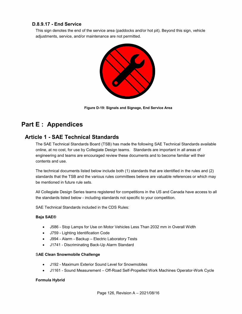
Page 126, Revision A – 2021/08/16
D.8.9.17 - End Service
This sign denotes the end of the service area (paddocks and/or hot pit). Beyond this sign, vehicle
adjustments, service, and/or maintenance are not permitted.
Figure D-19: Signals and Signage, End Service Area
Part E : Appendices
Article 1 - SAE Technical Standards The SAE Technical Standards Board (TSB) has made the following SAE Technical Standards available
online, at no cost, for use by Collegiate Design teams. Standards are important in all areas of
engineering and teams are encouraged review these documents and to become familiar will their
contents and use.
The technical documents listed below include both (1) standards that are identified in the rules and (2)
standards that the TSB and the various rules committees believe are valuable references or which may
be mentioned in future rule sets.
All Collegiate Design Series teams registered for competitions in the US and Canada have access to all
the standards listed below - including standards not specific to your competition.
SAE Technical Standards included in the CDS Rules:
Baja SAE®
J586 - Stop Lamps for Use on Motor Vehicles Less Than 2032 mm in Overall Width
J759 - Lighting Identification Code
J994 - Alarm - Backup – Electric Laboratory Tests
J1741 - Discriminating Back-Up Alarm Standard
SAE Clean Snowmobile Challenge
J192 - Maximum Exterior Sound Level for Snowmobiles
J1161 - Sound Measurement – Off-Road Self-Propelled Work Machines Operator-Work Cycle
Formula Hybrid
Page 127, Revision A – 2021/08/16
J1318 - Gaseous Discharge Warning Lamp for Authorized Emergency, Maintenance and Service
Vehicles
J1673 - High Voltage Automotive Wiring Assembly Design
Formula SAE®
SAE 4130 steel is referenced but no specific standard is identified
SAE Grade 5 bolts are required but no specific standard is identified
SAE Supermileage®
J586 - Stop Lamps for Use on Motor Vehicles Less Than 2032 mm in Overall Width
SAE Technical Standards for Supplemental Use
Baja SAE®
J98 – Personal Protection for General Purpose Industrial Machines – Standard
J183 – Engine Oil Performance and Engine Service Classification - Standard
J306 – Automotive Gear Lubricant Viscosity Classification - Standard
J429 – Mechanical and Material Requirements for Externally Threaded Fasteners – Standard
J512 – Automotive Tube Fittings - Standard
J517 – Hydraulic Hose - Standard
J1166 – Sound Measurement – Off-Road Self-Propelled Work Machines Operator-Work Cycle
J1194 – Rollover Protective Structures (ROPS) for Wheeled Agricultural Tractors
J1362 – Graphical Symbols for Operator Controls and Displays on Off-Road Self-Propelled Work
Machines - Standard
J1614 – Wiring Distribution Systems for Construction, Agricultural and Off-Road Work Machines
J1703 - Motor Vehicle Brake Fluid - Standard
J2030 – Heavy Duty Electrical Connector Performance Standard
J2402 – Road Vehicles – Symbols for Controls, Indicators and Tell-Tales – Standard
SAE Clean Snowmobile Challenge
J44 – Service Brake System Performance Requirements – Snowmobiles - Recommended
Practice
J45 – Brake System Test Procedure – Snowmobiles – Recommended Practice
J68 – Tests for Snowmobile Switching Devices and Components - Recommended Practice
J89 – Dynamic Cushioning Performance Criteria for Snowmobile Seats - Recommended Practice
J92 – Snowmobile Throttle Control Systems – Recommended Practice
J192 – Maximum Exterior Sound Level for Snowmobiles - Recommended Practice
J288 – Snowmobile Fuel Tanks - Recommended Practice
J1161 – Operational Sound Level Measurement Procedure for Snowmobiles - Recommended
Practice
J1222 – Speed Control Assurance for Snowmobiles - Recommended Practice
J1279 – Snowmobile Drive Mechanisms - Recommended Practice
J1282 – Snowmobile Brake Control Systems - Recommended Practice
Page 128, Revision A – 2021/08/16
J2567 – Measurement of Exhaust Sound Levels of Stationary Snowmobiles - Recommended
Practice
Formula SAE®
J183 – Engine Oil Performance and Engine Service Classification - Standard
J306 – Automotive Gear Lubricant Viscosity Classification - Standard
J429 – Mechanical and Material Requirements for Externally Threaded Fasteners – Standard
J452 - General Information – Chemical Compositions, Mechanical and Physical Properties of
SAE Aluminum Casting Alloys – Information Report
J512 – Automotive Tube Fittings - Standard
J517 – Hydraulic Hose - Standard
J637 – Automotive V-Belt Drives – Recommended Practice
J829 – Fuel Tank Filler Cap and Cap Retainer
J1153 - Hydraulic Cylinders for Motor Vehicle Brakes – Test Procedure
J1154 – Hydraulic Master Cylinders for Motor Vehicle Brakes - Performance Requirements -
Standard
J1703 - Motor Vehicle Brake Fluid - Standard
J2045 – Performance Requirements for Fuel System Tubing Assemblies - Standard
J2053 – Brake Master Cylinder Plastic Reservoir Assembly for Road Vehicles – Standard
Formula Hybrid
J1772 – SAE Electric Vehicle and Plug in Hybrid Conductive Charge Coupler
All CDS Competitions
J1739 – Potential Failure Mode and Effects Analysis in Design (Design FMEA) Potential Failure
Mode and Effects Analysis in Manufacturing and Assembly Processes (Process FMEA) and
Potential Failure Mode and Effects Analysis for Machinery (Machinery FMEA)
Article 2 - List of Abbreviations
AED – Automatic External Defibrilator AN/MS – Army/Navy Military Standard CDS – Collegiate Design Series CPR – Cardio Pulmonary Resuscitation CV – Constant Velocity CVT – Continuously Variable Transmission DF – Design Finals DQ - Disqualified FA – Fuel Area FEA – Finite Element Analysis FQ – Fuel Quarantine FZ – Fuel Zone ID – Inside Diameter
IMechE – Institution of Mechanical Engineers LED – Light Emitting Diode MB - Megabyte NTI – National Technical Inspectors OEM – Original Equipment Manufacturer PDF – Portable Document Format by Adobe RF – Radio Frequeny RPM – Revolutions per minute SAE – Society of Automotive Engineers SFI – SEMA Foundation Inc. VDI – Association of German Engineers XLS – Excel Spreadsheet by Microsoft