auto expo 2014 - sae international
TRANSCRIPT
Vol. 1 Issue 3
MOBILITY ENGINEERINGAUTOMOTIVE, AEROSPACE, OFF-HIGHWAY
A quarterly publication of and
TM
June 2014
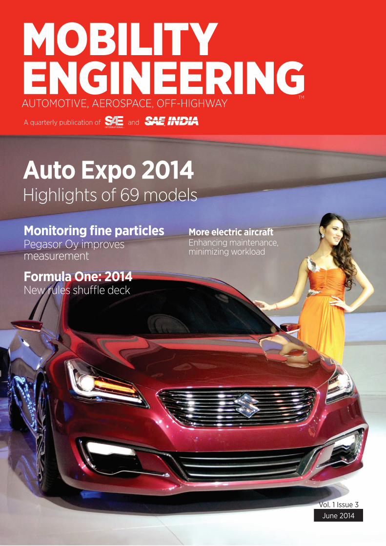
Auto Expo 2014Highlights of 69 models
Monitoring fine particlesPegasor Oy improves measurement
Formula One: 2014New rules shuffle deck
More electric aircraftEnhancing maintenance, minimizing workload

Leveraging our expertise in interconnect technology, Molex is powering the future of the modern Connected Vehicle segment with the HSAutoLink™ II Interconnect System. Offering a compact, low-profile package, the system features data rates above 3.0 Gbps, a ruggedized design capable of withstanding higher than normal mating cycles, and the ability to support a range of communication networks and protocols.
For standard and custom solutions that enhance the on-board experience, turn to Molex. We’re committed to automotive innovation — from the inside out.
NEXT-GENERATION INTERCONNECT TECHNOLOGY DRIVING AUTOMOTIVE INNOVATION
See how we can enhance your designs:molex.com/me/HSAutoLinkII.html
HSAutoLink™II Interconnect System
36 Steering a better path AUTOMOTIVE CHASSIS
New mechanisms developed by NIT Warangal are simpler than the Ackermann type and allow all four wheels to undergo pure rolling.
37 Monitoring fine particle concentrations AUTOMOTIVE TESTING
A robust and versatile system has been developed by Pegasor Oy to measure engine exhaust particulate mass and number more accurately.
39 New rules shuffle the F1 deck AUTOMOTIVE MOTORSPORTS
New turbocharged hybrid-electric power units and revised aerodynamics may scramble the familiar order in Formula One for 2014.
44 No hands, lots of brains AUTOMOTIVE ELECTRONICS
A hefty amount of computing power built with new hardware and software architectures will be needed when vehicles begin taking over more of the driving tasks.
Features
CoverThe Suzuki Ciaz concept car was one of 69 debuts at Auto Expo 2014 in Delhi. Read the highlights of the show starting on page 59.
47 Alternative fuels face challenges AUTOMOTIVE FUELS
With gasoline prices seeming to stabilize and fuel-economy measures taking hold, is there a compelling need for alternative fuels? Automotive engineers offer some surprising reasons why there is.
52 More electric, integrated fuel systems AEROSPACE PROPULSION
Engine system reliability can be improved by advanced electric architectures, while the reduction of hydraulic components, fuel tubes, and fittings can enhance the maintainability of the engine and minimize pilot workload.
56 Making sense of hybrids OFF-HIGHWAY POWERTRAIN
Developers focus on applications that boost productivity while they strive to improve the efficiency of alternative power sources.
Vol. 1 Issue 3
MOBILITY ENGINEERINGAUTOMOTIVE, AEROSPACE, OFF-HIGHWAY
A quarterly publication of and
TM
June 2014
Auto Expo 2014Highlights of 69 models
Monitoring fine particlesPegasor Oy improves measurement
Formula One: 2014New rules shuffle deck
More electric aircraftEnhancing maintenance, minimizing workload
JUNE 2014 1 MOBILITY ENGINEERING
CONTENTS
Departments 04 Editorial Coming clean globally
06 Focus Building upon success
08 SAEINDIA News Student off-roaders kick up dust (and mud)
at Baja event
10 Industry News 10 TRW JV adding products to Indian manufacturing
plant
10 India in need of 1290 aircraft in next 20 years
10 Chennai-built trucks expand Fuso’s African presence
10 Tata Motors enters Philippines market
12 Technology Report 12 Perkins offers electronic engine range for lesser
regulated countries OFF-HIGHWAY POWERTRAIN
12 Maintenance tools for improved engine bearing performance AEROSPACE PROPULSION
14 Novel nanocatalysts for fuel cells AUTOMOTIVE ENERGY
18 Deere offers diagnostics and prognostics in the field OFF-HIGHWAY ELECTRONICS
19 Dassault magnifies focus on its 5X AEROSPACE AVIONICS
20 Touchscreen concepts, thin-foam seats among interiors topics at SAE Congress AUTOMOTIVE INTERIORS
22 Prodrive process ‘clips’ carbon-composite costs by up to 40% AUTOMOTIVE INTERIORS | MATERIALS
25 Audi to increase laser-headlamp applications, says technology chief AUTOMOTIVE BODY | ELECTRONICS
26 Variable trailer design drastically cuts aerodynamic drag TRUCK BODY | SIMULATION
28 Forming a strong bond between materials AUTOMOTIVE MATERIALS
32 Honda, Peugeot stylists make digital renderings a focal point of design AUTOMOTIVE SIMULATION
33 Fuel-economy and greenhouse-gas emissions rules debated AUTOMOTIVE REGULATIONS
35 Job market for engineers remains hot AUTOMOTIVE CAREER
59 Global Vehicles Auto Expo 2014 highlights
71 Ad Index
72 Q&A Bringing Nissan’s future into focus
MOBILITY ENGINEERING2 JUNE 2014
© SAEINDIA and SAE INTERNATIONAL reserves all rights .
No part of this publication and/or website may be reproduced, stored in a retrieval system or transmitted in any form without prior written permission of the Publisher. Permission is only deemed valid if approval is in writing. SAEINDIA and SAE International buys all rights to contributions, text and images, unless previously agreed to in writing. In case of Address/addressee not found return to SAE INDIA, No 1/17Ceebros Arcade, 3rd Cross, Kasturba Nagar, Chennai -600 020. Telefax: 91-44-2441-1904, Phone: 91-44-4215 2280.
CONTENTS
© Copyright 2013-2014 COMSOL. COMSOL, COMSOL Multiphysics, Capture the Concept, COMSOL Desktop, and LiveLink are either registered trademarks or trademarks of COMSOL AB. All other trademarks are the property of their respective owners, and COMSOL AB and its subsidiaries and products are not affiliated with, endorsed by, sponsored by, or supported by those trademark owners. For a list of such trademark owners, see www.comsol.com/trademarks
ELECTRICALAC/DC ModuleRF ModuleWave Optics ModuleMEMS ModulePlasma ModuleSemiconductor Module
MECHANICALHeat Transfer ModuleStructural Mechanics Module Nonlinear Structural Materials ModuleGeomechanics ModuleFatigue ModuleMultibody Dynamics Module Acoustics Module
FLUIDCFD ModuleMixer ModuleMicrofluidics ModuleSubsurface Flow ModulePipe Flow ModuleMolecular Flow Module
CHEMICALChemical Reaction Engineering Module Batteries & Fuel Cells ModuleElectrodeposition Module Corrosion ModuleElectrochemistry Module
MULTIPURPOSEOptimization ModuleMaterial LibraryParticle Tracing Module
INTERFACINGLiveLink™ for MATLAB®
LiveLink™ for Excel®
CAD Import ModuleECAD Import ModuleLiveLink™ for SolidWorks®
LiveLink™ for SpaceClaim®
LiveLink™ for Inventor®
LiveLink™ for AutoCAD®
LiveLink™ for Creo™ ParametricLiveLink™ for Pro/ENGINEER®
LiveLink™ for Solid Edge®
File Import for CATIA® V5
Product Suite
COMSOL Multiphysics
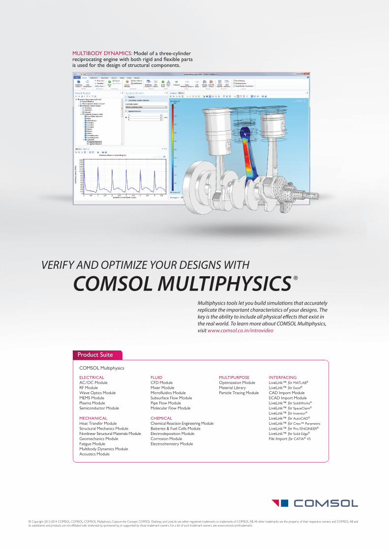
MULTIBODY DYNAMICS: Model of a three-cylinder reciprocating engine with both rigid and flexible parts is used for the design of structural components.
®COMSOL MULTIPHYSICSMultiphysics tools let you build simulations that accurately replicate the important characteristics of your designs. The key is the ability to include all physical effects that exist in the real world. To learn more about COMSOL Multiphysics, visit www.comsol.co.in/introvideo
VERIFY AND OPTIMIZE YOUR DESIGNS WITH
According to a report, “Science and Engineering Indicators,” released in February by the National Science Board (NSB), the policy-making body of the U.S. National Science Foundation (NSF), “it has become increasingly clear that the U.S., Japan, and Europe no longer monopolize the global R&D arena.”
In fact, the report states that since 2001 the share of the world’s R&D performed in the U.S. and Europe has decreased, respectively, from 37 to 30% and from 26 to 22%. Simultaneously, the share of worldwide R&D performed by Asian countries grew from 25 to 34%. China led the Asian expansion, with its global share growing from just 4 to 15%.
In particular, China and South Korea were sin-gled out because both countries have enhanced their domestic R&D “by making significant invest-ments in the S&T [science and technology] research enterprise and enhancing S&T training at universities. China tripled its number of research-ers between 1995 and 2008, whereas South Korea doubled its number between 1995 and 2006.”
The report does not identify what those researchers are actually researching, but it doesn’t seem to be improvements in air quality; in mid-February of this year, Beijing was declared as “almost uninhabitable for human beings,” according a study by the Shanghai Academy of Social Sciences.
The Daily Mail out of the U.K. wrote of the study that Beijing “was only saved from last place [out of 40 major global cities] by Moscow.
Timing of the release of the study was oppor-tune. Bloomberg News reported Feb. 16 that Beijing’s hazardous smog levels had “eased after firework displays traditionally marking the end of the Lunar New Year festival added to hazardous levels of atmospheric contamination. Micro-grams-per-cubic-meter concentration of PM2.5, fine particulates that pose the greatest risk to human health, fell to 74 near Tiananmen Square in central Beijing at 9 a.m., according to data on the website of the city’s air-monitoring center. The average in the previous 24 h was down to 191 from 432 over the same period at yesterday noon.”
The World Health Organization advises day-long exposure of no higher than 25.
According to the NSB, the rise in S&T investe-ments by Asian countries is due to their “atten-tion on crucial sectors of the global economy, including high-tech manufacturing and clean energy.” The report does not talk about crucial sectors of local economies employing people who cannot get to work, or to shop, or do any-thing outside, in a healthy manner, mainly due to a lack of “clean energy.”
From the Feb. 16 Bloomberg report: “‘The recent pollution may be caused by fireworks,’ Li Zhenlong, 30, who works in the energy industry in the Chinese capital, said yesterday. ‘We shouldn’t completely forbid firecrackers. This depends on people’s own free will, while the gov-ernment should largely promote not doing it.’”
While the government comes up with its pro-motion plans urging people to just say no to fire-crackers, maybe it could also focus on other ways to diminish “the recent pollution,” similar to the steps taken by President Obama around the same time in February when he announced that he was directing “the EPA and NHTSA to develop and issue the next phase of medium- and heavy-duty vehicle fuel efficiency and greenhouse gas stan-dards by March 2016.”
According to a White House fact sheet, the first round of standards for such vehicles, finalized in 2011, “is projected to save 530 million barrels of oil and reduce GHG emissions by approximately 270 million t (298 million ton).” (Anyone willing to bet that new standards for the off-highway indus-try can’t be too far behind?)
There have very recently been some clues that Chinese leaders are getting serious about directing some research toward finally addressing the smog problem, such as with the announce-ment of a 10 billion yuan ($1.6 billion) “reward scheme” for cities that significantly reduce pollu-tion. Even if the country today implemented tougher emissions standards for all forms of vehi-cles, and closed all low-tech polluting manufac-turing plants, some experts predict that China could “still have this problem in around 10 or 20 years.”
And that is the primary reason to take action and start today.
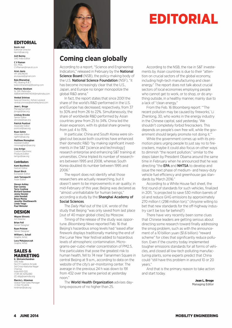
Jean L. Broge Managing Editor
Coming clean globally
MOBILITY ENGINEERING4 JUNE 2014
EDITORIALEDITORIAL Kevin JostEditorial [email protected]
Asit BarmaSAE India Editor
C V RamanED, [email protected]
Arun JauraVP, [email protected]
Bala BharadvajMD, Boeing R & [email protected]
Mathew AbrahamSr. GM, [email protected]
Venkat SrinivasSpecial Director, Ashok [email protected]
Jean L. BrogeManaging [email protected]
Lindsay BrookeSenior [email protected]
Patrick PonticelAssociate [email protected]
Ryan GehmAssociate [email protected]
Matthew MonaghanAssistant [email protected]
Lisa ArrigoCustom Electronic Products [email protected]
ContributorsKami BuchholzDetroit EditorStuart BirchEuropean EditorJack YamaguchiAsian Editor
Steven AshleyDan Carney Terry CostlowRichard GardnerJenny HesslerJohn KendallBruce MoreyJennifer ShuttleworthLinda TregoPaul Weissler
DESIGNWayne SilvonicArt Director
Brian FellSenior Designer
Ryan PristowSenior Designer
William L. SchallGraphic Artist
Lucy MatyjaszczykGraphic Artist
SALES & MARKETINGK. ShriramchandranSAE IndiaNo.1/17, Ceebros Arcade3rd Cross Kasturba NagarChennaiIndia 600 020(T)91-44-42152280(E) [email protected]
Marcie L. HinemanGlobal Field Sales [email protected]

According to a report, “Science and Engineering Indicators,” released in February by the National Science Board (NSB), the policy-making body of the U.S. National Science Foundation (NSF), “it has become increasingly clear that the U.S., Japan, and Europe no longer monopolize the global R&D arena.”
In fact, the report states that since 2001 the share of the world’s R&D performed in the U.S. and Europe has decreased, respectively, from 37 to 30% and from 26 to 22%. Simultaneously, the share of worldwide R&D performed by Asian countries grew from 25 to 34%. China led the Asian expansion, with its global share growing from just 4 to 15%.
In particular, China and South Korea were sin-gled out because both countries have enhanced their domestic R&D “by making significant invest-ments in the S&T [science and technology] research enterprise and enhancing S&T training at universities. China tripled its number of research-ers between 1995 and 2008, whereas South Korea doubled its number between 1995 and 2006.”
The report does not identify what those researchers are actually researching, but it doesn’t seem to be improvements in air quality; in mid-February of this year, Beijing was declared as “almost uninhabitable for human beings,” according a study by the Shanghai Academy of Social Sciences.
The Daily Mail out of the U.K. wrote of the study that Beijing “was only saved from last place [out of 40 major global cities] by Moscow.
Timing of the release of the study was oppor-tune. Bloomberg News reported Feb. 16 that Beijing’s hazardous smog levels had “eased after firework displays traditionally marking the end of the Lunar New Year festival added to hazardous levels of atmospheric contamination. Micro-grams-per-cubic-meter concentration of PM2.5, fine particulates that pose the greatest risk to human health, fell to 74 near Tiananmen Square in central Beijing at 9 a.m., according to data on the website of the city’s air-monitoring center. The average in the previous 24 h was down to 191 from 432 over the same period at yesterday noon.”
The World Health Organization advises day-long exposure of no higher than 25.
According to the NSB, the rise in S&T investe-ments by Asian countries is due to their “atten-tion on crucial sectors of the global economy, including high-tech manufacturing and clean energy.” The report does not talk about crucial sectors of local economies employing people who cannot get to work, or to shop, or do any-thing outside, in a healthy manner, mainly due to a lack of “clean energy.”
From the Feb. 16 Bloomberg report: “‘The recent pollution may be caused by fireworks,’ Li Zhenlong, 30, who works in the energy industry in the Chinese capital, said yesterday. ‘We shouldn’t completely forbid firecrackers. This depends on people’s own free will, while the gov-ernment should largely promote not doing it.’”
While the government comes up with its pro-motion plans urging people to just say no to fire-crackers, maybe it could also focus on other ways to diminish “the recent pollution,” similar to the steps taken by President Obama around the same time in February when he announced that he was directing “the EPA and NHTSA to develop and issue the next phase of medium- and heavy-duty vehicle fuel efficiency and greenhouse gas stan-dards by March 2016.”
According to a White House fact sheet, the first round of standards for such vehicles, finalized in 2011, “is projected to save 530 million barrels of oil and reduce GHG emissions by approximately 270 million t (298 million ton).” (Anyone willing to bet that new standards for the off-highway indus-try can’t be too far behind?)
There have very recently been some clues that Chinese leaders are getting serious about directing some research toward finally addressing the smog problem, such as with the announce-ment of a 10 billion yuan ($1.6 billion) “reward scheme” for cities that significantly reduce pollu-tion. Even if the country today implemented tougher emissions standards for all forms of vehi-cles, and closed all low-tech polluting manufac-turing plants, some experts predict that China could “still have this problem in around 10 or 20 years.”
And that is the primary reason to take action and start today.
Jean L. Broge Managing Editor
Coming clean globally
MOBILITY ENGINEERING4 JUNE 2014
EDITORIALEDITORIAL Kevin JostEditorial [email protected]
Asit BarmaSAE India Editor
C V RamanED, [email protected]
Arun JauraVP, [email protected]
Bala BharadvajMD, Boeing R & [email protected]
Mathew AbrahamSr. GM, [email protected]
Venkat SrinivasSpecial Director, Ashok [email protected]
Jean L. BrogeManaging [email protected]
Lindsay BrookeSenior [email protected]
Patrick PonticelAssociate [email protected]
Ryan GehmAssociate [email protected]
Matthew MonaghanAssistant [email protected]
Lisa ArrigoCustom Electronic Products [email protected]
ContributorsKami BuchholzDetroit EditorStuart BirchEuropean EditorJack YamaguchiAsian Editor
Steven AshleyDan Carney Terry CostlowRichard GardnerJenny HesslerJohn KendallBruce MoreyJennifer ShuttleworthLinda TregoPaul Weissler
DESIGNWayne SilvonicArt Director
Brian FellSenior Designer
Ryan PristowSenior Designer
William L. SchallGraphic Artist
Lucy MatyjaszczykGraphic Artist
SALES & MARKETINGK. ShriramchandranSAE IndiaNo.1/17, Ceebros Arcade3rd Cross Kasturba NagarChennaiIndia 600 020(T)91-44-42152280(E) [email protected]
Marcie L. HinemanGlobal Field Sales [email protected]
GF-6.COM OFFERS extensive access to the latest news, opinions and experti se on the GF-6 specifi cati on. Delivered from an exclusive perspecti ve that you cannot fi nd anywhere else.
> Breaking news
> Exclusive content
> Expert points of view
> Free downloads of key industry presentati ons
> And much more
RELY ON GF-6.COM FOR:
© 2014 The Lubrizol Corporati on. All rights reserved. 140239
Scan this QR code with your mobile device.
The expert view on the GF-6 performance category.
For the insights and in-depth informati on you need, visit GF-6.com.
At the outset, I would like to place on record our warm appreciation to Mr. Shrikant Marathe for providing sterling leadership and taking SAEINDIA on an excellent growth tra-jectory in all spheres of activities during his term as President. There has been significant growth in professional membership, and stu-dent membership touched a new high during his term.
The new Managing Committee, comprised of experts from industry and academia, will align with the objectives set out by leaders in SAEINDIA’s Vision 2020. The document envis-ages an increase in membership to an ambi-tious target of 10,000 professional members, made possible by effective retention of mem-bership and scaling up the satisfaction index of members through active communication and constant interaction. In short, the voice of members will be captured, analyzed, and acted upon toward achieving member delight.
We shall embark on a strong leadership succession plan with increased participation from industry leaders and active volunteer members. We shall endeavor continuously to increase visibility of the SAEINDIA brand. We shall ensure increased frequency of profes-sional development programs and offer SAE International training modules, including web-casts and online programs to our members.
We shall continue to strengthen and rein-force the SAEINDIA office to ensure that we are able to offer a better value proposition in terms of projects, programs, and activities. And we will sharpen our focus on the aero-space and off-highway verticals in partnership with SAE International and other like-minded organizations.
Baja SAEINDIA and Supra SAEINDIA will be organized with continuous improvements based on the experience gained over the years. Strong initiatives to get visibility and recognition from industry and media includ-ing print and electronic media will be planned and implemented.
We shall scale up our Career Start Program with the involvement of a talent acquisition and management team comprising human resource professionals and take it to the next level by increasing the participation signifi-cantly from both the industry and the student communities.
We are determined to consolidate our gains and improve our organizational struc-ture to ensure deliverables are met to the utmost satisfaction of all stakeholders, mak-ing SAEINDIA truly an active and vibrant pre-mier professional society in India.
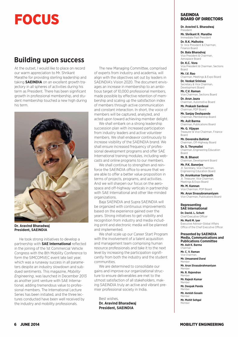
Best wishes,Dr. Aravind BharadwajPresident, SAEINDIA
Building upon success
He took strong initiatives to develop a partnership with SAE International reflected in the joining of the 1st Commercial Vehicle Congress with the 8th Mobility Conference to form the SIMCOMVEC event late last year, which was a runaway success in all parame-ters despite an industry slowdown and sub-dued sentiments. This magazine, Mobility Engineering, was launched in December 2013 as another joint venture with SAE Interna-tional, adding tremendous value to profes-sional members. The International Lecture Series has been initiated, and the three lec-tures conducted have been well received by the industry and mobility professionals.
Dr. Aravind Bharadwaj President, SAEINDIA
MOBILITY ENGINEERING6 JUNE 2014
FOCUS SAEINDIA BOARD OF DIRECTORS
Dr. Aravind S. BharadwajPresident
Mr. Shrikant R. MaratheImmediate Past President
Dr. R.K. MalhotraSr. Vice President & Chairman, Finance Board
Dr. Bala BharadvajVice President & Chairman, Aerospace Board
Dr. K.C. VoraVice President & Chairman, Sections Board
Mr. I.V. RaoChairman, Meetings & Expo Board
Dr. Venkat SrinivasSecretary & Vice Chairman, Development BoardMr. C.V. RamanVice Chairman, Sections Board
Dr. Arun JauraChairman, Automotive Board
Mr. Prakash SardesaiChairman, PDP Board
Mr. Sanjay DeshpandeChairman, Membership Board
Mr. Asit BarmaChairman, Publications Board
Mr. G. VijayanTreasurer & Vice Chairman, Finance Board
Mr. Devendra BahiratChairman, Off-Highway Board
Dr. S. ThrumaliniChairman, Engineering Education Board
Mr. B. BhanotChairman, Development Board
Mr. P.K. BanerjeeJt. Secretary, Vice Chairman, Engineering Education Board
Dr. Arunkumar SampathJt. Treasurer, Vice Chairman, Meetings & Expo Board
Mr. M. KannanVice Chairman, PDP Board
Mr. Arun SivasubramaniyamVice Chairman, Publications Board
Representing SAE InternationalDr. David. L. SchuttChief Executive OfficerMr. Murli M. IyerExecutive Advisor-Global Affairs Office of the Chief Executive Officer
Presented by SAEINDIA Media, Communications and Publications CommitteeMr. Asit K. BarmaChairman
Mr. C. V. RamanVice Chairman,
Mr. Umaanand DuraiMember
Mr. Arun SivasubrahmaniyanMember
Mr. R. RajendranMember
Mr. Rajesh KumarMember
Mr. Deepak PandaMember
Mr. Avnish GosainMember
Mr. Mohit SehgalMember
At the outset, I would like to place on record our warm appreciation to Mr. Shrikant Marathe for providing sterling leadership and taking SAEINDIA on an excellent growth tra-jectory in all spheres of activities during his term as President. There has been significant growth in professional membership, and stu-dent membership touched a new high during his term.
The new Managing Committee, comprised of experts from industry and academia, will align with the objectives set out by leaders in SAEINDIA’s Vision 2020. The document envis-ages an increase in membership to an ambi-tious target of 10,000 professional members, made possible by effective retention of mem-bership and scaling up the satisfaction index of members through active communication and constant interaction. In short, the voice of members will be captured, analyzed, and acted upon toward achieving member delight.
We shall embark on a strong leadership succession plan with increased participation from industry leaders and active volunteer members. We shall endeavor continuously to increase visibility of the SAEINDIA brand. We shall ensure increased frequency of profes-sional development programs and offer SAE International training modules, including web-casts and online programs to our members.
We shall continue to strengthen and rein-force the SAEINDIA office to ensure that we are able to offer a better value proposition in terms of projects, programs, and activities. And we will sharpen our focus on the aero-space and off-highway verticals in partnership with SAE International and other like-minded organizations.
Baja SAEINDIA and Supra SAEINDIA will be organized with continuous improvements based on the experience gained over the years. Strong initiatives to get visibility and recognition from industry and media includ-ing print and electronic media will be planned and implemented.
We shall scale up our Career Start Program with the involvement of a talent acquisition and management team comprising human resource professionals and take it to the next level by increasing the participation signifi-cantly from both the industry and the student communities.
We are determined to consolidate our gains and improve our organizational struc-ture to ensure deliverables are met to the utmost satisfaction of all stakeholders, mak-ing SAEINDIA truly an active and vibrant pre-mier professional society in India.
Best wishes,Dr. Aravind BharadwajPresident, SAEINDIA
Building upon success
He took strong initiatives to develop a partnership with SAE International reflected in the joining of the 1st Commercial Vehicle Congress with the 8th Mobility Conference to form the SIMCOMVEC event late last year, which was a runaway success in all parame-ters despite an industry slowdown and sub-dued sentiments. This magazine, Mobility Engineering, was launched in December 2013 as another joint venture with SAE Interna-tional, adding tremendous value to profes-sional members. The International Lecture Series has been initiated, and the three lec-tures conducted have been well received by the industry and mobility professionals.
Dr. Aravind Bharadwaj President, SAEINDIA
MOBILITY ENGINEERING6 JUNE 2014
FOCUS SAEINDIA BOARD OF DIRECTORS
Dr. Aravind S. BharadwajPresident
Mr. Shrikant R. MaratheImmediate Past President
Dr. R.K. MalhotraSr. Vice President & Chairman, Finance Board
Dr. Bala BharadvajVice President & Chairman, Aerospace Board
Dr. K.C. VoraVice President & Chairman, Sections Board
Mr. I.V. RaoChairman, Meetings & Expo Board
Dr. Venkat SrinivasSecretary & Vice Chairman, Development BoardMr. C.V. RamanVice Chairman, Sections Board
Dr. Arun JauraChairman, Automotive Board
Mr. Prakash SardesaiChairman, PDP Board
Mr. Sanjay DeshpandeChairman, Membership Board
Mr. Asit BarmaChairman, Publications Board
Mr. G. VijayanTreasurer & Vice Chairman, Finance Board
Mr. Devendra BahiratChairman, Off-Highway Board
Dr. S. ThrumaliniChairman, Engineering Education Board
Mr. B. BhanotChairman, Development Board
Mr. P.K. BanerjeeJt. Secretary, Vice Chairman, Engineering Education Board
Dr. Arunkumar SampathJt. Treasurer, Vice Chairman, Meetings & Expo Board
Mr. M. KannanVice Chairman, PDP Board
Mr. Arun SivasubramaniyamVice Chairman, Publications Board
Representing SAE InternationalDr. David. L. SchuttChief Executive OfficerMr. Murli M. IyerExecutive Advisor-Global Affairs Office of the Chief Executive Officer
Presented by SAEINDIA Media, Communications and Publications CommitteeMr. Asit K. BarmaChairman
Mr. C. V. RamanVice Chairman,
Mr. Umaanand DuraiMember
Mr. Arun SivasubrahmaniyanMember
Mr. R. RajendranMember
Mr. Rajesh KumarMember
Mr. Deepak PandaMember
Mr. Avnish GosainMember
Mr. Mohit SehgalMember

MOBILITY ENGINEERING8 JUNE 2014
SAEINDIA News
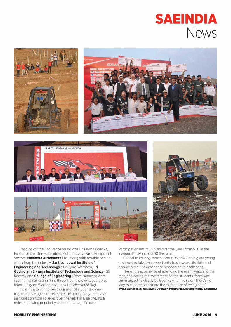
The 7th edition of Baja SAEIndia indeed lived up to its theme, “Raise the Bar.”
Baja SAEIndia gives colleges from across the nation a plat-form to showcase their talent and knowledge by building an off-road recreational four-wheel vehicle that is put through var-ious static and dynamic “tests.” Each team’s goal was to create a safe, easily transported, easily maintained, and fun-to-drive prototype Baja vehicle without any direct involvement from professional fabricators. Teams were also free to design their own transmission as long as they adhered to the 60-km/h (37-mph) speed cap.
From the 327 teams that registered for Baja SAEIndia 2014,
125 qualified for the finale. The three-day event (held Feb. 21-23 near Indore) commenced with a Static Evaluation round in which the engineering design of the vehicles was assessed, as well as the cost to build them and the marketing plan behind them.
The Dynamic Evaluation round tested vehicles for accelera-tion, speed, hill climb, and maneuverability.
Held on the final day was the Endurance event. Teams competed for 4 h on a specially designed off-road course. Assessed was each vehicle’s ability to operate continuously over rough terrain containing obstacles in any weather con-dition.
Student off-roaders kick up dust (and mud) at Baja event
MOBILITY ENGINEERING8 JUNE 2014
SAEINDIA News
The 7th edition of Baja SAEIndia indeed lived up to its theme, “Raise the Bar.”
Baja SAEIndia gives colleges from across the nation a plat-form to showcase their talent and knowledge by building an off-road recreational four-wheel vehicle that is put through var-ious static and dynamic “tests.” Each team’s goal was to create a safe, easily transported, easily maintained, and fun-to-drive prototype Baja vehicle without any direct involvement from professional fabricators. Teams were also free to design their own transmission as long as they adhered to the 60-km/h (37-mph) speed cap.
From the 327 teams that registered for Baja SAEIndia 2014,
125 qualified for the finale. The three-day event (held Feb. 21-23 near Indore) commenced with a Static Evaluation round in which the engineering design of the vehicles was assessed, as well as the cost to build them and the marketing plan behind them.
The Dynamic Evaluation round tested vehicles for accelera-tion, speed, hill climb, and maneuverability.
Held on the final day was the Endurance event. Teams competed for 4 h on a specially designed off-road course. Assessed was each vehicle’s ability to operate continuously over rough terrain containing obstacles in any weather con-dition.
Student off-roaders kick up dust (and mud) at Baja event
MOBILITY ENGINEERING JUNE 2014 9
SAEINDIA News
Flagging off the Endurance round was Dr. Pawan Goenka, Executive Director & President, Automotive & Farm Equipment Sectors, Mahindra & Mahindra Ltd., along with notable person-alities from the industry. Sant Longowal Institute of Engineering and Technology (Junkyard Warriors), Sri Govindram Siksaria Institute of Technology and Science (GS Racers), and College of Engineering (Team Nemesis) were caught in a nail-biting fight throughout the event, but it was team Junkyard Warriors that took the checkered flag.
It was heartening to see thousands of students come together once again to celebrate the spirit of Baja. Increased participation from colleges over the years in Baja SAEIndia reflects growing popularity and national significance.
Participation has multiplied over the years from 500 in the inaugural season to 6500 this year.
Critical to its long-term success, Baja SAEIndia gives young engineering talent an opportunity to showcase its skills and acquire a real-life experience responding to challenges.
The whole experience of attending the event, watching the race, and seeing the excitement on the students’ faces was summarized flawlessly by Goenka when he said, “There’s no way to capture on camera the experience of being here.” Priya Gunasekar, Assistant Director, Programs Development, SAEINDIA
MOBILITY ENGINEERING10 JUNE 2014
Industry NEWSTRW JV adding products to Indian manufacturing plantTRW Automotive Holdings Corp. has announced that its Indian joint venture, RANE TRW Steering Systems Ltd. (RTSSL), has expanded to manufacture TRW airbags and the latest generation of seatbelt systems. RTSSL is applying TRW’s global manufacturing standards to produce driver and passenger airbags and seatbelts at the facility and will make around 320,000 units per annum initially, with an increase in manufactur-ing capacity to approximately 810,000 units in the coming three to five years. “India is a very important market for TRW and we look forward to our contin-ued partnership with Rane to manufac-ture a broader range of advanced tech-nologies that help to protect drivers and occupants there,” said Frank Mueller, Vice President and General Manager for TRW Occupant Safety Systems. “As a global leader in safety, we are committed to providing affordable safety for all drivers and in all regions—to deliver the safety everyone deserves.” RTSSL is a 50-50 joint venture with the Rane Group based in Singaperumal Koil near Chennai. Since 1962, TRW has had a presence in India through its Brakes India Ltd. joint venture with another third party. It has continued to establish further partnerships to offer a full range of safety products and now supports 10 manufacturing locations.
India in need of 1290 aircraft in next 20 yearsAccording to Airbus’ latest market fore-cast, Indian carriers will require 1290 new passenger aircraft valued at US$190 bil-lion between now and 2032 to satisfy surging annual demand. India’s annual passenger traffic growth rate of 8.6% is well above the regional Asia Pacific aver-age growth rate of 6.1% and the world average 4.7%. Of the requirement for 1290 new aircraft, some 73% will be for growth and 27% for replacement. The new passenger aircraft include 913 sin-gle-aisles such as the A320 and A320neo Family, 322 twin-aisles like the A350 XWB and A330, and 56 very large
aircraft such as the A380. By 2032, to-day’s fleet of 343 aircraft will more than triple to some 1233 aircraft. By 2032, Airbus forecasts that 36% of India’s fleet will be wide-bodies, more than doubling today’s level. This is a result of increased capacity of international as well domes-tic routes with larger aircraft like the A330 and A350s.
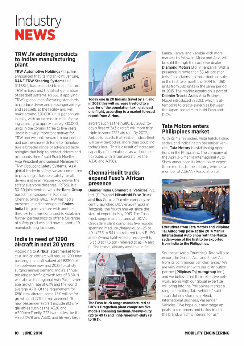
Chennai-built trucks expand Fuso’s African presenceDaimler India Commercial Vehicles Pvt. Ltd. (DICV) and Mitsubishi Fuso Truck and Bus Corp., a Daimler company, re-cently launched DICV-made trucks in Tanzania, the fourth market since the start of export in May 2013. The Fuso truck range manufactured at DICV’s Oragadam plant comprises five models spanning medium-/heavy-duty—25 to 49 t (27.5 to 54 ton) referred to as FJ, FO, and FZ—and light-/medium-duty—9 to 16 t (10 to 17.6 ton) referred to as FA and FI. The trucks, already available in Sri
Lanka, Kenya, and Zambia with more markets to follow in Africa and Asia, will be sold through the exclusive dealer Diamond Motors Ltd. in Tanzania. With a presence in more than 35 African mar-kets, Fuso claims it almost doubled sales in the first two months of 2014 to 1060 units from 580 units in the same period of 2013. The market expansion is part of Daimler Trucks Asia’s Asia Business Model introduced in 2013, which is at-tempting to create synergies between the Japan-based Mitsubishi Fuso and DICV.
Tata Motors enters Philippines marketWith its Manza sedan, Vista hatch, Indigo sedan, and Indica hatch passenger vehi-cles, Tata Motors is establishing opera-tions in the Philippines. The company at the April 3-6 Manila International Auto Show announced its intention to export those models to the country, which is a member of ASEAN (Association of
Today one in 20 Indians travel by air, and in 2032 this will increase fivefold to a quarter of the population taking at least one flight, according to a market forecast report from Airbus.
The Fuso truck range manufactured at DICV’s Oragadam plant comprises five models spanning medium-/heavy-duty (25 to 49 t) and light-/medium-duty (9 to 16 t).
Southeast Asian Countries). Tata will also export the Xenon, Ace, and Super Ace from its commercial vehicles range.” We are very confident with our distribution partner [Pilipinas Taj Autogroup Inc.] and we believe that their extensive net-work, along with our global expertise, will bring into the Philippines market a range of exciting Tata vehicles,” said Tata’s Johnny Oommen, Head, International Business, Passenger Vehicles. “We hope our new range ap-peals to customers and builds trust in the brand, which is integral for us.”
Executives from Tata Motors and Pilipinas Taj Autogroup pose at the 2014 Manila International Auto Show with the Manza sedan—one of the first to be exported from India to the Philippines.

MOBILITY ENGINEERING10 JUNE 2014
Industry NEWSTRW JV adding products to Indian manufacturing plantTRW Automotive Holdings Corp. has announced that its Indian joint venture, RANE TRW Steering Systems Ltd. (RTSSL), has expanded to manufacture TRW airbags and the latest generation of seatbelt systems. RTSSL is applying TRW’s global manufacturing standards to produce driver and passenger airbags and seatbelts at the facility and will make around 320,000 units per annum initially, with an increase in manufactur-ing capacity to approximately 810,000 units in the coming three to five years. “India is a very important market for TRW and we look forward to our contin-ued partnership with Rane to manufac-ture a broader range of advanced tech-nologies that help to protect drivers and occupants there,” said Frank Mueller, Vice President and General Manager for TRW Occupant Safety Systems. “As a global leader in safety, we are committed to providing affordable safety for all drivers and in all regions—to deliver the safety everyone deserves.” RTSSL is a 50-50 joint venture with the Rane Group based in Singaperumal Koil near Chennai. Since 1962, TRW has had a presence in India through its Brakes India Ltd. joint venture with another third party. It has continued to establish further partnerships to offer a full range of safety products and now supports 10 manufacturing locations.
India in need of 1290 aircraft in next 20 yearsAccording to Airbus’ latest market fore-cast, Indian carriers will require 1290 new passenger aircraft valued at US$190 bil-lion between now and 2032 to satisfy surging annual demand. India’s annual passenger traffic growth rate of 8.6% is well above the regional Asia Pacific aver-age growth rate of 6.1% and the world average 4.7%. Of the requirement for 1290 new aircraft, some 73% will be for growth and 27% for replacement. The new passenger aircraft include 913 sin-gle-aisles such as the A320 and A320neo Family, 322 twin-aisles like the A350 XWB and A330, and 56 very large
aircraft such as the A380. By 2032, to-day’s fleet of 343 aircraft will more than triple to some 1233 aircraft. By 2032, Airbus forecasts that 36% of India’s fleet will be wide-bodies, more than doubling today’s level. This is a result of increased capacity of international as well domes-tic routes with larger aircraft like the A330 and A350s.
Chennai-built trucks expand Fuso’s African presenceDaimler India Commercial Vehicles Pvt. Ltd. (DICV) and Mitsubishi Fuso Truck and Bus Corp., a Daimler company, re-cently launched DICV-made trucks in Tanzania, the fourth market since the start of export in May 2013. The Fuso truck range manufactured at DICV’s Oragadam plant comprises five models spanning medium-/heavy-duty—25 to 49 t (27.5 to 54 ton) referred to as FJ, FO, and FZ—and light-/medium-duty—9 to 16 t (10 to 17.6 ton) referred to as FA and FI. The trucks, already available in Sri
Lanka, Kenya, and Zambia with more markets to follow in Africa and Asia, will be sold through the exclusive dealer Diamond Motors Ltd. in Tanzania. With a presence in more than 35 African mar-kets, Fuso claims it almost doubled sales in the first two months of 2014 to 1060 units from 580 units in the same period of 2013. The market expansion is part of Daimler Trucks Asia’s Asia Business Model introduced in 2013, which is at-tempting to create synergies between the Japan-based Mitsubishi Fuso and DICV.
Tata Motors enters Philippines marketWith its Manza sedan, Vista hatch, Indigo sedan, and Indica hatch passenger vehi-cles, Tata Motors is establishing opera-tions in the Philippines. The company at the April 3-6 Manila International Auto Show announced its intention to export those models to the country, which is a member of ASEAN (Association of
Today one in 20 Indians travel by air, and in 2032 this will increase fivefold to a quarter of the population taking at least one flight, according to a market forecast report from Airbus.
The Fuso truck range manufactured at DICV’s Oragadam plant comprises five models spanning medium-/heavy-duty (25 to 49 t) and light-/medium-duty (9 to 16 t).
Southeast Asian Countries). Tata will also export the Xenon, Ace, and Super Ace from its commercial vehicles range.” We are very confident with our distribution partner [Pilipinas Taj Autogroup Inc.] and we believe that their extensive net-work, along with our global expertise, will bring into the Philippines market a range of exciting Tata vehicles,” said Tata’s Johnny Oommen, Head, International Business, Passenger Vehicles. “We hope our new range ap-peals to customers and builds trust in the brand, which is integral for us.”
Executives from Tata Motors and Pilipinas Taj Autogroup pose at the 2014 Manila International Auto Show with the Manza sedan—one of the first to be exported from India to the Philippines.
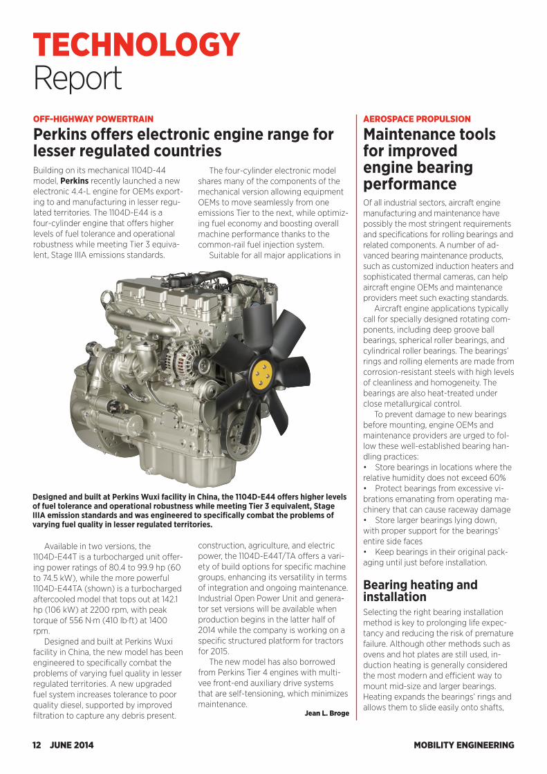
Building on its mechanical 1104D-44 model, Perkins recently launched a new electronic 4.4-L engine for OEMs export-ing to and manufacturing in lesser regu-lated territories. The 1104D-E44 is a four-cylinder engine that offers higher levels of fuel tolerance and operational robustness while meeting Tier 3 equiva-lent, Stage IIIA emissions standards.
The four-cylinder electronic model shares many of the components of the mechanical version allowing equipment OEMs to move seamlessly from one emissions Tier to the next, while optimiz-ing fuel economy and boosting overall machine performance thanks to the common-rail fuel injection system.
Suitable for all major applications in
OFF-HIGHWAY POWERTRAIN
Perkins offers electronic engine range for lesser regulated countries
Available in two versions, the 1104D-E44T is a turbocharged unit offer-ing power ratings of 80.4 to 99.9 hp (60 to 74.5 kW), while the more powerful 1104D-E44TA (shown) is a turbocharged aftercooled model that tops out at 142.1 hp (106 kW) at 2200 rpm, with peak torque of 556 N·m (410 lb·ft) at 1400 rpm.
Designed and built at Perkins Wuxi facility in China, the new model has been engineered to specifically combat the problems of varying fuel quality in lesser regulated territories. A new upgraded fuel system increases tolerance to poor quality diesel, supported by improved filtration to capture any debris present.
construction, agriculture, and electric power, the 1104D-E44T/TA offers a vari-ety of build options for specific machine groups, enhancing its versatility in terms of integration and ongoing maintenance. Industrial Open Power Unit and genera-tor set versions will be available when production begins in the latter half of 2014 while the company is working on a specific structured platform for tractors for 2015.
The new model has also borrowed from Perkins Tier 4 engines with multi-vee front-end auxiliary drive systems that are self-tensioning, which minimizes maintenance.
Jean L. Broge
Designed and built at Perkins Wuxi facility in China, the 1104D-E44 offers higher levels of fuel tolerance and operational robustness while meeting Tier 3 equivalent, Stage IIIA emission standards and was engineered to specifically combat the problems of varying fuel quality in lesser regulated territories.
AEROSPACE PROPULSION
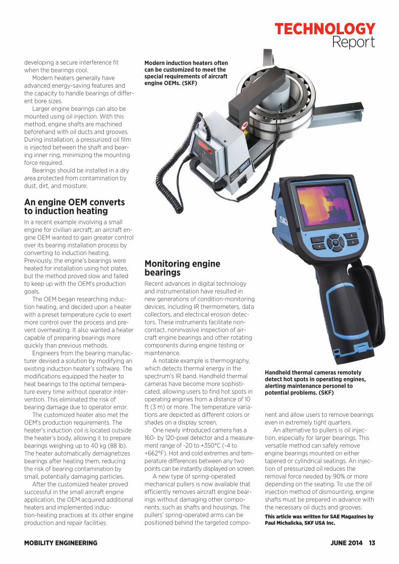
Maintenance tools for improved engine bearing performance Of all industrial sectors, aircraft engine manufacturing and maintenance have possibly the most stringent requirements and specifications for rolling bearings and related components. A number of ad-vanced bearing maintenance products, such as customized induction heaters and sophisticated thermal cameras, can help aircraft engine OEMs and maintenance providers meet such exacting standards.
Aircraft engine applications typically call for specially designed rotating com-ponents, including deep groove ball bearings, spherical roller bearings, and cylindrical roller bearings. The bearings’ rings and rolling elements are made from corrosion-resistant steels with high levels of cleanliness and homogeneity. The bearings are also heat-treated under close metallurgical control.
To prevent damage to new bearings before mounting, engine OEMs and maintenance providers are urged to fol-low these well-established bearing han-dling practices: • Store bearings in locations where the relative humidity does not exceed 60% • Protect bearings from excessive vi-brations emanating from operating ma-chinery that can cause raceway damage • Store larger bearings lying down, with proper support for the bearings’ entire side faces • Keep bearings in their original pack-aging until just before installation. Bearing heating and installation Selecting the right bearing installation method is key to prolonging life expec-tancy and reducing the risk of premature failure. Although other methods such as ovens and hot plates are still used, in-duction heating is generally considered the most modern and efficient way to mount mid-size and larger bearings. Heating expands the bearings’ rings and allows them to slide easily onto shafts,
MOBILITY ENGINEERING12 JUNE 2014
TECHNOLOGYReport
Building on its mechanical 1104D-44 model, Perkins recently launched a new electronic 4.4-L engine for OEMs export-ing to and manufacturing in lesser regu-lated territories. The 1104D-E44 is a four-cylinder engine that offers higher levels of fuel tolerance and operational robustness while meeting Tier 3 equiva-lent, Stage IIIA emissions standards.
The four-cylinder electronic model shares many of the components of the mechanical version allowing equipment OEMs to move seamlessly from one emissions Tier to the next, while optimiz-ing fuel economy and boosting overall machine performance thanks to the common-rail fuel injection system.
Suitable for all major applications in
OFF-HIGHWAY POWERTRAIN
Perkins offers electronic engine range for lesser regulated countries
Available in two versions, the 1104D-E44T is a turbocharged unit offer-ing power ratings of 80.4 to 99.9 hp (60 to 74.5 kW), while the more powerful 1104D-E44TA (shown) is a turbocharged aftercooled model that tops out at 142.1 hp (106 kW) at 2200 rpm, with peak torque of 556 N·m (410 lb·ft) at 1400 rpm.
Designed and built at Perkins Wuxi facility in China, the new model has been engineered to specifically combat the problems of varying fuel quality in lesser regulated territories. A new upgraded fuel system increases tolerance to poor quality diesel, supported by improved filtration to capture any debris present.
construction, agriculture, and electric power, the 1104D-E44T/TA offers a vari-ety of build options for specific machine groups, enhancing its versatility in terms of integration and ongoing maintenance. Industrial Open Power Unit and genera-tor set versions will be available when production begins in the latter half of 2014 while the company is working on a specific structured platform for tractors for 2015.
The new model has also borrowed from Perkins Tier 4 engines with multi-vee front-end auxiliary drive systems that are self-tensioning, which minimizes maintenance.
Jean L. Broge
Designed and built at Perkins Wuxi facility in China, the 1104D-E44 offers higher levels of fuel tolerance and operational robustness while meeting Tier 3 equivalent, Stage IIIA emission standards and was engineered to specifically combat the problems of varying fuel quality in lesser regulated territories.
AEROSPACE PROPULSION
Maintenance tools for improved engine bearing performance Of all industrial sectors, aircraft engine manufacturing and maintenance have possibly the most stringent requirements and specifications for rolling bearings and related components. A number of ad-vanced bearing maintenance products, such as customized induction heaters and sophisticated thermal cameras, can help aircraft engine OEMs and maintenance providers meet such exacting standards.
Aircraft engine applications typically call for specially designed rotating com-ponents, including deep groove ball bearings, spherical roller bearings, and cylindrical roller bearings. The bearings’ rings and rolling elements are made from corrosion-resistant steels with high levels of cleanliness and homogeneity. The bearings are also heat-treated under close metallurgical control.
To prevent damage to new bearings before mounting, engine OEMs and maintenance providers are urged to fol-low these well-established bearing han-dling practices: • Store bearings in locations where the relative humidity does not exceed 60% • Protect bearings from excessive vi-brations emanating from operating ma-chinery that can cause raceway damage • Store larger bearings lying down, with proper support for the bearings’ entire side faces • Keep bearings in their original pack-aging until just before installation. Bearing heating and installation Selecting the right bearing installation method is key to prolonging life expec-tancy and reducing the risk of premature failure. Although other methods such as ovens and hot plates are still used, in-duction heating is generally considered the most modern and efficient way to mount mid-size and larger bearings. Heating expands the bearings’ rings and allows them to slide easily onto shafts,
MOBILITY ENGINEERING12 JUNE 2014
TECHNOLOGYReport developing a secure interference fit
when the bearings cool. Modern heaters generally have
advanced energy-saving features and the capacity to handle bearings of differ-ent bore sizes.
Larger engine bearings can also be mounted using oil injection. With this method, engine shafts are machined beforehand with oil ducts and grooves. During installation, a pressurized oil film is injected between the shaft and bear-ing inner ring, minimizing the mounting force required.
Bearings should be installed in a dry area protected from contamination by dust, dirt, and moisture. An engine OEM converts to induction heating In a recent example involving a small engine for civilian aircraft, an aircraft en-gine OEM wanted to gain greater control over its bearing installation process by converting to induction heating. Previously, the engine’s bearings were heated for installation using hot plates, but the method proved slow and failed to keep up with the OEM’s production goals.
The OEM began researching induc-tion heating, and decided upon a heater with a preset temperature cycle to exert more control over the process and pre-vent overheating. It also wanted a heater capable of preparing bearings more quickly than previous methods.
Engineers from the bearing manufac-turer devised a solution by modifying an existing induction heater’s software. The modifications equipped the heater to heat bearings to the optimal tempera-ture every time without operator inter-vention. This eliminated the risk of bearing damage due to operator error.
The customized heater also met the OEM’s production requirements. The heater’s induction coil is located outside the heater’s body, allowing it to prepare bearings weighing up to 40 kg (88 lb). The heater automatically demagnetizes bearings after heating them, reducing the risk of bearing contamination by small, potentially damaging particles.
After the customized heater proved successful in the small aircraft engine application, the OEM acquired additional heaters and implemented induc-tion-heating practices at its other engine production and repair facilities.
Monitoring engine bearings Recent advances in digital technology and instrumentation have resulted in new generations of condition-monitoring devices, including IR thermometers, data collectors, and electrical erosion detec-tors. These instruments facilitate non-contact, noninvasive inspection of air-craft engine bearings and other rotating components during engine testing or maintenance.
A notable example is thermography, which detects thermal energy in the spectrum’s IR band. Handheld thermal cameras have become more sophisti-cated, allowing users to find hot spots in operating engines from a distance of 10 ft (3 m) or more. The temperature varia-tions are depicted as different colors or shades on a display screen.
One newly introduced camera has a 160- by 120-pixel detector and a measure-ment range of -20 to +350°C (-4 to +662°F). Hot and cold extremes and tem-perature differences between any two points can be instantly displayed on screen.
A new type of spring-operated mechanical pullers is now available that efficiently removes aircraft engine bear-ings without damaging other compo-nents, such as shafts and housings. The pullers’ spring-operated arms can be positioned behind the targeted compo-
nent and allow users to remove bearings even in extremely tight quarters.
An alternative to pullers is oil injec-tion, especially for larger bearings. This versatile method can safely remove engine bearings mounted on either tapered or cylindrical seatings. An injec-tion of pressurized oil reduces the removal force needed by 90% or more depending on the seating. To use the oil injection method of dismounting, engine shafts must be prepared in advance with the necessary oil ducts and grooves. This article was written for SAE Magazines by Paul Michalicka, SKF USA Inc.
Modern induction heaters often can be customized to meet the special requirements of aircraft engine OEMs. (SKF)
Handheld thermal cameras remotely detect hot spots in operating engines, alerting maintenance personel to potential problems. (SKF)
MOBILITY ENGINEERING JUNE 2014 13
TECHNOLOGY Report
One of the biggest obstacles to wide-spread adoption of clean hydrogen fuel-cell-powered cars and trucks is the high price and rarity of the platinum and platinum-family catalysts that the stacks need to make electricity. The costly met-als are critical to carrying out the crucial oxygen-reduction reaction at the fuel-cell cathode, the place where the water “exhaust” forms when oxygen molecules from the air combine with protons filtering through the polymer membrane and electrons arriving via the external circuit.
Recently a team of chemists and materials scientists at the U.S. Department of Energy’s Lawrence Berkeley National Laboratory (LBNL) and Argonne National Laboratory (ANL) developed novel three-dimen-sional “nanoframe” substances that have demonstrated much better catalytic activity (the tendency to facilitate reac-
tions) for the fuel cell’s key cathodic oxi-dation reaction. The order-of-magnitude jump in performance it exhibited com-pared to the state-of-the-art catalysts—platinum nanoparticles deposited onto carbon substrates—is reportedly almost unprecedented. The activity of the cata-lyst also exceeds by an order of magni-tude the 2017 target set for the technology by DOE planners.
The bimetallic catalysts of platinum and nickel feature hollow, high-activity, high-surface-area faces both inside and out, which makes them significantly more efficient and potentially far less expensive than today’s counterparts, according to the team’s recent paper in Science magazine.
The catalysts also work in water-alkali electrolyzers, which split water into oxy-gen and hydrogen and could be a poten-tial source of hydrogen fuel depending on the cost of the electrical power to run
them. Alkaline water electrolyzers have a pair of membrane-separated electrodes immersed in a liquid electrolyte made highly alkaline with caustic potash, or potassium hydroxide. The researchers tested the new electrocatalysts in the crucial cathodic hydrogen-evolution reaction, and activity was enhanced by almost one order of magnitude com-pared to platinum-carbon.
In recent years, intensive worldwide research efforts have focused on creat-ing high-performance electrocatalysts with the minimum costly precious metal content by alloying platinum with cheaper materials and hoping to main-
AUTOMOTIVE ENERGY
Novel nanocatalysts for fuel cells
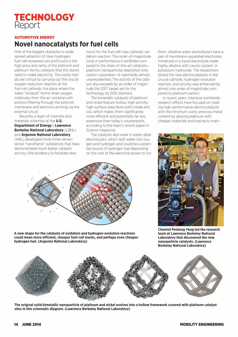
A new shape for the catalysts of oxidation and hydrogen-evolution reactions could mean more efficient, cheaper fuel-cell stacks, and perhaps even cheaper hydrogen fuel. (Argonne National Laboratory)
The original solid bimetallic nanoparticle of platinum and nickel evolves into a hollow framework covered with platinum catalyst sites in this schematic diagram. (Lawrence Berkeley National Laboratory)
Chemist Peidong Yang led the research team at Lawrence Berkeley National Laboratory that discovered the new nanoparticle catalysts. (Lawrence Berkeley National Laboratory)
MOBILITY ENGINEERING14 JUNE 2014
TECHNOLOGY Report
One of the biggest obstacles to wide-spread adoption of clean hydrogen fuel-cell-powered cars and trucks is the high price and rarity of the platinum and platinum-family catalysts that the stacks need to make electricity. The costly met-als are critical to carrying out the crucial oxygen-reduction reaction at the fuel-cell cathode, the place where the water “exhaust” forms when oxygen molecules from the air combine with protons filtering through the polymer membrane and electrons arriving via the external circuit.
Recently a team of chemists and materials scientists at the U.S. Department of Energy’s Lawrence Berkeley National Laboratory (LBNL) and Argonne National Laboratory (ANL) developed novel three-dimen-sional “nanoframe” substances that have demonstrated much better catalytic activity (the tendency to facilitate reac-
tions) for the fuel cell’s key cathodic oxi-dation reaction. The order-of-magnitude jump in performance it exhibited com-pared to the state-of-the-art catalysts—platinum nanoparticles deposited onto carbon substrates—is reportedly almost unprecedented. The activity of the cata-lyst also exceeds by an order of magni-tude the 2017 target set for the technology by DOE planners.
The bimetallic catalysts of platinum and nickel feature hollow, high-activity, high-surface-area faces both inside and out, which makes them significantly more efficient and potentially far less expensive than today’s counterparts, according to the team’s recent paper in Science magazine.
The catalysts also work in water-alkali electrolyzers, which split water into oxy-gen and hydrogen and could be a poten-tial source of hydrogen fuel depending on the cost of the electrical power to run
them. Alkaline water electrolyzers have a pair of membrane-separated electrodes immersed in a liquid electrolyte made highly alkaline with caustic potash, or potassium hydroxide. The researchers tested the new electrocatalysts in the crucial cathodic hydrogen-evolution reaction, and activity was enhanced by almost one order of magnitude com-pared to platinum-carbon.
In recent years, intensive worldwide research efforts have focused on creat-ing high-performance electrocatalysts with the minimum costly precious metal content by alloying platinum with cheaper materials and hoping to main-
AUTOMOTIVE ENERGY
Novel nanocatalysts for fuel cells
A new shape for the catalysts of oxidation and hydrogen-evolution reactions could mean more efficient, cheaper fuel-cell stacks, and perhaps even cheaper hydrogen fuel. (Argonne National Laboratory)
The original solid bimetallic nanoparticle of platinum and nickel evolves into a hollow framework covered with platinum catalyst sites in this schematic diagram. (Lawrence Berkeley National Laboratory)
Chemist Peidong Yang led the research team at Lawrence Berkeley National Laboratory that discovered the new nanoparticle catalysts. (Lawrence Berkeley National Laboratory)
MOBILITY ENGINEERING14 JUNE 2014
TECHNOLOGY Report
tain activity levels. Another promising strategy for improving catalysts involves the development of caged, hollow, or porous materials that contain fewer bur-ied and thus nonfunctional pre-cious-metal atoms. These uncommon geometries can also provide an easier route for tailoring physical and chemical properties as needed, said Peidong Yang, a noted chemist at LBNL and the University of California at Berkeley, who led the work.
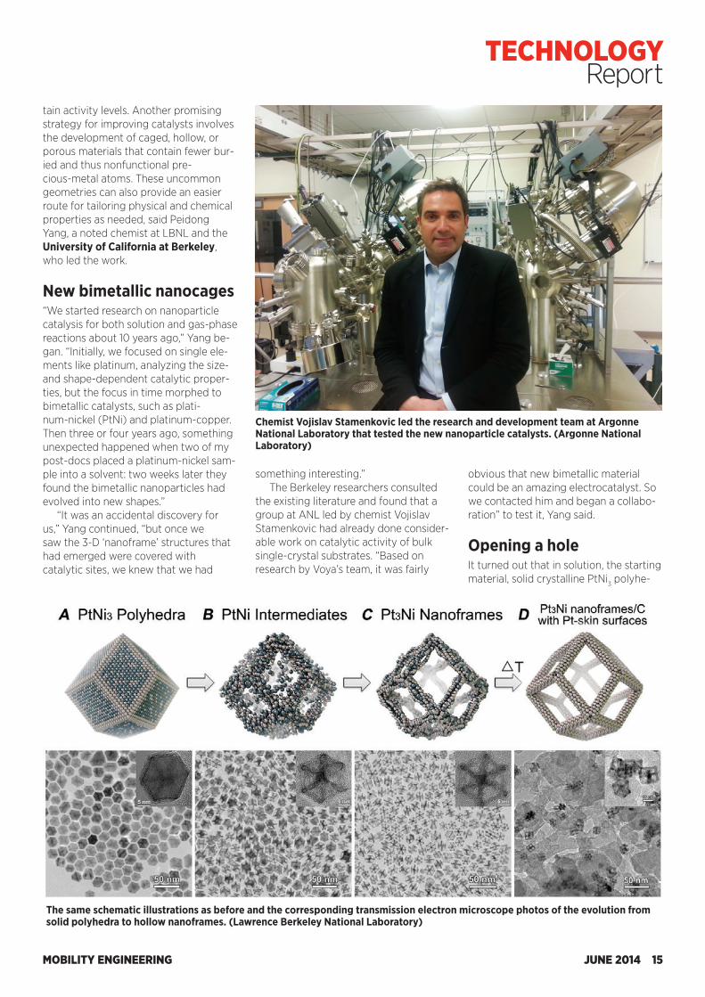
New bimetallic nanocages“We started research on nanoparticle catalysis for both solution and gas-phase reactions about 10 years ago,” Yang be-gan. “Initially, we focused on single ele-ments like platinum, analyzing the size- and shape-dependent catalytic proper-ties, but the focus in time morphed to bimetallic catalysts, such as plati-num-nickel (PtNi) and platinum-copper. Then three or four years ago, something unexpected happened when two of my post-docs placed a platinum-nickel sam-ple into a solvent: two weeks later they found the bimetallic nanoparticles had evolved into new shapes.”
“It was an accidental discovery for us,” Yang continued, “but once we saw the 3-D ‘nanoframe’ structures that had emerged were covered with catalytic sites, we knew that we had
Chemist Vojislav Stamenkovic led the research and development team at Argonne National Laboratory that tested the new nanoparticle catalysts. (Argonne National Laboratory)
The same schematic illustrations as before and the corresponding transmission electron microscope photos of the evolution from solid polyhedra to hollow nanoframes. (Lawrence Berkeley National Laboratory)
something interesting.”The Berkeley researchers consulted
the existing literature and found that a group at ANL led by chemist Vojislav Stamenkovic had already done consider-able work on catalytic activity of bulk single-crystal substrates. “Based on research by Voya’s team, it was fairly
obvious that new bimetallic material could be an amazing electrocatalyst. So we contacted him and began a collabo-ration” to test it, Yang said.
Opening a holeIt turned out that in solution, the starting material, solid crystalline PtNi3 polyhe-
MOBILITY ENGINEERING JUNE 2014 15
TECHNOLOGY Report
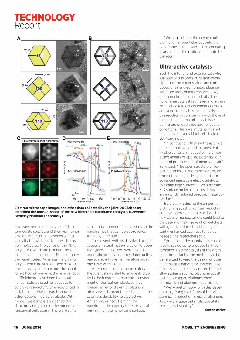
dra, transformed naturally into PtNi in-termediate species, and then via interior erosion into Pt3Ni nanoframes with sur-faces that provide ready access to oxy-gen molecules. The edges of the PtNi3 polyhedra, which are platinum-rich, are maintained in the final Pt3Ni nanoframes, the paper stated. Whereas the original polyhedron consisted of three nickel at-oms for every platinum one, the nanof-rames had, on average, the reverse ratio.
“Polyhedra have been the usual nanostructures used for decades for catalysis research,” Stamenkovic said in a statement. “Our research shows that other options may be available. With frames, we completely opened the structure and got rid of the buried non-functional bulk atoms. There are still a
substantial number of active sites on the nanoframes that can be approached from any direction.”
The solvent, with its dissolved oxygen, causes a natural interior erosion to occur that yields in a hollow twelve-sided, or dodecahedron, nanoframe. Running this reaction at a higher temperature short-ened two weeks to 12 h.
After producing the basic material, the scientists wanted to ensure its stabil-ity in the harsh electrochemical environ-ment of the fuel-cell stack, so they created a “second skin” of platinum atoms over the nanoframe, boosting the catalyst’s durability, to stay active. Annealing, or heat-treating, the nanoframes in argon gas creates a plati-num skin on the nanoframe surfaces.
“We suspect that the oxygen pulls the nickel nanoparticles out onto the nanoframes,” Yang said. “Then annealing in argon pulls the platinum out onto the surfaces.”
Ultra-active catalystsBoth the interior and exterior catalytic surfaces of this open Pt3Ni framework structure, the paper stated, are com-posed of a nano-segregated platinum structure that exhibits enhanced oxy-gen-reduction reaction activity. The nanoframe catalysts achieved more than 36- and 22-fold enhancements in mass and specific activities, respectively, for this reaction in comparison with those of the best platinum-carbon catalysts during prolonged exposure to reaction conditions. The novel material has not been tested in a real fuel-cell stack as yet, Yang noted.
“In contrast to other synthesis proce-dures for hollow nanostructures that involve corrosion induced by harsh oxi-dizing agents or applied potential, our method proceeds spontaneously in air,” Yang said. “The open structure of our platinum/nickel nanoframes addresses some of the major design criteria for advanced nanoscale electrocatalysts, including high surface-to-volume ratio, 3-D surface molecular accessibility, and significantly reduced precious metal uti-lization.”
By greatly reducing the amount of platinum needed for oxygen reduction and hydrogen evolution reactions, the new class of nanocatalysts could lead to the design of next-generation catalysts with greatly reduced cost but signifi-cantly enhanced activities tuned as needed, the researchers said.
Synthesis of the nanoframes can be readily scaled up to produce high-per-formance electrocatalysts at the gram-scale. Importantly, the method can be generalized toward the design of other multimetallic nanoframe systems. The process can be readily applied to other alloy systems such as platinum-cobalt, platinum-copper, platinum-rheni-um-nickel, and platinum-lead-nickel.
“We’re pretty happy with this devel-opment,” Yang said. “It would entail a significant reduction in use of platinum. And we are quite optimistic about its commercial viability.”
Steven Ashley
Electron microscope images and other data collected by the joint DOE lab team identified the unusual shape of the new bimetallic nanoframe catalysts. (Lawrence Berkeley National Laboratory)
MOBILITY ENGINEERING16 JUNE 2014
TECHNOLOGY Report
AR’s EMC solutions make complicated test processes easier and more accurate. Everything is simplified – calibration, testing processes, DUT troubleshooting, and generation of reports directly into convenient formats, such as Microsoft Word or Excel.
These products also have excellent speed, feature a modular design approach and allow their integrated components to be used in a variety of automotive teststandards such as ISO, SAE, CISPR, and OEM requirements. These products have the flexibility to handle engineering development, mitigation and testing to numerous other standards such as: MIL-STD-461, RTCA DO-160, CISPR, EN, ETSI, FCC, ICES, AS/NZS, and VCCI.
The DER2018, with 140 MHz instantaneous bandwidth, is the One Receiver that catches short duration transient disturbances, and scans in seconds. By streamlining testing, this CISPR 16 compliant EMI receiver will change the way you approach testing.
AR’s AS4000 radiated immunity system gives you a turnkey package to perform susceptibility tests, in one self-contained unit up to 40 GHz. Our standard systems can also be customized to include testing to both radiated and conducted immunity and emissions requirements.
The Conducted Immunity (CI) platform offers flexibility to address any Bulk Current Injection (BCI) test method, as well as the ability to access components from the CI housing, such as the power meter and amplifier, to use in other test applications. With three Conducted Immunity Test Systems to choose from, youshould never again have to perform laborious manual CI test procedures or worry about the accuracy of the results.
AR supplies a multitude of unique RF solutions to some of the best-known companies worldwide. Our products are backed by the strongest, most comprehensive warranty in the industry, and a global support network that’s second to none. Call your local AR sales associate for a demonstration.
To learn more, visit www.arworld.us/totalEMC.
In India, contact Complus Systems at www.complus.in or call 91-80-416-83883
rf/microwave instrumentationOther ar divisions: modular rf • receiver systems • ar europeUSA 215-723-8181. For an applications engineer, call 800-933-8181.In Europe, call ar United Kingdom +44 1908 282766 • ar France +33147917530 • ar Deutschland GmbH +49 6101 80270 0 • ar Benelux +31 172 423000
Copyright © 2014 AR. The orange stripe on AR products is Reg. U.S. Pat. & TM. Off.
www.arworld.us
ISO 9001:2008Certified
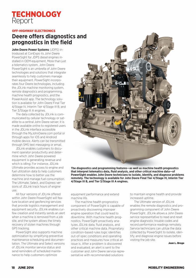
John Deere Power Systems (JDPS) in-troduced at ConExpo its John Deere PowerSight for JDPS diesel engines in-stalled in OEM equipment. More than just a telematics system, John Deere PowerSight is an umbrella of John Deere technologies and solutions that integrate seamlessly to help customers manage their equipment. PowerSight incorpo-rates four Deere technologies, including the JDLink machine monitoring system, remote diagnostics and programming, machine health prognostics, and the PowerAssist app. The technology solu-tion is available for John Deere Final Tier 4/Stage IV, Interim Tier 4/Stage III B, and Tier 3/Stage III A engines.
The data collected by JDLink is com-municated by cellular technology or sat-ellite to a central John Deere server; it is made available online to registered users in the JDLink interface accessible through the MyJohnDeere.com portal or through apps for iOS and Android mobile device. Alerts can be transmitted through SMS text messaging or email.
JDLink enables customers to docu-ment operator productivity and deter-mine which John Deere-powered equipment is generating revenue and which is idling. For instance, JDLink Ultimate provides access to engine and fuel utilization data to help customers determine how to better use the machine and manage fuel consumption. The Ultimate, Select, and Express ver-sions of JDLink track hours of engine use.
All four versions of JDLink offered within John Deere PowerSight will fea-ture location and geofencing services that provide logistics management and equipment security. JDLink enables cur-few creation and instantly sends an alert when a machine is removed from a job site, and the system allows the timely recovery of stolen machines through GPS tracking.
PowerSight also supports machine optimization by simplifying preventive maintenance scheduling and documen-tation. The Ultimate and Select versions of JDLink monitor service status and send reminders of scheduled mainte-nance to help customers optimize
equipment performance and extend machine life.
The machine health prognostics component of PowerSight is capable of proactively discovering improper engine operation that could lead to downtime. With machine health prog-nostics, PowerSight proactively ana-lyzes JDLink data, fluid analysis, and other critical machine data. Proprietary condition-based rules logic identifies out-of-spec conditions and operating practices and measures how critical an issue is. After a problem is discovered and evaluated, an alert is sent to the customer and John Deere service repre-sentative with recommended solutions
to maintain engine health and provide increased uptime.
The Ultimate version of JDLink enables the remote diagnostics and pro-gramming component of John Deere PowerSight. JDLink allows a John Deere service representative to read and reset engine diagnostic trouble codes and record performance readings remotely. Service technicians can utilize the data collected by PowerSight to isolate, iden-tify, and diagnose engine issues before visiting the job site.
Jean L. Broge
The diagnostics and programming features—as well as machine health prognostics that interpret telematics data, fluid analysis, and other critical machine data—of PowerSight enables John Deere technicians to isolate, identify, and diagnose problems remotely. The technology is available for John Deere Final Tier 4/Stage IV, Interim Tier 4/Stage III B, and Tier 3/Stage III A engines.
OFF-HIGHWAY ELECTRONICS
Deere offers diagnostics and prognostics in the field
MOBILITY ENGINEERING18 JUNE 2014
TECHNOLOGY Report
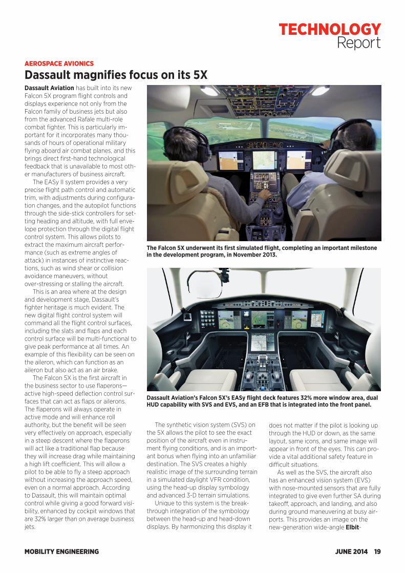
Dassault Aviation has built into its new Falcon 5X program flight controls and displays experience not only from the Falcon family of business jets but also from the advanced Rafale multi-role combat fighter. This is particularly im-portant for it incorporates many thou-sands of hours of operational military flying aboard air combat planes, and this brings direct first-hand technological feedback that is unavailable to most oth-er manufacturers of business aircraft.
The EASy II system provides a very precise flight path control and automatic trim, with adjustments during configura-tion changes, and the autopilot functions through the side-stick controllers for set-ting heading and altitude, with full enve-lope protection through the digital flight control system. This allows pilots to extract the maximum aircraft perfor-mance (such as extreme angles of attack) in instances of instinctive reac-tions, such as wind shear or collision avoidance maneuvers, without over-stressing or stalling the aircraft.
This is an area where at the design and development stage, Dassault’s fighter heritage is much evident. The new digital flight control system will command all the flight control surfaces, including the slats and flaps and each control surface will be multi-functional to give peak performance at all times. An example of this flexibility can be seen on the aileron, which can function as an aileron but also act as an air brake.
The Falcon 5X is the first aircraft in the business sector to use flaperons—active high-speed deflection control sur-faces that can act as flaps or ailerons. The flaperons will always operate in active mode and will enhance roll authority, but the benefit will be seen very effectively on approach, especially in a steep descent where the flaperons will act like a traditional flap because they will increase drag while maintaining a high lift coefficient. This will allow a pilot to be able to fly a steep approach without increasing the approach speed, even on a normal approach. According to Dassault, this will maintain optimal control while giving a good forward visi-bility, enhanced by cockpit windows that are 32% larger than on average business jets.
AEROSPACE AVIONICS
Dassault magnifies focus on its 5X
The Falcon 5X underwent its first simulated flight, completing an important milestone in the development program, in November 2013.
Dassault Aviation’s Falcon 5X’s EASy flight deck features 32% more window area, dual HUD capability with SVS and EVS, and an EFB that is integrated into the front panel.
The synthetic vision system (SVS) on the 5X allows the pilot to see the exact position of the aircraft even in instru-ment flying conditions, and is an import-ant bonus when flying into an unfamiliar destination. The SVS creates a highly realistic image of the surrounding terrain in a simulated daylight VFR condition, using the head-up display symbology and advanced 3-D terrain simulations.
Unique to this system is the break-through integration of the symbology between the head-up and head-down displays. By harmonizing this display it
does not matter if the pilot is looking up through the HUD or down, as the same layout, same icons, and same image will appear in front of the eyes. This can pro-vide a vital additional safety feature in difficult situations.
As well as the SVS, the aircraft also has an enhanced vision system (EVS) with nose-mounted sensors that are fully integrated to give even further SA during takeoff, approach, and landing, and also during ground maneuvering at busy air-ports. This provides an image on the new-generation wide-angle Elbit-
MOBILITY ENGINEERING JUNE 2014 19
TECHNOLOGY Report
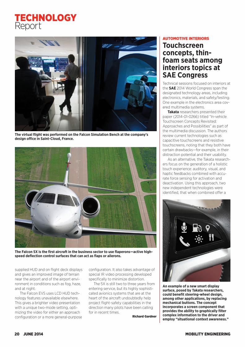
supplied HUD and on flight deck displays and gives an improved image of terrain near the airport and of the airport envi-ronment in conditions such as fog, haze, and at night.
The Falcon EVS uses LCD HUD tech-nology features unavailable elsewhere. This gives a brighter video presentation with a unique two-mode setting, opti-mizing the video for either an approach configuration or a more general-purpose
configuration. It also takes advantage of special IR video processing developed specifically to minimize distortion.
The 5X is still two to three years from entering service, but its highly sophisti-cated avionics systems that are at the heart of the aircraft undoubtedly help project flight-safety capabilities in the direction many pilots have been calling for in recent times.
Richard Gardner
The Falcon 5X is the first aircraft in the business sector to use flaperons—active high-speed deflection control surfaces that can act as flaps or ailerons.
The virtual flight was performed on the Falcon Simulation Bench at the company’s design office in Saint-Cloud, France.
AUTOMOTIVE INTERIORS
Touchscreen concepts, thin-foam seats among interiors topics at SAE CongressTechnical sessions focused on interiors at the SAE 2014 World Congress span the designated technology areas, including electronics, materials, and safety/testing. One example in the electronics area cov-ered multimedia systems.
Takata researchers presented their paper (2014-01-0266) titled “In-vehicle Touchscreen Concepts Revisited: Approaches and Possibilities” as part of the multimedia discussion. The authors review current technologies such as capacitive touchscreens and resistive touchscreens, noting that they both have certain drawbacks—for example, in their distraction potential and their usability.
As an alternative, the Takata research-ers focus on the generation of a holistic touch experience: auditory, visual, and haptic feedbacks combined with accu-rate force sensing for activation and deactivation. Using this approach, two new independent technologies were identified, that when combined offer a
An example of a new smart display surface, posed by Takata researchers, could benefit steering-wheel design, among other applications, by replacing mechanical buttons. The concept incorporates a screen component that provides the ability to graphically filter complex information to the driver and employ “situational context awareness.”
MOBILITY ENGINEERING20 JUNE 2014
TECHNOLOGY Report
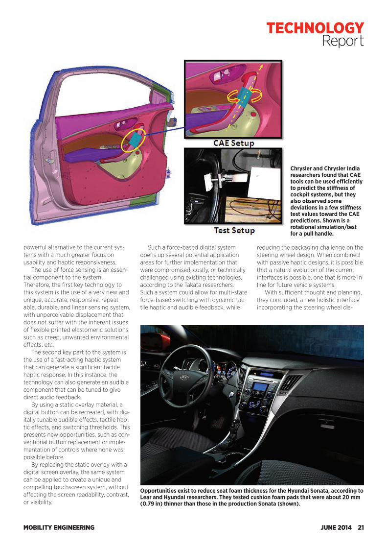
supplied HUD and on flight deck displays and gives an improved image of terrain near the airport and of the airport envi-ronment in conditions such as fog, haze, and at night.
The Falcon EVS uses LCD HUD tech-nology features unavailable elsewhere. This gives a brighter video presentation with a unique two-mode setting, opti-mizing the video for either an approach configuration or a more general-purpose
configuration. It also takes advantage of special IR video processing developed specifically to minimize distortion.
The 5X is still two to three years from entering service, but its highly sophisti-cated avionics systems that are at the heart of the aircraft undoubtedly help project flight-safety capabilities in the direction many pilots have been calling for in recent times.
Richard Gardner
The Falcon 5X is the first aircraft in the business sector to use flaperons—active high-speed deflection control surfaces that can act as flaps or ailerons.
The virtual flight was performed on the Falcon Simulation Bench at the company’s design office in Saint-Cloud, France.
AUTOMOTIVE INTERIORS
Touchscreen concepts, thin-foam seats among interiors topics at SAE CongressTechnical sessions focused on interiors at the SAE 2014 World Congress span the designated technology areas, including electronics, materials, and safety/testing. One example in the electronics area cov-ered multimedia systems.
Takata researchers presented their paper (2014-01-0266) titled “In-vehicle Touchscreen Concepts Revisited: Approaches and Possibilities” as part of the multimedia discussion. The authors review current technologies such as capacitive touchscreens and resistive touchscreens, noting that they both have certain drawbacks—for example, in their distraction potential and their usability.
As an alternative, the Takata research-ers focus on the generation of a holistic touch experience: auditory, visual, and haptic feedbacks combined with accu-rate force sensing for activation and deactivation. Using this approach, two new independent technologies were identified, that when combined offer a
An example of a new smart display surface, posed by Takata researchers, could benefit steering-wheel design, among other applications, by replacing mechanical buttons. The concept incorporates a screen component that provides the ability to graphically filter complex information to the driver and employ “situational context awareness.”
MOBILITY ENGINEERING20 JUNE 2014
TECHNOLOGY Report
Opportunities exist to reduce seat foam thickness for the Hyundai Sonata, according to Lear and Hyundai researchers. They tested cushion foam pads that were about 20 mm (0.79 in) thinner than those in the production Sonata (shown).
Chrysler and Chrysler India researchers found that CAE tools can be used efficiently to predict the stiffness of cockpit systems, but they also observed some deviations in a few stiffness test values toward the CAE predictions. Shown is a rotational simulation/test for a pull handle.
powerful alternative to the current sys-tems with a much greater focus on usability and haptic responsiveness.
The use of force sensing is an essen-tial component to the system. Therefore, the first key technology to this system is the use of a very new and unique, accurate, responsive, repeat-able, durable, and linear sensing system, with unperceivable displacement that does not suffer with the inherent issues of flexible printed elastomeric solutions, such as creep, unwanted environmental effects, etc.
The second key part to the system is the use of a fast-acting haptic system that can generate a significant tactile haptic response. In this instance, the technology can also generate an audible component that can be tuned to give direct audio feedback.
By using a static overlay material, a digital button can be recreated, with dig-itally tunable audible effects, tactile hap-tic effects, and switching thresholds. This presents new opportunities, such as con-ventional button replacement or imple-mentation of controls where none was possible before.
By replacing the static overlay with a digital screen overlay, the same system can be applied to create a unique and compelling touchscreen system, without affecting the screen readability, contrast, or visibility.
Such a force-based digital system opens up several potential application areas for further implementation that were compromised, costly, or technically challenged using existing technologies, according to the Takata researchers. Such a system could allow for multi-state force-based switching with dynamic tac-tile haptic and audible feedback, while
reducing the packaging challenge on the steering wheel design. When combined with passive haptic designs, it is possible that a natural evolution of the current interfaces is possible, one that is more in line for future vehicle systems.
With sufficient thought and planning, they concluded, a new holistic interface incorporating the steering wheel dis-
MOBILITY ENGINEERING JUNE 2014 21
TECHNOLOGY Report
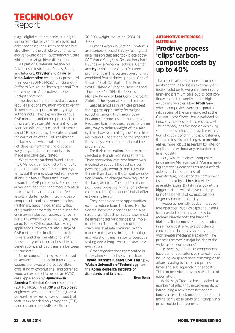
plays, digital center console, and digital instrument cluster can be achieved, not only enhancing the user experience but also allowing the vehicle to continue to evolve toward a semi-autonomous future while minimizing driver distraction.
As part of a Materials session on Advances in Instrument Panels, Seats, and Interiors, Chrysler and Chrysler India Automotive researchers presented their work (2014-01-1025) on “Strength/Stiffness Simulation Techniques and Test Correlations in Automotive Interior Cockpit Systems.”
The development of a cockpit system requires a lot of simulation work to verify its performance prior to prototyping, the authors note. They explain the various CAE methods and techniques used to simulate the virtual stiffness test for the floor console, door trim, and instrument panel (IP) assemblies. They also present the correlation of the CAE results and the lab results, which will reduce prod-uct-development time and cost at an early stage, before the prototype is made and physically tested.
What the researchers found is that the CAE tools can be used efficiently to predict the stiffness of the cockpit sys-tems, but they also observed some devi-ations in a few stiffness test values toward the CAE predictions. Some major areas identified that need more attention to improve the accuracy of the CAE results include: modeling techniques of components and joint representations (fasteners, track, hinge, snaps, welds, etc.); nonlinear material models used for engineering plastics, rubber, and foam parts; the conversion of the physical test setup to the CAE setups like loading applications, constraints, etc.; usage of CAE methods like implicit and explicit solvers, and their benefits and limita-tions; and types of contact used to avoid penetrations, and load transfers between the surfaces.
Other papers in this session focused on advanced materials for interior appli-cations. Renewable, bio-based fillers consisting of coconut shell and torrefied wood are explored for use in an HVAC case application by Hyundai-Kia America Technical Center researchers (2014-01-1026). And JSP and Toyo Seat engineers presented their findings on a polyurethane-free lightweight seat that features expanded polypropylene (EPP) padding and reportedly results in a
30-50% weight reduction (2014-01-1033).
Human Factors in Seating Comfort is an interiors-focused Safety/Testing tech-nical session that also took place at the SAE World Congress. Researchers from Hyundai-Kia America Technical Center and Hyundai Motor Group featured prominently in this session, presenting a combined four technical papers. One of these is “Seat Comfort of Thin Foam Seat Cushions of Varying Densities and Thicknesses” (2014-01-0453), by Michelle Pereny of Lear Corp. and Scott Ziolek of the Hyundai-Kia tech center.
Seat assemblies in vehicles present the biggest opportunity for weight reduction among the various other in-cabin components, the authors note. Reducing foam thickness is seemingly an easy way to reduce weight of the seat system; however, making the foam thin-ner without understanding the impact to the seat system and comfort could be problematic.
For their examination, the researchers selected a Hyundai Sonata seat frame. Three production level seat frames were modified to support the cushion foam pads that were about 20 mm (0.79 in) thinner than those in the current produc-tion Sonata; no changes were required in the back structure. The modified foam pads were poured using the same chemi-cal formulation (foam index) but at differ-ent density levels.
They concluded that opportunities exist to reduce foam thickness for the Sonata; however, changes to the seat structure and cushion suspension must be investigated for a successful imple-mentation. The next phase of their study will evaluate dynamic perfor-mance of the seats through damping and vibration transmissibility objective testing and a long-term ride-and-drive evaluation.
Other organizations represented in the Seating Comfort session include Toyota Technical Center USA, Fiat SpA, Wuhan University of Technology, and the Korea Research Institute of Standards and Science.
Ryan Gehm
AUTOMOTIVE INTERIORS | MATERIALS
Prodrive process ‘clips’ carbon- composite costs by up to 40%The use of carbon-composite compo-nents continues to be an extremely ef-fective solution to weight saving in very high-end premium cars, but its cost con-tinues to limit its application in high-er-volume vehicles. Now, Prodrive—whose composites were incorporated into several of the cars launched at the Geneva Motor Show—has developed an innovative process to help reduce cost. The company has focused on achieving simpler fixing integration via the elimina-tion of costly bonding of clips, fasteners, threaded inserts, and hinges to provide easier, more robust assembly for interior applications without any reduction in finish quality.
Gary White, Prodrive Composites’ Engineering Manager, said: “We are mak-ing composite components more afford-able by reducing the cost of manufacture, not just of the component itself but also by addressing wider assembly issues. By taking a look at the bigger picture, we think we can help bring the benefits of composites to a larger market more quickly.
“Features normally added in a sepa-rate operation, such as clips and inserts for threaded fasteners, can now be molded directly onto the back of high-quality composite panels, produc-ing a more cost-effective part than a conventional bonded assembly, and one with greater mechanical strength. The process removes a major barrier to the wider use of composites.”
Historically, composite components have demanded extensive manual input, including layup and hand trimming oper-ations, leading to increased process times and subsequently higher costs. This can be reduced by increased use of automation.
White says Prodrive has unlocked “a number” of efficiency improvements by introducing a new process that com-bines a plastic back-injection molding to house complex fixtures and fittings via a press-molded component.
MOBILITY ENGINEERING22 JUNE 2014
TECHNOLOGY Report
SAE INTERNATIONAL TECHNICAL PAPERS Technical papers are the foundation for a successful future because they contain applied industry research from fi eld experts, provide for a knowledgeable workforce, and reduce rework to save costs.
We at SAE know that the information presented in our papers is vital to the success of your business. This is why our paper submissions are carefully reviewed by 3 industry experts to ensure our content addresses a new or original contribution to the automotive, aerospace, and commercial vehicle industries.
Contact us today to fi nd a solution that fi ts your research [email protected]+1.888.875.3976+1.724.772.4086 (outside U.S. & Canada)
Instantly access the technical papers you purchase through SAE from your Apple® iPad® via the MyLibrary app!
P140584
PEER-REVIEWED
LONG-TERM REFERENCE VALUE
INNOVATIVE INFORMATION
SOUND CONCLUSIONS
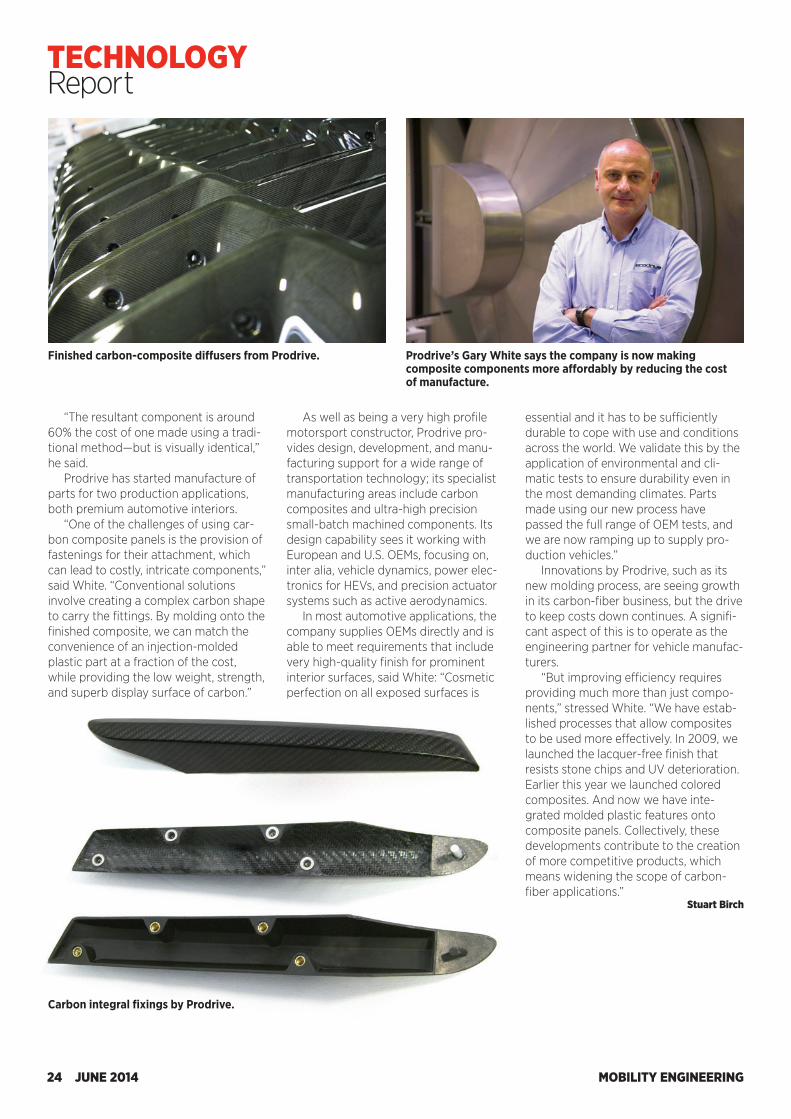
Finished carbon-composite diffusers from Prodrive. Prodrive’s Gary White says the company is now making composite components more affordably by reducing the cost of manufacture.
Carbon integral fixings by Prodrive.
“The resultant component is around 60% the cost of one made using a tradi-tional method—but is visually identical,” he said.
Prodrive has started manufacture of parts for two production applications, both premium automotive interiors.
“One of the challenges of using car-bon composite panels is the provision of fastenings for their attachment, which can lead to costly, intricate components,” said White. “Conventional solutions involve creating a complex carbon shape to carry the fittings. By molding onto the finished composite, we can match the convenience of an injection-molded plastic part at a fraction of the cost, while providing the low weight, strength, and superb display surface of carbon.”
As well as being a very high profile motorsport constructor, Prodrive pro-vides design, development, and manu-facturing support for a wide range of transportation technology; its specialist manufacturing areas include carbon composites and ultra-high precision small-batch machined components. Its design capability sees it working with European and U.S. OEMs, focusing on, inter alia, vehicle dynamics, power elec-tronics for HEVs, and precision actuator systems such as active aerodynamics.
In most automotive applications, the company supplies OEMs directly and is able to meet requirements that include very high-quality finish for prominent interior surfaces, said White: “Cosmetic perfection on all exposed surfaces is
essential and it has to be sufficiently durable to cope with use and conditions across the world. We validate this by the application of environmental and cli-matic tests to ensure durability even in the most demanding climates. Parts made using our new process have passed the full range of OEM tests, and we are now ramping up to supply pro-duction vehicles.”
Innovations by Prodrive, such as its new molding process, are seeing growth in its carbon-fiber business, but the drive to keep costs down continues. A signifi-cant aspect of this is to operate as the engineering partner for vehicle manufac-turers.
“But improving efficiency requires providing much more than just compo-nents,” stressed White. “We have estab-lished processes that allow composites to be used more effectively. In 2009, we launched the lacquer-free finish that resists stone chips and UV deterioration. Earlier this year we launched colored composites. And now we have inte-grated molded plastic features onto composite panels. Collectively, these developments contribute to the creation of more competitive products, which means widening the scope of carbon- fiber applications.”
Stuart Birch
MOBILITY ENGINEERING24 JUNE 2014
TECHNOLOGY Report
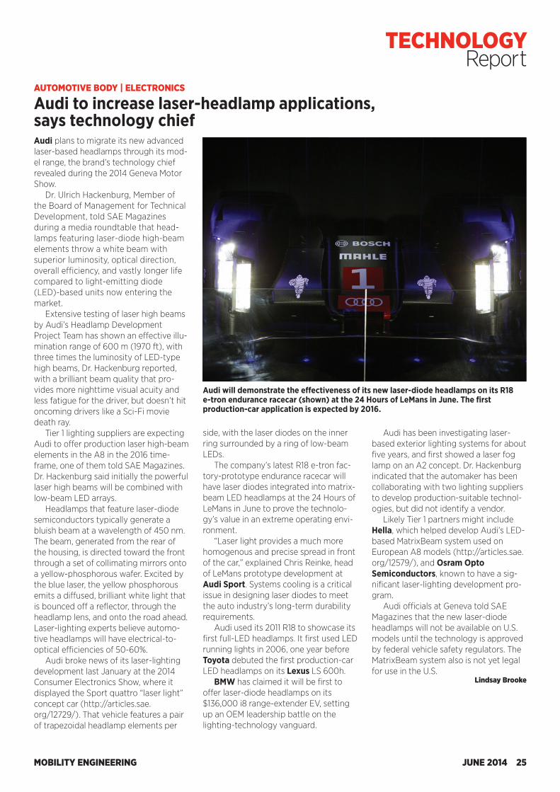
Audi plans to migrate its new advanced laser-based headlamps through its mod-el range, the brand’s technology chief revealed during the 2014 Geneva Motor Show.
Dr. Ulrich Hackenburg, Member of the Board of Management for Technical Development, told SAE Magazines during a media roundtable that head-lamps featuring laser-diode high-beam elements throw a white beam with superior luminosity, optical direction, overall efficiency, and vastly longer life compared to light-emitting diode (LED)-based units now entering the market.
Extensive testing of laser high beams by Audi’s Headlamp Development Project Team has shown an effective illu-mination range of 600 m (1970 ft), with three times the luminosity of LED-type high beams, Dr. Hackenburg reported, with a brilliant beam quality that pro-vides more nighttime visual acuity and less fatigue for the driver, but doesn’t hit oncoming drivers like a Sci-Fi movie death ray.
Tier 1 lighting suppliers are expecting Audi to offer production laser high-beam elements in the A8 in the 2016 time-frame, one of them told SAE Magazines. Dr. Hackenburg said initially the powerful laser high beams will be combined with low-beam LED arrays.
Headlamps that feature laser-diode semiconductors typically generate a bluish beam at a wavelength of 450 nm. The beam, generated from the rear of the housing, is directed toward the front through a set of collimating mirrors onto a yellow-phosphorous wafer. Excited by the blue laser, the yellow phosphorous emits a diffused, brilliant white light that is bounced off a reflector, through the headlamp lens, and onto the road ahead. Laser-lighting experts believe automo-tive headlamps will have electrical-to- optical efficiencies of 50-60%.
Audi broke news of its laser-lighting development last January at the 2014 Consumer Electronics Show, where it displayed the Sport quattro “laser light” concept car (http://articles.sae.org/12729/). That vehicle features a pair of trapezoidal headlamp elements per
side, with the laser diodes on the inner ring surrounded by a ring of low-beam LEDs.
The company’s latest R18 e-tron fac-tory-prototype endurance racecar will have laser diodes integrated into matrix-beam LED headlamps at the 24 Hours of LeMans in June to prove the technolo-gy’s value in an extreme operating envi-ronment.
“Laser light provides a much more homogenous and precise spread in front of the car,” explained Chris Reinke, head of LeMans prototype development at Audi Sport. Systems cooling is a critical issue in designing laser diodes to meet the auto industry’s long-term durability requirements.
Audi used its 2011 R18 to showcase its first full-LED headlamps. It first used LED running lights in 2006, one year before Toyota debuted the first production-car LED headlamps on its Lexus LS 600h.
BMW has claimed it will be first to offer laser-diode headlamps on its $136,000 i8 range-extender EV, setting up an OEM leadership battle on the lighting-technology vanguard.
Audi has been investigating laser-based exterior lighting systems for about five years, and first showed a laser fog lamp on an A2 concept. Dr. Hackenburg indicated that the automaker has been collaborating with two lighting suppliers to develop production-suitable technol-ogies, but did not identify a vendor.
Likely Tier 1 partners might include Hella, which helped develop Audi’s LED-based MatrixBeam system used on European A8 models (http://articles.sae.org/12579/), and Osram Opto Semiconductors, known to have a sig-nificant laser-lighting development pro-gram.
Audi officials at Geneva told SAE Magazines that the new laser-diode headlamps will not be available on U.S. models until the technology is approved by federal vehicle safety regulators. The MatrixBeam system also is not yet legal for use in the U.S.
Lindsay Brooke
AUTOMOTIVE BODY | ELECTRONICS
Audi to increase laser-headlamp applications, says technology chief
Audi will demonstrate the effectiveness of its new laser-diode headlamps on its R18 e-tron endurance racecar (shown) at the 24 Hours of LeMans in June. The first production-car application is expected by 2016.
MOBILITY ENGINEERING JUNE 2014 25
TECHNOLOGY Report
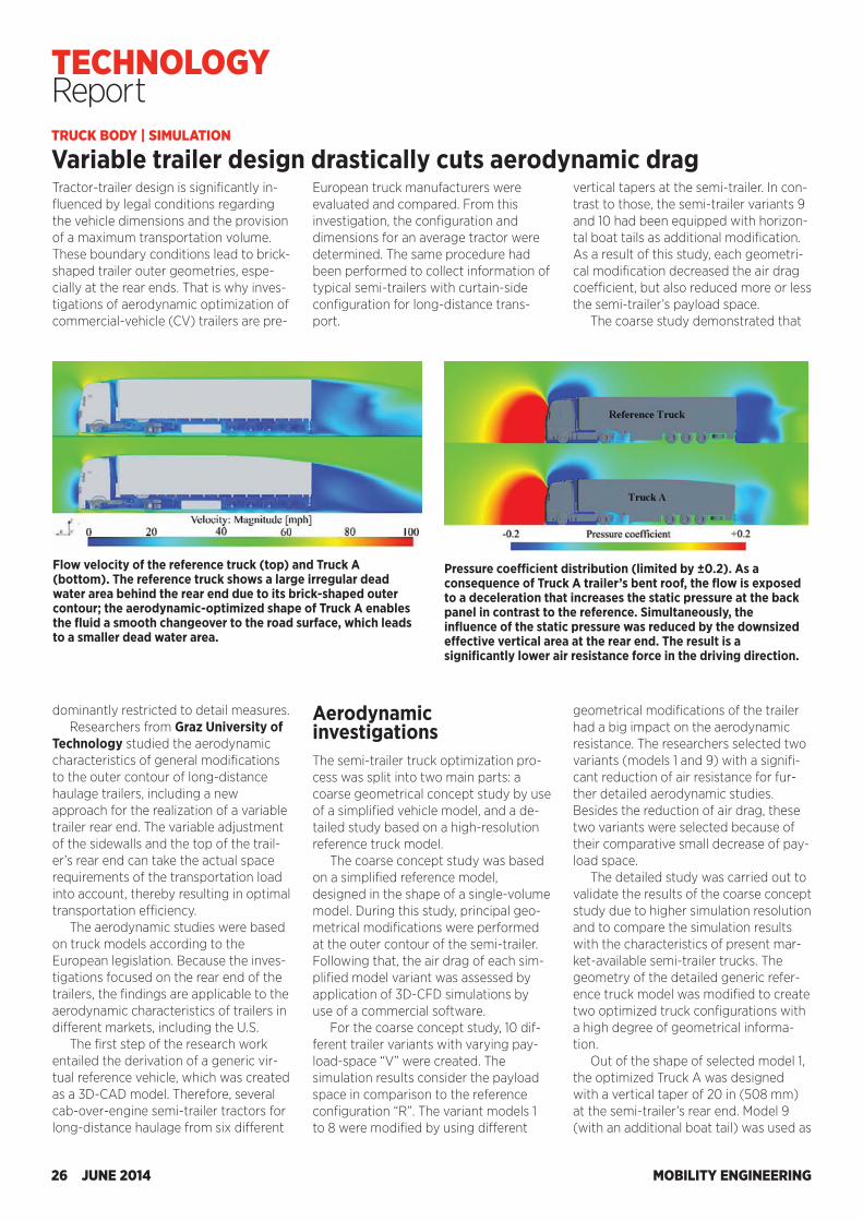
TRUCK BODY | SIMULATION
Variable trailer design drastically cuts aerodynamic dragTractor-trailer design is significantly in-fluenced by legal conditions regarding the vehicle dimensions and the provision of a maximum transportation volume. These boundary conditions lead to brick-shaped trailer outer geometries, espe-cially at the rear ends. That is why inves-tigations of aerodynamic optimization of commercial-vehicle (CV) trailers are pre-
European truck manufacturers were evaluated and compared. From this investigation, the configuration and dimensions for an average tractor were determined. The same procedure had been performed to collect information of typical semi-trailers with curtain-side configuration for long-distance trans-port.
vertical tapers at the semi-trailer. In con-trast to those, the semi-trailer variants 9 and 10 had been equipped with horizon-tal boat tails as additional modification. As a result of this study, each geometri-cal modification decreased the air drag coefficient, but also reduced more or less the semi-trailer’s payload space.
The coarse study demonstrated that
Pressure coefficient distribution (limited by ±0.2). As a consequence of Truck A trailer’s bent roof, the flow is exposed to a deceleration that increases the static pressure at the back panel in contrast to the reference. Simultaneously, the influence of the static pressure was reduced by the downsized effective vertical area at the rear end. The result is a significantly lower air resistance force in the driving direction.
Flow velocity of the reference truck (top) and Truck A (bottom). The reference truck shows a large irregular dead water area behind the rear end due to its brick-shaped outer contour; the aerodynamic-optimized shape of Truck A enables the fluid a smooth changeover to the road surface, which leads to a smaller dead water area.
dominantly restricted to detail measures. Researchers from Graz University of
Technology studied the aerodynamic characteristics of general modifications to the outer contour of long-distance haulage trailers, including a new approach for the realization of a variable trailer rear end. The variable adjustment of the sidewalls and the top of the trail-er’s rear end can take the actual space requirements of the transportation load into account, thereby resulting in optimal transportation efficiency.
The aerodynamic studies were based on truck models according to the European legislation. Because the inves-tigations focused on the rear end of the trailers, the findings are applicable to the aerodynamic characteristics of trailers in different markets, including the U.S.
The first step of the research work entailed the derivation of a generic vir-tual reference vehicle, which was created as a 3D-CAD model. Therefore, several cab-over-engine semi-trailer tractors for long-distance haulage from six different
Aerodynamic investigations The semi-trailer truck optimization pro-cess was split into two main parts: a coarse geometrical concept study by use of a simplified vehicle model, and a de-tailed study based on a high-resolution reference truck model.
The coarse concept study was based on a simplified reference model, designed in the shape of a single-volume model. During this study, principal geo-metrical modifications were performed at the outer contour of the semi-trailer. Following that, the air drag of each sim-plified model variant was assessed by application of 3D-CFD simulations by use of a commercial software.
For the coarse concept study, 10 dif-ferent trailer variants with varying pay-load-space “V” were created. The simulation results consider the payload space in comparison to the reference configuration “R”. The variant models 1 to 8 were modified by using different
geometrical modifications of the trailer had a big impact on the aerodynamic resistance. The researchers selected two variants (models 1 and 9) with a signifi-cant reduction of air resistance for fur-ther detailed aerodynamic studies. Besides the reduction of air drag, these two variants were selected because of their comparative small decrease of pay-load space.
The detailed study was carried out to validate the results of the coarse concept study due to higher simulation resolution and to compare the simulation results with the characteristics of present mar-ket-available semi-trailer trucks. The geometry of the detailed generic refer-ence truck model was modified to create two optimized truck configurations with a high degree of geometrical informa-tion.
Out of the shape of selected model 1, the optimized Truck A was designed with a vertical taper of 20 in (508 mm) at the semi-trailer’s rear end. Model 9 (with an additional boat tail) was used as
MOBILITY ENGINEERING26 JUNE 2014
TECHNOLOGY Report
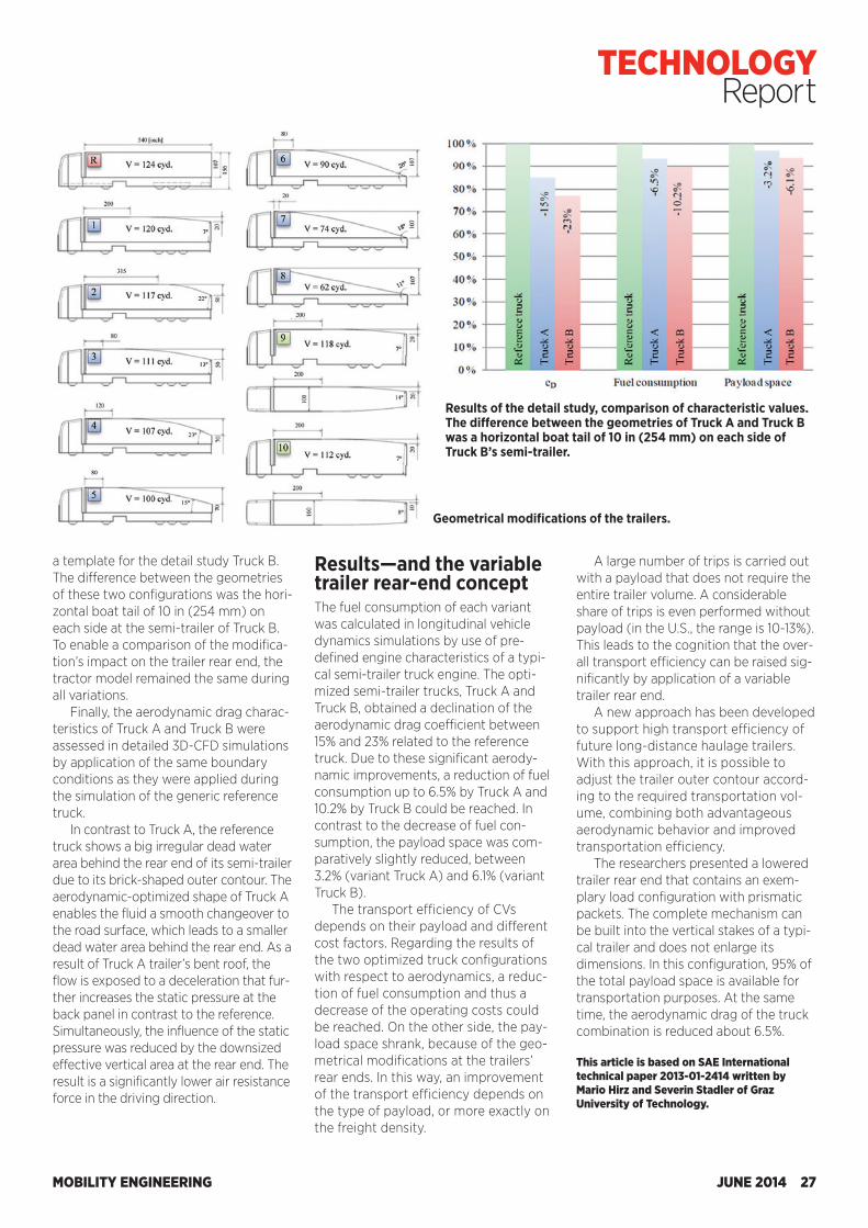
TRUCK BODY | SIMULATION
Variable trailer design drastically cuts aerodynamic dragTractor-trailer design is significantly in-fluenced by legal conditions regarding the vehicle dimensions and the provision of a maximum transportation volume. These boundary conditions lead to brick-shaped trailer outer geometries, espe-cially at the rear ends. That is why inves-tigations of aerodynamic optimization of commercial-vehicle (CV) trailers are pre-
European truck manufacturers were evaluated and compared. From this investigation, the configuration and dimensions for an average tractor were determined. The same procedure had been performed to collect information of typical semi-trailers with curtain-side configuration for long-distance trans-port.
vertical tapers at the semi-trailer. In con-trast to those, the semi-trailer variants 9 and 10 had been equipped with horizon-tal boat tails as additional modification. As a result of this study, each geometri-cal modification decreased the air drag coefficient, but also reduced more or less the semi-trailer’s payload space.
The coarse study demonstrated that
Pressure coefficient distribution (limited by ±0.2). As a consequence of Truck A trailer’s bent roof, the flow is exposed to a deceleration that increases the static pressure at the back panel in contrast to the reference. Simultaneously, the influence of the static pressure was reduced by the downsized effective vertical area at the rear end. The result is a significantly lower air resistance force in the driving direction.
Flow velocity of the reference truck (top) and Truck A (bottom). The reference truck shows a large irregular dead water area behind the rear end due to its brick-shaped outer contour; the aerodynamic-optimized shape of Truck A enables the fluid a smooth changeover to the road surface, which leads to a smaller dead water area.
dominantly restricted to detail measures. Researchers from Graz University of
Technology studied the aerodynamic characteristics of general modifications to the outer contour of long-distance haulage trailers, including a new approach for the realization of a variable trailer rear end. The variable adjustment of the sidewalls and the top of the trail-er’s rear end can take the actual space requirements of the transportation load into account, thereby resulting in optimal transportation efficiency.
The aerodynamic studies were based on truck models according to the European legislation. Because the inves-tigations focused on the rear end of the trailers, the findings are applicable to the aerodynamic characteristics of trailers in different markets, including the U.S.
The first step of the research work entailed the derivation of a generic vir-tual reference vehicle, which was created as a 3D-CAD model. Therefore, several cab-over-engine semi-trailer tractors for long-distance haulage from six different
Aerodynamic investigations The semi-trailer truck optimization pro-cess was split into two main parts: a coarse geometrical concept study by use of a simplified vehicle model, and a de-tailed study based on a high-resolution reference truck model.
The coarse concept study was based on a simplified reference model, designed in the shape of a single-volume model. During this study, principal geo-metrical modifications were performed at the outer contour of the semi-trailer. Following that, the air drag of each sim-plified model variant was assessed by application of 3D-CFD simulations by use of a commercial software.
For the coarse concept study, 10 dif-ferent trailer variants with varying pay-load-space “V” were created. The simulation results consider the payload space in comparison to the reference configuration “R”. The variant models 1 to 8 were modified by using different
geometrical modifications of the trailer had a big impact on the aerodynamic resistance. The researchers selected two variants (models 1 and 9) with a signifi-cant reduction of air resistance for fur-ther detailed aerodynamic studies. Besides the reduction of air drag, these two variants were selected because of their comparative small decrease of pay-load space.
The detailed study was carried out to validate the results of the coarse concept study due to higher simulation resolution and to compare the simulation results with the characteristics of present mar-ket-available semi-trailer trucks. The geometry of the detailed generic refer-ence truck model was modified to create two optimized truck configurations with a high degree of geometrical informa-tion.
Out of the shape of selected model 1, the optimized Truck A was designed with a vertical taper of 20 in (508 mm) at the semi-trailer’s rear end. Model 9 (with an additional boat tail) was used as
MOBILITY ENGINEERING26 JUNE 2014
TECHNOLOGY Report
a template for the detail study Truck B. The difference between the geometries of these two configurations was the hori-zontal boat tail of 10 in (254 mm) on each side at the semi-trailer of Truck B. To enable a comparison of the modifica-tion’s impact on the trailer rear end, the tractor model remained the same during all variations.
Finally, the aerodynamic drag charac-teristics of Truck A and Truck B were assessed in detailed 3D-CFD simulations by application of the same boundary conditions as they were applied during the simulation of the generic reference truck.
In contrast to Truck A, the reference truck shows a big irregular dead water area behind the rear end of its semi-trailer due to its brick-shaped outer contour. The aerodynamic-optimized shape of Truck A enables the fluid a smooth changeover to the road surface, which leads to a smaller dead water area behind the rear end. As a result of Truck A trailer’s bent roof, the flow is exposed to a deceleration that fur-ther increases the static pressure at the back panel in contrast to the reference. Simultaneously, the influence of the static pressure was reduced by the downsized effective vertical area at the rear end. The result is a significantly lower air resistance force in the driving direction.
Geometrical modifications of the trailers.
Results—and the variable trailer rear-end conceptThe fuel consumption of each variant was calculated in longitudinal vehicle dynamics simulations by use of pre-defined engine characteristics of a typi-cal semi-trailer truck engine. The opti-mized semi-trailer trucks, Truck A and Truck B, obtained a declination of the aerodynamic drag coefficient between 15% and 23% related to the reference truck. Due to these significant aerody-namic improvements, a reduction of fuel consumption up to 6.5% by Truck A and 10.2% by Truck B could be reached. In contrast to the decrease of fuel con-sumption, the payload space was com-paratively slightly reduced, between 3.2% (variant Truck A) and 6.1% (variant Truck B).
The transport efficiency of CVs depends on their payload and different cost factors. Regarding the results of the two optimized truck configurations with respect to aerodynamics, a reduc-tion of fuel consumption and thus a decrease of the operating costs could be reached. On the other side, the pay-load space shrank, because of the geo-metrical modifications at the trailers’ rear ends. In this way, an improvement of the transport efficiency depends on the type of payload, or more exactly on the freight density.
A large number of trips is carried out with a payload that does not require the entire trailer volume. A considerable share of trips is even performed without payload (in the U.S., the range is 10-13%). This leads to the cognition that the over-all transport efficiency can be raised sig-nificantly by application of a variable trailer rear end.
A new approach has been developed to support high transport efficiency of future long-distance haulage trailers. With this approach, it is possible to adjust the trailer outer contour accord-ing to the required transportation vol-ume, combining both advantageous aerodynamic behavior and improved transportation efficiency.
The researchers presented a lowered trailer rear end that contains an exem-plary load configuration with prismatic packets. The complete mechanism can be built into the vertical stakes of a typi-cal trailer and does not enlarge its dimensions. In this configuration, 95% of the total payload space is available for transportation purposes. At the same time, the aerodynamic drag of the truck combination is reduced about 6.5%.
This article is based on SAE International technical paper 2013-01-2414 written by Mario Hirz and Severin Stadler of Graz University of Technology.
Results of the detail study, comparison of characteristic values. The difference between the geometries of Truck A and Truck B was a horizontal boat tail of 10 in (254 mm) on each side of Truck B’s semi-trailer.
MOBILITY ENGINEERING JUNE 2014 27
TECHNOLOGY Report
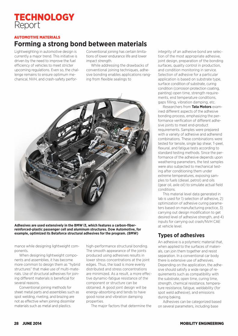
AUTOMOTIVE MATERIALS
Forming a strong bond between materialsLightweighting in automotive design is currently a major trend. This initiative is driven by the need to improve the fuel efficiency of vehicles to meet stricter upcoming regulations. Even so, the chal-lenge remains to ensure optimum me-chanical, NVH, and crash-safety perfor-
Conventional joining has certain limita-tions of lower endurance life and lower impact strength.
While addressing the drawbacks of conventional joining techniques, adhe-sive bonding enables applications rang-ing from flexible sealings to
integrity of an adhesive bond are selec-tion of the most appropriate adhesive, joint design, preparation of the bonding surfaces, quality control in production, and condition monitoring in service. Selection of adhesive for a particular application is based on substrate type, surface condition of substrate, curing condition (corrosion protection coating, painting) open time, strength require-ments, end temperature conditions, gaps filling, vibration damping, etc.
Researchers from Tata Motors exam-ined different aspects of the adhesive bonding process, emphasizing the per-formance verification of different adhe-sive joints to meet end-product requirements. Samples were prepared with a variety of adhesive and adherend combinations. These combinations were tested for tensile, single lap shear, T-peel, flexural, and fatigue tests according to standard testing methods. Since the per-formance of the adhesive depends upon weathering parameters, the test samples were also subjected to mechanical test-ing after conditioning them under extreme temperatures, exposing sam-ples to fuels (diesel, petrol) and oils (gear oil, axle oil) to simulate actual field conditions.
This material level data generated in lab is used for 1) selection of adhesive, 2) optimization of adhesive curing parame-ters based on manufacturing practice, 3) carrying out design modification to get desired level of adhesive strength, and 4) inputs for carrying out crash/NVH CAE at vehicle level.
Types of adhesivesAn adhesive is a polymeric material that, when applied to the surfaces of materi-als, can join them together and resist separation. In a conventional car body there is extensive use of adhesives. Depending on the application, the adhe-sive should satisfy a wide range of re-quirements such as compatibility with the substrate, open time, curing time, strength, chemical resistance, tempera-ture resistance, fatigue, weldability (for spot weld adhesive), and emissions during baking.
Adhesives can be categorized based on several parameters, including base
Adhesives are used extensively in the BMW i3, which features a carbon-fiber-reinforced-plastic passenger cell and aluminum structures. Dow Automotive, for example, optimized its Betaforce structural adhesives for the program. (BMW)
mance while designing lightweight com-ponents.
When designing lightweight compo-nents and assemblies, it has become more common to design them as “hybrid structures” that make use of multi-mate-rials. Use of structural adhesives for join-ing different materials is beneficial for several reasons.
Conventional joining methods for sheet metal parts and assemblies such as spot welding, riveting, and brazing are not as effective when joining dissimilar materials such as metal and plastics.
high-performance structural bonding. The smooth appearance of the joints produced using adhesives results in lower stress concentrations at the joint edges. Thus, the load is more evenly distributed and stress concentrations are minimized. As a result, a more effec-tive dynamic-fatigue resistance of the component or structure can be obtained. A good joint design will be energy-absorbing and tends to have good noise and vibration damping properties.
The major factors that determine the
MOBILITY ENGINEERING28 JUNE 2014
TECHNOLOGY Report
P140574
IMPROVE INTERIOR PACKAGE DESIGN, INCREASE VEHICLE SAFETY, AND ENSURE INTERNATIONAL COMPLIANCE WITH THE SAE H-POINT MACHINE A three-dimensional manikin that provides the physical representation of driver H-points, the H-Point Machine (HPM) is used to defi ne and measure vehicle seating accommodations. O� ering a defl ected seat rather than a free seat contour as a reference for defi ning seat space, it is a vital tool in the design of interior packages.
Available through SAE International, the HPM is used in conjunction with SAE Standard J826 and is currently referenced in various federal and international regulations including NHTSA’s FMVSS in the US and ISO standards. Utilized in testing for compliance to such regulations involving impact/crash, head restraint, or vision, it is the required safety certifi cation tool for vehicle production in many countries around the world. Additionally, those who need to locate seating reference points and torso angles as reported by manufacturers employ the SAE H-Point Machine.
SAE provides comprehensive support for the HPM including, calibration, spare parts, and maintenance. And for advance design and research applications, the HPM-II is available, which includes reformed shells for a consistent and reliable fi t in bucket seats, an articulating back for lumbar support measurement, and the ability to measure the H-point without using legs resulting in simpler installation.
View a free demonstration video at store.sae.org/ea/hpoint.htm to see how the HPM-I and the HPM-II o� er a means of obtaining passenger compartment dimensions.
SAE is an international body of engineers and practitioners dedicated to the advancement of mobility technology. Based on the fundamental of providing a neutral platform for collaboration and informed dialogue, SAE has been providing the common engineering requirements for new vehicles, advanced technologies, and applications since 1905.
SAE INTERNATIONAL+1.1.724.776.4841
www.sae.org
China +86.21.61577368
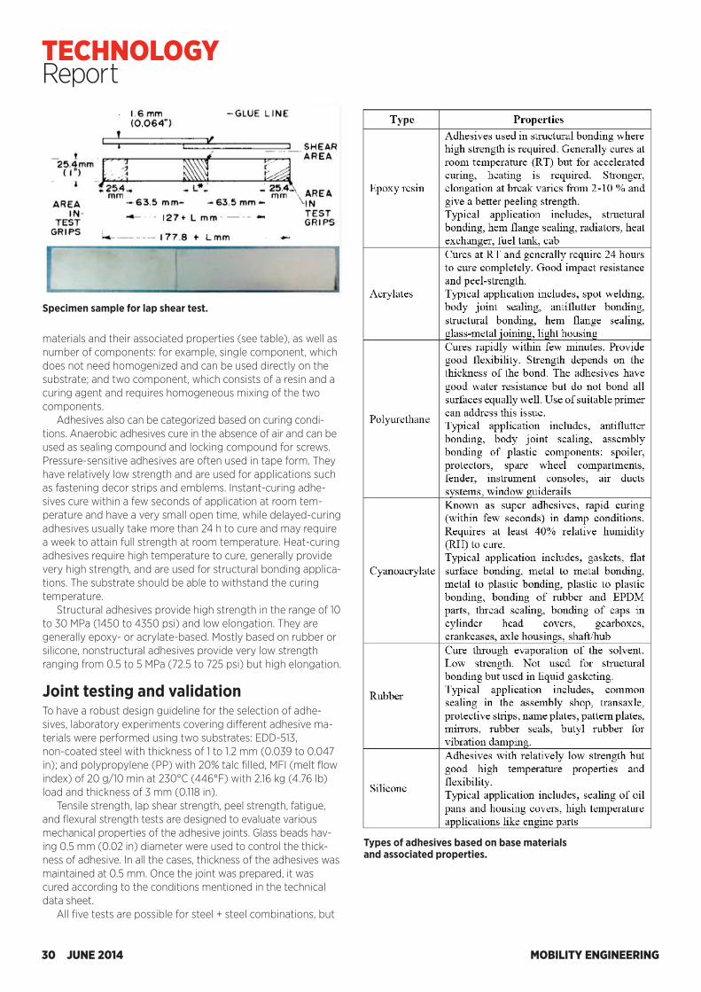
materials and their associated properties (see table), as well as number of components: for example, single component, which does not need homogenized and can be used directly on the substrate; and two component, which consists of a resin and a curing agent and requires homogeneous mixing of the two components.
Adhesives also can be categorized based on curing condi-tions. Anaerobic adhesives cure in the absence of air and can be used as sealing compound and locking compound for screws. Pressure-sensitive adhesives are often used in tape form. They have relatively low strength and are used for applications such as fastening decor strips and emblems. Instant-curing adhe-sives cure within a few seconds of application at room tem-perature and have a very small open time, while delayed-curing adhesives usually take more than 24 h to cure and may require a week to attain full strength at room temperature. Heat-curing adhesives require high temperature to cure, generally provide very high strength, and are used for structural bonding applica-tions. The substrate should be able to withstand the curing temperature.
Structural adhesives provide high strength in the range of 10 to 30 MPa (1450 to 4350 psi) and low elongation. They are generally epoxy- or acrylate-based. Mostly based on rubber or silicone, nonstructural adhesives provide very low strength ranging from 0.5 to 5 MPa (72.5 to 725 psi) but high elongation.
Joint testing and validationTo have a robust design guideline for the selection of adhe-sives, laboratory experiments covering different adhesive ma-terials were performed using two substrates: EDD-513, non-coated steel with thickness of 1 to 1.2 mm (0.039 to 0.047 in); and polypropylene (PP) with 20% talc filled, MFI (melt flow index) of 20 g/10 min at 230°C (446°F) with 2.16 kg (4.76 lb) load and thickness of 3 mm (0.118 in).
Tensile strength, lap shear strength, peel strength, fatigue, and flexural strength tests are designed to evaluate various mechanical properties of the adhesive joints. Glass beads hav-ing 0.5 mm (0.02 in) diameter were used to control the thick-ness of adhesive. In all the cases, thickness of the adhesives was maintained at 0.5 mm. Once the joint was prepared, it was cured according to the conditions mentioned in the technical data sheet.
All five tests are possible for steel + steel combinations, but
Types of adhesives based on base materials and associated properties.
Specimen sample for lap shear test.
MOBILITY ENGINEERING30 JUNE 2014
TECHNOLOGY Report
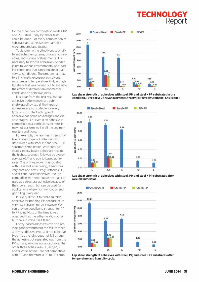
for the other two combinations—PP + PP and PP + steel—only lap shear tests could be done. For every combination of substrate and adhesive, five samples were prepared and tested.
To determine the effectiveness of dif-ferent adhesive systems, processing vari-ables, and surface pretreatments, it is necessary to expose adhesively bonded joints to various environmental and load-ing conditions that can simulate actual service conditions. The predominant fac-tors in climatic exposure are solvent, moisture, and temperature. Only a single lap shear test was carried out to evaluate the effect of different environmental conditions on adhesive joints.
It is clear from the test results that adhesive performances are sub-strate-specific—i.e., all the types of adhesives are not suitable for every type of substrate. Each type of adhesive has some advantages and dis-advantages—i.e., even if an adhesive is compatible to a particular substrate, it may not perform well in all the environ-mental conditions.
For example, the lap shear strength of five different types of adhesives was determined with steel, PP, and steel + PP substrate combination. With steel sub-strates, epoxy-based adhesives provide the highest strength, followed by cyano-acrylate (CA) and acrylic-based adhe-sives. One of the problems associated with CA is that after curing, it becomes very hard and brittle. Polyurethane (PU) and silicone-based adhesives, though compatible with steel substrates, can’t be used as a structural adhesive because of their low strength but can be used for applications where high elongation and gap filling is required.
It is very difficult to find a suitable adhesive for bonding PP because of its very low surface energy. However, CA can provide good bond strength for PP to PP joint. Most of the time it was observed that the adhesive did not fail but the substrate itself failed.
Epoxy-based adhesives can also pro-vide good strength but the failure mech-anism is adhesive type and not cohesive type—i.e., the joint does not fail through the adhesive but separated out from the PP surface, which is not acceptable. The other three adhesives—i.e., acrylic, PU, and silicone-based—are not compatible with PP, and therefore a PP to PP combi-
Lap shear strength of adhesives with steel, PP, and steel + PP substrates in dry condition. (E=epoxy; CA=cyanoacrylate; A=acrylic; PU=polyurethane; S=silicone)
Lap shear strength of adhesives with steel, PP, and steel + PP substrates after axle oil immersion.
Lap shear strength of adhesives with steel, PP, and steel + PP substrates after temperature and humidity cycle.
MOBILITY ENGINEERING JUNE 2014 31
TECHNOLOGY Report
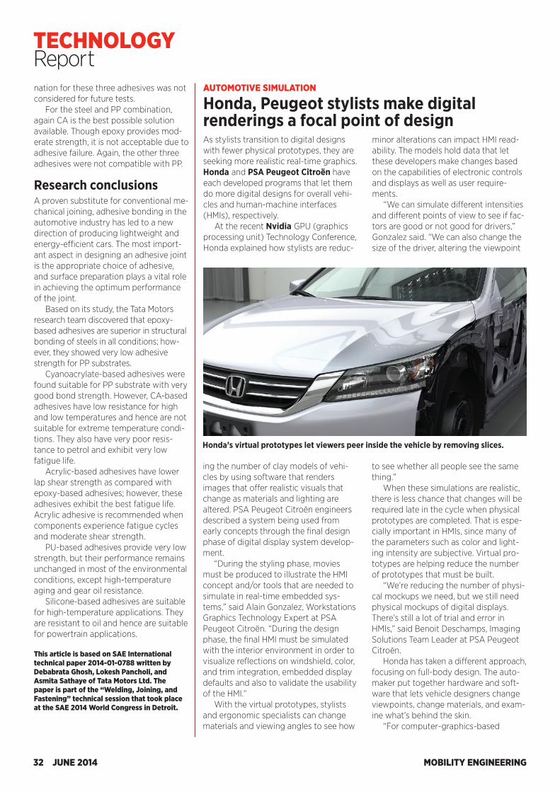
As stylists transition to digital designs with fewer physical prototypes, they are seeking more realistic real-time graphics. Honda and PSA Peugeot Citroën have each developed programs that let them do more digital designs for overall vehi-cles and human-machine interfaces (HMIs), respectively.
At the recent Nvidia GPU (graphics processing unit) Technology Conference, Honda explained how stylists are reduc-
minor alterations can impact HMI read-ability. The models hold data that let these developers make changes based on the capabilities of electronic controls and displays as well as user require-ments.
“We can simulate different intensities and different points of view to see if fac-tors are good or not good for drivers,” Gonzalez said. “We can also change the size of the driver, altering the viewpoint
AUTOMOTIVE SIMULATION
Honda, Peugeot stylists make digital renderings a focal point of design
Honda’s virtual prototypes let viewers peer inside the vehicle by removing slices.
ing the number of clay models of vehi-cles by using software that renders images that offer realistic visuals that change as materials and lighting are altered. PSA Peugeot Citroën engineers described a system being used from early concepts through the final design phase of digital display system develop-ment.
“During the styling phase, movies must be produced to illustrate the HMI concept and/or tools that are needed to simulate in real-time embedded sys-tems,” said Alain Gonzalez, Workstations Graphics Technology Expert at PSA Peugeot Citroën. “During the design phase, the final HMI must be simulated with the interior environment in order to visualize reflections on windshield, color, and trim integration, embedded display defaults and also to validate the usability of the HMI.”
With the virtual prototypes, stylists and ergonomic specialists can change materials and viewing angles to see how
to see whether all people see the same thing.”
When these simulations are realistic, there is less chance that changes will be required late in the cycle when physical prototypes are completed. That is espe-cially important in HMIs, since many of the parameters such as color and light-ing intensity are subjective. Virtual pro-totypes are helping reduce the number of prototypes that must be built.
“We’re reducing the number of physi-cal mockups we need, but we still need physical mockups of digital displays. There’s still a lot of trial and error in HMIs,” said Benoit Deschamps, Imaging Solutions Team Leader at PSA Peugeot Citroën.
Honda has taken a different approach, focusing on full-body design. The auto-maker put together hardware and soft-ware that lets vehicle designers change viewpoints, change materials, and exam-ine what’s behind the skin.
“For computer-graphics-based
nation for these three adhesives was not considered for future tests.
For the steel and PP combination, again CA is the best possible solution available. Though epoxy provides mod-erate strength, it is not acceptable due to adhesive failure. Again, the other three adhesives were not compatible with PP.
Research conclusionsA proven substitute for conventional me-chanical joining, adhesive bonding in the automotive industry has led to a new direction of producing lightweight and energy-efficient cars. The most import-ant aspect in designing an adhesive joint is the appropriate choice of adhesive, and surface preparation plays a vital role in achieving the optimum performance of the joint.
Based on its study, the Tata Motors research team discovered that epoxy-based adhesives are superior in structural bonding of steels in all conditions; how-ever, they showed very low adhesive strength for PP substrates.
Cyanoacrylate-based adhesives were found suitable for PP substrate with very good bond strength. However, CA-based adhesives have low resistance for high and low temperatures and hence are not suitable for extreme temperature condi-tions. They also have very poor resis-tance to petrol and exhibit very low fatigue life.
Acrylic-based adhesives have lower lap shear strength as compared with epoxy-based adhesives; however, these adhesives exhibit the best fatigue life. Acrylic adhesive is recommended when components experience fatigue cycles and moderate shear strength.
PU-based adhesives provide very low strength, but their performance remains unchanged in most of the environmental conditions, except high-temperature aging and gear oil resistance.
Silicone-based adhesives are suitable for high-temperature applications. They are resistant to oil and hence are suitable for powertrain applications.
This article is based on SAE International technical paper 2014-01-0788 written by Debabrata Ghosh, Lokesh Pancholi, and Asmita Sathaye of Tata Motors Ltd. The paper is part of the “Welding, Joining, and Fastening” technical session that took place at the SAE 2014 World Congress in Detroit.
MOBILITY ENGINEERING32 JUNE 2014
TECHNOLOGY Report
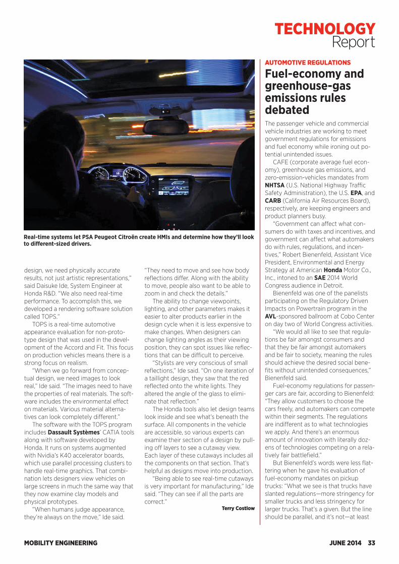
As stylists transition to digital designs with fewer physical prototypes, they are seeking more realistic real-time graphics. Honda and PSA Peugeot Citroën have each developed programs that let them do more digital designs for overall vehi-cles and human-machine interfaces (HMIs), respectively.
At the recent Nvidia GPU (graphics processing unit) Technology Conference, Honda explained how stylists are reduc-
minor alterations can impact HMI read-ability. The models hold data that let these developers make changes based on the capabilities of electronic controls and displays as well as user require-ments.
“We can simulate different intensities and different points of view to see if fac-tors are good or not good for drivers,” Gonzalez said. “We can also change the size of the driver, altering the viewpoint
AUTOMOTIVE SIMULATION
Honda, Peugeot stylists make digital renderings a focal point of design
Honda’s virtual prototypes let viewers peer inside the vehicle by removing slices.
ing the number of clay models of vehi-cles by using software that renders images that offer realistic visuals that change as materials and lighting are altered. PSA Peugeot Citroën engineers described a system being used from early concepts through the final design phase of digital display system develop-ment.
“During the styling phase, movies must be produced to illustrate the HMI concept and/or tools that are needed to simulate in real-time embedded sys-tems,” said Alain Gonzalez, Workstations Graphics Technology Expert at PSA Peugeot Citroën. “During the design phase, the final HMI must be simulated with the interior environment in order to visualize reflections on windshield, color, and trim integration, embedded display defaults and also to validate the usability of the HMI.”
With the virtual prototypes, stylists and ergonomic specialists can change materials and viewing angles to see how
to see whether all people see the same thing.”
When these simulations are realistic, there is less chance that changes will be required late in the cycle when physical prototypes are completed. That is espe-cially important in HMIs, since many of the parameters such as color and light-ing intensity are subjective. Virtual pro-totypes are helping reduce the number of prototypes that must be built.
“We’re reducing the number of physi-cal mockups we need, but we still need physical mockups of digital displays. There’s still a lot of trial and error in HMIs,” said Benoit Deschamps, Imaging Solutions Team Leader at PSA Peugeot Citroën.
Honda has taken a different approach, focusing on full-body design. The auto-maker put together hardware and soft-ware that lets vehicle designers change viewpoints, change materials, and exam-ine what’s behind the skin.
“For computer-graphics-based
nation for these three adhesives was not considered for future tests.
For the steel and PP combination, again CA is the best possible solution available. Though epoxy provides mod-erate strength, it is not acceptable due to adhesive failure. Again, the other three adhesives were not compatible with PP.
Research conclusionsA proven substitute for conventional me-chanical joining, adhesive bonding in the automotive industry has led to a new direction of producing lightweight and energy-efficient cars. The most import-ant aspect in designing an adhesive joint is the appropriate choice of adhesive, and surface preparation plays a vital role in achieving the optimum performance of the joint.
Based on its study, the Tata Motors research team discovered that epoxy-based adhesives are superior in structural bonding of steels in all conditions; how-ever, they showed very low adhesive strength for PP substrates.
Cyanoacrylate-based adhesives were found suitable for PP substrate with very good bond strength. However, CA-based adhesives have low resistance for high and low temperatures and hence are not suitable for extreme temperature condi-tions. They also have very poor resis-tance to petrol and exhibit very low fatigue life.
Acrylic-based adhesives have lower lap shear strength as compared with epoxy-based adhesives; however, these adhesives exhibit the best fatigue life. Acrylic adhesive is recommended when components experience fatigue cycles and moderate shear strength.
PU-based adhesives provide very low strength, but their performance remains unchanged in most of the environmental conditions, except high-temperature aging and gear oil resistance.
Silicone-based adhesives are suitable for high-temperature applications. They are resistant to oil and hence are suitable for powertrain applications.
This article is based on SAE International technical paper 2014-01-0788 written by Debabrata Ghosh, Lokesh Pancholi, and Asmita Sathaye of Tata Motors Ltd. The paper is part of the “Welding, Joining, and Fastening” technical session that took place at the SAE 2014 World Congress in Detroit.
MOBILITY ENGINEERING32 JUNE 2014
TECHNOLOGY Report
design, we need physically accurate results, not just artistic representations,” said Daisuke Ide, System Engineer at Honda R&D. “We also need real-time performance. To accomplish this, we developed a rendering software solution called TOPS.”
TOPS is a real-time automotive appearance evaluation for non-proto-type design that was used in the devel-opment of the Accord and Fit. This focus on production vehicles means there is a strong focus on realism.
“When we go forward from concep-tual design, we need images to look real,” Ide said. “The images need to have the properties of real materials. The soft-ware includes the environmental effect on materials. Various material alterna-tives can look completely different.”
The software with the TOPS program includes Dassault Systèmes’ CATIA tools along with software developed by Honda. It runs on systems augmented with Nvidia’s K40 accelerator boards, which use parallel processing clusters to handle real-time graphics. That combi-nation lets designers view vehicles on large screens in much the same way that they now examine clay models and physical prototypes.
“When humans judge appearance, they’re always on the move,” Ide said.
“They need to move and see how body reflections differ. Along with the ability to move, people also want to be able to zoom in and check the details.”
The ability to change viewpoints, lighting, and other parameters makes it easier to alter products earlier in the design cycle when it is less expensive to make changes. When designers can change lighting angles as their viewing position, they can spot issues like reflec-tions that can be difficult to perceive.
“Stylists are very conscious of small reflections,” Ide said. “On one iteration of a taillight design, they saw that the red reflected onto the white lights. They altered the angle of the glass to elimi-nate that reflection.”
The Honda tools also let design teams look inside and see what’s beneath the surface. All components in the vehicle are accessible, so various experts can examine their section of a design by pull-ing off layers to see a cutaway view. Each layer of these cutaways includes all the components on that section. That’s helpful as designs move into production.
“Being able to see real-time cutaways is very important for manufacturing,” Ide said. “They can see if all the parts are correct.”
Terry Costlow
Real-time systems let PSA Peugeot Citroën create HMIs and determine how they’ll look to different-sized drivers.
AUTOMOTIVE REGULATIONS
Fuel-economy and greenhouse-gas emissions rules debatedThe passenger vehicle and commercial vehicle industries are working to meet government regulations for emissions and fuel economy while ironing out po-tential unintended issues.
CAFE (corporate average fuel econ-omy), greenhouse gas emissions, and zero-emission-vehicles mandates from NHTSA (U.S. National Highway Traffic Safety Administration), the U.S. EPA, and CARB (California Air Resources Board), respectively, are keeping engineers and product planners busy.
“Government can affect what con-sumers do with taxes and incentives, and government can affect what automakers do with rules, regulations, and incen-tives,” Robert Bienenfeld, Assistant Vice President, Environmental and Energy Strategy at American Honda Motor Co., Inc., intoned to an SAE 2014 World Congress audience in Detroit.
Bienenfeld was one of the panelists participating on the Regulatory Driven Impacts on Powertrain program in the AVL-sponsored ballroom at Cobo Center on day two of World Congress activities.
“We would all like to see that regula-tions be fair amongst consumers and that they be fair amongst automakers and be fair to society, meaning the rules should achieve the desired social bene-fits without unintended consequences,” Bienenfeld said.
Fuel-economy regulations for passen-ger cars are fair, according to Bienenfeld: “They allow customers to choose the cars freely, and automakers can compete within their segments. The regulations are indifferent as to what technologies we apply. And there’s an enormous amount of innovation with literally doz-ens of technologies competing on a rela-tively fair battlefield.”
But Bienenfeld’s words were less flat-tering when he gave his evaluation of fuel-economy mandates on pickup trucks: “What we see is that trucks have slanted regulations—more stringency for smaller trucks and less stringency for larger trucks. That’s a given. But the line should be parallel, and it’s not—at least
MOBILITY ENGINEERING JUNE 2014 33
TECHNOLOGY Report
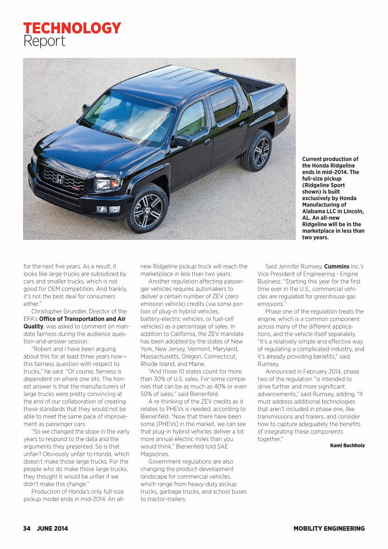
for the next five years. As a result, it looks like large trucks are subsidized by cars and smaller trucks, which is not good for OEM competition. And frankly, it’s not the best deal for consumers either.”
Christopher Grundler, Director of the EPA’s Office of Transportation and Air Quality, was asked to comment on man-date fairness during the audience ques-tion-and-answer session.
“Robert and I have been arguing about this for at least three years now—this fairness question with respect to trucks,” he said. “Of course, fairness is dependent on where one sits. The hon-est answer is that the manufacturers of large trucks were pretty convincing at the end of our collaboration of creating these standards that they would not be able to meet the same pace of improve-ment as passenger cars.
“So we changed the slope in the early years to respond to the data and the arguments they presented. So is that unfair? Obviously unfair to Honda, which doesn’t make those large trucks. For the people who do make those large trucks, they thought it would be unfair if we didn’t make this change.”
Production of Honda’s only full-size pickup model ends in mid-2014. An all-
Said Jennifer Rumsey, Cummins Inc.’s Vice President of Engineering - Engine Business: “Starting this year for the first time ever in the U.S., commercial vehi-cles are regulated for greenhouse gas emissions.”
Phase one of the regulation treats the engine, which is a common component across many of the different applica-tions, and the vehicle itself separately. “It’s a relatively simple and effective way of regulating a complicated industry, and it’s already providing benefits,” said Rumsey.
Announced in February 2014, phase two of the regulation “is intended to drive further and more significant advancements,” said Rumsey, adding, “It must address additional technologies that aren’t included in phase one, like transmissions and trailers, and consider how to capture adequately the benefits of integrating these components together.”
Kami Buchholz
new Ridgeline pickup truck will reach the marketplace in less than two years.
Another regulation affecting passen-ger vehicles requires automakers to deliver a certain number of ZEV (zero emission vehicle) credits (via some por-tion of plug-in hybrid vehicles, battery-electric vehicles, or fuel-cell vehicles) as a percentage of sales. In addition to California, the ZEV mandate has been adopted by the states of New York, New Jersey, Vermont, Maryland, Massachusetts, Oregon, Connecticut, Rhode Island, and Maine.
“And those 10 states count for more than 30% of U.S. sales. For some compa-nies that can be as much as 40% or even 50% of sales,” said Bienenfeld.
A re-thinking of the ZEV credits as it relates to PHEVs is needed, according to Bienenfeld. “Now that there have been some [PHEVs] in the market, we can see that plug-in hybrid vehicles deliver a lot more annual electric miles than you would think,” Bienenfeld told SAE Magazines.
Government regulations are also changing the product-development landscape for commercial vehicles, which range from heavy-duty pickup trucks, garbage trucks, and school buses to tractor-trailers.
Current production of the Honda Ridgeline ends in mid-2014. The full-size pickup (Ridgeline Sport shown) is built exclusively by Honda Manufacturing of Alabama LLC in Lincoln, AL. An all-new Ridgeline will be in the marketplace in less than two years.
MOBILITY ENGINEERING34 JUNE 2014
TECHNOLOGY Report
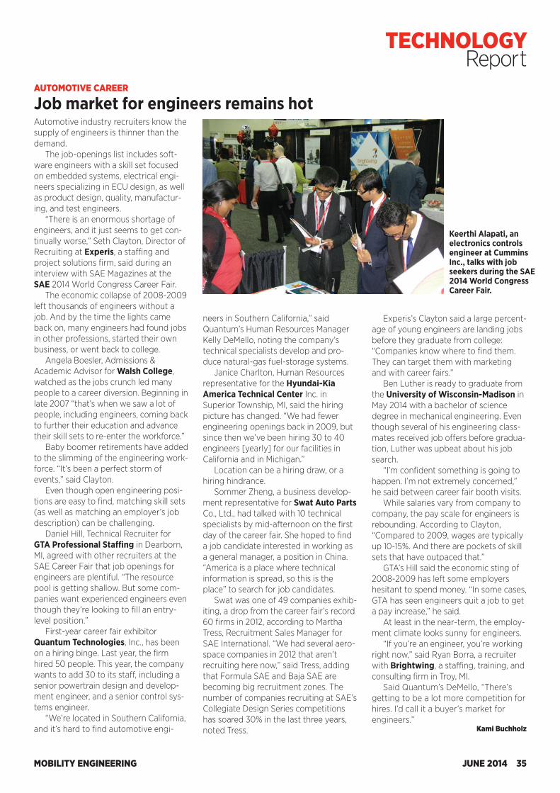
for the next five years. As a result, it looks like large trucks are subsidized by cars and smaller trucks, which is not good for OEM competition. And frankly, it’s not the best deal for consumers either.”
Christopher Grundler, Director of the EPA’s Office of Transportation and Air Quality, was asked to comment on man-date fairness during the audience ques-tion-and-answer session.
“Robert and I have been arguing about this for at least three years now—this fairness question with respect to trucks,” he said. “Of course, fairness is dependent on where one sits. The hon-est answer is that the manufacturers of large trucks were pretty convincing at the end of our collaboration of creating these standards that they would not be able to meet the same pace of improve-ment as passenger cars.
“So we changed the slope in the early years to respond to the data and the arguments they presented. So is that unfair? Obviously unfair to Honda, which doesn’t make those large trucks. For the people who do make those large trucks, they thought it would be unfair if we didn’t make this change.”
Production of Honda’s only full-size pickup model ends in mid-2014. An all-
Said Jennifer Rumsey, Cummins Inc.’s Vice President of Engineering - Engine Business: “Starting this year for the first time ever in the U.S., commercial vehi-cles are regulated for greenhouse gas emissions.”
Phase one of the regulation treats the engine, which is a common component across many of the different applica-tions, and the vehicle itself separately. “It’s a relatively simple and effective way of regulating a complicated industry, and it’s already providing benefits,” said Rumsey.
Announced in February 2014, phase two of the regulation “is intended to drive further and more significant advancements,” said Rumsey, adding, “It must address additional technologies that aren’t included in phase one, like transmissions and trailers, and consider how to capture adequately the benefits of integrating these components together.”
Kami Buchholz
new Ridgeline pickup truck will reach the marketplace in less than two years.
Another regulation affecting passen-ger vehicles requires automakers to deliver a certain number of ZEV (zero emission vehicle) credits (via some por-tion of plug-in hybrid vehicles, battery-electric vehicles, or fuel-cell vehicles) as a percentage of sales. In addition to California, the ZEV mandate has been adopted by the states of New York, New Jersey, Vermont, Maryland, Massachusetts, Oregon, Connecticut, Rhode Island, and Maine.
“And those 10 states count for more than 30% of U.S. sales. For some compa-nies that can be as much as 40% or even 50% of sales,” said Bienenfeld.
A re-thinking of the ZEV credits as it relates to PHEVs is needed, according to Bienenfeld. “Now that there have been some [PHEVs] in the market, we can see that plug-in hybrid vehicles deliver a lot more annual electric miles than you would think,” Bienenfeld told SAE Magazines.
Government regulations are also changing the product-development landscape for commercial vehicles, which range from heavy-duty pickup trucks, garbage trucks, and school buses to tractor-trailers.
Current production of the Honda Ridgeline ends in mid-2014. The full-size pickup (Ridgeline Sport shown) is built exclusively by Honda Manufacturing of Alabama LLC in Lincoln, AL. An all-new Ridgeline will be in the marketplace in less than two years.
MOBILITY ENGINEERING34 JUNE 2014
TECHNOLOGY Report
Automotive industry recruiters know the supply of engineers is thinner than the demand.
The job-openings list includes soft-ware engineers with a skill set focused on embedded systems, electrical engi-neers specializing in ECU design, as well as product design, quality, manufactur-ing, and test engineers.
“There is an enormous shortage of engineers, and it just seems to get con-tinually worse,” Seth Clayton, Director of Recruiting at Experis, a staffing and project solutions firm, said during an interview with SAE Magazines at the SAE 2014 World Congress Career Fair.
The economic collapse of 2008-2009 left thousands of engineers without a job. And by the time the lights came back on, many engineers had found jobs in other professions, started their own business, or went back to college.
Angela Boesler, Admissions & Academic Advisor for Walsh College, watched as the jobs crunch led many people to a career diversion. Beginning in late 2007 “that’s when we saw a lot of people, including engineers, coming back to further their education and advance their skill sets to re-enter the workforce.”
Baby boomer retirements have added to the slimming of the engineering work-force. “It’s been a perfect storm of events,” said Clayton.
Even though open engineering posi-tions are easy to find, matching skill sets (as well as matching an employer’s job description) can be challenging.
Daniel Hill, Technical Recruiter for GTA Professional Staffing in Dearborn, MI, agreed with other recruiters at the SAE Career Fair that job openings for engineers are plentiful. “The resource pool is getting shallow. But some com-panies want experienced engineers even though they’re looking to fill an entry-level position.”
First-year career fair exhibitor Quantum Technologies, Inc., has been on a hiring binge. Last year, the firm hired 50 people. This year, the company wants to add 30 to its staff, including a senior powertrain design and develop-ment engineer, and a senior control sys-tems engineer.
“We’re located in Southern California, and it’s hard to find automotive engi-
Experis’s Clayton said a large percent-age of young engineers are landing jobs before they graduate from college: “Companies know where to find them. They can target them with marketing and with career fairs.”
Ben Luther is ready to graduate from the University of Wisconsin-Madison in May 2014 with a bachelor of science degree in mechanical engineering. Even though several of his engineering class-mates received job offers before gradua-tion, Luther was upbeat about his job search.
“I’m confident something is going to happen. I’m not extremely concerned,” he said between career fair booth visits.
While salaries vary from company to company, the pay scale for engineers is rebounding. According to Clayton, “Compared to 2009, wages are typically up 10-15%. And there are pockets of skill sets that have outpaced that.”
GTA’s Hill said the economic sting of 2008-2009 has left some employers hesitant to spend money. “In some cases, GTA has seen engineers quit a job to get a pay increase,” he said.
At least in the near-term, the employ-ment climate looks sunny for engineers.
“If you’re an engineer, you’re working right now,” said Ryan Borra, a recruiter with Brightwing, a staffing, training, and consulting firm in Troy, MI.
Said Quantum’s DeMello, “There’s getting to be a lot more competition for hires. I’d call it a buyer’s market for engineers.”
Kami Buchholz
AUTOMOTIVE CAREER
Job market for engineers remains hot
neers in Southern California,” said Quantum’s Human Resources Manager Kelly DeMello, noting the company’s technical specialists develop and pro-duce natural-gas fuel-storage systems.
Janice Charlton, Human Resources representative for the Hyundai-Kia America Technical Center Inc. in Superior Township, MI, said the hiring picture has changed. “We had fewer engineering openings back in 2009, but since then we’ve been hiring 30 to 40 engineers [yearly] for our facilities in California and in Michigan.”
Location can be a hiring draw, or a hiring hindrance.
Sommer Zheng, a business develop-ment representative for Swat Auto Parts Co., Ltd., had talked with 10 technical specialists by mid-afternoon on the first day of the career fair. She hoped to find a job candidate interested in working as a general manager, a position in China. “America is a place where technical information is spread, so this is the place” to search for job candidates.
Swat was one of 49 companies exhib-iting, a drop from the career fair’s record 60 firms in 2012, according to Martha Tress, Recruitment Sales Manager for SAE International. “We had several aero-space companies in 2012 that aren’t recruiting here now,” said Tress, adding that Formula SAE and Baja SAE are becoming big recruitment zones. The number of companies recruiting at SAE’s Collegiate Design Series competitions has soared 30% in the last three years, noted Tress.
Keerthi Alapati, an electronics controls engineer at Cummins Inc., talks with job seekers during the SAE 2014 World Congress Career Fair.
MOBILITY ENGINEERING JUNE 2014 35
TECHNOLOGY Report
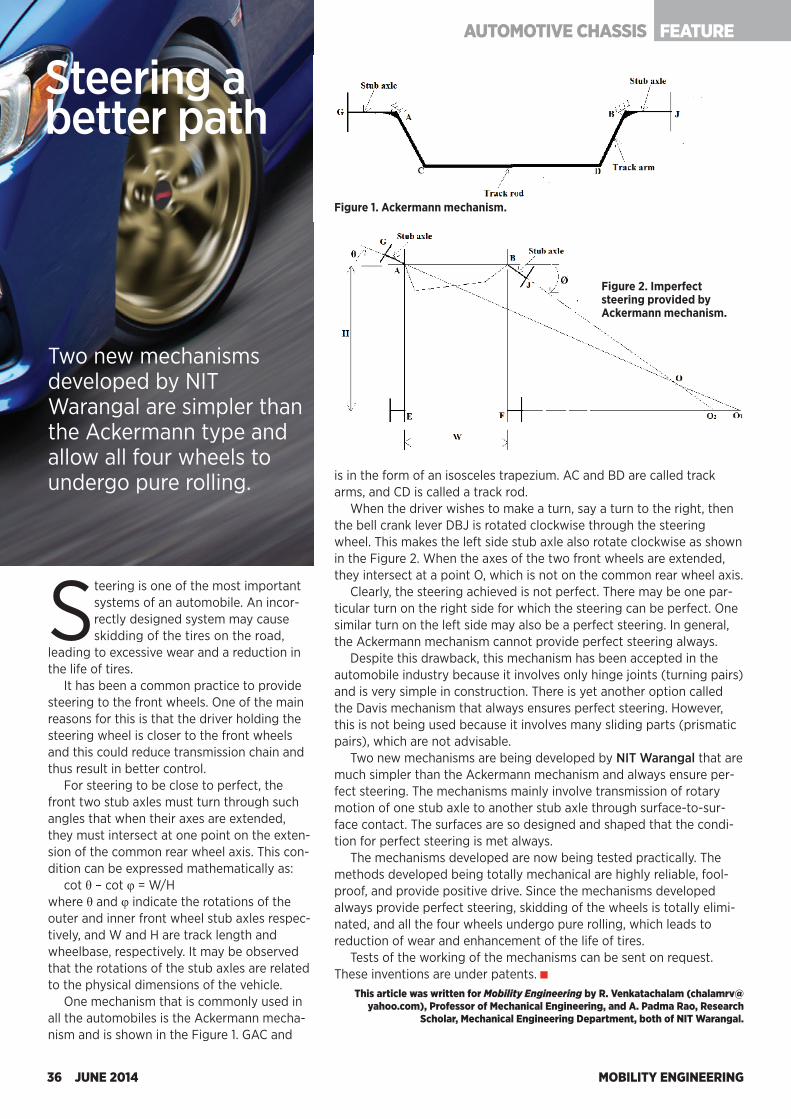
MOBILITY ENGINEERING36 JUNE 2014
Steering is one of the most important systems of an automobile. An incor-rectly designed system may cause skidding of the tires on the road,
leading to excessive wear and a reduction in the life of tires.
It has been a common practice to provide steering to the front wheels. One of the main reasons for this is that the driver holding the steering wheel is closer to the front wheels and this could reduce transmission chain and thus result in better control.
For steering to be close to perfect, the front two stub axles must turn through such angles that when their axes are extended, they must intersect at one point on the exten-sion of the common rear wheel axis. This con-dition can be expressed mathematically as:
cot θ – cot φ = W/Hwhere θ and φ indicate the rotations of the outer and inner front wheel stub axles respec-tively, and W and H are track length and wheelbase, respectively. It may be observed that the rotations of the stub axles are related to the physical dimensions of the vehicle.
One mechanism that is commonly used in all the automobiles is the Ackermann mecha-nism and is shown in the Figure 1. GAC and
JBD are called bell crank levers, while GA and BJ are stub axles of front wheels. The bell crank levers are hinged to the chassis of the vehicle at A and B. The actual mechanism is a four link mechanism ABDC, which is in the form of an isosceles trapezium. AC and BD are called track arms, and CD is called a track rod.
When the driver wishes to make a turn, say a turn to the right, then the bell crank lever DBJ is rotated clockwise through the steering wheel. This makes the left side stub axle also rotate clockwise as shown in the Figure 2. When the axes of the two front wheels are extended, they intersect at a point O, which is not on the common rear wheel axis.
Clearly, the steering achieved is not perfect. There may be one par-ticular turn on the right side for which the steering can be perfect. One similar turn on the left side may also be a perfect steering. In general, the Ackermann mechanism cannot provide perfect steering always.
Despite this drawback, this mechanism has been accepted in the automobile industry because it involves only hinge joints (turning pairs) and is very simple in construction. There is yet another option called the Davis mechanism that always ensures perfect steering. However, this is not being used because it involves many sliding parts (prismatic pairs), which are not advisable.
Two new mechanisms are being developed by NIT Warangal that are much simpler than the Ackermann mechanism and always ensure per-fect steering. The mechanisms mainly involve transmission of rotary motion of one stub axle to another stub axle through surface-to-sur-face contact. The surfaces are so designed and shaped that the condi-tion for perfect steering is met always.
The mechanisms developed are now being tested practically. The methods developed being totally mechanical are highly reliable, fool-proof, and provide positive drive. Since the mechanisms developed always provide perfect steering, skidding of the wheels is totally elimi-nated, and all the four wheels undergo pure rolling, which leads to reduction of wear and enhancement of the life of tires.
Tests of the working of the mechanisms can be sent on request. These inventions are under patents.
This article was written for Mobility Engineering by R. Venkatachalam ([email protected]), Professor of Mechanical Engineering, and A. Padma Rao, Research
Scholar, Mechanical Engineering Department, both of NIT Warangal.
Steering a better path
Two new mechanisms developed by NIT Warangal are simpler than the Ackermann type and allow all four wheels to undergo pure rolling.
Figure 1. Ackermann mechanism.
Figure 2. Imperfect steering provided by Ackermann mechanism.
FEATUREAUTOMOTIVE CHASSIS
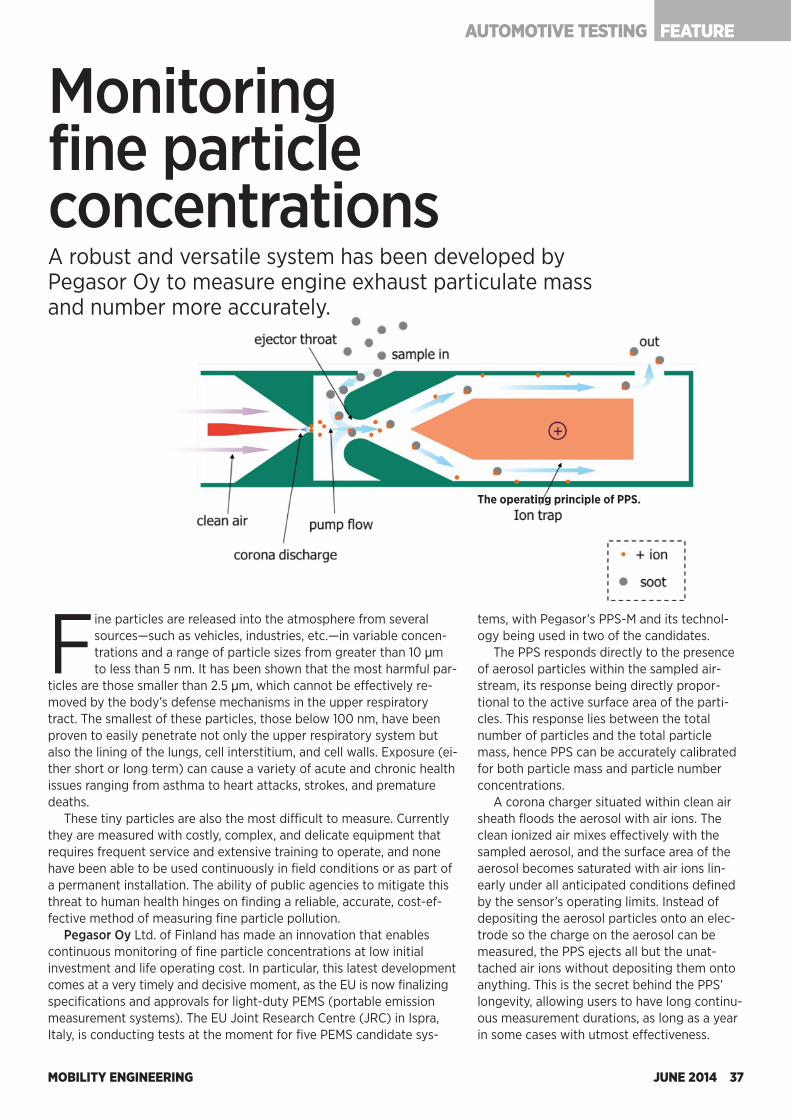
MOBILITY ENGINEERING JUNE 2014 37
FEATUREAUTOMOTIVE TESTING
Fine particles are released into the atmosphere from several sources—such as vehicles, industries, etc.—in variable concen-trations and a range of particle sizes from greater than 10 µm to less than 5 nm. It has been shown that the most harmful par-
ticles are those smaller than 2.5 µm, which cannot be effectively re-moved by the body’s defense mechanisms in the upper respiratory tract. The smallest of these particles, those below 100 nm, have been proven to easily penetrate not only the upper respiratory system but also the lining of the lungs, cell interstitium, and cell walls. Exposure (ei-ther short or long term) can cause a variety of acute and chronic health issues ranging from asthma to heart attacks, strokes, and premature deaths.
These tiny particles are also the most difficult to measure. Currently they are measured with costly, complex, and delicate equipment that requires frequent service and extensive training to operate, and none have been able to be used continuously in field conditions or as part of a permanent installation. The ability of public agencies to mitigate this threat to human health hinges on finding a reliable, accurate, cost-ef-fective method of measuring fine particle pollution.
Pegasor Oy Ltd. of Finland has made an innovation that enables continuous monitoring of fine particle concentrations at low initial investment and life operating cost. In particular, this latest development comes at a very timely and decisive moment, as the EU is now finalizing specifications and approvals for light-duty PEMS (portable emission measurement systems). The EU Joint Research Centre (JRC) in Ispra, Italy, is conducting tests at the moment for five PEMS candidate sys-
Monitoring fine particle concentrationsA robust and versatile system has been developed by Pegasor Oy to measure engine exhaust particulate mass and number more accurately.
tems, with Pegasor’s PPS-M and its technol-ogy being used in two of the candidates.
The PPS responds directly to the presence of aerosol particles within the sampled air-stream, its response being directly propor-tional to the active surface area of the parti-cles. This response lies between the total number of particles and the total particle mass, hence PPS can be accurately calibrated for both particle mass and particle number concentrations.
A corona charger situated within clean air sheath floods the aerosol with air ions. The clean ionized air mixes effectively with the sampled aerosol, and the surface area of the aerosol becomes saturated with air ions lin-early under all anticipated conditions defined by the sensor’s operating limits. Instead of depositing the aerosol particles onto an elec-trode so the charge on the aerosol can be measured, the PPS ejects all but the unat-tached air ions without depositing them onto anything. This is the secret behind the PPS’ longevity, allowing users to have long continu-ous measurement durations, as long as a year in some cases with utmost effectiveness.
The operating principle of PPS.
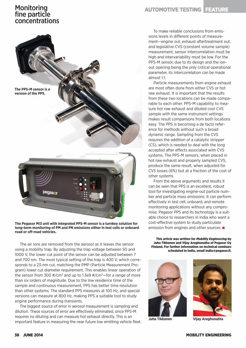
The air ions are removed from the aerosol as it leaves the sensor using a mobility trap. By adjusting the trap voltage between 50 and 1000 V, the lower cut point of the sensor can be adjusted between 7 and 700 nm. The most typical setting of the trap is 400 V, which corre-sponds to a 23-nm cut, matching the PMP (Particle Measurement Pro-gram) lower cut diameter requirement. This enables linear operation of the sensor from 300 #/cm3 and up to 1.3e9 #/cm3—for a range of more than six orders of magnitude. Due to the low residence time of the sample and continuous measurement, PPS has better time resolution than other systems. The standard PPS measures at 100 Hz, and special versions can measure at 800 Hz, making PPS a suitable tool to study engine performance during transients.
The biggest source of error in aerosol measurement is sampling and dilution. These sources of error are effectively eliminated, since PPS-M requires no diluting and can measure hot exhaust directly. This is an important feature in measuring the near future low emitting vehicle fleet.
Monitoring fine particle concentrations
MOBILITY ENGINEERING38 JUNE 2014
The PPS-M sensor is a version of the PPS.
To make reliable conclusions from emis-sions levels in different points of measure-ment—engine out, exhaust aftertreatment out, and legislative CVS (constant volume sample) measurement, sensor intercorrelation must be high and intervariability must be low. For the PPS-M sensor, due to its design and the ion-out opening being the only critical operational parameter, its intercorrelation can be made almost 1:1.
Particle measurements from engine exhaust are most often done from either CVS or hot raw exhaust. It is important that the results from these two locations can be made compa-rable to each other. PPS-M capability to mea-sure hot raw exhaust and diluted cool CVS sample with the same instrument settings makes result comparisons from both locations easy. The PPS is becoming a de facto refer-ence for methods without such a broad dynamic range. Sampling from the CVS requires the addition of a catalytic stripper (CS), which is needed to deal with the long accepted after effects associated with CVS systems. The PPS-M sensors, when placed in hot raw exhaust and properly sampled CVS, produce the same result, when adjusted for CVS losses (6%) but at a fraction of the cost of other systems.
From the above arguments and results it can be seen that PPS is an excellent, robust tool for investigating engine-out particle num-ber and particle mass emissions. It can perform effectively in test cell, onboard, and remote monitoring applications without any compro-mise. Pegasor PPS and its technology is a suit-able choice to researchers in India who want a cost-effective system to study particulate emission from engines and other sources.
This article was written for Mobility Engineering by Juha Tikkanen and Vijay Araghunatha of Pegasor Oy
Finland. For further information on technical seminars scheduled in India, email [email protected].
The Pegasor Mi3 unit with integrated PPS-M sensor is a turnkey solution for long-term monitoring of PM and PN emissions either in test cells or onboard road or off-road vehicles.
Juha Tikkanen Vijay Araghunatha
FEATUREAUTOMOTIVE TESTING
MOBILITY ENGINEERING JUNE 2014 39
FEATURE AUTOMOTIVE MOTORSPORTS
MOBILITY ENGINEERING39 JUNE 2014
New turbocharged hybrid-electric power units and revised aerodynamics may scramble the familiar order in Formula One for 2014.
by Dan Carney
New rulesshuffle the F1 deck
With the MP4-29, McLaren Mercedes aims to regain winning form in 2014. Shown here (left to right) are main drivers Kevin Magnussen and Jenson Button, and reserve driver Stoffel Vandoorne.
This season will see an almost entirely new slate of rules for Formula One that effectively make it a different series. The cars are changed aerodynamically and have dramatically different power sources. Stiff limitations on track testing, wind tunnel
testing, and even CFD modeling aim to limit costs and reduce the advan-tage bigger-budget teams hold over smaller teams.
Championship points will be allocated differently (double points in the last race), and there are two new circuits on the schedule.
The scope of the change will, itself, affect the course of the season, as teams encounter reliability problems stemming from the newness of their equipment, and as relative performance changes as some teams make bigger gains than others from one race to the next.
Ferrari Technical Director James Allison ruminated on what the changes have meant for Formula One engineering staffs and what they will mean to competitors this year.
“2014 sees us, for the first time in many years, have free develop-ment of the engine from a clean sheet of paper,” he said. “For sure that’s going to bring a level of variation of power between the various engine manufacturers. It makes the engine a much more important competitive factor in 2014 than it has been in recent years.”
FEATURE AUTOMOTIVE MOTORSPORTS
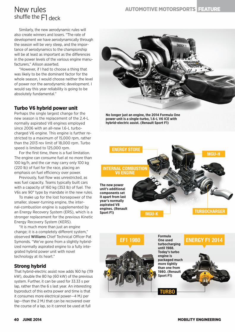
MOBILITY ENGINEERING40 JUNE 2014
Similarly, the new aerodynamic rules will also create winners and losers. “The rate of development we have aerodynamically through the season will be very steep, and the impor-tance of aerodynamics to the championship will be at least as important as the differences in the power levels of the various engine manu-facturers,” Allison asserted.
“However, if I had to choose a thing that was likely to be the dominant factor for the whole season, I would choose neither the level of power nor the aerodynamic development. I would say this year reliability is going to be absolutely fundamental.”
Turbo V6 hybrid power unitPerhaps the single largest change for the new season is the replacement of the 2.4-L normally aspirated V8 engines employed since 2006 with an all-new 1.6-L turbo-charged V6 engine. This engine is further re-stricted to a maximum of 15,000 rpm, rather than the 2013 rev limit of 18,000 rpm. Turbo speed is limited to 125,000 rpm.
For the first time, there is a fuel limitation. The engine can consume fuel at no more than 100 kg/h, and the car may carry only 100 kg (220 lb) of fuel for the race, placing an emphasis on fuel efficiency over power.
Previously, fuel flow was unrestricted, as was fuel capacity. Teams typically built cars with a capacity of 160 kg (353 lb) of fuel. The V6s are 90° type by mandate in the new rules.
To make up for the lost horsepower of the smaller, slower-turning engine, the inter-nal-combustion engine is supplemented by an Energy Recovery System (ERS), which is a stronger replacement for the previous Kinetic Energy Recovery System (KERS).
“It is much more than just an engine change; it is a completely different system,” observed Williams Chief Technical Officer Pat Symonds. “We’ve gone from a slightly hybrid-ized normally aspirated engine to a fully inte-grated hybrid power unit with novel technology at its heart.”
Strong hybridThat hybrid-electric assist now adds 160 hp (119 kW), double the 80 hp (60 kW) of the previous system. Further, it can be used for 33.33 s per lap, rather than the 6 s last year. An interesting byproduct of this extra power and time is that it consumes more electrical power—4 MJ per lap—than the 2 MJ that can be recovered over the course of a lap, so it cannot be used at full
Formula One used turbocharging until 1988. Today’s turbo engine is packaged much more tightly than one from 1980. (Renault Sport F1)
No longer just an engine, the 2014 Formula One power unit is a single-turbo, 1.6-L V6 ICE with hybrid-electric assist. (Renault Sport F1)
The new power unit’s additional components set it apart from last year’s normally aspirated V8 engines. (Renault Sport F1)
New rulesshuffle the F1 deck
FEATURE AUTOMOTIVE MOTORSPORTS FEATURE
SAE INTERNATIONAL BRINGING LEARNING TO YOU.
SAE International o� ers you education and training resources in the areas that are shaping the mobility industry and your career. Instructor led programs taught by respected and expert industry professionals.
• Online courses that supply the technical content you expect without the expense of travel or time away from your o� ce
• Customized onsite training designed for your organization’s specifi c needs
Visit training.sae.org to view all SAE International professional development opportunities, schedules and course information.
P140565
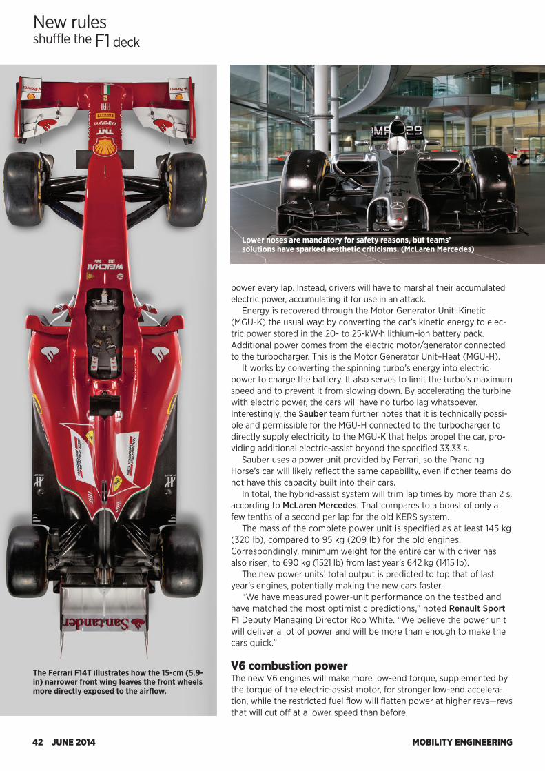
MOBILITY ENGINEERING42 JUNE 2014
power every lap. Instead, drivers will have to marshal their accumulated electric power, accumulating it for use in an attack.
Energy is recovered through the Motor Generator Unit–Kinetic (MGU-K) the usual way: by converting the car’s kinetic energy to elec-tric power stored in the 20- to 25-kW·h lithium-ion battery pack. Additional power comes from the electric motor/generator connected to the turbocharger. This is the Motor Generator Unit–Heat (MGU-H).
It works by converting the spinning turbo’s energy into electric power to charge the battery. It also serves to limit the turbo’s maximum speed and to prevent it from slowing down. By accelerating the turbine with electric power, the cars will have no turbo lag whatsoever. Interestingly, the Sauber team further notes that it is technically possi-ble and permissible for the MGU-H connected to the turbocharger to directly supply electricity to the MGU-K that helps propel the car, pro-viding additional electric-assist beyond the specified 33.33 s.
Sauber uses a power unit provided by Ferrari, so the Prancing Horse’s car will likely reflect the same capability, even if other teams do not have this capacity built into their cars.
In total, the hybrid-assist system will trim lap times by more than 2 s, according to McLaren Mercedes. That compares to a boost of only a few tenths of a second per lap for the old KERS system.
The mass of the complete power unit is specified as at least 145 kg (320 lb), compared to 95 kg (209 lb) for the old engines. Correspondingly, minimum weight for the entire car with driver has also risen, to 690 kg (1521 lb) from last year’s 642 kg (1415 lb).
The new power units’ total output is predicted to top that of last year’s engines, potentially making the new cars faster.
“We have measured power-unit performance on the testbed and have matched the most optimistic predictions,” noted Renault Sport F1 Deputy Managing Director Rob White. “We believe the power unit will deliver a lot of power and will be more than enough to make the cars quick.” V6 combustion powerThe new V6 engines will make more low-end torque, supplemented by the torque of the electric-assist motor, for stronger low-end accelera-tion, while the restricted fuel flow will flatten power at higher revs—revs that will cut off at a lower speed than before.
New rulesshuffle the F1 deck
The Ferrari F14T illustrates how the 15-cm (5.9-in) narrower front wing leaves the front wheels more directly exposed to the airflow.
Lower noses are mandatory for safety reasons, but teams’ solutions have sparked aesthetic criticisms. (McLaren Mercedes)
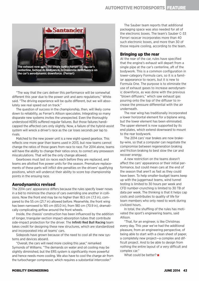
MOBILITY ENGINEERING JUNE 2014 43
FEATURE AUTOMOTIVE MOTORSPORTS
The exhaust now exits the single turbocharger on the car’s centerline, behind its bodywork, to minimize its influence on the car’s aerodynamic downforce. (Ferrari)
“The way that the cars deliver this performance will be somewhat different this year due to the power unit and aero regulations,” White said. “The driving experience will be quite different, but we will abso-lutely see real speed out on track.”
The question of success in the championship, then, will likely come down to reliability, as Ferrari’s Allison speculates. Integrating so many disparate new systems invites the unexpected. Even the thoroughly understood KERS suffered regular failures. But those failures handi-capped the affected cars only slightly. Now, a failure of the hybrid-assist system will wreck a driver’s race as the car loses seconds per lap to rivals.
Matched to the new power unit is a new eight-speed gearbox. This reflects one more gear than teams used in 2013, but now teams cannot change the ratios of those gears from race to race. For 2014 alone, teams will have the ability to change their ratios once, to correct any preseason miscalculations. That will be the only change allowed.
Gearboxes must last six races each before they are replaced, and teams are allotted five power units for the season. Premature replace-ments of these parts will inflict dire penalties on the drivers’ qualifying positions, which will undercut their ability to score top championship points in the ensuing race. Aerodynamics revisedThe 2014 cars’ appearance differs because the rules specify lower noses in a bid to minimize the chance of cars overriding one another in colli-sions. Now the front end may be no higher than 18.5 cm (7.3 in), com-pared to the 55 cm (21.7 in) allowed before. Meanwhile, the front wing has been narrowed to 165 cm (65.0 in), from 180 cm (70.9 in), dramati-cally complicating airflow around the front wheels.
Inside, the chassis’ construction has been influenced by the addition of longer, triangular-section impact-absorption tubes that contribute side-impact protection for the driver. The Infiniti Red Bull Racing team takes credit for designing these new structures, which are standardized and incorporated into all teams’ cars.
Sidepods have grown because of the need to cool all the new sys-tems and devices aboard.
“Overall, the cars will need more cooling this year,” remarked Symonds of Williams. “The demands on water and oil cooling may be slightly diminished, but the ERS system is significantly more powerful and hence needs more cooling. We also have to cool the charge air from the turbocharger compressor, which requires a substantial intercooler.”
The Sauber team reports that additional packaging space was also needed for all of the electronic boxes. The team’s Sauber C-33 Ferrari racecar incorporates more than 40 such electronic boxes, and more than 30 of those require cooling, according to the team.
Bringing up the rearAt the rear of the car, rules have specified that the engine’s exhaust will depart from a single pipe at the car’s centerline, aft of the bodywork. This is a common configuration in lower-category Formula cars, so it is a famil-iar appearance to racers, but it is new to Formula One. The purpose is to eliminate the use of exhaust gases to increase aerodynam-ic downforce, as was done with the previous “blown diffusers,” which saw exhaust gas pouring onto the top of the diffuser to in-crease the pressure differential with the air underneath.
The rear wing has traditionally incorporated a lower horizontal element for a biplane wing, but the lower element has been eliminated. The upper element is now supported by its end plates, which extend downward to mount to the rear bodywork.
The 2014 cars’ rear brakes are now brake-by-wire, so that a computer can negotiate the compromise between regeneration braking and friction braking to best slow the car and recover energy.
A new restriction on the teams doesn’t affect the cars’ appearance or their initial per-formance, but could mean cars at the end of the season that aren’t as fast as they could have been. To help smaller-budget teams keep up with the juggernaut teams, wind tunnel testing is limited to 30 hours per week and CFD number-crunching is limited to 30 TB of data per week. The thinking is that it helps cap costs and contributes to quality of life for team members who only need to work during civilized hours.
In total, the shuffling of the rules has moti-vated the sport’s engineering teams, said Allison.
“That, for an engineer, is like Christmas every day. This year we’ve had the additional pleasure, from an engineering perspective, of being able to start with a clean sheet of paper, a completely new project—a complex and dif-ficult project. And to be able to design from nothing the entire layout of a very difficult and complex car.”
What could be better?
MOBILITY ENGINEERING44 JUNE 2014
Autonomous vehicles have garnered much attention in recent months, but many technical hurdles face developers tasked with giving drivers more freedom to do other tasks. Engineers need to develop hardware and software strategies that let
electronic control units synthesize and analyze data from multiple sensors quickly, then control actuators that let vehicles avoid accidents.
Many of the sensors needed for increased levels of autonomy are already in use today. But combining all the inputs from adaptive cruise control, lane departure warning, and other systems, then analyzing data in a foolproof manner, is a complex task.
Reliability, redundancy, and testing are critical obstacles to be overcome before vehicles pilot themselves. ECUs are among the many elements that must be enriched for vehicles to start becoming autonomous.
“Several technologies will need enhancements: artificial intelligence, better multi-spectral sensors, sensor fusion, and better fault tolerance including sensor and actuator redundancy,” said Brian Daugherty, Visteon’s Associate Director of Advanced Development and Intellectual Property. “Other areas include vehicle trajectory models, image recognition, system integrity, and fail-safe strategies.”
All these improvements come with a price tag. Another big challenge is to provide autonomous driving functions at an affordable system cost. Planes and trains already operate autonomously, but their cost structure is dramatically different.
“An airliner’s autopilot equipment costs more than an entire luxury car,” said Bill Riedel, Automotive Director at Analog Devices. “Yet the plane’s task is quite simple compared to what autonomous cars need to do. Airliners operate under strictly controlled conditions, not in close proximity to dozens of other moving objects, pedestrians, or distracted operators.” Taking controlMaking today’s stand-alone systems work in harmony will take a lot of computing power. Multiple inputs will have to be compared before the
A hefty amount of computing power built with new hardware and software architectures will be needed when vehicles begin taking over more of the driving tasks.
by Terry Costlow
system can make any decisions on braking or steering. Many developers plan to perform these functions in a powerful central controller.
“There’s a trend to offload intelligence from the sensor, moving to a centralized architecture,” said Andy Whydell, Product Planning Manager at TRW Electronics. “That means sending more data to the central CPU, where fusion is done with more data so you get the most robust understanding.”
It will take a lot of computing power to collect and analyze incoming data and tell braking or steering systems how to respond. It’s difficult to get enough computing power in automotive-grade microcontrollers without creating a large, complex ECU. Engineers are examining different strategies for centralized and distributed architectures.
“A lot has to happen in the central controller; we’re going to need more computing power,” said Erik Coelingh, Senior Technical Leader at Volvo Car Corp. “It might be attractive to have some distributed computing power, but much of the processing will have to happen in the central controller.”
When computing power is distributed, the various sensor systems will do some processing before they send data to the main
Controllers have to become much more powerful before Volvo drivers can ignore the road.
NO HANDS, LOTS OF BRAINS
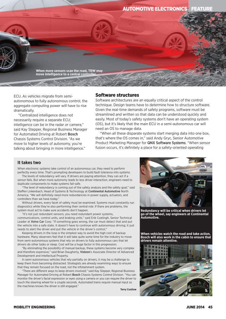
MOBILITY ENGINEERING JUNE 2014 45
AUTOMOTIVE ELECTRONICS FEATURE
It takes twoWhen electronic systems take control of an autonomous car, they need to perform perfectly every time. That’s prompting developers to build fault tolerance into systems.
The levels of redundancy will vary. If drivers are paying attention, they can act if a sensor fails. But when more autonomy leads to less driver interaction, engineers need to duplicate components to make systems fail-safe.
“The level of redundancy is coming out of the safety analysis and the safety goal,” said Steffen Linkenbach, Head of Systems & Technology at Continental Automotive North America. “We will definitely need more redundancies in power supply, actuators, and controllers than we have today.”
Without drivers, every facet of safety must be examined. Systems must constantly run diagnostics while they’re also performing their central role. If there are problems, the system must act to make sure accidents don’t happen.
“It’s not just redundant sensors; you need redundant power systems, communications, control units, and braking units,” said Erik Coelingh, Senior Technical Leader at Volvo Car Corp. “If something goes wrong, the car must detect that and put the vehicle into a safe state. It doesn’t have to continue with autonomous driving; it just needs to alert the driver and put the vehicle in the driver’s control.”
Keeping drivers in the loop is the simplest way to avoid the high cost of backup hardware. Many observers feel that it will take quite some time for the industry to move from semi-autonomous systems that rely on drivers to fully autonomous cars that let drivers do other tasks or sleep. Cost will be a huge factor in this progression.
“By eliminating the possibility of manual backup, these systems become very complex and therefore expensive,” said Brian Daugherty, Visteon’s Associate Director of Advanced Development and Intellectual Property.
In semi-autonomous vehicles that rely partially on drivers, it may be a challenge to keep them from becoming distracted. Strategists are already examining ways to ensure that they remain focused on the road, not the infotainment system.
“There are different ways to keep drivers involved,” said Kay Stepper, Regional Business Manager for Automated Driving at Robert Bosch Chassis Systems Control Division. “You can monitor the driver’s facial expression or eyes using a camera or you can require the driver to touch the steering wheel for a couple seconds. Automated trains require manual input so the machines knows the driver is still engaged.”
Terry Costlow
ECU. As vehicles migrate from semi-autonomous to fully autonomous control, the aggregate computing power will have to rise dramatically.
“Centralized intelligence does not necessarily require a separate ECU; intelligence can be in the radar or camera,” said Kay Stepper, Regional Business Manager for Automated Driving at Robert Bosch Chassis Systems Control Division. “As we move to higher levels of autonomy, you’re talking about bringing in more intelligence.”
Software structuresSoftware architectures are an equally critical aspect of the control technique. Design teams have to determine how to structure software. Given the real-time demands of safety programs, software must be streamlined and written so that data can be understood quickly and easily. Most of today’s safety systems don’t have an operating system (OS), but it’s likely that the main ECU in a semi-autonomous car will need an OS to manage data.
“When all these disparate systems start merging data into one box, that’s where the OS comes in,” said Andy Gryc, Senior Automotive Product Marketing Manager for QNX Software Systems. “When sensor fusion occurs, it’s definitely a place for a safety-oriented operating
Redundancy will be critical when drivers let go of the wheel, say engineers at Continental Automotive.
When vehicles watch the road and take action, Bosch will also work in the cabin to ensure that drivers remain attentive.
When more sensors scan the road, TRW may move intelligence to a central controller.
AUTOMOTIVE ELECTRONICS FEATURE
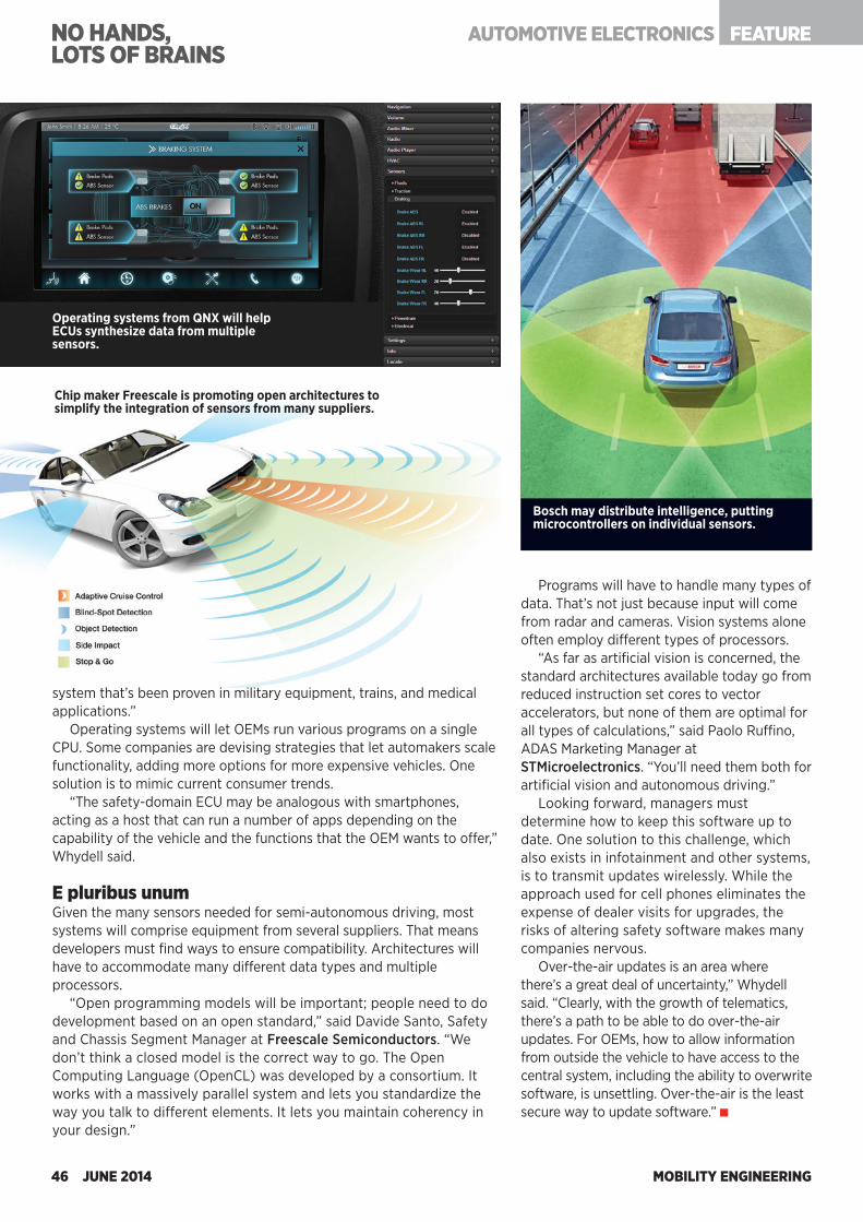
MOBILITY ENGINEERING46 JUNE 2014
NO HANDS, LOTS OF BRAINS
Operating systems from QNX will help ECUs synthesize data from multiple sensors.
Chip maker Freescale is promoting open architectures to simplify the integration of sensors from many suppliers.
Bosch may distribute intelligence, putting microcontrollers on individual sensors.
system that’s been proven in military equipment, trains, and medical applications.”
Operating systems will let OEMs run various programs on a single CPU. Some companies are devising strategies that let automakers scale functionality, adding more options for more expensive vehicles. One solution is to mimic current consumer trends.
“The safety-domain ECU may be analogous with smartphones, acting as a host that can run a number of apps depending on the capability of the vehicle and the functions that the OEM wants to offer,” Whydell said. E pluribus unumGiven the many sensors needed for semi-autonomous driving, most systems will comprise equipment from several suppliers. That means developers must find ways to ensure compatibility. Architectures will have to accommodate many different data types and multiple processors.
“Open programming models will be important; people need to do development based on an open standard,” said Davide Santo, Safety and Chassis Segment Manager at Freescale Semiconductors. “We don’t think a closed model is the correct way to go. The Open Computing Language (OpenCL) was developed by a consortium. It works with a massively parallel system and lets you standardize the way you talk to different elements. It lets you maintain coherency in your design.”
Programs will have to handle many types of data. That’s not just because input will come from radar and cameras. Vision systems alone often employ different types of processors.
“As far as artificial vision is concerned, the standard architectures available today go from reduced instruction set cores to vector accelerators, but none of them are optimal for all types of calculations,” said Paolo Ruffino, ADAS Marketing Manager at STMicroelectronics. “You’ll need them both for artificial vision and autonomous driving.”
Looking forward, managers must determine how to keep this software up to date. One solution to this challenge, which also exists in infotainment and other systems, is to transmit updates wirelessly. While the approach used for cell phones eliminates the expense of dealer visits for upgrades, the risks of altering safety software makes many companies nervous.
Over-the-air updates is an area where there’s a great deal of uncertainty,” Whydell said. “Clearly, with the growth of telematics, there’s a path to be able to do over-the-air updates. For OEMs, how to allow information from outside the vehicle to have access to the central system, including the ability to overwrite software, is unsettling. Over-the-air is the least secure way to update software.”
AUTOMOTIVE ELECTRONICS FEATURE
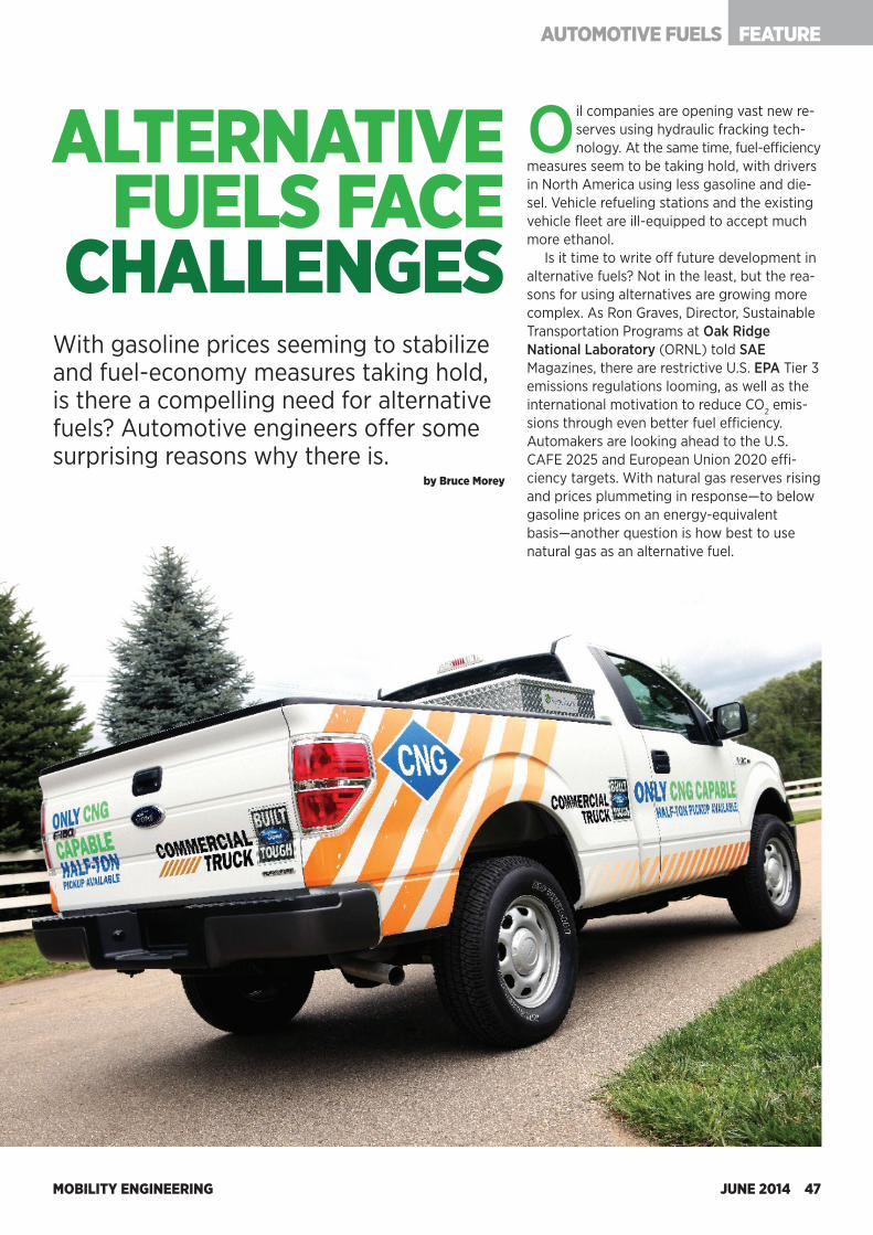
MOBILITY ENGINEERING46 JUNE 2014
NO HANDS, LOTS OF BRAINS
Operating systems from QNX will help ECUs synthesize data from multiple sensors.
Chip maker Freescale is promoting open architectures to simplify the integration of sensors from many suppliers.
Bosch may distribute intelligence, putting microcontrollers on individual sensors.
system that’s been proven in military equipment, trains, and medical applications.”
Operating systems will let OEMs run various programs on a single CPU. Some companies are devising strategies that let automakers scale functionality, adding more options for more expensive vehicles. One solution is to mimic current consumer trends.
“The safety-domain ECU may be analogous with smartphones, acting as a host that can run a number of apps depending on the capability of the vehicle and the functions that the OEM wants to offer,” Whydell said. E pluribus unumGiven the many sensors needed for semi-autonomous driving, most systems will comprise equipment from several suppliers. That means developers must find ways to ensure compatibility. Architectures will have to accommodate many different data types and multiple processors.
“Open programming models will be important; people need to do development based on an open standard,” said Davide Santo, Safety and Chassis Segment Manager at Freescale Semiconductors. “We don’t think a closed model is the correct way to go. The Open Computing Language (OpenCL) was developed by a consortium. It works with a massively parallel system and lets you standardize the way you talk to different elements. It lets you maintain coherency in your design.”
Programs will have to handle many types of data. That’s not just because input will come from radar and cameras. Vision systems alone often employ different types of processors.
“As far as artificial vision is concerned, the standard architectures available today go from reduced instruction set cores to vector accelerators, but none of them are optimal for all types of calculations,” said Paolo Ruffino, ADAS Marketing Manager at STMicroelectronics. “You’ll need them both for artificial vision and autonomous driving.”
Looking forward, managers must determine how to keep this software up to date. One solution to this challenge, which also exists in infotainment and other systems, is to transmit updates wirelessly. While the approach used for cell phones eliminates the expense of dealer visits for upgrades, the risks of altering safety software makes many companies nervous.
Over-the-air updates is an area where there’s a great deal of uncertainty,” Whydell said. “Clearly, with the growth of telematics, there’s a path to be able to do over-the-air updates. For OEMs, how to allow information from outside the vehicle to have access to the central system, including the ability to overwrite software, is unsettling. Over-the-air is the least secure way to update software.”
AUTOMOTIVE ELECTRONICS FEATURE
MOBILITY ENGINEERING JUNE 2014 47
FEATUREAUTOMOTIVE FUELS
With gasoline prices seeming to stabilize and fuel-economy measures taking hold, is there a compelling need for alternative fuels? Automotive engineers offer some surprising reasons why there is.
by Bruce Morey
ALTERNATIVE FUELS FACE
CHALLENGES
Oil companies are opening vast new re-serves using hydraulic fracking tech-nology. At the same time, fuel-efficiency
measures seem to be taking hold, with drivers in North America using less gasoline and die-sel. Vehicle refueling stations and the existing vehicle fleet are ill-equipped to accept much more ethanol.
Is it time to write off future development in alternative fuels? Not in the least, but the rea-sons for using alternatives are growing more complex. As Ron Graves, Director, Sustainable Transportation Programs at Oak Ridge National Laboratory (ORNL) told SAE Magazines, there are restrictive U.S. EPA Tier 3 emissions regulations looming, as well as the international motivation to reduce CO2 emis-sions through even better fuel efficiency. Automakers are looking ahead to the U.S. CAFE 2025 and European Union 2020 effi-ciency targets. With natural gas reserves rising and prices plummeting in response—to below gasoline prices on an energy-equivalent basis—another question is how best to use natural gas as an alternative fuel.
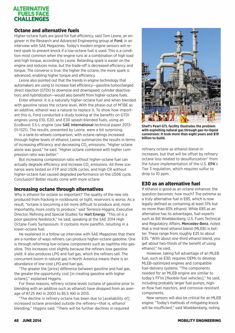
MOBILITY ENGINEERING48 JUNE 2014
ALTERNATIVE FUELS FACE
CHALLENGES
refinery octane as ethanol blend-in increases, but that will be offset by refinery octane loss related to desulfurization” from the future implementation of the U.S. EPA’s Tier 3 regulation, which requires sulfur to drop to 10 ppm.
E30 as an alternative fuel If ethanol is good as an octane enhancer, the question becomes: how much? The extreme as a truly alternative fuel is E85, which is now legally defined as containing at least 51% but no more than 83% ethanol. While E85 as an alternative has its advantages, fuel experts such as Bill Woebkenberg, U.S. Fuels Technical and Regulatory Affairs, Mercedes-Benz, noted that a mid-level ethanol blend (MLEB) is bet-ter. These range from roughly E25 to about E35. “With about one-third ethanol blend, you get about two-thirds of the benefit of using ethanol,” he said.
However, taking full advantage of an MLEB fuel, such as E30, requires OEMs to develop MLEB-optimized engines and compatible fuel-delivery systems. “The components needed for an MLEB engine are similar to today’s FFVs [flexible-fuel vehicles],” he said, including probably larger fuel pumps, high-er-flow fuel injectors, and corrosive-resistant components.
New sensors will also be critical for an MLEB engine. “Today’s methods of mitigating knock will be insufficient,” said Woebkenberg, noting
Shell’s Pearl GTL facility illustrates the problem with exploiting natural gas through gas-to-liquid conversion: It took more than eight years and $19 billion to build.
Octane and alternative fuels Higher-octane fuels are good for fuel efficiency, said Tom Leone, an en-gineer in the Research and Advanced Engineering group at Ford, in an interview with SAE Magazines. Today’s modern engine sensors will re-tard spark to prevent knock if a low-octane fuel is used. This is a condi-tion most common when the engine runs at a combination of high load and high torque, according to Leone. Retarding spark is easier on the engine and reduces noise, but the trade-off is decreased efficiency and torque. The converse is true: the higher the octane, the more spark is advanced, enabling higher torque and efficiency.
Leone also pointed out that the trends in engine technology that automakers are using to increase fuel efficiency—gasoline turbocharged direct injection (GTDI) to downsize and downspeed; cylinder deactiva-tion; and hybridization—would also benefit from higher-octane fuels.
Enter ethanol. It is a naturally higher-octane fuel and when blended with gasoline raises the octane level. With the phase-out of MTBE as an additive, ethanol was a natural to replace it. To show how import-ant this is, Ford conducted a study looking at the benefits on GTDI engines using E10, E20, and E30 splash-blended fuels, using an EcoBoost 3.5-L engine (see SAE International technical paper 2013-01-1321). The results, presented by Leone, were a bit surprising.
In a tank-to-wheels comparison, with octane ratings increased through higher levels of ethanol, Leone summarizes the results in terms of increasing efficiency and decreasing CO2 emissions. “Higher octane alone was good,” he said. “Higher octane combined with higher com-pression ratio was better.”
But increasing compression ratio without higher-octane fuel can actually degrade efficiency and increase CO2 emissions. All three sce-narios were tested on FTP and US06 cycles, and high CR without higher-octane fuel caused degraded performance on the US06 cycle. Conclusion? Better results come with more octane. Increasing octane through alternatives Why is ethanol for octane so important? The quality of the new oils produced from fracking in rockbound, or tight, reservoirs is worse. As a result, “octane is becoming a bit more difficult to produce and, more importantly, more costly to produce,” said Terrence Higgins, Executive Director, Refining and Special Studies for Hart Energy. “This oil is a poor gasoline feedstock,” he said, speaking at the SAE 2014 High Octane Fuels Symposium. It contains more paraffin, resulting in a lower-octane fuel.
He explained in a follow-up interview with SAE Magazines that there are a number of ways refiners can produce higher-octane gasoline. One is through reforming low-octane components such as naphtha into gas-oline. This increases cost slightly because the refiners lose gasoline yield. It also produces LPG and fuel gas, which the refiners sell. The concurrent boom in natural gas in North America means there is an abundance of low-cost LPG and fuel gas.
“The greater the [price] difference between gasoline and fuel gas, the greater the opportunity cost [in creating gasoline with higher octane],” explained Higgins.
For these reasons, refinery octane levels (octane of gasoline prior to blending with an additive such as ethanol) have dropped from an aver-age of 87.25 AKI in 2003 to 85.5 AKI in 2013.
“The decline in refinery octane has been due to [availability of] increased octane provided outside the refinery—that is, ethanol blending,” Higgins said. “There will be further declines in required
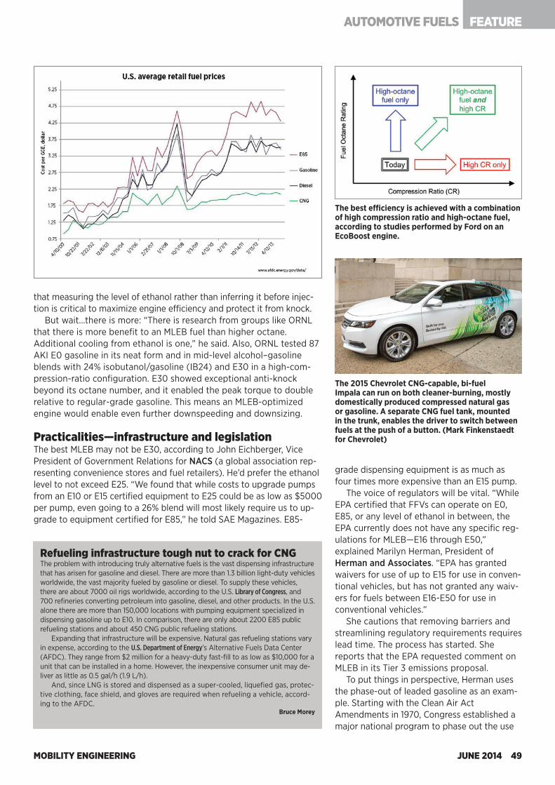
MOBILITY ENGINEERING JUNE 2014 49
FEATUREAUTOMOTIVE FUELS
that measuring the level of ethanol rather than inferring it before injec-tion is critical to maximize engine efficiency and protect it from knock.
But wait…there is more: “There is research from groups like ORNL that there is more benefit to an MLEB fuel than higher octane. Additional cooling from ethanol is one,” he said. Also, ORNL tested 87 AKI E0 gasoline in its neat form and in mid-level alcohol–gasoline blends with 24% isobutanol/gasoline (IB24) and E30 in a high-com-pression-ratio configuration. E30 showed exceptional anti-knock beyond its octane number, and it enabled the peak torque to double relative to regular-grade gasoline. This means an MLEB-optimized engine would enable even further downspeeding and downsizing. Practicalities—infrastructure and legislation The best MLEB may not be E30, according to John Eichberger, Vice President of Government Relations for NACS (a global association rep-resenting convenience stores and fuel retailers). He’d prefer the ethanol level to not exceed E25. “We found that while costs to upgrade pumps from an E10 or E15 certified equipment to E25 could be as low as $5000 per pump, even going to a 26% blend will most likely require us to up-grade to equipment certified for E85,” he told SAE Magazines. E85-
The best efficiency is achieved with a combination of high compression ratio and high-octane fuel, according to studies performed by Ford on an EcoBoost engine.
grade dispensing equipment is as much as four times more expensive than an E15 pump.
The voice of regulators will be vital. “While EPA certified that FFVs can operate on E0, E85, or any level of ethanol in between, the EPA currently does not have any specific reg-ulations for MLEB—E16 through E50,” explained Marilyn Herman, President of Herman and Associates. “EPA has granted waivers for use of up to E15 for use in conven-tional vehicles, but has not granted any waiv-ers for fuels between E16-E50 for use in conventional vehicles.”
She cautions that removing barriers and streamlining regulatory requirements requires lead time. The process has started. She reports that the EPA requested comment on MLEB in its Tier 3 emissions proposal.
To put things in perspective, Herman uses the phase-out of leaded gasoline as an exam-ple. Starting with the Clean Air Act Amendments in 1970, Congress established a major national program to phase out the use
The 2015 Chevrolet CNG-capable, bi-fuel Impala can run on both cleaner-burning, mostly domestically produced compressed natural gas or gasoline. A separate CNG fuel tank, mounted in the trunk, enables the driver to switch between fuels at the push of a button. (Mark Finkenstaedt for Chevrolet)
Refueling infrastructure tough nut to crack for CNGThe problem with introducing truly alternative fuels is the vast dispensing infrastructure that has arisen for gasoline and diesel. There are more than 1.3 billion light-duty vehicles worldwide, the vast majority fueled by gasoline or diesel. To supply these vehicles, there are about 7000 oil rigs worldwide, according to the U.S. Library of Congress, and 700 refineries converting petroleum into gasoline, diesel, and other products. In the U.S. alone there are more than 150,000 locations with pumping equipment specialized in dispensing gasoline up to E10. In comparison, there are only about 2200 E85 public refueling stations and about 450 CNG public refueling stations.
Expanding that infrastructure will be expensive. Natural gas refueling stations vary in expense, according to the U.S. Department of Energy’s Alternative Fuels Data Center (AFDC). They range from $2 million for a heavy-duty fast-fill to as low as $10,000 for a unit that can be installed in a home. However, the inexpensive consumer unit may de-liver as little as 0.5 gal/h (1.9 L/h).
And, since LNG is stored and dispensed as a super-cooled, liquefied gas, protec-tive clothing, face shield, and gloves are required when refueling a vehicle, accord-ing to the AFDC.
Bruce Morey
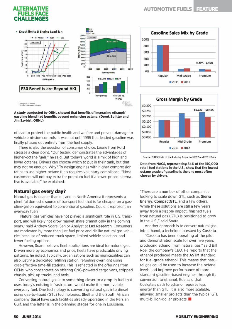
MOBILITY ENGINEERING50 JUNE 2014
of lead to protect the public health and welfare and prevent damage to vehicle emission controls; it was not until 1995 that leaded gasoline was finally phased out entirely from the fuel supply.
There is also the question of consumer choice. Leone from Ford stresses a clear point. “Our testing demonstrates the advantages of higher-octane fuels,” he said. But today’s world is a mix of high and lower octanes. Drivers can choose which to put in their tank, but that may not be enough. Why? To design engines with higher compression ratios to use higher-octane fuels requires voluntary compliance. “Most customers will not pay extra for premium fuel if a lower-priced alterna-tive is available,” he explained. Natural gas every day? Natural gas is cleaner than oil, and in North America it represents a plentiful domestic source of transport fuel that is far cheaper on a gas-oline-gallon equivalent to conventional gasoline. Could it represent an everyday fuel?
“Natural gas vehicles have not played a significant role in U.S. trans-port, and will likely not grow market share dramatically in the coming years,” said Andrew Soare, Senior Analyst at Lux Research. Consumers are motivated by more than just fuel price and dislike natural gas vehi-cles because of reduced trunk space, limited vehicle selection, and fewer fueling options.
However, Soare believes fleet applications are ideal for natural gas. Driven more by economics and price, fleets have predictable driving patterns, he noted. Typically, organizations such as municipalities can also justify a dedicated refilling station, refueling overnight using cost-effective time-fill stations. This is reflected in the offerings from OEMs, who concentrate on offering CNG-powered cargo vans, stripped chassis, pick-up trucks, and taxis.
Converting natural gas into something closer to a drop-in fuel that uses today’s existing infrastructure would make it a more viable everyday fuel. One technology is converting natural gas into diesel using gas-to-liquid (GTL) technologies. Shell and the South African company Sasol have such facilities already operating in the Persian Gulf, and the latter is in the planning stages for one in Louisiana.
“There are a number of other companies looking to scale down GTL, such as Sierra Energy, CompactGTL, and a few others. While these solutions are still a few years away from a sizable impact, finished fuels from natural gas (GTL) is positioned to grow in the U.S.,” said Soare.
Another approach is to convert natural gas into ethanol, a technique pursued by Coskata.
“Coskata has been operating at the pilot and demonstration scale for over five years producing ethanol from natural gas,” said Bill Roe, the company’s CEO. He reports that the ethanol produced meets the ASTM standard for fuel-grade ethanol. This means that natu-ral gas could be used to increase the octane levels and improve performance of more standard gasoline-based engines through its conversion to ethanol. Roe said that Coskata’s path to ethanol requires less energy than GTL. It is also more scalable, allowing smaller projects than the typical GTL multi-billion-dollar projects.
A study conducted by ORNL showed that benefits of increasing ethanol/gasoline blend had benefits beyond enhancing octane. (Derek Splitter and Jim Szybist, ORNL)
Data from NACS, representing 84% of the 150,000 retail fuel stations in the U.S., show that the lowest octane grade of gasoline is the one most often chosen by drivers.
FEATUREAUTOMOTIVE FUELSALTERNATIVE FUELS FACE
CHALLENGES
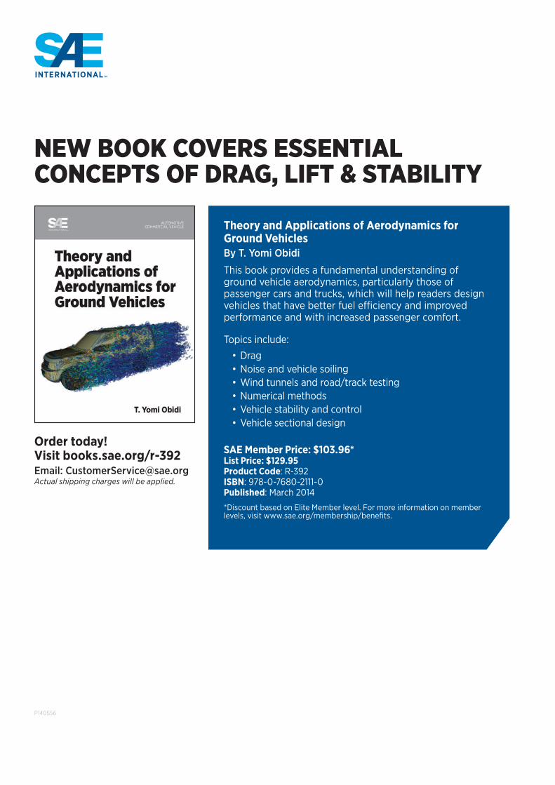
P140556
NEW BOOK COVERS ESSENTIAL CONCEPTS OF DRAG, LIFT & STABILITY
Order today! Visit books.sae.org/r-392Email: [email protected] shipping charges will be applied.
Theory and Applications of Aerodynamics for Ground VehiclesBy T. Yomi Obidi
This book provides a fundamental understanding of ground vehicle aerodynamics, particularly those of passenger cars and trucks, which will help readers design vehicles that have better fuel efficiency and improved performance and with increased passenger comfort.
Topics include:
• Drag• Noise and vehicle soiling• Wind tunnels and road/track testing• Numerical methods• Vehicle stability and control• Vehicle sectional design
SAE Member Price: $103.96*List Price: $129.95Product Code: R-392ISBN: 978-0-7680-2111-0Published: March 2014
*Discount based on Elite Member level. For more information on member levels, visit www.sae.org/membership/benefits.
MOBILITY ENGINEERING52 JUNE 2014
FEATURE AEROSPACE PROPULSION
Global warming and environmental friendliness considerations have re-cently been key for multiple global industries. In the commercial avia-
tion industry, reduction of aircraft emissions, including CO2 and noise, is an urgent priority. Both aircraft and aircraft engine manufacturers are striving to improve designs to accommodate the needs of commercial airlines. Engine manufac-turers in particular have worked long and hard to improve each engine component, e.g., compressors, turbines, combustors, etc.
However, the need for another approach to further improve engine efficiency motivated researchers from IHI Aerospace to focus on the system approach, including the control system, fuel system, or other engine systems, ultimately resulting in MEE (more electric engine).
MEE is a new engine system concept that seeks engine efficiency improvements, which results in a reduction of engine fuel burn and CO2 emissions. The key concept of the MEE system involves the architecture for the electrical power generation by the engine and changing the power source for accessories from mechanical/hydraulic to an electric motor.
IHI focused on the electrification of the engine fuel pump system because of its contribution to fuel-burn reduction. The researchers con-ducted a feasibility study of the MEE fuel system for an assumed small-size turbofan engine, and the result indicated an improvement in specific fuel consumption (SFC) by about 1% during cruising. The SFC
More electric, integrated fuel systems
Engine system reliability can be improved by advanced electric architectures, while the reduction of hydraulic components, fuel tubes, and fittings can enhance the maintainability of the engine and minimize pilot workload.
improvement would be accomplished by removing the fuel bypass circuit and elimi-nating the ACOC (air-cooled oil cooler), which worsens engine efficiency.
There are several technical challenges for the practical design of the MEE motor-driven fuel pump system. Failure of the engine fuel pump may induce IFSD (in-flight shutdown) of the engine and result in catastrophic failure of the aircraft. To avoid such critical situations and ensure better reliability than that of the conventional system, a fault-tolerant design of the electric drive is mandatory.
For the MEE fuel pump system currently being developed, IHI has proposed the use of a permanent magnet brushless ac servo motor. In the servo motor control system, the electrical current is adequately controlled cor-
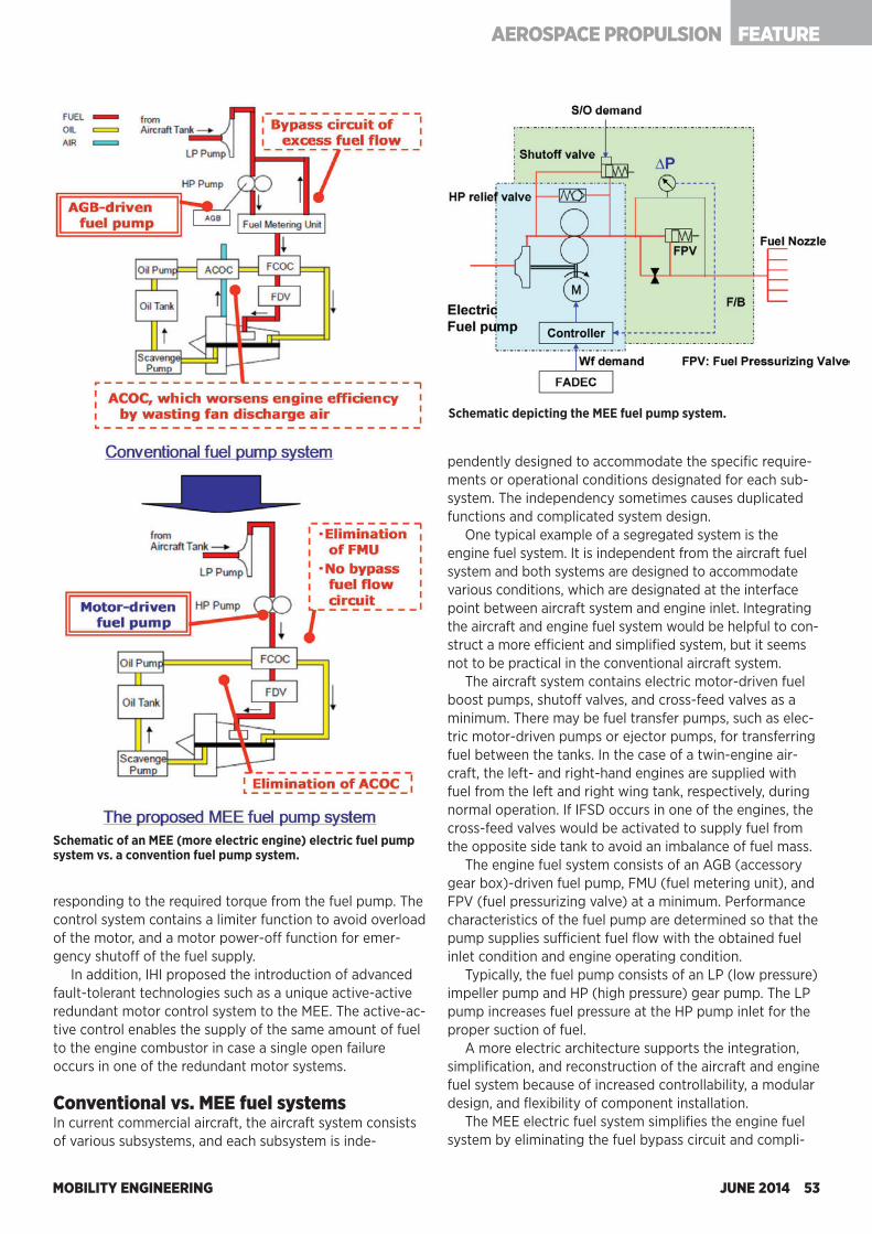
MOBILITY ENGINEERING JUNE 2014 53
FEATUREAEROSPACE PROPULSION
responding to the required torque from the fuel pump. The control system contains a limiter function to avoid overload of the motor, and a motor power-off function for emer-gency shutoff of the fuel supply.
In addition, IHI proposed the introduction of advanced fault-tolerant technologies such as a unique active-active redundant motor control system to the MEE. The active-ac-tive control enables the supply of the same amount of fuel to the engine combustor in case a single open failure occurs in one of the redundant motor systems. Conventional vs. MEE fuel systems In current commercial aircraft, the aircraft system consists of various subsystems, and each subsystem is inde-
Schematic of an MEE (more electric engine) electric fuel pump system vs. a convention fuel pump system.
pendently designed to accommodate the specific require-ments or operational conditions designated for each sub-system. The independency sometimes causes duplicated functions and complicated system design.
One typical example of a segregated system is the engine fuel system. It is independent from the aircraft fuel system and both systems are designed to accommodate various conditions, which are designated at the interface point between aircraft system and engine inlet. Integrating the aircraft and engine fuel system would be helpful to con-struct a more efficient and simplified system, but it seems not to be practical in the conventional aircraft system.
The aircraft system contains electric motor-driven fuel boost pumps, shutoff valves, and cross-feed valves as a minimum. There may be fuel transfer pumps, such as elec-tric motor-driven pumps or ejector pumps, for transferring fuel between the tanks. In the case of a twin-engine air-craft, the left- and right-hand engines are supplied with fuel from the left and right wing tank, respectively, during normal operation. If IFSD occurs in one of the engines, the cross-feed valves would be activated to supply fuel from the opposite side tank to avoid an imbalance of fuel mass.
The engine fuel system consists of an AGB (accessory gear box)-driven fuel pump, FMU (fuel metering unit), and FPV (fuel pressurizing valve) at a minimum. Performance characteristics of the fuel pump are determined so that the pump supplies sufficient fuel flow with the obtained fuel inlet condition and engine operating condition.
Typically, the fuel pump consists of an LP (low pressure) impeller pump and HP (high pressure) gear pump. The LP pump increases fuel pressure at the HP pump inlet for the proper suction of fuel.
A more electric architecture supports the integration, simplification, and reconstruction of the aircraft and engine fuel system because of increased controllability, a modular design, and flexibility of component installation.
The MEE electric fuel system simplifies the engine fuel system by eliminating the fuel bypass circuit and compli-
Schematic depicting the MEE fuel pump system.
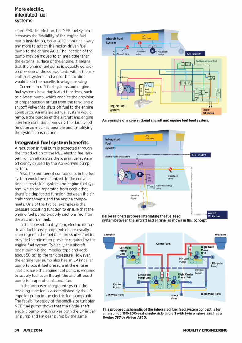
MOBILITY ENGINEERING54 JUNE 2014
FEATURE
cated FMU. In addition, the MEE fuel system increases the flexibility of the engine fuel pump installation, because it is not necessary any more to attach the motor-driven fuel pump to the engine AGB. The location of the pump may be moved to an area other than the external surface of the engine. It means that the engine fuel pump is possibly consid-ered as one of the components within the air-craft fuel system, and a possible location would be in the nacelle, fuselage, or wing.
Current aircraft fuel systems and engine fuel systems have duplicated functions, such as a boost pump, which enables the provision of proper suction of fuel from the tank, and a shutoff valve that shuts off fuel to the engine combustor. An integrated fuel system would remove the burden of the aircraft and engine interface condition, removing the duplicated function as much as possible and simplifying the system construction.
Integrated fuel system benefits A reduction in fuel burn is expected through the introduction of the MEE electric fuel sys-tem, which eliminates the loss in fuel system efficiency caused by the AGB-driven pump system.
Also, the number of components in the fuel system would be minimized. In the conven-tional aircraft fuel system and engine fuel sys-tem, which are separated from each other, there is a duplicated function between the air-craft components and the engine compo-nents. One of the typical examples is the pressure boosting function to ensure that the engine fuel pump properly suctions fuel from the aircraft fuel tank.
In the conventional system, electric motor-driven fuel boost pumps, which are usually submerged in the fuel tank, pressurize fuel to provide the minimum pressure required by the engine fuel system. Typically, the aircraft boost pump is the impeller type and adds about 50 psi to the tank pressure. However, the engine fuel pump also has an LP impeller pump to boost fuel pressure at the engine inlet because the engine fuel pump is required to supply fuel even though the aircraft boost pump is in operational condition.
In the proposed integrated system, the boosting function is accomplished by the LP impeller pump in the electric fuel pump unit. The feasibility study of the small-size turbofan MEE fuel pump shows that the single-shaft electric pump, which drives both the LP impel-ler pump and HP gear pump by the same
An example of a conventional aircraft and engine fuel feed system.
IHI researchers propose integrating the fuel feed system between the aircraft and engine, as shown in this concept.
This proposed schematic of the integrated fuel feed system concept is for an assumed 150-200-seat single-aisle aircraft with twin engines, such as a Boeing 737 or Airbus A320.
More electric, integrated fuel systems
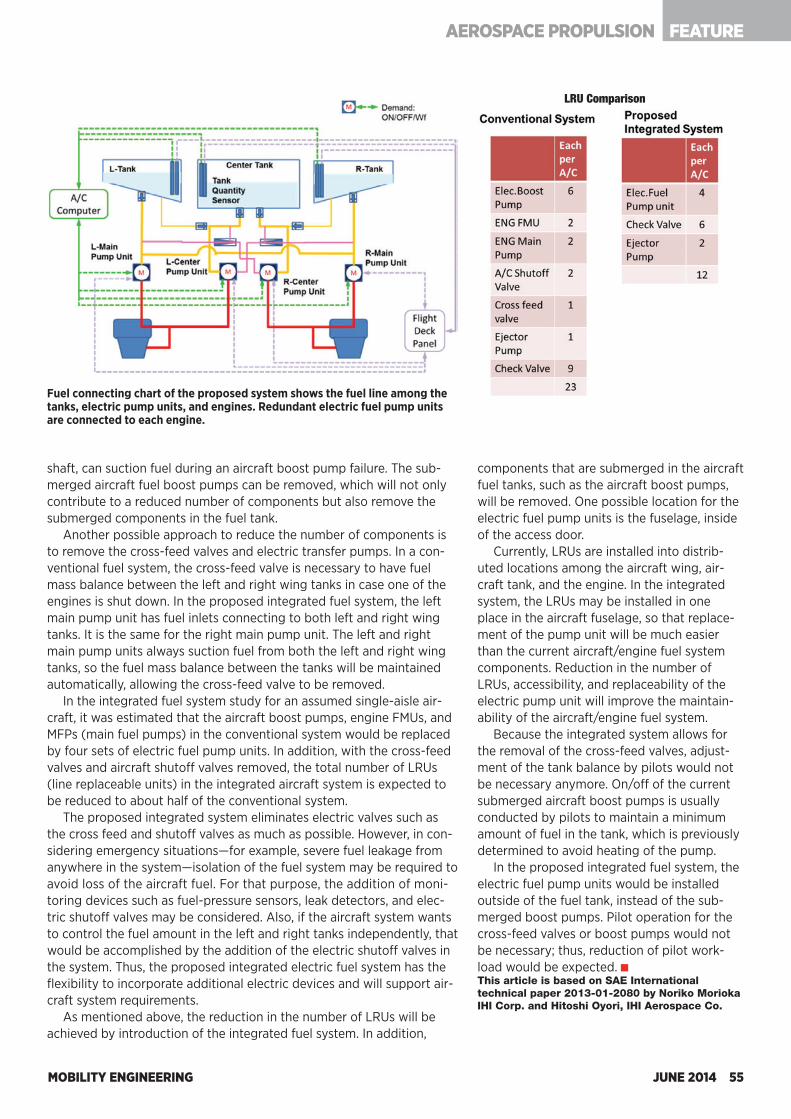
MOBILITY ENGINEERING JUNE 2014 55
FEATUREAEROSPACE PROPULSION
shaft, can suction fuel during an aircraft boost pump failure. The sub-merged aircraft fuel boost pumps can be removed, which will not only contribute to a reduced number of components but also remove the submerged components in the fuel tank.
Another possible approach to reduce the number of components is to remove the cross-feed valves and electric transfer pumps. In a con-ventional fuel system, the cross-feed valve is necessary to have fuel mass balance between the left and right wing tanks in case one of the engines is shut down. In the proposed integrated fuel system, the left main pump unit has fuel inlets connecting to both left and right wing tanks. It is the same for the right main pump unit. The left and right main pump units always suction fuel from both the left and right wing tanks, so the fuel mass balance between the tanks will be maintained automatically, allowing the cross-feed valve to be removed.
In the integrated fuel system study for an assumed single-aisle air-craft, it was estimated that the aircraft boost pumps, engine FMUs, and MFPs (main fuel pumps) in the conventional system would be replaced by four sets of electric fuel pump units. In addition, with the cross-feed valves and aircraft shutoff valves removed, the total number of LRUs (line replaceable units) in the integrated aircraft system is expected to be reduced to about half of the conventional system.
The proposed integrated system eliminates electric valves such as the cross feed and shutoff valves as much as possible. However, in con-sidering emergency situations—for example, severe fuel leakage from anywhere in the system—isolation of the fuel system may be required to avoid loss of the aircraft fuel. For that purpose, the addition of moni-toring devices such as fuel-pressure sensors, leak detectors, and elec-tric shutoff valves may be considered. Also, if the aircraft system wants to control the fuel amount in the left and right tanks independently, that would be accomplished by the addition of the electric shutoff valves in the system. Thus, the proposed integrated electric fuel system has the flexibility to incorporate additional electric devices and will support air-craft system requirements.
As mentioned above, the reduction in the number of LRUs will be achieved by introduction of the integrated fuel system. In addition,
components that are submerged in the aircraft fuel tanks, such as the aircraft boost pumps, will be removed. One possible location for the electric fuel pump units is the fuselage, inside of the access door.
Currently, LRUs are installed into distrib-uted locations among the aircraft wing, air-craft tank, and the engine. In the integrated system, the LRUs may be installed in one place in the aircraft fuselage, so that replace-ment of the pump unit will be much easier than the current aircraft/engine fuel system components. Reduction in the number of LRUs, accessibility, and replaceability of the electric pump unit will improve the maintain-ability of the aircraft/engine fuel system.
Because the integrated system allows for the removal of the cross-feed valves, adjust-ment of the tank balance by pilots would not be necessary anymore. On/off of the current submerged aircraft boost pumps is usually conducted by pilots to maintain a minimum amount of fuel in the tank, which is previously determined to avoid heating of the pump.
In the proposed integrated fuel system, the electric fuel pump units would be installed outside of the fuel tank, instead of the sub-merged boost pumps. Pilot operation for the cross-feed valves or boost pumps would not be necessary; thus, reduction of pilot work-load would be expected. This article is based on SAE International technical paper 2013-01-2080 by Noriko Morioka IHI Corp. and Hitoshi Oyori, IHI Aerospace Co.
Fuel connecting chart of the proposed system shows the fuel line among the tanks, electric pump units, and engines. Redundant electric fuel pump units are connected to each engine.
LRU Comparison
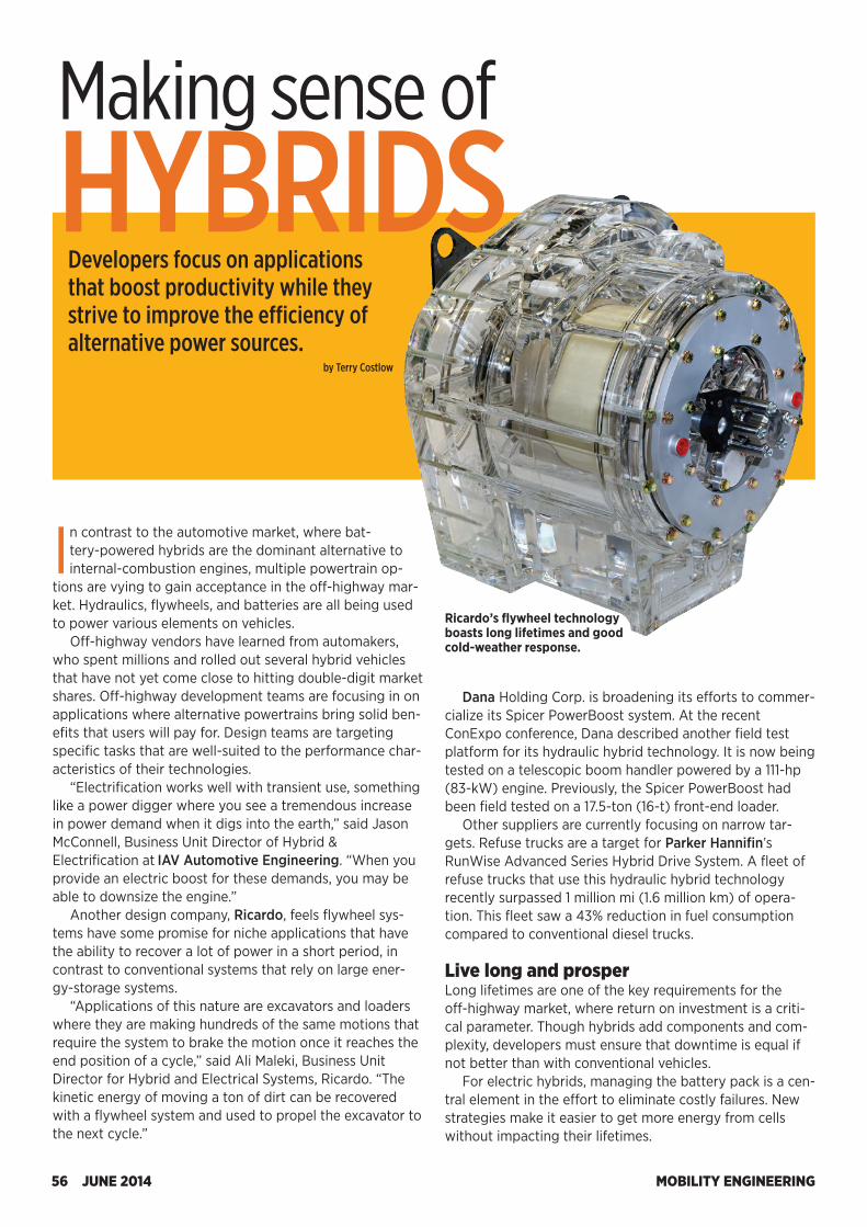
MOBILITY ENGINEERING56 JUNE 2014
Ricardo’s flywheel technology boasts long lifetimes and good cold-weather response.
Making sense of HYBRIDS
Developers focus on applications that boost productivity while they strive to improve the efficiency of alternative power sources.
by Terry Costlow
In contrast to the automotive market, where bat-tery-powered hybrids are the dominant alternative to internal-combustion engines, multiple powertrain op-
tions are vying to gain acceptance in the off-highway mar-ket. Hydraulics, flywheels, and batteries are all being used to power various elements on vehicles.
Off-highway vendors have learned from automakers, who spent millions and rolled out several hybrid vehicles that have not yet come close to hitting double-digit market shares. Off-highway development teams are focusing in on applications where alternative powertrains bring solid ben-efits that users will pay for. Design teams are targeting specific tasks that are well-suited to the performance char-acteristics of their technologies.
“Electrification works well with transient use, something like a power digger where you see a tremendous increase in power demand when it digs into the earth,” said Jason McConnell, Business Unit Director of Hybrid & Electrification at IAV Automotive Engineering. “When you provide an electric boost for these demands, you may be able to downsize the engine.”
Another design company, Ricardo, feels flywheel sys-tems have some promise for niche applications that have the ability to recover a lot of power in a short period, in contrast to conventional systems that rely on large ener-gy-storage systems.
“Applications of this nature are excavators and loaders where they are making hundreds of the same motions that require the system to brake the motion once it reaches the end position of a cycle,” said Ali Maleki, Business Unit Director for Hybrid and Electrical Systems, Ricardo. “The kinetic energy of moving a ton of dirt can be recovered with a flywheel system and used to propel the excavator to the next cycle.”
Dana Holding Corp. is broadening its efforts to commer-cialize its Spicer PowerBoost system. At the recent ConExpo conference, Dana described another field test platform for its hydraulic hybrid technology. It is now being tested on a telescopic boom handler powered by a 111-hp (83-kW) engine. Previously, the Spicer PowerBoost had been field tested on a 17.5-ton (16-t) front-end loader.
Other suppliers are currently focusing on narrow tar-gets. Refuse trucks are a target for Parker Hannifin’s RunWise Advanced Series Hybrid Drive System. A fleet of refuse trucks that use this hydraulic hybrid technology recently surpassed 1 million mi (1.6 million km) of opera-tion. This fleet saw a 43% reduction in fuel consumption compared to conventional diesel trucks. Live long and prosperLong lifetimes are one of the key requirements for the off-highway market, where return on investment is a criti-cal parameter. Though hybrids add components and com-plexity, developers must ensure that downtime is equal if not better than with conventional vehicles.
For electric hybrids, managing the battery pack is a cen-tral element in the effort to eliminate costly failures. New strategies make it easier to get more energy from cells without impacting their lifetimes.
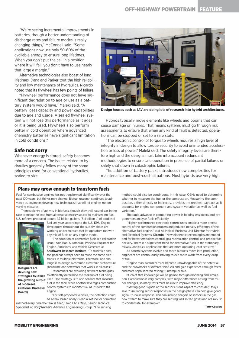
MOBILITY ENGINEERING JUNE 2014 57
FEATUREOFF-HIGHWAY POWERTRAIN
“We’re seeing incremental improvements in batteries, though a better understanding of discharge rates and failure modes is really changing things,” McConnell said. “Some applications now use only 50-60% of the available energy to ensure long lifetimes. When you don’t put the cell in a position where it will fail, you don’t have to use nearly that large a margin.”
Alternative technologies also boast of long lifetimes. Dana and Parker tout the high reliabil-ity and low maintenance of hydraulics. Ricardo noted that its flywheel has few points of failure.
“Flywheel performance does not have sig-nificant degradation to age or use as a bat-tery system would have,” Maleki said. “A battery loses capacity and power capabilities due to age and usage. A sealed flywheel sys-tem will not lose this performance as it ages or it is being used. Flywheels also perform better in cold operation where advanced chemistry batteries have significant limitation in cold conditions.” Safe not sorryWhenever energy is stored, safety becomes more of a concern. The issues related to hy-draulics generally follow many of the same principles used for conventional hydraulics, scaled to size.
Design houses such as IAV are doing lots of research into hybrid architectures.
Designers are devising new strategies to utilize the growing output of biodiesel. (National Biodiesel Board)
Fuel for combustion engines has not transformed significantly over the past 100 years, but things may change. Biofuel research continues to ad-vance as engineers develop new techniques that will let engines run on varying mixtures.
There’s plenty of activity in biofuels, though they trail natural gas in the race to make the leap from alternative energy source to mainstream fuel. U.S. refiners produced around 1.7 billion gallons (6.4 billion L) of biodiesel
fuel last year, according to the U.S. EPA. Engine developers throughout the supply chain are working on techniques that let operators run with any mix of fuels on any engine model.
“The adoption of alternative fuels is a calibration issue,” said Bapi Surampudi, Principal Engineer for Engine, Emissions, and Vehicle Research at Southwest Research Institute. “To minimize cost, the goal has always been to reuse the same elec-tronics in multiple platforms. Therefore, one chal-lenge is to design a common electronic architecture (hardware and software) that works in all cases.”
Researchers are exploring different techniques to efficiently determine the makeup of fuel being used. One strategy is to add sensors that measure fuel in the tank, while another leverages combustion control systems to monitor fuel as it’s fed to the engine.
“For self-propelled vehicles, the detection could be a tank-based analysis and a ‘retune’ or correction
method every time the tank is filled,” said Chris Mays, Senior Technical Specialist at BorgWarner’s Advance Engineering Group. “The sensing
method could also be continuous. In this case, OEMs need to determine whether to measure the fuel or the combustion. Measuring the com-bustion, either directly or indirectly, provides the greatest payback as it accounts for engine component and system variation as well as fuel variation.”
The rapid advance in computing power is helping engineers and pro-grammers analyze fuels efficiently.
“Higher-performance electronic control units enable a more precise control of the combustion process and reduced penalty efficiency of the alternative-fuel engine,” said Ali Maleki, Business Unit Director for Hybrid and Electrical Systems, Ricardo. “New electronic technologies are embed-ded for better emissions control, gas recirculation control, and precise fuel delivery. There is a significant trend for alternative fuels in the stationary, railway, and truck applications that are more operating-cost sensitive.”
As control systems evolve and more biofuels move into production, engineers are continuously striving to eke more work from every drop of fuel.
“Engine manufacturers must become knowledgeable of the potential and the drawbacks of different biofuels and gain experience through faster and more sophisticated testing,” Surampudi said.
Much of that knowledge will be gained through modeling and simula-tion. Combustion is very complex, with major differences arising from mi-nor changes, so many tests must be run to improve efficiency.
“Getting good signals at the sensors is one aspect to consider,” Mays said. “Simulating sensor responses in the design phase can help give good signal-to-noise response. This can include analysis of sensors in the gas flow stream to make sure they are sensing well-mixed gases and are robust to condensate, for example.”
Terry Costlow
Plans may grow enough to transform fuels
Hybrids typically move elements like wheels and booms that can cause damage or injuries. That means systems must go through risk assessments to ensure that when any kind of fault is detected, opera-tions can be stopped or set to a safe state.
“The electronic control of torque to wheels requires a high level of integrity in design to allow torque security to avoid unintended accelera-tion or loss of power,” Maleki said. The safety integrity levels are there-fore high and the designs must take into account redundant methodologies to ensure safe operation in presence of partial failures or safely shut down in catastrophic failures.
The addition of battery packs introduces new complexities for maintenance and post-crash situations. Most hybrids use very high
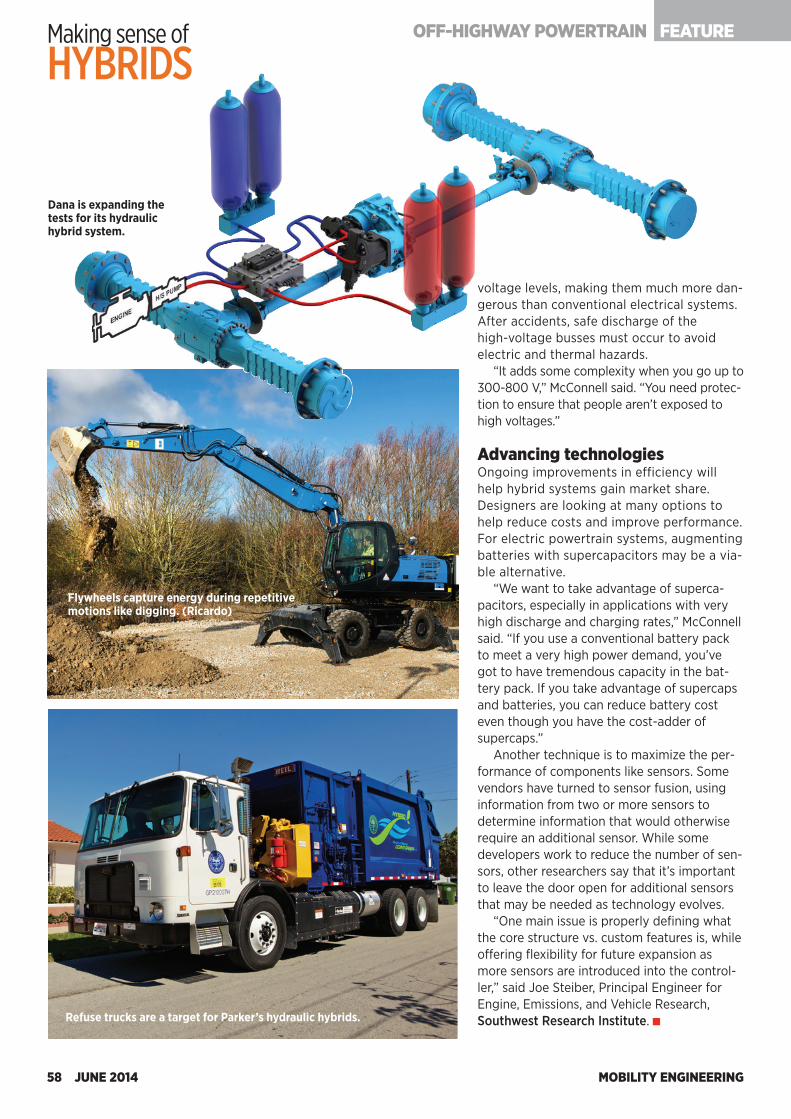
MOBILITY ENGINEERING58 JUNE 2014
voltage levels, making them much more dan-gerous than conventional electrical systems. After accidents, safe discharge of the high-voltage busses must occur to avoid electric and thermal hazards.
“It adds some complexity when you go up to 300-800 V,” McConnell said. “You need protec-tion to ensure that people aren’t exposed to high voltages.” Advancing technologiesOngoing improvements in efficiency will help hybrid systems gain market share. Designers are looking at many options to help reduce costs and improve performance. For electric powertrain systems, augmenting batteries with supercapacitors may be a via-ble alternative.
“We want to take advantage of superca-pacitors, especially in applications with very high discharge and charging rates,” McConnell said. “If you use a conventional battery pack to meet a very high power demand, you’ve got to have tremendous capacity in the bat-tery pack. If you take advantage of supercaps and batteries, you can reduce battery cost even though you have the cost-adder of supercaps.”
Another technique is to maximize the per-formance of components like sensors. Some vendors have turned to sensor fusion, using information from two or more sensors to determine information that would otherwise require an additional sensor. While some developers work to reduce the number of sen-sors, other researchers say that it’s important to leave the door open for additional sensors that may be needed as technology evolves.
“One main issue is properly defining what the core structure vs. custom features is, while offering flexibility for future expansion as more sensors are introduced into the control-ler,” said Joe Steiber, Principal Engineer for Engine, Emissions, and Vehicle Research, Southwest Research Institute.
Flywheels capture energy during repetitive motions like digging. (Ricardo)
Refuse trucks are a target for Parker’s hydraulic hybrids.
Dana is expanding the tests for its hydraulic hybrid system.
Making sense of HYBRIDS
FEATUREOFF-HIGHWAY POWERTRAIN
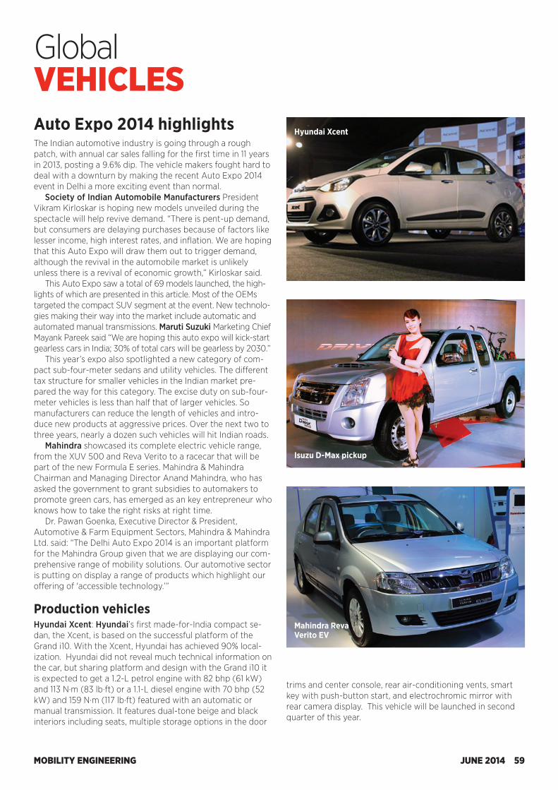
MOBILITY ENGINEERING JUNE 2014 59
GlobalVEHICLESAuto Expo 2014 highlightsThe Indian automotive industry is going through a rough patch, with annual car sales falling for the first time in 11 years in 2013, posting a 9.6% dip. The vehicle makers fought hard to deal with a downturn by making the recent Auto Expo 2014 event in Delhi a more exciting event than normal.
Society of Indian Automobile Manufacturers President Vikram Kirloskar is hoping new models unveiled during the spectacle will help revive demand. “There is pent-up demand, but consumers are delaying purchases because of factors like lesser income, high interest rates, and inflation. We are hoping that this Auto Expo will draw them out to trigger demand, although the revival in the automobile market is unlikely unless there is a revival of economic growth,” Kirloskar said.
This Auto Expo saw a total of 69 models launched, the high-lights of which are presented in this article. Most of the OEMs targeted the compact SUV segment at the event. New technolo-gies making their way into the market include automatic and automated manual transmissions. Maruti Suzuki Marketing Chief Mayank Pareek said “We are hoping this auto expo will kick-start gearless cars in India; 30% of total cars will be gearless by 2030.”
This year’s expo also spotlighted a new category of com-pact sub-four-meter sedans and utility vehicles. The different tax structure for smaller vehicles in the Indian market pre-pared the way for this category. The excise duty on sub-four-meter vehicles is less than half that of larger vehicles. So manufacturers can reduce the length of vehicles and intro-duce new products at aggressive prices. Over the next two to three years, nearly a dozen such vehicles will hit Indian roads.
Mahindra showcased its complete electric vehicle range, from the XUV 500 and Reva Verito to a racecar that will be part of the new Formula E series. Mahindra & Mahindra Chairman and Managing Director Anand Mahindra, who has asked the government to grant subsidies to automakers to promote green cars, has emerged as an key entrepreneur who knows how to take the right risks at right time.
Dr. Pawan Goenka, Executive Director & President, Automotive & Farm Equipment Sectors, Mahindra & Mahindra Ltd. said: “The Delhi Auto Expo 2014 is an important platform for the Mahindra Group given that we are displaying our com-prehensive range of mobility solutions. Our automotive sector is putting on display a range of products which highlight our offering of ‘accessible technology.’” Production vehiclesHyundai Xcent: Hyundai’s first made-for-India compact se-dan, the Xcent, is based on the successful platform of the Grand i10. With the Xcent, Hyundai has achieved 90% local-ization. Hyundai did not reveal much technical information on the car, but sharing platform and design with the Grand i10 it is expected to get a 1.2-L petrol engine with 82 bhp (61 kW) and 113 N·m (83 lb·ft) or a 1.1-L diesel engine with 70 bhp (52 kW) and 159 N·m (117 lb·ft) featured with an automatic or manual transmission. It features dual-tone beige and black interiors including seats, multiple storage options in the door
Hyundai Xcent
Isuzu D-Max pickup
Mahindra Reva Verito EV
trims and center console, rear air-conditioning vents, smart key with push-button start, and electrochromic mirror with rear camera display. This vehicle will be launched in second quarter of this year.
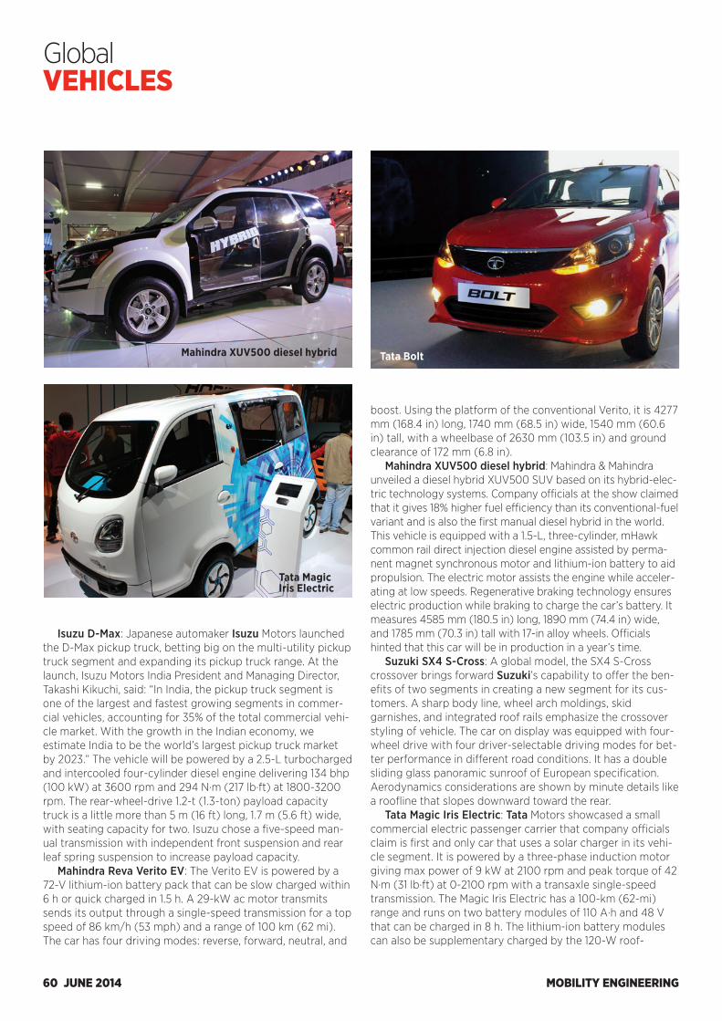
MOBILITY ENGINEERING60 JUNE 2014
Global VEHICLES
Isuzu D-Max: Japanese automaker Isuzu Motors launched the D-Max pickup truck, betting big on the multi-utility pickup truck segment and expanding its pickup truck range. At the launch, Isuzu Motors India President and Managing Director, Takashi Kikuchi, said: “In India, the pickup truck segment is one of the largest and fastest growing segments in commer-cial vehicles, accounting for 35% of the total commercial vehi-cle market. With the growth in the Indian economy, we estimate India to be the world’s largest pickup truck market by 2023.” The vehicle will be powered by a 2.5-L turbocharged and intercooled four-cylinder diesel engine delivering 134 bhp (100 kW) at 3600 rpm and 294 N·m (217 lb·ft) at 1800-3200 rpm. The rear-wheel-drive 1.2-t (1.3-ton) payload capacity truck is a little more than 5 m (16 ft) long, 1.7 m (5.6 ft) wide, with seating capacity for two. Isuzu chose a five-speed man-ual transmission with independent front suspension and rear leaf spring suspension to increase payload capacity.
Mahindra Reva Verito EV: The Verito EV is powered by a 72-V lithium-ion battery pack that can be slow charged within 6 h or quick charged in 1.5 h. A 29-kW ac motor transmits sends its output through a single-speed transmission for a top speed of 86 km/h (53 mph) and a range of 100 km (62 mi). The car has four driving modes: reverse, forward, neutral, and
boost. Using the platform of the conventional Verito, it is 4277 mm (168.4 in) long, 1740 mm (68.5 in) wide, 1540 mm (60.6 in) tall, with a wheelbase of 2630 mm (103.5 in) and ground clearance of 172 mm (6.8 in).
Mahindra XUV500 diesel hybrid: Mahindra & Mahindra unveiled a diesel hybrid XUV500 SUV based on its hybrid-elec-tric technology systems. Company officials at the show claimed that it gives 18% higher fuel efficiency than its conventional-fuel variant and is also the first manual diesel hybrid in the world. This vehicle is equipped with a 1.5-L, three-cylinder, mHawk common rail direct injection diesel engine assisted by perma-nent magnet synchronous motor and lithium-ion battery to aid propulsion. The electric motor assists the engine while acceler-ating at low speeds. Regenerative braking technology ensures electric production while braking to charge the car’s battery. It measures 4585 mm (180.5 in) long, 1890 mm (74.4 in) wide, and 1785 mm (70.3 in) tall with 17-in alloy wheels. Officials hinted that this car will be in production in a year’s time.
Suzuki SX4 S-Cross: A global model, the SX4 S-Cross crossover brings forward Suzuki’s capability to offer the ben-efits of two segments in creating a new segment for its cus-tomers. A sharp body line, wheel arch moldings, skid garnishes, and integrated roof rails emphasize the crossover styling of vehicle. The car on display was equipped with four-wheel drive with four driver-selectable driving modes for bet-ter performance in different road conditions. It has a double sliding glass panoramic sunroof of European specification. Aerodynamics considerations are shown by minute details like a roofline that slopes downward toward the rear.
Tata Magic Iris Electric: Tata Motors showcased a small commercial electric passenger carrier that company officials claim is first and only car that uses a solar charger in its vehi-cle segment. It is powered by a three-phase induction motor giving max power of 9 kW at 2100 rpm and peak torque of 42 N·m (31 lb·ft) at 0-2100 rpm with a transaxle single-speed transmission. The Magic Iris Electric has a 100-km (62-mi) range and runs on two battery modules of 110 A·h and 48 V that can be charged in 8 h. The lithium-ion battery modules can also be supplementary charged by the 120-W roof-
Mahindra XUV500 diesel hybrid
Tata Magic Iris Electric
Tata Bolt
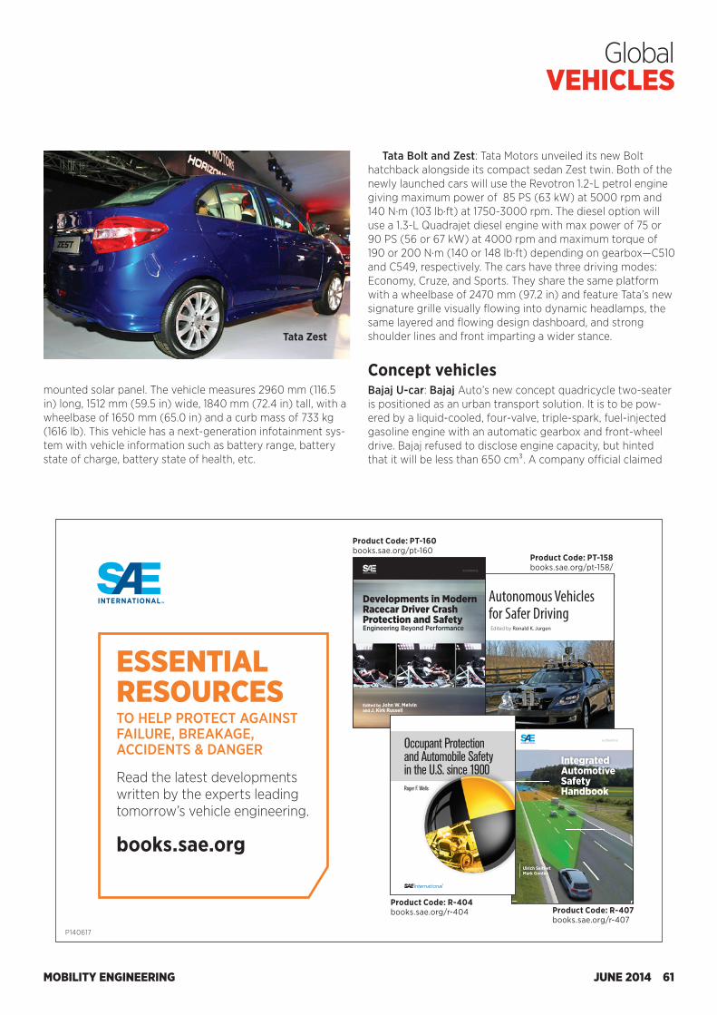
MOBILITY ENGINEERING JUNE 2014 61
Global VEHICLES
mounted solar panel. The vehicle measures 2960 mm (116.5 in) long, 1512 mm (59.5 in) wide, 1840 mm (72.4 in) tall, with a wheelbase of 1650 mm (65.0 in) and a curb mass of 733 kg (1616 lb). This vehicle has a next-generation infotainment sys-tem with vehicle information such as battery range, battery state of charge, battery state of health, etc.
Tata Zest
Tata Bolt and Zest: Tata Motors unveiled its new Bolt hatchback alongside its compact sedan Zest twin. Both of the newly launched cars will use the Revotron 1.2-L petrol engine giving maximum power of 85 PS (63 kW) at 5000 rpm and 140 N·m (103 lb·ft) at 1750-3000 rpm. The diesel option will use a 1.3-L Quadrajet diesel engine with max power of 75 or 90 PS (56 or 67 kW) at 4000 rpm and maximum torque of 190 or 200 N·m (140 or 148 lb·ft) depending on gearbox—C510 and C549, respectively. The cars have three driving modes: Economy, Cruze, and Sports. They share the same platform with a wheelbase of 2470 mm (97.2 in) and feature Tata’s new signature grille visually flowing into dynamic headlamps, the same layered and flowing design dashboard, and strong shoulder lines and front imparting a wider stance.
Concept vehiclesBajaj U-car: Bajaj Auto’s new concept quadricycle two-seater is positioned as an urban transport solution. It is to be pow-ered by a liquid-cooled, four-valve, triple-spark, fuel-injected gasoline engine with an automatic gearbox and front-wheel drive. Bajaj refused to disclose engine capacity, but hinted that it will be less than 650 cm³. A company official claimed
EssEntial REsouRcEs To Help proTecT AgAinsT FAilure, BreAkAge, AccidenTs & dAnger
Read the latest developments written by the experts leading tomorrow’s vehicle engineering. books.sae.org
PT-158
JurgenAutonom
ous Vehicles for Safer Driving
Autonomous Vehicles for Safer DrivingEdited by Ronald K. Jurgen
Autonomous Vehicles for Safer DrivingEdited by Ronald K. Jurgen
Progress In Technology serIesProgress In Technology serIes
Self-driving cars are no longer in the realm of science
fiction, thanks to the integration of numerous automotive
technologies that have matured over many years.
Technologies such as adaptive cruise control, forward
collision warning, lane departure warning, and V2V/V2I
communications are being merged into one complex system.
The papers in this compendium were carefully selected to
bring the reader up to date on successful demonstrations
of autonomous vehicles, ongoing projects, and what the
future may hold for this technology. It is divided into three
sections: overview, major design and test collaborations, and a
sampling of autonomous vehicle research projects.
This book will be of interest to a wide range of readers:
engineers at automakers and electronic component suppliers;
software engineers; computer systems analysts and architects;
academics and researchers within the electronics, computing,
and automotive industries; legislators, managers, and other
decision-makers in the government highway sector; traffic
safety professionals; and insurance and legal practitioners.
About the editorAfter graduating from Rensselaer Polytechnic Institute with
a BEE, Ronald K. Jurgen held various technical magazine
editorial staff positions, including 30 years with IEEE
Spectrum. Now retired, he is the editor of the Automotive
Electronics Handbook and the Digital Consumer Electronics
Handbook, and assistant editor of the Electronics Engineers’
Handbook, Fourth Edition. He is also the editor of more than
a dozen SAE International books on automotive electronics.
Integrated Automotive Safety HandbookUlrich Sei� ert and Mark Gonter
Despite improved vehicle safety, more than 1.2 million fatalities still occur each year on roadways worldwide. Thus, the need to continue improving vehicle and road safety remains.
New technologies in sensors and electronic control units, and the growing knowledge of car-to-car and car-to-infrastructure technologies have led to a fusion of the previously separated areas of accident avoidance (popularly known as active safety) and mitigation of injuries (popularly known as passive safety) into the newer concept of integrated vehicle safety.
This book takes a unique and comprehensive approach to describing all areas of vehicle safety: accident avoidance, pre-crash, mitigation of injuries, and post-crash technologies, providing a solutions-based perspective of integrated vehicle safety. Also covered are accident investigation and worldwide legislation as they apply to integrated vehicle safety. The man-machine interface, biomechanics and development and simulation techniques are also key concepts that are thoroughly described. Special attention is given to driver assistance systems and to compatibility in car-to-car crashes and pedestrian protection.
About the AuthorsProfessor Dr.-Ing. Ulrich Sei� ert is the acting chairman of WiTech Engineering GmbH and serves on the boards of directors for ITS Niedersachsen, VDI Vehicle Technology, FEV GmbH, WOCO, and Ihlemann AG. He is a member of the Helmholtz Senat, Royal
Swedish Academy of Engineering Sciences, and Acatech. He is a former board member for R&D at Volkswagen AG in Germany.
Dr. Mark Gonter is head of the integrated safety and light research group at Volkswagen. Since beginning at VW in 1999, he has served as head of integrated safety, project manager of adaptive occupant safety, accident researcher, and lecturer
at the Autouni of Volkswagen. He is professor of integrated vehicle safety at the University of Braunschweig and holds a Doctor of Engineering in intelligent restraint systems from Dresden University of Technology.
IntegratedAutomotive SafetyHandbook
Ulrich Sei� ertMark Gonter
Sei� ertGonter
Integrated Autom
otive Safety Handbook
R-407
AUTOMOTIVE
Developm
ents in Modern Racecar D
river Crash Protection and Safety - Engineering Beyond Perform
ance
Developments in Modern Racecar Driver Crash Protection and Safety Engineering Beyond Performance
Developments in Modern Racecar Driver Crash Protection and SafetyEngineering Beyond Performance Edited by John W. Melvin and J. Kirk Russell
This compendium comprises selected technical papers that document the development and implementation of key motorsports safety technologies now in use. It is intended to provide racing professionals and enthusiasts with a concise overview of the significant engineering developments in motorsports driver safety that has occurred during the past two decades.
The 13 papers chosen for this compendium were published between 1990 and 2013 and reflect landmark safety studies and developments of that time. Eleven of the papers were published by SAE International, and two were presented at the Stapp Car Crash Conference. The papers chosen are focused on the following topics:• Crashtestingsimulations• Humancrashinjuryandsurvival• Reducingdriverinjuryinseverecrashes• Headandneckrestraints,includingtheHANSdevice• Racecarseats• Restraintsystems• Tracksafetyandbarriersystems
The final paper in this compendium is a study on the detailed performance of restraint systems and seats in examples of severe stock car crashes. The paper represents a succinct example of modern crash investigation of racing crashes with crashrecordingdata,detailedinjuryanalysis,andprotectivesystem performance.
The progress in motorsports safety, as described in this compendium, has been dramatically effective in reducingdriverinjuriesatthetoplevelsofmotorsports.Unfortunately, this is not true at the lower levels of motorsports, where drivers continue to suffer preventable injuriesandfatalities.Drivereducationbasedontheprinciples and features of the work presented in this compendium is an urgent and unsolved issue. Many drivers do not recognize that all racing drivers have the same crash protection needs.
About the Editors John W. Melvin has researched the biomechanicsofimpactinjuryanditsapplication to the protection of vehicle occupants in crashes for over 44 years. Hisresearchonracecardriversafetyover the past 20 years has made him one of the world’s foremost authorities on racecar driver crash protection. Since
retiring from General Motors Corporation, he has served as a consultant to many racing organizations such as CART, IRL,NASCAR,andtheSFIFoundation.Heisanindependentconsultantonthebiomechanicsofcrashinjuryandracecardrivercrashprotection,andanadjunctprofessorofbiomedicalengineeringatWayneStateUniversity.Dr.MelvinholdsaPh.D.intheoreticalandappliedmechanicsfrom the University of Illinois.
A veteran of motorsports for more than 50 years, Kirk Russell started his competition activities as a crew member and official in the Sports Car Club of America and hill climbing events and assisted in the preparationoftheNationalHotRodAssociation’sgasclassracecars.Hewashired at CART as technical director and during a career of more than 30 years,
held additional responsibilities including writing rules, event organization, logistics, and safety. Mr. Russell is a founding member of SAE’s Motorsports Engineering Activity and NationalFireProtectionAssociation’sNFPA610motorsportcommittee.Heconsultsonmotorsportsafety,facilities,eventorganization, and technical issues.
Melvin/Russell
Edited by John W. Melvin and J. Kirk Russell
PT-160
AUTOMOTIVE
Roger F. Wells
Roger F. WellsOccupant Protection and Automobile Safety in the U.S. since 1900
The quest for innovation and speed in the first 60 years of the automobile’s development overshadowed efforts made to protect drivers and passengers. However, safety became a more important facet of motorized travel as more drivers took to the roads and serious injuries and deaths attributed to automobiles began to increase rapidly.
Automobile fatalities seemed an inevitable consequence of progress, and it was not until the mid-1920s that the U.S. government tried to understand and stem the increasing number of road accidents and deaths. All involved parties were to some extent responsible for not improving the situation up to that point: drivers for their lack of concern about safety, politicians for failing to mandate adequate safety rules, and the automobile industry for not implementing available technologies to save lives.
This book is an exploration of ingenuity, entrepreneurship, and technical skill that have resulted in today’s advanced and safe automobiles. It provides a historical review of safety features appearing on passenger cars that have been produced for sale in the U.S. from 1900 to the present. A main theme throughout is the impact the automobile has made on society, with particular emphasis on accidents and loss of life. Another theme involves the technological advances that have contributed to safer driving.
About the AuthorBorn in England, Roger Wells served as an engineer apprentice with Hawker Siddely Aviation and completed his undergraduate education in mechanical engineering. Early in his career he
was an engineer for the United Kingdom Ministries of Technology and Defence where he managed testing facilities for development of military fighting vehicles and aircraft fuel systems.
Later, Wells worked on microprocessor-controlled engine diagnostic systems, airbag crash protection systems, and development of sensors for passenger vehicle stability control. He has served in various engineering and executive management roles with United Technologies, TRW Automotive, and BEI Technologies.
Dr. Wells holds MBA and PhD degrees in business management.
R-404
Occupant Protection and Automobile Safety in the U.S. since 1900
Wells
Occupant Protection and Automobile Safety in the U.S. since 1900
Product Code: PT-160books.sae.org/pt-160
Product Code: R-404books.sae.org/r-404
Product Code: PT-158books.sae.org/pt-158/
Product Code: R-407books.sae.org/r-407
P140617
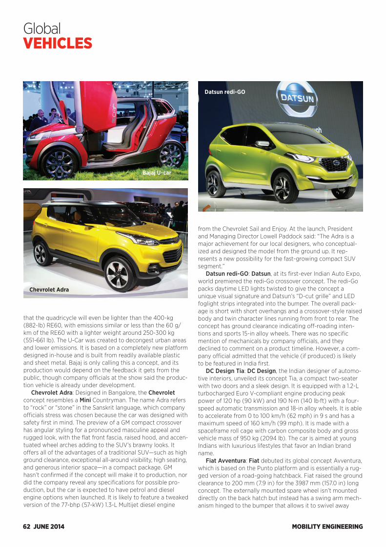
MOBILITY ENGINEERING62 JUNE 2014
Global VEHICLES
Datsun redi-GO
Bajaj U-car
Chevrolet Adra
that the quadricycle will even be lighter than the 400-kg (882-lb) RE60, with emissions similar or less than the 60 g/km of the RE60 with a lighter weight around 250-300 kg (551-661 lb). The U-Car was created to decongest urban areas and lower emissions. It is based on a completely new platform designed in-house and is built from readily available plastic and sheet metal. Bajaj is only calling this a concept, and its production would depend on the feedback it gets from the public, though company officials at the show said the produc-tion vehicle is already under development.
Chevrolet Adra: Designed in Bangalore, the Chevrolet concept resembles a Mini Countryman. The name Adra refers to “rock” or “stone” in the Sanskrit language, which company officials stress was chosen because the car was designed with safety first in mind. The preview of a GM compact crossover has angular styling for a pronounced masculine appeal and rugged look, with the flat front fascia, raised hood, and accen-tuated wheel arches adding to the SUV’s brawny looks. It offers all of the advantages of a traditional SUV—such as high ground clearance, exceptional all-around visibility, high seating, and generous interior space—in a compact package. GM hasn’t confirmed if the concept will make it to production, nor did the company reveal any specifications for possible pro-duction, but the car is expected to have petrol and diesel engine options when launched. It is likely to feature a tweaked version of the 77-bhp (57-kW) 1.3-L Multijet diesel engine
from the Chevrolet Sail and Enjoy. At the launch, President and Managing Director Lowell Paddock said: “The Adra is a major achievement for our local designers, who conceptual-ized and designed the model from the ground up. It rep-resents a new possibility for the fast-growing compact SUV segment.”
Datsun redi-GO: Datsun, at its first-ever Indian Auto Expo, world premiered the redi-Go crossover concept. The redi-Go packs daytime LED lights twisted to give the concept a unique visual signature and Datsun’s “D-cut grille” and LED foglight strips integrated into the bumper. The overall pack-age is short with short overhangs and a crossover-style raised body and twin character lines running from front to rear. The concept has ground clearance indicating off-roading inten-tions and sports 15-in alloy wheels. There was no specific mention of mechanicals by company officials, and they declined to comment on a product timeline. However, a com-pany official admitted that the vehicle (if produced) is likely to be featured in India first.
DC Design Tia: DC Design, the Indian designer of automo-tive interiors, unveiled its concept Tia, a compact two-seater with two doors and a sleek design. It is equipped with a 1.2-L turbocharged Euro V-compliant engine producing peak power of 120 hp (90 kW) and 190 N·m (140 lb·ft) with a four-speed automatic transmission and 18-in alloy wheels. It is able to accelerate from 0 to 100 km/h (62 mph) in 9 s and has a maximum speed of 160 km/h (99 mph). It is made with a spaceframe roll cage with carbon composite body and gross vehicle mass of 950 kg (2094 lb). The car is aimed at young Indians with luxurious lifestyles that favor an Indian brand name.
Fiat Avventura: Fiat debuted its global concept Avventura, which is based on the Punto platform and is essentially a rug-ged version of a road-going hatchback. Fiat raised the ground clearance to 200 mm (7.9 in) for the 3987 mm (157.0 in) long concept. The externally mounted spare wheel isn’t mounted directly on the back hatch but instead has a swing arm mech-anism hinged to the bumper that allows it to swivel away
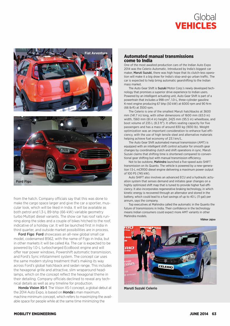
MOBILITY ENGINEERING JUNE 2014 63
Global VEHICLES
from the hatch. Company officials say that this was done to make the cargo space larger and give the car a sportier, mus-cular look, which will be liked in India. It will be available as both petrol and 1.3-L 89-bhp (66-kW) variable geometry turbo Multijet diesel variants. The show car has roof rails run-ning along the sides and a couple of bikes hitched to the roof, indicative of a holiday car. It will be launched first in India in third quarter, and outside market possibilities are in process.
Ford Figo: Ford showcases an all-new global small car model, codenamed B562, with the name of Figo in India, but in other markets it will be called Ka. The car is expected to be powered by 1.0-L turbocharged EcoBoost engine and will offer rear power windows, Powershift automatic transmission, and Ford’s Sync infotainment system. The concept car uses the same modern styling treatment that’s making its way across Ford’s global hatchback and sedan range. This includes the hexagonal grille and attractive, slim wraparound head-lamps, which on the concept reflect the hexagonal theme in their detailing. Company officials declined to reveal any tech-nical details as well as any timeline for production.
Honda Vision XS-1: The Vision XS-1 concept, a global debut at the 2014 Auto Expo, is based on Honda’s man maximum, machine minimum concept, which refers to maximizing the avail-able space for people while at the same time minimizing the
Fiat AvventuraAutomated manual transmissions come to IndiaOne of the most awaited production cars of the Indian Auto Expo 2014 was the Celerio Automatic. Introduced by India’s biggest car maker, Maruti Suzuki, there was high hope that its clutch-less opera-tion will make it a big draw for India’s stop-and-go urban traffic. The car is expected to help bring automatic gearshifting to the Indian mass market.
The Auto Gear Shift is Suzuki Motor Corp.’s newly developed tech-nology that promises a superior drive experience to Indian users. Powered by an intelligent actuating unit, Auto Gear Shift is part of a powertrain that includes a 998-cm³, 1.0-L, three-cylinder gasoline K-next engine producing 67 bhp (50 kW) at 6000 rpm and 90 N·m (66 lb·ft) at 3500 rpm.
The Celerio is one of the smallest Maruti hatchbacks at 3600 mm (141.7 in) long, with other dimensions of 1600 mm (63.0 in) width, 1560 mm (61.4 in) height, 2425 mm (95.5 in) wheelbase, and boot volume of 235 L (8.3 ft³). It offers seating capacity for five passengers and has a mass of around 830 kg (1830 lb). Weight optimization was an important consideration to enhance fuel effi-ciency, with the use of high tensile steel and alternative materials helping achieve fuel economy of 23.1 km/L.
The Auto Gear Shift automated manual transmission (AMT) is equipped with an intelligent shift control actuator for smooth gear changes by coordinating clutch and shift operations in sync. Maruti Suzuki claims that shifting time is shortened compared to conven-tional gear shifting but with manual transmission efficiency.
Not to be outdone, Mahindra launched a five-speed auto SHIFT transmission on its Quanto. The vehicle is powered by a new-genera-tion 1.5-L mCR100 diesel engine delivering a maximum power output of 100 PS (745 kW).
Auto SHIFT also involves an advanced ECU and a hydraulic actu-ation system that senses demand and initiates gear changes on a highly optimized shift map that is tuned to provide higher fuel effi-ciency. It also incorporates regenerative braking technology, in which kinetic energy is recovered through an alternator and stored in the battery, which could lead to a fuel savings of up to 40 L (11 gal) per annum, says the company.
Top executives at Mahindra called the automatic in the Quanto the future of transmissions in India. Their confidence in the technology means Indian consumers could expect more AMT variants in other Mahindra models.
Vibhor Jajoo
Maruti Suzuki Celerio
Ford Figo
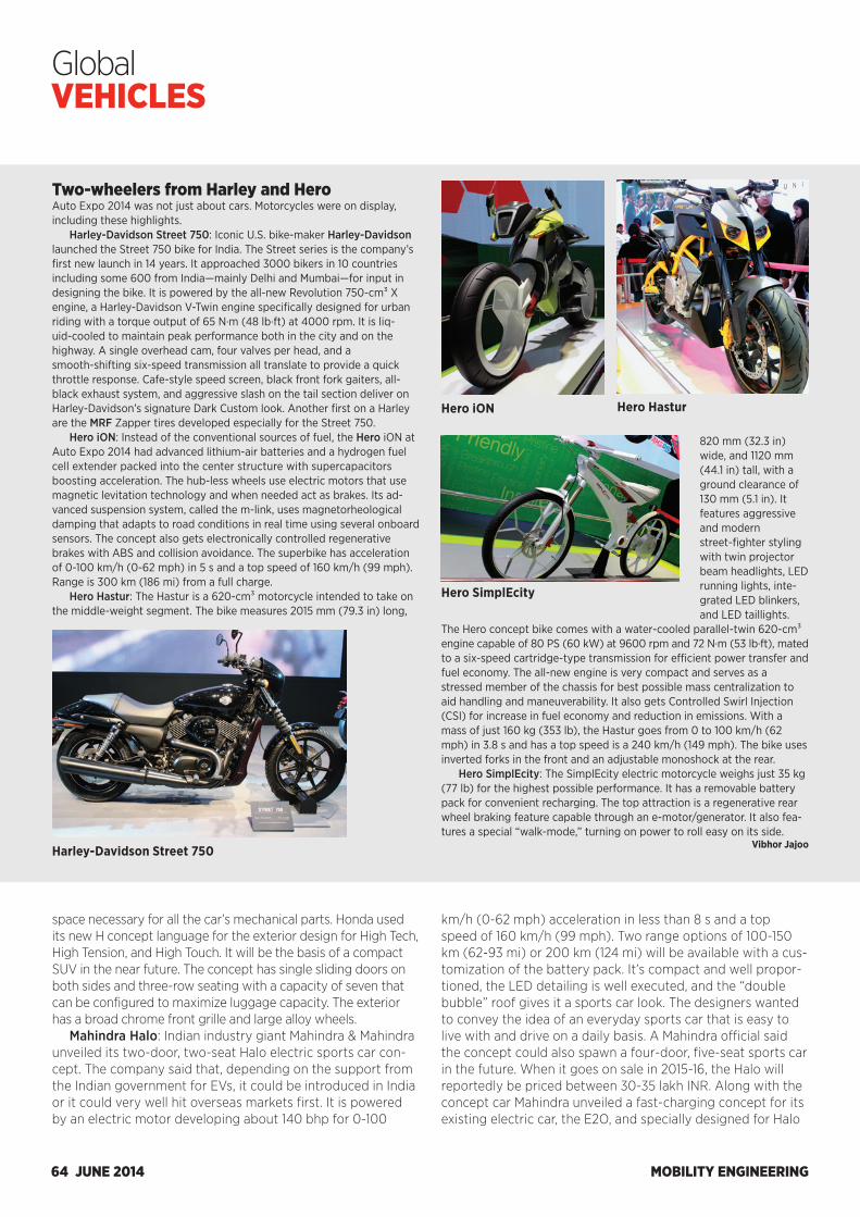
MOBILITY ENGINEERING64 JUNE 2014
Global VEHICLES
space necessary for all the car’s mechanical parts. Honda used its new H concept language for the exterior design for High Tech, High Tension, and High Touch. It will be the basis of a compact SUV in the near future. The concept has single sliding doors on both sides and three-row seating with a capacity of seven that can be configured to maximize luggage capacity. The exterior has a broad chrome front grille and large alloy wheels.
Mahindra Halo: Indian industry giant Mahindra & Mahindra unveiled its two-door, two-seat Halo electric sports car con-cept. The company said that, depending on the support from the Indian government for EVs, it could be introduced in India or it could very well hit overseas markets first. It is powered by an electric motor developing about 140 bhp for 0-100
km/h (0-62 mph) acceleration in less than 8 s and a top speed of 160 km/h (99 mph). Two range options of 100-150 km (62-93 mi) or 200 km (124 mi) will be available with a cus-tomization of the battery pack. It’s compact and well propor-tioned, the LED detailing is well executed, and the “double bubble” roof gives it a sports car look. The designers wanted to convey the idea of an everyday sports car that is easy to live with and drive on a daily basis. A Mahindra official said the concept could also spawn a four-door, five-seat sports car in the future. When it goes on sale in 2015-16, the Halo will reportedly be priced between 30-35 lakh INR. Along with the concept car Mahindra unveiled a fast-charging concept for its existing electric car, the E2O, and specially designed for Halo
Two-wheelers from Harley and HeroAuto Expo 2014 was not just about cars. Motorcycles were on display, including these highlights.
Harley-Davidson Street 750: Iconic U.S. bike-maker Harley-Davidson launched the Street 750 bike for India. The Street series is the company’s first new launch in 14 years. It approached 3000 bikers in 10 countries including some 600 from India—mainly Delhi and Mumbai—for input in designing the bike. It is powered by the all-new Revolution 750-cm³ X engine, a Harley-Davidson V-Twin engine specifically designed for urban riding with a torque output of 65 N·m (48 lb·ft) at 4000 rpm. It is liq-uid-cooled to maintain peak performance both in the city and on the highway. A single overhead cam, four valves per head, and a smooth-shifting six-speed transmission all translate to provide a quick throttle response. Cafe-style speed screen, black front fork gaiters, all-black exhaust system, and aggressive slash on the tail section deliver on Harley-Davidson’s signature Dark Custom look. Another first on a Harley are the MRF Zapper tires developed especially for the Street 750.
Hero iON: Instead of the conventional sources of fuel, the Hero iON at Auto Expo 2014 had advanced lithium-air batteries and a hydrogen fuel cell extender packed into the center structure with supercapacitors boosting acceleration. The hub-less wheels use electric motors that use magnetic levitation technology and when needed act as brakes. Its ad-vanced suspension system, called the m-link, uses magnetorheological damping that adapts to road conditions in real time using several onboard sensors. The concept also gets electronically controlled regenerative brakes with ABS and collision avoidance. The superbike has acceleration of 0-100 km/h (0-62 mph) in 5 s and a top speed of 160 km/h (99 mph). Range is 300 km (186 mi) from a full charge.
Hero Hastur: The Hastur is a 620-cm³ motorcycle intended to take on the middle-weight segment. The bike measures 2015 mm (79.3 in) long,
820 mm (32.3 in) wide, and 1120 mm (44.1 in) tall, with a ground clearance of 130 mm (5.1 in). It features aggressive and modern street-fighter styling with twin projector beam headlights, LED running lights, inte-grated LED blinkers, and LED taillights.
The Hero concept bike comes with a water-cooled parallel-twin 620-cm³ engine capable of 80 PS (60 kW) at 9600 rpm and 72 N·m (53 lb·ft), mated to a six-speed cartridge-type transmission for efficient power transfer and fuel economy. The all-new engine is very compact and serves as a stressed member of the chassis for best possible mass centralization to aid handling and maneuverability. It also gets Controlled Swirl Injection (CSI) for increase in fuel economy and reduction in emissions. With a mass of just 160 kg (353 lb), the Hastur goes from 0 to 100 km/h (62 mph) in 3.8 s and has a top speed is a 240 km/h (149 mph). The bike uses inverted forks in the front and an adjustable monoshock at the rear.
Hero SimplEcity: The SimplEcity electric motorcycle weighs just 35 kg (77 lb) for the highest possible performance. It has a removable battery pack for convenient recharging. The top attraction is a regenerative rear wheel braking feature capable through an e-motor/generator. It also fea-tures a special “walk-mode,” turning on power to roll easy on its side.
Vibhor JajooHarley-Davidson Street 750
Hero iON Hero Hastur
Hero SimplEcity
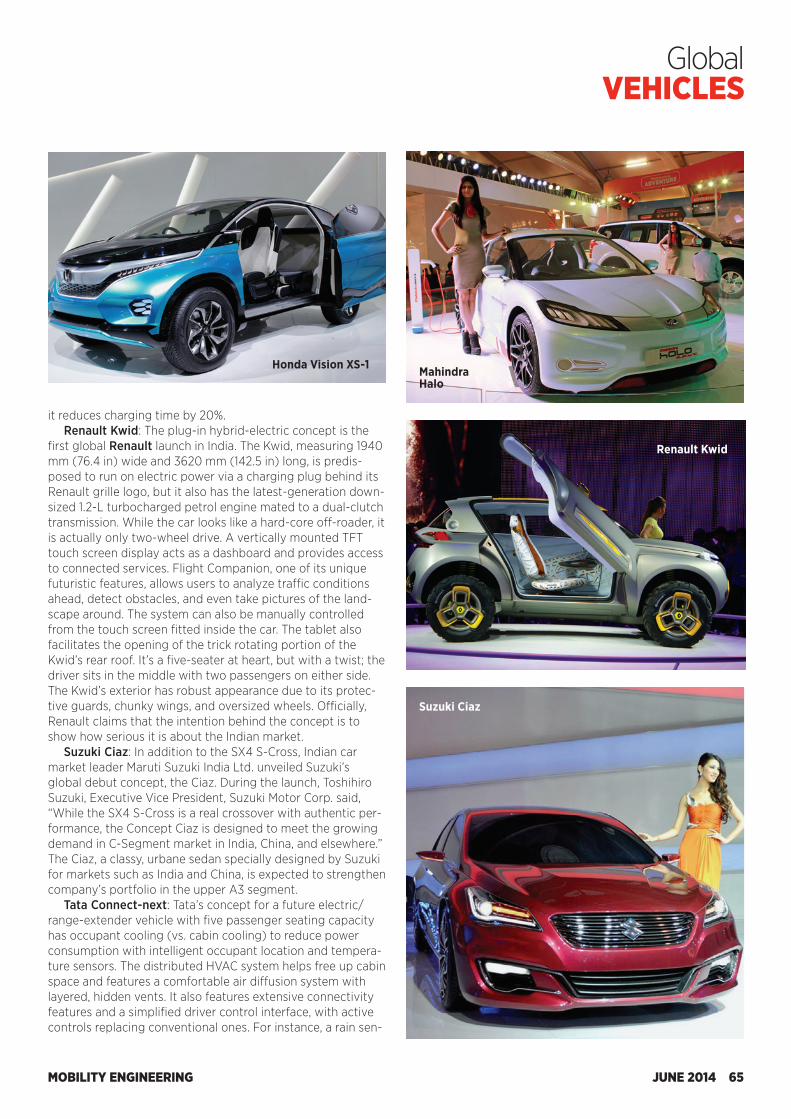
MOBILITY ENGINEERING JUNE 2014 65
Global VEHICLES
it reduces charging time by 20%.Renault Kwid: The plug-in hybrid-electric concept is the
first global Renault launch in India. The Kwid, measuring 1940 mm (76.4 in) wide and 3620 mm (142.5 in) long, is predis-posed to run on electric power via a charging plug behind its Renault grille logo, but it also has the latest-generation down-sized 1.2-L turbocharged petrol engine mated to a dual-clutch transmission. While the car looks like a hard-core off-roader, it is actually only two-wheel drive. A vertically mounted TFT touch screen display acts as a dashboard and provides access to connected services. Flight Companion, one of its unique futuristic features, allows users to analyze traffic conditions ahead, detect obstacles, and even take pictures of the land-scape around. The system can also be manually controlled from the touch screen fitted inside the car. The tablet also facilitates the opening of the trick rotating portion of the Kwid’s rear roof. It’s a five-seater at heart, but with a twist; the driver sits in the middle with two passengers on either side. The Kwid’s exterior has robust appearance due to its protec-tive guards, chunky wings, and oversized wheels. Officially, Renault claims that the intention behind the concept is to show how serious it is about the Indian market.
Suzuki Ciaz: In addition to the SX4 S-Cross, Indian car market leader Maruti Suzuki India Ltd. unveiled Suzuki’s global debut concept, the Ciaz. During the launch, Toshihiro Suzuki, Executive Vice President, Suzuki Motor Corp. said, “While the SX4 S-Cross is a real crossover with authentic per-formance, the Concept Ciaz is designed to meet the growing demand in C-Segment market in India, China, and elsewhere.” The Ciaz, a classy, urbane sedan specially designed by Suzuki for markets such as India and China, is expected to strengthen company’s portfolio in the upper A3 segment.
Tata Connect-next: Tata’s concept for a future electric/range-extender vehicle with five passenger seating capacity has occupant cooling (vs. cabin cooling) to reduce power consumption with intelligent occupant location and tempera-ture sensors. The distributed HVAC system helps free up cabin space and features a comfortable air diffusion system with layered, hidden vents. It also features extensive connectivity features and a simplified driver control interface, with active controls replacing conventional ones. For instance, a rain sen-
Honda Vision XS-1 Mahindra Halo
Renault Kwid
Suzuki Ciaz
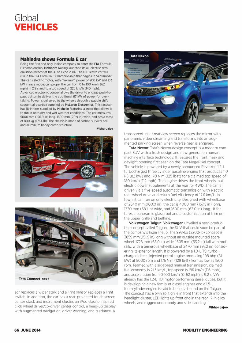
MOBILITY ENGINEERING66 JUNE 2014
Global VEHICLES
transparent inner rearview screen replaces the mirror with panoramic video streaming and transforms into an aug-mented parking screen when reverse gear is engaged.
Tata Nexon: Tata’s Nexon design concept is a modern com-pact SUV with a fresh design and new-generation human machine interface technology. It features the front mask and daylight opening first seen on the Tata MegaPixel concept. The vehicle is powered by a newly announced Revotron 1.2-L turbocharged three cylinder gasoline engine that produces 110 PS (82 kW) and 170 N·m (125 lb·ft) for a claimed top speed of 180 km/h (112 mph). The engine drives the front wheels, but electric power supplements at the rear for 4WD. The car is driven via a five-speed automatic transmission with electric rear-wheel drive and return fuel efficiency of 17.6 km/L. In town, it can run on only electricity. Designed with wheelbase of 2540 mm (100.0 in), the car is 4000 mm (157.5 in) long, 1730 mm (68.1 in) wide, and 1600 mm (63.0 in) long. It fea-tures a panoramic glass roof and a customization of trim on the upper grille and beltline.
Volkswagen Taigun: Volkswagen unveiled a near-produc-tion concept called Taigun, the SUV that could soon be part of the company’s India lineup. The 998-kg (2200-lb) concept is 3859 mm (151.9 in) long without an outside mounted spare wheel, 1728 mm (68.0 in) wide, 1605 mm (63.2 in) tall with roof rails, with a generous wheelbase of 2470 mm (97.2 in) consid-ering its exterior length. It is powered by a 1.0-L TSI turbo-charged direct-injected petrol engine producing 108 bhp (81 kW) at 5000 rpm and 175 N·m (129 lb·ft) from as low as 1500 rpm. Teamed with a six-speed manual transmission, claimed fuel economy is 21.3 km/L, top speed is 186 km/h (116 mph), and acceleration from 0-100 km/h (0-62 mph) is 9.2 s. VW already has the 1.2-L TDI motor performing diesel duties, but it is developing a new family of diesel engines and a 1.5-L four-cylinder engine is said to be India bound on the Taigun. The concept has a twin split grille in front that extends into the headlight cluster, LED lights up front and in the rear, 17-in alloy wheels, and rugged under body and side cladding.
Vibhor Jajoo
Tata Connect-next
Tata NexonMahindra shows Formula E carBeing the first and only Indian company to enter the FIA Formula E championship, Mahindra Racing launched its all-electric zero emission racecar at the Auto Expo 2014. The M1 Electro car will run in the FIA Formula E Championship that begins in September. The car’s electric motor, with maximum power of 200 kW and 133 kW in race mode, can propel the car from 0 to 100 km/h (62 mph) in 2.9 s and to a top speed of 225 km/h (140 mph). Advanced electronic control allows the driver to engage push-to-pass button to deliver the additional 67 kW of power for over-taking. Power is delivered to the wheels through a paddle shift sequential gearbox supplied by McLaren Electronics. This racecar has 18-in tires supplied by Michelin featuring a tread that allows it to run in both dry and wet weather conditions. The car measures 5000 mm (196.9 in) long, 1800 mm (70.9 in) wide, and has a mass of 800 kg (1764 lb). The chassis is made of carbon survival cell and aluminum honey comb structure.
Vibhor Jajoo
sor replaces a wiper stalk and a light sensor replaces a light switch. In addition, the car has a rear-projected touch screen center stack and instrument cluster, an iPod classic-inspired click wheel driver/co-driver center control, a head-up display with augmented navigation, driver warning, and guidance. A
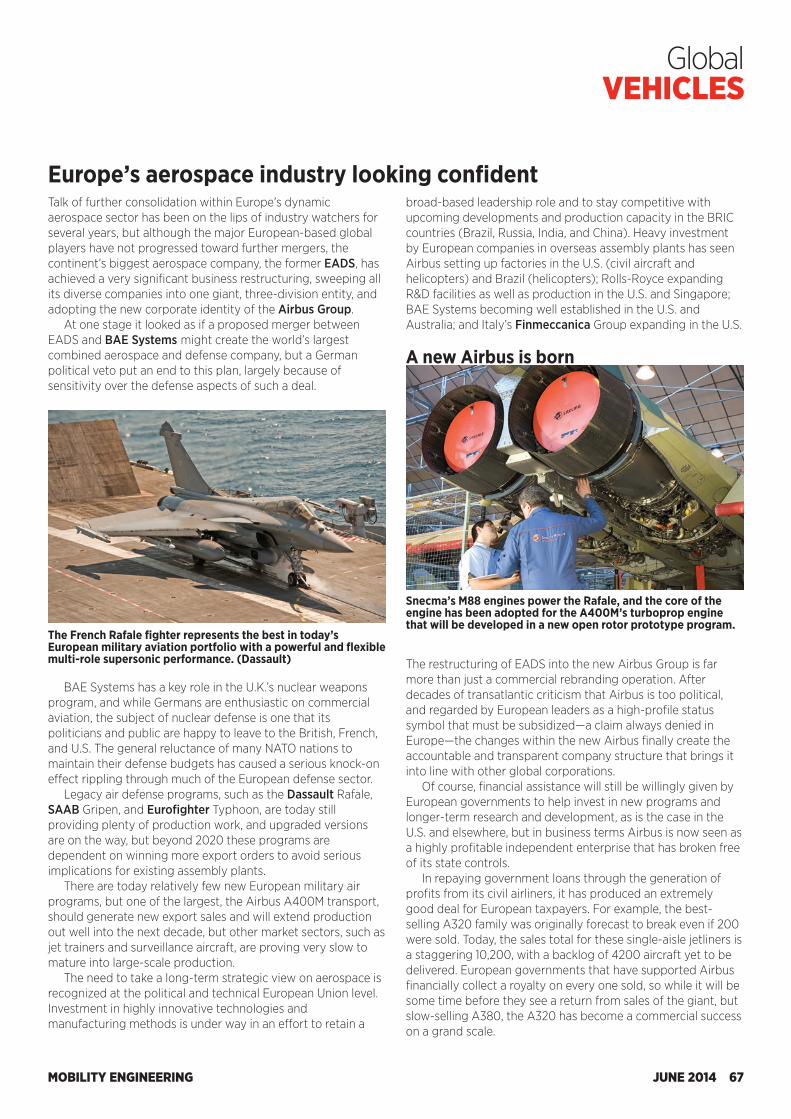
MOBILITY ENGINEERING JUNE 2014 67
Global VEHICLES
Talk of further consolidation within Europe’s dynamic aerospace sector has been on the lips of industry watchers for several years, but although the major European-based global players have not progressed toward further mergers, the continent’s biggest aerospace company, the former EADS, has achieved a very significant business restructuring, sweeping all its diverse companies into one giant, three-division entity, and adopting the new corporate identity of the Airbus Group.
At one stage it looked as if a proposed merger between EADS and BAE Systems might create the world’s largest combined aerospace and defense company, but a German political veto put an end to this plan, largely because of sensitivity over the defense aspects of such a deal.
broad-based leadership role and to stay competitive with upcoming developments and production capacity in the BRIC countries (Brazil, Russia, India, and China). Heavy investment by European companies in overseas assembly plants has seen Airbus setting up factories in the U.S. (civil aircraft and helicopters) and Brazil (helicopters); Rolls-Royce expanding R&D facilities as well as production in the U.S. and Singapore; BAE Systems becoming well established in the U.S. and Australia; and Italy’s Finmeccanica Group expanding in the U.S. A new Airbus is born
Europe’s aerospace industry looking confident
BAE Systems has a key role in the U.K.’s nuclear weapons program, and while Germans are enthusiastic on commercial aviation, the subject of nuclear defense is one that its politicians and public are happy to leave to the British, French, and U.S. The general reluctance of many NATO nations to maintain their defense budgets has caused a serious knock-on effect rippling through much of the European defense sector.
Legacy air defense programs, such as the Dassault Rafale, SAAB Gripen, and Eurofighter Typhoon, are today still providing plenty of production work, and upgraded versions are on the way, but beyond 2020 these programs are dependent on winning more export orders to avoid serious implications for existing assembly plants.
There are today relatively few new European military air programs, but one of the largest, the Airbus A400M transport, should generate new export sales and will extend production out well into the next decade, but other market sectors, such as jet trainers and surveillance aircraft, are proving very slow to mature into large-scale production.
The need to take a long-term strategic view on aerospace is recognized at the political and technical European Union level. Investment in highly innovative technologies and manufacturing methods is under way in an effort to retain a
The restructuring of EADS into the new Airbus Group is far more than just a commercial rebranding operation. After decades of transatlantic criticism that Airbus is too political, and regarded by European leaders as a high-profile status symbol that must be subsidized—a claim always denied in Europe—the changes within the new Airbus finally create the accountable and transparent company structure that brings it into line with other global corporations.
Of course, financial assistance will still be willingly given by European governments to help invest in new programs and longer-term research and development, as is the case in the U.S. and elsewhere, but in business terms Airbus is now seen as a highly profitable independent enterprise that has broken free of its state controls.
In repaying government loans through the generation of profits from its civil airliners, it has produced an extremely good deal for European taxpayers. For example, the best-selling A320 family was originally forecast to break even if 200 were sold. Today, the sales total for these single-aisle jetliners is a staggering 10,200, with a backlog of 4200 aircraft yet to be delivered. European governments that have supported Airbus financially collect a royalty on every one sold, so while it will be some time before they see a return from sales of the giant, but slow-selling A380, the A320 has become a commercial success on a grand scale.
The French Rafale fighter represents the best in today’s European military aviation portfolio with a powerful and flexible multi-role supersonic performance. (Dassault)
Snecma’s M88 engines power the Rafale, and the core of the engine has been adopted for the A400M’s turboprop engine that will be developed in a new open rotor prototype program.
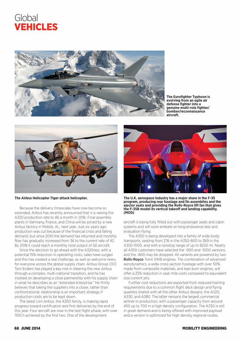
MOBILITY ENGINEERING68 JUNE 2014
Global VEHICLES
Because the delivery timescales have now become so extended, Airbus has recently announced that it is raising the A320 production rate to 46 a month in 2016. Final assembly plants in Germany, France, and China will be joined by a new Airbus factory in Mobile, AL, next year. Just six years ago production was cut because of the financial crisis and falling demand, but since 2010 the demand has returned and monthly flow has gradually increased from 36 to the current rate of 42. By 2018 it could reach a monthly total output of 50 aircraft.
Since the decision to go ahead with the A320neo, with a potential 15% reduction in operating costs, sales have surged and this has created a real challenge, as well as welcome news, for everyone across the global supply chain. Airbus Group CEO Tom Enders has played a key role in steering the new Airbus through a complex, multi-national transition, and he has insisted on developing a close partnership with his supply chain in what he describes as an “extended enterprise.” He firmly believes that taking the suppliers into a closer, rather than confrontational, relationship is an important strategy if production costs are to be kept down.
The latest civil Airbus, the A350 family, is making rapid progress toward certification and first deliveries by the end of this year. Four aircraft are now in the test flight phase, with over 1100 h achieved by the first two. One of the development
aircraft is being fully fitted out with passenger seats and cabin systems and will soon embark on long endurance test and evaluation flying.
The A350 is being developed into a family of wide-body transports, seating from 276 in the A350-800 to 369 in the A350-1000, and with a nonstop range of up to 8250 mi. Nearly all A350 customers have selected the -900 and -1000 versions, and the -800 may be dropped. All variants are powered by two Rolls-Royce Trent XWB engines. The combination of advanced aerodynamics, a wide cross-section fuselage with over 50% made from composite materials, and lean burn engines, will offer a 25% reduction in seat mile costs compared to equivalent size current jets.
Further cost reductions are expected from reduced training requirements due to a common flight deck design and flying qualities shared with all the other Airbus designs, the A320, A330, and A380. The latter remains the largest commercial airliner in production, with a passenger capacity from around 450 up to 700 in a high density configuration. The A330 is still in great demand and is being offered with improved payload and a version is optimized for high density regional routes,
The Eurofighter Typhoon is evolving from an agile air defense fighter into a genuine multi-role fighter/bomber/reconnaissance aircraft.
The Airbus Helicopter Tiger attack helicopter. The U.K. aerospace industry has a major share in the F-35 program, producing rear fuselage and fin assemblies and the ejector seats and providing the Rolls-Royce lift fan that gives the F-35B model its vertical takeoff and landing capability. (MOD)
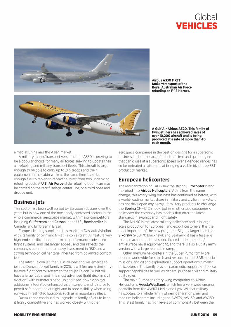
MOBILITY ENGINEERING JUNE 2014 69
Global VEHICLES
aimed at China and the Asian market. A military tanker/transport version of the A330 is proving to
be a popular choice for many air forces seeking to update their air refueling and military transport fleets. This aircraft is large enough to be able to carry up to 265 troops and their equipment in the cabin while at the same time it carries enough fuel to replenish receiver aircraft from two underwing refueling pods. A U.S. Air Force-style refueling boom can also be carried on the rear fuselage center-line, or a third hose and drogue unit. Business jets This sector has been well served by European designs over the years but is now one of the most hotly contested sectors in the whole commercial aerospace market, with major competitors including Gulfstream and Cessna in the U.S., Bombardier in Canada, and Embraer in Brazil.
Europe’s leading supplier in this market is Dassault Aviation, with its family of twin and tri-jet Falcon aircraft. All feature very high-end specifications, in terms of performance, advanced flight systems, and passenger appeal, and this reflects the company’s commitment to heavy investment in R&D and a strong technological heritage inherited from advanced combat jets.
The latest Falcon jet, the 5X, is all-new and will emerge to join the Dassault bizjet family in 2015. It will feature a similar fly-by-wire flight control system to the tri-jet Falcon 7X but will have a larger cabin and “the most advanced flight deck in civil aviation” with numerous head-up and head-down displays, additional integrated enhanced vision sensors, and features to permit safe operation at night and in poor visibility when using runways in restricted locations, such as in mountain valleys.
Dassault has continued to upgrade its family of jets to keep it highly competitive and has worked closely with other
aerospace companies in the past on designs for a supersonic business jet, but the lack of a fuel-efficient and quiet engine that can cruise at a supersonic speed over extended ranges has so far defeated all attempts at bringing a viable bizjet-size SST product to market. European helicopters The reorganization of EADS saw the strong Eurocopter brand morphed into Airbus Helicopters. Apart from the name change, this rotary wing business has continued as before, with a world-leading market share in military and civilian markets. It has not developed any heavy lift military products to challenge the Boeing CH-47 Chinook, but in all other size categories of helicopter the company has models that offer the latest standards in avionics and flight safety.
The NH-90 is the latest military helicopter and is in large-scale production for European and export customers. It is the most important of the new programs. Slightly larger than the Sikorsky S-60/70 Blackhawk and Seahawk, it has a fuselage that can accommodate a sophisticated anti-submarine/anti-surface naval equipment fit, and there is also a utility army version with a large rear cabin ramp.
Other medium helicopters in the Super Puma family are popular worldwide for search and rescue, combat SAR, special missions, and oil and exploration support operations. Smaller helicopters in the family provide paramedic support and police support capabilities as well as general purpose civil and military utility roles.
The main European rotary wing competitor to Airbus Helicopter is AgustaWestland, which has a very wide ranging portfolio from the AW101 Merlin and Lynx Wildcat military helicopters to a whole family of new generation small and medium helicopters including the AW139, AW169, and AW189. This latest family has high levels of commonality between the
Airbus A330 MRTT tanker/transport of the Royal Australian Air Force refueling an F-18 Hornet.
A Gulf Air Airbus A320. This family of twin jetliners has achieved sales of over 10,200 aircraft and is being produced at a rate of more than 40 each month.
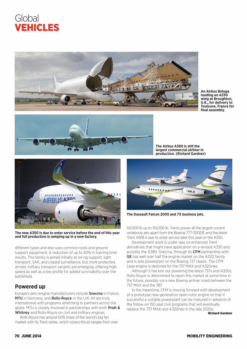
MOBILITY ENGINEERING70 JUNE 2014
Global VEHICLES
different types and also uses common tools and ground support equipment. A reduction of up to 40% in training time results. This family is aimed initially at oil-rig support, light transport, SAR, and coastal surveillance, but more protected, armed, military transport variants are emerging, offering high speed as well as a low profile for added survivability over the battlefield. Powered up Europe’s aero engine manufacturers include Snecma in France, MTU in Germany, and Rolls-Royce in the U.K. All are truly international with programs stretching to partners across the globe. MTU is closely involved in partnerships with both Pratt & Whitney and Rolls-Royce on civil and military engines.
Rolls-Royce has around 50% share of the world’s big fan market with its Trent series, which covers thrust ranges from over
An Airbus Beluga loading an A330 wing at Broughton, U.K., for delivery to Toulouse, France for final assembly.
The Airbus A380 is still the largest commercial airliner in production. (Richard Gardner)
The new A350 is due to enter service before the end of this year and full production is ramping up in a new factory.
The Dassault Falcon 200S and 7X business jets.
50,000 lb up to 110,000 lb. Trents power all the largest current widebody jets apart from the Boeing 777-300ER, and the latest Trent XWB is due to enter service later this year on the A350.
Development work is under way on enhanced Trent derivatives that might have application on a revised A330 and possibly the A380. Snecma, through its CFM partnership with GE has well over half the engine market on the A320 family and is sole powerplant on the Boeing 737 classic. The CFM Leap engine is destined for the 737 MAX and A320neo.
Although it has lost out powering the latest 737s and A320s, Rolls-Royce is determined to rejoin this market at some time in the future, possibly via a new Boeing airliner sized between the 737 MAX and the 787.
In the meantime, CFM is moving forward with development of a prototype new-generation open-rotor engine so that if successful a suitable powerplant can be matured in advance of the follow-on 150 seat civil programs that will eventually replace the 737 MAX and A320neo in the late 2020s.
Richard Gardner
COMPANIES MENTIONED
AD INDEX
Altair Engineering Pvt Ltd...........................................................................11 ................www.altairhyperworks.in
AR RF/Microwave Instrumentation ........................................................17 ................www.arworld.us/totalEMC
AR RF/Microwave Instrumentation (contact in India) ....................17 ................www.complus.in
BorgWarner Inc ..................................................................................Cover 3 ................www.borgwarner.com
Celanese ................................................................................................Cover 4 ................www.celanese.com/engineered-materials
Comsol Inc ......................................................................................................... 3 ................www.comsol.co.in/introvideo
Molex Incorporated ...........................................................................Cover 2 ................www.molex.com/me/HSAutoLinkII.html
Smalley Steel Ring Company ..................................................................... 7 ................www.smalley.com/getcatalog
The Lubrizol Corporation ............................................................................. 5 ................www.GF-6.com
AgustaWestland ................................69Airbus ...................................... 10, 54, 67Airbus Helicopters ............................69Analog Devices ..................................44Argonne National Laboratory ....... 14ASTM......................................................50Audi ........................................................ 25Audi Sport ........................................... 25AVL ......................................................... 33BAE Systems ...................................... 67Bajaj ......................................................... 61BMW ...............................................25, 28Boeing ........................................... 54, 69Bombardier .........................................69BorgWarner ........................................ 57Bosch .....................................................45Brakes India ..........................................10Brightwing ........................................... 35CARB ..................................................... 33Cessna ...................................................69CFM ........................................................70Chevrolet .......................................49, 62Chrysler ................................................. 22Chrysler India Automotive ............ 22College of Engineering ..................... 9CompactGTL .......................................50Continental Automotive.................45Coskata .................................................50Cummins ..............................................34Daimler India Commercial
Vehicles ...........................................10Daimler Trucks Asia ..........................10Dana .......................................................56Dassault ................................................ 67Dassault Aviation ............................... 19Dassault Systèmes ........................... 33Datsun ...................................................62DC Design ............................................62Diamond Motors ................................10Dow Automotive Systems.............28EADS ...................................................... 67Elbit ......................................................... 19Eurocopter ...........................................69Eurofighter .......................................... 67Experis .................................................. 35
Ferrari ....................................................39FIA ..........................................................66Fiat ...................................................22, 62Finmeccanica ..................................... 67Ford .........................................48, 49, 63Formula One .......................................39Freescale Semiconductors ............46GE ..........................................................70Graz University of Technology ....26GTA Professional Staffing .............. 35Gulfstream ...........................................69Harley-Davidson ................................64Hart Energy .........................................48Hella ....................................................... 25Herman and Associates .................49Hero ........................................................64Honda ......................................32, 33, 63Hyundai..........................................22, 59Hyundai-Kia America
Technical Center ..................22, 35IAV Automotive Engineering .......56IHI Aerospace ..................................... 52Infiniti Red Bull Racing ...................43Isuzu .......................................................60John Deere Power Systems ........... 18JSP .......................................................... 22Korea Research Institute of
Standards and Science ............ 22Lawrence Berkeley
National Laboratory ................... 14Lear......................................................... 22Lexus ...................................................... 25Library of Congress ..........................49Lux Research ......................................50Mahindra................................ 59, 63, 66Mahindra & Mahindra ........................ 9Maruti Suzuki ...............................59, 63McLaren Electronics.........................66McLaren Mercedes ...........................42Mercedes-Benz ..................................48Michelin .................................................66Mini .........................................................62Mitsubishi Fuso Truck and Bus .....10MRF ........................................................64MTU ........................................................70
NACS......................................................49National Biodiesel Board ............... 57National Science Board .................... 4National Science Foundation ......... 4NHTSA .............................................. 4, 35Nissan .................................................... 72NIT Warangal ......................................36Nvidia..................................................... 32Oak Ridge National
Laboratory .................................... 47Office of Transportation
and Air Quality ............................34Osram Opto Semiconductors ...... 25Parker Hannifin ..................................56Pegasor Oy .......................................... 37Perkins .................................................... 12Pilipinas Taj Autogroup ...................10Pratt & Whitney .................................70Prodrive ................................................ 22PSA Peugeot Citroën ...................... 32QNX Software Systems ..................45Quantum Technologies .................. 35Rane Group ..........................................10RANE TRW Steering Systems ......10Renault ..................................................65Renault Sport F1 ................................42Ricardo ...........................................56, 57Rolls-Royce ................................. 68, 70SAAB ..................................................... 67SAEINDIA ...........................................6, 8SAE International .... 6, 13, 20, 27, 32,
33, 35, 47, 55Sant Longowal Institute
of Engineering and Technology ..................................... 9
Sasol .......................................................50Sauber ...................................................42Shanghai Academy of
Social Sciences .............................. 4Shell ........................................................50Sierra Energy ......................................50Sikorsky.................................................69SKF .......................................................... 13Snecma .................................................70
Society of Indian Automobile Manufacturers..............................59
Southwest Research Institute ................................... 57, 58
Sri Govindram Siksaria Institute of Technology and Science .................................... 9
STMicroelectronics ...........................46Suzuki ............................................ 60, 63Swat Auto Parts ................................ 35Takata ....................................................20Tata Motors............................10, 28, 60Toyo Seat .............................................. 22Toyota .................................................... 25Toyota Technical Center USA ....... 22TRW .......................................................44TRW Automotive Holdings ............10University of California
at Berkeley ..................................... 15University of
Wisconsin-Madison ................... 35U.S. Air Force ......................................69U.S. Department of
Energy .................................... 14, 49U.S. EPA ......................4, 33, 47, 48, 57Visteon .......................................... 44, 45Volkswagen .........................................66Volvo Car ...................................... 44, 45Walsh College ..................................... 35Williams ............................................... 40World Health Organization ............. 4Wuhan University
of Technology .............................. 22
MOBILITY ENGINEERING JUNE 2014 71
MOBILITY ENGINEERING72 JUNE 2014
Q&A
Rachel Nguyen, Director, Global Upstream Planning, Nissan Motor Co.
Bringing Nissan’s future into focusThe daughter of a pair of psychologists, Rachel Nguyen, Director, Global Upstream Planning, Nissan Motor Co., took her natural inclination for psychology and combined it with her own inter-ests in consumer research and cross-functional teaming to pur-sue a doctorate in organizational psychology. Now in her 13th year with Nissan’s advanced planning department, Nguyen is responsible for looking at the longer-term trends affecting the automotive market and how the automaker thus responds in its future products. SAE Magazines Assistant Editor Matthew Monaghan recently sat down with Nguyen at Nissan’s full-line media event in Newport Beach, CA, to discuss her role and the changes happening within the industry.
What is the relationship like between product and advanced planning?In advanced planning, we do the upstream consumer work and the concept. Product planning is involved because they are the ones that take it all the way through the launch. Product plan-ning works on the actual putting the flesh on the bones, working with engineering and design to make it real and ensure its com-petitiveness. We work with them to set the direction for this ve-hicle—what is this next generation or this new vehicle going to be all about. For exploratory work, it’s much different. It’s more looking at what are the things happening outside of our industry, what are the major shifts that could lead to full-scale changes in what we provide.
What is the primary time frame for your department’s thinking?Today, it’s hard to put a time frame on it. When you think about where we’re going, we think at least 10 years out, but something could come out with what we learned that could be implement-
ed quickly. So now the balance is having your head in the future but knowing what’s happening today. Most of my career in ad-vanced planning I could just rest on knowing the future because the other products were coming. But now it is more about know-ing the trends today and modifying something immediately or introducing something faster.
How have you seen buyers’ mind-sets change in the past 5-10 years?About seven years ago, I did some U.S. research talking to [buy-ers] about lane-departure warning systems and braking assist and the reaction was, ‘No way, I need to control that vehicle; I don’t want anything taking over from me.’ They were pretty ada-mant about that. Then they get their cell phones and they’re in their cars doing things they shouldn’t and they want to multitask. The whole use of the vehicle has definitely changed. We’ve seen more and more appeal of the autonomous vehicle. I’ve seen some data that shows Europe is less willing to give up on the control of the vehicle, but I think Americans are more open to it than I remember hearing even five years ago.
What are your expectations for vehicle size moving forward? In my tenure, we went through bigger is better. Every year the starting block was how do we get more size out of this platform for the D-segment sedan. Then energy and oil prices and the economy rightsized us in size, but we’re nowhere near where the rest of the world is. It’s that just-in-case mind-set that’s truly American. People ask if downsizing has ended and I don’t know. I think the bigger change is away from personal vehicle owner-ship. When you start to think about shared use and mobility sys-tems then you see probably different sized vehicles for that. Because the just-in-case isn’t there anymore. When it’s a person-al vehicle I’m not sure people are going to give up driving a mid-size anything. The big global change is this movement toward urbanization. Therefore, we’re seeing things move away from auto-centric societies to mobility-centric societies.
How do you forecast something reliant on infrastructure, which Nissan doesn’t have as much control over? The important part is to be a manufacturer that’s engaged in that and sitting at the table at the talks about infrastructure. The more that we can be a part of it, the better insight you have to forecast how fast that can happen. That’s our goal, developing the relationships outside of just what we make. Some of that is a guess, though, so wait and see or prepare for multiple scenarios.
In preparing forecasts, what people do you rely on to help shape your vision? We don’t have a huge room of data analysts somewhere like some industries do. A lot of it is relying on expertise where you can find it. Sometimes it’s going outside. Sometimes it’s just talking to the experts that can focus time on that. The role of advanced planning is making sense of things. Nobody outside the company is putting it all together for us and knowing what we’re thinking about inside. That’s our role to be sort of a group that collaborates internally and externally, wading the boundar-ies to put it together and make sense.
Matthew Monaghan
Reinventing Transportation with High-Performance Engineered Materials
Manufacturers are under pressure to reduce weight, reduce cost and increase fuel efficiency. The use of high-performance engineered materials is helping manufacturers maintain margins as costs and competition increase. With 50+ years of technical and application development expertise in engineered materials, Celanese is uniquely positioned to help customers develop innovative products and solutions to meet these challenges.
New Extrudable Hostaform® POMNew Hostaform POM XT and PTX series set a
benchmark for cold impact resistance, weldline strength and fuel resistance. These new POM
grades provide low moisture absorption, excellent mechanical and tribological properties, plus high-level chemical resistance and fuel resistance. Hostaform POM XT and PTX can be extruded into flat and corrugated tubes for fuel, pneumatic braking systems, clutch, fresh air vent and sheathing applications.
Next-Generation High-Impact Hostaform POM The Hostaform S 936X series brings new levels of performance previously unavailable in conventional impact modified POMs,
delivering up to 75% improved impact performance and up to 300% increase in weldline strength. Its superior properties make it an excellent alternative for PA11-PA12 in fuel line clips, gears and other components.
Lightweight Structural Parts Celstran® thermoplastic composites offer an unparalleled combination of stiffness and toughness, delivering outstanding value in parts consolidation, weight reduction, sound dampening and metal replacement. A wide range of resins, fibers and additives are available to help develop new product solutions with extended material property ranges.
Brilliant Solutions with PlasticMetaLX™ metal-effect polymers combine the look of metal with the design freedom of plastics, while reducing costs and eliminating chemical pollutants associated with painting and plating. MetaLX
polymers allow the efficient design and application of one-piece configurations with internal
features that would be difficult or impossible to produce in metal. The MetaLX polymers are available in Hostaform acetal copolymer (POM), Celanex® PBT and Riteflex® TPC-ET.
Performance in High-Temperature Powertrain ApplicationsFortron® PPS is perfectly suited for applications requiring
high-temperature performance, broad chemical resistance to automotive fuels and fluids, superior dimensional
stability and excellent creep resistance. Fortron PPS has a high continuous-use temperature up to 240°C, no known solvent up to 200°C and can provide potential weight savings up to 50% versus metals.
Global Performance. Global Products. Global Solutions. At Celanese, we’re much more than engineered materials. We provide total solutions with global reach, local resources, design and application development support, and deep technical knowledge.
Engineered Materials• Celanex® PBT• Hostaform®/Celcon® acetal
copolymer (POM)• Celstran,® Compel® and Factor® LFRT
• Celstran® CFR-TP• Fortron® PPS• GUR® UHMW-PE• Impet® PET
• Riteflex® TPC-ET• Thermx® PCT• Vandar® polyester alloy (PBT)• Vectra® and Zenite® LCP
Copyright © 2013 Celanese or its affiliates. All rights reserved.
For more information in India email: [email protected] or call +91-22-66112005
celanese.com/engineered-materials
2013 Celanese Auto Transportation Ad.indd 1 10/25/13 11:00 AM