cohesive zone modeling of the elastoplastic and failure
TRANSCRIPT

Article
Cohesive Zone Modeling of the Elastoplastic and FailureBehavior of Polymer Nanoclay Composites
Uraching Chowdhury and Xiang-Fa Wu *
�����������������
Citation: Chowdhury, U.; Wu, X.-F.
Cohesive Zone Modeling of the
Elastoplastic and Failure Behavior of
Polymer Nanoclay Composites. J.
Compos. Sci. 2021, 5, 131. https://
doi.org/10.3390/jcs5050131
Academic Editor: Francesco
Tornabene
Received: 11 April 2021
Accepted: 9 May 2021
Published: 14 May 2021
Publisher’s Note: MDPI stays neutral
with regard to jurisdictional claims in
published maps and institutional affil-
iations.
Copyright: © 2021 by the authors.
Licensee MDPI, Basel, Switzerland.
This article is an open access article
distributed under the terms and
conditions of the Creative Commons
Attribution (CC BY) license (https://
creativecommons.org/licenses/by/
4.0/).
Department of Mechanical Engineering, North Dakota State University, Fargo, ND 58108, USA;[email protected]* Correspondence: [email protected]; Fax: +1-701-231-8913
Abstract: Cohesive zone model (CZM) is commonly used to deal with the nonlinear zone ahead ofcrack tips in materials with elastoplastic deformation behavior. This model is capable of predictingthe behavior of crack initiation and growth. In this paper, CZM-based finite element analysis(FEA) is performed to examine the effects of processing parameters (i.e., the clay nanoparticlevolume fraction and aspect ratio) in the mechanical behaviors of a polymeric matrix reinforcedwith aligned clay nanoparticles. The polymeric matrix is treated as an ideal elastoplastic solid withisotropic hardening behavior, whereas the clay nanoparticles are simplified as stiff, linearly elasticplatelets. Representative volume elements (RVEs) of the resulting polymer nanoclay composites(PNCs) are adopted for FEA with the clay nanoparticle distributions to follow both stack and staggerconfigurations, respectively. In the study, four volume fractions (Vf = 2.5%, 5%, 7.5% and 10%)and four aspect ratios (ρ = 5, 7.5, 10, and 20) of the clay nanoparticles in the PNCs are considered.Detailed computational results show that either increasing volume fraction or aspect ratio of theclay nanoparticles enhances the effective tensile strength and stiffness of the PNCs. The progressivedebonding process of the clay nanoparticles in the polymeric resin was predicted, and the debondingwas initiated in the linearly elastic loading range. The numerical results also show that PNCs withstagger nanoparticle configuration demonstrate slightly higher values of the engineering stress thanthose based on the stack nanoparticle configuration at both varying volume fractions and aspectratios of the clay nanoparticles. In addition, CZM-based FEA predicts a slightly lower stress fieldaround the clay particles in PNCs than that without integration of CZM. The present computationalstudies are applicable for processing PNCs with controllable mechanical properties, especially thecontrol of the key processing parameters of PNCs, i.e., the volume fraction and aspect ratio of theclay nanoparticles.
Keywords: cohesive zone model (CZM); polymer nanoclay composites (PNCs); finite elementanalysis (FEA); effective strength and stiffness; elastoplastic deformations; scaling analysis
1. Introduction
Polymer nanoclay composites (PNCs) are made of compliant polymeric resins re-inforced with organically exfoliated clay nanoparticles such as montmorillonite, whichconstitute a new class of low-cost polymer nanocomposites with broad interests in academiaand industry. Typically, the addition of a tiny amount of fully exfoliated clay nanopar-ticles into the polymeric resins can significantly increase the material properties of theresulting PNCs. In principle, reinforcement at nanoscales has several advantages overthose in macroscale and microscale. For example, nanoreinforcing constituents carry amuch larger specific surface area (surface area per unit volume or mass) and thus havemuch more contact surface area with the polymeric resins per unit volume. As a result,such effect leads to the high interfacial bonding strength and the form of the interphaseregion between the nanoreinforcing phase and the polymeric resins, which weaken thestress singularity near the nanoparticle ends and suppress the microcrack initiation in
J. Compos. Sci. 2021, 5, 131. https://doi.org/10.3390/jcs5050131 https://www.mdpi.com/journal/jcs

J. Compos. Sci. 2021, 5, 131 2 of 18
PNCs, etc. [1–5] These unique advantages contribute to the excellent mechanical and otherphysical properties of PNCs such as the highly effective stiffness and tensile strength,excellent fracture toughness, and improved gas and moisture impermeability, among oth-ers. Historically, Toyota Automobile Company conducted the first seminal research todiscover the significant improvement of the stiffness and tensile strength of polymericresins reinforced with fully exfoliated clay platelets in the 1980s. Since then, substantialstudies have been performed on the impact of clay properties on the improvement of thestiffness, tensile strength, durability, and reliability of the resulting PNC systems in thecomposites industry [6]. It has been shown that the addition of ~5 wt.% of clay nanopar-ticles in a PNC system can increase the effective Young’s modulus and tensile strengthof the resulting PNCs up to 34% and 25%, respectively [7]. PNCs as powders have alsobeen used in laser sintering applications to enhance the elastic modulus, tensile strength,and elongation at the break of the resulting PNCs [8]. Obviously, material and processparameters of PNCs (e.g., the clay particle volume fraction, aspect ratio, orientation, etc.)are the key control parameters that can be used to tune the elastoplastic behaviors ofPNCs [9,10]. So far, experimental studies have shown that exfoliated clay particles canbe reshaped into single nanosized clay platelets by ion exchange and can be convenientlydispersed evenly into polymer melts or polymeric solutions for improving the mechanicalproperties. For example, nyon-6 composites reinforced with intercalated clay particles canbe converted into PNCs reinforced with fully exfoliated clay platelets, which can doublethe tensile strength of the resulting nylon-6 nanocomposite [11]. Such improvement intensile strength of the PNCs cannot be achieved if only intercalated clay particles are usedas the reinforcing constituent of the polymeric resins [12]. In addition, PNCs also havea noticeable impact on tissue engineering. Tissue scaffolds made of PNCs show betterprotein absorption and hydrophobicity reductions in tissue systems as clay particles arewell hydrophilic. A recent study also indicated that fully exfoliated clay nanoparticles ata mass fraction close to 5% can even increase the tensile strength of the PNC by 50% [12].Experimental investigations also indicated that PNCs bear high thermal stability, surfacewettability, and noticeably improved gas and moisture barriers, which can replace manyconventional plastics and structural composites with reduced material and manufacturingcosts [12–16]. In the view of structural applications, understanding the failure mechanismsof PNCs is important in order to develop durable PNCs and predict their failure process.Among others, understanding of the effects of the material and process parameters ofPNCs, e.g., clay particle volume fraction, dimensions, aspect ratio, orientation, etc., on themechanical properties and failure process of the resulting PNCs is most interesting andvery important as these effects can be directly used to design and optimize the materialand process parameters and then to maximize the mechanical behavior of PNCs.
To date, besides extensive experimental investigations, remarkable efforts have alsobeen devoted to model-based analyses and computational simulations of PNCs for pre-dicting their unique mechanical and thermal properties. Several theoretical models havebeen formulated for such purpose in the literature, such as the Elsheby’s equivalent model,Mori-Tanaka models, Halpin-Tsai model, self-consistent models, simple shear-lag modeland its extensions, and so on [17]. For instance, Tucker and Liang identified the opti-mal model for predicting the effective stiffness of PNCs reinforced with short-alignedclay particles by FEA. They concluded that the Halpin-Tsai model is capable of provid-ing reasonable stiffness prediction for short-fiber reinforced composites, and the simpleshear-lag model can predict the most accurate longitudinal modulus of the compositeswhen the aspect ratio is above 10. Weon and Sue [18] employed both the Halpin-Tsaiand Mori-Tanaka micromechanics models to examine the effects of clay orientation andaspect ratio on the mechanical behavior of nylon-6 nanocomposites. Their modeling resultsshowed that increasing clay aspect ratio and decreasing orientation could enhance thefracture toughness and ductility of the PNCs. In addition, Tsai and Sun [19] adopteda shear-lag model to estimate the effect of clay platelet dispersions on the load transferefficiency of the resulting PNCs. Their results showed that the load transfer efficiency of

J. Compos. Sci. 2021, 5, 131 3 of 18
uniformly dispersed platelets is excellent due to the large aspect ratio of the platelets. Inaddition, Rahman and Wu [9] recently conducted detailed nonlinear finite element analysis(FEA) of the effective mechanical behaviors of PNCs by using a representative volumeelement (RVE) with the clay nanoparticle distribution following the stack and staggerconfigurations, respectively. They examined the effects of two key material and processparameters, i.e., the clay nanoparticle volume fraction and aspect ratio, on the effectivestiffness and ultimate tensile strength of the resulting PNCs. It was found that an increasein either the clay nanoparticle volume fraction or the aspect ratio can obviously enhancethe effective stiffness and ultimate tensile strength, while the clay nanoparticle distributionin either stack or stagger configuration does not noticeably influence the modeling results.Similar computational studies of the effective mechanical properties of PNCs, especiallythe effective stiffness, were also performed in a number of research groups worldwide.For example, Dong and Bhattacharyya [20] formulated a simple micromechanics model todetermine the effective mechanical properties of PNCs in terms of clay aspect ratio andclay particle dispersion pattern. Three-phase RVE models were adopted for examiningthe effects of the interphase layer between the clay particles and polymeric resins. Theirmodeling results indicated that the interphase properties do not significantly influence theeffective stiffness of PNCs reinforced with fully exfoliated clay nanoparticles. In contrast, inthe case of PNCs reinforced with intercalated clay particles, the effective properties of theresulting PNCs are quite independent of the clay dispersion pattern. More recent studiesof the characterization and modeling of the mechanical properties of PNCs can be found inseveral recent review papers and related references therein [9–14,20,21].
In the above, most research studies reported in the literature were focused only ondetermining the effective stiffness of the PNCs by applying classic micromechanics andrelated computational simulations by FEA. No research has been made on the introductionof the cohesive zone model (CZM) to analyze the effective mechanical behaviors of PNCsin the entire loading range. The failure mechanisms and process of PNCs are still notexplored yet, especially the debonding process of clay nanoparticles in PNCs. Therefore,in this study, we are to integrate the CZM into nonlinear FEA for predicting the effectivemechanical properties and failure process of PNCs. During the process, RVEs of bothtypical stack and stagger clay nanoparticle configurations are used. The polymeric matricesare treated as ideal elastoplastic solids with isotropic hardening behavior, whereas theclay nanoparticles are assumed as stiff, linearly elastic platelets. In addition, edge-curvedclay nanoparticles are adopted to avoid obvious stress singularities at the edges of claynanoparticles. The modeling results are compared with those of PNCs reinforced withrectangle-shaped clay nanoparticles. In addition, a family of the effective engineering stress-strain diagrams of the PNCs is obtained at varying clay nanoparticle volume fractionsand aspect ratios. Comparison is made between the predicted mechanical properties ofPNCs reinforced with aligned clay nanoparticles in the stack and stagger configurations.The influence of the CZM model on the prediction of the mechanical properties of thePNCs is further justified through detailed computational simulations. Conclusions ofthe present CZM-based computational study and related potential applications are madein consequence.
2. Materials and Methods2.1. Cohesive Zone Model (CZM) for PNCs
To date, the cohesive zone model (CZM) (Figure 1) has been adopted extensively toexplore the failure process at crack tips in solid materials. CZM was first conceived anddeveloped in the original works by Barenlatt [22,23] and Dugdale [24], who introduced anonlinear processing zone (i.e., the cohesive zone) at the crack tips in elastoplastic materialsin order to explain the nonlinear behavior ahead of the crack tips. When introducing CZMin fracture mechanics, the singular stress zone at the crack tip is replaced by a nonsingularnonlinear process zone, which can significantly simplify the numerical process in modelingcrack initiation and propagation. So far, a variety of CZMs have been formulated and

J. Compos. Sci. 2021, 5, 131 4 of 18
integrated into finite element methods (FEMs) for simulating crack initiation and growthin various monolithic and composite materials with improved accuracy [25].
J. Compos. Sci. 2021, 5, x FOR PEER REVIEW 4 of 19
rials in order to explain the nonlinear behavior ahead of the crack tips. When introducing
CZM in fracture mechanics, the singular stress zone at the crack tip is replaced by a
nonsingular nonlinear process zone, which can significantly simplify the numerical pro-
cess in modeling crack initiation and propagation. So far, a variety of CZMs have been
formulated and integrated into finite element methods (FEMs) for simulating crack ini-
tiation and growth in various monolithic and composite materials with improved accu-
racy [25].
Figure 1. Schematic cohesive zone model.
From the standpoint of applications, CZM can be described as a model where the
entire body remains in the elastic region while the nonlinearity at the processing zone
varies to respond to the varying conditions due to external loading or material failure,
such as crack propagation. Thus, the mechanical behavior of the entire system can be
summarized as follows: (1) At the beginning, a linearly elastic region involves due to the
low loading level, (2) crack initiates due to increasing loads, and finally (3) crack initia-
tion to the complete failure occurs, which are governed by the specified cohesive law in
the numerical algorithms. The relationship between the stress and opening displacement
in CZM is characterized by the traction-separation law, i.e., the traction-separation load
curve (TSLC) (Figure 2) [25]. The peak value of the traction-separation curve followed by
the cohesive law corresponds to the cohesive strength; the area under the trac-
tion-separation diagram is the fracture toughness or the cohesive fracture energy release
rate (ERR). In practice, selection of a proper shape of the process zone model with the
proper cohesive strength and cohesive fracture ERR is crucial in applying CZM. The
commonly used traction-separation relations of the CZM are bilinear (triangular), expo-
nential, and trapezoidal. Choice of the traction-separation relation of the CZM in mod-
eling depends typically on the understanding of the physical cohesive law of the materi-
als and the balance of the numerical accuracy, stability, and efficiency. Different cohesive
traction-separation relations with the same cohesive strength and fracture ERR can be
applicable for specific CZM modeling with no significant numerical deviations. In CZM,
the critical normal and tangential fracture toughness of a bilinear CZM is
cn max nc
1G
2= (1)
where σmax is the peak cohesive stress, i.e., the cohesive strength, and δnc is the critical
displacement jump.
Figure 1. Schematic cohesive zone model.
From the standpoint of applications, CZM can be described as a model where theentire body remains in the elastic region while the nonlinearity at the processing zonevaries to respond to the varying conditions due to external loading or material failure,such as crack propagation. Thus, the mechanical behavior of the entire system can besummarized as follows: (1) At the beginning, a linearly elastic region involves due to thelow loading level, (2) crack initiates due to increasing loads, and finally (3) crack initiationto the complete failure occurs, which are governed by the specified cohesive law in thenumerical algorithms. The relationship between the stress and opening displacementin CZM is characterized by the traction-separation law, i.e., the traction-separation loadcurve (TSLC) (Figure 2) [25]. The peak value of the traction-separation curve followedby the cohesive law corresponds to the cohesive strength; the area under the traction-separation diagram is the fracture toughness or the cohesive fracture energy release rate(ERR). In practice, selection of a proper shape of the process zone model with the propercohesive strength and cohesive fracture ERR is crucial in applying CZM. The commonlyused traction-separation relations of the CZM are bilinear (triangular), exponential, andtrapezoidal. Choice of the traction-separation relation of the CZM in modeling dependstypically on the understanding of the physical cohesive law of the materials and the balanceof the numerical accuracy, stability, and efficiency. Different cohesive traction-separationrelations with the same cohesive strength and fracture ERR can be applicable for specificCZM modeling with no significant numerical deviations. In CZM, the critical normal andtangential fracture toughness of a bilinear CZM is
Gcn =12σmaxδnc (1)
where σmax is the peak cohesive stress, i.e., the cohesive strength, and δnc is the criticaldisplacement jump.
J. Compos. Sci. 2021, 5, x FOR PEER REVIEW 5 of 19
Figure 2. Typical cohesive zone models.
In the present study, a bilinear CZM available in ANSYS® (version 16) [26] is used
for modeling the effective full-range stress-strain diagram of PNCs with a wide range of
clay nanoparticle volume fraction and aspect ratio. At a large tensile strain, debonding
between the clay nanoparticle and polymeric resin occurs, which will be captured and
modeled by the CZM that is integrated into FEM (e.g., ANSYS® , Canonsburg, PA, USA)
as approached in our recent study of debonding modeling of adhesively bonded joints
(ABJs) [26,27]. As a matter of fact, debonding of clay nanoparticles in polymeric resins is
typically a mixed-mode fracture process, i.e., both the normal and tangential interfacial
stresses at clay nanoparticle surfaces contribute to the total fracture energy of the PNCs.
Without loss of generality, a power-law fracture criterion can be used to define the com-
pletion of debonding failure as
2 2I II
IC IIC
G G( ) ( ) 1G G
+ = (2)
In the above, GIC and GIIC are the pure mode-I and mode-II fracture toughness, re-
spectively, which are the interface properties of the PNCs that are governed by the
properties of the clay nanoparticles, polymeric resins, and the processing methods of the
PNCs. GI and GII are, respectively, the pure mode-I and mode-II fracture strain ERRs,
defined as the works done by the node normal and tangential forces during the complete
node release process in CZM-based FEA of clay nanoparticle debonding.
n
I n n0
G d
= (3)
and
t
II t t0
G d
= (4)
In above, σn and δn are, respectively, the node normal stress and opening displace-
ment, and σt and δt are, respectively, the node tangential stress and tangential opening
displacement, as illustrated in Figure 3a. During the nonlinear numerical solving process
of the FEM code (e.g., ANSYS® version 16 in this case), variations of the node stresses σn
and σt and the node displacements δn and δt are determined iteratively, and the σn-δn and
σt-δt relations are assumed to follow the bilinear CZM as illustrated in Figure 3b. Herein,
the σn-δn and σt-δt diagrams are made up with a linearly elastic loading region (OA) and a
linearly elastic softening region (AC). During the debonding process of clay nanoparti-
cles, the node normal and shear stresses reach the peak values at point A and then sof-
tening occurs, and the node normal and shear forces linearly decrease to zero at C. The
triangular area formed by OAC is the critical debonding toughness for either mode I or
model II fracture. The control parameters of the bilinear CZM for either opening (mode I)
or shear (model II) failure are the normal (shear) force stiffness kn (kt), peak normal
(shear) stress, and critical mode I (II) debonding toughness GIC (GIIC).
Figure 2. Typical cohesive zone models.

J. Compos. Sci. 2021, 5, 131 5 of 18
In the present study, a bilinear CZM available in ANSYS® (version 16) [26] is used formodeling the effective full-range stress-strain diagram of PNCs with a wide range of claynanoparticle volume fraction and aspect ratio. At a large tensile strain, debonding betweenthe clay nanoparticle and polymeric resin occurs, which will be captured and modeled bythe CZM that is integrated into FEM (e.g., ANSYS®, Canonsburg, PA, USA) as approachedin our recent study of debonding modeling of adhesively bonded joints (ABJs) [26,27].As a matter of fact, debonding of clay nanoparticles in polymeric resins is typically amixed-mode fracture process, i.e., both the normal and tangential interfacial stresses atclay nanoparticle surfaces contribute to the total fracture energy of the PNCs. Withoutloss of generality, a power-law fracture criterion can be used to define the completion ofdebonding failure as
(GI
GIC)
2+ (
GII
GIIC)
2= 1 (2)
In the above, GIC and GIIC are the pure mode-I and mode-II fracture toughness,respectively, which are the interface properties of the PNCs that are governed by theproperties of the clay nanoparticles, polymeric resins, and the processing methods of thePNCs. GI and GII are, respectively, the pure mode-I and mode-II fracture strain ERRs,defined as the works done by the node normal and tangential forces during the completenode release process in CZM-based FEA of clay nanoparticle debonding.
GI =∫ δn
0σndδn (3)
and
GII =∫ δt
0σtdδt (4)
In above, σn and δn are, respectively, the node normal stress and opening displace-ment, and σt and δt are, respectively, the node tangential stress and tangential openingdisplacement, as illustrated in Figure 3a. During the nonlinear numerical solving processof the FEM code (e.g., ANSYS® version 16 in this case), variations of the node stresses σnand σt and the node displacements δn and δt are determined iteratively, and the σn-δn andσt-δt relations are assumed to follow the bilinear CZM as illustrated in Figure 3b. Herein,the σn-δn and σt-δt diagrams are made up with a linearly elastic loading region (OA) and alinearly elastic softening region (AC). During the debonding process of clay nanoparticles,the node normal and shear stresses reach the peak values at point A and then softeningoccurs, and the node normal and shear forces linearly decrease to zero at C. The triangulararea formed by OAC is the critical debonding toughness for either mode I or model IIfracture. The control parameters of the bilinear CZM for either opening (mode I) or shear(model II) failure are the normal (shear) force stiffness kn (kt), peak normal (shear) stress,and critical mode I (II) debonding toughness GIC (GIIC).
2.2. CZM-based FEA of the Mechanical Behavior of PNCs
For PNCs, the clay nanoparticles are generally much stiffer and have much highertensile strength than those of the polymeric resins. Thus, during the entire deformationof the PNCs under uniaxial tension along the direction of the aligned clay nanoparticles,the clay nanoparticles remain in the elastic deformation stage until the catastrophic failureof the PNCs occurs. In this study, the main failure modes to be explored are the resinplastic deformations, clay nanoparticle debonding, and pull-out. Breakage of the claynanoparticles is ignored for simplification and lack of the ultimate tensile strength of theclay nanoparticles, and such failure mode generally occurs at very high aspect ratios of theclay nanoparticles. The yield strength of the polymeric resin is selected as 79 MPa; Young’smodulus and Poisson’s ratio are taken as 2.75 GPa and 0.41, respectively. Young’s modulusand Poisson’s ratio of the clay nanoparticles are assumed as 178 GPa and 0.28, respectively.In the bilinear CZM, the nodal failure stress is assumed as 40 MPa in both tensile and

J. Compos. Sci. 2021, 5, 131 6 of 18
shearing cases, and the mode I fracture toughness is assumed as GIC = 1.0 kJ/m2 withGIIC = 1.5 GIC.
J. Compos. Sci. 2021, 5, x FOR PEER REVIEW 6 of 19
Figure 3. (a) Schematic node normal and tangential stresses and displacements in CZM- based FEM modeling of the
debonding process of clay nanoparticles in PNCs. (b) Schematic σn-δn and σt-δt relations of a bilinear CZM.
2.2. CZM-based FEA of the Mechanical Behavior of PNCs
For PNCs, the clay nanoparticles are generally much stiffer and have much higher
tensile strength than those of the polymeric resins. Thus, during the entire deformation of
the PNCs under uniaxial tension along the direction of the aligned clay nanoparticles, the
clay nanoparticles remain in the elastic deformation stage until the catastrophic failure of
the PNCs occurs. In this study, the main failure modes to be explored are the resin plastic
deformations, clay nanoparticle debonding, and pull-out. Breakage of the clay nanopar-
ticles is ignored for simplification and lack of the ultimate tensile strength of the clay
nanoparticles, and such failure mode generally occurs at very high aspect ratios of the
clay nanoparticles. The yield strength of the polymeric resin is selected as 79 MPa;
Young’s modulus and Poisson’s ratio are taken as 2.75 GPa and 0.41, respectively.
Young’s modulus and Poisson’s ratio of the clay nanoparticles are assumed as 178 GPa
and 0.28, respectively. In the bilinear CZM, the nodal failure stress is assumed as 40 MPa
in both tensile and shearing cases, and the mode I fracture toughness is assumed as GIC =
1.0 kJ/m2 with GIIC = 1.5 GIC.
Furthermore, the unique feature of the present numerical scaling study is to inte-
grate CZM into FEA for determining the entire-range effective stress-strain diagrams of
PNCs involving elastoplastic deformation and clay nanoparticle debonding failure. Ef-
fects of the clay nanoparticle volume fraction and aspect ratio on the effective mechanical
behaviors of the PNCs are examined by using a commercially available FEM software
package (ANSYS® version 16), in which a CZM model is integrated at the transition re-
gion between the clay nanoparticles and the polymeric resin. In general, clay nanoparti-
cles are randomly distributed in PNCs, as illustrated in Figure 4. In the idealized case as
to be investigated herein, all the clay nanoparticles are assumed to be completely aligned
in order to achieve the maximum mechanical properties, which are also the theoretical
upper limits of the mechanical properties of PNCs and can be used as the guidelines for
processing PNCs. During the process, a plane-strain state is specified for all cases of the
PNC systems with varying clay nanoparticle volume fraction and aspect ratio. All the
clay nanoparticles are treated to be aligned in either stack or stagger configuration (Fig-
ures 5 and 6) in the polymeric resins. In addition, edge-curved clay nanoparticles are also
considered to suppress the stress singularities and further examine their influences in the
effective stress-strain relations compared to those of PNCs reinforced with rectan-
gle-shaped clay nanoparticles.
Figure 3. (a) Schematic node normal and tangential stresses and displacements in CZM- based FEM modeling of thedebonding process of clay nanoparticles in PNCs. (b) Schematic σn-δn and σt-δt relations of a bilinear CZM.
Furthermore, the unique feature of the present numerical scaling study is to integrateCZM into FEA for determining the entire-range effective stress-strain diagrams of PNCsinvolving elastoplastic deformation and clay nanoparticle debonding failure. Effectsof the clay nanoparticle volume fraction and aspect ratio on the effective mechanicalbehaviors of the PNCs are examined by using a commercially available FEM softwarepackage (ANSYS® version 16), in which a CZM model is integrated at the transition regionbetween the clay nanoparticles and the polymeric resin. In general, clay nanoparticlesare randomly distributed in PNCs, as illustrated in Figure 4. In the idealized case as tobe investigated herein, all the clay nanoparticles are assumed to be completely alignedin order to achieve the maximum mechanical properties, which are also the theoreticalupper limits of the mechanical properties of PNCs and can be used as the guidelinesfor processing PNCs. During the process, a plane-strain state is specified for all cases ofthe PNC systems with varying clay nanoparticle volume fraction and aspect ratio. Allthe clay nanoparticles are treated to be aligned in either stack or stagger configuration(Figures 5 and 6) in the polymeric resins. In addition, edge-curved clay nanoparticles arealso considered to suppress the stress singularities and further examine their influences inthe effective stress-strain relations compared to those of PNCs reinforced with rectangle-shaped clay nanoparticles.
In all the numerical simulations herein, four-node elements (PLANE182) and mappeduniform quadrilateral meshes are used for the entire RVE, and two-node contact elements(CONTAC12) are introduced between the clay nanoparticles and polymeric resin. Sym-metrical boundary conditions are enforced at the horizontal and vertical symmetric axes;forced displacement constraints are evoked to maintain the constant horizontal displace-ments at the right vertical edges; constant vertical displacement is applied at the top edge.The nonlinear CZM-based FEA is executed under the condition of small displacements.Newton-Raphson algorithm is selected for the nonlinear numerical iterations. The conver-gence criterion, equation solver, and nonlinear options are set as program defaults. Aftereach simulation, the nodal forces at the top edge are extracted and recorded at severalsampling displacements (i.e., the effective tensile strains) until the effective strain equal tothree times the yield strain of the polymeric matrix. The corresponding effective tensilestresses are calculated manually via dividing the sum of the edge nodal forces by the widthof the RVE [9]. The numerical experiments show that the above nonlinear FEA can providereliable, effective stress-strain diagrams of the PNCs at varying clay particle aspect ratioρ and volume fraction Vf within this consideration. Detailed numerical results will bediscussed in Section 3.

J. Compos. Sci. 2021, 5, 131 7 of 18J. Compos. Sci. 2021, 5, x FOR PEER REVIEW 7 of 19
Figure 4. Schematic of a polymer nanoclay composite (PNC) reinforced with randomly distributed
intercalated and fully exfoliated clay particles.
Figure 5. Representative volume element (RVE) of a PNC reinforced with aligned, identical clay
nanoparticles in a stack distribution configuration. (a) Idealized identical stacking clay platelets; (b)
a typical RVE; and (c) a quarter RVE for efficient simulation.
Figure 4. Schematic of a polymer nanoclay composite (PNC) reinforced with randomly distributedintercalated and fully exfoliated clay particles.
J. Compos. Sci. 2021, 5, x FOR PEER REVIEW 7 of 19
Figure 4. Schematic of a polymer nanoclay composite (PNC) reinforced with randomly distributed
intercalated and fully exfoliated clay particles.
Figure 5. Representative volume element (RVE) of a PNC reinforced with aligned, identical clay
nanoparticles in a stack distribution configuration. (a) Idealized identical stacking clay platelets; (b)
a typical RVE; and (c) a quarter RVE for efficient simulation.
Figure 5. Representative volume element (RVE) of a PNC reinforced with aligned, identical claynanoparticles in a stack distribution configuration. (a) Idealized identical stacking clay platelets; (b) atypical RVE; and (c) a quarter RVE for efficient simulation.

J. Compos. Sci. 2021, 5, 131 8 of 18J. Compos. Sci. 2021, 5, x FOR PEER REVIEW 8 of 19
Figure 6. Representative volume element (RVE) of a PNC reinforced with aligned, identical clay
nanoparticles in a stagger distribution configuration. (a) Idealized identical staggering clay plate-
lets; (b) a typical RVE; and (c) a quarter RVE for efficient simulation.
In all the numerical simulations herein, four-node elements (PLANE182) and
mapped uniform quadrilateral meshes are used for the entire RVE, and two-node contact
elements (CONTAC12) are introduced between the clay nanoparticles and polymeric
resin. Symmetrical boundary conditions are enforced at the horizontal and vertical
symmetric axes; forced displacement constraints are evoked to maintain the constant
horizontal displacements at the right vertical edges; constant vertical displacement is
applied at the top edge. The nonlinear CZM-based FEA is executed under the condition
of small displacements. Newton-Raphson algorithm is selected for the nonlinear numer-
ical iterations. The convergence criterion, equation solver, and nonlinear options are set
as program defaults. After each simulation, the nodal forces at the top edge are extracted
and recorded at several sampling displacements (i.e., the effective tensile strains) until
the effective strain equal to three times the yield strain of the polymeric matrix. The cor-
responding effective tensile stresses are calculated manually via dividing the sum of the
edge nodal forces by the width of the RVE [9]. The numerical experiments show that the
above nonlinear FEA can provide reliable, effective stress-strain diagrams of the PNCs at
varying clay particle aspect ratio ρ and volume fraction Vf within this consideration.
Detailed numerical results will be discussed in Section 3.
3. Results and Discussion
Scaling Analysis of the Effective Stress-Strain Behaviors of PNCs
In the present study, CZM-based nonlinear FEA is performed to extract the stress
and displacement fields of the RVEs (Figures 5 and 6) of PNCs in a wide range of clay
nanoparticle volume fraction (Vf = 2.5%, 5%, 7.5%, and 10%) and aspect ratio (ρ = 5, 7.5,
10, and 20) [28]. In the numerical process, two configurations of clay nanoparticle dis-
tribution, i.e., the stack and stagger nanoparticle configurations, are taken into account
for the purpose of examining the influence of clay nanoparticle distribution in the effec-
tive engineering stress-strain relation of the PNCs, in which the clay nanoparticles with
and without curved edges are further examined. Additional simulations based on FEA
without integration of the CZM are also performed to examine the effect of CZM on the
effective mechanical properties of the PNCs. Figure 7 shows the typical von Mises stress
and displacement fields of the REV in the progressive debonding process of the rectan-
gle-shaped clay nanoparticle under external loading by FEA integrated with CZM based
on the stack clay nanoparticle configuration. No obvious singular stress field is detected
Figure 6. Representative volume element (RVE) of a PNC reinforced with aligned, identical claynanoparticles in a stagger distribution configuration. (a) Idealized identical staggering clay platelets;(b) a typical RVE; and (c) a quarter RVE for efficient simulation.
3. Results and DiscussionScaling Analysis of the Effective Stress-Strain Behaviors of PNCs
In the present study, CZM-based nonlinear FEA is performed to extract the stressand displacement fields of the RVEs (Figures 5 and 6) of PNCs in a wide range of claynanoparticle volume fraction (Vf = 2.5%, 5%, 7.5%, and 10%) and aspect ratio (ρ = 5, 7.5, 10,and 20) [28]. In the numerical process, two configurations of clay nanoparticle distribution,i.e., the stack and stagger nanoparticle configurations, are taken into account for the purposeof examining the influence of clay nanoparticle distribution in the effective engineeringstress-strain relation of the PNCs, in which the clay nanoparticles with and without curvededges are further examined. Additional simulations based on FEA without integrationof the CZM are also performed to examine the effect of CZM on the effective mechanicalproperties of the PNCs. Figure 7 shows the typical von Mises stress and displacement fieldsof the REV in the progressive debonding process of the rectangle-shaped clay nanoparticleunder external loading by FEA integrated with CZM based on the stack clay nanoparticleconfiguration. No obvious singular stress field is detected at the crack tip due to integrationof the CZM. It can be found that debonding initiates at the two edges of the nanoparticledue to the large normal stress, and such debonding growth is unstable, which inducesabrupt stress dropping.
Figures 8 and 9 show the extracted effective ultimate tensile strength σutl and effectiveelastic modulus Ee of the PNCs at varying clay nanoparticle volume fractions (Vf = 2.5,5, 7.5, and 10) and nanoparticle aspect ratios (ρ = 5, 7.5, 10 and 20) by using FEA withand without integration of the CZM based on the stack nanoparticle configuration. Forρ = 5, 7.5, and 10, the simulations show that the value of σutl grows nearly linearly withincreasing Vf in the range of the value in the present investigation. For ρ = 20, the valueof σutl increases abruptly with increasing Vf. In particular, at Vf = 10, the value of σutl forρ = 20 is approximately 10 times that for ρ = 5, which implies that increasing aspect ratio ofthe clay nanoparticles can significantly enhance the tensile strength of the resulting PNCssince the larger the aspect ratio, the more anisotropic the PNC is. In reality, the value of ρis much larger than 20, especially in the case of fully exfoliated clay nanoparticles, whichprovides an excellent reinforcing effect in PNCs. In addition, Figure 9 also indicates thatat fixed values of Vf and ρ, FEA integrated with CZM predicts a slightly lower value ofσutl than that predicted by FEA without integration with CZM. This observation can beexplained such that FEA integrated with CZM eliminates the stress singularity at the crack

J. Compos. Sci. 2021, 5, 131 9 of 18
tip and therefore reduces the stress level and increases the effective tensile strength. Inaddition, Figure 9 shows that the varying trend of the effective modulus Ee is similar tothat of σutl with varying ρ and Vf except for the comparison of the simulations with andwithout integration of CZM. Given the specific values of Vf and ρ, a simulation withoutintegration of CZM predicts a slightly larger value of Ee than that with integration of CZM.This is obvious since, without integration of CZM, the stress field near the crack tip issingular, corresponding to the larger effective stress at the same loading level, i.e., thelarger value of Ee.
J. Compos. Sci. 2021, 5, x FOR PEER REVIEW 9 of 19
at the crack tip due to integration of the CZM. It can be found that debonding initiates at
the two edges of the nanoparticle due to the large normal stress, and such debonding
growth is unstable, which induces abrupt stress dropping.
(a) (b) (c)
Figure 7. von Mises stress and displacement fields of the RVE of a PNC reinforced with a rectangle-shaped clay nano-
particle: (a) crack initiates, (b) crack propagates, and (c) crack propagates at the final failure.
Figures 8 and 9 show the extracted effective ultimate tensile strength σutl and effec-
tive elastic modulus Ee of the PNCs at varying clay nanoparticle volume fractions (Vf =
2.5, 5, 7.5, and 10) and nanoparticle aspect ratios (ρ = 5, 7.5, 10 and 20) by using FEA with
and without integration of the CZM based on the stack nanoparticle configuration. For ρ
= 5, 7.5, and 10, the simulations show that the value of σutl grows nearly linearly with in-
creasing Vf in the range of the value in the present investigation. For ρ = 20, the value of
σutl increases abruptly with increasing Vf. In particular, at Vf = 10, the value of σutl for ρ =
20 is approximately 10 times that for ρ = 5, which implies that increasing aspect ratio of
the clay nanoparticles can significantly enhance the tensile strength of the resulting PNCs
since the larger the aspect ratio, the more anisotropic the PNC is. In reality, the value of ρ
is much larger than 20, especially in the case of fully exfoliated clay nanoparticles, which
provides an excellent reinforcing effect in PNCs. In addition, Figure 9 also indicates that
at fixed values of Vf and ρ, FEA integrated with CZM predicts a slightly lower value of
σutl than that predicted by FEA without integration with CZM. This observation can be
explained such that FEA integrated with CZM eliminates the stress singularity at the
crack tip and therefore reduces the stress level and increases the effective tensile strength.
In addition, Figure 9 shows that the varying trend of the effective modulus Ee is similar to
that of σutl with varying ρ and Vf except for the comparison of the simulations with and
without integration of CZM. Given the specific values of Vf and ρ, a simulation without
integration of CZM predicts a slightly larger value of Ee than that with integration of
CZM. This is obvious since, without integration of CZM, the stress field near the crack tip
is singular, corresponding to the larger effective stress at the same loading level, i.e., the
larger value of Ee.
Figure 7. von Mises stress and displacement fields of the RVE of a PNC reinforced with a rectangle-shaped clay nanoparticle:(a) crack initiates, (b) crack propagates, and (c) crack propagates at the final failure.
J. Compos. Sci. 2021, 5, x FOR PEER REVIEW 10 of 19
Figure 8. Variations of the effective ultimate tensile strength σult with the clay nanoparticle volume
fraction Vf at the aspect ratio of ρ = 5, 7.5, 10, and 20, respectively.
Figure 9. Variations of the effective elastic modulus Ee with the clay nanoparticle volume fraction
Vf at the aspect ratio of ρ = 5, 7.5, 10, and 20, respectively.
Figures 10–13 show the reduced effective stress-strain diagrams of the PNCs with
varying clay nanoparticle volume fractions (Vf = 2.5, 5, 7.5, and 10) and nanoparticle as-
pect ratios (ρ = 5, 7.5, 10 and 20) by FEA integrated with CZM based on the stack clay
nanoparticle configuration. In each effective stress-strain diagram, there is a numerically
fictitious stress drop in the linearly loading range due to debonding initiation-induced
material softening. Such stress dropping phenomenon is decaying with decreasing Vf,
and nearly no stress dropping is observable at Vf = 2.5%. For the purpose of comparison,
Figure 14 also shows the effective stress-strain diagrams for ρ = 5 and Vf = 2.5, 5, 7.5, and
10 by FEA integrated with CZM based on the stagger clay nanoparticle configuration
(Figure 6). It can be found from Figures 10 and 14 that the simulations based on the
Figure 8. Variations of the effective ultimate tensile strength σult with the clay nanoparticle volumefraction Vf at the aspect ratio of ρ = 5, 7.5, 10, and 20, respectively.

J. Compos. Sci. 2021, 5, 131 10 of 18
J. Compos. Sci. 2021, 5, x FOR PEER REVIEW 10 of 19
Figure 8. Variations of the effective ultimate tensile strength σult with the clay nanoparticle volume
fraction Vf at the aspect ratio of ρ = 5, 7.5, 10, and 20, respectively.
Figure 9. Variations of the effective elastic modulus Ee with the clay nanoparticle volume fraction
Vf at the aspect ratio of ρ = 5, 7.5, 10, and 20, respectively.
Figures 10–13 show the reduced effective stress-strain diagrams of the PNCs with
varying clay nanoparticle volume fractions (Vf = 2.5, 5, 7.5, and 10) and nanoparticle as-
pect ratios (ρ = 5, 7.5, 10 and 20) by FEA integrated with CZM based on the stack clay
nanoparticle configuration. In each effective stress-strain diagram, there is a numerically
fictitious stress drop in the linearly loading range due to debonding initiation-induced
material softening. Such stress dropping phenomenon is decaying with decreasing Vf,
and nearly no stress dropping is observable at Vf = 2.5%. For the purpose of comparison,
Figure 14 also shows the effective stress-strain diagrams for ρ = 5 and Vf = 2.5, 5, 7.5, and
10 by FEA integrated with CZM based on the stagger clay nanoparticle configuration
(Figure 6). It can be found from Figures 10 and 14 that the simulations based on the
Figure 9. Variations of the effective elastic modulus Ee with the clay nanoparticle volume fraction Vf
at the aspect ratio of ρ = 5, 7.5, 10, and 20, respectively.
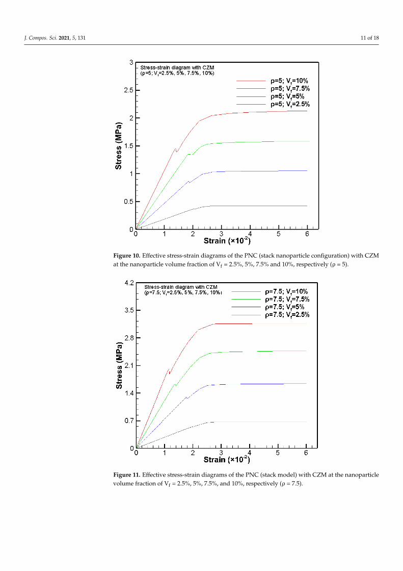
Figures 10–13 show the reduced effective stress-strain diagrams of the PNCs withvarying clay nanoparticle volume fractions (Vf = 2.5, 5, 7.5, and 10) and nanoparticleaspect ratios (ρ = 5, 7.5, 10 and 20) by FEA integrated with CZM based on the stack claynanoparticle configuration. In each effective stress-strain diagram, there is a numericallyfictitious stress drop in the linearly loading range due to debonding initiation-inducedmaterial softening. Such stress dropping phenomenon is decaying with decreasing Vf,and nearly no stress dropping is observable at Vf = 2.5%. For the purpose of comparison,Figure 14 also shows the effective stress-strain diagrams for ρ = 5 and Vf = 2.5, 5, 7.5,and 10 by FEA integrated with CZM based on the stagger clay nanoparticle configuration(Figure 6). It can be found from Figures 10 and 14 that the simulations based on the staggerclay nanoparticle configuration demonstrate no stress dropping and slightly large effectivetensile strength. Such observation is due to the fact that the stagger clay nanoparticleconfiguration designates more evenly distributed clay nanoparticles in the polymericmatrix, corresponding to a higher load-carrying capacity, i.e., a higher effective tensilestrength of the PNC [9,10]. In addition, the more evenly distributed stress state in the RVEwith a stagger clay nanoparticle configuration suppresses the unable debonding of thenanoparticles, and thus no obvious stress dropping is observed in Figure 14.
Figures 15–18 show the reduced effective stress-strain diagrams of the PNCs withvarying clay nanoparticle volume fractions (Vf = 2.5, 5, 7.5, and 10) and aspect ratios (ρ = 5,7.5, 10 and 20) by FEA without CZM based on the stack clay nanoparticle configuration.In this case, the numerical simulations are purely conventional nonlinear FEA withouttaking into account debonding induced failure. Once the polymeric resin reaches its yieldstrength, the PNC reaches its effective ultimate tensile strength, i.e., the yielding of thepolymeric resin governs the effective ultimate tensile strength of the PNC [9,10]. Therefore,the shapes of the effective stress-strain diagrams are close to those of idealized elastoplasticmaterials. For the purpose of comparison, Figure 19 also shows the effective stress-straindiagrams of the PNCs at ρ = 5 and Vf = 2.5, 5, 7.5, and 10 by FEA without CZM based on thestagger clay nanoparticle configuration. It can be found from Figures 15 and 19 that the twocases of nanoparticle distribution configurations predict very close results though the stackclay nanoparticle configuration demonstrates a slightly higher stress state due to its lesssymmetric configuration compared to that of the stagger clay nanoparticle configuration.
J. Compos. Sci. 2021, 5, 131 11 of 18
J. Compos. Sci. 2021, 5, x FOR PEER REVIEW 11 of 19
stagger clay nanoparticle configuration demonstrate no stress dropping and slightly
large effective tensile strength. Such observation is due to the fact that the stagger clay
nanoparticle configuration designates more evenly distributed clay nanoparticles in the
polymeric matrix, corresponding to a higher load-carrying capacity, i.e., a higher effec-
tive tensile strength of the PNC [9,10]. In addition, the more evenly distributed stress
state in the RVE with a stagger clay nanoparticle configuration suppresses the unable
debonding of the nanoparticles, and thus no obvious stress dropping is observed in Fig-
ure 14.
Figure 10. Effective stress-strain diagrams of the PNC (stack nanoparticle configuration) with CZM
at the nanoparticle volume fraction of Vf = 2.5%, 5%, 7.5% and 10%, respectively (ρ = 5).
Figure 11. Effective stress-strain diagrams of the PNC (stack model) with CZM at the nanoparticle
volume fraction of Vf = 2.5%, 5%, 7.5%, and 10%, respectively (ρ = 7.5).
Figure 10. Effective stress-strain diagrams of the PNC (stack nanoparticle configuration) with CZMat the nanoparticle volume fraction of Vf = 2.5%, 5%, 7.5% and 10%, respectively (ρ = 5).
Figure 11. Effective stress-strain diagrams of the PNC (stack model) with CZM at the nanoparticlevolume fraction of Vf = 2.5%, 5%, 7.5%, and 10%, respectively (ρ = 7.5).

J. Compos. Sci. 2021, 5, 131 12 of 18
Figure 12. Effective stress-strain diagrams of the PNC (stack nanoparticle configuration) with CZMat the nanoparticle volume fraction of Vf = 2.5%, 5%, 7.5%, and 10%, respectively (ρ = 10).
Figure 13. Effective stress-strain diagrams of the PNC (stack nanoparticle configuration) with CZMat the nanoparticle volume fraction of Vf = 2.5%, 5%, 7.5%, and 10%, respectively (ρ = 20).

J. Compos. Sci. 2021, 5, 131 13 of 18
Figure 14. Effective stress-strain diagrams of the PNC (stagger nanoparticle configuration) with CZMat the nanoparticle volume fractions Vf = 2.5%, 5%, 7.5%, and 10% at the clay particle aspect ratioρ = 5.
Figure 15. Effective stress-strain diagrams of the PNC (stack nanoparticle configuration) withoutCZM at the nanoparticle volume fraction of Vf = 2.5%, 5%, 7.5%, and 10%, respectively (ρ = 5).

J. Compos. Sci. 2021, 5, 131 14 of 18
Figure 16. Effective stress-strain diagrams of the PNC (stack nanoparticle configuration) withoutCZM at the nanoparticle volume fraction of Vf = 2.5%, 5%, 7.5%, and 10%, respectively (ρ = 7.5).
Figure 17. Effective stress-strain diagrams of the PNC (stack nanoparticle configuration) withoutCZM at the nanoparticle volume fraction of Vf = 2.5%, 5%, 7.5%, and 10%, respectively (ρ = 10).

J. Compos. Sci. 2021, 5, 131 15 of 18
Figure 18. Effective stress-strain diagrams of the PNC (stack nanoparticle configuration) withoutCZM at the nanoparticle volume fraction of Vf = 2.5%, 5%, 7.5%, and 10%, respectively (ρ = 20).
Figure 19. Effective stress-strain diagrams of the PNC (stagger nanoparticle configuration) withoutCZM at the nanoparticle volume fraction of Vf = 2.5%, 5%, 7.5%, and 10%, respectively (ρ = 5).
Figure 20 shows the typical von Mises stress and displacement fields of the REV inthe progressive debonding process of the edge-curved clay nanoparticle under uniaxialtensile loading along the clay nanoparticle direction by using FEA integrated with CZM, inwhich the stack clay nanoparticle configuration is evoked. Compared to Figure 7 basedon a rectangle-shaped clay nanoparticle, the peak von Mises stress decreases ~12% due to

J. Compos. Sci. 2021, 5, 131 16 of 18
adoption of the curved edges. Such a stress decrease is obvious as the result of eliminatingthe stress singularity in the RVE reinforced with edge-curved clay nanoparticles.
Figure 20. von Mises stress and displacement fields of the RVE of a PNC reinforced with an edge-curved clay nanoparticle:(a) crack initiates, (b) crack propagates, and (c) crack propagates to the final failure.
Figures 21 and 22 show the effective stress-strain diagrams of the PNCs of ρ = 5 andVf = 2.5, 5, 7.5, and 10 by FEA integrated with and without CZM, respectively, based onthe stack edge-curved clay nanoparticle configuration. It can be found from Figure 21that obvious stress dropping exists in the effective stress-strain diagrams for the simu-lations by FEA integrated with CZM, while no obvious stress dropping is detected forthose simulations by using FEA without integration of CZM (Figure 22). In addition, thestress level predicted by FEA integrated with CZM (Figure 21) is larger than that withoutintegration of CZM (Figure 22). In this case, debonding predicted by FEA integrated withCZM (Figure 21) induces a larger stress level at the crack tip than that at the same locationof perfectly bonded edge-curved clay nanoparticle in the polymeric resin (Figure 22).
Figure 21. Effective stress-strain diagrams of the PNC (reinforced with edge-curved clay nanoparti-cles) with CZM at the nanoparticle volume fraction of Vf = 2.5%, 5%, 7.5%, and 10%, respectively(ρ = 5).

J. Compos. Sci. 2021, 5, 131 17 of 18
Figure 22. Effective stress-strain diagrams of the PNC (reinforced with edge-curved clay nanoparti-cles) without CZM at the nanoparticle volume fraction of Vf = 2.5%, 5%, 7.5%, and 10%, respectively(ρ = 5).
4. Conclusions
The cohesive zone model (CZM) has been integrated into FEM to successfully sim-ulate the entire effective uniaxial stress-strain diagrams of PNCs in a large range of claynanoparticle volume fraction and aspect ratio. During the numerical process of each case ofthe clay nanoparticle volume fraction and aspect ratio, two configurations of aligned claynanoparticle distribution, i.e., the stack and stagger nanoparticle configurations, have beentaken into account to approach two idealized clay particle distribution states. Detailedeffective uniaxial stress-strain diagrams of the PNCs have been obtained and comparedto successfully explore the effects of PNC processing parameters (i.e., the nanoclay vol-ume fraction, aspect ratio, and alignment). It has been shown that increasing either claynanoparticle volume fraction, aspect ratio, or alignment is the feasible technical approachto achieve high load-carrying capacity, including the effective stiffness and strength of thePNCs. The present CZM-based FEA is capable of predicting the progressive debondingprocess of the clay nanoparticles in polymer resins under uniaxial tension, which is closerto the realistic failure process of PNCs. Therefore, the present CZM-based FEA can be usedto design and optimize the mechanical properties of PNCs. Moreover, the present com-putational approach can be furthered to include additional material and microstructuralproperties of PNCs, e.g., nanosized clay-resin interface features, clay particle waviness,three-dimensional geometries, etc. The present CZM-based FEA provides a feasible whileeffective computational tool for the efficient computer-aided nanocomposite design fortargeted mechanical and physical properties and manufacturing.
Author Contributions: X.-F.W. conceived and designed the computational study; U.C. conducted allthe FEM simulations and figure plotting; U.C. and X.-F.W. analyzed the data and wrote the paper.All authors have read and agreed to the published version of the manuscript.
Funding: This research was supported by the NASA EPSCoR (NASA grant #NNX07AK81A, seedgrant: 43500-2490-FAR018640), NDSU Development Foundation (grant no.: 43500-2490-FAR0017475),and the Department of Mechanical Engineering at NDSU.

J. Compos. Sci. 2021, 5, 131 18 of 18
Conflicts of Interest: The authors declare no conflict of interest.
References1. Dzenis, A. Structural nanocomposites. Science 1998, 319, 419–420. [CrossRef]2. Wu, X.F.; Yarin, A.L. Recent progress in interfacial toughening and damage self-healing of polymer composites based on
electrospun and solution-blown nanofibers. J. Appl. Polym. Sci. 2013, 130, 2225–2237. [CrossRef]3. Chen, Q.; Zhang, L.; Yoon, M.K.; Wu, X.F.; Arefin, R.H.; Fong, H. Preparation and evaluation of nano-epoxy composite resins
containing electrospun glass nanofibers. J. Appl. Polym. Sci. 2012, 124, 444–451. [CrossRef]4. Wu, X.F.; Rahman, A.; Zhou, Z.; Pelot, D.D.; Sinha-Ray, S.; Chen, B.; Payne, S.; Yarin, A.L. Electrospinning core-shell nanofibers
for interfacial toughening and self-healing of carbon-fiber/epoxy composites. J. Appl. Polym. Sci. 2013, 129, 1383–1393. [CrossRef]5. Wu, X.F.; Zholobko, O.; Zhou, Z.; Rahman, A. Electrospun nanofibers for interfacial toughening and damage self-healing of
polymer composites and surface coatings. In Electrospun Polymers and Composites: Ultrafine Materials, High Performance Fibers andWearables; Woodhead Publishing: Oxford, UK, 2020.
6. Usuki, A.; Kojima, Y.; Kawasumi, M.; Okada, A.; Fukushima, Y.; Kurauchi, T.; Kamigaito, O. Synthesis of nylon 6-clay hybrid.J. Mater. Res. 1993, 8, 1179–1184. [CrossRef]
7. Chan, M.; Lau, K.; Wong, T.; Ho, M.; Hui, D. Mechanism of reinforcement in a nanoclay/polymer composite. Composites B Eng.2011, 42, 1708–1712. [CrossRef]
8. Almansoori, A.; Majewski, C.; Rodenburg, C. Nanoclay/polymer composite powders for use in laser sintering applications:Effects of nanoclay plasma treatment. J. Mater. 2017, 69, 2278–2285. [CrossRef] [PubMed]
9. Rahman, A.; Wu, X.F. Computational study of the effects of processing parameters on the nonlinear elastoplastic behavior ofpolymer nanoclay composites. J. Compos. Sci. 2017, 1, 16. [CrossRef]
10. Rahman, A. Fabrication and Mechanical Characterization of Novel Hybrid Carbon-fiber/Epoxy Composites Reinforced withToughening/Self-Repairing Nanofibers at Interfaces. Ph.D. Thesis, North Dakota State University, Fargo, ND, USA, 2012.
11. Kojima, Y.; Usuki, A.; Kawasumi, M.; Okada, A.; Kurauchi, T.; Kamigaito, O. Synthesis of nylon 6–clay hybrid by montmorilloniteintercalated with ε-caprolactam. J. Polym. Sci. A Polym. Chem. 1993, 31, 983–986. [CrossRef]
12. Alexandre, M.; Dubois, P. Polymer-layered silicate nanocomposites: Preparation, properties and uses of a new class of materials.Mater. Sci. Eng. R Rep. 2000, 28, 1–63. [CrossRef]
13. Chen, Y.; Chen, H.; Shi, J. In vivo bio-safety evaluations and diagnostic/therapeutic applications of chemically designedmesoporous silica nanoparticles. Adv. Mater. 2013, 25, 3144–3176. [CrossRef]
14. Tjong, S.C. Structural and mechanical properties of polymer nanocomposites. Mater. Sci. Eng. R Rep. 2006, 53, 73–197. [CrossRef]15. Schadler, L.; Brinson, L.; Sawyer, W. Polymer nanocomposites: A small part of the story. J. Mater. 2007, 59, 53–60. [CrossRef]16. Paul, D.R.; Robeson, L.M. Polymer nanotechnology: Nanocomposites. Polymer 2008, 49, 3187–3204. [CrossRef]17. Tucker, C.L., III.; Liang, E. Stiffness predictions for unidirectional short-fiber composites: Review and evaluation. Compos. Sci.
Technol. 1999, 59, 655–671. [CrossRef]18. Weon, J.I.; Sue, H.J. Effects of clay orientation and aspect ratio on mechanical behavior of nylon-6 nanocomposite. Polymer 2005,
46, 6325–6334. [CrossRef]19. Tsai, J.; Sun, C. Effect of platelet dispersion on the load transfer efficiency in nanoclay composites. J. Compos. Mater. 2004, 38,
567–579. [CrossRef]20. Dong, Y.; Bhattacharyya, D. A simple micromechanical approach to predict mechanical behaviour of polypropylene/organoclay
nanocomposites based on representative volume element (RVE). Comput. Mater. Sci. 2010, 49, 1–8. [CrossRef]21. Hu, H.; Onyebueke, L.; Abatan, A. Characterizing and modeling mechanical properties of nanocomposites-review and evaluation.
J. Miner. Mater. Character. Eng. 2010, 9, 275–319. [CrossRef]22. Barenblatt, G.I. The formation of equilibrium cracks during brittle fracture: General ideas and hypotheses, axially symmetric
cracks. Appl. Math. Mech. 1959, 23, 622–636. [CrossRef]23. Barenblatt, G.I. The mathematical theory of equilibrium in brittle fracture. Adv. Appl. Mech. 1962, 7, 55–129.24. Dugdale, D.S. Yielding of steel sheets containing slits. J. Mech. Phys. Solids 1960, 8, 100–104. [CrossRef]25. Park, K.; Paulino, G.H. Cohesive zone models: A critical review of traction-separation relationships across fracture surfaces. Appl.
Mech. Rev. 2011, 64, 060802. [CrossRef]26. ANSYS®Theory Reference (Version 16); ANSYS, Inc.: Canonsburg, PA, USA, 2016.27. Wu, X.F.; Chowdhury, U. Computational analysis of the mechanical strength and debonding process of adhesively bonded joints.
Int. J. Solid Mater. 2019, 1, 171–225.28. Chowdhury, U. Theoretical and Computational Studies of the Strength and Fracture Toughness of Adhesively Bonded Joints and
Polymer Nanoclay Composites. Ph.D. Thesis, North Dakota State University, Fargo, ND, USA, 2018.