cigre us national committee 2015 grid of the future symposium
TRANSCRIPT
Synchronous Machine-Based Multi-Converter System With Online Interaction Monitoring Function
I. CVETKOVIC1, D. BOROYEVICH
1, R. BURGOS
1, C. LI
1, P. MATTAVELLI
2
1 Center for Power Electronics Systems (CPES)
Virginia Tech, Blacksburg, VA 24061
USA
2 Department of Management and
Engineering, University of Padova
Italy
SUMMARY
The advancement of power electronics has been a key enabler of the vast proliferation of renewable
energy sources in the electrical power grid over the past several years, acting both as energy source
interface and as compensation asset in HVDC and FACTS-supported ac systems for energy transport.
This trend, together with the ever-increasing deployment of electronically-interfaced loads, as well as
the increasing penetration of microgrids, is fundamentally changing the nature of the sources and the
loads in the electrical grid, altering their conventionally mild aggregate dynamics, and inflicting low-
and high- frequency dynamic interactions that existed never before. Consequently, high dispersion of
power electronics into the future grid will highly depend on engineers’ capability to understand,
model, and dynamically control power sharing and subsystem interactions.
With the recent revision of the IEEE 1547 standard that now for the first time allows distributed
generation to regulate voltage at the point of common coupling, numerous research groups have
started exploring unconventional ways to control grid-interface converters. Such change
incontrovertibly requires new concepts for advanced control of all energy flows in order to improve
system stability, energy availability, and reliability. This paper presents a grid-interface converter that
behaves as a synchronous machine, and shows how its adaptive virtual inertia can mitigate system
instability caused by partial loss of generation. Additionally, it shows one of the ways to implement an
online stability monitoring function by observing small-signal active and reactive power at converter
terminals.
KEYWORDS
Grid-interface converters, grid stability, microgrid stability, dynamic interactions, converter
modelling, converter control, online stability monitoring;
21, rue d’Artois, F-75008 PARIS CIGRE US National Committee
http : //www.cigre.org 2015 Grid of the Future Symposium
1
INTRODUCTION
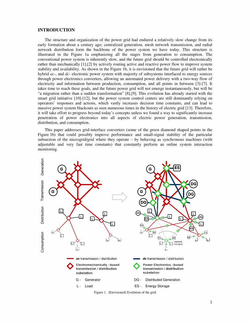
The structure and organization of the power grid had endured a relatively slow change from its
early formation about a century ago; centralized generation, mesh network transmission, and radial
network distribution form the backbone of the power system we have today. This structure is
illustrated in the Figure 1a emphasizing all the stages from generation to consumption. The
conventional power system is inherently slow, and the future grid should be controlled electronically
rather than mechanically [1],[2] by actively routing active and reactive power flow to improve system
stability and availability. As shown in the Figure 1b, it is envisioned that the future grid will rather be
hybrid ac-, and dc- electronic power system with majority of subsystems interfaced to energy sources
through power electronics converters, allowing an automated power delivery with a two-way flow of
electricity and information between production, consumption, and all points in between [3]-[7]. It
takes time to reach these goals, and the future power grid will not emerge instantaneously, but will be
“a migration rather than a sudden transformation” [8],[9]. This evolution has already started with the
smart grid initiative [10]-[12], but the power system control centers are still dominantly relying on
operators’ responses and actions, which vastly increases decision time constants, and can lead to
massive power system blackouts as seen numerous times in the history of electric grid [13]. Therefore,
it will take effort to progress beyond today’s concepts unless we found a way to significantly increase
penetration of power electronics into all aspects of electric power generation, transmission,
distribution, and consumption.
This paper addresses grid-interface converters (some of the green diamond shaped points in the
Figure 1b) that could possibly improve performance and small-signal stability of the particular
subsection of the microgrid/grid where they operate – by behaving as synchronous machines (with
adjustable and very fast time constants) that constantly perform an online system interaction
monitoring.
G - Generator DG - Distributed Generation
L - Load ES - Energy Storage
Figure 1. (Envisioned) Evolution of the grid
2
SYNCHROUS MACHINE-BASED GRID-INTERFACE CONVERTERS
Due to physical limitations, construction, and materials necessary for electromechanical power
conversion process, synchronous machines intrinsically feature very long time constants that often
negatively impact small-signal stability. On the other hand, integration of distributed energy resources
requires power sharing and synchronization, and the current approach is to operate the grid-interface
converters as current sources for maximum primary-source power tracking, and to achieve the
synchronization through low-bandwidth phase-locked loops. These power converters demonstrate
negative incremental output resistance which makes them susceptible to the low-frequency dynamic
interactions with other sources and loads on the grid that are trying to synchronize at the same time.
Additionally, as the load power converters make the final load more robust to the variations in the grid
voltage, they also present a negative incremental input resistance which may initiate low-frequency
dynamic interactions. Fortunately, recent revision of the IEEE 1547 standard now for the first time
allows distributed generation to regulate voltage at the point of common coupling, and that steered
various research groups to start exploring unconventional ways to control grid-interface converters in
order to overcome above listed problems. One such way is controlling power converters to behave as
synchronous machines, taking advantage of the inherent self-synchronization property, virtual inertia,
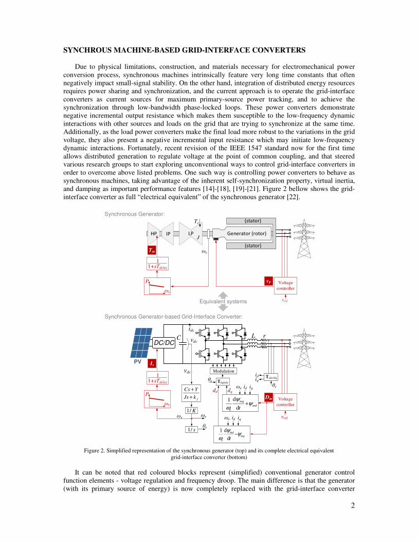
and damping as important performance features [14]-[18], [19]-[21]. Figure 2 bellow shows the grid-
interface converter as full “electrical equivalent” of the synchronous generator [22].
C vdc
L r
Tdq/abc
Modulation
dd dq
mqmd
e tψ
ψ
ω−
d
d1
md
mq
e tψ
ψ
ω+
d
d1
θe
idiq
Tabc/dqθe
id iqωe
DC/DC
Voltage
controller
vref
vdc
s/1
K/1
fkJs
YCs
+
+
ωe
P
1+sTdelay
1
Generator (rotor)HP IP
Voltage
controller
vref
ωe
P
1+sTdelay
1
LPJ
ωe
(stator)
(stator)Tm
vF
Is
Dm
Synchronous Generator:
Synchronous Generator-based Grid-Interface Converter:
PV
idc
Equivalent systems
Te
ωeωe
θe
id iqωe
Figure 2. Simplified representation of the synchronous generator (top) and its complete electrical equivalent
grid-interface converter (bottom)
It can be noted that red coloured blocks represent (simplified) conventional generator control
function elements - voltage regulation and frequency droop. The main difference is that the generator
(with its primary source of energy) is now completely replaced with the grid-interface converter
3
(primary source here chosen arbitrarily to be the photovoltaic farm, but can be any other renewable or
distributed energy resource). Mechanical torque Tm of the generator primary source is completely dual
to the input current Is of the grid-interface converter (this is also physically adequate due to the fact
that torque in mechanical systems is equivalent to current in electrical systems), and controls active
power flow in synchronous generators, while excitation voltage vF is dual to the modulation index of
power converter (the value of Dm varies from 0 to 1), therefore, as in synchronous machines, it only
has effects on the terminal voltage (and reactive power), with negligible effects on the active power
flow.
The structure shown above in Figure 2 (bottom – black colored blocks only), is completely dual to
any type of synchronous machine (salient pole or round rotor) with field, and any number of damper
windings. Mathematical derivations and fully equivalent average model are described in details in
[23]. Self-synchronization and concept of virtual inertia will be briefly summarized here for
completeness.
Self-Synchronisation of Grid-Interface Converters
Synchronous generators when connected to the grid follow changes in the grid’s angular
frequency with the zero steady-state error. This is not only due to the precise speed regulation of the
turbines, but rather due to an inherent synchronization property of the synchronous machines, as it is
well-known.
The machine rotor dynamics can be described with (1) and (2), where electrical angular frequency
ωe is mechanical times machine pair of poles (Ωmp); kf is a friction coefficient, and Tm and Te are
respectively mechanical and electrical torque.
mfem
m kTTt
J Ω−−=Ω
d
d
(1)
oeee
ee
m twheretp
θωθωθω
∫ +==⇒=Ω dd
d
(2)
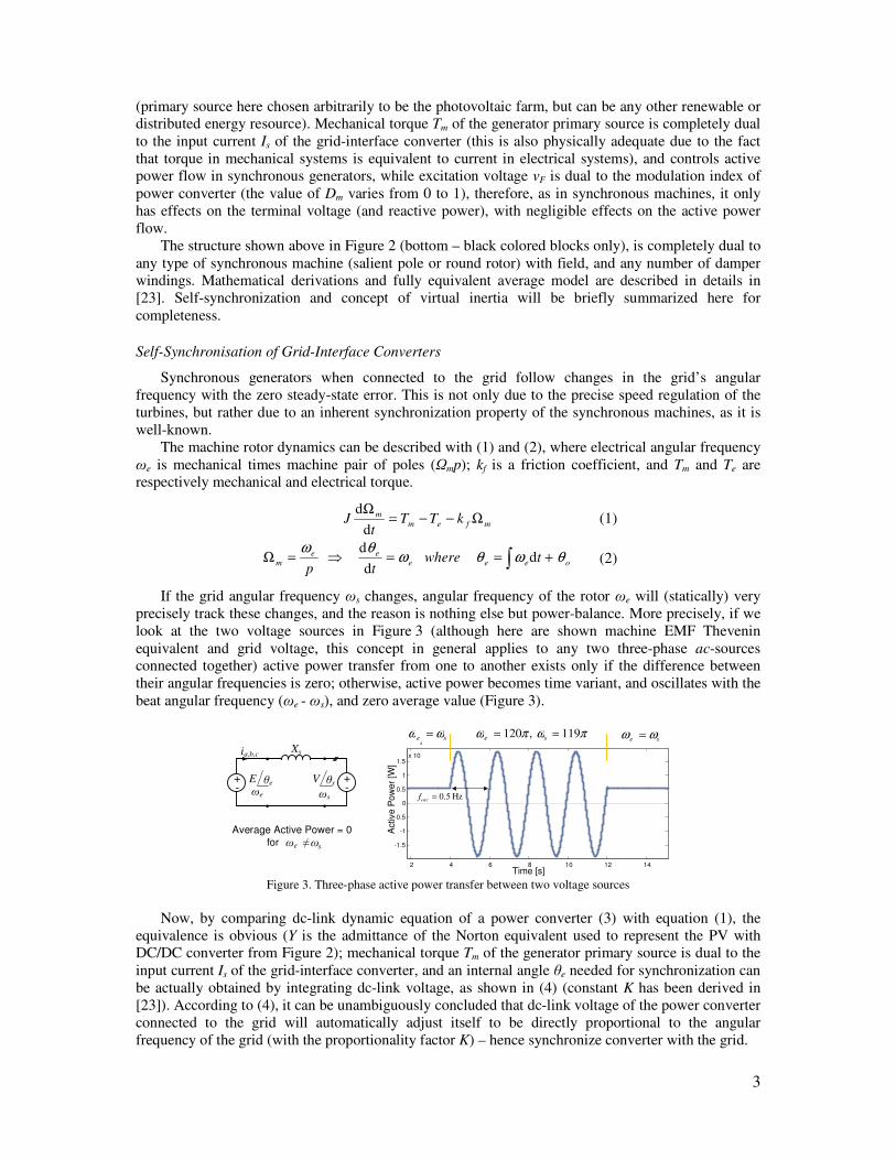
If the grid angular frequency ωs changes, angular frequency of the rotor ωe will (statically) very
precisely track these changes, and the reason is nothing else but power-balance. More precisely, if we
look at the two voltage sources in Figure 3 (although here are shown machine EMF Thevenin
equivalent and grid voltage, this concept in general applies to any two three-phase ac-sources
connected together) active power transfer from one to another exists only if the difference between
their angular frequencies is zero; otherwise, active power becomes time variant, and oscillates with the
beat angular frequency (ωe - ωs), and zero average value (Figure 3).
Xsia,b,c
+-
E+-
Average Active Power = 0
for ωe ≠ ωs
2 4 6 8 10 12 14
-1.5
-1
-0.5
0
0.5
1
1.5x 10
4
Time [s]
Act
ive P
ow
er
[W]
se ωω = πωπω 119,120 == se se ωω =
Hz5.0=oscf
θe V θs
ωe ωs
Figure 3. Three-phase active power transfer between two voltage sources
Now, by comparing dc-link dynamic equation of a power converter (3) with equation (1), the
equivalence is obvious (Y is the admittance of the Norton equivalent used to represent the PV with
DC/DC converter from Figure 2); mechanical torque Tm of the generator primary source is dual to the
input current Is of the grid-interface converter, and an internal angle θe needed for synchronization can
be actually obtained by integrating dc-link voltage, as shown in (4) (constant K has been derived in
[23]). According to (4), it can be unambiguously concluded that dc-link voltage of the power converter
connected to the grid will automatically adjust itself to be directly proportional to the angular
frequency of the grid (with the proportionality factor K) – hence synchronize converter with the grid.
4
dc
dc
d
dYvII
t
vC dcs −−=
(3)
o
dc
ee
e
edc tK
vwhere
tKv θθω
θω ∫ +==⇒≡ d
d
d
(4)
This shows that grid-interface converters that behave as synchronous machines do not need
additional phase-, or frequency-locked loop to synchronize to the grid. It is, in fact, sufficient to
integrate dc-link voltage in order to obtain synchronization angle. This angle (θe) will now be used to
define (and generate) d-q coordinate system of the grid-interface converter (as it is a common practice
in machine analysis).
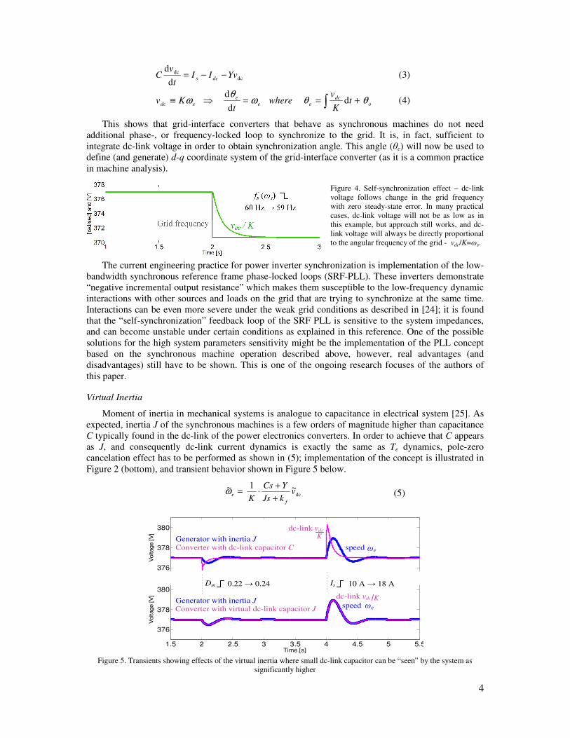
Figure 4. Self-synchronization effect – dc-link
voltage follows change in the grid frequency
with zero steady-state error. In many practical
cases, dc-link voltage will not be as low as in
this example, but approach still works, and dc-
link voltage will always be directly proportional
to the angular frequency of the grid - vdc/K=ωs.
The current engineering practice for power inverter synchronization is implementation of the low-
bandwidth synchronous reference frame phase-locked loops (SRF-PLL). These inverters demonstrate
“negative incremental output resistance” which makes them susceptible to the low-frequency dynamic
interactions with other sources and loads on the grid that are trying to synchronize at the same time.
Interactions can be even more severe under the weak grid conditions as described in [24]; it is found
that the “self-synchronization” feedback loop of the SRF PLL is sensitive to the system impedances,
and can become unstable under certain conditions as explained in this reference. One of the possible
solutions for the high system parameters sensitivity might be the implementation of the PLL concept
based on the synchronous machine operation described above, however, real advantages (and
disadvantages) still have to be shown. This is one of the ongoing research focuses of the authors of
this paper.
Virtual Inertia
Moment of inertia in mechanical systems is analogue to capacitance in electrical system [25]. As
expected, inertia J of the synchronous machines is a few orders of magnitude higher than capacitance
C typically found in the dc-link of the power electronics converters. In order to achieve that C appears
as J, and consequently dc-link current dynamics is exactly the same as Te dynamics, pole-zero
cancelation effect has to be performed as shown in (5); implementation of the concept is illustrated in
Figure 2 (bottom), and transient behavior shown in Figure 5 below.
dc~1~ v
kJs
YCs
K f
e+
+⋅=ω (5)
1.5 2 2.5 3 3.5 4 4.5 5 5.5
376
378
380
Time [s]
Voltage [V
]
1.5 2 2.5 3 3.5 4 4.5 5 5.5
376
378
380
Time [s]
Voltage [V
]
Generator with inertia JConverter with dc-link capacitor C speed ωm
dc-link vdc
Generator with inertia JConverter with virtual dc-link capacitor J
speed ωm
dc-link vdc
Dm Is0.22 → 0.24 10 A → 18 A
K
K
ωe
ωe
Figure 5. Transients showing effects of the virtual inertia where small dc-link capacitor can be “seen” by the system as
significantly higher
5
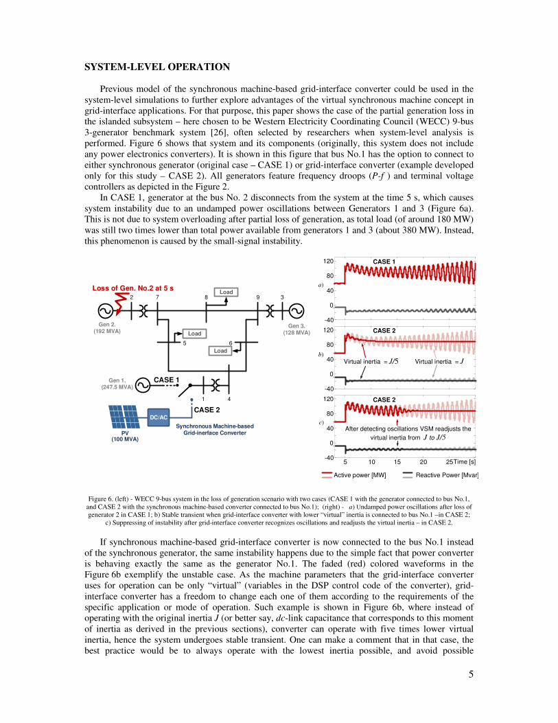
SYSTEM-LEVEL OPERATION
Previous model of the synchronous machine-based grid-interface converter could be used in the
system-level simulations to further explore advantages of the virtual synchronous machine concept in
grid-interface applications. For that purpose, this paper shows the case of the partial generation loss in
the islanded subsystem – here chosen to be Western Electricity Coordinating Council (WECC) 9-bus
3-generator benchmark system [26], often selected by researchers when system-level analysis is
performed. Figure 6 shows that system and its components (originally, this system does not include
any power electronics converters). It is shown in this figure that bus No.1 has the option to connect to
either synchronous generator (original case – CASE 1) or grid-interface converter (example developed
only for this study – CASE 2). All generators feature frequency droops (P-f ) and terminal voltage
controllers as depicted in the Figure 2.
In CASE 1, generator at the bus No. 2 disconnects from the system at the time 5 s, which causes
system instability due to an undamped power oscillations between Generators 1 and 3 (Figure 6a).
This is not due to system overloading after partial loss of generation, as total load (of around 180 MW)
was still two times lower than total power available from generators 1 and 3 (about 380 MW). Instead,
this phenomenon is caused by the small-signal instability.
PV
Synchronous Machine-basedGrid-inerface Converter
DC/AC
Gen 1.(247.5 MVA)
Gen 2.(192 MVA)
Gen 3.(128 MVA)
2 7 8 9 3
5 6
1 4
Load
Load
Load
(100 MVA)
Loss of Gen. No.2 at 5 s
CASE 1
CASE 2
-40
0
40
80
120
5 10 15 20 25-40
0
40
80
120
Virtual inertia = J/5 Virtual inertia = J
After detecting oscillations VSM readjusts the
virtual inertia from J to J/5
Active power [MW] Reactive Power [Mvar]
Time [s]
b)
c)
-40
0
40
80
120
a)
CASE 1
CASE 2
CASE 2
Figure 6. (left) - WECC 9-bus system in the loss of generation scenario with two cases (CASE 1 with the generator connected to bus No.1,
and CASE 2 with the synchronous machine-based converter connected to bus No.1); (right) - a) Undamped power oscillations after loss of
generator 2 in CASE 1; b) Stable transient when grid-interface converter with lower “virtual” inertia is connected to bus No.1 –in CASE 2;
c) Suppressing of instability after grid-interface converter recognizes oscillations and readjusts the virtual inertia – in CASE 2.
If synchronous machine-based grid-interface converter is now connected to the bus No.1 instead
of the synchronous generator, the same instability happens due to the simple fact that power converter
is behaving exactly the same as the generator No.1. The faded (red) colored waveforms in the
Figure 6b exemplify the unstable case. As the machine parameters that the grid-interface converter
uses for operation can be only “virtual” (variables in the DSP control code of the converter), grid-
interface converter has a freedom to change each one of them according to the requirements of the
specific application or mode of operation. Such example is shown in Figure 6b, where instead of
operating with the original inertia J (or better say, dc-link capacitance that corresponds to this moment
of inertia as derived in the previous sections), converter can operate with five times lower virtual
inertia, hence the system undergoes stable transient. One can make a comment that in that case, the
best practice would be to always operate with the lowest inertia possible, and avoid possible
6
oscillations in the system; however, as shown in [27], low overall inertia is not always the best
approach to increase system stability margin. Instead, this should be achieved in an adaptive manner,
by recognizing operating irregularities in the real-time, and acting accordingly to mitigate them. Such
example is shown in Figure 6c, where grid-interface converter recognizes undamped system
oscillations, and adaptively readjusts virtual inertia in order to make an effort to suppress them (in this
particular example, such action is made 10 second after loss of generator 2).
ONLINE INTERACTION MONITORING
One known way to address system interactions is through small-signal stability assessment
[28], [29]. At any ac-interface point stability margins can be determined using Generalized Nyquist
stability Criterion (GNC), calculating loci of the eigenvalues of return ratio L(s) as specified in (6),
while at any dc-interface point that simplifies to (7). In both instances, the concept requires measuring
source-output and load-input impedances at the desired interface point (two-by-two matrices ZS and
ZL=1/YL in ac- case, and single impedances ZS and ZL=1/YL in dc- case). For a stable system, (6) and
(7) must not encircle -1 [29].
( ) ))()(()()(
)(sss
se
se
q
dLS YZeigLeig ⋅==
(6)
)()()( sYsZsL LS ⋅= (7)
Such concept requires an impedance measurement unit [30] to be placed at the desired interface
point and characterize system in situ – measure system output and input impedances. The method has
been shown to be very effective, but less convenient when measuring higher-power/voltage systems,
mainly due to the size and weight of the impedance measurement unit.
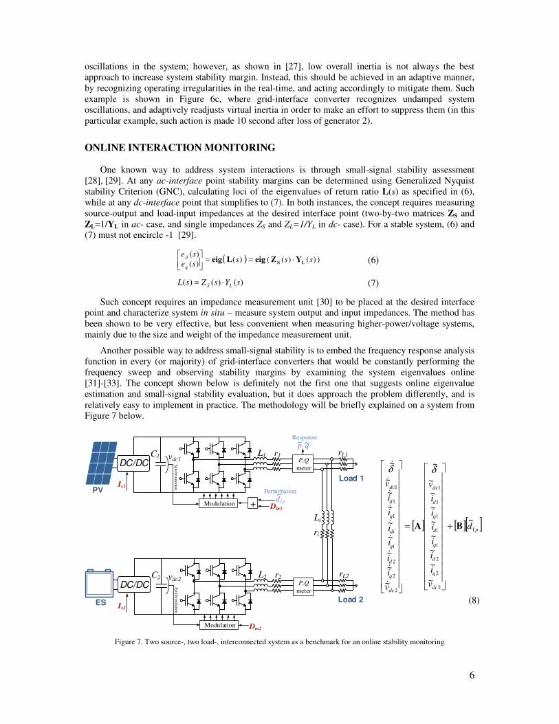
Another possible way to address small-signal stability is to embed the frequency response analysis
function in every (or majority) of grid-interface converters that would be constantly performing the
frequency sweep and observing stability margins by examining the system eigenvalues online
[31]-[33]. The concept shown below is definitely not the first one that suggests online eigenvalue
estimation and small-signal stability evaluation, but it does approach the problem differently, and is
relatively easy to implement in practice. The methodology will be briefly explained on a system from
Figure 7 below.
C1
Is1
vdc1L1 r1
Modulation
DC/DC
Li
ri
C2
Is2
vdc2L2 r2
Modulation
DC/DC
PV
ES
Dm1+
Dm2
rL1
rL2
P,Q
meter
P,Q
meter
Sy
nc
hro
niza
tion
Sy
nc
hro
niza
tion
Perturbation
Response
Load 1
Load 2
d1p
p q
[ ] [ ][ ]p
dc
q
d
qi
di
q
d
dc
dc
q
d
qi
di
q
d
dc
d
v
i
i
i
i
i
i
v
v
i
i
i
i
i
i
v
1
2
2
2
1
1
1
2
2
2
1
1
1
~
~
~
~
~
~
~
~
~
~
~
~
~
~
~
~
~
~
~
BA +
=
δδ
&
&
&
&
&
&
&
&
&
(8)
Figure 7. Two source-, two load-, interconnected system as a benchmark for an online stability monitoring
7
Figure 7 illustrates a part of the microgrid that consists of two grid-interface converters interconnected via three-phase line and featuring shunt resistive loads on both ends. One converter
feature the photovoltaic (PV) as a primary energy source, while the other features energy source (ES)
– the choice of the primary sources has been arbitrary, as it does not impact the methodology in any sense. Although the concept is generic and implementable on any type of converters (and converter
controls), it is here performed on converters that behave as synchronous machines.
For simplicity, it can be assumed that both converters operate at the particular operating point with
fixed values of modulation indexes (Dm1 and Dm2). It is well known that in balanced and symmetrical
three-phase systems instantaneous active and reactive power have constant dc values (are time
invariant), and that offers an opportunity to obtain small-signal transfer functions from modulation index to active and reactive power around a desirable operating point.
Instantaneous active and reactive power are (assuming power invariant d-q transformation):
qqddccbbaa ivivivivivp +=++= (9)
qddq
ba
ba
ac
ac
cb
cbiviv
ii
vv
ii
vv
ii
vvq −=++=
222
(10)
With small-signal expressions:
qqqqdddd IviVIviVp ~~~~~ +++= (11)
qdqddqdq IviVIviVq ~~~~~ −−+= (12)
If power converter 1 starts perturbing its modulation index as shown in the Figure 7, the following
two transfer functions can be obtained:
)(
)(~
~and
)(
)(~
~
11sden
snum
d
q
sden
snum
d
p q
p
p
p
==
(13)
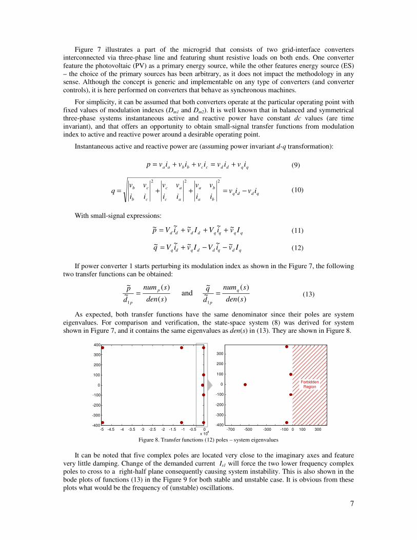
As expected, both transfer functions have the same denominator since their poles are system
eigenvalues. For comparison and verification, the state-space system (8) was derived for system shown in Figure 7, and it contains the same eigenvalues as den(s) in (13). They are shown in Figure 8.
-5 -4.5 -4 -3.5 -3 -2.5 -2 -1.5 -1 -0.5 0x 10
4
-400
-300
-200
-100
0
100
200
300
400
-700 -500 -300 -100 0 100 300-400
-300
-200
-100
0
100
200
300
Forbidden Region
Figure 8. Transfer functions (12) poles – system eigenvalues
It can be noted that five complex poles are located very close to the imaginary axes and feature
very little damping. Change of the demanded current Is1 will force the two lower frequency complex poles to cross to a right-half plane consequently causing system instability. This is also shown in the
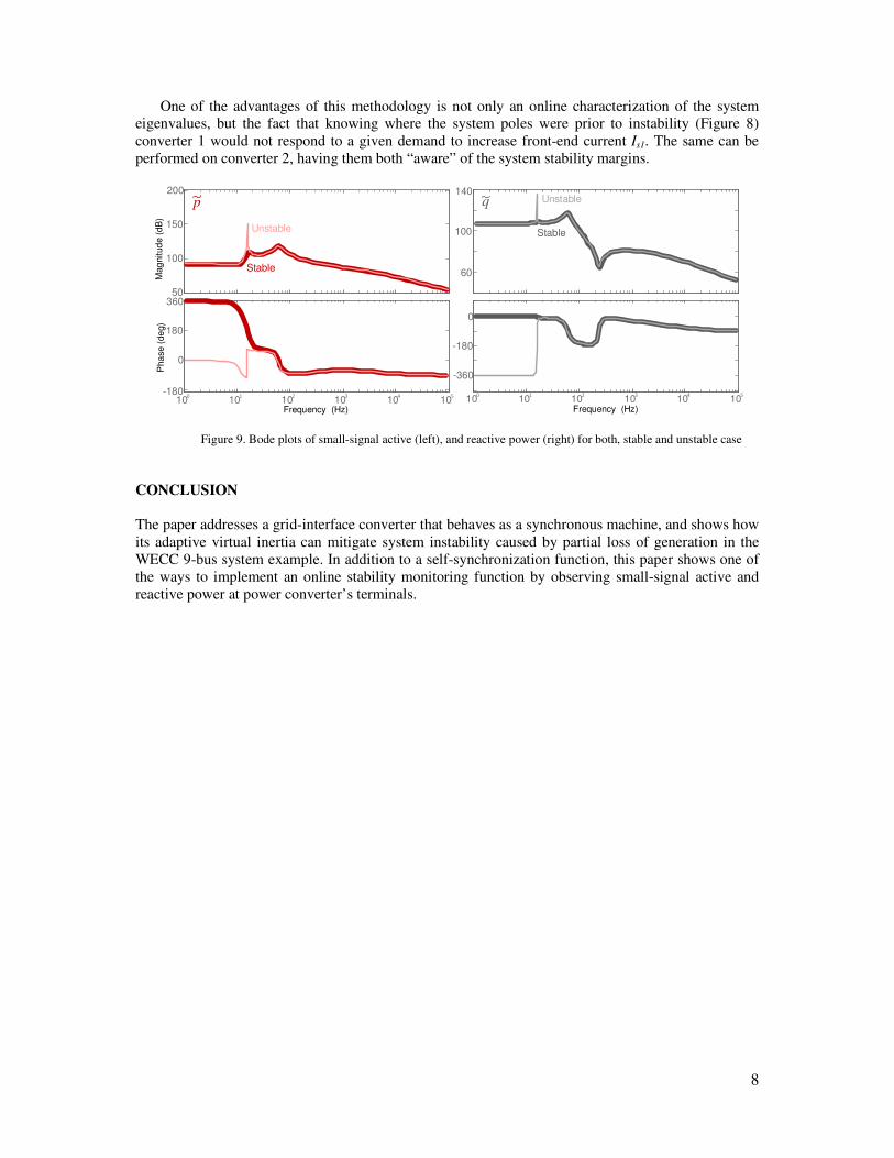
bode plots of functions (13) in the Figure 9 for both stable and unstable case. It is obvious from these
plots what would be the frequency of (unstable) oscillations.
8
One of the advantages of this methodology is not only an online characterization of the system eigenvalues, but the fact that knowing where the system poles were prior to instability (Figure 8)
converter 1 would not respond to a given demand to increase front-end current Is1. The same can be
performed on converter 2, having them both “aware” of the system stability margins.
100
150
200
Mag
nitud
e (
dB
)
100
101
102
103
104
105
-180
0
180
360
Pha
se (
de
g)
Frequency (Hz)
60
100
140
-360
-180
0
Frequency (Hz)
50
100
101
102
103
104
105
Unstable
Stable
Unstable
Stable
p q
Figure 9. Bode plots of small-signal active (left), and reactive power (right) for both, stable and unstable case
CONCLUSION The paper addresses a grid-interface converter that behaves as a synchronous machine, and shows how
its adaptive virtual inertia can mitigate system instability caused by partial loss of generation in the
WECC 9-bus system example. In addition to a self-synchronization function, this paper shows one of
the ways to implement an online stability monitoring function by observing small-signal active and
reactive power at power converter’s terminals.
9
BIBLIOGRAPHY [1] N. G. Hingorani, "Power electronics in electric utilities: role of power electronics in future
power systems", Proceedings of the IEEE, vol. 76, pp. 481-482, 1988.
[2] R. Abe, H. Taoka, and D. McQuilkin, "Digital Grid: Communicative Electrical Grids of the
Future," Smart Grid, IEEE Transactions on, vol. 2, pp. 399-410, 2011.
[3] US Department of Energy: GRID 2030, July 2003. Available: http://www.ferc.gov/eventcalen-
dar/files/20050608125055-grid-2030.pdf.
[4] S. Bifaretti, P. Zanchetta, A. Watson, L. Tarisciotti, and J. C. Clare, "Advanced Power
Electronic Conversion and Control System for Universal and Flexible Power Management," Smart Grid, IEEE Transactions on, vol. 2, pp. 231-243, 2011.
[5] P. Fairley, "Germany jump-starts the supergrid," Spectrum, IEEE, vol. 50, 2013.
[6] P. Juanuwattanakul and M. A. S. Masoum, "Increasing distributed generation penetration in multiphase distribution networks considering grid losses, maximum loading factor and bus
voltage limits," Generation, Transmission & Distribution, IET, vol. 6, pp. 1262-1271, 2012.
[7] S. Xu, A. Q. Huang, S. Lukic, and M. E. Baran, "On Integration of Solid-State Transformer
With Zonal DC Microgrid," Smart Grid, IEEE Transactions on, vol. 3, pp. 975-985, 2012.
[8] M. G. Lauby, "Enabling the power system of the future", in Advances in Power System Control,
Operation and Management (APSCOM 2009), 8th International Conference on, 2009, pp. 1-8.
[9] M. Smith and D. Ton, "Key Connections: The U.S. Department of Energy’s Microgrid
Initiative," Power and Energy Magazine, IEEE, vol. 11, pp. 22-27, 2013.
[10] I. A. Hiskens, "What's smart about the smart grid?", in Design Automation Conference (DAC), 2010 47th ACM/IEEE, 2010, pp. 937-939.
[11] O. HyungSeon, "Optimal Planning to Include Storage Devices in Power Systems," Power
Systems, IEEE Transactions on, vol. 26, pp. 1118-1128, 2011. [12] F. Blaabjerg, A. Consoli, J. A. Ferreira, and J. D. van Wyk, "The future of electronic power
Processing and conversion", Power Electronics, IEEE Transactions on, vol. 20, pp. 715-720,
2005. [13] A. Atputharajah and T. K. Saha, "Power system blackouts - literature review", in Industrial and
Information Systems (ICIIS), 2009 International Conference on, 2009, pp. 460-465.
[14] H. P. Beck and R. Hesse, "Virtual synchronous machine," in Electrical Power Quality and
Utilisation, 2007. EPQU 2007. 9th International Conference on, 2007, pp. 1-6.
[15] Z. Qing-Chang and G. Weiss, "Synchronverters: Inverters That Mimic Synchronous
Generators," Industrial Electronics, IEEE Transactions on, vol. 58, pp. 1259-1267, 2011.
[16] J. Driesen and K. Visscher, "Virtual synchronous generators," in Power and Energy Society
General Meeting - Conversion and Delivery of Electrical Energy in the 21st Century, 2008
IEEE, 2008, pp. 1-3. [17] Z. Lidong, L. Harnefors, and H. P. Nee, "Power-Synchronization Control of Grid-Connected
Voltage-Source Converters," Power Systems, IEEE Transactions on, vol. 25, pp. 809-820, 2010.
[18] M. Torres and L. A. C. Lopes, "Virtual synchronous generator control in autonomous wind-diesel power systems," in Electrical Power & Energy Conference (EPEC), 2009 IEEE, 2009, pp.
1-6.
[19] N. Phi-Long, Z. Qing-Chang, F. Blaabjerg, and J. M. Guerrero, "Synchronverter-based
operation of STATCOM to Mimic Synchronous Condensers," in Industrial Electronics and
Applications (ICIEA), 2012 7th IEEE Conference on, 2012, pp. 942-947.
[20] P. Rodriguez, I. Candela, and A. Luna, "Control of PV generation systems using the
synchronous power controller," in Energy Conversion Congress and Exposition (ECCE), 2013 IEEE, 2013, pp. 993-998.
[21] Z. Qing-Chang, N. Phi-Long, M. Zhenyu, and S. Wanxing, "Self-Synchronized
Synchronverters: Inverters Without a Dedicated Synchronization Unit," Power Electronics, IEEE Transactions on, vol. 29, pp. 617-630, 2014.
[22] I. Cvetkovic, D. Boroyevich, R. Burgos, L. Chi, and P. Mattavelli, " Modeling and Control of
Grid-Connected Voltage-Source Converters Emulating Isotropic and Anisotropic Synchronous
Machines," in Control and Modeling for Power Electronics (COMPEL), 2015 IEEE 15th
Workshop on, 2015.
10
[23] I. Cvetkovic, D. Boroyevich, R. Burgos, L. Chi, M. Jaksic, and P. Mattavelli, "Modeling of a virtual synchronous machine-based grid-interface converter for renewable energy systems
integration," in Control and Modeling for Power Electronics (COMPEL), 2014 IEEE 15th
Workshop on, 2014, pp. 1-7. [24] D. Dong, W. Bo, D. Boroyevich, P. Mattavelli, and X. Yaosuo, "Analysis of Phase-Locked
Loop Low-Frequency Stability in Three-Phase Grid-Connected Power Converters Considering
Impedance Interactions," Industrial Electronics, IEEE Transactions on, vol. 62, pp. 310-321,
2015.
[25] H.F. Olson, Dynamical Analogies, 2nd ed., Van Nostrand, pp. 27–29., 1958.
[26] P. W. Sauer and M. A. Pai. Power System Dynamics and Stability. Prentice-Hall, Upper Saddle River, NJ, 1998.
[27] M. Torres and L. A. C. Lopes, "Virtual synchronous generator control in autonomous wind-
diesel power systems," in Electrical Power & Energy Conference (EPEC), 2009 IEEE, 2009, pp. 1-6.
[28] R. D. Middlebrook, “Input filter considerations in design and application of switching
regulators,” in Proceed. IEEE IAS ’76, pp. 366−382, 1976. [29] M. Belkhayat, “Stability criteria for ac power systems with regulated loads,” PhD dissertation,
Purdue University, 1997.
[30] I. Cvetkovic, Z. Shen, M. Jaksic, C. DiMarino, F. Chen, D. Boroyevich, et al., "Modular
scalable medium-voltage impedance measurement unit using 10 kV SiC MOSFET PEBBs," in
Electric Ship Technologies Symposium (ESTS), 2015 IEEE, 2015, pp. 326-331.
[31] P. PRUSKI and S. PASZEK, "Calculations of electromechanical eigenvalues based on
instantaneous power waveforms," Przegląd Elektrotechniczny, vol. 90, pp. 214--217, 2014.
[32] T. Yonezu, T. Nitta, and J. Baba, "On-line identification of real parts of eigenvalues of power
system by use of superconducting magnetic energy storage," in Power and Energy Society
General Meeting - Conversion and Delivery of Electrical Energy in the 21st Century, 2008
IEEE, 2008, pp. 1-7.
[33] H. Hiraiwa, H. Saitoh, E. Tsukada, K. Minazawa, and J. Toyoda, "System-response-based
eigenvalue estimation for on-line assessment of power system stability," in Electric Utility
Deregulation, Restructuring and Power Technologies, 2004. (DRPT 2004). Proceedings of the
2004 IEEE International Conference on, 2004, pp. 366-371 Vol.1.