characterization of nicraly coatings for a high strength, high conductivity grcop-84 copper alloy
TRANSCRIPT
www.elsevier.com/locate/actamat
Acta Materialia 55 (2007) 5103–5113
Characterization of NiCrAlY coatings for a high strength,high conductivity GRCop-84 copper alloy
Piyush Jain a, Sai V. Raj b, K.J. Hemker a,*
a Department of Mechanical Engineering, Johns Hopkins University, Baltimore, MD 21218, USAb NASA Glenn Research Center, Cleveland, OH 44135, USA
Received 28 June 2006; received in revised form 22 May 2007; accepted 24 May 2007Available online 24 July 2007
Abstract
NiCrAlY top coats are currently being considered as environmental protective coatings for copper alloy liners in rocket engine com-bustion chambers of reusable launch vehicles. The microstructure and mechanical properties of this top coat sprayed on GRCop-84 havebeen characterized as a function of thermal cycling between 298 and 873 K and no obvious degradation was observed. Interfacial micros-ample tensile tests developed to measure coating adhesion to the substrate revealed that the interfaces were stronger than the substrate inboth the as-received and thermal cycled conditions. Finite element modeling was used to analyze the stresses in the microsamples andverify the strength of the interfaces. The formation of depleted zones, devoid of Cr2Nb particles, was associated with plasma arc cleaningin a minority of the samples prepared for this study, and the presence of these depleted zones has been found to significantly decrease theadhesion of the NiCrAlY coating and to change the failure mode in thermal cycled specimens.� 2007 Acta Materialia Inc. Published by Elsevier Ltd. All rights reserved.
Keywords: Coatings; Tension test; Adhesion; Finite element modeling
1. Introduction
The National Aeronautics and Space Administration’s(NASA) Glenn Research Center (GRC) has developedGRCop-84 (Cu-8 (at.%) Cr–4Nb), which is a high-strength, high-conductivity alloy for use as rocket motorcombustion chamber liners and other high heat flux appli-cations [1,2]. This alloy has a fine-grained copper matrixwith 14 vol.% Cr2Nb particles in it [3–5]. Combustionchamber copper alloy liners in reusable launch vehicles(RLVs) are susceptible to ‘‘dog house’’ failure of the cool-ing channels [6] and blanching [7,8] during service. Doghouse failure occurs by a combination of creep, thermalratcheting and low cycle fatigue due to cyclic exposuresto high temperatures and stresses [6]. The net effect of thisdog house failure of the cooling channel is a leakage ofthe cryogenic hydrogen into the combustion chamber,
1359-6454/$30.00 � 2007 Acta Materialia Inc. Published by Elsevier Ltd. All
doi:10.1016/j.actamat.2007.05.044
* Corresponding author. Tel.: +1 410 516 4489; fax: +1 410 516 7254.E-mail address: [email protected] (K.J. Hemker).
thereby resulting in a loss in engine operational efficiency.Blanching is a localized environmental degradation of theliner material due to alternating cycles of oxidation ofthe copper alloy followed by a subsequent reductionof the copper oxides by the H2/O2 combustion flame inthe chamber [7,8]. The effects of blanching are a roughen-ing and pitting of the liner surface, which diminishes itsheat transfer capabilities. As a result, the liner surfaceneeds to be repolished after each flight mission, whichleads to a gradual decrease in its mechanical load bearingarea and its subsequent distortion and failure.
A functionally graded NiCrAlY top coat has beenshown to be quite effective in protecting GRCop-84spray-formed substrates in an H2/O2 hot fire test [9]. Asa result, NiCrAlY and other overlay top coats are beingconsidered as environmentally protective top coats forGRCop-84 liners [10–13]. These recent investigations havedemonstrated that Ni-base overlay top coats deposited onGRCop-84 substrates protect the substrate in an H2/O2
environment at high temperatures.
rights reserved.
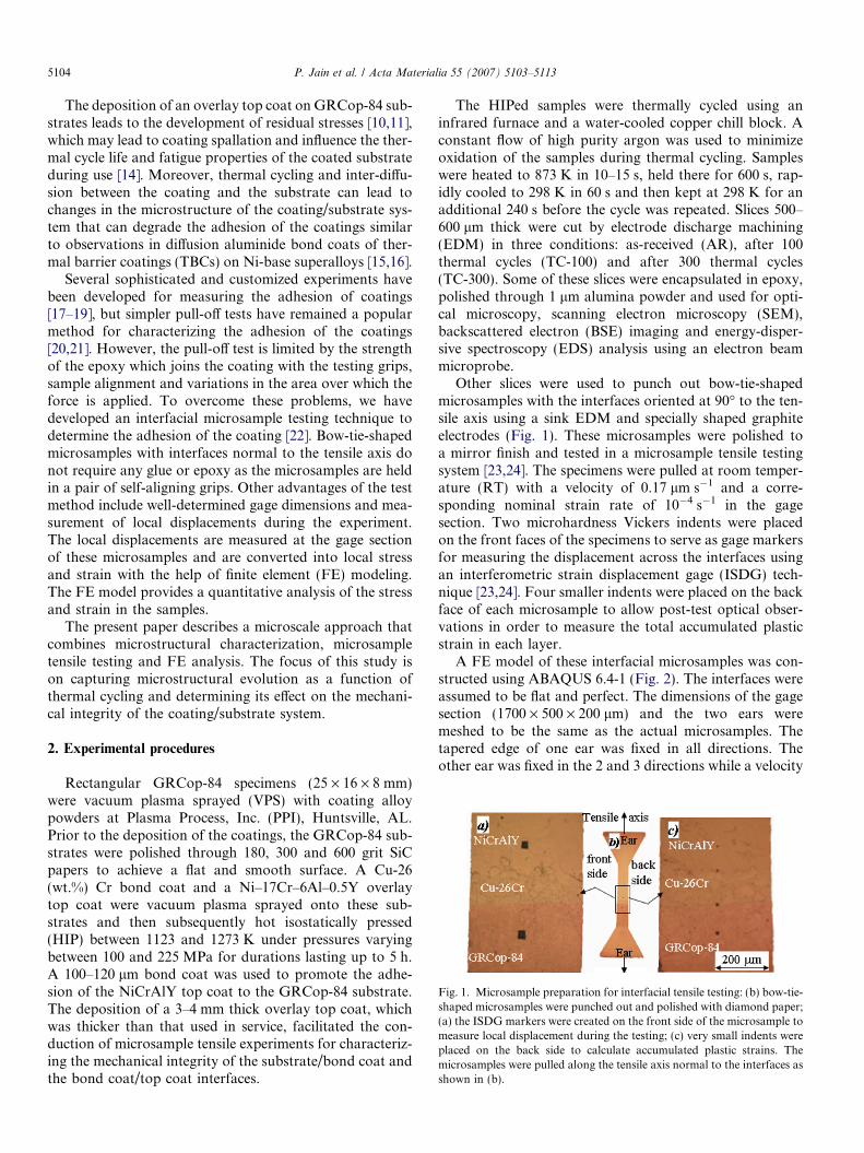
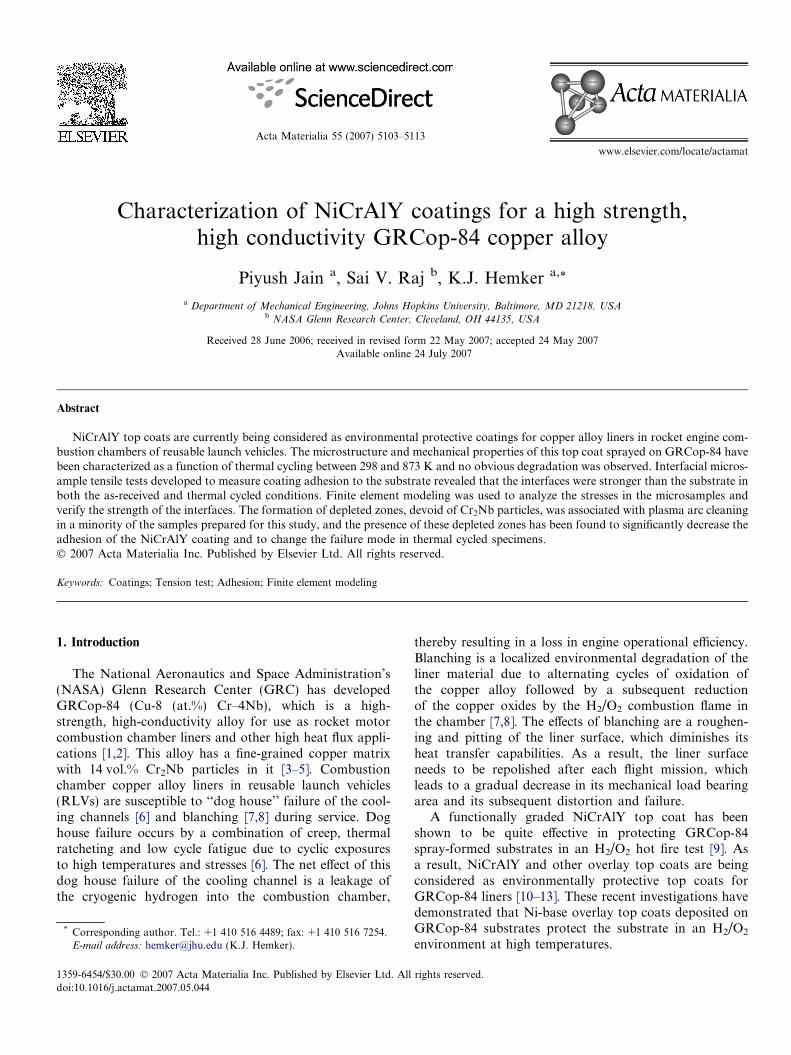
Fig. 1. Microsample preparation for interfacial tensile testing: (b) bow-tie-shaped microsamples were punched out and polished with diamond paper;(a) the ISDG markers were created on the front side of the microsample tomeasure local displacement during the testing; (c) very small indents wereplaced on the back side to calculate accumulated plastic strains. Themicrosamples were pulled along the tensile axis normal to the interfaces asshown in (b).
5104 P. Jain et al. / Acta Materialia 55 (2007) 5103–5113
The deposition of an overlay top coat on GRCop-84 sub-strates leads to the development of residual stresses [10,11],which may lead to coating spallation and influence the ther-mal cycle life and fatigue properties of the coated substrateduring use [14]. Moreover, thermal cycling and inter-diffu-sion between the coating and the substrate can lead tochanges in the microstructure of the coating/substrate sys-tem that can degrade the adhesion of the coatings similarto observations in diffusion aluminide bond coats of ther-mal barrier coatings (TBCs) on Ni-base superalloys [15,16].
Several sophisticated and customized experiments havebeen developed for measuring the adhesion of coatings[17–19], but simpler pull-off tests have remained a popularmethod for characterizing the adhesion of the coatings[20,21]. However, the pull-off test is limited by the strengthof the epoxy which joins the coating with the testing grips,sample alignment and variations in the area over which theforce is applied. To overcome these problems, we havedeveloped an interfacial microsample testing technique todetermine the adhesion of the coating [22]. Bow-tie-shapedmicrosamples with interfaces normal to the tensile axis donot require any glue or epoxy as the microsamples are heldin a pair of self-aligning grips. Other advantages of the testmethod include well-determined gage dimensions and mea-surement of local displacements during the experiment.The local displacements are measured at the gage sectionof these microsamples and are converted into local stressand strain with the help of finite element (FE) modeling.The FE model provides a quantitative analysis of the stressand strain in the samples.
The present paper describes a microscale approach thatcombines microstructural characterization, microsampletensile testing and FE analysis. The focus of this study ison capturing microstructural evolution as a function ofthermal cycling and determining its effect on the mechani-cal integrity of the coating/substrate system.
2. Experimental procedures
Rectangular GRCop-84 specimens (25 · 16 · 8 mm)were vacuum plasma sprayed (VPS) with coating alloypowders at Plasma Process, Inc. (PPI), Huntsville, AL.Prior to the deposition of the coatings, the GRCop-84 sub-strates were polished through 180, 300 and 600 grit SiCpapers to achieve a flat and smooth surface. A Cu-26(wt.%) Cr bond coat and a Ni–17Cr–6Al–0.5Y overlaytop coat were vacuum plasma sprayed onto these sub-strates and then subsequently hot isostatically pressed(HIP) between 1123 and 1273 K under pressures varyingbetween 100 and 225 MPa for durations lasting up to 5 h.A 100–120 lm bond coat was used to promote the adhe-sion of the NiCrAlY top coat to the GRCop-84 substrate.The deposition of a 3–4 mm thick overlay top coat, whichwas thicker than that used in service, facilitated the con-duction of microsample tensile experiments for characteriz-ing the mechanical integrity of the substrate/bond coat andthe bond coat/top coat interfaces.
The HIPed samples were thermally cycled using aninfrared furnace and a water-cooled copper chill block. Aconstant flow of high purity argon was used to minimizeoxidation of the samples during thermal cycling. Sampleswere heated to 873 K in 10–15 s, held there for 600 s, rap-idly cooled to 298 K in 60 s and then kept at 298 K for anadditional 240 s before the cycle was repeated. Slices 500–600 lm thick were cut by electrode discharge machining(EDM) in three conditions: as-received (AR), after 100thermal cycles (TC-100) and after 300 thermal cycles(TC-300). Some of these slices were encapsulated in epoxy,polished through 1 lm alumina powder and used for opti-cal microscopy, scanning electron microscopy (SEM),backscattered electron (BSE) imaging and energy-disper-sive spectroscopy (EDS) analysis using an electron beammicroprobe.
Other slices were used to punch out bow-tie-shapedmicrosamples with the interfaces oriented at 90� to the ten-sile axis using a sink EDM and specially shaped graphiteelectrodes (Fig. 1). These microsamples were polished toa mirror finish and tested in a microsample tensile testingsystem [23,24]. The specimens were pulled at room temper-ature (RT) with a velocity of 0.17 lm s�1 and a corre-sponding nominal strain rate of 10�4 s�1 in the gagesection. Two microhardness Vickers indents were placedon the front faces of the specimens to serve as gage markersfor measuring the displacement across the interfaces usingan interferometric strain displacement gage (ISDG) tech-nique [23,24]. Four smaller indents were placed on the backface of each microsample to allow post-test optical obser-vations in order to measure the total accumulated plasticstrain in each layer.
A FE model of these interfacial microsamples was con-structed using ABAQUS 6.4-1 (Fig. 2). The interfaces wereassumed to be flat and perfect. The dimensions of the gagesection (1700 · 500 · 200 lm) and the two ears weremeshed to be the same as the actual microsamples. Thetapered edge of one ear was fixed in all directions. Theother ear was fixed in the 2 and 3 directions while a velocity
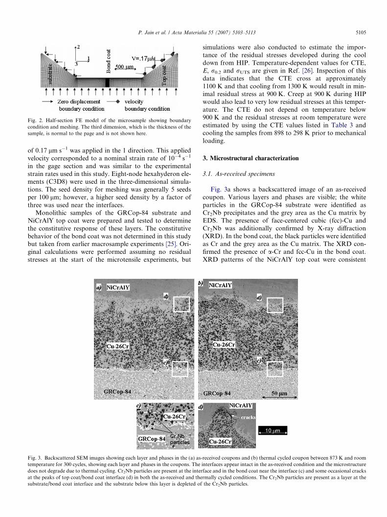
Fig. 2. Half-section FE model of the microsample showing boundarycondition and meshing. The third dimension, which is the thickness of thesample, is normal to the page and is not shown here.
P. Jain et al. / Acta Materialia 55 (2007) 5103–5113 5105
of 0.17 lm s�1 was applied in the 1 direction. This appliedvelocity corresponded to a nominal strain rate of 10�4 s�1
in the gage section and was similar to the experimentalstrain rates used in this study. Eight-node hexahyderon ele-ments (C3D8) were used in the three-dimensional simula-tions. The seed density for meshing was generally 5 seedsper 100 lm; however, a higher seed density by a factor ofthree was used near the interfaces.
Monolithic samples of the GRCop-84 substrate andNiCrAlY top coat were prepared and tested to determinethe constitutive response of these layers. The constitutivebehavior of the bond coat was not determined in this studybut taken from earlier macrosample experiments [25]. Ori-ginal calculations were performed assuming no residualstresses at the start of the microtensile experiments, but
Fig. 3. Backscattered SEM images showing each layer and phases in the (a) as-temperature for 300 cycles, showing each layer and phases in the coupons. Thedoes not degrade due to thermal cycling. Cr2Nb particles are present at the interat the peaks of top coat/bond coat interface (d) in both the as-received and thesubstrate/bond coat interface and the substrate below this layer is depleted of
simulations were also conducted to estimate the impor-tance of the residual stresses developed during the cooldown from HIP. Temperature-dependent values for CTE,E, r0.2 and rUTS are given in Ref. [26]. Inspection of thisdata indicates that the CTE cross at approximately1100 K and that cooling from 1300 K would result in min-imal residual stress at 900 K. Creep at 900 K during HIPwould also lead to very low residual stresses at this temper-ature. The CTE do not depend on temperature below900 K and the residual stresses at room temperature wereestimated by using the CTE values listed in Table 3 andcooling the samples from 898 to 298 K prior to mechanicalloading.
3. Microstructural characterization
3.1. As-received specimens
Fig. 3a shows a backscattered image of an as-receivedcoupon. Various layers and phases are visible; the whiteparticles in the GRCop-84 substrate were identified asCr2Nb precipitates and the grey area as the Cu matrix byEDS. The presence of face-centered cubic (fcc)-Cu andCr2Nb was additionally confirmed by X-ray diffraction(XRD). In the bond coat, the black particles were identifiedas Cr and the grey area as the Cu matrix. The XRD con-firmed the presence of a-Cr and fcc-Cu in the bond coat.XRD patterns of the NiCrAlY top coat were consistent
received coupons and (b) thermal cycled coupon between 873 K and roominterfaces appear intact in the as-received condition and the microstructureface and in the bond coat near the interface (c) and some occasional cracksrmally cycled conditions. The Cr2Nb particles are present as a layer at thethe Cr2Nb particles.
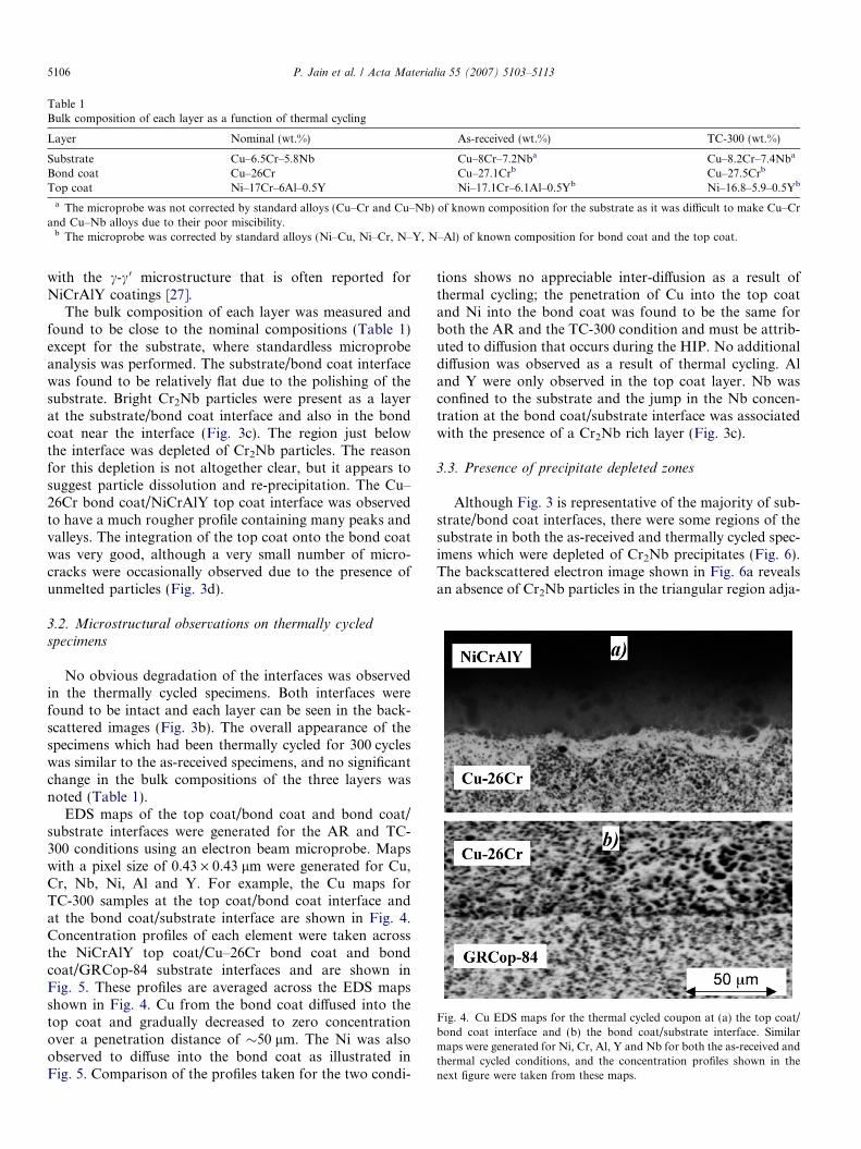
Fig. 4. Cu EDS maps for the thermal cycled coupon at (a) the top coat/bond coat interface and (b) the bond coat/substrate interface. Similarmaps were generated for Ni, Cr, Al, Y and Nb for both the as-received andthermal cycled conditions, and the concentration profiles shown in thenext figure were taken from these maps.
Table 1Bulk composition of each layer as a function of thermal cycling
Layer Nominal (wt.%) As-received (wt.%) TC-300 (wt.%)
Substrate Cu–6.5Cr–5.8Nb Cu–8Cr–7.2Nba Cu–8.2Cr–7.4Nba
Bond coat Cu–26Cr Cu–27.1Crb Cu–27.5Crb
Top coat Ni–17Cr–6Al–0.5Y Ni–17.1Cr–6.1Al–0.5Yb Ni–16.8–5.9–0.5Yb
a The microprobe was not corrected by standard alloys (Cu–Cr and Cu–Nb) of known composition for the substrate as it was difficult to make Cu–Crand Cu–Nb alloys due to their poor miscibility.
b The microprobe was corrected by standard alloys (Ni–Cu, Ni–Cr, N–Y, N–Al) of known composition for bond coat and the top coat.
5106 P. Jain et al. / Acta Materialia 55 (2007) 5103–5113
with the c-c 0 microstructure that is often reported forNiCrAlY coatings [27].
The bulk composition of each layer was measured andfound to be close to the nominal compositions (Table 1)except for the substrate, where standardless microprobeanalysis was performed. The substrate/bond coat interfacewas found to be relatively flat due to the polishing of thesubstrate. Bright Cr2Nb particles were present as a layerat the substrate/bond coat interface and also in the bondcoat near the interface (Fig. 3c). The region just belowthe interface was depleted of Cr2Nb particles. The reasonfor this depletion is not altogether clear, but it appears tosuggest particle dissolution and re-precipitation. The Cu–26Cr bond coat/NiCrAlY top coat interface was observedto have a much rougher profile containing many peaks andvalleys. The integration of the top coat onto the bond coatwas very good, although a very small number of micro-cracks were occasionally observed due to the presence ofunmelted particles (Fig. 3d).
3.2. Microstructural observations on thermally cycled
specimens
No obvious degradation of the interfaces was observedin the thermally cycled specimens. Both interfaces werefound to be intact and each layer can be seen in the back-scattered images (Fig. 3b). The overall appearance of thespecimens which had been thermally cycled for 300 cycleswas similar to the as-received specimens, and no significantchange in the bulk compositions of the three layers wasnoted (Table 1).
EDS maps of the top coat/bond coat and bond coat/substrate interfaces were generated for the AR and TC-300 conditions using an electron beam microprobe. Mapswith a pixel size of 0.43 · 0.43 lm were generated for Cu,Cr, Nb, Ni, Al and Y. For example, the Cu maps forTC-300 samples at the top coat/bond coat interface andat the bond coat/substrate interface are shown in Fig. 4.Concentration profiles of each element were taken acrossthe NiCrAlY top coat/Cu–26Cr bond coat and bondcoat/GRCop-84 substrate interfaces and are shown inFig. 5. These profiles are averaged across the EDS mapsshown in Fig. 4. Cu from the bond coat diffused into thetop coat and gradually decreased to zero concentrationover a penetration distance of �50 lm. The Ni was alsoobserved to diffuse into the bond coat as illustrated inFig. 5. Comparison of the profiles taken for the two condi-
tions shows no appreciable inter-diffusion as a result ofthermal cycling; the penetration of Cu into the top coatand Ni into the bond coat was found to be the same forboth the AR and the TC-300 condition and must be attrib-uted to diffusion that occurs during the HIP. No additionaldiffusion was observed as a result of thermal cycling. Aland Y were only observed in the top coat layer. Nb wasconfined to the substrate and the jump in the Nb concen-tration at the bond coat/substrate interface was associatedwith the presence of a Cr2Nb rich layer (Fig. 3c).
3.3. Presence of precipitate depleted zones
Although Fig. 3 is representative of the majority of sub-strate/bond coat interfaces, there were some regions of thesubstrate in both the as-received and thermally cycled spec-imens which were depleted of Cr2Nb precipitates (Fig. 6).The backscattered electron image shown in Fig. 6a revealsan absence of Cr2Nb particles in the triangular region adja-
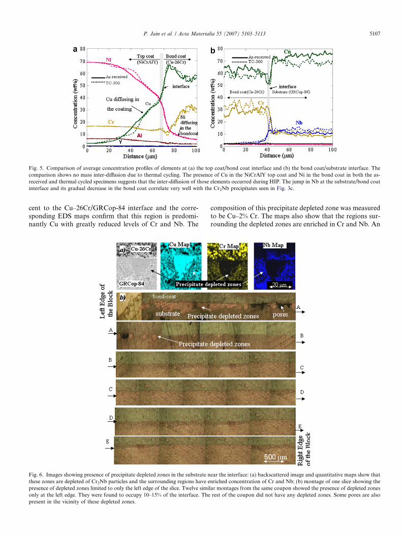
Fig. 5. Comparison of average concentration profiles of elements at (a) the top coat/bond coat interface and (b) the bond coat/substrate interface. Thecomparison shows no mass inter-diffusion due to thermal cycling. The presence of Cu in the NiCrAlY top coat and Ni in the bond coat in both the as-received and thermal cycled specimens suggests that the inter-diffusion of those elements occurred during HIP. The jump in Nb at the substrate/bond coatinterface and its gradual decrease in the bond coat correlate very well with the Cr2Nb precipitates seen in Fig. 3c.
P. Jain et al. / Acta Materialia 55 (2007) 5103–5113 5107
cent to the Cu–26Cr/GRCop-84 interface and the corre-sponding EDS maps confirm that this region is predomi-nantly Cu with greatly reduced levels of Cr and Nb. The
Fig. 6. Images showing presence of precipitate depleted zones in the substrate nthese zones are depleted of Cr2Nb particles and the surrounding regions have epresence of depleted zones limited to only the left edge of the slice. Twelve simionly at the left edge. They were found to occupy 10–15% of the interface. Thepresent in the vicinity of these depleted zones.
composition of this precipitate depleted zone was measuredto be Cu–2% Cr. The maps also show that the regions sur-rounding the depleted zones are enriched in Cr and Nb. An
ear the interface: (a) backscattered image and quantitative maps show thatnriched concentration of Cr and Nb; (b) montage of one slice showing thelar montages from the same coupon showed the presence of depleted zones
rest of the coupon did not have any depleted zones. Some pores are also
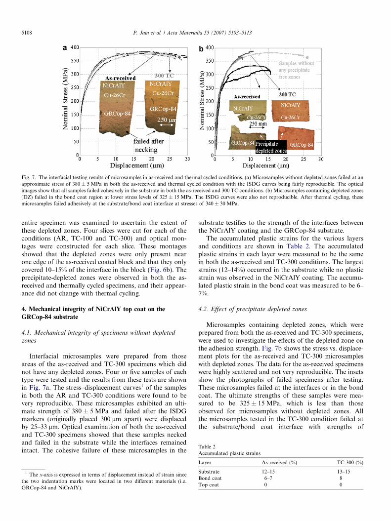
Fig. 7. The interfacial testing results of microsamples in as-received and thermal cycled conditions. (a) Microsamples without depleted zones failed at anapproximate stress of 380 ± 5 MPa in both the as-received and thermal cycled condition with the ISDG curves being fairly reproducible. The opticalimages show that all samples failed cohesively in the substrate in both the as-received and 300 TC conditions. (b) Microsamples containing depleted zones(DZ) failed in the bond coat region at lower stress levels of 325 ± 15 MPa. The ISDG curves were also not reproducible. After thermal cycling, thesemicrosamples failed adhesively at the substrate/bond coat interface at stresses of 340 ± 30 MPa.
Table 2Accumulated plastic strains
5108 P. Jain et al. / Acta Materialia 55 (2007) 5103–5113
entire specimen was examined to ascertain the extent ofthese depleted zones. Four slices were cut for each of theconditions (AR, TC-100 and TC-300) and optical mon-tages were constructed for each slice. These montagesshowed that the depleted zones were only present nearone edge of the as-received coated block and that they onlycovered 10–15% of the interface in the block (Fig. 6b). Theprecipitate-depleted zones were observed in both the as-received and thermally cycled specimens, and their appear-ance did not change with thermal cycling.
4. Mechanical integrity of NiCrAlY top coat on the
GRCop-84 substrate
4.1. Mechanical integrity of specimens without depleted
zones
Interfacial microsamples were prepared from thoseareas of the as-received and TC-300 specimens which didnot have any depleted zones. Four or five samples of eachtype were tested and the results from these tests are shownin Fig. 7a. The stress–displacement curves1 of the samplesin both the AR and TC-300 conditions were found to bevery reproducible. These microsamples exhibited an ulti-mate strength of 380 ± 5 MPa and failed after the ISDGmarkers (originally placed 300 lm apart) were displacedby 25–33 lm. Optical examination of both the as-receivedand TC-300 specimens showed that these samples neckedand failed in the substrate while the interfaces remainedintact. The cohesive failure of these microsamples in the
1 The x-axis is expressed in terms of displacement instead of strain sincethe two indentation marks were located in two different materials (i.e.GRCop-84 and NiCrAlY).
substrate testifies to the strength of the interfaces betweenthe NiCrAlY coating and the GRCop-84 substrate.
The accumulated plastic strains for the various layersand conditions are shown in Table 2. The accumulatedplastic strains in each layer were measured to be the samein both the as-received and TC-300 conditions. The largeststrains (12–14%) occurred in the substrate while no plasticstrain was observed in the NiCrAlY coating. The accumu-lated plastic strain in the bond coat was measured to be 6–7%.
4.2. Effect of precipitate depleted zones
Microsamples containing depleted zones, which wereprepared from both the as-received and TC-300 specimens,were used to investigate the effects of the depleted zone onthe adhesion strength. Fig. 7b shows the stress vs. displace-ment plots for the as-received and TC-300 microsampleswith depleted zones. The data for the as-received specimenswere highly scattered and not very reproducible. The insetsshow the photographs of failed specimens after testing.These microsamples failed at the interfaces or in the bondcoat. The ultimate strengths of these samples were mea-sured to be 325 ± 15 MPa, which is less than thoseobserved for microsamples without depleted zones. Allthe microsamples tested in the TC-300 condition failed atthe substrate/bond coat interface with strengths of
Layer As-received (%) TC-300 (%)
Substrate 12–15 13–15Bond coat 6–7 8Top coat 0 0
P. Jain et al. / Acta Materialia 55 (2007) 5103–5113 5109
340 ± 30 MPa. The plots for these failures were very repro-ducible with the measured ISDG displacement of markers(originally placed 300 lm apart) measured to be only 5–9 lm.
5. Constitutive behavior of substrate, bond coat and top coat
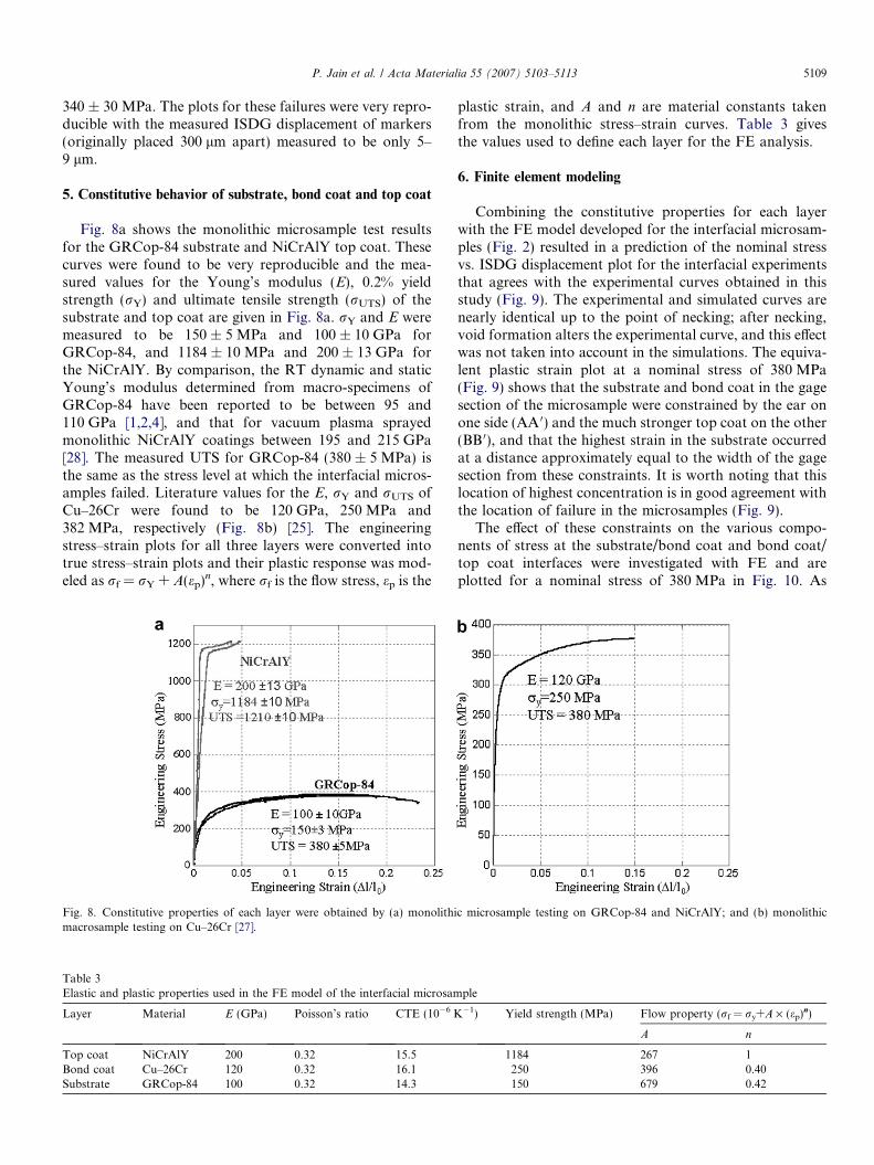
Fig. 8a shows the monolithic microsample test resultsfor the GRCop-84 substrate and NiCrAlY top coat. Thesecurves were found to be very reproducible and the mea-sured values for the Young’s modulus (E), 0.2% yieldstrength (rY) and ultimate tensile strength (rUTS) of thesubstrate and top coat are given in Fig. 8a. rY and E weremeasured to be 150 ± 5 MPa and 100 ± 10 GPa forGRCop-84, and 1184 ± 10 MPa and 200 ± 13 GPa forthe NiCrAlY. By comparison, the RT dynamic and staticYoung’s modulus determined from macro-specimens ofGRCop-84 have been reported to be between 95 and110 GPa [1,2,4], and that for vacuum plasma sprayedmonolithic NiCrAlY coatings between 195 and 215 GPa[28]. The measured UTS for GRCop-84 (380 ± 5 MPa) isthe same as the stress level at which the interfacial micros-amples failed. Literature values for the E, rY and rUTS ofCu–26Cr were found to be 120 GPa, 250 MPa and382 MPa, respectively (Fig. 8b) [25]. The engineeringstress–strain plots for all three layers were converted intotrue stress–strain plots and their plastic response was mod-eled as rf = rY + A(ep)n, where rf is the flow stress, ep is the
Fig. 8. Constitutive properties of each layer were obtained by (a) monolithimacrosample testing on Cu–26Cr [27].
Table 3Elastic and plastic properties used in the FE model of the interfacial microsam
Layer Material E (GPa) Poisson’s ratio CTE (10�6 K
Top coat NiCrAlY 200 0.32 15.5Bond coat Cu–26Cr 120 0.32 16.1Substrate GRCop-84 100 0.32 14.3
plastic strain, and A and n are material constants takenfrom the monolithic stress–strain curves. Table 3 givesthe values used to define each layer for the FE analysis.
6. Finite element modeling
Combining the constitutive properties for each layerwith the FE model developed for the interfacial microsam-ples (Fig. 2) resulted in a prediction of the nominal stressvs. ISDG displacement plot for the interfacial experimentsthat agrees with the experimental curves obtained in thisstudy (Fig. 9). The experimental and simulated curves arenearly identical up to the point of necking; after necking,void formation alters the experimental curve, and this effectwas not taken into account in the simulations. The equiva-lent plastic strain plot at a nominal stress of 380 MPa(Fig. 9) shows that the substrate and bond coat in the gagesection of the microsample were constrained by the ear onone side (AA 0) and the much stronger top coat on the other(BB 0), and that the highest strain in the substrate occurredat a distance approximately equal to the width of the gagesection from these constraints. It is worth noting that thislocation of highest concentration is in good agreement withthe location of failure in the microsamples (Fig. 9).
The effect of these constraints on the various compo-nents of stress at the substrate/bond coat and bond coat/top coat interfaces were investigated with FE and areplotted for a nominal stress of 380 MPa in Fig. 10. As
c microsample testing on GRCop-84 and NiCrAlY; and (b) monolithic
ple
�1) Yield strength (MPa) Flow property (rf = ry+A · (ep)n)
A n
1184 267 1250 396 0.40150 679 0.42

Fig. 9. Comparison of the experimental and simulation results for interfacial microsamples shows that stress vs. displacement plots agreed until thecommencement of the necking and locations of the strain concentration in the equivalent plastic strain plot (b) coincide with the location of failure ofmicrosamples seen in the optical image (c). Equivalent plastic strains plot showing that substrate + bond coat were constrained at sections AA 0 and BB 0,and constraints diminished at distances of the order of the width (�500 lm) of the gauge section. This led to high deformation in the middle sectionbetween AA 0 and BB 0 that led to failure of these samples.
Fig. 10. FE model results at the nominal stress of 380 MPa showing stresscomponents at (a) the substrate/bond coat interface and (b) the bond coat/top coat interface. These results show that the top coat/bond is undercomplex loading due to constraint applied by the top coat. Theseconstraints were lower at the bond coat/top coat interface, which sawmainly tensile loading.
Table 4The true stress components at both interfacial planes when the nominalstress of interfacial microsamples was 380 MPa
Type of interface S11 (tensile)MPa
S12 (shear)MPa
S13 (shear)MPa
Substrate/bond coat 411–483 �57 to 57 �35 to +35Bond coat/top coat 263–565 �264 to 264 �238 to +238
5110 P. Jain et al. / Acta Materialia 55 (2007) 5103–5113
summarized in Table 4, the tensile component (S11) at thebond coat/top coat interface ranged from 263 MPa at themiddle of the microsample to 565 MPa along the edges.Similarly, the magnitude of the shear components (S12
and S13) was highest along the edges and zero in the mid-
dle. These variations highlight the complex loading thatresult from the constraints and confirm the fact that thestrength of the interface is higher than the applied nominalstress. The degree of complexity is expected to be evenhigher in the experimental microsamples where the inter-faces are much rougher than the ideally flat interfaces usedin the simulations.
For the bond coat/substrate interface the calculated ten-sile stress (S11) ranges from 411 to 483 MPa and is higherthan the measured UTS (380 MPa) of the interfacialmicrosamples. The S12 shear component ranged between�57 and 57 MPa, while S13 varied from –35 to +35 MPa.The magnitudes of the shear stresses were calculated tobe much smaller than the tensile component at this inter-face, which suggests that this interface is mainly under ten-sile loading and that its strength is greater than 411 MPa.
FE simulations were conducted to investigate the influ-ence of the CTE mismatch associated with cool down afterthe HIP treatment. The stresses that develop in each of thethree layers upon cooling from 898 to 298 K are shown inFig. 11. The substrate has the lowest CTE and develops abiaxial state of compression, while the bond coat and topcoat are both placed in biaxial tension. The magnitude ofthese biaxial stresses is greatest at the substrate/bond coatinterface and falls off rapidly away from there. The atten-dant axial and shear stresses associated with cooling are
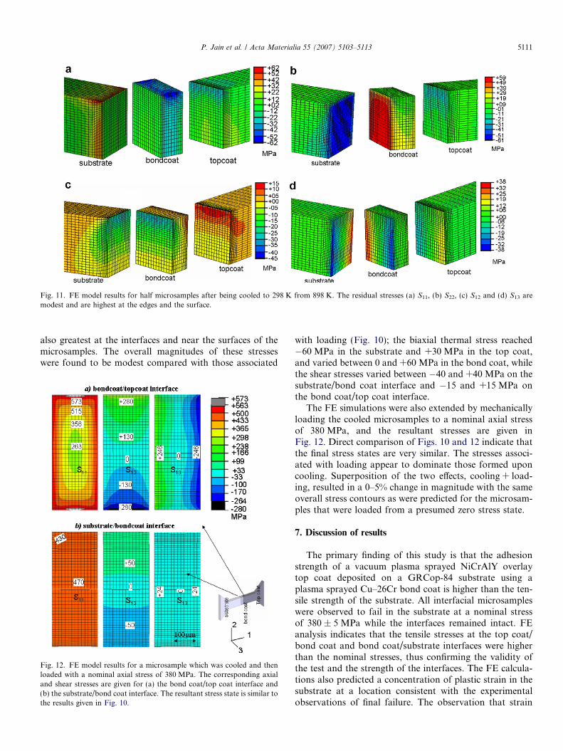
Fig. 11. FE model results for half microsamples after being cooled to 298 K from 898 K. The residual stresses (a) S11, (b) S22, (c) S12 and (d) S13 aremodest and are highest at the edges and the surface.
P. Jain et al. / Acta Materialia 55 (2007) 5103–5113 5111
also greatest at the interfaces and near the surfaces of themicrosamples. The overall magnitudes of these stresseswere found to be modest compared with those associated
Fig. 12. FE model results for a microsample which was cooled and thenloaded with a nominal axial stress of 380 MPa. The corresponding axialand shear stresses are given for (a) the bond coat/top coat interface and(b) the substrate/bond coat interface. The resultant stress state is similar tothe results given in Fig. 10.
with loading (Fig. 10); the biaxial thermal stress reached�60 MPa in the substrate and +30 MPa in the top coat,and varied between 0 and +60 MPa in the bond coat, whilethe shear stresses varied between �40 and +40 MPa on thesubstrate/bond coat interface and �15 and +15 MPa onthe bond coat/top coat interface.
The FE simulations were also extended by mechanicallyloading the cooled microsamples to a nominal axial stressof 380 MPa, and the resultant stresses are given inFig. 12. Direct comparison of Figs. 10 and 12 indicate thatthe final stress states are very similar. The stresses associ-ated with loading appear to dominate those formed uponcooling. Superposition of the two effects, cooling + load-ing, resulted in a 0–5% change in magnitude with the sameoverall stress contours as were predicted for the microsam-ples that were loaded from a presumed zero stress state.
7. Discussion of results
The primary finding of this study is that the adhesionstrength of a vacuum plasma sprayed NiCrAlY overlaytop coat deposited on a GRCop-84 substrate using aplasma sprayed Cu–26Cr bond coat is higher than the ten-sile strength of the substrate. All interfacial microsampleswere observed to fail in the substrate at a nominal stressof 380 ± 5 MPa while the interfaces remained intact. FEanalysis indicates that the tensile stresses at the top coat/bond coat and bond coat/substrate interfaces were higherthan the nominal stresses, thus confirming the validity ofthe test and the strength of the interfaces. The FE calcula-tions also predicted a concentration of plastic strain in thesubstrate at a location consistent with the experimentalobservations of final failure. The observation that strain
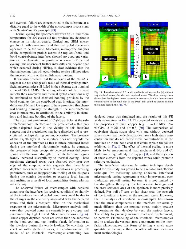
Fig. 13. Two-dimensional FE model results for microsamples: (a) withoutany depleted zones; (b) with two depleted zones. The direct comparisonshows that the depleted zones have strain concentration but do not createconcentration in the bond coat to the extent that could be used to explainthe failure seen in the Fig. 7b.
5112 P. Jain et al. / Acta Materialia 55 (2007) 5103–5113
and eventual failure are concentrated in the substrate at adistance equal to the width of the microsample is consistentwith Saint–Venant’s principle [29].
Thermal cycling the specimens between 873 K and roomtemperature for 300 cycles did not produce any detectablechange in its microstructure. Optical and SEM micro-graphs of both as-received and thermal cycled specimensappeared to be the same. Moreover, microprobe analysesof the composition profiles across the top coat/bond andbond coat/substrate interfaces showed no apparent varia-tions in the elemental compositions as a result of thermalcycling. The absence of further inter-diffusion, beyond thatwhich occurred during HIPing, is clear evidence that thethermal cycling that will occur during service will not affectthe microstructure of the multilayered coating.
It was also observed that the adhesion of the NiCrAlYtop coat did not change as a result of thermal cycling; inter-facial microsamples still failed in the substrate at a nominalstress of 380 ± 5 MPa. The strong adhesion of the top coatin both the as-received and thermal cycled conditions maybe attributed to good chemical bonding provided by thebond coat. At the top coat/bond coat interface, the inter-diffusion of Ni and Cu appear to have promoted this chem-ical bonding. Similarly, the strength of the substrate/bondcoat interface may be attributed to the similarity in chem-istry and intimate bonding of the layers.
The apparent enrichment of Cr2Nb particles at the sub-strate/bond coat interface and the presence of a thin pre-cipitate-depleted layer in the vicinity of this interfacesuggest that the precipitates may have dissolved and re-pre-cipitated, perhaps during coating deposition. The presenceof the Cr2Nb layer at the interface does not degrade theadhesion of the interface as this interface remained intactduring the interfacial microsample testing. By contrast,the presence of large precipitate depleted zones did corre-spond with the lower strength of the interfaces and signif-icantly increased susceptibility to thermal cycling. Theseprecipitate depleted zones were observed only near oneedge of the coupons, which suggests that these largedepleted zones were the result of variations in processingparameters, such as inappropriate tooling of the couponsduring the coating deposition or excessive local heatingand melting as a result of local instabilities during plasmaarc cleaning.
The observed failure of microsamples with depletedzones near the interfaces (as-received condition) or sharplyat the interface (thermal cycled condition) could be due tothe changes in the chemistry associated with the depletedzones and their subsequent effect on the mechanicalresponse of the microsample. Microprobe analysis indi-cates that depleted zones are essentially pure copper andsurrounded by high Cr and Nb concentrations (Fig. 6).These copper-depleted zones are softer than the substrateor the bond coat and may localize plastic deformation atthe interface during the tensile loading. To elucidate theeffect of softer depleted zones, a two-dimensional FEmodel of an interfacial microsample containing two
depleted zones was simulated and the results of this FEanalysis are given in Fig. 13. The depleted zones were giventhe properties of pure copper (e.g. ry = 113 MPa, E=90 GPa, A = 761 and n = 0.8) [30]. The comparison ofequivalent plastic strain plots with and without depletedzones shows that the depleted zones have a high strain con-centration but do not create stress concentrations at theinterface or in the bond coat that could explain the failureexhibited in Fig. 8. The effect of thermal cycling is morelikely to be environmental than mechanical. Nb and Crboth have a high affinity for oxygen [31] and the rejectionof these elements from the depleted zones could promoteselective oxidation.
The interfacial microsample testing technique devel-oped for this study has proven to be a reliable and efficienttechnique for measuring coating adhesion. Interfacialmicrosample testing represents a clear improvement overtraditional pull-off testing because: it is not limited bythe strength of the epoxy; the test is easier to align; andthe cross-sectional area of the specimen is more preciselydefined. For pull-off tests or lap shear tests the strengthof the interface is taken as the nominal stress. However,the FE analysis of interfacial microsamples has shownthat the stress components at the interfaces are actuallymuch different than the nominal stress, mainly becauseof constraints that develop between the various layers.The ability to precisely measure load and displacement,to perform FE modeling of the interfacial microsamplesand to analyze the various stress components on the inter-facial planes makes this form of testing a much morequantitative technique than the other adhesion measure-ment methodologies.
P. Jain et al. / Acta Materialia 55 (2007) 5103–5113 5113
8. Summary and conclusions
A novel microsample technique has been developed andused to characterize the interfacial strength of NiCrAlYoverlay coated GRCop-84 samples with a Cu–26% Crbond coat. This technique was combined with microstruc-tural characterization and FE analysis, and the key resultsof this study can be summarized as follows:
1. The adhesion strength of the vacuum plasma sprayedNiCrAlY top coat has been determined to be higherthan the ultimate tensile strength of the GRCop-84substrate.
2. Thermal cycling between RT and 873 K for 300 cyclesdid not have a measurable effect on the microstructureor the adhesion strength of this multilayered environ-mental coating.
3. The presence of local depleted zones in the substratenear to the Cu–26Cr/GRCop-84 interface was associ-ated with undesirable variations in processing. Thesedepleted zones were associated with lower interfacialstrength, changed the failure mode in the microsamplesand increased the susceptibility to thermal cycling.
4. FE models developed to capture the complex nature ofthe deformation of these multilayered samples con-firmed that the strength of the interfaces were indeedgreater than the nominal stress of the interfacial micros-ample. The FE results also show that the stresses on thesubstrate/bond coat interface were relatively tensile anduniform, while the stress on the bond coat/top coatinterface is much more complex and non-uniform,primarily as a result of the constraints imposed by theNiCrAlY top coat.
Acknowledgements
This Project was funded by the NASA Glenn ResearchCenter under the Low Emissions Alternative Power(LEAP) Propulsion Program (under Contract No. NRA-01-GRC-02). The assistance of Dr. Ken Livi in obtainingmicroprobe results is greatly appreciated.
References
[1] Ellis DL, Michal GM. NASA-CR-185144. Cleveland, OH: NASALewis Research Center; 1989.
[2] Ellis DL, Michal GM. NASA-CR-198529. Cleveland, OH: NASALewis Research Center; 1996.
[3] Anderson KR, Groza JR, Ellis D. Metall Mater Trans A1995;26:2197–206.
[4] Ellis D, Keller D. NASA-CR-210055. Cleveland, OH: NASA GlennResearch Center; 2000.
[5] Ellis DL, Dreshfield RL, Ulmer DG. PPM conference proceed-ings. Cleveland, OH: NASA Lewis Research Center; 1997.
[6] Quentmeyer RJ. NASA-TM-X-73665. Cleveland, OH: LewisResearch Center; 1977.
[7] Morgan DB, Kobayashi AC. NASA-CR-184345. Huntsville,AL: NASA Marshall Space Flight Center; 1989.
[8] Rosenberg SD et al. Jet Propul Power 1992;8:1200–7.[9] Elam S, Holmes R, McKechnie T, Hickman R, Pickens T. In: 52nd
JANAF Propulsion Meeting/1st Liquid Propulsion SubcommitteeMeeting, Las Vegas, Chemical Propulsion Information Agency, TheJohns Hopkins University, Baltimore, MD; 2004. p. 1–10.
[10] Ghosn LJ, Raj SV. Ceram Engng Sci Proc 2002;23:409–16.[11] Raj SV, Ghosn LJ, Agarwal A, Lachtrup TP. Surface engineering in
materials science II, TMS annual meeting, San Diego, CA; 2003. p.49–56.
[12] Nathal MV, Ellis DL, Loewenthal WS, Raj SV, Thomas-Ogbuji LU,Ghosn J, Greenbauer-Seng LA, et al. In the JANNAF 39th CS/27thAPS/21st PSHS/3rd MSS subcommittee joint meeting, ColoradoSprings, CO, CD-ROM, (Dec 2003), p. 2003-0390CB.
[13] Raj SV. Blanch resistant and thermal barrier NiAl coating systems foradvanced copper alloys US Patent No. 6,838,191; 2005.
[14] Gunnars J, Alahelisten A. Surf Coat Technol 1996;80:303–12.[15] Pan D, Chen MW, Hemker KJ. Acta Mater 2003;51:2205–17.[16] Chen MW, Livi KJT, Hemker KJ. Metall Mater Trans A
2003;34A:2289–99.[17] Rickerby DS. Surf Coat Technol 1988;36:541–57.[18] Chalker PR, Bull SJ, Rickerby DS. Mater Sci Engng A
1991;140:583–92.[19] Volinsky AA, Moody NR, Gerberich WW. Acta Mater
2002;50:441–66.[20] Jacobson R. Thin Solid Films 1976;33:191–202.[21] Katz G. Thin Solid Films 1976;33:99–110.[22] Jain P, Hemker KJ, Raj Sai V. TMS Lett 2004;1:171–2.[23] Sharpe Jr WN. NASA-TM-101638. Hampton, VA: NASA Langley
Research Center; 1989.[24] Sharpe Jr WN. Opt Engng 1982;21:483–8.[25] Raj SV. Unpublished research. Cleveland, OH: NASA Glenn
Research Center; 2005.[26] Raj SV, Ghosn LJ, Robinson C, Humphrey D. Mater Sci Engng A
2007;457:300–12.[27] Wang B, Wen LS. Mater Sci Engng A 2003;357:39–44.[28] Lerch B, Raj SV. unpublished research. Cleveland, OH: NASA Glenn
Research Center; 2005.[29] Hibbeler RC. Mech Mater. Englewood Cliffs, NJ: Prentice Hall;
1997.[30] Wang YM, Ma E. Acta Mater 2004;52:1699–709.[31] Ashby Michael F, Jones David RH. Engng Mater 1. Oxford: But-
terworth-Heinemann; 1996.