characterization and mathematical modelling of single fluidised particle coating
TRANSCRIPT
This article appeared in a journal published by Elsevier. The attachedcopy is furnished to the author for internal non-commercial researchand education use, including for instruction at the authors institution
and sharing with colleagues.
Other uses, including reproduction and distribution, or selling orlicensing copies, or posting to personal, institutional or third party
websites are prohibited.
In most cases authors are permitted to post their version of thearticle (e.g. in Word or Tex form) to their personal website orinstitutional repository. Authors requiring further information
regarding Elsevier’s archiving and manuscript policies areencouraged to visit:
http://www.elsevier.com/copyright

Author's personal copy
Characterization and mathematical modelling of single fluidised particle coating
Stina Karlsson a,1, Anders Rasmuson a,⁎, Ingela Niklasson Björn b, Staffan Schantz b
a Department of Chemical and Biological Engineering, Chalmers University of Technology, SE-412 96 Gothenburg, Swedenb AstraZeneca Pharmaceutical and Analytical R&D, Mölndal, SE-431 83 Mölndal, Sweden
a b s t r a c ta r t i c l e i n f o
Article history:Received 2 February 2010Received in revised form 28 September 2010Accepted 5 November 2010Available online 12 November 2010
Keywords:Single particleCoatingFluidised bedDropletLatex dispersionAFM
A study was made of coating single particles with water-based dispersions under realistic fluid dynamic andwell-defined operating conditions. The surfaces of the coated particles were observed with atomic forcemicroscopy (AFM) and scanning electronmicroscopy (SEM). AFMwas used to study the latex particle packingand the colloid particle coalescence at the nanoscale, while SEMwas used to study the film at the droplet sizelevel. The influence of temperature, moisture content and spray rate were investigated.The experiments showed a coating layer built up of rings of colloid particles for all cases studied except forhigh spray rate. A variation in the degree of coalescence between colloid particles with different glasstransition temperatures, Tg, was shown in AFM. Cracks in the coating layer were observed when thetemperature was lower than Tg.Mechanism evaluation using dimensionless numbers showed that a droplet will spread to the equilibriumangle without splashing; the colloid particles accumulate at the interface between the liquid and the air for allcases studied except air with 90% RH and 20 °C and a wet-bulb temperature in the coating layer. Theevaluation indicated that no skin forms in any of the cases. A model of the drying of a single droplet wasdeveloped to describe the experimental results with rings of colloid particles. The simulation of the shape andheight of the dried droplet agrees well with the experimental results.
© 2010 Elsevier B.V. All rights reserved.
1. Introduction
Coating is a common process step in the chemical, agricultural,pharmaceutical and food industries. Coating of solid particles is usedfor sustained release of active components, protection of the corefrom external conditions, taste or odor masking and easier powderhandling. In particular, several applications are used for coating in thepharmaceutical industry, both aesthetic and functional.
The final coating properties depend not only on the coatingmaterial but also on the process equipment and the operatingconditions during film formation. The spray rate, temperature andmoisture content are operating parameters that influence the finalcoating and can be varied in the process. The process equipment forfilm coating in the pharmaceutical industry can be divided into twomain groups: rotating drums and fluidised beds. Fluidised beds can befurther divided into top-spray, tangential-spray and bottom-sprayequipment. The coating of high quality particles is often done in aWurster bed, Fig. 1. A Wurster bed is a circulating fluidised bed withbottom-spray equipment. The design of the Wurster bed forces theparticles to circulate in the bed, which facilitates an even distributionof the wetting and drying time between particles. The particle
dynamics in the bed and the residence time in the wetting and dryingregions of the bed influence the drying rate and the final coating.
Several processes take place simultaneously at the single-particlelevel during the coating phase. These are: the atomization of thecoating solution, transport of the droplets formed to the particle,adhesion of the droplets to the particle surface, film formation anddrying. The processes are repeated for each film layer applied. Earlierstudies showed that the process parameters have a strong influenceon the quality and the quantity of the coating deposited [1–4]. Thismakes it difficult to use a fluidized bed as an experimental set-up withthe intention of determining the underlying mechanisms that governthe coating process at a single-particle level.
Link and Schlünder [5] approach this problem by scaling down theprocess to its smallest component, a single particle. They introduce alaboratory scale apparatus in which a single, freely levitated particlecan be coated under well-defined and constant drying conditions, i.e.with constant flow and temperature but a gas that is dry. The mainpart consists of a coating chamber that contains the capillary tube forlevitating the particle and the top-spray nozzle for supplying andatomizing the liquid feed. The influence of the product and operatingvariables on coating growth rate and morphology were studied. In alater work [6] further experiments were made to study the influenceof process parameters, drying conditions, impact velocities andphysical properties of sprayed solutions on the kinetics of granulationat a single-particle scale. However, this apparatus limits studies totop-spray coating. Ström et al. [7] presented a device for coating a
Powder Technology 207 (2011) 245–256
⁎ Corresponding author. Tel.: +46 31 772 29 40; fax: +46 31 772 30 35.E-mail address: [email protected] (A. Rasmuson).
1 Present address: Epsilon Utvecklingscentrum Väst, Lindholmspiren 9, SE-417 56Göteborg, Sweden.
0032-5910/$ – see front matter © 2010 Elsevier B.V. All rights reserved.doi:10.1016/j.powtec.2010.11.006
Contents lists available at ScienceDirect
Powder Technology
j ourna l homepage: www.e lsev ie r.com/ locate /powtec

Author's personal copy
single particle with bottom-spray equipment, as in the Wursterprocess. The droplets are carried by the air stream, which influencesthe droplet's deposition on the particle surface. In the device, thetemperature and humidity of the drying gas and, by using ink-jettechnology, the single droplet size, velocity and frequency can bevaried, thus obtaining a well-defined coating process.
Water-based latex dispersion as a coating material is an environ-mentally friendly alternative to volatile organic solvent borne coat-ings. There has been a lot of research in the past 20 years to minimizethe use of volatile organic compounds, andmany recent studies reportfilm formation of water-borne latex dispersion on flat surfaces, assummarized by Kiil [8].
Drying and film formation of latex dispersions are often dividedinto three stages. Vanderhoff et al. [9] describe the three stages:evaporation of water brings the colloid particles into close packing,colloid particles are deformed to form a film without voids, anddiffusion of polymer chains across particle interfacesmakes it possibleto obtain a continuous film, Fig. 2.
In the first drying stage, water evaporates from the surface and thefilm dries at a constant rate. Studies in the literature show that theinitial evaporation rate is the same as for purewater [9,10]. The dryingrate depends on the temperature and relative humidity of the air andon the flow and transfer conditions. The dimensionless external masstransfer coefficient, NuAB, is a function of the Reynolds, Re, and theSchmidt, Sc, numbers. Correlations for NuAB can be found in theliterature. Stage 2 begins when the latex colloid particles are closelypacked. The colloid particles deform in stage 2. The maximum volumefraction of spherical particles is 0.74 (ideal face centred cubic, fcc,close-packed). How well the colloid particles pack before thedeformation starts depends on the colloid particle properties and onthe drying rate. Relevant colloid particle properties include the sizedistribution and the inter-particle interactions through the particlesurface properties. The absolute drying rate may influence as wellsince ordering is not instantaneous. The rate of drying decreases
during this stage. In stage 3, the colloid particles coalesce and acontinuous film is formed. The drying rate further decreases and thelast water diffuses through the polymer itself. Stage 3 depends on thetemperature. The minimum film formation temperature, MFFT, is thetemperature above which stage three, diffusion between colloidparticles, occurs and a continuous film is formed. The MFFT for thedispersions depends on the elastic modulus, which is a function of thepolymer composition, the surfactant system and the colloid particlediameter. It has often been observed that the MFFT is approximatelyequal to the glass transition temperature, Tg, of the polymer.
The drying of a film is even more complex than the three stagesdescribed. Parts of a particle surface are often at different dryingstages at the same time, and the stages are not distinctly separated. Inthe process equipment for coating, the coating liquid is sprayed on thesurface as droplets. The convex shape of the droplets deposited on theparticle causes the drying to be inhomogeneous in the lateraldirection.
Two causes of lateral transport are given in the literature. The firstis the transport caused by the concentration gradient of water. At auniform evaporation rate, the convex shape of the droplet gives agradient of water concentration in the lateral direction. The watergradient produces a flux of water towards the edge. The other cause isthe transport of water to retain the shape of a droplet. Deegan et al.[11] assumed that the droplet shape is a spherical cap with a constantdiameter. The constant shape gives a liquid flux towards the edge. Aneveryday observation of lateral drying would be the dark rings formedon a table after a droplet of coffee has dried. The “coffee particles” aretransported laterally to the edge of the droplet, forming the ring.Routh and Russel [12] presented a model of lateral drying thatassumed a drying front starting at the edge and moving towards thecentre.
Parisse and Allain [13] studied twomodels for the drying of colloidsuspension droplets, where they compared the influence of theassumptions of constant contact angle and constant diameter of thedroplet. In the constant angle model, the central part of the dropletwas assumed to be a spherical cap with a constant contact angle. Inthe constant diameter model, the contact angle decreased duringdrying; when the critical concentration was reached at the part at theedge, the flow in and out of this part stopped. A comparison of themodels with experimental results showed that the model with aconstant diameter predicts the profile of the dry droplet better thandid the constant angle model. Ring formation was not observed in thestudy of Parisse and Allain [13].
Deegan et al. [11,14] pointed out the formation of rings whendroplets of dispersion dry and formulated a model for ring formation.Deegan and co-authors used the constant diameter approach, inwhich the droplet is pinned to the three-phase line. The pinned dryinginduces flows inside the droplet from the centre towards the edges;the edges would otherwise dry out and the diameter would decrease.Although they described the qualitative features of the model, nodirect numerical simulations of the ring formation were given.
Drying studies of latex dispersions show that different mecha-nisms control the drying, such as skinning and drying frontmovement. Routh and Russel [15,16] used dimensionless numbersto predict drying regimes and the fundamental mechanisms that areimportant to consider. Kiil [8] reports modelling of latex filmformation including skinning.
Most studies of film formation in the literature are carried out atrelatively low drying rates and on flat surfaces where diffusion ofwater in air is the rate-determined stage. However, processequipment for coating is often a fluidised bed with a high convectivemass transfer rate. The understanding of this mechanism under trueprocess conditions is limited. To gain an understanding of theinfluence of the high drying rate in the fluidised bed process, themain mechanisms were compared to the drying rate. A device forcoating a single levitated particle was used in several experiments to
Fig. 1. Schematic drawings of a Wurster bed, 1: expansion chamber (decelerationregion, fountain), 2: annulus (down bed region), 3: Wurster tube (up bed region),4: distributor plate, 5: spray nozzle.
Fig. 2. The three drying stages in latex film formation.
246 S. Karlsson et al. / Powder Technology 207 (2011) 245–256

Author's personal copy
study the film formation under fluidised conditions. The single-particle coating device is described in detail in Ström et al. [7]. Amodelof coating with water-based dispersion was developed to gain anunderstanding of the formation of the surface structure on particlescoated in fluidised beds under process conditions comparable tocoating in fluidised beds.
2. Material and experimental procedures
2.1. Material
Glass beads of a narrow size distribution (1.12–1.24 mm) wereused as collector particles because of their inert and non-poroussurface and spherical shape. The mean diameter of the particles was1200 μm. Two aqueousmonodisperse latex dispersions were used as acoating agent. The colloid particles consist of methyl methacrylate(MMA) and ethyl acrylate (EA) copolymers stabilized with a non-ionic PEG-methacrylate “surfmer”. A dispersion of SD7G2 with a glasstransition temperature, Tg, above the ambient temperature, andSD5G2 with a Tg below the ambient temperature, were chosen.Schantz et al. [17] report the synthesis of dispersions and a detailedstudy of SD5G2. Themost important characteristics of the dispersions,diluted to 1 wt.%, are given in Table 1.
2.2. Single-particle coating device
A single-particle coating (SPC) device was used to coat theparticles [7]. The particle was aerodynamically levitated in the deviceduring the coating to obtain the same order of mass transfer rate as ina fluidised state. The coating droplets were injected with the gasstream; thus the droplets and the gas were concurrent as in theWurster process. The single-particle coater is an assembly of severalhigh-end techniques that form a complex system with the solepurpose of coating a single particle under controlled conditions. Thecoater consists of a coating chamber, which contains a capillary tubefor levitating the particle, a micro-dispenser for producing discretemicro-droplets of controlled size and velocity, and a device forsupplying gas with specified temperature and humidity, Fig. 3.
A wide variety of process conditions can be simulated owing to theflexibility of the system, from the temperature and moisture contentof the suspending air and the flow rate of the coating suspensiondown to the single droplet level. Droplets of typically 50–100 pL areejected from the nozzle giving an equivalent droplet diameter ofapproximately 50 μm. Detailed information on the generation of thedroplets is given in Laurell et al. [23].
2.3. Characterization
An atomic force microscopy, AFM, analysis was carried out usingan instrument from Veeco composed of a Nanoscope IVa controller, aMulti Mode Scanning Probe Microscope, and NanoScope 6.13R1software. The probe chosen was an Active Probe™ from Veeco. With apiezo tip at the base of the probe, the Active Probe™ is designed forfast response. This set-up was used in tapping mode, and the probewas driven at the second resonance frequency of around 210 Hz. Thescan rate was 1–3 Hz. A surface area of 10 μm×10 μm, with aresolution of 1024×1024 pixels, was first scanned on each particle.To gain more detailed information about the surface shape and theparticle coalescence, three regions of 4 μm×4 μm, with a resolution of1024×1024 pixels, were scanned.
A scanning electron microscope, SEM Quanta 200 from FEICompany, was used. The particles were pre-treated by sputtering athin layer of gold on the surface. The measurements were made athigh vacuum.
A high-speed video camera, FASTCAM-PCI R2, from Photron waschosen to study the particle during the coating. The camera wasconnected to a PC with a frame grabber board that directly saved theimages. The camera system can record up to 2000 fps.
2.4. Experimental procedure
The particles were sieved to obtain a narrow size distribution. Asingle particle was picked out and weighed. The coating solution wasprepared and fed into the tube connected to the dispenser.Temperature, moisture content and dispensing properties were set.The particle was placed in the coating chamber, and the gas flow wasadjusted until the levitated particle was stable. The coating mode wasswitched on and the process was run until the desired amount ofcoating was obtained. After coating, the particle was dried for about2 min while still levitated in the air. This was done in order to obtain adry particle surface which enables further characterization. The casesstudied are given in Table 2.
The relation between droplet size distribution, mass flow andfrequency has been investigated in detail in a previouswork by Laurellet al. [23].
Table 1Properties of coating dispersions.
Dispersion Polymers Tg(°C)
Colloid particle diameter(nm)
Solid content(wt.%)
SD5G2 MMA-EA 9 143 1.0SD7G2 MMA-EA 41 148 1.0
m-flow
MFC
CEM coating
Coating chamber
micro-dispenser
Fig. 3. Schematic drawing of the experimental set-up for single-particle coating: m-flow: liquid mass flowmeter; MFC: mass flow controller for the gas; CEM: controlled evaporatormixer.
247S. Karlsson et al. / Powder Technology 207 (2011) 245–256

Author's personal copy
3. Experimental results and discussion
3.1. Ring formed pattern after drying
Lightmicroscopy, SEM and AFM all showed that the single dropletsformed rings with most of the latex colloid particles located in thering. Fig. 4(a) is an example of an SEM image showing the rings ofcoating on the glass bead; more droplets are deposited in Fig. 4(b) onthe bead but the single rings are still distinguishable. The images fromthe high-speed video camera showed a rotation in the motion of thebead. The rotation caused the droplets to be distributed over thesurface. No splashing of droplets was observed.
The droplets were sprayed on a silica plate to study their form ingreater detail. The plate was moved above the air and droplet outlet,in the SPC device, at the same height as the particles were suspendedin the device during the coating. The air temperature was 20 °C andcontained no moisture, and the flow rate was similar to the flow rateduring single-particle coating. The droplet frequency was 50 Hz. Theshape of single droplets was analysed with AFM. Ring shapes werealso observed on these flat surfaces. The ring diameter is about 100 μmand the height of the ring about 0.5 μm, Fig. 5. Fig. 5(c) shows tworings crossing each other; the height where they cross are an inputfrom both of the droplets.
3.2. Influence of Tg and temperature
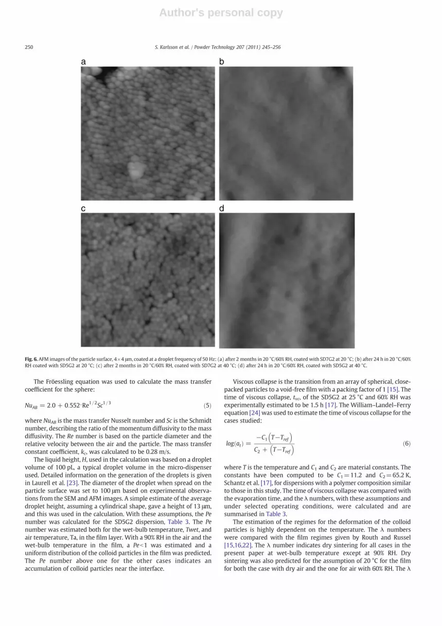
To study the influence of the glass transition temperature, Tg, twosimilar dispersions with different Tg were used. The differences in thedegree of inter-particle coalescence for the dispersion at 20 °C werefoundwith AFM. The glass beads were coated in the SPC device, whichhas a fast drying rate. As expected, the surface was smoother for thedispersionwith the lower Tg, SD5G2, than for SD7G2, Fig. 6(a) and (b).The figure demonstrates the influence of coating temperature oncolloid particle coalescence and in relation to the glass transitiontemperature. Particle deformation and further inter-diffusion acrossparticle surfaces occur at temperatures above Tg (SD5G2) since themodulus is drastically reduced and viscous flow is possible. For thehard and glassy particles of SD7G2, on the other hand, the sphericalparticle integrity remains in a frozen state well below Tg.
The SEM images show small cracks in the SD7G2 coating at 20 °Cbut no cracks are visible in the coating at 40 °C, Fig. 7. The SEM imagesshow no cracks on any of the samples with the SD5G2 coating.However, cracks were observed for the cases with coating tempera-tures below Tg. Crack formation in films was discussed by Lee andRouth [18]. Cracks will occur resulting from the capillary pressure asthe film dries. At lower temperatures with rigid particles the stresscan relax by film fracture. In accordance with the observations inFig. 7, the crack spacing increases with increasing temperature andwell above Tg no cracks appear since relaxation can take place throughparticle deformation.
3.3. Influences of moisture content and spray rate
A higher moisture content in the suspended air decreases thedrying rate and influences the film formation. Although the orderingof colloid particles was studied in the AFM image, no variation wasobserved in the samples with coating at different moisture contents.More experiments must be conducted to study the statistical orderingof the colloid particles.
The droplet frequency was doubled to observe the influence of thespray rate. The original droplets were not distinguishable in the SEMimages of particles coated at the high droplet frequency (Fig. 8).
4. Model development of coating at single-particle level
A coating layer is built up of droplets deposited, spread and driedon the particle surface. A model predicting the surface structure of acoated particle under specified process conditions must include thespreading and the drying of single droplets. The conditions in afluidised bed were central to the model development. Mechanismsthat must be taken into account in the drying of a single droplet, andthe drying of single droplets coupled to the continuous spraying ofdroplets on the particle surface, are discussed below. The modeldeveloped was used to understand how selected coating parametersinfluence the coating structure.
It will be shown that, for the experimental conditions used, thedroplets spread to the equilibrium angle without splashing, and thatthe drying during the spreading process can be disregarded. It is also
Table 2Cases studied.
Case Coating Temperature(°C)
RH(%)
Frequency(Hz)
1 SD5G2 20 0 502 SD5G2 40 0 503 SD7G2 20 0 504 SD7G2 40 0 505 SD7G2 20 0 1006 SD7G2 20 60 50
Fig. 4. SEM images of particles coated with SD5G2: (a) the first droplets deposited onthe surface; (b) the surface is almost covered with coating.
248 S. Karlsson et al. / Powder Technology 207 (2011) 245–256

Author's personal copy
shown that the colloid particles accumulate at the interface betweenthe liquid and the air; however, the formation of skin was notexpected for the operating conditions here. The dominating dryingmechanism was found to be external convection.
4.1. Mechanism evaluation
The model of single-particle coating deals separately with thespreading and drying. The spreading time was assumed to be muchfaster than the drying of one droplet, which is why the drying for theduration of the spreading was disregarded. The spreading time isestimated, according to experiments in the literature, to be in theorder of milliseconds [19,20]. This is to be comparedwith drying timesfor a single droplet, as shown later in this study, to be measurable inseconds.
The droplet impact velocity influences the spreading of the dropleton the particle surface. If the inertial forces are large compared to thecapillary and viscous forces, the droplet will break up into smallerdroplets when deposited on the particle surface, known as splashing.The Weber and Reynolds numbers are often used to predict whetherthe droplet will splash. Mundo et al. [21] proposed a correlation forthe limit to splashing in terms of the K value.
K = We1=2⋅Re0:25 ð1Þ
For a K value less than 57.7, the droplet will spread out to theequilibrium contact angle without splashing. Under some conditions,it will oscillate before it stabilizes at the equilibrium stage. The particlewas levitated in the single-particle coating, SPC, device during thecoating process. The balance of forces on the particle was used toestimate the relative velocity between the gas and the particle. Thebalance gave a gas velocity of 8.5 m/s to keep the particle levitated.The droplets were transported with the airflow; to estimate the Kvalue, the droplets were assumed to have the same velocity as the air.With data for water at 20 °C, the K value was estimated to be 35, andhence no splashing was assumed for the model.
Estimation of dimensionless numbers, λ and Pe [15,22], was usedto characterize both the drying regime and the fundamental
mechanisms that must be taken into account in the coating of thesuspended particle:
λ =time for viscous collapse
evaporation time=
η0R0 = γwa
H = Eð2Þ
Pe =water front velocity
Brownian diffusion velocity=
HEkT = 6πμR0ð Þ ð3Þ
where η0 is low shear viscosity of the polymer, R0 is the colloid particleradius, γwa is the surface tension between the air and the water, H isthe height of the dispersion, E is the evaporation rate, k is theBoltzmann constant, T is the temperature and μ is the viscosity of thesolvent.
The Pe number gives the distribution of the colloid particles duringdrying. For Pe≫1, the colloid particles tend to accumulate near theliquid–air interface, and for Pe≪1, homogeneous drying occurs withuniform colloid particle distribution through the film. Lambda, λ,indicates whether the deformation of the colloid particles will occur inwater or in air. If λb1 the colloid particles will deform in the wet film,wet sintering; if λN104, the filmwill dry before the deformation starts,dry sintering [12]. If the effects of Pe and λ are combined, we can seethat Pe≫1 and λb1, and thus the colloid particles accumulate at thesurface and sinter; the effect of this is that a skin of coalesced colloidparticles forms at the surface. The remaining water has to diffusethrough the skin, and the drying rate will obviously decrease.
The levitated particle has a drying rate in the same range as in afluidised bed, based on transfer coefficients, gas moisture content andtemperature. To estimate the drying rate, Em/s, in the constant dryingrate regime, we assumed that the air close to the surface wassaturated with water and that the suspended air was dry:
E =Mwkcρw
cws−cwbð Þ = Mwkcρw
Pws
RTs− Pwb
RTb
� �ð4Þ
where kc is the mass transfer coefficient, cws is the concentration ofwater at the surface, cwb is the concentration of water in the air flow,Mw is the water molar mass, and ρw is the water density.
Fig. 5. AFM images of droplets dried on a silica plate: (a) SD5G2, (b) SD7G2, (c) two overlapping droplets of SD5G2, and (d) SD5G2 2-D profile.
249S. Karlsson et al. / Powder Technology 207 (2011) 245–256
Author's personal copy
The Fröessling equation was used to calculate the mass transfercoefficient for the sphere:
NuAB = 2:0 + 0:552⋅Re1=2Sc1=3 ð5Þ
where NuAB is the mass transfer Nusselt number and Sc is the Schmidtnumber, describing the ratio of the momentum diffusivity to the massdiffusivity. The Re number is based on the particle diameter and therelative velocity between the air and the particle. The mass transferconstant coefficient, kc, was calculated to be 0.28 m/s.
The liquid height, H, used in the calculation was based on a dropletvolume of 100 pL, a typical droplet volume in the micro-dispenserused. Detailed information on the generation of the droplets is givenin Laurell et al. [23]. The diameter of the droplet when spread on theparticle surface was set to 100 μm based on experimental observa-tions from the SEM and AFM images. A simple estimate of the averagedroplet height, assuming a cylindrical shape, gave a height of 13 μm,and this was used in the calculation. With these assumptions, the Penumber was calculated for the SD5G2 dispersion, Table 3. The Penumber was estimated both for the wet-bulb temperature, Twet, andair temperature, Ta, in the film layer. With a 90% RH in the air and thewet-bulb temperature in the film, a Peb1 was estimated and auniform distribution of the colloid particles in the film was predicted.The Pe number above one for the other cases indicates anaccumulation of colloid particles near the interface.
Viscous collapse is the transition from an array of spherical, close-packed particles to a void-free film with a packing factor of 1 [15]. Thetime of viscous collapse, tvc, of the SD5G2 at 25 °C and 60% RH wasexperimentally estimated to be 1.5 h [17]. The William–Landel–Ferryequation [24] was used to estimate the time of viscous collapse for thecases studied:
log atð Þ =−C1 T−Tref
� �C2 + T−Tref
� � ð6Þ
where T is the temperature and C1 and C2 are material constants. Theconstants have been computed to be C1=11.2 and C2=65.2 K,Schantz et al. [17], for dispersions with a polymer composition similarto those in this study. The time of viscous collapse was compared withthe evaporation time, and the λ numbers, with these assumptions andunder selected operating conditions, were calculated and aresummarised in Table 3.
The estimation of the regimes for the deformation of the colloidparticles is highly dependent on the temperature. The λ numberswere compared with the film regimes given by Routh and Russel[15,16,22]. The λ number indicates dry sintering for all cases in thepresent paper at wet-bulb temperature except at 90% RH. Drysintering was also predicted for the assumption of 20 °C for the filmfor both the case with dry air and the one for air with 60% RH. The λ
Fig. 6. AFM images of the particle surface, 4×4 μm, coated at a droplet frequency of 50 Hz: (a) after 2 months in 20 °C/60% RH, coated with SD7G2 at 20 °C; (b) after 24 h in 20 °C/60%RH coated with SD5G2 at 20 °C; (c) after 2 months in 20 °C/60% RH, coated with SD7G2 at 40 °C; (d) after 24 h in 20 °C/60% RH, coated with SD5G2 at 40 °C.
250 S. Karlsson et al. / Powder Technology 207 (2011) 245–256

Author's personal copy
number at 40 °C indicates a capillary deformation regime. At the lowdrying rate at 90% RH, the λ number indicates a receding water frontin the film for both the assumption of wet-bulb temperature and theair temperature of 20 °C. For the SD7G2 dispersion, with a Tg of 41 °C,
dry sintering occurs in all cases. The λ numbers indicate that no skinforms in any of the cases.
With the assumption that no skin was formed and with an initialdry content, according to experimental data, of 1 wt.%, the
Fig. 7. SEM images of particle surfaces coated at a droplet frequency of 50 Hz: (a)–(b) SD7G2 at 20 °C; (c)–(d) SD7G2 at 40 °C; (e)–(f) SD5G2 at 20 °C.
251S. Karlsson et al. / Powder Technology 207 (2011) 245–256

Author's personal copy
evaporation rate is essentially governed by external convection asdiscussed later. According to the estimation of the λ number, we havedry sintering in most of the cases studied, which means that theremaining water evaporates before the particles start to deform.During drying, the water front moves from the surface between thefilm and the air through the film; the film is dry when all of the waterat the surface of the inert core particle has evaporated. The transportof water through the dry part of the film takes place by diffusion,while that from the surface between the film and the surrounding airis by convection. Themolar flux of water, depending on both diffusionand convection, is described by the equation:
Nw =pws = Ts−pwb = Tbð Þ
R 1kc
+ lDeff
� � ð7Þ
where l is the dry height of the film, increasing from zero to thethickness of the film, and Deff is the effective diffusion of waterthrough the dry film.
Using data from Table 4 the resistance to mass transfer byconvection was calculated to be 3.6 s/m. It is difficult to estimate Deff .Using a diffusion length of 500 nm (conservative), a value of Deff, of1.4·10−7 m2/s (compare with DAB, of 2.56·10−5 m2/s) gives diffu-sion and convection resistances of the same order. In the following,the diffusion resistance is neglected and the model is thus simplified.
The time for drying of the remaining water in the film wasestimated with the expression of mass transfer by convection andcompensation for the dry area to be 0.1 s. The area of the dry part ofthe particle was estimated by assuming that the minimum liquidheight on the particle surface was the average height for a droplet atequilibrium. The time for drying of the last water in the film should becompared with the drying of a droplet to a dry content of 60 wt.% in6.9 s. It should be noted that the surface temperature Ts is equal to thewet-bulb temperature, Twet.
To summarize the previous discussion, the evaluation usingdimensionless numbers showed that the droplet spreads out toequilibrium angle, and the drying during the spreading can bedisregarded. Colloid particles accumulate at the interface to the air.Since the colloid particles accumulated at the interface do not deformand build a skin on the surface, the vertical distribution of colloidparticles can be disregarded. The drying time of the last water, whenthe colloid particles have formed a packed bed with a 60 wt.% drycontent, was estimated to be 1.4% of the total drying time. It should benoted that the model breaks down in this range.
4.2. Drying of a single droplet at a constant drying rate, with lateraltransport
A model was developed of the droplet drying at a constant dryingrate. The transport of colloidal particles is independent of concentra-tion in this first drying range [9,10]. The experimental studies of singledroplets showed rings formed of colloid particles on the coatedparticle surface, which means that the lateral transport must beincluded in the model to describe the distribution of the colloidparticles. A model for single droplet deposition, spreading and dryingincluding lateral transport was developed.
In this study we adopted the constant diameter approach tosimulate the ring formation. To be able to track the lateral flow, wediscretized the droplet over the radius and formulated a mass balanceover a small volume element, see Fig. 9. As the droplets in the studywere small, the shapes of the droplets were assumed to be sphericalcaps. The height profile for a spherical cap with a centre height ofh(0,t) and a radius, R, is
h r; tð Þ =ffiffiffiffiffiffiffiffiffiffiffiffiffiffiffiffiffiffiffiffiffiffiffiffiffiffiffiffiffiffiffiffiffiffiffiffiffiffiffiffiffiffiffiffiffih 0; tð Þ2 + R2
2h 0; tð Þ
" #2
−r2
vuut −R2−h 0; tð Þ22h 0; tð Þ : ð8Þ
Table 3Pe number under selected operating conditions for dispersion SD5G2.
Ta Twet RH ETwet ETa PeTwet PeTa tvc,Twet tvc,Ta λTwet λTa
[°C] [°C] [%] [m/s] [m/s] [−] [−] [s] [s] [−] [−]
20 5.6 0 2.0·10−6 4.8·10−6 13.0 21.0 2.7·108 4.6·104 4.2·107 1.7·104
40 14.0 0 3.4·10−6 1.4·10−5 17.0 37.0 1.0·106 4.3·101 2.6·105 4.8·101
20 15.2 60 7.3·10−7 1.9·10−6 3.6 8.2 5.2·105 4.6·104 2.9·104 6.8·103
20 18.9 90 2.1·10−7 4.8·10−7 0.9 2.1 7.7·104 4.6·104 1.2·103 1.7·103
Fig. 8. SEM images of a particle coated at 20 °C with SD7G2 at a droplet frequency of 100 Hz.
252 S. Karlsson et al. / Powder Technology 207 (2011) 245–256
Author's personal copy
The mass balance for a volume element, Vi, is
ρdVi
dt= −SiNwMw + mIn−mOut ð9Þ
where Nw is the molar flux of water from the volume element to theair, and Mw is the molar mass of water; mIn and mOut are the lateralflow in and out of the volume element in kg/s.
The mass balance of the dispersed material for a volume element,Vi, is
ρdxiVi
dt= mIn⋅xi−1−mOut⋅xi ð10Þ
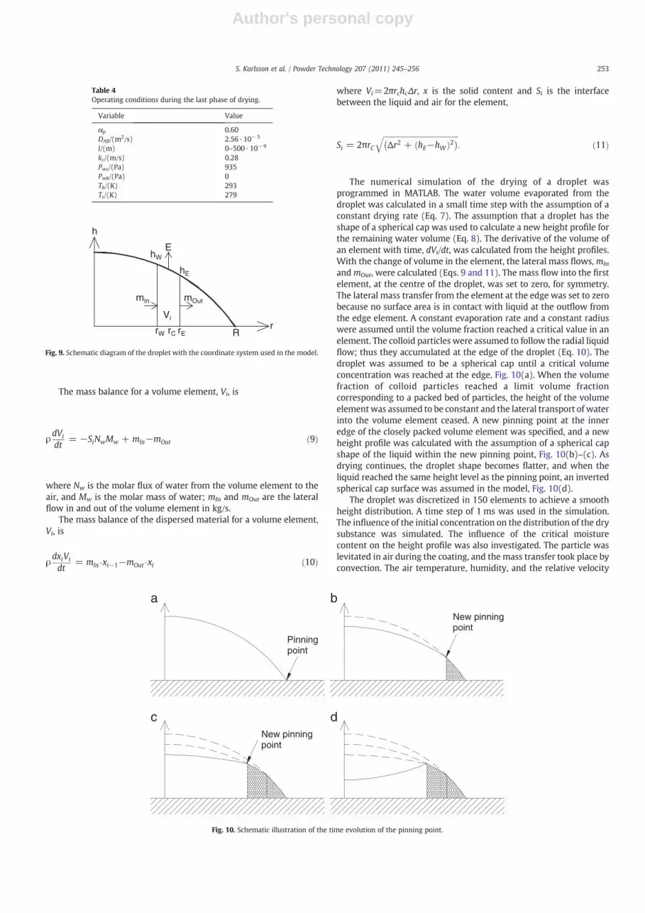
where Vi=2πrchcΔr, x is the solid content and Si is the interfacebetween the liquid and air for the element,
Si = 2πrCffiffiffiffiffiffiffiffiffiffiffiffiffiffiffiffiffiffiffiffiffiffiffiffiffiffiffiffiffiffiffiffiffiffiffiffiffiffiffiffiffiffiΔr2 + hE−hWð Þ2� �q
: ð11Þ
The numerical simulation of the drying of a droplet wasprogrammed in MATLAB. The water volume evaporated from thedroplet was calculated in a small time step with the assumption of aconstant drying rate (Eq. 7). The assumption that a droplet has theshape of a spherical cap was used to calculate a new height profile forthe remaining water volume (Eq. 8). The derivative of the volume ofan element with time, dVi/dt, was calculated from the height profiles.With the change of volume in the element, the lateral mass flows,mIn
andmOut, were calculated (Eqs. 9 and 11). The mass flow into the firstelement, at the centre of the droplet, was set to zero, for symmetry.The lateral mass transfer from the element at the edge was set to zerobecause no surface area is in contact with liquid at the outflow fromthe edge element. A constant evaporation rate and a constant radiuswere assumed until the volume fraction reached a critical value in anelement. The colloid particles were assumed to follow the radial liquidflow; thus they accumulated at the edge of the droplet (Eq. 10). Thedroplet was assumed to be a spherical cap until a critical volumeconcentration was reached at the edge, Fig. 10(a). When the volumefraction of colloid particles reached a limit volume fractioncorresponding to a packed bed of particles, the height of the volumeelementwas assumed to be constant and the lateral transport of waterinto the volume element ceased. A new pinning point at the inneredge of the closely packed volume element was specified, and a newheight profile was calculated with the assumption of a spherical capshape of the liquid within the new pinning point, Fig. 10(b)–(c). Asdrying continues, the droplet shape becomes flatter, and when theliquid reached the same height level as the pinning point, an invertedspherical cap surface was assumed in the model, Fig. 10(d).
The droplet was discretized in 150 elements to achieve a smoothheight distribution. A time step of 1 ms was used in the simulation.The influence of the initial concentration on the distribution of the drysubstance was simulated. The influence of the critical moisturecontent on the height profile was also investigated. The particle waslevitated in air during the coating, and the mass transfer took place byconvection. The air temperature, humidity, and the relative velocity
h
R
hW
hE
r
mIn mOut
Vi
E
rW rErC
Fig. 9. Schematic diagram of the droplet with the coordinate system used in the model.
Table 4Operating conditions during the last phase of drying.
Variable Value
αp 0.60DAB/(m2/s) 2.56·10−5
l/(m) 0–500·10−9
kc/(m/s) 0.28Pws/(Pa) 935Pwb/(Pa) 0Tb/(K) 293Ts/(K) 279
Pinningpoint
New pinningpoint
New pinningpoint
b
c d
a
Fig. 10. Schematic illustration of the time evolution of the pinning point.
253S. Karlsson et al. / Powder Technology 207 (2011) 245–256
Author's personal copy
between the particle and the air in the fluidised state were taken intoaccount when calculating the evaporation rate.
4.3. Single-particle level
The coating on a single particle can be built up of single drieddroplets on the surface, provided the drying rate of the droplets is fastin relation to the frequency of their deposition on the particle surface.The other extreme is when the droplets are deposited on the particlesurface rapidly in relation to the drying rate; the wet droplets arespread over the particle surface and there is no edge effect. Toillustrate the link between the drying and spray rates and theroughness of the coating, a simplified model of droplets deposited ona particle surface was developed. In the model, the droplets' positionson the particle were random. The lateral transport during drying, andassociated ring formation, was disregarded. The deposited dropletwas assumed to be a cylinder with a uniform distribution of the drysubstance during drying.
The model was programmed in MATLAB. A matrix of 161×161elements represented the particle surface. The simulation dealsseparately with the spreading and drying. The spreading of thedroplet, as in the single droplet model, was assumed to be rapid inrelation to the drying. The low initial dry content implies that theconstant rate period, when the surface was wet, dominates; thus thefalling rate period is not included in the model. After the spreading,the droplet diameter was set to constant, provided no other droplethits the same spot before the droplet has dried. If a droplet hits asurface that is already wet, the droplet spreads over the wet surface.
5. Model results and discussion
5.1. The single droplet model
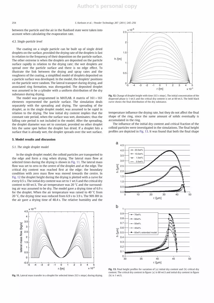
In the single droplet model, the colloid particles are transported tothe edge and form a ring when drying. The lateral mass flow atselected times during the drying is shown in Fig. 11. The lateral massflow was set to zero in the centre of the droplet and at the edge. Thecritical dry content was reached first at the edge; the boundarycondition with zero mass flow was moved towards the centre. InFig. 12 the droplet height during the drying is plotted with a curve forevery 0.5 s. The initial dry contentwas set to 1 wt.% and the critical drycontent to 60 wt.%. The air temperature was 20 °C and the surround-ing air was assumed to be dry. The model gave a drying time of 6.9 sfor the droplet. When the air temperature was raised to 40 °C from20 °C, the drying time was reduced from 6.9 s to 3.9 s. The 90% RH inthe air gave a drying time of 48.4 s. The relative humidity and the
temperature influence the drying rate, but they do not affect the finalshape of the ring, since the same amount of solids eventually isaccumulated in the ring.
The influence of the initial dry content and critical fraction of thecolloid particles were investigated in the simulations. The final heightprofiles are depicted in Fig. 13. It was found that both the final shape
-5 -4 -3 -2 -1 0 1 2 3 4 5x 10⁻⁵
-0.5
0
0.5
1
1.5
2
2.5
3
3.5
4
4.5x 10⁻¹²
r /[m]
late
ral m
ass
flow
/[kg
/s]
Fig. 11. Lateral mass transfer in a droplet for selected times (0.5 s steps) during drying.
-5 -4 -3 -2 -1 0 1 2 3 4 5
x 10-5
0
0.5
1
1.5
2
2.5x 10⁻⁵
r /[m]
h /[m]
Fig. 12. Change of droplet height with time (0.5 s steps). The initial concentration of thedispersed phase is 1 wt.% and the critical dry content is set at 60 wt.%. The bold blackcurve shows the final distribution of the dry substance.
a
b
0.0
0.5
1.0
1.5
2.0
2.5
3.0
3.5
4.0
4.5
0 10 20 30 40 50r /[µm]
h /[µ
m]
20.0wt%
10.0wt%
1.0wt%
0.5wt%
0
0.1
0.2
0.3
0.4
0.5
0.6
0.7
0.8
0.9
1
30 35 40 45 50
r /[µm]
h /[µ
m]
70wt%
60wt%
50wt%
40wt%
60wt% extended model
Fig. 13. Final height profiles for variation of (a) initial dry content and (b) critical drycontent. The critical dry content in figure (a) is 60 wt.% and initial dry content in figure(b) is 1 wt.%.
254 S. Karlsson et al. / Powder Technology 207 (2011) 245–256

Author's personal copy
and the height of the ring were influenced by the initial dry content,Fig. 13(a).
Higher initial dry contents result in higher rings since more solidmaterial is present. The ring will be more extended since the edge ofthe ring is more rapidly saturated causing more material to be “leftbehind”.
The ring height increased with increased critical dry substance,Fig. 13(b). A higher value of the critical dry substance allowsmore drysubstance to be transported to the ring. The height of the simulatedring, with 1 wt.% initial dry content, is of the same order of magnitudeas the experimental height obtained in the AFM measurements.
The assumption of zero mass flux at the point of particle closepacking may be criticized and was thus relaxed for comparison. Anexample with critical moisture content at 60 wt.% is given in Fig. 13(b). The results show a higher and steeper ring but the influences ofthe main parameters are qualitatively similar. A non zero flux at thecritical concentration means that particle transport will increase tothe layer next to the saturated one giving a higher and steeper ring.
5.2. Simulation of coating at the single-particle level
To simulate the coating of a single particle, the initial dry contentwas set to 0.5 wt.%. The influences of temperature, relative humidityof the air, and droplet frequency were investigated. The results ofsimulations of 3000 droplets, i.e. constant total mass of colloids andwater, at four sets of operating conditions are presented in Fig. 14.This is a simple multi-droplet model (e.g. no ring formation) and thestructure is simply dependent if previous drops have dried or not. Ifnot a smoothing of the surface will occur. Thus higher spray rate orlower drying rate will give a smoother surface.
A comparison of Fig. 14(a) and (b) shows that the higher spray rateindeed gives a smoother surface. The model may be used to predictthe spray rate at which a continuous film will form. The relativehumidity and the temperature in the air can also be used to influencethe surface structure, Fig. 14(c) and (d).
6. Conclusions
Levitated single particles were coated with a water-based latexdispersion under specified operating conditions. The coating abovethe glass transition temperature, Tg, gave a smoother surface thanbelow Tg. Cracks were observed in the layer for coating below Tg. Theexperimental results showed rings of latex colloid particles on thesurface. No ring pattern (but surface structure) was observed at a highspray rate, 100 Hz.
Mechanism evaluation, using dimensionless numbers, showedthat a droplet will spread to the equilibrium angle without splashingand that the latex particles accumulate at the interface between theliquid and the air under fluidized conditions. A model of the drying ofa single droplet at the particle surface was developed to describe theexperimental results of rings. The simulation of the shape and heightof the dried droplet agrees well with the experimental results. Thering height and shape are related to the initial dry content of thecoating liquid. A simple multi-droplet model of single-particle coatingmay be used to predict the rate of spray at which a continuous filmwill form. To make a more accurate model, it would be interesting tostudy the rotation rate of a particle in the spray zone and to use themeasured particle dynamics to predict the droplet position. It wouldalso be interesting to include the lateral transport in the model.
Fig. 14. Simulations of the distribution of dry substance after spreading and drying of 3000 droplets, 1 pixel=13.2 μm: (a) 50 Hz, 20 °C, 0% RH; (b) 100 Hz, 20 °C, 0% RH; (c) 50 Hz,20 °C, 60% RH; and (d) 50 Hz, 40 °C, 0% RH.
255S. Karlsson et al. / Powder Technology 207 (2011) 245–256
Author's personal copy
The results obtained in this study should be relevant for particlecoating in fluidised beds at real process conditions with highconvective mass transfer rates.
NomenclatureaT reduced variables shift factorc concentration, mol/m3
D diameter, mDAB diffusion coefficient, m2/sDeff effective diffusion coefficient, m2/sE evaporation rate, m/sh height of droplet, mH liquid height, mK limit to splashing, K=We1/2·Re0.25
k Boltzmann constant, J/Kkc mass transfer coefficient, m/sl dry height of the film, mmIn lateral mass flow into a volume element, kg/smOut lateral mass flow from a volume element, kg/sM molar mass, kg/molN molar flux, mol/(m2 s)NuAB Nusselt number, NuAB=kcDp/DAB
p pressure, PaPe Peclet number, [water front velocity]/[Brownian diffusion
velocity]r radial distance, mR molar gas constant, J/(mol K)R radius, mRe Reynolds number, Re=ρuD/μRH relative humidityS surface area, m2
Sc Schmidt number, Sc=μ/(ρfDAB)t time, sT temperature, KTg glass transition temperature, Ku droplet velocity, m/sV volume, m3
We Weber number, We=ρu2D/γx solid content
Greek Lettersα volume fractionγ surface tension, N/mη0 low shear viscosity of the polymer, Ns/m2
λ [time for viscous collapse]/[evaporation time]μ viscosity, Pasρ density, kg/m3
Subscripts0 colloid particlea airb bulkC centred dropletE Easti volume elementp particles surfacevc viscous collapsew waterwet wet-bulbW West
Acknowledgements
We would like to thank Dr. Mark Nicholas at AstraZeneca for veryhelpful discussions about AFM. Financial support from the SwedishFoundation for Strategic Research (SSF) within the Centre forChemical Process Design and Control (CPDC) and the support withthe experimental set-up from AstraZeneca are gratefullyacknowledged.
References
[1] A. Laicher, C.A. Lorck, P.C. Grunenberg, H. Klemm, F. Stanislaus, Aqueous coating ofpellets to sustained-release dosage forms in a fluid-bed coater. Influence ofproduct temperature and polymer concentration on in vitro release, Pharm. Ind.55 (12) (1993) 1113–1116.
[2] H. Kage, T. Takahashi, T. Yoshida, H. Ogura, Y. Matsuno, Coating efficiency of seedparticles in a fluidized bed by atomization of a powder suspension, PowderTechnol. 86 (3) (1996) 243–250.
[3] K. Saleh, D. Steinmetz, M. Hemati, Experimental study and modeling of fluidizedbed coating and agglomeration, Powder Technol. 130 (1–3) (2003) 116–123.
[4] M. Hemati, R. Cherif, K. Saleh, V. Pont, Fluidized bed coating and granulation:influence of process-related variables and physicochemical properties on thegrowth kinetics, Powder Technol. 130 (1–3) (2003) 18–34.
[5] K.C. Link, E.-U. Schlünder, Fluidized bed spray granulation and film coating. A newmethod for investigation of coating process on a single sphere, Drying Technol. 15(6–8) (1997) 1827–1843.
[6] R.C. Panda, J. Zank, H. Martin, Experimental investigation of droplet deposition ona single particle, Chem. Eng. J. 83 (1) (2001) 1–5.
[7] D. Strom, S. Karlsson, S. Folestad, I. Niklasson Bjorn, T. Laurell, J. Nilsson, A.Rasmuson, A new device for coating single particles under controlled conditions,Chem. Eng. Sci. 60 (16) (2005) 4647–4653.
[8] S. Kiil, Drying of latex films and coatings: reconsidering the fundamentalmechanisms, Prog. Org. Coat. 57 (3) (2006) 236–250.
[9] J. Vanderhoff, E. Bradford, W. Carrington, The transport of water through latexfilms, J. Polym. Sci Symp 41 (1973) 155–174.
[10] S. Erkselius, Film Formation from Dispersions, Preparation and Mechanisms,Department of Polymer Science and Engineering, Ph.D. Thesis, Lund University,Lund, Sweden, (2006).
[11] R.D. Deegan, O. Bakajin, T.F. Dupont, G. Huber, S.R. Nagel, T.A. Witten, Capillaryflow as the cause of ring stains from dried liquid drops, Nature 389 (6653) (1997)827–829.
[12] A.F. Routh, W.B. Russel, Horizontal drying fronts during solvent evaporation fromlatex films, AIChE J. 44 (9) (1998) 2088–2098.
[13] F. Parisse, C. Allain, Shape changes of colloidal suspension droplets during drying,J. Phys. II 6 (1996) 1111–1119.
[14] R.D. Deegan, O. Bakajin, T.F. Dupont, G. Huber, S.R. Nagel, T.A. Witten, Contact linedeposits in an evaporating drop, Phys. Rev. E 62 (1) (2000) 756.
[15] A.F. Routh, W.B. Russel, A process model for latex film formation: limiting regimesfor individual driving forces, Langmuir 15 (1999) 7762–7773.
[16] A.F. Routh, W.B. Russel, A process model for latex film formation: limiting regimesfor individual driving forces. Additions and corrections, Langmuir 17 (23) (2001)7446–7447.
[17] S. Schantz, H.T. Carlsson, T. Andersson, S. Erkselius, A. Larsson, O.J. Karlsson, Poly(methyl methacrylate-co-ethyl acrylate) latex particles with poly(ethyleneglycol) grafts: structure and film formation, Langmuir 23 (7) (2007) 3590–3602.
[18] W.P. Lee, A.F. Routh, Why do drying films crack? Langmuir 20 (23) (2004)9885–9888.
[19] Y. Gu, D. Li, Liquid drop spreading on solid surfaces at low impact speeds, ColloidsSurf., A 163 (2–3) (2000) 239–245.
[20] H. Park, W.W. Carr, J. Zhu, J.F. Morris, Single drop impaction on a solid surface,AIChE J. 49 (2003) 2461–2471.
[21] C. Mundo, M. Sommerfeld, C. Tropea, Droplet-wall collisions: experimentalstudies of the deformation and breakup process, Int. J. Multiph. Flow 21 (2)(1995) 151–173.
[22] A.F. Routh, W.B. Russel, Deformation mechanisms during latex film formation:experimental evidence, Ind. Eng. Chem. Res. 40 (20) (2001) 4302–4308.
[23] T. Laurell, L. Wallman, J. Nilsson, Design and development of a siliconmicrofabricated flow-through dispenser for on-line picolitre sample handling, J.Micromech. Microeng. 9 (1999) 369–376.
[24] M.L. Williams, R.F. Landel, J.D. Ferry, The temperature dependence of relaxationmechanisms in amorphous polymers and other glass-forming liquids, J. Am.Chem. Soc. 77 (1955) 3701–3707.
256 S. Karlsson et al. / Powder Technology 207 (2011) 245–256