characterisation of the spray cooling heat transfer involved in a high pressure die casting process
TRANSCRIPT
Int. J. Therm. Sci. (2000) 39, 582–591 2000 Éditions scientifiques et médicales Elsevier SAS. All rights reservedS1290-0729(00)00207-6/FLA
Characterisation of the spray cooling heat transferinvolved in a high pressure die casting process
Guang Wei Liu a*, Yosry Sadeik Morsi a, Brian Robert Clayton b
a Center for Modelling and Process Analysis, School of Engineering and Science, Swinburne University of Technology, John Street, Hawthorn,P.O. Box 218, Victoria 3122, Australia
b School of Mechanical, Materials, Manufacturing Engineering and Management, University of Nottingham, University Park,Nottingham, NG7 2RD, UK
(Received 22 June 1999, accepted 4 October 1999)
Abstract —A systematic experimental study was conducted to examine the heat transfer characteristics from the hot die surfaceto the water spray involved in high pressure die casting processes. Temperature and heat flux measurements were made locally inthe spray field using a heater made from die material H-13 steel and with a surface diameter of 10 mm. The spray cooling curvewas determined in the nucleate boiling, critical heat flux, as well as the transition boiling regimes. The hydrodynamic parameters ofthe spray such as droplet diameters, droplet velocities, and volumetric spray flux were also measured at the position in the sprayfield identical to that of the test piece. Droplet size and velocity distribution were measured using a PDA system. A new empiricalcorrelation was developed to relate the spray cooling heat flux to the spray hydrodynamic parameters such as liquid volumetric flux,droplet size, and droplet velocity in all heat transfer regimes. The agreement between experimental data and predicted results issatisfactorily good. 2000 Éditions scientifiques et médicales Elsevier SAS
spray cooling / surface heat flux / droplet velocity / droplet diameter / high pressure die casting
Nomenclature
A1,A2, . . . ,A5 areas . . . . . . . . . . . . . m2
A,B,C,D coefficients in equation (5)
Cpl liquid specific heat . . . . . . J·kg−1·K−1
D32 Sauter mean diameter . . . . md0, d1, . . . , d5 droplet Sauter mean diameter
at locations 0 to 5 shown infigure 4 . . . . . . . . . . . . m
d cross-surface Sauter meandiameter . . . . . . . . . . . m
hfg latent heat of vaporization . . J·kg−1
Q volumetric spray flux . . . . m3·s−1
q surface heat flux . . . . . . . Wq∗ dimensionless surface heat fluxRA ratio of droplet cross-surface
mean velocity and thevolumetric spray flux . . . . m−2
Re Reynolds number
* Correspondence and [email protected]
T ∗ dimensionless surfacetemperature
U0,U1, . . . ,U5 droplet velocity at locations0 to 5 shown infigure 4 . . . m·s−1
u cross-surface mean dropletvelocity . . . . . . . . . . . . m·s−1
We Weber number
Greek symbols
µ viscosity . . . . . . . . . . . Pa·sρ density . . . . . . . . . . . . kg·m−3
σ surface tension . . . . . . . . N·m−1
1. INTRODUCTION
Casting is the most economic industrial process usedto transform liquid metals into near net shape compo-nents. Die casting is a commonly used technique in mod-ern foundry industries in which the liquid metal is pouredinto the metal mould or squeezed into the mould underpressure. When a part comes out, it has the desired shape
582
Characterisation of the spray cooling heat transfer involved in a high pressure die casting process
for a particular application. In order to produce high qual-ity castings, it is essential to understand the flow and heattransfer phenomena involved in the casting process.
There is a considerable body of open literature dis-cussing the numerical modelling of the physical processesinvolved in casting processes. Most of it, however, isfocused on the filling and solidification of liquid metalin the die. The modelling of these processes is nor-mally based on finite difference or finite element meth-ods and has reached a state of maturity. Currently thereare many commercial software packages available in themarket worldwide, such as MAVIS and DIANA (UK),SOLSTAR (USA), MAGMAsoft (Germany), Simulor(France) and Stefan Software (Japan). However, as far asspray cooling is concerned, none of these packages incor-porate the mechanism of spray cooling.
In a high pressure die casting process, a liquid sprayis used to lubricate as well as to cool the steel die.A thorough knowledge of the spray cooling of the diewill facilitate the design and maintenance of a morethermally balanced die by the die caster, leading toimproved quality and lower manufacturing costs. Despitethe importance of die sprays in high pressure die casting,the heat removal characteristics of the die sprays arenot well understood. As a result, there is no computersoftware available in the market which incorporates thetotal simulation of the spray cooling of the die. The workreported in this paper is the first step to rectify this.
A spray atomises bulk liquid into fine drops by eithersupplying liquid at high pressure through a small orifice(plain orifice spray) or by assisting liquid breakup usinghigh pressure air (air-atomised spray). Significant heattransfer occurs when droplets produced by a liquid spraysubsequently impact a hot surface.
As a metallic block is cooled by spray, its surface mayexperience four different heat transfer regimes: a filmboiling regime, a transition boiling regime, a nucleateboiling regime and single-phase liquid cooling. The filmboiling regime is characterised by an insulating vapourblanket on the surface which prevents the liquid frommaking direct contact with the surface and results in slowcooling. Once the temperature decreases below this pointof minimum heat flux (the Leidenfrost point), the vapourblanket begins to collapse which ensures partial wettingof the surface. This transition boiling regime is markedby a significant increase in the surface heat flux owing tointense boiling, thus causing a rapid decrease in the sur-face temperature. The maximum heat flux occurs at thepoint of critical heat flux (CHF) where the vapour layerbegins to vanish, causing the cooling rate to become amaximum. In the nucleate boiling regime, the entire sur-
face experiences liquid contact and vigorous bubble pro-duction, keeping cooling rates fairly high. Boiling com-pletely subsides in the single-phase cooling regime andthe relatively low heat transfer rate is the result of con-vection. There has been no comprehensive model estab-lished for the heat transfer process during spray coolingbecause of the complexity of the mechanisms involved.Nevertheless, after conducting a review of literature onheat transfer to sprays in the film boiling regime, Brima-combe et al. [1] concluded that the volumetric spray fluxhas the greatest influence on the heat transfer coefficient.
Mudawar and Valentine [2] explored methods of de-termining the heat transfer coefficient of spray coolingto aluminium blocks in transition boiling, nucleate boil-ing, and single-phase cooling regimes using a plain ori-fice spray. They determined that the spray heat flux hadto be based on the spray hydrodynamic parameters ad-jacent to the impingement location at the heater surface.Their heat transfer correlations were based on measure-ments made at the geometric centre of each spray. Deit-ers and Mudawar [3], and Mudawar and Deiters [4] laterconcluded that these correlations were valid at other loca-tions within the spray field when the spray hydrodynamicparameters were determined for these locations.
Klinzing et al. [5] used the spray quenching heattransfer correlations and the spatial distribution models ofthe spray hydrodynamic parameters developed by Deitersand Mudawar [3, 6] to simulate the spray quenching of athin, stationary rectangular Aluminium 1100 plate usingthe commercial finite element software package ANSYS.Subsequently, Mudawar and Deiters [4] predicted thetemperature history of an Aluminium 1100 block whichwas sprayed over one surface and whose other surfaceswere well insulated.
Yang et al. [7] studied the heat transfer phenomena inthe nucleate boiling regime of spray cooling using air-driven spray nozzles and water as coolant. Flow fieldparameters such as liquid film thickness and flow ratewere used to arrive at a correlation for the Nusselt numberin the nucleate boiling regime.
The spray involved in a high pressure die castingprocess is air-atomised spray. Only a few research pro-jects directly concerned with this process have been pub-lished. Altan et al. [8] investigated how various sprayingparameters, especially the sprayed water/lubricant tem-perature and the spray pressure, affect the heat transferfrom the die. They found that: (a) the temperature of thewater in the spray tanks has little effect on the amount ofheat removed from a heated die by spraying; (b) the depthof cooling by a water spray on dies is rather small. Thedie temperature, at 25 mm from the die surface, is rela-
583
G.W. Liu et al.
tively unaffected even by a spray of duration 3 seconds;(c) with the spray parameters commonly used in the diecasting, the dies are below the Leidenfrost point, so boil-ing begins in the transition boiling regime. The criticalheat flux occurs between surface temperatures of 165◦Cand 215◦C. A quantitative relationship between the heatflux and the spray hydrodynamic parameters was not,however, established. Chhabra et al. [9], Lee et al. [10],Graff and Kallien [11] investigated experimentally the in-fluences of different parameters such as air pressure, liq-uid flux density, die surface temperature and die lubricantcomposition on the die temperature and die surface heatflux. All these researchers did not achieve a quantitativerelationship between the heat flux and the spray hydrody-namic parameters.
The aim of this paper is to examine the spray cool-ing mechanism involved in a high pressure die castingprocess using an experimental approach. The data ob-tained are then used to develop a new correlation to pre-
dict the spray heat flux quantitatively. To the authors’knowledge, this correlation will be the first quantitativeequation to predict the spray cooling heat flux involvedin a high pressure die casting process. Although other re-searchers such as Mudawar and Valentine [2] have devel-oped correlations for spray cooling that were not applica-ble to high pressure die casting process.
2. EXPERIMENTAL SETUP
The experimental setup consists of a spray system, testheater, and a PDA spray droplet velocity and diametermeasurement system.
2.1. Spray system
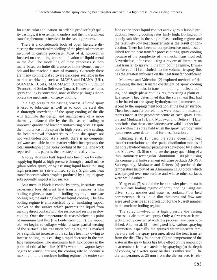
An air-atomised spray system was constructed and isshown schematically infigure 1. The spray nozzle was
Figure 1. Schematic of the spray system.
584
Characterisation of the spray cooling heat transfer involved in a high pressure die casting process
supplied by Spraying System Co. Pty Ltd. The mainair line supply was divided into two branches, oneled directly to the air inlet of the spray nozzle andthe other was used to pressurise water in the tankso that water could be supplied to the liquid inlet ofthe spray nozzle at any desired pressure. The mainair line pressure could be regulated and measured bythe air regulator and gauge. By careful regulation ofthe needle valves, the air pressure and liquid pressureto the nozzle can be adjusted independently to speci-fied values. The pressurised liquid and compressed airwere mixed internally to produce a completely atom-ised spray. Filters were also used to ensure the pu-rity of the air and liquid components to the spray noz-zle.
2.2. Test heater
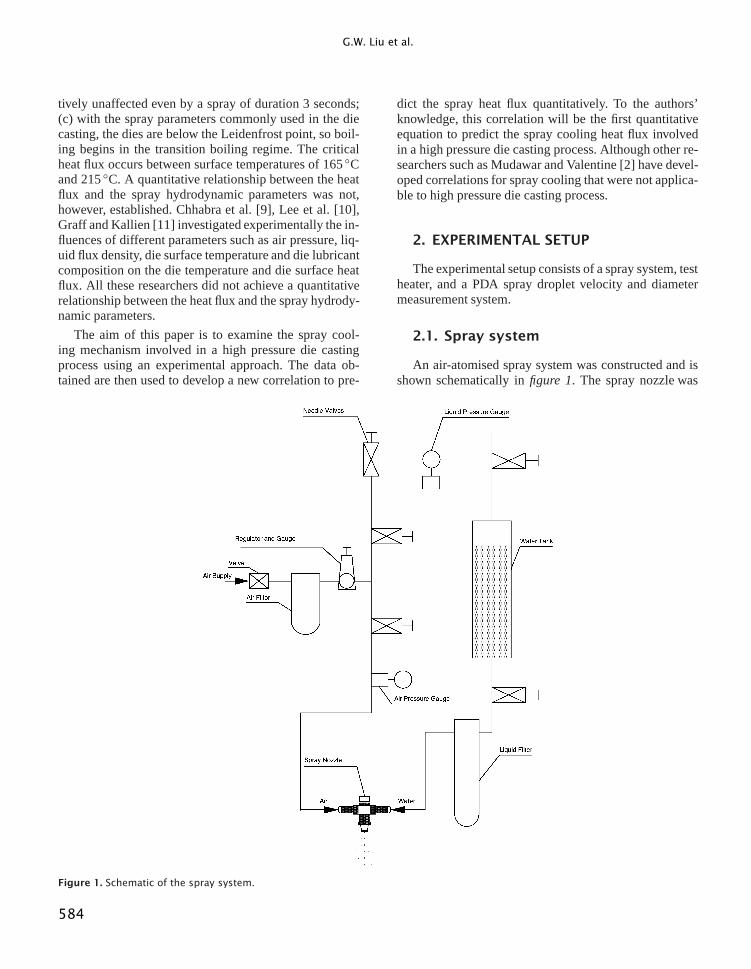
The test heater was designed to investigate the localheat flux from the test-piece to the spray cooling.Fig-ure 2shows the sectional view of the insulated test heater.In order to simulate the working conditions of a real die,the test-piece was made from H-13 steel. The tester op-erated in the range 150◦C to 350◦C which covered therange of initial die temperatures typically experienced ina die casting operation. The spray cooled surface areaof the steel test-piece was small enough (10 mm diam-eter) to ensure that the whole surface was covered by thespray field. Heat was supplied to the test-piece by three6 mm diameter cartridge heating elements which workedat a maximum temperature of 800◦C. Four high responseK-type thermocouples were embedded in the neck ofthe sample to obtain temperature differentials. The cor-responding temperature gradient obtained was then usedto determine surface temperature and an estimation ofsurface heat flux using Fourier’s law of heat conduc-tion. A PC controlled Datataker, model DT50, manufac-tured by Data Electronics, was programmed to recordthe readings of all four thermocouples every half sec-ond.
The steel test heater was thermally insulated to reduceheat losses and to ensure that heat was conducted mainlyto the spray cooled surface. The thermal insulation ma-terial used was Fibertex with a maximum service tem-perature of 650◦C and continuous service temperature of550◦C, respectively. The test heater was well sealed withsilicon sealant to prevent water from penetrating duringspray cooling.
Figure 2. Sectional view of the insulated test heater.
2.3. PDA droplet velocity and diametermeasurement
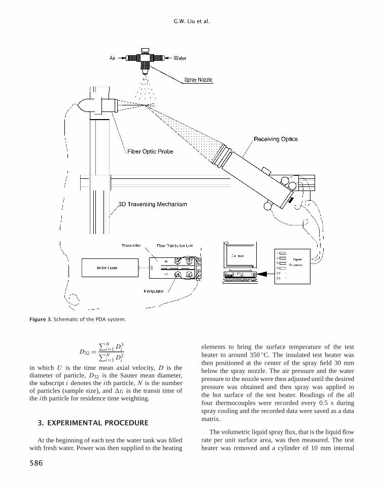
A Dantec Particle Dynamic Analyser (PDA) sys-tem [12, 13] was used to measure spray droplet size andvelocity and their distributions simultaneously.Figure 3shows the schematic of the system.
A 4W argon ion laser was used to obtain a greenbeam (wave length of 514.5 nm). The transmitting opticsconsist of a collimator, polarisation rotator, a dispersionprism, a beam splitter, a Bragg cell, a beam spacerand a fiber optic module with a 150 mm focal lengthlens. In setting up the transmitting optics, attention waspaid to such factors as mode structure, polarisation,optical path length balancing and correct beam waistpositioning in the measurement volume. A frequencyshift of 40 MHz was introduced in one of the crossinglaser beams to overcome the sign ambiguity of thevelocity measurements.
The time mean velocity and the Sauter mean diameterof the droplet were calculated using the following equa-tions:
U =∑Ni=1Ui1ti∑Ni=11ti
585
G.W. Liu et al.
Figure 3. Schematic of the PDA system.
D32=∑Ni=1D
3i∑N
i=1D2i
in which U is the time mean axial velocity,D is thediameter of particle,D32 is the Sauter mean diameter,the subscripti denotes theith particle,N is the numberof particles (sample size), and1ti is the transit time oftheith particle for residence time weighting.
3. EXPERIMENTAL PROCEDURE
At the beginning of each test the water tank was filledwith fresh water. Power was then supplied to the heating
elements to bring the surface temperature of the testheater to around 350◦C. The insulated test heater wasthen positioned at the center of the spray field 30 mmbelow the spray nozzle. The air pressure and the waterpressure to the nozzle were then adjusted until the desiredpressure was obtained and then spray was applied tothe hot surface of the test heater. Readings of the allfour thermocouples were recorded every 0.5 s duringspray cooling and the recorded data were saved as a datamatrix.
The volumetric liquid spray flux, that is the liquid flowrate per unit surface area, was then measured. The testheater was removed and a cylinder of 10 mm internal
586
Characterisation of the spray cooling heat transfer involved in a high pressure die casting process
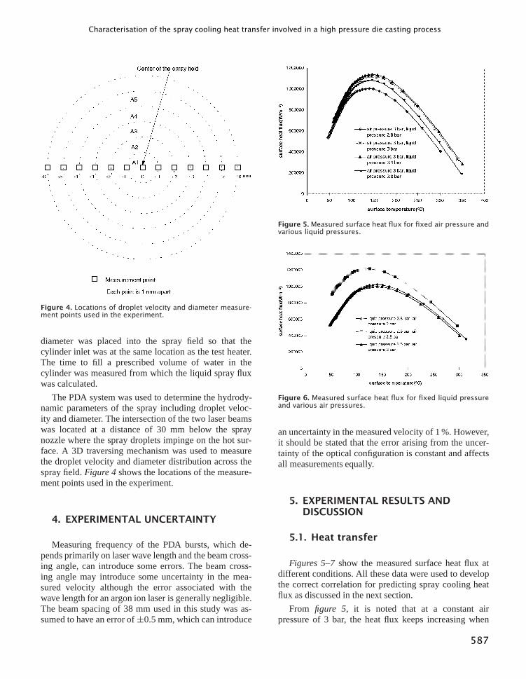
Figure 4. Locations of droplet velocity and diameter measure-ment points used in the experiment.
diameter was placed into the spray field so that thecylinder inlet was at the same location as the test heater.The time to fill a prescribed volume of water in thecylinder was measured from which the liquid spray fluxwas calculated.
The PDA system was used to determine the hydrody-namic parameters of the spray including droplet veloc-ity and diameter. The intersection of the two laser beamswas located at a distance of 30 mm below the spraynozzle where the spray droplets impinge on the hot sur-face. A 3D traversing mechanism was used to measurethe droplet velocity and diameter distribution across thespray field.Figure 4shows the locations of the measure-ment points used in the experiment.
4. EXPERIMENTAL UNCERTAINTY
Measuring frequency of the PDA bursts, which de-pends primarily on laser wave length and the beam cross-ing angle, can introduce some errors. The beam cross-ing angle may introduce some uncertainty in the mea-sured velocity although the error associated with thewave length for an argon ion laser is generally negligible.The beam spacing of 38 mm used in this study was as-sumed to have an error of±0.5 mm, which can introduce
Figure 5. Measured surface heat flux for fixed air pressure andvarious liquid pressures.
Figure 6. Measured surface heat flux for fixed liquid pressureand various air pressures.
an uncertainty in the measured velocity of 1 %. However,it should be stated that the error arising from the uncer-tainty of the optical configuration is constant and affectsall measurements equally.
5. EXPERIMENTAL RESULTS ANDDISCUSSION
5.1. Heat transfer
Figures 5–7show the measured surface heat flux atdifferent conditions. All these data were used to developthe correct correlation for predicting spray cooling heatflux as discussed in the next section.
From figure 5, it is noted that at a constant airpressure of 3 bar, the heat flux keeps increasing when
587
G.W. Liu et al.
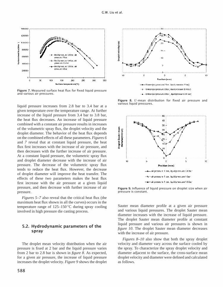
Figure 7. Measured surface heat flux for fixed liquid pressureand various air pressures.
liquid pressure increases from 2.8 bar to 3.4 bar at agiven temperature over the temperature range. At furtherincrease of the liquid pressure from 3.4 bar to 3.8 bar,the heat flux decreases. An increase of liquid pressurecombined with a constant air pressure results in increasesof the volumetric spray flux, the droplet velocity and thedroplet diameter. The behavior of the heat flux dependson the combined effects of all these parameters.Figures 6and 7 reveal that at constant liquid pressure, the heatflux first increases with the increase of air pressure, andthen decreases with the further increase of air pressure.At a constant liquid pressure, the volumetric spray fluxand droplet diameter decrease with the increase of airpressure. The decrease of the volumetric spray fluxtends to reduce the heat flux. However, the decreaseof droplet diameter will improve the heat transfer. Theeffects of these two parameters makes the heat fluxfirst increase with the air pressure at a given liquidpressure, and then decrease with further increase of airpressure.
Figures 5–7also reveal that the critical heat flux (themaximum heat flux shown in all the curves) occurs in thetemperature range of 125–150◦C during spray coolinginvolved in high pressure die casting process.
5.2. Hydrodynamic parameters of thespray
The droplet mean velocity distribution when the airpressure is fixed at 2 bar and the liquid pressure variesfrom 2 bar to 2.8 bar is shown infigure 8. As expected,for a given air pressure, the increase of liquid pressureincreases the droplet velocity.Figure 9shows the droplet
Figure 8. U -mean distribution for fixed air pressure andvarious liquid pressures.
Figure 9. Influence of liquid pressure on droplet size when airpressure is constant.
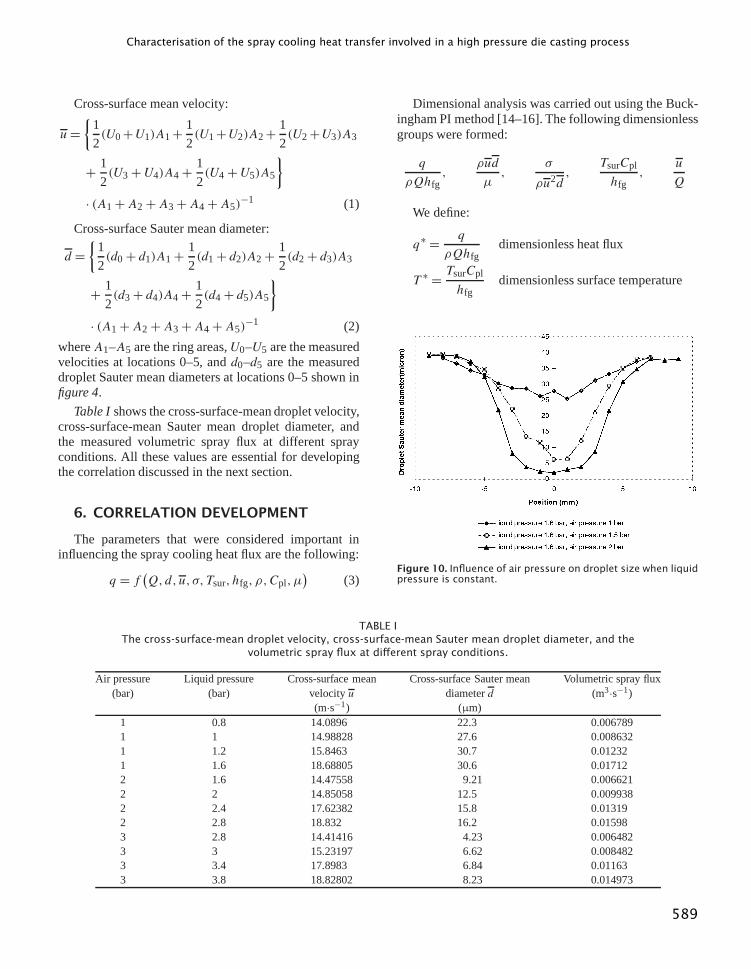
Sauter mean diameter profile at a given air pressureand various liquid pressures. The droplet Sauter meandiameter increases with the increase of liquid pressure.The droplet Sauter mean diameter profile at constantliquid pressure and various air pressures is shown infigure 10. The droplet Sauter mean diameter decreaseswith the increase of air pressure.
Figures 8–10also show that both the spray dropletvelocity and diameter vary across the surface cooled bythe spray. To characterize the spray droplet velocity anddiameter adjacent to the surface, the cross-surface meandroplet velocity and diameter were defined and calculatedas follows.
588
Characterisation of the spray cooling heat transfer involved in a high pressure die casting process
Cross-surface mean velocity:
u={
1
2(U0+U1)A1+ 1
2(U1+U2)A2+ 1
2(U2+U3)A3
+ 1
2(U3+U4)A4+ 1
2(U4+U5)A5
}· (A1+A2+A3+A4+A5)
−1 (1)
Cross-surface Sauter mean diameter:
d ={
1
2(d0+ d1)A1+ 1
2(d1+ d2)A2+ 1
2(d2+ d3)A3
+ 1
2(d3+ d4)A4+ 1
2(d4+ d5)A5
}· (A1+A2+A3+A4+A5)
−1 (2)
whereA1–A5 are the ring areas,U0–U5 are the measuredvelocities at locations 0–5, andd0–d5 are the measureddroplet Sauter mean diameters at locations 0–5 shown infigure 4.
Table Ishows the cross-surface-mean droplet velocity,cross-surface-mean Sauter mean droplet diameter, andthe measured volumetric spray flux at different sprayconditions. All these values are essential for developingthe correlation discussed in the next section.
6. CORRELATION DEVELOPMENT
The parameters that were considered important ininfluencing the spray cooling heat flux are the following:
q = f (Q,d,u,σ,Tsur, hfg, ρ,Cpl,µ)
(3)
Dimensional analysis was carried out using the Buck-ingham PI method [14–16]. The following dimensionlessgroups were formed:
q
ρQhfg,
ρud
µ,
σ
ρu2d,
TsurCpl
hfg,
u
Q
We define:
q∗ = q
ρQhfgdimensionless heat flux
T ∗ = TsurCpl
hfgdimensionless surface temperature
Figure 10. Influence of air pressure on droplet size when liquidpressure is constant.
TABLE IThe cross-surface-mean droplet velocity, cross-surface-mean Sauter mean droplet diameter, and the
volumetric spray flux at different spray conditions.
Air pressure Liquid pressure Cross-surface mean Cross-surface Sauter mean Volumetric spray flux(bar) (bar) velocityu diameterd (m3·s−1)
(m·s−1) (µm)1 0.8 14.0896 22.3 0.0067891 1 14.98828 27.6 0.0086321 1.2 15.8463 30.7 0.012321 1.6 18.68805 30.6 0.017122 1.6 14.47558 9.21 0.0066212 2 14.85058 12.5 0.0099382 2.4 17.62382 15.8 0.013192 2.8 18.832 16.2 0.015983 2.8 14.41416 4.23 0.0064823 3 15.23197 6.62 0.0084823 3.4 17.8983 6.84 0.011633 3.8 18.82802 8.23 0.014973
589
G.W. Liu et al.
Re= ρudµ
Reynolds number
We= σ
ρu2dWeber number
RA= u
Qthe ratio of the droplet velocity
and the volumetric liquid flux
Then, we have
q∗ = f (Re,We, T ∗,RA)
(4)
At each experimental case,Re, We, andRAare constant,q∗ is only a function of the dimensionless surfacetemperatureT ∗. For each test case, it was found thatquite accurate relationships betweenq∗ andT ∗ could beestablished by the following polynomial:
q∗ =AT ∗3+BT ∗2+CT ∗ +D (5)
in which each of the coefficientsA, B, C, D differs foreach test case and are clearly functions ofRe, We, andRA.
Least squares fitting ofA,B,C,D values to the valuesof Re, We, andRA for the experimental data resulted inthe following equations:
A= 10−4.05434Re1.45101We1.27899RA0.864281 (6)
B =−10−3.6164Re1.31859We1.17256RA0.915949 (7)
C = 10−3.64182Re1.21498We1.09276RA0.949317 (8)
D =−10−4.15201Re1.13977We1.03674RA0.963274 (9)
Equation (5) is the proposed correlation to predict thespray cooling heat flux involved in a high pressure diecasting process with the coefficients defined in equations(6)–(9). This correlation is capable of predicting the heatflux at all the heat transfer regimes involved in the spraycooling of a high pressure die casting process.
7. EVALUATION OF THE EMPIRICALCORRELATION
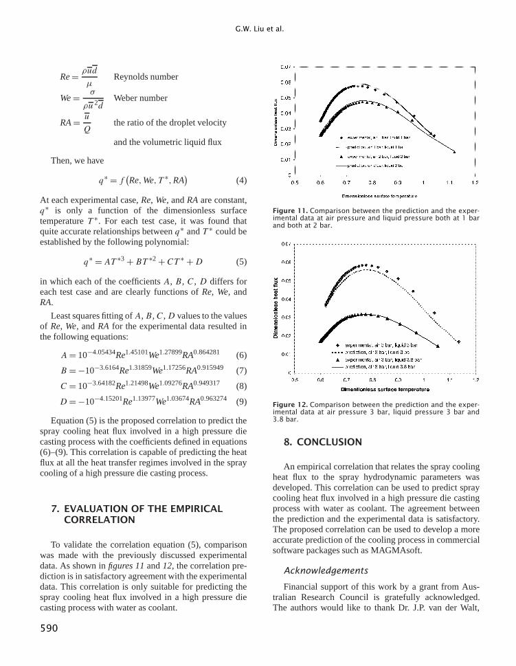
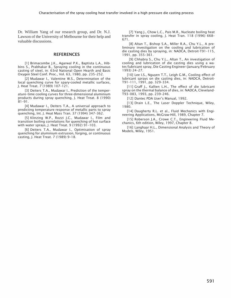
To validate the correlation equation (5), comparisonwas made with the previously discussed experimentaldata. As shown infigures 11and12, the correlation pre-diction is in satisfactory agreement with the experimentaldata. This correlation is only suitable for predicting thespray cooling heat flux involved in a high pressure diecasting process with water as coolant.
Figure 11. Comparison between the prediction and the exper-imental data at air pressure and liquid pressure both at 1 barand both at 2 bar.
Figure 12. Comparison between the prediction and the exper-imental data at air pressure 3 bar, liquid pressure 3 bar and3.8 bar.
8. CONCLUSION
An empirical correlation that relates the spray coolingheat flux to the spray hydrodynamic parameters wasdeveloped. This correlation can be used to predict spraycooling heat flux involved in a high pressure die castingprocess with water as coolant. The agreement betweenthe prediction and the experimental data is satisfactory.The proposed correlation can be used to develop a moreaccurate prediction of the cooling process in commercialsoftware packages such as MAGMAsoft.
Acknowledgements
Financial support of this work by a grant from Aus-tralian Research Council is gratefully acknowledged.The authors would like to thank Dr. J.P. van der Walt,
590
Characterisation of the spray cooling heat transfer involved in a high pressure die casting process
Dr. William Yang of our research group, and Dr. N.J.Lawson of the University of Melbourne for their help andvaluable discussions.
REFERENCES
[1] Brimacombe J.K., Agarwal P.K., Baptista L.A., Hib-bins S., Prabhakar B., Spraying cooling in the continuouscasting of steel, in: 63rd National Open Hearth and BasicOxygen Steel Conf. Proc., Vol. 63, 1980, pp. 235–252.
[2] Mudawar I., Valentine W.S., Determination of thelocal quenching curve for spary-cooled metallic surfaces,J. Heat Treat. 7 (1989) 107–121.
[3] Deiters T.A., Mudawar I., Prediction of the temper-ature–time cooling curves for three-dimensional aluminiumproducts during spray quenching, J. Heat Treat. 8 (1990)81–91.
[4] Mudawar I., Deiters T.A., A universal approach topredicting temperature response of metallic parts to sprayquenching, Int. J. Heat Mass Tran. 37 (1994) 347–362.
[5] Klinzing W.P., Rozzi J.C., Mudawar I., Film andtransition boiling correlations for quenching of hot surfacewith water sprays, J. Heat Treat. 9 (1992) 91–103.
[6] Deiters T.A., Mudawar I., Optimisation of sprayquenching for aluminium extrusion, forging, or continuouscasting, J. Heat Treat. 7 (1989) 9–18.
[7] Yang J., Chow L.C., Pais M.R., Nucleate boiling heattransfer in spray cooling, J. Heat Tran. 118 (1996) 668–671.
[8] Altan T., Bishop S.A., Miller R.A., Chu Y.L., A pre-liminary investigation on the cooling and lubrication ofdie casting dies by spraying, in: NADCA, Detroit-T91–115,1991, pp. 355–361.
[9] Chhabra S., Chu Y.L., Altan T., An investigation ofcooling and lubrication of die casting dies using a wa-ter/lubricant spray, Die Casting Engineer (January/February1993) 24–27.
[10] Lee I.S., Nguyen T.T., Leigh G.M., Cooling effect oflubricant sprays on die casting dies, in: NADCA, Detroit-T91–111, 1991, pp. 329–334.
[11] Graff J., Kallien L.H., The effect of die lubricantspray on the thermal balance of dies, in: NADCA, Cleveland-T93–083, 1993, pp. 239–246.
[12] Dantec PDA User’s Manual, 1992.[13] Drain L.E., The Laser Doppler Technique, Wiley,
1980.[14] Daugherty R.L. et al., Fluid Mechanics with Engi-
neering Applications, McGraw-Hill, 1989, Chapter 7.[15] Roberson J.A., Crowe C.T., Engineering Fluid Me-
chanics, 6th edition, Wiley, 1997, Chapter 8.[16] Langhaar H.L., Dimensional Analysis and Theory of
Models, Wiley, 1951.
591