bounds modelling and compiler optimizations for superscalar performance tuning
TRANSCRIPT

Bounds modelling and compiler optimizations for superscalarperformance tuning
Pradip Bose a,*, Sunil Kim b, Francis P. O'Connell b, William A. Ciarfella b
a IBM Corporation, T.J. Watson Research Center, PO Box 218 (route 134), Yorktown Heights, NY, USAb IBM Corporation, High-End Processor Development, Austin, TX, USA
Abstract
We consider the ¯oating point microarchitecture support in RISC superscalar processors. We brie¯y review the
fundamental performance trade-o�s in the design of such microarchitecutres. We propose a simple, yet e�ective bounds
model to deduce the ``best-case'' loop performance limits for these processors. We compare these bounds to simulated
and real performance measurements. From this study, we identify several loop tuning opportunities. In particular, we
illustrate the use of this analysis in suggesting loop unrolling and scheduling heuristics. We report our experimental
results in the context of a set of application-based loop test cases. These are designed to stress various resource limits in
the core (in®nite cache) microarchitecture. Ó 1999 Elsevier Science B.V. All rights reserved.
Keywords: Loop performance; Super scalar processors; Bounds analysis; Compiler optimization; Performance tuning
1. Introduction
The major focus of post-silicon tuning of pro-cessor performance is machine-speci®c compileroptimization. This is especially true for the pro-cessor core logic: the on-chip processor microar-chitecture, which determines the in®nite cache
performance of the processor. This is because: (a)perturbing the core logic usually implies a re-ver-i®cation e�ort, which is costly; (b) increasingly, forhigh-performance (esp. high MHz) designs, thehardware enhancement opportunities are largest inthe cache/memory subsystem design. Thus, inconsidering performance tuning options after``®rst silicon'', the attention is primarily limited to:(i) compiler enhancements, (ii) technology-speci®ccircuit tuning and (iii) enhancements to the mem-ory hierarchy organization. Changes in the last
www.elsevier.com/locate/sysarcJournal of Systems Architecture 45 (1999) 1111±1137
* Corresponding author. Tel.: +1-914-945-3478; fax: +1-914-
945-2141; e-mail: [email protected]
1383-7621/99/$ ± see front matter Ó 1999 Elsevier Science B.V. All rights reserved.
PII: S 1 3 8 3 - 7 6 2 1 ( 9 8 ) 0 0 0 5 3 - 8

category are often limited to high-level features,like cache geometry parameters (e.g., size, ass-ociativity and linesize). Although compiler opti-mizations geared to exploit memory hierarchyfeatures are also addressed during the post-siliconphase, the machine-speci®c core optimizationstend to get emphasized and seem to require moreresources. One of the reasons for this may be theneed to publish performance ®gures for processorbenchmarks (which are often cache-contained);another reason may be that detailed understandingof a newer microarchitecture is relatively moredi�cult to acquire and use in re®ning the existingoptimization algorithms.
In this paper, we consider the problem of looptransformation and instruction scheduling forperformance tuning of high-end superscalar, RISCmachines. In particular, we focus on the core¯oating point microarchitectures of recent, high-end processors (e.g., Refs. [4±6]) used in the RS/6000ä family of technical workstations and serv-ers. The original POWER1 processor [1] has asingle ¯oating point unit, supported by a singleinteger-cum-load/store unit (along with otherfunctional units). The prior high-end PowerPCäprocessors (e.g., Refs. [2,3]) have a single load-store unit (LSU) and a single ¯oating point unit(FPU), with several separate integer units. Themicroarchitecture of the POWER2ä [4] and itsfollow-on single chip version (P2SC) [5] has en-hanced support for technical computing: it has anadditional ¯oating point unit, supported by anadditional LSU. The POWER3ä, a more recentlycompleted processor 1 [6], also has the dual-LSU/
FPU feature, in addition to other enhancements.In this paper we consider two basic classes of¯oating point microarchitectures: (1 LSU, 1 FPU)-superscalar machines [1±3] and (2 LSU, 2 FPU)-machines [4±6]. Note that for the purposes of thispaper, we do not need to distinguish a decoupledLSU from one which combines the function of anLSU with that of an integer arithmetic unit.
A key problem in determining the tuning op-portunity for a given loop or other benchmark isto understand the fundamental limits of achievableperformance. For a given instruction set architec-ture and machine organization, it is important tobe able to compute a set of achievable bounds forthe loop kernels of interest. These bounds mayrange from the ``best-case'' (idealized) to thosewhich are more realistically achievable, in thecontext of given machine parameters. We proposea simple model for computing such bounds forloops with a de®ned structure. This model is basedon simple bandwidth arguments and is valid forfully pipelined, superscalar execution models. Ini-tially, we use this model to compute the ``best-case'' bounds for representative (1 LSU, 1 FPU)-and (2 LSU, 2 FPU)-processors. Later, we derive acorresponding set of ``realistic'' bounds, by fac-toring in resource and data-dependencies. Wecompare these bounds to actual (measured) per-formance to assess tuning opportunities.
The observed performance gaps lead us to in-vestigate the causes and suggest enhancements.The bounding techniques used are, in principle,robust enough to handle arbitrarily complex loopswhich have sequential (i.e., branch-free) bodies.However, with complex test loops exhibiting intra-and inter-iteration dependencies, analytical for-mulation can sometimes become unwieldy andprone to errors. In such cases, it may becomenecessary to use a detailed, cycle-accurate simula-tor (or ``timer'') [7], to validate the analytical ex-pectations. In any case, assume that the micro-architecture is modelled to the accuracy needed
1 This processor product was announced at Microprocessor
Forum, in October 1997. It is targeted for high-end technical
and commercial workstations and servers. Unlike the POWER2
family, the POWER3 is PowerPCä [13] compatible. It has
additional strengths incorporated via features like: data-side
prefetch, superior integer and branch handling, and support for
symmetric multiprocessing.
1112 P. Bose et al. / Journal of Systems Architecture 45 (1999) 1111±1137

and the ``expected'' or ``realistic'' loop perfor-mance bounds are known and understood pre-cisely. Once this is achieved, the measuredperformance may match the expectation fairlywell. But even so, the original idealized bounds (ifsigni®cantly di�erent from the measured values)are extremely useful in guiding us to post-silicontuning opportunities. Most of the software op-portunities are related to loop unrolling, with at-tendant scheduling intelligence. Where applicable,software pipelining schedules may be improved toreduce the performance gap. We show how thebounds model allows us to deduce the optimalunrolling depths and the need for scheduling im-provements in a straightforward manner. In fact,the methods used can in principle be incorporated
within the compiler to produce code which resultsin improved loop performance.
2. Floating point microarchitecture: Fundamentalperformance determinants
Fig. 1 shows the assumed high-level machineorganization of a generic processor, for which(parameterized) performance models are consid-ered. This machine model can process simple¯oating point loops only. That is, an input pro-gram is restricted to be a single loop which has asequential loop body consisting of ¯oating pointloads, stores and arithmetic operations only. Theloop body is terminated by a single conditional
Fig. 1. Example LS-FP super scalar machine organization.
P. Bose et al. / Journal of Systems Architecture 45 (1999) 1111±1137 1113

branch instruction, which causes the control tobranch back to the beginning of the loop if thereare more iterations to execute. The conditionalbranch instruction used in such loops is assumedto be one whose outcome can be resolved exactlyby simply decrementing and testing a COUNTregister [13]. This register is assumed to be pre-loaded by the iteration count. The branch targetaddress is assumed to be speci®ed as an immediateo�set (relative to the program counter) in thebranch instruction itself. Thus, in this machine, thebranch unit is very simple, with facilities forbranch target computation and branch resolutiononly. No history-based prediction mechanisms (forbranch direction) are required. Branch instructionexecution is single-cycle, and perfectly overlappedwith other computation. However, depending onthe lookahead mechanism and whether or notfetch-prediction logic is present (e.g., in the formof a branch target address cache or BTAC [2,3]),up to a single-cycle pipeline stall may be visibleduring the instruction fetch or dispatch process atthe beginning of each loop iteration. Also, if theloop body straddles a cache line boundary, someprocessors (e.g., Refs. [2,3,6]) may exhibit an ad-ditional stall condition in the fetch process, de-pending on the size of the loop body. Theseperturbations to the fetch semantics will not beexplicitly addressed in this paper. As explainedlater, we handle the branch processing variationsby a single parameter, which determines the ef-fective dispatch stall under steady-state loop pro-cessing.
Every cycle, a number of instructions (deter-mined by the fetch bandwidth parameter) may befetched from the instruction cache into the in-struction bu�er. The fetch address is provided bythe ``fetch unit'' and is either the next sequentialaddress (determined by the last fetch address andthe number of instructions fetched during the lastcycle) or the target address of the taken, loop-ending branch. The maximum number of instruc-
tions which can be decoded, renamed and dis-patched per cycle is determined by the dispatchbandwidth, which is another parameter. For eachof the instruction classes modelled (i.e., branch,load-store and ¯oating point arithmetic) there is areservation station, which for the purposes of thispaper is a ®rst-in-®rst-out (FIFO) queue. Thus,out-of-order issue of instructions from thesequeues (BRQ, LSQ and FPQ) into the corre-sponding execution units is not allowed. Thenumber of instructions which may be issued (percycle) from a given queue into the correspondingexecution units is equal to the number of distinctexecution pipes within each class. Each pipe withinthe branch unit (BRU) and load-store-unit (LSU)is a single stage (i.e., 1-cycle execution). Each pipewithin the ¯oating point unit (FPU) is multi-stage,the latency being speci®ed by a parameter. By-passing e�ects within each FPU pipe are modelledby parameters which specify the ``dependencebubbles'' (or stall cycles) for back-to-back depen-dent operations. Register renaming is present forall modelled instructions. The number of ¯oatingpoint rename bu�ers is a model parameter. Thenumber of ®xed point rename bu�ers is e�ectivelyassumed to be in®nite, without any e�ect on ourresults, because we are limited in scope to simple¯oating point loops only.
Instruction dispatch is controlled by ruleswhich may prevent the attainment of the maxi-mum dispatch bandwidth (or rate) on a given cy-cle. Most of these constraints have to do with ®nitesizes of resources like the completion (reorder)bu�er, reservation stations, rename bu�ers, etc.Thus, under in®nite queue/bu�er assumptions, forbranch-free sequential code, the peak dispatch rateis always attained. Dispatch is obviously depen-dent on fetch, so the e�ect of fetch stalls (due toloop-ending branches) can manifest itself as adispatch stall. The issue process (from the reser-vation stations to the units) involves dependenceanalysis to determine the number of instructions
1114 P. Bose et al. / Journal of Systems Architecture 45 (1999) 1111±1137

(of a given class) which may be issued for execu-tion of a given cycle. E�ectively, in loops whichexhibit loop-carried dependencies, the analysis todetermine the steady-state issue bound may re-quire consideration of multiple iterations. Underidealized conditions of inter-instruction indepen-dence, a particular issue rate is bound by thenumber of execution pipes of the class underconsideration.
Instruction completion is governed by ruleswhich enforce the in-order retirement of instruc-tions: a feature implemented in most modernprocessors (e.g., Refs. [2,3,6]) using a reorderbu�er [9] mechanism. This enables the supportfor precise interrupts in such processors. Duringdispatch, each instruction is tagged by an in-struction identi®er (iid), logically associated bythe particular slot in the reorder bu�er whichholds its ``in-¯ight'' attributes. One of these at-tributes is a ``®nish'' bit, which is set to ``true''when that instruction ``®nishes'' execution. Forloads and arithmetic operations, the ``®nish'' cy-cle is the one in which the result is written into arename bu�er. For store, ``®nish'' may be de®nedas the cycle in which the data to be stored iswritten into the pending store queue and is suc-cessfully paired up with the corresponding storeaddress. Completion is synonymous with the ac-tual retirement of the iid from the processorstate. It is often implemented to occur simulta-neously with the transfer of data from the targetrename bu�er to the real architected register. (Inthe case of stores, this would correspond to theactual writing of data from the pending storequeue to the cache arrays.) However, this is notabsolutely necessary: in some processors (e.g.,Refs. [3,6]), due to cycle-time or complexity cri-teria, completion (retirement) and architecturalwriteback may be separated by a cycle or more.Every cycle, the completion logic examines thenext group of eligible iid's in the completion(reorder) bu�er, as given by the completion
bandwidth parameter. Of these, the consecutive(i.e., in program order) iid's which have their``®nish'' bits turned on are actually retired. Forour purposes, we need to consider only thecompletion bandwidth: the maximum number ofiid's which can be retired per cycle. This pa-rameter is usually at least as large as the dispatchbandwidth to ensure that the size of the com-pletion (reorder) bu�er does not become theprimary performance bottleneck.
For the class of real machines referred to inSection 1, the number of LSUs is equal to thenumber of FPUs as well as to the number of datacache ports, to provide a ``balanced, bandwidth-matched'' design. However, in our simulationmodel, arbitrary combinations of these (and other)parameters may be applied. In (1 LSU, 1 FPU)-mode or in (2 LSU, 2 FPU)-mode with properparameter settings, the model can be used to (ac-curately) represent the ¯oating point microarchi-tecture of a given high-end super scalar machineamong the ones referred to in Section 1.
Let us refer to this generic machine model(Fig. 1) as the LS-FP processor core. The corre-sponding architectural simulation model is codedto handle only the following instructions: lfd, lfdu,stfd, stfdu, lfq, lfqu, stfq, stfqu, fadd, fsub, fmul,fdiv, fmadd, fnmadd and bc (conditional branch).The assembly language syntax and register transferlevel semantics of the ¯oating point instructionsare given below:
lfd, lfdu: load ¯oating point double withoutand with update:Syntax:lfd(u) FRT, D(RA)Notational Semantics:if RA� 0 then b ¬ 0else b ¬ (RA)EA ¬ b + EXTS(D)FRT ¬ MEM(EA, 8)For lfdu only: RA ¬ EA
P. Bose et al. / Journal of Systems Architecture 45 (1999) 1111±1137 1115

Explanation in English: Let the e�ective address(EA) be the sum of the contents of ®xed pointregister RA and the sign-extended displacement D.The doubleword (8 bytes) in storage addressed byEA is placed into the double-precision ¯oatingpoint register FRT. For lfdu, EA is placed intoregister RA (which must be non-zero) as the ®nalmicro-operation.
stfd and stfdu: store ¯oating point registerwithout and with update:Syntax:stfd(u) FRS, D(RA)Notational Semantics:if RA� 0 then b ¬ 0else b ¬ (RA)EA ¬ b + EXTS(D)MEM(EA, 8) ¬ (FRS)For stfdu only: RA ¬ EA
Explanation in English: The EA is computed asbefore. The contents of the double-precision¯oating point register FRS are stored into thedoubleword in memory addressed by EA. Forstfdu, the EA is placed into register RA whichmust be non-zero.
The lfq(u) and stfq(u) instruction have similarsyntax and semantics except that two double pre-cision ¯oating point register (16 bytes) are loadedfrom or stored to memory. Thus, two ¯oatingpoint registers are speci®ed in these instructions.(These load and store quadword instructions areavailable only on the POWER2 and P2SC [4,5]processors).
fadd, fsub, fmul, fdiv: ¯oating point arithmeticoperations:Syntax:fop FRT, FRA, FRB (where fop can be fadd,fsub, fmul or fdiv).Notational Semantics:FRT ¬ FRA (+, ), * or /) FRB
Explanation in English: The ¯oating point op-erand in register FRA is operated upon (i.e., add/subtract/multiply/divide) by the ¯oating point op-erand in register FRB; the result is placed in reg-ister FRT.
fmadd and fnmadd: ¯oating point multiply±add and negative multiply±add operations.Syntax:fmadd FRT, FRA, FRC, FRBNotational Semantics:FRT ��FRA� � �FRC�� � �FRB�
Explanation in English: The ¯oating pointoperand in register FRA is multiplied by the¯oating point operand in register FRC. The¯oating point operand in register FRB is addedto this intermediate result, which is placed inregister FRT.
For the fnmadd instruction, the negated resultof the above computation is placed in the targetregister FRT.
2.1. Loop performance bounds model
Mangione-Smith et al. [11] have proposed aprocedure for establishing loop performancebounds for super scalar machines like the originalPOWER1 [1]. This is based on the analysis ofsource-code level description of application loopkernels. In this section, we propose a generalizedbounds model, based on the complied code forsuch kernels. This has been implemented as part ofan early stage loop performance speci®cation andbounding tool, called eliot (see Fig. 2).
The initial (idealized) machine assumptions andparameterization underlying the bounds model arestated below. A performance bound obtained un-der these assumptions may be referred to variouslyas the ``best-case'', ``idealized'' or ``in®nite-queue''bound (or in short, as I-bound) in this paper. (Aswe shall see later in Section 3, a more realistic
1116 P. Bose et al. / Journal of Systems Architecture 45 (1999) 1111±1137

R-bound can be computed, once the main hard-ware performance inhibitor(s) are identi®ed.)
2.1.1. Model assumptions for I-bound computation1. All bu�er or queue resources are e�ectively in®-
nite in size. (This includes the caches as well.)Examples are: size of the reorder bu�er, num-ber of rename bu�ers, size of the pending storequeue, size of the instruction bu�er, sizes of res-ervation stations, etc.
2. The general processing paradigm assumed is:in-order fetch (under control of the next fetchaddress supplied by the Fetch Unit) from theperfect (in®nite) icache to the instruction bu�er;in-order dispatch from the instruction bu�er tothe unit reservation stations; in-order issue with-in each instruction class; out-of-order executionbetween di�erent instruction classes; and in-or-der completion, implemented using a standardreorder bu�er mechanism. Also, full register re-naming support is assumed, with e�ectively in-®nite number of rename bu�ers. (For someprocessors, e.g., Ref. [1], target renaming isavailable for load instructions only.)
3. The numbers of LSUs and FPUs are given bythe parameters ls_units and fp_units, respective-ly. Normally, ls_units� fp_units. There is a sin-gle, simple branch unit, which is able to predictthe loop-ending branches perfectly (in the stea-dy-state sense). The number of penalty (stall)cycles, p( P 0) in processing such a branch is asimple parameter in the model. Thus, if p� 0,the branch is perfectly overlapped and the cor-rect (taken) branch path can be fetched and dis-patched without any pipeline stall; p� 1 impliesa dispatch pipeline stall of 1 cycle, and so on.The value of p used for a given hardware modelmay depend on the number of instructions periteration of the input loop, and other factors,such as cache line crossings. In this paper, forsimplicity, we shall assume a constant value ofp� 1 (in close conformity with current genera-
tion processors [3,5,6]). Even though the POW-ER2 or P2SC processor does not have a BTAC,it has a superior branch lookahead and ``fold-ing'' hardware, which enables it to enjoy thesame value of p (� 1). Since p is constant, it willnot appear explicitly in the bounds formulationequations.
4. The maximum number of instructions whichcan be fetched per cycle (from the instructioncache to the instruction bu�er) is governed bythe parameter, fetch_bw.
5. The numbers of load and store ports to the datacache are parameters (l_ports and s_ports). Thecache is normally assumed to be perfect, withno interleave con¯icts.
6. The instruction dispatch bandwidth is a param-eter, disp_bw. It speci®es the maximum numberof instructions which can be dispatched, per cy-cle, from the instruction bu�er to the unit reser-vation stations. The instruction completionbandwidth is a parameter, compl_bw. It speci-®es the maximum number of instructions whichcan be completed (from the reorder bu�er) percycle.
7. The LSU and FPU unit issue bandwidths aregiven by parameters lsu_issue_bw and fpu_is-sue_bw, respectively. They specify the maxi-mum number of instructions (of the load-store or ¯oating op kind, respectively) percycle that can be issued from the correspond-ing reservation station to the underlying func-tional unit pipe(s). Normally (i.e., for one ofthe real machines referred to in Section 1),lsu_issue_bw� fpu_is-sue_bw� ls_units� fp_units.
8. Instructions waiting to be issued into executionfrom a given reservation station (e.g., LSQ orFPQ) are data-independent; i.e., an instructioncan be issued as soon as an execution pipe isavailable.
9. The number of read and write ports of the (re-name and architectural) register arrays is more
P. Bose et al. / Journal of Systems Architecture 45 (1999) 1111±1137 1117

than the peak requirements; i.e., they are e�ec-tively in®nite.
10. Once an instruction is issued to an executionpipe, its latency is ®xed, determined by thenumber of stages of the pipeline. All operationsare assumed to be fully pipelined.
11. There are no result bus contentions betweenmultiple pipes. There is no hard limit on thenumber of instructions which may ``®nish''per cycle, except as constrained by the totalnumber of execution pipes.The basic performance metric which we shall
compute using the bounds model, is steady-statecycles-per-iteration, denoted by cpI. From thisnumber, the steady-state cycles-per-instruction(cpi) performance is simply computed using theequation:
cpi � cpI=N �1�where N is the number of instructions per loopiteration. Recall that the instructions within eachiteration consist of ¯oating point load/store in-structions, ¯oating point arithmetic operationsand a single, loop-ending conditional branch in-struction (bc). Since ¯oating point divide instruc-tions are typically implemented as long-latency,non-pipelined operations, in order to abide by itemnumber 10 in the list of assumptions above, let uslimit our discussion to loops which do not have¯oating point divide instructions.
Let us assume that, on a per iteration basis,(a) The number of load instructions�NL.(b) The number of store instructions�NS.(c) The number of ¯oating point arithmetic in-structions (excluding compound operationslike fmadd/fnmadd and non-pipelined opera-tions like fdiv): add (fadd), subtract (fsub),and multiply (fmul) instructions�NF.(d) The number of ¯oating point multiply±add instructions (fmadd or fnmadd)�NMA.
Thus, clearly, N�NL + NS + NF + NMA + 1,where the ®nal `1' counts the loop-ending branch
instruction. Note also that an fmadd instructioncounts as two ¯oating point operations, so that thenumber of ¯oating point operations (¯ops) F, perloop iteration is given by: F�NF + 2� NMA.
Following well-established understanding ofsteady-state pipeline ¯ow, the steady-state cpIperformance can be easily seen to be given by
cpI � max�cpIfetchÿbound; cpIagenÿbound;cpIload-port-bound; cpIstore-port-bound;cpIdispatch-bound; cpIlsu-issue-bound;cpIfpu-issue-bound; cpIcompl-bound�
�2�
where each of the individual hardware resourcebounds are derived as follows:
cpIfetch-bound � dN=fetch bwe �3�
cpIload-port-bound � dNL=l portse �4�
cpIstore-port-bound � dNS=s portse �5�
cpIdispatch-bound � dN=disp bwe �6�
cpIcompl-bound � dN=compl bwe �7�
cpIagen-bound � dNL � NS�=ls unitse �8�
cpIlsu-issue-bound � d�NL � NS�=lsu issue bwe �9�
cpIfpu-issue-bound � dNF=fpu issue bwe �10a�The corresponding bound for cycles-per-¯oat-
ing-point-operation (cpf) are obtained by dividingthe cpI bounds by the number of ¯ops per itera-tion, F.
The above equations re¯ect the fundamentallimits of loop performance, under the simplifyingassumptions stated. For example, the addressgeneration related bound, cpIagen-bound is deter-mined by the maximum number of address gen-erations (agens) possible, per loop iteration. Themaximum number of agens per cycle must beequal to the number of load-store units (LSUs), asgiven by the parameter: ls_units. This is because
1118 P. Bose et al. / Journal of Systems Architecture 45 (1999) 1111±1137

each LSU is equipped with an address generationadder, and up to ls_units load or store instructionscan be issued from the LSQ (reservation station)per cycle. Since the number of load/store instruc-tions per iteration is (NL + NS), Eq. (8) becomesclear. The ceiling function is required to take careof the cases where (NL + NS) is odd: for example,3 or 4 load/store instructions would both take 2cycles for agen, if there are 2 LSUs.
Similarly, the other bounds equations can beseen to hold true. The overall equation 2 is merelya statement of the fact that steady-state loop per-formance is determined by the narrowest bottle-neck, i.e., by the hardware constraint which resultsin the largest, individual cpI bound. Note thatunder the stated assumptions, individual unitpipeline latencies do not need to be considered inthese (idealized) I-bound formulations. Thus, thelatency of the FPU execution pipes, or the datacache access latency do not ®gure in these equa-tions. The key underlying assumptions are: (a) allcache access and instruction processing paths arefully pipelined at the machine cycle granularity; (b)all queue, bu�er and cache size resources are ef-fectively in®nite; and (c) there are no direct datadependencies between instructions eligible for is-sue in either reservation station (LSQ and FPQ).We shall see examples later (see Section 3.3) wherepipe latency parameters are used in computing arealistic R-bound, in which ®nite resources anddata dependencies are considered.
It should be noted that in practice, it may beuseful to assign more than one value to a givenbandwidth parameter, depending on a particularcontext. For example, the dispatch bandwidth,disp_bw may depend on the instruction mix. Forthe original POWER1 processor [1], a maximumof 4 instructions can be dispatched per cycle: abranch, a logic-on-condition-register (LCR) in-struction, a ®xed point instruction (which may bean integer operation or a load/store instruction)and a ¯oating point instruction. However, for our
speci®c context of simple ¯oating point loops (asde®ned), we can think of the POWER1 as a 3-dispatch machine (since LCR instructions are ab-sent). Furthermore, when considering the execu-tion of the branch-free loop body, the POWER1 isa 2-dispatch processor since branches are not en-countered. Thus, disp_bw can have at least twodistinct values (2 and 3) during the course of asimple loop execution in POWER1.
As indicated earlier on, the I-bounds formula-tion can be incrementally augmented to factor inadditional e�ects. These may relate to the inputloop characteristics; or, they may concern realisticlimits on resources and bus arbitration capabili-ties. For example, the assumption listed in item 8above may prove to be too restrictive for a givenloop. If there are intra-loop or loop-carried de-pendencies, the cpIfpu-issue-bound may need to becomputed on a loop-by-loop basis; a general for-mulation becomes cumbersome, with the need tointroduce parameters to describe the dependencerelations (graph). Special cases may be more easilydealt with. For example, let the NF ¯oating ops(say fadds) have a pairwise, successive dependencechain, with no loop-carried dependence. If the NF
fadds are part of the same issue group, then, asimple augmentation is possible, as follows:
cpIfpu-issue-bound � 1� �NF ÿ 1� � fpu dep delay
�10b�where fpu_dep_delay is the pipeline stall betweensuccessive initiations of a pair of dependent ¯oat-ing point operations into the FPU execution pipes.
Thus, for example, consider a sequence of 4fadd instructions that could be dispatched in asingle cycle of a 4-issue superscalar machine. Ifthey are ``back-to-back'', pairwise data dependentand fpu_dep_delay is 1 cycle, then it takes((1+4)1)� 4) cycles to issue the 4 fadds. Iffpu_dep_delay is 2 cycles, the issue sequence wouldbe the same string of fadds, but with an interven-ing null-issue cycle between every pair; hence the
P. Bose et al. / Journal of Systems Architecture 45 (1999) 1111±1137 1119
number of issue cycles would be ((1 + (4 ) 1) * 2)� 7) cycles.
As we shall see, the I-bound formulation, givenby Eqs. (2)±(10a), is very useful in diagnosing theprimary causes of performance shortfall. For ex-ample, let us assume that the measured perfor-mance is much worse compared to the idealizedbounds. On examining the code sequence, if it isfound that there are a lot of dependent ¯oatingpoint operations, we can suspect that thecpIfpu-issue-bound formulation is optimistic. Conse-quently, this may point to an opportunity for im-provement of the register allocation and/orscheduling.
2.1.2. An example loop and its performance poten-tial on a (1 lsu, 1 fpu)-model
Let us consider the well know daxpy applica-tion kernel, which is the key loop within the¯oating point benchmark called Linpack. TheFORTRANFORTRAN speci®cation of daxpy is:
do i� 1, nx(i)� x(i) + s� y(i)
enddo
where, the one-dimensional arrays x, y and thescalar s are declared to be double precision ¯oatingpoint variables. The corresponding compiled code,per inner loop iteration, is as follows:
A: lfd 1, 0 x 8(6) /*load ¯t reg1; 0 x 8: hex dis-placement; base address register: #6 */B: fmadd 1, 0, 2, 1 /* ¯t mpy-add*/C: lfdu 2, 0 x 8(5) /* load ¯t reg2, with update*/D: stfdu 1, 0 x 8(6) /* store ¯t reg 1, with up-date */E: bc <addr speci®er>
(Note that there is an initial load to ¯oatingpoint register 2, before the main loop is entered.This is not shown, but is assumed implicitly. The
instructions above are labelled with alphabets A,B, C, D and E for the ease of reference in thediscussion below. The compiler is used in Power-PC architecture mode. The exact sequence of in-structions may vary with the compiler version.)
Let us try to apply our bounds model to thisloop for a (1LSU, 1 FPU) machine (such as theoriginal POWER1 [1]). We consider the loopprocessing under steady-state operation of the su-per-scalar pipeline, i.e., after many iterations havealready been completed. For this processor, theparameters of interest are:
fetch_bw� 4;disp_bw� 3, 2, 1 or 0 depending on context asfollows:
On a given dispatch cycle (machine cycle n),let us refer to the next three instructions avail-able for dispatch in the instruction bu�er asthe dispatch-group. If the dispatch-group con-sists of a load or store, a ¯oating point arith-metic operation and a terminating branch(e.g., the group C±D±E above) then dis-p_bw� 3. However, in this case, since thebranch was resolved to be taken, instructionsfrom the taken path will be available for dis-patch in the instruction bu�er only in machinecycle n+2. Any conditionally dispatched in-structions in cycle n + 1 (from the not-takenor sequential paths) will be cancelled. So, ef-fectively, disp_bw� 0 in cycle n + 1. If thedispatch-group consists of non-branch in-structions only, then disp_bw� 2. On occa-sion, the number of instructions eligible fordispatch in the instruction bu�er may be anumber d, with 1<d<3. For example, assumethat D±E or E alone is the only correct in-struction(s) available for dispatch on a givencycle. The sequential instructions beyond thebranch, although available for conditionaldispatch, are later cancelled after the branch
1120 P. Bose et al. / Journal of Systems Architecture 45 (1999) 1111±1137

is resolved taken. Hence, in such situations,we assume the e�ective disp_bw to be d (<3)� number of eligible instructions in the dis-patch bu�er. As in the disp_bw� 3 case, how-ever, the following cycle will necessarily be a0-dispatch cycle.
l_ports � s_ports � ls_units � lsu_issue_bw� 1;fp_units � fp_issue_bw � 1
Thus, for the POWER1 processor, and thedaxpy loops, we get the following bounds:
cpIfetch-bound � d5=4e � 2;
cpIdispatch-bound � d2=2e � d3=2e � 3;
cpIagen-bound � cpIlsu-issue-bound � d3=1e � 3;
cpIload-port-bound � d2=1e � 2
cpIstore-port-bound � d1=1e � 1
cpIfpu issue bound � d1=1e � 1
The cpIcompl±bound is not applicable for thisprocessor, since it does not have a completionmechanism (as described for our general model,Fig. 1) using a reorder bu�er. (In-order comple-tion for precise interrupt support is implementedusing a checkpointing scheme).
Clearly, this loop is load-store bound, in thatEq. (8) will always be the gating factor. Thus, theoverall bound in this case is 3 cycles per iteration,which implies a cpi (cycles-per-instruction) of 3/5� 0.6. This agrees exactly with actual measure-ment on an existing POWER1 workstation. Inother words, the hardware±compiler pair workse�ectively in attaining the peak in®nite cachedaxpy performance on the POWER1 for this loop;there is no room for further post-hardware tuningin this particular case.
On the other hand, due to the presence ofdispatch restriction rules and other constraints,some prior processors do not attain their ideali-zed daxpy bounds (see Ref. [15]). The description[6] shows how the POWER3 design attains itsdaxpy performance bound, by careful consider-ation of the latency, bandwidth and resourceparameters. In a post-silicon framework, whenthe hardware cannot be altered, compiler-basedloop tuning methods (like unrolling with sched-uling) can be employed to achieve or approachthe best-case cpI values for certain loops. Suchan application of bounds-based characterizationis precisely what we shall attempt to illustrate inthe next section for two of the most recent pro-cessor products developed at IBM for the RS/6000 server family. In the rest of this section, wepresent an informal discussion on the potentialsources of performance bugs which may causemeasured performance to fall short of theI-bound expectation. We also (brie¯y) discussthe basic concepts behind possible software(compiler) solutions like loop unrolling andscheduling. This conceptual discussion is pre-sented in the context of the simply daxpy loopdepicted earlier.
2.1.3. Realistic performance bottlenecks, compilersolution concepts
Let us examine the daxpy loop again in the lightof realistic hardware constraints. We consider thefollowing categories of constraints which may in-hibit attainment of the I-bound. (This is not acomplete list; it just illustrates the most commontypes of restrictions);
(a) Fetch restrictions: Most of the PowerPCmachines have a fetch restriction in which theprocessor is unable to fetch across an I-cache lineboundary in a given cycle. If the loop bodystraddles a cache line, this restriction can cause thecpIfetch-bound to be higher than the idealized expec-tation.
P. Bose et al. / Journal of Systems Architecture 45 (1999) 1111±1137 1121

(b) Dispatch restrictions: Some machines im-pose restrictions on the dispatch mechanism tosimplify the control. For example, in the PowerPC620 [3], even though the peak dispatch bandwidthis four instructions/cycle, each dispatch group canhave at most one instruction of a given class, i.e.,load-store, ®xed point or ¯oating point. Also, boththe 620 and the POWER3 have a dispatch re-striction caused by the so-called ``shift-by-two''rule: instructions in the dispatch bu�er can beshifted in pairs only, causing ``holes'' in the bu�erwhen an odd number of instructions get dis-patched. Another common restriction is that in agiven cycle, dispatch may not cross the loop-endingconditional branch, even though the latter may beresolved in advance. These restrictions may causethe cpIdispatch-bound to go up for certain loops.
(c) Finite queue sizes: One of the commoncauses of stalls in real machines is that a certainqueue ®lls up, causing ``upstream'' instruction ¯owcontrol to stop instructions from proceedingthrough the pipeline. For example, let us assumethat the pending store queue size is a small num-ber, say 1. Now, a store waiting in this queuecannot be ready until the store data is ready; and,the store data cannot be ready until the fmaddinstruction generating that data ®nishes execution.Thus, if the ¯oating point execution pipe length isgreater than a certain limit, the store queue willnot empty in time before the address generation ofthe subsequent store instruction. Hence, under thisscenario, address generation will stall, which inturn will cause dispatch of load-store instructionsto stall. Under steady-state, this will causecpIdisptach-bound and cpIagen-bound to degrade.
(d) Data cache interleave con¯icts: Some pro-cessors (e.g., Refs. [6,10]) may have an interleaveddata cache design to simulate a pseudo-dual portinstead of a true dual port. This is often done tosave area. Thus, even if the micro-architecture is a(2 LSU, 2 FPU)-design, interleave con¯icts mayprevent two load or store instructions to be part of
the same issue group. Thus, cpIlsu-issue-bound maydegrade.
(e) Rename bu�er limits: Each load and func-tional instruction causes the target register to berenamed. The rename bu�er may be released onlyon instruction completion. Thus, if a number oflong-latency instructions are in ¯ight, the proces-sor may run out of available rename bu�ers. Thiswill cause a dispatch stall, resulting in an e�ectivedegradation of cpIdispatch-bound.
(f ) Register port and other resource limits:Suppose the ¯oating point register ®le has onlyfour read ports. Each fmadd operation has threesource operands, although an fadd operation hasonly two source operands. So, assuming we have a(2 LSU, 2 FPU)-machine, a pair of fadds maybelong to a dispatch group; but, a pair of fmaddsmay not. Also, consider an lfdu instruction fol-lowed by an lfd or another lfdu. If both instruc-tions use the same base register for addresscomputation, then there is an interlock (depen-dence) on that base register. This may prevent theload instructions from executing (or even dis-patching) together on a (2 LSU, 2 FPU) machinelike the POWER3.
Many, if not all of the performance bottle-necks can be alleviated by post-silicon, machine-speci®c compiler optimizations. This is done as acombination of techniques [12] like loop unroll-ing, instruction scheduling and software pipelining.For the daxpy loop executing on a (1 LSU, 1FPU) machine, the idealized, steady-state dis-patch or issue group sequence would be as fol-lows: (lfd, fmadd), (lfdu), (stfdu, bc): resulting ina cpI of three. In this case, no amount of un-rolling or scheduling enhancement would enablethe I±bound cpI to improve, because of the sin-gle LSU and cache port limitation. For a 4-issue(2 LSU, 2 FPU) machine, however, the idealizedsteady-state execution pattern would be: (lfd,fmadd, lfdu), (stfd, bc), if dispatch across abranch is not allowed. This would result in a cpI
1122 P. Bose et al. / Journal of Systems Architecture 45 (1999) 1111±1137

of two. Here, unrolling can expose more oppor-tunities to extract a greater degree of instruction-level parallelism. Some of this is automaticallyextracted by the hardware since more instruc-tions are available for dispatch between branch-es. In addition, more available instructions allowthe compiler to do a more e�ective job ofscheduling. This may cause improved dispatchand issue bounds. Consider the following codegenerated for the inner loop of daxpy, unrolledthrice. (We say that the degree of unrolling, u, is4, since four copies of the original loop body arepresent.)
lfd 4; 0 x 8�5�lfd 1; 0 x 10�5�fmadd 0, 3, 0, 4lfd 5; 0 x 8�8�fmadd 2, 3, 2, 1lfdu 1; 0 x 10�8�)stfd 0; 0 x 8�5�stfdu 2; 0 x 10�5�lfd 2; 0 x 10�5�lfd 0; 0 x 8�8�fmadd 1, 3, 1, 2lfdu 2; 0 x 10�8�lfd 4; 0 x 8�5�fmadd 4, 3, 5, 4stfd 4; 0 x 8�5�stfdu 1; 0 x 10�5�bc
For a (2 LSU, 2 FPU)-processor, with truedual-ported data cache (like the P2SC [5]), theidealized, steady-state dispatch/execute patternwould be: (lfd, lfd, fmadd), (lfd, fmadd, lfdu),(stfd, stfdu), (lfd, lfd, fmadd), (lfdu, lfd, fmadd),(stfd, stfdu, bc). This would result in a perfor-mance of six cycles per unrolled iteration and atrue cpI of 6/4� 1.5, which is an improvement overthe original (not-unrolled) cpI of 2. If there aredependent fmadds present in the (unrolled) loop,
the compiler must take care to schedule the in-structions such that dependence-related stalls areminimized.
For a given micro-architecture, it is possibleto compute a realistic loop bound (R-bound), bytaking into consideration the exact hardware re-strictions. The bounds model gets progressivelycomplicated, if all resource limitations are fac-tored in; but, the basic principles of boundingremain the same. In this paper, we do not dwellon formulating the exact R-bound computationmodel; although, the tool eliot referred to earlier(and also in Section 3) does implement thisfunction.
3. Loop performance: Measurement and tuning
opportunities
In this section, we ®rst present a set of basicloops, taken from our full test case repository. Wethen show the measured performance numbersand compare them with the ``best-case'' and ``re-alistic'' bounds. This procedure sets the stage foridentifying the ``root causes'' behind the perfor-mance gaps. Where post-silicon hardware ®xes aredeemed to be infeasible, we experiment with soft-ware loop tuning. These include enhancements toloop unrolling, software pipelining, register allo-cation and instruction scheduling.
Experimental set-up: Fig. 2 shows the overalltools-based methodology used in our post-siliconperformance validation and tuning experiments.A given source test case is compiled into an ex-ecutable (xco�) ®le. This can be traced and runon a cycle-accurate processor simulator (or``timer'') [7] such as the H-timer tool used in theinitial phase of the POWER3 development pro-ject. It can also be converted into a format suit-able for running on the full RTL simulator (DSL/Texsim) which essentially captures the full func-tion and timing behavior of the processor. The
P. Bose et al. / Journal of Systems Architecture 45 (1999) 1111±1137 1123
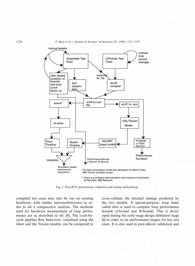
compiled test cases may also be run on existinghardware, with similar microarchitectures in or-der to do a comparative analysis. The methodsused for hardware measurement of loop perfor-mance are as described in ref. [8]. The cycle-by-cycle pipeline ¯ow behaviors, visualized using thetimer and the Texsim models, can be compared to
cross-validate the detailed timings predicted bythe two models. A special-purpose, loop timercalled eliot is used to compute loop performancebounds (I-bound and R-bound). This is devel-oped during the early-stage design de®nition stage[6] in order to set performance targets for key testcases. It is also used in post-silicon validation and
Fig. 2. Post-RTL performance validation and tuning methodology.
1124 P. Bose et al. / Journal of Systems Architecture 45 (1999) 1111±1137

tuning, as discussed later in this section. Eliot-based bounds computation can also be used topredict optimal loop unrolling depths, as discus-sed in Section 3.4.
3.1. Loop test cases
Table 1 lists a set of elementary Fortran DOLOOP test cases. These were compiled and (a) runon the actual hardware or the Texsim model; and(b) traced and run on the eliot tool for projectionof ``best-case'' and ``realistic'' bounds. Each loopwas unrolled to a depth indicated by the value of uin column 1. These loops, selected from a widerange of real applications, form the very basic setof application-based test cases used for assessmentof in®nite cache (¯oating point) performancetuning opportunities. (The actual list of test ker-nels used in practice is much larger, of course).
3.2. POWER3 loop performance
In this section, we compare the actual loopperformance of the POWER3 2 processor andcompare it with the (idealized) I-bound and (re-alistic) R-bound predictions as well as pre-siliconfull model timer runs. As indicated in Section 1,this processor is a (2 LSU, 2 FPU) processor,with many new features to provide enhancedperformance [6]. The data cache has two loadports and a single store port. However, the cachearray itself is 4-way interleaved, and bankcon¯icts prevent the e�ect of a true dual-portcache.
Table 1
Description of selected fortran loop test cases
TRACE (manual source
unroll, u� 2, is used
prior to auto-unroll)
Insrts/original
iteration
Loop body (original
u� 1, powerPC, assembly),
compiler xlf ver. 3.2.5.x
(Pre-POWER3)
Instrs/unrolled iteration
()O3 optimization to
invoke auto-unroll)
Loop body (original,
source)
Loop01.tr (u� 16) 2 {stfdu, bc} 17 x(i)� s
Loop02.tr (u� 8) 3 {lfdu, stfdu, bc} 17 x(i)� y(i)
Loop03.tr (u� 4) 5 {fadd, lfdu, lfdu, stdu, bc} 17 x(i)� a(i) + b(i)
Loop04.tr (u� 4) 5 {fadd, lfdu, lfd, stfdu, bc} 17 x(i)� x(i) + b(i)
Loop05.tr (u� 4) 4 {fadd, lfdu, stfdu, bc} 13 x(i)� u + a(i)
Loop06.tr (u� 4) 6 {fadd, lfdu, fadd, lfdu, stfdu, bc} 21 x(i)� u + a(i) + b(i)
Loop07.tr (u� 2) 8 {lfdu, fadd, lfdu, fadd, stfdu, lfdu,
fadd, bc}
15 x(i)� u + a(i) + b(i) + c(i)
Loop08.tr (u� 2) 9 {lfdu, fadd, lfdu, lfdu, fadd, lfdu,
fadd, stfdu, bc}
17 x(i)� a(i) + b(i) + c(i) + -
d(i)
Loop09.tr (u� 4) 6 {lfdu, lfdu, lfdu, fma, stfdu, bc} 21 x(i)� c(i) + b(i)�a(i)
Loop10.tr (u� 4) 6 {fmadd, lfd, lfdu, lfdu, stfdu, bc} 21 x(i)� x(i) + b(i)�a(i)
Loop25.tr (u� 4) 9 {fmadd, fmadd, lfdu, fmadd, lfdu,
fmadd, lfdu, lfdu, bc}
33 s1� s1 + b(i)�a(i) s2� s2+
b(i)�c(i) s3� s3 + d(i)�a(i)
s4� s4+ d(i)�c(i)
Daxpy.tr (u� 4) 5 {fmadd, lfdu, lfd, stfdu, bc} 17 x(i)� x(i) + s�y(i)
Ddot.tr (u� 4) 4 {fmadd, lfdu, lfdu, bc} 13 s� s + x(i)�y(i)
2 Measured numbers for POWER3 are based on Texism/
RTL simulation of the ®rst tape out model.
P. Bose et al. / Journal of Systems Architecture 45 (1999) 1111±1137 1125

Table 2 shows a comparison of the ``best-case''performance speci®cation bounds predicted by el-iot and the real performance of the (``taped-out'')POWER3 processor.2 All results assume or simu-late a perfect (in®nite) cache model. (Recall: Tex-sim is an RTL-level simulator of the integratedchip logic model, coded using an IBM internalhardware description language called DSL. Tex-sim simulation speed is about 50±100 target ma-chine cycles per second, which is too slow forperformance studies. Trace-driven timer modelspeeds are at least two orders of magnitude faster:hence their use in pre-silicon architecture analysisstudies.) The comparison data shown in Table 2were collected shortly after the ®rst tape-out forfabrication.
Columns (A) and (B) show ``best-case'' boundspredicted by the early-stage speci®cation timer,eliot (see Fig. 2 and related description). Column(A) shows the most optimistic (idealized) bounds,based on a true dual-load-ported, perfect datacache (without any interleave con¯icts) and withno execution cycle stalls for data dependencies inthe ¯oating point unit. Column (B) re¯ects amore realistic set of bounds, with stalls caused byfactoring in data cache interleave con¯icts and a2-cycle bubble caused by back-to-back data de-pendencies in the ¯oating point execution unit.Column (C) shows data obtained by the detailed,trace-driven POWER3 timer, which was devel-oped for pre-silicon analysis. Column (E) showsthe corresponding performance numbers obtained
Table 2
Eliot generated bounds vs timer vs Texsim model results (POWER3)
Loop-trace (as in Table 1,
with pre-POWER3
compiler)
``Best-case'' (eliot)
bounds (I-bound)
(A)
``Realistic''
achievable bounds
(R-Bound) (B)
POWER3 CPU
timer (C)
POWER3 timer
w/o interl. con¯.
(D)
Texsim (full RTL
model) (E)
cpiss cpiss cpiss cpiss cpiss
Loop01 (u� 16) 0.941 0.941 0.941 0.941 0.941
Loop02 (u� 8) 0.471 0.471 0.471 0.471 0.471
Loop03 (u� 4) 0.353 0.412 0.412 0.381 0.426
Loop04 (u� 4) 0.353 0.373 0.382 0.373 0.382
Loop05 (u� 4) 0.307 0.307 0.333 0.333 0.333
Loop06 (u� 4) 0.286 0.333 0.381 0.381 0.381
Loop07 (u� 2) 0.267 0.333 0.422 0.422 0.422
Loop08 (u� 2) 0.294 0.353 0.451 0.431 0.451
Loop09 (u� 4) 0.381 0.476 0.476 0.381 0.476
Loop10 (u� 4) 0.381 0.428 0.476 0.429 0.476
Loop25 (u� 4) 0.273 0.303 0.333 0.303 0.333
Ddot (u� 4) 0.307 0.615 0.923 0.923 0.923
Daxpy (u� 4) 0.353 0.353 0.382 0.382 0.382
Eliot bounds for column (A) assume absence of L1 interleaf con¯icts and 0-cycle bubble for back-to-back ®t op dependence.
Eliot bounds for column (B) assume L1 interleaf con¯icts, and 2-cycle bubble for back-to-back ®t op dependence, per current design
specs.
cpiss (stead-state cycles per instruction) is calculated from the steady-state part of the corresponding cycle-by-cycle listing for these loop
traces.
1126 P. Bose et al. / Journal of Systems Architecture 45 (1999) 1111±1137

from Texsim (RTL) model runs. Column (D)shows the timer run data obtained by turning o�interleaved data cache con¯ict checking. We seefrom Table 2 that the POWER3 timer and theTexsim models agree (exactly) for all the testcases considered, (cf. columns (C) and (E)) exceptfor loop03. (The discrepancy for loop03 wasfound to be due to a modelling error in the tim-er.) In comparing the eliot-speci®ed bounds withactual RTL model performance, we ®nd signi®-cant performance gaps in many of these basiccases, except for loop01 and loop02, where theexpectation was met precisely. These performancegaps pointed us immediately to post-silicon tun-ing opportunities.
Table 3 summarizes the diagnosis of the per-formance bugs and the initial set of recommen-dations, based on the results presented. These areunder current consideration by the design team, inleague with our compiler experts. The main de®-ciencies identi®ed are: (a) interleaved data cachecon¯ict-related stalls of the dual load-store unit;(b) ¯oating point operation issue stalls due to largevalues of the fpu_dep_delay (see Eq. (10b)) in thecurrently implemented design; (c) inability to fetchacross an I-cache line boundary in a given in-struction fetch cycle; and (d) an identi®ed perfor-mance bug in the initial ``tape-out'' RTL model,which causes stores to ®nish a cycle later than theyshould.
3.2.1. Loop unrolling and instruction scheduling;measured impact
Most, if not all of the hardware change rec-ommendations in Table 3, for example, have apossible compiler solution. However, in somecases, a general hardware ®x, if feasible, is thepreferred solution. In other cases, a hybrid hard-ware/software compromise solution may besought. For example a localized re-ordering tech-nique, using a crossbar to sort even/odd referencesand an ``address below'' register has been used in a
prior processor [10] (developed by Silicon Graph-ics) as a hardware aid to resolve con¯icts in theinterleaved data cache. This mechanism eases thelocal misalignment problem for the processor re-ferred to; but, as stated in [10], the compiler is stillexpected to be responsible for solving the globaleven/odd address mix problem.
Another example of software tuning is compilerloop transformation [12], which o�ers a knownpotential for ¯oating point performance enhance-ment. Loop unrolling, in particular, is an impor-tant transformation for enhancing ¯oating pointperformance in dual-fpu superscalar processorslike the POWER2, POWER3 or the TFP proces-sor [10]. Su�cient unrolling allows additional in-struction scheduling opportunities to the compilerwithin the loop body, and reduces the number ofloop-ending branches to be predicted. Excessiveunrolling, on the other hand, can cause overhead``spill code'' to be generated, or may cause in-struction dispatch stall cycles due to resourcelimits (e.g., the ®nite number of register renamebu�ers). In order to feed back POWER3-speci®cloop unrolling and scheduling heuristics to thecompiler group, we experimented with variousloop tuning alternatives.
Table 4 shows data from one such experimentusing the same loop traces described earlier. Weinitially used an older, pre-POWER3 compiler,which supported automatic loop unrolling, butwhich did not have a POWER3-speci®c schedul-ing option. With a ``-qtune� pwr2'' ¯ag, wecould obtain code scheduled with the POWER2processor organization [4,5,8] in mind; withoutthis option, the compiler generates code assuminga (1 LSU, 1 FPU) organization. Column (A)shows the performance data for codes obtainedby manually unrolling the given loop once, andthen applying compiler auto-unrolling. Column(C) is the same as Column (A), except that the ``-qtune� pwr2'' option was added. Column (B)also uses ``-qtune� pwr2'' but skipping the
P. Bose et al. / Journal of Systems Architecture 45 (1999) 1111±1137 1127

Ta
ble
3
Per
form
an
ceb
ug
dia
gn
osi
sta
ble
an
dre
com
men
ded
solu
tio
ns
Tes
tca
seD
evia
tio
no
fta
pe-
ou
t
mo
del
*p
erf
fro
m
elio
t-b
ase
d(b
est-
case
,
idea
lize
d)
spec
s(%
)
Pri
mary
cau
seo
f
dev
iati
on
,o
ro
fp
oo
r
per
form
an
ce
Sec
on
dary
cau
seP
oss
ible
®x(e
s),
or,
po
ssib
leen
han
cem
ents
per
form
an
ce
Cu
rren
tre
com
men
dati
on
Lo
op
01
~0
1st
ore
po
rt(D
cach
e)(E
�.)
2st
ore
po
rts
No
ne
Lo
op
02
0S
am
e;ab
ove
Sam
e;ab
ove
No
ne
Lo
op
03
17
.8D
cach
ein
terl
.co
n¯
icts
Ifet
ch/d
isp
rest
rict
ion
sT
rue
2-p
ort
edd
cach
e;
or,
mem
ory
re-q
ues
t
reo
rder
bu
�er
an
d/o
r
com
pil
erh
elp
Mem
.re
qu
est
reo
der
bu
�er
(RO
B)
sch
eme
+
com
pil
ersu
pp
ort
Lo
op
04
16
.7D
cach
ein
terl
.co
n¯
icts
Sam
e;ab
ove
Sam
e;ab
ove
Lo
op
05
9.1
Icach
eli
ne
cro
ssin
g,
ifet
ch/d
isp
rest
rict
ion
s
Ifet
chacr
oss
lin
e
bo
un
dary
insa
me
cycl
e
Inves
tigate
/h/w
logic
ad
d
to®
xp
rob
lem
Lo
op
06
31
.8®
t.p
ipe
dep
end
ency
del
ay
Tu
ne
ou
t-o
f-o
rder
¯t
dis
p.
an
dre
sult
for-
ward
ing
logic
;
com
pil
ertu
ne
Imp
rove
logic
,ci
rcu
it
des
ign
for
dep
.ch
eck
,
reo
rder
ing
Lo
op
07
54
.8S
am
e;ab
ove
Sam
e;ab
ove
Sam
e;ab
ove
Lo
op
08
29
.5S
am
e;ab
ove
Dca
che
inte
rl.
con
¯ic
tsS
eeab
ove
(lo
op
s06,0
3)
See
ab
ove
(lo
op
s06,0
3)
Lo
op
09
37
.4D
cach
ein
terl
.co
n¯
.F
lt.
pip
ed
ep.
stall
See
ab
ove
(lo
op
s03,
06)
See
ab
ove
(lo
op
s03,
06)
Lo
op
10
25
.7D
cach
ein
terl
.co
n¯
.F
lt.
pip
ed
ep.
stall
See
ab
ove
(lo
op
s03,
06)
See
ab
ove
(lo
op
s03,
06)
Lo
op
25
21
.9D
cach
ein
terl
.co
n¯
.If
etch
/dis
pre
stri
ctio
ns
See
ab
ove
(lo
op
s03,
05)
See
ab
ove
(lo
op
s03,
05)
dd
ot
99
.7¯
tp
ipe
dep
.S
eeab
ove
(lo
op
06)
See
ab
ove
(lo
op
06)
da
xp
y8
.21
late
sto
re®
nH
/w®
xH
/w®
x
1128 P. Bose et al. / Journal of Systems Architecture 45 (1999) 1111±1137

manual unrolling step used for Column (A).Column (D) shows the results obtained with anewer compiler, with some very preliminaryPOWER3-speci®c optimizations. The e�ectiveunrolling depth in each case is indicated by theparameter u.
The e�ect of initial unrolling of the source loopby hand (Columns (A) or (C)) was to reduce thenumber of ``load-¯oating-point-with-update'' orlfdu instructions, in favor of plain ``load-¯oating-point'' (lfd) instructions. The semantics of the lfdu
instruction in the PowerPC architecture [13] callsfor updating the address index (base) registercontents by the address computed in the current(lfdu) instruction. With machines like the POW-ER2 [4], in which a 3-input adder is available aspart of the address generation logic, such an in-struction can be executed (``®nished'') in a singlecycle. In the POWER3, such an instruction canstill execute in a single cycle, but if an immediatelyfollowing load instruction uses the same indexregister, it will not be able to execute concurrently
Table 4
Compiler scheduling sensitivity
Loop trace cpiss values for POWER3-Texsim (RTL) model runs
Old (pre-POWER3) compiler Newer compiler with some
(preliminary) POWER3-
speci®c scheduling (xlf ver.
4.1.0.3)
(a) Hand-unrolled once
(b) Then auto-unrolled ()O3)
(A)
(a) Auto unrolled ()O3)
(b) qtune�pwr2
(B)
(a) Hand-unrolled once
(b) Then auto-unrolled
()O3) (c) qtune�pwr2
(C)
Auto-unrolled ()O3)
(D)
Loop01 0.941 (u� 16) 0.889 (u� 8) 0.941 (u� 16) 0.889 (u� 8)
Loop02 0.471 (u� 8) 0.471 (u� 8) 0.471 (u� 8) 0.485 (u� 16)
Loop03 0.426 (u� 4) 0.412 (u� 4) 0.441 (u� 4) 0.470 (u� 8)
Loop04 0.382 (u� 4) 0.412 (u� 4) 0.455 (u� 4) 0.409 (u� 8)
Loop05 0.333 (u� 4) 0.385 (u� 4) 0.333 (u� 4) 0.320 (u� 8)
Loop06 0.381 (u� 4) 0.321 (u� 4) 0.321 (u� 4) 0.341 (u� 8)
Loop 07 0.422 (u� 2) 0.333 (u� 2) 0.356 (u� 2) 0.336 (u� 4)
Loop08 0.451 (u� 2) 0.467 (u� 2) 0.364 (u� 2) 0.432 (u� 4)
Loop09 0.476 (u� 4) 0.619 (u� 4) 0.619 (u� 4) 0.500 (u� 8)
Loop10 0.476 (u� 4) 0.537 (u� 8) 0.476 (u� 4) 0.512 (u� 8)
Loop25 0.333 (u� 4) 0.471 (u� 2) data not avail. 0.424 (u� 8)
daxpy 0.353 (u� 4) 0.485 (u� 8) 0.394 (u� 4) 0.409 (u� 8)
ddot 0.923 (u� 4) 0.960 (u� 8) 0.960 (u� 4) 0.385 (u� 4)
Remarks partial manual unrolling
reduces number of lfdu's
too many lfdu's; hurts
many loops
partial manual unrolling
reduces number of lfdu's
lfdu problem still present
Qtune�pwr2 helps
reduce penalty due to
¯t pipe dep. delays
POWER3-speci®c schedul-
ing does an even better job
of reducing penalty due to
¯t pipe dep. delays
(esp. ddot)
P. Bose et al. / Journal of Systems Architecture 45 (1999) 1111±1137 1129

with the lfdu. Thus a general heuristic which en-ables reduction of the number of lfdu's generatedwill help boost POWER3 loop performance; or, inparticular, lfdu±lfd pair generation (with a com-mon index register) should be avoided in aPOWER3-speci®c compiler switch. This is ob-servable from the data in Table 4: column (B)shows degraded performance compared to column(A) in a majority of the cases. It bene®ts in caseswhere the code is compute-intensive, and is furtherenhanced by improved code scheduling (``-qtu-ne� pwr2'').
In comparing columns (C) and (D), we see thatthe biggest improvement achieved in the newerversion of the compiler (with a POWER3-speci®coptimization switch) is re¯ected in the perfor-mance of the dot product loop test case, ddot. Thisloop exhibited the worst performance gap from theeliot-predicted early bounds speci®cation (see Ta-bles 2 and 3) when using the older compiler.However, the problem caused by generation ofexcessive (lfdu±lfd) sequences is still seen in thenewer results. Also, the loop unrolling depths usedby the compiler is not always optimal, from thepoint of view of steady-state loop cpi values. Notethat with auto-unrolling, the old and new com-pilers do not always use the same unrolling depths(cf. columns (B) and (D)). In a recent paper [14],we presented methods for predicting the ``best''loop unrolling depths for POWER3-like machines,using static bounds-based heuristics. We touch onthis issue brie¯y in Section 3.4.
It should be noted that the steady state loop cpivalues (cpiss) shown in Tables 2 and 4 can beslightly misleading when comparing the total exe-cution times for a ®nite number of iterations of theoriginal (not unrolled) loop. A more meaningfulmetric to use, in such studies, may be cycles perlogical (not unrolled) iteration, cpI. The relationbetween cpiss and cpIss is given by
cpIss � �cpiss � ipI�=u �11�
where ipI denotes the number of instructions periteration in the unrolled loop and u is the depth ofunrolling. (Note: upper case I is used to abbreviateiteration; lower case i stands for instruction.) Thus,for example in loop01, the original (not unrolled)loop body consists of a single ¯oating point storewith update (stfdu) followed by the loop-endingbranch, so ipI� 2 for u� 1. With u� 8 (columns(B) or (D)), we have ipI� 9 (8 stores plus abranch); with u� 16 (columns (A) or (C)), ipI� 17(16 stores plus a branch). With these values, thecpIss value (using Eq. (11)) for any of the columns(A), (B), (C), or (D) for loop01 would be 1.0. Thatis, the steady-state cycles per (logical) iterationperformance for loop01 is 1.0, irrespective of thecompiler options experimented with (Table 4).
In the POWER2/P2SC loop performance tun-ing studies reported in Section 3.3, we use the cy-cles-per-(logical)-iteration (cpI) metric as the basisof evaluation.
3.3. POWER2 and P2SC loop performance
The POWER2 (and P2SC) in®nite cache,¯oating point microarchitecture is similar to thatof the POWER3, in that both are (2 LSU, 2 FPU)machines. There are some important distinctions,though. The POWER2 architecture has the load/store ¯oating point quadword instructions (seeSection 2); POWER3 does not. On the other hand,the POWER3 has a branch target address cache(BTAC) [3] mechanism for fetch prediction, whicheliminates fetch stalls for loop-ending branches.
Let us ®rst examine some comparative perfor-mance data to understand the characteristics ofPOWER2. These data illustrate how the perfor-mance may vary drastically, even though the basicorganization is still a (2 LSU, 2 FPU)-structureand the compiler version is unchanged. Table 5shows the comparative ``cycles per logical itera-tion'' (cpI) performance of POWER2 and POW-ER3. The POWER3 data shown are of course
1130 P. Bose et al. / Journal of Systems Architecture 45 (1999) 1111±1137

based on the latest available RTL simulation re-sults, with the latest available compiler (column(D) data in Table 4). The POWER2 hardwaremeasurement data are reported for the samecompiler, but with two di�erent options of theinstruction set architecture. The ``-qarch� com''mode generates code in the so-called ``common''mode, which implies an ``intersection'' of POW-ERä, POWER2ä PowerPCä architecture opcodedomains (see Ref. [13]). The -qarch� pwr2 allowsthe use of additional instruction opcodes which areunique to the POWER2 machine: in particular, the¯oating point load and store quadword instructions(see Section 2).
We see from Table 5, that in terms of archi-tectural (cycles-per-iteration) performance, thePOWER2 does better than the initial tape-outversion of POWER3 (and compiler) for many ofthe elementary loop test cases considered in thispaper. (Of course, the POWER3's MHz perfor-mance is considerable higher than that of the latestPOWER2 and P2SC processors. Also, in terms ofreal, ®nite cache performance, which is beyond thescope of this paper, other features like data cache
prefetch enable the POWER3 to meet pre-silicontargets. The POWER3 design factors in require-ments for server products with a broader overallmarket than its predecessors. It provides forPowerPC architecture compatibility, superior in-teger/branch performance and support for multi-processing. As stated in Section 1, overall systemperformance and tuning issues are not dealt within this paper.)
The amount of bene®t exploited by POWER2using load/store quadword instruction support canbe seen by comparing data columns 1 and 2 ofTable 5. Once the e�ect of load/store quads isfactored out, the POWER3 performance (datacolumn 3) compares favorably with POWER2performance (data column 1): in a couple of cases(loop05 and loop07) the POWER3 actually doesquite a bit better, because of its superior out-of-order instruction scheduling.
Let us now examine the loop performancecharacteristics of the POWER2/P2SC microarchi-tecture in detail. In Table 6, we present loop per-formance data measured on a 160 MHz P2SCprocessor, using the latest available compilers. We
Table 5
POWER3 cycles-per-Iteration (cpI) comparison with POWER2 hardware measurements
POWER2 ()qarch� com) POWER2 ()qarch� pwr2) POWER3 RTL simulation
()qarch� com)
Loop01 0.84 0.42 1.0
Loop02 1.02 0.51 1.0
Loop03 1.77 1.01 1.94
Loop04 1.52 0.89 1.69
Loop05 1.27 1.20 1.0
Loop06 1.65 1.52 1.75
Loop07 3.53 1.53 2.44
Loop08 3.54 1.57 2.56
Loop09 2.03 1.57 2.56
Loop10 2.03 1.54 2.63
Loop25 2.53 2.53 2.5
Ddot 1.02 0.77 1.25
Daxpy 1.78 0.89 1.69
P. Bose et al. / Journal of Systems Architecture 45 (1999) 1111±1137 1131

compare this with predicted I- and R-bounds. Wehave also listed the primary hardware constraintswhich inhibit attainment of the ``best-case'' I-bounds.
As before, the e�ective unroll factor (u) isshown for each loop in Table 6. For lack of space,it is not possible to discuss each loop in detail. Letus consider a couple of the ones which exhibit alarge gap between the I-bound and either thecorresponding R-bound or the actual measuredperformance. These loops are: loop01, loop05,loop06 and loop08. Of these, loop05 and loop06have the same underlying cause being their per-formance shortfall. Let us consider loop01 andloop05 in some detail. The compiled code sequenceof interest for loop01 is:
stfq 31, 0, 16(3)stfq 31, 0, 32(3)
stfq 31, 0, 48(3)stfqu 31, 0, 64(3)bc
Note that store quadword instructions havebeen used, since they are available on the POW-ER2 and P2SC machines. Each stfq correspondsto two stfd instructions and hence two iterationsof the original, not-unrolled loop (see Table 1).Thus, clearly, the e�ective unrolling depth in-voked by the compiler in this case is u� 8. Eachstfq instruction stores the pair of ¯oating pointregisters: #31 and #0. The two doublewords (orone quadword) forming the data are stored at theaddress speci®ed by a displacement and a baseaddress register. The latter is speci®ed to be the®xed point register #3 in each case. The di�erencebetween two successive displacements (e.g., 16and 32) is 16 bytes, which is one quadword. Since
Table 6
Actual measured performance (cycle per iteration, cpI): P2SC
Loop Current xlf
compiler a
Current xlhpf
com-piler b
I-Bound R-Bound Primary h/w
bottlenecks
Compiler solution?
Loop01 (u� 8) 0.43 0.43 0.25 0.417 store-q size No
Loop02 (u� 8) 0.52 0.52 0.50 0.50 ± ±
Loop03 (u� 4) 0.89 0.89 0.75 0.85 Store-q, re-name
bu�s
No
Loop04 (u� 4) 0.85 0.85 0.75 0.85 As above As above
Loop05 (u� 4) 1.01 1.01 0.50 1.0 Store-add anti-dep.,
renames
Unroll deep-er, s/w
pipeline
Loop06 (u� 4) 1.76 1.76 1.0 1.25 As above As above
Loop07 (u� 4) 1.66 1.53 1.5 1.5 ± ±
Loop08 (u� 4) 3.02 2.28 1.5 1.75 Rename bu�s Improved reg alloc
Loop09 (u� 4) 1.15 1.14 1.0 1.15 As above As above
Loop10 (u� 4) 1.15 1.14 1.0 1.15 As above As above
Loop25 (u� 4) 2.07 2.06 2.0 2.0 comp. bound (2
FPU), reg pressure
Better schedule
Daxpy (u� 8) 0.85 0.85 0.75 0.85 See loop03 See loop03
Ddot (u� 4) 0.77 0.77 0.50 0.75 Load-fma direct dep. Schedule
a xlf version 4.1.04, with )O3 )qarch�pwr2.b xlhpf verion 1.2. with )qnohpf )O3 )qarch�pwr2.
(In using xlhpf, a new, improved register allocator is invoked.)
1132 P. Bose et al. / Journal of Systems Architecture 45 (1999) 1111±1137

the number of LSU's is 2, and the number ofstore-ports is 2, it is easy to see that the steadystate cycles per iteration bound of this loop is 4/2� 2. (The branch is overlapped with store exe-cution). However, one iteration of this loop cor-responds to eight iterations of the original loop.Hence, the steady-state cycles-per-(logical)-in-struction I-bound is: cpI� 2/8� 0.25.
The actual measured performance for this loopon the P2SC is cpI� 0.43. Since the code consistsessentially of a sequence of stores, the primarysuspect in terms of ®nite hardware resources, isclearly the pending store queue. For this machine,the size of this queue is six. As veri®ed throughexact cycle-by-cycle simulation data, thislimitation causes the actual, steady-state comple-tion pattern of stores (stfq's) to be:2±2±2±0±0±2±2±2±0±0± . . .; i.e., three consecutivepairs of completion, followed by two stall cycles.This results in a cycle count of ®ve cycles for 12(original, not-unrolled) iterations, which gives:cpI� 5/12� 0.417. The stalls happen because ofthe latency mismatch between the address gener-ation path and the path which reads the storedata from the source registers and writes it intothe store queue. Let us denote these two pipelatencies to be agen_pipe and sdata_pipe. If thesee�ective latency numbers are factored into thebounds model, the stall pattern above can bepredicted. If (sdata_pipe-agen_pipe) > 3, thenafter every three cycles (or six stfq agens), thestore queue ®lls up, causing a stall. The numberof stall-cycles can easily be shown to be given by(sdata_pipe-agen_pipe-2). For the P2SC, sda-ta_pipe� 5 and agen_pipe� 1. (Note, these arethe e�ective values of these latencies under steady-state processing of the loop shown. The hardwarelatency of the sdata_pipe is actually only 3.However, an agen-stall occurs a cycle before thestore queue ®lls up. Similarly, there is a cycle lossbecause a cache-array write from the head of thestore queue begins a cycle after the store data is
paired with the store address in the queue. Thisresults in an e�ective sdata_pipe latency of3 + 1 + 1� 5. The two extra latency cycles aresubtracted out during the calculation of thenumber of stall cycles. This is because, the agen-stall is eliminated immediately after the storequeue begins to get drained). Thus, the R-bound(� 0.417) generated by eliot agrees with simula-tion-based expectations for the P2SC microar-chitecture.
Given the nature of the hardware constraint,which results in an R-bound of about 0.42, it isquite clear that changes to the loop unrollingdepth will not help in reducing the gap between I-bound and R-bound in this case. Irrespective ofthe unrolling depth, the e�ective code sequence is astring of stores, which results in the stall patternshown. Of course, the use of store quadword in-structions helps; use of the lower bandwidth stfduinstructions would glean a cpI of 0.84 (see Table 5,®rst data column).
For loop05, the compiler-generated loop bodyis as follows:
stfq 0, 1, 16(4)stfqu 6, 7, 32(4)fadd 0, 31, 2fadd 1, 31, 2lfq 2, 3, 16(3)fadd 6, 31, 4fadd 7, 31,5lfqu 4, 5, 32(3)bc
In I-bound mode, the steady-state issue groupswould be: (stfq, stfqu, fadd, fadd) and (lfq, fadd,fadd, lfqu, bc), yielding a rolled-loop cpI of 2.Since the e�ective unrolling depth is u� 4, the realI-bound is cpI� 2/4� 0.5. The actual measuredperformance is 1.01, which is half the speed of the``best-case'' expectation. The reason behind theperformance gap is not hard to infer: the data
P. Bose et al. / Journal of Systems Architecture 45 (1999) 1111±1137 1133

dependencies between the stores and the subse-quent fadd instructions. In the POWER2 andP2SC implementations, target register renaming issupported only for ¯oating point loads, not forfunctional operations. Thus the anti-dependencybetween the ®rst stfq and the ®rst fadd (via register#0), causes an issue stall of (sdata_pipe-agen_pipe-1)� (3)1)1)� 1 cycle. Note that in this case, thee�ective value of sdata_pipe is equal to the hard-ware latency of three stages, since there is no agen-stall to be considered. The other one cycle savingoccurs due to store data forwarding to the FPUpipe. Thus, the steady-state issue groups, in R-bound mode are: (stfq, stfqu), ( ), (fadd, fadd, lfq),(fadd, fadd, lfqu, bc). This gives a rolled-loop cpIof 4 and the ®nal R-bound cpI is 4/4� 1, whichmatches the hardware measurement.
Anytime there are dependency-caused stalls asabove, the question to ask is: can the I-bound bemet or approached through better register alloca-tion and/or scheduling? In such situations, it isoften the case that deeper unrolling exposes betteropportunities to create a schedule which is free ofdependence-stalls. In the above case, by usingmanual unrolling at the source-level, we were ableto coax the compiler into generating a software-pipelined schedule, with a measured cpI of 0.64.The inner loop of interest in this case was as fol-lows:
stfq 2, 3, 16(4)fadd 4, 31, 4lfq 2, 3, 16(3)fadd 5, 31, 0stfq 6,7, 32(4)fadd 1, 31, 1lfq 6,7, 32(3)fadd 0, 31, 0stfq 4, 5, 48(4)fadd 2, 31, 2lfq 4, 5, 48(3)fadd 3, 31, 3
stfqu 0, 1, 64(4)fadd 6, 31, 6lfqu 0, 1, 64(3)fadd 7, 31, 7bc
This schedule eliminates the dependence-stalland results in a rolled cpI of 4, and an I-bound cpIof 4/8� 0.5. The degraded value of the measuredcpI (0.64) can now be explained as being due todispatch stalls resulting from rename bu�er pres-sure. Since the renamed loads run ahead of thecomputation (due to the longer latency FPUpipes), there are eventually stall created because oflack of free rename bu�ers. For the above case, itcan be shown that the e�ective rolled cpI becomes5, yielding an R-bound of 5/8� 0.63, whichmatches the measured performance.
3.4. Prediction of optimal loop unrolling depth
In this section, we brie¯y illustrate the use ofbounds-based characterization in determining asuitable loop unrolling depth in order to get thebest performance [14]. This is a topic of ongoingwork and the details of the unrolling algorithmswill be reported later in a separate report. Here, wediscuss the basic concept only, with the use of asimple example from our suite of loops.
Let us consider loop03 which is the third loop inour suite. The compiled code for the innermostloop for a certain compiler version (without un-rolling, i.e., with u� 1) was:
lfd 0; 0 x 808�4�lfd 1; 0 x 1608�1�fadd 0, 0, 1stfdu 0; 0 x 8�4�bc
The compiled codes for u� 2 and u� 3 are alsogiven below:
1134 P. Bose et al. / Journal of Systems Architecture 45 (1999) 1111±1137

For u� 1, and a (1 LSU, 1 FPU)-machine,performance is load-store bound. The steady-state,idealized cycles-per-instruction (cpi) and cyclesper-¯op (cpf) performance of loop03 can be com-puted using the simple bounds model as being:(cpI� 3) ) cpi� 0.6 and cpf (cycles per ¯oatingpoint operation)� 3.0. For u� 2, it is still load-store (agen) bound, and the idealized performanceis: (cpI� 6) ) cpi� 0.66, cpf� 3.0. For u� 3, wehave: (cpI� 9) ) cpi� 0.69, cpf� 3.0. For u� 4,we would have: (cpI� 12) ) 0cpi� 0.705,cpf� 3.0. In general, we would have: cpI� 3 * uand N� 4 * u + 1, and NF� u. From these, theabove values can be computed.
Thus, for a (1LSU, 1FPU)-machine, it wouldnot pay to unroll a loop like that illustrated aboveto get additional ¯oating point performance. Thisis clear from simple bounds-based reasoning, butwas veri®ed via detailed timer runs.
Let us now look at an enhanced design: a (2LSU,2FPU)-machine, like POWER3, with l_ports� 2,s_ports� 1, and disp_bw� compl_bw� 4. Theloop performance (with or without unrolling) is stillagen-bound; however, now we can see a bene®t inunrolling. For u� 1, we have: (cpI� é3/2ù� 2) )cpi� 0.4 and cpf� 2.0. For u� 2, we get: (cpI� é6/
2ù� 3)) cpi� 0.33, cpf� 1.5. For u� 3, we have:(cpI� é9/2ù� 5)) cpi� 0.38, cpf� 1.67. For u� 4,we get: (cpI� é12/2ù� 6) ) cpi� 0.353, cpf� 1.5.In general, we would have: cpI� é(3 * u)/2ù,N� (4 * u) + 1, and NF� u. From these, the abovevalues can be computed. Clearly, from an idealized,steady-state cpf (mega¯ops) performance, u� 2, 4,6,... etc would result in the optimal performance ofcpf� 1.5. However, in the real case, due to otherlimits like the number of rename bu�ers or the sizeof the reorder bu�er, etc., performance would ac-tually go down for higher choices of u. In fact, usinga pre-silicon timer (e.g., H-timer; see Fig. 2) weveri®ed that for a POWER3, performance actuallydegrades for u� 6 and beyond.
4. Conclusion
We have presented the practical use of a simple,bounds-based analysis method in the context ofpost-silicon loop performance validation andtuning. After the microprocessor chip is back fromthe silicon fabrication process, the ®rst concern, ofcourse is functional validation. Once the key testcases are operational (i.e., they produce correctresults), the next concern is performance. The post-silicon analysis and tuning experiments generateknowledge and understanding required for ma-chine-speci®c compiler tuning. In order to validateperformance, one needs to know what the desiredspeci®cations (or targets) are. Bounds-basedanalysis provides a means for ®xing a range ofsuch targets: from the ``best-case'' or idealized, toa more practical, achievable one. Comparison ofthe idealized and realistic bounds tells us howmuch degradation is caused by hardware resourceconstraints and data dependencies. Comparing thebounds with the actual performance data allows usto assess the e�ectiveness of the (microarchitec-ture, compiler) pair. In some cases, it is possible tosuggest very speci®c compiler enhancement ideasto bridge the observed performance gap.
u� 2 u� 3lfd 0; 0 x 808�4� lfd 0; 0 x 808�4�lfd 1; 0 x 1608�4� lfd 1; 0 x 1608�4�fadd 2, 0, 1 fadd 3, 0, 1lfd 0; 0 x 816�4� lfd 2; 0 x 1624�4�lfd 1; 0 x 1616�4� lfd 0; 0 x 816�4�fadd 0, 0, 1 lfd 1; 0 x 1616�4�stfd 2; 0 x 8�4� fadd 1, 0, 1stfdu 0; 0 x 8�4� stfd 3; 0 x 8�4�bc lfd 0; 0 x 824�4�
fadd 0, 0, 2stfd 1; 0 x 16�4�stfdu 0; 0 x 24�4�bc
P. Bose et al. / Journal of Systems Architecture 45 (1999) 1111±1137 1135

Loop performance can be a crucial determinantof overall ¯oating point performance. As reportedearlier [15], a simple hardware ``®x'' to achieve thedaxpy performance I-bound for a pre-POWER3design point resulted in a SPECfp92 performanceboost of 14%. (Since this performance bug had todo with store instruction latency and store queuesize, the solution led to an unexpected 11% boost inSPECint92 performance as well.) In this paper, weillustrated the application of bounds-based analy-sis to post-silicon diagnosis and tuning for two ofthe most recent super scalar processors developedby IBM. Both of these processors are designed toprovide superior ¯oating point performance, andare targeted for high-end RS/6000 workstationsand servers. We discussed the basic concepts andtheir application in the context of a few applica-tion-based loop kernels. In practice, a suite of wellover 100 loops and other test cases, along withother applications are used in our post-siliconperformance validation and tuning exercises.
References
[1] G.F. Grohoski, Machine organization of the IBM RISC
System/6000 processor, IBM J. Res. Develop. 36 (1) (1990)
37±58.
[2] S. Song, M. Denman, J. Chang, The PowerPC 604 RISC
microprocessor, IEEE Micro, October 1994, pp. 8±17, .
[3] D. Levitan, T. Thomas, P. Tu, The PowerPC 620TM
microprocessor: a high performance superscalar RISC
microprocessor, Proceedings of COMPCON, March 1995,
pp. 285±291.
[4] S.W. White, S. Dhawan, POWER2: Next generation of
the RISC system/6000 family, in PowerPC and POWER2:
technical aspects of the new IBM RISC system/6000, IBM
Corporation, Publication no. SA23-2737-00, 1994.
[5] L. Gwennap, IBM crams Power2 on to single chip,
Microprocessor Report, 26 August, 1996.
[6] H.Q. Le, P. Bose, D. Schroter, M. May®eld, Design point
de®nition of the core microarchitecture of a high end
PowerPCTM processor (under clearance for publication).
[7] P. Bose, S. Surya, Architectural timing veri®cation of
CMOS RISC processors, IBM J. Res. & Develop. 39 (1/2)
(1995) 113±129.
[8] E.L. Hannon, F.P.O' Connell, L.J. Shieh, POWER2
performance on engineering/scienti®c applications, in
PowerPC and POWER2: Technical Aspects of the New
IBM RISC/System/6000TM, IBM Publication no. SA23-
2737-00, 1994; see also, Proceedings of ICCD, October
1994, pp. 336±339.
[9] J.E. Smith, A.R. Pleszkun, Implementation of precise
interrupts in pipelined processors, Proceedings of the
International Symposium on Computer Architecture
(ISCA), 1985, pp. 36±44.
[10] P.Y.-T Hsu, Design of the TFP Microprocessor, Proceed-
ings of the IEEE Micro, 1994.
[11] W. Magione-Smith, T.P. Shieh, S.G. Abraham, E.S.
Davidson, Approaching a machine application-bound in
delivered performance on scienti®c code, Proceedings of
the IEEE, vol. 81, August 1993, pp. 1166±1178.
[12] D.F. Bacon, S.L. Graham, O.J. Sharp, Compiler trans-
formations for high-performance computing, ACM Com-
puting Surveys 26 (4) (1994) 345±420.
[13] C. May, E. Silha, R. Simpson, H. Warren, (Eds.), The
PowerPC Architecture: A Speci®cation for a New Family
of RISC Processors, Morgan Kaufmann, San Francisco,
CA, 2nd ed., May 1994.
[14] P. Bose, J.-D. Wellman, Compiler-aided loop tuning
opportunities for high-end PowerPCTM Machines, Pro-
ceedings of the Workshop on Interaction between Com-
pilers and Computer Architectures (held in conjunction
with third International Symposium on High-Performance
Computer Architecture, HPCA-3), Feb. 1997; available as
an IBM Research Report.
[15] P. Bose, Performance analysis and veri®cation of super
scalar processors, IBM Research Report RC 20094, June
1995; parts of this were presented as a talk at the ISCA-95
workshop on pre-silicon performance analysis and valida-
tion, Santa Margherita, Italy, 1995.
Pradip Bose received his B.Tech degreein Electronics and Electrical Commu-nication Engineering from the IndianInstitute of Technology, Kharagpur,India, in 1977 and the M.S. and Ph.Ddegrees in Electrical and ComputerEngineering from the University of Il-linois, Urbana±Champaign, USA, in1981 respectively. Since May 1983, Dr.Bose has been a Research Sta� Mem-ber at the IBM T.J. Watson ResearchCenter, Yorktown Heights, NY. Dur-ing 1992±94, Dr. Bose was on assign-ment at IBM Austin, where he served
as the lead performance engineer during the de®nition andevaluation of a processor, which eventually evolved into IBM's
1136 P. Bose et al. / Journal of Systems Architecture 45 (1999) 1111±1137

POWER3 microprocessor. During the 1989±90 academic year,Dr. Bose was a Visiting Associate Professor at Indian SatisticalInstitute, Calcutta, India as part of a sabbatical leave assigmentfrom IBM. During that year, he worked on application of ar-ti®cal intelligence techniques in the ®elds of VLSI CAD andmedical diagnosis. Dr. Bose has been active in many areas ofcomputer science and engineering. His current research interestinclude: high performance (super scalar, vector and parallel)computer architectures, compilers, digital testing and designautomation. Dr. Bose is an active member of various confer-ence committees. He is the author or co-author of over 50refereed publications and 1 book (MIT Press, to appear in1999).
Sunil Kim recieved his B.S. and M.S.from the Seoul National University,Korea and the Ph.D. in computer sci-ence from the University of Illinoise atUrbana±Champaign in 1995. Hejoined IBM, Austin and is currentlyinvolved in a high-end PowerPC pro-cessor development. His research in-terest are macro architectures, memorysystem, multiprocessor system, per-formance modeling and veri®cation.
Francis P. O'Connell senior Engineer,RS/6000 Development, IBM, Austin,TX, USA, has been a member of theRS/6000 high-end processor develop-ment e�ort since 1992. He has focussedon scienti®c and technical performancewithin IBM for the past 12 years. Herecieved his B.S. degree in engineeringin Mechanical Engineering from theUniversity of Connecticut in 1980 andan M.S. degree in Engineering/Eco-nomics systems from the StanfordUniversity in 1983.
William A. Ciarfella is the manager ofthe performance group in charge ofPOWER3 evaluation at IBM Austin.He has served as performance managerof prior development project withinIBM for the past seven years.
P. Bose et al. / Journal of Systems Architecture 45 (1999) 1111±1137 1137