developing a compiler for the xeonphi
TRANSCRIPT

Cockshott, William Paul, Oehler, Susanne, and Xu, Tian (2014) Developing a compiler for the XeonPhi (TR-2014-341). Technical Report. University of Glasgow, Glasgow Copyright © 2014 The Authors A copy can be downloaded for personal non-commercial research or study, without prior permission or charge Content must not be changed in any way or reproduced in any format or medium without the formal permission of the copyright holder(s)
When referring to this work, full bibliographic details must be given
http://eprints.gla.ac.uk/93597/
Deposited on: 23 May 2014
Enlighten – Research publications by members of the University of Glasgow http://eprints.gla.ac.uk
Developing a compiler for the XeonPhi
Paul Cockshott, Susanne Oehler and Tian Xu
Contents
1 Features of the XeonPhi . . . . . . . . . . . . . . . . . . . . . . . . . . . . . . . . . . . . . . . 21.1 Pascal Parallelism Mechanism . . . . . . . . . . . . . . . . . . . . . . . . . . . . . . . . . . . 32 The existing targeting mechanism . . . . . . . . . . . . . . . . . . . . . . . . . . . . . . . . . 33 Vectorisation . . . . . . . . . . . . . . . . . . . . . . . . . . . . . . . . . . . . . . . . . . . . 43.1 Vectorisation Solutions . . . . . . . . . . . . . . . . . . . . . . . . . . . . . . . . . . . . . . . 53.2 Pre-fetching . . . . . . . . . . . . . . . . . . . . . . . . . . . . . . . . . . . . . . . . . . . . . 64 Glasgow Vector Pascal performance tests . . . . . . . . . . . . . . . . . . . . . . . . . . . . . 84.1 Multi-core issues . . . . . . . . . . . . . . . . . . . . . . . . . . . . . . . . . . . . . . . . . . 94.2 Image scaling . . . . . . . . . . . . . . . . . . . . . . . . . . . . . . . . . . . . . . . . . . . . 94.3 Image convolution . . . . . . . . . . . . . . . . . . . . . . . . . . . . . . . . . . . . . . . . . 114.4 Accuracy issues . . . . . . . . . . . . . . . . . . . . . . . . . . . . . . . . . . . . . . . . . . . 124.5 Scaling and Convolution with Pre-fetching . . . . . . . . . . . . . . . . . . . . . . . . . . . . . 134.6 Fused Multiply-Accumulate . . . . . . . . . . . . . . . . . . . . . . . . . . . . . . . . . . . . 14
4.6.1 Caching . . . . . . . . . . . . . . . . . . . . . . . . . . . . . . . . . . . . . . . . . . . 144.7 Performance comparison with a GPU . . . . . . . . . . . . . . . . . . . . . . . . . . . . . . . 155 Conclusions and Future Work . . . . . . . . . . . . . . . . . . . . . . . . . . . . . . . . . . . . 19
Abstract
The XeonPhi[1] is a highly parallel x86 architecture chip made by Intel. It has a number of novel features whichmake it a particularly challenging target for the compiler writer. This paper describes the techniques used to portthe Glasgow Vector Pascal Compiler (VPC) to this architecture and assess its performance by comparisons of theXeonPhi with 3 other machines running the same algorithms.
This work was done as part of the EU funded CLOPEMA project whose aim is to develop a cloth folding robot.Within the overall context of the project it was necessary to develop a high resolution stereo vision head. This headuses a pair of 16 mega pixels colour cameras with servo controlled pan and tilt units to obtain 3D representationsof the cloth, that is to be folded. At the start of the project we used a Java legacy software package, C3D[2] thatis capable of performing the necessary ranging calculations. Whilst this gave very accurate measurements, thepackage had originally been developed to work with standard TV resolution images. When applied to modern highresolution images it was prohibitively slow for real time applications, taking about 20 minutes to process a singlepair of images.
To improve performance, a new Parallel Pyramid Matcher (PPM) was written in Vector Pascal[3], using thelegacy software as design basis. The new PPM allowed the use of both SIMD and multi-core parallelism[4]. Itperforms about 20 times faster on commodity PC chips such as the Intel Sandybridge, than the legacy software.With the forthcoming release of the XeonPhi it was anticipated to be able to obtain further acceleration running thesame PPM code on the XeonPhi. Hence, taking advantage of more cores and wider SIMD registers, whilst relyingon the automatic parallelisation feature of the language. The key step in this would be to modify the compiler toproduce XeonPhi code.
1
1 Features of the XeonPhi
The XeonPhi is a co-processor card, with one Many-Integrated-Core (MIC) chip on a PCI board, that plugs intoa host Intel Xeon system. The board itself has its own GDDR5 memory. The MIC chip, on the XeonPhi 5110P[5], contains 60 cores, each with its own cache. Each core is in addition 4-way hyperthreaded. Shared coherentaccess to the caches allows the chip to run a single Linux image. Using the pthreads library a single Linuxprocess may fork threads across different cores and sharing the same virtual memory.
The individual cores are a curious hybrid. The chip supports early versions of legacy x86 and x87 instructionsequivalent to those supported on the original Pentium processor, except that the basic register architecture isderived from the AMD Opteron with 16 × 64bit general purpose registers. The Linux image runs in 64bit modewith a modified AMD Application Binary Interface. However, all late model x86 instructions have been elided.There are no MMX, SSE or AVX instructions, nor are registers used for these instruction present. Moreover anumber of the now standard x87 instructions like FCOMI and FCMOV, which date from the late 1990s, are nolonger supported.
To make up for these deletions a whole set of new and unique instructions have been added[6]. Theseresemble AVX instructions by working with SIMD registers and employing a 3 operand format instead of Intel’sfavoured 2 operand format. However, the binary representation and the assembly syntax are different from AVX.Also SIMD registers are longer, 512 bits verses the 256 bits in AVX. Key features of the new instructions are:
• The ability to perform arithmetic on 16 pairs single precision floating point numbers using a single instruction- this is a simple extension of what AVX can do.
• Individual bits of 16 bit mask registers can be set based on comparisons between 16 pairs of floating pointnumbers.
• The usage of mask registers to perform conditional writes into memory or into vector registers.
• On the fly conversions between different integer and floating point formats, when loading vector registersfrom memory.
• Performing scattered loads and stores using a combination of a vector register and a general purposeregister.
The last point is the most novel feature of the architecture. Let us consider the following Pascal source codesamples:
for i:=0 to 15 do x[i]:= b[a[i]];
I.e. we want to load x with a set of elements of b selected by a, where x and b are arrays of reals and a is anarray of integers. Vector Pascal allows us to abbreviate this to:
x:=b[a]
The key step, the expression b[a] in this can in principle be perfomed on the MIC as
knot k1,k01:vgatherdps ZMM0{k1},[r15+ ZMM8*4 ]jknzd k1,1b
We assume that r15 points at the base address of array b. ZMM8 is a vector register that has been preloadedwith a, and ZMM0 is the register that will subsequently be stored in x. What the assembler says is
1. Load mask register k1 with 0FFFFH.
2. Load multiple words into ZMM0 from the addresses formed by the sum of r15 and 4 times the elements ofZMM8, clearing the bits in k1 corresponding to the words loaded.
3. Repeat so long as there are non zero bits in k1.
Since the gather instruction will typically load multiple words each iteration, this is considerably faster than thesequence of scalar loads that would have to be generated for other processors when executing the same sourceline.
2
1.1 Pascal Parallelism Mechanism
The source language, Vector Pascal[7, 3], supports parallelism implicitly by allowing array variables to occur onthe left hand side of any assignment expression. The expression on the right hand side may use array variableswherever standard Pascal allows scalar variables, provided that the bounds of the arrays on the left and right handside of the assignment conform.
The order in which assignments to the individual elements of an array are assigned to is undefined, so thecompiler is free to perform the calculations in a data parallel fashion. Pragmatically it attempts, for two dimensionalarrays, to parallelise the first dimension across multiple cores, whilst the second dimension is parallelised usingSIMD instructions.
2 The existing targeting mechanism
The compiler is re-targeted between different machine architectures using the Intermediate Language for CodeGeneration described in [8]. This language allows a textual description of an Instruction Set Architecture. Thearchitecture description consists of a sequence of typed data declarations for registers and stacks, followed bypattern declarations. These patterns can specify data types, addressing modes, classes of operators or classesof instructions. The type system of ILCG supports vector types and its expression syntax allows the definition ofparallel operations over vectors. This is useful in describing the SIMD instruction sets of modern machines.
For each machine the compiler is targeted at, a textual machine description file in ILCG is provided. TheILCG compiler then translates this into a Java class for a machine specific code generator. Suppose we have adescription of the Intel AVX architecture in file AVX32.ilc, then processing the latter with the ILCG compiler willproduce a file AVX32.java. This contains a class to translate an abstract semantic tree representation of somesource programme into semantically equivalent AVX assembler code. When the Vector Pascal compiler is invoked,a compile time flag specifies which translation class is to be used to generate machine code. This approach hasbeen used to target a number of machines[9, 10, 11].
An example of the sort of patterns used in a machine description is the specification of base plus offsetaddressing on an Intel processor:
pattern baseplusoffsetf(basereg r, offset s )means[+( ˆ(r) , s)]assembles[ r ’+’ s ];
The pattern name is followed by the free variables of the pattern. These variables themselves have pattern namesas their types. So for example the pattern offset is declared earlier as:
pattern labelf(label l)means [l]assembles [l];pattern constf(signed s)means [const s]assembles [s];pattern offset means[constf|labelf];
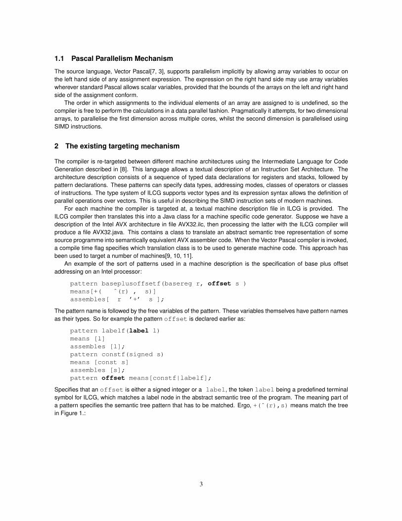
Specifies that an offset is either a signed integer or a label, the token label being a predefined terminalsymbol for ILCG, which matches a label node in the abstract semantic tree of the program. The meaning part ofa pattern specifies the semantic tree pattern that has to be matched. Ergo, +(ˆ(r),s) means match the treein Figure 1.:
3
dyad
+
^
monad
invoke basereg pattern
invoke offset pattern
Fig. 1: Example of an ILCG tree, in this case for +(ˆ(r),s).
A particular example of an ILCG expression this would match could be +( ˆ(regEBX),20). Note that ˆis the dereference operator.
Associated with each pattern there is a variable table that contains the current bindings of the local variables.This contains two rows, one for the tree that has been matched by a pattern variable and the other that containsthe equivalent assembler generated by the match.
r stree matched ˆ(regEBX) 20
assembler output ’ebx’ ’20’
The assembler output of a pattern is a string formed by concatenating any string literals with the assembleroutput of any local variables used in the assembler part of the pattern. The same variable can be used repeatedlyin a pattern. In this case the semantic tree for the second and subsequent uses of the variable must be identicalto its first/leftmost occurrence. For example in the pattern:
instruction patternRLIT0(nonmultoperator op, anyreg rm, type t, int sm)means[(ref t) rm:= op(ˆ(rm),(t) const sm) ]assembles[ op ’ ’ rm ’,’ sm ];
The variables t and rm are each used twice, ensuring that it would use the RLIT0 pattern for the expressionregBL:=+(ˆ(regBL),1)producing as output ’add bl,1’, but it would not allow the pattern to matchregEAX:=+(ˆ(regEBX),1)since a different register is used on the two halves of that tree.
3 Vectorisation
We decided to keep the front end of the Pascal compiler as machine independent as possible, whilst allowingthe maximum use of specialist instruction sets. The most important specialisation is the availability of SIMDinstructions over various types. Since not all machines support SIMD operations over all types, the front end canquery the code generator classes to discover what types are supported for SIMD and what the length of the SIMDregisters for these types are. Given an array assignment statement, the front end first generates the tree for ascalar for-loop to perform the requisite semantics. It then checks whether this is potentially vectorisable, and if itis, it checks if the code generator supports SIMD operations on the specified type. In the event that it does, thefront end then converts the scalar for-loop into a vectorised for loop before passing it to the back end for codegeneration.
The checks for vectorisability involve:
1. Excluding statements with function calls, e.g., a[i]:=ln(b[i]).
4
2. Excluding statements in which the loop iterator i is not used as the rightmost index of a multi-dimensionalarray, e.g., a[i]:=b[i,j].
3. Excluding statements in which the loop iterator i is multiplied by some factor, e.g., a[i]:=b[i*k].
4. Excluding statements in which the index of an array is another array, e.g., a[i]:=b[c[i]].
These were reasonable restrictions for the first and second generation of SIMD machines, but some of them areunnecessary for more modern machines such as the XeonPhi. In particular the availability of gather instructionsmeans that we do not need to be so restrictive in the forms of access that can be vectorised. One can envisageother machines being built that will allow at least certain functions to be performed in SIMD form.
3.1 Vectorisation Solutions
Rather than be faced with the need to have complex machine specific tests and tree transformations in the frontend, it was decided to keep a common front end and extend the semantic power of the specification language. Thisallows the machine specification to describe the sorts of tree transformations that may be needed for vectorisation.Previously ILCG simply performed pattern matching to transform trees into assembler strings. Now it has beenupgraded to allow tree → tree transformations before these are mapped into assembler strings.
The extensions made to the ILCG machine description language are:
• Patterns can now be recursive.
• It is possible to invoke a pattern using a parameter passing mechanism that allows pattern variables to bepre-bound.
• Transformer patterns can be defined. Such patterns output a new semantic tree rather than an assemblerstring.
• Pattern matching can be made conditional on predicates.
As a first illustration let us look at a pattern that will vectorise for loops on the XeonPhi:
transformer pattern vectorisablefor (any i,any start,any finish,vecdest lhs,vectorisablalternatives rhs)
means[for (ref int32)i:=startto finishstep 1 do lhs[i] := rhs[i]
]returns[
statement(for i.in:=+(+(-(*(div(
+(1,-(finish.in,start.in)),16),16),1),start.in),1)
to finish.instep 1 do lhs.in := rhs.in ,for i.in:= start.into +(-(*(div(
+(1,-(finish.in,start.in)),16),16),1),start.in)
step 16 do lhs.out:=rhs.out
5
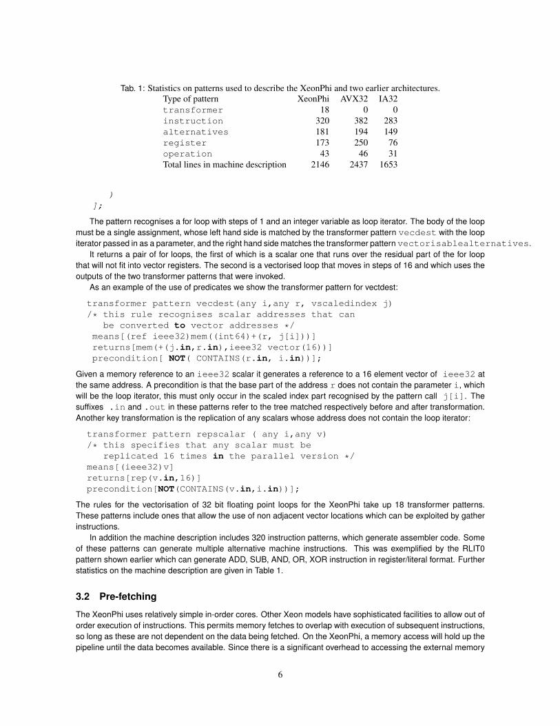
Tab. 1: Statistics on patterns used to describe the XeonPhi and two earlier architectures.Type of pattern XeonPhi AVX32 IA32transformer 18 0 0instruction 320 382 283alternatives 181 194 149register 173 250 76operation 43 46 31Total lines in machine description 2146 2437 1653
)];
The pattern recognises a for loop with steps of 1 and an integer variable as loop iterator. The body of the loopmust be a single assignment, whose left hand side is matched by the transformer pattern vecdest with the loopiterator passed in as a parameter, and the right hand side matches the transformer pattern vectorisablealternatives.
It returns a pair of for loops, the first of which is a scalar one that runs over the residual part of the for loopthat will not fit into vector registers. The second is a vectorised loop that moves in steps of 16 and which uses theoutputs of the two transformer patterns that were invoked.
As an example of the use of predicates we show the transformer pattern for vectdest:
transformer pattern vecdest(any i,any r, vscaledindex j)/* this rule recognises scalar addresses that can
be converted to vector addresses */means[(ref ieee32)mem((int64)+(r, j[i]))]returns[mem(+(j.in,r.in),ieee32 vector(16))]precondition[ NOT( CONTAINS(r.in, i.in))];
Given a memory reference to an ieee32 scalar it generates a reference to a 16 element vector of ieee32 atthe same address. A precondition is that the base part of the address r does not contain the parameter i, whichwill be the loop iterator, this must only occur in the scaled index part recognised by the pattern call j[i]. Thesuffixes .in and .out in these patterns refer to the tree matched respectively before and after transformation.Another key transformation is the replication of any scalars whose address does not contain the loop iterator:
transformer pattern repscalar ( any i,any v)/* this specifies that any scalar must be
replicated 16 times in the parallel version */means[(ieee32)v]returns[rep(v.in,16)]precondition[NOT(CONTAINS(v.in,i.in))];
The rules for the vectorisation of 32 bit floating point loops for the XeonPhi take up 18 transformer patterns.These patterns include ones that allow the use of non adjacent vector locations which can be exploited by gatherinstructions.
In addition the machine description includes 320 instruction patterns, which generate assembler code. Someof these patterns can generate multiple alternative machine instructions. This was exemplified by the RLIT0pattern shown earlier which can generate ADD, SUB, AND, OR, XOR instruction in register/literal format. Furtherstatistics on the machine description are given in Table 1.
3.2 Pre-fetching
The XeonPhi uses relatively simple in-order cores. Other Xeon models have sophisticated facilities to allow out oforder execution of instructions. This permits memory fetches to overlap with execution of subsequent instructions,so long as these are not dependent on the data being fetched. On the XeonPhi, a memory access will hold up thepipeline until the data becomes available. Since there is a significant overhead to accessing the external memory
6
tag line sel xxxxxx
=
64 bits
64 bytes
DATA LINESTAG LINES
EFFECTIVE ADDRESS 6 DONT CARE BITS
l0l1l2l3l4
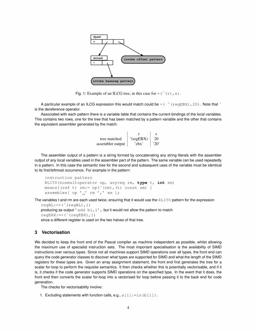
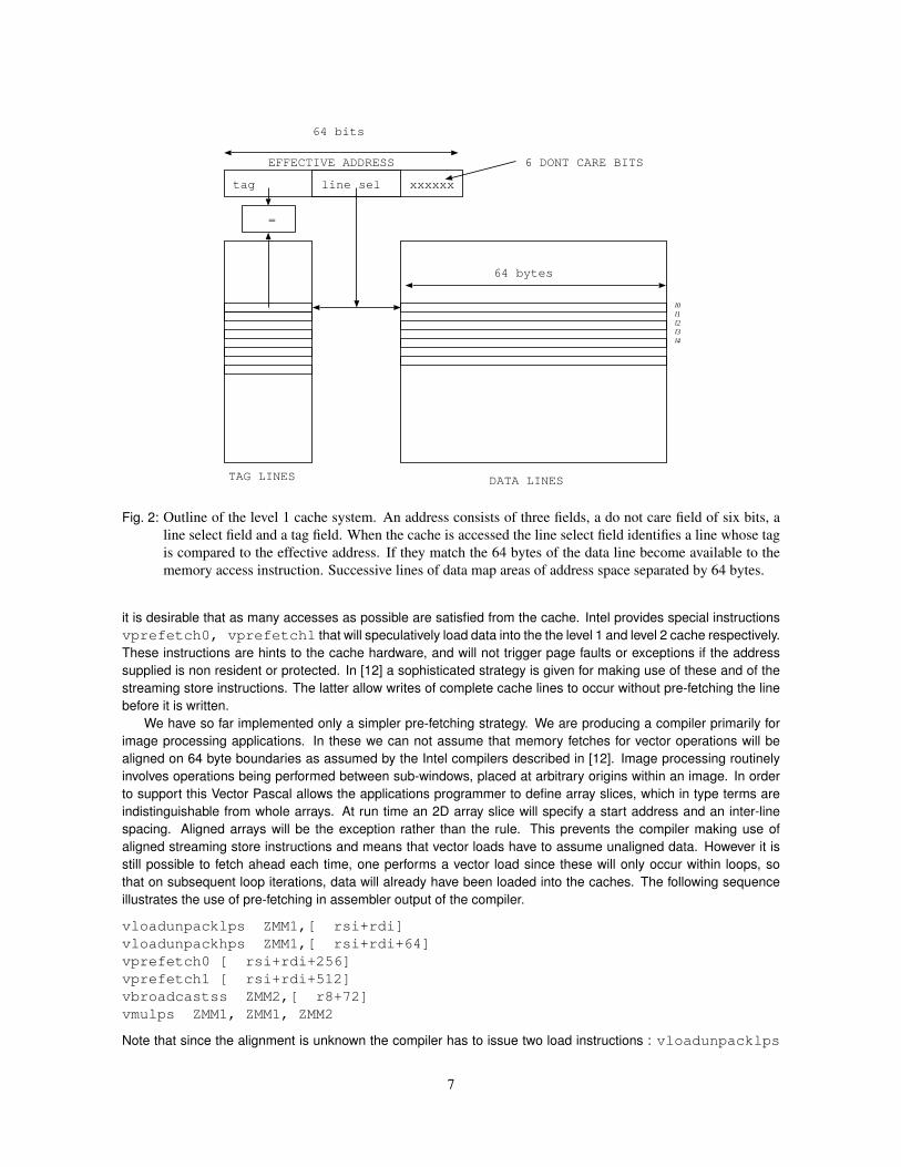
Fig. 2: Outline of the level 1 cache system. An address consists of three fields, a do not care field of six bits, aline select field and a tag field. When the cache is accessed the line select field identifies a line whose tagis compared to the effective address. If they match the 64 bytes of the data line become available to thememory access instruction. Successive lines of data map areas of address space separated by 64 bytes.
it is desirable that as many accesses as possible are satisfied from the cache. Intel provides special instructionsvprefetch0, vprefetch1 that will speculatively load data into the the level 1 and level 2 cache respectively.These instructions are hints to the cache hardware, and will not trigger page faults or exceptions if the addresssupplied is non resident or protected. In [12] a sophisticated strategy is given for making use of these and of thestreaming store instructions. The latter allow writes of complete cache lines to occur without pre-fetching the linebefore it is written.
We have so far implemented only a simpler pre-fetching strategy. We are producing a compiler primarily forimage processing applications. In these we can not assume that memory fetches for vector operations will bealigned on 64 byte boundaries as assumed by the Intel compilers described in [12]. Image processing routinelyinvolves operations being performed between sub-windows, placed at arbitrary origins within an image. In orderto support this Vector Pascal allows the applications programmer to define array slices, which in type terms areindistinguishable from whole arrays. At run time an 2D array slice will specify a start address and an inter-linespacing. Aligned arrays will be the exception rather than the rule. This prevents the compiler making use ofaligned streaming store instructions and means that vector loads have to assume unaligned data. However it isstill possible to fetch ahead each time, one performs a vector load since these will only occur within loops, sothat on subsequent loop iterations, data will already have been loaded into the caches. The following sequenceillustrates the use of pre-fetching in assembler output of the compiler.
vloadunpacklps ZMM1,[ rsi+rdi]vloadunpackhps ZMM1,[ rsi+rdi+64]vprefetch0 [ rsi+rdi+256]vprefetch1 [ rsi+rdi+512]vbroadcastss ZMM2,[ r8+72]vmulps ZMM1, ZMM1, ZMM2
Note that since the alignment is unknown the compiler has to issue two load instructions : vloadunpacklps
7
followed by vloadunpackhps to load into vector register ZMM1 the low and high portions of a 16 float vector(64 bytes) from two successive 64 byte cache lines. This explicit exposure of the cache lines in the instruction setarchitecture is a new feature for Intel. In previous Intel instruction sets, a data transfer that potentially spanned twocache lines could be performed in a single instruction. For clarification see Figure 2. Let us call the lines accessedby the vloadunpack instructions: l0 and l1.
It then issues a prefetch for line l4 into the level 1 cache, and a prefetch for l8 into the level 2 cache. The fetchfor line l4 is 4× 64 = 256 bytes on from the original effective address specified by the sum of rsi and rdi. Theintention is that by the time 4 iterations of the loop have been performed the data for the next iteration will havebeen preloaded into the level 1 cache.
In the following line a scalar floating point variable is loaded and replicated into all 16 locations in vector registerZMM2, before this is multiplied with ZMM1. This code is generated as part of an expression that multiplies a twodimensional array slice with a constant.
4 Glasgow Vector Pascal performance tests
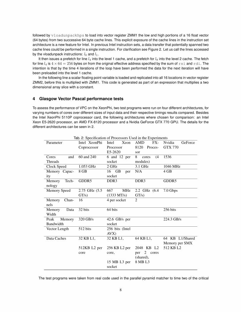
To assess the performance of VPC on the XeonPhi, two test programs were run on four different architectures, forvarying numbers of cores over different sizes of input data and their respective timings results compared. Besidesthe Intel XeonPhi 5110P coprocessor card, the following architectures where chosen for comparison: an IntelXeon E5-2620 processor, an AMD FX-8120 processor and a Nvidia GeForce GTX 770 GPU. The details for thedifferent architectures can be seen in 2.
Tab. 2: Specification of Processors Used in the ExperimentsParameter Intel XeonPhi
CoprocessorIntel XeonProcessorE5-2620
AMD FX-8120 Proces-sor
Nvidia GeForceGTX 770
Cores andThreads
60 and 240 6 and 12 persocket
8 cores (4modules)
1536
Clock Speed 1.053 GHz 2 GHz 3.1 GHz 1046 MHzMemory Capac-ity
8 GB 16 GB persocket
N/A 4 GB
Memory Tech-nology
GDDR5 DDR3 DDR3 GDDR5
Memory Speed 2.75 GHz (5.5GT/s)
667 MHz(1333 MT/s)
2.2 GHz (6.4GT/s)
7.0 Gbps
Memory Chan-nels
16 4 per socket 2
Memory DataWidth
32 bits 64 bits 256 bits
Peak MemoryBandwidth
320 GB/s 42.6 GB/s persocket
224.3 GB/s
Vector Length 512 bits 256 bits (IntelAVX)
Data Caches 32 KB L1, 32 KB L1, 64 KB L1, 64 KB L1/SharedMemory per SMX
512KB L2 percore
256 KB L2 percore,
2048 KB L2per 2 cores(shared),
512 KB L2
15 MB L3 persocket
8 MB L3
The test programs were taken from real code used in the parallel pyramid matcher to time two of the critical
8
10 100
number of threads used
1
10
100
Mill
ese
conds
per
image
convolve using semaphores
convolve using busy wait
scale using semaphores
scale using busy wait
Scaling and convolving 1152 sq images on Xeon Phi
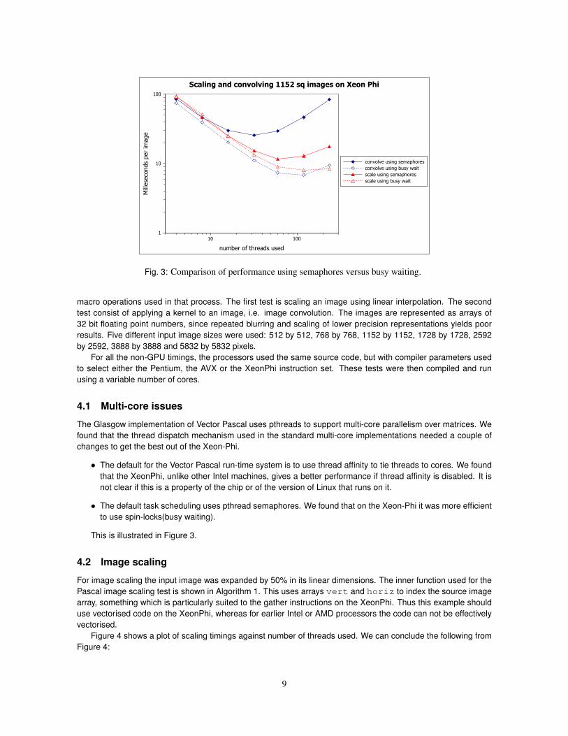
Fig. 3: Comparison of performance using semaphores versus busy waiting.
macro operations used in that process. The first test is scaling an image using linear interpolation. The secondtest consist of applying a kernel to an image, i.e. image convolution. The images are represented as arrays of32 bit floating point numbers, since repeated blurring and scaling of lower precision representations yields poorresults. Five different input image sizes were used: 512 by 512, 768 by 768, 1152 by 1152, 1728 by 1728, 2592by 2592, 3888 by 3888 and 5832 by 5832 pixels.
For all the non-GPU timings, the processors used the same source code, but with compiler parameters usedto select either the Pentium, the AVX or the XeonPhi instruction set. These tests were then compiled and runusing a variable number of cores.
4.1 Multi-core issues
The Glasgow implementation of Vector Pascal uses pthreads to support multi-core parallelism over matrices. Wefound that the thread dispatch mechanism used in the standard multi-core implementations needed a couple ofchanges to get the best out of the Xeon-Phi.
• The default for the Vector Pascal run-time system is to use thread affinity to tie threads to cores. We foundthat the XeonPhi, unlike other Intel machines, gives a better performance if thread affinity is disabled. It isnot clear if this is a property of the chip or of the version of Linux that runs on it.
• The default task scheduling uses pthread semaphores. We found that on the Xeon-Phi it was more efficientto use spin-locks(busy waiting).
This is illustrated in Figure 3.
4.2 Image scaling
For image scaling the input image was expanded by 50% in its linear dimensions. The inner function used for thePascal image scaling test is shown in Algorithm 1. This uses arrays vert and horiz to index the source imagearray, something which is particularly suited to the gather instructions on the XeonPhi. Thus this example shoulduse vectorised code on the XeonPhi, whereas for earlier Intel or AMD processors the code can not be effectivelyvectorised.
Figure 4 shows a plot of scaling timings against number of threads used. We can conclude the following fromFigure 4:
9
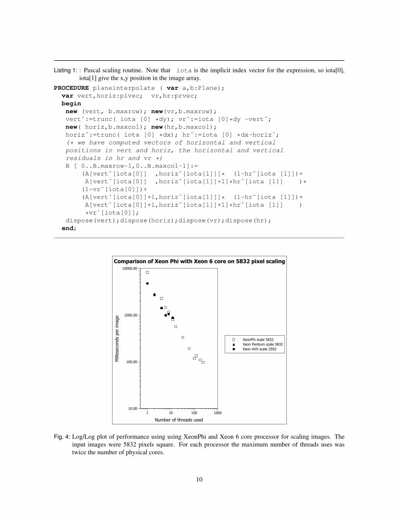
Listing 1: : Pascal scaling routine. Note that iota is the implicit index vector for the expression, so iota[0],iota[1] give the x,y position in the image array.
PROCEDURE planeinterpolate ( var a,b:Plane);var vert,horiz:pivec; vr,hr:prvec;beginnew (vert, b.maxrow); new(vr,b.maxrow);vertˆ:=trunc( iota [0] *dy); vrˆ:=iota [0]*dy -vertˆ;new( horiz,b.maxcol); new(hr,b.maxcol);horizˆ:=trunc( iota [0] *dx); hrˆ:=iota [0] *dx-horizˆ;(* we have computed vectors of horizontal and verticalpositions in vert and horiz, the horizontal and verticalresiduals in hr and vr *)B [ 0..B.maxrow-1,0..B.maxcol-1]:=
(A[vertˆ[iota[0]] ,horizˆ[iota[1]]]* (1-hrˆ[iota [1]])+A[vertˆ[iota[0]] ,horizˆ[iota[1]]+1]*hrˆ[iota [1]] )*
(1-vrˆ[iota[0]])+(A[vertˆ[iota[0]]+1,horizˆ[iota[1]]]* (1-hrˆ[iota [1]])+A[vertˆ[iota[0]]+1,horizˆ[iota[1]]+1]*hrˆ[iota [1]] )
*vrˆ[iota[0]];dispose(vert);dispose(horiz);dispose(vr);dispose(hr);
end;
1 10 100 1000
Number of threads used
10.00
100.00
1000.00
10000.00
Mill
ese
conds
per
image
XeonPhi scale 5832
Xeon Pentium scale 5832
Xeon AVX scale 2592
Comparison of Xeon Phi with Xeon 6 core on 5832 pixel scaling
Fig. 4: Log/Log plot of performance using using XeonPhi and Xeon 6 core processor for scaling images. Theinput images were 5832 pixels square. For each processor the maximum number of threads uses wastwice the number of physical cores.
10
Tab. 3: Ratio of XeonPhi to Ivybridge Xeon speeds for different image sizes. 12 threads on Xeon compared to100 threads on XeonPhi. Numbers > 1 indicate that the XeonPhi is faster.
Image size Scaling Convolution512x512 3.8 0.6768x768 4.3 0.8
1152x1152 4.9 1.31728x1728 5.6 1.82592x2592 6.1 1.33888x3888 6.6 1.05832x5832 7.5 1.2
• When using the same number of threads on a large image the Ivybridge Xeon host processor outperformsthe XeonPhi on scaling.
• The XeonPhi however, overtakes the host Xeon once the number of threads is greater than 10. It goes onto achieve a peak performance an order of magnitude greater than the host Xeon.
• The XeonPhi supports hyperthreading and shows a modest performance gain above 60 threads, but thisgain is not monotonic, there is a local minimum of time at 100 threads with a local maximum at 120 threads.
Scaling images allows use of the XeonPhi gather instructions. It is a particularly favourable basis on which tocompare the XeonPhi with standard Xeons. Table 3 shows that the performance gain on scaling ranges from 3.2to 5.5.
4.3 Image convolution
Convolution of an image by a matrix of real numbers can be used to smooth or sharpen an image, depending onthe matrix used. If A is an output image, K a convolution matrix, then if B is the convolved image
By,x =∑i
∑j
Ay+i,x+jKi,j
A separable convolution kernel is a vector of real numbers that can be applied independently to the rowsand columns of an image to provide filtering. It is a specialisation of the more general convolution matrix, but isalgorithmically more efficient to implement.
If k is a convolution vector, then the corresponding matrix K is such that Ki,j = kikj .Given a starting image A as a two dimensional array of pixels, and a three element kernel c1, c2, c3, the
algorithm first forms a temporary array T whose whose elements are the weighted sum of adjacent rows Ty,x =c1Ay−1,x + c2Ay,x + c3Ay+1,x. Then in a second phase it sets the original image to be the weighted sum of thecolumns of the temporary array: Ay,x = c1Ty,x−1 + c2Ty,x + c3Ty, x+ 1.
Clearly the outer edges of the image are a special case, since the convolution is defined over the neighboursof the pixel, and the pixels along the boundaries a missing one neighbour. A number of solutions are availablefor this, but for simplicity we will perform only vertical convolutions on the left and right edges and horizontalconvolutions on the top and bottom lines of the image. Below we show the algorithm used in Pascal for theparallel convolution of images. Most of the work is done by the function MA5 which assigns to the output imageplane acc the sum of the input planes p1 to p5 weighted by the elements of the kernel k;
PROCEDURE MA5(VAR acc, p1,p2,p3,p4,p5:plane;k:kernel);BEGIN
acc:= p1* k[1] +p2*k[2] +p3*k[3] +p4*k[4]+p5*k[5];END;
The next procedure convolves a plane by applying the vertical and horizontal convolutions in turn.The writetopand writebottom flags indicate if the top and bottom margins are to be written or ignored.
11
PROCEDURE convp(VAR p,T:plane; writetop,writebottom:boolean);VAR r,c,k,i,lo,hi,bm,tm,mid,l:integer;BEGIN
This sequence performs a vertical convolution of the rows of the plane p and places the result in the temporaryplane T . On successive calls to MA5 the procedure is passed first a set of vertical subplanes offset by one row,and then a set of horizontal subplanes offset by one column.
margin:=(kernel_size div 2);(* margin specifies how many rows at top and bottomare left out *)r:=p.rows; lo := margin; hi:=r-margin;MA5(T [lo..hi],p[0..hi-lo+0],p[1..hi-lo+1],p[2..hi-lo+2],
p[3..hi-lo+3],p[4..hi-lo+4],kerr)l:=margin -1;if l> T.rows then l:= t.rows;for k:=0 to l do BEGIN (* handle top and bottom margin *)
T[k]:=p[k];T[r-k]:=p[r-k];
END ;p:=T;
Now perform a horizontal convolution of the plane T and place the result in p.
c:=p.cols; hi:= c-margin;bm:=0;tm:=r;if not writetop then bm:=margin;if not writebottom then tm:=r-margin;MA5(p [bm..tm,lo..hi],t[bm..tm,0..hi-lo+0],
t[bm..tm,1..hi-lo+1], t[bm..tm,2..hi-lo+2],t[bm..tm,3..hi-lo+3],t[bm..tm,4..hi-lo+4], kerr)
for k:=0 to margin-1 do BEGIN (* left and right margin *)p[bm..tm,k]:=T[bm..tm,k];p[bm..tm,c-k]:=T[bm..tm,c-k];
END ;END ;
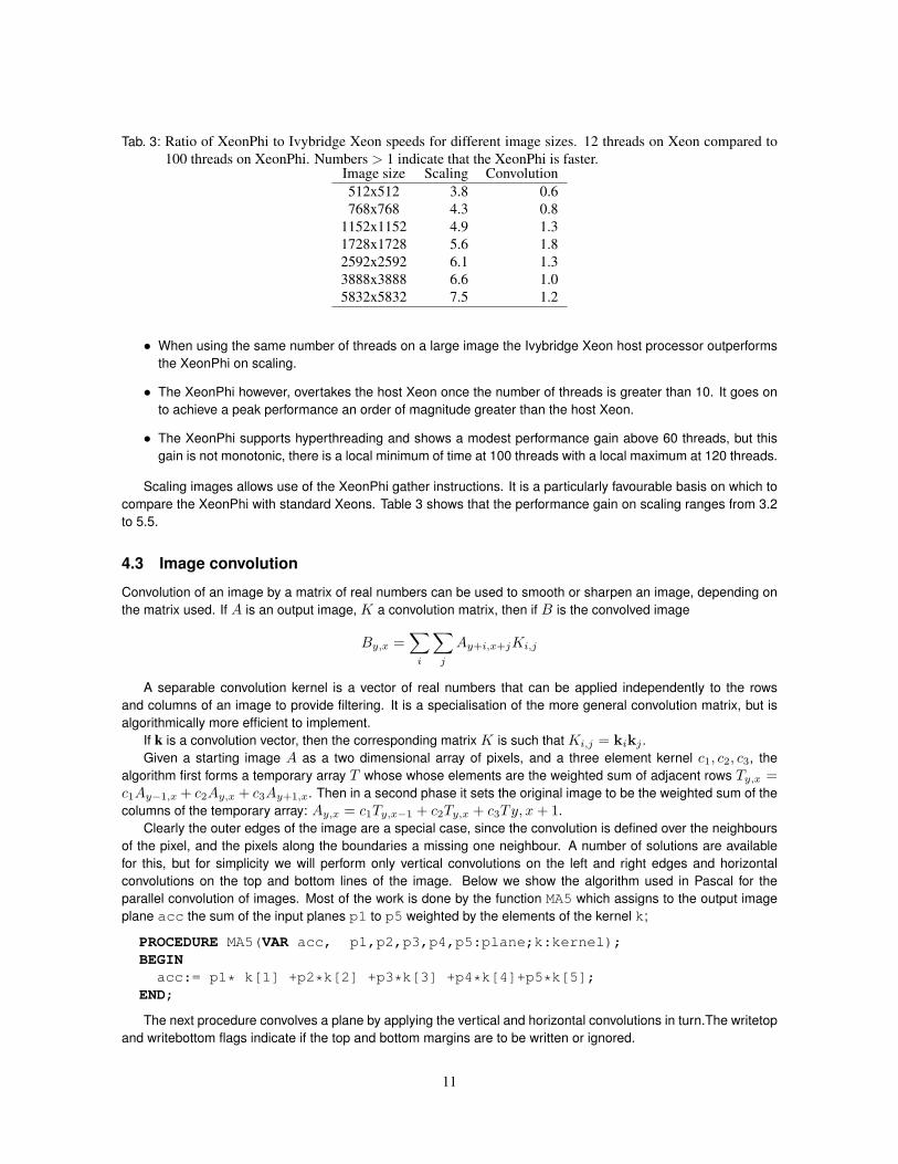
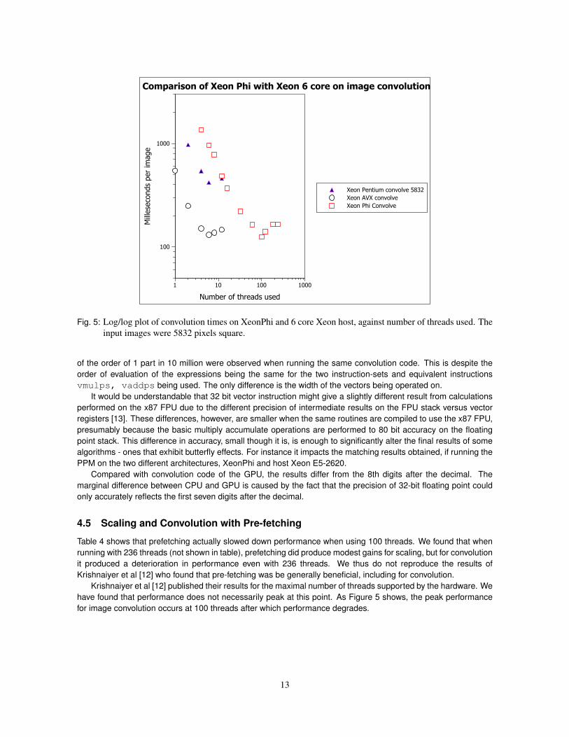
On image convolution, an operation that can be vectorised well on either and AVX or a Phi instruction set, theperformance gain of the Xeon Phi is much more modest than it was for resizing.
If we contrast Figure 4 with Figure 5 we see that the XeonPhi performs worse core for core as compared to theXeon using vectorised AVX code and the Xeon running scalar Pentium instruction-set code. Even at the optimalnumber of threads (100) the XeonPhi only slightly outperforms the host processor.
The machines were running the same source code, processed by the same compiler front ends. However,the XeonPhi code is taking advantage of 16 way vectorisation against the 8 way vectorisation on the ordinaryXeon. Against this the XeonPhi runs at half the clock speed of the Xeon and is 4 way hyper-threaded verses 2way hyper-threaded on the Xeon. A worst case scenario would thus be that a thread on the Xeon would execute4 clock cycles for every one clock cycle executed by a thread on the XeonPhi. On top of this the XeonPhi core issimpler and has less sophisticated super-scalar features than the Ivybridge Xeon.
We had expected the relative advantage to be greater in the case of image scaling since for this task theXeonPhi can use gather instructions, which are not available on the ordinary Xeon.
4.4 Accuracy issues
During the convolution experiments it was noted that the 32 bit floating point hardware on the MIC did not giveidentical results when compared to the host Xeon using AVX 32 bit vector instructions. Divergences in the results
12
1 10 100 1000
Number of threads used
100
1000M
illese
conds
per
image
Xeon Pentium convolve 5832
Xeon AVX convolve
Xeon Phi Convolve
Comparison of Xeon Phi with Xeon 6 core on image convolution
Fig. 5: Log/log plot of convolution times on XeonPhi and 6 core Xeon host, against number of threads used. Theinput images were 5832 pixels square.
of the order of 1 part in 10 million were observed when running the same convolution code. This is despite theorder of evaluation of the expressions being the same for the two instruction-sets and equivalent instructionsvmulps, vaddps being used. The only difference is the width of the vectors being operated on.
It would be understandable that 32 bit vector instruction might give a slightly different result from calculationsperformed on the x87 FPU due to the different precision of intermediate results on the FPU stack versus vectorregisters [13]. These differences, however, are smaller when the same routines are compiled to use the x87 FPU,presumably because the basic multiply accumulate operations are performed to 80 bit accuracy on the floatingpoint stack. This difference in accuracy, small though it is, is enough to significantly alter the final results of somealgorithms - ones that exhibit butterfly effects. For instance it impacts the matching results obtained, if running thePPM on the two different architectures, XeonPhi and host Xeon E5-2620.
Compared with convolution code of the GPU, the results differ from the 8th digits after the decimal. Themarginal difference between CPU and GPU is caused by the fact that the precision of 32-bit floating point couldonly accurately reflects the first seven digits after the decimal.
4.5 Scaling and Convolution with Pre-fetching
Table 4 shows that prefetching actually slowed down performance when using 100 threads. We found that whenrunning with 236 threads (not shown in table), prefetching did produce modest gains for scaling, but for convolutionit produced a deterioration in performance even with 236 threads. We thus do not reproduce the results ofKrishnaiyer et al [12] who found that pre-fetching was be generally beneficial, including for convolution.
Krishnaiyer et al [12] published their results for the maximal number of threads supported by the hardware. Wehave found that performance does not necessarily peak at this point. As Figure 5 shows, the peak performancefor image convolution occurs at 100 threads after which performance degrades.
13
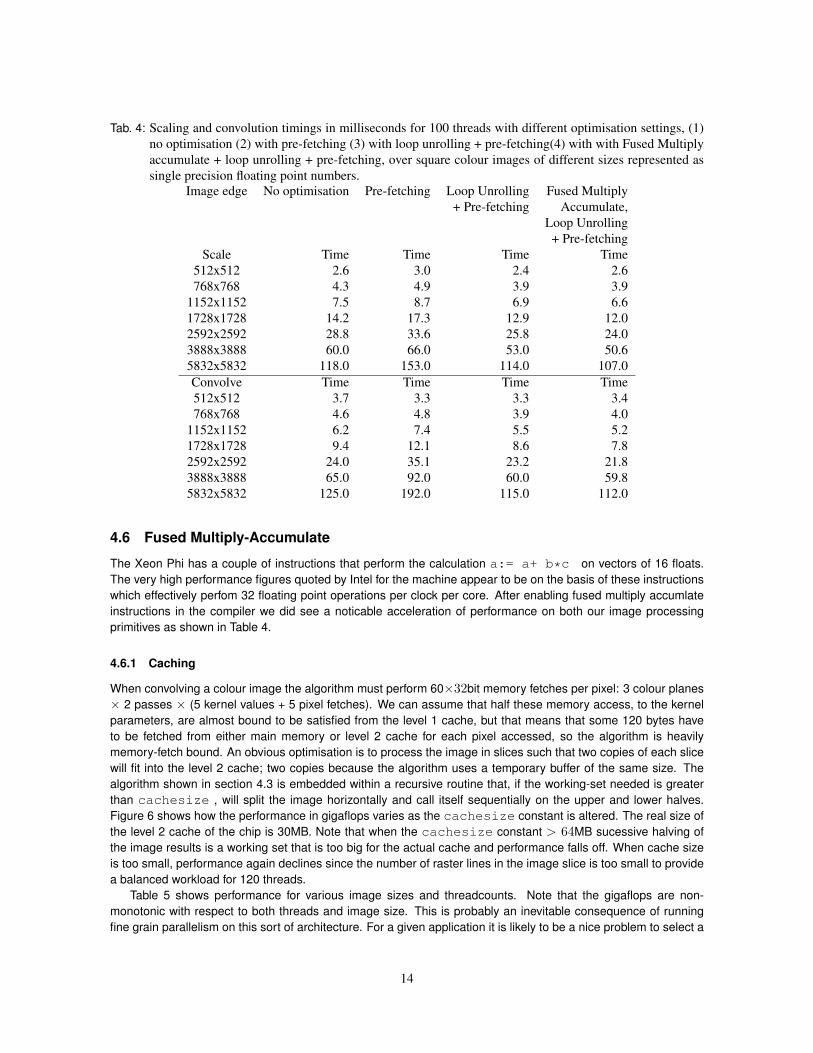
Tab. 4: Scaling and convolution timings in milliseconds for 100 threads with different optimisation settings, (1)no optimisation (2) with pre-fetching (3) with loop unrolling + pre-fetching(4) with with Fused Multiplyaccumulate + loop unrolling + pre-fetching, over square colour images of different sizes represented assingle precision floating point numbers.
Image edge No optimisation Pre-fetching Loop Unrolling Fused Multiply+ Pre-fetching Accumulate,
Loop Unrolling+ Pre-fetching
Scale Time Time Time Time512x512 2.6 3.0 2.4 2.6768x768 4.3 4.9 3.9 3.9
1152x1152 7.5 8.7 6.9 6.61728x1728 14.2 17.3 12.9 12.02592x2592 28.8 33.6 25.8 24.03888x3888 60.0 66.0 53.0 50.65832x5832 118.0 153.0 114.0 107.0Convolve Time Time Time Time512x512 3.7 3.3 3.3 3.4768x768 4.6 4.8 3.9 4.0
1152x1152 6.2 7.4 5.5 5.21728x1728 9.4 12.1 8.6 7.82592x2592 24.0 35.1 23.2 21.83888x3888 65.0 92.0 60.0 59.85832x5832 125.0 192.0 115.0 112.0
4.6 Fused Multiply-Accumulate
The Xeon Phi has a couple of instructions that perform the calculation a:= a+ b*c on vectors of 16 floats.The very high performance figures quoted by Intel for the machine appear to be on the basis of these instructionswhich effectively perfom 32 floating point operations per clock per core. After enabling fused multiply accumlateinstructions in the compiler we did see a noticable acceleration of performance on both our image processingprimitives as shown in Table 4.
4.6.1 Caching
When convolving a colour image the algorithm must perform 60×32bit memory fetches per pixel: 3 colour planes× 2 passes × (5 kernel values + 5 pixel fetches). We can assume that half these memory access, to the kernelparameters, are almost bound to be satisfied from the level 1 cache, but that means that some 120 bytes haveto be fetched from either main memory or level 2 cache for each pixel accessed, so the algorithm is heavilymemory-fetch bound. An obvious optimisation is to process the image in slices such that two copies of each slicewill fit into the level 2 cache; two copies because the algorithm uses a temporary buffer of the same size. Thealgorithm shown in section 4.3 is embedded within a recursive routine that, if the working-set needed is greaterthan cachesize , will split the image horizontally and call itself sequentially on the upper and lower halves.Figure 6 shows how the performance in gigaflops varies as the cachesize constant is altered. The real size ofthe level 2 cache of the chip is 30MB. Note that when the cachesize constant > 64MB sucessive halving ofthe image results is a working set that is too big for the actual cache and performance falls off. When cache sizeis too small, performance again declines since the number of raster lines in the image slice is too small to providea balanced workload for 120 threads.
Table 5 shows performance for various image sizes and threadcounts. Note that the gigaflops are non-monotonic with respect to both threads and image size. This is probably an inevitable consequence of runningfine grain parallelism on this sort of architecture. For a given application it is likely to be a nice problem to select a
14
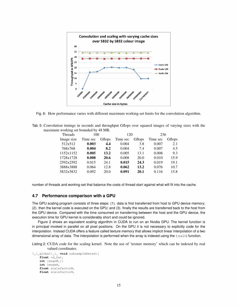
Fig. 6: How performance varies with different maximum working-set limits for the convolution algorithm.
Tab. 5: Convolution timings in seconds and throughput Gflops over squared images of varying sizes with themaximum working set bounded by 48 MB.
Threads 100 120 236Image size Time sec Gflops Time sec Gflops Time sec Gflops512x512 0.003 4.4 0.004 3.8 0.007 2.1768x768 0.004 8.2 0.004 7.4 0.007 4.5
1152x1152 0.005 13.2 0.005 13.1 0.008 9.31728x1728 0.008 20.6 0.008 20.0 0.010 15.92592x2592 0.015 24.1 0.015 24.3 0.019 19.13888x3888 0.064 12.8 0.062 13.2 0.076 10.75832x5832 0.092 20.0 0.091 20.1 0.116 15.8
number of threads and working-set that balance the costs of thread start against what will fit into the cache.
4.7 Performance comparison with a GPU
The GPU scaling program consists of three steps: (1). data is first transferred from host to GPU device memory;(2). then the kernel code is executed on the GPU; and (3). finally the results are transferred back to the host fromthe GPU device. Compared with the time consumed on transferring between the host and the GPU device, theexecution time for GPU kernel is considerably short and could be ignored.
Figure 2 shows an equivalent scaling algorithm in CUDA to run on an Nvidia GPU. The kernel function isin principal invoked in parallel on all pixel positions. On the GPU it is not necessary to explicitly code for theinterpolation. Instead CUDA offers a feature called texture memory that allows implicit linear interpolation of a twodimensional array of data. The interpolation is performed when the array is indexed using the tex2d function.
Listing 2: CUDA code for the scaling kernel. Note the use of ’texture memory’ which can be indexed by realvalued coordinates.
\_\_global\_\_ void subsampleKernel(float *d_Dst,int imageW,]{int imageH,float scalefactorW,float scalefactorH,
15
int imageW2,int imageH2
){
const int ix = IMAD(blockDim.x, blockIdx.x, threadIdx.x);const int iy = IMAD(blockDim.y, blockIdx.y, threadIdx.y);const float x = (float)ix + 0.5f;const float y = (float)iy + 0.5f;if (ix >= imageW2 || iy >= imageH2){
return;}d_Dst[IMAD(iy, imageW2, ix)] = tex2D(texSrc, x / scalefactorW,
y / scalefactorH);}
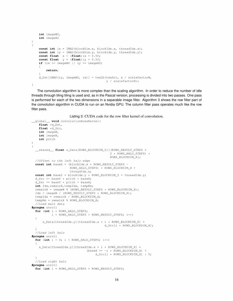
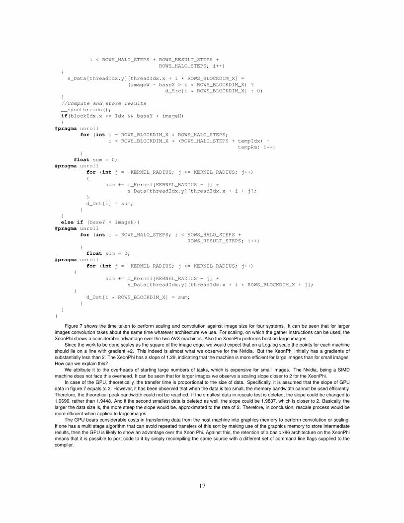
The convolution algorithm is more complex than the scaling algorithm. In order to reduce the number of idlethreads through tiling tiling is used and, as in the Pascal version, processing is divided into two passes. One passis performed for each of the two dimensions in a separable image filter. Algorithm 3 shows the row filter part ofthe convolution algorithm in CUDA to run on an Nvidia GPU. The column filter pass operates much like the rowfilter pass.
Listing 3: CUDA code for the row filter kernel of convolution.__global__ void convolutionRowsKernel(
float *d_Dst,float *d_Src,int imageW,int imageH,int pitch
){__shared__ float s_Data[ROWS_BLOCKDIM_Y][(ROWS_RESULT_STEPS +
2 * ROWS_HALO_STEPS) *ROWS_BLOCKDIM_X];
//Offset to the left halo edgeconst int baseX = (blockIdx.x * ROWS_RESULT_STEPS -
ROWS_HALO_STEPS) * ROWS_BLOCKDIM_X +threadIdx.x;
const int baseY = blockIdx.y * ROWS_BLOCKDIM_Y + threadIdx.y;d_Src += baseY * pitch + baseX;d_Dst += baseY * pitch + baseX;int Idx,remainX,tempIdx, tempRm;remainX = imageW % (ROWS_RESULT_STEPS * ROWS_BLOCKDIM_X);Idx = imageW / (ROWS_RESULT_STEPS * ROWS_BLOCKDIM_X);tempIdx = remainX / ROWS_BLOCKDIM_X;tempRm = remainX % ROWS_BLOCKDIM_X;//Load main data
#pragma unrollfor (int i = ROWS_HALO_STEPS;
i < ROWS_HALO_STEPS + ROWS_RESULT_STEPS; i++){
s_Data[threadIdx.y][threadIdx.x + i * ROWS_BLOCKDIM_X] =d_Src[i * ROWS_BLOCKDIM_X];
}//Load left halo
#pragma unrollfor (int i = 0; i < ROWS_HALO_STEPS; i++){
s_Data[threadIdx.y][threadIdx.x + i * ROWS_BLOCKDIM_X] =(baseX >= -i * ROWS_BLOCKDIM_X) ?
d_Src[i * ROWS_BLOCKDIM_X] : 0;}//Load right halo
#pragma unrollfor (int i = ROWS_HALO_STEPS + ROWS_RESULT_STEPS;
16
i < ROWS_HALO_STEPS + ROWS_RESULT_STEPS +ROWS_HALO_STEPS; i++)
{s_Data[threadIdx.y][threadIdx.x + i * ROWS_BLOCKDIM_X] =
(imageW - baseX > i * ROWS_BLOCKDIM_X) ?d_Src[i * ROWS_BLOCKDIM_X] : 0;
}//Compute and store results__syncthreads();if(blockIdx.x >= Idx && baseY < imageH){
#pragma unrollfor (int i = ROWS_BLOCKDIM_X * ROWS_HALO_STEPS;
i < ROWS_BLOCKDIM_X * (ROWS_HALO_STEPS + tempIdx) +tempRm; i++)
{float sum = 0;
#pragma unrollfor (int j = -KERNEL_RADIUS; j <= KERNEL_RADIUS; j++){
sum += c_Kernel[KERNEL_RADIUS - j] *s_Data[threadIdx.y][threadIdx.x + i + j];
}d_Dst[i] = sum;
}}else if (baseY < imageH){
#pragma unrollfor (int i = ROWS_HALO_STEPS; i < ROWS_HALO_STEPS +
ROWS_RESULT_STEPS; i++){float sum = 0;
#pragma unrollfor (int j = -KERNEL_RADIUS; j <= KERNEL_RADIUS; j++)
{sum += c_Kernel[KERNEL_RADIUS - j] *
s_Data[threadIdx.y][threadIdx.x + i * ROWS_BLOCKDIM_X + j];}
d_Dst[i * ROWS_BLOCKDIM_X] = sum;}
}}
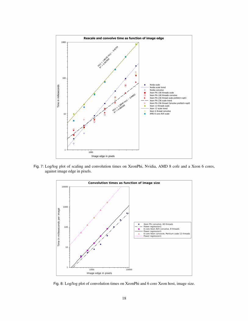
Figure 7 shows the time taken to perform scaling and convolution against image size for four systems. It can be seen that for largerimages convolution takes about the same time whatever architecture we use. For scaling, on which the gather instructions can be used, theXeonPhi shows a considerable advantage over the two AVX machines. Also the XeonPhi performs best on large images.
Since the work to be done scales as the square of the image edge, we would expect that on a Log/log scale the points for each machineshould lie on a line with gradient +2. This indeed is almost what we observe for the Nvidia. But the XeonPhi initially has a gradients ofsubstantially less than 2. The XeonPhi has a slope of 1.28, indicating that the machine is more efficient for large images than for small images.How can we explain this?
We attribute it to the overheads of starting large numbers of tasks, which is expensive for small images. The Nvidia, being a SIMDmachine does not face this overhead. It can be seen that for larger images we observe a scaling slope closer to 2 for the XeonPhi.
In case of the GPU, theoretically, the transfer time is proportional to the size of data. Specifically, it is assumed that the slope of GPUdata in figure 7 equals to 2. However, it has been observed that when the data is too small, the memory bandwidth cannot be used efficiently.Therefore, the theoretical peak bandwidth could not be reached. If the smallest data in rescale test is deleted, the slope could be changed to1.9696, rather than 1.9448. And if the second smallest data is deleted as well, the slope could be 1.9837, which is closer to 2. Basically, thelarger the data size is, the more steep the slope would be, approximated to the rate of 2. Therefore, in conclusion, rescale process would bemore efficient when applied to large images.
The GPU bears considerable costs in transferring data from the host machine into graphics memory to perform convolution or scaling.If one has a multi stage algorithm that can avoid repeated transfers of this sort by making use of the graphics memory to store intermediateresults, then the GPU is likely to show an advantage over the Xeon Phi. Against this, the retention of a basic x86 architecture on the XeonPhimeans that it is possible to port code to it by simply recompiling the same source with a different set of command line flags supplied to thecompiler.
17
1000
Image edge in pixels
1
10
100
1000
Tim
e in m
illese
conds
ln(y)
= 1
.2804
4 ln(
x) −
6.94
853
R² = 0
.980
368
ln(y) = 1.861
36 ln
(x) − 9.427
24
R² =
0.997
959
Nvida scale
Nvidia scale trend
Nvidia convolve
Xeon Phi 100 threads scale
Xeon Phi 100 threads convolve
Xeon Phi 236 thread scale prefetch+opt3
Xeon Phi 236 scale trend
Xeon Phi 236 thread Convolve prefetch+opt3
Xeon 12 threads scale
Xeon 12 scale trend
Xeon 6 thread convolve
AMD 8 core AVX scale
Rescale and convolve time as function of image edge
Fig. 7: Log/log plot of scaling and convolution times on XeonPhi, Nvidia, AMD 8 cofe and a Xeon 6 cores,against image edge in pixels.
1000 10000
Image edge in pixels
1
10
100
1000
10000
Tim
e in m
ille
seconds p
er
image
Xeon Phi convolve, 60 threads
Power regression1
6 core Xeon AVX convolve, 8 threads
Power regression1
6 core Xeon convovle, Pentium code 12 threads
Power regression1
Convolution times as function of image size
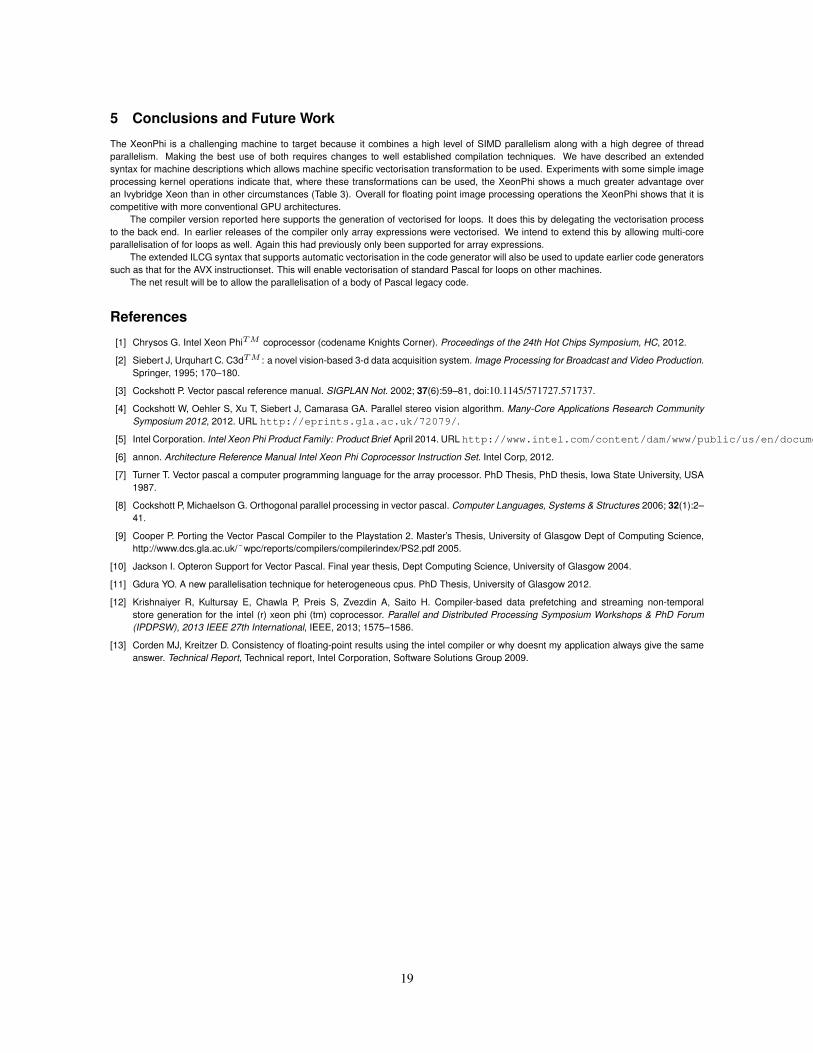
Fig. 8: Log/log plot of convolution times on XeonPhi and 6 core Xeon host, image size.
18
5 Conclusions and Future Work
The XeonPhi is a challenging machine to target because it combines a high level of SIMD parallelism along with a high degree of threadparallelism. Making the best use of both requires changes to well established compilation techniques. We have described an extendedsyntax for machine descriptions which allows machine specific vectorisation transformation to be used. Experiments with some simple imageprocessing kernel operations indicate that, where these transformations can be used, the XeonPhi shows a much greater advantage overan Ivybridge Xeon than in other circumstances (Table 3). Overall for floating point image processing operations the XeonPhi shows that it iscompetitive with more conventional GPU architectures.
The compiler version reported here supports the generation of vectorised for loops. It does this by delegating the vectorisation processto the back end. In earlier releases of the compiler only array expressions were vectorised. We intend to extend this by allowing multi-coreparallelisation of for loops as well. Again this had previously only been supported for array expressions.
The extended ILCG syntax that supports automatic vectorisation in the code generator will also be used to update earlier code generatorssuch as that for the AVX instructionset. This will enable vectorisation of standard Pascal for loops on other machines.
The net result will be to allow the parallelisation of a body of Pascal legacy code.
References
[1] Chrysos G. Intel Xeon PhiTM coprocessor (codename Knights Corner). Proceedings of the 24th Hot Chips Symposium, HC, 2012.
[2] Siebert J, Urquhart C. C3dTM : a novel vision-based 3-d data acquisition system. Image Processing for Broadcast and Video Production.Springer, 1995; 170–180.
[3] Cockshott P. Vector pascal reference manual. SIGPLAN Not. 2002; 37(6):59–81, doi:10.1145/571727.571737.
[4] Cockshott W, Oehler S, Xu T, Siebert J, Camarasa GA. Parallel stereo vision algorithm. Many-Core Applications Research CommunitySymposium 2012, 2012. URL http://eprints.gla.ac.uk/72079/.
[5] Intel Corporation. Intel Xeon Phi Product Family: Product Brief April 2014. URL http://www.intel.com/content/dam/www/public/us/en/documents/product-briefs/high-performance-xeon-phi-coprocessor-brief.pdf.
[6] annon. Architecture Reference Manual Intel Xeon Phi Coprocessor Instruction Set. Intel Corp, 2012.
[7] Turner T. Vector pascal a computer programming language for the array processor. PhD Thesis, PhD thesis, Iowa State University, USA1987.
[8] Cockshott P, Michaelson G. Orthogonal parallel processing in vector pascal. Computer Languages, Systems & Structures 2006; 32(1):2–41.
[9] Cooper P. Porting the Vector Pascal Compiler to the Playstation 2. Master’s Thesis, University of Glasgow Dept of Computing Science,http://www.dcs.gla.ac.uk/˜wpc/reports/compilers/compilerindex/PS2.pdf 2005.
[10] Jackson I. Opteron Support for Vector Pascal. Final year thesis, Dept Computing Science, University of Glasgow 2004.
[11] Gdura YO. A new parallelisation technique for heterogeneous cpus. PhD Thesis, University of Glasgow 2012.
[12] Krishnaiyer R, Kultursay E, Chawla P, Preis S, Zvezdin A, Saito H. Compiler-based data prefetching and streaming non-temporalstore generation for the intel (r) xeon phi (tm) coprocessor. Parallel and Distributed Processing Symposium Workshops & PhD Forum(IPDPSW), 2013 IEEE 27th International, IEEE, 2013; 1575–1586.
[13] Corden MJ, Kreitzer D. Consistency of floating-point results using the intel compiler or why doesnt my application always give the sameanswer. Technical Report, Technical report, Intel Corporation, Software Solutions Group 2009.
19