authority's construction requirements (acrs)
TRANSCRIPT
21CS MIM: Authority’s Construction Requirements Version, Part 1 1
Authority's Construction
Requirements (ACRs):
Section 3 of
Schedule 6 of the
Standard Form Education MIM Project
Agreement
(WEP Strategic Partnering
Framework Version)
Part 1
Generic Design Requirements
July 2019
21CS MIM: Authority’s Construction Requirements Version, Part 1 2
Background Note
This background note is provided in this Standard Form Version but should be deleted prior to incorporation into the Project Agreement.
The Authority’s Construction Requirements comprise Part 1 (including Annex 1 and Annex 2) and Part 2 of Section 3 of Schedule 6 (Construction Matters) of the Template MIM Education Project Agreement. It incorporates the Generic Design Requirements at Part 1 including Statutory Requirements and Guidance Annex 1 and the Site Specific Brief for the relevant Facilities at Part 2. The Site Specific Brief(s) sets out the site-specific requirements including the overarching requirements, Schedule of Accommodation, Loaded Room Layout Drawings, ICT Solution Summary and any agreed derogations to the Generic Design Requirements.
Reference should be made to the "Important Note" at the start of the Template MIM Education Project Agreement for general background to the drafting approach taken throughout the Template MIM Education Project Agreement including the ACRs. Where the project is for maintained community school(s) it is anticipated that some of the references to the "Authority" in Part 1 of the ACRs (which it is envisaged will be the relevant local authority in this context) should be read in some instances as meaning the relevant "School Entity/(ies)", or "the Authority and the School Entity/(ies)", or "the Authority or the School Entity/(ies)". A matrix should be included within the derogations to be set out in [Annex 6] of the Site Specific Brief(s) providing any such additional or alternative references where appropriate..
Part 2 of the ACRs (the Site Specific Brief(s)) will include further requirements applicable to each specific Facility that Project Co will be required to comply with and is to be drafted on a project specific basis. These could be specifically related to the curriculum that will be delivered at the Facility, such as specific subjects delivered at a further education college. They could also be specific to the Site(s) such as any Ground Physical and Geophysical Investigations (where relevant in the context of Clause 10.3 (Responsibility for Ground Conditions and Contamination).
The Site Specific Brief(s)and each of the annexes will be developed in accordance with Schedule 5 of the WEP Strategic Partnering Agreement.
Loaded Room Layout Drawings shall be prepared by Project Co as part of their Stage 2 submission which shall become part of the relevant Site Specific Brief. The Loaded Room Layout Drawings shall be prepared at a scale of 1:50 or as otherwise agreed with the Authority. The Loaded Room Layout Drawings shall show the proposed Equipment layouts for each space and Services Infrastructure including specifically the location of data and power sockets. The Loaded Room Layout Drawings will provide a plan view, elevations of each of the walls and where appropriate a ceiling view of each space. The Loaded Room Layout Drawings shall also include a schedule on the drawing detailing the Equipment (including ICT Equipment) to be placed in the room and also define what Group specification for the Equipment in accordance with Table 41 in section 3 of Part 1 of these ACRs. The Loaded Room Layout Drawings shall also confirm where blinds are to be provided to rooms and their specification.
The Equipment schedule included on the Loaded Room Layout Drawings shall also be included on the respective Area Data Sheet (in Part 6 of Schedule 6 (Construction Matters)).
The requirements for ICT design are set out in Section 4 of Part 1 of these ACRs. The positioning of Equipment will be developed by the Authority and its ICT Installer and will also have a significant impact on shaping the building’s design and services provision. Project Co shall engage with the Authority to

21CS MIM: Authority’s Construction Requirements Version, Part 1 3
ensure that the requirements of the ICT design and use of ICT is also captured on the Loaded Room Layout Drawings.
Project Co shall also be required to ensure that the requirements detailed within the Service Level Specification (contained in Section 1 of Schedule 12 (Service Requirements)) are also captured within their design.
Project Co shall agree a Loose Equipment Purchase Protocol with the Authority. The protocol shall set out how the procurement of Loose Equipment will be co-ordinated between the Authority (and the relevant School Entity in the case of a School(s) project)and Project Co, what Loose Equipment will be procured by the Authority and what by Project Co and all associated arrangements and programme.
21CS MIM: Authority’s Construction Requirements Version, Part 1 4
Table of Contents
Part 1: Generic Design Requirements ..................................................................................... 8
1.1 Definitions ......................................................................................................................... 9
1.2 Key Principles .................................................................................................................... 17
1.3 Compliance ....................................................................................................................... 17
1.4 Key Outcomes ................................................................................................................... 18
1.5 Educational Drivers........................................................................................................... 23
1.6 Curriculum and Organisation ........................................................................................... 23
1.7 Teaching and Pedagogy .................................................................................................... 24
1.8 Behaviour and Pastoral Care ............................................................................................ 24
1.9 SEN (D) .............................................................................................................................. 24
1.10 Health and Well-Being ...................................................................................................... 25
2. Buildings and Grounds ...................................................................................... 26
2.1 Overarching Requirement ................................................................................................ 26
2.2 Site Plan - Overarching Requirement ............................................................................... 26
2.3 Site Layout ........................................................................................................................ 26
2.4 Organisation and Layout - Overarching Requirement ..................................................... 28
2.5 Internal Space - Overarching Requirement ...................................................................... 30
2.6 External Space and Grounds - Overarching Requirement ................................................ 49
2.7 Form and Structure - Overarching Requirement ............................................................. 60
2.8 Building Fabric and Materials - Overarching Requirements ............................................ 61
2.9 Indoor Environmental Requirements ............................................................................. 100
2.10 Energy and utilities ......................................................................................................... 156
2.11 Building Services ............................................................................................................. 175
2.12 Safety and Security ......................................................................................................... 225
2.13 Operability, Maintenance and Construction .................................................................. 232
3. Equipment ............................................................................................................ 241
3.1 Status of this paragraph ................................................................................................. 241
3.2 Allocation of Responsibilities ......................................................................................... 242
3.3 Equipment Provision ..................................................................................................... 245
3.4 Equipment Performance and Quality ........................................................................... 253
3.5 Equipment Life and Procurement ................................................................................. 255
4. ICT Design Requirements ................................................................................ 257
21CS MIM: Authority’s Construction Requirements Version, Part 1 5
4.1 Project Co shall deliver the requirements set out in these ACRs relating to the provision of ICT Infrastructure such that the ICT Infrastructure is capable of delivering the Authority’s ICT solution. 257
4.2 Project Co shall ensure that the ICT Solution Summary aligns with the operational requirements of the school/college. ............................................................................................... 257
4.3 Server Room and Hub Rooms......................................................................................... 259
4.4 ICT Network infrastructure - Passive .............................................................................. 262
4.5 ICT Network infrastructure - Active ................................................................................ 263
4.6 ICT Infrastructure Tests .................................................................................................. 266
4.7 Local Technology – Core ................................................................................................. 267
4.8 Local Technology – AV .................................................................................................... 267
4.9 Automated Systems ....................................................................................................... 268
4.10 Telephony, Internet and TV signal.................................................................................. 269
4.11 ICT Decant Protocol ........................................................................................................ 270
4.12 Local configuration support package ............................................................................. 272
4.13 ICT Responsibilities Matrix ............................................................................................. 272
5. Annex 1 Statutory Requirements and Guidance........................................... 277
5.1 Introduction .................................................................................................................... 277
5.2 Statutory Requirements ................................................................................................. 277
5.3 Regulatory Guidance ...................................................................................................... 278
5.4 Design Guidance ............................................................................................................. 278
5.5 Welsh Government Policy and Guidance ....................................................................... 278
6. Annex 2 ICT Infrastructure Tests .................................................................... 280
21CS MIM: Authority’s Construction Requirements Version, Part 1 6
SECTION 3
AUTHORITY'S CONSTRUCTION REQUIREMENTS
21CS MIM: Authority’s Construction Requirements Version, Part 1 7
Part 1
Generic Design Requirements
21CS MIM: Authority’s Construction Requirements Version, Part 1 8
Part 1: Generic Design Requirements
Interpretation
The requirements in Part 1 of these ACR’s (Generic Design Requirements) apply equally to Primary
School, Secondary School and College Facilities unless specifically excluded from a requirement.
There are also a number of requirements that are referenced as specifically only applying to each
category of Facility, such as covered external play requirements to reception classrooms in Primary
Schools.
Where an All-through School (comprising both Primary and Secondary Students) is proposed the
requirements for both Primary Schools and Secondary Schools will apply.
Should there be discrepancies between the requirements of Part 1 (Generic Design Requirements) and
Part 2 (Site Specific Brief) of these ACRs, Part 2 will take precedence. Within Part 2, the following order
of precedence shall apply:
• Site Specific Brief
• Schedule of Accommodation
• Loaded Room Layout Drawings
• Area Data Sheets
Should there be discrepancies between the Area Data Sheets and the Loaded Room Layout Drawings
in respect of:
• the details of Equipment; and/or
• the data and power socket numbers listed;
then the Loaded Room Layout Drawings will take precedence.
Where any provision of these ACRs requires a particular standard, specification or other requirements
to be observed or achieved in connection with the design and/ or construction of a Facility, the Works
or in relation to a Site (or any part thereof) it shall be Project Co's responsibility to ensure that such
standard, specification or other requirement is met.
21CS MIM: Authority’s Construction Requirements Version, Part 1 9
Overarching Requirements
1.1 Definitions
In this Part 1 (Generic Design Requirements) of Section 3 (Authorities Construction
Requirements) of Schedule 6 (Construction Matters) and elsewhere in this Agreement (save
where Schedule 1 (Definitions and Interpretation) provides to the contrary) the following words
shall have the following meaning:
All-Through School
Generally, a mainstream School for Students aged 4 to 16 or 4 to 18 covering 4 or 5 educational
stages: Foundation Phase (3 to 7 years) and Key Stage 2 (7 to 11 years), Key Stage 3 (11 to 14
years), Key Stage 4 (14 to 16 years) and in some cases the sixth form). For the purposes of these
Generic Design Requirements , all the requirements that apply to Primary and Secondary Schools
would equally apply to an All-Through School;
Access Statement
A description of how inclusive design principles have been incorporated into a development, to be produced in conjunction with a planning application;
Active ICT Infrastructure
Means infrastructure items defined as Active within the ICT Responsibilities Matrix (Table 45) set out in paragraph 4 (ICT Design Requirements) of these ACRs;
Administration offices
Permanently occupied offices, including general office, head teacher’s/ principal’s office, PA to head/ principal;
Approved Document (AD)
Guidance Documents which support the technical parts of the Building Regulations which apply in Wales and have been approved by Welsh Ministers, referred to as 'Approved Documents', as amended from time to time.
AFFL
Means above finished floor level;
Additional Learning Needs (or ALN)
Means additional learning needs or SEN(D);
Area Data Sheets (or ADS)
Means the excel spreadsheets in respect of the relevant Facility set out in Part 2 (Site Specific Brief) of these ACRs. They should identify the requirements for each generic space listed in Annex 2 Schedule of Accommodation of these ACRs and should include dimensions, areas, services and environmental performance and fixed Equipment and ICT Equipment and each external space;
Atria
A College space consisting of fully enclosed, usually, glass covered spaces that are a minimum of double floor height and of sufficient width to offer the opportunity of use as multi-functional space. The total area of College Atria must not exceed 10% of the justified gross internal area;
Authority Requirements and Guidelines
Means the guidance and requirements of the Authroity Set out in Annex 1 to Part 2 of these ACRs (Site Specific Brief);
Automated Energy Data Collection Portal
Means the automated energy data collection portal is that is required for each scheme for ongoing energy monitoring, targeting, and benchmarking, the requirements for which are detailed in the ACRs (at 2.10.1.5).
21CS MIM: Authority’s Construction Requirements Version, Part 1 10
Balance Areas
Areas serving the whole school or college that are not associated with a particular Suite of Spaces, such as a Secondary School dining area or College canteen;
Basic Teaching
The aggregate of all timetabled teaching spaces (except for Halls and PE spaces): including General Teaching spaces, Classrooms, Practical Teaching spaces and Performance Spaces;
BIM
Means Building Information Modelling and is a process for creating and managing information on a
construction project across the project lifecycle. One of the key outputs of this process is the Building
Information Model, the digital description of every aspect of the built asset. This model draws on
information assembled collaboratively and updated at key stages of a project;
Building
Means any building at any time at the relevant Site;
Building Elements
Different parts of any building, including roof and floor structure and coverings, stairs, ceilings, walls, finishes and doors;
Building Management System (BMS)
A control system to manage the automatic operation of building systems and plant services with the required functions detailed in [2.11.39]
Building Regulations
Means the regulations applicable to Wales (or England and Wales) made pursuant to the Building Act 1984.
Building Services
Gas and water services, heating, ventilation, air conditioning, controls, access, security and alarm systems and electrical plant and installations including pipework, ductwork and cabling;
Building User Guide
is a simple to use non-technical guide for the Facilties Premises Team about how their Building
operates and how the local room controls work;
Calming Room
A small room provided in some special units for Students to calm down, designed to safeguard against self-harm;
CIBSE
Means the Chartered Institution of Building Services Engineers;
Circulation
Corridors, stairways and lobbies;
Classroom
A space designed to accommodate a form or class of Students for the purposes of General Teaching, which may also be their registration or teaching base;
College
A further education Facility;
Curriculum
Means the relevant curriculum in Wales and any replacement or revision that is know about prior to entering into this Agreement, including where relevant, the new Curriculum for Wales coming into effect from September 2022 and any updates or subsequent curriculum referred to in the SSB;
21CS MIM: Authority’s Construction Requirements Version, Part 1 11
Department
A Department or faculty within a Secondary School or College based on a subject (e.g. English) or a group of subjects (e.g. humanities);
Designated Unit
Additional specialist facilities on a School Site for a small number of Students, typically less than 30, who usually have an Education and Health Care (EHC) Plan or a statement of special educational need. Students would usually spend the majority of their time there, only attending mainstream classes for a few lessons, such as PE, for assembly or for lunch;
Design and Technology (D&T)
A blanket term for a number of practically based subjects requiring specialist equipment and associated space for safe operation e.g. resistant materials, textiles and graphics;
Dining and Social
Dining spaces which include Secondary School and College dining/canteen and café areas and social areas;
Education and Health Care (EHC) Plan
A plan that identifies the educational, health and social needs of children and young people, and sets out the additional support needed. EHC Plans are gradually replacing statements of special educational need;
Energy Management System (EMS)
A control system to allow energy use at the Facility to be managed with the required functions detailed in [2.11.40]
Existing Buildings
The Buildings at the Facility prior to the relevant Actual Completion Date but excluding any new facilities comprising the Works;
Facility Premises Team
Means the team of Facility Liaison Persons;
Facility User(s)
Means any person who works in, attends or uses the relevant Facility;
FEI
Means further education institutions;
Final Baseline Energy Model
Means the energy model forecasting energy consumption at the Facility based on the actual design and systems proposed, the final model having been updated prior to [Financial Close] to include all the design information for the School/ College including actual profiles, predicted equipment performance and management factors for the actual School/ College Building and Site;
Foundation Phase
Refers to children aged 3 to 7 years. In Schools this is typically children in Nursery, Reception, Year 1 and Year 2;
General Teaching
School and College teaching that typically doesn’t involve practical activities or specialist equipment, for example primary classrooms or classbases, shared teaching areas and large Group rooms, Secondary School and College general Classrooms, seminar rooms, ICT-rich Classrooms and music rooms, drama studios;
Generic Design Requirements
21CS MIM: Authority’s Construction Requirements Version, Part 1 12
Means these Generic Design Requirements which comprise Part 1 of Section 3 (Authorities Construction Requirements) of Schedule 6 ( Construction Matters) of this Agreement, including Annexes [1 to 2].
Gross Area
The overall area of the Buildings, taken to the inside face of the external walls and measured over internal walls, as Gross Internal Area by the Royal Institution of Chartered Surveyors (RICS). As defined for Schools in BB98 and BB99 and defined for Colleges in Welsh Government Addendum to the Estate Strategy Guidance 2007 and the LSC Guidance on the Management of Floor Space 2007 for FEIs in Wales, the minimum Gross Area required includes Plant Area for boiler rooms and a server room, as well as hub rooms and vertical ducts, but further area will be needed if ventilation plant, chimneys or sprinkler tanks are included in the final Gross Area of the designed Building. This excludes the area of voids in Atria and lightwells;
Group rooms and study areas
Teaching rooms generally provided for small group work or private study including Primary School Small Group Rooms, Secondary School and College music group/practice rooms, local resource areas, sixth form and general study areas;
Halls Large teaching spaces including Primary School halls and studios, Secondary School main halls, College lecture theatres and Secondary School and College activity, fitness studios and sport halls;
Grounds
Means all areas of the Site excluding the footprint of the buildings;
Handover and Mobilisation Plan
A plan which sets out the methodolology and detailed programme to achieve ICT Handover and Final
Handover to comply with Schedule 10 (Outline Commissioning Programmes) of this Agreement
Hygiene Room
A specially equipped room for changing and showering Students who have severe physical or Profound and Multiple Learning Disabilities;
ICT Equipment
Means all:
(a) hardware, software, networking equipment, telecommunications equipment, telephone systems, projectors, screens, digital signage, interactive whiteboards, video playback equipment, stage lighting control systems, audio systems, assisted hearing systems, technological sports equipment, cashless catering equipment, registration systems, internal CCTV equipment, peripherals, manuals, documentation and related ICT products and materials; and
(b) the Active ICT Infrastructure;
ICT Infrastructure
Means the Passive ICT Infrastructure and the Active ICT Infrastructure, telephony and internet provision;
ICT Solution Summary
Means the summary of the Facility’s ICT solution as set out in [Annex V] to the relevant Site Specific Brief;
Initial Baseline Energy Model
Means the energy model initialy developed to forecast energy consumption at the Facility based on
the proposed design and systems, the initial model to be submitted at Stage 1 submissions and
updated regularly during Stage 2 to develop into the Final Baseline Energy Model;
Initial ICT Equipment
21CS MIM: Authority’s Construction Requirements Version, Part 1 13
Means the ICT Equipment which are either Legacy ICT Equipment or New ICT Equipment;
Key Stage (KS)
The specific part of a child’s education and relating to their age and year group;
Key Stage 2 (KS2)
Refers to children aged 7 to 11 years. In Schools this is typically children in Year 3, 4 5 and 6;
Kitchen Suite
Spaces comprising Kitchen preparation areas including area of the Facility Kitchen used for preparing food and drink, and washing up afterwards, as well as any workstation for administration and the main servery; and other Kitchen areas including food store rooms; facilities for catering staff, including changing areas and toilets;
Learning Resources
Material that supports learning including printed material and equipment;
Learning Resource Areas
Teaching spaces including Libraries, learning resource centres (LRCs), Group rooms, study areas and practical resource areas including dark rooms, control rooms, kiln rooms and sensory rooms, practical learning resource areas;
Legacy
Items which have been used at the existing site which are considered suitable for use in the Project;
Legacy ICT Equipment
Means existing ICT Equipment which Project Co is required to Decant from an Existing Facility to a
Facility as identified as such in the ICT Solution Summary in Annex 5 of the relevant Site Specific
Brief and on the Area Data Sheets;
Libraries
Teaching spaces that provide Learning Resources including Primary School Libraries and Secondary School and College learning resource centres (LRCs);
Loaded Room Layout Drawings
Means those drawings set out in [Annex 4] to the relevant Site Specific Brief;
Local Exhaust Ventilation (LEV)
Local ventilation of a practical activity, as near to the source of pollutants as possible, such as a fume cupboard or a wood dust extract system, or a heat bay fume extract system;
LTHW
Means low temperature hot water in the context of heating systems
Loose Equipment Purchase Protocol
The protocol which will form part of the Project Co’s Proposals to be agreed between the Authority and the Project Co for the procurement of Loose Equipment set out in [Annex 6] of the relevant Site Specific Brief;
Maintenance Access Strategy
The access strategy and methodology developed by Project Co to ensure that all elements of the
building can be safely accessed to undertake maintenance in accordance with the Law and Good
Industry Practice;
Minimum Life Expectancy
The period of time for which an element, item, or product can be expected to satisfy minimum performance requirements associated with that element, item, or product, when subject to typical
21CS MIM: Authority’s Construction Requirements Version, Part 1 14
conditions, wear, and usage (Malicious Damage is not deemed 'typical' for the purpose of this definition);
Minimum Residual Life Expectancy Requirement
Means the Minimum Life Expectancy for an element, item or product at the Expiry Date as set out in in Column 4 of [Table 1] of these ACRs;
Mobility Equipment
Means a wheelchair, a motorised wheelchair, a walking stick or a standing frame or any other mobility aid required to be used within the Facility;
M&T
Means monitoring and targeting;
Multi-use Games Area (MUGA)
A fenced area with an all-weather surface designed to accommodate a range of sports;
Net Area
The usable area within the Gross Area comprising: Basic Teaching Area; Halls, Dining and Social and PE spaces; Learning Resource Areas; staff and administration; and storage. It includes everything except Non-net Areas;
New Replacement ICT Equipment
Has the meaning given I paragraph [4.11.12] of Part 1 (Generic Design Requirements) of these
ACRs;
Non-net Area
Part of the Gross Area of Buildings not included in the Net Area, comprising: Toilets and personal care, Hygiene Rooms, showers, changing rooms, Kitchen suites, Circulation, plant including boiler, server and hub rooms and plant rooms, and the area taken up by internal walls, comprising all spaces in the Gross Area not included in the Net Area;
Non-net Site Area
Part of the Gross Site Area which supports the functioning of the Site and includes the footprint of buildings and access areas such as paths, roads and parking;
Nursery Classroom
Means a General Teaching space designed to accommodate a form or class of Students below the
age of 5 ;
Nursery and Reception Outdoor Play
An external space directly outside Nursery and Reception Classrooms for outdoor learning and play;
P1 Infrastructure Tests
Means the ICT infrastructure tests set out in [Annex 2] of Part 1 (Generic Design Requirements) of
these ACRs required prior to ICT Handover, as undertaken by the Project Co;
P2 Infrastructure Tests
Means the ICT infrastructure tests set out in [Annex 2] of Part 1 (Generic Design Requirements) of
these ACRs required prior to Payment Commencement Date, as undertaken by the School/College
ICT specialist installer;
Passive ICT Infrastructure
Means infrastructure items defined as Passive within the ICT Responsibilities Matrix set out in paragraph 4 at 4.2.6, 4.4 and table 45] of Part 1 (Generic Design Requirements) of these ACRs;
Performance in Use (PIU) Targets
21CS MIM: Authority’s Construction Requirements Version, Part 1 15
Means the targets set out in the Service Level Specification, Annex 1 to which the Building is required to perform;
Performance Space
An (often) large space designed with acoustic properties to accommodate performance to an audience, also designed to accommodate other activities as well;
Personal Emergency Egress Plans (PEEPs)
A plan developed in consultation with a disabled individual in relation to their escape from a building in an emergency where such person is not capable of making his/her way out of a building without assistance;
Plant Areas
Plant rooms, hub rooms, server rooms, risers and ducts;
Practical Teaching
Teaching that involves Students doing (or watching) practical activities and often requiring access to Service Infrastructure and specialist equipment, for example Primary School specialist practical spaces, Secondary School and College light practical teaching spaces including science labs, art and Design and Technology rooms (such as hair and beauty, graphics, textiles and electronics), heavy practical teaching spaces (such as food rooms and Design and Technology workshops) and College Vocational Teaching spaces;
Preparation areas
Secondary School and College science preparation rooms and preparation rooms for workshops and vocational spaces;
Primary School
Generally, a mainstream School for Students aged 4 to 11 covering 2 educational stages: Foundation Phase (3 to 7 years) and Key Stage 2 (7 to 11 years);
Profound and Multiple Learning Disabilities
People with Profound and Multiple Learning Disabilities have severe and complex learning difficulties as well as other disabilities such as sensory or physical disabilities, complex health needs or mental health difficulties. This range of needs also includes specific learning difficulties which encompasses a range of conditions such as dyslexia, dyscalculia and dyspraxia;
Reception Classroom
Means a General Teaching space designed to accommodate a form or class of Students in their
reception year.
Room User Guide
Means a simple guide or pictogram provided by Project Co for staff (e.g. teachers) on how to use
room systems e.g. lighting, ventilation, heating. This shall be provided for each occupied space;
Schedule of Accommodation (SoA)
Means the Excel spread sheet listing all the spaces in the Facility, the size of each space and (for
teaching spaces) the maximum group size they will accommodate as set out in [Annex 2] of the
relevant Site Specific Brief. Spaces are listed under Net and Non-net Area (ref). The Schedule of
Accommodation also indicates the number of Students and the Facility type. The Schedule of
Accommodation will also list all external spaces, including the area of each external space.
On multi-facility projects, reference to Schedule of Accomodation or SoA means the Excel spread
sheet in respect of the relevant Facility.
School
Means a Primary School or a Secondary School;
Secondary School
21CS MIM: Authority’s Construction Requirements Version, Part 1 16
Generally, a mainstream school for Students aged 11 to 16 or 19 covering 2 or 3 educational stages: Key Stage 3 (11 to 14 years), Key Stage 4 (14 to 16 years) and in some cases the sixth form). For the purposes of these General Design Requirements, a Secondary School includes middle-deemed Secondary Schools that provide for Students aged 8 to 13;
Secure Line
The agreed demarcation between secure and public areas of the Facility Buildings and Grounds for the purposes of safeguarding and security;
Service Infrastructure
Means the infrastructure associated with Building Services, including but not limited to pipework,
cables, wires, sockets and conduits;
SEN (D)
Special educational needs (and/or disability), also referenced as Additional Learning Needs (ALN);
Site Specific Brief (SSB)
Means the site specific brief comprising Part 2 of Section 3 (Authority's Construction Requirements) of Schedule 6 (Construction Matters) (including Annexes [ I to V]) provides key data for a specific Facility and sets out any requirements for that Facility which are additional or alternative to the ACR;
Small Group Room
A teaching space designed to accommodate an individual or a part of a class that is a discrete, quiet spaces for learning support, behaviour management or private counselling. Small Group Rooms designed for individual or small group music activities are sometimes called music practice rooms;
Soft Services
Means Grounds maintenance; caretaking and portering; cleaning, resource and waste management, and pest control; catering; health and safety; fire safety management and security; and management of the Soft Services;
Specially Resourced Provision
Additional specialist facilities in a mainstream School Site for a small number of Students, typically less than 30, who usually have EHC plans or statements of special need. Students spend most of their time in mainstream classes, attending the SRP facilities for individual support, to learn a specific skill, to receive medical or therapeutic support or to access specialist equipment. The facilities can be in a suite or dispersed throughout the school;
Staff Areas
Staff utilised spaces including Interview room, sick bay or sick room, reprographic facilities, staff room, staff work rooms, offices, meeting or conference rooms, offices / workshops for facilities manager or ICT technician;
Storage
Means teaching storage, including chemical and material stores; and non-teaching storage, including cloakrooms and lockers;
Soft Landings Framework
means the BSRIA-led process designed to assist the construction industry and its clients deliver
better buildings;
Suite of Spaces
A group of spaces, which could be teaching or non-teaching, associated by type of activity, such as General Teaching or Practical Teaching, and supported by smaller support spaces such as store rooms and toilets. Spaces can be grouped in different ways to form a suite;
Teaching Resources
Material that supports teaching and learning including printed material and equipment;
21CS MIM: Authority’s Construction Requirements Version, Part 1 17
Toilets and personal care (non-net)
Facilities for staff, Students and visitors including toilets, accessible toilets and Hygiene Rooms and changing rooms and showers;
Useful Daylight Illuminance (UDI)
UDI is the annual occurrence of illuminances, for the hours of operation, across the work plane that are within a range considered “useful” by occupants as further defined in paragraph [2.9.10.1] of the Generic Design Requirements and in CIBSE Lighting Guide 10;
VOC
Means volatile organic compounds;
Vocational Teaching
A blanket term for a number of vocational and work-based subjects requiring light and heavy practical spaces with specialist equipment, predominantly in Colleges, including, but not limited to, hair and beauty, health and beauty, construction, hospitality and catering and automotive mechanics;
UPS
Means an uninterruptable power supply meeting the requirements of paragraph [4.3.17] of the Generic Design Requirements;
1.2 Key Principles
1.2.1 Project Co shall and Project Co's Proposals shall comply with and address all elements of the Authority’s Construction Requirements, including the Generic Design Requirements, the relevant Site Specific Briefs, the SoA and the ADS in Section 3 of this Schedule 6 (Project Co’s Proposals) of this Agreement.
1.2.2 Project Co shall also be required to ensure that the requirements detailed within the Service Level Specification (contained in Section 1 of Schedule 12 (Service Requirements)) are also captured within their design.
1.3 Compliance
1.3.1 Project Co shall ensure that the Buildings, Grounds and Equipment provided for all the Site[s] comply with all relevant and current regulations, Welsh, British and European standards and policies including without limitation those referenced in footnotes and/or listed in the Site-specific Annexes. Many of these, but not all, are referenced in footnotes and/or listed in Annex 1 and in the annexes to the relevant Site Specific Briefs (local and planning for each Facility).
1.3.2 Where specific references are made to the parts of the Building Regulations, they are usually denoted as Part L, Part M etc. Where references are made to Approved Documents, they are noted as AD A, AD B etc.
1.3.3 Equipment manufacturers used by Project Co shall have current BS EN ISO 14001 compliance.
1.3.4 Where the Project is to be undertaken at an Existing Facility, Project Co shall be responsible for ensuring that the whole Facility within the Site[s] shall comply with all requirements in these ACRs. Where there are retained Building Elements, structures, facilities and Grounds, Project Co shall replace or upgrade these to comply with these ACRs.
21CS MIM: Authority’s Construction Requirements Version, Part 1 18
1.3.5 Where the requirements refer to an area, space or Suite of Spaces, these requirements shall apply to all spaces in any Facility. Any area or space within Facilities shall conform to all relevant requirements in these ACRs.
1.3.6 The requirements in these ACRs in respect of external space and Grounds:
shall always apply to the external areas adjacent to any Building(s) which are
required for access or which are affected or removed due to the proposed Works,
including any informal and social area adjacent to Foundation Phase Classrooms
or Primary School Classrooms;
shall apply to existing Grounds within the Site except for any part that is
specifically described in the SSB; and
shall not apply to existing Grounds beyond the Site except for any part that is
specifically described in the SSB (for instance for consequential work).
1.3.7 Where it is agreed that Project Co is not able to meet the requirements of these Generic Design Requirements in full, due to the limitations of the Site[s] or the Buildings on the relevant Site prior to the Works, details of the derogation from the specific provision of these Generic Design Requirements and any replacement requirement will be set out in the Site Specific Brief.. Project Co will not be required to comply with such requirements where the Authority's agreement to such derogation from these Generic Design Requirements is specifically recorded in each Site Specific Brief.
1.4 Key Outcomes
1.4.1 Project Co shall ensure that the design and construction of all Facilities, and any Equipment and ICT Infrastructure provided by Project Co, meets the following six overarching outcomes of functionality; health and safety; standardised approach; future proofing; Minimum Residual Life Expectancy Requirements and sustainable design and construction.
1.4.2 Functionality
1.4.2.1 The Works and the Facilities shall be suitable for their intended purpose and provide an environment appropriate to a School or College, which supports the Education Drivers outlined in [paragraph 2.3] ofeach Site Specific Brief. The design shall also meet the educational and organisational requirements of each Site Specific Brief, taking account of the age ranges of the Students, and of the constraints of each Facility and of any Buildings on the relevant Site prior to the Works.
1.4.3 Health and Safety
1.4.3.1 The layout and design of the Site, the Buildings, including Building Services, ICT Infrastructure, Plant and Equipment, are to provide a safe and secure environment for Students and staff. People with SEN (D), including those using Mobility Equipment and those with a visual or hearing impairment, must not be placed at a disadvantage by the design of the Works or the Facilities.
1.4.3.2 All Works shall be designed and constructed in line with The Construction (Design and Management) Regulations 2015.
1.4.4 Future Proofing
1.4.4.1 The Buildings, Grounds, any Equipment and ICT Infrastructure provided by Project Co shall be designed, constructed or procured so that later changes can be achieved easily and cost-effectively. These would be in response to changes in Curriculum priorities
21CS MIM: Authority’s Construction Requirements Version, Part 1 19
including the new Curriculum for Wales 2022, organisation, technology and, where required in the relevant Site Specific Brief, Student numbers. Essential changes in the sizes of teaching rooms in the future should be achievable without major Building work.
1.4.5 Minimum Life Expectancy and Residual Life
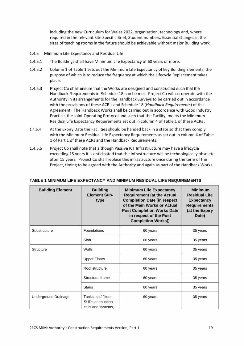
1.4.5.1 The Buildings shall have Minimum Life Expectancy of 60 years or more.
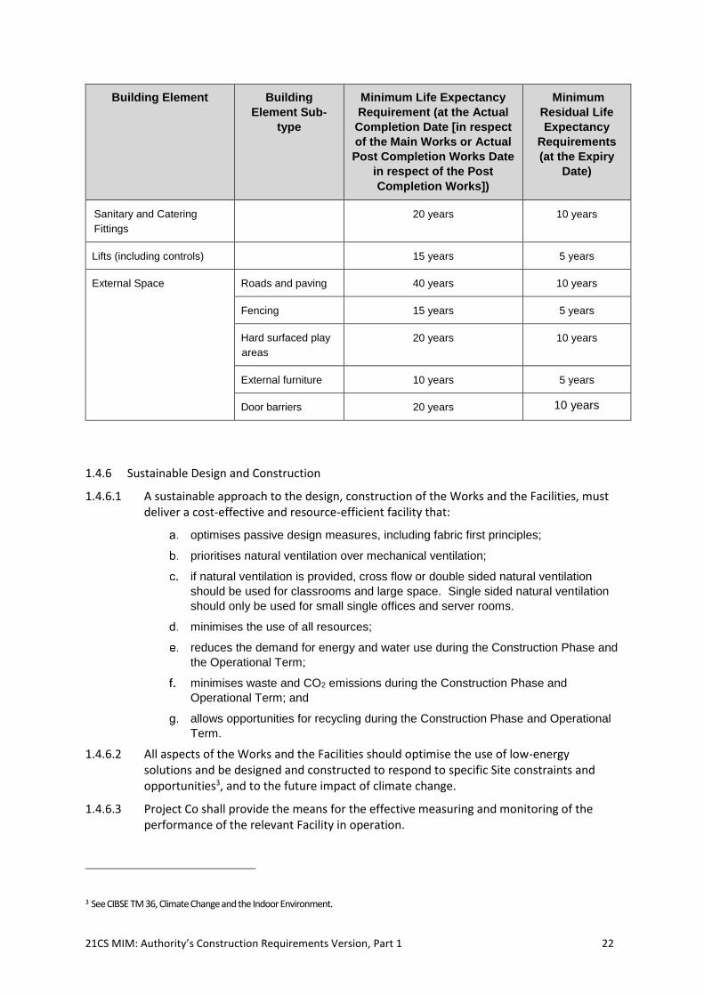
1.4.5.2 Column 1 of Table 1 sets out the Minimum Life Expectancy of key Building Elements, the purpose of which is to reduce the frequency at which the Lifecycle Replacement takes place.
1.4.5.3 Project Co shall ensure that the Works are designed and constructed such that the
Handback Requirements in Schedule 18 can be met. Project Co will co-operate with the Authority in its arrangements for the Handback Surveys to be carried out in accordance with the provisions of these ACR’s and Schedule 18 (Handback Requirements) of this Agreement. The Handback Works shall be carried out in accordance with Good Industry Practice, the Joint Operating Protocol and such that the Facility, meets the Minimum Residual Life Expectancy Requirements set out in column 4 of Table 1 of these ACRs .
1.4.5.4 At the Expiry Date the Facilities should be handed back in a state so that they comply with the Minimum Residual Life Expectancy Requirements as set out in column 4 of Table 1 of Part 1 of these ACRs and the Handback Requirements.
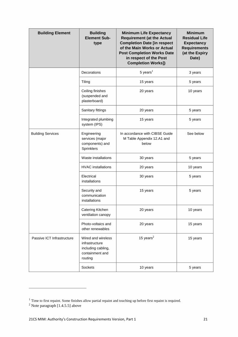
1.4.5.5 Project Co shall note that although Passive ICT Infrastructure may have a lifecycle exceeding 15 years it is anticipated that the infrastructure will be technologically obsolete after 15 years. Project Co shall replace this infrastructure once during the term of the Project, timing to be agreed with the Authority and again as part of the Handback Works.
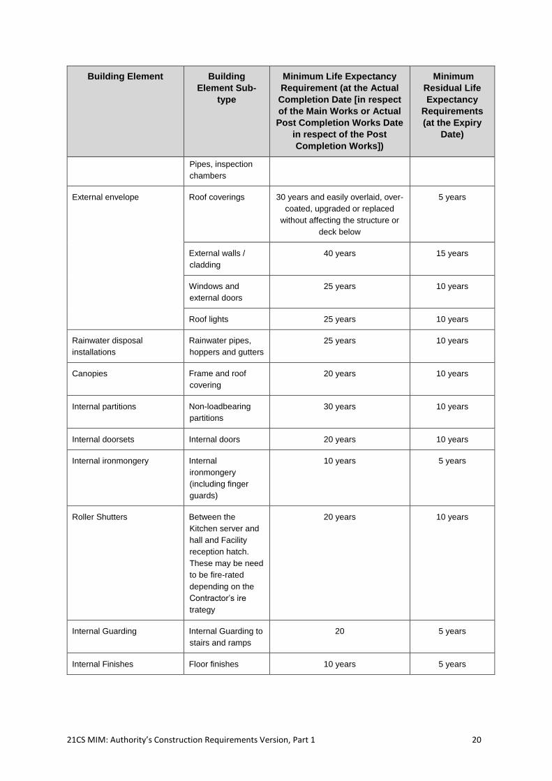
TABLE 1 MINIMUM LIFE EXPECTANCY AND MINIMUM RESIDUAL LIFE REQUIREMENTS
Building Element Building
Element Sub-
type
Minimum Life Expectancy
Requirement (at the Actual
Completion Date [in respect
of the Main Works or Actual
Post Completion Works Date
in respect of the Post
Completion Works])
Minimum
Residual Life
Expectancy
Requirements
(at the Expiry
Date)
Substructure Foundations 60 years 35 years
Slab 60 years 35 years
Structure Walls 60 years 35 years
Upper Floors 60 years 35 years
Roof structure 60 years 35 years
Structural frame 60 years 35 years
Stairs 60 years 35 years
Underground Drainage Tanks, leaf filters,
SUDs attenuation
cells and systems,
60 years 35 years
21CS MIM: Authority’s Construction Requirements Version, Part 1 20
Building Element Building
Element Sub-
type
Minimum Life Expectancy
Requirement (at the Actual
Completion Date [in respect
of the Main Works or Actual
Post Completion Works Date
in respect of the Post
Completion Works])
Minimum
Residual Life
Expectancy
Requirements
(at the Expiry
Date)
Pipes, inspection
chambers
External envelope Roof coverings 30 years and easily overlaid, over-
coated, upgraded or replaced
without affecting the structure or
deck below
5 years
External walls /
cladding
40 years 15 years
Windows and
external doors
25 years 10 years
Roof lights 25 years 10 years
Rainwater disposal
installations
Rainwater pipes,
hoppers and gutters
25 years 10 years
Canopies Frame and roof
covering
20 years 10 years
Internal partitions Non-loadbearing
partitions
30 years 10 years
Internal doorsets Internal doors 20 years 10 years
Internal ironmongery Internal
ironmongery
(including finger
guards)
10 years 5 years
Roller Shutters Between the
Kitchen server and
hall and Facility
reception hatch.
These may be need
to be fire-rated
depending on the
Contractor’s ire
trategy
20 years 10 years
Internal Guarding Internal Guarding to
stairs and ramps
20 5 years
Internal Finishes Floor finishes 10 years 5 years
21CS MIM: Authority’s Construction Requirements Version, Part 1 21
Building Element Building
Element Sub-
type
Minimum Life Expectancy
Requirement (at the Actual
Completion Date [in respect
of the Main Works or Actual
Post Completion Works Date
in respect of the Post
Completion Works])
Minimum
Residual Life
Expectancy
Requirements
(at the Expiry
Date)
Decorations 5 years1 3 years
Tiling 15 years 5 years
Ceiling finishes
(suspended and
plasterboard)
20 years 10 years
Sanitary fittings 20 years 5 years
Integrated plumbing
system (IPS)
15 years 5 years
Building Services Engineering
services (major
components) and
Sprinklers
In accordance with CIBSE Guide
M Table Appendix 12.A1 and
below
See below
Waste installations 30 years 5 years
HVAC installations 20 years 10 years
Electrical
installations
30 years 5 years
Security and
communication
installations
15 years 5 years
Catering Kitchen
ventilation canopy
20 years 10 years
Photo-voltaics and
other renewables
20 years 15 years
Passive ICT Infrastructure Wired and wireless
infrastructure
including cabling,
containment and
routing
15 years2 15 years
Sockets 10 years 5 years
1 Time to first repaint. Some finishes allow partial repaint and touching up before first repaint is required. 2 Note paragraph [1.4.5.5] above
21CS MIM: Authority’s Construction Requirements Version, Part 1 22
Building Element Building
Element Sub-
type
Minimum Life Expectancy
Requirement (at the Actual
Completion Date [in respect
of the Main Works or Actual
Post Completion Works Date
in respect of the Post
Completion Works])
Minimum
Residual Life
Expectancy
Requirements
(at the Expiry
Date)
Sanitary and Catering
Fittings
20 years 10 years
Lifts (including controls) 15 years 5 years
External Space Roads and paving 40 years 10 years
Fencing 15 years 5 years
Hard surfaced play
areas
20 years 10 years
External furniture 10 years 5 years
Door barriers 20 years 10 years
1.4.6 Sustainable Design and Construction
1.4.6.1 A sustainable approach to the design, construction of the Works and the Facilities, must deliver a cost-effective and resource-efficient facility that:
optimises passive design measures, including fabric first principles;
prioritises natural ventilation over mechanical ventilation;
if natural ventilation is provided, cross flow or double sided natural ventilation
should be used for classrooms and large space. Single sided natural ventilation
should only be used for small single offices and server rooms.
minimises the use of all resources;
reduces the demand for energy and water use during the Construction Phase and
the Operational Term;
minimises waste and CO2 emissions during the Construction Phase and
Operational Term; and
allows opportunities for recycling during the Construction Phase and Operational
Term.
1.4.6.2 All aspects of the Works and the Facilities should optimise the use of low-energy solutions and be designed and constructed to respond to specific Site constraints and opportunities3, and to the future impact of climate change.
1.4.6.3 Project Co shall provide the means for the effective measuring and monitoring of the performance of the relevant Facility in operation.
3 See CIBSE TM 36, Climate Change and the Indoor Environment.
21CS MIM: Authority’s Construction Requirements Version, Part 1 23
1.4.6.4 Project Co shall design build and operate the Facilities in accordance with BS EN ISO 14001 including the maintenance of an 'Environmental Management Plan' that records all agreed targets for the key aspects of environmental performance identified in these ACRs and the Service Level Specification. This will include assessment and reporting of the agreed environmental performance criteria for the project. This will include an assessment against BREEAM New Construction Education criteria, being a Welsh Government requirement, to achieve the BREEAM “excellent” target.
1.4.6.5 Project Co shall design the Works and the Facilities so that an efficient approach to Maintenance Works, Lifecycle Replacement, facilities management and the provision of Soft Services, such as cleaning and security, can be provided in a cost-effective way. There should be no inaccessible areas which are either difficult to clean or difficult to supervise.
1.4.6.6 Project Co shall ensure that they achieve a minimum recycled and reused content of at least 15% of the total value of the materials used in the Works.
1.4.6.7 Project Co shall design the Works to maintain and enhance biodiversity and the resilience of ecosystems on the Site in so as to be compliant with the obligations and duties placed on public authorities under s6 of The Environment (Wales) Act 2016. This includes but is not limited to:-
• the resilience of ecosystems
• diversity between and within ecosystems;
• the connections between and within ecosystems;
• the scale of ecosystems;
• the condition of ecosystems (including their structure and functioning); and
• the adaptability of ecosystems.
1.4.6.8 Project Co will provide such support and reasonable assistance as the Authority may reasonably require in connection with its obligation and duties under the Environment (Wales) Act 2016.
1.4.7 BIM
1.4.7.1 Project Co is required to provide Level 2 BIM.
1.4.7.2 Project Co shall comply with the Soft Landings Framework and BS8536
1.4.7.3 Project Co shall also comply with the Project BIM Agreement .
1.4.7.4 Project Co must ensure the BIM model has all relevant and required construction, operation and maintenance information provided at the required stages of design and construction and in accordance with the best practice guidance outlined above.
1.5 Educational Drivers
1.5.1 Project Co shall ensure that the design of the Works and each Facility meets the Educational Drivers of these ACRs detailed in the relevant Site Specific Brief.
1.6 Curriculum and Organisation
1.6.1 Project Co shall design each Facility provide for Suites of Spaces for teaching, each with enough adaptable space to be able to accommodate a range of learning scenarios, both now
21CS MIM: Authority’s Construction Requirements Version, Part 1 24
and in the future. For Schools, Project Co shall take account of the requirements of the new School Curriculum for Wales planned for September 2022 (and any updates or any replacement curriculum referred to in the SSB).
1.6.2 Project Co shall also provide accommodation that supports and encourages learning outside the formal timetable through innovative and thoughtful design of the outdoor space and Dining and Social area.
1.7 Teaching and Pedagogy
1.7.1 Project Co shall design all Facilities and Grounds to create an environment conducive to effective teaching through the provision of:
work-space in each suite that enables teachers to plan and prepare in groups and
individually;
Learning Resource Areas in each suite for small group work and for staff to have
individual discussions with Students so that feedback can be given to them on
their progress;
ICT Infrastructure and building design which allows the best use of ICT
equipment that is available now and in the future;
designs which allow a range of potential Loaded Room Layout Drawings, which is
well co-ordinated with Equipment, ICT Infrastructure and Building Services;
some internal transparency between the central Circulation and teaching spaces,
wherever possible, so that Facility Users are visible to others in that suite;
a design that allows Facility Users to engage and interact with the external
environment, where possible, so as to create practical hands-on learning, with a
direct connection to the outdoors in Foundation in Primary Schools and for some
Specially Resourced Provision or designated settings; and
a design that relates to the community, particularly where SSB’s identify
Vocational Teaching facilities that replicate working environments.
1.8 Behaviour and Pastoral Care
1.8.1 Project Co shall design each Facility to create an environment that supports behaviour and pastoral care and allows for passive supervision through the provision of:
entrance and Circulation areas that allow space for safe and comfortable
movement;
offices and staff workrooms that are located and designed to support passive
supervision;
distinct Suites of Spaces that break down the scale of large Facilities; and
toilets that are positioned for easy access and to facilitate passive supervision.
1.9 SEN (D)
1.9.1 Project Co shall design any Facilities and Grounds provided such that a Student with SEN (D) or ALN is not placed at a disadvantage in terms of access to teaching, learning and social spaces. Project Co shall provide the SEN(D) facilities listed in the Schedule of Accommodation, including in Schools any associated Specially Resourced Provision or Designated Units, and to meet the particular requirements of the SSB.
21CS MIM: Authority’s Construction Requirements Version, Part 1 25
1.9.2 Project Co shall ensure that the environmental design and the building fabric are appropriate to the needs of Students and others with SEN (D) or ALN, including any SEN (D) or ALN specific needs described in the these ACRs.
1.9.3 Project Co shall make every space in a suite accessible, for an accessible toilet to be available from each Suite of Spaces.
1.10 Health and Well-Being
1.10.1 Project Co shall provide an effective healthy indoor environment with daylight and electric lighting, ventilation, thermal comfort and acoustics which are designed to support educational attainment. Project Co shall ensure that themes in The Wellbeing of Future Generations (Wales) Act, 2015 and the proposed changes to Curriculum for Wales which introduces health and well-being as one of the six areas of learning are reflected in their design statement.
1.10.2 Project Co shall provide a healthy, safe environment with an area that can accommodate a civilised dining experience, linked to a catering area within which healthy meals can be prepared and delivered.
1.10.3 Project Co shall ensure that sport facilities may be open to the community outside theCore Sessions without adversely affecting the Facility's security.
21CS MIM: Authority’s Construction Requirements Version, Part 1 26
2. Buildings and Grounds
2.1 Overarching Requirement
2.1.1 This paragraph gives the generic requirements for Facilities and Grounds which apply to each Facility. In producing the Project Co’s Proposals, Project Co shall consider and address all elements of these ACRs. Although Project Co may suggest alternative approaches, these ACRs shall only be changed or relaxed where specific derogations are agreed by the Authority and included in Annex 7 (Derogations)of the relevant Site Specific Brief.
2.2 Site Plan - Overarching Requirement
2.2.1 Project Co shall ensure that the design maximises the potential use of the Sites, locating and orientating any Buildings in a manner that will create suitable internal and external spaces and allow possible future extensions. All Facility Users must be able to find their way safely and easily around Buildings and Grounds. Project Co shall ensure that the design makes good use of the Site, balancing the needs of pedestrians, cyclists and vehicles and dealing with any Site-specific constraints. All Facility Users must be able to find their way safely and easily around Buildings and Grounds in accordance with AD M and BS 8300-1:2018, and BS 8300-2:2018.
2.3 Site Layout
2.3.1 Project Co shall ensure that the layout of any Building(s) and Grounds on the relevant Site:
takes account of the character of the area and topography of the relevant Site,
including its shape, contours and subsoil; and the local vegetation, ecology and
micro-climate;
takes account of existing utilities service routes;
orientates the Facility Buildings on the site to optimise passive environmental
design principles;
takes account of biodiversity on the site with particular attention to resident
species and plants, including undertaking surveys for the presence of bats and
endangered species and acting upon the findings;
mitigates the effects of adverse environmental conditions, such as traffic noise,
including any highlighted in the relevant Site Specific Brief;
locates quieter activities away from noisier activities and neighbourhood noise,
wherever possible;
takes into account the needs of neighbours in close proximity;
ensures the safety and security of Students, staff and visitors;
provides clearly defined boundaries which discourage trespass and vandalism
and provide good visibility to facilitate surveillance across the site;
provides car parking, in line with the planning requirements;
(for Secondary Schools in particular) provides easy movement between changing
rooms and outdoor PE facilities, and between parking areas and parts of the
Buildings and Grounds likely to be used outside the Core Day; and
21CS MIM: Authority’s Construction Requirements Version, Part 1 27
protects existing Site features worthy of retention where desirable and
practicable, including existing trees in accordance with BS 5837:2012 ‘Trees in
relation to design, demolition and construction – Recommendations’.
2.3.2 Site Access
2.3.2.1 Project Co shall ensure that thedesign of all Sites takes account of access needs of the emergency services and seeks to resolve potential conflicts between different movements, ensuring the safety and security of Students, staff and visitors. The landscape and layout shall be designed to give priority to pedestrians while allowing appropriate access for vehicles.
2.3.2.2 Project Co shall ensure that the design of each Site provides for:
safe and convenient access for pedestrians, cyclists and vehicles, including
emergency vehicles, balancing the demands of different users and keeping
vehicular movement within the Grounds to a minimum, and as far as possible
separate from pedestrian routes;
fire and emergency escape routes leading to safe places of assembly (on existing
sites, the construction project should maintain or improve the accessibility of
emergency vehicles on and around the Sites);
access to and through soft landscape areas along defined pathways that do not
require special footwear and are easily maintained, with any all-weather surfaces
provided being located so that Facility Users do not have to cross grass to reach
them;
access for service vehicles and secure storage for goods and waste awaiting
collection;
separate and safe access for deliveries, maintenance vehicles and waste removal
and collections from site, appertaining to the execution of the Works and/or
Services; and
suitable access around the Building for maintenance of the Grounds and building
façade.
2.3.2.3 Project Co shall produce and comply with a monitored process of entry and exit agreed with the Authority, either through security or physical barriers to entry or exit with acknowledgement and authorisation processes.
2.3.2.4 Project Co shall demonstrate the availability of safe drop-off and pick-up points, for school buses and private vehicles and comply with the Active Travel Design Guidance. These can be off-site, if appropriate walking routes exist. The Active Travel (Wales) Act 2013 seeks to increase the numbers of everyday journeys made on foot and by bike, such as the journey to school. As a result of the Act, local authorities need to plan and develop integrated active travel networks, connecting key trip generators, including Schools and Colleges. The Works shall be designed and constructed so as to ensure that each Site includes provision of safe and convenient walking and cycling access.
2.3.2.5 Project Co shall manage deliveries and collections to and from each Site so as not to interfere with the delivery of education at the Facility or the movement of Facility Users about the Site.
21CS MIM: Authority’s Construction Requirements Version, Part 1 28
2.3.2.6 Students with SEN (D) are likely to be less aware of traffic risks and may not see hear vehicles, and Project Co shall make relevant adjustments when designing access routes to accommodate their particular needs.
2.3.2.7 Project Co shall ensure that main and secondary Site entrances are located to take account of pedestrian and vehicular routes adjacent to the Site (including public transport). The entrances shall incorporate controlled access and allow clear visual supervision in order for the Facility to manage the movement of Students and visitors onto and off the Site.
2.3.2.8 Project Co shall ensure that there shall be no more than two easily controlled access points to each School/ College site where possible (and other access points as specified in the the relevant Site Specific Brief), located so that they allow clear visual supervision in order for the Facility to manage the movement of Students and visitors onto and off the Site.
2.3.2.9 Ensure that access complies with these ACRs. Consideration to be given to the location context as Colleges are more likely to have areas open to the public; access and security will be detailed in the SSB.
2.3.2.10 Where required, Project Co shall provide updates to security systems, for example number plate recognition at a reasonable cost.
2.3.2.11 Project Co shall design the Site for accessibility and this shall be reflected in the Access Statement that Project Co provides. All main access routes including roads, paths, ramps and entrances shall be fully negotiable, including by people with limited mobility in accordance with Part M and BS 8300-1:2018, and BS 8300-2:2018.
2.3.2.12 Ensure that all Buildings and Grounds are designed to include suitable guarding and barriers where there is a risk of falling, including pedestrian and vehicle barriers, and suitable requirements to prevent injury from (opening) doors and windows in accordance with AD K.
2.3.2.13 Project Co shall provide a clear hierarchy of Circulation routes with easily-supervised and clearly identified entry points to all Buildings and signage directing visitors from the entry of each Site to the visitor’s reception. Project Co shall ensure that entry/exit points for Students are controllable either within the Building or within the overall Site.
2.3.2.14 Ensure that when a Building is some way back from the public highway, road access for fire appliances (and other large vehicles i.e. waste collection) is provided, and that any entrances through which appliances may need to pass satisfy AD B requirements, and that there is adequate space to enable appliances to turn.
2.3.2.15 Where a Nursery and Reception Classroom is provided, Project Co shall ensure that parents and/or carers can gain access to the nursery to collect & drop-off children throughout the day without entering the main School and without crossing any external play space, including the nursery play area. There shall be sufficient space close to this entrance for 15 parents with buggies to gather before gaining access or as otherwise required in the relevant Site Specific Brief.
2.4 Organisation and Layout - Overarching Requirement
2.4.1 Project Co shall ensure that the Buildings provide all the teaching, support and other spaces specified in the SoA, to suit the Curriculum and organisation for the number of Student places planned. Project Co shall ensure that all such spaces are the right size, proportions and specification for their functions, as defined in the ADS.
21CS MIM: Authority’s Construction Requirements Version, Part 1 29
2.4.2 Project Co shall ensure that the design and construction of any internal spaces complies with the guidance in Building Bulletin 98 – ‘Building Framework for Secondary School projects’ (BB98), Building Bulletin 99 - Building Framework for Primary School projects (BB99), and Building Bulletin 104: ‘Area guidelines for SEN (D) and alternative provision’ (BB104) and for College projects the LSC Guidance on the Management of Floor Space 2007 for FEIs in Wales.
2.4.3 Project Co shall ensure that the layout of the Facilities allows the Facilities to be used outside of Core Sessions. As a minimum, security systems, fire alarm systems, heating and cooling shall be zoned so that the following are provided with separate zones:
sports facilities, including change areas and toilets;
main hall, including any catering facilities, and toilets;
community use adult education teaching facilities, including toilets; and
any other spaces as identified in these ACRs e.g. Nursery classroomscommunity
rooms, areas used for before and after school clubs, and areas of College
Facilities to be open at evening and weekends such as a restaurant.
2.4.4 Typical Organisation
2.4.4.1 Project Co shall ensure that all spaces are located so that there is a clear spatial diagram for the Building that is appropriate for the Curriculum and organisation of each Facility, in line with any adjacency diagrams in the relevant Site Specific Brief. Spaces shall be linked by well organised Circulation space that suits the likely movement and numbers of Students.
2.4.4.2 Project Co shall ensure that the Building’s layout provides the right balance and distribution of space, in line with the SoA and the adjacency diagrams in the relevant Site Specific Brief. Each Facility will comprise appropriate Suites of Spaces depending on the type of and/or requirements of the Facility. The SoA for each Facility will be organised in a number of Suites of Spaces, avoiding small independent groups of rooms wherever possible. Any exceptions to this generic requirement will be identified in each of the Site Specific Briefs.
2.4.4.3 Project Co shall ensure that all internal spaces are numbered with recognisable labels and shown on the Buildings and Grounds layout plans. They shall also include the identification of spaces identified for the delivery of the Services along with a statement of their function (e.g., office, cleaning stores etc). The door signs shall be updatable, e.g. for change of staff names.
2.4.4.4 Project Co shall ensure that the design and layout of Buildings and Grounds will include the space requirements to deliver the Soft Services including storage and office space as defined in the ADSs. They will be organised to enable delivery of the required services, to the service levels required to positively support the Facility's Curriculum delivery.
2.4.4.5 Project Co shall design these Suites of Spaces to accommodate the model of education that each Facility is proposing in the relevant Site Specific Brief, taking into account the possibility of future changes. In particular:
each Suite of Spaces shall provide the right number of spaces;
each suite of teaching spaces, other than a hall and Performance Spaces, shall
be adjacent to other similar spaces wherever possible;
each suite of teaching spaces shall be able to be linked to, or expanded into, an
adjacent suite of teaching spaces in the future; and
21CS MIM: Authority’s Construction Requirements Version, Part 1 30
the configuration of spaces must be able to expand, contract and reform in as
many ways as is economically feasible.
2.4.4.6 Project Co shall provide teaching spaces that are visible from the Circulation area in that Suite of Spaces, for instance by providing vision panels in doors. Any exceptions to this shall be specified in the SSB. Project Co shall ensure that all spaces may be accessed from an adjacent Circulation area except store rooms and (where appropriate) toilet and hygiene facilities that are accessed directly from learning spaces or as stated otherwise in these ACRs.
2.4.4.7 Project Co shall not design long lengths of dark or narrow corridor with teaching spaces on both sides. Where long corridors are needed, Project Co shall relieve the impact by introducing light and views through teaching spaces, glazed offices and staircases.
2.4.4.8 In designing the Facilities, Project Co shall comply with Part M; ‘Access to and Use of Buildings’. Project Co shall ensure that all new Buildings are fully accessible to all people including those with impaired movement or other disabilities. Where Buildings are to be refurbished Project Co shall ensure that all Students have full access to the Curriculum. There shall be clarity in the arrangement and location of entrances, main Circulation routes and key spaces. The Building layout shall be clearly organised to enable ease of circulation for Students, visitors and staff, and to aid orientation and ease of movement to external areas – particularly in event of emergency. This shall be achieved through the layout of the Building and not just rely on signage.
2.5 Internal Space - Overarching Requirement
2.5.1 Project Co shall ensure that each Facility has sufficient teaching and support spaces to suit the Curriculum and organisation for the number of Student places planned, as specified in the SoA. Project Co shall ensure that:
all such spaces are the right size, proportions and design for their functions, as
defined in the ADS;
that areas for catering, Dining and Social space are sufficient to allow for healthy
and civilised eating and recreation; and
the design of the Building layout, zoning of the Building Services and security
shall contemplate that the Facility will be used outside of the Core Sessions, for
example by the community.
2.5.2 Dimensions and Proportions
2.5.2.1 The Net Area of any space shall be at least that required in the SoA excluding:
the area of any through Circulation to adjacent spaces;
any area outside of the orthogonal shape that provides only Circulation (i.e. a
lobby without a second door); and
the Net Area of any support area within the space such as coats and bags
storage or teaching storage in a Classroom.
2.5.2.2 Access to service risers within small rooms such as offices or stores shall not limit the required occupancy or furniture layout.
2.5.2.3 Project Co shall ensure that the proportions and dimensions of any stores provided, and the location of store doors, allow ergonomically appropriate access to all shelves and an efficient shelving layout.
21CS MIM: Authority’s Construction Requirements Version, Part 1 31
2.5.2.4 Project Co shall ensure that spaces are an appropriate shape as well as size to accommodate the Authority’s Construction Requirements. Any teaching spaces specified in the SoA shall be rectangular in plan and no narrower than 2:1 in either direction. The proportion of any other space (other than music practice rooms) shall be orthogonal and will be suitable for the required activities to take place.
2.5.2.5 Spaces shall be at least the minimum depth shown in the ADS and teaching spaces shall be based on the following depths (from the inside face of the external wall to the internal face of the opposite wall) to optimise the room’s functionality and facilitate future adaptation. Where Project Co proposes alternative dimensions, the functionality shall be demonstrated with Loaded Room Layout Drawings;
For Halls and ‘large spaces’, as defined in, over 115m², a depth of 10m, 12m or
18m;
For Primary School spaces between 35m² and 70m², a depth of 7.2m;
For Secondary School and College spaces between 70m² and 115m², a depth of
7.8m, as covered in BB 98/99; and
For Colleges, where possible, room depths should not exceed 7.8m unless in
Vocational Teaching spaces where workplace standards are to apply as required
in the Site Specific Brief or ADS.
2.5.2.6 The proportions of any Performance Space shall allow the audience a clear view of the performance area.
2.5.2.7 Each space shall have at least the minimum ceiling height specified in the ADS. This shall be as set out below:
for teaching spaces (and medium-sized spaces such as a staff room or library)
between 35m2 and 115m2, a minimum floor-to-ceiling height of 2.7m, and
minimum clear height of 2.7m in workshops and resistant materials prep rooms;
for primary Halls, drama, dance and activity studios over 80m2, a minimum floor-
to-ceiling height of 4.5m;
For secondary and College main Halls: a minimum floor-to-ceiling height of 6.9m;
for a sports hall over 300m2 a minimum floor to ceiling height of 7.5m or 6.9m if
less than 300m2, unless different in the SSB;
For Dining areas: a minimum floor-to-ceiling height of 3.0m. Where dining halls
are located next to main halls the ceiling levels in both shall be the same to allow
joining of the spaces; and
For College specialist spaces the design should align with HSE requirements and
where identified in these ACRs the relevant industry standards for specialist
spaces/Vocational Teaching spaces.
2.5.2.8 The minimum ceiling height above shall be to the underside of the ceiling or soffit. Isolated elements such as individual light fittings, sprinkler heads, fire and smoke detectors, beacons, public address and voice alarm speakers, PIR sensors, grilles, diffusers, and WiFi points can protrude up to 150mm below the ceiling height, except in Design and Technology, PE spaces and Dining and Social spaces, where the ceiling height specified in the ADS shall be a clear height. A bulkhead can protrude below the ceiling line to 150mm below this height if it covers no more than 25% of floor area within the space.
2.5.2.9 Where there are light fittings in rafts or acoustic panels suspended below the ceiling, the ceiling height shall be measured to the underside of these elements.
21CS MIM: Authority’s Construction Requirements Version, Part 1 32
2.5.2.10 Using the Loaded Room Layout Drawings specified in these ACRs Project Co shall demonstrate in the Project Co’s Proposals that:
the activities and Equipment required in the ADS can be accommodated (Loaded
Room Layout Drawings options shall be provided to demonstrate functionality);
the daylight and the ventilation requirements of the these ACRs can be met;
the range of dimensions proposed is limited, supporting a standardised approach;
and
the associated structural grid and the fenestration system will allow adaptability in
all teaching spaces.
2.5.2.11 Project Co shall ensure that spaces are an appropriate shape as well as size to accommodate the Authority’s Construction Requirements. Except where Project Co can identify specific advantages to designing otherwise, any teaching spaces specified in the SoA will generally be orthogonal in plan, and in any case no narrower than 2:1 in either direction. The proportion of any non-teaching space will be suitable for the required activities to take place.
2.5.2.12 The proportions of any Performance Space must allow the audience a clear view of the performance area.
2.5.2.13 The Net Area of any space should be at least that required in the SoA and not include the area of any Circulation to other adjacent spaces. This is especially important for small areas such as cloakrooms and the entrance/ reception area.
2.5.3 Tolerances and Accuracy of Build
2.5.3.1 General tolerances shall comply with the requirements of BS 5606, tables 1 and 2
2.5.4 Entrances and Circulation
2.5.4.1 The layout of any Building shall be clearly organised and work efficiently to enable ease of Circulation for Students, visitors and staff, and to aid orientation and ease of movement to external areas, particularly in the event of emergency. This shall be achieved through the design of the Building and not just rely on signage.
2.5.4.2 Separate access shall be provided for deliveries, maintenance vehicles and waste removal.
2.5.4.3 In designing any Facilities, Project Co shall meet the following requirements:
the main entrance is clearly defined, accessible and secure;
as public buildings, new Facilities should emphasise their main entrance to
provide legibility and facilitate their recognition as buildings of civic status;
the Building provides shelter at principle entrances in line with AD M;
unauthorised access to the main Facility Buildings is not possible beyond the
main entrance lobby, with visitors being subject to access control operated from
the general office;
the main entrance, any main Student entrance, any community entrance is
through a draft lobby to avoid draughts and heat loss from the Building;
all Buildings are fully accessible to all people including those with impaired
movement or other disabilities, in line with AD M;
people with disabilities are able to use the same entrances and Circulation routes
as able-bodied users and sufficient space is provided on either side of doors to
allow for operation by Mobility Equipment users;
21CS MIM: Authority’s Construction Requirements Version, Part 1 33
all Circulation routes (including corridors) are of a suitable width as defined in
these ACRs;
stairways meet the requirements of these ACRs and Law;
all relevant Law relating to fire safety is adhered to, to allow safe egress from the
Building in the event of a fire, taking account of any bags and coat storage pegs
located off Circulation areas (where this is agreed by the Authority); and
in a multi-storey Building, Project Co shall ensure that every space in the Building
is accessible to all. In a multi-storey refurbished Building, the Project Co shall
ensure that all the Students can access every type of space in the Building, to
ensure that all the Students have full access to the Curriculum.
2.5.4.4 Project Co shall also ensure that Circulation and linking areas work efficiently and that suitable access control mechanisms are provided externally to the main reception area.
2.5.4.5 Project Co shall ensure that the clear width of any main Circulation routes, including corridors, shall:
be at least 1.9m in any Facility;
in Secondary Schools and Colleges, allow for the increased traffic flow where
Basic Teaching spaces are opposite each other;
be measured between walls, any permanent projections (such as a radiator) or
the balustrade to voids, excluding skirting and small electrical fittings;
be unobstructed by opening doors e.g. from an accessible toilet;
excludes a minimum width of 0.75m for the Net Area required for any lockers,
coat hooks or wheelchair storage, adjacent to the Circulation route; and
excludes any other Net Area immediately adjacent to the Circulation route, to a
sufficient width. This will include open-plan areas and space in front of reception
desks;
2.5.4.6 The Circulation shall also:
allow for Circulation space at the entrances to halls and dining areas such that
congestion is avoided at peak times; and
allow for corridor doors to be held open to provide the required opening width.
2.5.4.7 Secondary Circulation routes leading from a main Circulation route to habitable spaces shall have a clear width of:
at least 1.2m where there is an access route through a space to another room
and a ‘strip’ of Circulation is discounted from the usable Net Area of the space;
at least 1.2m if leading to one or two spaces of 25m² or less;
at least 1.5m if leading to three or more spaces of 25m² or less; and
at least 1.8m if leading to any teaching spaces.
2.5.4.8 Where lifts are provided, the clear lobby dimensions required by AD M at each level shall not reduce the minimum width requirements for Circulation within the lift’s vicinity, and internal finishes shall be suitable for Facility use.
2.5.4.9 Project Co shall ensure that:
sufficient space is provided either side of doors to allow for operation by users with
reduced mobility;
all Facility Users are able to find their way safely and easily around the Facility Buildings.
There is clarity in the arrangement and location of entrances, main Circulation routes
and key spaces; and
21CS MIM: Authority’s Construction Requirements Version, Part 1 34
Frequently used external doors have draught lobbies configured to avoid draughts and
heat loss from the Building.
2.5.5 Passive Supervision
2.5.5.1 Project Co shall ensure that the design allows for passive supervision, and the design ensures that:
a. internal glazed screens are provided in staff work rooms and offices and are located
to allow passive supervision of corridors and staircases;
b. internal glazed screens are provided in Staff Areas, teaching or learning spaces,
where passive supervision of any parts of corridors or Circulation cannot be achieved
through staff work rooms or offices, except where it is recognised in these ACRs that
internal glazed screens are not required;
c. unsupervised areas are immediately adjacent to (and visible from) main Circulation
routes, and close to Staff Areas where possible, including open washing areas in
toilets, wheelchair/ appliances bay, open lobby areas into the sides of halls, waiting
areas in front of lifts and secondary corridors to smaller rooms;
d. vision panels in the door leaf are provided as identified in these ACRs;
e. for schools, toilets suites are planned so that the hand-washing areas can be seen
from the Circulation space without jeopardising privacy; and
f. for Facilities with Nursery and Primary Reception Classrooms the toilet areas are
visible from the relevant teaching areas.
2.5.6 Suites of Spaces
2.5.6.1 Project Co shall design each Facility to a standardised approach involving a number of Suites of Spaces, each of which will contain different types of space.
2.5.6.2 Primary Schools shall be provided with the following Suites of Spaces:
Classrooms (including specialist spaces);
Hall, performance and Dining and Social, including the Kitchen Suite; and
Administration.
2.5.6.3 Secondary Schools shall be provided with the following Suites of Spaces:
General Teaching;
Practical Teaching (art, science, D&T);
Music;
Hall and performance;
Dining and Social areas;
Kitchen;
Indoor PE (usually including a sports hall); and
Administration.
2.5.6.4 Colleges shall be provided with the following Suites of Spaces defined in the SSB which may include, but not limited to:
General Teaching;
Practical Teaching (art, science, D&T);

21CS MIM: Authority’s Construction Requirements Version, Part 1 35
Vocational Teaching (e.g. health and beauty, construction, hospitality and
catering, mechanics);
Music (audio-visual / media);
Hall and performance;
Dining and Social, café;
Kitchen;
Indoor PE (usually including a sports hall); and
Administration.
2.5.6.5 There are also a number of Balance Areas not included in the Suites, including library, SEN (D) resource areas, medical spaces, therapy spaces and toilets. Where a Designated Unit or Specially Resourced Provision is described in the SSB as part of a Facility, there will be a further Suite of Spaces for additionally resourced SEN (D) Students listed on the SoA.
2.5.6.6 There are common issues that shall be addressed within each Suite of Spaces. Project Co shall take into account the following points in conjunction with the more detailed requirements set out in the ADS and the relevant Site Specific Briefs.
2.5.6.7 Classrooms, General Teaching and Practical Teaching Suites of Spaces, together with differing levels of support spaces, need to be accommodated within adaptable zones. These shall have a suitable consistent depth (from external wall with windows to internal wall) and an uninterrupted length sufficient to allow a number of rooms of differing sizes and types (see ‘Dimensions and Proportions’ above).
2.5.6.8 Classrooms, General Teaching and Practical Teaching spaces should be standardised sufficiently so that the function of these spaces can be altered to suit changes in Student numbers or Curriculum need, without structural change.
2.5.6.9 In Secondary Schools and Colleges, staff accommodation within teaching Suites of Spaces, such as work-rooms and pastoral offices, should be located so that it facilitates passive (informal) supervision of the suite and preferably any space outside toilets.
2.5.6.10 Teaching storage in any Suite of Spaces (in addition to local storage in furniture) should be designed to be in secure, enclosed and separate store rooms of the area required in the SoA.
2.5.6.11 Storage space should be provided for personal items, such as coats and bags, Mobility Equipment and other appliances. These spaces are identified in the SoA and must be additional to, and not impede, Circulation space, although they will often be directly ‘off’ the Circulation route.
2.5.7 Classroom Suites
2.5.7.1 Each School will have Suites of Spaces, typically comprising Classrooms, and Practical Teaching spaces. These may include the option of shared teaching areas, able to accommodate a broad range of teaching activities and subjects as well as providing a registration base for a class group. They should be designed to suit the age range of the Students using them and to allow staff to arrange furniture and equipment to meet the varying needs of Students.
2.5.7.2 The requirements for Building Services are specified in the ADS, and will include power, ICT Infrastructure and water unless specified otherwise in the ADS.
2.5.8 Classroom Suites (Primary Schools)
21CS MIM: Authority’s Construction Requirements Version, Part 1 36
2.5.8.1 Any Classroom suites for a Primary School shall comprise Classrooms and Practical Teaching spaces as listed in the SoA. Where these include the option of shared teaching areas, they shall be able to accommodate a broad range of teaching activities. Classroom suites shall be designed to suit the age range of the Students using them.
2.5.8.2 The requirements for services are specified in the ADS, but will typically include power, ICT Infrastructure and water.
2.5.8.3 Classroom Suites of Spaces shall have the following support spaces (unless specified otherwise in the SoA):
storage space for coats and bags and, where required, Mobility Equipment or
other specific aids required by Students with disabilities;
a store for Teaching Resources, directly off the Classroom;
toilets (and where required changing facilities), with appropriate access from
Classrooms;
in suites for Nursery and Reception Classrooms, toilets (and where included in
the SoA, Hygiene Rooms), immediately adjacent to Classrooms;
Small Group Rooms - discrete, quiet places for learning support, behaviour
management or private counselling - within easy reach of Classrooms; and
direct access to the outdoors where possible, particularly for Nursery and
Reception Students.
2.5.9 General Teaching Suites (Secondary Schools)
2.5.9.1 Project Co shall design each Secondary School with Suites of Spaces able to accommodate a range of General Teaching activities and subjects as well as providing a registration, and perhaps social, base for a year or mixed-age group. While they are not usually expected to be serviced with more than power and ICT Infrastructure, the option to easily add water and drainage services in some General Teaching spaces at a later date, to enable some light practical activities, would be an advantage.
2.5.9.2 Any General Teaching spaces shall have the following support spaces (unless specified otherwise in the SoA):
a store for Learning Resources, close to the General Teaching spaces;
toilet facilities easily accessible from the Suite of Spaces; and
Small Group Rooms.
2.5.9.3 Some Schools with a sixth form (usually those with a large post-16 cohort) will have a distinct General Teaching suite accommodating General Teaching spaces for teaching and study activities as well as providing a registration, and perhaps, social base for sixth form Students. This will be supported by storage and toilet facilities. Alternatively, sixth-form seminar rooms will be distributed around the General Teaching suites with study areas attached to the library. Project Co shall ensure that the provision meets the requirements described in the relevant Site Specific Brief and as shown in the SoA.
2.5.9.4 In a Designated Unit or Specially Resourced Provision with secondary age Students, there should be practical spaces designed to suit the range of SEN (D) at the School.
2.5.9.5 Practical Teaching spaces in Schools with Designated Units or Specially Resourced Provision should have the flexibility to accommodate an individual’s specialist equipment where necessary; and the adaptability to be used in other ways in the future. A room used for teaching food technology may also be used for some aspects of life skills training.
21CS MIM: Authority’s Construction Requirements Version, Part 1 37
2.5.10 General Teaching Suites (Colleges)
2.5.10.1 Any Suites of Spaces provided for a College shall accommodate the range of General Teaching activities and subjects identified in the College-specific SoA.
2.5.10.2 Any General Teaching suite provided shall include the following support spaces, unless specified otherwise in the SoA:
A store for Teaching Resources, close to the General Teaching spaces; and
A staff work area, typically department-based.
2.5.11 Practical Teaching Suites (Secondary Schools and Colleges)
2.5.11.1 Any Practical Teaching suites for a Secondary School or College shall comprise Practical Teaching spaces listed in the SoA which shall be serviced, at least with power and water, as identified in the ADS.
2.5.11.2 Project Co shall ensure that Practical Teaching suites will include light and (for Design and Technology) heavy Practical Teaching spaces that provide a larger area for each workplace and are serviced, at least with power and water, as identified in the ADS.
2.5.11.3 Project Co shall ensure that the shape and proportions of these spaces are designed to allow flexibility in the range of possible Loaded Room Layout Drawings and enough space should be provided around Equipment for Students to work safely.
2.5.11.4 Project Co shall ensure that all Practical Teaching spaces are designed to meet the requirements of the ADS and to support safe practices.
2.5.11.5 Some Practical Teaching spaces have specific ventilation and extraction requirements, and Project Co shall ensure that these are provided in accordance with the requirements of these ACRs, the latest version of BB101, and the ADS. Project Co shall ensure that any services in Practical Teaching spaces are fitted with sufficient local master controls, as specified in the ADS, to control services in lessons and for cutting off supplies in an emergency. Such master controls should not isolate fridges, freezers, ICT equipment and 13A sockets provided for cleaners.
2.5.11.6 Light Practical Teaching spaces should be usable for non-practical activities, such as registration. Heavy Practical Teaching spaces that are fitted with fixed, serviced equipment such as lathes or cookers are unlikely to be usable as registration bases and may provide less flexibility than other teaching areas.
2.5.11.7 Any Practical Teaching spaces should have the following support spaces (unless specified otherwise in the SoA):
teaching stores (additional to storage in furniture in the room itself) adjacent to the
Practical Teaching space, for resources and (where specified in the ADS) for
work in progress;
Preparation areas/storage rooms to service science, resistant material and food
spaces;
Learning Resource Areas such as kiln rooms (kilns shall not be in the teaching
space itself) and Small Group Rooms; and
toilet facilities easily accessible from the Practical Teaching spaces.
2.5.11.8 In addition to the requirements for Practical Teaching spaces above any rooms used predominantly for Art should have:
good daylight (ideally from the North) and views out (for instance from upper
floors); and
21CS MIM: Authority’s Construction Requirements Version, Part 1 38
space for both horizontal and vertical display of two- and three-dimensional work.
2.5.11.9 Any Suite of Spaces used for Science should have appropriately positioned central Preparation areas, with an easy route for the delivery of hazardous materials and to Practical Teaching spaces, but not limiting adaptability between laboratories. Separate, secure storage should be provided (as specified in the ADS) for:
hazardous chemicals and other dangerous material, in a dedicated chemical store, ideally within the Preparation area;
gas cylinders; and
radioactive sources.
2.5.11.10 Any Practical Teaching spaces used for working with wood, metals and plastics should have suitable Local Exhaust Ventilation, in accordance with the requirements of these ACRs on LEV systems, the latest version of BB101, and the ADS.
2.5.11.11 Fume cupboards should be of the ducted type and should be fixed in position in the preparation rooms and able to be pulled out from the wall on flexible connections in the teaching spaces for demonstration purposes. Any fume cupboards provided in teaching spaces shall be ducted but able to be pulled out from the wall on flexible connections for demonstration purposes. Fume cupboards shall be provided in the ratio 1 per 3 science teaching spaces or as otherwise referenced in these ACRs, rounded up, and meet the ventilation requirements in these ACRs and the latest version of BB101.
2.5.11.12 Storage for D&T or engineering should be provided in a preparation room designed with appropriate proportions, accessibility and safety, such that materials can be delivered, stored and cut to size. This room should be located to allow easy and level access to the Practical Teaching spaces it serves.
2.5.11.13 Practical Teaching suites shall be designed to suit the range of SEN (D) at the School.
2.5.11.14 Any Practical Teaching spaces provided in Designated Units or Specially Resourced Provision shall have the flexibility to accommodate an individual’s specialist equipment where necessary; and the adaptability to be used in other ways in the future. These spaces shall meet the requirements of these ACRs.
2.5.12 Vocational Teaching Suites (Colleges)
2.5.12.1 Any Vocational Teaching suites for a College shall comprise Vocational Teaching spaces listed in the SoA which shall be serviced, at least with power and water, as identified in these ACRs.
2.5.12.2 Project Co shall ensure that Vocational Teaching spaces have the shape and proportions to allow flexibility in the range of possible Loaded Room Layout Drawings and that all Vocational Teaching spaces provided have enough space around Equipment for Students to work safely, according to the requirements of these ACRs.
2.5.12.3 Project Co shall ensure that all Vocational Teaching spaces are designed to meet any requirements in the ADS and to support safe practices.
2.5.12.4 Any Vocational Teaching suite shall include the following support spaces, unless specified otherwise in the SoA:
stores (additional to storage in furniture in the room itself) adjacent to the
Vocational Teaching space, for resources and (where specified in the ADS) for
work in progress;
Preparation areas/storage rooms to service health and beauty, engineering,
catering rooms or otherwise specified in the SoA; and
21CS MIM: Authority’s Construction Requirements Version, Part 1 39
Learning Resource Areas and Small Group Rooms as specified in the SoA.
2.5.12.5 Suites for the following subjects will have some or all of the following spaces;
hair and beauty – hair salon, reception to salon, beauty therapy rooms and
dispensary;
media – recording suite, live studio, pre-production, control rooms, live room,
vocational booths, tv studio, control room for tv studio, radio pre-production rooms
and radio station live;
catering and hospitality – specialist catering Kitchen and training restaurant;
engineering and construction – fabrication, welding, plumbing, brickwork and
carpentry;
automotive – body shop, prep room, spray booth, engineering workshop and test
track; and
please note: Other specialist suites may be required and will be described within
these ACRs.
2.5.13 Music Suites
2.5.13.1 Project Co shall ensure that any rooms used for music are designed to avoid sound disturbance to and from neighbouring spaces (including the outside), taking particular account of other spaces used for examinations. Rooms used for music should have acoustic properties that satisfy the requirements of the ADS and of Building Bulletin 93: ‘Acoustic design of schools – performance standards’ (BB93), including the reduction of standing waves from parallel walls.
2.5.13.2 The following support spaces should be provided for music suites in Secondary Schools and Colleges (unless specified otherwise in the SoA):
secure instrument storage, positioned to allow access from a Circulation area;
Small Group Rooms/practice rooms, easily accessed and supervised from the
main music rooms while being acoustically discrete and meeting the performance
standards of BB93; and
one large group/practice room, designed to accommodate a drum kit, located to
minimise disturbance and directly accessible from a Circulation area;
2.5.14 Hall, Performance and Dining and Social Suites
2.5.14.1 Project Co shall provide each Facility with a hall and performance suite and Dining and Social and Kitchen Suite, easily reached from the main entrance and reception, and other support spaces.
2.5.14.2 Each Facility should have a main hall and, where specified in the SoA, there should be a second space that may be predominantly for dining or indoor PE. These spaces may also be used outside the Core Sessions, for events such as performances and parent evenings. Smaller teaching spaces for music and drama, and associated support spaces such as for storage, may also be required for performances to act as green room and dressing room facilities which should form part of the zoning arrangements.
2.5.14.3 The main hall should be designed to accommodate the activities specified in the Site Specific Brief, which may include assemblies, religious worship and Secondary School examinations, as well as presentations and activities for large groups, such as projects for a year group. In Primary Schools the main hall should be designed to also accommodate dining and the requirements relating to dining in these ACRs shall also apply.
21CS MIM: Authority’s Construction Requirements Version, Part 1 40
2.5.14.4 Any main hall suite for secondary Students shall include the following spaces, unless specified otherwise in the SoA:
a main hall with retractable bleacher seating and a floor-level performance area;
an adjacent smaller teaching space for drama which can be used as a ‘green
room’ for the hall;
storage spaces for equipment, furniture and costumes, which may be positioned
to act as an acoustic buffer and lobby between the main hall and drama spaces;
and
a control room which is located centrally at the back of the Performance Space, is
capable of being open to the main hall (e.g. with opening glazed screen) and
provides a view over the performance area. If accessed from within the main hall,
is accessible when the bleacher seating is retracted.
2.5.14.5 Halls, Performance Spaces and any other spaces identified as being used for performance in the Site Specific Brief shall have the specific attributes of volume and/or acoustics identified in BB93 in the ADS. Where a Hall is used for a wide range of activities such as performance, PE and dining (most often in a Primary School) Project Co shall ensure that it is designed so that these functions are not unduly compromised by the different uses.
2.5.14.6 The entrance doors from adjacent corridors shall be central to the side walls of the Hall, between the audience and performance area (within a Performance Space), while doors to stores will typically provide access from the rear corners of the Performance area (within the Performance Space)to the adjacent drama space.
2.5.14.7 Project Co shall ensure that any rooflights provided are coordinated with the layout of the Hall, so they are not over the performance area (within the Performance Space).
2.5.14.8 Blackout blinds should be provided to all glazing, including rooflights, doors and windows. Blackout blinds should not impinge on any natural ventilation provision.
2.5.14.9 The main hall shall accommodate the maximum occupancy given in the SoA and the Site Specific Brief and the range of activities listed in the ADS and the Site Specific Brief, including performance, assembly and exams. Project Co shall ensure that the proposed furniture can be manoeuvred into a store adjacent to the main hall without difficulty.
2.5.14.10 Halls should have the following support spaces (unless specified otherwise in the SoA):
storage spaces for equipment, furniture and costumes;
an adjacent control room (in Secondary Schools) which provides a view over the
performance area; and
easy access to toilet facilities, including an accessible toilet.
2.5.15 Dining (Schools), Canteens/ Cafés (Colleges) and Social Areas
2.5.15.1 Project Co shall ensure that the areas of the main dining space, or spaces are as identified in the SoA and are sufficient to meet the catering arrangements of the Facility as set out in the relevant Site Specific Brief. Specific requirements, including whether dining will be in a single location or dispersed around the Facility, are given in these ACRs. Where a specific Dining and Social area is required in the SoA, Project Co shall design it to suit appropriate alternative uses during the Core Sessions where specified in these ACRs. Where dining takes place in a Hall or other designated area, such spaces should be able to accommodate all activities specified such as performance and PE (most often in a Primary School). As well as responding to the specific requirements in these ACRs, Project Co shall ensure that any area used as a dining space will:
21CS MIM: Authority’s Construction Requirements Version, Part 1 41
be easily accessible from all areas, conveniently positioned in relation to the
Kitchen and serving areas and be designed so that the space can be used during
timetabled lessons without disturbing Students who are working nearby;
accord with other general requirements in these ACRs;
have sufficient Circulation or other space next to the dining area for queuing and
Circulation at meal times, including for those using Mobility Equipment, without
impinging on the dining tables;
have an efficient layout with adequate seating capacity;
provide enough space to allow people (including those using Mobility Equipment)
to move between tables freely without disturbing those eating;
have an efficient serving area layout, whether permanent or moveable;
for Schools, provides sufficient seating for Students based on two sittings during
the lunch period;
servery design should identify menus and products for sale, whilst minimising the
potential for theft;
have an efficient layout with adequate seating capacity based on uptake, length
of lunch period and acceptable eating times for diners are achieved as detailed in
these ACRs;
For Schools, provides seating capacity for Students who bring their own lunch to
eat in the Dining and Social room; and
be located close to external hard informal and social areas.
2.5.15.2 Project Co shall provide a flow diagram to demonstrate that the logical flow of movement around the Dining and Social space meets the specified requirements in the the relevant Site Specific Brief for each Facility.
2.5.15.3 Where a specific Dining and Social area is required in the SoA, Project Co shall ensure that it is designed so that there is adequate space for till points and serving areas to service the number of diners in any sitting, as given in these ACRs and in accordance with best practice to maximise throughput and minimise queuing times. Efficient design may include separating hot and cold service. Where required in these ACRs, Project Co shall also design the space to facilitate the requirements for distribution of food to Dining and Social areas in other areas of the Facility.
2.5.15.4 Where a separate Dining and Social area is identified within the SoA, it shall be provided as a discrete space to the main hall to enable the two areas to be used separately, for different functions, where the activities in one will not impinge on the requirements of the other space.
2.5.15.5 Any primary Circulation within or across the Dining and Social area (for instance from a corridor area to the main hall) shall not be part of the Dining and Social area provided, in accordance with the area required in the SoA.
2.5.15.6 Where re-locatable furniture is used in Dining and Social spaces, Project Co shall provide storage for it when not in use.
2.5.15.7 Dining and Social spaces should provide privacy for those that need it.
2.5.15.8 Project Co shall involve a specialist consultant in the design and location of the main Kitchen/catering area and associated areas, including a servery, offices, toilets, changing and Staff Areas. A specialist consultant shall liaise with the Authority (and its catering provider) to determine the requirements. The Kitchen Suite shall have:
21CS MIM: Authority’s Construction Requirements Version, Part 1 42
all catering equipment in the Kitchen area, classed as Group 1 Equipment,
necessary for the preparation of hot and cold meals in a cost effective and
efficient manner both in terms of staffing and energy use to allow the Authority to
deliver the number of meals in accordance with the preparation model, at the
frequencies required as specified in these ACRs;
a functional layout that allows for efficient operations and any special dietary
requirements, by arranging the main activity areas of delivery, storage,
preparation, cooking and wash-up in a logical sequence to ease work flows;
all electric cooking appliances and induction hobs as standard, unless School-
specific electrical infrastructure limitations dictate that alternative gas fuelled
cooking is required;
free-standing self-contained fridges and freezers, in multiple units to meet the
required food storage capacity. Walk in type fridges/freezers with remote
refrigeration plant would only be acceptable where there is a project specific
requirement;
a sensible ‘flow’ from the self-clearing facility linking to kitchen pre-clean area and
dish wash, and from dishwasher to crockery/cutlery/tray storage;
adequate but secure servicing access for deliveries of ingredients and equipment,
unpacking, storage of ingredients and equipment and disposal, recycling and
collection of waste;
the capability to prevent unauthorised access;
minimal impact on the Facility's educational functions, including avoiding noises
and smells in adjacent areas;
durable, hygienic, easily cleanable materials;
adequate ventilation;
design in accordance with best practice as described in CIBSE TM50 Energy
Efficiency in Commercial Kitchens, and DW/172 'Specification for Kitchen
ventilation systems';
best practice design as described in these ACRs; and
the provision of adequate staff accommodation including a toilet for catering, with
a lobby between the toilet and main Kitchen area providing a changing area and a
room or bay for catering staff to do admin work.
2.5.15.9 The Authority may agree with Project Co to re-use items of Legacy Equipment where they are in good condition, within warranty, fit in with the kitchen design solution and do not compromise the energy performance or functionality of the Kitchen design. If Legacy Equipment is to be re-used Project Co shall arrange for the Legacy Equipment to be fully serviced prior to re-installation.
2.5.16 Sports Hall Suite (Secondary Schools and Colleges)
2.5.16.1 Project Co shall provide each Secondary School with a sports hall with changing areas and showers (located for easy access to internal and external sports spaces) as well as associated support spaces including storage. Where additional indoor PE and sports spaces are required, such as an activity studio, these are included in the SoA.
2.5.16.2 The Project Co shall provide for Colleges sports Halls and other indoor PE spaces, such as an activity studio, as required in the SoA.
2.5.16.3 Any Secondary School sports hall suite shall include changing facilities with showers for half a year group with equal and separate facilities for boys and girls in co-educational
21CS MIM: Authority’s Construction Requirements Version, Part 1 43
schools, located for easy access to internal and external sports spaces. There shall also be accessible/staff changing rooms, storage and toilets.
2.5.16.4 Any College sports hall suite shall include changing facilities with showers for the capacity of Students identified in the SoA with equal and separate facilities for male and female Students, located for easy access to internal and external sports spaces. There shall also be accessible/staff changing rooms, storage and toilets.
2.5.16.5 Any sports hall shall be designed to allow examinations as well as sporting activities to take place, with the internal environment designed to cater for these different activities.
2.5.16.6 Project Co should assume that all sports facilities are available to the local community outside the Core Sessions, so they should be designed to be accessed and used safely and easily by members of the community.
2.5.16.7 Project Co shall design storage in PE and sports areas to ensure that:
storage adjacent to the sports hall, if specified, is easily accessible for storage of
large items of equipment; and
in Facilities with a Designated Unit or Specially Resourced Provision, if sports are
to be played, a convenient and secure store shall be provided for sports Mobility
Equipment.
2.5.17 Administration Suite
2.5.17.1 Project Co shall design the Facility so that accommodation for administration staff and some Administration offices, such as a general office and principal/ head teacher’s office, and other identified senior management offices are centrally located yet close to the front of the Building and the reception area. There are usually other staff offices located locally in teaching suites, as specified in these ACRs. The staff room does not need to be within the administration suite.
2.5.17.2 Project Co shall design the School/ College so that:
the general office is next to the main entrance/reception area via a reception
desk, as well as being close to other administrative staff offices or work areas;
the main entrance is clearly defined, accessible and secure;
the external doors lead into the entrance/reception area which accommodates a
waiting area and space to access the reception desk, as well as the Circulation
route from the external doors to the internal doors leading into the Facility;
unauthorised access to the School Buildings should not be possible beyond the
main entrance lobby, with visitors being subject to some form of access control
operated by reception staff before they reach the entrance/reception area;
for Colleges, for Student entrances whether or not shared with visitors, an access
control gate or turnstile system that is overseen by a reception and linked
otherwise to access control systems in the Building and wider Facility, details of
which are included in these ACRs;
an interview room is directly accessible from the entrance/reception area;
the Net Area identified for reception in the SoA and/or these ACRs shall used as
the waiting and sitting area exclusive of other Circulation areas within the
reception area;
the main entrance suits visitors as well as the Facility, taking account of disabled
users, including those requiring Mobility Equipment;
21CS MIM: Authority’s Construction Requirements Version, Part 1 44
the entrance/reception area is adjacent to the general office and linked by a
reception desk staffed from within the office area but accessible to visitors to sign
in, via a secure hatch;
the entrance/reception area is designed to ensure comfortable draught-free
conditions and is separated from the rest of the Facility by doors which are
remotely operated from the reception desk;
an accessible toilet for use by visitors is easily accessible from the
entrance/reception area, either directly or (in smaller Primary Schools) close by,
such that visitors can be easily escorted; and
is designed to accommodate displays and signage and generally create a
welcoming and attractive appearance.
2.5.17.3 Project Co shall ensure that any general office provided is designed such that:
there is a secure means of viewing the entrance from the general office;
there is a sick bay or sick room, for the short-term care of sick and injured
Students, adjacent to the general office for supervision, and with easy access to a
toilet;
the reception desk meets the recommendations set out in BS 8300;
there is an openable and lockable glazed screen into the reception area; and
where the general office is designed for more than four staff, the reception desk
provides one workstation and is acoustically and visually screened from the rest
of the general office, to ensure privacy for confidential communication; the
balance of space shall accommodate the number of staff specified in the SoA.
Access to service risers within staff rooms, offices and other administration
spaces shall not limit the required occupancy or furniture layout.
2.5.18 Balance Areas
2.5.18.1 Project Co shall ensure that all Facilities have Balance Areas and shall ensure that these are set out in the SoA.
2.5.19 Studios and Small Halls (Primary)
2.5.19.1 Any studio provided in a Primary School shall be designed as a flexible space that can accommodate music and drama. Where a ‘small hall’ is listed in the SoA, it shall be able to accommodate PE without apparatus and any other activities required by these ACRs.
2.5.20 Library and Learning Resource Areas
2.5.20.1 Unless specified otherwise in the relevant Site Specific Brief, each Facility shall have at least one library, positioned for easy access by all Students. This will be additional to other Learning Resource Areas such as Small Group Rooms, located locally in other Suites of Spaces. The requirement for a library, LRC or resource area in a College will be identified in the SoA.
2.5.20.2 Project Co shall ensure that the in each Facility the Library or main LRC is designed:
to accommodate formal and informal learning including individual study (using
ICT and printed material) and reading;
to be accessible to all including those using Mobility Equipment;
with good sight lines for easy supervision;
to have an adjacent secure store room;
21CS MIM: Authority’s Construction Requirements Version, Part 1 45
so that mezzanine areas are avoided, unless there is a specific purpose for them
that can be utilised without needing supervision from the main area;
so that lighting illuminates both vertical and horizontal surfaces, with a means to
control sunlight in order to avoid solar gain and damage to books; and
to have one entrance and exit via a book security system unless otherwise
specified in the ADS.
2.5.20.3 And in Secondary Schools only, be designed:
to accommodate a whole class within a Secondary School whilst part of the
library should be capable of remaining a quiet space; and
to be close to any central ICT resource and may be adjacent to sixth form and
other study areas within a Secondary School if required by these ACRs.
2.5.20.4 And in Primary Schools only, be designed:
to accommodate half a class within a Primary School;
2.5.21 SEN (D), Medical and Therapy Spaces
2.5.21.1 Project Co shall provide medical and therapy facilities and support spaces for SEN (D) to include a room(s) that can be used for SEN (D) therapy and general medical inspection (MI) and a SEN (D) resource base and/or other Small Group Rooms as required in the SoA for small group and individual support work with Students with SEN (D). In a College project these facilities and support spaces will be identified in the SoA.
2.5.21.2 These should be located for easy access whilst maintaining privacy for Students.
2.5.21.3 Any SEN (D)/ therapy/ MI room provided shall be designed for the primary function of medical examination and treatment of Students and shall include a sink. This space shall also be designed to enable therapy activities for Students requiring this, when not required for its primary function;
2.5.21.4 Project Co shall design each Facility with:
a medical/therapy room for the medical examination, therapy and treatment of
Students, which includes a washing facility; and
a sick-bay or sick-room a space for the short-term care of sick and injured
Students, which should be near to a toilet.
2.5.21.5 In a Designated Unit or Specially Resourced Provision the Project Co shall provide one or more of the following specialist facilities, as contained in the SoA and relevant Site Specific Brief:
a. a physiotherapy room, which will be a functional space designed to accommodate a
range of physiotherapeutic activities, including lifting of children by the use of ceiling-
mounted equipment. There should be space for the use and storage of Mobility
Equipment, while direct access to a secure and sheltered outdoor space is an
advantage. There should be an accessible toilet/changing room nearby;
b. a soft-play room, which allows children to move without inhibition and fear of injury. It
should be naturally lit and ventilated, wherever possible, and internal spaces should
be avoided. There should be clear circulation space for Mobility Equipment and the
ceiling height should allow for a ceiling-mounted hoist. The room should be fitted out
by a specialist;
c. a multi-purpose therapy room, which is designed to provide a quiet private place for
a range of therapies including speech and language and occupational therapy. There
should be an equipment store and an accessible toilet/changing room nearby;
21CS MIM: Authority’s Construction Requirements Version, Part 1 46
d. a Calming Room, which will provide a quiet place with good sight lines. Materials,
fittings and finishes should be chosen to safeguard against self-harm;
e. a sensory room, which will be an internal room equipped for a variety of multi-
sensory experiences, there should be sufficient space within the sensory room to
allow a choice of equipment to be used; and
g. a medical/nurse’s office, which should provide a hygienic environment and include
secure and appropriate storage for medicines.
2.5.21.6 Where a store for medical gases is specified, it should be:
close to its point of use with clear access for delivery;
clearly marked, well ventilated, lockable and not vulnerable to Malicious Damage;
ideally located at ground level, not underground (for example in a basement); and
fitted with outward opening doors.
2.5.21.7 Project Co shall obtain specialist advice on the use and storage of medical gas cylinders.
2.5.22 Storage
2.5.22.1 Project Co shall provide central and secure stores, for instance for Students’ records, which are lockable.
2.5.22.2 Where there is storage for examination papers, it shall be secure, shall be accessed from a lockable office and meet relevant exam board criteria (Joint Council for Qualifications or equivalent), or as listed in these ACRs including compliance with the required wall structure.
2.5.22.3 In addition to this, and the storage included on the ADS, storage should be provided for the following:
waste materials, including facilities for separation and recycling;
external equipment, e.g. for maintenance; and
combustible waste materials, securely located in accordance with relevant Law.
2.5.22.4 Project Co shall identify the size and location of the above provision, to demonstrate that it will provide easy access and be efficient to use.
2.5.23 Toilets
2.5.23.1 Project Co shall ensure that the following requirements, which apply to toilets in all Schools4, are met:
the number of toilets and Hygiene Rooms for Primary and Secondary Schools
shall be as Building Bulletin 98 and 99, the Schools Premises Regulations 1999
and the Workplace Health, Safety and Welfare Regulations, Approved Code of
Practice and Guidance, L24; The number required for Colleges shall also be
calculated based on this guidance. The number of toilets and Hygiene Rooms for
SRP and Designated Units shall be as required by Building Bulletin 104: ‘Area
Guidelines for SEN (D) and Alternative Provision’ (BB104);
the statutory requirements for toilets and washing facilities included in the School
Premises Regulations 1999 ;
4 Statutory requirements for toilets and washing facilities are included in the school premises regulations and in Standards for School Premises – see Annex I
21CS MIM: Authority’s Construction Requirements Version, Part 1 47
the toilets are designed and fitted out to a standard that discourages anti-social
behaviour and Malicious Damage;
toilets are located in areas around the Building that provide easy access by
Students and allow for informal supervision by staff, without compromising
Students’ privacy;
staff toilets are provided separate from Students’ toilets, according to the SoA.
Some of these will be located near the Administration offices and staff room and
they may be used by visitors. Any additional visitor toilets specified in the SoA
should be close to the main entrance without breaching Facility security;
non-gender specific toilets shall be provided where requested by the Facility; and
where sports facilities are used by the community, sufficient toilets shall be
accessible to community users without breaching Facility security.
2.5.23.2 Project Co shall provide that each Facility has sufficient toilets for disabled Students, as specified in the SoA and the relevant Site Specific Brief. Each toilet for disabled Students shall contain one toilet and one washbasin and, where specified in the relevant Site Specific Brief, a shower or other wash down facility, and have a door opening directly onto a Circulation space (other than a staircase) which can be secured from the inside. The Facility shall be designed such that any accessible toilet beyond the ‘secure’ line of the Facility will be for the use of Students and staff but not visitors (except after Facility hours). Accessible toilets shall be designed to meet AD M.
2.5.23.3 Project Co shall provide a Hygiene Room to suit a mix of Student disabilities, with a shower, toilet, wash hand basin, suitable handrails, a changing bed and space for assistants. The ceiling shall be designed to accommodate ceiling-hoist tracking which must take the weight of a Student (200kg) using the hoist.
2.5.23.4 Project Co shall provide for the following additional requirements in relation to toilet provision in Secondary Schools:
except where individual toilets are specified, hand-washing facilities shall be
made visible by being located as a direct extension to the Circulation space,
separate from the cubicle area;
at least one set of toilets shall be positioned to allow easy access from outdoor
spaces used during lunch and break times and for sports events, as well as from
indoor sports facilities and spaces used for examinations or performances; and
each suite of teaching spaces should contain a suite of toilets.
2.5.23.5 Project Co shall provide for the following additional requirements in relation to toilet provision in Primary Schools:
the toilets should be located for easy access from the Classrooms and from the
playground;
toilets for Nursery and Reception Students should be located directly off the
Classroom to allow staff supervision without leaving the Classroom as well as
being easily accessible from the playground;
the design of the partitions in toilets for Foundation Phase Students should give
children privacy whilst allowing teachers to supervise them. The SoA includes
one wider cubicle in each group of Foundation toilets to allow staff to give
assistance, if required; and
where there is a Nursery and Reception the Hygiene Room shall double as a
‘wash-down’ facility for Nursery and Reception Students which is directly
accessible both from the Nursery and Reception Classrooms and the Circulation
space.
21CS MIM: Authority’s Construction Requirements Version, Part 1 48
2.5.23.6 Project Co shall provide for the following additional requirements in relation to toilet facilities in Specially Resourced Provision and Designated Units:
2.5.23.7 Provision should meet the particular needs of the children at the Facility and the Facility's specified approach to managing toileting arrangements, as outlined in the relevantSite Specific Brief:
sufficient Hygiene Rooms shall be provided to suit the mix of Student disabilities,
with a shower, sluice and / or wash down changing bed, toilet, a changing bed
and space for assistants. Where ceiling hoists are specified, the ceiling will have
to be designed to accommodate the tracking which must take the weight of a
Student using the hoist;
there is a toilet facility immediately available to Students on arrival into the
Building;
a unisex accessible toilet is provided close to the main entrance to allow a carer
of either sex to provide assistance;
extract ventilation is in line with legislative and statutory guidance and the
requirements of these ACRs, and the latest version of BB101;
in all-age Schools, separate facilities for younger and older children;
the provision of a self-contained laundry, where specified in the SoA;
accessible toilet and hygiene facilities should be conveniently dispersed around
the Facility, with suitable way-finding and clear sightlines; and
the provision of somewhere to store waste (for soiled nappies/liners, sanitary
products or soiled dressings) prior to collection, unless a macerator is specified.
2.5.24 FM Spaces
2.5.24.1 Project Co shall provide adequate FM space in the Facility to support the delivery of Services by
to support the delivery of Services by Project Co and other FM services which the Authority provides or procures at the relevant Facility.
2.5.25 Server Room and Hub Rooms
2.5.25.1 When the size of a Building permits, Project Co may use a single space to house all server and infrastructure equipment without the need for separate hub rooms. This is subject to the maximum distance allowed by the performance specification of the cabling to be installed.
2.5.25.2 Project Co shall provide a secure hub room for any new external sports Building, together with wired and wireless infrastructure for the teaching spaces (including the sports hall) and administrative spaces included.
2.5.25.3 The dimensions of the spaces provided shall be sufficient to accommodate the equipment being installed and to allow adequate Circulation space for service and maintenance activities to be performed. Access for any envisaged maintenance purpose must be possible without moving the rack system.
2.5.26 Community Use
2.5.26.1 The Building shall be designed to facilitate community use of the facilities specificed in these ACRs as being open for community use. This shall include:
21CS MIM: Authority’s Construction Requirements Version, Part 1 49
a. providing easy access to facilities identified in these ACRs as being open for
community use, including the ability zone these parts of the Buildings in terms of
Service Infrastructure;
b. be able to secure the remaining parts of the Building and Grounds not being used at
these times, no rooms should be located off corridors accessible to community users
unless they are to be used by the community;
c. ensure that the community have access to the appropriate toilets and changing
facilities when using the community facilities;
d. provide for passive supervision of community areas from a community reception
area; and
e. ensure facilities are easily accessible from the main site entrance and not provided
deep into the site such that facilities and parts of the Building not open for community
use become vulnerable to damage (including Malicious Damage).
2.6 External Space and Grounds - Overarching Requirement
2.6.1.1 Project Co shall ensure that the design of any external spaces for Schools meets the guidance in Building Bulletin 98 – ‘Building Framework for Secondary School projects’ (BB98), Building Bulletin 99 - Building Framework for Primary School projects (BB99) and Building Bulletin 104: ‘Area guidelines for SEN (D) and alternative provision’ (BB104). Project Co shall also ensure that the external spaces meet the requirements within this section [2.6] of the Generic Design Requirements.
2.6.1.2 Project Co shall ensure that the Grounds of each Facility:
Provide a safe and attractive environment for children and young people, offering
a variety of different settings for sports, outdoor teaching, social and recreational
activities;
provides secure play areas for Schools relative to the needs of the different age
ranges of Students and satisfying the School’s safeguarding policies;
provides facilities for physical and non-physical activities to meet Students’
needs;
maximises opportunities for passive supervision, making positive use of
overlooking, interaction and encounters with staff and other Students;
ensures all sports facilities are to be designed to facilitate use by the local
community to increase community integration; this includes access to changing
and toilet facilities; and
take account of climate change adaptation measures in planning transitional and
external spaces, to reduce internal temperatures and provide outdoor shelter.
Transitional spaces range from unheated Atria and covered walkways to more
minor spaces, such as covered verandas and porches. Shelter for outdoor space
can be provided by planting as well as structures such as canopies; shelter for
outdoor space can be provided by vegetation as well as by structures; reduce risk
of surface water flooding; to reduce water consumption.
2.6.1.3 Project Co shall ensure that the external spaces provide facilities for physical and non-physical activities to meet Students’ needs. All areas accessible to Students must be capable of being easily supervised and/or overlooked from internal spaces, and links between indoor and outdoor spaces are optimised. Attention must be given to disabled access, including provision of level thresholds. In Schools where there are Students with complex health needs, there must be adequate shelter from the sun and from prevailing winds.
21CS MIM: Authority’s Construction Requirements Version, Part 1 50
2.6.1.4 Project Co shall ensure that the design of external spaces supports and encourages community use of the Building through:
a. easy entry to the site for community users for pedestrian and vehicular access and
clear separation between pedestrian and vehicle users;
b. clear signposting following entry into the relevant Site to the main community access
point to access facilities that will be open to community use;
c. provision of parking spaces adjacent to the main community access point to
encourage ease of use facilities that will be open to community use including
external pitches; and
d. developing a Secure Line which prevents unauthorised access to, external areas and
elevations of the Buildings that are not open to for community use, when a Facility is
being used for community use outwith the Core Sessions, thereby discouraging
damage (including Malicious Damage) to these external spaces and the Buildings
from such users and other third parties.
2.6.1.5 Project Co shall ensure that any materials or finishes used in external spaces:
are selected with due regard to their suitability for purpose and performance,
durability, ease of cleaning, maintenance and repair, resistance to accidental
damage or Malicious Damage and to their environmental impact;
take account of any planning conditions; and
are sufficiently robust to stand up well to heavy use typical of a Facility and
prevailing weather conditions
2.6.2 Typical Organisation
2.6.2.1 For Schools projects, Project Co shall contemplate the following types of outdoor space in the design, to accommodate the formal Curriculum and the informal and social activities of Students, as outlined in these ACRs:
informal and social areas, including soft grassed/planted areas and hard-surfaced
recreational space, areas for formal learning activities to meet the School’s
Curriculum needs and Nursery and Reception Outdoor Play;
outdoor PE including hard-surfaced games area, marked out for games such as
netball and tennis, in the form of a MUGA wherever possible;
sports pitches to meet the School’s Curriculum needs;
habitat areas, including supervised spaces and resources for teaching and
learning to meet the School’s Curriculum needs; and
Non-net Site Areas; such as access areas, paths, cycle routes, roads, delivery,
emergency access and bin storage areas, drop-off and parking.
2.6.2.2 In any College Project, the Project Co shall include the following types of outdoor space, to accommodate the informal and social activities of Students, as outlined in these ACRs;
informal and social areas, including soft grassed/ planted areas and hard-
surfaced social space, areas for formal and informal learning and study activities;
outdoor PE provision as identified in the relevant SoA and Site Specific Brief;
sport pitches as identified in the relevant SoA and Site Specific Brief;
habitat areas and external teaching facilities to meet the College’s Curriculum
needs; and
Non-net Site Areas; such as access areas, cycle routes, roads, delivery,
emergency access and bin storage areas, drop-off and parking.
21CS MIM: Authority’s Construction Requirements Version, Part 1 51
2.6.2.3 The layout of the relevant Site should allow for some overlap in the use of these areas. For example, the spaces around hard surfaced games courts may be used for informal and social activities.
2.6.2.4 The design and layout of these areas should take account of the hierarchy of outdoor sports facilities identified by each Facility in the relevant Site Specific Brief.
2.6.2.5 The design and layout shall provide for any facilities identified in these ACRs for Students with SEN (D).
2.6.2.6 Any hard-surfacing materials used shall meet the standards relevant to the proposed use.
2.6.3 Hard and Soft Informal and Social Areas
2.6.3.1 Any informal and social areas provided shall:
be at a safe distance from windows and avoid low level trip hazards and physical
barriers such as external fire escapes in accordance with AD K;
drain well with no ponding or standing water and have an even surface, free of
obstructions; and
be level, with the exception of any isolated play mounds which shall be at a height
agreed with the Authority and smooth contoured with a maximum gradient of 1 in
3 and edges flush with surrounding surfaces.
2.6.3.2 Any new or relocated play equipment shall be on surfacing which is suitable for the equipment being used and which provides a safe environment for Students which adheres to BS EN1176 ‘Playground equipment and surfacing General safety requirements and test methods’ and ‘BS EN1177 Impact attenuating playground surfacing. Determination of critical fall height’.
2.6.3.3 Project Co shall ensure that informal and social areas cater for Students according to their age and needs. Project Co shall provide the following in relation to the Informal and social areas:
for Schools, hard surfaces are marked out for activities such as games courts,
preferably within a single enclosed area to assist with supervision. A Specially
Resourced Provision or Designated Unit may also have an area providing a
sensory experience or be laid out for mobility training; this is covered in the Site
Specific Briefs;
there must be areas of shade for summer months which can be achieved through
several existing mature tree canopies or a permanent shade structure which
covers a similar area to the tree canopy;
Nursery and Reception Outdoor Play space shall be provided for Nursery and
Reception class Students, directly outside and with direct access from
Classrooms at a minimum area of 1m2 per FTE Nursery and Reception Student
place. The space shall be provided with secure, tamperproof water outlets and
adult height electrical outlets. One space each shall be provided per Classroom
with even surfaces with no abrupt changes of level and fenced and gated to
control access. Where a nursery is provided in these ACRs, the required area will
be provided for both nursery and reception Classrooms; and
Nursery and Reception Outdoor Play areas provided shall have an external
canopy to Nursery and Reception Classrooms which shall:
i. provide at least 0.5m2 per FTE Nursery and Reception Student places and be at least
2.4m wide;
21CS MIM: Authority’s Construction Requirements Version, Part 1 52
ii. have a structure that is robust and corrosion resistant, and able to resist dead, live, wind
and snow loads relevant to its location and be provided with appropriate footings;
iii. be adjacent to the Classroom and designed so as not to obstruct the Building’s method
of ventilation and daylight design;
iv. have a roof that is robust, transparent and resistant to UV degradation, thermal creep
and sun bleaching as well as protecting Students from UV light;
v. collect rainwater and connect into a surface water drainage system (no surface
discharge to gullies); and
vi. include lightning protection, if required following an assessment by Project Co.
other supporting hard informal and social areas where required in these ACRs,
such as outside Classrooms in Foundation Phase or outdoor dining space in
Secondary Schools and Colleges;
any playgrounds provided for a School shall be laid out to avoid small enclosed
spaces and areas that make supervision difficult. They shall be of a size and
shape to accommodate a typical range of playtime games and allow supervisory
staff to deal quickly with any instances of bullying or undesirable behaviour. In
Primary Schools in particular, playgrounds shall be accessed easily by Students,
but located so that activities do not disturb teaching in ground floor Classrooms or
in outdoor areas directly outside Classrooms such as Nursery and Reception
Outdoor Play to Nursery and Reception Classes;
for any playgrounds, Project Co shall provide external furniture/play equipment.
Any outdoor Equipment provided shall be positioned for ease of access and
supervision, and to minimise the risk of theft and vandalism. The specification and
location of seating in social areas must include provision for use by Students with
physical disabilities and be suitable for the age range;
hard surfacing materials must meet the standards relevant to the proposed use.
Playgrounds in schools are laid out to avoid small enclosed spaces and areas
that make supervision difficult. They are of a size and shape to allow playtime
games to carry on unhindered and allow supervisory staff to deal quickly with any
instances of bullying or undesirable behaviour. Any outdoor equipment provided
shall be positioned for ease of access and supervision, and to minimise the risk of
theft and vandalism;
where possible, the specification and location of seating in social areas is suitable
for use by Students with physical disabilities. Any planted areas should both
conserve and enhance biodiversity where possible and be designed to allow site
management without the use of hazardous pesticides; and
a portion of the informal and social area should not be developed but provide a
framework to allow Schools to develop parts of their Grounds gradually in the
future, with the participation of Students.
2.6.4 Hard Surfaced Games Courts
2.6.4.1 Project Co shall ensure that hard surfaced areas for games courts, and any adjacent or overlapping skills practice areas, accord with the areas identified in the SoA for each Facility. Surfaces must comply with the evenness requirements of BS7044 part 45. They must be level, drain well and have an even surface, which is free of obstructions. Unless otherwise specified in the relevant Site Specific Brief, areas are of a shape and size
5 BS7044 part 4: 1993 gives detailed guidance on surface evenness and other aspects, such as finished profile.
21CS MIM: Authority’s Construction Requirements Version, Part 1 53
suitable to allow courts to be marked out, with reasonable margins, to the dimensions set out in the ADS.
2.6.4.2 The surfaces of any hard-outdoor PE area provided shall be designed in accordance with Sport England ‘Artificial Surfaces for Outdoor Sport’. Courts shall be defined with thermoplastic line markings.
2.6.5 MUGAs
2.6.5.1 Project Co shall ensure that where several courts are provided, these are combined wherever possible to provide a Multi-Use Games Area and are of appropriate dimensions to suit a wide range of sports, including five-a-side football, basketball, hockey, netball, tennis (or short tennis) and volleyball. Where some sports require a higher priority, this is reflected in the relevant Site Specific Brief.
2.6.5.2 To be fenced on all sides to a minimum 3m high with gates to suit access and evacuation
2.6.6 Sports Pitches
2.6.6.1 Project Co shall ensure that any pitches provided are capable of sustaining both summer and winter use. Specialist advice should be sought to ensure an adequate pitch construction is provided.
2.6.6.2 If new or extended pitches are provided to replace existing pitches, they shall be designed and drained to be ‘like for like’.
2.6.6.3 Project Co shall ensure that, as well as meeting the requirements of the Site Specific Brief(s), any sports pitches to be provided:
are located and orientated to suit the activities;
provide sufficient pitch margins to ensure Student safety;
provide sufficient pitch margins and run-offs which may overlap for the same type
of pitch, but overlap between heavily used winter pitch areas (e.g. goal mouths)
and heavily used summer pitch areas (e.g. cricket squares or athletics track) shall
be avoided;
are designed and constructed to a standard that allows the minimum use
specified in the Site Specific Brief(s) for the Authority/(or in the case of a Schools
Project) each School Entity's year-round Curriculum needs; and
are economic to maintain, with easy access for maintenance equipment (and for
irrigation if needed).
2.6.6.4 Project Co shall provide that the location, size and shape of any individual pitches, courts and practice areas are based on a number of considerations, including:
safety, providing sufficient pitch margins and allowing for the direction of play (for
example for cricket nets);
gradient (a uniform fall of about 1:100 is ideal, but an even fall of up to 1:80 is
allowable, or up to 1:40 if it is across the line of play);
orientation of any pitches (a roughly north-south direction is generally desirable
for most games)
dimensions, surfaces and markings as recommended for ‘Community’ use in
Sport England guidance ‘Comparative Sizes of Sports Pitches & Courts
(OUTDOOR)’, ‘Natural Turf for Sport’ and ‘Artificial Surfaces for Outdoor Sport’
(restricted sites may follow the Sport England design guidance on ‘Compact
Athletics Facilities’); and
21CS MIM: Authority’s Construction Requirements Version, Part 1 54
all external soft landscaping/planting is complete (appropriate to the season), free
of weeds, moss or other extraneous growth, free from litter, standing water and
other foreign matter (such as stones, brick, glass and animal faeces), in healthy
growth with no bare patches, free from ruts and other disruptions to the normal
contour of the surface, at a height and lined in accordance with the sport to be
played and available for use by the Authority.
2.6.6.5 Where no Works are to be carried out to the pitches Project Co shall ensure that at the Actual Completion Date the pitches are in the same or a better condition than prior to the commencement of the Works.
2.6.6.6 In Secondary Schools where there is sufficient sports pitch area, Project Co shall demonstrate that there is adequate space provided for winter pitches for team games such as soccer, rugby and hockey to be as identified in the relevant Site Specific Brief. Project Co shall make an allowance so that cricket pitches and a 400m running track can be provided during the summer term on Schools Projects. Project Co shall locate the cricket square and the running track so as to avoid the most heavily used areas of the winter pitches, such as goal-mouths. Project Co may fence off cricket squares in winter to protect surfaces, provided that the winter pitches can still be utilised.
2.6.6.7 Pitches and courts that are going to be used by the community must be sized in accordance with the relevant parameters detailed within Sport England ‘Comparative Sizes of sports Pitches and Courts (Outdoor), 2015’. After-hours access will require detailed consideration and shall be in accordance with any requirements in these ACRs and any planning requirements.
2.6.6.8 Where any existing outdoor PE facilities are used by the community, the existing support facilities must be retained, such as parking, access routes and lighting.
2.6.7 Soil Condition
2.6.7.1 Project Co shall ensure the soil condition of the areas to be used for playing fields and pitches is capable of sustaining both summer and winter use. Specialist advice should be sought by Project Co to ensure an adequate pitch construction is provided.
2.6.7.2 Best practice for sub-structure preparation, cultivation, topsoil storage and placement, and for the alleviation of compaction during construction, will be followed for all areas to be grassed
2.6.8 All-weather Pitches
2.6.8.1 Project Co shall ensure that the construction and performance of artificial surfaces for sport, such as synthetic turf pitches, comply with the relevant British Standard and with Sport England ‘Artificial Surfaces for Outdoor Sport’ and the requirements of the National Governing Body for the primary sport to be played on that surface, e.g. for rugby WRU guidance on compliance with IRB Reg 22.
2.6.8.2 Allow for appropriate markings, margins and run-off for the layout for hockey, football and five-a-side football or the range of sports, in line with Sport England guidelines and guidance produced by national governing bodies for the relevant sport.
2.6.8.3 The choice of surface is based on performance, safety and durability, through:
the properties best suited to the types of games to be played, such as the ‘ball
bounce’;
slip resistance and abrasiveness;
wear resistance; and
21CS MIM: Authority’s Construction Requirements Version, Part 1 55
ease of maintenance.
2.6.8.4 Where artificial pitches are provided, floodlighting shall also be provided to facilitate community use.
2.6.9 Habitat Areas
2.6.9.1 Project Co shall ensure that suitable outdoor spaces are included to provide various teaching and Learning Resources across the whole Curriculum in accordance with any areas identified in these ACRs and the Site Specific Brief, depending on the School or College’s Curriculum and the natural opportunities of the Site.
2.6.9.2 Any habitat areas provided in Facilities shall be fenced, such that they can only be accessed by Students when supervised, and can include meadowland, wildlife habitats, ponds, gardens and outdoor science areas.
2.6.9.3 A portion of this habitat area in each Facility should not be developed but allow the School or College scope for developing the area themselves in the future, with the participation of Students.
2.6.9.4 Any planted areas should as a minimum conserve (and if possible enhance) biodiversity and be designed to allow site management without the use of hazardous pesticides.
2.6.10 Access Areas
2.6.10.1 Project Co shall ensure that all access roads are of sufficient width and have geometry to give easy and safe access to all car parking areas and delivery points to the relevant Facility without risking the safety of Students, staff or visitors..
2.6.11 Emergency Access
2.6.11.1 Project Co shall ensure that when the Building is some way back from the public highway, road access for fire appliances is provided. Any entrance through which appliances may need to pass shall be a clear 3.1m in width with a minimum 3.7m headroom and there must be adequate space to enable appliances to turn.
2.6.12 Paths, Roads and Delivery Areas
2.6.12.1 Project Co shall ensure that pedestrian routes and cycle routes are separated from vehicular access routes, and that they are obvious, well-lit and visible, with clear lines of sight, and, where possible, not be surrounded by high vegetation or outbuildings.
2.6.12.2 Project Co shall provide access and turning facilities to suit delivery and refuse vehicles, buses and cars for staff and visitors. Project Co shall seek appropriate advice in respect of road widths, turning radii and adequacy of construction from the relevant statutory bodies. Roadways are arranged to eliminate reversing movements in the vicinity of Students, wherever possible.
2.6.12.3 Project Co shall provide an intercom at the delivery gate for every Facility to facilitate access.
2.6.12.4 Paths used for both pedestrians or cyclists are adequately dimensioned, and marked to show a separation.
2.6.12.5 Account is taken of any local requirements specified in these ACRs
2.6.12.6 Any routes that could be used for maintenance vehicles and equipment, including mobile elevating work platforms (MEWP), shall be designed and constructed for this purpose, this shall include providing:
21CS MIM: Authority’s Construction Requirements Version, Part 1 56
sufficient space for safe movement, off-loading and delivering;
safe ground conditions (terrain and gradient);
safe ground-bearing capacity along the route and where working; and
clear passage between street furniture for access for MEWP equipment of
appropriate size for the Building.
2.6.12.7 Access routes for MEWP shall meet the requirements in the HSE General Information Sheet No. 6: ‘The section, management and use of mobile elevating work platforms’.
2.6.12.8 Access to any new or relocated outbuildings, including storage sheds, garages or plant (such as tanks storage) shall be suitable for the equipment stored and/or those likely to be using the spaces. There shall be controlled and locked access to any outbuildings.
2.6.13 Drop-off and bus turn around provision
2.6.13.1 Project Co shall ensure that:
a clear drop-off point is provided at each Facility entrance area. The Project Co
shall ensure that the Works are acceptable to the relevant highways/ roads
authorities and planning authorities;
the boarding and disembarkation of Facility buses shall be sited away from other
traffic movements. Any specific requirements of individual Facilities are covered in
the relevant Site Specific Brief;
any pick up/ drop off area is visible from the highway to enable drivers to estimate
whether there is space for them to enter; and
car parking and the pick-up/drop off area should not be the main feature of the
vista of the Site.
2.6.13.2 The Site[s] shall have dedicated vehicle drop-off areas of a size and location to meet the Facility's arrangements set out these ACRs.
2.6.14 Parking and cycle storage
2.6.14.1 Project Co shall design the Site[s] so that:
parking is segregated wherever possible from other traffic movements;
the number of parking spaces meets planning requirements and local
requirements specified in the relevant Site Specific Brief;
the parking area is carefully positioned so that it does not dominate the main
arrival area and entrance points round the Building, while being open and visible,
where possible, from the main entrance;
separate bays are provided for disabled users and visitors; and
cycle storage is easily accessible to cyclists and include means of securing bikes,
but the storage should be located so that it is overseen from Buildings, ideally
including from the main Facility office. It should be accessible without crossing
vehicular routes wherever possible.
2.6.15 Outbuildings and External Storage
2.6.15.1 Project Co shall provide appropriate external storage for the following:
waste materials, including facilities for separation and recycling;
external equipment, e.g. for maintenance;
combustible waste materials, securely located in accordance with Law;
21CS MIM: Authority’s Construction Requirements Version, Part 1 57
Secure storage for goods and waste awaiting collection shall be positioned at
least 10m from the outer walls of the Building or adjacent premises in a location
that does not obstruct sightlines for pedestrians, drivers or cyclists and which
negates the need to impede footpaths or roadways with temporary storage of
bags or containers. Where it is not possible to locate the secure storage 10m
from the outer walls of the Building or adjacent premises, Project Co shall still
comply with the fire safety management responsibilities of the Regulatory Reform
(Fire Safety) Order 2005; and
Any outbuildings or external storage used by the Facility that are affected by the
Works shall be relocated or re-provided by Project Co.
2.6.15.2 Project Co shall ensure that any new or relocated outbuildings or external storage, shall be located far enough from Buildings to prevent risk of spread of fire. Any new outbuildings shall be:
selected with due regard to their suitability for purpose and performance,
durability, ease of cleaning, maintenance and repair and resistance to accidental
or Malicious Damage;
in accordance with local planning requirements or conditions; and
sufficiently robust to stand up well to heavy use and prevailing weather
conditions.
2.6.16 Landscaping and Groundworks
2.6.16.1 All external soft landscaping/planting is complete (appropriate to the season), free of weeds, moss or other extraneous growth, free from litter, standing water and other foreign matter (such as stones, brick, glass and animal faeces), in healthy growth with no bare patches, free from ruts and other disruptions to the normal contour of the surface.
2.6.16.2 Any planting shall be designed to both conserve and enhance biodiversity and allow site management without the use of hazardous pesticides. Tree planting shall be in accordance with BS 8545:2014 ‘Trees: from nursery to independence in the landscape: Recommendations’.
2.6.16.3 All shrubs shall be planted in accordance with BS 3936-1:1992: ‘Nursery stock. Specification for trees and shrubs’. All planting shall be non-toxic in accordance with the series of BS 3936 ‘Nursery stock’, and Good Industry Practice.
2.6.16.4 Any tree planting in hard landscaped areas shall include appropriate permanent and permeable material or grille at the base of the trunk. Bark chipping or other loose material in access, play or social areas is not acceptable.
2.6.16.5 For all areas that are to be grassed, seed experts and seed providers should be consulted to inform seed selection depending on soil type, condition, seasons and topography.
2.6.16.6 For the alleviation of compaction during construction, Good Industry Practice shall be followed for all areas to be grassed, in accordance with Defra: ‘Construction Code of Practice for the Sustainable Use of Soils on Construction Sites’ (2009); Sport England guidance: ‘Natural Turf for Sport’ (2011); BS 7370-4; and BS 4428 shall be followed.
2.6.16.7 Project Co shall ensure that the materials used for the preparation of landscaped areas (whether imported or re-used from the relevant Site[s]) are free of pests and disease, corrosive materials, fragments of aggressive weeds, sticks, straw, pieces of brick, concrete, glass, lumps of vegetation, rubbish and the like.
2.6.16.8 Seeding and turfing shall only be undertaken in suitable growing seasons and/or when an appropriate watering regime is in place. Seeded/turfed areas shall be protected with
21CS MIM: Authority’s Construction Requirements Version, Part 1 58
temporary fencing for a minimum of 6 months from germination and maintained by Project Co until successful establishment occurs.
2.6.16.9 In accordance with Sport England’s Design Guidance Note, ‘Natural Turf for Sport’: “As soon as the grass has started to establish, a rigorous programme of aftercare must commence with a sequence of operations to encourage the development of a strong dense sward. This must continue until the surface is ready for play.” Project Co shallcarry out this aftercare with a suitable maintenance regime of regular inspection, maintenance, stone picking, cutting, watering and any required remedial work to turfed/seeded areas as required to meet these ACRs and the SLS for three years following the Actual Completion Date or the first acceptance of the planted area, whichever is the later.
2.6.16.10 Project Co shall further be responsible for maintaining all of the landscaping to meet these ACRs and the SLS for a period of three years following the Actual Completion Date or the first acceptance of the planted area, whichever is the later, with a suitable maintenance regime of
regular inspection, maintenance, cutting, pruning, watering and any required remedial
work to replace trees, shrubs and planting that are not in accordance with Project Co’s
specification, species, size or are dead or not in healthy growth;
regular inspection, maintenance, cutting, watering and any required remedial work to
turfed/seeded areas other than grass pitches referenced above, and ensuring that grass,
wildflower meadows, and other such soft play and habitat areas are established in
accordance with Project Co’s specification, including mix of species; and
Regular inspection maintenance and remedial work to ensure that any planting areas
and beds are free from foreign matter as described above.
2.6.16.11 Project Co shall take account of the drainage conditions of the land and changes in water flows addressed wherever levels are being amended and/or spoil is being retained on site, so as to avoid excessive flooding, ponding of water on landscape areas and/or top soil washing onto low lying/paved areas.
2.6.17 Boundary Fencing
2.6.17.1 Project Co shall provide a secure and continuous perimeter fence line which may include use of the Building to create the Secure Line. All fencing to the perimeter shall be new unless otherwise agreed with the Authority. Project Co shall be responsible for the maintenance of all boundary treatments with the exception of hedges which remain the responsibility of the Authority.
2.6.17.2 All fencing to the site boundary shall be designed to meet the security requirements in these ACRs which will be based on a risk assessment and shall:
be a minimum of 2.4m in height;
be constructed of appropriately spaced posts and panels of anti-climb weldmesh
with no horizontal footholds;
be in accordance with local design standards and any additional requirements of
these ACRs;
have gates at agreed locations; the design, height and construction of which
match the corresponding fencing system and maintain the same level of security;
and
ensure perimeter fencing, boundaries and gates are visible from the immediate
vicinity of the Building such that intruders trying to gain access over these are not
hidden from view
21CS MIM: Authority’s Construction Requirements Version, Part 1 59
2.6.17.3 Planting in association with boundary fencing shall not facilitate scaling of fences. Boundary planting should allow good visibility along fence lines and there shall be no dense planting which could obscure intruders and impede passive supervision by passers-by. Any fixed external equipment shall not be located where it could provide a climbing aid over a fence.
2.6.18 Fencing to MUGAs and Hard-surfaced Games Courts
2.6.18.1 Fencing to MUGAs and hard-surfaced games courts shall be in accordance with the appropriate sections of BS 1722 and comply with the requirements of SAPCA Code of Practice for the Construction and Maintenance of Fencing Systems. Fencing to MUGAs shall also comply with the following requirements:
to be in heavy-duty steel mesh with panels hot dip galvanised to BS EN ISO 1461
and polyester powder coated to standard colour agreed with the Authority;
to be 3m high unless otherwise stated in these ACRs;
kick boards to be a nominal 250mm high x 50mm thick, pressure treated, 40yr
weather resistant smooth planed timber with chamfered top edge; and
rebound boards (where required in these ACRs) to be 1.2m high by at least
12mm thick, homogenous resin based exterior grade boarding.
2.6.18.2 Gates in fencing to a MUGA or hard-surfaced games court shall be provided to afford access at locations to suit adjacent roads, paths and directions of travel. Where provided they shall:
be fully infilled with weldmesh/rebound boards/kick boards as appropriate, and
provided with a suitable locking mechanism;
open outwards for the safety of players;
have boot cleaning facilities at main access gates, to prevent contamination of the
playing surface with mud and material from outside the playing area;
have level or slightly ramped (i.e. not stepped) thresholds;
be positioned so as not to create ‘tight’ gathering or milling points, especially
where pitch/games area team changeovers are scheduled; and
be 1.2m wide (single gates) or 3.0m wide with a removable lintel panel above for
ease of access with soccer goals (double gates).
2.6.19 Fencing to Informal and Social Areas
2.6.19.1 Fencing provided to define activity zones or enclose activities shall suit the location and function. These could include bow top fencing to separate Nursery and Reception Outdoor Play, weldmesh fencing for perimeter and play-courts, galvanised metal vertical bar railings, timber palisade fencing, timber post and rail fencing, rebound fencing, ball stop fencing, etc. as appropriate. The use of hedges instead of fencing or alongside temporary fencing may be used where appropriate if agreed with the Authority.
2.6.19.2 Project Co shall provide protection to any exposed elevations to new Buildings by the use of protective planting or low fencing of at least 1.2m high, to avoid casual disturbance, such as balls striking windows or Students banging on windows.
2.6.19.3 Appropriate street furniture and/or landscape detailing shall be provided to prevent accidental or deliberate vehicular contact with Buildings or structures.
2.6.20 Environment and Fabric
21CS MIM: Authority’s Construction Requirements Version, Part 1 60
2.6.20.1 Project Co shall ensure that external envelope and structure should be used to achieve the internal environment required based on a passive approach, that is building fabric and orientation first before active (mechanical and electrical) systems are considered. The principles being for a passive approach to assist the achievement of the internal environment by:
choosing optimum building orientation for the relevant Site;
building shape;
building mass to achieve an efficient envelope-to volume ratio;
material selection; and
optimising the benefits of daylight and natural, hybrid or mixed- mode ventilation.
2.6.20.2 Project Co shall ensure that the Building Services and components of the Building are well co-ordinated, work well in full use and are easy to operate. The Facility Users should be able to easily adjust or operate components that affect their comfort, such as lighting switches, ventilation controls and opening windows. Wherever possible, systems should default to ‘off’.
2.6.20.3 Project Co shall ensure that the Building, and Service Infrastructure are designed to allow for changes in configurations to be made easily and economically, in particular that:
the partitions most likely to change, which are likely to be perpendicular to the
external wall, are not load-bearing;
columns in the middle of spaces are avoided;
lighting systems are suitable for different partition positions, with minimal change
to switching circuits and luminaire positions, (shall be in accordance with
paragraph 2.9 of these Generic Design Requirements and do not interfere with
AV technology, particularly data projectors;
heating and other Service Infrastructure are suitable for different partition
positions with minimal change;
fenestration, shading devices and any ventilation chimneys or ducts proposed, do
not obstruct daylight or the use of AV technology or ventilation or the
repositioning of partition walls (for instance against mullions);
noise reduction between rooms is not adversely affected by adaptation works,
taking account of sound travelling through ductwork, openings, screeds and
ceilings;
sound absorption in each room continues to provide a suitable reverberation time,
following any adaptation works;
internal doorsets are suitable for different plan arrangements with minimal
change;
floor and other finishes are suitable for different plan arrangements with minimal
adaptation work; and
replaceable components must be easy and safe to replace when necessary.
2.7 Form and Structure - Overarching Requirement
2.7.1.1 Project Co shall ensure that the Building is well composed, with form and massing appropriate to the site and passive design principles. Project Co shall design the Building to have an efficient structure that allows future adaptability; weathers well and withstands wear and tear in use, including minor vandalism and Malicious Damage.
2.7.1.2 Project Co shall ensure that the Building's structure meets the following requirements:
21CS MIM: Authority’s Construction Requirements Version, Part 1 61
the structural grid or layout must allow adaptability in all General Teaching spaces
and light Practical Teaching spaces; and
projections such as structural columns and piers in large spaces (such as Halls)
and Circulation routes should be limited. Where these are unavoidable
appropriate measures should be in place to ensure safety; the structural design
and choice of materials should take account of potential future changes to
mechanical and electrical services, so far as can reasonably be foreseen, and to
their potential impact on changes to ICT systems, such as the introduction or
expansion of wireless technology.
2.8 Building Fabric and Materials - Overarching Requirements
2.8.1.1 Project Co shall ensure that the design includes a simple palette of robust materials and finishes that are resilient and durable and weather and wear well and provide protection against potential malicious or physical abuse.
2.8.1.2 Project Co shall ensure that all materials are detailed to shed water away from vulnerable junctions and avoid uneven weathering, including pattern staining, streaking, or shading due to rainwater, airborne pollutants, and wind. Components manufactured off-site are to be protected from water penetration during transit and whilst awaiting installation. Components that have absorbed water are not to be used.
2.8.1.3 Materials and finishes shall prevent the ingress of ground and surface water and maintain acceptable appearance in line with prescribed Minimum Life Expectancy Requirements as set out in these ACRs. The Works shall be designed and constructed so that exposure of any aspect of the Works to sunlight over the relevant Minimum Life Expectancy Period does not reduce the performance or visual appearance of that element / component, taking into account expected solar performance under varying conditions of solar radiation and external air velocity.
2.8.1.4 The building fabric shall meet the requirements set out in table 1 of these ACRs (Minimum Life Expectancy and Minimal Residual Life Requirements tables), without failure resulting from defects in design, materials, or workmanship. Failure shall be defined as breakage, disengagement of components, deflection beyond acceptable values or reduction in performance.
2.8.1.5 Project Co will ensure that each Building will be designed to achieve low levels of infiltration, (less that 3.0m3/hr per m2 of façade at 50pa). Project Co is not to rely on remedial works to achieve the targets such as the use of mastic. In the event any Building fails to achieve the target infiltration level first time, the infiltration targets to be achieved must be lowered by 15%.
2.8.1.6 As required by the SLS, Project Co shall undertake an air tightness test on the Building two years following the Payment Commencement Date and every five years thereafter (or at the specific request of the Authority) to assess any degradation of the air tightness of the Building due to uncontrolled infiltration and control the air entering and leaving the Building, which will affect energy consumption. Should the test show a reduction in excess of the acceptable level of reduction detailed in the table below compared with the original test undertaken prior to handover, Project Co shall undertake remedial works to restore the air tightness of the Building back to achieve its original level.
2.8.1.7 In Facilities where there are Students with complex health problems, particular account must be taken of safety and hygiene. Project Co shall take account of the possibility of accidental or Malicious Damage, including the wear and tear caused by Mobility Equipment, the affect that certain colours, patterns and textures can have on some people, and the higher risk of harm and infection for the most vulnerable children and
21CS MIM: Authority’s Construction Requirements Version, Part 1 62
young people. Further requirements in this respect will be included within the relevant Site Specific Brief
2.8.1.8 Where the building fabric (external walls, ground floor and roof) are the primary means of controlling the internal environment, Project Co shall ensure that the design follows the fabric first principles through:
minimising the use of all resources, including building materials and operational
resources;
reducing the demand for energy and water use during the Works p and the
services period;
minimising waste and carbon dioxide emissions during the Works and the
services period;
achievement of low elemental U-values resulting from insulation optimisation;
achievement of a minimum overall building air tightness of 3.0 m3/(m2.hr)@50Pa
(tests prior to the Actual Completion Date;2 years after the Actual Completion
Date; and every 5 years thereafter, or at the specific request of the Authority will
be carried out to check air tight) ; and
Detailed calculation, assessment and minimisation of thermal bridging.
2.8.1.9 Project Co shall ensure that products and materials are not specified that do not comply with:
The Montreal Protocol on Substances that Deplete the Ozone Layer; and
Welsh and British standards or equivalent European industry standards as
amended.
2.8.1.10 Project Co shall not specify products and materials that:
a. are generally known within the European Union at the time of specification to be
deleterious to the environment, and/or health and safety, or diminish the durability of
other structures, finishes, plant and/or machinery;
b. are on the lists of banned materials available from the European Commission’s
Enterprise and Industry website (http://ec.europa.eu/enterprise) or the Health and
Safety Executive (www.hse.gov.uk) websites; and
c. contain substances that deplete the ozone layer, as identified by the United Nations
Development Programme.
2.8.1.11 Project Co shall ensure that:
a. all internal finishes and fittings shall be such that levels of VOCs in the air do not
exceed 300µg/m³ averaged over 8 hours;
b. all materials are selected with due regard to their suitability for purpose and
performance, durability, ease of maintenance and repair, resistance to accidental or
Malicious Damage and to their environmental impact. The materials used must also
take account of any particular local requirements or planning conditions specified in
the relevant Site Specific Brief; and
c. materials and finishes are used that stand up well to the prevailing weather
conditions, the ingress of ground and surface water and heavy use, whilst
maintaining acceptable appearance over the long term. All areas of the Building must
be easily and safely accessible for cleaning and maintenance whilst preventing
unauthorised access.
2.8.2 Roofs
21CS MIM: Authority’s Construction Requirements Version, Part 1 63
2.8.2.1 Project Co shall provide pitched roofs to all Buildings, unless otherwise substantiated (e.g. due to Planning requirements) and agreed by the Authority.
2.8.2.2 Project Co shall ensure that the chosen roof system satisfies the following minimum acoustic, thermal, fire, durability and safety performance requirements:
the thermal performance of roof coverings is to be as specified in the latest
version of AD L2;
where possible the increase in the indoor ambient noise levels in teaching and
examination spaces for noise intrusion from external sources during ‘heavy’
rainfall, calculated using laboratory test data with ‘Heavy’ rain noise excitation as
defined in BS EN ISO 140-18, in accordance with Acoustic Design of Schools,
shall be no more than 25 dB LAeq,30 mins above the appropriate indoor ambient
noise level given in the ADS;
fire - internal surfaces are to be Class 1 to BS 4766 Part 7 or EU Class C-s3, d2
or better; Project Co shall design the roof and the fire resistance of the inner
surface taking into consideration any requirement for fire resistant cavity barriers,
including junctions with fire compartments;
fire - external surfaces are to be AA, AB or AC to BS 476 Part 3 or EU Class B
roof (T4) to ENV 1187 Part 4 external fire exposure classification;
roofs are to be capable of being easily replaced, overlaid, over-coated, upgraded
or replaced without affecting the deck or structure below; and
roofing materials shall not be used below a height of 2.5m above adjacent
external ground level in situations where they could be subject to Malicious
Damage.
2.8.2.3 Project Co shall ensure that roof construction and design address movement, compatibility of components and lightning protection and comply with the following requirements:
any roof system shall include insulation, and an underlay is provided for
discontinuously supported slate or tiled roofs;
in cold roof constructions, the eaves must have a proprietary continuous ventilator
in accordance with AD C; roof drainage should be designed to have a simple
layout, with free flowing, short and direct routes to rainwater outlets, which are
fully accessible for maintenance and replacement; all penetrations through the
roof and roof level plant are co-ordinated at an early stage in the design and are
provided so as to minimise roof penetrations. Access required to the roof is
designed to minimise the possibilities of damage to the roof;
where any green roofs are proposed the maintenance involved should be
assessed, and Project Co shall make these requirements clear to the Authority in
its proposals. Project Co shall clarify with the Authority the performance it requires
from any green roof: whether it is in response to storm water mitigation,
biodiversity, or planning constraints; and
Ethylene tetrafluoroethylene (ETFE) should not be used at low level, be easily
accessible or used in situations where it is likely to be subject to Malicious
Damage.
6 BS 476-7: 1997: Fire tests on building materials and structures.
21CS MIM: Authority’s Construction Requirements Version, Part 1 64
2.8.2.4 In line with the CDM Regulations7 and HSE guidance, Project Co shall design roof access to minimise the possibility of damage to the roof and to ensure safety on roofs during the lifecycle of the Building by:
designing out unnecessary access to the roof as part of the Maintenance Access
Strategy with the risks assessed and described within the health and safety file.
Project Co shall seek solutions, wherever practicable, that eliminate the need to
access plant and equipment on roof areas;
considering carefully the location of the siting of roof plant, rainwater outlets and
rooflights to positions on the roof where safe access is provided;
providing a permanent staircase from within the Building where safe access is
required for planned preventative maintenance, including the breakdown of roof
plant and equipment, as described in the 5 Year Maintenance Plan;
providing a protected walkway to access the area of roof where safe access is
required as part of the Maintenance Access Strategy;
providing glazing that can be cleaned from inside the Building where this is a
practical solution as part of the Maintenance Access Strategy and as described in
the Planned Maintenance Plan;
mitigating the risk of persons and objects falling from height, providing edge
protection providing guard railing or parapet to perimeter to the area of the roof
and stairs/door access as part of the Maintenance Access Strategy; and
All rooflights, plant equipment, and outlets provided shall be readily and safely
accessible for inspection, maintenance, and cleaning.
2.8.2.5 Safe access to roofs is required, by means of permanent non-retractable staircase access from within the Building, complying with the Building Regulations, to carry out planned preventative maintenance , as described in the 5 Year Maintenance Plan, without the use of elevated platforms or other mobile access equipment (MEWP’s) for the purposes of:
inspection and maintenance of roof plant and equipment
cleaning, inspection and maintenance of rooflights; and
cleaning, inspection and maintenance of rainwater goods, water collection and drainage
outlets. Consideration shall be given to resolve maintenance access for the possible
exception of small canopy roofs.
2.8.2.6 Access must be secure to ensure that only maintenance personnel can gain access on to the roof.
2.8.2.7 Access to the roof from a hatch with a drop-down ladder arrangement or via a fixed vertical ladder is not deemed to be an acceptable means of access.
2.8.2.8 Flat roofs shall be designed with appropriate means of passive protection ie. parapets, guardings or balustrades, to mitigate the risk of falling from height, at changes in level. Mansafe or other fall arrest systems are not permitted as a solution.
2.8.2.9 Project Co shall design the roofs with fixings that provide safe access and allow for future maintenance, eg repair or re-covering of roofs without the removal of mechanical electrical and public health (MEP) plant, ductwork and service runs. This includes the location and method of fixing of MEP plant, and zero or low carbon
7 The Construction (Design and Management) Regulations 2015
21CS MIM: Authority’s Construction Requirements Version, Part 1 65
technologies, eg photovoltaic cells, where requirements have been identified in the SSB, eg to meet planning requirements or local authority initiatives, or environmental standards.
2.8.2.10 Plant shall not be located in areas subject to severe weather or on exposed plant decks and shall be in accordance with any particular local requirements or planning conditions specified in these ACRs.
2.8.2.11 Project Co shall also ensure that roof design and construction complies with the following requirements:
rainwater should be discharged externally where possible. The discharge of
rainwater through any discharge systems shall not be audible inside the Building;
overhanging eaves and canopies should not provide shelter for animals or birds,
or cover for intruders and they should be formed with non-combustible materials;
adequate fire barriers are maintained to ensure an externally-set fire cannot enter
the roof space through the eaves or elsewhere, or that an internal fire does not
spread;
the overall design of roofs and surrounding elements shall not allow unauthorised
access;
the positioning and use of access hatches, inspection points, control gear, valves
etc. is such that it minimises disruption to the everyday running of the Facilities.
Openings are robust, vandal-resistant and secure against entry by intruders.
Measures should be taken to minimise solar overheating and glare from roof
lights;
roof void ventilation is in accordance with relevant codes of practice;
ventilators are installed in accordance with the manufacturer’s instructions and in
accordance with relevant codes of practice and British Standards at date of
construction;
openable vents and their control systems shall be designed to provide ease of
use, inspection and maintenance considering both manual and/or automated
mechanisms. The design shall be considered as part of the Maintenance Access
Strategy with the risks assessed and described within the Health and Safety File;
any openable rooflights provided shall be designed to provide ease of use by the
Facility staff. Where these are electrically operated, they shall be provided with
rain sensors, and with wall mounted key controlled override controls for use by
Facility staff that cannot be operated by Students; and
the positioning of any access hatches, inspection points, control gear, etc. shall
be such that when in use disruption to the everyday running of the Building is
minimised.
2.8.2.12 Thermal insulation in the roof void must:
not impede roof void ventilation;
be free from damage and breaks in continuity and integrity; and
provide acoustic insulation and fire protection no less than that specified by
current Building Regulations.
2.8.3 Rainwater Goods
21CS MIM: Authority’s Construction Requirements Version, Part 1 66
2.8.3.1 Project Co shall ensure that guttering and rainwater pipe work provision shall have a simple layout, with free flowing, short and direct routes to be fully accessible for maintenance. The layout shall be coordinated with the layout of all parts of the external walls and comply with the following requirements:
gutters are located so that the eaves do not obstruct access for maintenance;
all joints are to be sealed and secured, in accordance with relevant British
Standards;
roof drainage, including gutter outlet and pipe dimensions is calculated using
guidance in BS EN 120568;
on flat roofs, box gutters within the roof area are to be avoided;
all gutters are laid to falls, and be provided with overflow pipes to discharge away
from the Building in an obvious place to give an early warning of blocked rainwater
outlets and designed to prevent staining of external fabric; and
no part of the roof is to rely on one outlet alone.
2.8.3.2 Where internal rainwater pipes are proposed these shall be able to be safely maintained from the roof and from an external manhole/inspection chamber. All internal rainwater pipes shall be maintainable with cleaning rods. Where it is appropriate to provide internal access this shall be made from easily accessible rooms and spaces that will not affect teaching and learning.
2.8.3.3 In designing a flat roof drainage solution consideration should be given to the material vulnerability of the external wall construction and the long term risks of passing rainwater pipes through these external walls. Where secondary means of drainage are necessary i.e. via weirs and overflows, a fully sealed proprietary systems shall be used to transfer rain water through external walls.
2.8.3.4 Rainwater and other drainage pipes shall not be built into external walls.
2.8.3.5 Downspouts, hoppers and gutters shall be fitted with mechanically fixed leaf guards. shall be provided to all outlets. These will act as a guard against blockages from balls, vegetation, birds nests and other objects with potential to block outlets.
2.8.3.6 Where drainage and discharge stacks pass through teaching occupied spaces, they are acoustically insulated to prevent noise breakout into the space.
2.8.3.7 Project Co shall ensure that rainwater pipes are detailed and arranged so that they:
are not vulnerable to vandalism;
prevent climbing;
are easy to maintain;
have uniform finishes and do not show signs of oxidation on their external
surfaces at completion;
are robust enough to withstand accidental damage (for instance from ladders)
during Maintenance Works, as well as Malicious Damage;
prevent water discharge from being audible from within the Building; and
have minimum bends with all horizontal runs being laid to fall; All down pipes
must have rodding eyes at floor level, positioned so that a blockage between the
down pipe and the surface water drainage system can be easily cleared.
8 BS EN 12056: 2000: Gravity drainage systems inside buildings.
21CS MIM: Authority’s Construction Requirements Version, Part 1 67
2.8.4 Stairs and Ramps
2.8.4.1 Project Co shall ensure that the planning and design of each stairway:
contributes to an efficient and balanced Circulation provision, with fire escape
stairs (especially enclosed ones) being available for normal usage (unless
otherwise agreed with the Authority);
takes account of the effect of the staircase locations on potential for future
expansion;
provides fire escape stairs with a level exit directly to the outside of the Building;
minimises travel times between lessons;
minimises congestion by being sized to enable efficient flow of Students and staff
during class changeovers, providing the greatest widths where Student flows will
be highest and avoiding single stairs and/or corridors in locations where it is likely
that a majority of Students will circulate during class changeovers;
allows carry-down evacuation for Mobility Equipment users where necessary;
supports passive surveillance and the feeling of security; and
assists navigation so that stairs are easy to find and clearly differentiated.
2.8.4.2 Project Co shall ensure that the design and construction of all stairs comply with the following requirements:
all aspects of the design (including handrail height, colour and texture) are to
meet the needs of a wide range of disabilities, including reduced mobility and
visual impairment, to comply with The Equality Act 2010, Part B, Part M and BS
83009;
materials for handrails/balustrades are to be self-finished and chosen to contrast
with the background against which they will be viewed, and not be highly
reflective;
Offset treads shall be provided to accommodate continuous handrails;
Building Services within stairway enclosures are minimised. Where they are
unavoidable, the Project Co is to agree this with the Authority, and ensure their
presence should not lower the required performance of the stairway, particularly
in terms of sound insulation and fire resistance;
if wall-mounted heat emitters or lights are required, they are robust, and located
so as not to obstruct use of the stair, the landings, the refuge or the designated
escape route. They should also be easy to maintain whilst preventing tampering
by Students;
fire refuges are provided in each fire-protected stairway on each upper storey, as
required by AD B;
any additional requirements identified in these ACRs shall be provided; and
additional requirements for Schools with Specially Resourced Provision or
Designated Units may include a full height solid wall with applied handrail to the
centre of stairwells or an additional handrail to both sides of all stairs at a height
of 600mm to the top of the rail, above the nosing line of the stairs.
2.8.4.3 Project Co shall ensure that prevention from falling is addressed in the design of staircases and guarding.
9 BS 8300: 2009: ‘Design of buildings and their approaches to meet the needs of disabled people.’
21CS MIM: Authority’s Construction Requirements Version, Part 1 68
2.8.4.4 All guarding provided shall meet the requirements of AD K and BS6180:2011.
2.8.4.5 Glass to balustrades and guarding shall be laminated, toughened and heat soak tested and fixed with bolt-through fixings in accordance with BS6180:2011. Ballustrades shall be provided by a BSI kitemark registered manufacturer and installed by qualified, accredited and certified installers
2.8.4.6 The design of stairs and handrails shall be coordinated so that handrails are continuous without vertical steps in the handrails
2.8.4.7 In addition:
guarding of walkways or staircases with voids on both sides shall be 1250mm
high;
guarding of walkways or staircases with a void on one side shall be 1250mm
high;
any occupied, furnished mezzanine area (such as a Learning Resource Area)
shall have guarding 1500mm high adjacent to any void;
any additional requirements for the height of guarding based on a risk
assessment and specified in these ACRs shall be met; and
The maximum gap between stair strings shall be 200mm.
2.8.5 External Walls
2.8.5.1 Project Co shall ensure that external walls and the materials chosen for them are designed and constructed to:
be secure, robust, vandal-resistant and suitable for the particular circumstances
and proposed location for their use and superimposed loadings applied;
allow for the easy removal of graffiti without damaging the surface of the material;
require minimum maintenance, and only periodic cleaning, to avoid future
disruption to the relevant Facility;
prevent unauthorised access to roofs or secure or restricted areas;
resist abrasion from cleaning methods and maintenance systems without any
noticeable change in surface appearance;
utilise a fixing method for cladding which adheres to the same robust
performance of the material itself (where face fixing methods are used, they must
match the visual appearance of the cladding material used and be tamper-proof);
include a damp proof course in the outer face at a minimum of 150mm above
adjacent external ground level, to prevent the penetration of ground moisture; and
achieve Class 0 classification of Building Regulations or EU Class B-s3, d2 or
better.
2.8.5.2 Brick slip systems should not be used.
2.8.5.3 Generally, any surfaces shall be sufficiently hard to resist applied or transferred impacts that occur during normal use:
without sustaining damage or noticeable change to the surface appearance;
without deterioration of performance; and
minimising the risk of hazard to people inside the building or people outside of the
Building due to impact.
21CS MIM: Authority’s Construction Requirements Version, Part 1 69
2.8.5.4 The adjacent external function, during normal use, shall inform the choice of external walling materials. Materials, which are vulnerable to impact damage e.g. by people or balls, shall not be used where Students come into normal contact with them e.g. on main access routes, games areas, and social spaces.
2.8.5.5 Building Elements of a structural nature such as structural frames, columns and loadbearing walls are required to achieve 60 minutes fire resistance.
2.8.5.6 The external envelope of a Building should not provide a medium for fire spread. Combustible materials are not permitted in the external walls of School and College Buildings with a storey at least 18m above ground level. All buildings must comply with the requirements of The Building (Amendment) Regulations 2018 (SI 2018 No.1230)
2.8.5.7 Where Buildings may be prone to Malicious Damage, consideration should be given to ensuring cladding for ground floor external walls is not combustible to reduce the risk of external fire damage to the structure.
2.8.5.8 Materials and systems up to 2.5m above ground level shall achieve at least Classification B rating when tested for hard and soft body impact in accordance with the requirements of Category I when tested in accordance with the requirements of ETAG 004:2011 – ‘External Thermal Insulation Composite Systems with Rendering’, or a similar equal and approved performance standard.
2.8.5.9 Materials and systems at heights over 2.5m above ground level must achieve at least Classification E rating when tested for hard and soft body impact in accordance with the requirements of Category II when tested in accordance with the requirements of ETAG 004:2011, or a similar equal and approved performance standard.
2.8.5.10 Plastic fittings in ground floor external walls, particularly those in timber-framed Buildings, can act as weak spots where an external fire occurs. Such fittings include airbricks, vent covers, ducts and waste pipes. Project Co shall use appropriate materials in these situations to prevent the ingress of fire due to the materials.
2.8.5.11 Any external walls and associated materials and elements shall not have small openings or sharp edges that could result in injury, e.g. Student fingers being trapped.
2.8.5.12 Where sheet or panel cladding is provided, elements of the Works shall be individually and independently removable ensuring access for maintenance and/or replacement of cladding units and other components in the event of breakage. The removal of any cladding units shall not affect the performance or safety of adjacent units or any other parts of the Works.
2.8.5.13 The flow of rainwater over the surface of any cladding shall be controlled. All Works shall be detailed and installed to ensure that performance is not impaired, and that the visual appearance shall uniformly age.
2.8.5.14 Where external walls are provided in areas subject to vehicle movement, Project Co shall incorporate additional measures to protect the façade from damage (including malicious damage).
2.8.6 External Doors and Windows
2.8.6.1 Project Co shall ensure that the positions of external doors, windows and vents are co-ordinated with the ventilation strategy and general requirements for daylight in spaces.
2.8.6.2 Measures shall be taken to reduce the effects of direct sunlight and glare through external glazing to satisfy the requirements set out in these ACRs.
21CS MIM: Authority’s Construction Requirements Version, Part 1 70
2.8.6.3 Where required by the ADS Project Co shall provide external doors in accordance with the following requirements:
a. be robust enough to withstand heavy usage, with minimal maintenance, be
weatherproof, and to maintain the safety and security of the facility;
b. to take into account the different ages and abilities of all Facility Users;
c. to be vandal-resistant and incorporate appropriate controls and/or fittings to
discourage misuse, but afford safe operation and adequate security;
d. to allow disabled access, including access for Mobility Equipment;
e. to have flush door thresholds suitable for wheelchair access to comply with BS8300;
f. all doors shall adhere to the principle of PAS 24 – Product Assessment Specification
produced by BSI for enhanced security performance of doors or independently
certified to the recognised security standard Loss Prevention Standard LPS1175
Security rating 2;
g. the principle entrance doors to the Building shall be power-operated, either manually
activated by a push pad or automatically activated by means of movement sensors.
These doors shall have a ‘hold-open’ facility, interlinked to the fire alarm system, and
be fitted within an emergency manual override; and
h. inner doors to the entrance lobby of the principle entrance to the Building shall be
designed to maintain security.
2.8.6.4 Inner doors which form the Secure Line shall:
a. be operable by a remote control from the reception desk or general office;
b. include for out-of-hours operation;
c. have a proximity reader to both sides, including interlinking with the fire alarm
system;
d. be fitted within an emergency manual override; and
e. the door from a Foundation Phase Classroom to outdoor play areas shall be fully
glazed such that the glazing line is no higher than 450mm above finished floor level
(AFFL);
2.8.6.5 Outward opening doors to Foundation Phase Classrooms and Dining and Social areas shall have a robust means of securing them in an open position, taking into account the adjacent external function to avoid creating a hazard;
2.8.6.6 Where louvre doors are provided they shall be faced to suit the performance requirements of the external fabric and have integral insect mesh where necessary; and
2.8.6.7 External doors in Foundation Phase areas, and Designated Units or Specially Resourced Provision areas (if specified in these ACRs), used by Students shall be fitted with anti-finger trap door profiles and hinges. Provision shall be made to prevent doors slamming shut when open. Project Co shall consider how to minimise heat loss where doors open directly from the classroom to external areas such as through the provision of thermal strip curtains.
2.8.6.8 Project Co shall ensure that the following requirements are met for external door ironmongery:
the automated principle entrance doors to the Building shall be fitted with pull type
handles/push plates to facilitate the manual opening/closing at the beginning and
end of the School or College day;
pull type handles shall not be fitted to the push side of doors;
includes locks for all doors, including those to stores, with a suited key system or
other system (e.g. card access) that shall be agreed with the Authority [;
21CS MIM: Authority’s Construction Requirements Version, Part 1 71
suitable locking mechanisms shall be provided for escape doors to prevent
unauthorised egress/entrance. The design shall be fully coordinated with the
Aaccess and security strategy and fire strategy prepared by Project Co;
ironmongery is robust and heavy duty; and
the inclusion of letterboxes, where appropriate, of a style and type (anti-arson) to
be agreed with the School/Authority.
2.8.6.9 Where door closers are used, Project Co shall ensure that they are be suitable for the age and needs of the Students operating the doors.
2.8.6.10 Where the ADS specify security shutters, grilles or bars on external doors or windows, these must comply with BS 822010 or have Loss Prevention Certification Board (LPCB) approval.
2.8.6.11 Project Co shall ensure that windows, vents and shading are designed and constructed to:
provide sufficient light and natural ventilation (or supplement other ventilation as
required in tese ACRs, the latest version of BB101, and the ADS) with a minimum
of 5% of the effective opening free area (Aeff)of the window to be openable;
be of a type that does not create a noise nuisance;
take account of the acoustic requirements set out in these ACRs and have regard
to local acoustic conditions;
prevent/minimise glare which disrupts teaching (computer screens, electronic
whiteboards etc.);
allow for blinds to be fitted where required;
be safe in closed or open positions, and not be hazardous to persons passing by
windows internally or externally;
prevent children from falling out at all levels;
allow for the safe and efficient cleaning of windows;
require minimum maintenance to avoid future disruption to the Facilities; and
not compromise the security of the Building.
2.8.6.12 Project Co shall ensure that ironmongery and shading and ventilator actuators or mechanisms are robust and tamper proof and shall be easy to operate from floor level. Project Co shall ensure that window shading shall be of a type that does not create a noise nuisance.
2.8.7 Window Retainers
2.8.7.1 Upper floor windows are to be fitted with opening restrictors or similar devices to restrict the clear opening to no greater than 130 mm for windows below 1500mm above finished floor level (AFFL) in areas used by Students (making allowance for furniture placed against external walls).
2.8.7.2 Project Co shall carry out a risk assessment and window restrictors should only be fitted where the risk assessment shows that they are needed - in some Facilities the risk of
10 BS 8220:2004: Guide for security of buildings against crime.
21CS MIM: Authority’s Construction Requirements Version, Part 1 72
falling from windows may be more than the accidental risk and may include falls related to a confused mental state (e.g. some Students with SEN (D)) or deliberate harm11.
2.8.7.3 Some lower level windows will require restricted openings for health and safety or security reasons. In this case louvre vents can be provided that offer a much larger openable free area for ventilation. High level opening windows should not require restrictors to be fitted for health and safety and can be designed to overcome the security risks and can therefore be designed to open fully under summertime conditions. Building Regulations Approved Document K, Requirement K4 requires consideration of restriction of opening windows or other means to prevent collision with open windows.
2.8.8 Sill Heights
2.8.8.1 In order to provide views out for as many Students as possible, Project Co shall ensure that sill heights to any windows in Basic Teaching spaces are as follows:
for spaces used by secondary and College Students: sill height should be no
higher than 1050mm AFFL and glazing line (the lowest edge of the glass) no
higher than 1100mm AFFL;
for spaces used by Foundation Phase Students (nursery playrooms, nursery
group rooms, reception and Year 1 and 2) and KS2 Students: sill height should
11 Judgements need to be made on areas of the Site where greater risks may be realised – taking account of the age and
nature of the pupils who will use the Facilities and the School’s intended use of particular parts of the Buildings. Factors in Facilities that could give rise to a higher risk of falling from windows include:
where vulnerable pupils are educated, which could include mainstream, Designated
Units and Specially Resourced Provision
where pupils may display more challenging behaviour and discipline e.g. Student referral
units
where there are windows that Students may foreseeably use to gain access/egress to
remain undetected e.g. onto roof areas etc; bedrooms in boarding schools
where the design of the window creates additional risk e.g. where Students could sit on
window sills/window seating/ radiators/ cupboards etc with wide opening windows,
particularly in unsupervised or busy thoroughfares.
Where higher risks of falling from opening windows are identified, the risks can be reduced by restricting the window in some way. Guidance on the amount of restriction to prevent the risk from falls in a range of situations is given in:
BS 8213 – 1: 2004 Windows, doors and roof lights – Part 1: Design for safety in use and
during cleaning of windows, including door-height windows and roof windows – code of
practice. Paragraph 4.2 recommends that a risk assessment should be carried out on the
building to establish the relative priority needs of the building's windows including the
design for safety in use. The risk assessment should take into account the type of
occupancy and age range of both occupants and visitors to the building, where this can
reasonably be predicted. If a significant change of use of the building occurs, the risks
should be reassessed. Paragraph 5.4.1 recommends the fitting of safety restrictors to
accessible opening lights where children or adults are at risk of falling out. Paragraph
3.14 defines a safety restrictor as a mechanical device, which is intended to limit the
initial movement of an opening light so that a clear opening of not more than 100mm is
achieved at any point and
BS 6180 'Barriers in and about buildings – Code of practice' contains advice re:
barriers and window openings.
21CS MIM: Authority’s Construction Requirements Version, Part 1 73
be no higher than 750mm AFFL and glazing line no higher than 800mm AFFL;
and
for spaces used only by Foundation Phase Students (nursery playrooms, nursery
group rooms and reception and Years 1 and 2), the fully glazed external door
shall facilitate views out whilst carrying out floor-based activities.
2.8.9 Internal Elements and Finishes
2.8.9.1 Exposure to sunlight during its lifetime shall not affect the properties of any element or component provided to the extent that its associated minimum performance requirements cannot be achieved. Visual appearance of any element or component should also not be detrimentally affected during this period, taking into account expected solar performance under varying conditions of solar radiation.
2.8.9.2 Any materials and finishes shall perform without failure resulting from defects in design, materials, or workmanship. Failure shall be defined as breakage, disengagement of components, deflection beyond acceptable values, reduction in performance or breakage.
2.8.9.3 All internal finishes and fittings provided shall be such that levels of Volatile Organic Compounds in the air do not exceed 300µg/m3 averaged over eight hours.
2.8.9.4 Project Co shall refer to these ACRs in order to identify specific requirements for internal finishes and elements for Students with SEN (D).
2.8.9.5 Project Co shall take account of:
the possibility of accidental or Malicious Damage including the wear and tear caused by
Mobility Equipment;
the effect that certain colours, patterns and textures can have on some people; and the
higher risk of harm; and
infection for the most vulnerable children and young people (refer to these ACRs).
2.8.9.6 Any hydrothermal performance required in doorsets, ceilings and wall finishes shall be met through the achievement of a satisfactory performance when subject to the environmental conditions in Table 2, as measured in accordance with DD171:1987 ‘Guide to specifying performance requirements for hinged or pivoted doors (including test methods)’, test 10 and 11.
TABLE 2 MINIMUM HYGROTHERMAL PERFORMANCE REQUIREMENTS
ADS code Rating Environmental conditions to be accommodated
0.1 normal One Side - 25% RH at 10°C Opposite Side - 65% RH at 25°C
0.2 humid One Side - 25% RH at 10°C Opposite Side - 85% RH at 25°C
0.3 wet One Side - 25% RH at 10°C Opposite Side - 98% RH at 25°C
2.8.10 Internal Walls
2.8.10.1 Project Co shall ensure that partition walls are fit for their intended use, that their finishes comply with the requirements of the ADS, and that the design and construction of internal partition walls comply with the following requirements:
21CS MIM: Authority’s Construction Requirements Version, Part 1 74
the robustness duty rating for all areas is to be ‘severe duty’ (SD) as defined by
BS 5234-212: Table 1, to withstand impact damage (including Malicious Damage)
from equipment and Mobility Equipment;
the minimum support for fixtures and fittings is to be 100N for pull out and 250N
for pull down (as measured in accordance with BS 5234) and be able to support
the finishes, fixtures and equipment specified in the ADS;
in any studwork partitions, patressing shall be provided for all wall-fixed fixtures,
pipework, fittings, furniture or equipment provided by the Project Co, or listed on
the relevant ADS, requiring a secure fixing to the wall (such as wash hand basins
and shelving);
all teaching walls to have a three-meter section centred on the room space, or
agreed alternative placement, from floor to ceiling, to be designed to take A/V
equipment (whether for Legacy Equipment or new equipment or for future fixings
outside of the Works) to allow a total loading of up to 125kg. The ceiling above
the teaching wall is to allow for Legacy A/V equipment to be fixed, so that the
projected image is clear and is not disturbed by vibration from impact above;
the acoustic insulation in the partition wall will be suitable to satisfy the
requirements of the acoustic performance standards for schools and given in the
ADS. Where the rating of the wall is different, depending on which room is the
source room, the higher of the two acoustic specifications should be provided;
the abutment of a partition to adjacent walls, floors or structural soffits must not
reduce the overall required acoustic performance of the wall or reduce its fire
performance;
surface spread of flame rating and fire resistance are to be as specified in
Approved Document B (in support of the Building Regulations);
the partition fire ratings specified in the ADS should not be taken in isolation. If
the adjoining room has a fire resistance or is a protected stair/fire escape route,
or the partition forms a fire compartment, then the partition is appropriately fire
rated. In all cases, the most onerous fire rating must be applied to the partition;
and
partitions to exam stores shall meet the requirements of the relevant qualification
provider’s criteria, including the Joint Council for Qualifications Regulations, or
equivalent.
2.8.10.2 Reference shall be made to these ACRs for any additional requirements for Students with SEN (D), for example robustness.
2.8.10.3 Manufacturer’s standard construction details are to be followed during design and installation.
2.8.10.4 If a moveable partition is used, Project Co shall adhere to the following general specifications:
the moveable partition must not be a fire compartment, nor need any fire rating;
If the moveable partition forms part of an escape route, the surface spread of
flame ratings and fire resistance are to be as specified in AD B.;
the moveable partition shall wherever possible meet the sound insulation required
between the room types as specified in BB93. In the case of Classrooms, a DnT,w
of at 45-50dB is achieved and in the case of large volume spaces such as sports
12 BS 5234: Part2: 1992 – Partition Grading.
21CS MIM: Authority’s Construction Requirements Version, Part 1 75
halls DnT w 40-45 dB is achieved, depending on the room types and their intended
uses;
where there is an moveable partition between a drama studio and a hall the
minimum DnT,w between the spaces is to be 45dB;
the locking mechanism should not be of a spring-loaded type, which can cause
injury when released; and
the moveable partition must have removable key locks to prevent unauthorised
people from casually dismantling or tampering with it.
2.8.10.5 Project Co shall ensure that the finishes of all internal walls, and the internal face of external walls, shall:
conform to the specification in the ADS;
be resistant to heavy use and easy to clean and maintain; and
be adequately protected from damage, especially on corners vulnerable to impact
by Mobility Equipment and teaching equipment.
2.8.11 Internal Door Sets
2.8.11.1 Project Co shall ensure that the minimum standards defined in the ADS are achieved in all internal door sets, and that the performance specifications, as set out in the seven types of door set and the seven types of hardware, are achieved for the relevant type of door set and hardware specified for the room or space. Project Co shall ensure that internal door sets comply with the following general requirements.
2.8.11.2 Materials and finishes must:
be suitably robust for normal use in a School or College environment (as relevant
use and perform their necessary protective and decorative functions;
take into account the capability of the user (in terms of dexterity, strength and
visual acuity);
not prevent the door set providing the performance defined in the ADS; and
be from sustainable sources, wherever possible, and able to be recycled at the
end of the product’s life.
2.8.11.3 Surface finishes must:
be suitably robust and perform their necessary protective and decorative
functions. Surface finishes shall have a resistance to marking of at least class 3
when tested to methods 2 to 6 in BS 3962-6: 1980 and shall be capable of
withstanding cleaning with hot water containing mild non-abrasive detergents and
disinfectants as part of a regular cleaning programme; and
not create any reflections likely to disturb Students or affect visually impaired
people’s ability to use the door set.
2.8.11.4 The Project Co shall take measures to prevent damage to faces and edges of doors, particularly from impact with mobility and teaching equipment, especially in high traffic areas or when there is regular movement of equipment and materials, for example in Kitchens, workshops and laboratories, or in non-ambulant Specially Resourced Provision or Designated Units.
2.8.11.5 Project Co shall ensure that:
the door sets have good perimeter sealing in order to provide the desired airborne
sound insulation;
21CS MIM: Authority’s Construction Requirements Version, Part 1 76
the size of any gaps between doorframes and the walls in which they are fixed
are minimised by the use of manufactured door sets and are filled and sealed in a
manner to satisfy the requirements for fire safety, security and acoustic
performance specified;
the gaps between door frames and the surrounding walls are filled and sealed in
a manner to satisfy the requirements for fire safety, security and acoustic
performance specified in these ACRs and the ADS;
the door sets are not to be located in partitions between rooms requiring sound
insulation values above 35 Rw dB, for example between music rooms;
the interface between the door sets and surrounding substrate do not reduce the
fire performance of the partition; door sets that achieve higher fire and smoke
classifications than those specified in the ADS are used if they are to be needed
in areas of higher fire risk or to provide greater protection to emergency escape
routes;
the capability of the user (in terms of dexterity, strength and visual acuity) is taken
into account;
visual clutter is avoided, and elements should contrast visually with one another
by the minimum differences in light reflectance value (LRV) specified in BS
830013; and
the door sets are wide enough to allow Mobility Equipment access (where
specified in the ADS), with good visibility maintained on both sides of the door.
2.8.11.6 Project Co shall provide fire rated doorsets where required. Information shall be provided to enable each fire rated doorset to be individually identified. This must confirm the manufacturer, the date of manufacture, and the designated fire rating and smoke seal requirement of the doorset. Smoke seals to be installed off-site in accordance with manufacturer’s instructions. Fire rated doors shall be identified on the fire and access strategy drawings.
2.8.11.7 Where the need is identified within these ACRs, a stable type door may be used to provide access to Administration offices or a technicians’ area, where the fire and access strategy allows. This may be where space for a second internal reception desk to the main office is constrained, or where Student access to a technician’s space is preferred. Any stable door shall be based on doorset type D1.1.a in Table 2.
13 BS 8300: 2009: Design of buildings and their approaches to meet the needs of disabled people.
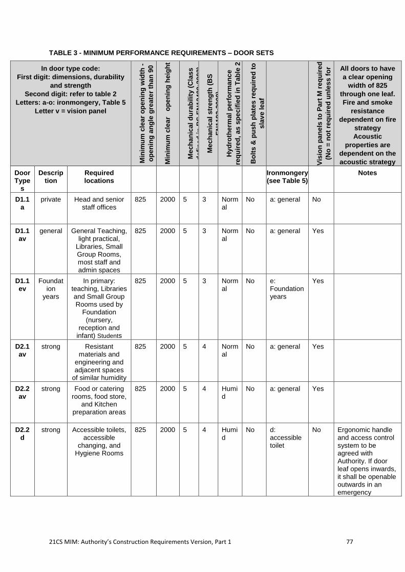
21CS MIM: Authority’s Construction Requirements Version, Part 1 77
TABLE 3 - MINIMUM PERFORMANCE REQUIREMENTS – DOOR SETS
In door type code:
First digit: dimensions, durability
and strength
Second digit: refer to table 2
Letters: a-o: ironmongery, Table 5
Letter v = vision panel
Min
imu
m c
lea
r o
pen
ing
wid
th -
op
en
ing
an
gle
gre
ate
r th
an
90
deg
ree
s is p
erm
itte
d
Min
imu
m c
lea
r o
pen
ing
heig
ht
Mech
an
ical d
ura
bilit
y (
Cla
ss
defi
ned
in
BS
EN
124
00:2
002)
Mech
an
ical
str
en
gth
(B
S
EN
11
92:2
000)
Hyd
roth
erm
al p
erf
orm
an
ce
req
uir
ed
, as
sp
ecif
ied
in
Tab
le 2
Bo
lts &
pu
sh
pla
tes r
eq
uir
ed
to
sla
ve le
af
Vis
ion
pan
els
to
Pa
rt M
re
qu
ired
(No
= n
ot
req
uir
ed
un
less
fo
r
fire
str
ate
gy)
All doors to have
a clear opening
width of 825
through one leaf.
Fire and smoke
resistance
dependent on fire
strategy
Acoustic
properties are
dependent on the
acoustic strategy
Door Type
s
Description
Required locations
Ironmongery (see Table 5)
Notes
D1.1a
private Head and senior staff offices
825 2000 5 3 Normal
No a: general No
D1.1av
general General Teaching, light practical,
Libraries, Small Group Rooms, most staff and admin spaces
825 2000 5 3 Normal
No a: general Yes
D1.1ev
Foundation
years
In primary: teaching, Libraries and Small Group Rooms used by
Foundation (nursery,
reception and infant) Students
825 2000 5 3 Normal
No e: Foundation years
Yes
D2.1av
strong Resistant materials and
engineering and adjacent spaces
of similar humidity
825 2000 5 4 Normal
No a: general Yes
D2.2av
strong Food or catering rooms, food store,
and Kitchen preparation areas
825 2000 5 4 Humid
No a: general Yes
D2.2d
strong Accessible toilets, accessible
changing, and Hygiene Rooms
825 2000 5 4 Humid
No d: accessible toilet
No Ergonomic handle and access control system to be agreed with Authority. If door leaf opens inwards, it shall be openable outwards in an emergency
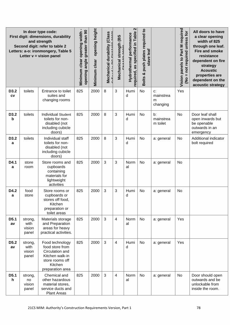
21CS MIM: Authority’s Construction Requirements Version, Part 1 78
In door type code:
First digit: dimensions, durability
and strength
Second digit: refer to table 2
Letters: a-o: ironmongery, Table 5
Letter v = vision panel
Min
imu
m c
lea
r o
pen
ing
wid
th -
op
en
ing
an
gle
gre
ate
r th
an
90
deg
ree
s is p
erm
itte
d
Min
imu
m c
lea
r o
pen
ing
heig
ht
Mech
an
ical d
ura
bilit
y (
Cla
ss
defi
ned
in
BS
EN
124
00:2
002)
Mech
an
ical
str
en
gth
(B
S
EN
11
92:2
000)
Hyd
roth
erm
al p
erf
orm
an
ce
req
uir
ed
, as
sp
ecif
ied
in
Tab
le 2
Bo
lts &
pu
sh
pla
tes r
eq
uir
ed
to
sla
ve le
af
Vis
ion
pan
els
to
Pa
rt M
re
qu
ired
(No
= n
ot
req
uir
ed
un
less
fo
r
fire
str
ate
gy)
All doors to have
a clear opening
width of 825
through one leaf.
Fire and smoke
resistance
dependent on fire
strategy
Acoustic
properties are
dependent on the
acoustic strategy
D3.2cv
toilets Entrance to toilet suites and
changing rooms
825 2000 8 3 Humid
No c: mainstream changing
Yes
D3.2b
toilets Individual Student toilets for non-disabled (not
including cubicle doors)
825 2000 8 3 Humid
No b: mainstream toilet
No Door leaf shall open inwards but be openable outwards in an emergency
D3.2a
toilets Individual staff toilets for non-disabled (not
including cubicle doors)
825 2000 8 3 Humid
No a: general No Additional indicator bolt required
D4.1a
store room
Store rooms and cupboards containing
materials for lightweight activities
825 2000 3 3 Normal
No a: general No
D4.2a
food store
Store rooms or cupboards or
stores off food, Kitchen
preparation or toilet areas
825 2000 3 3 Humid
No a: general No
D5.1av
strong, with
vision panel
Materials storage and Preparation areas for heavy
practical activities.
825 2000 3 4 Normal
No a: general Yes
D5.2av
strong, with
vision panel
Food technology food store from Circulation and Kitchen walk-in store rooms off
Kitchen preparation area
825 2000 3 4 Humid
No a: general Yes
D5.1h
strong, no
vision panel
Chemical and other hazardous material stores,
service ducts and Plant Areas
825 2000 3 4 Normal
No a: general No Door should open outwards and be unlockable from inside the room.
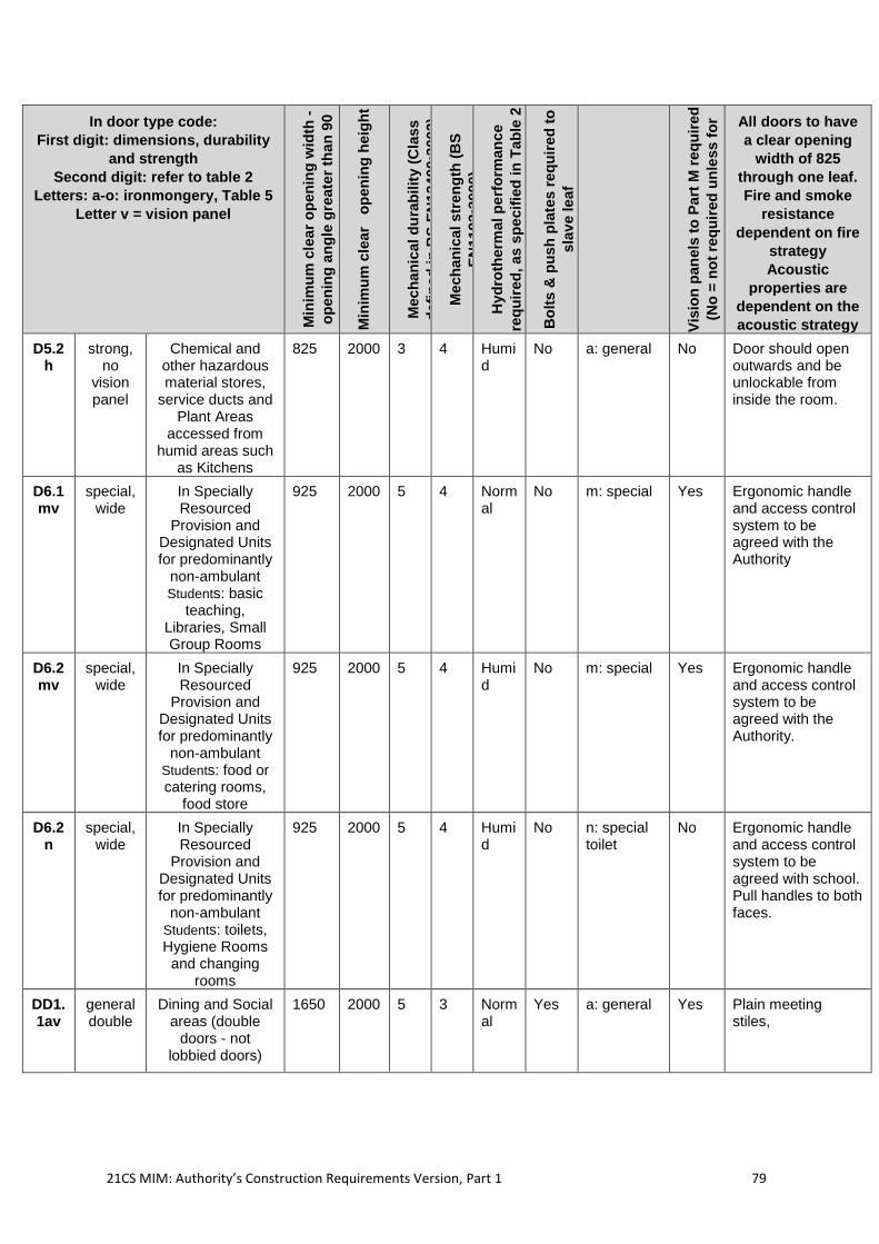
21CS MIM: Authority’s Construction Requirements Version, Part 1 79
In door type code:
First digit: dimensions, durability
and strength
Second digit: refer to table 2
Letters: a-o: ironmongery, Table 5
Letter v = vision panel
Min
imu
m c
lea
r o
pen
ing
wid
th -
op
en
ing
an
gle
gre
ate
r th
an
90
deg
ree
s is p
erm
itte
d
Min
imu
m c
lea
r o
pen
ing
heig
ht
Mech
an
ical d
ura
bilit
y (
Cla
ss
defi
ned
in
BS
EN
124
00:2
002)
Mech
an
ical
str
en
gth
(B
S
EN
11
92:2
000)
Hyd
roth
erm
al p
erf
orm
an
ce
req
uir
ed
, as
sp
ecif
ied
in
Tab
le 2
Bo
lts &
pu
sh
pla
tes r
eq
uir
ed
to
sla
ve le
af
Vis
ion
pan
els
to
Pa
rt M
re
qu
ired
(No
= n
ot
req
uir
ed
un
less
fo
r
fire
str
ate
gy)
All doors to have
a clear opening
width of 825
through one leaf.
Fire and smoke
resistance
dependent on fire
strategy
Acoustic
properties are
dependent on the
acoustic strategy
D5.2h
strong, no
vision panel
Chemical and other hazardous material stores,
service ducts and Plant Areas
accessed from humid areas such
as Kitchens
825 2000 3 4 Humid
No a: general No Door should open outwards and be unlockable from inside the room.
D6.1mv
special, wide
In Specially Resourced
Provision and Designated Units for predominantly
non-ambulant Students: basic
teaching, Libraries, Small Group Rooms
925 2000 5 4 Normal
No m: special Yes Ergonomic handle and access control system to be agreed with the Authority
D6.2mv
special, wide
In Specially Resourced
Provision and Designated Units for predominantly
non-ambulant Students: food or catering rooms,
food store
925 2000 5 4 Humid
No m: special Yes Ergonomic handle and access control system to be agreed with the Authority.
D6.2n
special, wide
In Specially Resourced
Provision and Designated Units for predominantly
non-ambulant Students: toilets, Hygiene Rooms
and changing rooms
925 2000 5 4 Humid
No n: special toilet
No Ergonomic handle and access control system to be agreed with school. Pull handles to both faces.
DD1.1av
general double
Dining and Social areas (double
doors - not lobbied doors)
1650 2000 5 3 Normal
Yes a: general Yes Plain meeting stiles,
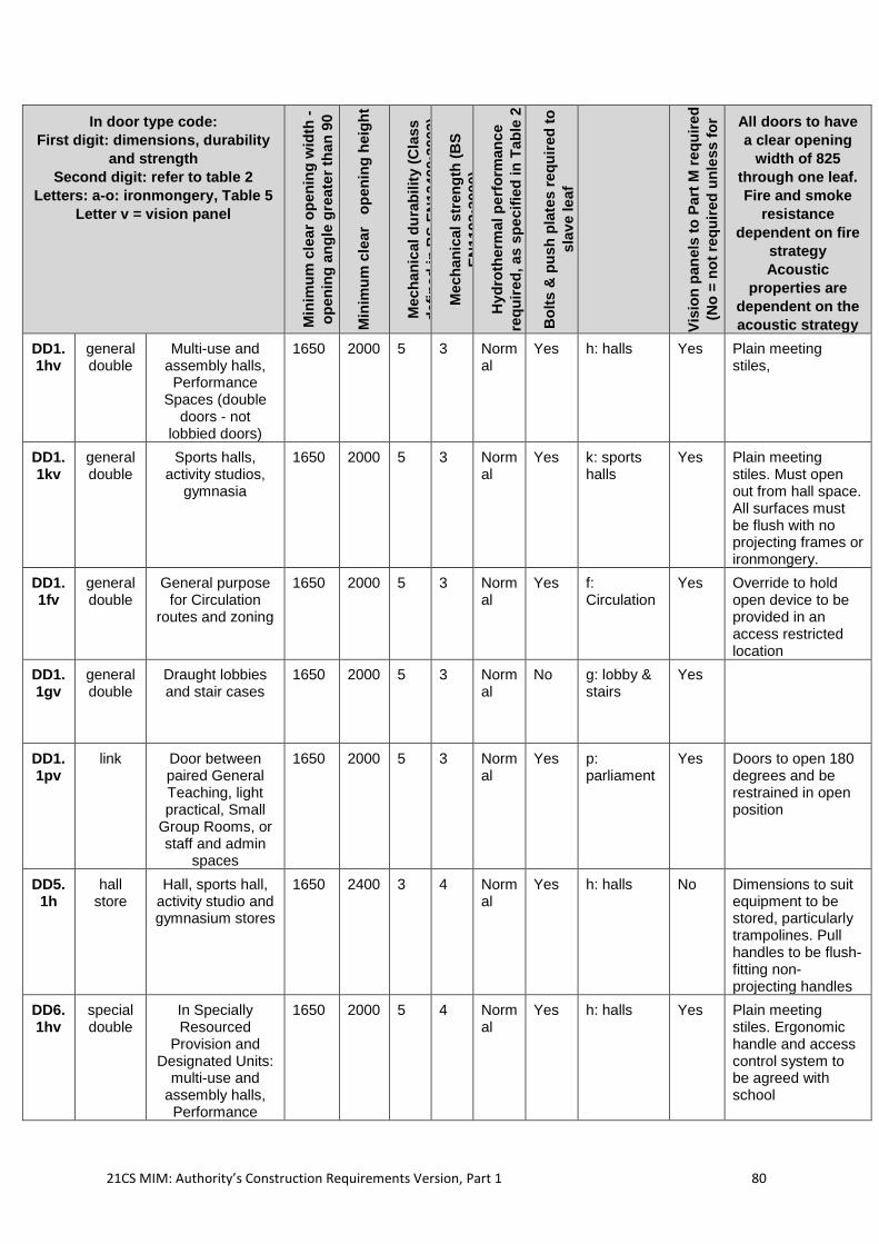
21CS MIM: Authority’s Construction Requirements Version, Part 1 80
In door type code:
First digit: dimensions, durability
and strength
Second digit: refer to table 2
Letters: a-o: ironmongery, Table 5
Letter v = vision panel
Min
imu
m c
lea
r o
pen
ing
wid
th -
op
en
ing
an
gle
gre
ate
r th
an
90
deg
ree
s is p
erm
itte
d
Min
imu
m c
lea
r o
pen
ing
heig
ht
Mech
an
ical d
ura
bilit
y (
Cla
ss
defi
ned
in
BS
EN
124
00:2
002)
Mech
an
ical
str
en
gth
(B
S
EN
11
92:2
000)
Hyd
roth
erm
al p
erf
orm
an
ce
req
uir
ed
, as
sp
ecif
ied
in
Tab
le 2
Bo
lts &
pu
sh
pla
tes r
eq
uir
ed
to
sla
ve le
af
Vis
ion
pan
els
to
Pa
rt M
re
qu
ired
(No
= n
ot
req
uir
ed
un
less
fo
r
fire
str
ate
gy)
All doors to have
a clear opening
width of 825
through one leaf.
Fire and smoke
resistance
dependent on fire
strategy
Acoustic
properties are
dependent on the
acoustic strategy
DD1.1hv
general double
Multi-use and assembly halls, Performance
Spaces (double doors - not
lobbied doors)
1650 2000 5 3 Normal
Yes h: halls Yes Plain meeting stiles,
DD1.1kv
general double
Sports halls, activity studios,
gymnasia
1650 2000 5 3 Normal
Yes k: sports halls
Yes Plain meeting stiles. Must open out from hall space. All surfaces must be flush with no projecting frames or ironmongery.
DD1.1fv
general double
General purpose for Circulation
routes and zoning
1650 2000 5 3 Normal
Yes f: Circulation
Yes Override to hold open device to be provided in an access restricted location
DD1.1gv
general double
Draught lobbies and stair cases
1650 2000 5 3 Normal
No g: lobby & stairs
Yes
DD1.1pv
link Door between paired General Teaching, light practical, Small
Group Rooms, or staff and admin
spaces
1650 2000 5 3 Normal
Yes p: parliament
Yes Doors to open 180 degrees and be restrained in open position
DD5.1h
hall store
Hall, sports hall, activity studio and gymnasium stores
1650 2400 3 4 Normal
Yes h: halls No Dimensions to suit equipment to be stored, particularly trampolines. Pull handles to be flush-fitting non-projecting handles
DD6.1hv
special double
In Specially Resourced
Provision and Designated Units:
multi-use and assembly halls, Performance
1650 2000 5 4 Normal
Yes h: halls Yes Plain meeting stiles. Ergonomic handle and access control system to be agreed with school
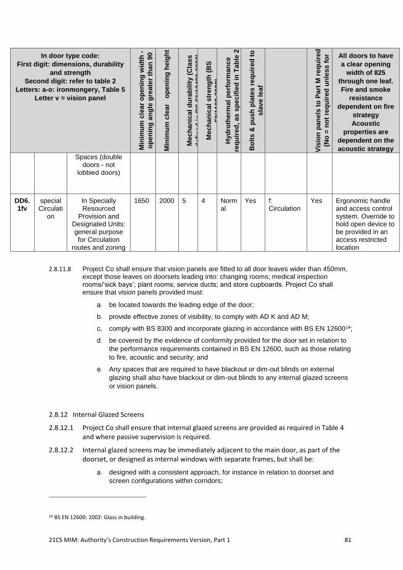
21CS MIM: Authority’s Construction Requirements Version, Part 1 81
In door type code:
First digit: dimensions, durability
and strength
Second digit: refer to table 2
Letters: a-o: ironmongery, Table 5
Letter v = vision panel
Min
imu
m c
lea
r o
pen
ing
wid
th -
op
en
ing
an
gle
gre
ate
r th
an
90
deg
ree
s is p
erm
itte
d
Min
imu
m c
lea
r o
pen
ing
heig
ht
Mech
an
ical d
ura
bilit
y (
Cla
ss
defi
ned
in
BS
EN
124
00:2
002)
Mech
an
ical
str
en
gth
(B
S
EN
11
92:2
000)
Hyd
roth
erm
al p
erf
orm
an
ce
req
uir
ed
, as
sp
ecif
ied
in
Tab
le 2
Bo
lts &
pu
sh
pla
tes r
eq
uir
ed
to
sla
ve le
af
Vis
ion
pan
els
to
Pa
rt M
re
qu
ired
(No
= n
ot
req
uir
ed
un
less
fo
r
fire
str
ate
gy)
All doors to have
a clear opening
width of 825
through one leaf.
Fire and smoke
resistance
dependent on fire
strategy
Acoustic
properties are
dependent on the
acoustic strategy
Spaces (double doors - not
lobbied doors)
DD6.1fv
special Circulati
on
In Specially Resourced
Provision and Designated Units: general purpose for Circulation
routes and zoning
1650 2000 5 4 Normal
Yes f: Circulation
Yes Ergonomic handle and access control system. Override to hold open device to be provided in an access restricted location
2.8.11.8 Project Co shall ensure that vision panels are fitted to all door leaves wider than 450mm, except those leaves on doorsets leading into: changing rooms; medical inspection rooms/‘sick bays’; plant rooms; service ducts; and store cupboards. Project Co shall ensure that vision panels provided must:
be located towards the leading edge of the door;
provide effective zones of visibility, to comply with AD K and AD M;
comply with BS 8300 and incorporate glazing in accordance with BS EN 1260014;
be covered by the evidence of conformity provided for the door set in relation to
the performance requirements contained in BS EN 12600, such as those relating
to fire, acoustic and security; and
Any spaces that are required to have blackout or dim-out blinds on external
glazing shall also have blackout or dim-out blinds to any internal glazed screens
or vision panels.
2.8.12 Internal Glazed Screens
2.8.12.1 Project Co shall ensure that internal glazed screens are provided as required in Table 4 and where passive supervision is required.
2.8.12.2 Internal glazed screens may be immediately adjacent to the main door, as part of the doorset, or designed as internal windows with separate frames, but shall be:
designed with a consistent approach, for instance in relation to doorset and
screen configurations within corridors;
14 BS EN 12600: 2002: Glass in building.
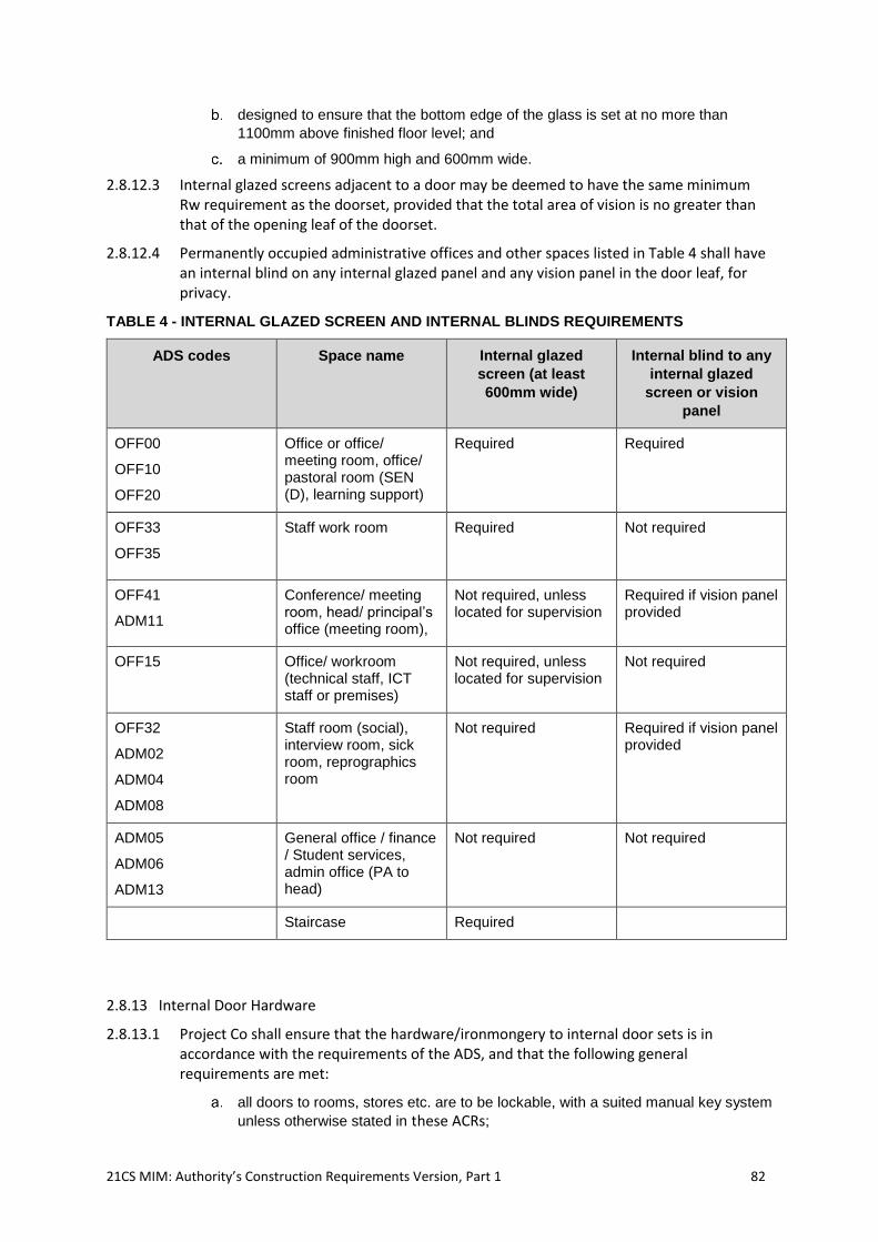
21CS MIM: Authority’s Construction Requirements Version, Part 1 82
designed to ensure that the bottom edge of the glass is set at no more than
1100mm above finished floor level; and
a minimum of 900mm high and 600mm wide.
2.8.12.3 Internal glazed screens adjacent to a door may be deemed to have the same minimum Rw requirement as the doorset, provided that the total area of vision is no greater than that of the opening leaf of the doorset.
2.8.12.4 Permanently occupied administrative offices and other spaces listed in Table 4 shall have an internal blind on any internal glazed panel and any vision panel in the door leaf, for privacy.
TABLE 4 - INTERNAL GLAZED SCREEN AND INTERNAL BLINDS REQUIREMENTS
ADS codes Space name Internal glazed
screen (at least
600mm wide)
Internal blind to any
internal glazed
screen or vision
panel
OFF00
OFF10
OFF20
Office or office/ meeting room, office/ pastoral room (SEN (D), learning support)
Required Required
OFF33
OFF35
Staff work room Required Not required
OFF41
ADM11
Conference/ meeting room, head/ principal’s office (meeting room),
Not required, unless located for supervision
Required if vision panel provided
OFF15 Office/ workroom (technical staff, ICT staff or premises)
Not required, unless located for supervision
Not required
OFF32
ADM02
ADM04
ADM08
Staff room (social), interview room, sick room, reprographics room
Not required Required if vision panel provided
ADM05
ADM06
ADM13
General office / finance / Student services, admin office (PA to head)
Not required Not required
Staircase Required
2.8.13 Internal Door Hardware
2.8.13.1 Project Co shall ensure that the hardware/ironmongery to internal door sets is in accordance with the requirements of the ADS, and that the following general requirements are met:
all doors to rooms, stores etc. are to be lockable, with a suited manual key system
unless otherwise stated in these ACRs;
21CS MIM: Authority’s Construction Requirements Version, Part 1 83
the detail of the locking and suiting requirements to individual rooms is agreed
with the Authority, and evidence of this is given to the Authority;
all hardware including door closers and door seals takes account of the age of the
Students operating the doors;
controlled (staff operated) emergency release locks should be provided for toilet
and shower cubicle doors, released from outside by hexagon or star key (not
coin-slot); and
nameplates and numbers are fitted to all internal doors. The detailed
requirements for individual rooms are described in the ADS.
2.8.13.2 Project Co shall ensure that the design and installation of hardware to door sets comply with the following requirements:
where ironmongery is provided, Project Co shall conform to the specifications in
Table 5, to match the relevant doorset code in the ADS;
the ironmongery shall be to the relevant specifications below and complement the
strength and durability classification of the doors to which they are fitted;
all hardware must provide functionality and performance appropriate to that door
set’s intended use and must not undermine the performance of the sets to which
they are fitted;
door leaves that are neither steel nor timber with laminated finish are provided
with protection plates that shall be sufficient to protect the doors from damage
from Mobility Equipment and, where relevant, trolleys. These shall be on both
sides of all door leaves and a minimum of 200mm high, or 450mm in any schools
with non-ambulant Specially Resourced Provision or Designated Unit Students;
push plates shall be provided to each door leaf on the face used to push the door
open. These shall be a minimum of 90mm x 1400mm in size, or if a single plate is
not compatible with other hardware fitted to the door, two minimum 90mm width
plates fitted above and below the lock position shall be provided to protect to an
equivalent extent;
anti-finger trap door profiles and hinges shall be fitted to all doors to teaching,
learning, and halls used by Foundation Phase Students, except where it is very
unlikely for Students to be present; and
where anti-finger trap fittings and profiles are required, both edges of the doors
shall be treated to prevent young children getting their fingers caught and injured.
The proposed solution shall not require frequent maintenance or replacement.
2.8.13.3 Door stops are fitted such that they prevent the door leaf damaging adjacent surfaces and prevent damage to the door leaf itself. They shall be fitted to adjacent skirting boards as close to the leading edge of the leaf as possible and not less than two thirds of the door width away from the hinge line. Stops must not be located in positions where they may constitute a trip hazard.
2.8.13.4 Project Co shall ensure that:
all ironmongery inside sports halls, activity and dance studios and other spaces
housing energetic physical activity shall be flush fitting;
accessible and staff WCs require a method of limiting access to staff and disabled
users only and which meets the requirements of AD M for limited dexterity;
door handles shall satisfy the requirements of BS 8300 ‘Design of buildings and
their approaches to meet the needs of disabled people’ to ensure they are
suitable for people with reduced manual dexterity or visual impairment;
21CS MIM: Authority’s Construction Requirements Version, Part 1 84
the server room shall be secured via a lock and key, of a type that cannot be
duplicated without authority;
six keys shall be provided for the server room at the Actual ICT Handover Date (1
x network manager, 1 x technician, 1 x site manager, 1 x Disaster Recovery plan
to be kept within the safe, and 2 x spare to be kept in a safe);
if there is more than one door to the server room, then both doors shall contain
suited locks so that a single key can open both doors;
reference shall be made to these ACRs for any additional requirements such as
access control or anti-finger trap fittings and profiles;
hinges must meet the requirements of BS EN 193515. Account should be taken of
any door closers that will affect the specification of the hinge;
2.8.13.5 locks shall be as listed in Table 5 as one of the following types:
lever lock – suitable for use with lever handles, operated by key from outside and
thumb-turn inside, note: Classroom locks are to be unlockable but not lockable from the
Classroom side;
dead lock – suitable for use without lever handles; in double doors the slave leaf will
require flush bolts to top and bottom;
bathroom lock – lock that can be locked from the inside by turn or lever and can be
released from outside by hexagon or star key (not coin-slot); and
ergonomic lock - as bathroom lock but operable by users with limited dexterity;
2.8.13.6 Locking arrangements for examination stores shall comply with relevant exam board criteria (Joint Council for Qualifications or equivalent) given in these ACRs.
2.8.13.7 Project Co shall ensure that door closers must meet the requirements of BS EN 115416 as well as the following additional requirements:
door closers (and door seals) must take account of the age of the Students
operating the doors;
the closer shall incorporate an adjustable tensioner which is set such that the
door provides optimum fire resistance and acoustic performance when closed
and as far as possible the operating forces are within the limit permitted in BS
8300;
any delayed action closers should not delay the closing action more than that
required for its use (for example, for the ease of disabled people). Where the
device is fitted to a fire door, this delay must not exceed 25 seconds, as specified
in BS EN 1154; and
any door closers fitted on fire door sets on Circulation routes must incorporate
electro-magnetic hold-open devices linked to (and compatible with) the automatic
fire detection and alarm system.
2.8.13.8 Project Co shall ensure that electro-magnetic hold-open devices must meet the requirements of BS EN 1155 and should not be fitted to door sets required to be self-closing in order to provide appropriate privacy, such as door sets to changing rooms. Electro-magnetic devices shall only be provided on self-closing fire doors, and only on
15 BS EN 1935: 2002: Building hardware. Single-axis hinges. 16 BS EN 1154: 1994: Building hardware. Controlled door closing devices.

21CS MIM: Authority’s Construction Requirements Version, Part 1 85
those devices which release automatically. Measures are taken to prevent accidental impact with the leading edge of the door leaf, when in the open position. Edges of all doors that stand open shall contrast visually with the surrounds, and protection of the leading edge of the door shall be provided to prevent the creation of a hazard.
2.8.13.9 Project Co shall ensure that lever handles must meet the requirements of BS EN 190617, be compatible with the locks with which they are to be used and satisfy the requirements of BS 8300: 2001 (to ensure they are suitable for people with reduced manual dexterity or visual impairment). Lever handles shall have a diameter of between 19mm and 35mm, be offset from the door leaf by at least 45mm, be at least 95mm long, have a return end, and contrast with the door leaf by a minimum of 20 LRV points. All lever handles shall have bolt-through fixings.
2.8.13.10 Project Co shall ensure that pull handles on doors meet the requirements of BS 8424 – ‘Building hardware. Pull handles. Requirements and test methods’. Pull handles shall have a diameter of between 19mm and 35mm, be offset from the door leaf by at least 45mm, be at least 400mm long, and contrast with the door leaf by a minimum of 20 LRV points. Additionally, pull handles must be located so their lower end is 1000mm above FFL or 1100mm above FFL if clashing with other door hardware. All pull handles shall have bolt-through fixings. Pull type handles shall not be fitted to the push side of doors.
2.8.13.11 Project Co shall ensure that any access control device shall:
be designed and installed to BS EN 60839 11 1: 2015;
not undermine the performance provided by the door sets on which they are
fitted;
not inhibit escape in the case of a fire or other emergency;
comply with relevant directives for electronic devices;
be able to be operated by disabled Facility Users;
offer appropriate durability;
offer the range of functionality required; and
be easily repairable or replaceable.
17 BS EN 1906:2010: Building hardware. Lever handles and knob furniture.
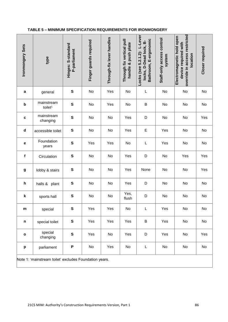
21CS MIM: Authority’s Construction Requirements Version, Part 1 86
TABLE 5 – MINIMUM SPECIFICATION REQUIREMENTS FOR IRONMONGERY
Iro
nm
on
gery
Sets
typ
e
Hin
ges:
S-s
tan
dard
P-p
arl
iam
en
t
Fin
ger
gu
ard
s r
eq
uir
ed
Th
rou
gh
-fix
leve
r h
an
dle
s
Th
rou
gh
fix
ve
rtic
al p
ull
han
dle
& p
ush
pla
te
Lo
cks (
se
e 5
.2.1
.2):
L
-Le
ver
locks,
D-D
ead
lo
ck,
B-
Bath
roo
m, E
-erg
on
om
ic
Sta
ff-o
nly
acc
es
s c
on
tro
l
syste
m
Ele
ctr
om
ag
neti
c h
old
op
en
devic
e r
eq
uir
ed
wit
h
overr
ide in
acc
ess
re
str
icte
d
locati
on
Clo
ser
req
uir
ed
a general S No Yes No L No No No
b mainstream
toilet1 S No Yes No B No No No
c mainstream
changing S No No Yes D No No Yes
d accessible toilet S No No Yes E Yes No No
e Foundation
years S Yes Yes No L Yes No No
f Circulation S No No Yes D No Yes Yes
g lobby & stairs S No No Yes None No No Yes
h halls & plant S No No Yes D No No No
k sports hall S No No Yes,
flush D No No No
m special S Yes Yes No L Yes No No
n special toilet S Yes Yes Yes B Yes No No
o special
changing S Yes No Yes D Yes No Yes
p parliament P No Yes No L No No No
Note 1: ‘mainstream toilet’ excludes Foundation years.
21CS MIM: Authority’s Construction Requirements Version, Part 1 87
2.8.14 Floors
2.8.15 Floor Structure
2.8.15.1 Project Co shall limit floor vibration and sound transmission.
2.8.15.2 To eliminate the risk of “bouncy” floors, all floors must consist of a composite screeded construction, and must meet the following vibration criteria:
all Basic Teaching spaces, staff and admin areas office and any Circulation to
these areas are limited to a minimum fundamental natural frequency of 5Hz or
justified by other means (e.g. response factors or analysis as described in the SCI
publication P354 -Design of Floors for Vibration: A New Approach); and
any Halls, drama spaces, studios or areas that may be subjected to unusual
vibration characteristics are justified through calculation and/or justification using
SCI P354 or other similar industry standard documentation.
flanking paths shall be identified in the BB93 acoustic report and adequate
structural isolation provided;
2.8.15.3 Rooftop playdecks and MUGAs shall be designed to minimise stucture borne vibration and airborne sound transmission to occupied rooms. A specialist structural and acoustic report is required to prove there is adequate structural isolation and attenuation of sound and vibration.
2.8.16 Floor Finishes18
2.8.16.1 Project Co shall ensure that the choice and installation of floor finishes comply with the following requirements in all internal areas of the Buildings, in addition to any required in these ACRs:
durability: able to maintain its characteristics and performance for at least 5 years
under normal conditions;
resilience: able to support the furniture and equipment listed in the Legacy
Equipment survey summary and Facility-Specific ADS; withstand pedestrian
traffic without undue deformation or permanent marking; able to accommodate
thermal and structural movement in both the finish and the sub-floor;
continuity: having minimal joints, and flush joints between different finishes;
cleaning - the ease and frequency of cleaning is taken into account, as well as the
level of hygiene required;
suitability - the finish including texture and colour is suitable for the age and
needs of Students including those with SEN (D); and
safety - including slip resistance where specified in the ADS
2.8.16.2 Project Co shall ensure that the floor finishes conform to the performance specifications set out in the five types of floor finish in the technical annex of the ADS, taking account of all British and European standards relevant to the material type and where there is
18 Project Co to note that some aspects of finishes such as colour are likely to be subject to the review procedure in Schedule 8 of this Agreement but that the Range of Finishes submitted under Schedule 8 of this Agreement will need to continue to comply with these ACR provisions.
21CS MIM: Authority’s Construction Requirements Version, Part 1 88
under-floor heating, floor finishes are able to withstand the effects of temperatures up to 27˚C. (ref BS 8203, CP 1018, BS EN 14041)19.
2.8.16.3 Project Co shall ensure that the floor finish is appropriate to the activities taking place in the space it serves, and any particular needs of the Students, in terms of:
cleanliness - all finishes must as a minimum achieve a basic level i.e. be non-
porous, reasonably joint free (ceramic tile with epoxy-based grout and carpet tiles
are both acceptable), with smooth welds in sheet materials; those rated ‘high’
within Table 6 shall have no dirt traps and shall incorporate coved skirting;
smoothness- with minimal abrasion characteristics against the skin;
sound absorption and transmission- ensuring good acoustic properties and
performance floor finishes should be considered as a whole alongside other
internal surfaces to achieve the performance criteria specified in BB93;
impact resistance;
slip resistance- ensuring minimal tripping hazards;
chemical and heat resistance- where the need is identified in the ADS;
static resistance- where the need is identified in the ADS, for example in the
server room;
area elastic performance of A3 or A4 in sports or activity spaces;
durability- to BS EN ISO 10874: 2012;
suitability for Mobility Equipment users and others with a physical disability or
sensory impairment;
colour and pattern – in terms of maintenance, way-finding and in Specially
Resourced Provision and Designated Units, sensitivity; and
having a low Volatile Organic Compounds (VOC) finish.
2.8.16.4 Project Co shall provide and maintain suitable barrier matting at external entrances in order to remove dirt and moisture from the soles of shoes and wheeled traffic to assist with cleanliness of internal floor coverings. The draft lobby to the main Facility entrance shall have as a minimum: a 2.1m length of barrier matting in the direction of travel, in compliance with BS 7953:
in entrances where high levels of ingress are expected (e.g. main Student
entrance), Project Co shall demonstrate that the extent of barrier matting provided
is based on an analysis of use; and
barrier matting shall be provided to any external doors in Foundation Phase
Classrooms.
2.8.16.5 Barrier matting shall also:
not present a hazard to the user in normal use and not become slippery when
wet;
remove and retain moisture and dirt, preventing it being transferred to internal
floor coverings;
be of a ‘heavy duty’ type, catering for high flow rates at key times within the Core
Day;
19 BS 8203: 2001: Code of Practice for the installation of resilient floor coverings. BS EN 14041: 2004: Resilient, textile and laminate floor coverings.
21CS MIM: Authority’s Construction Requirements Version, Part 1 89
be of a recessed or floor fixed type, except at external doors to Foundation Phase
Classrooms where loose mats with a non-slip backing are permitted; and
not impede the movement of Mobility Equipment or non-ambulant Facility Users.
2.8.16.6 For any server room and hub rooms provided, Project Co shall provide anti-static flooring and all extraneous metal parts, including door frames, shall be electrically earth bonded.
2.8.16.7 Where retractable bleacher seating is provided, the floor finish shall be capable of carrying the weight of this equipment, with special attention paid to sprung floor construction loading abilities, and the point loads imposed by rollers used. The floor finish shall be homogenous, if vinyl, and shall be capable of resisting wear associated with this equipment.
2.8.16.8 Where timber floor finishes are provided they shall be finished with a 2-pack polyurethane flexible lacquer/sealant (no acrylic mixes).
2.8.16.9 where vinyl, lino or other surface sheet material is to be laid, the surface onto which the sheet is to be fixed shall be free of surface irregularities in line with BS 8203:2017 to standard SR1 set out in this British Standard; and in addition, trowel lines, adhesive comb lines, indentations, manufacturing and construction joints including volumetric module joints (where all these joints are not intended movement joints) shall not be visible or identifiable through the sheet covering when construction is complete.
2.8.16.10 All floors in General Teaching rooms and Circulation areas in Primary Schools shall be finished in lino, rubber, or vinyl in line with Table 6. Project Co shall supply for each General Teaching room a 3 x 3m carpet square mat with a weighted and ramped edging in order to minimise trip hazards.
2.8.16.11 All floors in Secondary Schools and College General Teaching rooms and Circulation areas shall be finished in carpet, lino, rubber, or vinyl in line with Table 6.
2.8.16.12 In Table 6, there are three levels of water resistance required, defined as follows:
water resistance 1 - to withstand a reasonable degree of spillage and dampness
from footwear etc;
water resistance 2 - to allow frequent spillage or wetting without damage, staining
or absorption. Requirements for resilience covered in BS EN 661 1995 and BS
EN 662 1995; and
water resistance 3 - to allow regular wetting without damage, staining or
absorption. Requirements for spreading of water covered in BS EN 661 1995 and
BS EN 13553 for vinyl in wet areas.
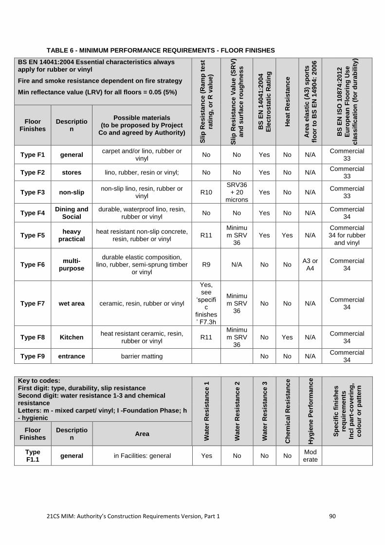
21CS MIM: Authority’s Construction Requirements Version, Part 1 90
TABLE 6 - MINIMUM PERFORMANCE REQUIREMENTS - FLOOR FINISHES
BS EN 14041:2004 Essential characteristics always apply for rubber or vinyl
Fire and smoke resistance dependent on fire strategy
Min reflectance value (LRV) for all floors = 0.05 (5%)
Slip
Re
sis
tan
ce (
Ra
mp
te
st
rati
ng
, o
r R
va
lue)
Slip
Re
sis
tan
ce V
alu
e (
SR
V)
an
d s
urf
ac
e r
ou
gh
ne
ss
BS
EN
1404
1:2
00
4
Ele
ctr
osta
tic R
ati
ng
Heat
Re
sis
tan
ce
Are
a e
lasti
c (
A3)
sp
ort
s
flo
or
to B
S E
N 1
490
4:
20
06
BS
EN
IS
O 1
0874:2
012
Eu
rop
ean
Flo
ori
ng
Us
e
cla
ssif
icati
on
(fo
r d
ura
bilit
y)
Floor Finishes
Description
Possible materials (to be proposed by Project
Co and agreed by Authority)
Type F1 general carpet and/or lino, rubber or
vinyl No No Yes No N/A
Commercial 33
Type F2 stores lino, rubber, resin or vinyl; No No Yes No N/A Commercial
33
Type F3 non-slip non-slip lino, resin, rubber or
vinyl R10
SRV36 + 20
microns Yes No N/A
Commercial 33
Type F4 Dining and
Social durable, waterproof lino, resin,
rubber or vinyl No No Yes No N/A
Commercial 34
Type F5 heavy
practical heat resistant non-slip concrete,
resin, rubber or vinyl R11
Minimum SRV
36 Yes Yes N/A
Commercial 34 for rubber
and vinyl
Type F6 multi-
purpose
durable elastic composition, lino, rubber, semi-sprung timber
or vinyl R9 N/A No No
A3 or A4
Commercial 34
Type F7 wet area ceramic, resin, rubber or vinyl
Yes, see
‘specific
finishes’ F7.3h
Minimum SRV
36 No No N/A
Commercial 34
Type F8 Kitchen heat resistant ceramic, resin,
rubber or vinyl R11
Minimum SRV
36 No Yes N/A
Commercial 34
Type F9 entrance barrier matting No No N/A Commercial
34
Key to codes: First digit: type, durability, slip resistance Second digit: water resistance 1-3 and chemical resistance Letters: m - mixed carpet/ vinyl; I -Foundation Phase; h - hygienic
Wate
r R
esis
tan
ce 1
Wate
r R
esis
tan
ce 2
Wate
r R
esis
tan
ce 3
Ch
em
ica
l R
esis
tan
ce
Hyg
ien
e P
erf
orm
an
ce
Sp
ecif
ic f
inis
he
s
req
uir
em
en
ts
Incl p
art
-co
veri
ng
,
co
lou
r o
r p
att
ern
Floor Finishes
Description
Area
Type F1.1
general in Facilities: general Yes No No No Moderate
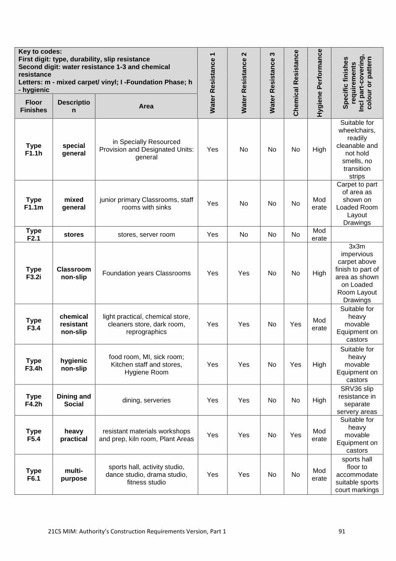
21CS MIM: Authority’s Construction Requirements Version, Part 1 91
Key to codes: First digit: type, durability, slip resistance Second digit: water resistance 1-3 and chemical resistance Letters: m - mixed carpet/ vinyl; I -Foundation Phase; h - hygienic
Wate
r R
esis
tan
ce 1
Wate
r R
esis
tan
ce 2
Wate
r R
esis
tan
ce 3
Ch
em
ica
l R
esis
tan
ce
Hyg
ien
e P
erf
orm
an
ce
Sp
ecif
ic f
inis
he
s
req
uir
em
en
ts
Incl p
art
-co
veri
ng
,
co
lou
r o
r p
att
ern
Floor Finishes
Description
Area
Type F1.1h
special general
in Specially Resourced Provision and Designated Units:
general Yes No No No High
Suitable for wheelchairs,
readily cleanable and
not hold smells, no transition
strips
Type F1.1m
mixed general
junior primary Classrooms, staff rooms with sinks
Yes No No No Moderate
Carpet to part of area as shown on
Loaded Room Layout
Drawings
Type F2.1
stores stores, server room Yes No No No Moderate
Type F3.2i
Classroom non-slip
Foundation years Classrooms Yes Yes No No High
3x3m impervious
carpet above finish to part of area as shown
on Loaded Room Layout
Drawings
Type F3.4
chemical resistant non-slip
light practical, chemical store, cleaners store, dark room,
reprographics Yes Yes No Yes
Moderate
Suitable for heavy
movable Equipment on
castors
Type F3.4h
hygienic non-slip
food room, MI, sick room; Kitchen staff and stores,
Hygiene Room Yes Yes No Yes High
Suitable for heavy
movable Equipment on
castors
Type F4.2h
Dining and Social
dining, serveries Yes Yes No No High
SRV36 slip resistance in
separate servery areas
Type F5.4
heavy practical
resistant materials workshops and prep, kiln room, Plant Areas
Yes Yes No Yes Moderate
Suitable for heavy
movable Equipment on
castors
Type F6.1
multi-purpose
sports hall, activity studio, dance studio, drama studio,
fitness studio Yes Yes No No
Moderate
sports hall floor to
accommodate suitable sports court markings
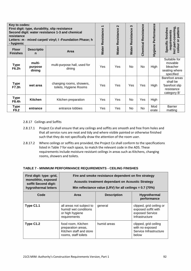
21CS MIM: Authority’s Construction Requirements Version, Part 1 92
Key to codes: First digit: type, durability, slip resistance Second digit: water resistance 1-3 and chemical resistance Letters: m - mixed carpet/ vinyl; I -Foundation Phase; h - hygienic
Wate
r R
esis
tan
ce 1
Wate
r R
esis
tan
ce 2
Wate
r R
esis
tan
ce 3
Ch
em
ica
l R
esis
tan
ce
Hyg
ien
e P
erf
orm
an
ce
Sp
ecif
ic f
inis
he
s
req
uir
em
en
ts
Incl p
art
-co
veri
ng
,
co
lou
r o
r p
att
ern
Floor Finishes
Description
Area
Type F6.2h
multi-purpose dining
multi-purpose hall, used for dining
Yes Yes No No High
Suitable for movable bleacher
seating where specified
Type F7.3h
wet area changing rooms, showers,
toilets, Hygiene Rooms Yes Yes Yes Yes High
Barefoot areas shall be
'barefoot slip resistance category B'
Type F8.4h
Kitchen Kitchen preparation Yes Yes No Yes High
Type F9.2
entrance entrance lobbies Yes Yes No No Moderate
Barrier matting
2.8.17 Ceilings and Soffits
2.8.17.1 Project Co shall ensure that any ceilings and soffits are smooth and free from holes and that all service runs are neat and tidy and where visible painted or otherwise finished such that they do not specifically draw the attention of the room user.
2.8.17.2 Where ceilings or soffits are provided, the Project Co shall conform to the specifications listed in Table 7 for each space, to match the relevant code in the ADS. These requirements include moisture resistant ceilings in areas such as Kitchens, changing rooms, showers and toilets.
TABLE 7 - MINIMUM PERFORMANCE REQUIREMENTS - CEILING FINISHES
First digit: type: grid,
monolithic, exposed
soffit Second digit:
hygrothermal letters
Fire and smoke resistance dependent on fire strategy
Acoustic treatment dependant on Acoustic Strategy
Min reflectance value (LRV) for all ceilings = 0.7 (70%)
Code Area Description Hygrothermal performance
Type C1.1 all areas not subject to humid/ wet conditions or high hygiene requirements
general clipped, grid ceiling or exposed soffit with exposed Service Infrastructure
Type C1.2 food room, Kitchen preparation areas, Kitchen staff and store rooms, staff toilets
humid areas clipped, grid ceiling with no exposed Service Infrastructure below
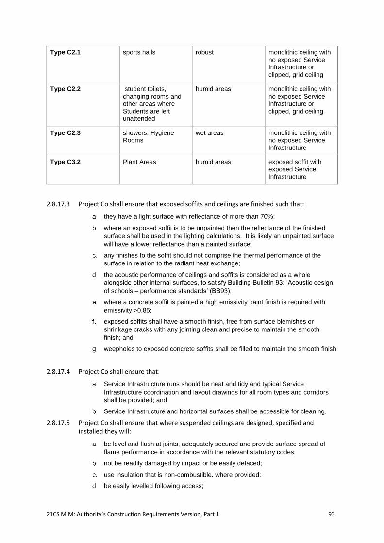
21CS MIM: Authority’s Construction Requirements Version, Part 1 93
Type C2.1 sports halls robust monolithic ceiling with no exposed Service Infrastructure or clipped, grid ceiling
Type C2.2 student toilets, changing rooms and other areas where Students are left unattended
humid areas monolithic ceiling with no exposed Service Infrastructure or clipped, grid ceiling
Type C2.3 showers, Hygiene Rooms
wet areas monolithic ceiling with no exposed Service Infrastructure
Type C3.2 Plant Areas humid areas exposed soffit with exposed Service Infrastructure
2.8.17.3 Project Co shall ensure that exposed soffits and ceilings are finished such that:
they have a light surface with reflectance of more than 70%;
where an exposed soffit is to be unpainted then the reflectance of the finished
surface shall be used in the lighting calculations. It is likely an unpainted surface
will have a lower reflectance than a painted surface;
any finishes to the soffit should not comprise the thermal performance of the
surface in relation to the radiant heat exchange;
the acoustic performance of ceilings and soffits is considered as a whole
alongside other internal surfaces, to satisfy Building Bulletin 93: ‘Acoustic design
of schools – performance standards’ (BB93);
where a concrete soffit is painted a high emissivity paint finish is required with
emissivity >0.85;
exposed soffits shall have a smooth finish, free from surface blemishes or
shrinkage cracks with any jointing clean and precise to maintain the smooth
finish; and
weepholes to exposed concrete soffits shall be filled to maintain the smooth finish
2.8.17.4 Project Co shall ensure that:
Service Infrastructure runs should be neat and tidy and typical Service
Infrastructure coordination and layout drawings for all room types and corridors
shall be provided; and
Service Infrastructure and horizontal surfaces shall be accessible for cleaning.
2.8.17.5 Project Co shall ensure that where suspended ceilings are designed, specified and installed they will:
be level and flush at joints, adequately secured and provide surface spread of
flame performance in accordance with the relevant statutory codes;
not be readily damaged by impact or be easily defaced;
use insulation that is non-combustible, where provided;
be easily levelled following access;
21CS MIM: Authority’s Construction Requirements Version, Part 1 94
be easy to maintain; and
have a low VOC finish.
2.8.17.6 Project Co shall provide moisture resistant ceilings in areas such as Kitchens, changing rooms, showers and toilets, as specified in the ADS.
2.8.17.7 Ceilings for unsupervised spaces such as WC and shower cubicles shall be continuous and monolithic or suspended with clips to keep tiles in place and to prevent unwanted access. Ceilings in areas that are supervised such as changing rooms and wash hand basin areas can be suspended in type, subject to moisture resistance criteria being satisfied.
2.8.17.8 Project Co shall ensure that ceilings within toilets and changing rooms are robust, moisture resistant, easy to clean and inaccessible to Students.
2.8.17.9 Ceiling finishes in Kitchen and food room areas should be capable of being cleaned to maintain a hygienic finish with no dirt traps.
2.8.17.10 Where equipment or plant is located within a false ceiling, a suitable, robust, permanent means of access for maintenance is provided.
2.8.17.11 In Specially Resourced Provision and Designated Units, Project Co must comply with the following additional requirements, where specified in the relevant Site Specific Brief:
where specified in the ADS, ceilings are robust and inaccessible to Students;
where ceiling-mounted hoists or physiotherapy equipment are provided, tracking
shall be coordinated with other ceiling Service Infrastructure and the ceiling
structure is able to support the equipment and the person using the equipment;
and
where specified in the ADS, ceilings in medical treatment rooms are
homogeneous with recessed light fitting;
2.8.18 Decorations and Finishes
2.8.18.1 Project Co shall comply with the wall and floor finishes specified in the ADS. Project Co will need to consider acoustic properties and noise reduction capabilities in line with paragraph 2.9.67 when choosing wall and floor finishes.
2.8.18.2 Project Co shall ensure that decoration and finishes:
fulfil the requirements in the ADS;
take account of safety and fitness for purpose;
are suitable for the activities taking place in the area, and for the age and any
special needs of the occupants;
are able to withstand heavy usage and potential Malicious Damage typical of a
School or College (as relevant)
Light surface marking to be removed using warm water and mild detergent only.
Special cleaners or solvents should not be required to remove normal marking
but may be used to remove graffiti such as permanent marker.;
are resilient to impact and minimise noise;
are easy to clean and maintain;
contribute to the level and quality of light in a space and ensure visual comfort,
concrete soffits are painted white; and
shall have VOC limits that comply with Schedule 2 of the The Volatile Organic
Compounds in Paints, Varnishes and Vehicle Refinishing Products Regulations
2012, SI 1715, 2012. For example, water-borne one pack performance coatings
21CS MIM: Authority’s Construction Requirements Version, Part 1 95
shall have a maximum VOC content of 140g/l of ready to use product in
accordance with The Volatile Organic Compounds in Paints, Varnishes and
Vehicle Refinishing Products Regulations 2012, SI 1715, 2012..
2.8.18.3 Project Co shall also take account of the requirements of Students with SEN (D) and all those with disabilities, such as providing suitable colour schemes, textures and contrasts on walls, floors, stairs and doors to assist those with visual impairments to orientate themselves. Where children are especially vulnerable to infection, all surfaces shall be smooth and easy to clean to minimise the collection of dust and pathogens. Any specific requirements are given in the relevant Site Specific Brief.
2.8.18.4 Project Co shall ensure that all surfaces are appropriately prepared and smooth prior to the application of decoration and finishes and that decoration and finishes are not left in a rough, unfinished condition following completion of the Works.
2.8.18.5 Additionally, Project Co shall ensure that external finishes shall:
be durable and resistant to weathering; and
enable the easy removal of graffiti; and internal finishes should contribute to the
level and quality of light in a space.
2.8.18.6 Project Co shall take account of the requirements of Students with SEN (D) and all those with disabilities, such as providing suitable colour schemes, textures and contrasts on walls, floors, stairs and doors to assist those with visual impairments to orientate themselves. In Specially Resourced Provision and Designated Units, where children are especially vulnerable to infection, all surfaces shall be smooth and easy to clean to minimise the collection of dust and pathogens. Anti-bacterial coatings may be necessary in places where there are children with health problems. Any specific requirements are given in the SSB.
2.8.18.7 Project Co shall ensure that minimum surface reflectance levels are to be as follows:
Walls: 0.5;
Painted and exposed soffits and ceilings in new or existing areas: 0.7; and
Floor: 0.05 and not higher than 0.4 to avoid scuff marks. Where areas of the room
are carpeted the average surface reflectance of the floor can be reduced.
2.8.18.8 Daylight and visual amenity calculations should include light reflectance values for the actual floor finish chosen and for horizontal reflective surfaces, which can be of higher reflectance than the floor.
2.8.18.9 Project Co shall consider that lighter surface finishes will improve the visual quality of the space and will aid in delivering daylight deeper into the rooms where lit from one side.
2.8.18.10 For any analysis undertaken in relation to daylight the 70/50/50 reflectance’s shall be used unless alternative reflectance’s are known at the time of the design. The preference is always to use actual reflectance’s in place of the 70/50/50 criteria. Floor reflectance and desk reflectance can be combined for daylight calculations; however, the combined reflectance for a carpeted room shall not exceed 20%.
2.8.18.11 Project Co shall ensure that the 60° gloss factor of window sills, furniture and flooring is less than 15%. This information shall be sourced from the manufacturers of the window sills, furniture or floor coverings.
2.8.18.12 Project Co shall ensure that ceiling and wall brightness is adequate to allow for visual comfort. In order to achieve this, ceilings should be lit such that the ceiling luminance is at least 30% of the illuminance on work surfaces. The light on the ceiling shall be delivered from a combination of direct and reflected light. Walls should be lit such that
21CS MIM: Authority’s Construction Requirements Version, Part 1 96
the wall illuminance is at least 50% of the illuminance on the work surfaces. Light Reflectance Values (LRV) shall comply with the requirement for 30 percentage points of difference in contrast between foreground and background for visual orientation of pupils with visual impairments in accordance with Equality Act AD M
2.8.18.13 Where circumstances preclude the use of water-based paints, Project Co shall ensure that appropriate risk assessments and method statements are prepared and submitted to the Authority prior to the Actual Completion Date for all paints and coatings to ensure the safety of Students, staff, visitors and operatives who may be exposed to solvents and water-borne and solvent-borne materials.
2.8.18.14 Project Co shall ensure that decorations and finishes in Circulation spaces:
are robust enough to withstand the impact of normal daily impact by Students’
bags and shoes;
are robust enough to withstand regular cleaning;
the design of the walls in the Circulation spaces shall allow for touching up or for
sections of wall to be maintained without the need to carry out works to the full
wall to maintain an acceptable finish. For example corridor lengths can be split
into manageable bays with dado rails, movement joints, expressed joints, etc or a
type of finish can be chosen which allows for small areas to be repainted without
spoiling the overall appearance of the wall;
are water-borne unless use of solvent-borne finishes for particular uses are
agreed with the Authority;
heavy duty areas are classed as the walls within reach of Students (ie, up to at
least 1.2m height for Primary Schools and 1.5m for Secondary Schools and
colleges) in the following areas: corridors, stairways, student entrances and
reception areas, halls, drama rooms, dining queues, science, DT, art, vocational
spaces and stores.
finishes in heavy duty areas shall be easy to clean. They shall be capable of
achieving the minimum decoration cycle of 5 years in Table 1before first repaint.
The minimum expected standard of performance of the wall finish in heavy duty
areas shall be as:
a. Dulux , Crown or Johnstones: high performance, durable trade acrylic
eggshell, single pack clear or coloured protective performance coating or
single pack protective performance glaze over the manufacturer’s
approved base;
b. approved trade performance coating;
c. approved durable high performance wall finish;
d. a trade high performance easily cleanable durable acrylic matt finish if
agreed with the employer;
all colours should be agreed with the Authority. Brilliant white should be avoided
in main corridor areas and replaced with either an off white, or colour as agreed
with the Authority;
normal duty areas are those areas not classed as heavy duty. Normal duty areas
shall be finished in a minimum of a trade high performance matt acrylic paint;
where water-based paints are used there shall be a minimum requirement for wall
paints to be tested under BS EN 13300 and gain a class 1 classification using the
BS EN ISO 11998 test method or a class C classification using the BS 7719 test
method;
21CS MIM: Authority’s Construction Requirements Version, Part 1 97
In areas subject to humidity such as changing rooms mould resistant finishes
shall be used;and
No products shall be used that require disposal of excess paint or solvent used in
cleaning at hazardous waste sites. All empty cans should be recycled using the
appropriate can-recycling scheme through the applicable paint merchant.
2.8.18.15 Corners that are exposed in heavy duty areas, and on columns, shall be protected with upvc or stainless steel corners glued to the substrate. Where there are graphics on the wall transparent corner pieces may be needed.
2.8.18.16 In Table 8, there are three levels of finish specified, which are defined as follows:
Finish 1 - impervious - able to resist the penetration of water, solutions containing
detergents, disinfectants and other liquids likely to be encountered in School or
College buildings;
Finish 2 - jointless / flush impervious joints - without joints, or having joints that
are sealed by methods which make the whole surface impervious and prevent the
collection of dirt and bacteria; and
Finish 3 - smooth - no coarser than brush-applied matt emulsion paint on a flat
plastered surface without projections, indents or holes part-way through the
material.
2.8.18.17 Project Co shall refer to the SSB for any additional requirements for Students with SEN (D), such as colour or texture and may seek paint manufacturer assistance for colour schemes.
2.8.19 Basin splashbacks
2.8.19.1 A splashback or an upstand shall be provided to a minimum height of 300mm above all basins, wash troughs and sinks, and shall be formed from water resistant, cleanable, and durable materials.
2.8.20 Workmanship
2.8.20.1 High performance primers shall be used on corner edge beading of plastered walls.
2.8.20.2 The painting contractor shall apply the dry wall sealing primer coat to all plasterboard walls, not the plastering contractor.
2.8.20.3 NBS M60 paint finish specifications shall be certified as suitable by the paint manufacturer and shall be accompanied by full manufacturers paint specifications. Manufacturers’ specifications shall include information that shall be included in the Building Users Guide on the means of day to day cleaning and removal of graffiti and more stubborn marks. This shall include the types of sponges/cloths/wipes and solvents that can be used.
2.8.20.4 Manufacturers specifications shall include instructions for repair of damage such as gouges and scratches and loss of sheen due to cleaning of stubborn marks. The finishing schedules shall include mist out and bring forward filled areas. Mist or primer coat to be a suitable product to compliment the top coats in-line with manufacturers’ guidelines for standard plasterboard substrates or a fully dry board and skimmed surface. PVA shall not be used to seal plasterboard surfaces for painting.
2.8.20.5 Where surface spread of flame needs to be controlled, generally providing a Class O fire rating, refurbishment projects shall have a flake test carried out by the paint manufacturer to determine if the fire resistance of the paint finish requires a specialist flame retardant coating system to be applied.
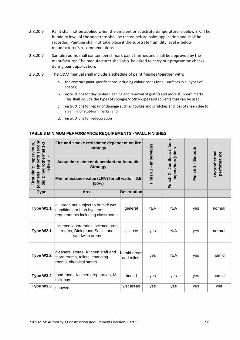
21CS MIM: Authority’s Construction Requirements Version, Part 1 98
2.8.20.6 Paint shall not be applied when the ambient or substrate temperature is below 8oC. The humidity level of the substrate shall be tested before paint application and shall be recorded. Painting shall not take place if the substrate humidity level is below maunfacturer’s recommendations.
2.8.20.7 Sample rooms shall contain benchmark paint finishes and shall be approved by the manufacturer. The manufacturer shall also be asked to carry out programme checks during paint application.
2.8.20.8 The O&M manual shall include a schedule of paint finishes together with:
the contract paint specifications including colour codes for all surfaces in all types of
spaces;
instructions for day to day cleaning and removal of graffiti and more stubborn marks.
This shall include the types of sponges/cloths/wipes and solvents that can be used;
instructions for repair of damage such as gouges and scratches and loss of sheen due to
cleaning of stubborn marks; and
instructions for redecoration
TABLE 8 MINIMUM PERFORMANCE REQUIREMENTS - WALL FINISHES
Fir
st
dig
it:
imp
erv
iou
s,
join
tless,
sm
oo
th s
eco
nd
dig
it:
hyg
roth
erm
al
1-3
lett
ers
: -
Fire and smoke resistance dependent on fire
strategy F
inis
h 1
- Im
pe
rvio
us
Fin
ish
2 -
Jo
intl
ess /
flu
sh
imp
erv
iou
s jo
ints
Fin
ish
3 -
Sm
oo
th
Hyg
roth
erm
al
perf
orm
an
ce
Acoustic treatment dependant on Acoustic
Strategy
Min reflectance value (LRV) for all walls = 0.5
(50%)
Type Area Description
Type W1.1 all areas not subject to humid/ wet
conditions or high hygiene
requirements including classrooms
general N/A N/A yes normal
Type W2.1
science laboratories, science prep
rooms, Dining and Social and
sandwich areas
science yes N/A yes normal
Type W2.2 cleaners’ stores, Kitchen staff and
store rooms, toilets, changing
rooms, chemical stores
humid areas
and toilets yes N/A yes humid
Type W3.2 food room, Kitchen preparation, MI,
sick bay humid yes yes yes humid
Type W3.3 showers wet areas yes yes yes wet
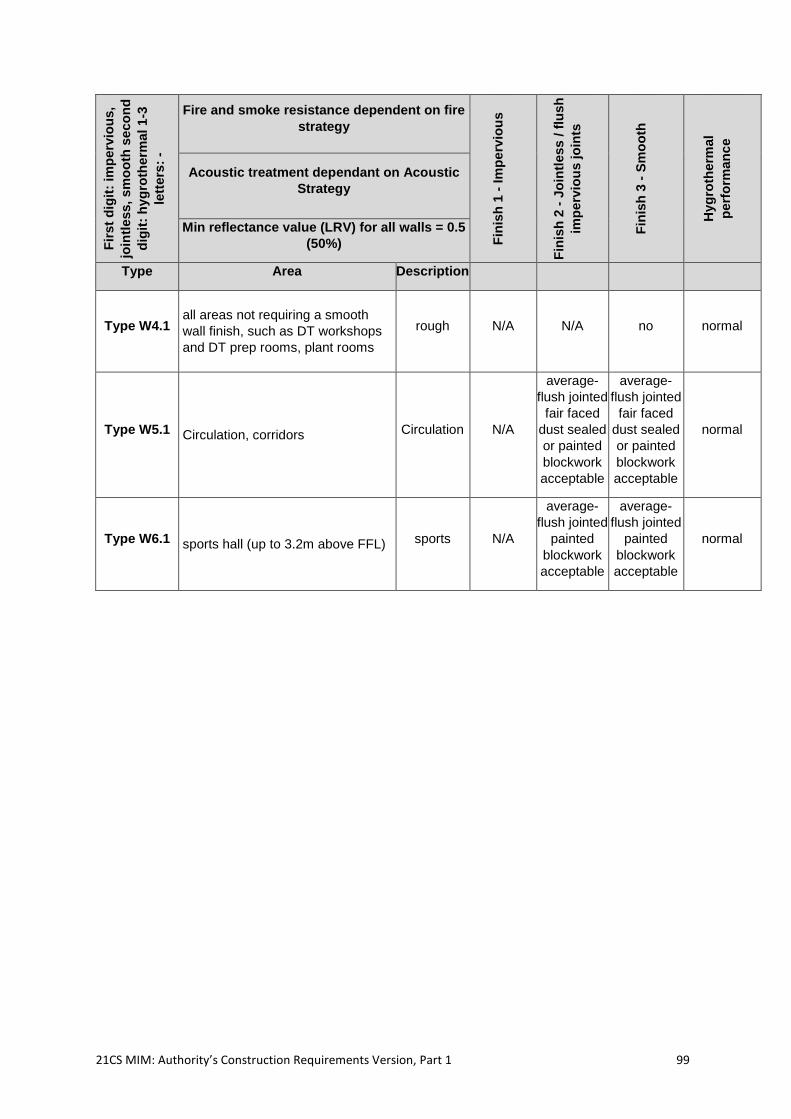
21CS MIM: Authority’s Construction Requirements Version, Part 1 99
Fir
st
dig
it:
imp
erv
iou
s,
join
tless,
sm
oo
th s
eco
nd
dig
it:
hyg
roth
erm
al
1-3
lett
ers
: -
Fire and smoke resistance dependent on fire
strategy
Fin
ish
1 -
Im
pe
rvio
us
Fin
ish
2 -
Jo
intl
ess /
flu
sh
imp
erv
iou
s jo
ints
Fin
ish
3 -
Sm
oo
th
Hyg
roth
erm
al
perf
orm
an
ce
Acoustic treatment dependant on Acoustic
Strategy
Min reflectance value (LRV) for all walls = 0.5
(50%)
Type Area Description
Type W4.1 all areas not requiring a smooth
wall finish, such as DT workshops
and DT prep rooms, plant rooms
rough N/A N/A no normal
Type W5.1 Circulation, corridors Circulation N/A
average-
flush jointed
fair faced
dust sealed
or painted
blockwork
acceptable
average-
flush jointed
fair faced
dust sealed
or painted
blockwork
acceptable
normal
Type W6.1 sports hall (up to 3.2m above FFL) sports N/A
average-
flush jointed
painted
blockwork
acceptable
average-
flush jointed
painted
blockwork
acceptable
normal
21CS MIM: Authority’s Construction Requirements Version, Part 1 100
2.9 Indoor Environmental Requirements
2.9.1 Project Co shall ensure that the design of the internal environmental conditions of all spaces meet the requirements in these ACRs, Building Bulletin 93: ‘Acoustic design of schools – performance standards’ (BB93) and the requirements within this section.
2.9.2 Project Co shall ensure that the design provides suitable, comfortable environmental conditions for all occupied spaces, including good lighting with optimum use of daylight, good air quality and acoustics, unobstructed ventilation and suitable temperatures throughout the year.
2.9.3 Project Co shall ensure that there is an appropriate level of local control over ventilation, heating, glare and light levels, and the needs of very young and vulnerable children and young people shall be taken into account.
2.9.4 Project Co shall develop the environmental design strategy in parallel with planning the Site and designing each Building's form and fabric to deliver comfort to the Facility Users in both winter and summer. Project Co shall employ an integrated design approach which takes account of local site conditions and exploits natural resources like daylight, ground temperature, night time air temperature, solar energy, rainfall and wind. Project Co shall choose environmental strategies that are appropriate for the level of expertise of the Facility Users and the Facility Premises Team.
2.9.5 In Designated Units or Specially Resourced Provision, Project Co shall take account of the particular needs of the Students, as specified in the relevant Site Specific Brief. For example, some children may be more sensitive to light or to infection or need higher levels of sound insulation.
2.9.6 Project Co shall ensure that internal spaces and engineering systems shall be designed and constructed to meet the ADS, ACRs, Availability Standards and other Service Level Specification requirements including the PIU Targets for light quality, room temperatures, ventilation and indoor air quality, acoustics, described in the Services Level Specification, Annex 1, and energy efficiency and functionality requirements so that all spaces are available and fit for purpose.
2.9.7 Daylight and lighting
2.9.7.1 Project Co shall ensure that the quality of light provided supports a positive teaching and learning environment. Project Co shall ensure that any lighting system provided:
creates a sufficient, effective and pleasant visual environment whilst minimising
glare;
meets the needs of Students with SEN (D) as required in these ACRs;
exploits energy saving opportunities without compromising the quality of the
visual environment; and
employs low maintenance solutions.
2.9.7.2 These criteria shall be read in conjunction any additional requirements in these ACRs.
21CS MIM: Authority’s Construction Requirements Version, Part 1 101
2.9.7.3 Project Co shall ensure that the lighting design complies with Law and Part L20 and takes account of best practice guidance21 and Good Industry Practice. In addition, Project Co shall ensure that the design provides good visibility for all teaching activities, in particular for whole class presentations using the whiteboard, which is one of the most demanding visual tasks. Project Co’s design shall provide that the visual environment is under the control of the teacher and light shading devices and dimming controls are important to achieve this.
2.9.7.4 Project Co shall ensure that the design:
integrates the design of daylight and electric light to provide a comfortable
environment and minimise energy use;
provides controls for daylight and electric light to suit activities and control glare,
that are easy to use and effective;
provides ways of controlling the effects of direct sunlight, to create a balance of
useful internal illuminance in the teaching space and avoid excessive
summertime overheating;
provides ways of allowing the whiteboard to be viewed clearly and without
reflections whilst retaining a space which is predominantly daylit;
provides ceiling and wall brightness adequate for good visual comfort;
provides an electrical lighting solution which creates a bright ambient lighting level
and in particular good lighting levels on the faces of the teachers and Students;
provides views from occupied rooms to the outside or, where this is not possible,
across an internal space (without obstructions) to a distance of at least 10m to
help avoid eye strain;
incorporates energy efficient lighting and controls to reduce energy use; and
includes emergency lighting, where specified in the relevant Site Specific Brief.
2.9.8 Daylight Design
2.9.8.1 Project Co shall optimise the Building form and orientation with respect to daylight provision, views out and views of the sky. In doing this the design should maximise the number of spaces where daylight is provided from two or more sides, or by roof lights, since it is possible for these spaces to be substantially daylit for the majority of the Academic Year.
2.9.8.2 In rooms with single sided daylighting it may be necessary to increase the ceiling heights and window head heights to achieve the daylight performance specified below.
2.9.8.3 If the room must be extended in depth, then secondary daylight from an atrium or rooflight will be required and/or the room height will need to be increased with a higher percentage of glazing used.
2.9.8.4 Window heads must be no more than 200mm from the finished head to the underside of the ceiling or soffit.
2.9.8.5 Project Co shall ensure that the annual provision of daylight in a space is to be predicted directly using climate-based daylight modelling (CBDM) as described in Section 3.3.1 of LG522, or similar methods that take into account the effects of direct and indirect sunlight
20 Part L, AD L2A and AD L2B, and The Non-domestic Building Services Compliance Guide. 21 Lighting Guide 5 (LG 5): Lighting for Education, available from the society of Light and Lighting. 22 Lighting Guide 5 (LG 5): Lighting for Education, available from the society of Light and Lighting.
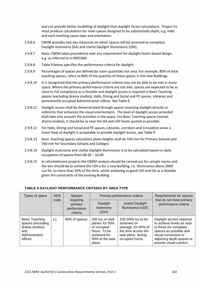
21CS MIM: Authority’s Construction Requirements Version, Part 1 102
and can provide better modelling of daylight than daylight factor calculations. Project Co must produce calculations for main spaces designed to be substantially daylit, e.g. Halls and each teaching space type and orientation.
2.9.8.6 CBDM provides two key measures on which spaces will be accessed as compliant. Daylight Autonomy (DA) and Useful Daylight Illuminance (UDI).
2.9.8.7 Note: CBDM takes precedence over any requirement for daylight factor-based design, e.g. as referred to in BREEAM.
2.9.8.8 Table 9 below specifies the performance criteria for daylight.
2.9.8.9 Percentages of spaces are defined by room quantities not area. For example, 80% of total teaching spaces, refers to 80% of the quantity of these spaces in the new Buildings.
2.9.8.10 It is recognised that the primary performance criteria may not be able to be met in every space. Where the primary performance criteria are not met, spaces are expected to be as close to full compliance as is feasible and daylight access is required in Basic Teaching spaces (excluding drama studios), Halls, Dining and Social and PE spaces, Libraries and permanently occupied Administration offices. See Table 9.
2.9.8.11 Daylight access shall be demonstrated through spaces receiving daylight directly or indirectly that enhances the visual environment. The level of daylight access provided shall take into account the activities in the space. For Basic Teaching spaces (except drama studios), it should be as near the DA and UDI levels quoted as possible.
2.9.8.12 For Halls, Dining and Social and PE spaces, Libraries, corridors and Circulation areas a lower level of daylight is acceptable to provide daylight access, see Table 9
2.9.8.13 Basic Teaching spaces calculation plane heights shall be 550 mm for Primary Schools and 700 mm for Secondary Schools and Colleges.
2.9.8.14 Daylight Autonomy and Useful Daylight Illuminance is to be calculated based on daily occupation of spaces from 08:30 – 16:00.
2.9.8.15 In refurbishment projects the CBDM analysis should be carried out for sample rooms and the aim should be to achieve the UDI-e for a new Building, i.e. illuminance above 2000 Lux for no more than 20% of the time, whilst achieving as good UDI and DA as is feasible given the constraints of the Existing Building.
TABLE 9 DAYLIGHT PERFORMANCE CRITERIA BY AREA TYPE
Types of space ADS
code
Spaces
requiring
primary
performance
criteria
Primary performance criteria Requirements for spaces
that do not meet primary
performance criteria Daylight
Autonomy
(sDA)
Useful Daylight
Illuminance (UDI)
Basic Teaching spaces (excluding drama studios); and Administration offices
L1 80% of spaces 300 lux on task planes for 50% of occupied hours. To be achieved for 50% of the task plane.
100-3000 lux to be achieved on average, for 80% of the time across the task plane, during occupied hours.
Daylight access required to achieve levels as near to those for compliant spaces as possible and visual connection to adjoining daylit spaces to provide visual comfort.
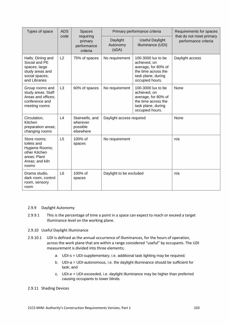
21CS MIM: Authority’s Construction Requirements Version, Part 1 103
Types of space ADS
code
Spaces
requiring
primary
performance
criteria
Primary performance criteria Requirements for spaces
that do not meet primary
performance criteria Daylight
Autonomy
(sDA)
Useful Daylight
Illuminance (UDI)
Halls; Dining and Social and PE spaces; large study areas and social spaces; and Libraries
L2 75% of spaces No requirement 100-3000 lux to be achieved, on average, for 80% of the time across the task plane, during occupied hours.
Daylight access
Group rooms and study areas; Staff Areas and offices; conference and meeting rooms
L3 60% of spaces No requirement 100-3000 lux to be achieved, on average, for 80% of the time across the task plane, during occupied hours.
None
Circulation, Kitchen preparation areas; changing rooms
L4 Stairwells, and wherever possible elsewhere
Daylight access required None
Store rooms; toilets and Hygiene Rooms; other Kitchen areas; Plant Areas; and kiln rooms
L5 100% of spaces
No requirement n/a
Drama studio, dark room, control room, sensory room
L6 100% of spaces
Daylight to be excluded n/a
2.9.9 Daylight Autonomy
2.9.9.1 This is the percentage of time a point in a space can expect to reach or exceed a target illuminance level on the working plane.
2.9.10 Useful Daylight Illuminance
2.9.10.1 UDI is defined as the annual occurrence of illuminances, for the hours of operation, across the work plane that are within a range considered “useful” by occupants. The UDI measurement is divided into three elements;
UDI-s = UDI-supplementary, i.e. additional task lighting may be required;
UDI-a = UDI-autonomous, i.e. the daylight illuminance should be sufficient for
task; and
UDI-e = UDI-exceeded, i.e. daylight illuminance may be higher than preferred
causing occupants to lower blinds.
2.9.11 Shading Devices
21CS MIM: Authority’s Construction Requirements Version, Part 1 104
2.9.11.1 Project Co shall also ensure that the design allows for the following:
blinds or other means of solar glare and daylight control shall be provided to all
exterior glazing (including rooflights) in all Basic Teaching spaces, Learning
Resource Areas and Staff Areas (L1, L2 & L3). The type of blind(s) employed will
be dependent on factors such as window orientation, daylight performance and
visual environment requirements of each space. The blinds shall not adversely
affect the ventilation of the space. Blinds are expected to be used in either a fully
up or fully down (undeployed or fully deployed) by the user for the purposes of
glare control, and the Daylight modelling calculations undertaken by the Project
Co shall reflect this, i.e. partially drawn blinds will not be allowed. For horizontal or
vertical adjustable blinds, the calculations may assume that the blinds are
deployed and set to allow glare free useful daylight penetration;
external shading devices such as brise soleil, overhangs, louvres or vertical fins,
and/or an internal blind solution such as venetian, vertical or roller blinds (screen,
blackout, etc.) are acceptable. However vertical blinds shall not be used in
teaching areas or any areas generally accessible to Students as they can be
easily damaged;
roller blinds should not be used to control glare where the window facing, or
orientation receives direct sunlight during the occupied part of the Core Day, and
where deployment will block out useful daylight. Where roller blinds are used, the
material shall be a screen (dim-out) type with a total visible light transmittance of
5-7%. The exception to this requirement is given below. In rooms where the
blinds are for solar glare control, i.e., not north facing Classrooms, the openness
of the weave of the material shall not be greater than 3%;
blinds can have a higher overall transmission and a higher openness or can be
excluded, if Project Co can demonstrate that the visual environment will be
adequate. The primary method of demonstration is by showing that the glazing
orientation is within 15 degrees of absolute North and all visual display equipment
in the space can achieve a contrast ratio of at least 3000:1. Alternatively Project
Co may provide a disability glare analysis to justify the choice of blinds with a
higher transmission or the exclusion of blinds on a particular façade;
roller blinds shall be provided in science laboratories and science studios to allow
for black-out for experiments. They shall have a maximum transmittance of 5%, a
maximum openness of 1% and side tracks to limit light spillage at the edges of
the blinds. Alternatively, black-out blinds with no side runners may be used if they
oversail the opening;
sports halls require solar glare control. Where there are rooflights, the use of a
diffusive glass is an acceptable alternative to blinds as long as Project Co
coordinates the rooflight layout with the layout of the sports courts and provides a
disability glare assessment to show that the rooflights are positioned to avoid
solar glare (e.g. they are located between badminton courts);
drama studios may be daylit as long as it is possible to exclude daylight using
blackout blinds or curtains;
window ventilation openings should not be obstructed by blinds or curtains when
these are opened;
where dim-out blinds are required, they should provide a suitable daylight
illuminance in the space and should not restrict ventilation;
where acoustic panels are placed in the room then the panels shall not negatively
interfere with the daylight distribution and in particular they shall not restrict the
distribution of daylight to the rear of the room; and
sports halls and main halls shall be day-lit.
21CS MIM: Authority’s Construction Requirements Version, Part 1 105
2.9.12 Glare
2.9.12.1 Project Co shall ensure that the design minimizes glare as this is very important for accomplishing difficult visual tasks such as viewing whiteboards or projected images and for viewing screens. Project Co shall ensure that the design enables control of daylight glare on computer monitors, whiteboards and projection screens and to ensure that the teacher or speaker need not face glare sources or be seen against a glare source. If this is not done the familiar “blinds down - lights on” scenario will result in poor visibility, high lighting energy consumption and minimal use of daylight.
2.9.12.2 Project Co shall also take account of any special requirements that Students may have, such as having a visual impairment.
2.9.12.3 Project Co shall ensure that the design of the space should first take into account the position of the whiteboard, smart board or projector. The daylight design and control of the daylight should then respond to the display equipment positions and the viewing angles of the Students. Project Co shall meet the requirements for day-lighting and shall not provide a “blinds down, lights on solution”.
2.9.12.4 In designing the Building, Project Co shall also consider the following and advise the Authority and each School Entity in the case of a School(s) project] on the type of equipment to purchase and the limitations of Legacy Equipment:
the intensity and contrast ratio of the smart board or projector will play a big role
in the clarity and comfort for the viewer. Equally the viewing angle is critical;
the brighter the screen, the higher the ambient lighting can be before blinds need
to be closed. However, brighter screens generally mean more powerful lamps
with consequent increases in energy consumption. For new installations, the
brightness of the screen when presented with a white image should be in the
range of 300 to 600 cd/m2. The brightness from any seated viewing position in
the room should not be less than 300 cd/m2. The diffuse and specular properties
of the screen material need to be carefully considered to ensure that there is not
a direct view of the light source which would wash out the image, nor that the
brightness and clarity of the surface reduces with acute viewing angles;
for existing installations, the brightness may be as low as 50-80 cd/m2 and the
preference would be to replace the Legacy Equipment. If this is not possible,
control of the daylight and ambient light needs to be considered to ensure the
presentation is not washed out and unclear; and
the contrast ratio of new equipment should be at least 3000:1.
2.9.12.5 Project Co shall ensure that wherever possible, to improve visual contrast, ceilings are to be light coloured and window frames, bars and reveals are to be light coloured or white and splayed. A light colour would be in the range of reflectance of 0.7 to 1.0. The window wall in particular should be light in colour.
2.9.13 Internal lighting systems
2.9.13.1 An interior lighting system shall be provided in accordance with the criteria given in these ACRs.
2.9.13.2 Where Unified Glare Rating (UGRL) calculations are not possible, compliance shall be demonstrated through luminaire intensity being limited to 3000 cd/m2 above 65 degrees from a downward vertical.
2.9.13.3 In Basic Teaching spaces, Learning Resource Areas and storage areas, surfaces shall be illuminated in accordance with Table 11 below.
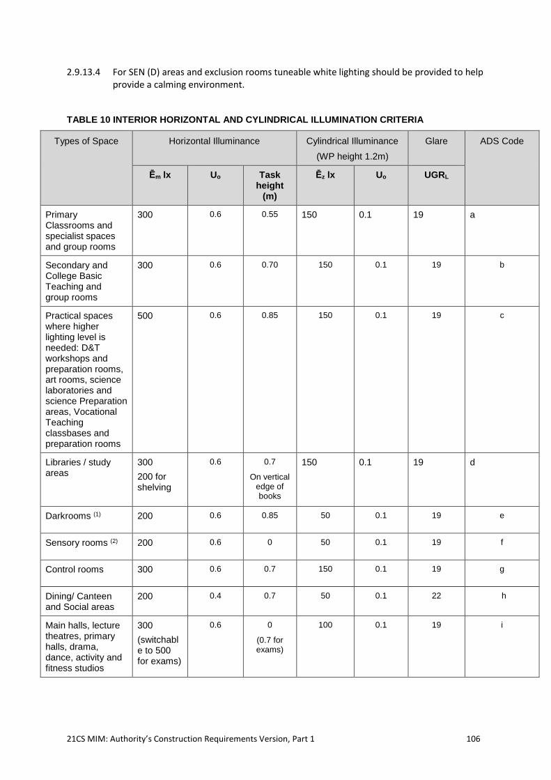
21CS MIM: Authority’s Construction Requirements Version, Part 1 106
2.9.13.4 For SEN (D) areas and exclusion rooms tuneable white lighting should be provided to help provide a calming environment.
TABLE 10 INTERIOR HORIZONTAL AND CYLINDRICAL ILLUMINATION CRITERIA
Types of Space Horizontal Illuminance Cylindrical Illuminance
(WP height 1.2m)
Glare ADS Code
Ēm lx Uo Task height
(m)
Ēz lx Uo UGRL
Primary Classrooms and specialist spaces and group rooms
300 0.6 0.55 150 0.1 19 a
Secondary and College Basic Teaching and group rooms
300 0.6 0.70 150 0.1 19 b
Practical spaces where higher lighting level is needed: D&T workshops and preparation rooms, art rooms, science laboratories and science Preparation areas, Vocational Teaching classbases and preparation rooms
500 0.6 0.85 150 0.1 19 c
Libraries / study areas
300
200 for shelving
0.6 0.7
On vertical edge of books
150 0.1 19 d
Darkrooms (1) 200 0.6 0.85 50 0.1 19 e
Sensory rooms (2) 200 0.6 0 50 0.1 19 f
Control rooms 300 0.6 0.7 150 0.1 19 g
Dining/ Canteen and Social areas
200 0.4 0.7 50 0.1 22 h
Main halls, lecture theatres, primary halls, drama, dance, activity and fitness studios
300
(switchable to 500 for exams)
0.6 0
(0.7 for exams)
100 0.1 19 i
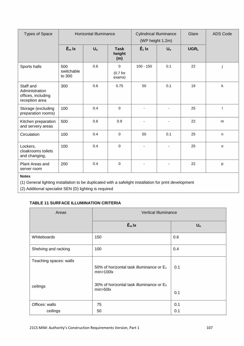
21CS MIM: Authority’s Construction Requirements Version, Part 1 107
Types of Space Horizontal Illuminance Cylindrical Illuminance
(WP height 1.2m)
Glare ADS Code
Ēm lx Uo Task height
(m)
Ēz lx Uo UGRL
Sports halls 500 switchable to 300
0.6 0
(0.7 for exams)
100 - 150 0.1 22 j
Staff and Administration offices, including reception area
300 0.6 0.75 50 0.1 19 k
Storage (excluding preparation rooms)
100 0.4 0 - - 25 l
Kitchen preparation and servery areas
500 0.6 0.9 - - 22 m
Circulation 100 0.4 0 50 0.1 25 n
Lockers, cloakrooms toilets and changing,
100 0.4 0 - - 25 o
Plant Areas and server room
200 0.4 0 - - 22 p
Notes
(1) General lighting installation to be duplicated with a safelight installation for print development
(2) Additional specialist SEN (D) lighting is required
TABLE 11 SURFACE ILLUMINATION CRITERIA
Areas Vertical Illuminance
Ēm lx Uo
Whiteboards 150 0.6
Shelving and racking 100 0.4
Teaching spaces: walls
ceilings
50% of horizontal task illuminance or Ev
min>100lx
30% of horizontal task illuminance or Eh
min>50lx
0.1
0.1
Offices: walls
ceilings
75
50
0.1
0.1
21CS MIM: Authority’s Construction Requirements Version, Part 1 108
Circulation: walls
ceilings
50
30
0.1
0.1
2.9.13.5 Project Co shall ensure that the maintained illuminance levels should comply with CIBSE Lighting Guide 5 (LG5): Lighting for Education. Calculations of the maintained illuminance shall utilise maintenance factors which are relative to the relevant Site, the rooms, the luminaires and the lamps selected. Default software maintenance factors shall not be used simply to avoid calculating the actual figures.
2.9.13.6 Project Co shall ensure that the ceiling is illuminated in accordance with CIBSE LG5 and recessed luminaires are avoided. Within corridors vertical illuminance should also be considered as detailed within Table 11 above.
2.9.13.7 Project Co shall ensure that luminaire layouts are co-ordinated with ceiling and structural planning grids to facilitate the relocation of partition walls within each Suite of Spaces. Switches are easily reconfigurable, and luminaires easily repositioned.
2.9.13.8 Project Co shall also design the Building so that:
teacher’s boards shall be adequately lit to ensure good visibility when used for
whole class presentation;
the number of different types of luminaires shall be limited to ease maintenance;
and
lighting should not be located over pools, where it is difficult and costlier to repair
and replace.
2.9.13.9 Where higher levels of illuminance are identified in the ADS or relevant Site Specific Briefs for more visually demanding tasks, such as for office desks, task lighting should be provided, wherever possible. Task lighting includes a ceiling recessed, surface or suspended luminaire dedicated to a particular task, a floor standing luminaire local to the task or a table mounted luminaire local to the task.
2.9.13.10 Where a number of functions take place in the same space Project Co shall ensure that the lighting is suitable for the range of activities specified. Where the activities have conflicting lighting requirements, priority should be given to the main function of the space. The lighting solution within larger spaces should add to the visual aesthetics of the environment along with achieving the required lighting levels.
2.9.13.11 Project Co shall provide switching for sports halls where some activities require higher lighting levels so as to achieve both higher and lower lighting levels and the default shall be the lower level.
2.9.13.12 Project Co shall supply cages to all electrical equipment in areas where impact from sports games is likely.
2.9.14 Lighting Efficiency
2.9.14.1 Project Co shall produce Lighting Energy Numeric Indicator (LENI) predictions for the energy performance of the Buildings in accordance with the methodology described in BS EN 1519323 with a total LENI for all internal lighting and separate LENI calculations for each of the room types identified in the ADS and SoA. The LENI prediction figures form the basis for auditing the energy performance and consumption of the internal lighting
23 BS EN 15193: 2007 – energy performance of buildings – energy requirements for lighting.
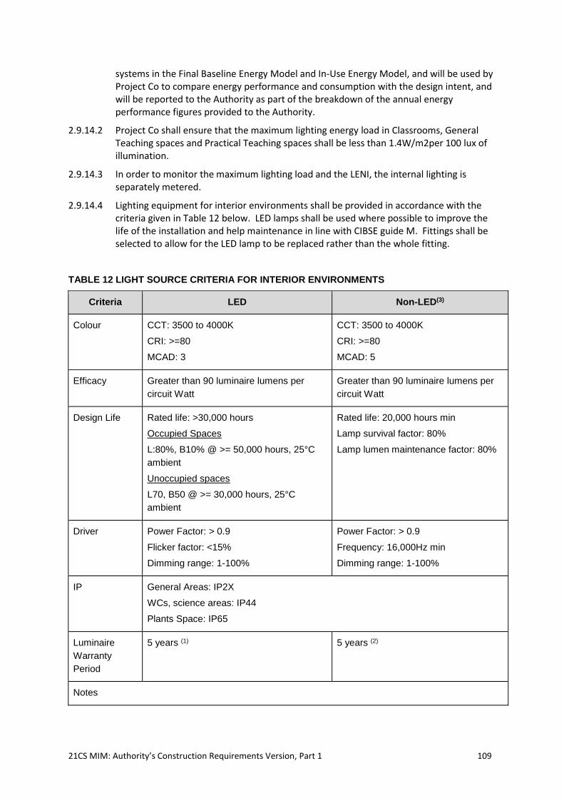
21CS MIM: Authority’s Construction Requirements Version, Part 1 109
systems in the Final Baseline Energy Model and In-Use Energy Model, and will be used by Project Co to compare energy performance and consumption with the design intent, and will be reported to the Authority as part of the breakdown of the annual energy performance figures provided to the Authority.
2.9.14.2 Project Co shall ensure that the maximum lighting energy load in Classrooms, General Teaching spaces and Practical Teaching spaces shall be less than 1.4W/m2per 100 lux of illumination.
2.9.14.3 In order to monitor the maximum lighting load and the LENI, the internal lighting is separately metered.
2.9.14.4 Lighting equipment for interior environments shall be provided in accordance with the criteria given in Table 12 below. LED lamps shall be used where possible to improve the life of the installation and help maintenance in line with CIBSE guide M. Fittings shall be selected to allow for the LED lamp to be replaced rather than the whole fitting.
TABLE 12 LIGHT SOURCE CRITERIA FOR INTERIOR ENVIRONMENTS
Criteria LED Non-LED(3)
Colour CCT: 3500 to 4000K
CRI: >=80
MCAD: 3
CCT: 3500 to 4000K
CRI: >=80
MCAD: 5
Efficacy Greater than 90 luminaire lumens per
circuit Watt
Greater than 90 luminaire lumens per
circuit Watt
Design Life Rated life: >30,000 hours
Occupied Spaces
L:80%, B10% @ >= 50,000 hours, 25°C
ambient
Unoccupied spaces
L70, B50 @ >= 30,000 hours, 25°C
ambient
Rated life: 20,000 hours min
Lamp survival factor: 80%
Lamp lumen maintenance factor: 80%
Driver Power Factor: > 0.9
Flicker factor: <15%
Dimming range: 1-100%
Power Factor: > 0.9
Frequency: 16,000Hz min
Dimming range: 1-100%
IP General Areas: IP2X
WCs, science areas: IP44
Plants Space: IP65
Luminaire
Warranty
Period
5 years (1) 5 years (2)
Notes
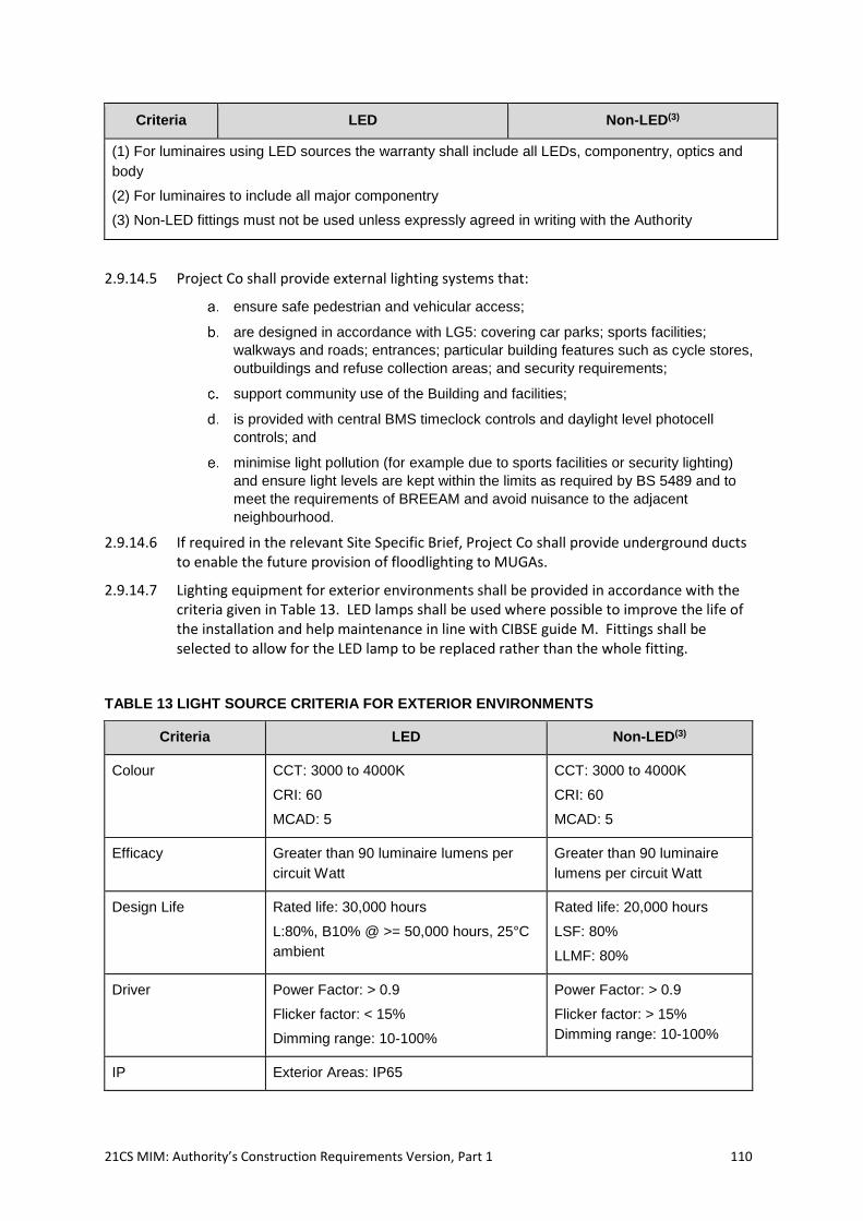
21CS MIM: Authority’s Construction Requirements Version, Part 1 110
Criteria LED Non-LED(3)
(1) For luminaires using LED sources the warranty shall include all LEDs, componentry, optics and
body
(2) For luminaires to include all major componentry
(3) Non-LED fittings must not be used unless expressly agreed in writing with the Authority
2.9.14.5 Project Co shall provide external lighting systems that:
ensure safe pedestrian and vehicular access;
are designed in accordance with LG5: covering car parks; sports facilities;
walkways and roads; entrances; particular building features such as cycle stores,
outbuildings and refuse collection areas; and security requirements;
support community use of the Building and facilities;
is provided with central BMS timeclock controls and daylight level photocell
controls; and
minimise light pollution (for example due to sports facilities or security lighting)
and ensure light levels are kept within the limits as required by BS 5489 and to
meet the requirements of BREEAM and avoid nuisance to the adjacent
neighbourhood.
2.9.14.6 If required in the relevant Site Specific Brief, Project Co shall provide underground ducts to enable the future provision of floodlighting to MUGAs.
2.9.14.7 Lighting equipment for exterior environments shall be provided in accordance with the criteria given in Table 13. LED lamps shall be used where possible to improve the life of the installation and help maintenance in line with CIBSE guide M. Fittings shall be selected to allow for the LED lamp to be replaced rather than the whole fitting.
TABLE 13 LIGHT SOURCE CRITERIA FOR EXTERIOR ENVIRONMENTS
Criteria LED Non-LED(3)
Colour CCT: 3000 to 4000K
CRI: 60
MCAD: 5
CCT: 3000 to 4000K
CRI: 60
MCAD: 5
Efficacy Greater than 90 luminaire lumens per
circuit Watt
Greater than 90 luminaire
lumens per circuit Watt
Design Life Rated life: 30,000 hours
L:80%, B10% @ >= 50,000 hours, 25°C
ambient
Rated life: 20,000 hours
LSF: 80%
LLMF: 80%
Driver Power Factor: > 0.9
Flicker factor: < 15%
Dimming range: 10-100%
Power Factor: > 0.9
Flicker factor: > 15%
Dimming range: 10-100%
IP Exterior Areas: IP65
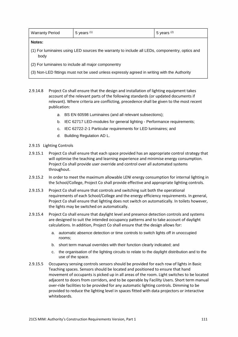
21CS MIM: Authority’s Construction Requirements Version, Part 1 111
Warranty Period 5 years (1) 5 years (2)
Notes:
(1) For luminaires using LED sources the warranty to include all LEDs, componentry, optics and
body
(2) For luminaires to include all major componentry
(3) Non-LED fittings must not be used unless expressly agreed in writing with the Authority
2.9.14.8 Project Co shall ensure that the design and installation of lighting equipment takes account of the relevant parts of the following standards (or updated documents if relevant). Where criteria are conflicting, precedence shall be given to the most recent publication:
BS EN 60598 Luminaires (and all relevant subsections);
IEC 62717 LED-modules for general lighting - Performance requirements;
IEC 62722-2-1 Particular requirements for LED luminaires; and
Building Regulation AD L.
2.9.15 Lighting Controls
2.9.15.1 Project Co shall ensure that each space provided has an appropriate control strategy that will optimise the teaching and learning experience and minimise energy consumption. Project Co shall provide user override and control over all automated systems throughout.
2.9.15.2 In order to meet the maximum allowable LENI energy consumption for internal lighting in the School/College, Project Co shall provide effective and appropriate lighting controls.
2.9.15.3 Project Co shall ensure that controls and switching suit both the operational requirements of each School/College and the energy efficiency requirements. In general, Project Co shall ensure that lighting does not switch on automatically. In toilets however, the lights may be switched on automatically.
2.9.15.4 Project Co shall ensure that daylight level and presence detection controls and systems are designed to suit the intended occupancy patterns and to take account of daylight calculations. In addition, Project Co shall ensure that the design allows for:
a. automatic absence detection or time controls to switch lights off in unoccupied
rooms;
b. short term manual overrides with their function clearly indicated; and
c. the organisation of the lighting circuits to relate to the daylight distribution and to the
use of the space.
2.9.15.5 Occupancy sensing controls sensors should be provided for each row of lights in Basic Teaching spaces. Sensors should be located and positioned to ensure that hand movement of occupants is picked up in all areas of the room. Light switches to be located adjacent to doors from corridors, and to be operable by Facility Users. Short term manual over-ride facilities to be provided for any automatic lighting controls. Dimming to be provided to reduce the lighting level in spaces fitted with data projectors or interactive whiteboards.
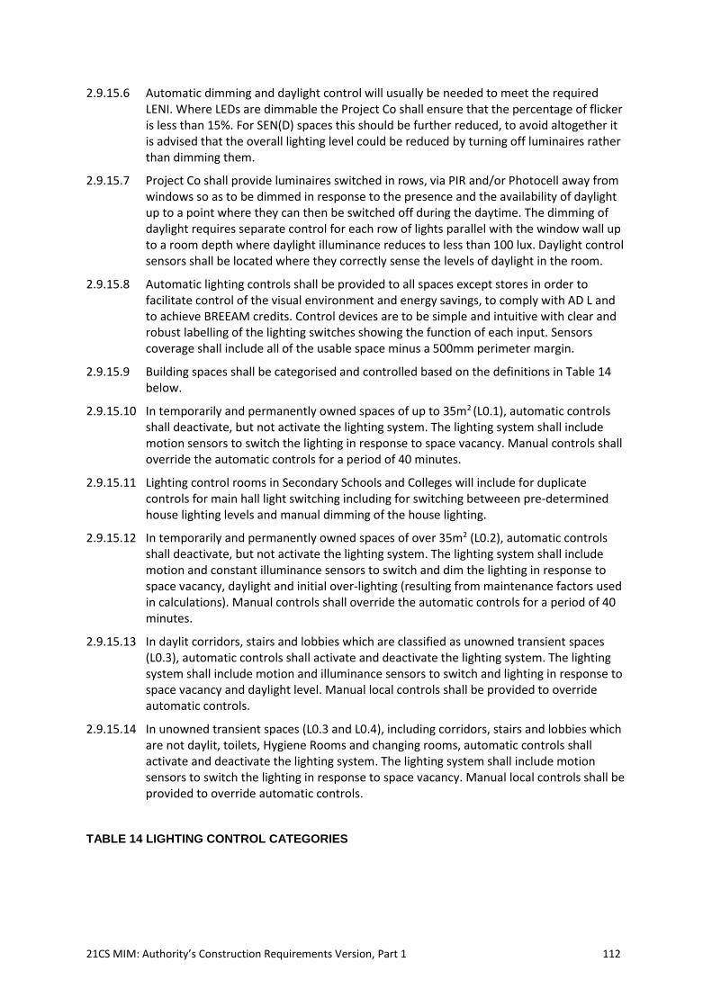
21CS MIM: Authority’s Construction Requirements Version, Part 1 112
2.9.15.6 Automatic dimming and daylight control will usually be needed to meet the required LENI. Where LEDs are dimmable the Project Co shall ensure that the percentage of flicker is less than 15%. For SEN(D) spaces this should be further reduced, to avoid altogether it is advised that the overall lighting level could be reduced by turning off luminaires rather than dimming them.
2.9.15.7 Project Co shall provide luminaires switched in rows, via PIR and/or Photocell away from windows so as to be dimmed in response to the presence and the availability of daylight up to a point where they can then be switched off during the daytime. The dimming of daylight requires separate control for each row of lights parallel with the window wall up to a room depth where daylight illuminance reduces to less than 100 lux. Daylight control sensors shall be located where they correctly sense the levels of daylight in the room.
2.9.15.8 Automatic lighting controls shall be provided to all spaces except stores in order to facilitate control of the visual environment and energy savings, to comply with AD L and to achieve BREEAM credits. Control devices are to be simple and intuitive with clear and robust labelling of the lighting switches showing the function of each input. Sensors coverage shall include all of the usable space minus a 500mm perimeter margin.
2.9.15.9 Building spaces shall be categorised and controlled based on the definitions in Table 14 below.
2.9.15.10 In temporarily and permanently owned spaces of up to 35m2 (L0.1), automatic controls shall deactivate, but not activate the lighting system. The lighting system shall include motion sensors to switch the lighting in response to space vacancy. Manual controls shall override the automatic controls for a period of 40 minutes.
2.9.15.11 Lighting control rooms in Secondary Schools and Colleges will include for duplicate controls for main hall light switching including for switching betweeen pre-determined house lighting levels and manual dimming of the house lighting.
2.9.15.12 In temporarily and permanently owned spaces of over 35m2 (L0.2), automatic controls shall deactivate, but not activate the lighting system. The lighting system shall include motion and constant illuminance sensors to switch and dim the lighting in response to space vacancy, daylight and initial over-lighting (resulting from maintenance factors used in calculations). Manual controls shall override the automatic controls for a period of 40 minutes.
2.9.15.13 In daylit corridors, stairs and lobbies which are classified as unowned transient spaces (L0.3), automatic controls shall activate and deactivate the lighting system. The lighting system shall include motion and illuminance sensors to switch and lighting in response to space vacancy and daylight level. Manual local controls shall be provided to override automatic controls.
2.9.15.14 In unowned transient spaces (L0.3 and L0.4), including corridors, stairs and lobbies which are not daylit, toilets, Hygiene Rooms and changing rooms, automatic controls shall activate and deactivate the lighting system. The lighting system shall include motion sensors to switch the lighting in response to space vacancy. Manual local controls shall be provided to override automatic controls.
TABLE 14 LIGHTING CONTROL CATEGORIES
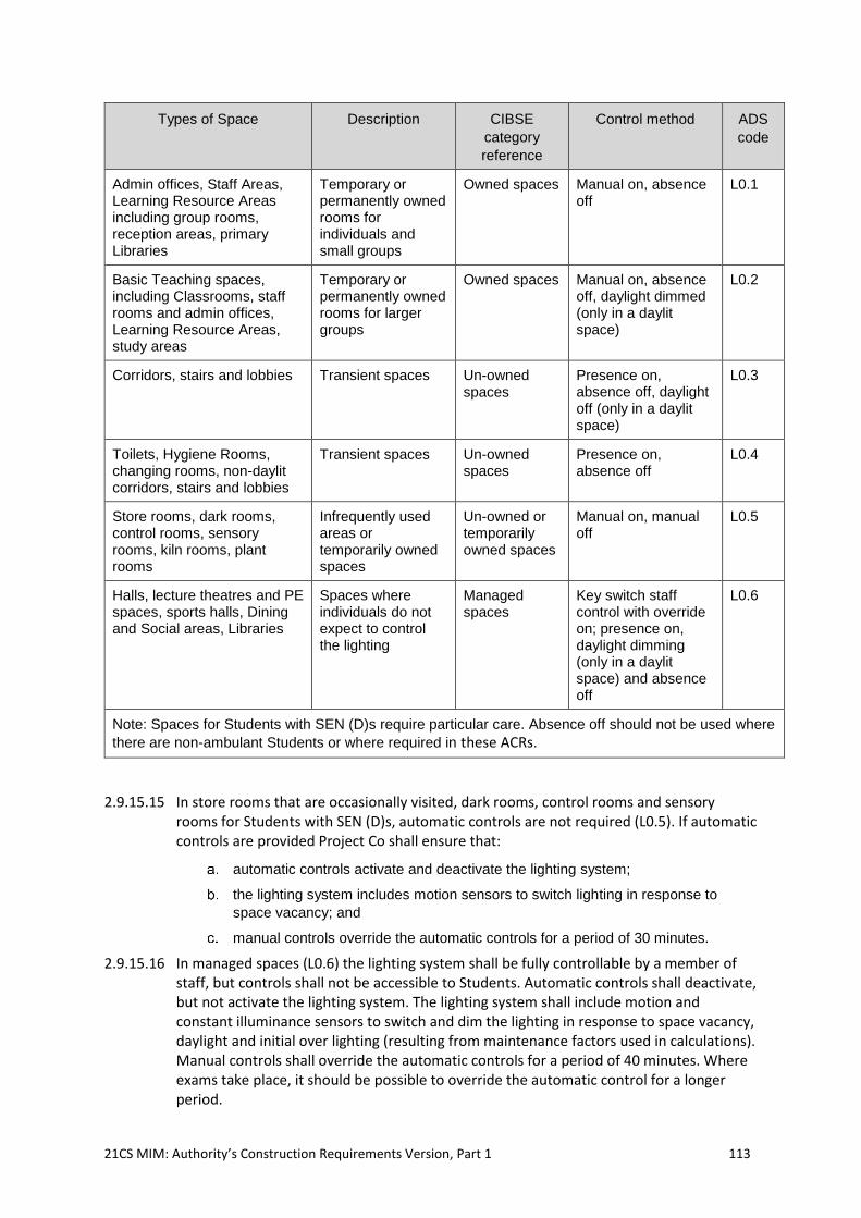
21CS MIM: Authority’s Construction Requirements Version, Part 1 113
Types of Space Description CIBSE
category
reference
Control method ADS
code
Admin offices, Staff Areas, Learning Resource Areas including group rooms, reception areas, primary Libraries
Temporary or permanently owned rooms for individuals and small groups
Owned spaces Manual on, absence off
L0.1
Basic Teaching spaces, including Classrooms, staff rooms and admin offices, Learning Resource Areas, study areas
Temporary or permanently owned rooms for larger groups
Owned spaces Manual on, absence off, daylight dimmed (only in a daylit space)
L0.2
Corridors, stairs and lobbies Transient spaces Un-owned spaces
Presence on, absence off, daylight off (only in a daylit space)
L0.3
Toilets, Hygiene Rooms, changing rooms, non-daylit corridors, stairs and lobbies
Transient spaces Un-owned spaces
Presence on, absence off
L0.4
Store rooms, dark rooms, control rooms, sensory rooms, kiln rooms, plant rooms
Infrequently used areas or temporarily owned spaces
Un-owned or temporarily owned spaces
Manual on, manual off
L0.5
Halls, lecture theatres and PE spaces, sports halls, Dining and Social areas, Libraries
Spaces where individuals do not expect to control the lighting
Managed spaces
Key switch staff control with override on; presence on, daylight dimming (only in a daylit space) and absence off
L0.6
Note: Spaces for Students with SEN (D)s require particular care. Absence off should not be used where
there are non-ambulant Students or where required in these ACRs.
2.9.15.15 In store rooms that are occasionally visited, dark rooms, control rooms and sensory rooms for Students with SEN (D)s, automatic controls are not required (L0.5). If automatic controls are provided Project Co shall ensure that:
automatic controls activate and deactivate the lighting system;
the lighting system includes motion sensors to switch lighting in response to
space vacancy; and
manual controls override the automatic controls for a period of 30 minutes.
2.9.15.16 In managed spaces (L0.6) the lighting system shall be fully controllable by a member of staff, but controls shall not be accessible to Students. Automatic controls shall deactivate, but not activate the lighting system. The lighting system shall include motion and constant illuminance sensors to switch and dim the lighting in response to space vacancy, daylight and initial over lighting (resulting from maintenance factors used in calculations). Manual controls shall override the automatic controls for a period of 40 minutes. Where exams take place, it should be possible to override the automatic control for a longer period.
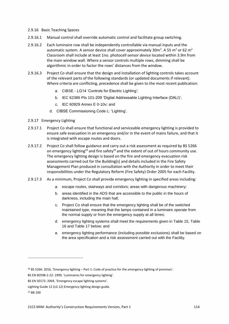
21CS MIM: Authority’s Construction Requirements Version, Part 1 114
2.9.16 Basic Teaching Spaces
2.9.16.1 Manual control shall override automatic control and facilitate group switching.
2.9.16.2 Each luminaire row shall be independently controllable via manual inputs and the automatic system. A sensor device shall cover approximately 30m2. A 55 m2 or 62 m2 Classroom shall include at least 1no. photocell sensor device located within 3.9m from the main window wall. Where a sensor controls multiple rows, dimming shall be algorithmic in order to factor the rows’ distances from the window.
2.9.16.3 Project Co shall ensure that the design and installation of lighting controls takes account of the relevant parts of the following standards (or updated documents if relevant). Where criteria are conflicting, precedence shall be given to the most recent publication:
CIBSE - LG14 ‘Controls for Electric Lighting’;
IEC 62386 Pts 101-209 ‘Digital Addressable Lighting Interface (DALI)’;
IEC 60929 Annex E 0-10v; and
d. CIBSE Commissioning Code L: ‘Lighting’.
2.9.17 Emergency Lighting
2.9.17.1 Project Co shall ensure that functional and serviceable emergency lighting is provided to ensure safe evacuation in an emergency and/or in the event of mains failure, and that it is integrated with escape routes and doors.
2.9.17.2 Project Co shall follow guidance and carry out a risk assessment as required by BS 5266 on emergency lighting24 and fire safety25 and the extent of out of hours community use. The emergency lighting design is based on the fire and emergency evacuation risk assessments carried out for the Building[s] and details included in the Fire Safety Management Plan produced in consultation with the Authority in order to meet their responsibilities under the Regulatory Reform (Fire Safety) Order 2005 for each Facility.
2.9.17.3 As a minimum, Project Co shall provide emergency lighting in specified areas including:
escape routes, stairways and corridors; areas with dangerous machinery;
areas identified in the ADS that are accessible to the public in the hours of
darkness, including the main hall;
Project Co shall ensure that the emergency lighting shall be of the switched
maintained type, meaning that the lamps contained in a luminaire operate from
the normal supply or from the emergency supply at all times;
emergency lighting systems shall meet the requirements given in Table 15, Table
16 and Table 17 below; and
emergency lighting performance (including possible exclusions) shall be based on
the area specification and a risk assessment carried out with the Facility.
24 BS 5266: 2016, ‘Emergency lighting – Part 1: Code of practice for the emergency lighting of premises’.
BS EN 60598-2-22: 1999, ‘Luminaires for emergency lighting’.
BS EN 50172: 2004, ‘Emergency escape lighting systems’.
Lighting Guide 12 (LG 12) Emergency lighting design guide.
25 BB 100
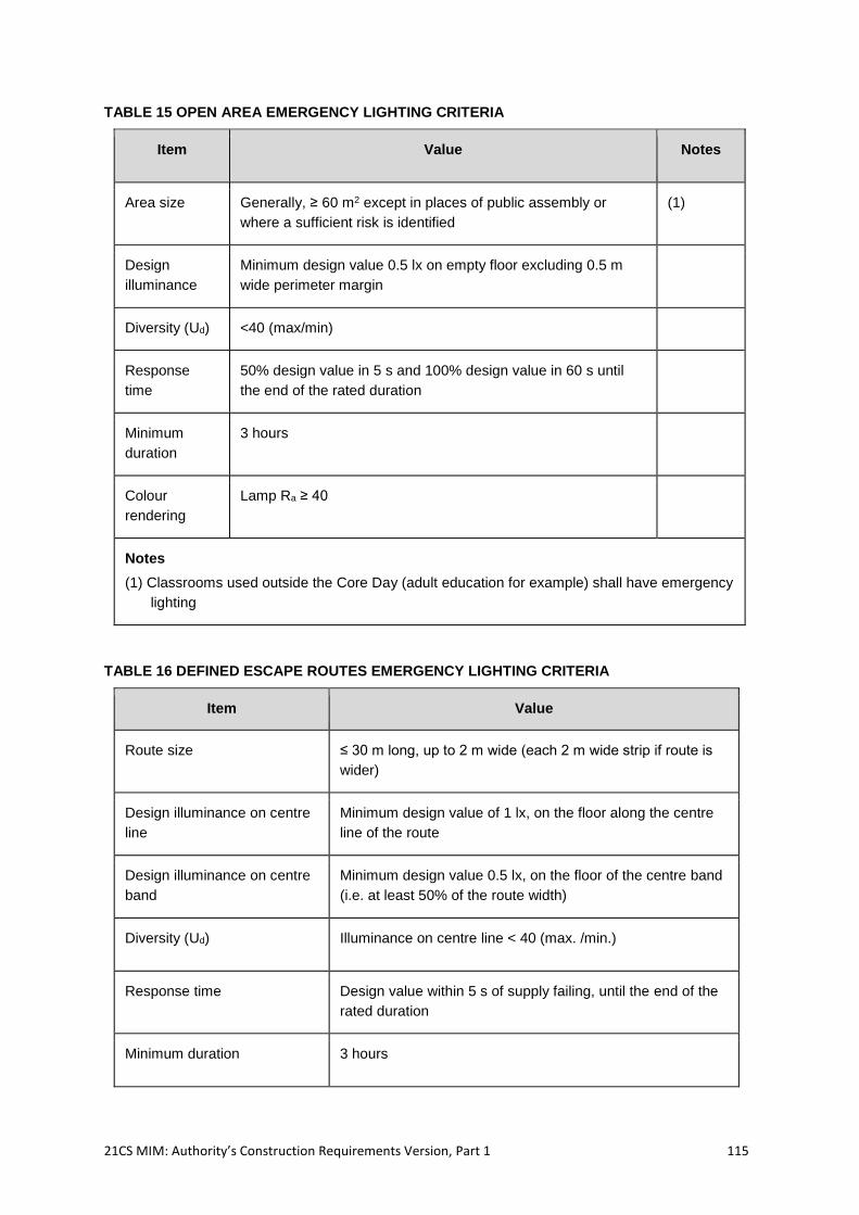
21CS MIM: Authority’s Construction Requirements Version, Part 1 115
TABLE 15 OPEN AREA EMERGENCY LIGHTING CRITERIA
Item Value Notes
Area size Generally, ≥ 60 m2 except in places of public assembly or
where a sufficient risk is identified
(1)
Design
illuminance
Minimum design value 0.5 lx on empty floor excluding 0.5 m
wide perimeter margin
Diversity (Ud) <40 (max/min)
Response
time
50% design value in 5 s and 100% design value in 60 s until
the end of the rated duration
Minimum
duration
3 hours
Colour
rendering
Lamp Ra ≥ 40
Notes
(1) Classrooms used outside the Core Day (adult education for example) shall have emergency
lighting
TABLE 16 DEFINED ESCAPE ROUTES EMERGENCY LIGHTING CRITERIA
Item Value
Route size ≤ 30 m long, up to 2 m wide (each 2 m wide strip if route is
wider)
Design illuminance on centre
line
Minimum design value of 1 lx, on the floor along the centre
line of the route
Design illuminance on centre
band
Minimum design value 0.5 lx, on the floor of the centre band
(i.e. at least 50% of the route width)
Diversity (Ud) Illuminance on centre line < 40 (max. /min.)
Response time Design value within 5 s of supply failing, until the end of the
rated duration
Minimum duration 3 hours
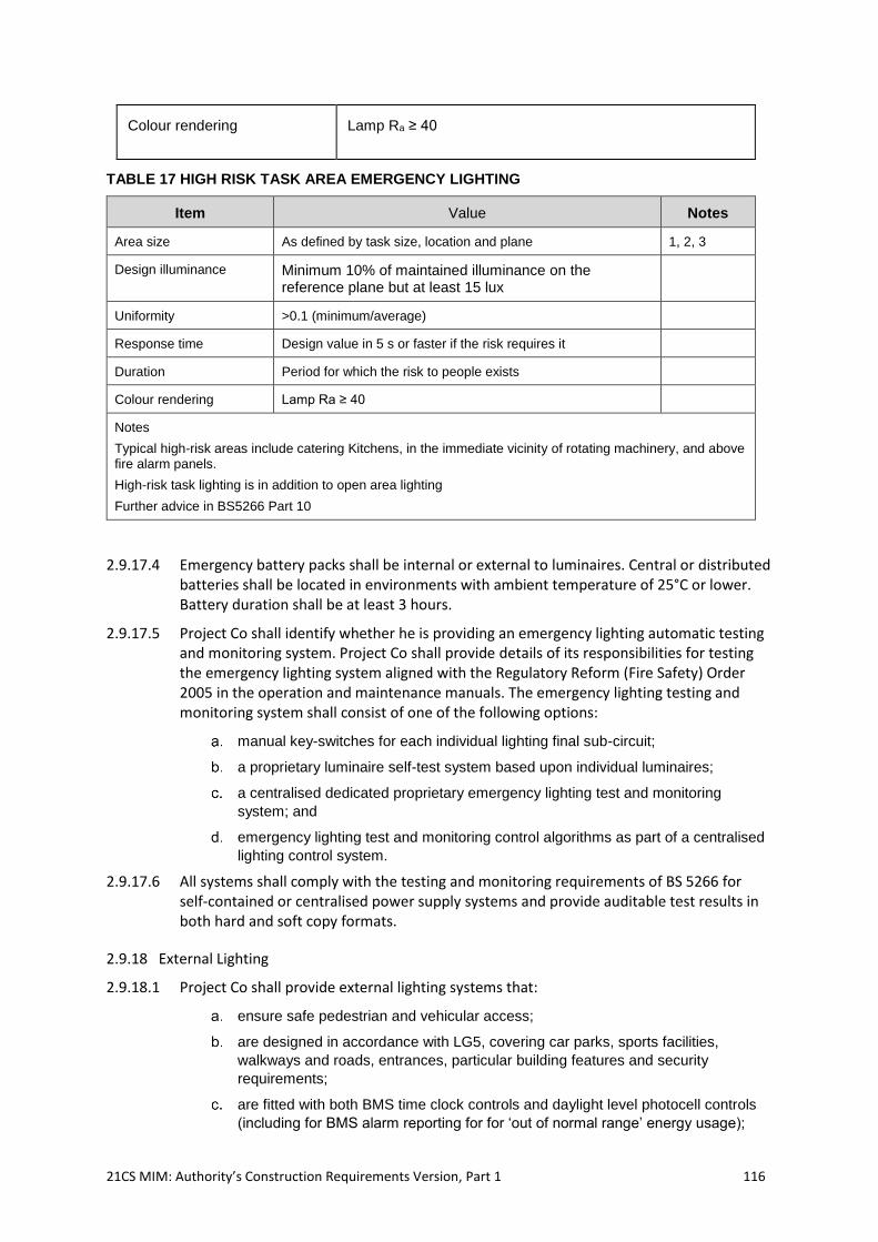
21CS MIM: Authority’s Construction Requirements Version, Part 1 116
Colour rendering Lamp Ra ≥ 40
TABLE 17 HIGH RISK TASK AREA EMERGENCY LIGHTING
Item Value Notes
Area size As defined by task size, location and plane 1, 2, 3
Design illuminance Minimum 10% of maintained illuminance on the reference plane but at least 15 lux
Uniformity >0.1 (minimum/average)
Response time Design value in 5 s or faster if the risk requires it
Duration Period for which the risk to people exists
Colour rendering Lamp Ra ≥ 40
Notes
Typical high-risk areas include catering Kitchens, in the immediate vicinity of rotating machinery, and above fire alarm panels.
High-risk task lighting is in addition to open area lighting
Further advice in BS5266 Part 10
2.9.17.4 Emergency battery packs shall be internal or external to luminaires. Central or distributed batteries shall be located in environments with ambient temperature of 25°C or lower. Battery duration shall be at least 3 hours.
2.9.17.5 Project Co shall identify whether he is providing an emergency lighting automatic testing and monitoring system. Project Co shall provide details of its responsibilities for testing the emergency lighting system aligned with the Regulatory Reform (Fire Safety) Order 2005 in the operation and maintenance manuals. The emergency lighting testing and monitoring system shall consist of one of the following options:
manual key-switches for each individual lighting final sub-circuit;
a proprietary luminaire self-test system based upon individual luminaires;
a centralised dedicated proprietary emergency lighting test and monitoring
system; and
emergency lighting test and monitoring control algorithms as part of a centralised
lighting control system.
2.9.17.6 All systems shall comply with the testing and monitoring requirements of BS 5266 for self-contained or centralised power supply systems and provide auditable test results in both hard and soft copy formats.
2.9.18 External Lighting
2.9.18.1 Project Co shall provide external lighting systems that:
ensure safe pedestrian and vehicular access;
are designed in accordance with LG5, covering car parks, sports facilities,
walkways and roads, entrances, particular building features and security
requirements;
are fitted with both BMS time clock controls and daylight level photocell controls
(including for BMS alarm reporting for for ‘out of normal range’ energy usage);
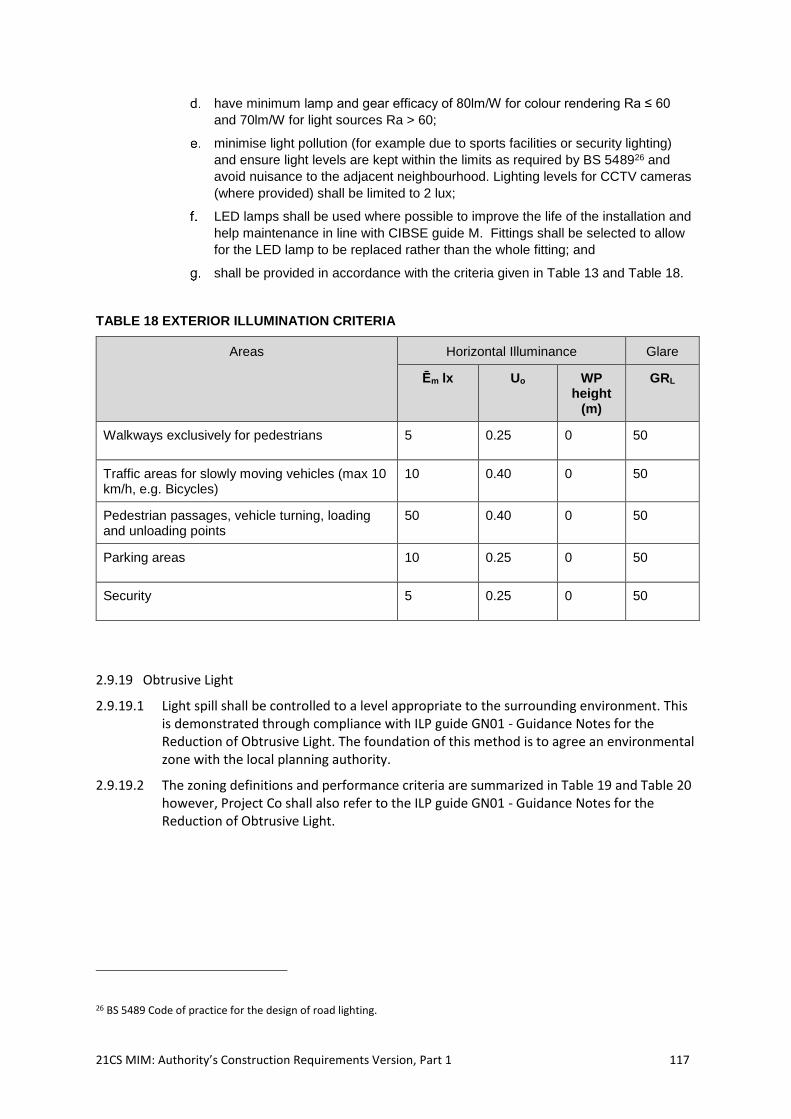
21CS MIM: Authority’s Construction Requirements Version, Part 1 117
have minimum lamp and gear efficacy of 80lm/W for colour rendering Ra ≤ 60
and 70lm/W for light sources Ra > 60;
minimise light pollution (for example due to sports facilities or security lighting)
and ensure light levels are kept within the limits as required by BS 548926 and
avoid nuisance to the adjacent neighbourhood. Lighting levels for CCTV cameras
(where provided) shall be limited to 2 lux;
LED lamps shall be used where possible to improve the life of the installation and
help maintenance in line with CIBSE guide M. Fittings shall be selected to allow
for the LED lamp to be replaced rather than the whole fitting; and
shall be provided in accordance with the criteria given in Table 13 and Table 18.
TABLE 18 EXTERIOR ILLUMINATION CRITERIA
Areas Horizontal Illuminance Glare
Ēm lx Uo WP height
(m)
GRL
Walkways exclusively for pedestrians 5 0.25 0 50
Traffic areas for slowly moving vehicles (max 10 km/h, e.g. Bicycles)
10 0.40 0 50
Pedestrian passages, vehicle turning, loading and unloading points
50 0.40 0 50
Parking areas 10 0.25 0 50
Security 5 0.25 0 50
2.9.19 Obtrusive Light
2.9.19.1 Light spill shall be controlled to a level appropriate to the surrounding environment. This is demonstrated through compliance with ILP guide GN01 - Guidance Notes for the Reduction of Obtrusive Light. The foundation of this method is to agree an environmental zone with the local planning authority.
2.9.19.2 The zoning definitions and performance criteria are summarized in Table 19 and Table 20 however, Project Co shall also refer to the ILP guide GN01 - Guidance Notes for the Reduction of Obtrusive Light.
26 BS 5489 Code of practice for the design of road lighting.
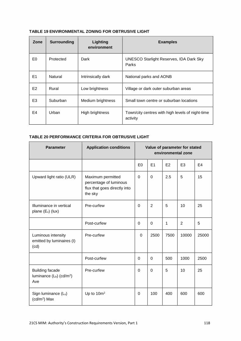
21CS MIM: Authority’s Construction Requirements Version, Part 1 118
TABLE 19 ENVIRONMENTAL ZONING FOR OBTRUSIVE LIGHT
Zone Surrounding Lighting
environment
Examples
E0 Protected Dark UNESCO Starlight Reserves, IDA Dark Sky
Parks
E1 Natural Intrinsically dark National parks and AONB
E2 Rural Low brightness Village or dark outer suburban areas
E3 Suburban Medium brightness Small town centre or suburban locations
E4 Urban High brightness Town/city centres with high levels of night-time
activity
TABLE 20 PERFORMANCE CRITERIA FOR OBTRUSIVE LIGHT
Parameter Application conditions Value of parameter for stated
environmental zone
E0 E1 E2 E3 E4
Upward light ratio (ULR) Maximum permitted
percentage of luminous
flux that goes directly into
the sky
0 0 2.5 5 15
Illuminance in vertical
plane (Ev) (lux)
Pre-curfew 0 2 5 10 25
Post-curfew 0 0 1 2 5
Luminous intensity
emitted by luminaires (I)
(cd)
Pre-curfew 0 2500 7500 10000 25000
Post-curfew 0 0 500 1000 2500
Building facade
luminance (Lb) (cd/m2)
Ave
Pre-curfew 0 0 5 10 25
Sign luminance (Ls)
(cd/m2) Max
Up to 10m2 0 100 400 600 600
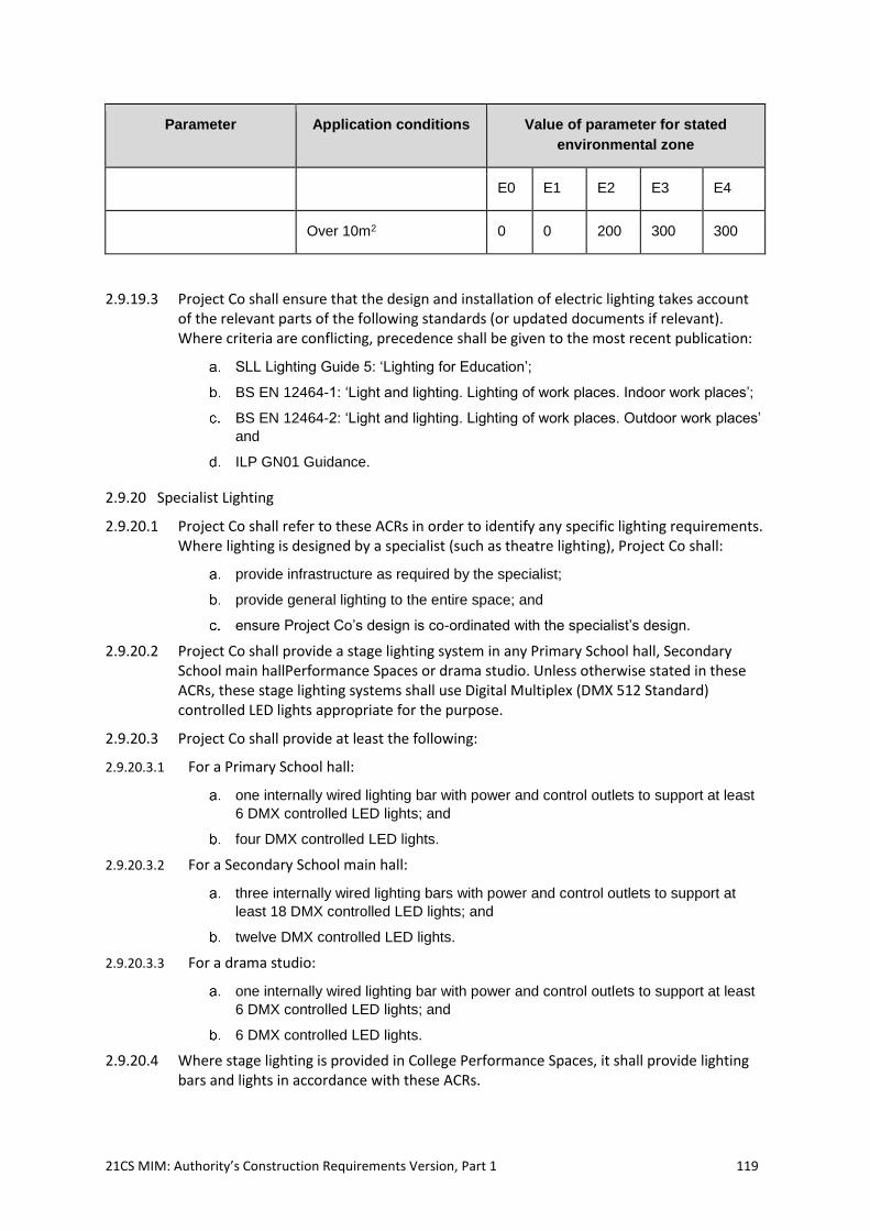
21CS MIM: Authority’s Construction Requirements Version, Part 1 119
Parameter Application conditions Value of parameter for stated
environmental zone
E0 E1 E2 E3 E4
Over 10m2 0 0 200 300 300
2.9.19.3 Project Co shall ensure that the design and installation of electric lighting takes account of the relevant parts of the following standards (or updated documents if relevant). Where criteria are conflicting, precedence shall be given to the most recent publication:
SLL Lighting Guide 5: ‘Lighting for Education’;
BS EN 12464-1: ‘Light and lighting. Lighting of work places. Indoor work places’;
BS EN 12464-2: ‘Light and lighting. Lighting of work places. Outdoor work places’
and
ILP GN01 Guidance.
2.9.20 Specialist Lighting
2.9.20.1 Project Co shall refer to these ACRs in order to identify any specific lighting requirements. Where lighting is designed by a specialist (such as theatre lighting), Project Co shall:
provide infrastructure as required by the specialist;
provide general lighting to the entire space; and
ensure Project Co’s design is co-ordinated with the specialist’s design.
2.9.20.2 Project Co shall provide a stage lighting system in any Primary School hall, Secondary School main hallPerformance Spaces or drama studio. Unless otherwise stated in these ACRs, these stage lighting systems shall use Digital Multiplex (DMX 512 Standard) controlled LED lights appropriate for the purpose.
2.9.20.3 Project Co shall provide at least the following:
2.9.20.3.1 For a Primary School hall:
one internally wired lighting bar with power and control outlets to support at least
6 DMX controlled LED lights; and
four DMX controlled LED lights.
2.9.20.3.2 For a Secondary School main hall:
three internally wired lighting bars with power and control outlets to support at
least 18 DMX controlled LED lights; and
twelve DMX controlled LED lights.
2.9.20.3.3 For a drama studio:
one internally wired lighting bar with power and control outlets to support at least
6 DMX controlled LED lights; and
6 DMX controlled LED lights.
2.9.20.4 Where stage lighting is provided in College Performance Spaces, it shall provide lighting bars and lights in accordance with these ACRs.
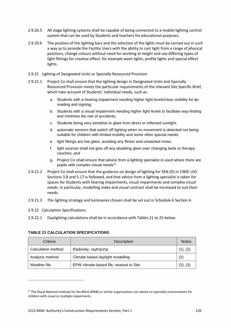
21CS MIM: Authority’s Construction Requirements Version, Part 1 120
2.9.20.5 All stage lighting systems shall be capable of being connected to a mobile lighting control system that can be used by Students and teachers for educational purposes.
2.9.20.6 The position of the lighting bars and the selection of the lights must be carried out in such a way as to provide the Facility Users with the ability to cast light from a range of physical positions, change colours without need for working at height and use differing types of light fittings for creative effect, for example wash lights, profile lights and special effect lights.
2.9.21 Lighting of Designated Units or Specially Resourced Provision
2.9.21.1 Project Co shall ensure that the lighting design in Designated Units and Specially Resourced Provision meets the particular requirements of the relevant Site Specific Brief, which take account of Students’ individual needs, such as:
a. Students with a hearing impairment needing higher light levels/clear visibility for lip-
reading and signing;
b. Students with a visual impairment needing higher light levels to facilitate way-finding
and minimise the risk of accidents;
c. Students being very sensitive to glare from direct or reflected sunlight;
d. automatic sensors that switch off lighting when no movement is detected not being
suitable for children with limited mobility and some other special needs;
e. light fittings are low glare, avoiding any flicker and unwanted noise;
f. light sources shall not give off any disabling glare over changing beds or therapy
couches; and
g. Project Co shall ensure that advice from a lighting specialist is used where there are
pupils with complex visual needs27.
2.9.21.2 Project Co shall ensure that the guidance on design of lighting for SEN (D) in CIBSE LG5 Sections 3.8 and 5.17 is followed, and that advice from a lighting specialist is taken for spaces for Students with hearing impairments, visual impairments and complex visual needs. In particular, modelling index and visual contract shall be increased to suit their needs.
2.9.21.3 The lighting strategy and luminaires chosen shall be set out in Schedule 6 Section 4.
2.9.22 Calculation Specifications
2.9.22.1 Daylighting calculations shall be in accordance with Tables 21 to 25 below.
TABLE 21 CALCULATION SPECIFICATIONS
Criteria Description Notes
Calculation method Radiosity, raytracing (1), (2)
Analysis method Climate based daylight modelling (2)
Weather file EPW climate-based file, nearest to Site (2), (3)
27 The Royal National Institute for the Blind (RNIB) or similar organisations can advise on specialist environments for children with visual or multiple impairments.
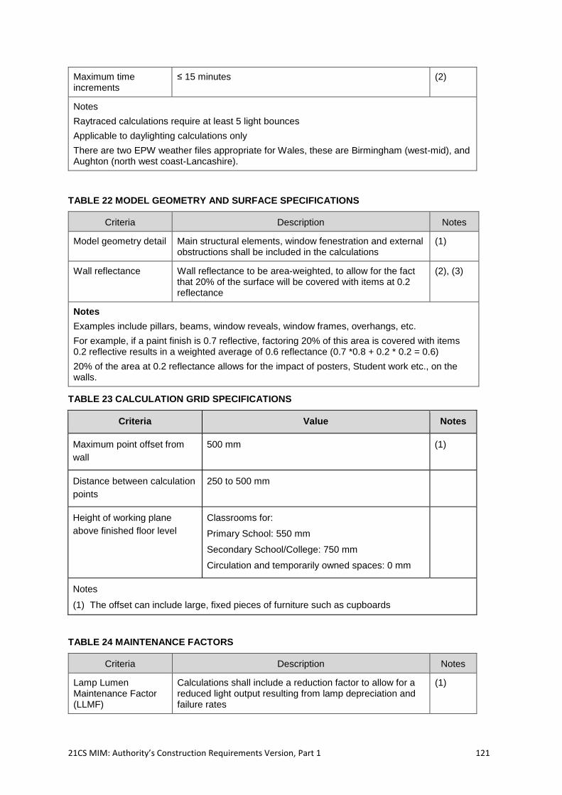
21CS MIM: Authority’s Construction Requirements Version, Part 1 121
Maximum time increments
≤ 15 minutes (2)
Notes
Raytraced calculations require at least 5 light bounces
Applicable to daylighting calculations only
There are two EPW weather files appropriate for Wales, these are Birmingham (west-mid), and Aughton (north west coast-Lancashire).
TABLE 22 MODEL GEOMETRY AND SURFACE SPECIFICATIONS
Criteria Description Notes
Model geometry detail Main structural elements, window fenestration and external obstructions shall be included in the calculations
(1)
Wall reflectance Wall reflectance to be area-weighted, to allow for the fact that 20% of the surface will be covered with items at 0.2 reflectance
(2), (3)
Notes
Examples include pillars, beams, window reveals, window frames, overhangs, etc.
For example, if a paint finish is 0.7 reflective, factoring 20% of this area is covered with items 0.2 reflective results in a weighted average of 0.6 reflectance (0.7 *0.8 + 0.2 * 0.2 = 0.6)
20% of the area at 0.2 reflectance allows for the impact of posters, Student work etc., on the walls.
TABLE 23 CALCULATION GRID SPECIFICATIONS
Criteria Value Notes
Maximum point offset from
wall
500 mm (1)
Distance between calculation
points
250 to 500 mm
Height of working plane
above finished floor level
Classrooms for:
Primary School: 550 mm
Secondary School/College: 750 mm
Circulation and temporarily owned spaces: 0 mm
Notes
(1) The offset can include large, fixed pieces of furniture such as cupboards
TABLE 24 MAINTENANCE FACTORS
Criteria Description Notes
Lamp Lumen Maintenance Factor (LLMF)
Calculations shall include a reduction factor to allow for a reduced light output resulting from lamp depreciation and failure rates
(1)
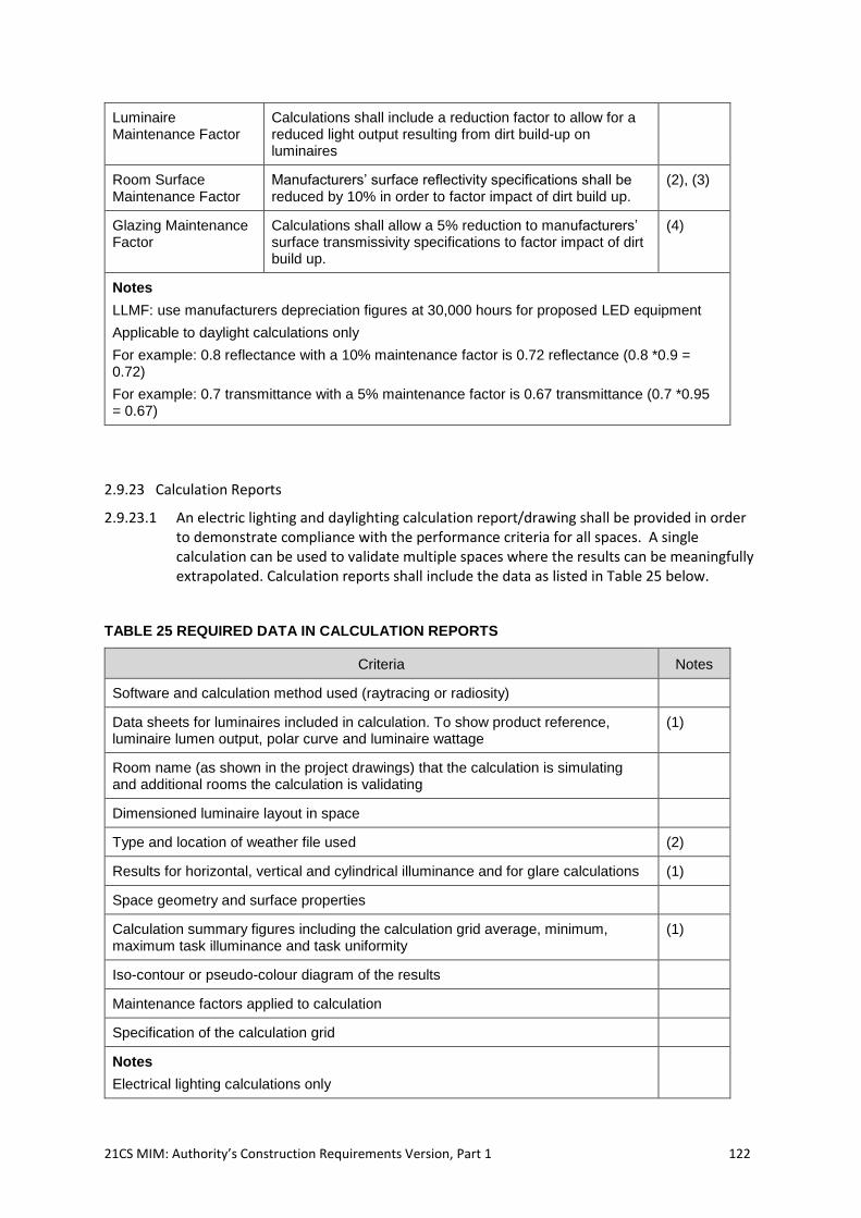
21CS MIM: Authority’s Construction Requirements Version, Part 1 122
Luminaire Maintenance Factor
Calculations shall include a reduction factor to allow for a reduced light output resulting from dirt build-up on luminaires
Room Surface Maintenance Factor
Manufacturers’ surface reflectivity specifications shall be reduced by 10% in order to factor impact of dirt build up.
(2), (3)
Glazing Maintenance Factor
Calculations shall allow a 5% reduction to manufacturers’ surface transmissivity specifications to factor impact of dirt build up.
(4)
Notes
LLMF: use manufacturers depreciation figures at 30,000 hours for proposed LED equipment
Applicable to daylight calculations only
For example: 0.8 reflectance with a 10% maintenance factor is 0.72 reflectance (0.8 *0.9 = 0.72)
For example: 0.7 transmittance with a 5% maintenance factor is 0.67 transmittance (0.7 *0.95 = 0.67)
2.9.23 Calculation Reports
2.9.23.1 An electric lighting and daylighting calculation report/drawing shall be provided in order to demonstrate compliance with the performance criteria for all spaces. A single calculation can be used to validate multiple spaces where the results can be meaningfully extrapolated. Calculation reports shall include the data as listed in Table 25 below.
TABLE 25 REQUIRED DATA IN CALCULATION REPORTS
Criteria Notes
Software and calculation method used (raytracing or radiosity)
Data sheets for luminaires included in calculation. To show product reference, luminaire lumen output, polar curve and luminaire wattage
(1)
Room name (as shown in the project drawings) that the calculation is simulating and additional rooms the calculation is validating
Dimensioned luminaire layout in space
Type and location of weather file used (2)
Results for horizontal, vertical and cylindrical illuminance and for glare calculations (1)
Space geometry and surface properties
Calculation summary figures including the calculation grid average, minimum, maximum task illuminance and task uniformity
(1)
Iso-contour or pseudo-colour diagram of the results
Maintenance factors applied to calculation
Specification of the calculation grid
Notes
Electrical lighting calculations only
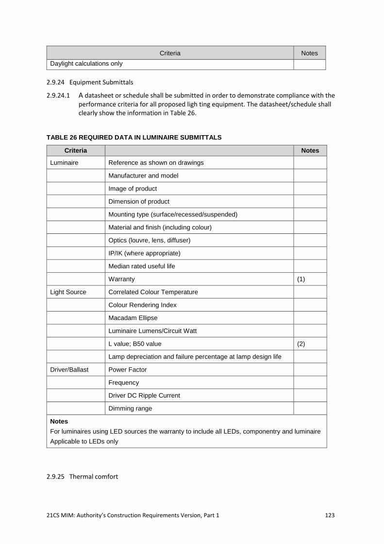
21CS MIM: Authority’s Construction Requirements Version, Part 1 123
Criteria Notes
Daylight calculations only
2.9.24 Equipment Submittals
2.9.24.1 A datasheet or schedule shall be submitted in order to demonstrate compliance with the performance criteria for all proposed ligh ting equipment. The datasheet/schedule shall clearly show the information in Table 26.
TABLE 26 REQUIRED DATA IN LUMINAIRE SUBMITTALS
Criteria Notes
Luminaire Reference as shown on drawings
Manufacturer and model
Image of product
Dimension of product
Mounting type (surface/recessed/suspended)
Material and finish (including colour)
Optics (louvre, lens, diffuser)
IP/IK (where appropriate)
Median rated useful life
Warranty (1)
Light Source Correlated Colour Temperature
Colour Rendering Index
Macadam Ellipse
Luminaire Lumens/Circuit Watt
L value; B50 value (2)
Lamp depreciation and failure percentage at lamp design life
Driver/Ballast Power Factor
Frequency
Driver DC Ripple Current
Dimming range
Notes
For luminaires using LED sources the warranty to include all LEDs, componentry and luminaire
Applicable to LEDs only
2.9.25 Thermal comfort
21CS MIM: Authority’s Construction Requirements Version, Part 1 124
2.9.25.1 Project Co shall ensure that all spaces provided are designed to meet the requirements for design criteria for thermal comfort.
2.9.25.2 All parts of new and refurbished Buildings shall comply with the temperature requirements set out in these ACRs.
2.9.25.3 For summertime thermal comfort, Project Co shall carry out an Overheating Risk Assessment (ORA) of free running designs and shall design and install all heating systems so as to limit the maximum internal temperatures.
2.9.25.4 For wintertime thermal comfort, Project Co shall design all heating systems so as to ensure that the minimum temperatures are in line with the design conditions set out in these ACRs.
2.9.25.5 Project Co shall ensure that systems provided to control thermal comfort for Students with SEN (D)s are designed such that:
they take into account any specialist requirements of the Students described in
these ACRs;
they do not have a detrimental effect on the learning environment of the Students;
and
they provide a safe and secure environment for the occupants.
2.9.25.6 Project Co shall demonstrate by thermal modelling how all parts of the Buildings will comply with the minimum and maximum temperature requirements as shown in the ADS.
2.9.25.7 Project Co shall ensure that there are sufficient temperature control mechanisms provided to enable the staff and Students to adjust their environment and maintain a satisfactory level of thermal comfort throughout each term. This is especially important in spaces subject to high heat gains.
2.9.25.8 In naturally ventilated spaces, Project Co shall provide mixing of ventilation air with room air to avoid cold draughts in the occupied zone during wintertime. In wintertime the minimum air temperature of air delivered to the occupied zone at 1.4m above floor level shall be not more than 5°C below the normal maintained air temperature. Further detailed guidance shall be followed from the latest version of BB101.
2.9.26 Maximum summertime temperatures
2.9.26.1 Project Co shall refer to the detailed guidance given in the latest version of BB101.
2.9.26.2 Project Co shall design the Building so as to limit the maximum internal temperature. Project Co shall assess its design for overheating using the most relevant weather files from CIBSE’s Reference Design Summer Years DSY1 2050 weather file.
2.9.26.3 Naturally ventilated teaching spaces and offices is the default preferred solution for controlling summertime temperatures and for providing background ventilation. Project Co shall provide sufficient natural ventilation and night cooling where necessary. Natural ventilation shall be by cross flow, double sided, and/or stack ventilation, to eliminate the need for mechanical cooling.
2.9.26.4 Teaching spaces and offices shall not be provided with mechanical comfort cooling, without prior approval from the Authority. Systems shall utilise passive measures such as reducing solar gain and internal gains to eliminate the need for comfort cooling. Where some cooling is required, free cooling through providing a higher ventilation rate is the preferred option for the majority of rooms in a School or College.
21CS MIM: Authority’s Construction Requirements Version, Part 1 125
2.9.26.5 Where active cooling is proposed, the contractor shall demonstrate that all other measures, in line with the energy and cooling hierarchy, have been explored and demonstrated as not feasible. This includes, but is not limited to:
minimise internal heat generation through energy efficient design;
i. minimising lighting gains
ii. low energy equipment loads
reduce the amount of heat entering a building in summer through orientation, shading,
albedo, fenestration, insulation;
i. cptimised G-Values
ii. Shading features, such as Blinds (but not to limit air flow from windows)
iii. landscaping
manage the heat within the building through exposed internal thermal mass and high
ceilings;
passive ventilation solutions;
i. cross flow and stack effect ventilation, thermal chimneys, etc, (this should be considered
when developing the Architectural design solution at feasibility)
mechanical ventilation solutions ( a mechanical ventilation solution may be proposed to
mitigate the risks of cold drafts however where the site allows natural ventilation should
be the preferred option for reducing the risk of overheating);
i. including limited periods of boost which exceed the upper indoor ambient room noise
level, but this cannot be considered as part of the normal thermal comfort design
strategy;
active cooling systems (ensuring they are the lowest carbon options) shall be used for
peak lopping not full cooling. Interlocks shall be provided to the heating and/or cooling
systems to prevent heating and cooling at the same time; and
a non-technical description of the air conditioning controls for summertime use shall be
provided in the Building User Guide.
2.9.26.6 Project Co shall ensure that mechanical ventilation is not the sole method of summer-time ventilation in occupied spaces and that occupied space should also have opening windows or vents, with an effective opening free area (Aeff) equal to at least 5% of floor area. Project Co should also provide controls in each room to switch the mechanical ventilation on or off as required.
2.9.26.7 Project Co shall design the Building to allow the air movement to be increased during the summer through opening windows or vents, switching on fans, or increasing the rate of mechanical ventilation systems. Project Co may use ceiling fans. Project Co will otherwise design the Classrooms to allow for fitting of two ceiling fans in the future which will include suitable fixing points on the ceiling, with a suitable wall switch and wiring.
2.9.26.8 Project Co shall carry out an Overheating Risk Assessment (ORA) of free running designs by following the procedure set out in CIBSE Technical Memorandum 52. The design of mechanically cooled Buildings should be in accordance with the CIBSE guidelines for air-conditioned Buildings.
2.9.26.9 Project Co should incorporate thermal mass and night cooling into the design where necessary to prevent summertime overheating.
2.9.26.10 Project Co shall position carbon dioxide sensors to ensure that the readings are approximately representative of the occupied zone, e.g., not situated adjacent to doors, vent openings, etc.
21CS MIM: Authority’s Construction Requirements Version, Part 1 126
2.9.26.11 Project Co shall maintain the required ventilation during room dim-out/blackout, and it shall not be impaired by security or safety requirements. Project Co shall ensure that when outside air is introduced into a teaching space ventilation air and room air will be mixed to avoid cold draughts during wintertime. In wintertime the minimum air temperature of air delivered to the occupied zone at 1.4m above floor level shall be not more than 5°C below the normal maintained air temperature.
2.9.26.12 Project Co shall ensure that the control of natural ventilation systems in densely occupied spaces such as Classrooms is provided by means of:
an indoor air quality or carbon dioxide sensor that provides a clear and easily
understood indication of indoor air quality to alert the teacher and possibly the
pupils to the need to increase the ventilation by opening windows or vents; or
an indoor air quality or carbon dioxide sensor linked to a ventilation system or an
electrically driven automatic window or louvre actuator.
2.9.26.13 Project Co shall ensure that all ventilation systems are:
capable of dealing with localised conditions and responding to changes in
demand;
integrated into the Building[s], whether natural, passive or mechanical, and co-
ordinated with the fire alarm, (e.g., for smoke control) and gas supplies where
required; and
easily controllable to allow reduced ventilation rates when required, for example
with low occupancy or out of hour’s use, and to allow for increased ventilation in
summertime.
2.9.27 Temperatures and Humidity in ICT suites and Server rooms
2.9.27.1 Project Co shall refer to the detailed guidance given in the latest version of BB101. Project Co shall provide ICT cabinets that are mesh fronted to allow good air flow. Project Co shall ensure that server room power loads are separately metered. Project Co shall aim for a target annual Power Utilisation Efficiency (PUE) for the ICT server installation of better than 1.5. The ICT Equipment load should be metered after any uninterruptible power supply (UPS) units and the intake power to the IT server room shall be measured before the UPS units.
2.9.27.2 It may be more economical for Project Co to purchase new ICT Equipment for the School /College where the potential savings on capital and running costs of the provision of mechanical cooling equipment provides a more cost-effective solution. For example, by purchasing up to date server equipment which can run at a higher temperature and therefore requires less cooling. Project Co shall in all cases where the provision of Equipment and design are integrated undertake option appraisals to recommend the most economic option is adopted by the Authority.
2.9.27.3 Project Co shall supply background ventilation to server rooms at 0.3 air changes an hour to allow for ICT staff who are servicing equipment to work in the server room; or as required by UPS systems for the safe operation of the batteries to allow for the release of inflammable or corrosive gases; whichever is the higher ventilation rate.
2.9.27.4 Project Co shall design an energy efficient ventilation system and minimise the hours of operation of any mechanical cooling provided.
2.9.27.5 Project Co shall ensure that, where possible, and more energy efficient than mechanical cooling, ICT suites are cooled by natural ventilation or forced mechnical extract
21CS MIM: Authority’s Construction Requirements Version, Part 1 127
ventilation with fresh air free cooling. Inlet air will be suitably filtered, and temepered in cold weather, either by mixing with room air, or by the use of cross flow heat exchangers.
2.9.27.6 Where possible, Project Co shall locate server rooms so that in winter heat from server rooms can be used to heat adjoining parts of the Building.
2.9.28 Heating and Cooling systems
2.9.28.1 The Welsh Government’s preferred methods of heat generating systems for Schools and Colleges are:
connection to an available existing or planned heat distribution network;
gas fired condensing boilers; and
low or zero carbon (LZC) technologies.
2.9.28.2 Project Co may propose an alternative form of heat generating plant, but shall provide appropriate energy analysis, capital and running cost analysis and justification for the proposed system(s) e.g. oil, LPG.
2.9.28.3 Project Co shall ensure that any heat generating system provided is designed and installed appropriately. This shall include, but not be limited to, the following:
heat loss calculations;
main plant selection;
emitter selection and sizing;
pipework distribution design based on max pipework linear pressure drop of
300Pa/m for pipework up to 50 mm diameter and max 200 Pa/m for diameters
over 65 mm diameter;
heating system ancillaries and valve selections; and
a setback temperature of 5°C shall be used for the heating systems.
2.9.29 Energy Networks
2.9.29.1 Where a connection to a new or existing energy network or the use of an energy centre is to be used, Project Co shall supply and design the associated systems to all relevant current standards applicable in Wales and Good Industry Practice generally.
2.9.29.2 Where Project Co is proposing to construct an energy centre, as part of the development, then Project Co shall ensure that it is appropriately designed and installed to allow for future developments in technology to be utilised where appropriate.
2.9.30 Low and Zero Carbon Heat Sources
2.9.30.1 Low and zero carbon (LZC) technologies may be required for either;
to comply with Welsh Building Regulations AD L;
to meet BREEAM targets;
to meet local planning requirements; and
as part of an alternative fuel source strategy.
2.9.30.2 The following details the requirements for the preferred LZC technologies, as a primary or secondary heat source, within Facilities in the event that LZC technologies are required as part of the Energy Strategy.
a. Project Co shall establish an Energy Strategy for the site;
21CS MIM: Authority’s Construction Requirements Version, Part 1 128
b. LZC sources shall be provided with sub meters for fuel input, power output and heat
output; and
c. CHP units shall be installed to TR/37 ‘Guide to good practice: installation of
combined heat and power’ (BESA, 2015).
2.9.30.3 Project Co shall ensure that the controls to the CHP units are sequenced such that they operate as the primary heat source to ensure optimum usage and run time.
2.9.30.4 If a ground source heat pump is selected, then Project Co shall ensure that the geology and environmental factors are appropriate for a ground source heat pump system to be installed.
2.9.30.5 If air source heat pumps are being considered, then Project Co shall ensure that the system design criteria and system selection will provide the best possible seasonal efficiencies.
2.9.30.6 The use of integral air-source heat pumps (IASHP) within air handling units should be considered a design priority where there is a need for a balanced supply and extract central air handling plant of any size and type with conditioned or tempered supply air with heat recovery being required.
2.9.30.7 Project Co shall undertake:
a heat loss assessment to establish the required heating load of the Works, the
predicted thermal performance of the building fabric shall meet or exceed Part L
and local planning requirements; and
an overheating risk assessment (ORA); from this Project Co shall establish
whether cooling and/or enhanced mechanical or natural ventilation is required
within any part of the Works.
2.9.30.8 Project Co shall ensure:
the heating and cooling systems cater for any specialist requirements (including
any highlighted in these ACRs) in the proposed development including areas of
high density ICT, server rooms or specialist teaching spaces such as Practical
Teaching spaces and Vocational Teaching spaces;
any heating or cooling plant and/or emitters are appropriately sized for the
application within the proposed development; and
the heating and cooling system is capable of intermittent operation with
appropriate automation and capacity to ensure the Facility is raised to the design
temperature by the start of the Core Day or when the Students arrive following a
weekend, holiday or normal day; the systems shall be designed and controlled to
allow for flexibility in the patterns of usage of the Facility.
2.9.31 Operative Temperature Range
2.9.31.1 Project Co shall refer to the detailed guidance given in the latest version of BB101. Project Co shall ensure that there are sufficient temperature control mechanisms provided to enable the Facility Users to adjust the internal temperature, influence the environment, and maintain a satisfactory level of comfort throughout the year. Temperature, ventilation and lighting controls in Schools and Colleges shall be Classroom based and simple to operate.
2.9.31.2 Project Co shall design any heating system provided to achieve the operative
temperatures in the heating season listed in Table 27 below:
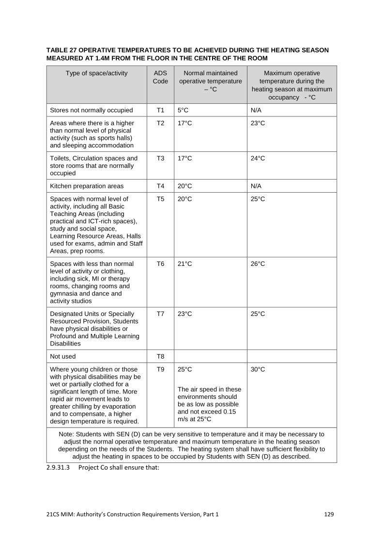
21CS MIM: Authority’s Construction Requirements Version, Part 1 129
TABLE 27 OPERATIVE TEMPERATURES TO BE ACHIEVED DURING THE HEATING SEASON
MEASURED AT 1.4M FROM THE FLOOR IN THE CENTRE OF THE ROOM
Type of space/activity ADS
Code
Normal maintained
operative temperature
– °C
Maximum operative
temperature during the
heating season at maximum
occupancy - °C
Stores not normally occupied T1 5°C N/A
Areas where there is a higher than normal level of physical activity (such as sports halls) and sleeping accommodation
T2 17°C 23°C
Toilets, Circulation spaces and store rooms that are normally occupied
T3 17°C 24°C
Kitchen preparation areas T4 20°C N/A
Spaces with normal level of activity, including all Basic Teaching Areas (including practical and ICT-rich spaces), study and social space, Learning Resource Areas, Halls used for exams, admin and Staff Areas, prep rooms.
T5 20°C 25°C
Spaces with less than normal level of activity or clothing, including sick, MI or therapy rooms, changing rooms and gymnasia and dance and activity studios
T6 21°C 26°C
Designated Units or Specially Resourced Provision, Students have physical disabilities or Profound and Multiple Learning Disabilities
T7 23°C 25°C
Not used T8
Where young children or those with physical disabilities may be wet or partially clothed for a significant length of time. More rapid air movement leads to greater chilling by evaporation and to compensate, a higher design temperature is required.
T9 25°C
The air speed in these environments should be as low as possible and not exceed 0.15 m/s at 25°C
30°C
Note: Students with SEN (D) can be very sensitive to temperature and it may be necessary to adjust the normal operative temperature and maximum temperature in the heating season
depending on the needs of the Students. The heating system shall have sufficient flexibility to adjust the heating in spaces to be occupied by Students with SEN (D) as described.
2.9.31.3 Project Co shall ensure that:
21CS MIM: Authority’s Construction Requirements Version, Part 1 130
for all pumped systems, the initial stage of frost protection is to enable the pumps
in the event that the internal temperature of the Building drops to 5°C (this
temperature shall be adjustable);
in the event that the temperature drops to below 2°C, (this temperature shall also
be adjustable) then the second stage of frost protection commences and the heat
generating plant circulates the heating medium around the system; and
in addition, trace heating is provided on systems at a higher risk to frost protection
(for example systems that run externally fabric or in unconditioned areas of the
Building.
2.9.32 Heating Emitters
2.9.32.1 Project Co shall ensure that any space or area can be heated by one or more of the following emitter types:
natural convectors and radiators;
warm air, including over-door air curtains;
radiant heating (LTHW radiant heating allowable only where the heat source
supports higher flow tempertaures, i.e; biomass boiler, CHP engines. For gas
fired boilers maximising the condensing operation must be paramount and
therefore LTHW radiant heating will not be allowed with this type of central plant,
nor with ASHP/GSHP heat sources);
underfloor heating; and
forced convection fans.
2.9.32.2 Where proposing an alternative form of heat emitter where appropriate for the installation, Project Co shall provide the Authority with detailed reasons and justification.
2.9.32.3 Project Co shall select any heat emitter based on the following requirements:
heating capacity required;
the responsiveness required due to change of use in the space;
thermal comfort requirements;
space available (whether space is available on the floor, around the perimeter or
at high level);
safety requirements (including low surface temperature);
robustness; and
running cost.
2.9.32.4 Project Co shall ensure that:
the materials used in any heat emitters are appropriate for the pipework and
boiler systems connected e.g. steel radiators, steel pipe, stainless steel heat
exchangers;
appropriate water treatment corrosion inhibitors are used;
the heat emitters and system are selected with the ventilation and cooling
strategy in mind in order to reduce energy loss e.g. heating energy lost through
open windows in mid-season and wintertime;
an even temperature gradient is achieved in the room for thermal comfort and
that draughts are reduced or eliminated in the teaching spaces;
21CS MIM: Authority’s Construction Requirements Version, Part 1 131
all emitters are accessible for cleaning, especially those mounted at high level,
and measures shall be taken to prevent dust build-up in/on the heat emitters. All
trench heaters shall be provided with a removable grille for ease of maintenance;
heat emitters do not create noise in the occupied space above the indoor ambient
noise level given in BB93 for the type of space; and
heat emitters must be located in an appropriate position within the room to ensure
an even distribution of heat. Where natural ventilation openings or hybrid fan
assisted ventilation, units are used for ventilation in winter, heat emitters must be
positioned locally (within 1.5m in plan) to the window or fan assisted device to
ensure a local heat source is available to offset cold draughts.
all major building entrances and exits with high frequency of use or traffic during
class change or at the start and end of each day, including visitor doors, are
provided with an over-door air curtain, fed from the buildings LTHW heating
system (electric air curtains not to be used unless written approval from the
Authority) and suitabley sized to cover the entire width of the door opening
+150mm over each end, and selected to provide sufficient terminal velocity at
floor level to offset cold draughts whilst operating in accordance with relevant
acoustic design criteria.
all other external doors in regular use to teaching spaces and occupied rooms
may be provided with either over door air curtains (as described above) or to use
LTHW warm air fan convectors as the primary heat source for the room/space,
sized to provide a quick reaction to open door heat loss whilst operating in
accordance with relevant acoustic design criteria.
2.9.32.5 Project Co shall ensure that the following requirements are met:
where radiators are provided in Nursery and Reception Classrooms and in SEN
(D) dedicated spaces, Designated Units or Specially Resourced Provision, they
are low surface temperature (LST);
all radiators are provided with lockable thermostatic valves (TRVs) or other
control device which shall not allow the room to be heated more than 2⁰C above
the normal room temperature, but also afford frost protection if the valve is closed;
adequate wall space is available for radiators to be coordinated with fixed
furniture allowing unobstructed heat output; and
where trench heating is installed, it is of a robust nature to withstand furniture and
changes of use in the space.
2.9.32.6 Project Co shall ensure that where a sports hall is served by LTHW radiant heaters, they are provided with adequate protection from damage by sports equipment.
2.9.32.7 Project Co shall size radiant panels in accordance with these ACRs and the latest version of BB101 to show that radiant heating complies with the thermal comfort criteria for radiant temperatures.
2.9.32.8 Any underfloor heating shall be based on a LTHW rather than an electric system in order to conserve energy.
2.9.32.9 Fan convectors shall be designed to be robust and easily maintained to prevent dust build up.
2.9.32.10 Where heating is provided via air handling units, integral air source heating pumps shall be used in preference to LTHW and electrical heater batteries.
2.9.33 Radiant Temperature Difference
21CS MIM: Authority’s Construction Requirements Version, Part 1 132
2.9.33.1 In any space where the heating system incorporates overhead radiant panels, Project Co shall undertake calculations as described in the latest version of BB101 to determine the Radiant Temperature Asymmetry (RTA) within each space.
2.9.33.2 The design shall take account of the mean water temperature, size of radiant panels and the available mounting height. Mounting too low can result in occupants complaining of excessive temperatures above their head and if mounted too high, occupants may not feel the full heating benefit.
2.9.33.3 Once the mounting height is established within a space, the arrangement of radiant panels shall allow sufficient separation between the units to provide an even spread of heat throughout the space whilst preventing a crossover of the radiant flow of heat between panels resulting in zones of intense heat.
2.9.33.4 Radiant panels shall not be located directly above teaching walls or other areas where a teacher or other occupant is likely to be standing for prolonged periods of time, unless RTA calculations can demonstrate that the installation is suitable and would not result in excess temperature differences.
2.9.33.5 If the radiant panels are offset from the preferred layout as part of the Service Infrastructure coordination, the impact on RTA shall be assessed. The options of integrating luminaires and acoustic absorbers within radiant panels shall be considered.
2.9.33.6 The surface temperature of ceiling mounted radiant panels in Classrooms or offices and in normal height teaching spaces shall be limited to meet BS EN 15251, which requires that for a category III Building the vertical air temperature difference in the space during the heating season shall be less than 2 K/m in the occupied zone in order to avoid discomfort and to conserve energy. Where radiant panels are used in spaces over 4m in height, measures shall be taken where necessary to reduce stratification.
2.9.33.7 In single storey spaces, the vertical air temperature difference in the space during the heating season shall be <2Km-1 and the asymmetric radiant temperature difference to hot ceilings shall be less than 10oC except for a short recovery period after outside doors are closed. It will be necessary to limit the surface temperature of ceiling mounted radiant panels in Classrooms or offices and in normal height teaching spaces to achieve this (Ref: CIBSE Guide A, 1.5.6 and 1.5.9); account is taken of heat gains to spaces so that heat emitters are not over-sized.
2.9.34 Underfloor Heating
2.9.34.1 If under-floor heating is used, Project Co shall be able to demonstrate that all spaces will neither take too long to recover their temperature following sudden heat losses, nor overheat due to increased heat gains following sudden heat loss (for example where external doors are opened), changes in occupancy or equipment heat load.
2.9.34.2 Project Co shall ensure that, where underfloor heating is provided, the following requirements are met:
maximum surface temperatures: comply with these ACRs and the latest version
of BB101;
where there are nursery-age children, children with complex health needs, Project
Co shall ensure that the maximum surface temperature of floors with under-floor
heating shall be 26oC ± 2oC, the comfort temperature for low activity. This
temperature shall also not be exceeded where children are likely to be sitting on
the floor;
21CS MIM: Authority’s Construction Requirements Version, Part 1 133
top of screed temperature sensors are installed into each underfloor circuit or
zone of control to monitor and control the maximum screed surface temperature,
all as part of the underfloor heating temperature control system. The temperature
sensors shall be a thin film or bulb type inserted into a shallow recess directly on
top of the screed and beneath the floor finish so as to be easily accessible for
maintenance and replacement. Cast in temperature sensors shall not be used;
the floor covering is appropriate for underfloor heating to allow effective heat
transfer to the room;
the design and installation is fully coordinated with other under-floor Service
Infrastructure such as drainage and electrical cables, and any fixed Equipment;
actuators and manifolds are located in a dedicated cupboard or robust boxing
adjacent to the space being heated but inaccessible to Students and the public;
and
the pipework, valves and connections are designed in order to avoid in-screed or
underfloor leaks;
2.9.34.3 If the screed depth is reduced to increase the response time, consideration is given to the static and dynamic loads placed on the floor. The construction method and materials proposed to provide a reduced screed depth shall be submitted to the Authority for approval.
2.9.34.4 Project Co shall not install underfloor heating where:
the room use, and heating profile will change quickly since underfloor heating is a
slow response system;
floors may be covered with mats (e.g. in soft play rooms in a Designated Unit);
regular spillages can cause hygiene and odour problems (e.g. in toilets, changing
rooms or Hygiene Rooms);
the positions of partition walls are likely to change in future years such as in Basic
Teaching spaces;
fixings are required into the screed for furniture (e.g. lab benches) or equipment
(e.g. in Design and Technology)’; and
there is bleacher seating.
2.9.35 LTHW Pipework
2.9.35.1 Project Co shall ensure that, in all LTHW systems provided meet the following requirements:
the main heating distribution pipework is routed such that it is concealed
throughout, except for final drops to heat emitters. Pipework, valves and
ancillaries are accessible for maintenance;
pipework drops on low surface temperature (LST) pipework are concealed;
the main heating pipework is run in corridors at high level and branches off to
serve individual rooms;
wherever possible pipework runs at high level and drops to low level to connect to
heat emitters as required. This does not preclude emitters being served from
below in the event that this is the optimum route. Where it is proposed to serve
emitters from below this shall be approved by the Authority;
all distribution pipework is installed with drain down and isolating valves, to allow
the system to be drained in its entirety;
21CS MIM: Authority’s Construction Requirements Version, Part 1 134
automatic air vents are provided at the top of all risers and on high points within
the system. Pipework is laid to fall wherever possible to minimise the number of
high points;
pipework is installed to allow easy self-venting and commissioning. The flushing
of hot and cold-water systems complies with BS EN 806-4;
any concealed underfloor heating system pipework is pressure tested and
witnessed before any final floor covering is applied; and
all indoor AC units and DX coils are fitted with a condensate drain. Condensate
wastes shall be connected to the main drainage system via a running trap in a
waste guaranteed to carry waste regularly.
2.9.36 LTHW Valves, Fittings and Components
2.9.36.1 Project Co shall ensure that, in any LTHW valves, fittings and components provided, the following requirements are met:
a micro-bubble de-aerator, dirt separator and strainer are installed on the
common heating return pipe of all heating systems;
micro-bubble de-aerators, dirt separators and strainers are installed on the
primary and secondary heating return pipes where plate heat exchangers are
installed;
provision for expansion/contraction of water within the system and cold-water
feed is provided either by a packaged pressurisation unit with heating system
quick fill facility or a feed and expansion tank. The “make-up” water to heating
systems shall be independently sub-metered and monitored by the Building
Management System (BMS) to alert the Authority and the relevant School Entity in
the case of a school(s) Project] to any unexpected water usage which would indicate
a leak in the system;
quick fill units and expansion tanks are located and insulated so that they cannot
easily freeze;
expansion vessels are adequately sized for the full water content of the circuit,
with at least 2no. independent vessels provided for resilience;
where a feed and expansion tank is installed, it is of sufficient capacity and in
suitable condition for the proposed development;
heating circuit design enables flow balancing under all load conditions;
differential pressure control valves are provided on the heating supplies to groups
of radiators in order to provide system stability and flow control;
isolating valves, check valves, expansion valves and double regulating valves are
installed appropriately to aid commissioning, giving consideration for access and
maintenance;
test points, temperature and pressure relief valves, temperature and pressure
gauges and draining devices are provided to aid commissioning and balancing;
automatic air vents are provided to aid balancing in the system;
pipework and supports take account of axial expansion;
dosing pots are provided in the plant room for addition of corrosion inhibitors and
other water treatment chemicals; and
adjustable valves are provided in break tanks to allow the storage quantity to be
adjusted.
2.9.36.2 Project Co shall pressure test all pipework systems.
21CS MIM: Authority’s Construction Requirements Version, Part 1 135
2.9.36.3 Project Co shall include details of the water treatment regime to prevent corrosion and sludge formation in heating systems in the operation and maintenance manual, together with details of commissioning tests and routine tests and dosing. Project Co shall also provide a means of dosing the system.
2.9.36.4 Project Co shall ensure that the design and installation of the heating system:
is robust and durable, to withstand accidental or Malicious Damage;
includes duty and standby boilers and pumps, to ensure that the Facility can
function when minor failures of the system occur. Two boilers sized at 66% of the
full load and twin head pumps are adequate provision;
is flexible enough to provide multi-functional use, including third party use of the
Buildings (where specified in the relevantSite Specific Brief), without loss of
energy efficiency and the use of complex control and operating systems;
routes heating pipes in co-ordination with other Service Infrastructure and the
Building's structure so that major disruption to the Facility is avoided as a result of
Programmed Maintenance or Unprogrammed Maintenance
routes piped water services so as to avoid rooms or areas where leaks would
cause considerable disruption and financial loss;
ensures surface temperatures of heat emitters and associated pipework are safe
(see below);
includes valve isolation such that isolation of circuits/ sub-circuits does not disrupt
heating to the remaining Building; and
includes frost and anti-condensation protection.
2.9.36.5 For standard radiators, a surface temperature of 60-70ºC is commonly used. If this is proposed for a Project, Project Co shall carry out a risk assessment for young children and children with SEN (D). Students’ additional requirements are described in the relevant Site Specific Brief. Where there are nursery-age children or those with complex needs, Project Co will provide low surface temperature radiators (not greater than 46ºC) and protection from hot pipework where they are within reach of Students.
2.9.36.6 Project Co shall provide zoned systems matched to occupancy areas. Occupied zones must have variable temperature controls and permit zoning for out of hours use. Individual thermostatic control shall be provided to each occupied room or space, e.g., by thermostatic radiator valves
2.9.36.7 Heating and thermal comfort in Designated Units or Specially Resourced Provision
2.9.36.8 Where children are non-ambulant, or have low activity rates, Project Co shall provide individual tamper-proof room controls, in any space that is used for more than a transitory period. Where Students are likely to overheat at a lower temperature than other Students or are vulnerable to the effects of dust and to infection, this will be noted in the relevant Site Specific Brief and Project Co shall take measures to ensure Students remain comfortable. See paragraph2.9.42 on Infection Control.
2.9.36.9 Project Co shall provide:
localised supplementary heating and cooling if necessary to achieve the required
temperatures; and
measures to control heat gains, such as shading devices for solar control.
2.9.36.10 Project Co shall take account of any specialist equipment that could raise the temperature of a space.
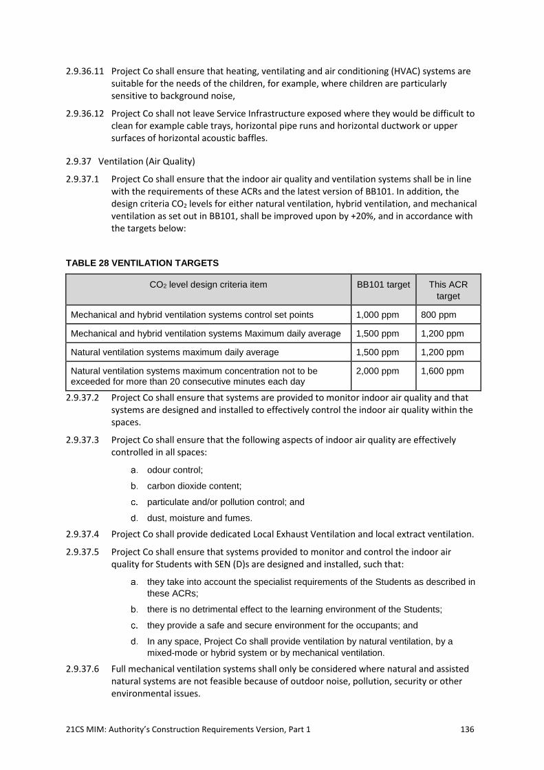
21CS MIM: Authority’s Construction Requirements Version, Part 1 136
2.9.36.11 Project Co shall ensure that heating, ventilating and air conditioning (HVAC) systems are suitable for the needs of the children, for example, where children are particularly sensitive to background noise,
2.9.36.12 Project Co shall not leave Service Infrastructure exposed where they would be difficult to clean for example cable trays, horizontal pipe runs and horizontal ductwork or upper surfaces of horizontal acoustic baffles.
2.9.37 Ventilation (Air Quality)
2.9.37.1 Project Co shall ensure that the indoor air quality and ventilation systems shall be in line with the requirements of these ACRs and the latest version of BB101. In addition, the design criteria CO2 levels for either natural ventilation, hybrid ventilation, and mechanical ventilation as set out in BB101, shall be improved upon by +20%, and in accordance with the targets below:
TABLE 28 VENTILATION TARGETS
CO2 level design criteria item BB101 target This ACR
target
Mechanical and hybrid ventilation systems control set points 1,000 ppm 800 ppm
Mechanical and hybrid ventilation systems Maximum daily average 1,500 ppm 1,200 ppm
Natural ventilation systems maximum daily average 1,500 ppm 1,200 ppm
Natural ventilation systems maximum concentration not to be exceeded for more than 20 consecutive minutes each day
2,000 ppm 1,600 ppm
2.9.37.2 Project Co shall ensure that systems are provided to monitor indoor air quality and that systems are designed and installed to effectively control the indoor air quality within the spaces.
2.9.37.3 Project Co shall ensure that the following aspects of indoor air quality are effectively controlled in all spaces:
odour control;
carbon dioxide content;
particulate and/or pollution control; and
dust, moisture and fumes.
2.9.37.4 Project Co shall provide dedicated Local Exhaust Ventilation and local extract ventilation.
2.9.37.5 Project Co shall ensure that systems provided to monitor and control the indoor air quality for Students with SEN (D)s are designed and installed, such that:
they take into account the specialist requirements of the Students as described in
these ACRs;
there is no detrimental effect to the learning environment of the Students;
they provide a safe and secure environment for the occupants; and
In any space, Project Co shall provide ventilation by natural ventilation, by a
mixed-mode or hybrid system or by mechanical ventilation.
2.9.37.6 Full mechanical ventilation systems shall only be considered where natural and assisted natural systems are not feasible because of outdoor noise, pollution, security or other environmental issues.
21CS MIM: Authority’s Construction Requirements Version, Part 1 137
2.9.37.7 Any ventilation system provided shall be developed to provide fresh air for occupants and maintain/control the indoor air quality (pollutants, CO2, odours, VOCs) throughout the year. Ventilation should also be considered to meet the requirements for purge and night time cooling as part of the summertime cooling strategy. VOC sensors are not required as part of the system.
2.9.37.8 Project Co shall ensure that external noise levels from any ventilation and extract systems provided do not exceed local planning requirements in accordance with the Institute of Acoustics/Acoustic Noise Consultants School Design Guide. Mechanical ventilation shall not create excessive noise. Indoor ambient noise levels shall comply with BB93.
2.9.37.9 Any and all mechanical ventilation systems must be designed to operate on a balanced building approach such that the sum of all extract rates shall match the sum of all supply rates. Internally, local regimes can still be applied to promote negative imbalance or air movement towards sources of smells and odours, such as Kitchens and toilets, but overall, the Building must be in balance.
2.9.37.10 Any mechanical ventilation systems provided shall be either centralised systems serving multiple rooms or local room-level systems.
2.9.37.11 Project Co shall design and provide a balanced supply and extract ventilation system for the whole Building. A single supply and extract air handling unit with heat recovery serving a centralised ventilation system is the preferred solution, with tempered fresh air supply to occupied rooms that need it, and air transfer via ducted and attenuated grilles to corridors, being used as make up air for WC extract. Where internal rooms require additional ventilation to meet thermal comfort criteria, Project Co shall consider whether it is more economic to increase the ventilation rate using outside air at summertime temperatures and increase plant and ductwork distribution sizes appropriately or introduce peak lopping cooling using integral IAHSP’s within the air handling unit.
2.9.37.12 For centralised systems, the use of IASHP air handling units, with both indoor and outdoor coils in the supply and extract air streams, are to be the primary consideration when selecting any such air handling unit (AHU). Where peak lopping cooling may also be required to supply air streams, then the IASHP should be a reversible type to operate in either heating or cooling mode.
2.9.37.13 Any air handling unit used in centralised systems shall be located in plant rooms or accessible roof voids, rather than externally mounted on roof areas.
2.9.37.14 Mechanical ventilation shall be used to negatively pressurise any areas where there are unwanted odours, including Dining and Social areas, Kitchens, food rooms, and toilets. Where appropriate, ventilation systems shall be interlocked with the gas supply in accordance with IGEM/UP/19.
2.9.37.15 All ductwork and plenums shall be fully accessible for cleaning.
2.9.37.16 Project Co shall ensure that where mechanical ventilation is used enough fresh air is provided to achieve a daily average concentration of carbon dioxide during the Core Day of less than 800ppm and so that the maximum concentration does not exceed 1,200ppm for more than 20 minutes each day.
2.9.37.17 Project Co shall ensure that where natural ventilation is used, the system is capable of providing enough fresh air so that the average concentration of carbon dioxide during the Core Day is less than 1,200ppm and so that the maximum concentration does not exceed 1,600ppm for more than 20 minutes each day.
21CS MIM: Authority’s Construction Requirements Version, Part 1 138
2.9.37.18 Project Co shall endeavour to design natural, mechanical or hybrid ventilation systems to meet the space heating and thermal energy targets given in the Energy and Utilities paragraphs of these ACRs.
2.9.37.19 Natural ventilation may be provided through one or more of the following, or through an alternative as long as full justification is provided, and agreed to by the Authority:
openable windows (actuated or manual);
louvres with dampers (actuated or manual);
openable inwards windows (actuated or manual) with external louvres; and
roof mounted units that utilise the stack and wind effect (may be fan assisted).
2.9.37.20 Project Co shall ensure that any openable windows and vents provided are designed to avoid inhibiting the effective use of any blinds used for glare control, or for blackout in Practical and Vocational Teaching areas and Performance Spaces.
2.9.37.21 Where actuators are used, for actuated window or louvre natural ventilation openings, these shall be electrically driven from low voltage 24v DC regulated power supplies and designed to be appropriate and suitably rated for the type of opening that they are driving open and/or closed. They shall be normally quite in operation so as not to distract the occupants of the space. They shall be continuously rated for a minimum of 10,000 cycles. If more than one actuator is provided to a single opening the actuators must be synchronised for speed and time of operation. All actuators must include for entrapment monitoring and release functions. All actuators must be fully modulating to be able to be controlled either automatically or manually to within 1mm. All actuators must include for fault monitoring and reporting to the BMS. In multiple occupancy rooms, the default operation of an actuated opening should be automatic. Where actuators are to be automatically controlled they shall be operated and modulated in response to demand driven temperature and/or CO2 level sensors, as such they must be controlled via the BMS and include for local over-ride controls accessible only by the Authority (or the the relevantSchool Entity staff in the case of a School(s) project).
2.9.37.22 Actuator local over-ride controls shall comprise a single or twin-gang switch plate with a retractive push button and indicator lights to cycle through either automatic operation, manual operation (with separate push buttons for open/close) or over-ride off. The manual controls will default to auto at the end or start of the next BMS timeclock period.
2.9.37.23 Where actuated openings are automatically operated, and they are subject to external weather penetration, they shall include for BMS networked rain-sensing controls to over-ride close. This may be manually over-ridden by the occupant via the manual over-ride control as described before. Where louvres are used as part of a natural ventilation strategy, their visual free area and discharge coefficient (Cd) are to be taken into account when calculating and determining the overall equivalent free area. All such data used will be accredited tested data provided by the louvre manufacturer.
2.9.37.24 Where possible, the Building geometry should be designed to allow cross-ventilation or stack effect ventilation.
2.9.37.25 Attenuation of natural ventilation shall be provided where necessary to meet BB93 indoor ambient noise levels where external noise levels are high.
2.9.37.26 Project Co shall ensure that:
restrictors or external louvres are installed on all windows to prevent falls;
secure louvres or openings are provided for night cooling where an exposed soffit
and/or thermal mass has been used as part of the thermal strategy;
21CS MIM: Authority’s Construction Requirements Version, Part 1 139
any openable roof lights or roof vents shall be designed to provide ease of use by
the Authority or the School Entity/(ies) staff in the case of a School(s) Project, and
any natural ventilation systems to large spaces, or serving multiple spaces, such
as Halls and Atria shall be designed to be electrically driven and automatically
operated by CO2 and temperature sensing demand controls, as described before.
They shall also be provided with wind speed and wind direction compensation
controls, to further modulate the actuator to reduce over-shoot and draughts.
2.9.38 Fans
2.9.38.1 Where a mechanical or mixed-mode system is installed, the options to provide ventilation through fans to a Facility include:
fan assisted natural ventilation (either through a facade, atrium system or roof);
local ventilation supply and/or extract fans;
specialist Local Exhaust Ventilation; and
anti-stratification fans.
2.9.38.2 Project Co shall ensure that any fans provided:
are energy efficient and comply with Building Regulations AD L;
where serving multiple rooms or spaces they are provided with velocity sensors to
control the fan operation and speed by inverter speed controls; and
where mounted at high level are accessible for installation, maintenance and
removal.
2.9.39 Air Handling Units
2.9.39.1 Centralised mechanical ventilation shall be provided through one or more air handling units . Air handling units shall include filters, inverter controlled variable speed plug fans with velocity sensors to control the fan operation and speed by inverter speed controls, acoustic insulation and attenuators as necessary to meet BB93 noise levels. Project Co shall ensure that the correct level of filtration is provided in line with Regulations including AD F and local planning requirements.
2.9.39.2 The air handling Units shall include a remote filter status indication.
2.9.39.3 Where an air handling unit provides mechanical supply and extract it shall contain heat recovery, except when used for Kitchens. Heat recovery can either be achieved through:
cross flow or plate heat exchanger; or
thermal wheel.
2.9.39.4 Where an air handling unit provides balanced mechanical supply and extract and requires a leaving air temperature at peak design higher than can be provided by the heat recovery device alone, or it is required to provide peak lopping cooling, it shall contain an integral air source heating pumps (IASHP), except when used for Kitchens. The IASHP removes any requirement for wet coils within air handling units and is therefore not subject to any risk of freezing. The IASHP air handling unit will comprise of the following components:
Evaporator coil in exhaust air stream, and condenser coils within supply
airstreams, after heat recovery device, reversible if required for heating and/or
cooling operation;
21CS MIM: Authority’s Construction Requirements Version, Part 1 140
Integrated compressor enclosure with at least 2no. scroll compressors on 2no.
independent refrigeration circuits, and with a minimum of 50% of the load being
met by a digital scroll compressor for variable output at part load conditions; and
Fully packaged integral control panel for synchronised operation of air stream
controls with the refrigeration controls.
2.9.39.5 Project Co shall ensure that an appropriate air handling unit is selected based on energy efficiency and space requirements.
2.9.39.6 Project Co shall position any discharge air terminals to prevent re-circulation into the Building.
2.9.39.7 Any exhausts or intakes provided shall be adequately separated when exhaust air is contaminated or polluted, e.g. exhausts from Kitchens, toilets and fume cupboards.
2.9.39.8 In accordance with DW/172, Kitchen extract discharge points shall be positioned such that the extracted air cannot be entrained into a supply system. The ductwork shall discharge at least 1.0 m above any openable window or any ventilation inlet or opening. Kitchen extract air will be exhausted to atmosphere by a high velocity vertical discharge duct arrangement.
2.9.39.9 Flues shall be high enough above any roof so as to ensure that the fumes are discharged clear of the roof recirculation zones and cannot re-enter the Building or any adjoining Building in accordance with the latest version of BB101.
2.9.39.10 For any hazardous fume exhaust systems provided, the methods described in ‘Fume Cupboard Exhausts’ shall be used to determine height and location of fume cupboard exhausts.
2.9.39.11 Where stack heights are limited, e.g., by planning constraints, it will be necessary to increase the plume height by increasing the efflux velocity.
2.9.39.12 Fire dampers shall not be installed in exhaust discharge ductwork from fume cupboards or other fume exhaust systems or Kitchen exhaust systems except where Project Co allows for an intumescent type only where when using plastic extract ductwork in science labs it will otherwise be difficult to provide alternative fire protection.
2.9.39.13 Project Co shall ensure window and vent operating mechanisms in Classrooms are virtually silent to avoid distraction during lessons. To be acceptable in Classrooms, the noise of actuators (at normal speed) when measured in the occupied zone in the middle of the room shall not give rise to more than a 3 dB increase in the indoor ambient noise level specified for the space over the period of operation.
2.9.39.14 Project Co shall ensure that the School is designed so that the air speed flowing across occupants in winter is <0.3 m/s in all teaching spaces. Where pupils may be partially clothed this should be reduced to < 0.15m/s.
2.9.39.15 In naturally ventilated Classrooms, Project Co shall provide effective coupling of the ventilation air with thermally massive elements intended to provide passive cooling through use of thermal mass. This will prevent summertime overheating of the room and excess asymmetric radiation from a warm ceiling. Project Co shall design an effective free opening area (Aeff) of at least 5% of the floor area with the top of the opening within 200mm of ceiling or exposed soffit level, whichever is the higher. This is required for effective summertime ventilation and cooling of the ceiling or soffit. Project Co will not include downstand beams which prevent this. Project Co shall control any night cooling of thermal mass in soffits or ceilings to prevent over-cooling of the thermal mass, for example, by means of a temperature sensor embedded in the first 70mm of the surface.
21CS MIM: Authority’s Construction Requirements Version, Part 1 141
2.9.39.16 Project Co shall ensure that the rejection of energy laden warm or cool air is minimised in the Building through the use of ventilation systems which limit the pre-heating of ventilation air and exploit the heat gains from occupancy and equipment and by control of the ventilation heat loss through external doors. Project Co shall provide all main entrance doors with draft lobbies.
2.9.39.17 Project Co shall ensure that HVAC systems are easily accessible for maintenance, so that measures can be taken to ensure children are not exposed to the bacteria found in moist conditions in ductwork.
2.9.40 Local Extract Ventilation
2.9.40.1 Project Co shall provide intermittent extract ventilation in accordance with these ACRs and the
latest version of BB101 to:
sanitary accommodation and washrooms;
rooms containing printers and photocopiers in substantial use; and
food and beverage preparation areas.
2.9.40.2 Project Co shall ensure that extract ventilation is taken to the outside and provided with appropriate time and occupancy controls and where possible, extract ventilation shall include a means of heat recovery.
2.9.40.3 Project Co shall ensure that ventilation to offices is in accordance with AD F1 Table 6.1b, which requires the total outdoor supply rate for offices to be 10l/s/person. Project Co shall take into consideration the appropriate CIBSE guidance for the ventilation of various types of accommodation including, assembly halls, Atria, plant rooms, laboratories28, sports centres and swimming pools.29
2.9.40.4 For any toilet area, or where all toilet cubicles open directly off the corridor, extract shall be provided by using the central air handling unit system (with heat recovery), with the make-up air taken from the surrounding corridors and internal spaces.
2.9.40.5 The air handling unit will supply tempered fresh air to the occupied rooms that require it. This air will transfer into corridors, via grilles and ducted and attenuated transfer paths, to be then used as makeup air for the WC extract. Using the fresh air in this manner will assist with ventilating Circulation corridors, recover heat from the WC exhaust air and will provide energy saving for reduced whole Building ventilation rates.
2.9.40.6 A whole Building single ventilation air handling unit with heat recovery will provide the optimum solution, with tempered fresh air supply to occupied rooms that need it, and air transfer via ducted and attenuated grilles to corridors, being used as make up air for WC extract.
2.9.40.7 All extract air will be provided with heat recovery to the supply air stream using either cross plate heat recovery devices or thermal wheels, with minimum heat recovery efficiencies to EU regulation 1253/2014 (more commonly known as the Ecodesign Directive or the ErP Directive).
2.9.40.8 Where full height cubicle partitions are specified in toilets, make up air shall be provided either by a ventilation air path that preserves acoustic and visual privacy including from mobile phone cameras, or supply air must be provided to the cubicle.
28 See also CLEAPSS guide G14 Designing and planning laboratories (05/09), www.cleaps.org.uk 29 Refer to Table 6.3 of Approved Document AD F1 2010.
21CS MIM: Authority’s Construction Requirements Version, Part 1 142
2.9.40.9 In any Kitchen, extract fans shall be fitted with a variable speed inverter control, attenuation and grease and particle filtration. The Kitchen extract system shall be interlinked with the gas supply.
2.9.40.10 Project Co shall ensure that adequate and controlled make-up air is provided where extract ventilation is used.
2.9.40.11 This section gives the requirements for any extract ventilation, e.g. from toilets, washrooms, photocopiers and printers. Minimum local air extract ventilation rates are given in BB101 table 5-1.
2.9.40.12 Project Co shall note the rates of ventilation for sanitary accommodation and wash rooms required as detailed in Table 29 below, which improve on those in BB101.
TABLE 29 MINIMUM WASHROOM EXTRACT VENTILATION RATES
Room Local extract
Sanitary accommodation and washrooms. • 15 l/s per shower head/bath; or 8 ac/hr of room volume* (whichever is greater)
• 6 l/s per WC/urinal; or 6 ac/hr of room volume* (whichever is greater)
Individual facilities can use intermittent air-extract but combined facilities opening off Circulation areas shall have continuous extract with a peak rate of 6 achr; a reduced continuous background rate of 4l/s/appliance can be used where there is occupancy sensor control of the higher peak rate.
Notes: * Room volume is the total toilet or shower and changing room area, not just the cubicle area
2.9.40.13 Extract ventilation shall be taken to the outside and provided with appropriate time and occupancy controls.
2.9.41 Ventilation for SEN (D)
2.9.41.1 The following is a minimum specification for the design and installation of ventilation in Designated Units or Specially Resourced Provision.
2.9.41.2 The design of ventilation systems for Students with SEN (D) in non-ambulant Designated Units or Specially Resourced Provision shall:
minimise recirculation to mitigate risk of cross-infection; areas with complex
health and hygiene requirements may require precise control of air flows with
pressure regimes, depending on the needs of the Students; and
ensure allergen and pollutant circulation is kept as low as necessary, this may
require filtration depending on the needs of the Students and the local external air
quality.
2.9.41.3 Project Co shall ensure that the ventilation for teaching spaces in a Designated Unit or Specially Resourced Provision takes account of the typical occupant density (typically around 8 Students compared to 30 in mainstream School accommodation). A design rate per person is not always appropriate, although the general requirements and advice on ventilation shall be adopted.
2.9.41.4 Project Co shall ensure that an assessment of the requirements of the occupants is undertaken before commencing the ventilation system design. This is to ensure that any
21CS MIM: Authority’s Construction Requirements Version, Part 1 143
specific needs of the occupants are catered for, as the requirements of SEN (D) accommodation vary considerably depending upon the nature of the occupants.
2.9.41.5 Ventilation in SEN (D) accommodation shall provide the minimum ventilation rates given in BB101 Table 5-6
2.9.41.6 Laundries, soiled holding or waste, and cleaners’ rooms shall be ventilated by means of mechanical extract with natural or mechanical make-up air. Toilets for Students with complex health needs and Hygiene Rooms shall be ventilated by means of mechanical extract to outside, with make-up air, heated and filtered. Toilets, showers, changing areas, laundries, cleaners’ rooms and spaces holding soiled clothes or clinical waste shall be mechanically ventilated to achieve a slight negative pressure relative to adjacent spaces.
2.9.41.7 Ventilation design shall not compromise acoustic performance, particularly where Students have additional sensitivities to noise.
2.9.41.8 Ventilation systems shall be controllable and adjustable, according to the needs of individual Students. Air conditioning shall be avoided.
2.9.42 Infection Control
2.9.42.1 Where there are Students with complex health needs, ventilation systems shall be designed for infection control and to maintain standards of hygiene in accordance with the latest version of BB101. Staff shall be able to control ventilation for comfort, and draughts shall be minimised so as not to affect vulnerable and immobile Students. Legionella is a higher risk to people with complex health needs, some of whom may be immuno-compromised. Particular attention needs to be paid to legionella prevention in domestic hot water systems and in any adiabatic cooling systems in these schools.
2.9.42.2 Where mechanical ventilation is specified, Project Co shall provide filtration, depending on external air quality and design exposure levels.
2.9.42.3 Some Students in Designated Units or Specially Resourced Provision may be very vulnerable to infection. In these cases, Health Technical Memoranda, specifically HTM 03-01 Part A, published by NHS Estates shall be consulted and it is essential that infection control policies are in place and implemented. Managing cross-infection is a complex subject, but the risks of cross-contamination can be reduced through adequate source control.
2.9.43 Specialist ventilation
2.9.43.1 The following sections detail the technical requirements for a number of specialist ventilation systems within the Facilities.
2.9.44 Kitchen Ventilation:
2.9.44.1 Project Co shall design the Kitchen ventilation system in accordance with DW/172 and the latest version of BB101 and ensure:
a. maximum internal ambient noise levels shall be in accordance with BB93, 50 LAeq,
30mins dB for new build and 55 LAeq, 30mins dB for refurbishment or remodelling;
b. the method set out in DW/172 for calculating the required extract airflow rate for the
Kitchen canopy or for a ventilated ceiling is used;
c. dedicated supply make-up air systems shall be designed at 85% of the extract flow
rate and leakage paths are to be properly managed; and
21CS MIM: Authority’s Construction Requirements Version, Part 1 144
d. the method set out in BS 6173 in order to calculate the required ventilation to
support combustion for gas appliances is used.
2.9.44.2 Project Co shall ensure that the following requirements are met:
sufficient ventilation is provided to safeguard against the possibility of incomplete
combustion;
an interlock is provided between gas supply and mechanical ventilation to ensure
that gas will not be supplied when an inadequate airflow rate is provided. This is
for safe operation of appliances and the safety of personnel;
the system is fully compliant with the requirements set out in in IGEM/UP/11 ‘Gas
Installations for Educational Establishments’, IGEM/UP/19 and the requirements
for gas services set out in these ACRs;
the system does not cause discomfort to the occupants via draughts. The
incoming supply air shall be pre-heated and distributed within the Kitchen area in
accordance with DW/172;
the discharge from the exhaust of the system is appropriately positioned;
the discharge from the exhaust of the system does not cause discoloration or
damage to any part of the Building's structure or any noise or odour problem to
neighbouring rooms or properties;
maintenance and cleaning schedules shall be included in operation and
maintenance manuals and a Kitchen user guide shall be produced as part of the
Building User Guide;
the Kitchen extract ventilation rate is automatically variable, controlled by an
intelligent control module with sensors in the hood and extract ductwork for:
a. an optic sensor detecting smoke and steam (in hood);
b. a temperature sensor (in ductwork); and
c. A carbon dioxide sensor (for gas fueled cooking),
the supply air flow rate at either condition is tracked to the extract air flow rate to
always be 85% of the extract rate; and
HSE Catering Information Sheet 23 details the risk assessment process that shall
be applied by the contactor for refurbishment and upgrading of installations that
do not meet the requirements for new installations.
2.9.45 Grease Filters and Odour Control
2.9.45.1 Removable baffle type grease filters shall be installed so that they are accessible for cleaning and maintenance. Grease extracted by the ventilation system shall be collected and removed so that it does not accumulate in either the canopy or the ductwork system.
2.9.45.2 DW/172 and Defra guidance summarise the available odour control, filtration, and noise control technologies. The priority should be to provide simple technologies that are easily maintained by the Facility and to provide adequate efflux velocity and flue height to provide good dispersal rather than to employ expensive odour control and filtration systems with a lower flue height and efflux velocity. In general, the flue shall terminate at least 1m above the roof or any air inlet at an efflux velocity of at least 10m/s as recommended in DW/172.
2.9.46 Food Room Ventilation
2.9.46.1 The following section provides a minimum specification for the design and installation of the ventilation and associated systems in any Secondary School or College food rooms.

21CS MIM: Authority’s Construction Requirements Version, Part 1 145
2.9.46.2 Project Co shall use the following criteria:
there is a door between the food room and any linked space such as a food
Preparation Area to prevent contamination from dust;
exhaust ventilation rates shall be calculated taking account of room size and
usage;
during normal cooking activities, noise generated by extraction systems shall not
be loud enough to prevent the Students from hearing the teacher, or the teacher
from hearing the Students’ voices, as this poses a significant hazard. If possible,
it shall be kept below 50 dB or (10dB above the maximum indoor ambient noise
level of 40 dBA required by BB93) in accordance with Section 2.12.2 of the
IoA/ANC 'Acoustics of Schools: a design guide', 2015. Where this is not possible,
higher noise levels of up to 55 dBA will only be acceptable where the teaching
staff have control over the ventilation system and can switch it off locally as
required for teaching. Noise levels during normal teaching and practical activities
shall comply with Section 1.1.3 of BB93. IoA/ANC ‘Acoustics of Schools: a design
guide’, 2015 gives guidance on the higher noise levels allowed during process
related Local Exhaust Ventilation, such as from cooker fume extract systems;
the room shall be kept under a negative pressure during cooking activities;
displacement ventilation systems which extract the hot air from high level and
supply cooler tempered air at low level help to remove heat gains from the
occupied zone and limit the ventilation rates required during cooking activities.
For ventilation of domestic cookers in food rooms where there are up to 13
cookers in the space, there shall be minimum supply and extract of 42 l/s
(150m³/hr) of air per appliance, in accordance with IGEM/UP/11. This may be
reduced where displacement ventilation of high effectiveness is used, and a lower
rate is shown to be adequate;
exhaust ventilation may be in the form of individual extraction hoods, but if used,
these must not obstruct Student sightlines to the whiteboard. Where separate
canopies are used above individual appliances, they shall be designed to have a
flow rate exceeding 42 l/s (150m³/hr). This figure is inclusive of the 8 l/s required
for CO2 control.
2.9.46.3 In these spaces the assumption is that gas hobs will never all be used at the same time at their full rate and will only be used with Students for periods of less than one and a half hours at a time.
2.9.46.4 Mechanical ventilation systems shall be interlocked with the gas supply in accordance with IGEM/UP/11 and IGEM/UP/19.
2.9.46.5 Opening windows will require fly guards to prevent insect contamination unless there is mechanical ventilation providing filtered supply air. Fly guards are required where a ventilation system relies on natural ventilation openings at all times. In this case, the resistance to airflow, or discharge coefficient (Cd) of the fly guards must be taken into account in calculations of effective areas (Aeff) of openings.
2.9.46.6 If refrigerators or freezers are kept in storerooms, ventilation must be sufficient to maintain temperatures in accordance with manufacturers recommended ambient temperatures for the siting of the equipment.
2.9.46.7 Heat recovery on supply and extract systems may be provided to minimise heat losses associated with high ventilation rates when cooker hoods are running.
2.9.46.8 General room extract systems needs to be positioned to avoid excessive build-up of grease with provision made for easy replacement/cleaning of filters.
21CS MIM: Authority’s Construction Requirements Version, Part 1 146
2.9.46.9 Whilst cookers/hobs are not in operation, the ventilation standards shall be the same as a General Teaching space. However, during cooking where using gas fuel, the levels of CO2 given in these ACRs shall be achieved.
2.9.46.10 Project Co shall ensure that the system does not cause discomfort to the occupants via draughts. The incoming supply air shall be pre-heated and distributed within the space as per the guidance set out in DW/172.
2.9.46.11 Project Co shall also ensure that the discharge from the exhaust does not cause discoloration or damage to any part of the Building's structure.
2.9.47 Gas Interlocks
2.9.47.1 An interlock is required between gas supply and mechanical ventilation to ensure that gas will not be supplied when there is an inadequate airflow. This is to ensure the safe operation of appliances and the safety of personnel.
2.9.47.2 Where there are only Type A appliances i.e., there are no flued gas appliances such as deep fat fryers, interlocking may be achieved by environmental monitoring of carbon dioxide as described in IGEM/UP/19, BS 6173 and these ACRs.
2.9.47.3 HSE Catering Information Sheet 23 details the risk assessment process that shall be applied by the contactor for refurbishment and upgrading of installations that do not meet the requirements for new installations.
2.9.48 ICT Server Room Ventilation
2.9.48.1 The following section is a minimum specification for the design and installation of the ventilation and associated systems in Information and Communications Technology (ICT) server rooms and hub rooms within the Facilities.
2.9.48.2 Project Co shall implement environmental control to provide a stable condition for ICT (Air-conditioning (as required)).
2.9.49 General Requirements
2.9.49.1 Typical server rooms can produce high-density heat loads which can affect ICT equipment. Project Co shall ensure that environmental conditions are maintained in line with the manufacturer’s recommendations for the equipment to be housed within, or any respective warranty requirements. Security of ventilation openings in the façade shall comply with the ACR.
2.9.50 Ventilation Systems, Air Flow Rates and Heat Loads
2.9.50.1 The type of ventilation system required and the strategy to cool the server room will be dependent on the heat loads generated by the equipment.
2.9.50.2 If a mechanical ventilation system is used this shall be provided with filtration to prevent dust ingress.
2.9.50.3 Project Co shall ensure that server room cooling units provided are sized on the sensible heat loads provided by the manufacturers of the equipment to be installed (allowing for diversity) or the actual measured power consumption of the equipment. Where this information is unavailable half the nameplate ratings of the equipment can be used. Project Co should not normally need to provide more than 250 Watts of cooling per square metre of floor area of the server room. An additional load of 10% should be included for future expansion. For modern server rooms it should not be necessary to
21CS MIM: Authority’s Construction Requirements Version, Part 1 147
provide more than 250 W/m² of cooling. Typically, the cooling duty will be in the range of 1.2kW - 6kW for Secondary Schools and Colleges and 400W – 1kW for Primary Schools.
2.9.50.4 Where natural ventilation is not sufficient alone for maintaining room temperatures, and cooling is required, a mechanical ventilation system taking advantage of fresh air free cooling is to be prioritised over any refrigeration based mechanical cooling system.
2.9.50.5 Where a mechanical ventilation system is used this shall be provided with filtration to prevent dust ingress, and will be designed and installed to extract heat from high level above cabinets (see item above) via an extract air fan arrangement, and with filtered and tempered make up fresh air provided at a low level; so as to promote temperature stratification within the room and to aid heat removal at a high level. Mechanical ventilation will be controlled automatically via a wall mounted internal temperature sensor, to be enabled if room temperatures rise above set-point, typically 22ºC.
2.9.50.6 All server/hub cabinets to be provided with high capacity/high volume flow rate integral rack roof mounted cabinet cooling fan decks for mechanical ventilation, powered from the cabinet power supply and complete with integral demand led temperatures sensors variable speed controls; to promote air circulation through all rack mounted equipment and to assist with removing heat from the rack to a high level within the server or hub room.
2.9.50.7 Where mechanical peak lopping cooling is provided, Project Co shall ensure air conditioning units are positioned for easy maintenance and units and their pipework shall not be located above equipment cabinets in case of leakage. The condensate should be taken to the nearest drain outside the room. Their operation should only be enabled at a higher temperature set point (minimum 5ºC dead-band of operation) than that for the mechanical ventilation systems, and their supply airflow should minimise the disruption to the room temperature stratification design philosophy (direct all air discharges to point to a low level within the room). Project Co should demonstrate in their Project Co Proposals how the position of the mechanical cooling systems supports the overall cooling strategy of the server cabinets.
2.9.50.8 DX or VRF or alternative cooling shall be provided where required to meet the temperatures specified in Equipment warranties in peak summertime periods. Equipment shall be selected to achieve a Seasonal Energy Efficiency Ratio (SEER)of 6.1 or better when in cooling mode.
2.9.50.9 The normal operating range (set point) shall be designed to meet manufacturer’s recommended requirements. Temperatures may not exceed this range for more than 200 hours a year. The maximum temperature of the room measured at high level above the server racks shall not exceed 28 °C. The minimum temperature of supply air shall be 15°C. Inlet temperature will be controlled to this level either by mixing with warm room air, or by the use of a ventilation air heat exchanger. Heater batteries will not be used.
2.9.50.10 Project Co shall minimise the ventilation and cooling required, for example by locating server rooms on the north façade or in areas of the Building where there are lower thermal gains and on an outside wall. As a minimum there must be an adjacency to an external roof. A ventilation opening to outside or locally controlled extract fan shall be provided to allow for ventilation for occupancy and battery failure.
2.9.50.11 As part of a room mechanical ventilation system, or in addition to it, a ventilation opening to outside or locally controlled extract fan shall be provided to allow for ventilation for occupancy and battery failure. This shall allow for ICT staff who are servicing equipment in the server room; and ventilation required by UPS systems for the safe operation of the batteries to allow for the release of inflammable or corrosive gases. Non-gassing valve
21CS MIM: Authority’s Construction Requirements Version, Part 1 148
regulated batteries are required for the UPS and do not off-gas except under fault conditions.
2.9.50.12 Project Co shall ensure air conditioning units are positioned for easy maintenance and units and their pipework shall not be located above equipment cabinets in case of leakage. The condensate shall be taken by gravity to the nearest drain outside the room.
2.9.50.13 UPS systems and server room ICT equipment shall be capable of operating continuously in an A3 classification environment as stated within ASHRAE TC 9.9 2011 'Thermal Guidelines for Data Processing Environments'. This is defined as:
room temperatures of up to 27 °C;
up to 200 hours per year at up to 30 °C; and
maximum temperature of 35 °C
2.9.50.14 Project Co should demonstrate how the position of the environmental control systems (e.g. air conditioning unit) supports the cooling strategy of the server cabinets.
2.9.50.15 The server room and hub room power supply shall be provided with a sub-meter.
2.9.51 Design Technology (D&T) / Vocational Teaching Spaces
2.9.51.1 The following section is a requirement for the design and installation of the ventilation and associated systems in workshops including fumes from heat bays and wood dust extract where provided. Project Co shall also refer to the detailed guidance provided in the latest version of BB101.
2.9.51.2 Ventilation for D&T rooms will require controllable systems designed for dust and fumes that may be produced from equipment and processes. This section includes requirements for varying needs depending on the equipment present:
wood dust extract systems;
hot metal and foundry ventilation systems; and
laser cutting and 3-D printing fume extraction systems
2.9.51.3 Some Specialist Vocational Teaching spaces may have specialist ventilation requirements, and where required will need to be provided in line with appropriate and relevant commercial and industrial ventilation requirements for such spaces, such as for:
a. vehicle workshops, or vehicle engine test bays. This can also include for associated
specialist activities such as paint spray booths, media/grit blasting, acid etching,
plating baths, powder coating, etc.;
b. construction and engineering workshops. This can also include for associated
specialist activities such as gas engineering workshops, thermodynamics labs,
thermofluids labs, electrical or electronics workshops, painting and decorating;
c. health and beauty treatment rooms, hair dressing salons, etc; and
d. washing and laundry rooms, including for dry cleaning machinery, steam presses
and ironing, etc.
2.9.52 Design Criteria
2.9.52.1 The three major concerns for D&T and Vocational Teaching spaces are dust, fume and heat extraction. These pollutants can be present simultaneously. Design, installation and maintenance requirements for D&T rooms shall comply with BS 4163: Health and safety for Design and Technology in educational and similar establishments.
21CS MIM: Authority’s Construction Requirements Version, Part 1 149
2.9.52.2 A requirement for D&T spaces is to have a centralised airflow rate or the sum of the local extract flow rates of 2.5 l/s/m2 when practical activities are occurring. This shall be controllable by staff. This area-based ventilation rate in l/s/m2 applies to spaces of 2.7m height or higher. The equivalent air change rate per hour (ach) can be calculated from ach = (l/s/m2 rate) x 3.6/ (Room height (m)). For spaces below 2.7m in height, the equivalent air change rate to a 2.7m high space shall be used.
2.9.52.3 Noise generated by extraction systems should not be loud enough to prevent the normal teacher’s voice from being heard by Students, or the Students’ voice being heard by the teacher. It should be kept below 50 dB or (10 dB above the maximum indoor ambient noise level of 40 dBA) in accordance with Section 2.21.2 of the IoA/ANC 'Acoustics of Schools: a design guide', 2015. Higher noise levels of up to 55 dBA will only be acceptable where the teaching staff have control over the ventilation system, and it can be switched off locally as required for teaching. Noise levels during normal teaching and practical activities shall comply with Section 1.1.3 of BB93. It is a requirement to achieve the minimum exhaust rates given in 7.5.2.2 within the noise levels given in BB93, Section 1.1.3. IoA/ANC ‘Acoustics of Schools: a design guide’, 2015 gives guidance on assessing and limiting the higher noise levels allowed during process related Local Exhaust Ventilation such as use of fume or dust extract.
2.9.52.4 Fume extraction is required for but not limited to:
hot metal work and heat treatment processes, including for gas fired kilns or
hearths, oxy-acetylene welding stations, MIG/TIG welding stations, arc welding
stations, etc;
laser cutters, plasma cutters, etc;
3-D printers and CNC machines;
surface cleaning and finishing and printed circuit board manufacturing (etching);
soldering of circuit boards;
for some paints and adhesives, including spray fix as used in art rooms;
Vocational Teaching spaces, bays, or suites, with ventilation requirements in line
with appropriate and relevant commercial or industrial ventilation requirements,
such as for vehicle workshops, vehicle engine test bays, paint spray booths,
media/grit blasting, acid etching, plating baths, powder coating, gas engineering
workshops, thermodynamics labs, thermofluids labs, electrical or electronics
workshops, health and beauty treatment rooms, hair dressing salons, dry
cleaning machinery, etc; and
dust extraction shall be provided to all fixed machines provided in D&T,
engineering, or construction workshops that might produce dust.
2.9.53 Local Exhaust Ventilation (LEV) Systems
2.9.53.1 Project Co shall also refer to the detailed guidance provided in the latest version of BB101. LEV systems local to individual machines shall either be interlocked with the machine so that they will not start without the LEV running or provided with a local switch adjacent to the machine.
2.9.53.2 The effectiveness of Legacy LEV systems shall be assessed as required by COSHH and if they do not meet current standards, new LEV systems shall be provided in accordance with HSG 258 Controlling airborne contaminants at work: A guide to local exhaust
ventilation. LEV risk assessments and specifications should identify the processes, contaminants, hazards, sources to be controlled and exposure benchmarks. Exposure
21CS MIM: Authority’s Construction Requirements Version, Part 1 150
benchmarks should be based on EH40 and on CLEAPSS guidance on risk assessments for science and D&T.
2.9.53.3 Make up air shall not create draughts or disturb the airflow into LEV hoods and fume cupboards. Ventilation openings shall be designed to minimise such effects and they shall be sited away from LEV hoods and fume cupboards.
2.9.53.4 Wherever dust is produced, a risk assessment must be undertaken and, if necessary, a control measure shall be put in place, including for the emptying and disposal of dust from LEV systems.
2.9.53.5 Project Co shall ensure that machine-based extract equipment is fit for purpose, meeting with Atmosphere Explosive (ATEX) European Regulations where required, specifically ATEX 137 Workplace Directive, (as integrated into the Dangerous Substances and Explosive Atmosphere Regulations, 2002, (DSEAR)), and ATEX 95 Equipment Directive, (as incorporated into the Equipment and Protective Systems Regulations, 1996, (EPS)).
2.9.53.6 Clear management systems and proper, safe work routines including the use of PPE shall be included in operation and maintenance manuals and health and safety log books, and BB101.
2.9.54 Laser Cutters and 3-D Printers
2.9.54.1 Project Co shall also refer to the detailed guidance provided in the latest version of BB101. The use of laser cutters and 3-D printers can cause potential health and safety risks. Harmful fumes containing nanoparticles and Volatile Organic Compounds (VOCs) can be produced.
2.9.54.2 Laser cutters and 3-D printers must be housed in well-ventilated rooms and provided with efficient fume ventilation systems. There are two types of systems that can be used as shown in BB101 Table 5-3.
2.9.55 Wood Dust Extract Systems
2.9.55.1 Project Co shall also refer to the detailed guidance provided in the latest version of BB101. Wood dust extract systems vary, and different Facilities may require differing solutions. Wood dust can be hazardous and particulate matter is required to be cleared and filtered from the air.
2.9.55.2 Centralised wood dust extract systems shall be provided for multi-materials Preparation Roomsand adjoining practical spaces, Vocational Teaching spaces and any office/workshop (premises). Low volume, high velocity (LVHV) LEV centralised systems shall be provided. However, individual machine-based extract systems shall be provided in teaching areas where this is identified in the relevant Site Specific Brief. Type selection should be considered in tandem with risk assessment criteria.
2.9.56 Centralised Wood Dust Extract Systems
2.9.56.1 Centralised extract systems to machinery shall be designed to meet the requirements of BB101.
2.9.56.2 A variable air-flow system should be provided in new installations to limit energy use and noise. Air flow depends on the number of machines in use.
2.9.56.3 Project Co shall ensure that machine-based extract equipment is fit for purpose, meeting with Atmosphere Explosive (ATEX) European Regulations where required, specifically ATEX 137 Workplace Directive, (as integrated into the Dangerous Substances and Explosive Atmosphere Regulations, 2002, (DSEAR)), and ATEX 95 Equipment Directive, (as
21CS MIM: Authority’s Construction Requirements Version, Part 1 151
incorporated into the Equipment and Protective Systems Regulations, 1996, (EPS)). ATEX rated expansion relief panels should be incorporated into the design of the LEV system.
2.9.56.4 See Section 2.21 of IoA/ANC ‘Design Guide on School Acoustics of Schools: a design guide’, 2015 for guidance on operational noise.
2.9.56.5 Issues to consider when designing LEV systems are shown in BB101 Table 5-4, as adapted from CLEAPSS Publication L225.
2.9.57 Science Laboratory and Fume Cupboard Ventilation
2.9.57.1 The following section provides a minimum specification for the design and installation of any ventilation and associated systems in science laboratories and fume cupboards. Project Co also refer to the detailed guidance provided in the latest version of BB101.
2.9.58 General Requirements
2.9.58.1 The general requirements for the science laboratories and fume cupboard ventilation systems shall be to:
remove contamination from the extract air caused by chemical processes;
provide background ventilation for the occupants;
ensure sufficient ventilation in areas where increased CO2 and CO levels can be
observed; and
ensure sufficient ventilation for combustion.
2.9.59 Design Criteria
2.9.59.1 Science laboratories are sometimes used as conventional Classrooms and shall be designed for such as well as for use for practical activities when additional ventilation is required during experiments.
2.9.59.2 Practical experiments are carried out in science laboratories in the open teaching space as well as in fume cupboards. The ventilation design shall address the following:
the use of Bunsen burners;
chemical fumes produced during experiments; and
the safe and effective use of fume cupboards.
2.9.59.3 Table 5-2 from BB101 Aug 2018 gives the required minimum exhaust rates for various sized science and practical spaces.
2.9.59.4 Noise levels during normal teaching and practical activities shall comply with Section 1.1.3 of BB93. It is a requirement to achieve the minimum exhaust rates given in Table 5-2 from BB101 for normal experimental conditions within the noise levels for practical activities given in BB93 Section 1.1.3. IoA/ANC ‘Acoustics of Schools: a design guide’, 2015 gives guidance on limiting the higher noise levels allowed during purge/boost and LEV such as use of fume cupboards.
2.9.59.5 Mechanical or hybrid ventilation systems shall be used to provide adequate ventilation during teaching and practical activities in science laboratories to provide the minimum exhaust ventilation rates whilst meeting the cold draught criteria. However, the cold draught criteria do not apply during purge ventilation.
2.9.59.6 The levels of CO2 during practical’s can be higher than those allowed during teaching activities but must comply with the gas safety requirements give in IGEM/UP/11, BB101, and these ACRs.
21CS MIM: Authority’s Construction Requirements Version, Part 1 152
2.9.60 Preparation Rooms
2.9.60.1 In preparation rooms where chemicals are stored, ventilation at the minimum exhaust rate shall be continuous during normal working hours, with an override function for use out of these hours. Additional make-up air is required when a ducted fume cupboard is switched on. Ducted fume cupboards shall be used in preparation rooms wherever possible.
2.9.60.2 Airflow rates will be high in small preparation rooms and air velocity could be more than the normal face velocity of a fume cupboard in the closed position. At such high airflow rates, the fume cupboard can spill chemicals therefore a long air inlet slot and careful positioning of fume cupboards relative to windows and vents is needed in a small preparation room to keep the airflow velocities down in the space and to avoid chemical fumes being drawn out of the cupboard into the room.
2.9.61 Chemical Stores
2.9.61.1 Chemical stores require continuous ventilation 24 hours a day. Air supply shall be at low level and with extract at high level. See section 5.7.5 and Table 5.2 in BB101 Aug 2018.
2.9.62 Ventilation Controls
2.9.62.1 Air management systems with programmable controllers can accommodate a wide variety of room arrangements. Fume cupboard extract alongside room extract and supply shall be controlled locally to ensure airflow rates are kept at acceptable levels for varying equipment and room usage.
2.9.62.2 Supply-and-extract systems supplying the normal ventilation rate i.e., when the ducted fume cupboards are off shall reuse the heat from the room by mixing or heat recovery to minimise ventilation heat losses.
2.9.62.3 Blackout blinds required for physics experiments can interfere with natural ventilation paths, and therefore this needs to be taken into account when designing a ventilation system. During blackout experiments, the ventilation rate can be relaxed to 5 l/s/person.
2.9.63 Fume Cupboard Exhausts
2.9.63.1 Exhausts from fume cupboards shall discharge at a safe height above the highest part of the Building. BS EN 14175-3 gives recommendations on the installation of fume cupboards. It recommends that the discharge shall be at 1.25 times the height or 3m above the highest point of the Building and the minimum efflux velocity shall be 7m/s or preferably 10m/s. Where flues are lower than recommended the efflux velocity will need to be increased to overcome downdrafts and design calculations will be needed to prove that the flue height and efflux velocity comply with good practice as described in ASHRAE and CIBSE design guidance.
2.9.64 Mechanical Air Conditioning Systems
2.9.64.1 Teaching spaces shall not be provided with mechanical comfort cooling, without prior approval from the Authority. Systems shall utilise passive measures such as reducing solar gain and internal gains to eliminate the need for comfort cooling.
2.9.64.2 Where some cooling is required, free cooling through providing a higher ventilation rate is the preferred option for the majority of rooms in a Facility. For some spaces, ICT suites, and/or internal land-locked rooms, peak-lopping cooling using the general ventilation fresh air supply may be considered. Typically, a supply air temperature of around 17 or
21CS MIM: Authority’s Construction Requirements Version, Part 1 153
18°C at the occupancy ventilation rate (either 8 or 10 l/s/person) will be sufficient to meet the thermal comfort requirements of a space.
2.9.64.3 Air conditioning refers to the control of temperature and humidity in the air. In comfort cooling without humidity control, where temperature only is controlled, is required in each Facility.
2.9.65 Refrigerant Based System
2.9.65.1 Where a refrigerant-based system is used the Project Co shall ensure that:
the amount of refrigerant in the system is minimised to reduce the potential
environmental impact;
condensing units are sited in accessible positions for maintenance;
the length of refrigerant pipelines is minimised;
pipework is insulated throughout its length and where exposed to sunlight is
provided with suitable UV resistant insulation rather than a painted finish;
all indoor AC units and DX coils shall be fitted with a condensate drain connected
to the main drainage system via a running trap in a waste guaranteed to carry
waste regularly; and
Variable Refrigerant Flow (VRF) and split systems
2.9.65.2 Where VRF or split systems are used, Project Co shall ensure that:
a. pipe lengths are minimised to reduce the volume of refrigerant;
b. leak detection is installed to minimise refrigerant losses;
c. maximum total pipe lengths from outdoor to indoor units, furthest indoor unit from the
outdoor unit, maximum height difference between outdoor unit and lowest indoor unit
are all within the recommended manufacturer’s lengths; and
d. the equipment is easily accessible for maintenance.
2.9.65.3 VRF should not be used in teaching spaces unless all other options have been exhausted. The following hierarchy should be in place:
natural ventilation;
natural ventilation with fan assistance;
mechanical ventilation;
mechanical ventilation with peak lopping cooling via integral air source heating
pumps air handling unit’s;
VRF or split systems; and
VRF and split systems should be normally restricted to use in server/comms
rooms only.
2.9.66 Finishes and Workmanship
2.9.66.1 Where internal mechanical, electrical, and public health services installations are designed to be exposed, all Service Infrastructure and insulation finishes are to be finished to a very high level in terms of the standard, coordination, quality, and neatness of workmanship, with an emphasis on a clean and tidy finish, coordination with other Service Infrastructure and finishes, and the overall aesthetic. All exposed Service Infrastructure must be carefully coordinated from the outset with all high level exposed Service Infrastructure distribution and infrastructure to be carefully coordinated so as
21CS MIM: Authority’s Construction Requirements Version, Part 1 154
they do not clash with the Building's structure, architectural finishes, and final M&E fixtures and fittings, including for but not limited to:
acoustic rafts;
suspended or surface fixed light fittings, including lighting track (lighting layouts
and spacing will generally take priority over other exposed Service Infrastructure
routes and layouts);
warm air curtains, or other heating equipment;
escape signage (lit or unlit); and
grilles and diffusers
2.9.66.2 All exposed Service Infrastructure shall be run straight and true, parallel to internal wall, partitions, or other adjacent constructions. Any Service Infrastructure bends, sets, and cross-overs will be consistent in their offset, and neat in their appearance. Unnecessary bends, sets and cross-overs will not be accepted. All pipework and ductwork ancillaries shall be neatly installed, plum and vertical, and if required otherwise at increments of 45° or 90°.
2.9.66.3 All exposed hangers, Unistrut, Gripple wire, and any other fixings and supports shall be neatly cut and centred and positioned at a regular spacing. All Unistrut supports shall be provided with proprietary black plastic caps, and all drop rods will be cut of at 1” of the u/s of the levelling nut and provided with a black plastic cap. All Gripple wire shall be adjusted and excess ends neatly clipped off.
2.9.66.4 All exposed cable tray and cable basket shall be neatly cut and centred, with close attention paid to the quality and neatness of cuts and mitres at any changes in direction, sets, tees, and crossovers, etc. All cables shall be neatly fixed, dressed, clipped and tied with either:
a. final circuit power wiring: cable coloured cable ties;
b. comms/data cable: coloured Velcro straps;
c. fire alarm cable: fire rated metal clips; and
d. sub-mains cables: proprietary cleats.
2.9.66.5 All such exposed cable ties and fixings shall be of the same grade and thickness throughout the installations and spaced at regular and consistent centres and always adjacent to neighbouring ties and fixings.
2.9.66.6 For any exposed Service Infrastructure requiring insulation, such as ductwork and pipework, Project Co shall set out all Service Infrastructure so as to allow for the final insulation thicknesses and finishes, and when applied insulation between different Services Infrastructure must not be touching.
2.9.66.7 All insulation finishes will be neatly undertaken, with neat runs of tape on joints, neatly cut and finished cuts on corners, bends, and sets, etc. Identification banding and direction of flow arrows will be neatly applied at a regular spacing. Rips and tears in insulation to be avoided by protection of finishes and properly sequenced working, but where they occur the will all be repaired neatly with cleanly cut self-adhesive silver tape. At hand-over, all exposed Services Infrastructure and insulation finishes will be fully deep cleaned to remove any grease or dust, marks, pen, paint, etc.
2.9.67 Acoustics
2.9.67.1 Project Co shall ensure that the design of all spaces:
21CS MIM: Authority’s Construction Requirements Version, Part 1 155
complies with sound insulation, reverberation time and internal ambient noise
levels, in BB93, unless alternative performance standards are proposed and
agreed with the Authority;
complies with BB93 for speech intelligibility and STI standards in all open plan
teaching areas unless alternative performance standards are proposed and
agreed with the Authority;
limits noise intrusion through the external envelope from traffic, pedestrians,
nearby industry and weather-related noise;
takes into account site and internal room layout, provision of noise attenuation
barriers and choice of ventilation systems;
accommodates the needs of Students with SEN (D) and disabilities such as
hearing impairments, where additional requirements are highlighted in the
relevant Site Specific Briefs; and
for Colleges where spaces are not addressed in BB93 or BB86DFE 'Music
Accommodation Design Guide', compliance with the Building Regulations, BS
8233(2014): Guidance on sound insulation and noise reduction for buildings,
HTM-0801: Health Technical Memorandum Acoustics, and CIBSE Guide A as
referenced in these ACRs is required.
2.9.67.2 The ANC/IoA guide 'Acoustics of Schools: a design guide' 2015 on how to achieve the standards in BB93 should be taken into account for all Facilities.
2.9.67.3 Project Co shall ensure that the maximum indoor ambient noise level including noise from Building Services plant and equipment and internal drainage shall not exceed the levels given in Table 1.1 of BB93, and the tolerances set out in Table 2 of BB93.
2.9.67.4 Project Co shall carry out pre-completion and post-completion testing in accordance with the 'Good Practice Guide for the Acoustic Testing of Schools' published by the Association of Noise Consultants and provide all test certificates and submit other details in order to demonstrate compliance with the acoustic requirements. Project Co will be required to remediate problems and retest if the required design standards are not met.
2.9.67.5 Project Co shall liaise with the Authority on the specification of data projectors, ICT Equipment and other equipment that the Facility will be running during teaching activities in order to limit the operational background noise levels in accordance with Section 2.21 of the ANC/ IoA guide. The Authority shall present these specifications in the ICT Solution Summary. If a Facility has Legacy Equipment which would result in excessive background noise levels in the teaching and learning spaces, Project Co shall advise the Authority accordingly prior to Commencement Date and further advise how it can improve the performance of spaces, for example, by fitting acoustic absorption and acoustic barriers or by providing partial enclosures.
2.9.67.6 Project Co shall provide information as described in BB93 to demonstrate compliance with the acoustic standards specified in BB93 in accordance with Section 2 of BB93. This shall include plans, construction details, material specifications, and calculations, as appropriate for each area of the Facility. These shall be included in the acoustics section of the Environmental Strategy Report, and on acoustics drawings and calculations for Building Regualtion approval.
2.9.67.7 Project Co shall carry out pre-completion and post-completion testing in accordance with 'the Good Practice Guide for the Acoustic Testing of Schools and Colleges' published by the Association of Noise Consultants. 50% of all Classrooms should be tested in line with the aforementioned guidance.
21CS MIM: Authority’s Construction Requirements Version, Part 1 156
2.9.68 Acoustics for Designated Units or Specially Resourced Provision
2.9.68.1 Project Co shall ensure that the acoustic design takes particular account of the needs of any children with communication difficulties, hearing impairment or sensitive hearing. Where necessary, specialist advice shall be sought from acousticians or audiologists specialising in hearing impairment, teachers of the deaf, and/or other specialists. Specialist provision such as radio aids shall be provided as specified in the relevant Site Specific Brief.
2.9.68.2 If alternative performance standards are required, Project Co shall put forward a full alternative performance standard in accordance with BB93 to the Authority, clearly outlining the practical implications of the suggested alternatives.
2.10 Energy and utilities
2.10.1 Optimising Energy Use
2.10.1.1 Schools and Colleges must be designed to meet the relevant regulated and unregulated carbon dioxide standards, local planning conditions and national regulations. School and College design must ensure resilient energy infrastructure and a reliable energy supply which, where feasible, incorporates low and zero carbon technologies.
2.10.1.2 Project Co shall aim to reduce the energy consumption and the operational costs of the School/College’s Buildings in line with the energy efficiency hierarchy: be lean, be clean, be green further described below.
2.10.1.3 Project Co shall ensure that the Building operates within the energy targets detailed below, and an automated building Energy Management System (EMS) in conjunction with an Automated Energy Data Collection Portal will be provided to help achieve this.
2.10.1.4 The portal should use an interface and methodology as developed for the iSERV programme, now operated at k2energy, or k2n (http://www.k2nenergy.com/ ) and which will be used for the duration of the MIM programme. Alternative and similar systems may be used, such as CarbonBuzz (https://www.carbonbuzz.org/ ), or other industry available proprietary EMS or M&T applications and systems, but they must be agreed with and approved by the Authority before commencement of any services.
2.10.1.5 Fundamentally, the Automated Energy Data Collection Portal must comprise an automated cloud based data collection and management system, either as part of or separate from the BMS/EMS, but intrinsically linked to it for information and data collection purposes. It must be able to gather the following information from the BMS/EMS:
• all meter and sub-meter readings (1/2 hourly collection)
• all external and internal space (room) temperature sensor logs (1/2 hourly collection)
• all internal space (room) CO2 sensor logs (1/2 hourly collection)
• all corresponding building/service/zone timeclock start and end periods
• LTHW system all flow and return temperature sensor logs (1/2 hourly collections)
• DHWS system all temperature sensor logs (1/2 hourly collections)
• any other sensor log relevant to energy use (1/2 hourly collections)
2.10.1.6 k2n have a standardised inputs spreadsheet which can be used for guidance, and all data collection should be in an industry standard .xls file format. It must be able to provide automated reports (at least monthly) with easy to understand graphical reporting and kpi’s to enable the layperson end user to easy review, understand, and digest appropriate building energy performance data for the entire facility;
21CS MIM: Authority’s Construction Requirements Version, Part 1 157
2.10.1.7 To demonstrate compliance and aid energy efficient design decisions, Project Co shall develop two models for the Buildings: The Concept Energy Model and the Developed Energy Model.
2.10.1.8 Project Co shall include an energy performance prediction for Building in the environmental strategy report. The statement will detail the approach to energy efficient design, analyse the results from the energy models produced and explain the energy management and targeting strategy.
2.10.2 Be Lean
2.10.3 Passive design considerations. The following are some of the least complex and most cost-effective measures which should be incorporated to help reach carbon dioxide targets. Project Co should consider and include the following measures:
Optimise daylight – including through dual aspect, optimal cill heights and window sizes,
higher floor to ceiling heights, shallow floorplates, the use of light shelves, lightwells and
rooflights;
Control solar gain, benefitting from the heat when required but not at the expense of
overheating in the summer. Optimise the size and depth of windows on each elevation
to control and enhance the effect of solar gain;
Optimise the use of shading – limit overshadowing of windows to areas that require
daylight or could benefit from solar gain or of the roof if solar renewable technologies
are planned. Use shading devices and low g-value glazing to limit solar gains to areas
which may be susceptible to overheating;
Optimise the thermal envelope – an efficient thermal envelope is key to reducing the
energy performance of the Building;
Insulate the Building, this is one of the most cost-effective ways to make a building more
energy efficient, reducing the impact of external temperatures on the internal
environment;
Eliminate thermal bridging to prevent the loss of heat and to prevent the development
of cold spots which can lead to condensation and mould;
Maximise air tightness (maximum of 3.0 m3/(m2.hr)@50Pa ) to minimise the impacts of
uncontrolled infiltration and control the air entering and leaving the Building (as tested
prior to Actual Completion Date handover and with further tests 2 years after Actual
Completion Date handover, and every 5 years thereafter, or at the specific request of the
Authority);
Optimise the use of thermal mass – which can help retain heat and reduce internal
temperature fluctuations. Use light coloured materials where possible to reduce the
absorption of heat therefore reducing the likelihood of overheating;
Maximise the potential for natural ventilation – including through openable windows,
shallow floorplates, dual aspect units, designing in the ‘stack effect’ system where
pressure differences are used to draw air through a building; and
Maximise the efficiency of heating infrastructure by increasing pipe and storage
insulation and minimising the length of pipe runs. Size pipes appropriately to reduce
pressure losses and select efficient pumps and motors capable of variable flow solutions.
2.10.4 Active system considerations
2.10.4.1 Once the passive design of the Building has been maximised, the required mechanical systems must be optimised. Project Co should consider and where practical include the following measures:
21CS MIM: Authority’s Construction Requirements Version, Part 1 158
nclude low emission and carbon dioxide efficient heating systems – such as ultra-low
NOx and/or condensing gas boilers for small schools and Colleges and community
heating systems for larger school and College developments;
include heat recovery – collecting waste heat to pre-heat air or water increasing the
efficiency of heating or hot water systems. Consider the use of integral air source heating
pumps within air handling units air handling unit, in addition to the normal passive heat
recovery device, for total heat recovery of exhaust air stream waste heat;
maximise the use of passive cooling techniques and if mechanical cooling is required, use
efficient systems, such as integral air source heating pumps, or heat recovery VRF
systems with variable evaporating temperature/pressure controls;
select efficient ventilation systems with low total system pressure losses, high efficiency
fans and motors and high ventilation efficiency within occupied zones; and
maximise energy efficient lighting systems. Project Co shall produce Lighting Energy
Numeric Indicator (LENI) predictions for the energy performance of the buildings in
accordance with the methodology described in BS EN 1519322, with a total LENI for all
internal lighting and separate LENI calculations for each of the room types identified in
the ADS. The Lighting Energy Numeric Indicator (LENI) prediction figures form the basis
for auditing the energy performance and consumption of the internal lighting systems in
the Final Baseline Energy Model and In-Use Energy Model, and will be used by Project Co
to compare energy performance and consumption with the design intent, and will be
reported to the Schools and Colleges as part of the breakdown of the annual energy
performance figures provided to the Schools and Colleges and used for the purposes of
producing a predicted design stage Display Energy Certificate (DEC).
2.10.4.2 Project Co shall ensure that the maximum lighting energy load in Classrooms and Practical Spaces shall be no more than 1.4 W/m2 per 100 lux of illumination.
2.10.4.3 Project Co shall incorporate other energy efficient and energy saving equipment such as heating controls, individual controls, zoning, movement sensors, photo sensors, timers, metering, building management and monitoring systems.
2.10.4.4 Careful consideration needs to be given to what areas of the Building are likely to need light, need to be warm or cool and the activities that will generate their own heat such as the use of IT equipment. Consideration should also be given to when heat will be needed so that a hot water is not being distributed through the school or College during hot weather potentially increasing overheating.
2.10.4.5 Further details on measures to prevent overheating are provided in Building Bulletin 101: ‘Guidelines on ventilation, thermal comfort and indoor air quality in schools’ (BB101). Active measures should be designed to meet the needs of the School or College so that plant can run efficiently. Oversized plant can lead to the inefficient use or unnecessary use of the equipment. Project Co should be satisfied that the proposed design and energy strategy is satisfactory for the intended use and should secure the appropriate design and technological measures as part of the energy strategy.
2.10.5 Be Clean
2.10.5.1 Once the energy demand has been reduced, the supply of energy must be addressed. Project Co shall assess the potential for the Works to:
connect to an existing district heating network;
expand an existing district heating network and connect to it; and
establish a site wide network and enable the connection of Existing Buildings near the
development.
21CS MIM: Authority’s Construction Requirements Version, Part 1 159
2.10.5.2 Where opportunities arise, developments generating energy or waste heat should maximise long term carbon dioxide savings by feeding the decentralised energy network with low or zero carbon hot water.
2.10.5.3 The Be Clean energy strategy is likely to be relevant to larger schemes with a substantial heat load comprising two or more Buildings. However, it should be considered for all schemes. When determining whether it is feasible to connect to an existing district heating network, Project Co shall consider the following measures, as appropriate:
the size of the development, and the heat load and energy demand throughout the year;
the distance of the development to the nearest district heating network or proposed
networks;
the presence of physical barriers such as major roads or railway lines in making a
connection to the network; and
the cost of connection and the impact this has on financial viability of the heat supply.
2.10.5.4 When determining whether it is feasible to install an energy centre and establish a heating network, Project Co shall consider the following measures, as appropriate:
the size and density of the scheme, and the heat load and energy demand throughout
the year;
the heat load and energy demands throughout the year and density of surrounding built
environment;
the proximity of and potential supply to any public-sector estates and buildings with
communal heating systems; and
the ability to secure agreements for the connection of nearby buildings or estates.
2.10.5.5 Information about existing and planned heat networks across the UK can be found through the Department for Business, Energy & Industrial Strategy website. See https://www.gov.uk/guidance/heat-networks-delivery-support.
2.10.5.6 Project Co should investigate the feasibility of district heating and include relevant calculations and analysis in the Energy Strategy Report.
2.10.6 Be Green
2.10.6.1 Low and zero carbon technologies may be required to comply with Building Regulations AD L and local planning requirements to reduce carbon emissions.
2.10.6.2 Project Co shall ensure that the low zero carbon technology incorporated into a scheme complements the primary heating equipment.
2.10.7 BREEAM
2.10.7.1 BREEAM is a Welsh Government and an Authority’s Requirement and Project Co should include for this as necessary.
2.10.7.2 Project Co is required to achieve a BREEAM rating in accordance with the building floor area in accordance with Welsh Government guidance being a BREEAM “Excellent” rating, with a minimum standard of ‘Excellent’ for Energy Credits (ENE01) and/or Part L+10%*, whichever the higher improvement.
2.10.7.3 [*Part L +10%’ refers to a 10% improvement over the Target Emission Rate (TER) for current Part L of the Building Regulations]
2.10.7.4 Project Co should refer to the WG BREEAM Briefing Document to identify which credits may or may not be targeted in achieving the required rating.
21CS MIM: Authority’s Construction Requirements Version, Part 1 160
2.10.8 Energy and water efficiency plan
2.10.8.1 Project Co shall develop an Energy and water efficiency plan which will initially form part of the Environmental Strategy Report Stage 1. After the Actual Completion Date this plan forms part of the Energy and Utilities Management Plan (See the Service Level Specification).
2.10.8.2 The Energy and water efficiency plan shall form part of the Project Co’s Proposals and be developed and implemented from early design stage and be a tool to continuously monitor and benchmark the energy and water efficiency of the as-built installations. The Energy and water efficiency plan shall be developed and improved throughout the Operational Term.
2.10.8.3 The plan will include effective monitoring of energy and water to influence user behaviour and ensure efficient operation over time.
2.10.8.4 The plan will include key design parameters by which the water consumption target will be achieved, e.g. by reducing the risk of uncontrolled water use, minimising the risk of leakage and by minimising the energy associated with the generation, storage and supply of hot water;
2.10.8.5 Project Co shall ensure that the design allows for the predicted water use in the building and Grounds to be less than 2.8m³/person per annum total use for a School or College without a pool. A cost-effective School-specific target for water consumption shall be developed by the Project Co.
2.10.8.6 Water meters shall be provided to measure the annual water consumption and, if applicable, the amount of rainwater harvested.
2.10.8.7 Project Co shall compare annual water consumption with the project specific target referenced at 2.10.8.72.10.8.5 in the Annual Service Report for discussion at the Annual Service Review. To the extent that the target is being exceeded, Project Co shall investigate the reasons for the increased consumption exceeding the project specific target and put in place measures to achieve the project specific target unless otherwise agreed with the Authority.
2.10.8.8 Project Co shall provide Building logbooks and Energy Performance Certificates as required by AD L and its associated guidance ‘Non-Domestic Building Services Compliance Guide’, 2010 edition.
2.10.8.9 Project Co shall ensure that any on-site energy generation, water recycling and harvesting included in the solution is appropriate and proportionate to the needs of the School or College. Any on-site energy generation shall ensure energy efficiency and low carbon output.
2.10.8.10 Project Co shall ensure that the overall hot water service operating efficiency (defined as energy contained in the hot water exiting from the tap or shower head, related to the supply side energy used for hot water generation) shall not be less than 65% on an annual basis. Annual calculations shall be provided to the Authority comparing energy in hot water used compared to fuel input for hot water adjusted for efficiency.
2.10.8.11 Project Co shall ensure that standing losses for electrically heated hot water services for hand washing must not exceed 10W/basin and that heating of hot water by trace heating of pipework must not be used for legionella prevention.
2.10.8.12 The Energy and water efficiency plan shall include the:
design stage energy and water end use analyses;
21CS MIM: Authority’s Construction Requirements Version, Part 1 161
a Measurement and Verification Plan which includes details of all sub-meters, a meter
and loads schematic diagram, commissioning, data collection, storage and transmission
of data and the mechanisms for dealing with any loss of data, e.g., assumptions or
interpolations made in the case of missing or incomplete data;
Initial Baseline Energy Model; This energy model will accurately reflect the proposed
design and will include system simulation. This must include detailed representations of
each system in the building; including for but not limited to individual fans, pumps,
system circuits, boilers, chillers, air handling unit’s, heat pumps, etc., the control
systems, strategies including outside air optimisation, dead bands and proportional
bands. Project Co must demonstrate the level of detail that the controls have been
incorporated within the model and that simple standardised controls templates have not
been solely used. The treatment of thermal bridging must be either designed out or a
separate calculation showing what impact this is having on the overall U-Values. An
arbitrary percentage allowance within the software used to create the model will not be
accepted; and
actions to be taken in design, specification, construction, commissioning and occupancy
to reduce water and energy consumption and carbon emissions and ensure effective
implementation, with clearly identified responsibilities of relevant parties;
2.10.8.13 At Financial Close the Energy and water efficiency plan will be updated to include the:
Final Baseline Energy Model to at least the same level of detail as the initial baseline
energy model updated to represent the developed and finalised design;
Upload energy data to the Automated Energy Data Collection Portal;
as built record drawings showing all meters and connected loads; and
predicted operational water use and energy use and associated carbon emissions for the
school site in a format similar to a DEC rating (including regulated and unregulated
emissions).
2.10.8.14 Project Co shall produce and continue to develop integrated continuous benchmarking, measurement and verification, and reporting protocols based on best practice tools, methodologies and reporting procedures. The energy and water efficiency plan shall document changes to these protocols through the life of the contract.
2.10.9 Summary of approach to energy modelling
2.10.9.1 At the end of each year the Target energy consumption figures for the Building Load during Core Energy Hours predicted by the Final Baseline Energy Model initially and the In-Use Energy Model once it has been agreed with the Authority will be compared against the actual energy figures for these end uses (once allowable adjustments have been made) and [Section 7] (Utilities Management) of the Payment Mechanism will be applied.
2.10.10 The Final Baseline Energy Model
2.10.10.1 Project Co shall develop the Initial Baseline Energy Model throughout the design to produce the Final Baseline Energy Model that includes all the design information for the School/ College including actual profiles, predicted equipment performance and management factors for the actual School/ College. Project Co shall provide the Final Baseline Energy Model to the Authority (as part of the Project Co’s Proposals) at Financial Close, together with supporting design simulation assumptions and results. This shall be included in the energy and water efficiency plan.
2.10.10.2 The Final Baseline Energy Model will include an energy analysis of all of the equipment to be installed, based on predictions and equipment surveys. Before the Completion Date, Project Co shall use the Final Baseline Energy Model to confirm that the design meets the
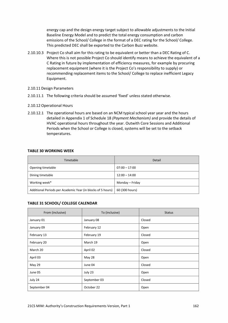
21CS MIM: Authority’s Construction Requirements Version, Part 1 162
energy cap and the design energy target subject to allowable adjustments to the Initial Baseline Energy Model and to predict the total energy consumption and carbon emissions of the School/ College in the format of a DEC rating for the School/ College. This predicted DEC shall be exported to the Carbon Buzz website.
2.10.10.3 Project Co shall aim for this rating to be equivalent or better than a DEC Rating of C. Where this is not possible Project Co should identify means to achieve the equivalent of a C Rating in future by implementation of efficiency measures, for example by procuring replacement equipment (where it is the Project Co’s responsibility to supply) or recommending replacement items to the School/ College to replace inefficient Legacy Equipment.
2.10.11 Design Parameters
2.10.11.1 The following criteria should be assumed ‘fixed’ unless stated otherwise.
2.10.12 Operational Hours
2.10.12.1 The operational hours are based on an NCM typical school year year and the hours detailed in Appendix 1 of Schedule 18 (Payment Mechanism) and provide the details of HVAC operational hours throughout the year. Outwith Core Sessions and Additional Periods when the School or College is closed, systems will be set to the setback temperatures.
TABLE 30 WORKING WEEK
Timetable Detail
Opening timetable 07:00 – 17:00
Dining timetable 12:00 – 14:00
Working week* Monday – Friday
Additional Periods per Academic Year (in blocks of 5 hours) 60 (300 hours)
TABLE 31 SCHOOL/ COLLEGE CALENDAR
From (inclusive) To (inclusive) Status
January 01 January 08 Closed
January 09 February 12 Open
February 13 February 19 Closed
February 20 March 19 Open
March 20 April 02 Closed
April 03 May 28 Open
May 29 June 04 Closed
June 05 July 23 Open
July 24 September 03 Closed
September 04 October 22 Open
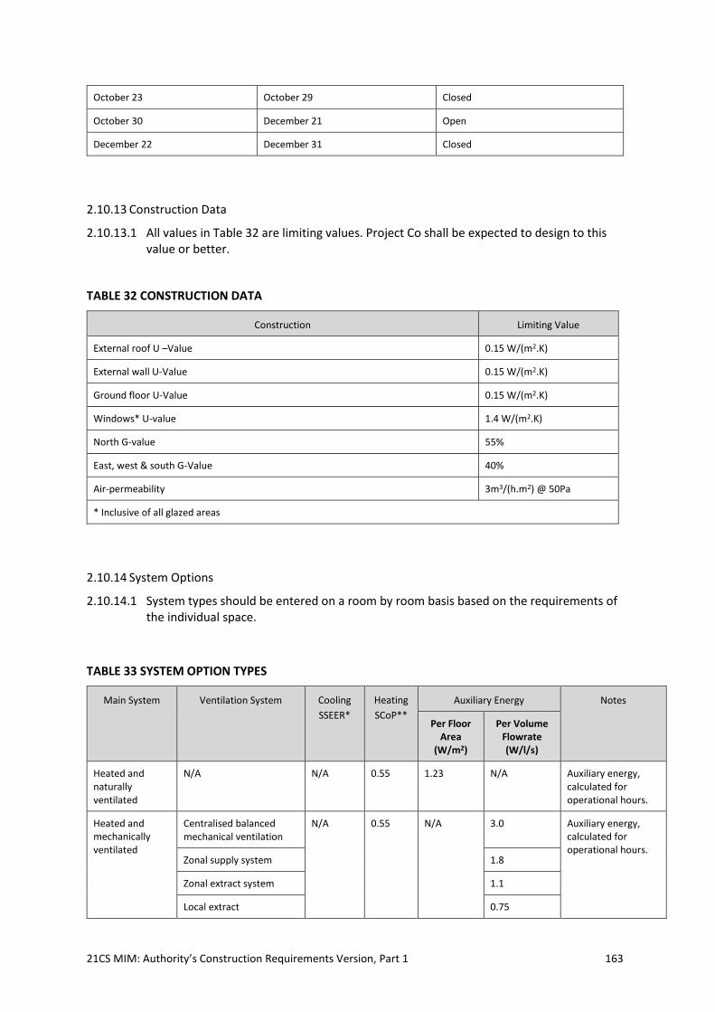
21CS MIM: Authority’s Construction Requirements Version, Part 1 163
October 23 October 29 Closed
October 30 December 21 Open
December 22 December 31 Closed
2.10.13 Construction Data
2.10.13.1 All values in Table 32 are limiting values. Project Co shall be expected to design to this value or better.
TABLE 32 CONSTRUCTION DATA
Construction Limiting Value
External roof U –Value 0.15 W/(m2.K)
External wall U-Value 0.15 W/(m2.K)
Ground floor U-Value 0.15 W/(m2.K)
Windows* U-value 1.4 W/(m2.K)
North G-value 55%
East, west & south G-Value 40%
Air-permeability 3m3/(h.m2) @ 50Pa
* Inclusive of all glazed areas
2.10.14 System Options
2.10.14.1 System types should be entered on a room by room basis based on the requirements of the individual space.
TABLE 33 SYSTEM OPTION TYPES
Main System Ventilation System Cooling
SSEER*
Heating
SCoP**
Auxiliary Energy Notes
Per Floor Area
(W/m2)
Per Volume Flowrate (W/l/s)
Heated and naturally ventilated
N/A N/A 0.55 1.23 N/A Auxiliary energy, calculated for operational hours.
Heated and mechanically ventilated
Centralised balanced mechanical ventilation
N/A 0.55 N/A 3.0 Auxiliary energy, calculated for operational hours.
Zonal supply system 1.8
Zonal extract system 1.1
Local extract 0.75
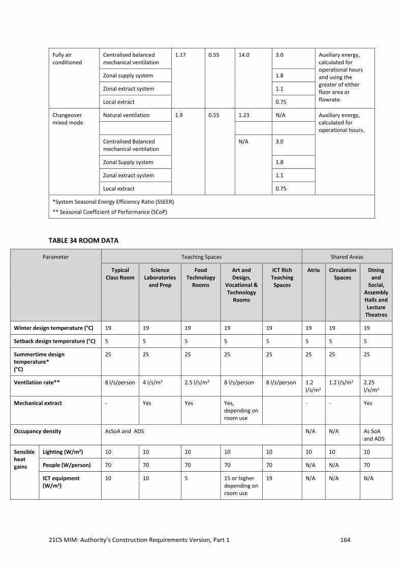
21CS MIM: Authority’s Construction Requirements Version, Part 1 164
Fully air conditioned
Centralised balanced mechanical ventilation
1.17 0.55 14.0 3.0 Auxiliary energy, calculated for operational hours and using the greater of either floor area or flowrate.
Zonal supply system 1.8
Zonal extract system 1.1
Local extract 0.75
Changeover mixed mode
Natural ventilation 1.9 0.55 1.23 N/A Auxiliary energy, calculated for operational hours.
Centralised Balanced mechanical ventilation
N/A 3.0
Zonal Supply system 1.8
Zonal extract system 1.1
Local extract 0.75
*System Seasonal Energy Efficiency Ratio (SSEER)
** Seasonal Coefficient of Performance (SCoP)
TABLE 34 ROOM DATA
Parameter Teaching Spaces Shared Areas
Typical Class Room
Science Laboratories
and Prep
Food Technology
Rooms
Art and Design,
Vocational & Technology
Rooms
ICT Rich Teaching Spaces
Atria Circulation Spaces
Dining and
Social, Assembly Halls and Lecture
Theatres
Winter design temperature (°C) 19 19 19 19 19 19 19 19
Setback design temperature (°C) 5 5 5 5 5 5 5 5
Summertime design temperature* (°C)
25 25 25 25 25 25 25 25
Ventilation rate** 8 l/s/person 4 l/s/m2 2.5 l/s/m2 8 l/s/person 8 l/s/person 1.2 l/s/m2
1.2 l/s/m2 2.25 l/s/m2
Mechanical extract - Yes Yes Yes, depending on room use
- - Yes
Occupancy density AsSoA and ADS N/A N/A As SoA and ADS
Sensible heat gains
Lighting (W/m2) 10 10 10 10 10 10 10 10
People (W/person) 70 70 70 70 70 N/A N/A 70
ICT equipment (W/m2)
10 10 5 15 or higher depending on room use
19 N/A N/A N/A
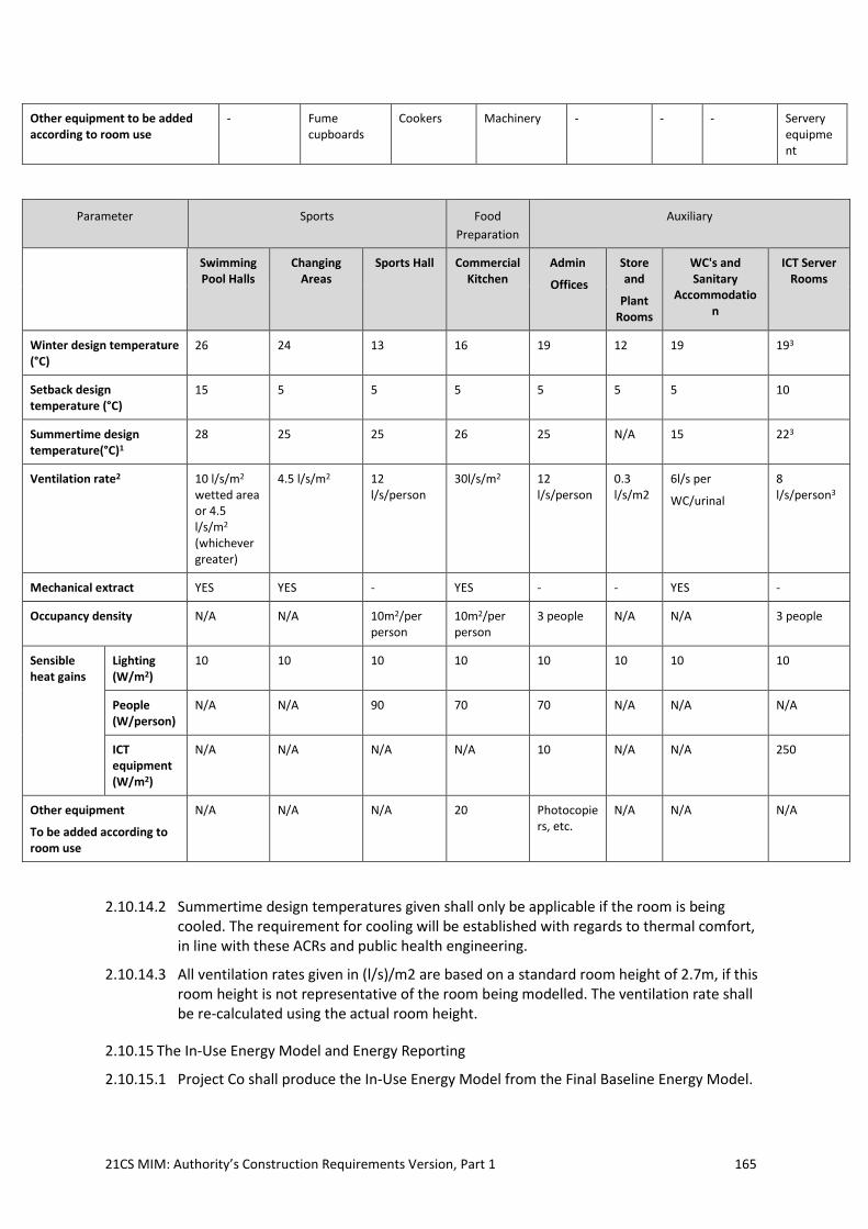
21CS MIM: Authority’s Construction Requirements Version, Part 1 165
Other equipment to be added according to room use
- Fume cupboards
Cookers Machinery - - - Servery equipment
Parameter Sports Food
Preparation
Auxiliary
Swimming Pool Halls
Changing Areas
Sports Hall Commercial Kitchen
Admin
Offices
Store and
Plant Rooms
WC's and Sanitary
Accommodation
ICT Server Rooms
Winter design temperature (°C)
26 24 13 16 19 12 19 193
Setback design temperature (°C)
15 5 5 5 5 5 5 10
Summertime design temperature(°C)1
28 25 25 26 25 N/A 15 223
Ventilation rate2 10 l/s/m2
wetted area or 4.5 l/s/m2
(whichever greater)
4.5 l/s/m2 12 l/s/person
30l/s/m2 12 l/s/person
0.3 l/s/m2
6l/s per
WC/urinal
8 l/s/person3
Mechanical extract YES YES - YES - - YES -
Occupancy density N/A N/A 10m2/per person
10m2/per person
3 people N/A N/A 3 people
Sensible heat gains
Lighting (W/m2)
10 10 10 10 10 10 10 10
People (W/person)
N/A N/A 90 70 70 N/A N/A N/A
ICT equipment (W/m2)
N/A N/A N/A N/A 10 N/A N/A 250
Other equipment
To be added according to room use
N/A N/A N/A 20 Photocopiers, etc.
N/A N/A N/A
2.10.14.2 Summertime design temperatures given shall only be applicable if the room is being cooled. The requirement for cooling will be established with regards to thermal comfort, in line with these ACRs and public health engineering.
2.10.14.3 All ventilation rates given in (l/s)/m2 are based on a standard room height of 2.7m, if this room height is not representative of the room being modelled. The ventilation rate shall be re-calculated using the actual room height.
2.10.15 The In-Use Energy Model and Energy Reporting
2.10.15.1 Project Co shall produce the In-Use Energy Model from the Final Baseline Energy Model.

21CS MIM: Authority’s Construction Requirements Version, Part 1 166
2.10.15.2 Project Co shall produce the Measurement and Verification Plan used to calibrate the Final Baseline Energy Model. This will include the metering strategy, the completed Automated Energy Data Collection Portal facilities and services spreadsheet, and the as built drawings showing all meters and connected loads.
2.10.15.3 Pre-Handover checks: Project Co shall ensure that the energy targets will be met from the first day of operation. A standard list of energy related items is to be prepared for the Independent tester to check30. There should also be an energy focussed section on the Snag list. The independent tester, in conjunction with the Commissioning manager, should in particular be checking that the BMS and EMS are correctly set up, that the core hours and term dates have been inserted properly, and that all metering systems are in place and functioning correctly.
2.10.15.4 For the first twelve (12) month period after the Actual Completion Date [in respect of the relevant Facility], Project Co will monitor energy consumption. After six (6) months Project Co will compare the actual energy consumption of the school/ college with the predicted energy consumption by the Final Baseline Energy Model on a system by system basis. If there is a significant discrepancy31, Project Co will determine the cause of the differences. At the end of the initial twelve (12) months, Project Co will again compare the actual energy consumption with that predicted by the Final Baseline Energy Model and demonstrate that the energy targets are being achieved.
2.10.15.5 In subsequent years, Project Co shall refine the In-Use Energy Model to achieve greater accuracy and better energy management and to reflect benchmarks and agreed energy reductions for example through invest to save measures for energy efficiency improvements.
2.10.15.6 Allowable adjustments that can be made to the Final Baseline Model, include: changes to Buildings, plant and equipment, weather, and hours of use. For example: excess lighting energy consumption due to operation of blinds, e.g. due to poor visibility of Legacy data projectors; requests from the school/ College to increase temperature set points above the normal maintained air temperatures given in these ACRs; and changes to equipment loads and length of the school day.
2.10.15.7 The predicted end use consumptions are compared with actual metered consumption figures and benchmarks or other school/ College end use benchmarks where possible to identify areas where energy is being wasted and to apportion payments in a fair and transparent way.
2.10.15.8 In order to claim weather adjustments, Project Co’s baseline projections for heating energy consumption must accurately reflect actual consumptions with a reasonable statistical confidence. . Project Co shall use IPMVP Volume I, Appendix B which summarizes basic uncertainty quantification techniques to guide decisions about the level of rigour suitable for each M&V process. Project Co shall also follow ASHRAE Guideline 14 on monitoring.32
2.10.15.9 The metering, monitoring and reporting of the data must be independent of the School/ College’s IT system.
30 and Schedules 10 and 13 of the Project Agreement should be updated accordingly 31 ie greater than 10%
32 The IPMVP and ASHRAE 14 are complementary documents that provide guidance and instruction to those interested in quantifying the results from energy savings projects.
21CS MIM: Authority’s Construction Requirements Version, Part 1 167
2.10.15.10 Project Co will provide a screen in a readily accessible location within the Facility which will continuously display the energy data from the EMS
2.10.16 Energy Payment Mechanism – Consumption Risk
2.10.16.1 Project Co shall take the volume risk on the actual consumption of the Building Load during Core Energy Hours Abuilding CEH to the extent that it is greater than Project Co’s predicted Target energy consumption for the Building Load during Core Energy Hours T
building CEH. Project Co’s predicted consumption T building CEH shall initially be based on the Final Baseline Energy Model and on the In-Use Energy Model once it has been agreed with the Authority, after allowable adjustments have been made, e.g., for weather or changes to Core Energy Hours.
2.10.17 Obligation to produce and agree the In-Use Energy Model
2.10.17.1 As soon as practicably possible following the Services Availability Date, but in any event by the end of the second (2nd) year following the Services Availability Date, Project Co shall use recorded data including actual metered energy consumption data to calibrate the In-Use Energy Model used to predict the Building Load during Core Energy Hours T
building CEH, which takes into account allowable adjustments. Calibration and allowable adjustments shall be in accordance with best practice for measuring and reporting on energy and water consumption based on actual weather patterns, the hours that the Facility is open and examples set out in these ACRs. Adjustments to the In-Use Model that affect the Building Load T building CEH during Cre Energy Hours must be agreed with the Authority as they will form the basis of energy payments throughout the Contract Period.
2.10.17.2 Project Co’s Initial Energy Model prediction of the Target Building Load during Core Energy Hours T building CEH must be less than of 38 KWhe for both Primary and Secondary Schools and 70 KWe for Colleges without pools as in [3.5] of Section 7 (Utilities Management) of Schedule 14 (Payment Mechanism) of this Agreement.
2.10.17.3 Where kWhe is the equivalent electrical kWh calculated by multiplying the different fuel kWh consumptions for different energy sources by the following standard energy weighting factors:
TABLE 35 STANDARD ENERGY WEIGHTING FACTORS
Category Description Energy
Weighting
Factor
Electricity includes mains electricity, electricity from combined heat and power and renewable energy
1.0
All Fuels includes, gas, oil, and biofuels 0.4
Thermal Energy includes geothermal, district heat and heat from combined heat and power and solar thermal
0.5
2.10.17.4 At a School or College in which the Core Sessions commence at 07:00 the Core Energy Hours are
all School/ College Day Mornings and all School/ College Day Afternoons on School/
College Days only; and
the hours of 12:00 a.m. midnight to 07:00 a.m. every day of the year.
21CS MIM: Authority’s Construction Requirements Version, Part 1 168
2.10.17.5 The School Day Core Energy Hours shall be 07:00 to 17:00 for 195 days for the initial design and as subsequently agreed with the School/Authority. At a School/ College in which the Core Sessions commence at a different time, the timings given in this paragraph will be adjusted forwards or backwards by the same amount as the commencement time.
2.10.17.6 Project Co will share the risk with the Authority on the volume exceeding Project Co’s predicted Target Building Load consumption T building, CEH, of 38 kWhe (70 kWhe for Colleges) and take 100% of the risk on the volume exceeding the energy cap C building, CEH of 46 kWhe for a Primary or Secondary School (85kWe for Colleges). with no pool before adjustments after allowable adjustments have been made and will pay for the extra energy consumed in accordance with [Section 8] of the Payment Mechanism.
2.10.17.7 At the annual review meeting the Authority and Project Co should agree that the In-Use Energy Model end use systems targets are achievable and realistic for the school/ Colleges’ operation. During the meeting, Project Co shall document, so that the Authority can understand, the discrepancies, if any, between the Final Baseline Energy Model, the In-Use Energy Model, an Automated Energy Data Collection Portal benchmarks and the actual energy consumption figures of the School/College so that the energy consumption may be improved the following year as incorporated into the Energy and Utilities Management Plan. Project Co shall report annually to the Authority on the total fuel consumption figures. At the annual review meeting Project Co shall report on the actual energy consumption figures as compared with the target predicted consumption figures in accordance with [Section 8] of the Payment Mechanism.
2.10.17.8 Where Project Co and the Authority cannot agree Project Co’s proposed adjustments to produce the Target Building Load during Core Energy Hours, Tbuilding,CEH that determines the Energy Payments, the Authority will employ a suitably qualified independent third party energy assessor, to be agreed with Project Co, to review the Project Co’s proposals, the Automated Energy Data Collection Portal benchmarks and the energy and weather data to determine payments. The International Performance and Measurement Protocol (IPMVP) and ASHRAE Guideline 1433 will be used to resolve any disputes about adjustments to energy payments. Project Co shall subject to clause 57 (Dispute Resolution Procedure) of this Agreement be bound by the findings of such independent third party. Project Co shall upon written request permit the Authority and/or such independent third party energy assessor to inspect any part of the Buildings and/or access to all the Project Co 's records, receipts, invoices, reports, drawings, technical specifications and performance logs relating to the Building Load Ebuilding energy consumption figures, so as to enable the Authority and/or such independent third party energy assessor to obtain an accurate assessment of any of the figures quoted. Project Co shall provide all reasonable co-operation and assistance to the Authority and any
33 See the International Performance and Measurement Protocol (IPMVP) published by the Efficiency Valuation Organization and freely available from www.evo-world.org. Volume I, 2012 Edition describes the methodology and Volume III Part I gives examples of some current applications of IPMVP to new build construction projects. IPMVP is a framework of definitions and broad approaches whereas ASHRAE Guideline 14 provides detail on implementing M&V plans with the framework. IPMVP makes a provision for limited metering under Option A whereas ASHRAE requires metering for all options. IPMVP's discussions on balancing of Uncertainty and Cost (Volume 1 Chapter 4.11) are enhanced by ASHRAE's definition of ways to quantify uncertainty so that M&V design decisions can consider costs in light of the best available methods for quantifying uncertainty.
21CS MIM: Authority’s Construction Requirements Version, Part 1 169
independent third party energy assessor and shall allow them access to such documents and information and shall in a bona fide manner respond promptly to all reasonable requests for further documents and information made by the Authority and/or any independent third party energy assessor in respect of the Building Load Ebuilding energy consumption figures, the Project Co’s proposals and the projected Energy Payments.
2.10.17.9 The Target Building Load, Tbuilding CEH on which Project Co and the Authority shall share the volume risk during Core Energy Hours comprises:
Space Heating - The temperatures to be used for predicting the initial baseline heating
consumption are the normal maintained air temperatures given in Table 27. The
minimum room temperature in any serviced area shall be 5oC at which temperature the
heating system will be automatically switched on for a minimum of thirty (30) minutes
for frost protection. Adjustments can be made where the School/ College chooses to run
parts of the building at higher temperatures. This energy end use shall be separately
metered;
Internal lighting and emergency lighting excluding external lighting - This energy end
use shall be separately metered. Hours of use are those in the input parameter data set
for the type of school/ College but can be adjusted for actual hours of use where the
School/ College chooses to use the lighting out of hours, for example, they may leave all
the corridor lights on all night for security purposes;
[Swimming Pool heating - including pump and water treatment, and pool related
ventilation and air conditioning loads; and]
Building related services: including protection systems, fire alarms, sprinkler systems
and intruder alarms – lifts - ventilation plant including that serving changing rooms,
toilets and Kitchen, boiler plant and pumps and other plant and any air conditioning
loads, i.e. to server room or teaching areas. – Project Co shall meter the total electrical
load/s for these energy end uses.
2.10.17.10 The End User Loads, which are not counted as part of the Building Load for the purposes of the Payment Mechanism are:
External sports and flood lighting – This energy end use shall be separately metered;
External security and amenity lighting – This energy end use shall be separately
metered;
Hot water consumption – The domestic hot water loads shall be metered;
catering gas, electricity and water consumptions – These end uses shall be separately
metered;
Server and hub room loads including all ICT equipment but excluding internal lighting
and heating, ventilation and any air conditioning equipment required to achieve the
conditions specified in Table 27. Electrical loads to server rooms shall be separately
metered; and
Miscellaneous power loads - including local extract ventilation such as dust and fume
extract (including fume cupboards), ICT equipment outside server rooms and power and
equipment loads such as hand driers, kilns, and theatre lighting including small power,
Legacy Equipment and equipment provided by Project Co.
2.10.17.11 The Authority is permitted to bring additional power consuming equipment into the Facility. The changes must be notified to Project Co who may need to adjust the In-Use Energy Model end uses accordingly.
2.10.17.12 Project Co and the Authority shall work together to achieve:
21CS MIM: Authority’s Construction Requirements Version, Part 1 170
an Initial Baseline Energy Model design target in electricity equivalent kilowatt hours,
KWhe for TbuildingCEH + Hot Water consumption + Small Power Consumption during Core
Energy Hours of less than the following figures depending on the type of Facility;
Secondary School with no pool 66 KWhe;
Primary School with no pool 52 KWhe; and
Colleges with no pool 108kWe
a carbon rating for the [relevant] Facility’s total energy consumption equivalent to a DEC
rating of C.
2.10.17.13 Project Co and the Authority shall also work together to limit all energy end uses to best practice benchmarks. These benchmarks for large (>10,000m2) Secondary Schools and are currently:
a. lighting 12 kWh/m2/annum;
b. external Lighting 2 -12 kWh/m2/annum;
c. heating 34.5 kWh/m2/annum;
d. hot water 9 kWh/m2/annum;
e. fans and pumps (depends massively on extent of HVAC, figures normalised across school/
College total floor area, however range is) 6-15 kWh/m2;
f. server rooms 8 kWh/m2;
g. lifts 1 kWh/m2;
h. IT circa 8-10 kWh/m2 (although depends on pupil to PC/laptop ratio and charging method)
i. miscellaneous and small power 5-10 kWh/m2;
j. catering 7-14kWh/m2; and
k. current K2energy/iSERVcmb or similar industry benchmarks for the various energy end uses
should be used, where available.
2.10.17.14 Project Co and the Authority shall also work together to limit all energy end uses to best practice benchmarks. These benchmarks for large (>10,000m2) Colleges and are currently:
l. lighting 15- 30 kWh/m2/annum;
m. external Lighting 2 -12 kWh/m2/annum;
n. heating 45 kWh/m2/annum;
o. hot water 13 kWh/m2/annum;
p. fans and pumps (depends massively on extent of HVAC, figures normalised across school/
College total floor area, however range is) 6-16 kWh/m2;
q. server rooms 8 kWh/m2;
r. lifts 3 kWh/m2;
s. IT circa 8-10 kWh/m2 (although depends on pupil to PC/laptop ratio and charging method)
t. miscellaneous and small power 15-30 kWh/m2;
u. catering 7-14kWh/m2; and
v. current K2energy/iSERVcmb or similar industry benchmarks for the various energy end uses
should be used, where available.
2.10.18 Project Co predicted loads
21CS MIM: Authority’s Construction Requirements Version, Part 1 171
2.10.18.1 Project Co shall predict the annual energy and utilities consumptions of the following Service Infrastructure and report on them annually in accordance with the Energy and Water Efficiency Plan. ProjectCo shall report on the:
a. Building Load end uses identified in these ACRs;
b. end user load end uses identified in these ACRs;
c. total hot and cold-water consumption; and
d. catering hot and cold-water consumption.
2.10.18.2 The energy and water consumption of legacy Facilities and Buildings or parts of Buildings which may be let out to the community on a commercial basis, may be used out of the Core Days for community use such as sports or leisure facilities and shall be separately accounted for in energy and water prediction calculations and may be separately zoned and metered
2.10.19 Energy and Utilities Monitoring and Reporting
2.10.19.1 Metering and sub meters shall be provided as described below.
2.10.19.2 Project Co shall ensure that Building Services systems are effectively zoned to reflect the operational use of the different areas of the Facility development to ensure effective control and in order to minimise energy consumption.
2.10.19.3 Project Co will provide an EMS which will automatically collect, store energy data, room temperature, CO2 data as well as data from the site weather station. This is to be capable of transmitting the data offsite independently of the school/ College’s IT system.
2.10.19.4 The monitoring will be able to display energy consumption on a system by system basis, separated out into individual floors, intuitively labelled so that the area and system can easily be identified. This will used as a diagnostic tool and will use a data collection platform to display the energy consumption.
2.10.19.5 Project Co shall use the Automated Energy Data Collection Portal, to monitor and report on the Facility’s energy, water, CO2 and temperature, via the buildings EMS. Project Co shall train the Facility’s Premises Team how to use the EMS and the Automated Energy Data Collection Portal monitoring system as part of the building performance evaluation and Soft Landings phases, taking account of any requirements in these ACRs about the way in which the training is delivered.
2.10.19.6 The Automated Energy Data Collection Portal must comprise an automated cloud based data collection and management system, either as part of or separate from the BMS/EMS, but intrinsically linked to it for information and data collection purposes. It must be able to gather the following information from the BMS/EMS:
a. all meter and sub-meter readings (1/2 hourly collection)
b. all external and internal space (room) temperature sensor logs (1/2
hourly collection)
c. all internal space (room) CO2 sensor logs (1/2 hourly collection)
d. all corresponding building/service/zone timeclock start and end periods
e. LTHW system all flow and return temperature sensor logs (1/2 hourly
collections)
f. DHWS system all temperature sensor logs (1/2 hourly collections)
g. any other sensor log relevant to energy use (1/2 hourly collections)
21CS MIM: Authority’s Construction Requirements Version, Part 1 172
All data collection should be in an industry standard .xls file format. It must be able to provide automated reports (at least monthly) with easy to understand graphical reporting and KPI’s to enable the layperson end user to easy review, understand, and digest appropriate building energy performance data for the entire Facility;
2.10.19.7 In addition to the data collection platform, a simple energy display app will be provided for the school/ college to use to access headline environmental and energy parameters. It will use MQTT or similar application, to access the parameters for display on phone or tablet devices.
2.10.19.8 Following the Actual Completion Date, the Project Co shall monitor the energy use against the installed meters and will provide the Authority via the Automated Energy Data Collection Portal with on line data and benchmark information on at least a monthly basis and a daily basis when required by the Authority, by means of data exchange with the Automated Energy Data Collection Portal .
2.10.19.9 The Automated Energy Data Collection Portal reports should be used to provide the feedback interface for the Facility Users by means of the monthly reporting templates. Providing these monthly reports to the Authority will enable them to provide appropriate control over those energy consumers which they influence, helping the overall School/ College energy targets to be achieved. Alternatively, with the Authority’s approval, Project Co can choose to use other energy management reporting software to produce similar feedback reports for the School or College.
2.10.19.10 ProjectCo shall also commence reporting to the Authority on energy use from the Actual Completion Date using the Monthly Energy Report and Energy Report required under Schedule 14 (Payment Mechanism) of this Agreement. The Monthly Energy Report will be set out to report progress monthly against a designated end of year month. This enables progress against contractual targets to be assessed as part of BPE, and early corrective action to be taken if needed.
2.10.19.11 To enable the Authority to participate in benchmarking the data from each Facility shall be submitted to the Automated Energy Data Collection Portal by Project Co in a compatible format. Project Co shall also fully describe each Facility with the data requested by the Automated Energy Data Collection Portal.
2.10.19.12 The operational data required for the meters and sensors described in the asset spreadsheet shall be automatically exported via the Buildings EMS system to the Automated Energy Data Collection Portal , to enable inclusion in the automated reports which will be sent to Project Co and the Authority (and each School Entity in the case of a School(s) Project). Accessing this data must be independent of the Building’s own ICT system. Manual transmission of the data will not be acceptable.
2.10.19.13 The minimum level of sensor data required is space temperature, carbon dioxide and lux sensor data for each heating zone (in an occupied space, not circulation), and data from an outside weather station. This allows energy performance and building systems performance to be evaluated. Project Co may choose to include additional sensor data, e.g. room temperature and CO2 sensor data for each room, in order that further insights into the effectiveness of the Building Services HVAC systems can be provided to the Authority and Project Co. The Automated Energy Data Collection Portal shall be capable of assessing energy use per space by these appropriate sensors being in place.
2.10.19.14 Correlating the internal conditions with energy consumption enables the identification of avoidable energy use, building performance issues and sensors or meters that are likely to be out of calibration. This is a powerful means of remote system diagnosis. Project Co
21CS MIM: Authority’s Construction Requirements Version, Part 1 173
can use this data to aid seasonal commissioning adjustments during the 12-months following the Actual Completion Date and thereafter as required.
2.10.19.15 Project Co shall provide monthly exception reporting to identify and isolate incidences of avoidable utilities consumption regardless of who is responsible for the cost of utilities. Project Co shall identify instances where consumption exceeds the predicted end use or established benchmarks, e.g., by more than 15% and additional utilities payments are likely to be incurred. Examples would be if Project Co noticed that: all lights in corridors are left on all night; loads are left on during holiday periods, or there is high consumption overnight or during holiday periods.
2.10.19.16 The actual against anticipated use and previous years’ data when available will be reported quarterly by Project Co.
2.10.19.17 At the end of each Contract Year the actual energy end use consumption figures shall be compared with the predictions from the In-Use Energy Model and the Automated Energy
Data Collection Portal benchmarks for other Facilities.
2.10.19.18 Project Co shall provide the Authority and their agents with full access with unrestricted use of and rights to energy, heating, hot water, lighting and water consumption metering data. At least the last three years' historic data shall be available in a suitable on-line format designed to be understood by Students and school/ College staff. Project Co shall agree with the Authority the level and type of real time data, including weather data, to be provided for Curriculum use.
2.10.19.19 Energy and utility use data shall be acquired and stored on the local EMS every thirty (30) minutes. The data shall be uploaded at least every month, and preferably every day, to the Automated Energy Data Collection Portal for energy management purposes.
2.10.19.20 Project Co shall ensure that Facilities are metered separately for all utilities in line with Approved Document L (AD L) in support of the Building Regulations and CIBSE TM39. Automatic Meter Readings (AMR) must be provided on all incoming Service Installations and sub-metering to report energy end use consumptions.
2.10.19.21 Project Co shall ensure that the energy use data has separate data streams (usually meters) for all the meters identified above and for each of the following HVAC components that are installed:
2.10.19.22 Fixed Building Services Meters:
a. boiler energy use (electrical and fossil fuel separated);
b. hot water pumps;
c. domestic hot water pumps and temperature maintenance tapes;
d. any separate heat rejection fans;
e. individual air handling units (if applicable);
f. cooling Systems: e.g., packaged a/c systems and split systems (if applicable);
g. heat pumps; (if applicable);
h. lighting Distribution Boards; and
i. motor Control Panels.
2.10.19.23 Additional Meters:
domestic Hot water supplies;
cold water consumption; and
small Power Distribution Boards.
21CS MIM: Authority’s Construction Requirements Version, Part 1 174
2.10.19.24 Specialist Meters:
catering facilities (Gas, domestic hot water, and electricity);
server Room equipment, including UPS;
external lighting;
multi-surface sports facilities and external sports lighting; and
swimming pools (process and lighting loads)
2.10.19.25 Theoretical corrections to end use consumptions where individual metering of that end use is required will not be permitted.
2.10.19.26 The data is usually provided by meters but many HVAC components, e.g., pumps are now fitted with in-built sensors and meters which can be connected to the internet and data collected from them directly. Use of in-built meters will be acceptable to the Authority where they meet the requirements detailed in these Authority’s Construction Requirements for meters. Duplicate metering and data collection systems should be avoided where the components can already provide the required data.
2.10.19.27 Project Co shall ensure that data from the AMR system and headline output data from the Building Controls and Energy Management Systems in respect of each Facility, for example room temperatures and heating and hot water flow/return temperatures, is uploaded to the Automated Energy Data Collection Portal and available to the Authority (and the relevant School Entity in the case of a School(s) project) via the web for use in energy management and monitoring energy performance and consumption.
2.10.19.28 The Authority will have responsibility for day to day energy management at the Facility and Project Co will have overall responsibility for energy monitoring at the Facility and shall report findings to the Authority. Project Co and the Authority shall work together to overcome any inefficiencies in system operation identified by the Project Co or the Authority.
2.10.19.29 The Authority may appoint a person with overall responsibility for energy management at theFacility. This person shall report his findings to the Authority and Project Co. Project Co and the Authority shall work together to overcome any inefficiencies in system operation identified by the relevant person responsible for energy management.
2.10.19.30 Renewable energy contracts, payments and incentives must be agreed by the Authority.
2.10.19.31 The energy consumption in run and standby conditions for all equipment shall be estimated by Project Co for the purposes of calculation of energy end use loads. For this purpose, Project Co shall obtain information on Legacy Equipment, including name plate loads, manufacturer’s names and serial numbers and shall provide the information to the Authority.
2.10.19.32 Project Co may meter any item of equipment where they would like to determine the actual energy or water use.
2.10.19.33 Project Co shall monitor the individual energy end uses. Project Co shall produce a metering schematic and upload the data to the Automated Energy Data Collection Portal . This will be fully completed by the commencement of the Operational Term. End use data and meter readings will subsequently be uploaded to the Automated Energy Data
Collection Portal continuous monitoring and benchmarking website. Project Co shall provide commissioning records for the metering and monitoring system including test data uploads and reports from the Automated Energy Data Collection Portal database. Project Co shall provide as built meter schematic record drawings showing all the meters and the loads connected to each meter.
21CS MIM: Authority’s Construction Requirements Version, Part 1 175
2.10.19.34 Annually, the Contractor shall report actual consumption figures and DEC ratings on the Carbon Buzz and iSERVcmb websites or similar on-line systems approved by the Authority in order to benchmark the Facility’s energy profile.
2.10.20 Weather data
2.10.20.1 Project Co shall:
provide and monitor a weather station at the [/each] Facility that will be in a location
regarded as suitable for collecting weather data; and
where available may reference local Met Office data.
2.10.20.2 Project Co shall specify the type and location of weather station to be used.
2.10.20.3 Project Co shall use the weather data:
to calibrate the Final Baseline Energy Model after the first year of operation;
to make adjustments to energy consumption figures for comparison with the In-Use
Energy Model;
to record and report weather variations; and
to provide to parties, that require this information, as part of a dispute resolution
regarding adjustments to the Building Load, Ebuilding.
2.10.20.4 As a minimum the following weather data is required; Outdoor Dry Bulb Temperature, Outdoor Humidity, Wind Speed, Wind Direction, Dew Point and Solar Radiation over a maximum of 1-hour averages.
2.10.20.5 The weather data shall be available for Curriculum use by the Authority [and the School Entitiy].
2.11 Building Services
2.11.1.1 Project Co shall ensure that the design of Building Services meets the requirements within this section.
2.11.1.2 Project Co shall ensure that the Building Services are designed to comply with Law and best practice guidance.34 Project Co shall ensure that they:
are designed and installed to be effective, safe, clean and hygienic for all users;
are easy to use and avoid complex systems that require specialist maintenance;
are energy efficient in line with current best practice; and
are zoned in accordance with these ACRs.
2.11.1.3 Project Co shall ensure that the use of passive measures are considered before active measures are proposed as part of the integrated building design.
2.11.1.4 Project Co shall ensure that the requirements listed above are in the Environmental Strategy Report included in Project Co’s proposals in Schedule 6 Part 4.
2.11.1.5 Project Co shall ensure that the distribution of Service Infrastructure throughout provides flexibility for future refurbishment, expansion and renovation. The Service Infrastructure distribution shall allow ease of access for maintenance but should also be concealed
34 In particular CIBSE and DfE and the Worcestershire County Council Trade Preambles for mechanical and electrical Service Infrastructure which provide a source of good practice guidance for installations in Schools and other public buildings.
21CS MIM: Authority’s Construction Requirements Version, Part 1 176
throughout, where possible, to enhance the aesthetics of the Facility and to reduce the risk of personal injury, Malicious Damage and harm.
2.11.1.6 Project Co shall ensure that the Building Services engineering design and installation:
takes account of the requirements of the end Facility Users and occupants,
including those with SEN (D);
is robust and fit for purpose; and
is tamper-proof and not easily vandalised or adjusted to the detriment of the
system, users or Building itself.
2.11.1.7 Any utility services shall follow Good Industry Practice and be compliant with all relevant Law including the ‘Environmental Protection Act 1990’.
2.11.1.8 Project Co shall notify the relevant authority in accordance with Law, obtain any required approvals for the installation and negotiate new provisions where required to meet these ACRs.
2.11.1.9 Project Co shall comply with utility company infrastructure work requirements, undertaking any necessary reinstatement, protection or diversions of existing Service Infrastructure within the Site[s] with minimal disruption to Service Infrastructure and surrounding public and Facility activities.
2.11.1.10 Project Co shall ensure that any incoming utility supplies run within the Site boundary and are routed in accessible locations throughout the Site. Project Co shall install the incoming Service Infrastructure from the Site boundary to the Facility Building to follow roadways, paths etc. Project Co shall avoid routing of incoming Service Infrastructure across sports fields.
2.11.1.11 Project Co shall locate any electrical substations and gas meter houses on the Site boundary in an accessible, unobtrusive and convenient location to allow for out of hours access by the relevant Service Provider. Project Co shall liaise with the relevant Service Providor to ensure that the locations and design of the substations and gas meter housings are in line with the relevant Service Providor's specific requirements.
2.11.1.12 Project Co shall ensure that the following requirements are met:
Service Infrastructure is to be located and routed in order to provide flexibility and
choice for room layout;
pipe work, cables and equipment are easily accessible for maintenance, while
allowing that in Specially Resourced Provision and Designated Units services
may need to be concealed;
all connections, distribution systems, components and containment systems are
safely protected, tamper-proof, correctly insulated, free from exposed contacts
and clearly labelled;
all visible pipe work and cable containment finishes are complete, clean and
hygienic;
all plant, machinery and switchgear is guarded and locked where appropriate;
locks and interlocks are fitted as required by the appropriate statutory bodies;
the integrity of fire breaks within ceiling and roof voids cannot be breached by the
installation of Service Infrastructure; and
Service Infrastructure default is set to ‘off’.
2.11.2 Boiler plant
21CS MIM: Authority’s Construction Requirements Version, Part 1 177
2.11.2.1 Project Co shall ensure that:
all boiler loads are based on the results of an hourly heat demand model for the
Building35.;
all tanks are designed for future use with bio-fuel;
all burners are commissioned by an engineer employed by the burner or boiler
manufacturer;
carbon monoxide (CO) detection equipment interlocked with safety shut-off
valves is installed in all boiler rooms;
all chimney flue systems except those serving direct gas fired boilers operate
under negative pressure without flue fans;
there is an adequate gas supply available for the proposed installation. Project Co
shall be responsible for all aspects of liaising with the relevant Service Provider to
provide the necessary gas connection. The gas supply shall be without the use of
gas boosters wherever possible;
boilers are provided to give a margin to allow for maintenance; to be sized as 2
boilers at 66%; or 3 at 40%; or modular boilers sized so that N boilers provide
100% capacity and N+1 are installed;
the burner control is modulating type in accordance with AD L and that the boilers
are controlled to optimise the efficiency of the system;
direct ‘Weather compensation’ is used to vary the boiler flow rate and leaving
water temperature according to the outdoor air temperature to maximise energy
saving (constant temperature boiler operation with downstream mixing valves is
not allowable for gas fired condensing boilers, only allowable for higher
temperature heat sources such as biomass boilers or CHP engines);
condensing boilers make full use of the condensing mode of the boilers during
part load conditions, i.e., the boilers operate with a design return temperature of
no higher than 50ºC at peak full load operation and have a weather compensation
schedule (as item c. above) to reduce the return water temperature to 20ºC at
mid-season part loads; and
the boilers have maximum NOx emissions of 40 mg/kWh unless otherwise stated
in the planning application or other relevant standards documents.
2.11.2.2 Project Co shall ensure that there is an appropriate flue provision for any boiler installation that is manufactured by a Member of the British Flue and Chimney Manufacturers Association (BFCMA). The flue shall be twin walled and insulated. The flue system shall be designed to manufacturer’s recommendations and comply with the requirements of The Clean Air Act 1956 and the local planning authority.
2.11.2.3 Project Co shall ensure that any boilers provided are located in a dedicated main plant room or purpose formed boiler room. The Plant Area shall be naturally ventilated, including the air required for combustion purposes, via louvres and/or louvered doors. The ventilation shall comply with the requirements of currentBuilding Regulations, IGEM standards, Welsh and British Standards and UKLPG recommendations. Permanent ventilation openings at high and low level will be provided to the external wall of the boiler plant room as necessary to comply with IGEM/UP/10 and BS 6644.
35 An example is the heat demand model used in the carbon trust biomass boiler sizing tool.
21CS MIM: Authority’s Construction Requirements Version, Part 1 178
2.11.2.4 Welsh and British Standards and UKLPG recommendations. Permanent ventilation openings at high and low level will be provided to the external wall of the boiler plant room as necessary to comply with IGEM/UP/10 and BS 6644.
2.11.3 Commissioning/Acceptance/Annual Tests for boiler/flue systems
2.11.3.1 For all boiler plant and direct-fired hot water generators of output greater than 4kW, Project Co shall carry out commissioning and annual performance tests for emissions and combustion efficiency and record the results in a logbook. Tests shall be in accordance with professional-level guidance such as that published by the Carbon Trust and the Chartered Institution of Building Services Engineers (CIBSE).
2.11.3.2 Project Co shall ensure that the boiler/flue system is tested during commissioning once the boiler can be brought up to full fire for a sustained period as follows:
by flue gas analysis with an EN 50379:236 compliant instrument;
at full fire and at low fire;
for O2, CO, CO2, HC measured in mg/m³;
to record the temperature of the incoming combustion air and of the flue gases;
for pressure differential to verify the performance of the flue. The flue system is
tested to ensure that its leakage rate does not exceed that designated according
to EN144337 for the particular flue type; and
the flue gas loss % (i.e. - % energy loss up flue [Siegert Formula]), lambda (the
degree to which the fuel air mix approaches the ideal), boiler efficiency and dew
point shall be recorded.
2.11.3.3 Where there is no permanent monitoring of flue gas analysis, flue gas temperature, mass flow, flue gas velocity and draft there is an opening with readily removed, gas-tight cap into the side of the primary connecting flue of 12 – 22mm for a Flue Gas Analysis probe. This is within 500mm of the boiler connection or according to the boiler manufacturer’s instruction and upstream of any draft stabiliser or anything which might alter the temperature or composition of the flue gas.
2.11.4 Annual monitoring
2.11.4.1 Project Co shall design the system to enable annual repetition of the above test to provide an independent check on the system’s efficiency and its emissions (as required by the Service Level Specification).
2.11.5 Biomass and biofuel systems
2.11.5.1 Biomass boilers should only be used with the explicit written permission of the Authority, and dependent upon a detailed business case being provided to demonstrate how a biomass boiler would represent best value for the Facility in terms of energy reduction and whole life operational costs.
2.11.5.2 Project Co shall assess the feasibility of using any biomass boiler systems using the Carbon Trust Biomass Boiler sizing tool. The tool should be used to prove that the heating system balance temperature, the utilisation factors for the boilers, the sizes of buffer vessels and/or thermal stores and the seasonal heating system efficiency justify the use
36 BS EN 50379.2
37EN 1443 Flue leakage
21CS MIM: Authority’s Construction Requirements Version, Part 1 179
of biomass as a fuel and justify the key parameters of the system design. Account shall be taken of Law and design advice38.
2.11.5.3 For biomass and biofuel systems to function efficiently, a reliable and consistent supply of quality-controlled fuel is required39. Project Co is expected to demonstrate that local sources of suitable such fuel are readily available from a minimum of three (3) independent sources or providers to ensure competitive fuel supply and delivery costs.
2.11.5.4 The feasibility assessment and planned fuel supply shall be recorded in heating strategy in the[ ] Environmental Strategy Report included in the Project Co’s Proposals in Schedule 6 Part 4.
2.11.5.5 Project Co shall complete the design and installation of biomass boiler systems to all relevant current standards and regulations including CIBSE AM15 - Biomass Heating Application Manual, 2014.
2.11.5.6 Project Co shall provide biomass boiler units installed in line with the manufacturer’s requirements.
2.11.5.7 Project Co shall ensure safe, suitable and efficient fuel storage and delivery and ash handling is in place to accommodate the biomass installation.
2.11.5.8 Where biomass is proposed, the day-to-day management of this installation must be fully discussed and agreed with the Authority.
2.11.6 Water supplies
2.11.6.1 Project Co shall design, supply, install, test and commission a potable/non-potable cold-water service system capable of providing an adequate supply of potable and/or non-potable water to draw off points throughout the Building.
2.11.6.2 The system will be designed to the following parameters:
maximum velocity of water in pipework - 2 m/sec; and
maximum water temperature in accordance with L8
2.11.6.3 Project Co shall design and install public health Engineering Services in accordance with these ACRs and public health engineering. Drinking water facilities and hot and cold-water supplies shall comply with the School Premises Regulations 1999.
2.11.6.4 Project Co shall comply with the School Premises Regulations for drinking water facilities and for hot and cold-water supplies.
2.11.7 Drinking water
2.11.7.1 Project Co shall design and install any domestic water services systems provided to serve the Works to be:
a. sufficient to accommodate the proposed level of occupancy and in line with all
relevant standards and statutory requirements;
b. robust and fit for purpose;
c. not routed such that the location of pipework and connections impact on the learning
environment within the Facility;
38 Guidance on what load is suitable to be met with which type of biomass system, burning which fuel and on system design is available from CIBSE and the Carbon Trust.
39 BS EN 15234-1:2011 Solid biofuels. Fuel quality assurance. General requirements.
21CS MIM: Authority’s Construction Requirements Version, Part 1 180
d. designed and installed to be safe, clean and hygienic for all Facility Users; and
e. designed and installed such that they minimise unnecessary water usage.
2.11.7.2 Project Co shall ensure that wholesome supplies of fresh palatable drinking water are provided around the Facility, both internally and externally, and that these outlets:
are adequate for the number of Student places;
may be taps over Classroom sinks, fountains or bottle fillers;
are located in line with the relevant Site Specific Brief;
are positioned to be easily accessible by all Students at all times, but physically
separate from toilets and hand washing areas;
are clearly and correctly marked as drinking water;
shall have appropriate drainage facilities and be sufficiently robust to deter casual
vandalism; and
shall be provided in every Dining and Social area.
2.11.7.3 Project Co shall ensure that, due to the difficulties of meeting all the conditions for water quality, wherever possible drinking water supplies in Facilities shall be connected directly to the cold water main and that water supplies fed from storage tanks not designed for potable water provision shall be clearly labelled as “not drinking water”.
2.11.7.4 Project Co shall ensure that:
a. drinking water outlets and fountains should be located to avoid misuse, spillages and
waste;
b. drinking water installations should be designed to permit Facility Users to recharge
water bottles using spigots and the supply system should incorporate a ‘dead’ handle
system to minimise spillages and prevent the water supply being left on;
c. drinking fountains must have appropriate drainage facilities and be sufficiently robust
to deter casual vandalism;
d. details of drinking water provision are included in the water efficiency plan as part of
the Environmental Strategy Report in Project Co’s Proposals in Schedule 6 Part 4;
e. in Secondary Schools and Colleges, a drinking water fountain shall be provided on
each floor of each Building, with one drinking water fountain serving a maximum floor
area of 1000m2;
f. in Primary Schools, drinking water shall be supplied to all Classroom sinks via a
labelled tap. In any Suite of Spaces where there are no Classroom sinks, drinking
water fountains shall be provided that are easily accessible to all Students in that
suite; and
g. a drinking water fountain shall be provided in an inside area easily accessible from
external areas used for play and sport.
2.11.8 Rainwater for use (Rainwater Harvesting)
2.11.8.1 Rainwater for use, or rainwater harvesting, should be prioritised and designed in accordance with Sustainable Drainage Systems Standards for Wales 2018, and all other current codes of practice and Good Industry Practice.
2.11.8.2 Acceptable uses are for toilet flushing and external irrigation. All distribution pipework must be undertaken in a physically different material and colour of pipework, such as
21CS MIM: Authority’s Construction Requirements Version, Part 1 181
black HDPE with green stripes, and with the text “Rainwater” imprinted on pipe wall for additional identification, and so as not to be confused with other water services.
2.11.8.3 Project Co shall ensure that rainwater supplies:
a. Provide active rainwater attenuation, whereby storm water attenuation is combined with rainwater for use, with controlling devices linked to the Met Office short/medium term rain prediction system, to actively and automatically control the level of stored rainwater, and to predict for future rainfall events requiring additional attenuation capacity.
b. Includes for a below ground water storage tank, with leaf filtration, suction filtration, access covers, primary pumping using duplex submersible pumps, and packaged controls
c. Includes for an above ground break (buffer) tank, with all level sensors, fine gauge filtration, WRAS compliant mains water top up, twin duplex pumps for final distribution, and all packaged controls.
2.11.9 Hot and cold-water services
2.11.9.1 Domestic hot and cold water shall be provided to toilets, changing rooms and showers, Kitchens and food rooms and cleaners’ stores which have sinks. The hot water generation system must be able to be operate independently of the space heating system to prevent heat loss increasing the risk of overheating.
2.11.9.2 Project Co shall ensure that hot and cold-water supplies shall:
a. be chosen to fit with the relevant Facility's requirements as set out in the relevant
Site Specific Brief, considering such issues as storage availability, pressure and
emergency provision;
b. be provided with automatic meter reading on incoming supply and a metered supply
to the Kitchen;
c. provide mains or tanked cold water to external areas, for Grounds maintenance,
landscaping and firefighting;
d. provide mains water or tanked potable water direct to internal areas, including
Kitchens, staff/rest rooms, technology rooms, vending machines and medical rooms,
as detailed in the ADS; and
e. provide water service to outlet points that comply with BS670040 and BS646541.
2.11.9.3 Hot water system design and installation shall prioritise the use of local non-storage (or low storage) point of use electric hot water heaters, in order to reduce standing lossess from centralised systems, and to prevent pipework heat loss increasing the risk of overheating. Centralised hot water generator systems shall be used only where:
• Site specific electrical infrastructure limitations are present where it is not economincally viable or sufficient to support electric hot water heating loads.
40 BS 6700 Design, installation, testing and maintenance of services supplying water for domestic use within buildings and their curtilages.
41 BS 6465 Sanitary installations. Code of practice for the design of sanitary facilities and scales of provision of sanitary and
associated appliances.
21CS MIM: Authority’s Construction Requirements Version, Part 1 182
• a Low and Zero Carbon system is acting as the lead heat source for heating and/or hot water generation and requires to act as the baseload for improved system utilisation (i.e, ASHP, GSHP, solar HWS, CHP or Biomass heat sources)
• a large single point of use of hot water exists, such as a main cooking Kitchen facility, and the gas fired DHWS generator can be located immediately adjacent to it. (School changing rooms are not considered as a large single point of use as the showers will invariably not be used. Point of use electric showers to be provided)
Where a centralised gas fired hot water generator system is provided, it must use a fully condensing burner system, it must be demonstrated that all system and standing losses are minimised, and that the optimum overall energy solution for generating domestic hot water has been provided.
2.11.9.4 Hot water temperatures at the point of use must not pose a scalding risk to Facility Users. This means that for baths and showers, and in all cases where the occupants are severely disabled, the hot water should not be above 43ºC. For all hot water generation equipment, the discharge from any pressure and temperature relief valves must be fitted with correctly sized tundishes and routed to drain in insulated copper pipework so as to remove the risk of scolding to any person in the event of a discharge.
2.11.9.5 Hot water supplies to washbasins in Nursery Schools and Primary Schools should also be limited to 43ºC.
2.11.9.6 Where domestic hot water is supplied without local thermostatic control, all taps shall be appropriately labelled and shall not be located in areas where Students have unsupervised access.
2.11.9.7 Particular care shall be taken to avoid problems which might be caused when cold water pipe work shares a distribution route (such as a ceiling void) where it can be warmed by adjacent heating and hot water pipe work to an unacceptably warm temperature.
2.11.9.8 Water tanks, where required, shall have the minimum possible capacity to prevent stagnation and are suitably located to allow for cleaning. For Primary Schools, water storage shall equate to no more than 3 litres per person; for Secondary Schools and colleges water storage shall equate to no more than 5 litres per person. All water tanks shall be provided with adjustable delayed action type float valves to allow for easy adjustment of the stored water volume of between 25% and 100% of nominal tank storage capacity.
2.11.9.9 Hot water loads, and annual energy consumption figures shall be based on accurate predictions of all water consuming appliances with their predicted use profiles and actual efficiencies of the hot water generation systems used including predictions of standing losses. They shall not be based on benchmark figures or default figures.
2.11.10 Prevention and control of Legionellosis
2.11.10.1 Project Co shall ensure that hot and cold-water systems shall be installed, commissioned and maintained in accordance with the provisions of the HSC Approved Code of Practice for the Prevention and Control of Legionellosis, L8. Particular account should be taken of the vulnerability of Students with SEN (D).
2.11.10.2 In conjunction with the Authority, Project Co shall produce, a legionella risk assessment and management scheme for controlling the risk of exposure to legionella bacteria in accordance with HSE approved code of practice L8: ‘Legionnaires’ disease. The control of legionella bacteria in water systems’.
21CS MIM: Authority’s Construction Requirements Version, Part 1 183
2.11.10.3 A written scheme shall be produced for controlling the risk of exposure to legionella
bacteria in accordance with HSC Approved Code of Practice L842.
2.11.10.4 Project Co shall produce a water quality policy document setting out the guidance and strategy that will be followed to protect staff, Students and visitors against the risk of legionella infection. It shall include the framework of the procedures designed to achieve this aim. It shall specify the management, operational and specialist responsibilities and lay down a clear management and communication structure to ensure that it is fail safe.
2.11.11 Water supplies in Science accommodation
2.11.11.1 Water supplies in new science accommodation serving sinks and dishwashers used for science equipment shall be designed to cater for Fluid Category 5. This requires a separate circuit served from a tank with an air gap. Alternatively, Project Co must agree the Fluid Category and the protection against back-syphonage with the local Water Company and a Fluid Category 4 type installation may be acceptable (preferred method)43. Where CAT 5 break tanks are provided these shall be limited in capacity to not exceed 100 litres storage to reduce potential water stagnation issues.
2.11.11.2 Water supplies in science labs shall be provided with central isolation operable by the teacher. This generally will be integral to any control unit also providing the science lab gas proving and isolation, and any electrical circuit central isolation
2.11.11.3 Adapters fitted to taps to provide an air gap are not acceptable in science as they prevent many experiments from being carried out
2.11.12 Water supplies in Designated Units or Specially Resourced Provision
2.11.12.1 Project Co shall ensure that all hot water delivered at outlets such as basins, sinks and showers used by vulnerable Students shall not be above 43°C. This shall be achieved through the use of local fail-safe thermostatic mixing valves.
2.11.12.2 Project Co shall ensure that any hydrotherapy and warm water pools provided should be designed and installed by specialists, having regard to their previous reliable performance and the guarantees or warranties available.
2.11.13 Domestic Hot and Cold-Water Pipework
2.11.13.1 Project Co shall ensure that, for any domestic hot and cold-water pipework provided, the following requirements are met:
a. all distribution pipework is installed with drain down valves to allow the system to be
drained in its entirety. Automatic air vents are provided at the top of all risers and on
high points within the system. Pipework is laid to falls wherever possible to minimise
the number of high points and installed to allow easy self-venting and
commissioning;
b. the design and detailing of hot and cold-water systems complies with BS 8558 and
BS EN 806-2 and in accordance with HSE publication ‘The control of legionella
bacteria in water systems approved code of practice and guidance’, L8;
42 See Appendix 9 of Worcestershire County Council Water Quality guide Water quality, management arrangements for the control of Legionella and maintenance of wholesome water quality in County Council buildings.
43 More details regarding the Fluid Categories can be obtained from the Water Regulations Advisory Scheme, www.wras.co.uk
21CS MIM: Authority’s Construction Requirements Version, Part 1 184
c. the domestic hot water supply system incorporates the facility to pasteurise the
system during periods when there is little or no use to prevent the growth of
legionella within the system;
d. calorifiers have de-stratification pumps;
e. the cold-water supply is in line with BS 8558, BS EN 806-2;
f. the pipeline sizes for hot and cold-water systems shall be calculated to meet
simultaneous demand for the Building in accordance with BS EN 806-3;
g. pipe sleeves comply with BS EN 1057; and
h. installation, hydraulic pressure testing, flushing and commissioning shall be in
accordance with BS 8558, BS EN 806-4, BSRIA BG 2/2010 and CIBSE
Commissioning Code W. Sample points shall be at the main supply to CAT5 tanks;
hot water storage cylinders; and cold-water storage tanks.
2.11.13.2 Project Co shall produce the following.
in conjunction with the Authority, a legionella risk assessment and management
scheme for controlling the risk of exposure to legionella bacteria in accordance
with HSE approved code of practice L8: ‘Legionnaires’ disease. The control of
legionella bacteria in water systems’; and
a water quality policy document setting out the guidance and strategy that will be
followed to protect staff, Students and visitors against the risk of legionella
infection. It shall include the framework of the procedures designed to achieve
this aim. It shall specify the management, operational and specialist
responsibilities and lay down a clear management and communication structure
to ensure that it is fail-safe.
2.11.14 Domestic Hot and Cold-Water System Valves, Fittings and Components
2.11.14.1 Project Co shall ensure that, for any domestic hot and cold-water system valves, fittings and components, the following requirements are met:
pressure gauges are installed in line with BS EN 837-1 and temperature gauges
installed in line with BS EN 13190;
WRAS approved pipeline strainers are installed;
floats for ball valves comply with BS 1968 for copper and BS 2456 for plastic. Ball
valves shall be brass copper alloy;
lift type check valves are provided in copper alloy and in line with BS 5154;
thermostatic mixing valves are installed in line with BS EN 1111 TMV3. Project
Co shall ensure that thermostatic balancing valves (Type A) are installed in line
with BS 7350;
draining taps (Type A) are installed in line with BS 2879;
direct hot water storage cylinders are installed in line with BS 1566-1 and shall be
Kitemark certified;
immersion heaters are installed in line with BS EN 60335-2-73 and be BEAB
Approved;
valve tests are conducted in line with BS EN 12266-1;
the domestic hot and cold-water systems are provided with draw off taps and stop
valves;
ball isolating valves and lift type check valves are provided;
21CS MIM: Authority’s Construction Requirements Version, Part 1 185
water meters in line with BS EN 14154-1 and meter accessories are in line with
BS EN 14154-2;
backflow prevention devices are provided and comply with BS EN 13959. Anti-
pollution check valves shall comply with BS EN 14454 and hose unions shall
comply with BS EN 14451 for in-line anti-vacuum valves;
copper alloy body, diaphragm type float operated valves are installed that comply
with BS 1212-2;
drainage taps (type A) are installed to comply with BS 2879;
glass fibre reinforced tanks and cisterns are designed and installed in line with BS
EN 13280 and are designed to have a minimum of one cycle per day;
magnetic water conditioners are provided where the calcium carbonate content of
the incoming mains water supply is greater than 200mg/l or 14 on the Clark scale;
valves of nominal sizes, 54mm and less have ends screwed and threaded to BS
EN 10266 or have capillary ends to BS 1254; and
larger valves have flanged ends, complying with BS 4504 or BS EN 1092 as
appropriate and are similar to those selected for the pipework.
2.11.15 Drainage installations
2.11.15.1 Project Co shall design and install separate foul and rain water drainage systems to serve the proposed development. Project Co shall ensure that the drainage installations are sufficient to accommodate the proposed level of occupancy and operate under gravity to connect to the public utility sewer, rather than utilise pumped systems.
2.11.15.2 Project Co shall ensure that the foul and rain water drainage systems are robust and fit for purpose throughout. Project Co shall ensure that the systems are not routed such that the location of pipework, downpipes and other drainage connections impact on the learning environment in the Facility. This shall include but not be limited to the acoustic breakout caused by the water within the pipework and thus Project Co should make all necessary provisions to minimise this.
2.11.15.3 Project Co shall ensure that the drainage systems provided:
achieve hygienic conditions and the effective disposal of wastewater, surface
water and all liquid waste from the Schools and their facilities’ activities; and
are designed in accordance with Sustainable Drainage Systems Standards for
Wales 2018 and the Flood and Water Management Act 2010, and all other
current codes of practice;
prioritise surface water and rainwater runoff to be collected for use;
prioritise the use of active rainwater attenuation and harvesting systems, whereby
rainwater collection for use is an integral part of the rainwater attenuation system
storage capacity.
2.11.15.4 In addition, Project Co shall ensure that:
all drainage runs (including land drainage) shall be clear of obstructions, set in
line to the necessary falls and show no signs of pipe displacement;
all manholes shall be designed to receive the relevant imposed load, whether it is
pedestrian or vehicular; and
all internal manholes shall be double sealed.
2.11.15.5 Project Co shall ensure :
21CS MIM: Authority’s Construction Requirements Version, Part 1 186
a. that prior written agreement is obtained from the relevant authorities for discharge
into the public system. Such written agreement shall include confirmation that the
existing system has the capacity to accept the increased discharge, and shall include
the negotiation of any wayleaves required;
b. that all necessary detailed surveys, inspections and appraisals of all existing systems
are carried out by Project Co, including the use of CCTV where required;
c. that adequate provision is made for the diversion of any existing below ground
drainage or other Service Infrastructure, if necessary;
d. the efficiency and sound condition of any existing drainage to be utilised; and
e. the Environment Agency has agreed the planned methodology for surface water
drainage.
2.11.15.6 Project Co shall ensure that in Specially Resourced Provision and Designated Units, the design of the site surface water and foul drainage systems shall take account of any specific requirements identified in the relevant Site Specific Brief.
2.11.15.7 Project Co shall design and construct drainage to playing fields and MUGAs to ensure that the Authority [and/or School Entities in respect of schools projects] are able to use them as regularly as required to meet their Curriculum requirements.
2.11.16 Sanitaryware and fixtures
2.11.16.1 The following standards and guidance shall be applied:
a. BS 6465-3:2006 – ‘Sanitary installations. Code of practice for the selection,
installation and maintenance of sanitary and associated appliances’;
b. BS 6465-1:2006+A1:2009 – ‘Sanitary installations. Code of practice for the design of
sanitary facilities and scales of provision of sanitary and associated appliances’;
c. School toilets: Good practice guidance for schools in Wales, Welsh Government
2012;
d. all the components of the overall design shall meet the standards set out BS ISO
15686 and BS 7543:2015 – ‘Guide to durability of buildings and Building Elements,
products and components’;
e. sanitary fittings, integrated plumbing systems, sanitaryware shall meet the
requirements set out in Table 1 of these ACRs, without failure resulting from defects
in design, materials or workmanship. Failure shall be defined as breakage,
disengagement of components, and deflection beyond acceptable values or
reduction in performance.
2.11.16.2 Project Co shall ensure the needs of Students with SEN (D) described in these ACRs are addressed, and particular account must be taken of specific safety and hygiene requirements.
2.11.16.3 Project Co shall take account of the possibility of accidental or Malicious Damage to sanitaryware, including the wear and tear caused by Mobility Equipment, the effect that certain colours, patterns, textures and noises can have on some people, and the higher risk of harm and infection for the most vulnerable children and young people.
2.11.16.4 Project Co shall ensure that all serviced sanitaryware is integrated with the artificial lighting, power and other systems in the Building.
2.11.16.5 Urinals are not to be provided unless identified in these ACRs.
2.11.16.6 Project Co shall ensure that all user controls on sanitaryware in accessible toilets shall be comprehensible, accessible and quietly responsive. All controls shall be securely fixed to
21CS MIM: Authority’s Construction Requirements Version, Part 1 187
the item of sanitaryware or the internal fabric of the Building (i.e. not remote controls) and shall not rely upon batteries for power.
2.11.16.7 Controls such as isolator switches shall be located at high level on walls or, where necessary, fixed furniture and allow use by authorised personnel only.
2.11.16.8 All materials used shall enable easy cleaning.
2.11.16.9 Project Co shall ensure that the sanitaryware does not have any sharp edges or corners that may cause injury and finishes are suitable for the activities taking place.
2.11.16.10 Complicated corners, edges, frames, and details that can trap dirt, and hence compromise hygienic performance, shall be avoided.
2.11.16.11 Sanitaryware and appliances shall be assembled, installed and fitted so that Service Infrastructure will drain as intended and as recommended by the manufacturer.
2.11.16.12 All components shall be jointed and bedded using compounds and methods recommended by the manufacturer.
2.11.16.13 For science laboratory and science Preparation Area drainage, either all laboratory pipework shall be polypropylene and a dilution trap fitted before the below ground drainage connection, or a polypropylene dilution trap of minimum 4.5 litres capacity shall be fitted to each laboratory sink. No other waste shall be connected into the science laboratory above ground drainage runs.
2.11.16.14 In Kitchens, a suitable method of grease interception and/or dispersion are provided. Grease traps where provided shall be in an accessible position. Grease traps and/or grease dispersant dosing shall be provided. Any floor gulleys and floor traps shall be easy to maintain.
2.11.16.15 All soil stacks shall rise to roof level where they safely discharge to atmosphere with a durable and secure domical cage which is resistant to bird nesting and movement by vermin. Automatic Air Vents (AAVs) shall only be used by agreement where there is no practicable way to provide a roof stack. AAVs are only permitted for isolated rooms. Heads of drains in kitchens shall be taken to air wherever possible.
2.11.16.16 Project Co shall ensure that any integrated plumbing systems (IPS) comply with the following:
a. The surface shall be one which can be wiped clean. The material shall be waterproof
solid laminate; moisture resistant laminate on manufactured board with an ABS (or
similar) edging; recycled plastic, or a material which can be demonstrated to perform
equally well;
b. the joint between the system and the integral coved skirting shall be sealed against
water and dirt;
c. all access panels shall be lockable with a master key and have tamper proof fittings;
and
d. a wall hanging fixing frame shall be provided as part of the integrated plumbing systems where recommend by the manufacturer in compliance with BS EN
997:2012+A1:2015 WC Pans and WC Suites with Integral Trap.
2.11.16.17 Project Co shall ensure that any cubicles provided to toilets and showers comply with the following:
a. all standard toilet cubicles shall be at least 1500mm deep x 800mm wide. All
standard shower cubicles shall be 1800mm deep x 900mm wide;
21CS MIM: Authority’s Construction Requirements Version, Part 1 188
b. all panels shall be pre-drilled to accommodate the required fittings; redundant drill
holes for fittings within panels are not acceptable;
c. all fittings shall be anti-rust and vandal proof;
d. all systems shall facilitate cleaning to prevent the build-up of dirt and germs;
e. all cubicle doors shall be capable of being locked and opened manually from the
inside. Emergency release locks should be provided all doors, capable of released
from outside by hexagon or star key (not coin-slot). Any inward opening doors shall
be able to open outwards through use of a releasable door hinge or a lift-off facility to
facilitate emergency assistance to someone who has fallen against the door inside
the cubicle (blocking the door from opening). The emergency release function shall
be designed to limit operation to Facility staff only, thereby not compromising the
privacy of the user under general circumstances;
f. all cubicles shall be fitted with occupation indicator signs, and the ‘cubicle occupied’
indicator shall be clearly visible from the outside of the cubicle door. This shall be
suitable for people with visual impairments and colour blindness i.e. a red/green
indicator is unsuitable;
g. cubicle locking devices shall be suitable for use by people with impaired manual
dexterity (i.e. a simple closed fist action);
h. the lock shall be designed so that it is the weakest element in the door assembly i.e.
if force is applied it shall break rather than damaging the cubicle system. Project Co
shall provide the Facility with a number of spare locks to help reduce the time that
cubicles are out of action;
i. the inside of each cubicle door shall have a coat hook with a rubber buffer, designed
to serve as a doorstop to the cubicle door. The hook shall be securely fixed with
hidden fixings to avoid damage;
j. all hinges shall be designed to eliminate the potential for finger trapping, and shall be
self-closing, except for toilets in Foundation Phase provision, which shall be self-
opening; and
k. all cubicle doors shall be of a contrasting colour to pilasters to allow for use by
partially sighted Students.
2.11.16.18 In addition to the requirements above, Project Co shall ensure that the design and construction of all toilet cubicle systems shall meet the following requirements:
a. ambulant and enlarged cubicle provision shall comply with AD M and adopt the
relevant guidance in BS 8300:2009+A1:2010;
b. the design of both the partitions and doors in toilets for Foundation Phase Students
shall give children privacy whilst allowing teachers to supervise them. Cubicle
partitions shall have a maximum height of 1500mm. Cubicle doors shall have a
maximum height of 1300mm;
c. cubicle partitions in toilets for KS2 Students shall extend to a maximum height of
1950mm from finished floor level. Cubicle doors shall have a maximum height of
1500mm;
d. in Secondary Schools and Colleges, a floor to ceiling cubicle system shall be used
for increased Student privacy. Project Co shall also ensure that Students with
hearing difficulties can be alerted to the Authority's (and/or the relevant School
Entity’s in the case of a School(s) Project) alarm system whilst using the cubicles, as
required by AD M. The exception to a floor to ceiling cubicle system is where an
alternative is required in these ACRs. In this case, cubicle partitions shall be a
maximum height of 1950mm from finished floor level and cubicle doors a maximum
height of 1800mm; partitions and doors shall be spaced a maximum of 150mm off
the floor finish level;
21CS MIM: Authority’s Construction Requirements Version, Part 1 189
e. to ensure privacy, it shall not be possible to see from the adjacent Circulation route
into a cubicle when the door is open (for example doors should be perpendicular to
the main flow of Circulation); and
f. all shower cubicle systems shall be constructed from waterproof solid laminate. All
toilet cubicle systems shall be constructed from waterproof solid laminate, moisture
resistant laminate on manufactured board with an ABS (or similar) edging, recycled
plastic, or a material, which can be demonstrated to perform equally well.
2.11.16.19 Project Co shall ensure that the following requirements for sanitaryware are met:
a. is manufactured from durable materials, and easy to clean and maintain;
b. is suitable for different ages and any special needs as detailed within these ACRs;
c. is simple in construction, to reduce maintenance and replacement costs;
d. is easy to operate where adjustable (but difficult to misuse), repair or replace;
e. is housed in such a way that it is easy to access or remove for maintenance
purposes;
f. the sizes and fixing heights of sanitary ware are appropriate for the relevant user age
groups and take account of the needs of disabled persons or Students with SEN (D);
g. fixtures and fittings in the pupils’ toilet areas are sufficiently robust to avoid Malicious
Damage;
h. showers are self-draining and allow users privacy;
i. where provided, urinals are to be individual rather than trough to allow privacy for
users; and specific requirements for Specially Resourced Provision and Designated
Units are given in the relevant Site Specific Brief.
2.11.17 Toilet Pans
2.11.17.1 Any toilet pans and exposed cisterns shall be constructed from vitreous china as set out in BS 3402 ‘Specification for quality of vitreous china sanitary appliances’, or a material which can be demonstrated to perform equally well.
2.11.17.2 All parts of the toilet construction shall be sourced from a single manufacturer.
2.11.17.3 The cistern and associated pipe work shall be easily accessible for maintenance and made tamper-proof. They should avoid dirt and germ build up and shall remove the potential for interference or Malicious Damage.
2.11.17.4 The toilet shall have an internal overflow system.
2.11.17.5 All Facilities require a dual flush which shall be either a 6/4 litre, 4.5/3 litre or 4/2.6 flush. The flushing mechanism shall be a dual flush plate with separate buttons for low and standard volume flush. This shall meet the requirements set out in BS 1125:1987 ‘Specification for WC flushing cisterns (including dual flush cisterns and flush pipes)’. The British Standard Flush test shall be achieved to comply with Water Regulation Guide WRAS. The UK class 2 flush test must be achieved to cover any part flush performance in line with EN997.
2.11.17.6 Toilet pans shall be sufficiently robust for use within a School/College environment and shall be easy to clean as set out in BS EN 997:2012+A1:2015 – ‘WC pans and WC suites with integral trap’.
2.11.17.7 Toilet pan seats and lids shall be top fitting and meet the requirements set out in BS 1254:1981 – ‘Specification for WC seats (plastics)’. Seats are to have strong fixings to pans and be of a size appropriate to the relevant user age group.

21CS MIM: Authority’s Construction Requirements Version, Part 1 190
2.11.17.8 Low-level cisterns to WCs are to be concealed, where possible, and designed and installed to resist unauthorised access and for ease of maintenance;
2.11.18 Wash Troughs and Basins
2.11.18.1 Plugs are not required for wash troughs and hand basins in pupils’ toilets and should not be provided;
2.11.18.2 There is an integral upstand against the wall to troughs and basins, providing a minimum of 300mm splash back, the design of which shall avoid the build-up of grime.
2.11.18.3 Robust and tamper proof mixer taps should be fitted, with timed delivery or infra-red control;
2.11.18.4 Wash-hand basins shall be constructed from vitreous china or a material, which can be demonstrated to perform equally well. Basins shall meet the requirements set out in BS EN 14688:2015 – ‘Sanitary appliances. Wash basins. Functional requirements and test methods’
2.11.18.5 Runs of wash hand basins shall have all relevant Service Infrastructure such as traps and waste pipes concealed, for example through vanity units. Access to Service Infrastructure shall be via a removable panel using tamper-proof fixings.
2.11.18.6 Wash troughs shall meet the requirements set out in BS EN 14296:2015 – ‘Sanitary appliances. Communal washing troughs’. Project Co shall ensure any wash troughs also meet the following requirements:
a. the troughs are constructed from solid surface material, recycled plastic, vitreous
china, or a material, which can be demonstrated to perform equally well;
b. the troughs are constructed to achieve an even and smooth surface, free from acute
corners or projections, such that they can be cleaned effectively, thus preventing dirt
and germ build up. Seam welded joints in metal troughs are acceptable but must be
ground down to provide a smooth finish;
c. all fixings through the trough shall be both watertight and inconspicuous to
discourage Student interference and minimise dirt and germ build up;
d. the trough is supported off the wall such that there are no legs or other connections
to the floor for ease of cleaning; and
e. a downstand is provided to conceal relevant Service Infrastructure, whilst permitting
access to them for maintenance and emptying. The downstand shall be accessible
via a removable panel using tamper-proof fixings.
2.11.19 Accessible Toilet Sanitaryware
2.11.19.1 Where sanitaryware is in an accessible toilet or Hygiene Room, the following requirements shall be met;
a. there shall be a visual contrast between the sanitaryware, grab rails, alarm cord and
the wall finish. This is to enable people with visual impairment to locate the fittings;
b. the toilet seat shall be in a contrasting colour so visually impaired people can see if it
is up;
c. Project Co shall provide robust and tamper proof single mixer extended lever spray
taps to all basins and showers to incorporate integral TMV2/3 compliant thermostatic
mixing valves wherever practicable; and
d. all fittings shall be set out to comply with AD M and adopt the relevant guidance
stipulated in BS 8300:2009+A1:2010.
21CS MIM: Authority’s Construction Requirements Version, Part 1 191
2.11.20 Toilet Paper Dispensers
2.11.20.1 Where these ACRs identify that the Authority wish to provide their own dispensers through a Service Contract, Project Co shall allow for fixing only.
2.11.20.2 Where Project Co provides toilet paper dispensers, they shall be provided for every toilet pan, and shall be:
a ‘sheet type’ dispenser rather than rolls;
fitted with a tamper-proof lock to prevent Student interference; and
all fixings shall be concealed to avoid tampering and potential dirt and germ build
up.
2.11.21 Soap Dispensers
2.11.21.1 Where these ACRs identify that the Authority wish to provide their own dispensers through a Service Contract, Project Co should allow for fixing only.
2.11.21.2 Where Project Co provides cartridge type soap dispensers, they shall be provided at every Wash-hand basin or for every 500mm of wash trough.
2.11.21.3 All fixings shall be concealed to avoid tampering and potential dirt and germ build up.
2.11.22 Hand Drying
2.11.22.1 Where these ACRs identify that the Authority wish to provide hand drying facilities through a Service Contract, Project Co should allow for fixing and infrastructure servicing only.
2.11.22.2 Where Project Co provides hand drying facilities, electric hand dryers shall be provided at up to one per run of up to five WCs, unless paper towel dispensers are identified in these ACRs.
2.11.22.3 Electric hand dryers shall have a drying time of less than 30 seconds, with infrared control for no contact start, auto-off and noise level less than 65 dBA at 1m.
2.11.22.4 Where paper towel dispensers are provided (as identified in these ACRs) the paper towel dispensers shall be the hands-free type, which allows only one sheet at a time to be used, reducing the likelihood of misuse. Space should be allocated for a waste disposal bin.
2.11.23 Sanitary Products
2.11.23.1 A sanitary product vending machine shall be located in each block of female toilets for Students from age 8 onwards. Where these ACRs identify that the Authority wish to provide the machines through a Service Contract, Project Co should allow for fixing only. For maximum privacy, the machine shall be situated so that Students can use it without being visible from the Circulation areas. It shall be located in a common area used only by females, rather than within an individual cubicle.
2.11.23.2 There should be sufficient space beside the toilet pan to allow space for a sanitary product disposal bin, provided through a service contract. This space shall be allowed for in each female cubicle in each toilet, block of toilets or accessible toilets used from age 8 upwards.
2.11.24 Taps for Hand Washing
2.11.24.1 Non-concussive press taps to incorporate integral TMV2/3 compliant thermostatic mixing valves wherever practicable shall be selected and fitted to avoid germ transfer. Where they are sensor-operated, they shall turn off automatically with less than one litre of use.
21CS MIM: Authority’s Construction Requirements Version, Part 1 192
The exception to this is in non-ambulant Designated Units or Specially Resourced Provision where only sensor-operated taps shall be provided. Either option shall comply with DEFRA WTL scheme in terms of flow performance (4lpm) and be WRAS approved.
2.11.24.2 Deck mounted taps shall be provided that allow an even surface when fixed to the sink or trough, such that they can be cleaned effectively. Alternatively, taps can be wall mounted with the necessary robust wall panelling construction.
2.11.25 Cleaners’ Sinks
2.11.25.1 Any cleaners' sinks shall be a heavy-duty floor mounted stainless steel or ceramic unit with a stainless steel hinged grating and wall mounted taps above.
2.11.26 Mirrors
2.11.26.1 All mirrors provided shall:
be toughened glass or an alternative suitable material;
be backed with an impact-resistant safety layer to allow them to be fixed directly
to the timber framework behind;
have tamperproof fixings, preferably with adhesive;
have no sharp edges or corners; and
be in accordance with the Facility specific ADS.
2.11.27 Hygiene Room Equipment
2.11.27.1 Hygiene Rooms are to be designed to accept an overhead ceiling track hoist system. Mobile hoists are not acceptable. Project Co shall ensure the roof/floor slab shall be designed to accept the loading of a track hoist system, which could be fitted to take a Legacy hoist and track from the Existing Facility, or a future hoist and track installed outside of the Works. Project Co shall install the track and hoist system if identified as part of the Works in these ACRs. The loading should allow for a hoist and track system to meet the following requirements:
a. the track shall be an ‘X-Y system’ (also known as an ‘H system’), with a pair of
ceiling mounted parallel side beams supporting a moving track (boom);
b. all hoists shall be motorised with remotely controlled hoist operation up and down,
and remotely controlled traverse of hoist along the length of the track;
c. the maximum loading capability of the hoist and track shall be 200kgs;
d. the track shall allow a Student to be transferred between a wheelchair and the WC,
the shower and the changing bed (where included);
e. the hoist shall have a lifting height of 2.1m;
f. an electric or manually operated turntable shall be provided if needed to ensure full
access to the areas required;
g. the hoist should return to the end of the track where the battery-charging unit is
housed from a mains supply;
h. the hoist must allow for at least 3 spreader connections to the sling to ensure comfort
for the Student;
i. the hoist shall have an emergency stop or a pull cord, which provides an emergency
cut out;
j. a hand-held remote-control device, which controls lifting, and lowering should be
provided;
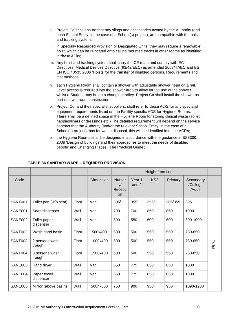
21CS MIM: Authority’s Construction Requirements Version, Part 1 193
k. Project Co shall ensure that any slings and accessories owned by the Authority (and
each School Entity, in the case of a School(s) project), are compatible with the hoist
and tracking system;
l. in Specially Resourced Provision or Designated Units, they may require a removable
hoist, which can be relocated onto ceiling mounted tracks in other rooms as identified
in these ACRs;
m. Any hoist and tracking system shall carry the CE mark and comply with EC
Directives: Medical Devices Directive (93/42/EEC) as amended 2007/47/EC and BS
EN ISO 10535:2006 ‘Hoists for the transfer of disabled persons. Requirements and
test methods’;
n. each Hygiene Room shall contain a shower with adjustable shower head on a rail.
Level access is required into the shower area to allow for the use of the shower
whilst a Student may be on a changing trolley. Project Co shall install the shower as
part of a wet room construction;
o. Project Co, and their specialist suppliers, shall refer to these ACRs for any specialist
equipment requirements listed on the Facility specific ADS for Hygiene Rooms.
There shall be a defined space in the Hygiene Room for storing clinical waste (soiled
nappies/liners or dressings etc.) The detailed requirement will depend on the service
contract that the Authority (and/or the relevant School Entity, in the case of a
School(s) project), has for waste disposal, this will be identified in these ACRs;
p. the Hygiene Rooms shall be designed in accordance with the guidance in BS8300:
2009 ‘Design of buildings and their approaches to meet the needs of disabled
people’ and Changing Places: ‘The Practical Guide’;
TABLE 36 SANITARYWARE – REQUIRED PROVISION
Height from floor
Code
Dimension Nurser
y/
Recepti
on
Year 1
and 2
KS2 Primary Secondary
/College
/Adult
SANT001 Toilet pan (w/o seat) Floor Var 3051 3551 3551 305/355 395
Toile
t
SANE001 Soap dispenser Wall Var 700 700 850 850 1000
SANE002 Toilet paper dispenser
Wall Var 500 550 600 600 800-1000
SANT002 Wash hand basin Floor 500x400 500 500 550 550 750-850
SANT003 2 persons wash trough
Floor 1000x400 500 500 550 550 750-850
SANT004 3 persons wash trough
Floor 1500x400 500 500 550 550 750-850
SANE003 Hand dryer Wall Var 650 775 850 850 1000
SANE004 Paper towel dispenser
Wall Var 650 775 850 850 1000
SANE005 Mirror (above basin) Wall 500hx600 750 900 950 950 1090-1200
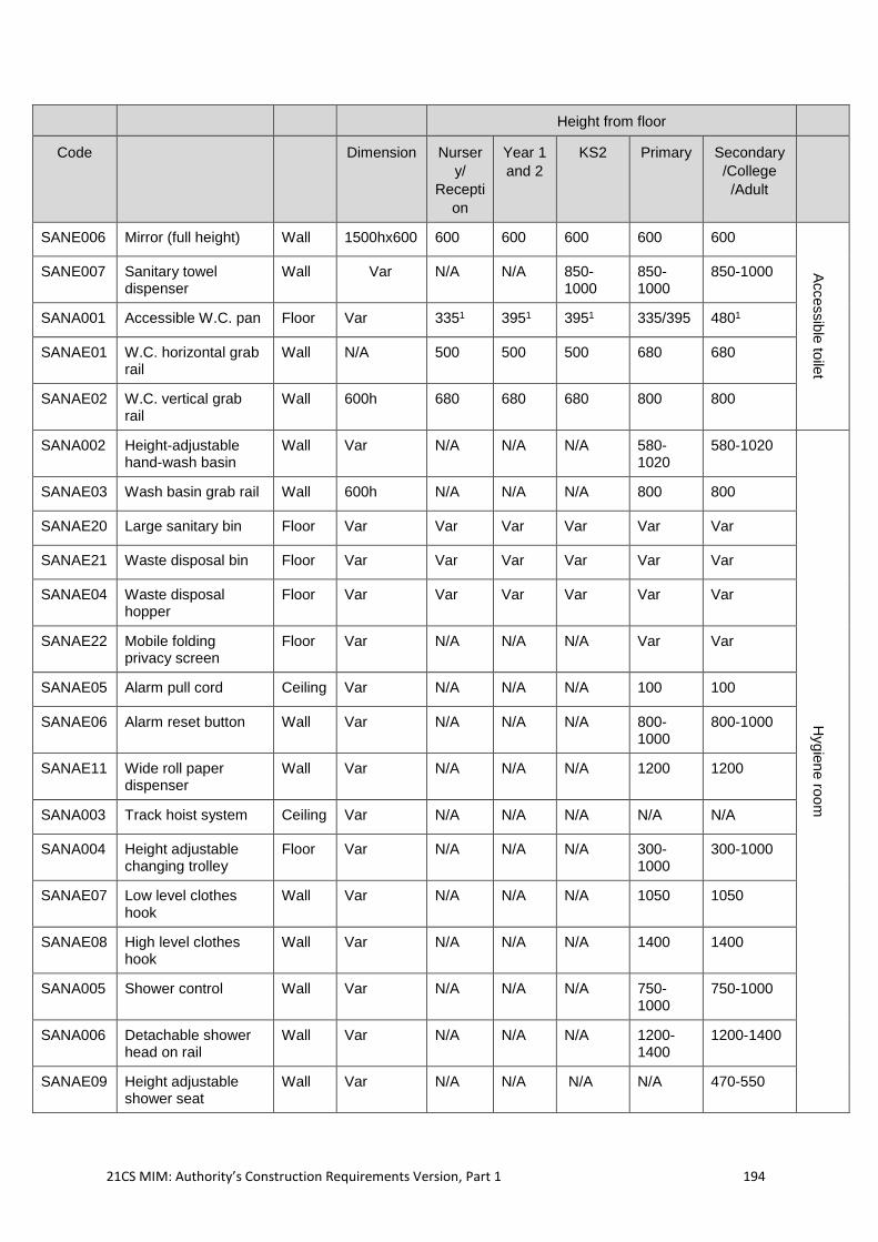
21CS MIM: Authority’s Construction Requirements Version, Part 1 194
Height from floor
Code
Dimension Nurser
y/
Recepti
on
Year 1
and 2
KS2 Primary Secondary
/College
/Adult
SANE006 Mirror (full height) Wall 1500hx600 600 600 600 600 600
Accessib
le to
ilet
SANE007 Sanitary towel dispenser
Wall Var N/A N/A 850-1000
850-1000
850-1000
SANA001 Accessible W.C. pan Floor Var 3351 3951 3951 335/395 4801
SANAE01 W.C. horizontal grab rail
Wall N/A 500 500 500 680 680
SANAE02 W.C. vertical grab rail
Wall 600h 680 680 680 800 800
SANA002 Height-adjustable hand-wash basin
Wall Var N/A N/A N/A 580-1020
580-1020
Hygie
ne ro
om
SANAE03 Wash basin grab rail Wall 600h N/A N/A N/A 800 800
SANAE20 Large sanitary bin Floor Var Var Var Var Var Var
SANAE21 Waste disposal bin Floor Var Var Var Var Var Var
SANAE04 Waste disposal hopper
Floor Var Var Var Var Var Var
SANAE22 Mobile folding privacy screen
Floor Var N/A N/A N/A Var Var
SANAE05 Alarm pull cord Ceiling Var N/A N/A N/A 100 100
SANAE06 Alarm reset button Wall Var N/A N/A N/A 800-1000
800-1000
SANAE11 Wide roll paper dispenser
Wall Var N/A N/A N/A 1200 1200
SANA003 Track hoist system Ceiling Var N/A N/A N/A N/A N/A
SANA004 Height adjustable changing trolley
Floor Var N/A N/A N/A 300-1000
300-1000
SANAE07 Low level clothes hook
Wall Var N/A N/A N/A 1050 1050
SANAE08 High level clothes hook
Wall Var N/A N/A N/A 1400 1400
SANA005 Shower control Wall Var N/A N/A N/A 750-1000
750-1000
SANA006 Detachable shower head on rail
Wall Var N/A N/A N/A 1200-1400
1200-1400
SANAE09 Height adjustable shower seat
Wall Var N/A N/A N/A N/A 470-550
21CS MIM: Authority’s Construction Requirements Version, Part 1 195
2.11.28 Gas and compressed air installations
2.11.28.1 The design, installation and maintenance of any gas and compressed air installations provided shall comply with the Gas Safety (Installation and Use) Regulations (GSIUR) and shall be in accordance with the guidelines set out in IGEM/UP/11 ‘Gas installations for educational establishments’ and other applicable IGEM standards, relevant British standards and UKLPG documents.
2.11.28.2 Project Co shall ensure that the following requirements are met:
gas supplies are interlocked with ventilation systems as required by the GSUIR
and IGEM standards;
gas installations are certified on completion to comply with the GSUIR, IGEM
standards and British standards and all HSE and UKLPG recommendations and
requirements;
automatic Isolation Valves in accordance with IGEM/UP/11 are fitted to science
gas supplies, and positioned near the teacher’s desk/board, or next to main light
switches or at the entrance to the laboratory;
design and installation of emergency control valves (ECVs), additional emergency
control valves (AECVs) and automatic isolation valves (AIVs) complies with
IGEM/UP/11; and
where gas pipework runs in ceiling spaces or behind or inside furniture, a high
and low-level vent is provided to avoid a build-up of gas as described in
IGEM/UP/11 and IGEM/UP/2.
2.11.28.3 Gas appliances can be of three types:
Type A appliances are those that do not require a flue to be fitted to them and
include Bunsen burners, flue less appliances, e.g., some types of flueless gas
fire, and most domestic and catering cookers/ranges;
Type B appliances are those appliances that require a flue pipe and are referred
to as open flued appliances (such as a gas fire, a kiln, gas fired boilers or hot
water heaters, appliances in gas fitting workshops in Colleges or some types of
larger specialist cooking appliance, e.g., fish fryer ranges); and
Type C appliances are referred to as room sealed (or balanced flue) and are
typical of modern domestic or commercial gas boilers and may be used for
heating or as appliances in gas fitting workshops in Colleges’.
2.11.29 Gas Interlocks
2.11.29.1 An interlock is required between gas supply and mechanical ventilation to ensure that gas will not be supplied when there is an inadequate airflow. This is for safe operation of appliances and equipment and the safety of personnel.
2.11.29.2 For Type B appliances, Regulation 27(4) of GSIUR requires that any mechanical extract system that is required for safe operation of the appliances must be interlocked with the gas supply. IGEM/UP/19 provides more detailed requirements for interlock systems. It states that:
“For Type B appliances, environmental monitoring such as CO2, temperature or
humidity may be used in conjunction with variable speed drive (VSD) systems.
However, fan flow/pressures switches or power monitoring shall always be used
in conjunction with Type B catering appliances. CO2, temperature or humidity
monitoring is not acceptable as the main interlock for Type B catering
appliances.”
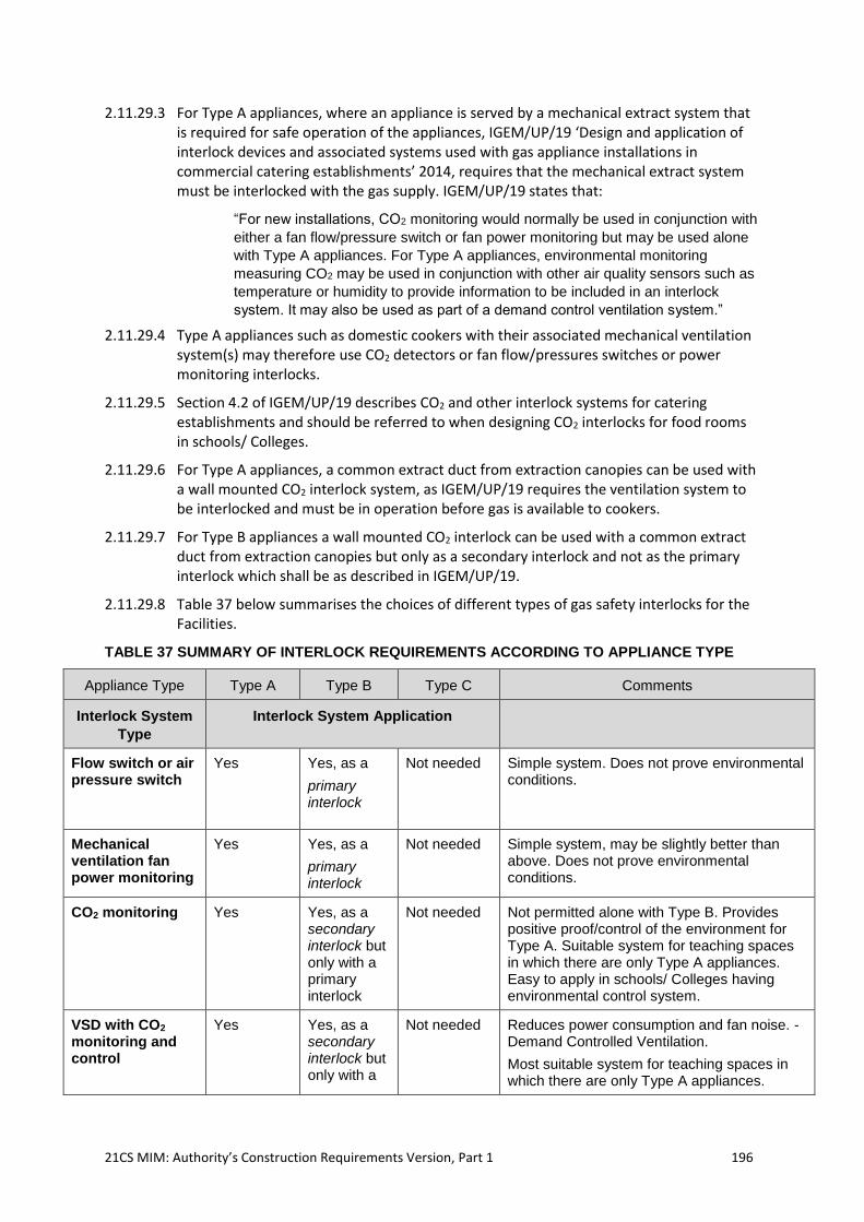
21CS MIM: Authority’s Construction Requirements Version, Part 1 196
2.11.29.3 For Type A appliances, where an appliance is served by a mechanical extract system that is required for safe operation of the appliances, IGEM/UP/19 ‘Design and application of interlock devices and associated systems used with gas appliance installations in commercial catering establishments’ 2014, requires that the mechanical extract system must be interlocked with the gas supply. IGEM/UP/19 states that:
“For new installations, CO2 monitoring would normally be used in conjunction with
either a fan flow/pressure switch or fan power monitoring but may be used alone
with Type A appliances. For Type A appliances, environmental monitoring
measuring CO2 may be used in conjunction with other air quality sensors such as
temperature or humidity to provide information to be included in an interlock
system. It may also be used as part of a demand control ventilation system.”
2.11.29.4 Type A appliances such as domestic cookers with their associated mechanical ventilation system(s) may therefore use CO2 detectors or fan flow/pressures switches or power monitoring interlocks.
2.11.29.5 Section 4.2 of IGEM/UP/19 describes CO2 and other interlock systems for catering establishments and should be referred to when designing CO2 interlocks for food rooms in schools/ Colleges.
2.11.29.6 For Type A appliances, a common extract duct from extraction canopies can be used with a wall mounted CO2 interlock system, as IGEM/UP/19 requires the ventilation system to be interlocked and must be in operation before gas is available to cookers.
2.11.29.7 For Type B appliances a wall mounted CO2 interlock can be used with a common extract duct from extraction canopies but only as a secondary interlock and not as the primary interlock which shall be as described in IGEM/UP/19.
2.11.29.8 Table 37 below summarises the choices of different types of gas safety interlocks for the Facilities.
TABLE 37 SUMMARY OF INTERLOCK REQUIREMENTS ACCORDING TO APPLIANCE TYPE
Appliance Type Type A Type B Type C Comments
Interlock System
Type
Interlock System Application
Flow switch or air pressure switch
Yes Yes, as a
primary interlock
Not needed Simple system. Does not prove environmental conditions.
Mechanical ventilation fan power monitoring
Yes Yes, as a
primary interlock
Not needed Simple system, may be slightly better than above. Does not prove environmental conditions.
CO2 monitoring Yes Yes, as a secondary interlock but only with a primary interlock
Not needed Not permitted alone with Type B. Provides positive proof/control of the environment for Type A. Suitable system for teaching spaces in which there are only Type A appliances. Easy to apply in schools/ Colleges having environmental control system.
VSD with CO2
monitoring and control
Yes Yes, as a secondary interlock but only with a
Not needed Reduces power consumption and fan noise. - Demand Controlled Ventilation.
Most suitable system for teaching spaces in which there are only Type A appliances.
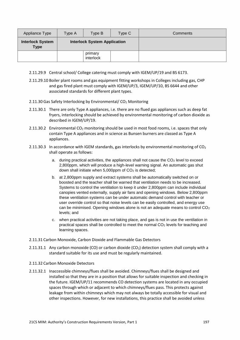
21CS MIM: Authority’s Construction Requirements Version, Part 1 197
Appliance Type Type A Type B Type C Comments
Interlock System
Type
Interlock System Application
primary interlock
2.11.29.9 Central school/ College catering must comply with IGEM/UP/19 and BS 6173.
2.11.29.10 Boiler plant rooms and gas equipment fitting workshops in Colleges including gas, CHP and gas fired plant must comply with IGEM/UP/3, IGEM/UP/10, BS 6644 and other associated standards for different plant types.
2.11.30 Gas Safety Interlocking by Environmental/ CO2 Monitoring
2.11.30.1 There are only Type A appliances, i.e. there are no flued gas appliances such as deep fat fryers, interlocking should be achieved by environmental monitoring of carbon dioxide as described in IGEM/UP/19.
2.11.30.2 Environmental CO2 monitoring should be used in most food rooms, i.e. spaces that only contain Type A appliances and in science as Bunsen burners are classed as Type A appliances.
2.11.30.3 In accordance with IGEM standards, gas interlocks by environmental monitoring of CO2 shall operate as follows:
a. during practical activities, the appliances shall not cause the CO2 level to exceed
2,800ppm, which will produce a high-level warning signal. An automatic gas shut
down shall initiate when 5,000ppm of CO2 is detected;
b. at 2,800ppm supply and extract systems shall be automatically switched on or
boosted and the teacher shall be warned that ventilation needs to be increased.
Systems to control the ventilation to keep it under 2,800ppm can include individual
canopies vented externally, supply air fans and opening windows. Below 2,800ppm
these ventilation systems can be under automatic demand control with teacher or
user override control so that noise levels can be easily controlled, and energy use
can be minimised. Opening windows alone is not an adequate means to control CO2
levels; and
c. when practical activities are not taking place, and gas is not in use the ventilation in
practical spaces shall be controlled to meet the normal CO2 levels for teaching and
learning spaces.
2.11.31 Carbon Monoxide, Carbon Dioxide and Flammable Gas Detectors
2.11.31.1 Any carbon monoxide (CO) or carbon dioxide (CO2) detection system shall comply with a standard suitable for its use and must be regularly maintained.
2.11.32 Carbon Monoxide Detectors
2.11.32.1 Inaccessible chimneys/flues shall be avoided. Chimneys/flues shall be designed and installed so that they are in a position that allows for suitable inspection and checking in the future. IGEM/UP/11 recommends CO detection systems are located in any occupied spaces through which or adjacent to which chimneys/flues pass. This protects against leakage from within chimneys which may not always be totally accessible for visual and other inspections. However, for new installations, this practice shall be avoided unless
21CS MIM: Authority’s Construction Requirements Version, Part 1 198
suitable and detailed plans for ongoing inspection and maintenance of the chimney/flue have been developed.
2.11.32.2 IGEM/UP/11 recommends that CO detectors are located adjacent to kilns, positioned in accordance with the detector manufacturer’s instructions, as even during normal use they can produce significant levels of CO as part of the process of obtaining colours in the glazes.
2.11.32.3 There is no need for CO detection in boiler houses that have been correctly designed and ventilated in accordance with current industry practice (such as the guidance contained in IGEM/UP/10). Where a site-specific risk assessment identifies the need for CO detection in a boiler house, the equipment shall be fit for purpose and installed and located in accordance with the manufacturer’s instructions and compliant with relevant standards. CO alarms compliant with BS EN 50291 are specifically designed and tested for domestic and recreational spaces. This standard is not intended for detectors for use in Schools, Colleges or workplaces.
2.11.32.4 Detectors complying with BS EN 45544-3 shall be used. Note that not all the requirements of this standard may be necessary as the standard covers much more arduous industrial environments than Schools/Colleges. The variety of applications for CO detection within all educational establishments requires the selection by a competent person of the most appropriate CO detector for that location. For example, it could be that a detector declaring compliance with only some aspects of BS EN 45544-3 would be appropriate within a boiler room adjacent to a corridor. Whereas more of the requirements or clauses might be relevant for a more process combustion orientated location.
2.11.32.5 CO detectors in new installations shall be hard wired.
2.11.33 Carbon Dioxide Detectors
2.11.33.1 CO2 detectors used for gas safety interlocking shall be designed to operate in commercial catering environments. These are required in catering Kitchens, science labs, Design and Technology heat bays and food rooms. They are required to give an audible alarm and be linked with an automatic gas shut off system, which will be fail-safe and require manual intervention in order to restore the gas supply.
2.11.33.2 Where CO2 monitors are used as part of the ventilation control or alarm strategy, the monitors shall be placed in an area that reflects the general CO2 levels within the practical area or cooking area. Typically, they should be fitted horizontally between 1 m and 3 m from cooking or practical areas and approximately 2.5 m above floor level. They shall not be located in high velocity air streams such as close to the edge of a canopy or adjacent to an air supply or extract position.
2.11.33.3 CO2 detectors must be hard wired and installed in accordance with manufacturer’s instructions.
2.11.34 Flammable Gas Detectors
2.11.34.1 Flammable gas detection shall be provided in the boiler room if it is LPG fired or if it is not possible to lock the boiler room. However, all boiler rooms should be lockable. Particular attention needs to be given to the selection and location of flammable gas detection systems where LPG is supplied to boiler rooms.
2.11.35 Gas Systems in Food Rooms
21CS MIM: Authority’s Construction Requirements Version, Part 1 199
2.11.35.1 Where there are only Type A appliances, i.e there are no flued gas appliances such as deep fat fryers, interlocking may be achieved by environmental CO2 monitoring of carbon dioxide as described in IGEM/UP/19.
2.11.35.2 Where provided for in the Site Specific Brief, Project Co may provide gas-free, electric based food teaching rooms. However, in most Schools/Colleges a mixture of electric and gas cookers is traditionally required, to enable Students to experience both gas and electric cooking. Rooms for teaching catering will need gas, as that is what is used in industrial Kitchens.
2.11.36 Laboratory Gas Systems
2.11.36.1 Gas interlocking should be achieved by environmental CO2 monitoring as described in IGEM/UP/19.
2.11.36.2 Project Co shall ensure that gas and compressed air installations and appliances are provided where stated in the ADS and that they are designed, commissioned and maintained in accordance with the requirements of the Institute of Gas Engineers and Managers (IGEM)44.
2.11.36.3 Project Co shall ensure that:
gas supplies to Kitchen equipment are interlocked with the mechanical ventilation
system as appropriate;
gas and CO2 detection equipment interlocked with safety shut-off valves are
installed in all boiler rooms; and
gas installations are certified on completion to comply with all HSE and IGEM
recommendations and requirements.
2.11.36.4 Central Automatic emergency shut off valves without leak detection shall be provided on gas supplies in each science laboratory and science prep room and as specified in the ADS. These shall preferably be positioned near the teacher’s desk/board, next to main light switches or at the entrance to the laboratory. Gas valves shall comply with Gas installations for educational establishments, IGEM/UP/11 Edition 2 published by IGEM, www.igem.org.uk ‘Gas installations for educational establishments’ and other applicable IGEM standards.
2.11.37 Controls, Building, and Energy Management Systems
2.11.37.1 Project Co shall ensure that the design of any Building Services controls, Building Management Systems (BMS), and Energy Management Systems (EMS) meets the requirements within this section.
2.11.37.2 The principal aims of the controls systems for the Facilities shall be:
the effective management of the Building Services systems installed;
to maintain a comfortable environment for occupants that are appropriate to the
activity within the space;
to manage energy consumption and minimise carbon emissions through efficient
use of installed Building Services systems;
to enable user control without undue complexity;
41 Gas installations for educational establishments, IGEM, IGEM/UP/11 Edition 2, 2010 www.igem.org.uk
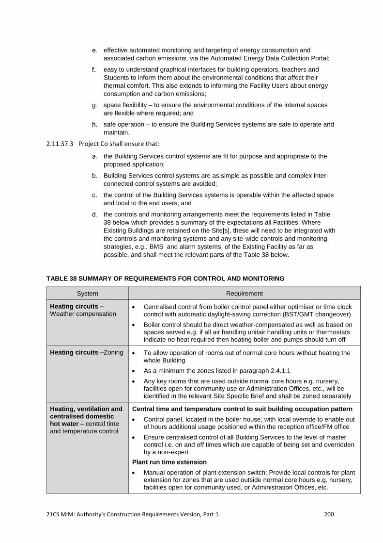
21CS MIM: Authority’s Construction Requirements Version, Part 1 200
effective automated monitoring and targeting of energy consumption and
associated carbon emissions, via the Automated Energy Data Collection Portal;
easy to understand graphical interfaces for building operators, teachers and
Students to inform them about the environmental conditions that affect their
thermal comfort. This also extends to informing the Facility Users about energy
consumption and carbon emissions;
space flexibility – to ensure the environmental conditions of the internal spaces
are flexible where required; and
safe operation – to ensure the Building Services systems are safe to operate and
maintain.
2.11.37.3 Project Co shall ensure that:
the Building Services control systems are fit for purpose and appropriate to the
proposed application;
Building Services control systems are as simple as possible and complex inter-
connected control systems are avoided;
the control of the Building Services systems is operable within the affected space
and local to the end users; and
the controls and monitoring arrangements meet the requirements listed in Table
38 below which provides a summary of the expectations all Facilities. Where
Existing Buildings are retained on the Site[s], these will need to be integrated with
the controls and monitoring systems and any site-wide controls and monitoring
strategies, e.g., BMS and alarm systems, of the Existing Facility as far as
possible, and shall meet the relevant parts of the Table 38 below.
TABLE 38 SUMMARY OF REQUIREMENTS FOR CONTROL AND MONITORING
System Requirement
Heating circuits – Weather compensation
• Centralised control from boiler control panel either optimiser or time clock control with automatic daylight-saving correction (BST/GMT changeover)
• Boiler control should be direct weather-compensated as well as based on spaces served e.g. if all air handling unitair handling units or thermostats indicate no heat required then heating boiler and pumps should turn off
Heating circuits –Zoning • To allow operation of rooms out of normal core hours without heating the whole Building
• As a minimum the zones listed in paragraph 2.4.1.1
• Any key rooms that are used outside normal core hours e.g. nursery, facilities open for community use or Administration Offices, etc., will be identified in the relevant Site Specific Brief and shall be zoned separately
Heating, ventilation and centralised domestic hot water – central time and temperature control
Central time and temperature control to suit building occupation pattern
• Control panel, located in the boiler house, with local override to enable out of hours additional usage positioned within the reception office/FM office
• Ensure centralised control of all Building Services to the level of master control i.e. on and off times which are capable of being set and overridden by a non-expert
Plant run time extension
• Manual operation of plant extension switch: Provide local controls for plant extension for zones that are used outside normal core hours e.g. nursery, facilities open for community used, or Administration Offices, etc.
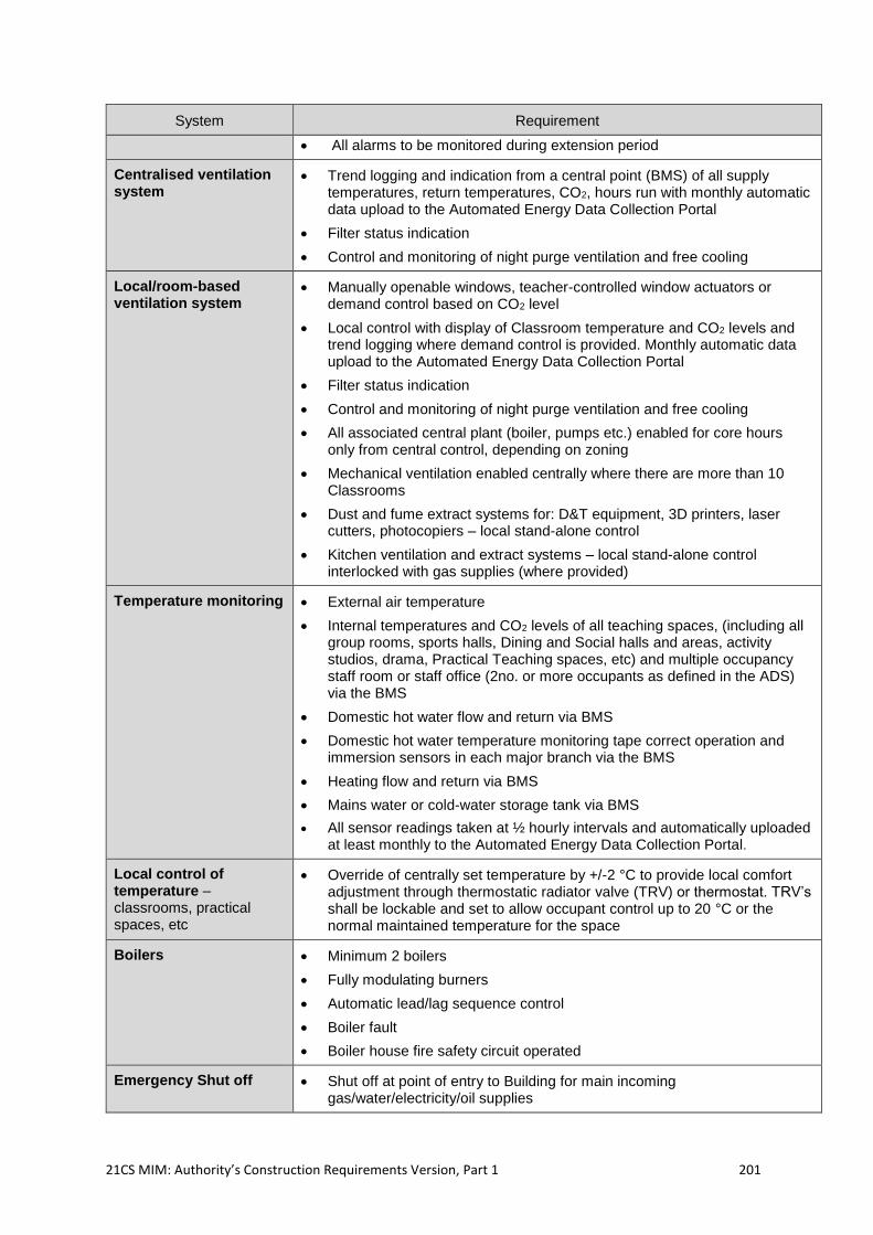
21CS MIM: Authority’s Construction Requirements Version, Part 1 201
System Requirement
• All alarms to be monitored during extension period
Centralised ventilation system
• Trend logging and indication from a central point (BMS) of all supply temperatures, return temperatures, CO2, hours run with monthly automatic data upload to the Automated Energy Data Collection Portal
• Filter status indication
• Control and monitoring of night purge ventilation and free cooling
Local/room-based ventilation system
• Manually openable windows, teacher-controlled window actuators or demand control based on CO2 level
• Local control with display of Classroom temperature and CO2 levels and trend logging where demand control is provided. Monthly automatic data upload to the Automated Energy Data Collection Portal
• Filter status indication
• Control and monitoring of night purge ventilation and free cooling
• All associated central plant (boiler, pumps etc.) enabled for core hours only from central control, depending on zoning
• Mechanical ventilation enabled centrally where there are more than 10 Classrooms
• Dust and fume extract systems for: D&T equipment, 3D printers, laser cutters, photocopiers – local stand-alone control
• Kitchen ventilation and extract systems – local stand-alone control interlocked with gas supplies (where provided)
Temperature monitoring • External air temperature
• Internal temperatures and CO2 levels of all teaching spaces, (including all group rooms, sports halls, Dining and Social halls and areas, activity studios, drama, Practical Teaching spaces, etc) and multiple occupancy staff room or staff office (2no. or more occupants as defined in the ADS) via the BMS
• Domestic hot water flow and return via BMS
• Domestic hot water temperature monitoring tape correct operation and immersion sensors in each major branch via the BMS
• Heating flow and return via BMS
• Mains water or cold-water storage tank via BMS
• All sensor readings taken at ½ hourly intervals and automatically uploaded at least monthly to the Automated Energy Data Collection Portal.
Local control of temperature – classrooms, practical spaces, etc
• Override of centrally set temperature by +/-2 °C to provide local comfort adjustment through thermostatic radiator valve (TRV) or thermostat. TRV’s shall be lockable and set to allow occupant control up to 20 °C or the normal maintained temperature for the space
Boilers • Minimum 2 boilers
• Fully modulating burners
• Automatic lead/lag sequence control
• Boiler fault
• Boiler house fire safety circuit operated
Emergency Shut off • Shut off at point of entry to Building for main incoming gas/water/electricity/oil supplies
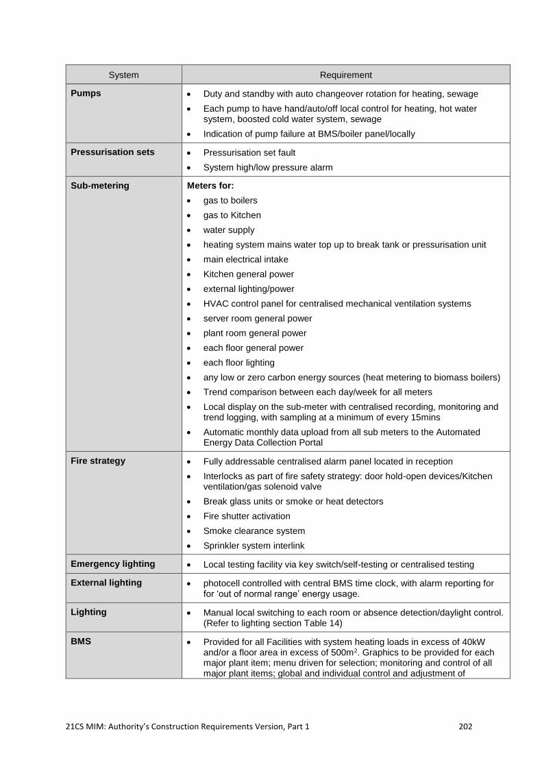
21CS MIM: Authority’s Construction Requirements Version, Part 1 202
System Requirement
Pumps • Duty and standby with auto changeover rotation for heating, sewage
• Each pump to have hand/auto/off local control for heating, hot water system, boosted cold water system, sewage
• Indication of pump failure at BMS/boiler panel/locally
Pressurisation sets • Pressurisation set fault
• System high/low pressure alarm
Sub-metering
Meters for:
• gas to boilers
• gas to Kitchen
• water supply
• heating system mains water top up to break tank or pressurisation unit
• main electrical intake
• Kitchen general power
• external lighting/power
• HVAC control panel for centralised mechanical ventilation systems
• server room general power
• plant room general power
• each floor general power
• each floor lighting
• any low or zero carbon energy sources (heat metering to biomass boilers)
• Trend comparison between each day/week for all meters
• Local display on the sub-meter with centralised recording, monitoring and trend logging, with sampling at a minimum of every 15mins
• Automatic monthly data upload from all sub meters to the Automated Energy Data Collection Portal
Fire strategy • Fully addressable centralised alarm panel located in reception
• Interlocks as part of fire safety strategy: door hold-open devices/Kitchen ventilation/gas solenoid valve
• Break glass units or smoke or heat detectors
• Fire shutter activation
• Smoke clearance system
• Sprinkler system interlink
Emergency lighting • Local testing facility via key switch/self-testing or centralised testing
External lighting • photocell controlled with central BMS time clock, with alarm reporting for for ‘out of normal range’ energy usage.
Lighting • Manual local switching to each room or absence detection/daylight control. (Refer to lighting section Table 14)
BMS • Provided for all Facilities with system heating loads in excess of 40kW and/or a floor area in excess of 500m2. Graphics to be provided for each major plant item; menu driven for selection; monitoring and control of all major plant items; global and individual control and adjustment of
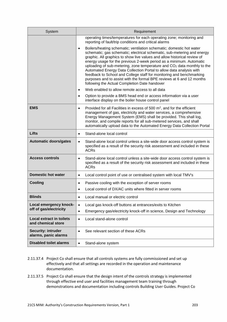
21CS MIM: Authority’s Construction Requirements Version, Part 1 203
System Requirement
operating times/temperatures for each operating zone; monitoring and reporting of fault/trip conditions and critical alarms
• Boilers/heating schematic; ventilation schematic; domestic hot water schematic; gas schematic; electrical schematic, sub-metering and energy graphic. All graphics to show live values and allow historical review of energy usage for the previous 2-week period as a minimum. Automatic uploading of sub-metering, zone temperature and CO2 data monthly to the Automated Energy Data Collection Portal to allow data analysis with feedback to School and College staff for monitoring and benchmarking purposes and to assist with the formal BPE reviews at 6 and 12 months following the Actual Completion Date handover
• Web enabled to allow remote access to all data
• Option to provide a BMS head end or access information via a user interface display on the boiler house control panel
EMS • Provided for all Facilities in excess of 500 m2, and for the efficient management of gas, electricity and water services, a comprehensive Energy Management System (EMS) shall be provided. This shall log, monitor, and compile reports for all sub-metered services, and shall automatically upload data to the Automated Energy Data Collection Portal
Lifts • Stand-alone local control
Automatic doors/gates • Stand-alone local control unless a site-wide door access control system is specified as a result of the security risk assessment and included in these ACRs
Access controls • Stand-alone local control unless a site-wide door access control system is specified as a result of the security risk assessment and included in these ACRs
Domestic hot water • Local control point of use or centralised system with local TMV's
Cooling • Passive cooling with the exception of server rooms
• Local control of DX/AC units where fitted in server rooms
Blinds • Local manual or electric control
Local emergency knock-off of gas/electricity
• Local gas knock-off buttons at entrances/exits to Kitchen
• Emergency gas/electricity knock-off in science, Design and Technology
Local extract in toilets and chemical store
• Local stand-alone control
Security: intruder alarms, panic alarms
• See relevant section of these ACRs
Disabled toilet alarms • Stand-alone system
2.11.37.4 Project Co shall ensure that all controls systems are fully commissioned and set up effectively and that all settings are recorded in the operation and maintenance documentation.
2.11.37.5 Project Co shall ensure that the design intent of the controls strategy is implemented through effective end user and facilities management team training through demonstrations and documentation including controls Building User Guides. Project Co
21CS MIM: Authority’s Construction Requirements Version, Part 1 204
shall undertake seasonal commissioning and adjust the installed Service Infrastructure settings accordingly throughout the 12 months following the Actual Completion Date.
2.11.38 Site-wide Strategy
2.11.38.1 Project Co shall consider the Site as a whole when assessing the controls strategy. Simplicity and ease of use should prevail when designing the site-wide strategy.
2.11.38.2 Project Co shall ensure that the site-wide controls strategy takes into account the occupied periods of the various zones and offers an energy efficient solution.
2.11.38.3 Project Co shall ensure that all Building Services control systems allow for optimum start up and shut off.
2.11.38.4 Project Co shall ensure that the Building Services control systems for relevant plant items are interlinked with the fire alarm interface in accordance with the fire strategy to shut down plant in the event of fire as required.
2.11.38.5 The following sections detail Building Services that may be controlled on/at a local level. There are some systems that are not appropriate for local control and shall be controlled and planned on a site-wide or building-wide scale to have a coordinated strategy. Project Co shall ensure that the following systems are controlled on a site-wide or building-wide scale:
fire detection and alarms;
external lighting;
security; and
access control: where there are existing site-wide access control systems on the
Site, new systems shall integrate with the existing systems, where it is safe to do
so. Where this is not feasible Project Co shall notify the Authority.
2.11.39 Building Services Control Systems and Energy Management Systems (EMS)
2.11.39.1 Project Co shall install controls to allow automatic operation of systems and plant; a BMS and EMS or controls of similar sophistication. Systems must include facilities for remote monitoring, optimisation, weather compensation, scheduling, time extension, frost protection and holiday setting with simple user interfaces. Local control systems shall be IP compatible for future remote connection which may not be supplied initially.
2.11.39.2 Details of the Building Services control systems and energy management systems(EMS) shall be included in the Environmental Strategy Report to be included in Schedule 6 Part 4.
2.11.39.3 A stand-alone control system is provided for all small HVAC systems of limited complexity, which do not warrant being remotely monitored.
2.11.39.4 Headline output data, for example temperatures and heating and hot water flow/return temperatures, is available via the web, interfaced with the AMR data, for use in energy management and in the School/College Curriculum.
2.11.39.5 Project Co shall provide:
detailed specifications and commissioning schedules for the BMS and EMS;
centralised monitoring of mechanical systems through the BMS;
a web-based interface to control systems;
structured security access coding to prevent unauthorised access to the system;
21CS MIM: Authority’s Construction Requirements Version, Part 1 205
provisions for remote dial in by a third party; and
control zones which match the building and system operational zones.
2.11.39.6 A Building Management System (BMS) shall be provided for all Facilities with system heating loads in excess of 40kW and/or a floor area in excess of 500m2 (or extended Buildings which reach this figure).
2.11.39.7 Graphics shall be provided for each major plant item, menu driven for selection; monitoring and control of all major plant items; global and individual control and adjustment of operating times/temperatures for each operating zone; monitoring and reporting of fault/trip conditions and critical alarms.
2.11.39.8 Lighting controls and fire and security systems shall be independent of the BMS.
2.11.39.9 On smaller projects where BMS is not involved, controls shall be simple stand-alone controllers or Programmable Logic Controllers (PLC). Web based monitoring of systems is an alternative for BMS for local monitoring.
2.11.39.10 The use of BMS should only be used in preference to a simpler system in a small building where it can be demonstrated that the BMS will provide greater benefit to outweigh the drawbacks of the BMS being a more complex system to operate and maintain.
2.11.39.11 On very small installations, a domestic-type control system or the boiler manufacturer’s own controls may be sufficient, so long as the Authority (or each relevant School Entity in the case of a School(s) project), is given the additional facility to select a holiday period with frost protection.
2.11.40 Energy Management System (EMS)
2.11.40.1 For the efficient management of gas, electricity and water services a comprehensive energy management system (EMS) shall be provided, to include for the following functionality:
automatic energy/service usage data collection, including for automated upload to
the Automated Energy Data Collection Portal independent of the Authority's (or
the relevant School Entity's in the case of a School(s) project) IT system. Project
Co shall liaise with the Automated Energy Data Collection Portal to establish and
agree the data collection requirements and methodologies;
differentiate between core hours energy use and out of hours and holiday period
energy use;
early warning of potential overuse or out of normal range values;
analysis of usage to highlight inefficient practices, out of hours usages, etc.;
archiving and back-up of all received data for a minimum of 36 months;
calculate heating degree day values based upon local weather data;
align the M&T reporting with CIBSE TM54 protocols; and
retain all current collected data values.
2.11.40.2 The EMS software and hardware may be stand-alone from the BMS but must be interlinked to it for ease of navigation from any central supervisor PC or web-access portal. At all instances of BMS to EMS data inter-connection this shall be through a standard open protocol.
2.11.40.3 Refer also to functionality and in-use requirements for the EMS as described in the Service Level Specification.
21CS MIM: Authority’s Construction Requirements Version, Part 1 206
2.11.40.4 All gas, water and electricity meters will report to the EMS. All usage data collected shall be analysed through the EMS system software on a monitoring and targeting (an M&T) basis to indicate areas where action will bring an improvement in energy use and establish usage patterns, identify bad practices and potential overload or phase imbalance problems. M&T related visual alarms and reports shall assist in control actions.
2.11.40.5 M&T reporting facilities shall be provided that will provide precise information on levels and patterns of use and running costs. These reporting facilities will be graphically based with easy to use and understand for the general staff user summary pages for each service, and shall enable the user to:
monitor core hours usage and out of hours usage separately, and provide internal
billing reporting for each third-party client usage;
display period by period data over a user selected date ranges for each different
building zone and service;
identify peak demand levels with times so that causes can be determined and
removed;
show consumption trends over user selected date ranges and for core hours vs.
out of hours use;
analyse real usage against target levels through graphical based M&T;
determine potential supply capacity and power factor problems;
identify the need for maintenance due to increased levels of energy use through
M&T;
automatically supply all relevant energy data for monitoring the building
performance against others on the Automated Energy Data Collection Portal;
produce automated weekly, monthly, and annual energy/service usage reports;
and
identify and report peak demands against utility provider constraints.
2.11.40.6 Project Co shall submit for approval all proposals for the entire EMS functionality and graphics pages.
2.11.41 Zoning
2.11.41.1 Project Co shall ensure that the Facility is zoned appropriately to ensure that:
spaces are flexible in use;
spaces can be used in isolation out of hours where required;
Service Infrastructure can be controlled to account for differing weather/solar gain
characteristics; and
as a minimum, ensure that the heating and cooling is zoned so that the following
are provided with separate zones:
i. the main catering Kitchen;
ii. sports facilities, including changing areas, showers, and toilets;
iii. main hall, including any catering facilities, toilets and connecting corridors;
iv. any other spaces as identified in these ACRs e.g. Nursery, Community use rooms, and
before and after school clubs; and
v. each floor/level of the Building except in Buildings under 500m2.
2.11.41.2 If centralised mechanical ventilation is used, Project Co shall ensure that the same zones are provided as that for heating or cooling. However, the zones for mechanical ventilation
21CS MIM: Authority’s Construction Requirements Version, Part 1 207
may not be provided through separate systems but can be met through dampers and other controls methods.
2.11.42 Controls Operability and ease of use
2.11.42.1 Project Co shall ensure that all user controls shall be easy to use, well labelled, and intuitive to operate and understand. The design Guide “Controls for end users”45 shall be used by Project Co to succinctly inform the design, installation, training, and handover of the various building controls systems.
2.11.43 Sub-Metering Requirements
2.11.43.1 Sub-meters provided should be intelligent digital MODBUS or M-Bus sub-meters, providing sampling at a minimum of every 30 minutes. Basic pulse output sub-meters will not be acceptable. All sub-meters shall be suitable for billing purposes in accordance the measuring instruments directive (MID) 2004/22/EC
2.11.43.2 Project Co shall ensure that:
all data collected from the sub-meters shall be logged, recorded and analysed in
line with the requirements set out in these ACRs; and
automatic meters shall be installed complete with interface units for connection to
the EMS to allow for automatic meter reading and data collection and automatic
monthly uploading of data to the Automated Energy Data Collection Portal
2.11.44 Heating System Controls
2.11.44.1 Project Co shall ensure that the heating system/s are adequately controllable to give good thermal comfort while maximising energy efficiency and minimising carbon emissions.
2.11.44.2 The control options for switching on and off include manual, time switch, optimisers and programmable controllers. A compensator, used to regulate the operating temperature of a heating system in response to the outside air temperature, shall be used for variable temperature circuits.
2.11.44.3 Project Co shall ensure that the following requirements are met:
room sensors are positioned appropriately, out of draughts and direct sunlight
and at an appropriate height in the room and that the space is suitably zoned to
be controlled by room sensors;
weather compensated heating and centralised control from the boiler control
panel is provided as either optimiser or time clock control with automatic daylight-
saving correction (BST/GMT changeover);
control override is provided to enable out-of-hours use;
the particular thermal comfort needs of Students with complex disabilities or SEN
(D) are taken into consideration when designing the heating system. in
accordance with Building Bulletin 101: ‘Guidelines on ventilation, thermal comfort
and indoor air quality in schools’ (BB101);
45 “Controls for end users: A guide for good design and implementation (BCIA/2007)”, as published by the Building Controls Industry Association in conjunction with BSRIA and the UBT. http://www.bcia.co.uk/documents/Controls%20for%20End%20Users%20guide.pdf
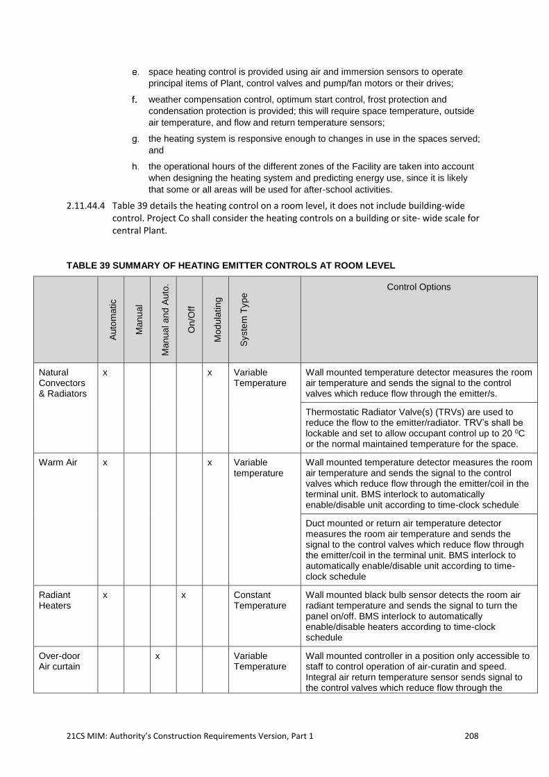
21CS MIM: Authority’s Construction Requirements Version, Part 1 208
space heating control is provided using air and immersion sensors to operate
principal items of Plant, control valves and pump/fan motors or their drives;
weather compensation control, optimum start control, frost protection and
condensation protection is provided; this will require space temperature, outside
air temperature, and flow and return temperature sensors;
the heating system is responsive enough to changes in use in the spaces served;
and
the operational hours of the different zones of the Facility are taken into account
when designing the heating system and predicting energy use, since it is likely
that some or all areas will be used for after-school activities.
2.11.44.4 Table 39 details the heating control on a room level, it does not include building-wide control. Project Co shall consider the heating controls on a building or site- wide scale for central Plant.
TABLE 39 SUMMARY OF HEATING EMITTER CONTROLS AT ROOM LEVEL
Auto
matic
Manu
al
Manu
al an
d A
uto
.
On/O
ff
Modu
latin
g
Syste
m T
ype
Control Options
Natural Convectors & Radiators
x
x Variable Temperature
Wall mounted temperature detector measures the room air temperature and sends the signal to the control valves which reduce flow through the emitter/s.
Thermostatic Radiator Valve(s) (TRVs) are used to reduce the flow to the emitter/radiator. TRV’s shall be lockable and set to allow occupant control up to 20 0C or the normal maintained temperature for the space.
Warm Air x x Variable temperature
Wall mounted temperature detector measures the room air temperature and sends the signal to the control valves which reduce flow through the emitter/coil in the terminal unit. BMS interlock to automatically enable/disable unit according to time-clock schedule
Duct mounted or return air temperature detector measures the room air temperature and sends the signal to the control valves which reduce flow through the emitter/coil in the terminal unit. BMS interlock to automatically enable/disable unit according to time-clock schedule
Radiant Heaters
x
x
Constant Temperature
Wall mounted black bulb sensor detects the room air radiant temperature and sends the signal to turn the panel on/off. BMS interlock to automatically enable/disable heaters according to time-clock schedule
Over-door Air curtain
x Variable Temperature
Wall mounted controller in a position only accessible to staff to control operation of air-curatin and speed. Integral air return temperature sensor sends signal to the control valves which reduce flow through the
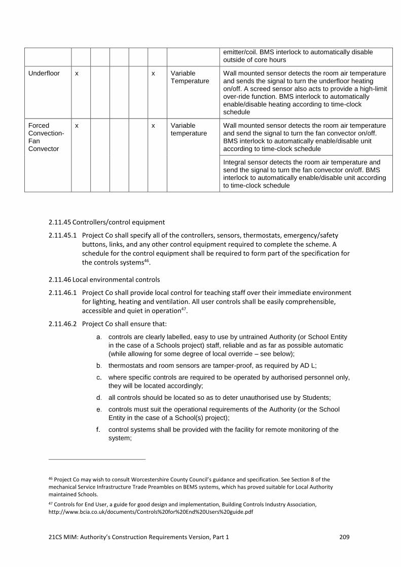
21CS MIM: Authority’s Construction Requirements Version, Part 1 209
emitter/coil. BMS interlock to automatically disable outside of core hours
Underfloor x
x Variable Temperature
Wall mounted sensor detects the room air temperature and sends the signal to turn the underfloor heating on/off. A screed sensor also acts to provide a high-limit over-ride function. BMS interlock to automatically enable/disable heating according to time-clock schedule
Forced Convection- Fan Convector
x
x Variable temperature
Wall mounted sensor detects the room air temperature and send the signal to turn the fan convector on/off. BMS interlock to automatically enable/disable unit according to time-clock schedule
Integral sensor detects the room air temperature and send the signal to turn the fan convector on/off. BMS interlock to automatically enable/disable unit according to time-clock schedule
2.11.45 Controllers/control equipment
2.11.45.1 Project Co shall specify all of the controllers, sensors, thermostats, emergency/safety buttons, links, and any other control equipment required to complete the scheme. A schedule for the control equipment shall be required to form part of the specification for the controls systems46.
2.11.46 Local environmental controls
2.11.46.1 Project Co shall provide local control for teaching staff over their immediate environment for lighting, heating and ventilation. All user controls shall be easily comprehensible, accessible and quiet in operation47.
2.11.46.2 Project Co shall ensure that:
controls are clearly labelled, easy to use by untrained Authority (or School Entity
in the case of a Schools project) staff, reliable and as far as possible automatic
(while allowing for some degree of local override – see below);
thermostats and room sensors are tamper-proof, as required by AD L;
where specific controls are required to be operated by authorised personnel only,
they will be located accordingly;
all controls should be located so as to deter unauthorised use by Students;
controls must suit the operational requirements of the Authority (or the School
Entity in the case of a School(s) project);
control systems shall be provided with the facility for remote monitoring of the
system;
46 Project Co may wish to consult Worcestershire County Council’s guidance and specification. See Section 8 of the mechanical Service Infrastructure Trade Preambles on BEMS systems, which has proved suitable for Local Authority maintained Schools.
47 Controls for End User, a guide for good design and implementation, Building Controls Industry Association, http://www.bcia.co.uk/documents/Controls%20for%20End%20Users%20guide.pdf
21CS MIM: Authority’s Construction Requirements Version, Part 1 210
local control for Facility Users should not be provided over heating temperature
set-point, start time, finish time, regular day omission, or holiday days omission;
temperature set-points for zones of the Building shall only be changed by Project
Co. However, control systems are to be designed to be centrally operable by the
Facility Premises Team to allow short-term time and temperature overrides,
defaulting to automatic operation once a pre-determined period (of up to 24
hours) has elapsed. Changes to the main heating and cooling system
temperature set-points and time schedules must be carried out by Project Co in
consultation with the Authority (or the relevant School Entity in the case of a
School(s) project);
there will be fine trim control provided for room users to change room
temperatures by providing approximately +/-2oC differential from the temperature
set centrally, e.g., by operation of a thermostatic radiator valve or room controller;
ventilation systems are easily controllable to reduce or increase ventilation rates
in response to room temperature and occupancy; and
all space temperature control sensors and thermostats shall be positioned and
arranged so that the maximum difference to the air temperature in the centre of
the room at 1m above the floor is always <3°C. (This does not apply to sensors in
under-floor heating systems that are embedded under-floor to sense floor surface
temperature.)
2.11.47 Ventilation System Controls
2.11.47.1 Project Co shall provide control, trend logging, indication and monitoring of the following for the ventilation systems:
supply temperatures and return temperatures;
CO2 concentration;
filter status;
electrical energy consumed for centralised ventilation systems only;
night purge ventilation and free cooling (where applicable); and
fault detection.
2.11.47.2 Project Co shall ensure that air quality detectors are provided (usually CO2 sensors). Training shall be provided to ensure that staff understand the implications of the detected levels and the appropriate action to take.
2.11.47.3 These ACRs provide specific ventilation control requirements for:
catering Kitchens;
food technology rooms;
science laboratories;
Design and Technology (D&T) workshops and Practical and Vocational Teaching
Spaces, where dust and fume extract systems are provided for D&T equipment,
3D printers and laser cutters; and
photocopiers, where an extract system is provided.
2.11.47.4 In all cases above, local stand-alone control shall be provided.
TABLE 40 SUMMARY OF VENTILATION CONTROLS AT ROOM LEVEL
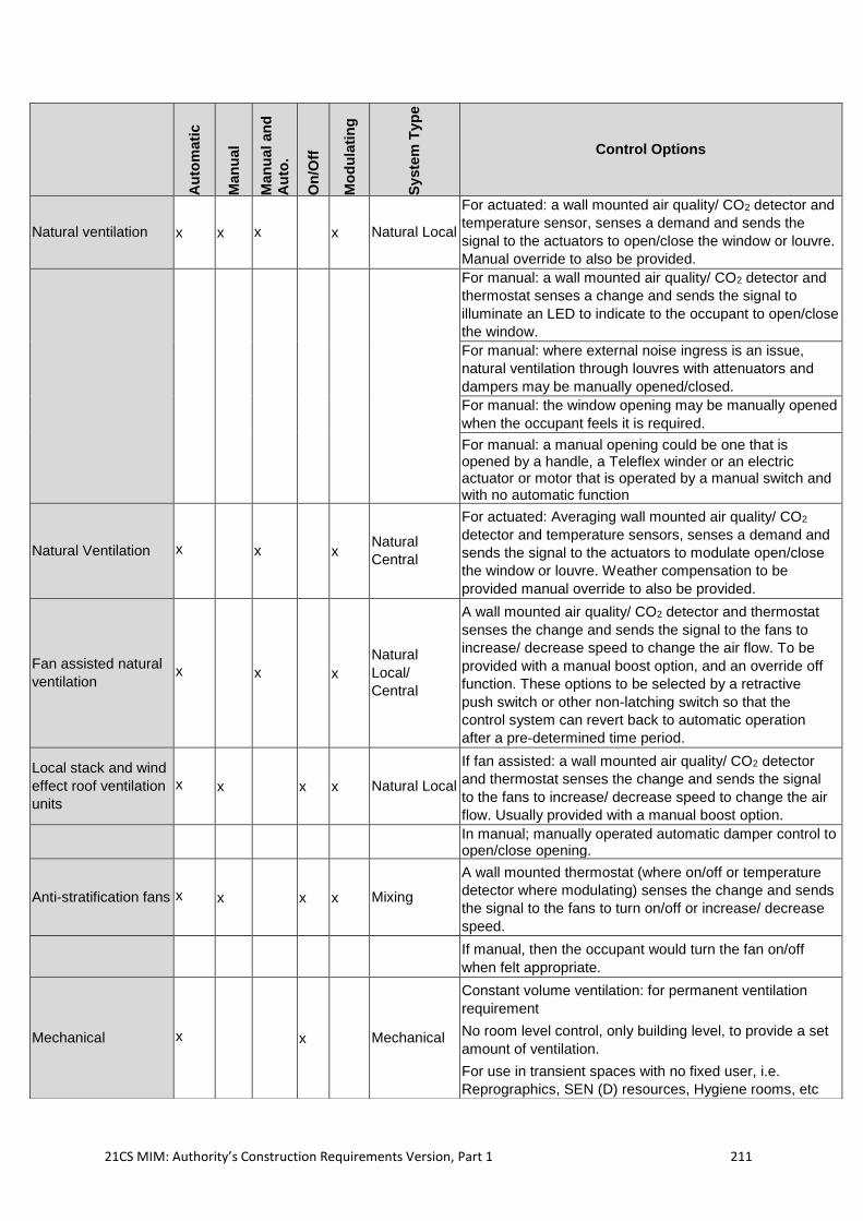
21CS MIM: Authority’s Construction Requirements Version, Part 1 211
Au
tom
ati
c
Man
ual
Man
ual
an
d
Au
to.
On
/Off
Mo
du
lati
ng
Syste
m T
yp
e
Control Options
Natural ventilation x x x x Natural Local
For actuated: a wall mounted air quality/ CO2 detector and
temperature sensor, senses a demand and sends the
signal to the actuators to open/close the window or louvre.
Manual override to also be provided.
For manual: a wall mounted air quality/ CO2 detector and
thermostat senses a change and sends the signal to
illuminate an LED to indicate to the occupant to open/close
the window.
For manual: where external noise ingress is an issue,
natural ventilation through louvres with attenuators and
dampers may be manually opened/closed.
For manual: the window opening may be manually opened
when the occupant feels it is required.
For manual: a manual opening could be one that is opened by a handle, a Teleflex winder or an electric actuator or motor that is operated by a manual switch and with no automatic function
Natural Ventilation x x x Natural
Central
For actuated: Averaging wall mounted air quality/ CO2
detector and temperature sensors, senses a demand and
sends the signal to the actuators to modulate open/close
the window or louvre. Weather compensation to be
provided manual override to also be provided.
Fan assisted natural
ventilation x x x
Natural
Local/
Central
A wall mounted air quality/ CO2 detector and thermostat
senses the change and sends the signal to the fans to
increase/ decrease speed to change the air flow. To be
provided with a manual boost option, and an override off
function. These options to be selected by a retractive
push switch or other non-latching switch so that the
control system can revert back to automatic operation
after a pre-determined time period.
Local stack and wind
effect roof ventilation
units
x x x x Natural Local
If fan assisted: a wall mounted air quality/ CO2 detector
and thermostat senses the change and sends the signal
to the fans to increase/ decrease speed to change the air
flow. Usually provided with a manual boost option.
In manual; manually operated automatic damper control to open/close opening.
Anti-stratification fans x x x x Mixing
A wall mounted thermostat (where on/off or temperature
detector where modulating) senses the change and sends
the signal to the fans to turn on/off or increase/ decrease
speed.
If manual, then the occupant would turn the fan on/off
when felt appropriate.
Mechanical x x Mechanical
Constant volume ventilation: for permanent ventilation
requirement
No room level control, only building level, to provide a set
amount of ventilation.
For use in transient spaces with no fixed user, i.e.
Reprographics, SEN (D) resources, Hygiene rooms, etc
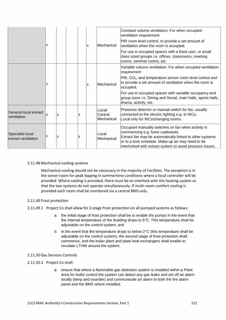
21CS MIM: Authority’s Construction Requirements Version, Part 1 212
2.11.48 Mechanical cooling systems
Mechanical cooling should not be necessary in the majority of Facilities. The exception is in the server room for peak lopping in summertime conditions where a local controller will be provided. Where cooling is provided, there must be an interlock with the heating system so that the two systems do not operate simultaneously. If multi-room comfort cooling is provided each room shall be monitored via a central BMS only.
2.11.49 Frost protection
2.11.49.1 Project Co shall allow for 2-stage frost protection on all pumped systems as follows:
the initial stage of frost protection shall be to enable the pumps in the event that
the internal temperature of the Building drops to 5°C. This temperature shall be
adjustable on the control system; and
in the event that the temperature drops to below 2°C (this temperature shall be
adjustable on the control system), the second stage of frost protection shall
commence, and the boiler plant and plate heat exchangers shall enable to
circulate LTHW around the system.
2.11.50 Gas Services Controls
2.11.50.1 Project Co shall:
ensure that where a flammable gas detection system is installed within a Plant
Area for boiler control the system can detect any gas leaks and set off an alarm
locally (lamp and sounder) and communicate an alarm to both the fire alarm
panel and the BMS where installed;
x x Mechanical
Constant volume ventilation: For when occupied
ventilation requirement
PIR room level control, to provide a set amount of
ventilation when the room is occupied.
For use in occupied spaces with a fixed user, or small
class sized groups i.e. offices, classrooms, meeting
rooms, seminar rooms, etc.
x x Mechanical
Variable volume ventilation: For when occupied ventilation
requirement
PIR, CO2, and temperature sensor room level control and
to provide a set amount of ventilation when the room is
occupied.
For use in occupied spaces with variable occupancy and
group sizes i.e. Dining and Social, main halls, sports halls,
drama, activity, etc.
General local extract ventilation
x x x Local/ Central Mechanical
Presence detector or manual switch for fan, usually
connected to the electric lighting e.g. in WCs.
Local only for WCs/changing rooms.
Specialist local
extract ventilation x x x Local
Mechanical
Occupant manually switches on fan when activity is
commencing e.g. fume cupboards.
Extract fan may be automatically linked to other systems
or to a time schedule. Make-up air may need to be
interlocked with extract system to avoid pressure issues.
21CS MIM: Authority’s Construction Requirements Version, Part 1 213
ensure that the flammable gas detection system complies with IGEM UP/2, that a
fail-safe gas solenoid valve on the gas main is provided and that in the event of a
gas leak being detected this valve will close;
provide emergency push buttons on all exits of Plant Areas which when pressed
close the gas valve and this condition is communicated to the BMS where one is
used;
ensure that in the event of a fire alarm, the gas valve in Plant Areas will close and
that a time delay (adjustable) is included so that during fire alarm testing the
boilers are not shut down;
ensure that emergency push buttons are provided in any laboratories by the
teacher’s desk and Preparation Areas by the exit and that when pressed the gas
valve will close and a local reset is provided;
ensure that each science lab/ Preparation Areas / catering Kitchen/ Classroom is
fitted with a gas isolation/pressure proving system where required by IGEM
UP/11, and that gas proving valves are fitted to each branch serving a science
lab/ Preparation Areas ; and
provide gas safety interlocks in Kitchens, science labs, food technology, Design
and Technology areas which comply with IGEM UP11, IGEM UP19 and BB101.
2.11.51 Control Commissioning
2.11.51.1 Project Co shall:
ensure that the controls systems are fully commissioned throughout prior to the
Actual ICT Handover Date, and ensure that the whole building system
commissioning is undertaken such that the Building Services controls systems
that interact with each other are commissioned at the same time;
ensure that the Building Services control systems are commissioned in
accordance with CIBSE Commissioning Code C: Automatic controls;
provide a commissioning programme prior to construction allowing for 2 weeks’
notice prior to witness testing;
ensure that inspection and testing are undertaken in line with BS 7671:2008
‘Requirements for electrical installations. IET Wiring Regulations’;
commission the controls system in accordance with BSRIA AG 9/2001 ‘Standard
specifications for BMS’;
carry out Building Performance Evaluation and seasonal commissioning in
accordance with these ACRs; and
carry out performance testing/proving during the 12-months following the Actual
Completion Date.
2.11.51.2 Project Co shall conduct seasonal commissioning of the control systems during the 12 months after the Actual Completion Date handover and fine tune control settings.
2.11.51.3 Project Co shall also run, monitor and maintain all Building Services and control systems for a minimum period of one full week beforethe Actual ICT Handover Date, demonstrating that all systems will operate automatically without fault in normal modes of operation. During this period Project Co. shall:
undertake the required demonstration of the system and controls in line with the
Soft Services Training Plan set out in Schedule 10 of this Agreement.
specifically monitor, measure, and calculate all domestic hot water system
standing losses and demonstrate that there are within the calculated and
21CS MIM: Authority’s Construction Requirements Version, Part 1 214
acceptable design parameters and limits as set out in these ACRs and the Final
Baseline Energy model.
2.11.52 Electrical Installations
2.11.52.1 Project Co shall ensure that the design of electrical services meet the requirements for the design, installation and commissioning of the electrical services and the requirements below.
2.11.53 Power, Connections, Supply and Generation
2.11.53.1 Project Co shall make due allowance in the design for the safe access to, and maintenance of, all parts of the electrical installation. The electrical services shall be arranged so that they do not impede access to other Service Infrastructure.
2.11.53.2 Project Co shall arrange for an electrical connection to the public electrical supply (PES) and make allowance for Distribution Network Operator (DNO) equipment to be located on the Site if necessary.
2.11.53.3 Project Co shall:
liaise with the distribution network operator (DNO) to establish the incoming
electricity supply, and determine if the supply should be at high voltage or low
voltage’, establish the rating of the DNO overcurrent device at the point of supply,
and provide the DNO with all characteristics of the load which the DNO may
request (for example harmonic content and characteristics of large loads);
establish the location of DNO equipment, make allowance for it to be located on
the site if necessary, and submit drawings to the Authority showing the layout of
the DNO equipment including high voltage switchgear, transformers, low voltage
switchgear and space for metering following DNO guidelines;
establish and take into account the characteristics of the supply including
prospective short-circuit current, external earth fault loop impedance and earthing
arrangements;
ensure connections to a low voltage (LV) supply are designed in accordance with
BS 7671 IET Wiring Regulations;
ensure electrical supplies are 3 phase, 400V, 50Hz; and
ensure the power factor is no less than 0.95 lagging and provide power factor
correction equipment to achieve this power factor, as necessary on incoming
electrical supplies as well as on low voltage distribution systems with balanced
loads for each phase, as necessary.
2.11.53.4 Project Co shall assess the required capacity of the new electrical supply taking into account diversity factors and the anticipated load profile. Electrical supplies shall be of appropriate voltage and phase for the size of premises.
2.11.53.5 Where the Works are a modification or adaptation of Existing Facilities, Project Co shall assess the capacity of the existing electrical supply and if necessary shall arrange for an enhancement to the supply.
2.11.53.6 Where it is proposed to connect to existing electrical systems, Project Co shall evaluate those electrical systems. Project Co shall make an assessment of their capability and suitability to be connected to or modified in accordance with a valid Electrical Installation Condition Report (EICR).
2.11.53.7 Project Co shall, in consultation with the Authority, make an assessment of potential expansion and change throughout the life of the Building and shall make appropriate
21CS MIM: Authority’s Construction Requirements Version, Part 1 215
provision in the design of the electrical distribution system. In the absence of guidance from the Authority, or any Student number forecasts as part of these ACRs, Project Co shall allow for 20% future expansion of the Facility.
2.11.53.8 Project Co shall ensure that selected energy using equipment and the electrical installation comply with appropriate directives and standards and is installed following good Electro Magnetic Compatibility (EMC) installation practice.
2.11.54 Power Generation Systems
2.11.54.1 Where these systems attract subsidies in the form or feed-in tariffs or similar, Project Co shall ensure that these are registered with the appropriate body (acting as agent for the Authority (or the relevant School Entity/(ies) in the case of a School(s) project), so that the Authority or the School Entity (as relevant) are able to receive the subsidies due.
2.11.55 Standby Generation
2.11.55.1 Generators shall only be provided where they are required to be installed byLaw, for example, for firefighting lifts and for life-safety and fire-fighting applications.
2.11.56 Photovoltaic Systems
2.11.56.1 Welsh Government would expect that all new Buildings to be provided with Photovoltaic panels (PV) as part of the buildings Energy strategy, over and above any minimum requirements to meet Welsh Building Regulations AD L, or as part of BREEAM credits, or other local planning conditions.
2.11.56.2 Within practical and funding limitations, all appropriately orientated pitched roofs and all available flat roofs should be provided with PV arrays. Where these are pitched roofs, the orientation shall be no more than 30° off of true south facing. Where these are flat roof, appropriated pitched and ballasted supports shall be used to align panels to be true south facing. Appropriate and reasonable allowances for roof walkways and access and maintenance space to all roof plant, fixtures and fittings is expected, otherwise all areas of available roof are to be provided with the maximum available area of PV arrays.
2.11.56.3 Project Co shall engage an independent specialist PV designer/installer to review each scheme and advise upon the optimum position and area of PV panels and arrays that can be provided on the roofs. Project Co shall take full account of these recommendations and coordinate the overall design of the Building, including for any roof mounted Service Infrastructure and equipment, and demonstrate that Project Co has provided the maximum coverage of PV panels and arrays as is practical.
2.11.56.4 For all schemes Project Co shall:
undertake the complete design of the system;
ensure the system is designed and installed to BS EN 62124 and in accordance
with ENA G59/3 and ENA G83/1 and to BS EN 61427-1, as well as BS 7671 IET
Wiring Regulations;
produce calculations showing estimated annual energy yield, based upon a PV
module efficiency of at least 17% using a Monocrystalline type panel, or better,
from an established manufacturer;
ensure that the design life of the system is 20 years;
provide for a minimum of 10 year manufactures module warranties, power supply
warranty of 80%+ after 25 years, and 10-year manufacturers inverter warranties;
21CS MIM: Authority’s Construction Requirements Version, Part 1 216
ensure the mode of operation is grid connected and undertake all necessary
liaison and negotiations with the DNO; and
ensure that the positioning of PV panels is such that they are easily and safely
accessible for maintenance and cleaning.
2.11.57 Small Scale Wind Generating Systems
2.11.57.1 Where small scale wind generating systems are required as part of a strategy to meet Welsh Building Regulations AD L or planning conditions, Project Co shall:
undertake the complete design of the system;
ensure the system is designed and installed to BS EN 61400-2 and Renewable
UK ‘Small Wind Turbine Standard’ as well as BS 7671 IET Wiring Regulations;
ensure the mode of operation is grid connected and undertake all necessary
liaison and negotiations with the DNO;
ensure that the design life of the system is a minimum of 20 years;
provide for a minimum of 10 year manufactures warranties;
ensure that the specialist designer and installer are Microgeneration Certification
Scheme accredited; and
submit details to the Authority of the proposed type of wind turbine, its mounting
axis, support structure and foundations, electronic and electrical components,
cabling and cable containment.
2.11.58 Mains Distribution
2.11.58.1 The distribution strategy adopted shall be well-planned, logical, maintainable and cost effective.
2.11.58.2 Electrical rooms and cable routes shall be determined during the early stages of the design to ensure that adequate floor space and horizontal and vertical distribution zones are provided.
2.11.58.3 Cable containment shall be selected and arranged taking into account EMC considerations. Each containment run shall carry cables of only one voltage band and cable containment shall not be suspended from other Service Infrastructure.
2.11.58.4 Steel cable trays, baskets, ladders and trunking shall have an appropriate finish, shall be electrically continuous where metallic and shall have fire barriers where appropriate.
2.11.58.5 Project Co shall ensure that:
main switchboards, sectional switchboards and distribution boards satisfy all
electrical and mechanical criteria and that the switchgear provides for future
extension affecting cabling and electrical loads up to a minimum of 20% above
the base load for the completed Facilities;
all switchboards are installed in secure locations;
new switchboards shall have an appropriate form of separation taking into
account the nature of the loads supplied and any requirements for continuity of
supply. Where it is required that cables may need to be terminated adjacent to
live cables, then the form of separation shall be Form 4b Type 7. Where it is not
required that cables may need to be terminated adjacent to live cables then the
form of separation shall be Form 4 Type 2 or better;
the system achieves the required disconnection times under fault and is properly
graded to achieve full discrimination / selectivity between upstream and
21CS MIM: Authority’s Construction Requirements Version, Part 1 217
downstream devices both on mains operation, and discrimination is demonstrated
using time-current coordination curves in a study report;
where distribution boards are located in accessible locations, such as corridors,
they are tamper proof and fitted with a lockable door; and
all Equipment shall be provided with durable labels, clearly marked with details of
the equipment’s function and designation.
2.11.58.6 Project Co shall provide a main switch panel for the incoming supply that has:
full metering and EMS connections for monitoring and controls;
sufficient switch fuses / moulded case circuit breakers (MCCBs) for sub-main
distribution, lifts, heating, ventilation and air conditioning (HVAC) and fire alarm
along with a minimum of 10% spare capacity;
automatic power factor correction shall be provided where necessary to achieve a
power factor of at least 0.95 in normal use;
local panel boards for larger loads that are remote from the main incoming panel
are fitted with sub-metering and have a minimum of 20% spare capacity and shall
have BMS and EMS connections for monitoring and control; and
local power and lighting distribution boards shall have a minimum of 10% spare
load capacity and 20% spare breaker ways to allow for future expansion of the
system.
2.11.58.7 Project Co shall ensure that:
in all science labs, Preparation Roomsand design technology Practical Teaching
rooms, automatic central isolation of electrical supplies is provided which isolates
all circuits except those provided for ICT equipment;
the following rooms and spaces shall be fed by dedicated distribution boards:
ICT-rich teaching rooms, Practical Teaching rooms with emergency shut off on
electrical supplies, large offices, communications centres, server rooms, Kitchens
and stage lighting rigs;
the server room distribution board serving ICT Equipment is on a separate supply
from the main distribution board so that the server room can be left running while
other areas are shut down for maintenance;
the server room power consumption is separately metered and monitored by the
EMS; and
ICT equipment in the server room is metered after the UPS so that the PUE can
be calculated for energy monitoring purposes. Data projectors and local ICT
equipment in teaching spaces should be on the same phase as all other small
power.
2.11.58.8 Project Co shall provide external weatherproof vehicle charging points to at least 4no. or 10% of the designated on-site car parking spaces (whichever the greater number), including disabled bays, using a ‘pod point’ type charging system, with a minimum of 2no. twin 3.6kW single phase pod points or equivalent serving four car parking bays. For larger sites and quantity of charging points a charging array system may be more economical and should be considered.
2.11.59 Earthing and Bonding Systems
2.11.59.1 Project Co shall:
provide an earthing and bonding installation in accordance with BS 7671 and BS
7430;
21CS MIM: Authority’s Construction Requirements Version, Part 1 218
liaise with the DNO to determine the type of earthing system required and to
establish the demarcation of responsibilities;
provide all earthing and bonding including main incoming earthing, main earth
electrode, main earth terminal (MET), main equipotential bonding, supplementary
equipotential bonding, circuit protective conductors, clean earths where
appropriate and functional earths where appropriate; and
only where generators are required, ensure that the design of standby generator
earthing ensures that sufficient earth fault current is generated to operate
protective devices.
2.11.60 Inspection and Testing of Low Voltage Electrical Installations
2.11.60.1 Project Co shall:
ensure that test equipment is calibrated annually and that inspection and testing
of electrical installations are in accordance with BS 7671 and IET Guidance Note
3; and
confirm that materials comply with the relevant standards, that the installation is
erected correctly, and that the installation is free from defects; and measure the
electrical continuity of cable containment.
2.11.61 Low Voltage Distribution Systems
2.11.61.1 Project Co shall ensure that the following requirements are met.
sub-mains and final circuit cables have copper conductors. The outer sheath of
sub-mains cables is black and cable core colours are as defined by BS 7671;
sub-mains cables are compliant with BS 6724: ‘Electric cables. thermosetting
insulated, armoured cables of rated voltages of 600/1 000 V and 1 900/3 300 V
for fixed installations, having low emission of smoke and corrosive gases (Low
Smoke Zero Halogen (LSZH)) when affected by fire’ in accordance with BS
EN50267-1: ‘Common test methods for cables under fire conditions.’ Cabling is of
an approved type tested by British Approvals Service for Electrical Cables
(BASEC);
the armour of cables is used as a circuit protective conductor. Where required to
reduce the earth fault loop impedance to achieve disconnection times, a
supplementary circuit protective conductor shall be run with the cable;
the cable routes allow sufficient space for the bending radius of the cables;
Busbar systems, both vertical and horizontal, are considered acceptable as a cost
effective and space efficient alternative to multiple runs of cable. Busbar systems
are compliant with BS EN 61439-6; and
local distribution boards are provided strategically located around the Building,
housed in dedicated electrical cupboards, risers or plant rooms. Distribution
boards shall be fitted with a lockable door.
2.11.62 Cable Containment
2.11.62.1 Project Co shall ensure that the following requirements are met:
sub-mains distribution cables are generally fixed to cable containment, buried
underground, laid in trenches or run in underground ducts. Underground cable
sheaths are not to be porous. Vertically routed cables are secured by cleats;
where run externally, sub-mains cables are buried directly in the ground. Where
sub-mains cables run below hard standing, the cables are run in cable ducts to
21CS MIM: Authority’s Construction Requirements Version, Part 1 219
allow alterations and additions in the future. Warning tapes and protection tiles
are laid above buried cables;
cable runs in ducts are fixed to cable containment within the duct and are not be
laid on the bottom of the duct. Ducts are laid to falls and drained and allow for
maintenance access;
cable containment is selected and arranged taking into account Electro Magnetic
Compatibility (EMC) considerations;
cable baskets, trays and ladders are compliant with BS EN 61537, and cable
trunking with BS EN 50085. Cable baskets are high sided and cable trays are
medium duty with a return flange;
cable ladders are used over switchboards and where cables run vertically, for
example in risers, the cables are fixed to horizontal channel supports. Cables are
not fixed to vertically running cable trays;
steel cable trays, baskets, ladders and trunking should have a galvanised finish.
Metallic cable containment is electrically continuous and fire barriers are provided
wherever cable containment penetrates a fire compartment; and
cable containment is not to be suspended from other Service Infrastructure.
Cable trunking has a minimum ingress protection rating of IP4X.
2.11.63 Power Circuits
2.11.63.1 Project Co shall ensure that power circuit systems comply with the following requirements:
Residual Current Breaker with Overcurrent (RCBO) / Residual Current Device
(RCD) / earth leakage protection is to be provided on all circuits serving socket
outlets. This will normally be 30mA rated;
the power circuit system is designed to minimise electromagnetic interference to
the computer systems and nuisance tripping due to earth fault leakage currents;
sufficient numbers of appropriately positioned sockets are provided, together with
the others required for general maintenance and functions such as cleaning as
agreed with the Authority;
surge protection is to be provided for ICT equipment where required to meet
compliance with BS EN62305 for Lightning Protection;
sockets are to be located to support differing room layouts and usage;
outlets for computer equipment must comply with BS767148; all sockets shall be
sited safely away from potential hazards, such as water outlets;
all cabling shall be low smoke and halogen type; and
specific proposals for power circuits, such as the number of sockets in a room,
emergency cut-off switches or 3-phase supplies, is as detailed on the ADS.
2.11.63.2 Project Co shall ensure that the following requirements are met:
socket outlets are on 32A ring or 20A radial circuits as defined by BS 7671. Small
power accessories comply with BS 1363;
fused connection units and socket outlets have an Ingress Protection (IP) rating
suitable for the environment;
48 BS 7671 Chapter 54, earthing arrangements for high leakage equipment.
21CS MIM: Authority’s Construction Requirements Version, Part 1 220
fused connection units are provided for tea points, hand driers, fridges, freezers,
and other similar equipment;
socket outlet circuits are protected against overload by miniature circuit breakers
(MCBs) and are protected against earth leakage currents by RCDs and RCBO’s;
the quantities of small power outlets are as detailed on the SoA and the Facility
specific ADS. Typically, the total number of outlets provided shall be up to 1.2 per
Student place. Generally, these comprise double socket outlets but within this
allowance any fused spurs and a small number of single socket outlets for
cleaners use in corridors and for connection of high level projectors are included;
desk mounted socket outlets and wiring to desks shall comply with BS 6396:
Electrical systems in office furniture and screens; and
small power supplies are provided as appropriate for Building Services equipment
e.g. wireless routers, control and instrumentation panels for fire detection and
alarm systems, security systems, building management systems and other
specialist systems, fan coil units, hand dryers, water heaters, and specialist
equipment such as bleacher seating.
2.11.63.3 Project Co shall ensure that the number of sockets on a circuit is assessed. It is anticipated that this will vary depending on location and anticipated loading. The likely earth leakage carried on each circuit is assessed to prevent the unwanted tripping of RCDs. The number of socket outlets per circuit is limited according to the likely equipment to be supplied. Project Co shall consider using 20A radial circuits in lieu of 32A rings if the anticipated load is low (e.g. in areas of high density of computer use, limiting the number of sockets such that the earth leakage current is controlled to acceptable limits may mean that the current drawn flowing on a circuit is only a few Amperes, in which case 20A radial circuits would be appropriate). Diversity shall be assessed in accordance with IET Guidance note 1.
2.11.63.4 Wiring methods selected shall be compliant with BS 7671, robust, suitable for the environment, accessible, rewireable and where visible neat and tidy and in accord with the desired aesthetic. Preferred wiring methods for final circuits are:
rigid thermosetting insulated single core cables (LSZH singles, 6491B, H07Z-R)
to BS 7211 table 3a run in rigid steel trunking and conduit,
flat twin and earth cabling (LSZH, 6242B) to BS7211, laid in rigid steel baskets
may be used where agreed with the Authority.
For either wiring method,
Circuit Protective Conductor (CPC) sizes shall be sufficient to ensure that the fault
current generated operates the protective devices within safe time limits.
Mechanical protection using galvanised steel conduit shall be provided where
wiring is concealed within the building fabric to serve flush mounted accessories.
RCBO/RCD circuit protection in accordance with BS7671, does not negate the
need to provide this mechanical protection.
2.11.63.5 Prefabricated wiring systems may also be proposed, in which case cables shall be either rigid thermosetting insulated single core cables (LSZH singles, 6491B, H07Z-R) to BS 7211 table 3a or flat twin and earth cabling (LSZH, 6242B) to BS7211, run in armoured flexible conduits fixed to cable trays or baskets.
2.11.63.6 In accordance with BS7671 clause 522.10.202 all wiring systems are required to be supported to prevent premature collapse in the event of fire. For School and College Buildings this shall be using steel conduit, steel trunking, suspended steel cable tray or
21CS MIM: Authority’s Construction Requirements Version, Part 1 221
basket with steel fixings with all cables laid onto the tray/basket. The use of inverted cable tray is not acceptable.
2.11.63.7 Arc fault detection devices (AFFDs) conforming to BS EN 62606 shall be provided as a means of additional protection against fire caused by arc faults in all ac circuits where Buildings have residential accommodation.
2.11.63.8 In accordance with BS7671 final circuits requiring overload, short circuit and earth leakage protection utilise RCBOs provided in the local distribution boards.
2.11.63.9 Project Co shall ensure that the following requirements are met:
the grade of rigid steel conduit is appropriate for the environment in which it is to
be installed. Conduit installed externally and in plant spaces and risers is
galvanised;
flush mounted wiring accessories and concealed wiring are used generally;
final run outs of final circuit cables are contained in wall mounted plastic multi-
compartment trunking accommodating small power accessories;
where specified in the Facility specific ADS, spaces - including science
laboratories, prep rooms, design technology Practical Teaching rooms,
Vocational Teaching rooms and Kitchens - are fitted with a facility to isolate
supplies in an emergency; such facilities do not isolate refrigerators, freezers, ICT
equipment and 13A sockets provided for cleaners;
all small power outlets in a room are on the same electrical phase;
SEN (D) and medical spaces such as medical / therapy rooms, sick bays,
physiotherapy, soft play, Calming Room, multi-purpose therapy, sensory room,
medical / nurse’s office, hydrotherapy pool are designed in accordance with
Health Technical Memorandum 06-01 ‘Electrical Services Supply and Distribution’
and Sections 702 and 710 of BS 7671 IET Wiring Regulations;
in server rooms BS EN 60309 socket outlets are provided for server racks of
ratings appropriate to the load;
a flush-mounted electrical fused spur shall be provided at high level connected
via concealed conduit to a flush flex outlet plate adjacent to each hand drier. If a
towel dispenser is installed, conduit shall be run to a position suitable for later
connection of a hand drier. This allows for future installation of hand driers or
automatic towel dispensers. Electric hand driers shall have: a drying time of less
than 30 seconds; infra-red control for no contact start; auto-off; and a low noise
level of less than 65 dBA at 1m. The choice of hand drier or paper towel
dispenser will be as indicated in these ACRs. A hand drier shall be provided for
each run of up to 5 WC cubicles; and
contrast switch plates shall be provided throughout the Building in compliance
with ADM with a LRV 30 points different to the surrounding background décor.
2.11.64 Lift Installations
2.11.64.1 Lifts are not required for general Student and staff movement, but for ensuring access is available to all areas by those with physical disabilities and for assisting with the distribution of Equipment.
2.11.64.2 In Colleges, dependent on the Department needs the provision of an additional service or goods lift may be required for the distribution of materials, equipment and Teaching Resources.
2.11.64.3 The minimum requirements for a lift in any Facility will be 1no. 8-person standard passenger lift, with minimum clear internal car dimensions of 1,100 x 1,400mm, speed of
21CS MIM: Authority’s Construction Requirements Version, Part 1 222
1.0m/s, and a capacity of 630kg. The lift will have an appropriately sized standard lift shaft with lift pit and over-run, and will be a machine room less (MRL) traction lift. The lift installations should attain all relevant BREEAM credits for lift energy consumption and energy efficiency.
2.11.64.4 All lifts will be sourced from UK manufacturers with UK sourced open protocol components, parts, and equipment to allow for ease and speed of maintenance and repair.
2.11.64.5 When calculating the number, size and location of lifts Project Co shall take account of the following factors as well as any outlined in these ACRs:
the number of Students, staff and visitors expected;
the number of Students who will be using wheelchairs and other aids, the size of
these aids and how many will need assistance alongside;
the maintenance strategy i.e. action in the eventuality of breakdowns and repairs
specifically where access is required to all areas by those with physical disabilities
or for the movement of goods and equipment. In particular Project Co must
ensure that all floors are available to all staff and Students. The Payment
Mechanism will penalise Project Co if any floors are unavailable due to lift
maintenance or breakdown;
the arrangements for using lifts – whether they will be available to all occupants
or restricted to disabled people (e.g. with a close proximity fob or key operation);
and
the use of the lift in the event of a fire and in response to security incident, as part
of the school’s planned emergency strategies.
2.11.64.6 Project Co shall ensure that the design and installation of lifts provided:
meet current and appropriate BS EN81 documents;
can be restricted to disabled Students, staff and visitors only, using a close
proximity fob or key operation;
contain alarm communication devices, compliant with BS EN 81-28, such that the
Authority (or the relevant School Entity in the case of a School(s) project) is aware
of a trapped person and communication can be made with a 24-hour help line, via
a direct link, to arrange their release;
have a lift capacity and internal finishes appropriate for their expected use; and
are energy efficient and meet relevant BREEAM credits for energy consumption
and energy efficient features.
2.11.64.7 Where lifts are required, Project Co shall carry out a lift traffic analysis to identify the speed of the lift, its size and the waiting time. The minimum waiting time shall not be less than “good” as defined by CIBSE lift traffic analysis.
2.11.64.8 Any lift shall be large enough for a powered wheelchair user (or users if there are likely to be several users at the same time) to enter and leave the lift independently or assisted by a support worker alongside as appropriate. Significantly larger size lifts are essential for groups of Students in wheelchairs moving around alongside their peers.
2.11.64.9 Project Co may use platform lifts only for internal Circulation changes in level, and for transfers of less than one storey height; but they should not reduce the effective width of corridors or stairs. Platform lifts shall have a statement of conformity and be compliant
21CS MIM: Authority’s Construction Requirements Version, Part 1 223
with BS EN 81-41 or Machinery Directive 2006/42/EC and have enclosed lift cars capable of being operated by a once applied control (i.e. not a continuous hold operation) and allow use by authorised personnel only.
2.11.64.10 Project Co shall ensure that lifts that are used as a means of escape are full evacuation lifts, fire rated to at least one hour with a and have a separate, secure electrical supply49.
2.11.65 Communication Systems
2.11.66 Period Bell and PA Systems
2.11.66.1 The requirements for period bell systems and performance audio systems, as well as emergency voice communications to meet the Facility's planned emergency strategies, are given in these ACRs.
2.11.66.2 Project Co shall ensure that:
period bell systems are installed where specified in the relevant Site Specific Brief
to denote the start of the Core Day and to identify the end of various periods, they
shall be flexible enough to deal with changes to the timetable;
where possible, class changes shall be by a lower decibel rated system to that of
the fire alarm, which may use local telephones as sounders;
the tones/bells shall in any case be easily distinguishable from the tones/bells
used for raising the fire alarm;
the class change systems must have pre-set timings with manual override. All
systems shall cater for hearing impaired Facility Users. Audio systems shall be
provided where required in the ADS. These will be of the sound field type where
specified in the relevant Site Specific Brief; and
an emergency voice communication system shall be provided at each fire refuge
point (see Stairs and Ramps). This enables occupants of each refuge to alert
others that they are in need of assistance and to receive reassurance that this
shall be forthcoming.
2.11.67 Audio Systems
2.11.67.1 Audio amplification systems shall be installed in drama, dance, Halls, music and Performance Spaces and where required in the Area Data Sheets and the relevant Site Specific Brief.
2.11.67.2 Audio cabling will be required for connecting equipment supplied by the Facility including:
speakers and amplification systems in Halls;
equipment in control rooms and Halls and other Performance Spaces; and
where sound field systems are required in the relevant Site Specific Briefs these
shall be provided and commissioned by Project Co.
2.11.68 Induction Loops (AFILS)
2.11.68.1 Project Co shall:
49 Guidance on design and use of evacuation lifts is given in BS 5588-8:1999.
21CS MIM: Authority’s Construction Requirements Version, Part 1 224
ensure that induction loops are provided in line with the requirements of the
Equality Act 2010 and ensure that they align with the code of practice for AFILS,
BS 7594:2011; and
provide a number of mobile induction loops for use in Classrooms and induction
loop facilities in larger areas such as Performance Spaces as identified in these
ACRs.
2.11.69 Emergency Voice Communications
2.11.69.1 Project Co shall ensure that the following requirements are met:
2.11.69.1.1 where emergency voice communications are required, the system is compliant with BS 5839-9:2011.
2.11.69.1.2 an emergency voice communication system is provided at each fire refuge point to enable occupants of each refuge to alert others that they are in need of assistance and to receive communications.
2.11.70 ICT Infrastructure
2.11.70.1 Project Co shall provide an ICT Infrastructure to meet the requirements set out in paragraph 4 of these ACRs.
2.11.70.2 Project Co shall provide, maintain and lifecycle the Passive ICT Infrastructureas part of the Works and Services.
2.11.70.3 Reference should be made to paragraph 4 of these ACRs, which provides the generic requirements for ICT Infrastructure including at Table 42 the allocation of responsibilities in relation to Lifecycle Replacement of ICT Infrastructure and equipment.
2.11.70.4 Project Co shall ensure that the use of technology is fully integrated into the design. The following will need to be considered to ensure that the Building supports the full integration of ICT.
2.11.70.5 Project Co shall ensure that the design allows for the specific circumstances of each School/ College, as specified in the Site-specific-Brief
2.11.71 The ICT solution
2.11.71.1 The ICT solution installed in the Building may rely heavily on Legacy ICT Equipment. During design, Project Co shall take account of the type of ICT solution contemplated by the Authority, it’s possible future evolution, and the impact that this will have on design requirements, including; space allocation for infrastructure, mechanical and electrical requirements, including power, data and heating, ventilating and air conditioning.
2.11.71.2 He ICT Solution Summary is included in Annex 5 of the relevant Site Specific Brief
2.11.72 Data cabling and telecommunications
2.11.72.1 Project Co shall when positioning data points within teaching spaces take account of the teaching and learning activities proposed for each space and provide the most appropriate means of data access, including, but not limited to, dado mounted, furniture mounted, floor box mounted or wireless.
2.11.72.2 Project Co shall ensure that the scope of the provision shall include the whole of each Site and all ICT data and telecommunications equipment, cabling systems and containment, from core patching to connection point for the Equipment.
2.11.73 TV Installation
21CS MIM: Authority’s Construction Requirements Version, Part 1 225
2.11.73.1 Project Co acknowledges that it is anticipated that all Facilities will require an incoming digital television signal; the method of reception will vary from site to site and could be DTT (Digital terrestrial television), digital cable or digital satellite. Project Co shall consider the most appropriate method of receiving a television signal for the geographical location of a Facility and take into account existing methods used by the Facilities.
2.11.74 Installations for Students with SEN (D)
2.11.74.1 Project Co shall provide additional installations specific to Students with SEN (D) which are given in the relevant Site Specific Briefs, for example:
intercom, assistance alarms and access control systems; and
attack alarms and/or staff-call systems, subject to a risk assessment, where staff
need to call for rapid assistance.
2.11.75 Area data requirements
2.11.75.1 Project Co shall comply with the ADS and paragraph 4 of these ACRs in relation to specific Authority requirements for power, data and audio visual or sound field system cabling.
2.12 Safety and Security
2.12.1.1 Project Co shall ensure that the Buildings and Grounds are designed to be safe and secure, and for Students and staff to feel safe and secure, and that all statutory requirements for fire safety and evacuation are met.
2.12.1.2 Whilst security of both Buildings and Facility Users is clearly paramount it shall not be to the detriment of the overall appearance of Buildings; a ‘fortress’ appearance should be avoided. Facilities need clear, well-defined and secure boundaries to help control who gains access to their sites and Buildings, and to ensure that vulnerable Students do not wander off.
2.12.1.3 Project Co shall produce an Access and Security Strategy which shall be provided in Schedule 6 Part 4; this will be based on a security risk assessment.
2.12.1.4 The Access and Security Strategy shall take account of the Secure Line agreed for the Facility which separates members of the public from Students. The Secure Line will not necessarily be the perimeter of the site; it may be appropriate and more economical to have an inner perimeter excluding, for example, community car parks or team game playing fields. In areas with a higher security risk it may also be necessary to provide security measures for the areas outside the Secure Line such as the car park. In some cases, Buildings may form part of the Secure Line.
2.12.1.5 The level and type of security measures will vary from site to site and will need to be appropriate to the location as well as the level and type of security risk(s). The Access and Security Strategy shall take account of the merits of different types of fencing, hedges and defensive landscaping and security measures.
2.12.1.6 The following paragraphs describe the normal security provision for a Facility. These ACRs will indicate where more complex systems may be required for higher risk schools as a result of a security risk assessment. ‘Secure by Design’ guidance provides further guidance on the range of security options for areas of higher risk. NaCTSO’s ‘Crowded Places Guidance 2017’ provides guidance on increasing the protection of crowded places from a terrorist attack. Project Co will ensure it complies with the principles of ‘Secure by Design’ and ‘Crowded Places’ guidance.
2.12.1.7 Project Co shall:
21CS MIM: Authority’s Construction Requirements Version, Part 1 226
ensure that the Facility has clear and well-defined boundaries, fences and gates
to help control who gains access to its Site and Buildings;
ensure perimeter fencing, boundaries and gates are visible from the immediate
vicinity of the Building such that intruders trying to gain access over these are not
hidden from view;
provide secure play areas relative to the needs of the different age groups of
Students;
for Colleges, provide secure external social and learning areas; and
refer to ‘Site Access’ at paragraph 2.3.2 and ‘Fencing’ references in paragraph
2.6.
2.12.1.8 Project Co shall provide a secure perimeter fence line; this shall comprise all new fencing unless otherwise set out in the Site Specific Brief. Project Co shall be responsible for the maintenance of all boundary treatments with the exception of hedges which will become the responsibility of the Authority after the period for Project Co to provide grounds maintenance under paragraph 2.12 of the Service Level Specification has expired..
2.12.1.9 Keys shall be suited and always available and shall be procured in respect of each Facility such that the Authority (or therelevant School Entity in the case of a School(s) project) shall be able to obtain replacement keys direct from the manufacturer at cost price. The Authority (or the relevant School Entity, in the case of a School(s) project) shall be able to issue access passes to visitors and staff. The Authority (or the School Entity in the case of a School(s) project) will be responsible for programming passes if an access control system is installed
2.12.1.10 Project Co shall ensure that building security is enhanced by:
avoiding complex external building envelope forms, which may create areas that
cannot be easily supervised;
careful positioning of drainpipes and canopies so that they do not provide
unwanted access to high level windows and roof lights;
avoiding designs incorporating recessed doors and alcoves that could offer
refuge for intruders;
external lighting optimised for energy efficiency and only used where necessary;
positioning windows/glazing to facilitate passive supervision of external areas
from inside Buildings;
ensuring physical barriers do not obstruct views towards or away from School
Buildings and Grounds;
designing canopies and drainpipes so that they do not provide access to high
level windows and roof lights;
designing roofs and surrounding elements to prevent unauthorised access and
avoid the provision of cover for intruders; and
designing external walls and the materials chosen for them to prevent
unauthorised access to roofs or secure/restricted areas.
2.12.1.11 Project Co shall ensure that where use of security technology is agreed by the Authority, it should be discrete wherever possible with the more visible methods being restricted to the more vulnerable areas, where the obvious provision of detection devices may help deter crime. Thick planting areas close to the Building that could provide cover from security cameras is to be avoided.
21CS MIM: Authority’s Construction Requirements Version, Part 1 227
2.12.1.12 Project Co shall ensure that the Facilities can be capable of zoning to isolate areas that may be used by the community outside the Core Day. Similarly, the heating, lighting, ventilation and security systems are to be zoned to allow for community use while the rest of the Building is unoccupied.
2.12.1.13 A panic alarm shall be provided for the main reception area staff and other staff as specified in these ACRs. The system will provide alarm indication in the general office or other staff area specified in these ACRs. The system will alert other staff in the event of emergencies.
2.12.1.14 Project Co shall provide a security solution that includes controlled entry and exit arrangements for the Site and is responsible for lifecycle and maintenance of the equipment except for internal CCTV systems used for behaviour management which the School/ College must fund and maintain. The access and security systems shall meet requirements of security, health & safety and efficient access for all Facility Users, taking account of pedestrian access, vehicle access and parking, cycle access (with secure site storage), bus stop facilities or onsite/offsite arrival of dedicated coaches. Project Co will not charge for parking services or car park security.
2.12.1.15 Project Co shall install a security system in respect of each Facility that is subsequently operated by the Authority (or the relevant School Entity in the case of a School(s) project). Project Co shall maintain the system(s) and provide training, a User Guide and a logbook to the relevant Facility Users to ensure that the relevant security system is understood.
2.12.1.16 Project Co shall provide appropriate internal glazing, to enable passive supervision of Circulation spaces from adjacent spaces.
2.12.1.17 Project Co shall provide training, a Building User Guide and a logbook to the relevant Facility Premises Team to ensure that the security system is understood.
2.12.2 Panic Alarm
2.12.2.1 A panic alarm shall be provided for the Building to enable staff to be alerted of a danger to Students and staff such as an intruder during the Core Day. The main visitor and Student reception area staff will require the ability to raise the alarm to alert other staff of an incident as specified in these ACRs. The system will provide alarm indication in the general office or other staff area specified in these ACRs. The system will be capable of alerting other staff throughout the Building and Site in the event of an emergency. These ACRs will provide further requirements as to the capability required from the system.
2.12.2.2 The system should be separate to the other alarm/ communication systems unless otherwise provided for in the Site Specific Brief.
2.12.3 Fire safety and evacuation
2.12.3.1 Project Co shall ensure that means of escape, firefighting equipment, automatic detection systems, sprinkler systems and fire signage provisions comply with Building Regulations 2010 (with 2016 amendments Part B volume 2, ‘Fire Safety').
2.12.3.2 Building Bulletin 100, ‘Design for Fire Safety in Schools’ (BB100), advises how to design School Buildings so that they satisfy Part B. It is referred to in AD B, which says that Part B will typically be satisfied where the life safety guidance in BB100 is followed. BB100 contains guidance on an accepted way to meet Building Regulations Functional Requirements for fire safety B1 to B5, but also allows for alternative solutions to meeting Part B, using fire engineering or following BS 9999.
21CS MIM: Authority’s Construction Requirements Version, Part 1 228
2.12.3.3 BS 9999, ‘Code of Practice for fire safety in the design, management and use of buildings’, provides guidance on how to meet Part B and is acceptable for School/College Building design. It attributes a risk profile to the Building, based on the occupancy characteristics and the likely rate of fire growth. It also embodies elements of a codified approach to fire engineering by allowing increases in travel distances and reduction in exit widths if additional fire safety measures are provided; and similarly, reduction in periods of fire resistance if certain ventilation conditions are satisfied.
2.12.3.4 Project Co shall ensure that a fire strategy is agreed with the approving authorities, i.e. the Local Authority Building Control or Approved Inspector. In accordance with the Schedule 10 (Completion Requirements) of this Agreement, at the Actual ICT Handover Date Project Co shall provide to the Authority all relevant fire safety information in a usable form that will allow the Authority50 to develop plans to manage the Facility safely should a fire occur. This shall be in the form of a Fire Safety Management Plan produced in consultation with the Authority in order to meet their responsibilities under the Regulatory Reform (Fire Safety) Order 2005. Building Regulations Regulation 38 requires that the fire safety information is given to the “responsible person” at the Facility not later than the date of completion of the work and describes what that information should cover. Appendix C of BB100 gives further information on the Fire Safety Information required to be provided by Regulation 38. Basic information on the location of fire protection measures shown on a plan shall be provided, together with setting out any implications for the management of the building arising from the design of fire safety arrangements. This shall include detailing how occupants requiring assistance will be evacuated.
2.12.3.5 Project Co shall ensure that:
the elements of the structure, finishes, fixtures and fittings must comply with all
relevant Law including guidance and codes of practice;
fire doors which are subject to heavy usage, e.g. Circulation routes, have the
facility to be held open by electro-magnetic contacts wired into the fire alarm
system (see Section on Internal Door Hardware at paragraph 2.8.13);
a fire strategy is agreed with the approving authorities, i.e. the Local Authority
Building Control or Approved Inspector;
building insurers are consulted about fire precautions, to establish whether they
have any requirements over and above the Building Regulations; and
any compartmentalisation is maintained throughout the Operational Term; Half
hour fire doors on corridors and stairwells, which are subject to heavy usage,
must have the facility to be held open by electro-magnetic contacts wired into the
fire alarm system (see Internal Door Sets at paragraph 2.8.11) and such doors
shall be of the recessed type.
2.12.4 Fire detection and alarm systems
2.12.4.1 Project Co shall ensure that fire alarm systems are provided that comply with the requirements
of BS 5839 51, and new systems are to be intelligent addressable. There are two categories of manual call points:
Type A – direct operation (one action sets off the alarm); and
50 Note that for School projects the Authority may delegate some of these requirements to the School Entity 51 BS 5839: 2013: “Fire detection and alarm systems”.
21CS MIM: Authority’s Construction Requirements Version, Part 1 229
Type B – indirect operation (two actions set off the alarm – double knock), which
may be suitable where tamper-proof installations are required, subject to Building
control agreement.
2.12.4.2 Project Co shall determine the types of call points, in consultation with the Authority. Anti-vandal type manual call points shall be provided.
2.12.4.3 Project Co shall provide alternative warning systems to fire alarm sounders in accommodation specifically designed for Students with SEN (D) where required and so specified in the relevant Site Specific Brief, for example:
visual (fixed beacons) alarms in certain areas. Suitable additional visual alarms
should be provided in areas where a person may be alone, such as toilets. Where
full height doors are specified for WC and shower cubicles, deaf alarm beacons
shall be fitted in each cubicle rather than a single beacon in the WC
suite/changing room; and
vibrating paging systems for hearing impaired and other disabled people.
2.12.4.4 Project Co shall:
ensure that fire alarm systems are addressable;
ensure that the type (L1, L2, L3, etc.) of fire alarm system is as stated in the
Project fire strategy and is agreed with building control;
determine if the fire alarm cabling is a standard or enhanced type;
ensure that wiring is fixed to the top of cable containment and where fixed to
vertically mounted containment or directly to the building fabric, cabling is fixed by
means of metallic clips;
develop a cause and effect matrix which shall set out the actions to be
automatically taken in the case of an event such as the operation of a manual call
point, the operation of a smoke detector or the operation of sprinklers;
ensure that fire alarm systems are provided that comply with the requirements of
BS 5839-1:2013: ’Fire detection and alarm systems‘, and that new systems are
intelligent addressable; and
Provide external monitoring of fire alarm and site security systems by a dedicated
BT Redcare service and phone line link.
2.12.5 Evacuation of Students with SEN
2.12.5.1 For evacuation of Students with SEN (D) Project Co shall design the Building to enable all occupants to escape unaided so far as is practicable. Where this is not achievable, e.g. with stairs, Project Co shall ensure that there are suitable provisions to enable any occupant with mobility difficulties to wait in safety for assistance (e.g. in wheelchair refuges).
2.12.5.2 Project Co shall ensure that the design of the Building is capable of accommodating PEEPs52 for people with disabilities and shall ensure that escape plans are posted throughout the Building.
2.12.6 Sprinkler systems
2.12.6.1 Sprinkler systems are required for Property protection purposes. Systems shall comply with ACR; insurers requirements; and Loss Prevention Council (LPC) guidelines and
52 Personal Emergency Egress Plans.
21CS MIM: Authority’s Construction Requirements Version, Part 1 230
Technical Memorandums. The entire installation shall be provided with an LPC certificate by Project Co at the Actual ICT Handover Date.
2.12.6.2 Project Co should liaise with:
the local Water Company, when deciding whether the system requires a tanked
water supply; and
the insurers over their required specifications to be eligible for a discount on
property insurance.
2.12.6.3 Project Co shall ensure that sprinkler protection is provided throughout the building, except in the following cases as identified in BS EN 1284553 and TB 22154:
enclosed staircases and enclosed vertical shafts (i.e. those areas which cannot
contain combustible materials);
selected concealed spaces and voids as agreed by the Authority;
rooms protected by other automatic extinguishing systems (designed, installed
and maintained to recognised British/European standards);
rooms containing electric power distribution apparatus, such as switchgear and
transformers, where the walls, ceiling and floors have at least 120 minutes of fire
resistance or have an alternative fire suppression system;
rooms containing industrial/laboratory processes where water discharge might
present a hazard;
communicating Buildings or storeys separated from the sprinklered Building by
walls of appropriate fire resistance 55; and
outbuildings, such as sheds, separated from the sprinklered Building by at least
10m.
2.12.6.4 Project Co shall consider using local gaseous or powder fire suppression systems to provide protection to sever/comms rooms and/or chemical stores, which are to be interlocked with fire alarm and sprinkler systems.
2.12.6.5 Project Co shall ensure that all sprinkler systems are be installed with sympathy to the architectural aesthetic of the Buildings and shall be designed to be as unobtrusive as possible shall be well coordinated with respect to all other Service Infrastructure, the Building's structure, and the architectural finishes.
2.12.6.6 Typically, all sprinkler services will be installed concealed within ceiling voids. Sprinkler heads set within ceilings will be recessed type with drop off caps, or semi-recessed type. Exposed type heads shall not be used in suspended ceilings.
2.12.6.7 Where sprinkler installations are exposed (i.e. in rooms or areas with exposed soffits) all pipework shall be prefabricated and powder coated off-site in a colour (typically white) to suit the surrounding soffit paint finishes. All exposed sprinkler heads, valves, and other ancillaries, will be powder coated in a matching colour.
2.12.7 Lightning protection
2.12.7.1 Project Co shall provide suitable tamper proof lightning protection systems to all Buildings.
53 BS EN 12845 version 11. 54 Technical Bulletin 221, “Sprinkler Protection of Schools”. 55 See BB 100 Appendix A, TB 206 and TB 221.
21CS MIM: Authority’s Construction Requirements Version, Part 1 231
2.12.7.2 Surge protection is to be provided for ICT equipment where required to meet compliance with BS EN62305 for Lightning Protection;
2.12.7.3 Project Co shall:
determine the class of the lightning protection system by means of a risk
assessment carried out in accordance with BS EN 62305;
design a lightning protection system in accordance with the class of system;
ensure that transient overvoltage surge suppression devices are provided for
mains power, data, and telecom lines as appropriate to the required class of
system as determined by the risk assessment;
ensure that surge suppression devices are provided in server rooms and any
other vulnerable critical systems as determined by risk assessment;
ensure that surge suppression device alarms are linked to the BMS where one is
installed; and
ensure the lightning protection systems are tamper proof with earth electrodes
accessible for regular testing.
2.12.8 Protective systems
2.12.8.1 Project Co shall ensure that all protective systems, including Access Control equipment and cabling, is securely installed and tamper-proof. All cabling and communications systems, including internet connections, shall be provided by Project Co.
2.12.9 Intruder alarms
2.12.9.1 Project Co shall ensure that a comprehensive intruder alarm system is provided, integrated with access controls, which complements the Building’s functions and operations and is enhanced as necessary in designated areas of high risk.56 Alarm systems should be zoned to allow parts of the Facility to be used outside of the Core Sessions without affecting security elsewhere.
2.12.9.2 Project Co shall provide an alarm system that meets the requirements of BS473757 parts 1, 2 and 3, BS EN 5013158 and NACOSS59 and:
utilises some form of monitored path to the alarm receiving centre, if remote
signalling is used;
is capable of remote monitoring; and
is installed by an installer certified by an UKAS, (United Kingdom Accreditation
Service) accredited certification body., with detectors to cover all accessible
perimeter areas.
2.12.10 CCTV
2.12.10.1 Intercom systems with integral CCTV cameras shall be provided at the main entrance to the Facility and at the Secure Line, to all pedestrian entrances and vehicle entrances.
56 It is likely that any new systems will require confirmation technology (the ability to confirm that alarm activation is actually due to an intruder) before being granted Level 1 Police response. Further, any systems that lose Level 1 response due to the number of false alarm activations will require the addition of confirmation technology before Level 1 is reinstated. 57 BS 4737: 1988: Intruder alarm systems in buildings. Code of Practice. 58 BS EN 50131: 2006: Alarm systems. Intrusion and hold-up systems. 59 NACOSS – national Approval Council for Security Systems.
21CS MIM: Authority’s Construction Requirements Version, Part 1 232
2.12.10.2 The entire Building external perimeter shall be covered by building mounted weather-proof CCTV cameras, either fixed camera’s or dome enclosed PTZ cameras, but in either case configured to provide 100% coverage of the whole Building perimeter. All external cameras shall be provided with electrically trace-heated enclosures.
2.12.10.3 The Buildings, Circulation, corridors and stairways will be provided with sufficient data points on soffits and within ceiling voids to allow the Authority (or a School Entity, in the case of a School(s) project) to install and commission internal CCTV cameras to cover 100% of the Circulation spaces if they so require in the future. Project Co shall provide, install, and test all internal data cabling, data outlets, and cable containment as required back to the central server room, and provide details of a fully-designed internal CCTV system to demonstrate that complete coverage can be provided. Sufficient server capacity and memory expansion slots shall be provided on the central CCTV server to accommodate such internal cameras in the future. These ACRs will indicate where more comprehensive CCTV systems are required for security purposes following a security risk assessment.
2.12.10.4 Where CCTV is required for access control systems or is required in the relevant Site Specific Briefs for the purposes of monitoring entrances or building/site surveillance, Project Co shall ensure that all systems comply with the requirements of EN50132-760 and be sympathetic to the adjacent land and neighbours and avoid intrusion into private activities not associated with the Authority and/or Schools Entity in the case of a Schools project.
2.12.10.5 Project Co shall ensure that CCTV systems are integrated into the architectural design of the Facility, surrounding Grounds and access control systems.
2.12.10.6 Project Co shall provide all hardware connected with CCTV, including fixings, brackets, power and cables (containment, routing, termination and presentation).
2.12.10.7 Where the Existing Facility has Legacy internal CCTV systems for behaviour management or administration purposes Project Co shall relocate these to the Facilities, but no new system hardware or software will be provided by Project Co. Project Co shall Decant, install, and test any Internal IP-based CCTV (equipment to be provided by others), that is included in the relevant Site Specific Brief and the ICT Solution Summary.
2.12.10.8 Legacy external CCTV systems shall not be re-positioned unless these ACRs require external CCTV based on a security risk assessment that identifies the Facility as at higher risk requiring CCTV measures. This will be included in the relevant Site Specific Brief and the ICT Solution Summary.
2.12.10.9 The Data Protection Act 2018 assessments for internal CCTV for behaviour management or School and College administration purposes and for CCTV required for external or internal building security purposes are separate. Project Co should consult the Information Commissioner’s Office (ICO).
2.13 Operability, Maintenance and Construction
2.13.1 Commissioning
2.13.1.1 Project Co shall provide a commissioning programme.
60 BS EN 50132-7: 1995: Alarm systems. CCTV surveillance systems for use in security applications.
21CS MIM: Authority’s Construction Requirements Version, Part 1 233
2.13.1.2 Project Co shall ensure that the Building Services engineering systems are fully tested and commissioned in line with all relevant current regulations, standards and guidance documents and Law generally.
2.13.1.3 Project Co shall employ and appoint an independent commissioning management specialist to manage and review the entire commissioning process. This shall include for design stage system commissionability reviews and will encompass the entire Building Services package including for the mechanical, electrical, and public health services, and all associated controls, plant, equipment and ancillaries. This appointment shall be in pursuant of any BREEAM credits relevant to the building commissioning requirements.
2.13.1.4 The Building Services systems shall be commissioned such that where systems interact with each other they are commissioned at the same time in order to simulate this interaction.
2.13.1.5 Project Co shall undertake seasonal commissioning during the Solft Landings period in order to fine tune the systems for optimum performance and energy consumption in accordance with BSRIA BG 44/2013.
2.13.1.6 Project Co shall conduct Project Co's Pre-Completion Commissioning, Project Co's Post Completion Commissioning and seasonal commissioning on all aspects of the heating system and main plant in line with BSRIA BG 2/2010, BSRIA BG 44/2013 and the CIBSE commissioning code.
2.13.1.7 Project Co shall provide a notice period of 1 week to the Authority’s engineering representative for witnessing.
2.13.1.8 Project Co shall record the results of the commissioning and performance testing in line with BSRIA Building Applications Guide BG2/2010 and provide these as part of the operation and maintenance manual documentation.
2.13.2 Demonstration and Training
2.13.2.1 Project Co shall provide demonstration and training as set out in the Soft Services Training Plan in Appendix C of Schedule 10 (Outline Commissioning Programme) of this Agreement.
2.13.2.2 Project Co shall ensure that all Building Services engineering systems, controls adjustment procedures, optimum settings and maintenance procedures are demonstrated to the Authority’s selected representative/s. The functioning/calibration of the installed energy sub-metering shall be demonstrated along with the automatic uploading of data via the Automated Energy Data Collection Portal.
2.13.2.3 All training will be recorded by Project Co and made available as post-training material in the form of ‘podcasts’ on each training area or subject, that the Authority (or the School Entity/(ies) in the case of a School(s) project) may use for their own purposes for refresher training and development of their staff, and for any new staff joining the organisation.
2.13.2.4 Project Co shall ensure that the operating and maintenance manuals are available during the training and demonstration to ensure that the appropriate and correct documentation has been included.
2.13.3 Building Performance Evaluation (BPE) and seasonal commissioning
2.13.3.1 The purpose of the BPE is:
21CS MIM: Authority’s Construction Requirements Version, Part 1 234
to give support to Facility Users by contributing towards an objective understanding of
what is successful and what are areas for consideration looking forward;
to monitor the result of fine tuning the building performance through seasonal
adjustments to the building controls; and
to establish across the range of Schools/Colleges’ where there are common issues in
order to learn lessons for future School/College projects.
2.13.3.2 This is a process that looks at various interrelated aspects of School/College Buildings. The assessment looks for areas that can be improved and then suggests required actions.
2.13.3.3 Project Co shall support the Facility Users by carrying out BPE Reviews at 6 months and 12 months after the Actual Completion Date. This shall comprise:
analysis of information on the project before the visit;
site visit and walk round/meeting with the Authority (andr the relevant School
Entity, in the case of a Schools project) – generally the headteacher/principal,
bursar, business manager or finance director, site supervisor (caretaker, estates
or premises manager), Project Co (including contract manager, M&E and
controls specialist);
photos of the Building/ elements reviewed;
completion of an FM questionnaire;
completion of a teaching staff questionnaire; and
review of the BMS system and energy data.
2.13.3.4 And follow up actions after the initial meeting shall comprise:
analysis of the data collected for each Facility;
compilation of a long report on all findings, energy trends and observations from each
school/College – aimed at the Authority and Project Co;
compilation of short summary report that will go back to the school/College;
overall report on the batch of schools/Colleges for the Authority, if part of a batch
project; and
all reports to follow the standard the Authority format for BPE reviews.
2.13.3.5 Project Co shall comply with the Building Performance Evaluation Methodology on conducting BPEs.
2.13.3.6 Seasonal commissioning adjustments shall be conducted throughout the first year of the Buildings performance following the Actual Completion Date by Project Co.
2.13.4 Operability
2.13.4.1 Project Co shall ensure that the Building and Grounds and any systems provided have Service Infrastructure and controls are straightforward and efficient to operate and integrated where necessary into the whole Site. This includes fire and security alarms, external lighting controls and access controls.
2.13.4.2 Project Co shall ensure that the Authority (or the relevant School Entity, in the case of a School(s) project) has enough information to enable all operators to understand how the relevant items and systems are designed to run effectively, efficiently and reduce running and maintenance costs.
2.13.4.3 Project Co shall ensure the all of the Facilities Premises Team are provided, in a timely manner, with the appropriate level of information and training to satisfy their responsibilities.
21CS MIM: Authority’s Construction Requirements Version, Part 1 235
2.13.4.4 The three groups of operators include:
Technical i.e. FM and caretaking team with a detailed understanding of the
Building operation and maintenance including Building Management System
(BMS) and Energy Management System (EMS);
Operational i.e. Facility Users who need to understand certain operational
systems but require a less technical application of knowledge including Business
Managers; and
Functional i.e. teaching staff and Students who need a basic operational
understanding of how the Building works e.g. ventilation of teaching spaces,
lighting controls in communal teaching spaces.
2.13.4.5 Project Co shall ensure that the project is planned and managed to support collaborative working between the Authority Representatives, Facility Representatives, key design professionals and specialist contractors (such as the commissioning engineer) and that Soft Landings Framework is adopted61 across the contractual process. In doing so, Project Co shall ensure that the following occur at the key stages of the project:
a. Inception and briefing – Roles and responsibilities are identified across the design
team, construction team and client representatives to for the full duration of the
Works, for example, clarify on going responsibilities throughout the Operational
Term;
b. Design development – Project team to carry out reviews of the design to consider
usability and manageability, and to review lessons learned from comparable projects
e.g. where Legacy ICT Equipment is to be installed the design shall consider the
impacts of the loads in the environmental and energy strategy using Legacy
Equipment in the short-term and longer-term with the alternative impacts of new
equipment;
c. Pre-Actual Completion Date – Project Co shall develop a Handover and
Mobilisation Plan including a building readiness programme, including technical
commissioning62 and witnessing by the school’s technical operators; technical
training of systems and building logbooks, plant and maintenance warranties; non-
technical Building Use Guide to enable operators to understand interfaces and
systems before occupation; and
d. Post Actual Completion Date (12 months after occupation) – Project Co shall carry
out the initial aftercare as the first steps towards achieving building performance to
cover seasonal adjustments to uses, building systems and controls.
2.13.5 Handover
2.13.5.1 By the Actual Completion Date, Project Co shall:
Project Co shall ensure the School/ Colleges’ Facilities Premises Team have a
thorough understanding of how the building systems work, how to check and
adjust building systems and controls, and how to monitor and review the
measures to achieve building performance, including the review of environmental
performance indicators and energy performance and consumption;
train all appropriate School/ College staff on the basic operational understanding
of how the building works e.g. ventilation of teaching spaces, lighting controls in
communal teaching spaces, including changes to the operation due to seasonal
variations, and provide a suitable “Classroom” or “Room” guide that can be
61 Published by BSRIA 62 BSRIA “Commissioning Job Book”.
21CS MIM: Authority’s Construction Requirements Version, Part 1 236
issued by the Authority (or by a School Entity in the case of a School(s) project) to
Facility Users;
complete all training during the ICT Handover Period (as detailed in Appendix C
(Soft Services Training Plan) of Schedule 10 (Outline Commmissioning
Programme), unless agreed with the Authority when it may be completed in the
three months following the Actual Handover Date, and in addition when seasonal
variations of systems occur as agreed with the Authority [and/or the School Entity
in the case of school’s project] as a change to Project Co’s Proposals in Schedule
6 Part 4;
Provide a user-friendly Building User Guide for the Facilties Premises Team and
Soft Services Team including details of all user controls
2.13.5.2 Following the Actual Completion Date, Project Co shall
during the Soft Landings period - support the Facility Users in achieving building
performance including evaluation and reporting;
Project Co shall ensure through the continuing involvement of the design and
building team with the School/College’s technical and operational team to identify
emerging issues and follow-up actions. Project Co shall carry out the following in
combination to inform the diagnostics of issues and reported on as part of
theBiennial Review Report;
Carry out site walkabouts, once every quarter, to observe occupation patterns to
spot emerging technical issues which impact on building performance. Carry out
with the mixture of Facilities Premises Team Staff and teaching staff;
Carry out with Authority's and/or the School Entity's technical operators seasonal
commissioning at 3, 6, 9, 12 months;
Assess energy and water consumption against design targets at 3, 6, 9, and12
months, as part of the energy commissioning process and thereafter as part of
the Biennial Review Report and
Carry out a User Satisfaction Survey between nine months and one year to cover
the range of functional and operational issues including environmental comfort of
Facility Users in both winter and summer; functionality of learning and non-
learning spaces.
2.13.5.3 Extended aftercare for years 1 to 3 – Using the data and information reported on throughout the period prior to and following the Actual Completion Date and by routine monitoring and review of environmental performance and energy performance and consumption, Project Co shall ensure that all issues have been rectified.
2.13.5.4 Project Co shall hand over full technical operation and maintenance manuals and non-technical Building User Guides to the Authority’s Representative including, but not limited to, the following, as appropriate:
Building Logbook;
Building Users’ Guide;
Fire Safety Management Plan;
Fire Safety Risk Assessment;
Emergency Evacuation Plan;
Health and Safety File;
operating and maintenance manuals;
Maintenance Materials and Waste Efficiency Plan;
21CS MIM: Authority’s Construction Requirements Version, Part 1 237
LEV user manual and logbook, including risk assessments and commissioning
test certificate;
User guide to BMS and EMS systems;
water quality policy document including the written scheme for controlling the risk
of exposure to legionella bacteria;
Records of Acoustic Performance Tests;
Commissioning tests for boiler/flue systems;
Energy and water Efficiency Plan and Energy Performance Certificates;
Record Drawings;
Equipment Schedules;
Spare parts lists;
Test certificates, including electrical, gas, drainage tests; and
Certificates for heating system pressure tests and water treatment tests.
2.13.5.5 Project Co shall also prepare Room User Guides which provide simple guide or pictogram provided for Facility Users and especially staff (e.g. teachers) on how to use room systems e.g. lighting, ventilation, heating. This shall be provided for each occupied space.
2.13.5.6 Project Co shall prepare and maintain, up to completion, an Access Statement for each School/ College, to assist in the statutory approvals process.. The Access Statement shall be prepared according to Authority/School Entity guidelines/requirements (listed in the relevant Site Specific Brief). It shall be updated at every stage of the project development and whenever there is a change to the Buildings.
2.13.5.7 Where handover and training information is provided to Facility Users, this must be available in both Welsh and English including, but not limited to the following;
a. Room User Guides and Building User Guides
b. Training guides, including filmed inductions
2.13.6 Maintenance
2.13.6.1 Project Co shall ensure that the Buildings are designed and constructed so that they are easy to clean and maintain and incorporate materials and components that can be easily and safely replaced when necessary. Project Co shall ensure that the choice of materials, Service Infrastructure and components causes minimum inconvenience and disruption from breakdowns, repairs and maintenance activities.
2.13.6.2 Project Co shall ensure that the Building's environmental and safety systems are designed, co-ordinated, commissioned and re-commissioned to respond to seasonal and occupation changes: e.g.; The design of the window openings and the provision of free opening area for ventilation is an integral part of the Building’s environmental systems. In this instance any proposed changes to the window openings which impacts on the free opening area as a result of maintenance or security policy needs to be fully tested through environmental modelling and designed prior to implementing changes. This is to ensure compliance with the PIU Targets.
2.13.6.3 Buildings shall be designed so that:
cleaning and repair can be undertaken easily and with the minimum of disruption
to Educational Services; and
21CS MIM: Authority’s Construction Requirements Version, Part 1 238
they weather well and withstand wear and tear and Malicious Damage.
2.13.7 Planned Maintenance Programme (PMP)
2.13.7.1 Project Co shall comply with the provisions of this Agreement relevant to the 5 Year Maintenance Plan and Schedule of Programmed Maintenance.
2.13.7.2 Project Co shall ensure that:
safety and security measures are provided for internal and external maintenance
purposes; including boarding, ladders and handrails within roof spaces;
measures are incorporated to prevent birds roosting or nesting on the structure,
especially around Building entrances;
there are no visible signs of entry to weather caused by a breakdown in the
building fabric or its installations; and
there is no discomfort to occupants as a result of weather penetration due to this
cause. Any water penetration shall also be measured by electrical conductivity
tests.
2.13.7.3 Project Co shall ensure that the design facilitates future maintenance, in particular by:
using Good Industry Practice and standard practical detailing of materials;
using industry standard construction methods likely to be in use for the
foreseeable future;
providing ease of access for maintenance; and
compliance with CDM Regulations.
2.13.8 Maintenance Access
2.13.8.1 Project Co shall ensure that access for external maintenance is designed in accordance with current regulations. Project Co shall provide all necessary permanent means of access to the roof for planned preventative maintenance in accordance with CDM Regulations. Other access for cleaning and maintenance, shall be designed to be carried out safely, easily, without disruption to Educational Services and without the need for the Authority (or any School Entity, in the case of a School(s) project) to hire or purchase additional maintenance equipment (e.g. access platforms). Means of safe access and fall prevention must be installed where access is required, for example to maintain roof plant and equipment.
2.13.8.2 Sufficient safe working space must be provided around plant.
2.13.8.3 Project Co shall ensure that any walkways provided are compliant with all health and safety standards as well as manufacturers’ requirements. Walkways to roofs shall be adequately secured, free from corrosion, and decorated in accordance with then requirements of these ACRs.
2.13.8.4 Project Co shall ensure that external maintenance access is designed and installed in accordance with current regulations and allow for all necessary access for cleaning and maintenance safely, easily and without disruption to normal Facility operations. The maintenance programme for a Specially Resourced Provision or Designated Unit must take particular account of the need to minimise disruption and discomfort to vulnerable children and young people.
21CS MIM: Authority’s Construction Requirements Version, Part 1 239
2.13.8.5 Project Co shall ensure that any walkways are compliant with all health and safety and manufacturers’ requirements. Walkways to roofs shall be adequately secured, free from corrosion, and decorated in accordance with the external decorations paragraph.
2.13.9 Construction
2.13.9.1 Project Co shall ensure that the Works are planned to ensure safety, to minimise environmental impact and to avoid disruption to Educational Services.
2.13.9.2 Project Co shall ensure that the Buildings are designed and constructed to optimise low environmental impact materials, in particular:
in order to meet the UK Government’s timber procurement policy, the material
must be (a) either independently verifiable legal and sustainable timber
or FLEGT-licensed or equivalent timber or alternatively (b) 'recycled timber'; or (c)
a combination of (a) and (b); and
Project Co shall implement WRAP practices following DEFRA’s waste hierarchy
principles of a commitment to halve waste to landfill. Project Co shall implement a
Site Waste Management Plan identifying actions to be taken to reduce waste,
increase the level of recovery and increase reused and recycled content, and
quantifying the resulting changes. On completion of the Works, Project Co shall
submit a copy of the completed Site Waste Management Plan to the Authority,
reporting the forecast and actual performance for waste, quantities, disposal
routes, and reused and recycled content used in the construction.
2.13.9.3 Project Co shall also ensure that:
the Buildings are designed so that they can be safely constructed;
removal or containment of hazardous materials are managed safely;
there is minimal disruption to Educational Services, particularly where the
Buildings are being built on the site of the Existing Facility;
the proposed timing of the landscaping ensures that sports pitches and hard
surfaced games courts are available before, or as soon as possible after the
Actual Completion Date; and
separate access shall be provided for deliveries, maintenance vehicles and waste
removal.
2.13.9.4 Project Co shall be a member of the Considerate Constructor’s Scheme (or equivalent) or demonstrate in its Project Co ’s Proposals that its policies and procedures are comparable to those required by the Considerate Constructor’s Scheme.
2.13.9.5 Project Co shall be responsible for all utilities and utilities connections and other costs associated with energy and utilities usage arising through the provision of the Works.
2.13.9.6 Project Co shall be responsible for costs associated with any alarm systems contracts or “Redcare” contracts required for commissioning and sign off and shall also facilitate the transfer of any of these contracts to the relevant Facility to the extent that they are ongoing and they were required prior to the Actual Completion Date and were taken out directly by Project Co or a third party other than the Authority (or the School Entity in the case of a School(s) project).
2.13.10 Temporary Accommodation
21CS MIM: Authority’s Construction Requirements Version, Part 1 240
2.13.10.1 Where Project Co is required to provide temporary accommodation pursuant to this Agreement (other than where an Existing Facility is used pursuant to Clause 14.9.2 of this Agreement) the temporary accommodation shall:
be compliant with Law including all health and safety requirements;
be of sufficient capacity and size to meet the ACRs;
be of suitable specification and condition to allow the Authority to deliver relevant
Educational Services (including the provision of science facilities and other
specialist facilities where required);
be capable of being maintained by the Authority in accordance with Good
Industry Practice (excepting defects the responsibility for which will remain with
Project Co);
be adequately connected to all necessary Utilities and Service Infrastructure;
insured with such insurance arrangements 63in place being acceptable to the
Authority;
comply with the ACRs; and
comply with paragraph 2.13.10.2 of these Generic Design Rquirements.
2.13.10.2 Project Co shall ensure that all safety, security and communication systems are connected to and integrated with the other Buildings on Site (rather than “stand-alone” systems, including CCTV, intruder and fire alarms.
2.13.10.3 Where the Existing Facility is to be used as temporary accommodation in accordance with Clause 14.9.2 of this Agreement, paragraphs (a) to (f) of 2.13.10.1 and 2.13.10.2 above shall be complied with.
63 Project Co shall insure the temporary accommodation except where it is proposed to use an existing building/
facility which the Authority already insures
21CS MIM: Authority’s Construction Requirements Version, Part 1 241
3. Equipment
3.1 Status of this paragraph
3.1.1 This paragraph gives the generic requirements for Equipment for all Facilities. Equipment is a blanket term which includes fittings, which are those items which are permanently fitted to the fabric of the Building, and Furniture and Equipment which may be fitted, fixed or loose. Fixed or loose furniture and equipment does not form an integral part of the Building;
3.1.2 In producing the Project Co’ Proposals, Project Co shall consider and address all elements of the thes ACRs.
3.1.3 The Loaded Room Layout Drawings shall be prepared at a scale of 1:50 or as otherwise agreed with the Authority. The Loaded Room Layout Drawings shall show the proposed Equipment layouts for each space and Services Infrastructure including specifically the location of data and power sockets. The Loaded Room Layout Drawings will provide a plan view, elevations of each of the walls and where appropriate a ceiling view of each space. The Loaded Room Layout Drawings shall also include a schedule on the drawing detailing the Equipment (including ICT Equipment) to be placed in the room and also define what Group specification for the Equipment in accordance with Table 41 in section 3 of Part 1 of these ACRs. The Loaded Room Layout Drawings shall also confirm where blinds are to be provided to rooms and their specification. The Equipment schedule included on the Loaded Room Layout Drawings shall also be included on the respective Area Data Sheet (in Part 6 of Schedule 6 (Construction Matters)). The positioning of Equipment will be developed by the Authority and its ICT Installer and will also have a significant impact on shaping the building’s design and services provision. Project Co shall engage with the Authority to ensure that the requirements of the ICT design and use of ICT is also captured on the Loaded Room Layout Drawings
3.1.4 Project Co shall demonstrate how the Loaded Room Layout Drawings, interior spaces volumes, lighting, heating, ventilation and acoustic strategies work successfully together.
3.1.5 In all areas of the relevant Site where Equipment is to be provided, Project Co shall ensure that the following requirements are met:
Equipment is provided and specified as defined in these ACRs and Loose
Equipment Purchase Protocol;
Equipment items provided with similar attributes to the Equipment listed in the
ADS are approved by the Authority, to allow the user activities listed in the ADS to
be carried out safely, effectively and efficiently by the maximum number of
Students and/or staff, as shown in the SoA;
any Equipment provided meets the specifications detailed in these ACRs;
when Legacy Equipment is re-used, Project Co is responsible for ensuring they
are in safe working order;
the layout of any Equipment proposed is well coordinated with the Building
Services, and that this can be demonstrated in a Loaded Room Layout Drawings;
the layout of any Equipment proposed is well coordinated with the Building
Elements, and that this can be demonstrated in a Loaded Room Layout
Drawings;
21CS MIM: Authority’s Construction Requirements Version, Part 1 242
there is careful co-ordination between Equipment suppliers, fitters, ICT installation
(including installation by the ICT Installer) and mechanical and electrical (M&E)
design and installations;
Project Co shall provide internal wall elevations as part of the detailing of fitted
Equipment, taking account of any preferences for teaching wall elevations
identified in these ACRs; and
Legacy Equipment serviced by electric or gas shall be tested and certified by
Project Co before connection to fixed supply systems. Project Co shall ensure
that suitable safety and ventilation systems are in place for gas equipment.
3.1.6 Equipment Definitions
3.1.6.1 Equipment comprises:
fittings, including worktops, sinks etc;
fitted furniture, which is fitted to the fabric of the Building, including under-bench
cupboards;
fixed furniture and equipment which is fixed to a structure for stability, including
tall library shelving units and some serviced equipment; and
loose furniture and equipment, including chairs and tables.
3.1.6.2 Equipment does not include Service Infrastructure such as electrical outlets, public address and alarm systems, Active ICT Infrastructure and Passive ICT Infrastructure such as cabling, extraction systems, and fittings such as partitioning and sanitaryware.
3.2 Allocation of Responsibilities
3.2.1 In all cases, Project Co shall be responsible for the programming of the Equipment installations in line with the Works, and for the interface of the Equipment with the Building. Project Co shall ensure that all loose Equipment is located in line with the agreed Loaded Room Layout Drawings, and that there is careful co-ordination between fitted Equipment suppliers, fitters (if they are different), and M & E sub-contractors.
3.2.2 Equipment is divided into four groups according to the Project Co’s responsibilities. Table 41 summarises the responsibilities for each of these groups. Items of Legacy Equipment are identified in a Legacy Equipment survey summary for each Facility and will also have a code attached. Project Co shall use the example Equipment layout drawings available in the data room to inform each room layout and all of the Equipment shall be identified in the Facility specific ADS along with the relevant code.
3.2.3 Group 1 Equipment covers all Equipment that shall be provided, placed, fitted and installed as part of the Works by Project Co. Project Co shall also be responsible for maintenance and lifecycle of all items of Group 1 Equipment throughout the Operational Term. Unless provided specifically otherwise elsewhere in these ACRs there shall be no Legacy Group 1 Equipment.
3.2.4 Group 2 Equipment covers any Equipment that shall be provided, placed, fitted and installed as part of the Works by Project Co but once the Group 2 Equipment has been installed and shown as suitable and working by Project Co, Project Co shall not be responsible for suitability, maintenance or lifecycle of any Equipment that is Group 2 Equipment. In order to achieve Completion [Services Availability], Project Co shall take the risk on the Group 2 Equipment working in the new Facility regardless of whether it is Group 2.2 Equipment (new) or Group 2.1 (legacy).
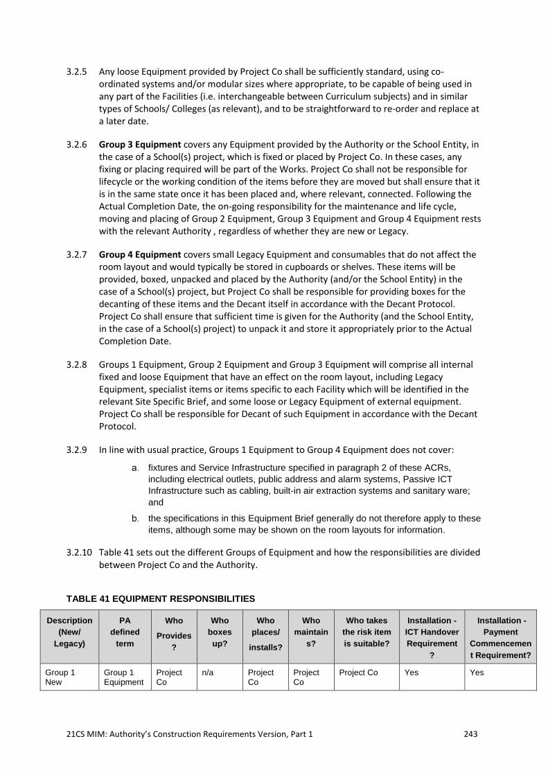
21CS MIM: Authority’s Construction Requirements Version, Part 1 243
3.2.5 Any loose Equipment provided by Project Co shall be sufficiently standard, using co-ordinated systems and/or modular sizes where appropriate, to be capable of being used in any part of the Facilities (i.e. interchangeable between Curriculum subjects) and in similar types of Schools/ Colleges (as relevant), and to be straightforward to re-order and replace at a later date.
3.2.6 Group 3 Equipment covers any Equipment provided by the Authority or the School Entity, in the case of a School(s) project, which is fixed or placed by Project Co. In these cases, any fixing or placing required will be part of the Works. Project Co shall not be responsible for lifecycle or the working condition of the items before they are moved but shall ensure that it is in the same state once it has been placed and, where relevant, connected. Following the Actual Completion Date, the on-going responsibility for the maintenance and life cycle, moving and placing of Group 2 Equipment, Group 3 Equipment and Group 4 Equipment rests with the relevant Authority , regardless of whether they are new or Legacy.
3.2.7 Group 4 Equipment covers small Legacy Equipment and consumables that do not affect the room layout and would typically be stored in cupboards or shelves. These items will be provided, boxed, unpacked and placed by the Authority (and/or the School Entity) in the case of a School(s) project, but Project Co shall be responsible for providing boxes for the decanting of these items and the Decant itself in accordance with the Decant Protocol. Project Co shall ensure that sufficient time is given for the Authority (and the School Entity, in the case of a School(s) project) to unpack it and store it appropriately prior to the Actual Completion Date.
3.2.8 Groups 1 Equipment, Group 2 Equipment and Group 3 Equipment will comprise all internal fixed and loose Equipment that have an effect on the room layout, including Legacy Equipment, specialist items or items specific to each Facility which will be identified in the relevant Site Specific Brief, and some loose or Legacy Equipment of external equipment. Project Co shall be responsible for Decant of such Equipment in accordance with the Decant Protocol.
3.2.9 In line with usual practice, Groups 1 Equipment to Group 4 Equipment does not cover:
fixtures and Service Infrastructure specified in paragraph 2 of these ACRs,
including electrical outlets, public address and alarm systems, Passive ICT
Infrastructure such as cabling, built-in air extraction systems and sanitary ware;
and
the specifications in this Equipment Brief generally do not therefore apply to these
items, although some may be shown on the room layouts for information.
3.2.10 Table 41 sets out the different Groups of Equipment and how the responsibilities are divided between Project Co and the Authority.
TABLE 41 EQUIPMENT RESPONSIBILITIES
Description
(New/
Legacy)
PA
defined
term
Who
Provides
?
Who
boxes
up?
Who
places/
installs?
Who
maintain
s?
Who takes
the risk item
is suitable?
Installation -
ICT Handover
Requirement
?
Installation -
Payment
Commencemen
t Requirement?
Group 1 New
Group 1 Equipment
Project Co
n/a Project Co
Project Co
Project Co Yes Yes
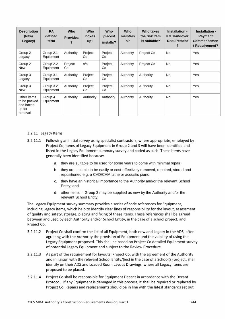
21CS MIM: Authority’s Construction Requirements Version, Part 1 244
Description
(New/
Legacy)
PA
defined
term
Who
Provides
?
Who
boxes
up?
Who
places/
installs?
Who
maintain
s?
Who takes
the risk item
is suitable?
Installation -
ICT Handover
Requirement
?
Installation -
Payment
Commencemen
t Requirement?
Group 2 Legacy
Group 2.1 Equipment
Authority Project Co
Project Co
Authority Project Co No Yes
Group 2 New
Group 2.2 Equipment
Project Co
n/a Project Co
Authority Project Co No Yes
Group 3 Legacy
Group 3.1 Equipment
Authority Project Co
Project Co
Authority Authority No Yes
Group 3 New
Group 3.2 Equipment
Authority Project Co
Project Co
Authority Authority No Yes
Other items to be packed and boxed up for removal
Group 4 Equipment
Authority Authority Authority Authority Authority No Yes
3.2.11 Legacy Items
3.2.11.1 Following an initial survey using specialist contractors, where appropriate, employed by Project Co, items of Legacy Equipment in Group 2 and 3 will have been identified and listed in the Legacy Equipment summary survey and coded as such. These items have generally been identified because:
they are suitable to be used for some years to come with minimal repair;
they are suitable to be easily or cost-effectively removed, repaired, stored and
repositioned e.g. a CAD/CAM lathe or acoustic piano;
they have an historical importance to the Authority and/or the relevant School
Entity; and
other items in Group 3 may be supplied as new by the Authority and/or the
relevant School Entity.
The Legacy Equipment survey summary provides a series of code references for Equipment, including Legacy items, which help to identify clear lines of responsibility for the layout, assessment of quality and safety, storage, placing and fixing of these items. These references shall be agreed between and used by each Authority and/or School Entity, in the case of a school project, and Project Co.
3.2.11.2 Project Co shall confirm the list of all Equipment, both new and Legacy in the ADS, after agreeing with the Authority the provision of Equipment and the viability of using the Legacy Equipment proposed. This shall be based on Project Co detailed Equipment survey of potential Legacy Equipment and subject to the Review Procedure.
3.2.11.3 As part of the requirement for layouts, Project Co, with the agreement of the Authority and in liaison with the relevant School Entity/(ies) in the case of a School(s) project, shall identify on their ADS and Loaded Room Layout Drawings where all Legacy items are proposed to be placed.
3.2.11.4 Project Co shall be responsible for Equipment Decant in accordance with the Decant Protocol. If any Equipment is damaged in this process, it shall be repaired or replaced by Project Co. Repairs and replacements should be in line with the latest standards set out
21CS MIM: Authority’s Construction Requirements Version, Part 1 245
below. For example, where tables and chairs need to be replaced they must meet the ergonomic standard EN1729, which may require all the others in the room to also be replaced to ensure size compatibility.
3.3 Equipment Provision
3.3.1 General Layout Requirements
3.3.1.1 Project Co’s Loaded Room Layout Drawings shall demonstrate that the General Teaching spaces and light Practical Teaching areas, in particular, will allow for short-term changes of layout and use.
3.3.1.2 Project Co shall illustrate how the requirements below have been met through an example Loaded Room Layout Drawings for each different type [or shape] of space in which:
Project Co is providing fittings or fitted Equipment in Groups 1 or 2 (such as those
in Secondary School Practical Teaching spaces); and
the proposed area or shape of a space differs from the area recommendations in
the ADS, to prove that the area is workable with the Equipment identified in the
Legacy Equipment survey summary, including Equipment in Group 3.
3.3.1.3 In spaces where Project Co is providing Equipment, there shall be co-ordination between the choice of loose and fixed furniture in terms of size, appearance and function. Where these spaces also have Group 3 items, Project Co shall ensure that any fixed items they provide suit the ’s Legacy Equipment.
3.3.1.4 Where Project Co is placing or fixing Legacy Equipment, all layouts shall address the following points:
Legacy Equipment shall be located appropriately in accordance with the
requirements in the relevant Site Specific Brief; and
Legacy Equipment shall be integrated with any new Equipment provided by
Project Co; and
where Legacy items are found to be unsuitable, for instance where they do not fit
or match the size and dimensions of the space to be provided in the Building,
Project Co shall make appropriate adjustments to the layout detailing the
adjustments.
3.3.1.5 Project Co shall ensure that all Equipment that is provided is capable of being laid out to:
create spaces which are not cramped or overcrowded for the maximum number
of pupils to be accommodated in the relevant area;
meet the needs of the School/ College’s Curriculum and suit the related activities
for each space or Suite of Spaces and the activities listed in the SoA and ADS;
allow a number of different layouts within each space type, to suit different
teaching styles and the educational objectives of each Facility;
where possible or required in the SSB, offer more than one teaching position;
ensure good sight lines to and from all Students in the space;
ensure that no-one is placed at a disadvantage and that all Students are able to
access all activities effectively and safely;
for disabled Students to be able to access all activities on offer in at least one
space of each type or within each suite;
21CS MIM: Authority’s Construction Requirements Version, Part 1 246
allow for safe movement by Students and easy access to fire escape routes, with
no fixed Equipment blocking exits;
where required, allow space for storing coats and bags near doors;
for Foundation Phase classrooms a low-level coat rain gear rack and a boot shelf
is to be provided near the door to the outside space to support free flow
movement between indoors and outdoors;
position equipment safely, away from Circulation areas or door swings;
fitted Equipment to be placed at 90° to windows to avoid glare, in ICT areas;
sufficient space for the safe operation of machinery and other equipment;
integrate with the Building, Service Infrastructure and the ICT Infrastructure;
ICT Equipment proposed for the room to be safely located with access to
appropriate power and data;
take account of the position of other Service Infrastructure and Building features
such as radiators and window sills;
allow Equipment to benefit from both natural and artificial lighting while avoiding
glare, particularly in ICT areas [where glare can be a major obstacle to effective
working];
enable central areas to be clear for moveable items by restricting Equipment to
the perimeter of the space where possible;
allow easy to supervision of equipment by placing them in one activity zone; and
allow sufficient space for the safe operation of machinery and other equipment.
3.3.1.6 Project Co shall use Loaded Room Layout Drawings to determine the optimum location of servicing outlets such as gas, power and water, and to ensure that these are safely positioned. In all spaces, the layouts shall illustrate that any ICT Equipment required can be accommodated.
3.3.1.7 Project Co shall ensure that at both the initial design layout stage and final specification of Equipment, consideration should be given to Students with SEN (D) by ensuring that:
where Equipment is adjustable for variable heights (within a range) it is easily and
discretely operable by the user; and
the appropriate size, colour, finish and height of Equipment is provided. For
example, for Students with visual impairment, the colour of furniture shall contrast
with the carpet and the chair.
3.3.1.8 The appropriate number and distribution of the following fittings are to be provided, as agreed with the Authority, and specified in the Facility specific ADS:
curtains and blinds;
shelves shall be fitted to all store rooms and storage areas sufficient for the
number and type of items to be stored therein;
fixed benching, with sinks as necessary, shall be provided to ICT –rich and
practical areas; and
noticeboards shall be fitted in corridors, teaching spaces and offices. Colour shall
preferably differ from tables.
3.3.2 Specific Equipment Requirements
21CS MIM: Authority’s Construction Requirements Version, Part 1 247
3.3.2.1 Where Project Co is responsible for the layout of Equipment, Project Co shall ensure that the following specific requirements are met, over and above those outlined in the relevant Site Specific Brief.
3.3.2.2 Defibrillators shall be provided in accordance with the UK Department for Education Guidance document (September 2018): Automated external defibrillators in schools.
3.3.2.3 In large General Teaching rooms, Project Co shall ensure that the choice and layout of Equipment shall provide:
adequate storage for Learning Resources in furniture, over and above storage in
store rooms;
at least one position for a wheelchair user, sited in such a way as to achieve a
direct view of at least the main teaching position, in at least one space of each
type or in each suite; and
furniture that is sufficiently lightweight to allow for short-term changes of layout
and use.
3.3.2.4 In Practical and Vocational Teaching spaces, Project Co shall ensure that:
safe working distances around Equipment are provided, as identified in relevant
best practice guidance;
where Equipment is serviced with water or gas, master controls are provided;
light Practical Teaching spaces are suitable to be used safely as registration
bases;
sinks are positioned to avoid congestion when used by a number of Students;
specialist fitters fit any specialist equipment, for example suppliers of service
pedestals in science laboratories;
the serviced system in a laboratory is suitable for the size and shape of the
proposed science space, its service arrangement and the priorities of the School /
College (as identified in the relevant Site Specific Brief);
the serviced system in heavy practical or vocational spaces ensure that
Equipment layouts take account of recommended safe operating zones for
respective pieces of equipment. Suitable ventilation and extraction is provided
and shut off valves where required;
in art rooms the positions of workstations maximise the use of natural light, and
the colours and finishes of fixtures and furniture reflect light without causing glare;
and
any rooms provided for art shall have space for both horizontal and vertical
display of two- and three-dimensional work;
solid work surfaces shall be provided in D&T spaces, art rooms, science teaching
spaces and science preparation spaces and shall be no less than 16mm thick.
Drainage grooves around sink areas shall be machined into the worktop material.
Tops of science pedestal units shall be firmly secured to the base unit with a
minimum of 8 fixing points.
3.3.2.5 In Halls and Performance Spaces, Project Co shall ensure that:
a number of assembly and performance options are possible for the given seating
capacity using generic furniture and any bleacher or fixed seating provided,
allowing for access and circulation;
21CS MIM: Authority’s Construction Requirements Version, Part 1 248
specialist suppliers shall be consulted on the most appropriate location of any
new audio-visual equipment;
specialist suppliers are consulted on the most appropriate equipment
specification and fixing method, including stage lighting bars and lanterns;
any Legacy Equipment such as lanterns, control equipment and scaffolding, and
Group 1 Equipment such as stage lighting bars shall be fixed by a specialist
supplier;
where it is the responsibility of Project Co to provide them, chairs in the main hall
should be stackable, with the maximum number calculated to determine storage
space. There shall be sufficient storage for examination tables, flats and staging
when not in use;
there is space to manoeuvre chairs, examination tables and staging when not in
use; and
in a Performance Space curtains form a proscenium arch and do not block
entrances and fire exits, and good sight lines are available from the audience.
3.3.2.6 In Secondary School halls only, (unless otherwise required y these ACRs) the main hall shall be provided with retractable bleacher seating at one end and a floor-level performance area at the other.
3.3.2.7 The Performance Space shall be the full width of the hall, accessed from doors at either side of the end wall at the appropriate height. The end wall shall be behind the performance area and suitable as a cyclorama. The minimum Performance Space area, for assemblies, shall be 1.5m deep if floor-based or 2.4m deep if provided on a stage. The maximum Performance Space area, for major performances, shall be at least 6.9m deep.
3.3.2.8 Bleacher seating shall be retractable and extend to approximately half of the length of the hall and, wherever possible, the full width of the hall, with minimal gaps at each side. It shall be electronically operated by a hand-held control and, when retracted, fit within the storage area for retractable bleacher seating identified in the SoA, at the back of the hall. It shall be positioned according to advice from a specialist supplier. The bleacher seating shall be provided with back support to the seats.
3.3.2.9 Where a raised stage is used, it shall provide the minimum Performance Space area described above on a permanent stage, with stair and disabled access (for instance through a platform lift) provided to access the doors in the end wall Project Co shall provide sufficient demountable staging to extend the stage to accommodate the maximum Performance Space area (or other staging options), steps to the front of the stage, and sufficient loose chairs to provide seating to the remainder of the hall, with aisles and a 1.8m gap between the front row and the stage. The staging shall be chosen to be easily stored, with the chairs, within the furniture store identified in the SoA, which shall open directly off the hall.
3.3.2.10 In Dining and Social areas, where new Equipment is provided Project Co shall ensure that the layout, demonstrated with a flow diagram, is produced by a specialist catering company or consultant and shall allow for:
a logical flow of Students round the Dining and Social space from arrival, queuing
to collect food, both hot and cold, eating and self-clearing based on the number of
lunch sessions, the number of pay stations (where relevant) and the hot/cold split,
as outlined in these ACRs;
space is provided for food vending trolleys and dirty/ waste collection points;
21CS MIM: Authority’s Construction Requirements Version, Part 1 249
sufficient circulation area between dining tables to enable pupils to leave their
positions easily and others to access them;
sufficient space between tables so that chair legs can be seen;
sufficient circulation to allow a wheelchair user to access some tables and dine
alongside other Students;
the servery is designed to have an efficient serving area layout, whether use fixed
or moveable Equipment;
servery design should identify menus and products for sale, whilst minimising the
potential for theft;
the servery has a tray slide and supports to ensure an efficient service and
Students’ safety;
there is an efficient layout with adequate seating capacity for the allocated
amount of time for lunch or other specified periods, acceptable eating times and
the number of Students, as specified in the relevant Site Specific Briefs;
provides seating capacity for Students who bring their own lunch to eat in the
Dining and Social room;
provision of storage furniture with sufficient space around it, as defined in these
ACRs; and
where the design requires storage of outdoor coats or bags near the Dining and
Social area, storage furniture with sufficient space around it shall be provided.
3.3.2.11 In Kitchens Project Co shall ensure that the Equipment and the associated Loaded Room
Layout Drawings provides:
catering equipment necessary for the preparation of hot and cold meals in a cost
effective and efficient manner both in terms of staffing and energy use to allow
the School/ College to deliver the number of meals in accordance with the
preparation model, at the frequencies specified in these ACRs;
a functional layout that allows for efficient operations and any special dietary
requirements, by arranging the main activity areas of delivery, unpacking,
storage, preparation, cooking and wash-up in a logical sequence to ease work
flows;
a sensible ‘flow’ from the self-clearing facility to the Kitchen pre-clean area and
dish wash, and from dishwasher to crockery/cutlery/tray storage; and
high efficiency kitchen equipment, to achieve the good practice benchmarks for
energy usage for schools given in CIBSE TM50 ‘Energy Efficiency in Commercial
Kitchens’, 2009.
3.3.2.12 In all Secondary School and College Learning Resource Areas/Libraries along with any specific requirements within these ACRs, Project Co shall employ a library specialist to design the layout to provide:
the most efficient use of the space;
furniture, particularly shelving units, positioned to allow sight lines from the
librarian’s desk, where provided, to all parts of the library;
flexibility to take on board different uses of the space in the future; and
low shelving or seating positioned near windows in such away so as to maximise
natural lighting.
3.3.2.13 In SEN (D) support areas, Project Co shall ensure that the choice and layout of the Equipment shall contribute to a calming environment. Storerooms shall have enough
21CS MIM: Authority’s Construction Requirements Version, Part 1 250
clear space for any specialist equipment which may be needed, including both Teaching Resources and aids for Students with physical disabilities. These ACRs shall state the assumptions to be made in Specially Resourced Provision or Designated Units as to the typical number of mobility aids per Student that will require storage. Where these have additional design requirements, these are given in the relevant Site Specific Brief and the SoA.
3.3.2.14 In store rooms, Project Co shall ensure that shelves are provided and fitted with sufficient area and depth for the number and type of items to be stored therein, with sufficient space in front to allow reasonable access.
3.3.2.15 Project Co shall ensure that personal storage, including Student lockers and other appropriate storage for coats and bags shall be sufficient for the number of pupils at each School, in line with the SoA and the relevant Site Specific Brief. Where provided, Project Co shall ensure that:
where coats and bags are placed in the Classroom (usually in Primary Schools)
sufficient and suitably positioned storage space is provided for coats and bags,
over and above the required area of the Classroom;
lockers are not placed alongside guarding or balustrades, do not restrict
movement along main Circulation routes when being used and are not congested
by creating banks of multiple units;
layouts allow sufficient space between lockers for safe use;
lockers are located to avoid long travelling distances between lessons, which can
prevent usage;
banks of multiple lockers are avoided to prevent congestion;
lockers above 1.2m high are fixed back to the wall; and
lockers are secured by the School/College’s preferred method, e.g. combination
locks, as defined in these ACRs.
3.3.2.16 In PE changing rooms Project Co shall carefully plan Equipment in changing rooms to provide comfortable and safe conditions for pupils, with sufficient distances between lockers and benches.
3.3.2.17 Noticeboards in Circulation areas shall be fitted to satisfy the requirement of BB100 such that they are not more than 3m wide and have a gap between them of at least 1m. In protected corridors (those used for means of escape) they should also be fitted with a cover, preferably top hung.
3.3.3 Service Infrastructure within Equipment
3.3.3.1 Project Co shall ensure that all serviced Equipment is integrated with the electric lighting, power and other systems in the Building, and it shall be clear where the responsibility lies for the various fitting and connections in each case.
3.3.3.2 Project Co shall ensure that all equipment addresses the following points to provide an integrated and responsive system of mechanical, electrical, protective and communication installation:
all Service Infrastructure and installations meet the relevant standards as outlined
in these ACRs;
21CS MIM: Authority’s Construction Requirements Version, Part 1 251
pipe-work or cables are easily accessible for maintenance (but hidden from view
wherever possible), do not provide dust traps, and are protected from potential
damage (including Malicious Damage);
any connections, distribution systems, components and containment systems
within Equipment are safely protected, tamper-proof, correctly insulated, and free
from exposed contacts and clearly labelled;
specialist suppliers install serviced equipment, whether new or Legacy;
all user controls on equipment and used by Students are comprehensible and
accessible;
all controls are securely fixed to the item of Equipment or the internal fabric of the
Building (i.e. not remote controls) and do not rely upon batteries for power;
controls such as isolator switches on Equipment only enable use by authorised
personnel;
all Equipment incorporating water and drainage (such as serviced appliances in
D&T workshops, food rooms and science laboratories) is installed so as to ensure
hygienic conditions and the effective disposal of waste water;
socket outlets are positioned away from sinks to reduce the risk of electrically
powered equipment being placed in water, as defined in these ACRs; and
in food rooms, socket outlets are positioned to ensure that an electrical cable
attached to a piece of equipment does not have to cross a hot cooking surface.
3.3.4 Integration with ICT
3.3.4.1 Project Co shall comply with its obligations in a way that is compatible with the Authorities ICT solution as outlined in the relevant Site Specific Brief and ICT Solution Summary, e.g. the cabling requirements of user devices and the link between technology and specialist equipment e.g. CAD CAM systems will be taken into account when designing the Building and producing the Loaded Room Layout Drawings.
3.3.4.2 Where furniture is used that has not been designed to accommodate computer equipment, Project Co shall ensure that there is adequate space for comfortable and safe use of the technology and where appropriate, cable management.
3.3.4.3 Other than in the case of Lifecycle Assets, Project Co may wish to make use of suitable Legacy Equipment if it is available.
3.3.5 Blinds and Curtains
3.3.5.1 Blinds and/ or curtains shall be provided in the following situations and in line with the Facility Specific ADS and any additional requirements of these ACRs:
blinds to exterior glazing and rooflights for solar glare and daylight control;
roller blinds to exterior glazing in science laboratories and science studios for dim-
out during science experiments;
blinds or curtains to exterior glazing for dim-out in Performance Spaces;
blinds or curtains to internal glazing for dim-out;
blinds to internal glazing where privacy is required;
in a Secondary School or College, curtains to form a proscenium arch at the front
of the maximum performance area in a hall; and
shower curtains in changing rooms.
21CS MIM: Authority’s Construction Requirements Version, Part 1 252
3.3.6 Wayfinding and Signage
3.3.6.1 The wayfinding system shall be designed to guide visitors from the Site boundary to an individual room, displaying only the level of information required at each decision point.
3.3.6.2 Signs shall be of a uniform type and be positioned in a similar manner throughout
3.3.6.3 Project Co shall provide a main site entrance sign and external directional signage to provide guidance for wayfinding by pedestrians and vehicles, especially for visitors, in directing them from the site entrance (via visitor parking if arriving by car) to the main reception. Any main site entrance sign provided shall detail the name of the School or College and other pertinent information. The sign shall be of a design that allows for the incorporation of changes when necessary and gives a positive first impression, written in both Welsh and English. The sign shall be illuminated and of a design that allows for the incorporation of changes when necessary.
3.3.6.4 As people move around the site signs shall give clear indications of directions for all Facility Users, including those new to the Facility, and shall define the purpose of the Buildings, providing reassurance and confirmation that they are moving in the right direction. There shall be signs to clearly identify assembly points, public and staff parking, externally accessed stores and plant rooms, delivery routes, restrictions and limitations, warnings and hazards etc.
3.3.6.5 Project Co shall provide internal directional signage from the main Building entrances and arrival points at each level (including at lifts and stairs) to provide guidance for internal wayfinding. These will inform people of which Department (in the case of Secondary Schools and Colleges, room, facility etc. is on each floor, as well as informing them which floor they are currently on. There shall also be room numbering provided in logical blocks, using the Building layout and architecture to provide suitable sequenced areas
3.3.6.6 Project Co shall fully integrate signage into the design of the Buildings and provide signs for every room and space, as described in the ADS denoting its name or purpose and agreed numbering, and to denote Suites of Spaces, such as faculties or Departments.
3.3.6.7 Project Co shall provide signage that is consistent and clearly visible, especially for visitors in directing them from Facility entrance to its main reception. It should also be capable of alteration where appropriate, without being easily tampered with.
3.3.6.8 Any external building signage to main entrances (either façade or canopy mounted) shall be clearly visible.
3.3.6.9 Sign surfaces shall be sufficiently hard to resist impacts from hand-held objects without any noticeable change to the surface appearance. Surfaces shall also resist abrasion from cleaning methods and maintenance systems without any noticeable change in surface appearance. All fixings used shall be suitable for their intended purpose and shall be in accordance with the manufacturer's recommendations.
3.3.6.10 Project Co shall comply with any specific requirements of the relevant Site Specific Brief.
3.3.7 External fittings
3.3.7.1 Project Co shall provide external fittings and Equipment that are:
safe for children and young people;
manufactured from durable materials;
suitable for different ages and physical abilities; and
21CS MIM: Authority’s Construction Requirements Version, Part 1 253
chosen to allow a number of layouts and easy rearrangements, including
movement over distances (for example moving rugby posts to storage at the
close of season), but sufficiently robust to withstand rigorous use.
3.4 Equipment Performance and Quality
3.4.1.1 Project Co shall ensure that all Equipment provided satisfies the quality and performance requirements specified below and within these ACRs to ensure it is safe and fit for purpose.
3.4.1.2 Project Co shall ensure that:
all Equipment materials provided by Project Co are fit for purpose and comply
with Welsh, British and European Standards and further with any such Welsh,
British and European Standards that are in force or not in force but published at
the time of the date of this Agreeement;
certificates and reports of tests carried out shall be seen and stored;
if a third party is buying Equipment then they must also be able to produce valid
test certificates;
any new Equipment is ergonomically designed to ensure comfortable use and to
meet the needs of different ages and physical abilities;
new Equipment does not have any sharp edges or corners that may cause injury
and chairs are designed so that legs do not protrude beyond the top of the back
or present a tripping hazard; and
where furniture screens are provided, they are stable with a suitable mechanism
for fixing together, lightweight enough to be re-organised quickly and easily and
do not present a tripping hazard.
3.4.1.3 Practical and Vocational spaces furniture shall:
meet the service requirements in the ADS;
allow Students to carry out practical activities individually, in pairs and in small
groups;
have sufficient flexibility to allow whole class discussion and presentation; and
allow all Students to be able to face the demonstration bench or
teaching/presentation wall and be observed by the teacher.
3.4.1.4 In order to accommodate disabled Students and those with SEN (D), Project Co shall ensure that the appropriate size, colour, finish and height of Equipment is provided. Where Equipment is adjustable for variable heights it shall be easily and discretely operable by the user.
3.4.2 Ergonomics, Strength and Stability
3.4.2.1 Project Co shall ensure that:
any new Equipment is ergonomically designed to ensure comfortable use;
all new tables and chairs to be used by pupils must comply with the ergonomic
European Standard EN1729, which also covers strength and stability. This will
therefore be an assurance of ergonomic suitability as well as quality and fitness
for purpose;
21CS MIM: Authority’s Construction Requirements Version, Part 1 254
storage should comply with BS 587364; and
the dimensions of furniture and fittings are agreed with the Authority, to ensure
the correct specification for the age and size range in the space.
3.4.2.2 All new and Legacy Equipment shall:
be durable and allow for a variety of postures and activities;
be safe, strong, stable and durable;
not have any sharp edges or corners that may cause injury;
have chair legs that do not protrude so far as to present a tripping hazard; and
where furniture screens are used, they are stable with a suitable mechanism for
fixing together. They should also be lightweight enough to be re-organised quickly
and easily and not present a tripping hazard.
3.4.2.3 Project Co shall identify the availability and, where applicable, the length of guarantees and/or warranties.
3.4.3 Fabric and Materials
3.4.3.1 Project Co shall ensure that the design and specification of fabric and materials of all Equipment provided by Project Co is fire resistant, fit for purpose and carefully detailed and compliant with the ADS. The colour, texture and finish of materials shall be deployed in a considered way, particularly for those pupils with SEN (D). Contrasts of colour should be used for pupils with visual impairment.
3.4.3.2 Project Co shall ensure that the finish chosen is appropriate for the activities taking place in the room.
3.4.3.3 Various finishes and applications are available for edgings of table and storage tops. Project Co shall ensure that edging materials are robust and are not susceptible to misuse.
3.4.3.4 Complicated corners, edges and frames that can trap food should be avoided for dining tables.
3.4.3.5 Project Co shall ensure that all fittings and furniture in music spaces shall include sound absorbent materials necessary to meet the acoustic requirements of that space.
3.4.3.6 Project Co shall ensure that all Equipment provided is to be manufactured to prevent ‘off-gassing’ pollutants like volatile organic compounds (VOC). Equipment is to contain low VOC materials65, and to be assembled and maintained with the use of low VOC materials, including, cabling, paints and adhesives.
3.4.3.7 Project Co shall ensure that fire resistance is compliant with current Welsh, British and European Standards and with any that are known to be due to come into force. This is particularly important where a high volume of furniture will be stacked and stored. Upholstered furniture shall meet the relevant Welsh, British and European standards particularly for flammability, strength and stability (usually general contract) and fabric wear and tear in order to be re-used in a different setting.
3.4.4 Services
64 BS 5873-4: 1998: Educational furniture. Specification for strength and stability of storage furniture. 65 Levels of VOC not exceeding 300µg/m³ averaged over 8 hours.
21CS MIM: Authority’s Construction Requirements Version, Part 1 255
3.4.4.1 Project Co shall ensure that all serviced Equipment shall be integrated with the artificial lighting, power and other systems in the Building, and it shall be clear where the responsibility lies for the various fitting and connections in each case.
3.4.5 Serviced Equipment
3.4.5.1 Project Co shall ensure that all equipment provided addresses the following points to provide an integrated and responsive system of mechanical, electrical, protective and communication installation:
any pipe-work or cables shall be easily accessible for maintenance but, wherever
possible, hidden from view, not forming dust traps and made tamper-proof; and
any connections, distribution systems, components and containment systems
within Equipment shall be safely protected, tamper-proof, correctly insulated, and
free from exposed contacts and clearly labelled.
3.4.5.2 Project Co shall ensure that specialist suppliers shall install the relevant equipment, either new or Legacy;
3.4.5.3 Project Co shall ensure that Facility Users shall have control over the equipment provided. All user controls on equipment provided by the Project Co shall be comprehensible, accessible and quietly responsive;
3.4.5.4 Controls such as isolator switches may need to be located on walls or fixed furniture to allow use by authorised personnel only.
3.4.6 Water and Drainage
3.4.6.1 Project Co shall ensure that all Equipment incorporating water and drainage (such as serviced appliances in workshops, food rooms and science laboratories) is installed so as to ensure hygienic conditions and the effective disposal of waste water, surface water and all liquid waste from the Facility and its activities.
3.4.6.2 Where sinks are to be supplied and installed by specialist furniture manufacturers, such as science laboratory manufacturers/suppliers, Project Co shall ensure coordination between the Equipment and Building Elements.
3.4.7 Gas and Compressed Air
3.4.7.1 Project Co shall install any gas and compressed air installations and appliances in accordance with appropriate regulations and guidance.
3.5 Equipment Life and Procurement
3.5.1 Design Life and Maintenance
3.5.1.1 The structure of all operable furniture provided by Project Co shall be compliant with all statutory regulations related to maintenance and management as well as provision.
3.5.1.2 All Equipment provided shall be easily cleaned and maintained and all materials and components shall have a suitable design life to ensure minimum inconvenience and disruption from breakdowns, repairs and maintenance activities.
3.5.1.3 Project Co shall ensure that all Equipment is:
durable and reasonably easy to maintain;
simple in construction, to reduce maintenance and replacement costs;
easy to operate where adjustable (but difficult to misuse), repair or replace;
21CS MIM: Authority’s Construction Requirements Version, Part 1 256
housed in such a way that it is easy to access or remove for maintenance
purposes; and
all relevant staff and Facility Users shall be provided with adequate training in the
use and maintenance of Equipment provided by Project Co, where necessary.
3.5.2 Warranties
3.5.2.1 Warranties will be provided in accordance with the requirements of the Agreement including Appendix B (Completion Criteria) of Schedule 10 (Outline Commissioning Programme) .
3.5.3 Purchasing and delivery
3.5.3.1 Project Co shall:
Agree a Loose Equipment Purchase Protocol with the Authority which will form
part of the Project Co’s Proposals. The protocol shall set out how the
procurement of loose Equipment will be co-ordinated between the Authority, the
School and Project Co, what Loose Equipment will be procured by the Authority
and what by Project Co and all associated arrangements and programme;
submit a schedule in the Project Co’s Proposals listing all new and Legacy fixed
and loose Equipment that it is responsible for;
be responsible for the supply of new Equipment, and the delivery and fixing of all
fixed Equipment as detailed in the Project Co’s Proposals;
be responsible for the supply, delivery and placing of all loose Equipment detailed
on the schedules;
liaise with suppliers to ensure ordering of new Equipment is in accordance with
the required specification;
liaise with suppliers to ensure delivery of Equipment is not before the Building is
ready to receive it;
liaise with each Authority (and each relevant School Entity, in the case of a
School(s) project), to ensure Legacy items are securely stored for the duration of
time they are not in use and are transported to the new site/block when the
Building is ready;
when necessary, ensure that Legacy Equipment is stored and/or moved
appropriately, unless the Authority, has agreed to take responsibility for the
serviceability and temporary storage of any item; and
ensure a minimum number of delivery times where the Project Co is responsible
for ordering Equipment.
21CS MIM: Authority’s Construction Requirements Version, Part 1 257
4. ICT Design Requirements
4.1 Project Co shall deliver the requirements set out in these ACRs relating to the provision of ICT Infrastructure such that the ICT Infrastructure is capable of delivering the Authority’s ICT solution.
4.2 Project Co shall ensure that the ICT Solution Summary aligns with the operational requirements of the school/college.
4.2.1 Introduction
4.2.2 This section and ‘The ICT Responsibilities Matrix’, set out the scope and the requirements of the ICT Equipment included within the Works and provide a baseline for responsibilities.
4.2.3 The aim of this section is to elaborate upon ‘the ICT Responsibilities Matrix’ and to clarify the requirements for the ICT Equipment elements of the building design and Works. School or College-specific information, for example the type of Initial ICT Equipment that will be transferred, is contained within the ICT Solution Summary. Read together, these will provide sufficient information to develop proposals. Project Co should also refer to the other sections in these ACRs.
4.2.4 Project Co will provide new infrastructure, initial training, AV installation and the Decant of Initial ICT Equipment.
4.2.5 Network Infrastructure security
4.2.5.1 Project Co. shall provide a secure wired and wireless environment by:
configuring the wired and wireless infrastructure to support network segregation,
security and quality of service (QoS); this shall not impact on the network’s
deployment or performance and shall be aligned with the school environment and
GDPR guidance. Project Co. shall provide a rationale for how this will be
achieved specific to the School’s requirements;
implementing network access controls and policy management that ensure
authorised mobile user devices and/or guest user roles are securely
authenticated onto the network, and that network traffic is protected from external
and unauthorised internal interception, as per GDPR guidance. Project Co. shall
detail how this will be achieved.
4.2.6 ICT Infrastructure means:
Passive ICT Infrastructure - cabling infrastructure for data and voice services,
including data outlets, containment, patch panels and cabinets;
Active ICT Infrastructure – core and edge network switches and associated
network switches and routers, including support for Power over Ethernet and
wireless Active Equipment – controllers and access points for an enterprise
whole-site wireless network;
Telephony – an enterprise level, VOIP telephony solution including core
equipment and handsets, and incoming connectivity; and
Internet provision – the provision or relocation of a broadband internet
connection.
4.2.7 The layout of ‘The ICT Responsibilities Matrix’ lists the following as major ‘aspects’ of ICT systems in Facilities:
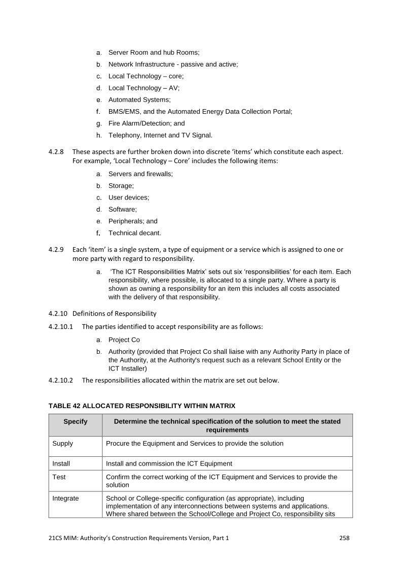
21CS MIM: Authority’s Construction Requirements Version, Part 1 258
Server Room and hub Rooms;
Network Infrastructure - passive and active;
Local Technology – core;
Local Technology – AV;
Automated Systems;
BMS/EMS, and the Automated Energy Data Collection Portal;
Fire Alarm/Detection; and
Telephony, Internet and TV Signal.
4.2.8 These aspects are further broken down into discrete ‘items’ which constitute each aspect. For example, ‘Local Technology – Core’ includes the following items:
Servers and firewalls;
Storage;
User devices;
Software;
Peripherals; and
Technical decant.
4.2.9 Each ‘item’ is a single system, a type of equipment or a service which is assigned to one or more party with regard to responsibility.
‘The ICT Responsibilities Matrix’ sets out six ‘responsibilities’ for each item. Each
responsibility, where possible, is allocated to a single party. Where a party is
shown as owning a responsibility for an item this includes all costs associated
with the delivery of that responsibility.
4.2.10 Definitions of Responsibility
4.2.10.1 The parties identified to accept responsibility are as follows:
Project Co
Authority (provided that Project Co shall liaise with any Authority Party in place of
the Authority, at the Authority's request such as a relevant School Entity or the
ICT Installer)
4.2.10.2 The responsibilities allocated within the matrix are set out below.
TABLE 42 ALLOCATED RESPONSIBILITY WITHIN MATRIX
Specify Determine the technical specification of the solution to meet the stated
requirements
Supply Procure the Equipment and Services to provide the solution
Install Install and commission the ICT Equipment
Test Confirm the correct working of the ICT Equipment and Services to provide the solution
Integrate School or College-specific configuration (as appropriate), including implementation of any interconnections between systems and applications. Where shared between the School/College and Project Co, responsibility sits
21CS MIM: Authority’s Construction Requirements Version, Part 1 259
with the School/College, but Project Co will provide support including limited resources. The package of support provided by Project Co is detailed in paragraph 4.12 below and the relevant Site Specific Brief.
Maintain Provide day-to-day management, repair and replacement of the ICT Equipment and Services throughout a contracted period.
4.2.11 Responsibility Matrix Line Items
4.2.11.1 The technical standards outlined in this section are minimum standards. Where standards change (for example, wireless technology) Project Co is expected to conform to the latest ratified and accepted standard as described below.
4.2.11.2 Project Co is expected to deliver the requirements as specified in ‘The ICT Responsibilities Matrix’ and the following sections provide additional detail with regard to each item in that matrix.
4.3 Server Room and Hub Rooms
4.3.1 Project Co shall provide a dedicated and secure environment and space to house infrastructure and server equipment, to include but not be limited to: cabinets holding servers and associated storage and backup equipment, core switches, edge switches, wireless controllers, telephony systems, cable distribution and distribution points and terminating equipment and presentation for broadband and telephone lines, and for connections to additional hub rooms containing supplementary equipment, such as edge switches, as required.
4.3.2 The server room and hub rooms shall be designed to safely and effectively accommodate the cabinets required by the installed equipment, both new and decanted, located around the Building to create an effective network topology.
4.3.3 When the size of a Building permits Project Co may use a single central space to house all server and infrastructure equipment without the need for separate hub rooms.
4.3.4 The server room and hub rooms shall be of sufficient size to allow, as a minimum:
adequate Circulation space for service and maintenance activities to be
performed without moving any cabinets; and
all cabinets to be accessible from front and rear with enough space for the
cabinet doors to open fully when the door(s) to the room are closed, with a
minimum clearance of 1200mm between the contents of the cabinet and wall.
4.3.5 Server rooms and hub rooms shall be designed to meet the requirements of these ACRs.
4.3.6 Connections to existing Buildings will be re-provided using the infrastructure standards covered in this document.
4.3.7 The location of the server and hub rooms shall ensure that Service Infrastructure not supplying the server room are not routed through, above, or on adjacent walls to the room.
4.3.8 Project Co shall provide that the server room as the termination point for any Internet and communications service to the Facility and any rooftop aerial or satellite dish for receiving digital broadcast transmissions.
21CS MIM: Authority’s Construction Requirements Version, Part 1 260
4.3.9 The dimensions of the spaces provided shall be sufficient to accommodate the equipment being installed and to allow adequate circulation space for service and maintenance activities to be performed. Access for any envisaged maintenance purpose must be possible without moving the rack system.
4.3.10 The server rooms and distribution rooms should be located so that they are not below or sharing a party wall with wet Service Infrastructure and to ensure that the possibility of damage or contamination due to failures in any Service Infrastructure is minimised. Server and hub rooms shall not be adjacent to or below rooms with water services, including but not limited to toilets, bathrooms, wet areas. Project Co. shall ensure their design shall prevent flooding of the server room from adjacent and other spaces. The location of the server room shall be such that it is not susceptible to flooding from internal as well as external forces. No Service Infrastructure should traverse server or hub rooms. Server rooms shall not be located on the roof or below ground level. Where such issues are encountered and require mitigating and/or the size of the building service results in copper cabling runs exceeding 90m, separate hub rooms will be required.
4.3.11 All service and delivery access routes to the server and distribution rooms must be designed to allow easy movement and installation of equipment and fittings without dismantling large items. If doors open into the server/hub room they must allow cabinet doors to open at the same time. Access to the room(s) should not be from a classroom.
4.3.12 Project Co shall ensure that the server room is the termination point for any Internet and telecommunications services to the Facility and any rooftop aerial or satellite dish for receiving digital broadcast transmissions, as described in the School or College-specific ICT Solution Summary.
4.3.13 Project Co shall meet the requirements of the ICT Responsibilities Matrix including offering in its solution the following:
Project Co shall provide a dedicated clean power supply to enable the server
room supply to be left running while power in other sections of the Building is
switched off; and
the power supply should be sufficient to support the equipment planned to be
housed within the server and hub rooms together with headroom for future
expansion.
4.3.14 Project Co shall provide power distribution units to support all Active Infrastructure, servers and associated components.
4.3.15 Project Co shall provide an accessible socket outlet adjacent to each cabinet, of a rating appropriate to the respective load, for example 1 x 32A for each server/core equipment cabinet and 1 x 16A for each edge switch cabinet
4.3.16 Project Co shall provide server and data cabinet surge protection to prevent damage to sensitive equipment
4.3.17 With regards to UPS Project Co shall ensure that the following requirements are met:
Uninterruptible Power Supply(s) (UPS) are provided in the form of a rack-
mounted battery system that will provide the following with 30 minutes autonomy,
as a minimum and capable of providing transient over voltage protection;
servers and associated storage and backup systems;
21CS MIM: Authority’s Construction Requirements Version, Part 1 261
core switches;
wireless controllers;
broadband terminating equipment and/or routers;
core telephony equipment and/or routers;
the rating of the UPS is compatible with the load, the connecting cable(s) and the
power supply it is connected to;
relevant software is provided to enable a controlled shutdown (if required), with
notification for all Servers, within the available runtime of the UPS battery(s);
UPS shall comply with BS EN 62040-1 and BS EN 62040-3 (and any updates or
replacements). Project Co shall ensure that the mode of operation shall be on-line;
the UPS shall be compatible with the load; and
batteries are integral to the UPS enclosure, have an autonomy of 30 minutes, are lead-
acid valve regulated (VRLA) to BS EN 60896-21 and BS EN 61056-1 (and any
updates or replacements), and have a minimum service life of 8 years.
4.3.18 ICT Server Room and Hub Room Ventilation
4.3.18.1 Refer to section 2.9.48
4.3.19 Sprinkler Systems
4.3.19.1 Sprinkler system requirements are included in 2.12.6 of these ACRs. Alternative fire suppressant systems for server and hub rooms are to be provided where identified in these ACRs.
4.3.20 Server Room and Hub Room Furniture
4.3.20.1 Project Co shall provide sufficient server racks of appropriate dimensions to house the servers that form part of the ICT Equipment. Racking design should support the cooling strategy of the room and should incorporate sufficient space and ancillary items so that a good standard of patching cable management can be achieved. Project Co may use Legacy ICT Equipment if available racking design should support the cooling strategy of the room.
4.3.20.2 Project Co shall provide sufficient cabinets to house patch panels for copper and fibre termination and Active network distribution equipment, for example core and edge switching. Racking design should support the cooling strategy of the room. Project Co may use Legacy ICT Equipment if available.
4.3.20.3 Project Co shall provide patch panels for data, telephony and fibre distribution to complete the network topology. All outlets should be appropriately labelled.
4.3.20.4 Project Co shall provide patch leads consistent with cabling standards and warranty to complete the network topology. The patch leads should reflect the Authority specific requirements for any colour scheme so as to support the Authority and each School Entity in any on-going maintenance and support, as detailed in these ACRs. Project Co may use Legacy patch leads if available, subject to not invalidating the warranty for any new cabling
4.3.20.5 Project Co shall provide service containment and routing in the form of dado, tray, riser and basket containment to match the cable specification and design aesthetics required. In order to provide redundancy there should be two separate, independent fibre routes linking each hub room to the server room.
21CS MIM: Authority’s Construction Requirements Version, Part 1 262
4.3.20.6 Project Co shall provide server room/distribution cabinets, ICT Equipment (including the ICT Infrastructure)required by the Works or Services.
4.3.20.7 Project Co shall provide anti-static flooring in server rooms and all extraneous metal parts including door frames in server rooms shall be electrically earth bonded. Project Co shall ensure that raised floors and floor surfaces in server rooms shall be low smoke and zero halogen type.
4.4 ICT Network infrastructure - Passive
4.4.1 Project Co shall provide wired infrastructure (cables, ducting, containment, routing, termination, patch and fly leads and presentation) including the passive data cabling for the ICT network and wireless network and integrated systems which rely on data connections to function, for example, cashless catering systems, digital signage, telephony, internal and external CCTV, BMS, EMS, and the Automated Energy Data Collection Portal, etc.
4.4.2 Project Co shall ensure that where fibre cabling is used:
the installation conforms to the relevant sections within the TIA/EIA 568 standards
for the type of cable being installed, and that manufacturers instructions for
handling and installation of cables are fully adhered to;
links between cabinets should have two separate fibre cables for resilience. It is
conformant 16 core multi-mode OM4 (50/125) fibre as a minimum, with different
routes back to the server room to ensure that both cannot be severed at the
same, with all cores presented for use to support future requirements and
resilience;
the maximum length of the fibre is 400m, and this is separately contained to avoid
interference, with a bend radius controlled in line with the specification of the
cable manufacturer;
where fibre is over 400m an appropriate specification of fibre is used to support
the dependent Active infrastructure;
fibre warning labels should be attached along the length of the cable at 3m
intervals;
sufficient slack (3m+) should be left at each end of the cable to facilitate re-
termination or relocation;
no intermediate splices are used in the cable runs;
a minimum 20-year manufacturer’s warranty is provided for the complete cabling
system;
test results are provided for the performance of and length of 100% of the cables
that have been installed; and
all relevant documentation is handed over to the Authority , including network
topology details, cabling test results, cabling test certificates, cabling warranty
information including evidence of installer accreditation, and other network
documentation.
4.4.3 Project Co shall ensure that where copper cabling is used:
the installation conforms to the relevant sections within the TIA/EIA 568 standards
for the type of cable being installed;
it should be Category 6A (Cat 6A.) standard as a minimum, with all terminations
following the manufacturer installation guidelines;
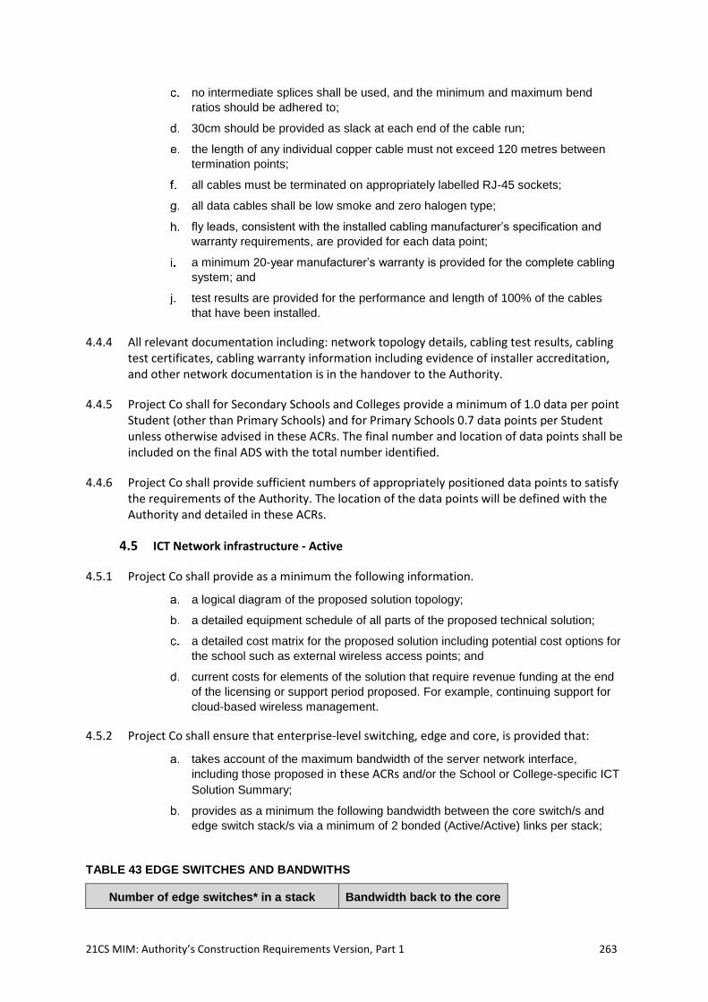
21CS MIM: Authority’s Construction Requirements Version, Part 1 263
no intermediate splices shall be used, and the minimum and maximum bend
ratios should be adhered to;
30cm should be provided as slack at each end of the cable run;
the length of any individual copper cable must not exceed 120 metres between
termination points;
all cables must be terminated on appropriately labelled RJ-45 sockets;
all data cables shall be low smoke and zero halogen type;
fly leads, consistent with the installed cabling manufacturer’s specification and
warranty requirements, are provided for each data point;
a minimum 20-year manufacturer’s warranty is provided for the complete cabling
system; and
test results are provided for the performance and length of 100% of the cables
that have been installed.
4.4.4 All relevant documentation including: network topology details, cabling test results, cabling test certificates, cabling warranty information including evidence of installer accreditation, and other network documentation is in the handover to the Authority.
4.4.5 Project Co shall for Secondary Schools and Colleges provide a minimum of 1.0 data per point Student (other than Primary Schools) and for Primary Schools 0.7 data points per Student unless otherwise advised in these ACRs. The final number and location of data points shall be included on the final ADS with the total number identified.
4.4.6 Project Co shall provide sufficient numbers of appropriately positioned data points to satisfy the requirements of the Authority. The location of the data points will be defined with the Authority and detailed in these ACRs.
4.5 ICT Network infrastructure - Active
4.5.1 Project Co shall provide as a minimum the following information.
a logical diagram of the proposed solution topology;
a detailed equipment schedule of all parts of the proposed technical solution;
a detailed cost matrix for the proposed solution including potential cost options for
the school such as external wireless access points; and
current costs for elements of the solution that require revenue funding at the end
of the licensing or support period proposed. For example, continuing support for
cloud-based wireless management.
4.5.2 Project Co shall ensure that enterprise-level switching, edge and core, is provided that:
takes account of the maximum bandwidth of the server network interface,
including those proposed in these ACRs and/or the School or College-specific ICT
Solution Summary;
provides as a minimum the following bandwidth between the core switch/s and
edge switch stack/s via a minimum of 2 bonded (Active/Active) links per stack;
TABLE 43 EDGE SWITCHES AND BANDWITHS
Number of edge switches* in a stack Bandwidth back to the core
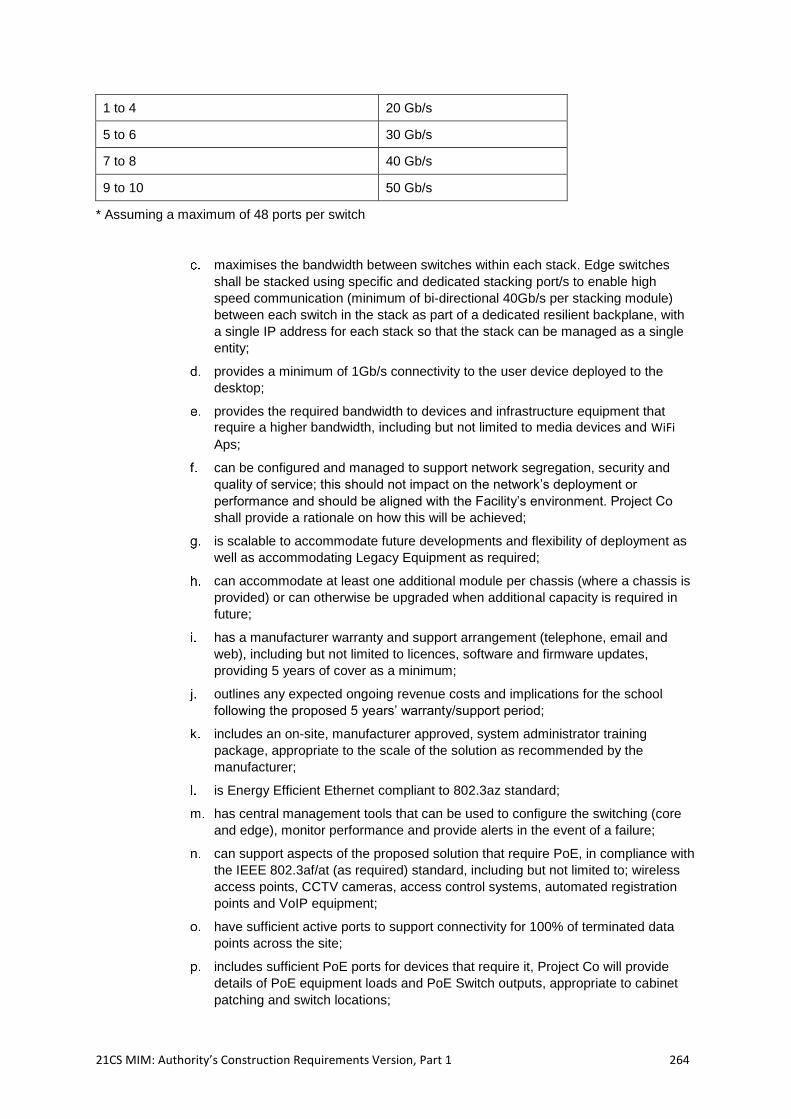
21CS MIM: Authority’s Construction Requirements Version, Part 1 264
1 to 4 20 Gb/s
5 to 6 30 Gb/s
7 to 8 40 Gb/s
9 to 10 50 Gb/s
* Assuming a maximum of 48 ports per switch
maximises the bandwidth between switches within each stack. Edge switches
shall be stacked using specific and dedicated stacking port/s to enable high
speed communication (minimum of bi-directional 40Gb/s per stacking module)
between each switch in the stack as part of a dedicated resilient backplane, with
a single IP address for each stack so that the stack can be managed as a single
entity;
provides a minimum of 1Gb/s connectivity to the user device deployed to the
desktop;
provides the required bandwidth to devices and infrastructure equipment that
require a higher bandwidth, including but not limited to media devices and WiFi
Aps;
can be configured and managed to support network segregation, security and
quality of service; this should not impact on the network’s deployment or
performance and should be aligned with the Facility’s environment. Project Co
shall provide a rationale on how this will be achieved;
is scalable to accommodate future developments and flexibility of deployment as
well as accommodating Legacy Equipment as required;
can accommodate at least one additional module per chassis (where a chassis is
provided) or can otherwise be upgraded when additional capacity is required in
future;
has a manufacturer warranty and support arrangement (telephone, email and
web), including but not limited to licences, software and firmware updates,
providing 5 years of cover as a minimum;
outlines any expected ongoing revenue costs and implications for the school
following the proposed 5 years’ warranty/support period;
includes an on-site, manufacturer approved, system administrator training
package, appropriate to the scale of the solution as recommended by the
manufacturer;
is Energy Efficient Ethernet compliant to 802.3az standard;
has central management tools that can be used to configure the switching (core
and edge), monitor performance and provide alerts in the event of a failure;
can support aspects of the proposed solution that require PoE, in compliance with
the IEEE 802.3af/at (as required) standard, including but not limited to; wireless
access points, CCTV cameras, access control systems, automated registration
points and VoIP equipment;
have sufficient active ports to support connectivity for 100% of terminated data
points across the site;
includes sufficient PoE ports for devices that require it, Project Co will provide
details of PoE equipment loads and PoE Switch outputs, appropriate to cabinet
patching and switch locations;
21CS MIM: Authority’s Construction Requirements Version, Part 1 265
has a core switch design that is resilient against the failure of any single
component, including but not limited to redundant power supply or management
modules;
is suitable for integration into a wider technical solution or support arrangement if
necessary, for example an existing Building or estate wide solution, providing
details on the standards which will enable this to occur;
provides for each switch a configuration file that allows it to be reset to the
configuration set at Actual Completion Date, with logging of any changes made to
configuration up to and including 12 months from the Actual Completion Date;
and
provides confirmation that the proposed solution supports the following conditions
and standards as a minimum:
i. that LLDP-Med is implemented in PoE+ switches;
ii. that all switches have a minimum of 512mb of CPU memory;
iii. that the switch topology supports a minimum of 16000 MAC addresses;
iv. that the network supports MST standard for spanning tree;
v. uses non-blocking switch fabric;
vi. that all switches, access points, controllers, etc. are sourced from a UK distributor, and
have a valid UK warranty; and
vii. that the UK distributor of the switch infrastructure has been consulted on the design of
the Active Infrastructure.
4.5.3 Project Co may re-use Legacy switches if available and able to meet these requirements.
4.5.4 Project Co shall provide an enterprise level wireless solution which will support a high number, and high density, of educational users by:
maximising the bandwidth between the Access Point (AP) and the switch; Project
Co shall provide a rationale for the number of ethernet ports on the AP, the total
available bandwidth between the AP and switch, and how this supports the
wireless throughput of the AP;
maximising the bandwidth between the AP and the user device by providing high
performance access points to support simultaneous use, without degradation in
performance; Project Co shall provide a rationale for the number of aerials,
spatial streams and specific technology used in the AP, and how this supports the
wireless standards associated with new and Legacy devices;
providing blanket coverage throughout the Facility which ensures
connectivity/performance is not lost whilst users roam around the Building;
providing active signal management and load balancing of user/device
connectivity, and provide rationale for how this is achieved;
providing dual band connectivity;
uses the fastest ratified standard at the time of installation and be backwards
compatible with previous standards;
configuring to support network segregation, security and Quality of Service (QoS);
Project Co should demonstrate how the initial configuration meets the Authority’s
specific requirements;
having central management tools that can be used to configure the wireless
access points, monitor performance and provide alerts in the event of a failure;
21CS MIM: Authority’s Construction Requirements Version, Part 1 266
having a manufacturer warranty and support arrangement (telephone, email and
web), including but not limited to licences, software enhancements and firmware
updates, providing 5 years of cover as a minimum;
outlining any expected ongoing revenue costs and operational implications
following the proposed 5 years’ warranty/support period;
including an on-site, manufacturer approved, system administrator training
package, appropriate to the scale of the solution as recommended by the
manufacturer;
including an on-site, manufacturer approved system administrator training
package, appropriate to the scale of the solution as recommended by the
manufacturer;
provides guest access and automated authentication for authorised users;
actively manages and load balances user connectivity;
the system is easily scalable at the central controller and can accommodate
future higher bandwidth requirements and/or the implementation of a resilient
dual controller system; including reference to licensing, hardware/software
capacity, and failover process;
minimises the impact of interference from Building Services Infrastructure and
systems and adjacent networks, and provide details of how this will be
accomplished;
is suitable for integration into a wider technical solution or support arrangement if
necessary, for example an Existing Facility or an estate wide solution providing
details on the standards which will enable this to occur;
supporting the Authority should they wish to enable external WiFi connectivity as
part of the Works; the Authority may include details in the relevant Site Specific
Brief and procure external access points (and licences) in line with the Project
Co’s Proposals, which will be treated as New Existing Equipment and installed by
the Project Co, limited to the funded Works;
each wireless controller is provided with a configuration file that allows it to be
reset to the configuration set at the Actual Completion Date, with logging of any
changes made to configurationthereafter;
Project Co will include these within the WiFi planning documentation and will
install (physically and technically) APs as per the wider wireless solution;
Project Co shall work with the Authority to ensure hardware is procured by the
Authority at the same time as Project Co to minimise risks;
where external wireless APs are included, it is the Project Co’s responsibility to
ensure that appropriate grounding and surge protection is provided;
Project Co may consider re-use of a Legacy wireless solution if available; and
Project Co shall provide any network infrastructure - wired and wireless, elements
and any other equipment required to deliver the Services (in accordance with the
Service Level Specification).
4.6 ICT Infrastructure Tests
4.6.1 Project Co shall undertake P1 Infrastructure Tests in accordance with the requirements detailed in Annex 2 to these ACRs. These tests will ensure that the structured cabling and wireless local area network is installed correctly and completely prior to handing over to the ICT Installer. Once all active equipment and final end user devices are installed and operating at normally occupied capacity, it is the responsibility of the Project Co to undertake further
21CS MIM: Authority’s Construction Requirements Version, Part 1 267
WLAN/WiFi tests to ensure required coverage is achieved as detailed in the P2 Infrastructure Test in accordance with the requirements detailed in Annex 2 to these ACRs
4.7 Local Technology – Core
4.7.1 Project Co shall provide any additional equipment in relation to Local Technology core elements that he requires in order to deliver the Services.
4.7.2 Where required Project Co will decant all Local Technology systems as set out in paragraph 4.11 (ICT Decant Protocol) of Part 1 (Generic Design Requirements) of these ACRs and Table 45, ‘The ICT Responsibilities Matrix’ of Part 1 (Generic Design Requirements) of these ACRs.
4.8 Local Technology – AV
4.8.1 In relation to fixings, brackets, cables & power (containment, routing, termination and presentation) Project Co shall provide all necessary fittings, poles, frames, rigs, cages and brackets required for the installation, mounting, commissioning and other general installation Works for Legacy ICT Equipment.
4.8.2 In relation to the hardware only Project Co shall be responsible for decommissioning, decanting, reinstalling (mounting and connection to installed cabling) and testing of the following items:
Data projectors;
Interactive whiteboards;
Sound systems to support learning in teaching spaces, such as speaker systems
connected to interactive displays and other ICT and audio-visual equipment;
Display screens;
IP TV broadcast system (Note that the provision of aerials, dishes etc. is covered
in paragraph 4.6);
stage lighting control; and
other systems as included in these ACRs.
4.8.3 Otherwise Project Co will decant all AV equipment as set out paragraph 4.11 (ICT Decant Protocol) of Part 1 (Generic Design Requirements) of these ACRs, Table 45, ‘The ICT Responsibilities Matrix’ and the SSB.
4.8.4 Any ceiling mounted Teaching Area display technologies including pole mounted and short throw projection should be fixed directly or indirectly to the soffits.
4.8.5 Project Co shall ensure that the design considers the nature of the specific display technology to be used and provides ways of allowing the display to be viewed clearly and without reflections whilst retaining a space which benefits from daylight.
4.8.6 Project Co shall provide an AV wiring loom into every teaching space, hall and meeting room (as required). The loom should support the current AV requirements of the Facility including but not limited to VGA, USB and dual HDMI and be presented via a faceplate.
4.8.7 In specialist areas, for example science, food rooms and design & technology rooms, the faceplate location shall take into account the teacher desk and demonstration position to
21CS MIM: Authority’s Construction Requirements Version, Part 1 268
ensure that appropriate connectivity can be maintained between the teacher PC/device and the teaching area AV equipment – and that sight lines and viewing angles for Students are maintained.
4.8.8 Where partitions support display equipment, including but not limited to interactive whiteboards, interactive projectors and interactive LED screens, suitable patressing shall be installed as required.
4.8.9 Where partitions support other display solutions, such as digital signage screens, or cashless revaluation units, parsing shall be installed across a suitable area, at a suitable height for the respective equipment, and be coordinated with appropriate power and data sockets, which may need to be concealed within or behind the respective unit.
4.8.10 Project Co shall install and test AV equipment as Table 45, ‘The ICT Responsibilities Matrix’of Part 1 (Generic Design Requirements) of these ACRs.
4.8.11 Where a ‘Teacher Wall’ is required, it should have agreed power and data to accommodate interactive displays and/or associated projector; the interactive display area must be free from obstructions, not limited to dado, to enable flexible height installation of the display for staff and Student use.
4.8.12 Specialist suppliers shall be consulted on the most appropriate type of any new audio-visual equipment, taking account of any Initial ICT Equipment such as control equipment or scaffolding.
4.8.13 Where the legacy AV equipment from drama, dance, halls and music spaces is suitable, Project Co will Decant and reinstall, providing all necessary fixtures, fittings, cabling and infrastructure.
4.8.14 Where the legacy AV equipment from drama, dance, halls and music spaces and other areas is not suitable for decant, the Authority may procure equivalent new equipment which Project Co will decant and reinstall, providing all necessary fixtures, fittings, cabling and infrastructure.
4.9 Automated Systems
4.9.1 Project Co shall decommission, decant, reinstall, (mounting and connection to installed cabling) and test any cashless catering system (hardware only)
4.9.2 Where a specific Dining and Social area is required in the SoA, Project Co shall ensure that it is designed so that there is adequate space for till points, revaluation units, digital signage and serving areas to service the number of diners in any sitting, as given in these ACRs. A review of the small power and data requirements for this equipment should be conducted and these connections supplied.
4.9.3 Project Co shall specify, supply, install and commission the access control system;
4.9.4 Project Co shall decommission, Decant, reinstall, (mounting and connection to installed cabling) and test any Student automatic registration systems including visitor registration schemes at main reception;
4.9.5 Project Co shall decommission, Decant, reinstall, (mounting and connection to installed cabling) and test any internal CCTV;
21CS MIM: Authority’s Construction Requirements Version, Part 1 269
4.9.6 where an existing or new legacy internal IP-based system is decanted/installed, Project Co may wish to integrate external CCTV cameras if provided, with the internal system;
4.9.7 Project Co shall ensure that all fixings, brackets, power & cables (containment, routing, termination and presentation) are provided for the installation and commissioning of all Works requiring alteration of the Building's structure in order to facilitate the installation of the items listed in this section of the matrix; and
4.9.8 Project Co shall provide any further automated systems, elements that are required to deliver the Services.
4.10 Telephony, Internet and TV signal
4.10.1 The Authority will require any or all of the following:
analogue lift phone line;
ISDN30/ISDN2 with direct lines identified and telephone extension;
BT Redcare;
franking machine and fax services;
spare phone line in the event of a telephone system failure;
the Building Management Systems (BMS); and
kitchen line,
as specified in the relevant Site Specific Brief
4.10.2 Project Co shall provide all necessary cabling and connections (excess construction and last mile), routing and ducting.
4.10.3 Project Co shall fund and coordinate the ordering and installation of the broadband connection (last mile, on-site equipment and an active connection to the internet etc.) and digital and analogue telephone lines. This will include, but not be limited to, ISDN, Redcare, Alarm, Lift or SIP trunking Service Infrastructure and the relocation of existing connections or provision of new. An independent broadband connection will be provided for sole use of the BMS/EMS, and the Automated Energy Data Collection Portal. Project Co will maintain, where required, existing communication connections from the existing Buildings to other locations both inside and outside the red line and provide new connections where necessary.
4.10.4 The orders will be placed by the Authority and/or the School Entity, in the case of a school’s project, or another Authority Party.
4.10.5 Works will be carried out in a way that minimises disruption to the Facility, including but not limited to maintaining connectivity during exam result delivery.
4.10.6 In the event that Project Co installs a private ‘Telco Green Cabinet’ (Customer premise equipment), on the Site to facilitate and de-risk broadband Works Project Co will provide the following as a minimum:
1 x BT OpenReach duct;
2 x Private ducts;
1 x power outlets on a dedicated circuit; and
1 x 12 core 10gb/s fibre cable, with cable specification appropriate to the cable
distance, terminated within the Private CPE and Facility server room.
21CS MIM: Authority’s Construction Requirements Version, Part 1 270
4.10.7 Where a private customer premise equipment (CPE) is provided, Project Co remains responsible for the termination of the broadband service within the server room, and for connectivity to the service providers main (public) roadside Telco Green Cabinet.
4.10.8 Project Co shall provide an enterprise level telephone system (core and handsets), with sufficient fixed handsets for offices and admin areas with the following functionality:
a central switchboard;
fixed handsets, making use of the structured cabling and IP network, for all senior
leadership team offices and admin staff;
headsets for hands-free operation for reception staff;
voicemail forwarding as e-mail attachment for all staff; and
Auto-Attendant (or automated attendant) voice menu system allowing callers to
be transferred to an extension without going through a telephone operator or
receptionist.
4.10.9 Project Co shall provide a solution to enable the Facility to make and receive calls in the case of a power failure.
4.10.10 The telephone system will have a manufacturer warranty and support arrangement, including firmware and software upgrades (telephone, email and web), providing 5 years of cover as a minimum.
4.10.11 Project Co shall provide training for the Telephony system.
4.10.12 In relation to aerials, dish, LNB, actuators, down-leads, distribution amplifier Project Co shall provide a digital terrestrial receiver, capable of supporting simultaneous access to multiple channels with the feed terminating in the server room.
4.10.13 In relation to telephony, internet and TV, elements Project Co shall supply any additional equipment that is required to deliver the Services.
4.11 ICT Decant Protocol
4.11.1 Where decant is required, Project Co shall provide all resources to decommission, package, store, move and re-commission Initial ICT Equipment and other ICT Equipment in accordance with this paragraph 4.11 and the Decant Protocol set out in Section 2 (Decant Protocol) of Schedule 11 (Equipment) of this Agreement.
4.11.2 A decant list will be agreed between the Authority and Project Co. Project Co and Authority will specify the date on which the list is frozen.
4.11.3 Where the Authority (and/or the relevant School Entity/(ies), in the case of a School(s) project) is procuring New Replacement ICT Equipment for Decant by Project Co to a Facility (see paragraph 4.11.12 below), Project Co shall co-ordinate with the Authority (and where relevant the School Entity/(ies), in the case of a Schools project), for the delivery, storage and insurance for installation before the ICT Handover Date.
4.11.4 Project Co shall provide all resources to decommission and decant the Initial ICT Equipment and services. This includes:
testing;
de-installation
21CS MIM: Authority’s Construction Requirements Version, Part 1 271
packaging;
transport;
storage;
un-packing;
installation (as ‘The ICT Responsibilities Matrix’); and
testing, (as the Implementation and User Acceptance Testing Schedule).
4.11.5 Project Co shall co-ordinate and project-manage the resources required to ensure that the Authority (and each School Entity, in the case of a School(s) project), can operate with their Legcy ICT Equipment within the Building.
4.11.6 Project Co shall ensure ICT Assets are decanted to the correct locations specified by the School Entity or the Authority, in accordance with the Construction Phase Access Protocol the Authority's Construction Requirements and the Decant Protocol.
4.11.7 Where the Authority has a technical support team or a service provider, Project Co shall liaise with them through the Authority to ensure a smooth transition to the Facility's ICT solution, including the technical decant process.
4.11.8 Project Co is responsible for the Initial ICT Equipment from Decant of the ICT Assets (the point of de-installation in the case of Legacy ICT Equipment) and is not responsible during Authority Control Periods (as set out in paragraph 4 (Control of ICT Assets) of Section 2 (Construction Phase Access Protocol) of Schedule 34 (Joint Operating Protocol).
4.11.9 In the event of damage to, loss or failure of the ICT Equipment during the period which Project Co is responsible for it, Project Co shall return the equipment to its previous condition or replace with suitable new, at no cost to the Authority (or any School Entity in the case of a School(s) project) in accordance with paragraph 14 (Damange and Loss During the Move) of Section 2 (Decant Protocol) of Schedule 11 (Equipment).
4.11.10 Project Co will ensure relevant conditions for maintaining existing warranties for Initial ICT Equipment are adhered to throughout the decant process, for example where a certified installer is required for decommissioning and re-installing a piece of equipment such as Teaching Area AV equipment or leased devices.
4.11.11 In the event that Decant by Project Co is not required in respect of any ICT Equipment and the Authority is making alternative arrangements for delivery of such ICT Equipment to a Faclity,, Project Co will provide the necessary access, secure storage and insurances so that the installation and testing of ICT equipment is not delayed beyond Facility opening.
4.11.12 New ICT Equipment
The Authority may procure new Initial ICT Equipment to replace any unsuitable Legacy ICT Equipment, of an equivalent type or specification to the Legacy ICT Equipment, for delivery to the Facility.
The list of Legacy ICT Equipment shall be captured in the ICT Solution Protocol, the ADS and the Loaded Room Layout Drawings. This includes, but is not limited to:
Classroom A/V equipment;
digital signage;
internal CCTV cameras;
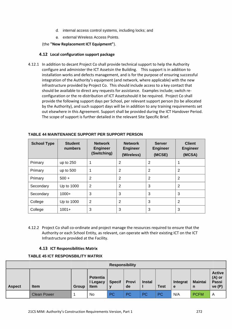
21CS MIM: Authority’s Construction Requirements Version, Part 1 272
internal access control systems, including locks; and
external Wireless Access Points.
(the "New Replacement ICT Equipment").
4.12 Local configuration support package
4.12.1 In addition to decant Project Co shall provide technical support to help the Authority configure and administer the ICT Assetsin the Building. This support is in addition to installation works and defects management, and is for the purpose of ensuring successful integration of the Authority’s equipment (and network, where applicable) with the new infrastructure provided by Project Co. This should include access to a key contact that should be available to direct any requests for assistance. Examples include; switch re-configuration or the re-distribution of ICT Assetsshould it be required. Project Co shall provide the following support days per School, per relevant support person (to be allocated by the Authority), and such support days will be in addition to any training requirements set out elsewhere in this Agreement. Support shall be provided during the ICT Handover Period. The scope of support is further detailed in the relevant Site Specific Brief.
TABLE 44 MAINTENANCE SUPPORT PER SUPPORT PERSON
School Type Student
numbers
Network
Engineer
(Switching)
Network
Engineer
(Wireless)
Server
Engineer
(MCSE)
Client
Engineer
(MCSA)
Primary up to 250 1 2 2 1
Primary up to 500 1 2 2 2
Primary 500 + 2 2 2 2
Secondary Up to 1000 2 2 3 2
Secondary 1000+ 3 3 3 3
College Up to 1000 2 2 3 2
College 1001+ 3 3 3 3
4.12.2 Project Co shall co-ordinate and project manage the resources required to ensure that the Authority or each School Entity, as relevant, can operate with their existing ICT on the ICT Infrastructure provided at the Facility.
4.13 ICT Responsibilities Matrix
TABLE 45 ICT RESPONSBILITY MATRIX
Responsibility
Aspect Item Group
Potential Legacy Item
Specify
Provide
Install Test
Integrate
Maintain
Active (A) or Passive (P)
Clean Power 1 No PC PC PC PC N/A PCFM A
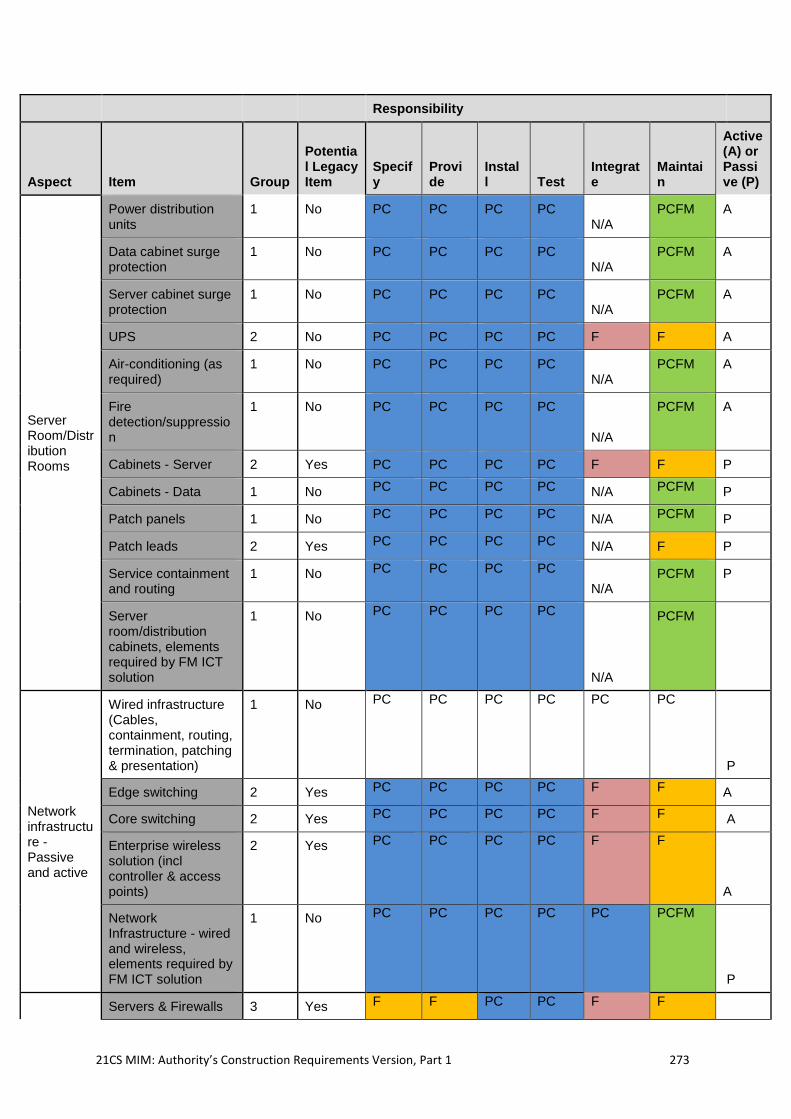
21CS MIM: Authority’s Construction Requirements Version, Part 1 273
Responsibility
Aspect Item Group
Potential Legacy Item
Specify
Provide
Install Test
Integrate
Maintain
Active (A) or Passive (P)
Server Room/Distribution Rooms
Power distribution units
1 No PC PC PC PC N/A
PCFM A
Data cabinet surge protection
1 No PC PC PC PC N/A
PCFM A
Server cabinet surge protection
1 No PC PC PC PC N/A
PCFM A
UPS 2 No PC PC PC PC F F A
Air-conditioning (as required)
1 No PC PC PC PC N/A
PCFM A
Fire detection/suppression
1 No PC PC PC PC
N/A
PCFM A
Cabinets - Server 2 Yes PC PC PC PC F F P
Cabinets - Data 1 No PC PC PC PC N/A PCFM P
Patch panels 1 No PC PC PC PC N/A PCFM P
Patch leads 2 Yes PC PC PC PC N/A F P
Service containment and routing
1 No PC PC PC PC
N/A PCFM P
Server room/distribution cabinets, elements required by FM ICT solution
1 No PC PC PC PC
N/A
PCFM
Network infrastructure - Passive and active
Wired infrastructure (Cables, containment, routing, termination, patching & presentation)
1 No PC PC PC PC PC PC
P
Edge switching 2 Yes PC PC PC PC F F A
Core switching 2 Yes PC PC PC PC F F A
Enterprise wireless solution (incl controller & access points)
2 Yes PC PC PC PC F F
A
Network Infrastructure - wired and wireless, elements required by FM ICT solution
1 No PC PC PC PC PC PCFM
P
Servers & Firewalls 3 Yes F F PC PC F F
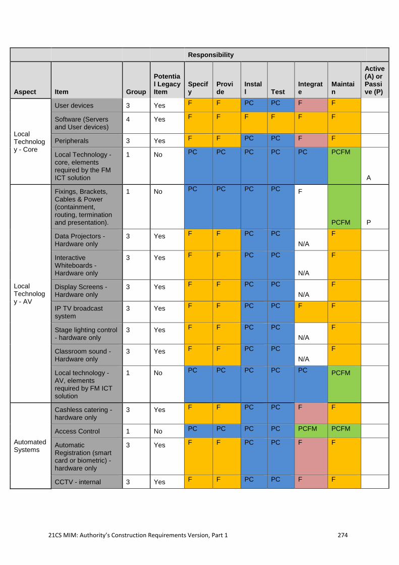
21CS MIM: Authority’s Construction Requirements Version, Part 1 274
Responsibility
Aspect Item Group
Potential Legacy Item
Specify
Provide
Install Test
Integrate
Maintain
Active (A) or Passive (P)
Local Technology - Core
User devices 3 Yes F F PC PC F F
Software (Servers and User devices)
4 Yes F F F F F F
Peripherals 3 Yes F F PC PC F F
Local Technology - core, elements required by the FM ICT solution
1 No PC PC PC PC PC PCFM
A
Local Technology - AV
Fixings, Brackets, Cables & Power (containment, routing, termination and presentation).
1 No PC PC PC PC F
PCFM P
Data Projectors - Hardware only
3 Yes F F PC PC
N/A
F
Interactive Whiteboards - Hardware only
3 Yes F F PC PC
N/A
F
Display Screens - Hardware only
3 Yes F F PC PC
N/A
F
IP TV broadcast system
3 Yes F F PC PC F F
Stage lighting control - hardware only
3 Yes F F PC PC
N/A
F
Classroom sound - Hardware only
3 Yes F F PC PC
N/A
F
Local technology - AV, elements required by FM ICT solution
1 No PC PC PC PC PC PCFM
Automated Systems
Cashless catering - hardware only
3 Yes F F PC PC F F
Access Control 1 No PC PC PC PC PCFM PCFM
Automatic Registration (smart card or biometric) - hardware only
3 Yes F F PC PC F F
CCTV - internal 3 Yes F F PC PC F F
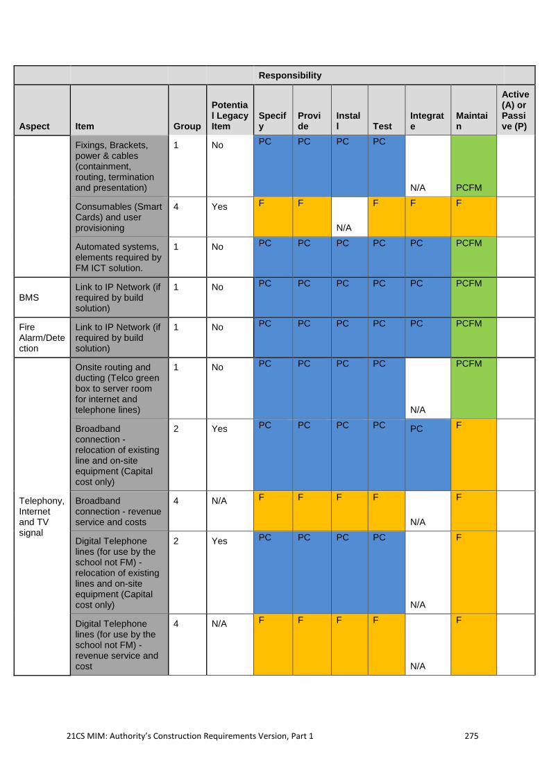
21CS MIM: Authority’s Construction Requirements Version, Part 1 275
Responsibility
Aspect Item Group
Potential Legacy Item
Specify
Provide
Install Test
Integrate
Maintain
Active (A) or Passive (P)
Fixings, Brackets, power & cables (containment, routing, termination and presentation)
1 No PC PC PC PC
N/A PCFM
Consumables (Smart Cards) and user provisioning
4 Yes F F
N/A
F F F
Automated systems, elements required by FM ICT solution.
1 No PC PC PC PC PC PCFM
BMS Link to IP Network (if required by build solution)
1 No PC PC PC PC PC PCFM
Fire Alarm/Detection
Link to IP Network (if required by build solution)
1 No PC PC PC PC PC PCFM
Telephony, Internet and TV signal
Onsite routing and ducting (Telco green box to server room for internet and telephone lines)
1 No PC PC PC PC
N/A
PCFM
Broadband connection - relocation of existing line and on-site equipment (Capital cost only)
2 Yes PC PC PC PC PC F
Broadband connection - revenue service and costs
4 N/A F F F F
N/A
F
Digital Telephone lines (for use by the school not FM) - relocation of existing lines and on-site equipment (Capital cost only)
2 Yes PC PC PC PC
N/A
F
Digital Telephone lines (for use by the school not FM) -revenue service and cost
4 N/A F F F F
N/A
F
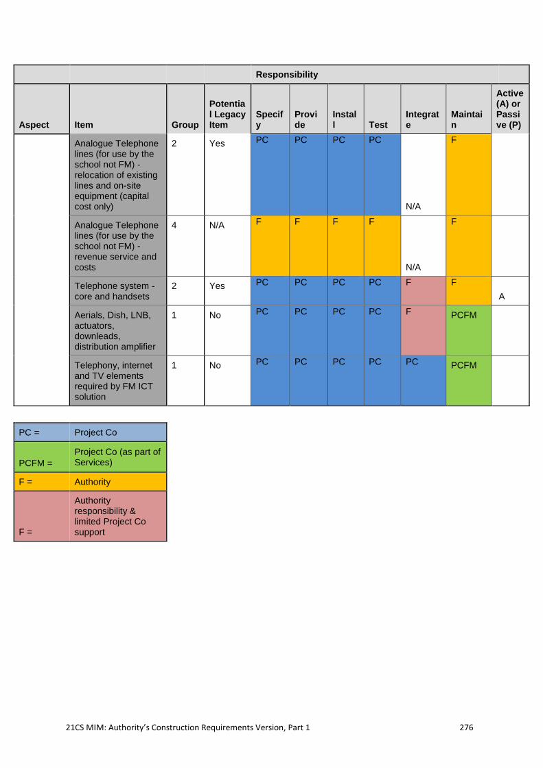
21CS MIM: Authority’s Construction Requirements Version, Part 1 276
Responsibility
Aspect Item Group
Potential Legacy Item
Specify
Provide
Install Test
Integrate
Maintain
Active (A) or Passive (P)
Analogue Telephone lines (for use by the school not FM) - relocation of existing lines and on-site equipment (capital cost only)
2 Yes PC PC PC PC
N/A
F
Analogue Telephone lines (for use by the school not FM) - revenue service and costs
4 N/A F F F F
N/A
F
Telephone system - core and handsets
2 Yes PC PC PC PC F F
A
Aerials, Dish, LNB, actuators, downleads, distribution amplifier
1 No PC PC PC PC F PCFM
Telephony, internet and TV elements required by FM ICT solution
1 No PC PC PC PC PC PCFM
PC = Project Co
PCFM =
Project Co (as part of Services)
F = Authority
F =
Authority responsibility & limited Project Co support
21CS MIM: Authority’s Construction Requirements Version, Part 1 277
5. Annex 1 Statutory Requirements and Guidance
5.1 Introduction
5.1.1 Project Co is required to ensure that the designs for all Facilities comply with all current relevant regulations, including those listed here in Annex I. Project Co should be aware of all current relevant guidance on School and College premises, including that listed here.
5.2 Statutory Requirements
Legislation applying to School premises only
5.2.1 The Education (School Premises) Regulations 1999 (SPRs) - these apply to all existing and new schools maintained by a Local Authority. They cover toilet and washing facilities, medical accommodation, health, safety and welfare, acoustics, lighting, water supplies and outdoor space.
5.2.2 The National Minimum Standards for Boarding Schools (2015) cover requirements for boarding accommodation at all mainstream boarding schools, for all age groups of pupils up to 18. There is a separate set of national minimum standards for residential special schools.
5.2.3 Legislation applying to different types of buildings, including schools
5.2.4 There is a substantial amount of other Law that applies to all buildings, including schools. Regard should be had to the provisions of this Law including, but not limited to:
the Health and Safety at Work etc Act 1974 (HSWA);
the Workplace (Health, Safety and Welfare) Regulations 1992, together with its
Approved Code of Practice and Guidance (collectively – WRs);
the Equality Act 2010 (EQA);
the Regulatory Reform (Fire Safety) Order 2005 (RRFO); and
The Control of Substances Hazardous to Health Regulations 2002 (as amended)
(COSHH).
5.2.5 As with other building types, developments at schools are bound by normal planning controls, details of which can be found on the government Planning Portal. The Department for Communities and Local Government (DCLG, or Communities) published the National
Planning Policy Framework on 27 March 2012, which aims to make the planning system less complex and more accessible, in part by significantly reducing the number of regulations in place. It also aims to promote sustainable development.
5.2.6 Planning Policy Wales issues Technical Advice Notes and procedural guidance is further issued in circulars from Welsh Government/ National Assembly for Wales and Welsh Office.
5.2.7 Where a Site contains an Existing Facility, Project Co (or WEP Co during a New Project Develoipment Stage 1 or Stage 2) shall apply for a Certificate of Immunity from Listing to Cadw, unless the Authority specifically agrees that such an application is not required. Project Co (or WEP Co) shall have notified the planning authority at the time of the application.
5.2.8 Construction work at schools is subject to approval under the Approved Documents for Wales which took effect from 2017.
21CS MIM: Authority’s Construction Requirements Version, Part 1 278
5.2.9 Regard should also be had to The Construction (Design and Management) Regulations 2015, which concerns ensuring the safety of the workforce, occupants and the public while construction Works are carried out.
5.2.10 The Building Regulations set minimum standards for the design and construction of buildings and exist mainly to ensure the health and safety of people in and around buildings, but also cover energy conservation and accessibility. The fourteen technical “Parts” of the Building Regulations are supported by Approved Documents, which show how the requirements of the regulations can be complied with.
5.2.11 Developments on School and College sites are also bound by environmental Law, such as the:
Environmental Protection Act 1990; and
Site Waste Management Regulations 2008.
5.3 Regulatory Guidance
5.3.1 Building Bulletin (BB) 101, Ventilation of school buildings, downloadable only, 2017
5.3.2 This guidance advises on how to meet the requirements of Part F of the Building Regulations as they apply to Schools and is cited in AD F.
5.3.3 BB 100, Design for Fire Safety in Schools, NBS/RIBA 2007
5.3.4 This guidance advises on how to meet the requirements of Part B of the Building Regulations as they apply to Schools and is cited in AD B. It is being reviewed and revised guidance on fire safety in schools is expected.
5.3.5 The above list is not an exhaustive list of Statutory Requirements; Project Co should satisfy themselves that they have adhered to all relevant Statutory guidance.
5.4 Design Guidance
5.4.1 Listed below is the current design guidance for Schools, together with technical guidance, best practice and case studies.
BB 104, Area Guidelines for SEN (D) and Alternative Provision, 2015
BB 103, Area Guidelines for Mainstream Schools, 2015
BB 99, Briefing Framework for Primary School Projects, TSO 2006
BB 98, Briefing Framework for Secondary School Projects, TSO 2004)
BB 88, Fume Cupboards in Schools, TSO 2014
Design of sustainable schools: case studies, TSO 2006
Music Accommodation in Secondary Schools: a design guide, NBS/RIBA 2010
5.5 Welsh Government Policy and Guidance
School toilets: Good practice guidance for schools in Wales, 2012
Guides to making your 21st Century Schools and educational facilities
sustainable, 2018
Guidance for Community Benefits, 2018
21CS MIM: Authority’s Construction Requirements Version, Part 1 279
Welsh Government Sustainable Building Standards, 2017
Ventilation Guidance
Building Bulletin 101 – ‘Guidelines on ventilation, thermal comfort and indoor air
quality in schools’ (BB101)
DW/172 – ‘Specification for Kitchen Ventilation Systems’
DW/144 – ‘Specification for Sheet Metal Ductwork’
HSE Catering Information Sheet No 10 – ‘Ventilation in catering Kitchens’
HSE Catering Information Sheet No 23 – ‘Gas safety in catering and hospitality’
IGEM/UP/11 – ‘Gas installations for educational establishments’
CIBSE TM 42 – ‘Fan Application Guide’
BS EN 16282-2 – ‘Equipment for commercial Kitchens - Components for
ventilation of commercial kitchens - Part 2: Kitchen ventilation hoods; design and
safety requirements’
BS EN 16282-3 – ‘Equipment for commercial kitchens - Components for
ventilation in commercial kitchens - Part 3: Kitchen ventilation ceilings; Design
and safety requirements’
HSE Catering Information Sheet 23 – ‘Gas safety in catering and hospitality
IGEM/UP/11 – ‘Gas installations for educational establishments’
CLEAPSS Guide G9 – ‘Fume Cupboards in Schools’
BS EN 14175 – ‘Fume cupboards. Type test methods’
BS EN 14175-2 – ‘Fume cupboards. Safety and performance requirements’
BS EN 14175-3 – ‘Fume cupboards. Recommendations for the exchange of
information and recommendations for installation’
BS EN 14175-5 – ‘Fume cupboards. Recommendations for installation and
maintenance’
2015 ASHRAE Handbook - HVAC Applications, Chapter 45, Building Air Intake
and Exhaust Design
HSG 258 – ‘Controlling airborne contaminants at work: A guide to Local Exhaust
Ventilation (LEV)’
Gas Safety (Installation and Use) Regulations 1998, Regulation 2 (6) (b)
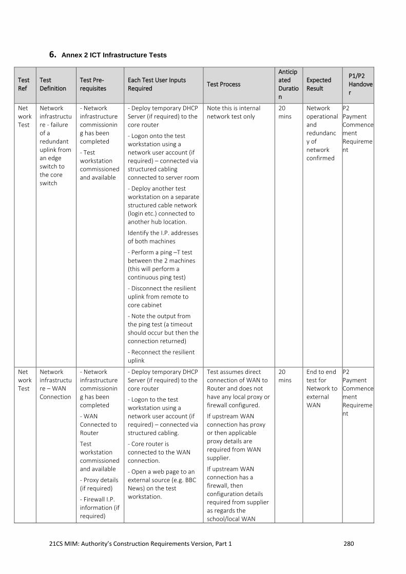
21CS MIM: Authority’s Construction Requirements Version, Part 1 280
6. Annex 2 ICT Infrastructure Tests
Test Ref
Test Definition
Test Pre-requisites
Each Test User Inputs Required
Test Process
Anticipated Duration
Expected Result
P1/P2 Handover
Network Test
Network infrastructure - failure of a redundant uplink from an edge switch to the core switch
- Network infrastructure commissioning has been completed
- Test workstation commissioned and available
- Deploy temporary DHCP Server (if required) to the core router
- Logon onto the test workstation using a network user account (if required) – connected via structured cabling connected to server room
- Deploy another test workstation on a separate structured cable network (login etc.) connected to another hub location.
Identify the I.P. addresses of both machines
- Perform a ping –T test between the 2 machines (this will perform a continuous ping test)
- Disconnect the resilient uplink from remote to core cabinet
- Note the output from the ping test (a timeout should occur but then the connection returned)
- Reconnect the resilient uplink
Note this is internal network test only
20 mins
Network operational and redundancy of network confirmed
P2 Payment Commencement Requirement
Network Test
Network infrastructure – WAN Connection
- Network infrastructure commissioning has been completed
- WAN Connected to Router
Test workstation commissioned and available
- Proxy details (if required)
- Firewall I.P. information (if required)
- Deploy temporary DHCP Server (if required) to the core router
- Logon to the test workstation using a network user account (if required) – connected via structured cabling.
- Core router is connected to the WAN connection.
- Open a web page to an external source (e.g. BBC News) on the test workstation.
Test assumes direct connection of WAN to Router and does not have any local proxy or firewall configured.
If upstream WAN connection has proxy or then applicable proxy details are required from WAN supplier.
If upstream WAN connection has a firewall, then configuration details required from supplier as regards the school/local WAN
20 mins
End to end test for Network to external WAN
P2 Payment Commencement Requirement
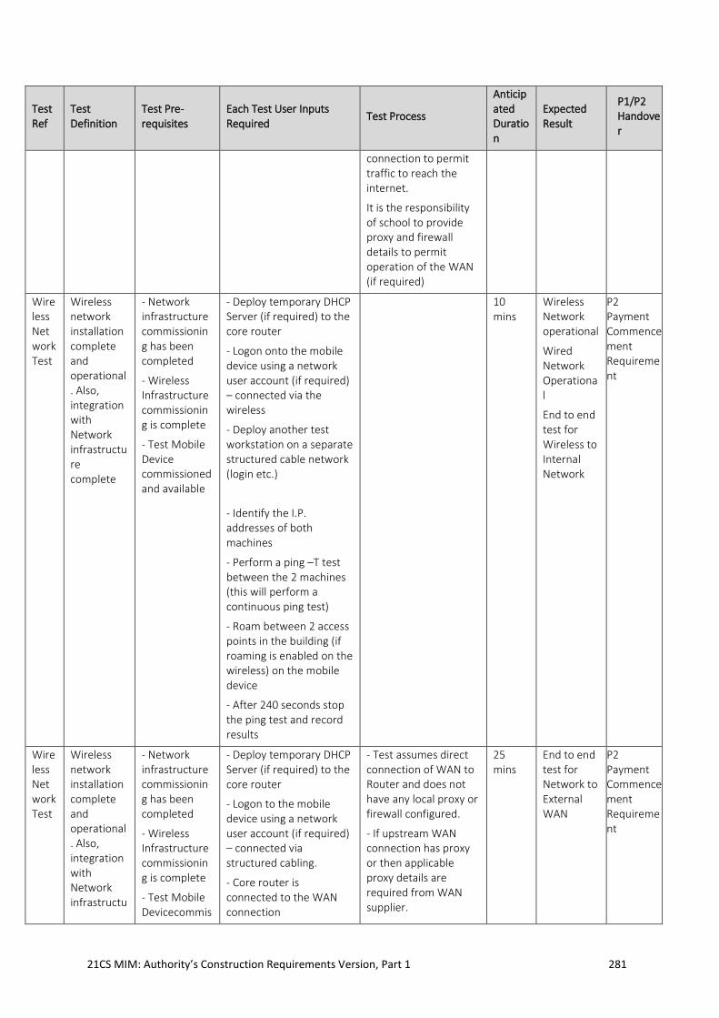
21CS MIM: Authority’s Construction Requirements Version, Part 1 281
Test Ref
Test Definition
Test Pre-requisites
Each Test User Inputs Required
Test Process
Anticipated Duration
Expected Result
P1/P2 Handover
connection to permit traffic to reach the internet.
It is the responsibility of school to provide proxy and firewall details to permit operation of the WAN (if required)
Wireless Network Test
Wireless network installation complete and operational. Also, integration with Network infrastructure complete
- Network infrastructure commissioning has been completed
- Wireless Infrastructure commissioning is complete
- Test Mobile Device commissioned and available
- Deploy temporary DHCP Server (if required) to the core router
- Logon onto the mobile device using a network user account (if required) – connected via the wireless
- Deploy another test workstation on a separate structured cable network (login etc.)
- Identify the I.P. addresses of both machines
- Perform a ping –T test between the 2 machines (this will perform a continuous ping test)
- Roam between 2 access points in the building (if roaming is enabled on the wireless) on the mobile device
- After 240 seconds stop the ping test and record results
10 mins
Wireless Network operational
Wired Network Operational
End to end test for Wireless to Internal Network
P2 Payment Commencement Requirement
Wireless Network Test
Wireless network installation complete and operational. Also, integration with Network infrastructu
- Network infrastructure commissioning has been completed
- Wireless Infrastructure commissioning is complete
- Test Mobile Devicecommis
- Deploy temporary DHCP Server (if required) to the core router
- Logon to the mobile device using a network user account (if required) – connected via structured cabling.
- Core router is connected to the WAN connection
- Test assumes direct connection of WAN to Router and does not have any local proxy or firewall configured.
- If upstream WAN connection has proxy or then applicable proxy details are required from WAN supplier.
25 mins
End to end test for Network to External WAN
P2 Payment Commencement Requirement
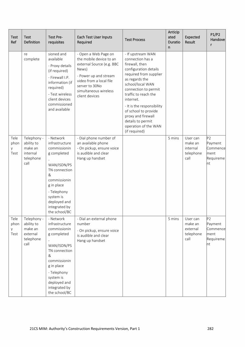
21CS MIM: Authority’s Construction Requirements Version, Part 1 282
Test Ref
Test Definition
Test Pre-requisites
Each Test User Inputs Required
Test Process
Anticipated Duration
Expected Result
P1/P2 Handover
re complete
sioned and available
- Proxy details (if required)
- Firewall I.P. information (if required)
- Test wireless client devices commissioned and available
- Open a Web Page on the mobile device to an external Source (e.g. BBC News)
- Power up and stream video from a local file server to 30No simultaneous wireless client devices
- If upstream WAN connection has a firewall, then configuration details required from supplier as regards the school/local WAN connection to permit traffic to reach the internet.
- It is the responsibility of school to provide proxy and firewall details to permit operation of the WAN (if required)
Telephony Test
Telephony - ability to make an internal telephone call
- Network infrastructure commissioning completed
- WAN/ISDN/PSTN connection & commissioning in place
- Telephony system is deployed and integrated by the school/BC
- Dial phone number of an available phone - On pickup, ensure voice is audible and clear Hang up handset
5 mins User can make an internal telephone call
P2 Payment Commencement Requirement
Telephony Test
Telephony - ability to make an external telephone call
- Network infrastructure commissioning completed
- WAN/ISDN/PSTN connection & commissioning in place
- Telephony system is deployed and integrated by the school/BC
- Dial an external phone number
- On pickup, ensure voice is audible and clear Hang up handset
5 mins User can make an external telephone call
P2 Payment Commencement Requirement
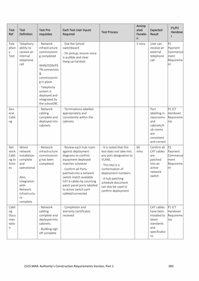
21CS MIM: Authority’s Construction Requirements Version, Part 1 283
Test Ref
Test Definition
Test Pre-requisites
Each Test User Inputs Required
Test Process
Anticipated Duration
Expected Result
P1/P2 Handover
Telephony Test
Telephony - ability to receive an internal telephone call
- Network infrastructure commissioning completed
- WAN/ISDN/PSTN connection & commissioning in place
- Telephony system is deployed and integrated by the school/BC
- Dial the School switchboard
- On pickup, ensure voice is audible and clear Hang up handset
5 mins User can receive an external telephone call
P2 Payment Commencement Requirement
General Cabling
- Network cabling complete and deployed into cabinets
- Terminations labelled appropriately and consistently within the cabinets
Port labelling in classrooms and cabinets/hub rooms are consistent and correct
P1 ICT Handover Requirements
Network Cabling to Actives
Wired network installation complete and operational.
Also, integration with Network infrastructure complete
- Network infrastructure commissioning has been completed
- Review each hub room against deployment diagrams to confirm equipment deployed matches schedule
- Confirm all Ports patched into a network switch match available CAT 6 cables by counting patch panel ports labelled to active switch port cabled/connected
- It is noted that this test does not take into any port designation to VLANS.
- This test is a conformation of deployment numbers.
- A hub patching schedule document can also be used to confirm deployment
60 mins
Confirm all CAT cables are patched into an active network switch
P2 Payment Commencement Requirement
Cabling Documentation
- Network cabling complete and deployed into cabinets.
- Building sign off complete
- Completion and warranty certificates received
CAT cables have been installed to latest standards and specifications
P1 ICT Handover Requirements
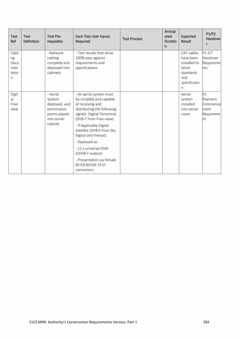
21CS MIM: Authority’s Construction Requirements Version, Part 1 284
Test Ref
Test Definition
Test Pre-requisites
Each Test User Inputs Required
Test Process
Anticipated Duration
Expected Result
P1/P2 Handover
Cabling Documentation
- Network cabling complete and deployed into cabinets
- Test results that show 100% pass against requirements and specifications
CAT cables have been installed to latest standards and specification
P1 ICT Handover Requirements
Digital Freeview
- Aerial System deployed, and termination points placed into server cabinet
- An aerial system must be installed and capable of receiving and distributing the following signals: Digital Terrestrial (DVB-T from Free-view)
- If Applicable Digital Satellite (DVB-S from Sky Digital and freesat)
- Deployed as
- 12 x universal DVB-S/DVB-T outputs
- Presentation via female BS EN 60169-24 (F-connectors
Aerial system installed into server room.
P2 Payment Commencement Requirement