ubc - diaphragm design requirements
TRANSCRIPT
Chapter 3 – General Provisions & Seismic Design Criteria SDR Workbook – 2018 IBC Version
1-36 Steven T. Hiner, MS, SE
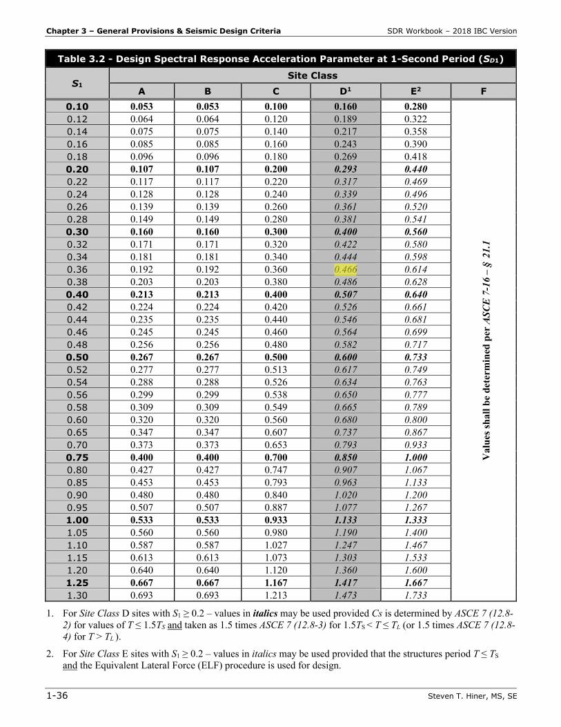
Table 3.2 - Design Spectral Response Acceleration Parameter at 1-Second Period (SD1)
S1 Site Class
A B C D1 E2 F 0.10 0.053 0.053 0.100 0.160 0.280
Val
ues s
hall
be d
eter
min
ed p
er A
SCE
7-1
6 –
§21
.1
0.12 0.064 0.064 0.120 0.189 0.322 0.14 0.075 0.075 0.140 0.217 0.358 0.16 0.085 0.085 0.160 0.243 0.390 0.18 0.096 0.096 0.180 0.269 0.418 0.20 0.107 0.107 0.200 0.293 0.440 0.22 0.117 0.117 0.220 0.317 0.469 0.24 0.128 0.128 0.240 0.339 0.496 0.26 0.139 0.139 0.260 0.361 0.520 0.28 0.149 0.149 0.280 0.381 0.541 0.30 0.160 0.160 0.300 0.400 0.560 0.32 0.171 0.171 0.320 0.422 0.580 0.34 0.181 0.181 0.340 0.444 0.598 0.36 0.192 0.192 0.360 0.466 0.614 0.38 0.203 0.203 0.380 0.486 0.628 0.40 0.213 0.213 0.400 0.507 0.640 0.42 0.224 0.224 0.420 0.526 0.661 0.44 0.235 0.235 0.440 0.546 0.681 0.46 0.245 0.245 0.460 0.564 0.699 0.48 0.256 0.256 0.480 0.582 0.717 0.50 0.267 0.267 0.500 0.600 0.733 0.52 0.277 0.277 0.513 0.617 0.749 0.54 0.288 0.288 0.526 0.634 0.763 0.56 0.299 0.299 0.538 0.650 0.777 0.58 0.309 0.309 0.549 0.665 0.789 0.60 0.320 0.320 0.560 0.680 0.800 0.65 0.347 0.347 0.607 0.737 0.867 0.70 0.373 0.373 0.653 0.793 0.933 0.75 0.400 0.400 0.700 0.850 1.000 0.80 0.427 0.427 0.747 0.907 1.067 0.85 0.453 0.453 0.793 0.963 1.133 0.90 0.480 0.480 0.840 1.020 1.200 0.95 0.507 0.507 0.887 1.077 1.267 1.00 0.533 0.533 0.933 1.133 1.333 1.05 0.560 0.560 0.980 1.190 1.400 1.10 0.587 0.587 1.027 1.247 1.467 1.15 0.613 0.613 1.073 1.303 1.533 1.20 0.640 0.640 1.120 1.360 1.600 1.25 0.667 0.667 1.167 1.417 1.667 1.30 0.693 0.693 1.213 1.473 1.733
1. For Site Class D sites with S1 ≥ 0.2 – values in italics may be used provided Cs is determined by ASCE 7 (12.8-2) for values of T ≤ 1.5TS and taken as 1.5 times ASCE 7 (12.8-3) for 1.5TS < T ≤ TL (or 1.5 times ASCE 7 (12.8-4) for T > TL ).
2. For Site Class E sites with S1 ≥ 0.2 – values in italics may be used provided that the structures period T ≤ TS and the Equivalent Lateral Force (ELF) procedure is used for design.
Chapter 8 – Diaphragm Design & Wall Rigidity SDR Workbook – 2018 IBC Version
1-114 Steven T. Hiner, MS, SE
Alternative Design Provisions for Diaphragms, etc. ASCE 7 – §12.10.3 The alternative design provisions for diaphragms, including chords and collectors of ASCE 7-16 – §12.10.3 is required for the following: Precast concrete diaphragms in structures assigned to SDC = C, D, E or F
The alternative design provisions for diaphragms, including chords and collectors of ASCE 7-16 – §12.10.3 is permitted for the following: Precast concrete diaphragms in structures assigned to SDC = B Cast-in-place concrete diaphragms assigned to SDC = B, C, D, E or F Wood-sheathed diaphragms supported by wood framing assigned to SDC = B, C, D, E or F
Diaphragms, including chords, collectors, and their connections to the vertical elements, shall be designed in two orthogonal directions to resist the in-plane design seismic forces determined in ASCE 7-16 – §12.10.3.2.
NOTE: The provisions of ASCE 7-16 – §12.10.3 are rather complicated and are considered to be beyond the scope of the seismic principles exam, and therefore are beyond the scope of this workbook. But while performing the calculations for the “alternative design” diaphragm force may not be necessary, it is important to understand what types of diaphragms would require the use of ASCE 7-16 – §12.10.3 and what types of diaphragms would permit the use of ASCE 7-16 – §12.10.3
8.2 Diaphragm Types
Diaphragm Flexibility ASCE 7 – §12.3.1 The structural analysis shall consider the relative stiffnesses of diaphragms (floor and/or roof), and the vertical elements of the seismic force-resisting system (e.g., shear walls, braced frames, moment frames). Unless a diaphragm can be idealized as either flexible or rigid … the structural analysis shall explicitly include consideration of the stiffness of the diaphragm (i.e., semi-rigid modeling assumption).
Flexible Diaphragm Condition ASCE 7 – §12.3.1.1 Diaphragms constructed of untopped steel decking (i.e., metal deck without concrete fill) or wood structural panels (WSP) are permitted to be idealized as flexible if any of the following conditions exist: Structures where the vertical elements are steel braced frames; steel and concrete composite
braced frames; or concrete, masonry, steel, or steel and concrete composite shear walls One- and two-family dwellings Structures of light-frame construction (i.e., wood studs or metal studs) where all of the following
conditions are met: 1. Topping of concrete or similar materials is not placed over wood structural panel (WSP)
diaphragms except for nonstructural toppings ≤ 1½ inches thick 2. Each line of vertical elements of the seismic force-resisting system (SFRS) complies with
the allowable story drift of ASCE 7 Table 12.12-1
Rigid Diaphragm Condition ASCE 7 – §12.3.1.2 Diaphragms of concrete slabs (or concrete filled metal deck) with span-to-depth ratios of 3 to 1 or less (i.e., L/d ≤ 3) in structures having no horizontal irregularities are permitted to be idealized as rigid.
SDR Workbook – 2018 IBC Version Chapter 8 – Diaphragm Design & Wall Rigidity
Steven T. Hiner, MS, SE 1-121
The drag force should always be equal to zero at each end of the collector. Numerical rounding of the calculated unit diaphragm shear and unit wall shear may result in drag forces that do not quite “zero” at the ends of the collector. Typically, the wall top plates (at the diaphragm boundary) are used as the chords and collectors for wood framed stud wall construction.
Collector Elements ASCE 7 – §12.10.2 Collector elements shall be provided that are capable of transferring the seismic forces originating in other portions of the structure to the element providing resistance to those forces (e.g., shear walls, braced frames, moment resisting frames, etc.). Seismic Design Category C, D, E or F ASCE 7 – §12.10.2.1 In structures assigned to SDC = C, D, E or F - collector elements and their connections including connections to vertical elements (e.g., shear walls, braced frames, moment resisting frames, etc.) shall be designed to resist the maximum of the forces determined from ASCE 7-16 – §12.10.2.1 items 1, 2 and 3 (see p. 1-83 & 84), which considers the seismic load effects including overstrength factor (Ω0) of ASCE 7-16 – §12.4.3. ASCE 7-16 – §12.10.2.1 allows two an exceptions: (drag) forces calculated from Fpx maximum per ASCE 7 equation (12.10-3) using ASCE 7-16 – §12.4.2.3 load combinations; and for structures braced entirely by light-frame shear walls (i.e., wood studs or cold formed steel studs) … with drag forces determined from the governing Fpx force per ASCE 7-16 (12.10-1), (12.10-2) and (12.10-3).
8.6 Masonry & Concrete Wall Rigidity
Cantilever Shear Wall – Deflection
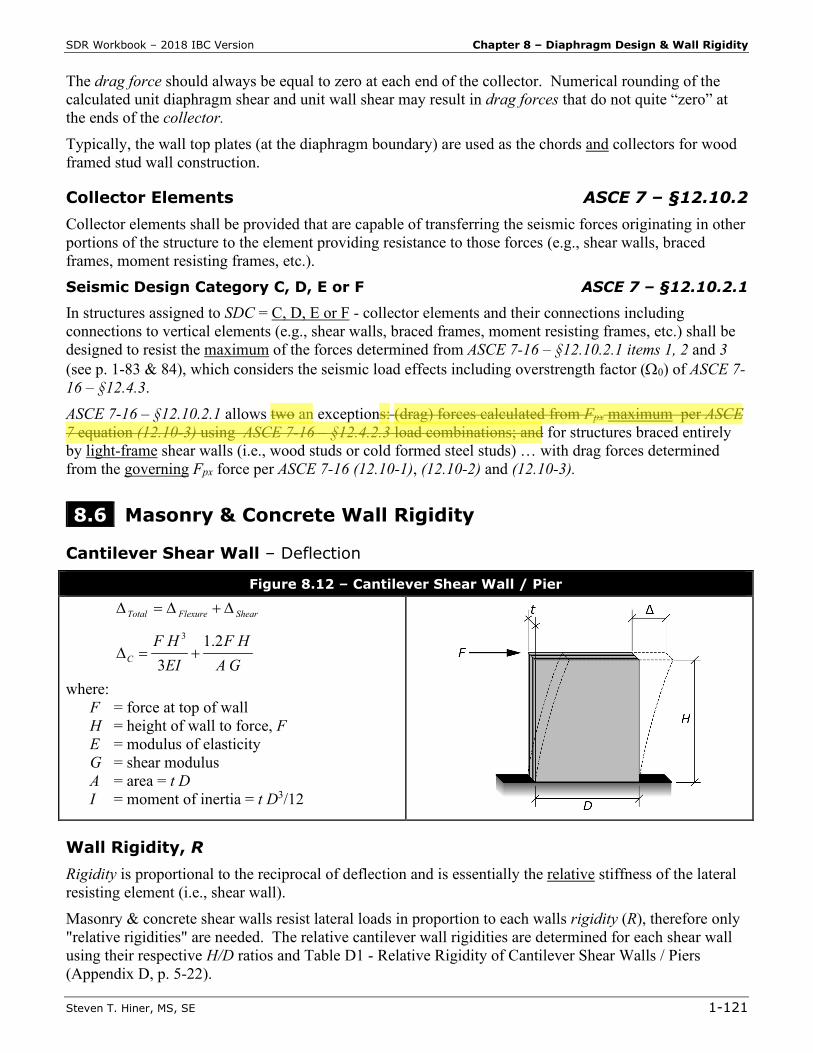
Figure 8.12 – Cantilever Shear Wall / Pier
ShearFlexureTotal ∆+∆=∆
GA
HFEIHF
C
2.13
3
+=∆
where: F = force at top of wall H = height of wall to force, F E = modulus of elasticity G = shear modulus A = area = t D I = moment of inertia = t D3/12
Wall Rigidity, R Rigidity is proportional to the reciprocal of deflection and is essentially the relative stiffness of the lateral resisting element (i.e., shear wall). Masonry & concrete shear walls resist lateral loads in proportion to each walls rigidity (R), therefore only "relative rigidities" are needed. The relative cantilever wall rigidities are determined for each shear wall using their respective H/D ratios and Table D1 - Relative Rigidity of Cantilever Shear Walls / Piers (Appendix D, p. 5-22).
Chapter 8 – Diaphragm Design & Wall Rigidity SDR Workbook – 2018 IBC Version
1-128 Steven T. Hiner, MS, SE
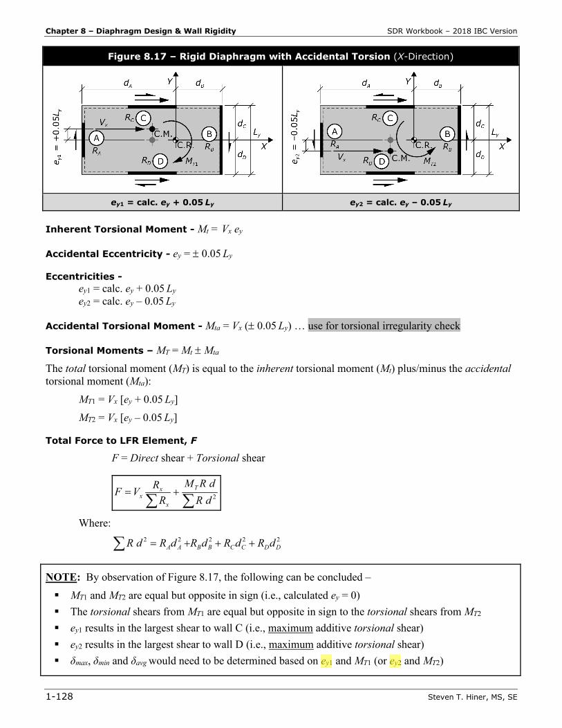
Figure 8.17 – Rigid Diaphragm with Accidental Torsion (X-Direction)
ey1 = calc. ey + 0.05 Ly ey2 = calc. ey – 0.05 Ly
Inherent Torsional Moment - Mt = Vx ey
Accidental Eccentricity - ey = ± 0.05 Ly
Eccentricities - ey1 = calc. ey + 0.05 Ly ey2 = calc. ey – 0.05 Ly
Accidental Torsional Moment - Mta = Vx (± 0.05 Ly) … use for torsional irregularity check
Torsional Moments – MT = Mt ± Mta
The total torsional moment (MT) is equal to the inherent torsional moment (Mt) plus/minus the accidental torsional moment (Mta): MT1 = Vx [ey + 0.05 Ly] MT2 = Vx [ey – 0.05 Ly] Total Force to LFR Element, F
F = Direct shear + Torsional shear
∑∑
+= 2 dRdRM
RRVF T
x
xx
Where:
22222DDCCBBAA dRdRdRdRdR +++=∑
NOTE: By observation of Figure 8.17, the following can be concluded – MT1 and MT2 are equal but opposite in sign (i.e., calculated ey = 0) The torsional shears from MT1 are equal but opposite in sign to the torsional shears from MT2 ey1 results in the largest shear to wall C (i.e., maximum additive torsional shear) ey2 results in the largest shear to wall D (i.e., maximum additive torsional shear) δmax, δmin and δavg would need to be determined based on ey1 and MT1 (or ey2 and MT2)
Chapter 12 – Structure Damage & Retrofit SDR Workbook – 2018 IBC Version
1-194 Steven T. Hiner, MS, SE
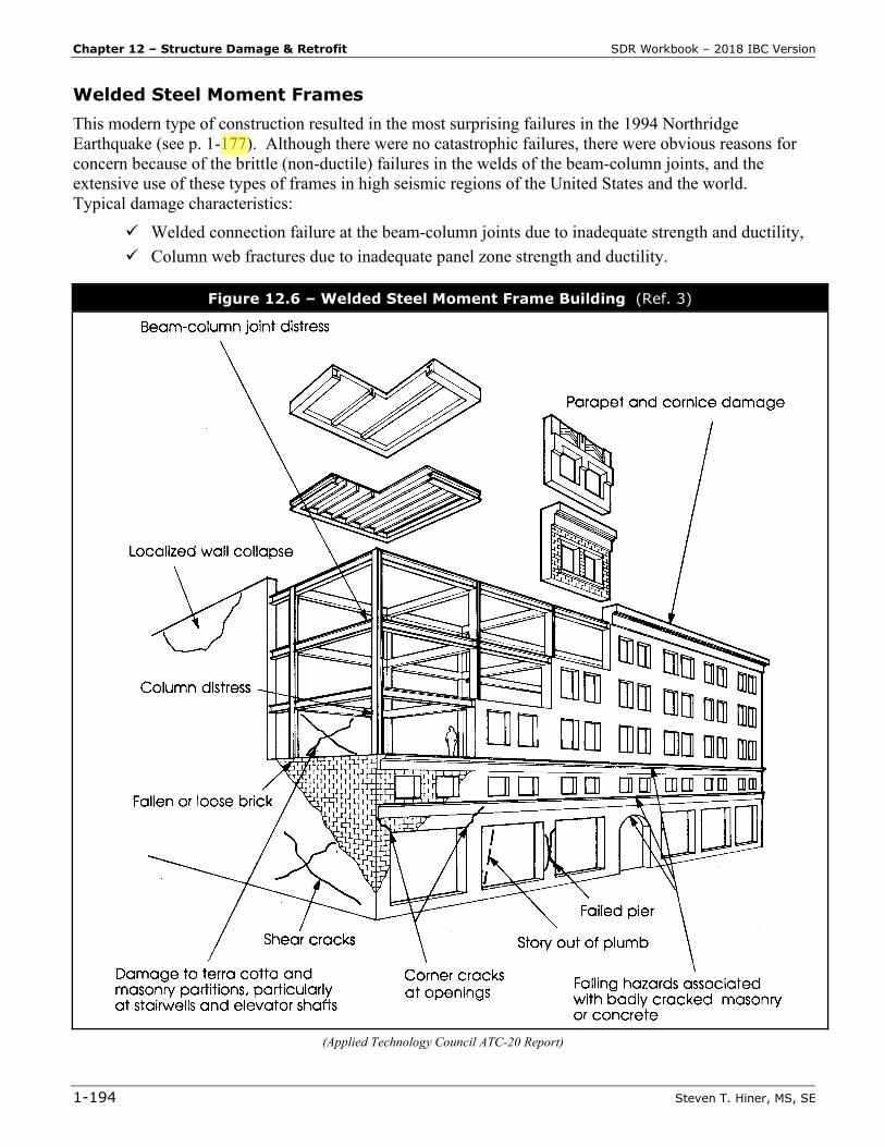
Welded Steel Moment Frames This modern type of construction resulted in the most surprising failures in the 1994 Northridge Earthquake (see p. 1-177). Although there were no catastrophic failures, there were obvious reasons for concern because of the brittle (non-ductile) failures in the welds of the beam-column joints, and the extensive use of these types of frames in high seismic regions of the United States and the world. Typical damage characteristics:
Welded connection failure at the beam-column joints due to inadequate strength and ductility, Column web fractures due to inadequate panel zone strength and ductility.
Figure 12.6 – Welded Steel Moment Frame Building (Ref. 3)
(Applied Technology Council ATC-20 Report)
Part 2 – Example Problems SDR Workbook – 2018 IBC Version
2-6 Steven T. Hiner, MS, SE
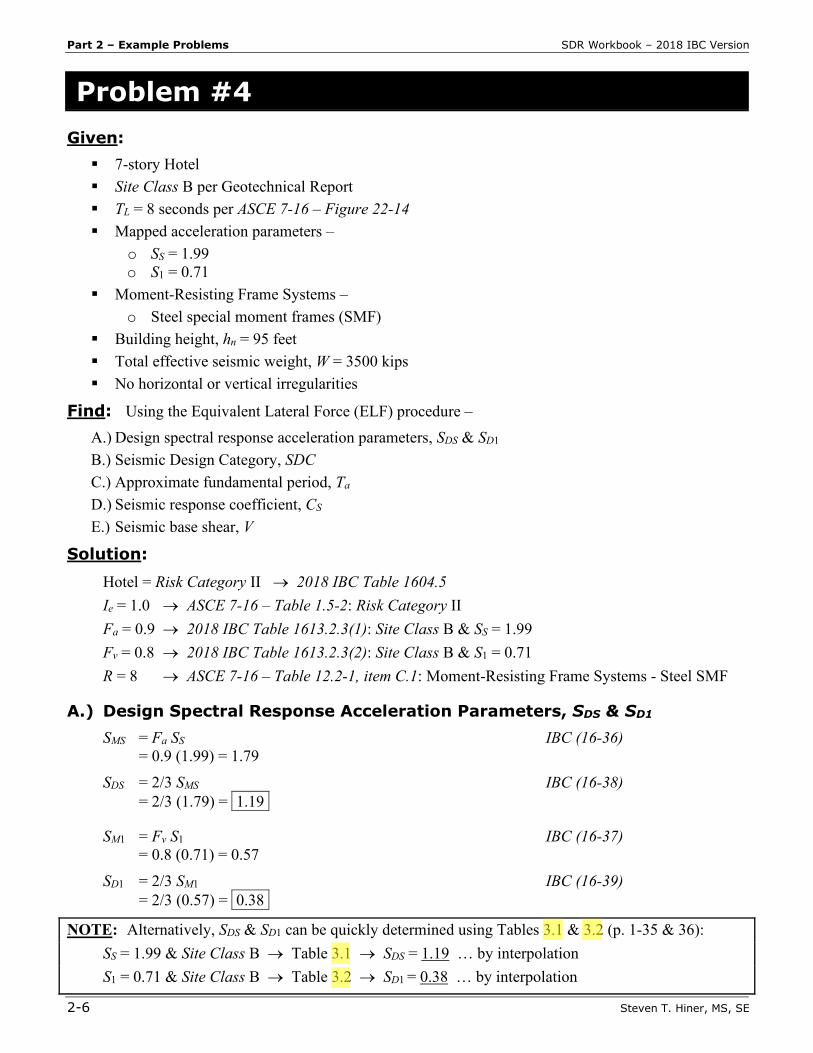
Problem #4 Given: 7-story Hotel Site Class B per Geotechnical Report TL = 8 seconds per ASCE 7-16 – Figure 22-14 Mapped acceleration parameters –
o SS = 1.99 o S1 = 0.71
Moment-Resisting Frame Systems – o Steel special moment frames (SMF)
Building height, hn = 95 feet Total effective seismic weight, W = 3500 kips No horizontal or vertical irregularities
Find: Using the Equivalent Lateral Force (ELF) procedure – A.) Design spectral response acceleration parameters, SDS & SD1 B.) Seismic Design Category, SDC C.) Approximate fundamental period, Ta D.) Seismic response coefficient, CS E.) Seismic base shear, V
Solution:
Hotel = Risk Category II → 2018 IBC Table 1604.5 Ie = 1.0 → ASCE 7-16 – Table 1.5-2: Risk Category II Fa = 0.9 → 2018 IBC Table 1613.2.3(1): Site Class B & SS = 1.99 Fv = 0.8 → 2018 IBC Table 1613.2.3(2): Site Class B & S1 = 0.71 R = 8 → ASCE 7-16 – Table 12.2-1, item C.1: Moment-Resisting Frame Systems - Steel SMF
A.) Design Spectral Response Acceleration Parameters, SDS & SD1 SMS = Fa SS IBC (16-36) = 0.9 (1.99) = 1.79 SDS = 2/3 SMS IBC (16-38) = 2/3 (1.79) = 1.19i
SM1 = Fv S1 IBC (16-37) = 0.8 (0.71) = 0.57 SD1 = 2/3 SM1 IBC (16-39) = 2/3 (0.57) = 0.38i
NOTE: Alternatively, SDS & SD1 can be quickly determined using Tables 3.1 & 3.2 (p. 1-35 & 36): SS = 1.99 & Site Class B → Table 3.1 → SDS = 1.19 … by interpolation S1 = 0.71 & Site Class B → Table 3.2 → SD1 = 0.38 … by interpolation
SDR Workbook – 2018 IBC Version Part 2 – Example Problems
Steven T. Hiner, MS, SE 2-9
SM1 = Fv S1 IBC (16-37) = 1.5 (0.48) = 0.72 SD1 = 2/3 SM1 IBC (16-39) = 2/3 (0.72) = 0.48i
NOTE: Alternatively, SDS & SD1 can be quickly determined using Tables 3.1 & 3.2 (p. 1-35 & 36):
SS = 1.22 & Site Class C → Table 3.1 → SDS = 0.98 … by interpolation S1 = 0.48 & Site Class C → Table 3.2 → SD1 = 0.48
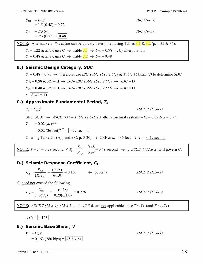
B.) Seismic Design Category, SDC
S1 = 0.48 < 0.75 → therefore, use IBC Table 1613.2.5(1) & Table 1613.2.5(2) to determine SDC
SDS = 0.98 & RC = II → 2018 IBC Table 1613.2.5(1) → SDC = D
SD1 = 0.48 & RC = II → 2018 IBC Table 1613.2.5(2) → SDC = D
∴ iSDC = Dii
C.) Approximate Fundamental Period, Ta
xnta hCT = ASCE 7 (12.8-7)
Steel SCBF → ASCE 7-16 – Table 12.8-2: all other structural systems – Ct = 0.02 & x = 0.75 Ta = 0.02 (hn)0.75
= 0.02 (36 feet)0.75 = 0.29 secondi
Or using Table C1 (Appendix C, p. 5-20) → CBF & hn = 36 feet → Ta = 0.29 second
NOTE: T = Ta = 0.29 second < 1 0.480.98
DS
DS
STS
= = = 0.49 second → ∴ ASCE 7 (12.8-2) will govern CS
D.) Seismic Response Coefficient, CS
)( e
DSS IR
SC = = (0.98)(6 1.0)
= 0.163 ← governs ASCE 7 (12.8-2)
CS need not exceed the following,
)(
1
e
DS IRT
SC = = (0.48)0.29(6 1.0)
= 0.276 ASCE 7 (12.8-3)
NOTE: ASCE 7 (12.8-4), (12.8-5), and (12.8-6) are not applicable since T < TS (and T << TL)
∴CS = 0.163i
E.) Seismic Base Shear, V V = CS W ASCE 7 (12.8-1) = 0.163 (280 kips) = 45.6 kipsi
SDR Workbook – 2018 IBC Version Part 2 – Example Problems
Steven T. Hiner, MS, SE 2-11
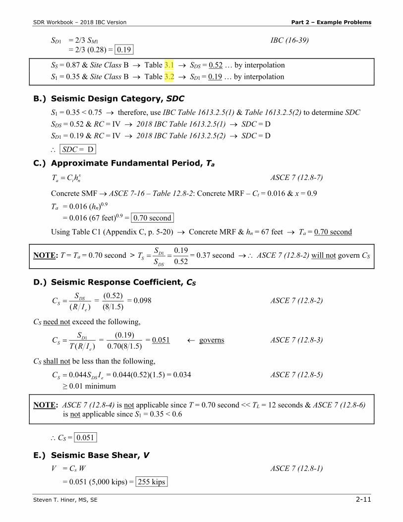
SD1 = 2/3 SM1 IBC (16-39) = 2/3 (0.28) = 0.19i
SS = 0.87 & Site Class B → Table 3.1 → SDS = 0.52 … by interpolation S1 = 0.35 & Site Class B → Table 3.2 → SD1 = 0.19 … by interpolation
B.) Seismic Design Category, SDC
S1 = 0.35 < 0.75 → therefore, use IBC Table 1613.2.5(1) & Table 1613.2.5(2) to determine SDC SDS = 0.52 & RC = IV → 2018 IBC Table 1613.2.5(1) → SDC = D SD1 = 0.19 & RC = IV → 2018 IBC Table 1613.2.5(2) → SDC = D
∴ iSDC = Dii
C.) Approximate Fundamental Period, Ta
xnta hCT = ASCE 7 (12.8-7)
Concrete SMF → ASCE 7-16 – Table 12.8-2: Concrete MRF – Ct = 0.016 & x = 0.9 Ta = 0.016 (hn)0.9 = 0.016 (67 feet)0.9 = 0.70 secondi
Using Table C1 (Appendix C, p. 5-20) → Concrete MRF & hn = 67 feet → Ta = 0.70 second
NOTE: T = Ta = 0.70 second > 1 0.190.52
DS
DS
STS
= = = 0.37 second → ∴ ASCE 7 (12.8-2) will not govern CS
D.) Seismic Response Coefficient, CS
)( e
DSS IR
SC = = (0.52)(8 1.5)
= 0.098 ASCE 7 (12.8-2)
CS need not exceed the following,
)(
1
e
DS IRT
SC = = (0.19)0.70(8 1.5)
= 0.051 ← governs ASCE 7 (12.8-3)
CS shall not be less than the following,
eDSS ISC 044.0= = 0.044(0.52)(1.5) = 0.034 ASCE 7 (12.8-5) ≥ 0.01 minimum
NOTE: ASCE 7 (12.8-4) is not applicable since T = 0.70 second << TL = 12 seconds & ASCE 7 (12.8-6) is not applicable since S1 = 0.35 < 0.6
∴CS = 0.051i
E.) Seismic Base Shear, V V = Cs W ASCE 7 (12.8-1)
= 0.051 (5,000 kips) = 255 kipsi
SDR Workbook – 2018 IBC Version Part 2 – Example Problems
Steven T. Hiner, MS, SE 2-13
SDS = 2/3 SMS IBC (16-38) = 2/3 (1.74) = 1.16i
SM1 = Fv S1 IBC (16-37) = 1.72 (0.58) = 1.00
SD1 = 2/3 SM1 IBC (16-39) = 2/3 (1.00) = 0.67i
SS = 1.45 & Site Class D (default) → Table 3.1 → SDS = 1.16 S1 = 0.58 & Site Class D (default) → Table 3.2 → SD1 = 0.67
B.) Seismic Design Category, SDC
S1 = 0.58 < 0.75 → therefore, use IBC Table 1613.2.5(1) & Table 1613.2.5(2) to determine SDC SDS = 1.16 & RC = II → 2018 IBC Table 1613.2.5(1) → SDC = D SD1 = 0.67 & RC = II → 2018 IBC Table 1613.2.5(2) → SDC = D
∴ iSDC = Dii
C.) Approximate Fundamental Period, Ta
xnta hCT = ASCE 7 (12.8-7)
WSP shear wall → ASCE 7-16 – Table 12.8-2: all other structural systems – Ct = 0.02 & x = 0.75 Ta = 0.02 (hn)0.75 = 0.02 (25 feet)0.75 = 0.22 secondi
Using Table C1 (Appendix C, p. 5-20) → Shear Walls & hn = 25 feet → Ta = 0.22 second
NOTE: T = Ta = 0.22 second < 1 0.671.16
DS
DS
STS
= = = 0.58 second → ∴ ASCE 7 (12.8-2) will govern CS
D.) Seismic Response Coefficient, CS
)( e
DSS IR
SC = = (1.16)(6.5 1.0)
= 0.179 ← governs ASCE 7 (12.8-2)
CS need not exceed the following,
)(
1
e
DS IRT
SC = = (0.67)0.22(6.5 1.0)
= 0.469 ASCE 7 (12.8-3)
NOTE: ASCE 7 (12.8-4), (12.8-5), and (12.8-6) are not applicable since T < TS (and T << TL)
∴CS = 0.179i
E.) Seismic Base Shear, V V = CS W ASCE 7 (12.8-1)
= 0.179 (135 kips) = 24.2 kipsi
SDR Workbook – 2018 IBC Version Part 2 – Example Problems
Steven T. Hiner, MS, SE 2-15
SS = 1.93 & Site Class E → Table 3.1 → SDS = 1.55 … by interpolation S1 = 0.77 & Site Class E → Table 3.2 → SD1 = 1.03 … by interpolation
B.) Seismic Design Category, SDC
S1 = 0.77 > 0.75 & RC = IV → 2018 IBC §1613.2.5 → SDC = F
∴ iSDC = Fi
C.) Approximate Fundamental Period, Ta
xnta hCT = ASCE 7 (12.8-7)
Dual System D.1 - steel EBF & steel SMF → ASCE 7-16 – Table 12.8-2: Ct = 0.03 & x = 0.75 Ta = 0.03 (hn)0.75
= 0.03 (60 feet)0.75 = 0.65 secondi
Using Table C1 (Appendix C, p. 5-20) → Dual System D.1 & hn = 60 feet → Ta = 0.65 second
NOTE: T = Ta = 0.65 second < 1 1.031.55
DS
DS
STS
= = = 0.66 second → ∴ ASCE 7 (12.8-2) will govern CS
D.) Seismic Response Coefficient, CS
)( e
DSS IR
SC = = (1.55)(8 1.5)
= 0.291 ← governs ASCE 7 (12.8-2)
CS need not exceed the following,
)(
1
e
DS IRT
SC = = (1.03)0.65(8 1.5)
= 0.298 ASCE 7 (12.8-3)
NOTE: ASCE 7 (12.8-4), (12.8-5), and (12.8-6) are not applicable since T < TS (and T << TL). Also, per ASCE 7-16 – §11.4.8 - Exception 3, a ground motion hazard analysis (in accordance with ASCE 7-16 – §21.2) is not required for structures on Site Class E sites with S1 ≥ 0.2 provided that the structures period T ≤ TS and the Equivalent Lateral Force (ELF) procedure is used for design. Therefore, if it was determined that T > TS … a ground motion hazard analysis would have been required.
∴CS = 0.291i
E.) Seismic Base Shear, V V = CS W ASCE 7 (12.8-1)
= 0.291 (24,000 kips) = 6980 kipsi
Part 2 – Example Problems SDR Workbook – 2018 IBC Version
2-44 Steven T. Hiner, MS, SE
Solution:
A.) N-S DIRECTION: L = 100′, d = 40′, CASE 3 L / d = 100′/40′ = 2.5:1 < 3:1 max. per SDPWS Table 4.2.4 (see Table 9.1, p. 1-139) for an
unblocked diaphragm → OK
1. Unit Roof Shear on lines A & B, νr VA = VB = ws L / 2 = (300 plf)(100′ / 2) = 15,000 lbs (SD/LRFD force level) roof νA = νB = 0.7 VA / d = 0.7 (15,000 lbs) / 40′ = 262 plfi (ASD force level)
2. Roof Diaphragm Nailing Try an unblocked diaphragm first (less costly than a blocked diaphragm) …
roof νA = 262 plf → SDPWS Table 4.2C - unblocked diaphragms (see Table 9.3, p. 1-144) → A - SEISMIC → 15/32″ WSP sheathing w/ 8d common (2½″ x 0.131″) @ 6″ o.c. edges, unblocked (CASE 3) tabulated nominal unit diaphragm shear νs = 360 plf
ASD ν = (tabulated nominalνs) / 2.0 = (360 plf) / 2.0 = 180 plf < 262 plf → NG!
Now try a blocked diaphragm …
roof νA = 262 plf → SDPWS Table 4.2A - blocked diaphragms (see Table 9.2, p. 1-143) → A - SEISMIC → 15/32″ WSP sheathing w/ 8d common (2½″ x 0.131″) @ 6″ o.c. edges, blocked (CASE 3) tabulated nominal unit diaphragm shearνs = 540 plf ASD ν = (tabulated nominalνs) / 2.0 = (540 plf) / 2.0 = 270 plf > 262 plf → OK
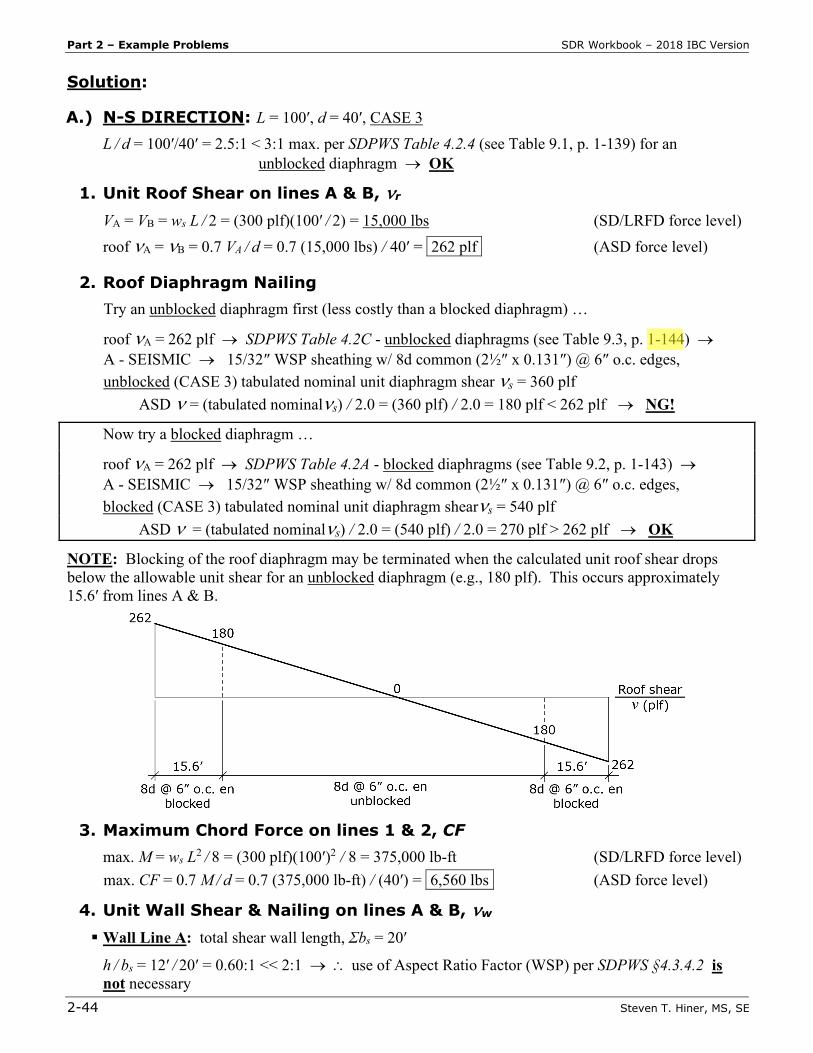
NOTE: Blocking of the roof diaphragm may be terminated when the calculated unit roof shear drops below the allowable unit shear for an unblocked diaphragm (e.g., 180 plf). This occurs approximately 15.6′ from lines A & B.
3. Maximum Chord Force on lines 1 & 2, CF
max. M = ws L2 / 8 = (300 plf)(100′)2 / 8 = 375,000 lb-ft (SD/LRFD force level)
max. CF = 0.7 M / d = 0.7 (375,000 lb-ft) / (40′) = 6,560 lbsi (ASD force level)
4. Unit Wall Shear & Nailing on lines A & B, νw Wall Line A: total shear wall length, Σbs = 20′
h / bs = 12′ / 20′ = 0.60:1 << 2:1 → ∴ use of Aspect Ratio Factor (WSP) per SDPWS §4.3.4.2 is not necessary
Part 3 – Multiple Choice Problems SDR Workbook – 2018 IBC Version
3-50 Steven T. Hiner, MS, SE
8.21 In a multi-story rigid diaphragm building, which of the following is distributed to the vertical elements of the seismic force-resisting system (SFRS) in proportion to their rigidities (i.e., stiffness)?
a. Base shear b. Lateral force at the level c. Drag force d. Story shear
8.22 The amplification of accidental torsional moment (Ax) per ASCE 7-16 – §12.8.4.3 applies to
buildings with a torsional irregularity or an extreme torsional irregularity assigned to Seismic Design Category:
a. B, C, D, E or F b. C, D, E or F c. D, E or F d. E or F
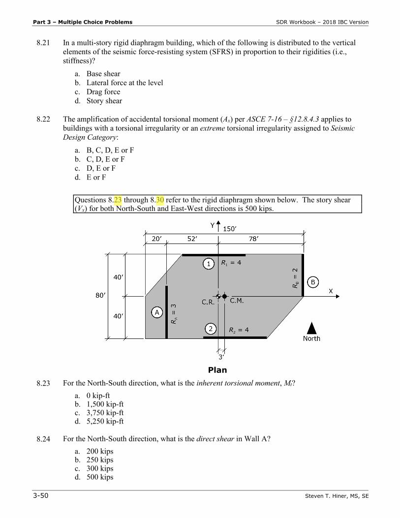
Questions 8.23 through 8.30 refer to the rigid diaphragm shown below. The story shear
(Vx) for both North-South and East-West directions is 500 kips.
Plan
8.23 For the North-South direction, what is the inherent torsional moment, Mt? a. 0 kip-ft b. 1,500 kip-ft c. 3,750 kip-ft d. 5,250 kip-ft
8.24 For the North-South direction, what is the direct shear in Wall A?
a. 200 kips b. 250 kips c. 300 kips d. 500 kips
Part 3 – Multiple Choice Problems SDR Workbook – 2018 IBC Version
3-52 Steven T. Hiner, MS, SE
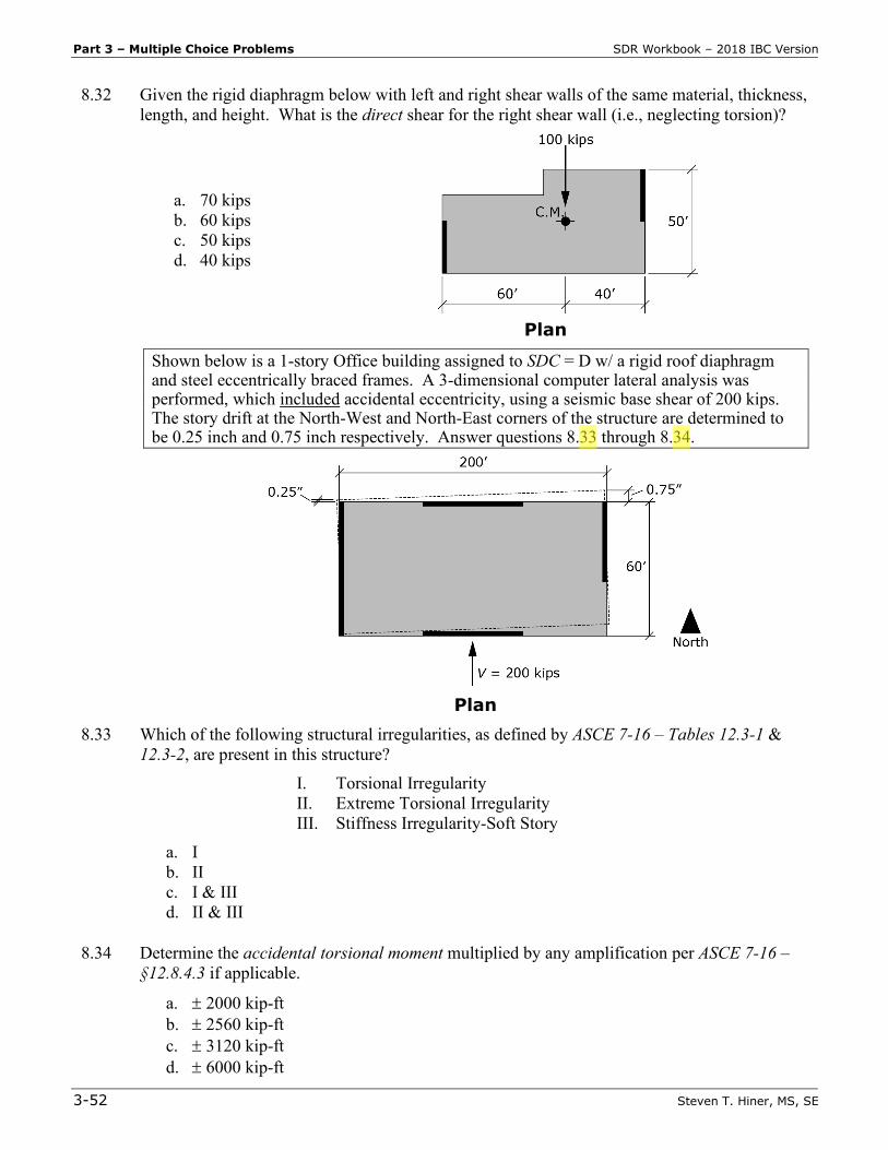
8.32 Given the rigid diaphragm below with left and right shear walls of the same material, thickness, length, and height. What is the direct shear for the right shear wall (i.e., neglecting torsion)?
a. 70 kips b. 60 kips c. 50 kips d. 40 kips
Plan
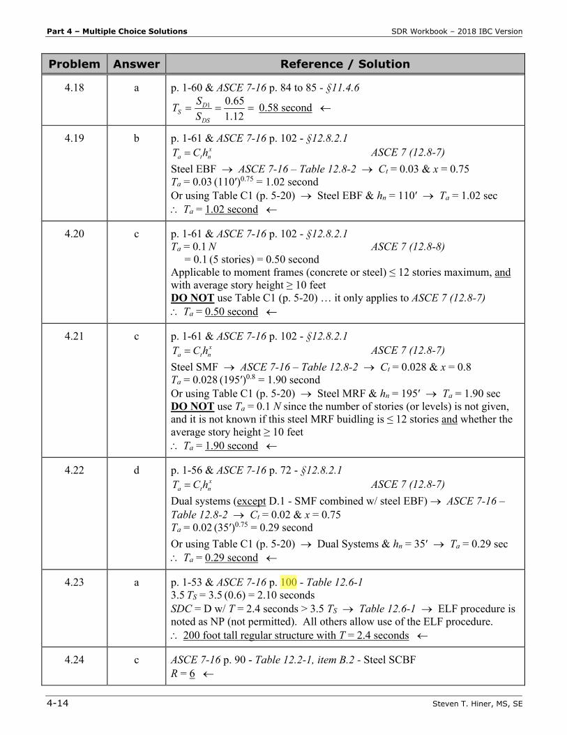
Shown below is a 1-story Office building assigned to SDC = D w/ a rigid roof diaphragm and steel eccentrically braced frames. A 3-dimensional computer lateral analysis was performed, which included accidental eccentricity, using a seismic base shear of 200 kips. The story drift at the North-West and North-East corners of the structure are determined to be 0.25 inch and 0.75 inch respectively. Answer questions 8.33 through 8.34.
Plan
8.33 Which of the following structural irregularities, as defined by ASCE 7-16 – Tables 12.3-1 & 12.3-2, are present in this structure?
I. Torsional Irregularity II. Extreme Torsional Irregularity
III. Stiffness Irregularity-Soft Story a. I b. II c. I & III d. II & III
8.34 Determine the accidental torsional moment multiplied by any amplification per ASCE 7-16 –
§12.8.4.3 if applicable.
a. ± 2000 kip-ft b. ± 2560 kip-ft c. ± 3120 kip-ft d. ± 6000 kip-ft
Part 4 – Multiple Choice Solutions SDR Workbook – 2018 IBC Version
4-14 Steven T. Hiner, MS, SE
Problem Answer Reference / Solution
4.18 a p. 1-60 & ASCE 7-16 p. 84 to 85 - §11.4.6
===12.165.01
DS
DS S
ST 0.58 second ←
4.19 b p. 1-61 & ASCE 7-16 p. 102 - §12.8.2.1 xnta hCT = ASCE 7 (12.8-7)
Steel EBF → ASCE 7-16 – Table 12.8-2 → Ct = 0.03 & x = 0.75 Ta = 0.03 (110′)0.75 = 1.02 second Or using Table C1 (p. 5-20) → Steel EBF & hn = 110′ → Ta = 1.02 sec ∴ Ta = 1.02 second ←
4.20 c p. 1-61 & ASCE 7-16 p. 102 - §12.8.2.1 Ta = 0.1 N ASCE 7 (12.8-8) = 0.1 (5 stories) = 0.50 second Applicable to moment frames (concrete or steel) ≤ 12 stories maximum, and with average story height ≥ 10 feet DO NOT use Table C1 (p. 5-20) … it only applies to ASCE 7 (12.8-7) ∴ Ta = 0.50 second ←
4.21 c p. 1-61 & ASCE 7-16 p. 102 - §12.8.2.1 xnta hCT = ASCE 7 (12.8-7)
Steel SMF → ASCE 7-16 – Table 12.8-2 → Ct = 0.028 & x = 0.8 Ta = 0.028 (195′)0.8 = 1.90 second Or using Table C1 (p. 5-20) → Steel MRF & hn = 195′ → Ta = 1.90 sec DO NOT use Ta = 0.1 N since the number of stories (or levels) is not given, and it is not known if this steel MRF buidling is ≤ 12 stories and whether the average story height ≥ 10 feet ∴ Ta = 1.90 second ←
4.22 d p. 1-56 & ASCE 7-16 p. 72 - §12.8.2.1 xnta hCT = ASCE 7 (12.8-7)
Dual systems (except D.1 - SMF combined w/ steel EBF) → ASCE 7-16 – Table 12.8-2 → Ct = 0.02 & x = 0.75 Ta = 0.02 (35′)0.75 = 0.29 second Or using Table C1 (p. 5-20) → Dual Systems & hn = 35′ → Ta = 0.29 sec ∴ Ta = 0.29 second ←
4.23 a p. 1-53 & ASCE 7-16 p. 100 - Table 12.6-1 3.5 TS = 3.5 (0.6) = 2.10 seconds SDC = D w/ T = 2.4 seconds > 3.5 TS → Table 12.6-1 → ELF procedure is noted as NP (not permitted). All others allow use of the ELF procedure. ∴ 200 foot tall regular structure with T = 2.4 seconds ←
4.24 c ASCE 7-16 p. 90 - Table 12.2-1, item B.2 - Steel SCBF R = 6 ←
SDR Workbook – 2018 IBC Version Part 4 – Multiple Choice Solutions
Steven T. Hiner, MS, SE 4-15
Problem Answer Reference / Solution
4.25 c ASCE 7-16 p. 90 - Table 12.2-1, item B.2 - Steel SCBF Ω0 = 2 ←
4.26 b ASCE 7-16 p. 90 & 91 - Table 12.2-1, item B.2 - Steel SCBF & footnote e SDC = D → hn = 160 ft BUT footnote e refers to ASCE 7-16 – §12.2.5.4 where 160 ft height limit may be increased to 240 ft provided items 1 and 2 are met. ∴ hn = 240 feet ←
4.27 d p. 1-61 & ASCE 7-16 p. 102 - §12.8.2.1 xnta hCT = ASCE 7 (12.8-7)
Ct = 0.02 & x = 0.75 → ASCE 7-16 – Table 12.8-2 (all others / steel SCBF) Ta = 0.02 (140′)0.75 = 0.81 second Or using Table C1 (p. 5-20) → CBF & hn = 140′ → Ta = 0.81 sec ∴ Ta = 0.8 second ←
4.28 c p. 1-47 & ASCE 7-16 p. 90 & 91 - Table 12.2-1 R coefficient is proportional to ductility (i.e., larger R = more ductile) Steel SCBF → Table 12.2-1, item B.2 - R = 6 Light-framed WSP shear walls → Table 12.2-1, item A.15/B.22 - R = 6½ / 7 Reinforced concrete SMF → Table 12.2-1, item C.5 - R = 8 Special reinforced masonry shear walls w/ steel SMF (Dual System) → Table 12.2-1, item D.10 - R = 5½ ∴ Special reinforced concrete moment frames (SMF) ←
4.29 c p. 1-47 - Ductility is the toughness of a material and represents its ability to permanently bend out of shape while still maintaining its structural integrity. Ductility is not directly related to flexibility or stiffness. ∴ Toughness ←
4.30 c p. 1-34 & ASCE 7-16 p. 90 to 92 - Table 12.2-1 The Seismic Design Category (SDC) of a structure is used to determine … seismic detailing requirements, etc. ∴ Seismic Design Category ←
4.31 a p. 1-47 - Figure 4.4 K = V / Δ → Largest K = “steepest” elastic curve (i.e., straightline portion) ∴ Shear Wall A is the largest stiffness ←
4.32 d p. 1-47 - Figure 4.4 K = V / Δ → Lowest K = “flattest” elastic curve (i.e., straightline portion) ∴ Shear Wall D has the lowest stiffness ←
4.33 b p. 1-47 - Figure 4.4 ∴ Shear Wall B would be the most ductile ←
SDR Workbook – 2018 IBC Version Part 4 – Multiple Choice Solutions
Steven T. Hiner, MS, SE 4-23
Problem Answer Reference / Solution
Σwi = w2 + w3 + w4 = 150 + 150 + 100 = 400 kips Fp2 = (ΣFi )(wp2 ) / (Σwi ) = (85.6 kips)(150 kips) / (400 kips) = 32.1 kips ←
4.79 a p. 1-63 to 64 - Vertical Distribution & ASCE 7-16 p. 102 - §12.8.3 VCF vxx = ASCE 7 (12.8-11)
∑=
= n
i
kii
kxx
vx
hw
hwC
1
ASCE 7 (12.8-12)
T ≤ 0.5 second → use k = 1 ∴ Triangular distribution of Fx ←
4.80 d p. 1-64 - Story Shear & ASCE 7-16 p. 102 - §12.8.4
∑=
=n
xiix FV ASCE 7 (12.8-13)
∴ Stair-stepped distribution of Vx ←
4.81 c p. 1-73 - Vertical Distribution & ASCE 7-16 p. 119 - §12.14.8.2
VWwF x
x = ASCE 7 (12.14-13)
∴ Uniform distribution of Fx ←
4.82 b p. 1-64 - Vertical Distribution & ASCE 7-16 p. 102 - §12.8.3 VCF vxx = ASCE 7 (12.8-11)
∑=
= n
i
kii
kxx
vx
hw
hwC
1
ASCE 7 (12.8-12)
T ≥ 2.5 second → use k = 2 ∴ Parabolic distribution of Fx ←
4.83 d p. 1-16 - Resonance, p. 1-32 - Site Class, and p. 1-61 - Period Determination Resonance (i.e., large seismic forces/base shear) is most likely to occur between a long period structure (i.e., 15-story steel moment frame – Ta ≈ 0.l N = 1.5 seconds) and long period soft soil. ∴ Site Class E (soft soil) ←
4.84 c p. 1-59 to 60 - Seismic Base Shear & ASCE 7-16 p. 101 - §12.8.1.1 R & Ie same for both Structure A & B SDS = 0.73 & SD1 = 0.30 TA = 0.35 second WB = 3 WA … find TB where VA = VB TS = SD1 / SDS = (0.30) / (0.73) = 0.41 second Structure A – TA = 0.35 second < TS = 0.41 second (continued)
SDR Workbook – 2018 IBC Version Part 4 – Multiple Choice Solutions
Steven T. Hiner, MS, SE 4-35
Problem Answer Reference / Solution
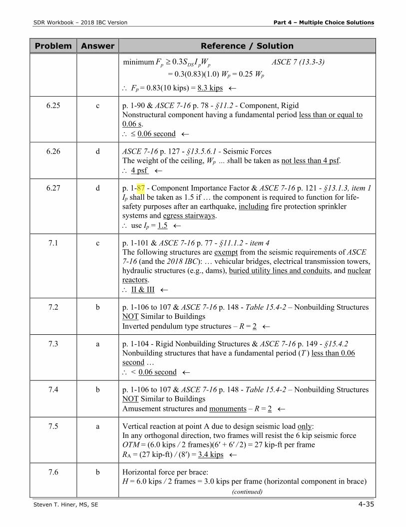
minimum ppDSp WISF 3.0≥ ASCE 7 (13.3-3) = 0.3(0.83)(1.0) Wp = 0.25 Wp
∴ Fp = 0.83(10 kips) = 8.3 kips ←
6.25 c p. 1-90 & ASCE 7-16 p. 78 - §11.2 - Component, Rigid Nonstructural component having a fundamental period less than or equal to 0.06 s. ∴ ≤ 0.06 second ←
6.26 d ASCE 7-16 p. 127 - §13.5.6.1 - Seismic Forces The weight of the ceiling, Wp ... shall be taken as not less than 4 psf. ∴ 4 psf ←
6.27 d p. 1-87 - Component Importance Factor & ASCE 7-16 p. 121 - §13.1.3, item 1 Ip shall be taken as 1.5 if … the component is required to function for life-safety purposes after an earthquake, including fire protection sprinkler systems and egress stairways. ∴ use Ip = 1.5 ←
7.1 c p. 1-101 & ASCE 7-16 p. 77 - §11.1.2 - item 4 The following structures are exempt from the seismic requirements of ASCE 7-16 (and the 2018 IBC): … vehicular bridges, electrical transmission towers, hydraulic structures (e.g., dams), buried utility lines and conduits, and nuclear reactors. ∴ II & III ←
7.2 b p. 1-106 to 107 & ASCE 7-16 p. 148 - Table 15.4-2 – Nonbuilding Structures NOT Similar to Buildings Inverted pendulum type structures – R = 2 ←
7.3 a p. 1-104 - Rigid Nonbuilding Structures & ASCE 7-16 p. 149 - §15.4.2 Nonbuilding structures that have a fundamental period (T ) less than 0.06 second … ∴ < 0.06 second ←
7.4 b p. 1-106 to 107 & ASCE 7-16 p. 148 - Table 15.4-2 – Nonbuilding Structures NOT Similar to Buildings Amusement structures and monuments – R = 2 ←
7.5 a Vertical reaction at point A due to design seismic load only: In any orthogonal direction, two frames will resist the 6 kip seismic force OTM = (6.0 kips / 2 frames)(6′ + 6′ / 2) = 27 kip-ft per frame RA = (27 kip-ft) / (8′) = 3.4 kips ←
7.6 b Horizontal force per brace: H = 6.0 kips / 2 frames = 3.0 kips per frame (horizontal component in brace)
(continued)
SDR Workbook – 2018 IBC Version Part 4 – Multiple Choice Solutions
Steven T. Hiner, MS, SE 4-45
Problem Answer Reference / Solution
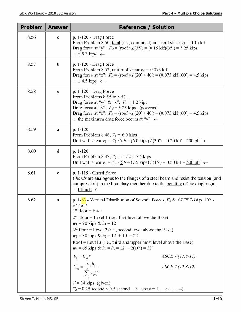
8.56 c p. 1-120 - Drag Force From Problem 8.50, total (i.e., combined) unit roof shear v2 = 0.15 klf Drag force at “y”: Fd = (roof v2)(35′) = (0.15 klf)(35′) = 5.25 kips ∴ ± 5.3 kips ←
8.57 b
p. 1-120 - Drag Force From Problem 8.52, unit roof shear vA = 0.075 klf Drag force at “z”: Fd = (roof vA)(20′ + 40′) = (0.075 klf)(60′) = 4.5 kips ∴ ± 4.5 kips ←
8.58 c p. 1-120 - Drag Force From Problems 8.55 to 8.57 - Drag force at “w” & “x”: Fd = 1.2 kips Drag force at “y”: Fd = 5.25 kips (governs) Drag force at “z”: Fd = (roof vA)(20′ + 40′) = (0.075 klf)(60′) = 4.5 kips ∴ the maximum drag force occurs at “y” ←
8.59 a p. 1-120 From Problem 8.46, V1 = 6.0 kips Unit wall shear v1 = V1 / ∑b = (6.0 kips) / (30′) = 0.20 klf = 200 plf ←
8.60 d p. 1-120 From Problem 8.47, V2 = V / 2 = 7.5 kips Unit wall shear v2 = V2 / ∑b = (7.5 kips) / (15′) = 0.50 klf = 500 plf ←
8.61 c p. 1-119 - Chord Force Chords are analogous to the flanges of a steel beam and resist the tension (and compression) in the boundary member due to the bending of the diaphragm. ∴ Chords ←
8.62 a p. 1-63 - Vertical Distribution of Seismic Forces, Fx & ASCE 7-16 p. 102 - §12.8.3 1st floor = Base 2nd floor = Level 1 (i.e., first level above the Base) w1 = 90 kips & h1 = 12′ 3rd floor = Level 2 (i.e., second level above the Base) w2 = 80 kips & h2 = 12′ + 10′ = 22′ Roof = Level 3 (i.e., third and upper most level above the Base) w3 = 65 kips & h3 = hn = 12′ + 2(10′) = 32′
VCF vxx = ASCE 7 (12.8-11)
∑=
= n
i
kii
kxx
vx
hw
hwC
1
ASCE 7 (12.8-12)
V = 24 kips (given) Ta = 0.25 second < 0.5 second → use k = 1 (continued)
Part 4 – Multiple Choice Solutions SDR Workbook – 2018 IBC Version
4-48 Steven T. Hiner, MS, SE
Problem Answer Reference / Solution
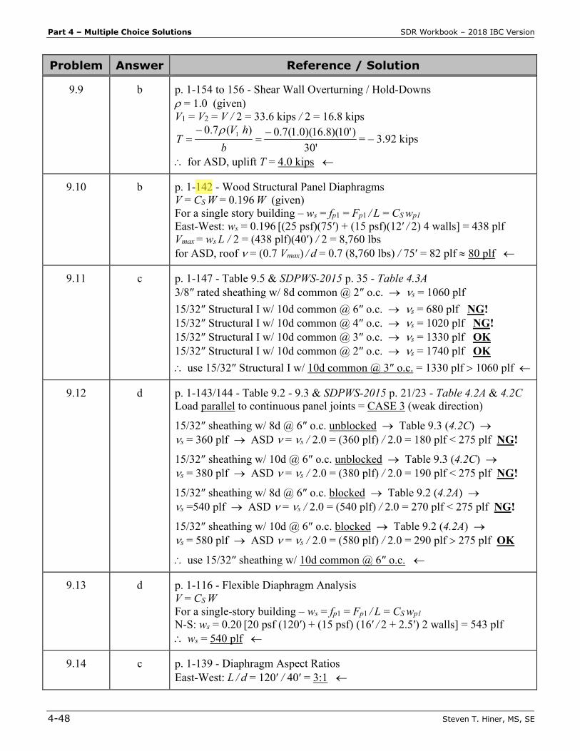
9.9 b p. 1-154 to 156 - Shear Wall Overturning / Hold-Downs ρ = 1.0 (given) V1 = V2 = V / 2 = 33.6 kips / 2 = 16.8 kips
'30)'10)(8.16)(0.1(7.0)(7.0 1 −
=−
=b
hVT
ρ= – 3.92 kips
∴ for ASD, uplift T = 4.0 kips ←
9.10 b p. 1-142 - Wood Structural Panel Diaphragms V = CS W = 0.196 W (given) For a single story building – ws = fp1 = Fp1 / L = CS wp1 East-West: ws = 0.196 [(25 psf)(75′) + (15 psf)(12′ / 2) 4 walls] = 438 plf Vmax = ws L / 2 = (438 plf)(40′) / 2 = 8,760 lbs for ASD, roof ν = (0.7 Vmax) / d = 0.7 (8,760 lbs) / 75′ = 82 plf ≈ 80 plf ←
9.11 c p. 1-147 - Table 9.5 & SDPWS-2015 p. 35 - Table 4.3A 3/8″ rated sheathing w/ 8d common @ 2″ o.c. → νs = 1060 plf 15/32″ Structural I w/ 10d common @ 6″ o.c. → νs = 680 plf NG! 15/32″ Structural I w/ 10d common @ 4″ o.c. → νs = 1020 plf NG! 15/32″ Structural I w/ 10d common @ 3″ o.c. → νs = 1330 plf OK 15/32″ Structural I w/ 10d common @ 2″ o.c. → νs = 1740 plf OK ∴ use 15/32″ Structural I w/ 10d common @ 3″ o.c. = 1330 plf > 1060 plf ←
9.12 d p. 1-143/144 - Table 9.2 - 9.3 & SDPWS-2015 p. 21/23 - Table 4.2A & 4.2C Load parallel to continuous panel joints = CASE 3 (weak direction)
15/32″ sheathing w/ 8d @ 6″ o.c. unblocked → Table 9.3 (4.2C) → νs = 360 plf → ASD ν = νs / 2.0 = (360 plf) / 2.0 = 180 plf < 275 plf NG!
15/32″ sheathing w/ 10d @ 6″ o.c. unblocked → Table 9.3 (4.2C) → νs = 380 plf → ASD ν = νs / 2.0 = (380 plf) / 2.0 = 190 plf < 275 plf NG!
15/32″ sheathing w/ 8d @ 6″ o.c. blocked → Table 9.2 (4.2A) → νs =540 plf → ASD ν = νs / 2.0 = (540 plf) / 2.0 = 270 plf < 275 plf NG!
15/32″ sheathing w/ 10d @ 6″ o.c. blocked → Table 9.2 (4.2A) → νs = 580 plf → ASD ν = νs / 2.0 = (580 plf) / 2.0 = 290 plf > 275 plf OK
∴ use 15/32″ sheathing w/ 10d common @ 6″ o.c. ←
9.13 d p. 1-116 - Flexible Diaphragm Analysis V = CS W For a single-story building – ws = fp1 = Fp1 / L = CS wp1 N-S: ws = 0.20 [20 psf (120′) + (15 psf) (16′ / 2 + 2.5′) 2 walls] = 543 plf ∴ ws = 540 plf ←
9.14 c p. 1-139 - Diaphragm Aspect Ratios East-West: L / d = 120′ / 40′ = 3:1 ←
Part 4 – Multiple Choice Solutions SDR Workbook – 2018 IBC Version
4-52 Steven T. Hiner, MS, SE
Problem Answer Reference / Solution
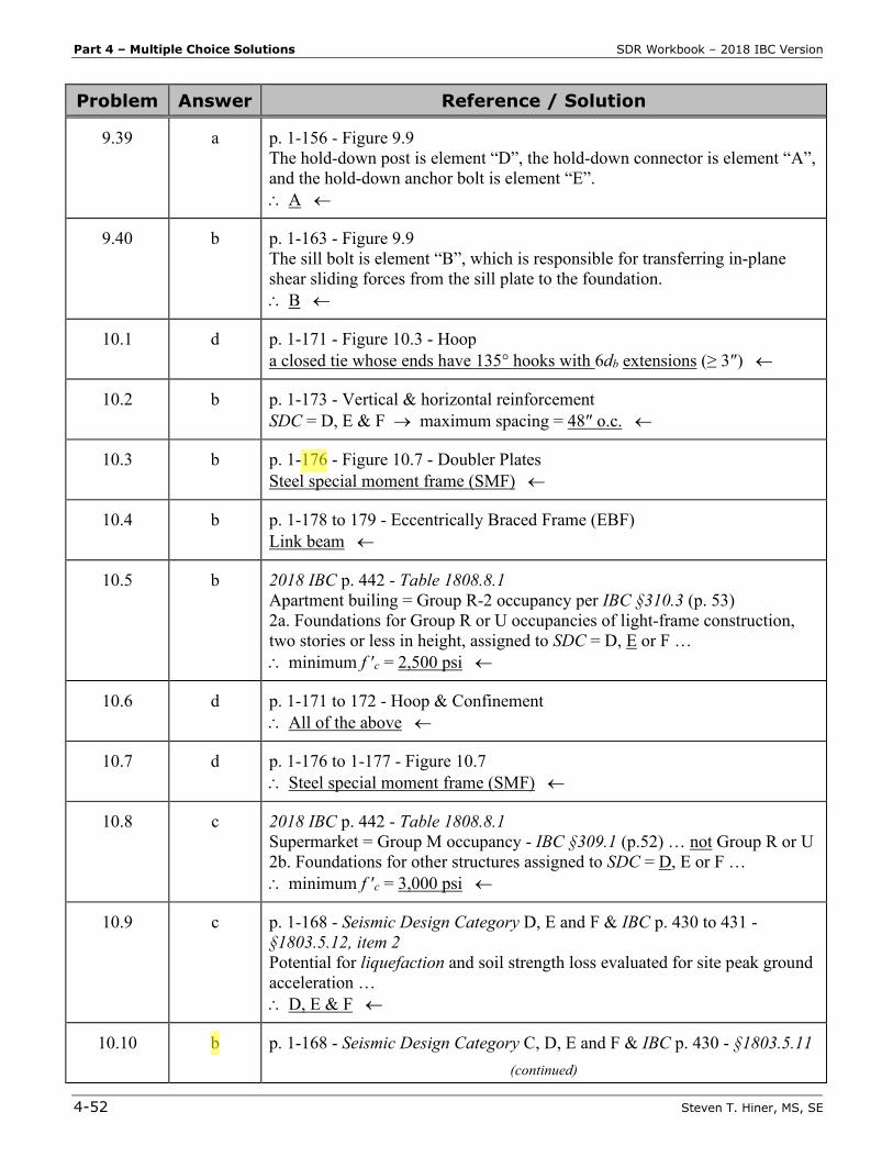
9.39 a p. 1-156 - Figure 9.9 The hold-down post is element “D”, the hold-down connector is element “A”, and the hold-down anchor bolt is element “E”. ∴ A ←
9.40 b p. 1-163 - Figure 9.9 The sill bolt is element “B”, which is responsible for transferring in-plane shear sliding forces from the sill plate to the foundation. ∴ B ←
10.1 d p. 1-171 - Figure 10.3 - Hoop a closed tie whose ends have 135° hooks with 6db extensions (≥ 3″) ←
10.2 b p. 1-173 - Vertical & horizontal reinforcement SDC = D, E & F → maximum spacing = 48″ o.c. ←
10.3 b p. 1-176 - Figure 10.7 - Doubler Plates Steel special moment frame (SMF) ←
10.4 b p. 1-178 to 179 - Eccentrically Braced Frame (EBF) Link beam ←
10.5 b 2018 IBC p. 442 - Table 1808.8.1 Apartment builing = Group R-2 occupancy per IBC §310.3 (p. 53) 2a. Foundations for Group R or U occupancies of light-frame construction, two stories or less in height, assigned to SDC = D, E or F … ∴ minimum f ′c = 2,500 psi ←
10.6 d p. 1-171 to 172 - Hoop & Confinement ∴ All of the above ←
10.7 d p. 1-176 to 1-177 - Figure 10.7 ∴ Steel special moment frame (SMF) ←
10.8 c 2018 IBC p. 442 - Table 1808.8.1 Supermarket = Group M occupancy - IBC §309.1 (p.52) … not Group R or U 2b. Foundations for other structures assigned to SDC = D, E or F … ∴ minimum f ′c = 3,000 psi ←
10.9 c p. 1-168 - Seismic Design Category D, E and F & IBC p. 430 to 431 - §1803.5.12, item 2 Potential for liquefaction and soil strength loss evaluated for site peak ground acceleration … ∴ D, E & F ←
10.10 b p. 1-168 - Seismic Design Category C, D, E and F & IBC p. 430 - §1803.5.11 (continued)
SDR Workbook – 2018 IBC Version Part 4 – Multiple Choice Solutions
Steven T. Hiner, MS, SE 4-53
Problem Answer Reference / Solution
A geotechnical investigation shall be conducted, and shall include an evaluation of all of the following potential geologic and seismic hazards - slope instability, liquefaction, total and differential settlement, surface fault displacement, etc. ∴ C, D, E & F ←
10.11 a p. 1-173 - Masonry & IBC p. 468 - §2106.1 The seismic design requirements of TMS 402-16 – Part 2: Chapter 7 shall apply to the design and construction of masonry … based on the structures Seismic Design Category. ∴ TMS 402-16 ←
10.12 a p. 1-176 - Seismic Design Category D, E or F & IBC p. 480 - §2205.2.1.2 (Structural steel SFRS of ) structures assigned to SDC = D, E or F shall be designed and detailed in accordance with AISC 341-16 – Seismic Provisions for Structural Steel Buildings … ∴ AISC 341-16 ←
10.13 c p. 1-177 - NOTE Following the January 17, 1994 Northridge Earthquake … the International Conference of Building Officials (ICBO) adopted an emergency code change to the 1994 Uniform Building Code (UBC). This code change omitted the pre-qualified connection (for welded steel moment frames) … ∴ 1994 Northridge, CA earthquake (Mw 6.7) ←
11.1 c p. 1-182 & 2018 IBC p. 416 - §1704.2 – Special inspections The owner or the owner’s agent, other than the contractor, shall employ one or more approved agencies to provide special inspections and tests … ∴ I & II ←
11.2 d p. 1-183 to 184 & 2018 IBC p. 416 to 422 - §1705 I. Masonry construction - §1705.4 II. Structural steel welding - §1705.2 III. Cast-in-place deep foundations - §1705.8 ∴ I, II & III ←
11.3 c p. 1-186 & 2018 IBC p. 418 - §1704.6 … the owner or the owner’s authorized agent shall employ a registered design professional to perform structural observations. Ideally, the structural observer should be ... the engineer (or architect) responsible for the structural design, etc. ∴ Civil engineer responsible for the structural design ←
11.4 b p. 1-187 & 2018 IBC p. 418 - §1704.6.2, item 1 & 2 Structural observations for seismic resistance shall be provided for those structures assigned to SDC = D, E or F where one or more of the following conditions exist:
(continued)
SDR Workbook – 2018 IBC Version Part 4 – Multiple Choice Solutions
Steven T. Hiner, MS, SE 4-61
Problem Answer Reference / Solution
14.5 a p. 1-206 - Structural Engineer Currently in California, a licensed Structural Engineer is required to design the structural systems of: Hospitals; public schools (primary, secondary & community college) – Field Act, Education Code §17302; etc. ∴ Public Schools ←
14.6 c p. 1-101 - Nonbuilding Structures & ASCE 7-16 p. 77 - §11.1.2 - item 4 The following structures are exmpt from the seismic requirements of this standard (i.e., ASCE 7-16) … and require special consideration of their response characterics … for which other regulations provide seismic criteria such as vehicular bridges, electrical transmission towers, etc. Therefore, the 2019 CBC and ASCE 7-16 are not applicable to vehicular bridges … ∴ CALTRANS Bridge Design Specifications ←
14.7 b p. 1-206 - Structural Engineer Currently in California, a licensed Structural Engineer is required to design the structural systems of: Hospitals; public schools; and buildings > 160 feet tall in Los Angeles County. 4-story Emergency Operations Center – none of the above … Civil PE okay 2-story Hospital … Civil PE NOT okay (SE required) 20-story Office Building with a Fire Station in the first story – not any of the above … Civil PE okay ∴ 2-story hospital ←
14.8 c p. 1-207 to 208 - Post-Earthquake Safety Evaluation The process of evaluating structures is based on the process and procedures described in the Applied Technology Council publication ATC-20: Procedures for Post-earthquake Safety Evaluation of Buildings. ∴ ATC-20 ←
14.9 b p. 1-209 - Post-Earthquake Safety Evaluation RESTRICTED USE (yellow) – building is damaged, may or may not be habitable; may be falling hazard present; may be damage to lateral force and/or vertical load systems, but still able to resist loads; occupancy is permitted per noted restrictions. ∴ Yellow placard ←
14.10 a p. 1-208 - Post-Earthquake Safety Evaluation All SAP evaluators must be deputized by the requesting jurisdiction to post official placards … and they cannot be hired by the building owners (i.e., they must be requested by the local jurisdiction). ∴ a ←
Part 5 – Appendix E SDR Workbook – 2018 IBC Version
5-38 Steven T. Hiner, MS, SE
1.47 Given a 110-foot tall, 9-story office building with special reinforced concrete shear walls (Building Frame System), SS = 2.20g, S1 = 0.79g, and Site Class B. Which ASCE 7-16 equation number will provide the governing seismic response coefficient ( CS )?
a. Equation (12.8-2) b. Equation (12.8-3) c. Equation (12.8-5) d. Equation (12.8-6)
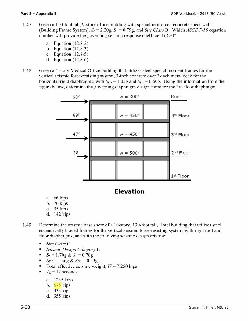
1.48 Given a 4-story Medical Office building that utilizes steel special moment frames for the
vertical seismic force-resisting system, 3-inch concrete over 3-inch metal deck for the horizontal rigid diaphragms, with SDS = 1.05g and SD1 = 0.60g. Using the information from the figure below, determine the governing diaphragm design force for the 3rd floor diaphragm.
a. 66 kips b. 76 kips c. 95 kips d. 142 kips
1.49 Determine the seismic base shear of a 10-story, 130-foot tall, Hotel building that utilizes steel
eccentrically braced frames for the vertical seismic force-resisting system, with rigid roof and floor diaphragms, and with the following seismic design criteria: Site Class C Seismic Design Category E SS = 1.70g & S1 = 0.78g SDS = 1.36g & SD1 = 0.73g Total effective seismic weight, W = 7,250 kips TL = 12 seconds
a. 1235 kips b. 575 kips c. 435 kips d. 355 kips
SDR Workbook – 2018 IBC Version Part 5 – Appendix E
Steven T. Hiner, MS, SE 5-39
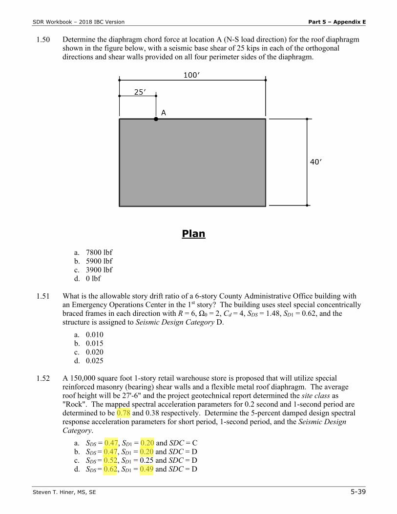
1.50 Determine the diaphragm chord force at location A (N-S load direction) for the roof diaphragm shown in the figure below, with a seismic base shear of 25 kips in each of the orthogonal directions and shear walls provided on all four perimeter sides of the diaphragm.
a. 7800 lbf b. 5900 lbf c. 3900 lbf d. 0 lbf
1.51 What is the allowable story drift ratio of a 6-story County Administrative Office building with
an Emergency Operations Center in the 1st story? The building uses steel special concentrically braced frames in each direction with R = 6, Ω0 = 2, Cd = 4, SDS = 1.48, SD1 = 0.62, and the structure is assigned to Seismic Design Category D.
a. 0.010 b. 0.015 c. 0.020 d. 0.025
1.52 A 150,000 square foot 1-story retail warehouse store is proposed that will utilize special
reinforced masonry (bearing) shear walls and a flexible metal roof diaphragm. The average roof height will be 27'-6" and the project geotechnical report determined the site class as "Rock". The mapped spectral acceleration parameters for 0.2 second and 1-second period are determined to be 0.78 and 0.38 respectively. Determine the 5-percent damped design spectral response acceleration parameters for short period, 1-second period, and the Seismic Design Category.
a. SDS = 0.47, SD1 = 0.20 and SDC = C b. SDS = 0.47, SD1 = 0.20 and SDC = D c. SDS = 0.52, SD1 = 0.25 and SDC = D d. SDS = 0.62, SD1 = 0.49 and SDC = D
Part 5 – Appendix F SDR Workbook – 2018 IBC Version
5-52 Steven T. Hiner, MS, SE
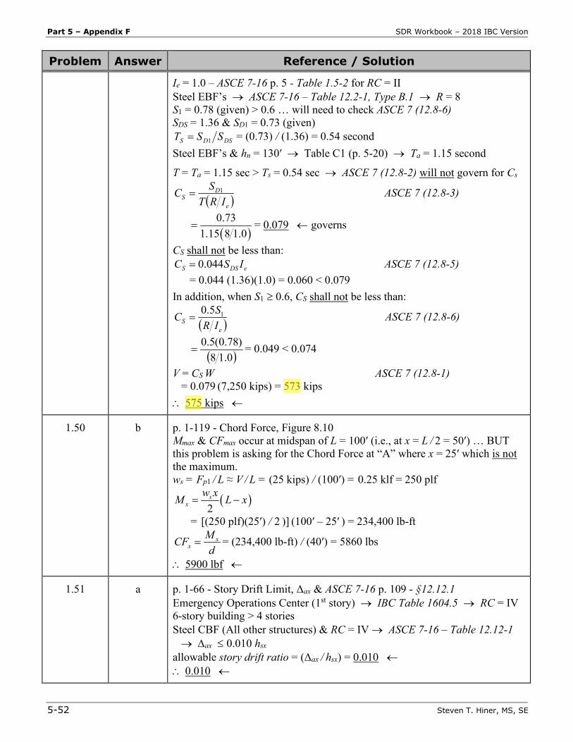
Problem Answer Reference / Solution
Ie = 1.0 – ASCE 7-16 p. 5 - Table 1.5-2 for RC = II Steel EBF’s → ASCE 7-16 – Table 12.2-1, Type B.1 → R = 8 S1 = 0.78 (given) > 0.6 … will need to check ASCE 7 (12.8-6) SDS = 1.36 & SD1 = 0.73 (given)
DSDS SST 1= = (0.73) / (1.36) = 0.54 second Steel EBF’s & hn = 130′ → Table C1 (p. 5-20) → Ta = 1.15 second
T = Ta = 1.15 sec > Ts = 0.54 sec → ASCE 7 (12.8-2) will not govern for Cs
( )e
DS IRT
SC 1= ASCE 7 (12.8-3)
( )
0.731.15 8 1.0
= = 0.079 ← governs
CS shall not be less than: eDSS ISC 044.0= ASCE 7 (12.8-5)
= 0.044 (1.36)(1.0) = 0.060 < 0.079 In addition, when S1 ≥ 0.6, CS shall not be less than:
( )eS IR
SC 15.0= ASCE 7 (12.8-6)
( )0.18)78.0(5.0
= = 0.049 < 0.074
V = CS W ASCE 7 (12.8-1) = 0.079 (7,250 kips) = 573 kips ∴ 575 kips ←
1.50 b p. 1-119 - Chord Force, Figure 8.10 Mmax & CFmax occur at midspan of L = 100′ (i.e., at x = L / 2 = 50′) … BUT this problem is asking for the Chord Force at “A” where x = 25′ which is not the maximum. ws = Fp1 / L ≈ V / L = (25 kips) / (100′) = 0.25 klf = 250 plf
( )2s
xw xM L x= −
= [(250 plf)(25′) / 2 )] (100′ – 25′ ) = 234,400 lb-ft
dMCF x
x = = (234,400 lb-ft) / (40′) = 5860 lbs
∴ 5900 lbf ←
1.51 a p. 1-66 - Story Drift Limit, Δax & ASCE 7-16 p. 109 - §12.12.1 Emergency Operations Center (1st story) → IBC Table 1604.5 → RC = IV 6-story building > 4 stories Steel CBF (All other structures) & RC = IV → ASCE 7-16 – Table 12.12-1 → ∆ax ≤ 0.010 hsx allowable story drift ratio = (Δax / hsx) = 0.010 ← ∴ 0.010 ←
SDR Workbook – 2018 IBC Version Part 5 – Appendix F
Steven T. Hiner, MS, SE 5-53
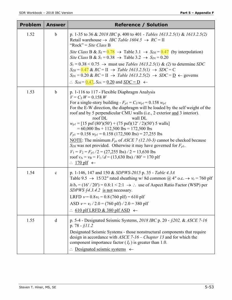
Problem Answer Reference / Solution
1.52 b p. 1-35 to 36 & 2018 IBC p. 400 to 401 - Tables 1613.2.5(1) & 1613.2.5(2) Retail warehouse → IBC Table 1604.5 → RC = II “Rock” = Site Class B Site Class B & SS = 0.78 → Table 3.1 → SDS = 0.47 (by interpolation) Site Class B & S1 = 0.38 → Table 3.2 → SD1 = 0.20 S1 = 0.38 < 0.75 → must use Tables 1613.2.5(1) & (2) to determine SDC SDS = 0.47 & RC = II → Table 1613.2.5(1) → SDC = C SD1 = 0.20 & RC = II → Table 1613.2.5(2) → SDC = D ← governs ∴ SDS = 0.47, SD1 = 0.20 and SDC = D ←
1.53 b p. 1-116 to 117 - Flexible Diaphragm Analysis V = CS W = 0.158 W For a single-story building - Fp1 = CS wp1 = 0.158 wp1 For the E-W direction, the diaphragm will be loaded by the self weight of the roof and by 5 perpendicular CMU walls (i.e., 2 exterior and 3 interior). roof DL wall DL wp1 = [15 psf (80′)(50′) + (75 psf)(12′ / 2)(50′) 5 walls] = 60,000 lbs + 112,500 lbs = 172,500 lbs Fp1 = 0.158 wp1 = 0.158 (172,500 lbs) = 27,255 lbs NOTE: The minimum Fpx of ASCE 7 (12.10-3) cannot be checked because SDS was not provided. Otherwise it may have governed for Fp1. V1 = V2 = Fp1 / 2 = (27,255 lbs) / 2 = 13,630 lbs roof vA = vB = V1 / d = (13,630 lbs) / 80′ = 170 plf ∴ 170 plf ←
1.54 c p. 1-146, 147 and 150 & SDPWS-2015 p. 35 - Table 4.3A Table 9.5 → 15/32″ rated sheathing w/ 8d common @ 4″ o.c. → νs = 760 plf h/bs = (16′ / 20′) = 0.8:1 < 2:1 → ∴ use of Aspect Ratio Factor (WSP) per SDPWS §4.3.4.2 is not necessary. LRFD ν = 0.8νs = 0.8 (760 plf) = 610 plf ASD ν = νs / 2.0 = (760 plf) / 2.0 = 380 plf ∴ 610 plf LRFD & 380 plf ASD ←
1.55 d p. 5-4 - Designated Seismic Systems, 2018 IBC p. 20 - §202, & ASCE 7-16 p. 78 - §11.2 Designated Seismic Systems - those nonstructural components that require design in accordance with ASCE 7-16 – Chapter 13 and for which the component importance factor ( Ip ) is greater than 1.0. ∴ Designated seismic systems ←
Part 5 – Appendix G SDR Workbook – 2018 IBC Version
5-58 Steven T. Hiner, MS, SE
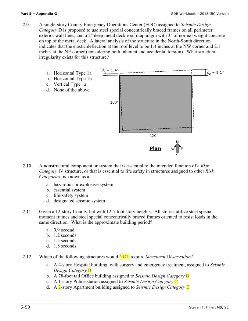
2.9 A single-story County Emergency Operations Center (EOC) assigned to Seismic Design Category D is proposed to use steel special concentrically braced frames on all perimeter exterior wall lines, and a 2" deep metal deck roof diaphragm with 3" of normal weight concrete on top of the metal deck. A lateral analysis of the structure in the North-South direction indicates that the elastic deflection at the roof level to be 1.4 inches at the NW corner and 2.1 inches at the NE corner (considering both inherent and accidental torsion). What structural irregularity exists for this structure?
a. Horizontal Type 1a b. Horizontal Type 1b c. Vertical Type 1a d. None of the above
2.10 A nonstructural component or system that is essential to the intended function of a Risk Category IV structure, or that is essential to life safety in structures assigned to other Risk Categories, is known as a:
a. hazardous or explosive system b. essential system c. life-safety system d. designated seismic system
2.11 Given a 12-story County Jail with 12.5-foot story heights. All stories utilize steel special
moment frames and steel special concentrically braced frames oriented to resist loads in the same direction. What is the approximate building period?
a. 0.9 second b. 1.2 seconds c. 1.5 seconds d. 1.8 seconds
2.12 Which of the following structures would NOT require Structural Observation?
a. A 4-story Hospital building, with surgery and emergency treatment, assigned to Seismic Design Category B
b. A 78-foot tall Office building assigned to Seismic Design Category B c. A 1-story Police station assigned to Seismic Design Category C d. A 2-story Apartment building assigned to Seismic Design Category E
SDR Workbook – 2018 IBC Version Part 5 – Appendix G
Steven T. Hiner, MS, SE 5-59
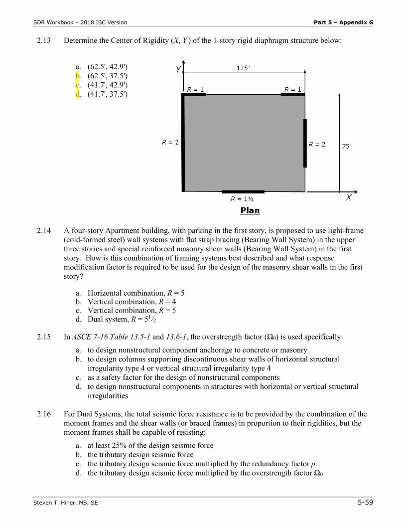
2.13 Determine the Center of Rigidity (X, Y ) of the 1-story rigid diaphragm structure below:
a. (62.5', 42.9') b. (62.5', 37.5') c. (41.7', 42.9') d. (41.7', 37.5')
2.14 A four-story Apartment building, with parking in the first story, is proposed to use light-frame (cold-formed steel) wall systems with flat strap bracing (Bearing Wall System) in the upper three stories and special reinforced masonry shear walls (Bearing Wall System) in the first story. How is this combination of framing systems best described and what response modification factor is required to be used for the design of the masonry shear walls in the first story?
a. Horizontal combination, R = 5 b. Vertical combination, R = 4 c. Vertical combination, R = 5 d. Dual system, R = 51/2
2.15 In ASCE 7-16 Table 13.5-1 and 13.6-1, the overstrength factor (Ω0) is used specifically:
a. to design nonstructural component anchorage to concrete or masonry b. to design columns supporting discontinuous shear walls of horizontal structural
irregularity type 4 or vertical structural irregularity type 4 c. as a safety factor for the design of nonstructural components d. to design nonstructural components in structures with horizontal or vertical structural
irregularities
2.16 For Dual Systems, the total seismic force resistance is to be provided by the combination of the moment frames and the shear walls (or braced frames) in proportion to their rigidities, but the moment frames shall be capable of resisting:
a. at least 25% of the design seismic force b. the tributary design seismic force c. the tributary design seismic force multiplied by the redundancy factor ρ d. the tributary design seismic force multiplied by the overstrength factor Ω0
Part 5 – Appendix G SDR Workbook – 2018 IBC Version
5-62 Steven T. Hiner, MS, SE
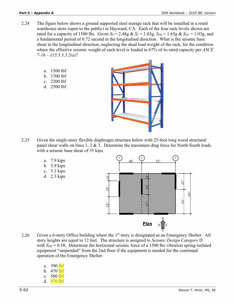
2.24 The figure below shows a ground supported steel storage rack that will be installed in a retail warehouse store (open to the public) in Hayward, CA. Each of the four rack levels shown are rated for a capacity of 1500 lbs. Given SS = 2.48g & S1 = 1.03g, SDS = 1.65g & SD1 = 1.03g, and a fundamental period of 0.72 second in the longitudinal direction. What is the seismic base shear in the longitudinal direction, neglecting the dead load weight of the rack, for the condition where the effective seismic weight of each level is loaded to 67% of its rated capacity per ASCE 7-16 – §15.5.3.3.2(a)?
a. 1500 lbf b. 1700 lbf c. 2200 lbf d. 2500 lbf
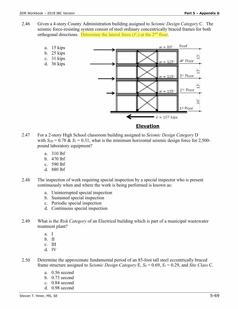
2.25 Given the single-story flexible diaphragm structure below with 25-foot long wood structural panel shear walls on lines 1, 2 & 3. Determine the maximum drag force for North-South loads with a seismic base shear of 35 kips.
a. 7.9 kips b. 5.9 kips c. 3.1 kips d. 2.3 kips
2.26 Given a 6-story Office building where the 1st story is designated as an Emergency Shelter. All story heights are equal to 12 feet. The structure is assigned to Seismic Design Category D with SDS = 0.58. Determine the horizontal seismic force of a 1500 lbs vibration spring-isolated equipment “suspended” from the 2nd floor if the equipment is needed for the continued operation of the Emergency Shelter.
a. 390 lbf b. 470 lbf c. 580 lbf d. 870 lbf
SDR Workbook – 2018 IBC Version Part 5 – Appendix G
Steven T. Hiner, MS, SE 5-69
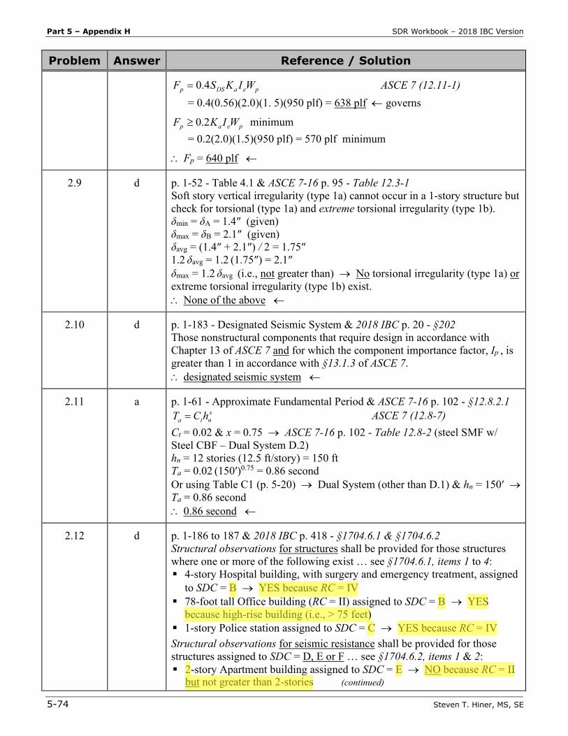
2.46 Given a 4-story County Administration building assigned to Seismic Design Category C. The seismic force-resisting system consist of steel ordinary concentrically braced frames for both orthogonal directions. Determine the lateral force (Fx) at the 2nd floor.
a. 15 kips b. 25 kips c. 31 kips d. 36 kips
2.47 For a 2-story High School classroom building assigned to Seismic Design Category D with SDS = 0.78 & S1 = 0.31, what is the minimum horizontal seismic design force for 2,500-pound laboratory equipment?
a. 310 lbf b. 470 lbf c. 590 lbf d. 880 lbf
2.48 The inspection of work requiring special inspection by a special inspector who is present
continuously when and where the work is being performed is known as: a. Uninterrupted special inspection b. Sustained special inspection c. Periodic special inspection d. Continuous special inspection
2.49 What is the Risk Category of an Electrical building which is part of a municipal wastewater
treatment plant? a. I b. II c. III d. IV
2.50 Determine the approximate fundamental period of an 85-foot tall steel eccentrically braced
frame structure assigned to Seismic Design Category E, SS = 0.69, S1 = 0.29, and Site Class C. a. 0.56 second b. 0.73 second c. 0.84 second d. 0.98 second
Part 5 – Appendix H SDR Workbook – 2018 IBC Version
5-74 Steven T. Hiner, MS, SE
Problem Answer Reference / Solution
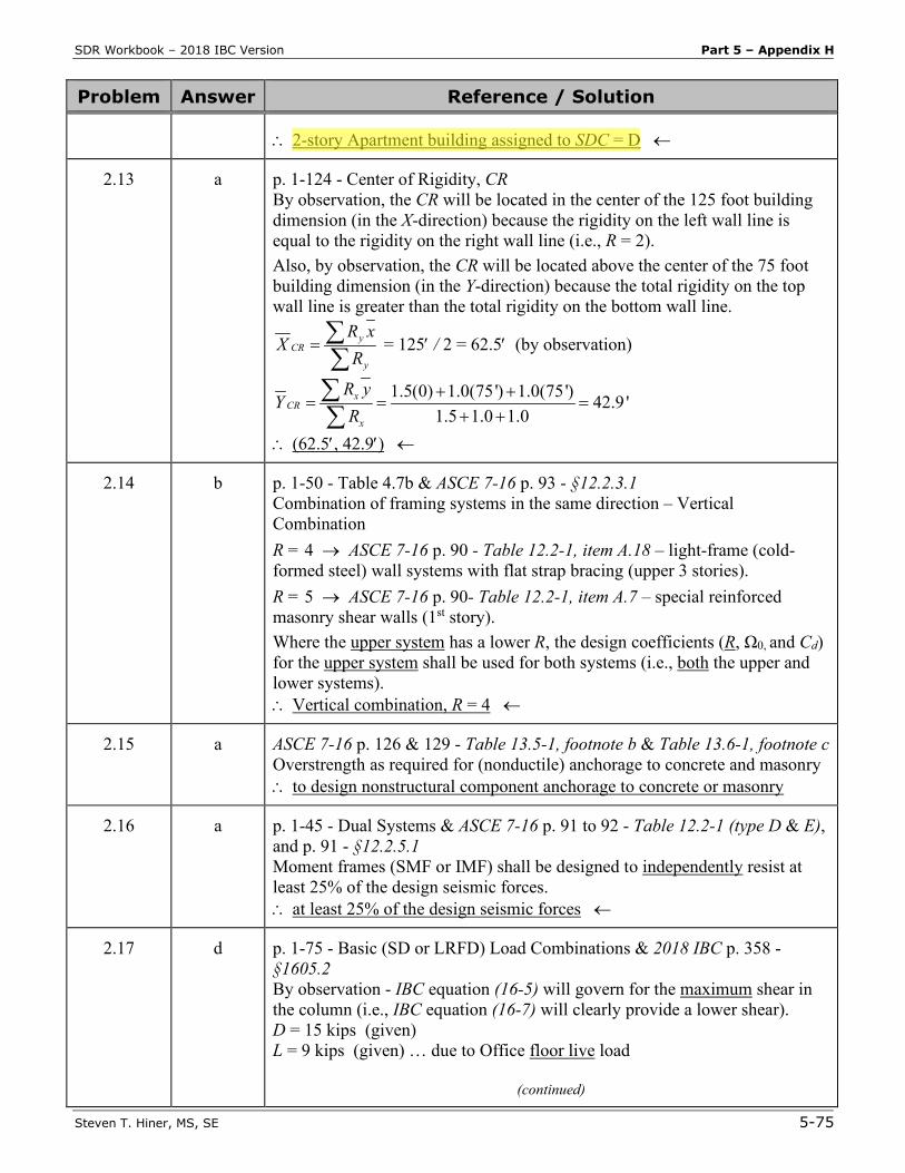
peaDSp WIKSF 4.0= ASCE 7 (12.11-1) = 0.4(0.56)(2.0)(1. 5)(950 plf) = 638 plf ← governs
peap WIKF 2.0≥ minimum = 0.2(2.0)(1.5)(950 plf) = 570 plf minimum
∴ Fp = 640 plf ←
2.9 d p. 1-52 - Table 4.1 & ASCE 7-16 p. 95 - Table 12.3-1 Soft story vertical irregularity (type 1a) cannot occur in a 1-story structure but check for torsional (type 1a) and extreme torsional irregularity (type 1b). δmin = δA = 1.4″ (given) δmax = δB = 2.1″ (given) δavg = (1.4″ + 2.1″) / 2 = 1.75″ 1.2 δavg = 1.2 (1.75″) = 2.1″ δmax = 1.2 δavg (i.e., not greater than) → No torsional irregularity (type 1a) or extreme torsional irregularity (type 1b) exist. ∴ None of the above ←
2.10 d p. 1-183 - Designated Seismic System & 2018 IBC p. 20 - §202 Those nonstructural components that require design in accordance with Chapter 13 of ASCE 7 and for which the component importance factor, Ip , is greater than 1 in accordance with §13.1.3 of ASCE 7. ∴ designated seismic system ←
2.11 a p. 1-61 - Approximate Fundamental Period & ASCE 7-16 p. 102 - §12.8.2.1 xnta hCT = ASCE 7 (12.8-7)
Ct = 0.02 & x = 0.75 → ASCE 7-16 p. 102 - Table 12.8-2 (steel SMF w/ Steel CBF – Dual System D.2) hn = 12 stories (12.5 ft/story) = 150 ft Ta = 0.02 (150′)0.75 = 0.86 second Or using Table C1 (p. 5-20) → Dual System (other than D.1) & hn = 150′ → Ta = 0.86 second ∴ 0.86 second ←
2.12 d p. 1-186 to 187 & 2018 IBC p. 418 - §1704.6.1 & §1704.6.2 Structural observations for structures shall be provided for those structures where one or more of the following exist … see §1704.6.1, items 1 to 4: 4-story Hospital building, with surgery and emergency treatment, assigned
to SDC = B → YES because RC = IV 78-foot tall Office building (RC = II) assigned to SDC = B → YES
because high-rise building (i.e., > 75 feet) 1-story Police station assigned to SDC = C → YES because RC = IV Structural observations for seismic resistance shall be provided for those structures assigned to SDC = D, E or F … see §1704.6.2, items 1 & 2: 2-story Apartment building assigned to SDC = E → NO because RC = II
but not greater than 2-stories (continued)
SDR Workbook – 2018 IBC Version Part 5 – Appendix H
Steven T. Hiner, MS, SE 5-75
Problem Answer Reference / Solution
∴ 2-story Apartment building assigned to SDC = D ←
2.13 a p. 1-124 - Center of Rigidity, CR By observation, the CR will be located in the center of the 125 foot building dimension (in the X-direction) because the rigidity on the left wall line is equal to the rigidity on the right wall line (i.e., R = 2). Also, by observation, the CR will be located above the center of the 75 foot building dimension (in the Y-direction) because the total rigidity on the top wall line is greater than the total rigidity on the bottom wall line.
∑∑=
y
yCR
RxR
X = 125′ / 2 = 62.5′ (by observation)
1.5(0) 1.0(75') 1.0(75') 42.9 '1.5 1.0 1.0
xCR
x
R yY
R+ +
= = =+ +
∑∑
∴ (62.5′, 42.9′) ←
2.14 b p. 1-50 - Table 4.7b & ASCE 7-16 p. 93 - §12.2.3.1 Combination of framing systems in the same direction – Vertical Combination R = 4 → ASCE 7-16 p. 90 - Table 12.2-1, item A.18 – light-frame (cold-formed steel) wall systems with flat strap bracing (upper 3 stories). R = 5 → ASCE 7-16 p. 90- Table 12.2-1, item A.7 – special reinforced masonry shear walls (1st story). Where the upper system has a lower R, the design coefficients (R, Ω0, and Cd) for the upper system shall be used for both systems (i.e., both the upper and lower systems). ∴ Vertical combination, R = 4 ←
2.15 a ASCE 7-16 p. 126 & 129 - Table 13.5-1, footnote b & Table 13.6-1, footnote c Overstrength as required for (nonductile) anchorage to concrete and masonry ∴ to design nonstructural component anchorage to concrete or masonry
2.16 a p. 1-45 - Dual Systems & ASCE 7-16 p. 91 to 92 - Table 12.2-1 (type D & E), and p. 91 - §12.2.5.1 Moment frames (SMF or IMF) shall be designed to independently resist at least 25% of the design seismic forces. ∴ at least 25% of the design seismic forces ←
2.17 d p. 1-75 - Basic (SD or LRFD) Load Combinations & 2018 IBC p. 358 - §1605.2 By observation - IBC equation (16-5) will govern for the maximum shear in the column (i.e., IBC equation (16-7) will clearly provide a lower shear). D = 15 kips (given) L = 9 kips (given) … due to Office floor live load
(continued)
SDR Workbook – 2018 IBC Version Part 5 – Appendix H
Steven T. Hiner, MS, SE 5-79
Problem Answer Reference / Solution
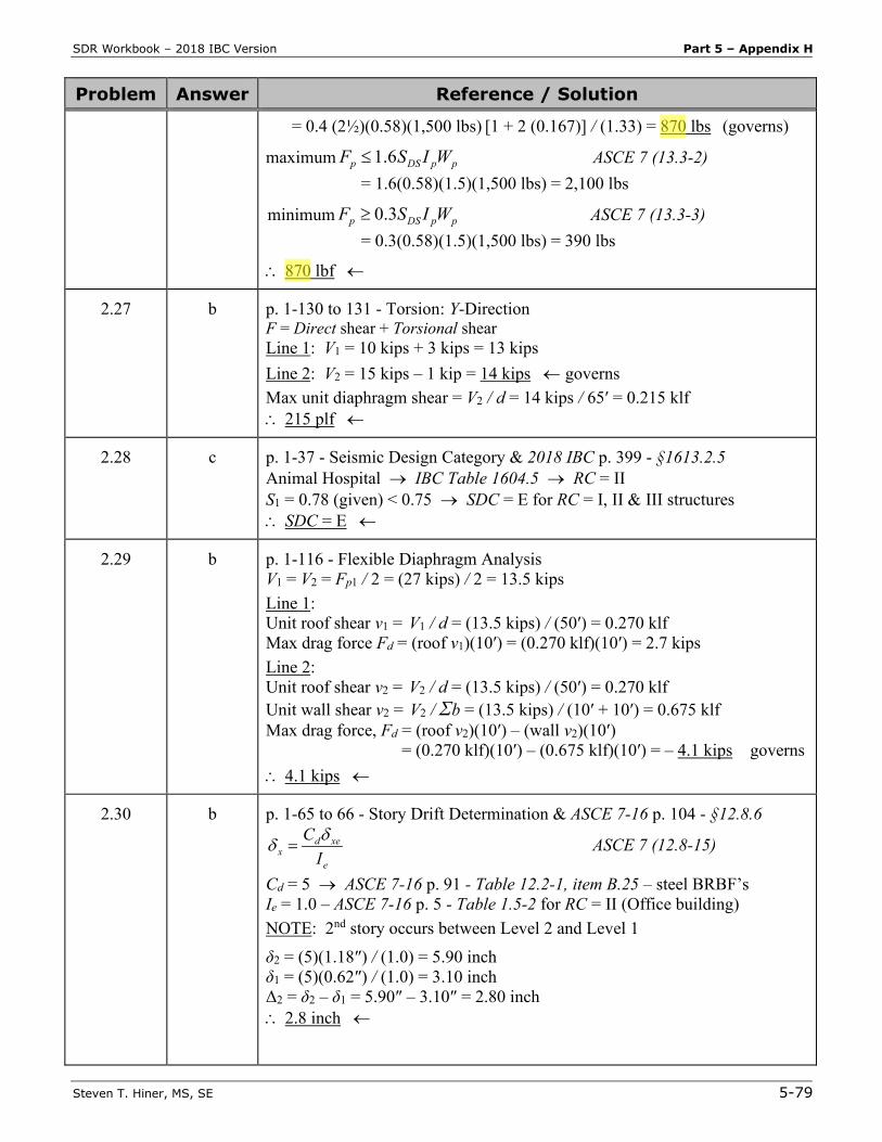
= 0.4 (2½)(0.58)(1,500 lbs) [1 + 2 (0.167)] / (1.33) = 870 lbs (governs)
maximum ppDSp WISF 6.1≤ ASCE 7 (13.3-2) = 1.6(0.58)(1.5)(1,500 lbs) = 2,100 lbs
minimum ppDSp WISF 3.0≥ ASCE 7 (13.3-3) = 0.3(0.58)(1.5)(1,500 lbs) = 390 lbs
∴ 870 lbf ←
2.27 b p. 1-130 to 131 - Torsion: Y-Direction F = Direct shear + Torsional shear Line 1: V1 = 10 kips + 3 kips = 13 kips Line 2: V2 = 15 kips – 1 kip = 14 kips ← governs Max unit diaphragm shear = V2 / d = 14 kips / 65′ = 0.215 klf ∴ 215 plf ←
2.28 c p. 1-37 - Seismic Design Category & 2018 IBC p. 399 - §1613.2.5 Animal Hospital → IBC Table 1604.5 → RC = II S1 = 0.78 (given) < 0.75 → SDC = E for RC = I, II & III structures ∴ SDC = E ←
2.29 b p. 1-116 - Flexible Diaphragm Analysis V1 = V2 = Fp1 / 2 = (27 kips) / 2 = 13.5 kips Line 1: Unit roof shear v1 = V1 / d = (13.5 kips) / (50′) = 0.270 klf Max drag force Fd = (roof v1)(10′) = (0.270 klf)(10′) = 2.7 kips Line 2: Unit roof shear v2 = V2 / d = (13.5 kips) / (50′) = 0.270 klf Unit wall shear v2 = V2 / Σb = (13.5 kips) / (10′ + 10′) = 0.675 klf Max drag force, Fd = (roof v2)(10′) – (wall v2)(10′) = (0.270 klf)(10′) – (0.675 klf)(10′) = – 4.1 kips governs ∴ 4.1 kips ←
2.30 b p. 1-65 to 66 - Story Drift Determination & ASCE 7-16 p. 104 - §12.8.6
e
xedx I
C δδ = ASCE 7 (12.8-15)
Cd = 5 → ASCE 7-16 p. 91 - Table 12.2-1, item B.25 – steel BRBF’s Ie = 1.0 – ASCE 7-16 p. 5 - Table 1.5-2 for RC = II (Office building) NOTE: 2nd story occurs between Level 2 and Level 1 δ2 = (5)(1.18″) / (1.0) = 5.90 inch δ1 = (5)(0.62″) / (1.0) = 3.10 inch Δ2 = δ2 – δ1 = 5.90″ – 3.10″ = 2.80 inch ∴ 2.8 inch ←