attachment 14, document 25402-011-mra-jd01-00001, rev
TRANSCRIPT
Attachment 14
Bechtel Power Corporation Document 25402-011 -MRA-JDOI -00001,"NSSS and BOP Controls Upgrade," Revision 0 (Non-Proprietary)
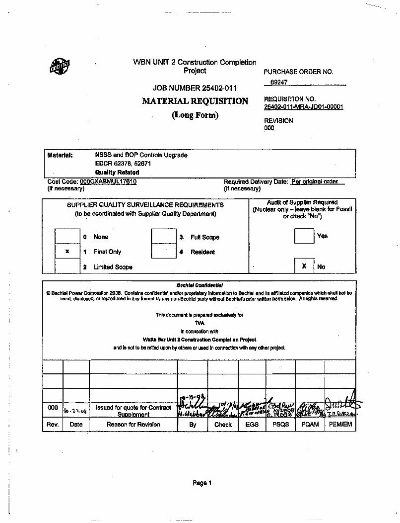
WBN UNIT 2 Construction CompletionProject
JOB NUMBER 25402-011
MATERIAL REQUISITION
(Long Form)
PURCHASE ORDER NO.
69247
REQUISITION NO.25402-01 1-MRA-JDOI-00001
REVISION000
Material: NSSS and SOP Controls UpgradeEDCR 62378, 62671Quality Related
Cost Code: 000CXARMUL1TBI0 Required Delivery Date: Per original order(if necessary) (if necessary)
SUPPLIER QUALITY SURVEILLANCE REQUIREMENTS Audit of Supplier Required
(to be coordinated with Supplier Quality Department) (Nuclear only - leave blank for Fossilor check "No")
0 None 3. Full Scope [] Yes
x I Final Only 4 Resident
2 Limited Scope 71X INo
OechWl Confldenfah0 Bechtel Power Corporatlon 2005. Contalns confidential andfor proprietary Information to Bechtel end Its offiliated companies which shal hot be
used. disclosed, or reproduced In any format by any non-Bechtel party without Bechters pitor w~itten permlsslon. All rights reserved.
ThI, document Is prepared hcluaboLveIy for
"VAIn conneoton wllh
WattS Bar Unit 2 Construetion Completion Projuot
and is not to be relied upon by othear or used In conneotlon with any other project
000 Issued for quote for Contract fu- - - Supplement H••6/ #0
Rev. Date Reason for Revision By Check EGS PSQS PQAM PEMIEM
Page I
-r
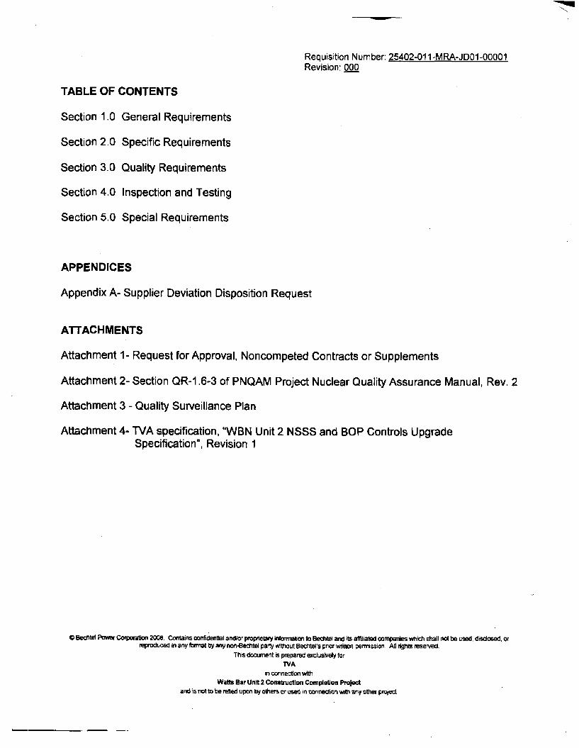
Requisition Number: 25402-011-MRA-JDOI-00001Revision: 000
TABLE OF CONTENTS
Section 1.0 General Requirements
Section 2.0 Specific Requirements
Section 3.0 Quality Requirements
Section 4.0 Inspection and Testing
Section 5.0 Special Requirements
APPENDICES
Appendix A- Supplier Deviation Disposition Request
ATTACHMENTS
Attachment 1- Request for Approval, Noncompeted Contracts or Supplements
Attachment 2- Section QR-1.6-3 of PNQAM Project Nuclear Quality Assurance Manual, Rev. 2
Attachment 3 - Quality Surveillance Plan
Attachment 4- TVA specification, "WBN Unit 2 NSSS and BOP Controls UpgradeSpecification", Revision 1
* Beentel Pomwr Corporation 2008. Contains ronfldentlal andlor proprietary informalon to Bechtel and its affiliated companies which shall not be used, discosed. orreproduced in any format by any non-Beitel party without Bechtel's pror written permission. All rights reserved.
This document is prepared exclusively for
TVAin connection with
Watts Bar Unit 2 Construction Completion Projectand is not to be relied upon by odhers or used in connection with any other projed,
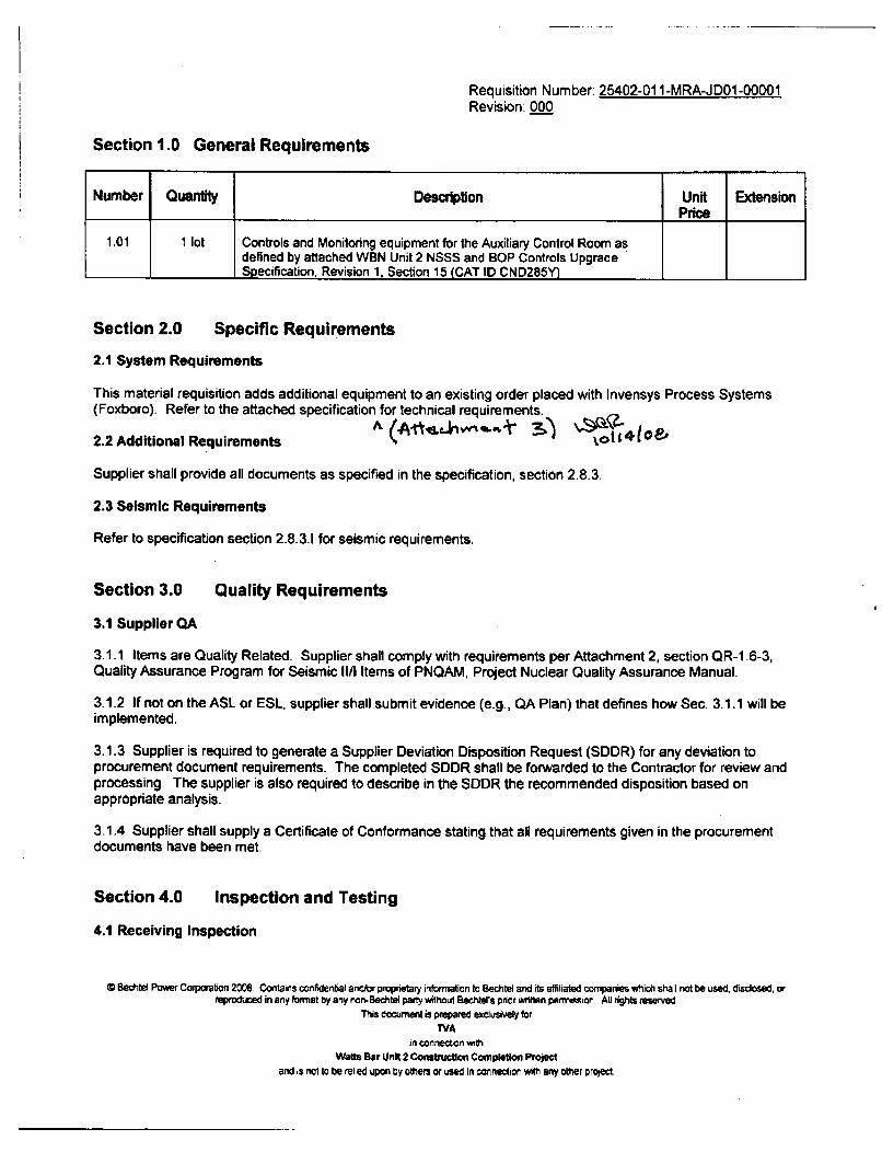
Requisition Number: 25402-011-MRA-JD01 -00001Revision. 000
Section 1.0 General Requirements
Number Quantity Description Unit ExtensionPrice
1.01 1 lot Controls and Monitoring equipment for the Auxiliary Control Room asdefined by attached WBN Unit 2 NSSS and BOP Controls UpgradeSpecification, Revision 1, Section 15 (CAT ID CND285Y)
Section 2.0 Specific Requirements
2.1 System Requirements
This material requisition adds additional equipment to an existing order placed with Invensys Process Systems(Foxboro). Refer to the attached specification for technical requirements.
2.2 Additional Requirements ( t n t4 t
Supplier shall provide all documents as specified in the specification, section 2.8.3.
2.3 Seismic Requirements
Refer to specification section 2.8.3.1 for seismic requirements.
Section 3.0 Quality Requirements
3.1 Supplier QA
3.1.1 Items are Quality Related. Supplier shall comply with requirements per Attachment 2, section QR-1 .6-3,Quality Assurance Program for Seismic Il/I Items of PNQAM, Project Nuclear Quality Assurance Manual.
3.1.2 If not on the ASL or ESL, supplier shall submit evidence (e.g., QA Plan) that defines how Sec. 3.1.1 will beimplemented.
3.1.3 Supplier is required to generate a Supplier Deviation Disposition Request (SDDR) for any deviation toprocurement document requirements. The completed SDDR shall be forwarded to the Contractor for review andprocessing. The supplier is also required to describe in the SODR the recommended disposition based onappropriate analysis.
3.1.4 Supplier shall supply a Certificate of Conformance stating that all requirements given in the procurementdocuments have been met.
Section 4.0 Inspection and Testing
4.1 Receiving Inspection
C Bechtel Power Corporation 20%8 Contains confidential and/or proprietary information to Bechtel and its affiliated companies which shall not be used. disclosed, orreproduced in any format by any non-Bechtel party without Bechters pnor written permission. All rights reserved
This document is prepared exclusively forTVA
in connection wthWatts Bar Unit 2 Construction Completion Project
and is not to be relied upon by others or used in connection with any other project.
Requisition Number: 25402-011-MRA-JDOI-00001Revision: 000
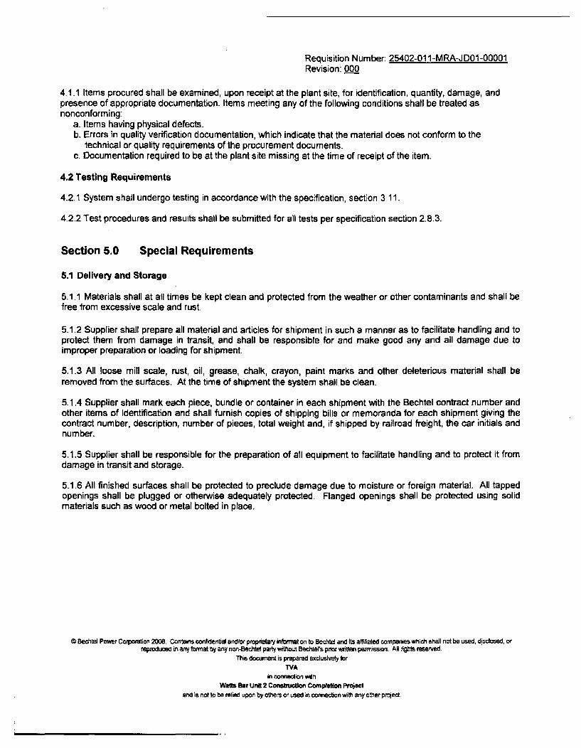
4.1.1 Items procured shall be examined, upon receipt at the plant site, for identification, quantity, damage, andpresence of appropriate documentation. Items meeting any of the following conditions shall be treated asnonconforming:
a. Items having physical defects.b. Errors in quality verification documentation, which indicate that the material does not conform to the
technical or quality requirements of the procurement documents.c. Documentation required to be at the plant site missing at the time of receipt of the item.
4.2 Testing Requirements
4.2.1 System shall undergo testing in accordance with the specification, section 3. 11.
4.2.2 Test procedures and results shall be submitted for all tests per specification section 2.8.3.
Section 5.0 Special Requirements
5.1 Delivery and Storage
5.1.1 Materials shall at all times be kept clean and protected from the weather or other contaminants and shall befree from excessive scale and rust.
5.1.2 Supplier shall prepare all material and articles for shipment in such a manner as to facilitate handling and toprotect them from damage in transit, and shall be responsible for and make good any and all damage due toimproper preparation or loading for shipment.
5.1.3 All loose min scale, rust, oil, grease, chalk, crayon, paint marks and other deleterious material shall beremoved from the surfaces. At the time of shipment the system shall be clean.
5.1.4 Supplier shall mark each piece, bundle or container in each shipment with the Bechtel contract number andother items of identification and shall furnish copies of shipping bills or memoranda for each shipment giving thecontract number, description, number of pieces, total weight and, if shipped by railroad freight, the car initials andnumber.
5.1.5 Supplier shall be responsible for the preparation of all equipment to facilitate handling and to protect it fromdamage in transit and storage.
5.1.6 All finished surfaces shall be protected to preclude damage due to moisture or foreign material. All tappedopenings shall be plugged or otherwise adequately protected. Flanged openings shall be protected using solidmaterials such as wood or metal bolted in place.
C Bechtel Power Corporation 2008. Contains confidential and/or proprietary information to Bechtel and its affiliated companies which shall not be used, disclosed. orreproduced in any format by any non-Bechtel party without Bechtel's prior wrtten permission. Al rights reserved
This document is prepared exclusively tor
TVAin connection with
Wats Bar Unit 2 construcilon Completion Projectand is not to be relied upon by others or used in connecton with any other project.

Requisition Number: 25402-011-MRA-JD01-00001Revision: 000
Appendix A
Supplier Deviation Disposition Request
C Bechtel Power CorporAon 2008. Contains confidential and/or proprietary information to Bechtel and ris afSiated companies which shall not be used, disclosed, orreproduced in any frmato by any non-Bechtel partyvAtuout Becnters pnorwntten permission. All rights reserved.
This document is prepared excusively for
IVAin connection with
Wadis Bar Unit 2 Cnenttction Completion Projectand is not to be retied upon by others or used in connection with any other project.
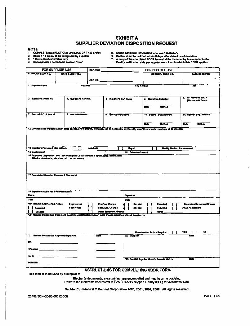
EXHIBIT ASUPPLIER DEVIATION DISPOSITION REQUEST
NOTES:1. COMPLETE INSTRUCTIONS ON BACK OF THIS SHEET2. 1iami 1-13 below to be completed by supplier3. * hnems, echtel emneoe only4. Nonapplicabte Items to be marked 'WA"
8. Attuh additional Infomatsion whenever n4eeaga6. Bech-l must be notfimd within l days after detection of deviaton7. A copy of the completed SOOD form s hall be included by the SupplieW in the
Quality verification data package for each item to which this SODN applies.
FOR SUPPUER USE PROJEcTFOR BECHTEL USESUPPLIEAmaiDnRO. DATE sUSM-rrTED JOSBE CHELS NO . OATE RMECEneD
1. Supplier Narme AdaI city £ sate Zip
2. Supplada Order No. 3. supp•a•' Pat No. 4 Suppiers Pat• Name a. Deviaes Detected 6. AH un s &0D1eiNumboro & Dolin)
0e112
7. Be~ch P.O. £ Rue. NMo 8. Beclhtl Pan No. a. Bchel Pant Name 10. BechtelsONotImod 11. Behtl Brig, Notilad
D IrdAxamd Dub Ie~~
12. Deviation De1licliplion (Anwr.h ýZ Ih*M.s iphtotoghlk oskefth. ftS. anecessay and Wdonly €lpntnity, andl mdal numberp as alp tilale)
113.Suyipawu Proposed Okpepealon. UwAa'e Repair fj Modifyr So~te Raapshwmetn14Vest upact 15. Schedue Ikepct6.IPropoaed Diapoeo end Tactnkal (pls Coseiflhedaue if applicbin) Juetiscalm:
Allach extra sheets, satkihn ae., a- neceassay.
117.Associsald Stpplier Dwuvuent Changele)
11$.6upleli' Auftiteed Representa*$, --
Nara 'I sinture
Title I,.- Oftc. • •
-20. l Dapoueon Stalefni Includng Juel#ca.lo lAmh e as sals, a alea hea , t tc. aas peaury),
Ooaabuciacos Actina Requited YE NO~ I ''21. RacJal)VipoatoApprevttgiabnev Dat. 22L Suppflau Date
REG:
'2& Becbtal Supplier Quality Repurmnuuteve DatePERtEW I
INSTRUCTIONS FOR COMPLETING SDDR FORMThis form is to be used by a supplier to:
Electronic documents, once printed, are uncontrolled and may become outdated.Refer to the electronic documents in TVA Business Support Ubrary (BSL) for curent revision.
Bechtel Confidentlal S Bechtel CorporaUon 2000. 2001, 2004, 2006. All rights reserved.
25402-30P-GQOG-00012-000 PAGE 1 of2
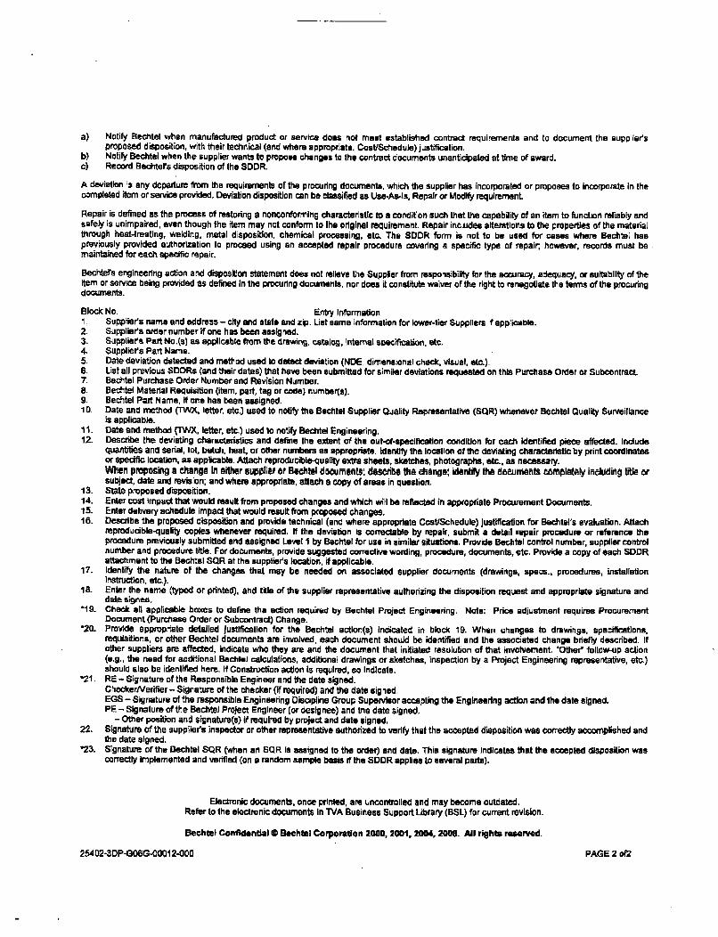
a) Notify Bechtel when manufactured product or service does root meet established contract requirements and to document the supplier'sproposed disposition, with their technical (and where appropriate, Cost/Schedule) justification.
b) Notify Bechtel when the supplier wants to propose changes to the contract documents unanticipated at time of award.c) Record Bechtel's disposition of the SDDR.
A deviation is any departure from the requirements of the procuring documents, which the supplier has Incorporated or proposes to incorporate in thecompleted item or service provided, Deviation disposition can be classified as Use-As-la, Repair or Modify requirement.
Repair is defined as the process of restoring a nonconforming characteristic to a condition such that the capability of an item to function reliably andsafely is unimpaired, even though the item may not conform to the original requirement. Repair includes alteratloos to the properties of the materialthrough heat-treating, welding, metal disposition, chemical processing, etc. The SDDR form is not to be used for cases where Bechtel haspreviously provided authorization to proceed using an accepted repair procedure covering a specific type of repair, however, records must bemaintained for each specific repair.
Bechtel's engineering action and disposition statement does not relieve the Supplier from responsibility for the accuracy, adequacy, or suitability of theitem or service being provided as defined in the procuring documents, nor does it constitute waiver of the right to renegotiate the terms of the procuringdocuments.
Block No. Entry Information1 Supplier's name and address - city and state and zip. List same information for lower-tier Suppliers if applicable.2. Suppliers order number If one has been assigned.3. Suppliers Part No.(s) as applicable from Ite drawing, catalog, Internal specification, etc.4. Suppliers Part Name.5. Date deviation detected and method used to dated deviation (NDE, dimensional check, visual, etc.)-6. List all previous SDDRs (and their dates) that have been submitted for similar deviations requested on this Purchase Order or Subcontract.7. Bechtel Purchase Order Number and Revision Number.8. Bechtel Material Requisition (item, part, tag or code) numbers),9. Bechtel Part Name, if one has been assigned.10. Date and method (TWX, letter, etc,) used Io notify the Bechtel Supplier Quality Representative (SQR) whenever Bechtel Quality Surveillance
is applicable.11. Date and method (TWX, letter, etc.) used to notify Bechtel Engineering.12. Describe the deviating characteristics and define the extent of the out-of-specification condition for each identified piece affected. Include
quantities and Serial, lot, batch, heat or other numbers as appropriate, Identify the location of the deviating characteristic by print coordinatesor specific location, as applicable. Attach reproducible-ulity extra sheets. sketches, photographs, etc., as necessary.When propoeing a change in either supplier or B•echl documenl&; desc-libl the cting.: id:-thiy d6,uJraemants cmrplftely in•clu-dg title orsubject, date and revision; and where appropriate, attach a copy of areas in question.
13. State proposed disposition.14. Enter cost impact that would result from proposed changes and which will be reflected in appropriate Procurement Documents.15. Enter delivery schedule Impact that would result from proposed changes.16. Describe the proposed disposition and provide technical (and where appropriate Cost/Schedule) justificatioin for Bechtel's evaluation. Attach
reproducible-quality copies whenever required. If the deviation is correctable by repair, submit a detail repair procedure or reference theprocedure previously submitted and assigned Level I by Bechtel for use in similar situations. Provide Bechtel control number, supplier controlnumber and procedure tie. For documents, provide suggested corrective wording, procedure, documents, etc. Provide a copy of each SDDRattachment to the Bechtel SOR at the supplier's location, if applicable.
17. Identify the nature of the changes that may be needed on associated supplier documents (drawings, apace., procedures, installationInstruction, etc.).
18. Enter the name (typed or printed), and title of the supplier representative authorizing the disposition request and appropriate signature anddate signed.
"19- Check all applicable boxes to define the action required by Bechtel Project Engineering. Note: Price adjustment requires ProcurementDocument (Purchase Order or Subcontract) Change.
"20. Provide appropriate detailed Justification for the Bechtel action(s) indicated in block 19. When changes to drawings, specifications,requilitions, or other Bechtel documents are involved, each document should be identified and the associated change briefly described. Ifother suppliers are aftfcted, indicate who they are and the document that initiated resolution of that involvement, 'Other' follow-up action(e.g., the need for additional Bechtel calculations, additional drawings or sketches, inspection by a Project Engineering representative, etc.)should also be identified here. If Construction action is required, so indicate.
21 . RE - Signature of the Responsible Engineer and the date signed.CheckerNerifier- Signature of the checker (If required) and the date signed,EGS - Signature of the responsible Engineering Discipline Group Supervisor accepting the Engineering action and the date signed.PE - Signature of the Bechtel Project Engineer (or designee) and the date signed.
- Other position and signature(s) if required by project and date signed.22. Signature of the supplier's inspector or other representative authorzed to verify that the accepted disposition was correctly accomplished and
the date signed."23. Signature of the Bechtel SQR (when an SQR Is assigned to the order) and date. This signature Indicates that the accepted disposition was
correctly implemented and verified (on a random sample basis if the SDDR applies to several parts).
Electronic documents, once printed, are uncontrolled and may become outdated.
Refer to the electronic documents in TVA Business Support Library (BSL) for current revision.
Bechtel Confidential C Bechtel Corporation 2000, 2001, 2004, 2008. All rights reserved.
25402-3DP-GOBG4=1 2-000 PAGE 2 of2

Requisition Number: 25402-011 -MRA-JD01 -00001Revision: 000
Attachment 1
Request for Approval, Noncompeted Contracts or Supplements
* Bechtel Power Corporation 2008. Contains confidentis andior proprietary infonmation to Bechtel and its affiliated companies which shall not be used. disclosed, or
reproduced in any format by any non-Bechtel party without Bechtel's prior written permission. All rights reserved.
This document is prepared exclusively folrTVA
in connection with
Watts Bar Unit 2 Construction Completion Project
and is not to te relied upon by others or used in connection with any other project.
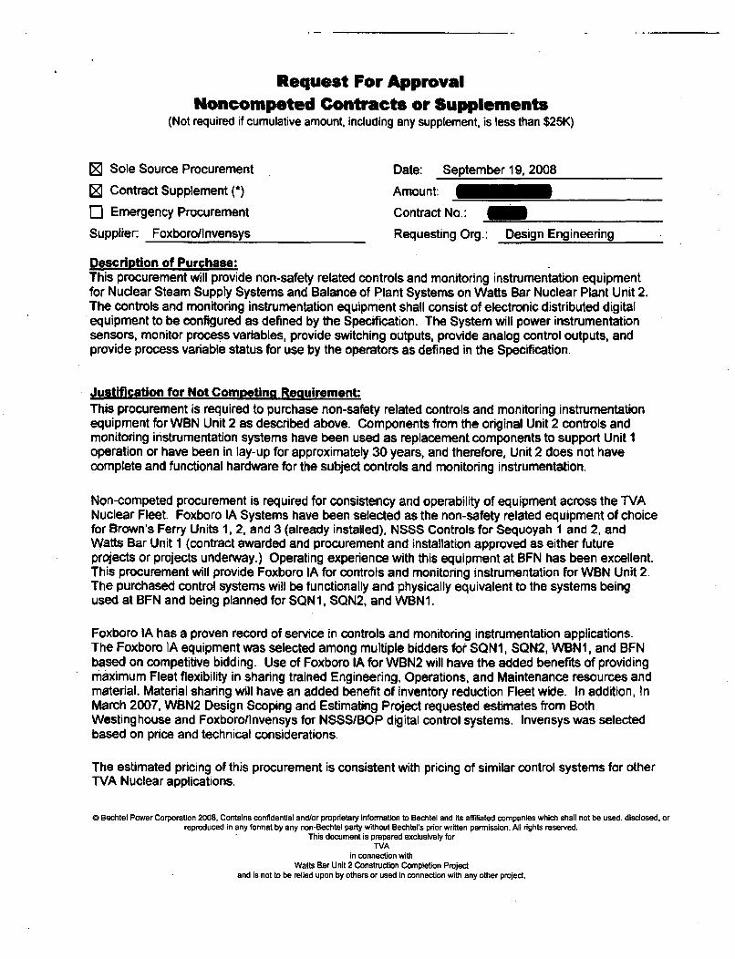
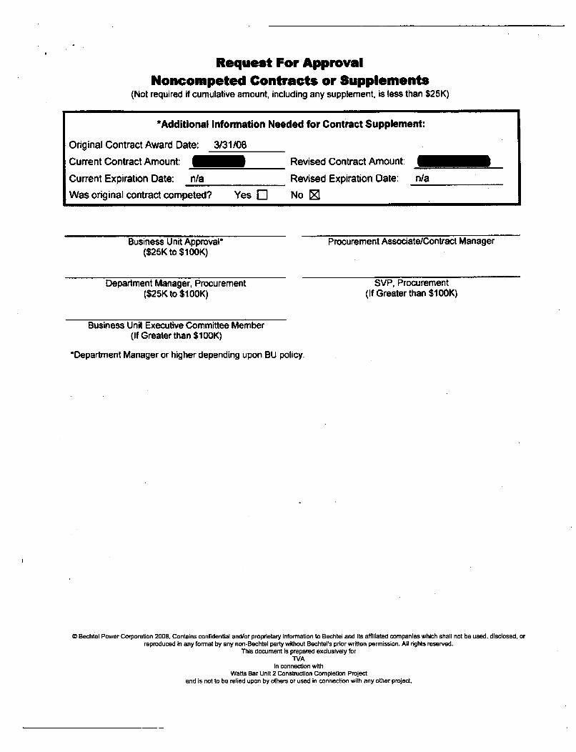
Request For ApprovalNoncompeted Contracts or Supplements
(Not required if cumulative amount, including any supplement, is less than $25K)
[ Sole Source Procurement Date: September 19, 2008
[ Contract Supplement (*) Amount:
5 Emergency Procurement Contract No.:
Supplier Foxboro/Invensys Requesting Org.: Design Engineering
Description of Purchase:This procurement will provide non-safety related controls and monitoring instrumentation equipmentfor Nuclear Steam Supply Systems and Balance of Plant Systems on Watts Bar Nuclear Plant Unit 2.The controls and monitoring instrumentation equipment shall consist of electronic distributed digitalequipment to be configured as defined by the Specification. The System will power instrumentationsensors, monitor process variables, provide switching outputs, provide analog control outputs, andprovide process variable status for use by the operators as defined in the Specification.
Justificaton for Not Comretina RecuirementThis procurement is required to purchase non-safety related controls and monitoring instrumentationequipment for WBN Unit 2 as described above. Components from the original Unit 2 controls andmonitoring instrumentation systems have been used as replacement components to support Unit Ioperation or have been in lay-up for approximately 30 years, and therefore, Unit 2 does not havecomplete and functional hardware for the subject controls and monitoring instrumentation.
Non-competed procurement is required for consistency and operability of equipment across the TVANuclear Fleet. Foxboro IA Systems have been selected as the non-safety related equipment of choicefor Brown's Ferry Units 1, 2, and 3 (already installed), NSSS Controls for Sequoyah I and 2, andWatts Bar Unit 1 (contract awarded and procurement and installation approved as either futureprojects or projects underway.) Operating experience with this equipment at BFN has been excellent.This procurement will provide Foxboro IA for controls and monitoring instrumentation for WBN Unit 2.The purchased control systems will be functionally and physically equivalent to the systems beingused at BFN and being planned for SQN1, SQN2, and WBNI.
Foxboro IA has a proven record of service in controls and monitoring instrumentation applications.The Foxboro IA equipment was selected among multiple bidders fot SQN1, SQN2, WBN1, and BFNbased on competitive bidding. Use of Foxboro IA for WBN2 will have the added benefits of providingmaximum Fleet flexibility in sharing trained Engineering, Operations, and Maintenance resources andmaterial. Material sharing will have an added benefit of inventory reduction Fleet wide. In addition, inMarch 2007, WBN2 Design Scoping and Estimating Project requested estimates from BothWestinghouse and Foxboro/Invensys for NSSS/BOP digital control systems. Invensys was selectedbased on price and technical considerations.
The estimated pricing of this procurement is consistent with pricing of similar control systems for otherTVA Nuclear applications.
© Bechtel Power Corporation 2008, Contains confidential and/or proprietary information to Bechtel and its affiliated companies which shall not be used. disclosed, orreproduced in any format by any non-Bechtel party without Bechtel's prior written permission. All rights reserved.
This document is prepared exclusively forTVA
in connection withWatts Bar Unit 2 Construction Completion Project
and is not to be relied upon by others or used in connection with any other project,
Request For ApprovalNoncompeted Contracts or Supplements
(Not required if cumulative amount, including any supplement, is less than $25K)
*Additional Information Needed for Contract Supplement:
Original Contract Award Date: 3131/08
Current Contract Amount: 1 Revised Contract Amount:
Current Expiration Date: n/a Revised Expiration Date: n/a
Was original contract competed? Yes E No 21
Business Unit Approval*($25K to $100K)
Procurement Associate/Contract Manager
SVP, Procurement(If Greater than $1100K)
Department Manager, Procurement($25K to $IOOK)
Business Unit Executive Committee Member(If Greater than $10OK)
*Department Manager or higher depending upon BU policy.
0 Bechtel Power Corporation 2008, Contains confidential and/or proprietary Information to Bechtel and its affiliated companies which shall not be used. disclosed, orreproduced in any format by any non-Bechtel party without Bechtel's prior written permission. All rights reserved.
This document is prepared exclusively forTVA
in connection withWatts Bar Unit 2 Construction Completion Project
and is not to be relied upon by others or used in connection with any other project,

Requisition Number: 25402-011-MRA-JD01-00001Revision: 000
Attachment 2
Section QR- 1.6-3 of PNQAMProject Nuclear Quality Assurance Manual
Rev. 2
a Bechtel Power Corpration 2008, Contains confidential and/or proprietary Inrfonaelon to Bechtel and its affiliated companies wich shall rot be used, disclosed, orreproduced in any format by any non-Bechtel party without Bechtel's prior written permission. All rights reserved.
This document is prepared exclusively forWA
in connection withWatts Bar Unit 2 Construction Completion Project
and is not to be relied upon by others or used in connection wilh any other project.
Watts Bar Unit 2 Construction Completion ProjectPROJECT NUCLEAR QUALITY ASSURANCE MANUAL
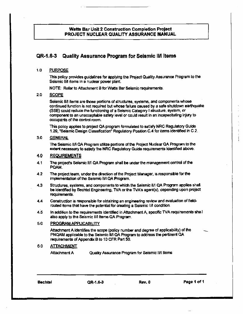
QR-1.6-3 Quality Assurance Program for Seismic Il/I Items
1.0 PURPOSEThis policy provides guidelines for applying the Project Quality Assurance Program to theSeismic Il/I items in a nuclear power plant.NOTE: Refer to Attachment B for Watts Bar Seismic requirements.
2.0 SCOPESeismic II! items are those portions of structures, systems, and components whosecontinued function is not required but whose failure caused by a safe shutdown earthquake(SSE) could reduce the functioning of a Seismic Category I structure, system, orcomponent to an unacceptable safety level or could result in an incapacitating injury tooccupants of the control room.This policy applies to project QA program formulated to satisfy NRC Regulatory Guide1.29, "Seismic Design Classification" Regulatory Positon C.4 for items identified in C.2.
3.0 GENERALThe Seismic Il/I QA Program utilize portions of the Project Nuclear QA Program to theextent necessary to satisfy the NRC Regulatory Guide requirements identified above.
4,Q REQUIREMENTG4.1 The projects Seismic 11/I QA Program shall be under the management control of the
POAM.
4.2 The project team, under the direction of the Project Manager, is responsible for theimplementation of the Seismic 111 QA Program.
4.3 Structures, systems, and components to which the Seismic I1/I QA Program applies shallbe identified by Bechtel Engineering, TVA or the TVA's agent(s), depending upon projectrequirements.
4.4 Construction is responsible for obtaining an engineering review and evaluation of field-routed items that have the potential for creating a Seismic Il/I condition.
4.5 In addition to the requirements Identified in Attachment A, specific TVA requirements shallalso apply to the Seismic II/I Items QA Program.
5.0 PROGRAM APPLICABILITYAttachment A identifies the scope (policy number and degree of applicability) of thePNQAM applicable to the Seismic 111 QA Program to address the pertinent QArequirements of Appendix B to 10 CFR Part 50.
6.0 A'TACHMENTAttachment A Quality Assurance Program for Seismic I/I1 Items
Bechtel OR-1.6-3 Rev. 0 Page I of 1
Watts Bar Unit 2 Construction Completion ProjectPROJECT NUCLEAR QUALITY ASSURANCE MANUAL
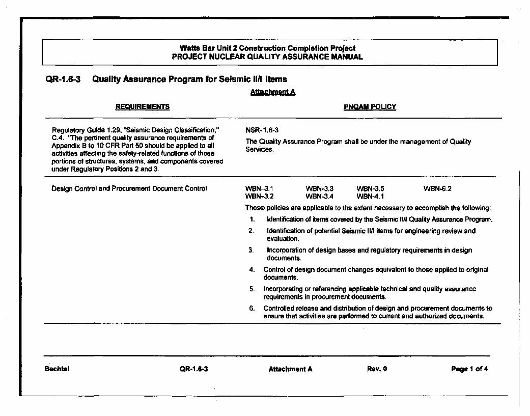
QR-1.6-3 Quality Assurance Program for Seismic Il/I ItemsAttachmt A
REQUIREMENTS PNQAM POLICY
Regulatory Guide 1.29, "Seismic Design Classification," NSR-1.6-3C.4. 'The pertinent quality assurance requirements of The Quality Assurance Program shall be under the management of QualityAppendix B to 10 CFR Part 50 should be applied to allactivities affecting the safety-related functions of thoseportions of structures, systems, and components coveredunder Regulatory Positions 2 and 3.
Design Control and Procurement Document Control WBN-3.1 WBN-3.3 WBN-3.5 WBN-6.2
WBN-3.2 WBN-3.4 WBN-4.1
These policies are applicable to the extent necessary to accomplish the following:1. Identification of items covered by the Seismic li1t Quality Assurance Program.2. Identification of potential Seismic II/I items for engineering review and
evaluation.3. Incorporation of design bases and regulatory requirements in design
documents.
4. Control of design document changes equivalent to those applied to originaldocuments.
5. Incorporating or referencing applicable technical and quality assurancerequirements in procurement documents.
6. Controlled release and distribution of design and procurement documents toensure that activities are performed to current and authorized documents.
Bechtel QR-1.6-3 Attachment A Rev. 0 Page I of 4
Watts Bar Unit 2 Construction Completion ProjectPROJECT NUCLEAR QUALITY ASSURANCE MANUAL
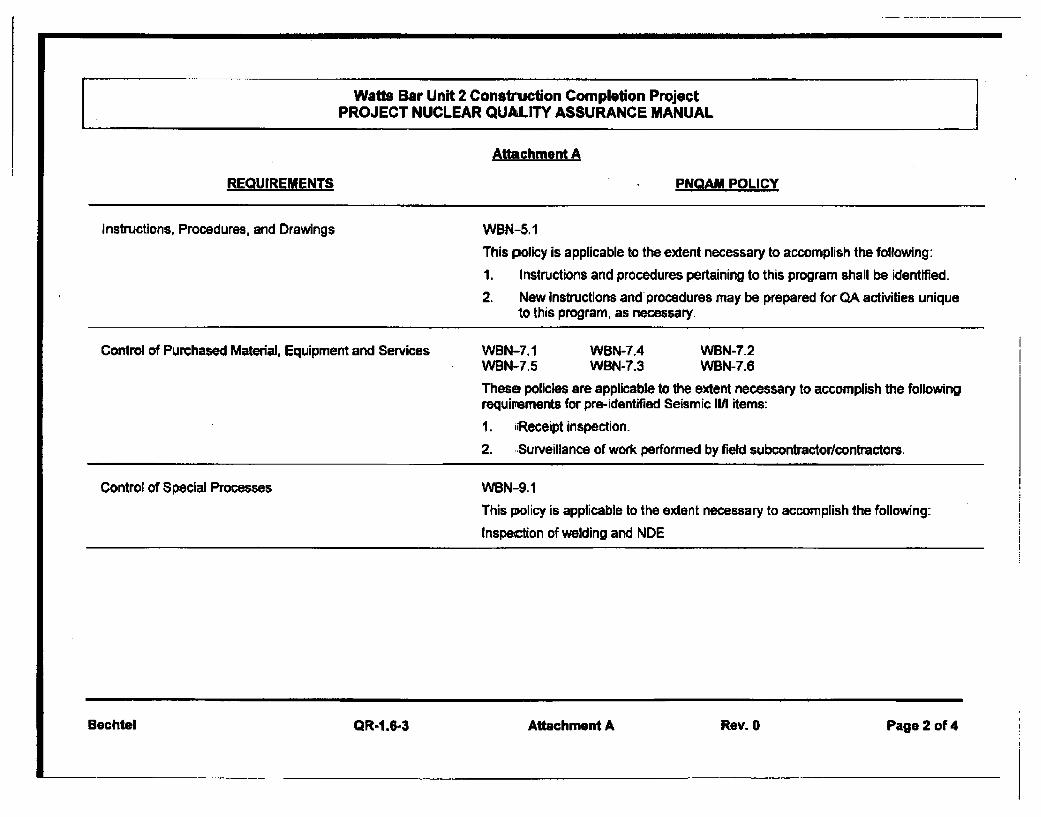
Attachment A
REQUIREMENTS PNQAM POLICY
Instructions, Procedures, and Drawings WBN-5.1
This policy is applicable to the extent necessary to accomplish the following:
1. Instructions and procedures pertaining to this program shall be identified.2. New instructions and procedures may be prepared for QA activities unique
to this program, as necessary.
Control of Purchased Material, Equipment and Services WBN-7.1 WBN-7.4 WBN-7.2WBN-7.5 WBN-7.3 WBN-7.6These policies are applicable to the extent necessary to accomplish the followingrequirements for pro-identified Seismic III items:
1. iiReceipt inspection.2. .Surveillance of work performed by field subcontractor/contractors.
Control of Special Processes WBN-9.1
This policy is applicable to the extent necessary to accomplish the following:
Inspection of welding and NDE
Bechtel QR-1.6-3 Attachment A Rev. 0 Page 2 of 4
Watts Bar Unit 2 Constmrction Completion ProjectPROJECT NUCLEAR QUALITY ASSURANCE MANUAL
Attachment A
REQUIREMENTS PNQAM POLICY
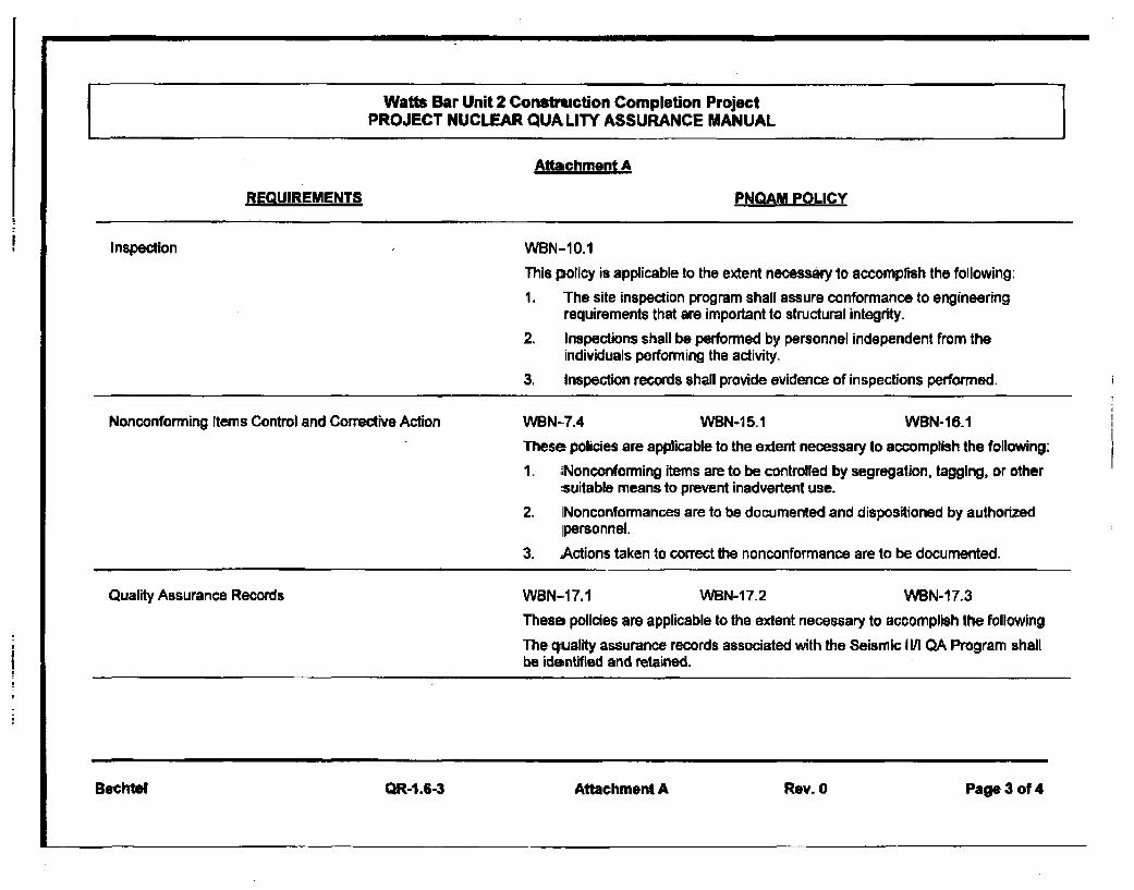
Inspection WBN-1O.1
This policy is applicable to the extent necessary to accomplish the following:
1, The site inspection program shall assure conformance to engineeringrequirements that are important to structural integrity.
2. Inspections shall be performed by personnel independent from theindividuals performing the activity.
3. Inspection records shall provide evidence of inspections performed.
Nonconforming Items Control and Corrective Action WBN-7.4 WBN-15.1 WBN-16.1These policies are applicable to the extent necessary to accomplish the following:
1. dNonconforming items are to be controfled by segregation, tagging, or other:suitable means to prevent inadvertent use.
2. INonconformances are to be documented and dispositioned by authorizedpersonnel.
3. Actions taken to correct the nonconformance are to be documented.
Quality Assurance Records WBN-1 7.1 WBN-17.2 WBN-17.3
These policies are applicable to the extent necessary to accomplish the followingThe quality assurance records associated with the Seismic 11/1 QA Program shallbe identified and retained.
Bechtel QR-1.6-3 Attachment A Rev. 0 Page 3 of 4
Watts Bar Unit 2 Construction Completion ProjectPROJECT NUCLEAR QUAJLITY ASSURANCE MANUAL
Attachment A
REQUIREMENTS PNQAM POLICY
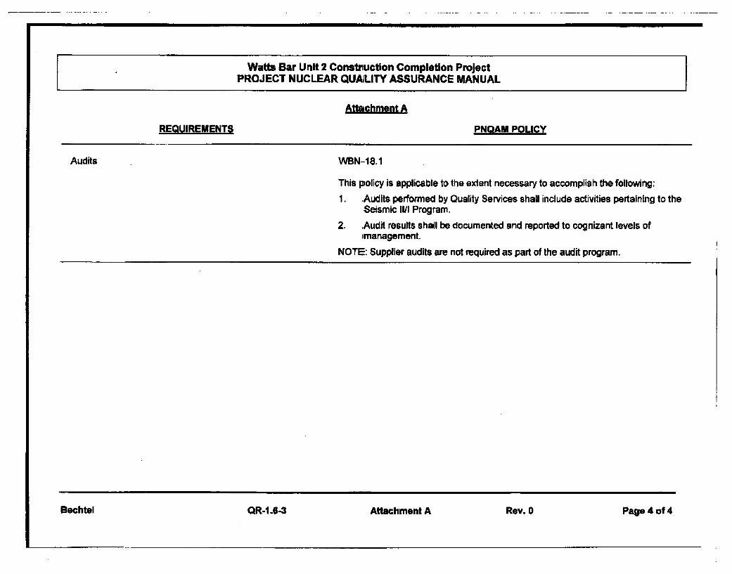
Audits WBN-18.1
This policy is applicable to the extent necessary to accomplish the following:1. Audits performed by Quality Services shall include activities pertaining to the
Seismic II/I Program.2. Audit results shall be documented and reported to cognizant levels of
'managementNOTE: Supplier audits are not required as part of the audit program.
Bechtel QR-1.6-3 Attachment A Rev. 0 Page 4 of 4

Requisition Number: 25402-011-MRA-JD01-00001Revision: 000
Attachment 3
Quality Surveillance Plan
0 Bechtel Power Corporation 2008. Contains convIldential andfor propretary information to Bechtel and its affiliated companies which shaD not be used, disclosed, or
reproduced in any format by any non-Bechtel party without Bechtel's pnor written permission. All rights reserved.
This document is prepared eXClUSively for
TVAin connection with
Watts Bar Unit 2 Constmruton Completion Projectand is not to be relied upon by others or used in connection withl any other proiect.
I
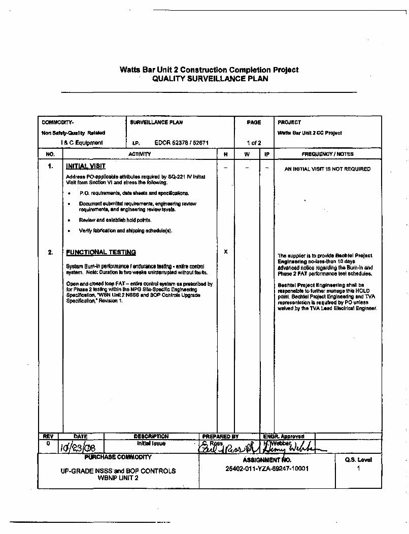
Watts Bar Unit 2 Construction Compleoion ProjectQUALITY SURVEILLANCE PLAN
COMMODITY- SURVEILLANCE PLAN PAGE PROJECT
Non Sfety-Quetlty Related Watts Bar Unft 2 CC Project
I & C Equipment I.P. EDCR 62378152671 1 of 2
NO, ACTIVITY H W IP FREQUENCYINOTES
1. INITIAL VISIT- AN IN)TIAL VISIT IS NOT REQUIRED
Address PO-applicable attributes required by S-221 IV InitialVisit form Section VI and stress the following:
* P.O. requirements, data steets and specilicatlona.
* Document submittal requirements, engineering reviewrequirements, and engineering review levels.
* Review and establish hold points.
" Verify fabricatlon and shipping schedule(s).
2. FUNCTIONAL TESTING X rhe supplier Is to provide Bechtel Project
Engineering no-lees-than 10 daysSystem BumIn performance I endurance tdftii indre wntral adwlvned notia regardlin the Burn-in andsystem. Note: Ouration Is two weeks uninterrupted without fauits, Phase 2 FAT performance tesi schedules.
Open and closed loop FAT- entire control system as prescribed by Bechtel ProJect Engineering shall befor Phase 2 testing within the MPG Slta-Specific Engineering responsible to further manage this HOLDSpaclflctiork 'WBN Unit 2 NSSS and SOP Conirols Upgrade point. Bechtel Project Engineering end TVASpecificatlort' Revision 1. representation Is required by PO unlaess
waived by the TVA Lead Electrical Engineer.
REV IDATE DESCRIPTION PREPARED BY ENGR. Approved
0 Initial lastsu R.Webbe,
PURCHASE COMMODITY ASSIGNMENT K.S. Leve
UP-GRADE NSSS and BOP CONTROLS 21402-0l1-YZA-9247-10001WBNP UNIT 2
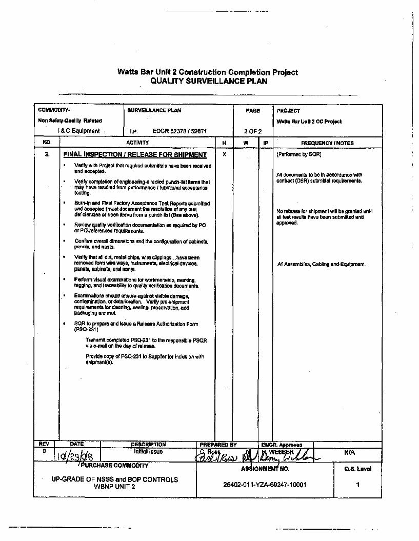
Watts Bar Unit 2 Construction Completion ProjectQUALITY SURVEILLANCE PLAN
COMMODITY- SURVEILLANCE PLAN PAGE PROJECT
Non Safety.QualIly IRelsad Watts Bar Unit 2 CC Project
I & C Equipment I.P. EDCR 52378 / 52671 2 OF 2
NO, ACTIVITY H W IP FREQUENCY I NOTES
3. FINAL INSPECTION I RELEASE FOR SHIPMENT x (Peoned by SOR)
Verify with Projeol that required submittals have been receivedand ac~epted. All documents to be In accordance withSVeadly completion of englneering-dlreeted punch-tsl Items that contract (DSR) submittal requirements.may have resulted from pearormmnoe i funotworal acceptancetesting.
Burnin and Final Factory Acceptance Test Reports submittedand accepted (must document the resolution of any test No release far shipment will be granted untildeflcienclas or open items from a punch-list (See above), all test results have been submitted and
Review quality verlitcation dowmmentaffon as required by PO approved.
or PO-referenced requirements.
Conirm overall dimensions and the conltpuution of cabinets,panels., and nests.
* Vedfy that all dir, metal chips, wire cllpplngs...have beenremoved form wire ways, instruments, electrical devices, Aft Assemblies, Cabling ard Equipment.panels, cabinets, and nsts.
* Perform visual examinations for workmanhlip. masking.tagging, and traceability to qualty verificalion documents
* Examinations should ensure against visible damage,contamination, ordeterioration. Veriy pre-shlpmentrequirements for cleaing, sealing, preservation, andpackaging are met,
SOR to prepare and Issue a Release Authorization Form(PS-231)
Transmit completed PS0-231 to tte responsible PSQRvis e-mail on the day of release.
Provide copy of PS-231 to Supplier for Inclusion withshipment(s).
REV DATE DESCRIPTION PREPARED BY EiNGR. Approved
uSaInitial Issue a2P I/PURCHASE COMMODITY NMENd %5. ,
UP-GRADE OF N$S$ and BOP CONTROLS 26402-011-YZA49247-10001WBNP UNIT 2 2
Watts Bar Unit 2 Construction Completion ProjectQUALITY SURVEILLANCE PLAN
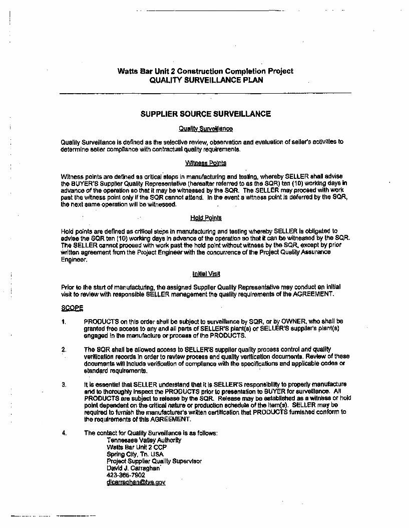
SUPPLIER SOURCE SURVEILLANCE
Quality Surveillance
Quality Surveillance is defined as the selective review, observation and evaluation of seller's activities todetermine seller compliance with contractual quality requirements,
Witness Points
Witness polnts are defined as critical steps in manufacturing and testing, whereby SELLER shall advisethe-BUYER'S Supplier Quality Representative (hereafter referred to as the SQR) ten (10) working days inadvance of the operation so that it may be witnessed by the SR. The SELLER may proceed with workpast the witness point only if the SR cannot attend. In the event a witness point Is deferred by the SCR,the next same operation will be witnessed,
Hold Points
Hold points are defined as critical steps in manufacturing and tesUng whereby SELLER Is obligated toadvise the S8R ten (10) working days in advance of the operation so that it can be witnessed by the SR.The SELLER cannot proceed with work past the hold point without witness by the SQR. except by priorWritten agreement from the Project Engineer with the concurrence of the Project Quality AssuranceEngineer.
Initial Visit
Prior to the start of manufacturing, the assigned Supplier Quality Representative may conduct an initialvisit to review with responsible SELLER management the quality requirements of the AGREEMENT,
I. PRODUCTS on this order shall be subject to surveillance by SQR, or by OWNER, who shall begranted free access to any and all parts of SELLER'S plant(s) or SELLER'S suppliers plant(s)engaged In the manufacture or process of the PRODUCTS.
2. The 8QR shall be allowed access to SELLER'8 supplier quality process control and qualityverification records In order to review process and quality verification documents. Review of thesedocuments will Include verification of compliance with the specifications and applicable codes orstandard requirements.
3. It is essential that SELLER understand that It Is SELLER'S responsibility to properly manufactureand to thoroughly Inspect the PRODUCTS prior to presentation to BUYER for surveillance. AllPRODUCTS are subject to release by the SCR. Release may be established as a witnbss or holdpoint dependent on the critical nature or production schedule of the item(s). SELLER may berequired to furnish the manufacturer's written certification that PRODUCTS furnished conform tothe requirements of this AGREEMENT.
4. The contact for Quality Surveillance is as follows:Tennessee Valley AuthorityWatts Bar Unit 2 CCPSpring City, Tn. USAProject Supplier Quality SupervisorDavid J. Carraghan"423-366-7902dlcarraahenftvapov
Watts Bar Unit 2 Construction Completion ProjectQUALITY SURVEILLANCE PLAN
5. it is understood that the PURCHASE ORDER prices include these surveillance requirements. No
request for extra cost on account of surveillance requirements will be entertained.
6. Source Surveillance Plan descriptions:
H Hold PointW = Witness PointIP In Process
SPECIFIC QUALITY SURVEILLANCE
The PRODUCTS covered by the PURCHASE ORDER will be subject to the level or QualitySurveillance activity as defined In the attached Surveillance Plan, or other technical requirements.Witness and Hold Points are as defined in the Surveillance Plan and/or Technical Speclfical:Ions...

Requisition Number: 25402-011 -MRA-JD01 -00001Revision: 000
Attachment 4
TVA specification, "WBN Unit 2 NSSS and BOP Controls Upgrade Specification",Revision I
a Bechtel Power Corporation 2008. Contains coanlidential anrd/or proprietary information to Bechtel and its affiliated companies which shan not be used, disclosed, orreproduced in any format by any non-Bechtel party vAthout Bechtel's prior written permission. All rights reserved.
This document is prepared exclusively forWVA
in connection withWatts Bar Unit 2 Construction Completion Project
and is not to be relied upon by others or used in connection with any other project.
q U
TITLEWBN Unit 2 NSSS and BOP Controls
Upgrade Specification
SpecificationRev. 0001Page 1 of440
NPG Site-SpecificEngineeringSpecification
Effective Date s o/7-/ yL _______________________________________________________________________________________________
Prepared by: Henry Webber ((Reviewed by: '
Dan Faulkner Date
Approved by: 4Ck.:: a,1dB,Steve Hilmes .. ate
i
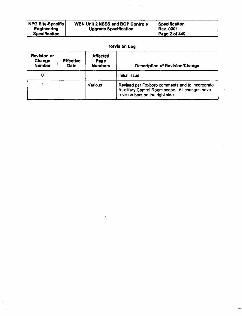
NPG Site-Specific W1N Unit 2 NSSS and BOP Controls SpecificationEngineering Upgrade Specification Rev. 0001Specification Page 2 of 440
Revision Log
Revision or AffectedChange Effective PageNumber Date Numbers Description of RevisionlChange
0 Initial issue
1 Various Revised per Foxboro comments and to incorporateAuxilliary Control Room scope. All changes haverevision bars on the right side.
NPG Site-Specific WBN Unit 2 NSSS and BOP Controls SpecificationEngineering Upgrade Specification Rev. 0001Specification Page 3 of 440
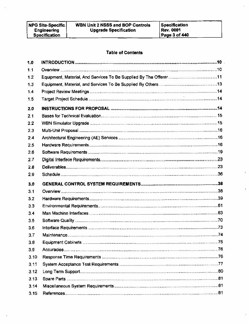
Table of Contents
1.0 INTRODUCTION .................................................................................................................... 10
1 .1 O v e rv ie w ....... ........................................................................................................................ 1 0
1.2 Equipment, Material, And Services To Be Supplied By The Offerer ................................... 11
1.3 Equipment, Material, and Services To Be Supplied By Others ........................................... 13
1.4 Project Review Meetings ................................................................................................... 14
1.5 Target Project Schedule .............................................. 14
2.0 INSTRUCTIONS FOR PROPOSAL .................................................................................. 14
2.1 Bases for Technical Evaluation .......................................................................................... 15
2.2 W BN Simulator Upgrade ................................................................................................... 15
2.3 Multi-Unit Proposal .................................................. 16
2.4 Architectural Engineering (AE) Services ............................................................................ 16
2.5 Hardware Requirements ................................................................................................... 16
2.6 Software Requirements ..................................................................................................... 19_.7 _Digita Interface Requirem ents ..__....., ....... . .......................... 2....... 3
2.8 Deliverables ........................................................................................................................... 23
2 .9 S c h e d u le ................................................................................................................................ 3 6
3.0 GENERAL CONTROL SYSTEM REQUIREMENTS ........................................................... 38
3.1 Overview ................................................................................................................................ 38
3.2 Hardware Requirements ................................................................................................... 39
3.3 Environmental Requirements ............................................................................................. 61
3.4 M an Machine Interfaces ................................................................................................... 63
3.5 Software Q uality ..................................................................................................................... 70
3.6 Interface Requirem ents ........................................................................................................ 73
3.7 Maintenance .......................................................................................................................... 74
3.8 Equipment Cabinets ............................................................................................................... 75
3.9 Accuracies .............................................................................................................................. 76
3.10 Response Tim e Requirements .......................................................................................... 76
3.11 System Acceptance Test Requirem ents ............................................................................ 77
3.12 Long Term Support ................................................................................................................. 80
3.13 Spare Parts ............................................................................................................................ 81
3.14 M iscellaneous System Requirements ............................................................................... 81
3.15 References ............................................................................................................................. 81
NPG Site-Specific WBN Unit 2 NSSS and SOP Controls SpecificationEngineering Upgrade Specification Rev. 0001Specification Page 4 of 440
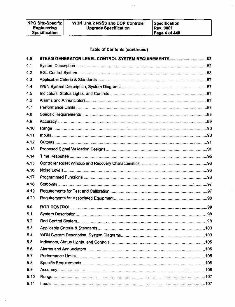
Table of Contents (continued)
4.0 STEAM GENERATOR LEVEL CONTROL SYSTEM REQUIREMENTS ........................... 82
4.1 System Description ................................................................................................................. 82
4.2 SGL Control System ...................................... . ............................................... 83
4.3 Applicable Criteria & Standards ........................................................................................ 87
4.4 W BN System Description, System Diagrams .................................................................... 87
4.5 Indicators, Status Lights. and Controls .............................................................................. 87
4.6 Alarms and Annunciators ................................................................................................... 87
4.7 Performance Lim its ................................................................................................................ 88
4.8 Specific Requirem ents ...................................................................................................... 88
4.9 Accuracy ................................................................................................................................. 89
4 .10 R a n g e .......................................................................................................... .......................... g0
4 .1 1 In p u ts ..................................................................................................................................... 9 0
4.12 Outputs................................................................................................................................. 91
4.13 Proposed Signal Validation Designs ................................................................................. 91
4.14 Time Response ................................................................................................................. 95
4.15 Controller Reset W indup and Recovery Characteristics .................................................... 96
4.16 Noise Levels .......................................................................................................................... 96
4.17 Programmed Functions ..................................................................................................... 96
4.18 Setpoints ................................................................................................................................ 97
4.19 Requirements for Test and Calibration .............................................................................. 97
4.20 Requirements for Associated Equipment .......................................................................... 98
5.0 ROD CO NTROL ..................................................................................................................... 98
5.1 System Description ................................................................................................................. 98
5.2 Rod Control System................................................................................................................ 98
5.3 Applicable Criteria & Standards ............................................................................................ 103
5.4 W BN System Description, System Diagrams ........................................................................ 103
5.5 Indicators, Status Lights. and Controls ................................................................................. 105
5.6 Alarms and Annunciators ..................................................................................................... 105
5.7 Perform ance Lim its ............................................................................................................... 105
5.8 Specific Requirem ents ......................................................................................................... 106
5 .9 A c c u ra cy .............................................................................................................................. 10 6
5 .1 0 R a n g e ................................................................................................................................... 1 0 7
5 .1 1 In p u ts ................................................................................................................................... 1 0 7
NPG Site-Specific WBN Unit 2 NSSS and BOP Controls SpecificationEngineering Upgrade Specification Rev. 0001Specification Page 5 of 440
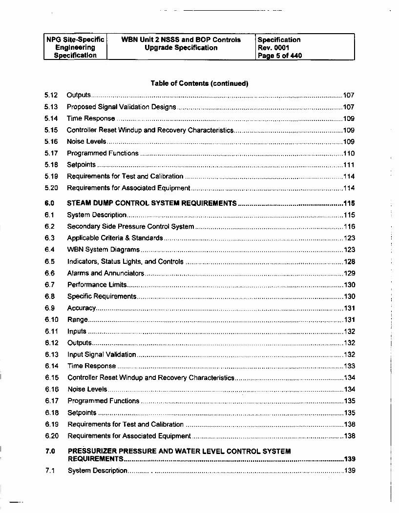
Table of Contents (continued)
5.12 Outputs ................................................................................................................................. 107
5.13 Proposed Signal Validation Designs ..................................................................................... 107
5.14 Tim e Response .................................................................................................................... 109
5.15 Controller Reset W indup and Recovery Characteristics ........................................................ 109
5.16 Noise Levels ......................................................................................................................... 109
5.17 Programmed Functions ........................................................................................................ 110
5.18 Setpoints .............................................................................................................................. 111
5.19 Requirem ents for Test and Calibration ................................................................................. 114
5.20 Requirem ents for Associated Equipm ent .............................................................................. 114
6.0 STEAM DUMP CONTROL SYSTEM REQUIREMENTS ................................................. 115
6.1 System Description .............................................................................................................. 115
6.2 Secondary Side Pressure Control System ............................................................................ 116
6.3 Applicable Criteria & Standards ............................................................................................ 123
6.4 W BN System Diagrams ........................................................................................................ 123
6.5 Indicators, Status Lights, and Controls ................................................................................. 128
6.6 Alarm s and Annunciators ...................................................................................................... 129
6.7 Perform ance Lim its ............................................................................................................... 130
6.8 Specific Requirem ents ......................................................................................................... 130
6.9 Accuracy ............................................................................................................................... 131
6 .10 R a n g e ................................................................................................................................... 13 1
6 .1 1 In p u ts ........................................... ....................................................................................... 1 3 2
6 .1 2 O u tp u ts ................................................................................................................................. 13 2
6.13 Input Signal Validation .......................................................................................................... 132
6.14 Time Response ................................................................................................................... 133
6.15 Controller Reset W indup and Recovery Characteristics ....................................................... 134
6.16 Noise Levels ......................................................................................................................... 134
6.17 Program med Functions ........................................................................................................ 135
6.18 Setpoints .............................................................................................................................. 135
6.19 Requirements for Test and Calibration ................................................................................. 138
6.20 Requirements for Associated Equipment .............................................................................. 138
7.0 PRESSURIZER PRESSURE AND WATER LEVEL CONTROL SYSTEM
REQ UIREMENTS ................................................................................................................. 139
7.1 System Description ............................................................................................................... 139
NPG Site-Specific WBN Unit 2 NSSS and BOP Controls SpecificationEngineering Upgrade Specification Rev. 0001Specification Page 6 of 440
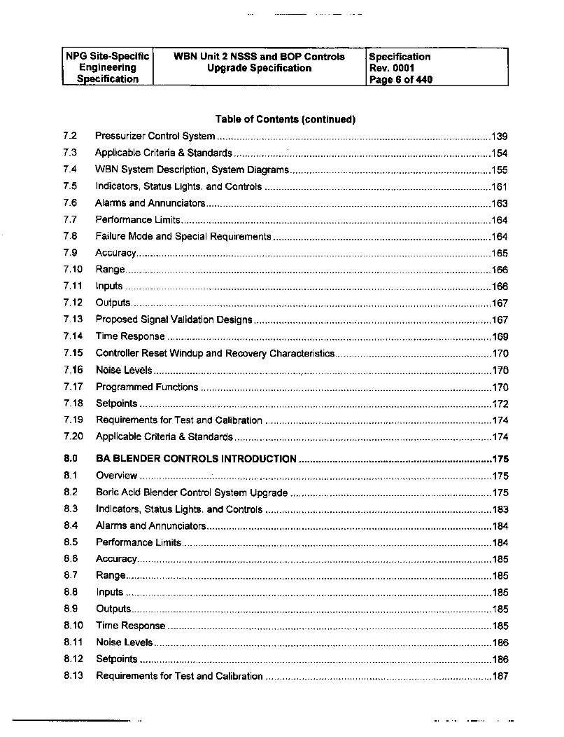
Table of Contents (continued)
7.2 Pressurizer Control System .................................................................................................. 139
7.3 Applicable Criteria & Standards ........................................................................................... 154
7.4 W BN System Description, System Diagrams ........................................................................ 155
7.5 Indicators, Status Lights. and Controls ................................................................................. 161
7.6 Alarms and Annunciators ...................................................................................................... 163
7.7 Performance Limits ............................................................................................................... 164
7.8 Failure Mode and Special Requirements .............................................................................. 164
7 .9 A c c u ra cy ............................................................................................................................... 1 6 57 .10 R a n g e ................................................................................................................................... 1 6 6
7 .1 1 In p u ts ................................................................................................................................... 1 6 6
7 .1 2 O utp uts ................................................................................................................................. 1 6 7
7.13 Proposed Signal Validation Designs ..................................................................................... 167
7.14 Time Response ................................................................................................................... 169
7.15 Controller Reset W indup and Recovery Characteristics........................................................ 170
7.16 Noise Levels .......................................................................................................................... 170
7.17 Programmed Functions ........................................................................................................ 170
7 .18 S e tp o ints .............................................................................................................................. 17 27.19 Requirements for Test and Calibration ................................................................................. 174
7.20 Applicable Criteria & Standards ............................................................................................ 174
8.0 BA BLENDER CONTROLS INTRODUCTION ..................................................................... 175
8 .1 O ve rv ie w ................................. ............................................................................................. 1 75
8.2 Boric Acid Blender Control System Upgrade ........................................................................ 175
8.3 Indicators, Status Lights. and Controls ................................................................................. 183
8.4 Alarms and Annunciators ...................................................................................................... 184
8.5 Performance Limits ............................................................................................................... 184
8 .6 A cc u ra c y ............................................................................................................................... 18 5
8 .7 R a n g e ................................................................................................................................... 18 5
8 .8 In p u ts ................................................................................. ................................................. 1 8 5
8 .9 O u tp u ts ................................................................................................................................. 18 5
8.10 Time Response .................................................................................................................... 185
8.11 Noise Levels ......................................................................................................................... 186
8.12 Setpoints ................................................................... ......... ................... 186
8.13 Requirements for Test and Calibration ................................................................................. 187
NPG Site-Specific WBN Unit 2 NSSS and BOP Controls SpecificationEngineering Upgrade Specification Rev. 0001Specification Page 7 of 440
Table of Contents (continued)
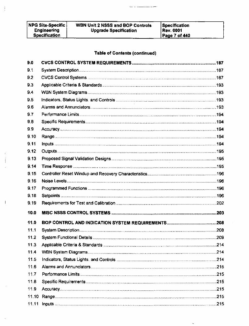
9.0 CVCS CONTRO L SYSTEM REQUIREMENTS .................................................................... 187
9.1 System Description ............................................................................................................... 187
9.2 CVCS Control System s ........................................................................................................ 187
9.3 Applicable Criteria & Standards ............................................................................................ 193
9.4 W BN System Diagrams ........................................................................................................ 193
9.5 Indicators, Status Lights. and Controls ................................................................................. 193
9.6 Alarms and Annunciators ..................................................................................................... 193
9.7 Perform ance Limits ............................................................................................................... 194
9.8 Specific Requirements .......................................................................................................... 194
9.9 Accuracy ............................................................................................................................... 194
9 .10 R a n g e ................................................................................................................................... 1 9 4
9.11 Inputs ................................................................................................................................... 194
9.12 Outputs ................................................................................................................................. 195
9.13 Proposed Signal Validation Designs ..................................................................................... 195
9.14 Tim e Response .................................................................................................................... 195
9.15 Controller Reset W indup and Recovery Characteristics ........................................................ 196
9.16 Noise Levels ......................................................................................................................... 196
9.17 Program med Functions ........................................................................................................ 196
9.18 Setpoints .............................................................................................................................. 196
9.19 Requirements for Test and Calibration ................................................................................. 202
10.0 M ISC NSSS CONTRO L SYSTEMS ..................................................................................... 203
11.0 BOP CONTROL AND INDICATION SYSTEM REQUIREMENTS ........................................ 208
11.1 System Description ............................................................................................................... 208
11.2 System Functional Details .................................................................................................... 209
11.3 Applicable Criteria & Standards............................................................................................ 214
11.4 W BN System Diagram s ...................................................................................................... 214
11.5 Indicators, Status Lights. and Controls ................................................................................. 214
11.6 Alarms and Annunciators ...................................................................................................... 215
11.7 Performance Lim its ............................................................................................................... 215
11.8 Specific Requirements .......................................................................................................... 215
11.9 Accuracy ............................................................................................................................... 215
1 1 .10 R a n g e ............................ ...................................................................................................... 2 1 5
1 1 .1 1 In p u ts ........ ........................................................................................................................... 2 1 5
NPG Site-Specific WBN Unit 2 NSSS and BOP Controls SpecificationEngineering Upgrade Specification Rev. 0001Specification Page 8 of 440
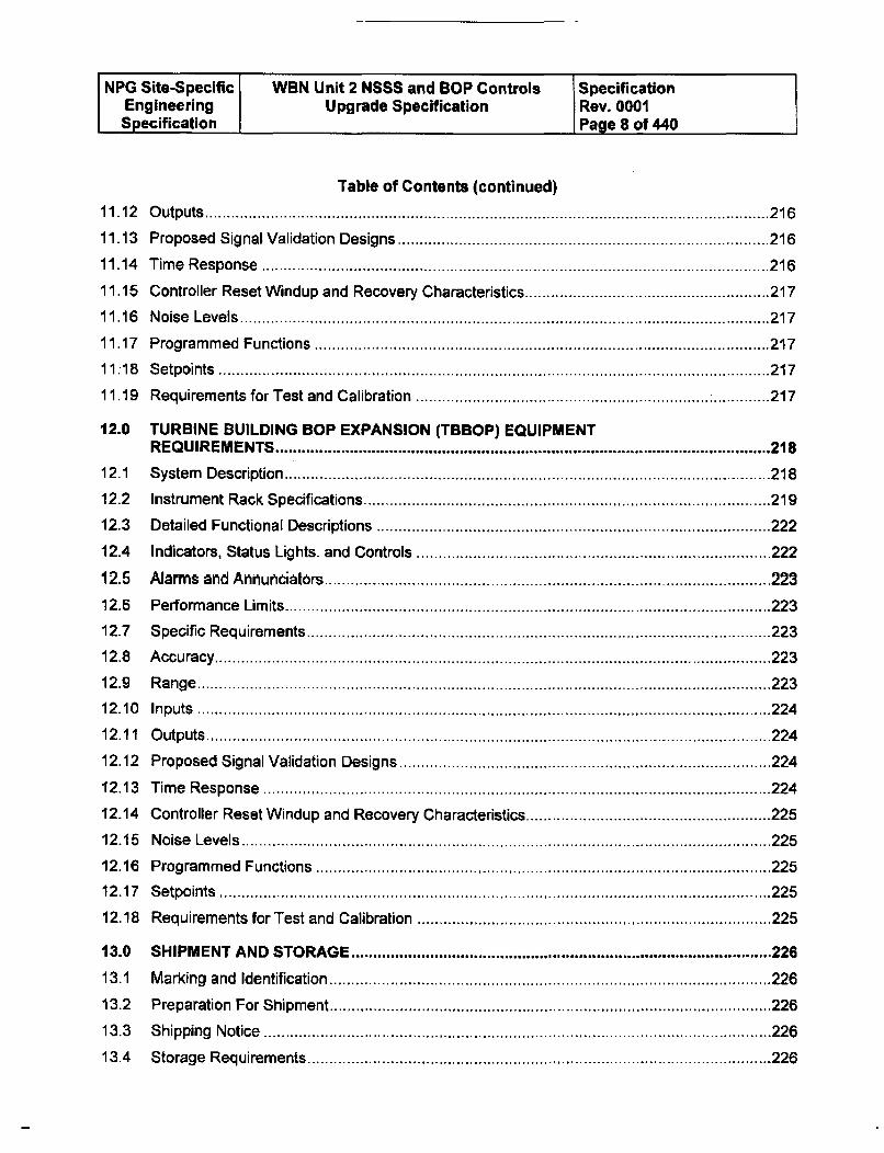
Table of Contents (continued)
1 1 .12 O u tp uts ................................................................................................................................. 2 1 611.13 Proposed Signal Validation Designs ..................................................................................... 216
11.14 Time Response ................................................................................................................... 216
11.15 Controller Reset W indup and Recovery Characteristics ........................................................ 217
11.16 Noise Levels ......................................................................................................................... 217
11.17 Program med Functions ........................................................................................................ 217
1 1 .18 S e tp o ints ......................................... .................................................................................... 2 1 7
11.19 Requirem ents for Test and Calibration ................................................................... ............. 217
12.0 TURBINE BUILDING BOP EXPANSION (TBBOP) EQUIPMENTREQUIREMENTS ................................................................................................................. 218
12.1 System Description ............................................................................................... ............ 218
12.2 Instrument Rack Specifications ............................................................................................ 219
12.3 Detailed Functional Descriptions .......................................................................................... 222
12.4 Indicators, Status Lights. and Controls ................................................................................. 222
12.5 Alarms and Annurtidators...................................................................................................... 223
12.6 Perform ance Lim its ............................................................................................................... 223
12.7 Specific Requirements .......................................................................................................... 223
12.8 Accuracy ............................................................................................................................... 223
12 .9 R a n g e ............................................ ...................................................................................... 2 2 3
1 2 .10 In p u ts ................................................................................................................................... 2 2 4
12 .1 1 O utp uts ................................................................................................................................. 2 2 4
12.12 Proposed Signal Validation Designs ..................................................................................... 224
12.13 Time Response .................................................................................................................... 224
12.14 Controller Reset W indup and Recovery Characteristics ........................................................ 225
12.15 Noise Levels ......................................................................................................................... 225
12.16 Program med Functions ........................................................................................................ 22512.17 Setpoints .............................................................................................................................. 225
12.18 Requirements for Test and Calibration ................................................................................. 225
13.0 SHIPM ENT AND STORAGE ................................................................................................ 226
13.1 Marking and Identification ..................................................................................................... 226
13.2 Preparation For Shipment .................................................................................................... 226
13.3 Shipping Notice .................................................................................................................... 226
13.4 Storage Requirements .......................................................................................................... 226
NPG Site-Specific WBN Unit 2 NSSS and BOP Controls SpecificationEngineering Upgrade Specification Rev. 0001Specification I Page 9 of 440
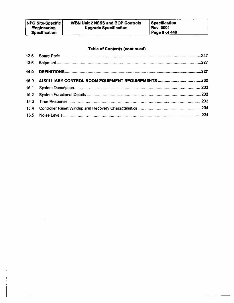
Table of Contents (continued)
13.5 Spare Parts .......................................................................................................................... 227
13.6 Shipment .............................................................................................................................. 227
14.0 DEFINITIO NS ....................................................................................................................... 227
15.0 AUXILLIARY CONTROL ROOM EQUIPMENT REQUIREMENTS ...................................... 232
15.1 System Description ............................................................................................................... 232
15.2 System Functional Details .................................................................................................... 232
15.3 Time Response .................................................................................................................... 233
15.4 Controller Reset W indup and Recovery Characteristics ........................................................ 234
15.5 Noise Levels ......................................................................................................................... 234
NPG Site-Specific WBN Unit 2 NSSS and BOP Controls SpecificationEngineering Upgrade Specification Rev. 0001Specification Page 10 of 440
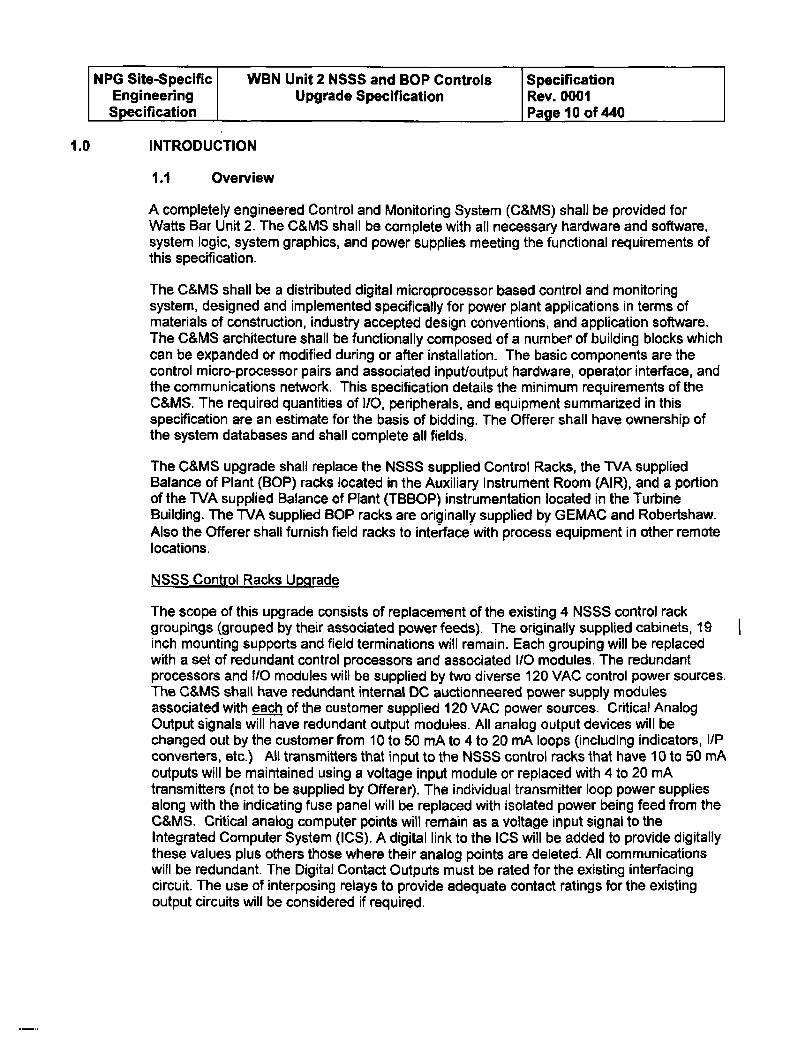
1.0 INTRODUCTION
1.1 Overview
A completely engineered Control and Monitoring System (C&MS) shall be provided forWatts Bar Unit 2. The C&MS shall be complete with all necessary hardware and software,system logic, system graphics, and power supplies meeting the functional requirements ofthis specification.
The C&MS shall be a distributed digital microprocessor based control and monitoringsystem, designed and implemented specifically for power plant applications in terms ofmaterials of construction, industry accepted design conventions, and application software.The C&MS architecture shall be functionally composed of a number of building blocks whichcan be expanded or modified during or after installation. The basic components are thecontrol micro-processor pairs and associated input/output hardware, operator interface, andthe communications network. This specification details the minimum requirements of theC&MS. The required quantities of I/O, peripherals, and equipment summarized in thisspecification are an estimate for the basis of bidding. The Offerer shall have ownership ofthe system databases and shall complete all fields.
The C&MS upgrade shall replace the NSSS supplied Control Racks, the TVA suppliedBalance of Plant (BOP) racks located in the Auxiliary Instrument Room (AIR), and a portionof the TVA supplied Balance of Plant (TBBOP) instrumentation located in the TurbineBuilding. The TVA supplied BOP racks are originally supplied by GEMAC and Robertshaw.Also the Offerer shall furnish field racks to interface with process equipment in other remotelocations.
NSSS Control Racks Upgrade
The scope of this upgrade consists of replacement of the existing 4 NSSS control rackgroupings (grouped by their associated power feeds). The originally supplied cabinets, 19inch mounting supports and field terminations will remain. Each grouping will be replacedwith a set of redundant control processors and associated 1/O modules. The redundantprocessors and I/O modules will be supplied by two diverse 120 VAC control power sources.The C&MS shall have redundant internal DC auctionneered power supply modulesassociated with each of the customer supplied 120 VAC power sources. Critical AnalogOutput signals will have redundant output modules. All analog output devices will bechanged out by the customer from 10 to 50 mA to 4 to 20 mA loops (including indicators, I/Pconverters, etc.) All transmitters that input to the NSSS control racks that have 10 to 50 mAoutputs will be maintained using a voltage input module or replaced with 4 to 20 mAtransmitters (not to be supplied by Offerer). The individual transmitter loop power suppliesalong with the indicating fuse panel will be replaced with isolated power being feed from theC&MS. Critical analog computer points will remain as a voltage input signal to theIntegrated Computer System (ICS). A digital link to the ICS will be added to provide digitallythese values plus others those where their analog points are deleted. All communicationswill be redundant. The Digital Contact Outputs must be rated for the existing interfacingcircuit. The use of interposing relays to provide adequate contact ratings for the existingoutput circuits will be considered if required.
NPG Site-Specific WBN Unit 2 NSSS and BOP Controls SpecificationEngineering Upgrade Specification Rev. 0001Specification 1Page 11 of 440
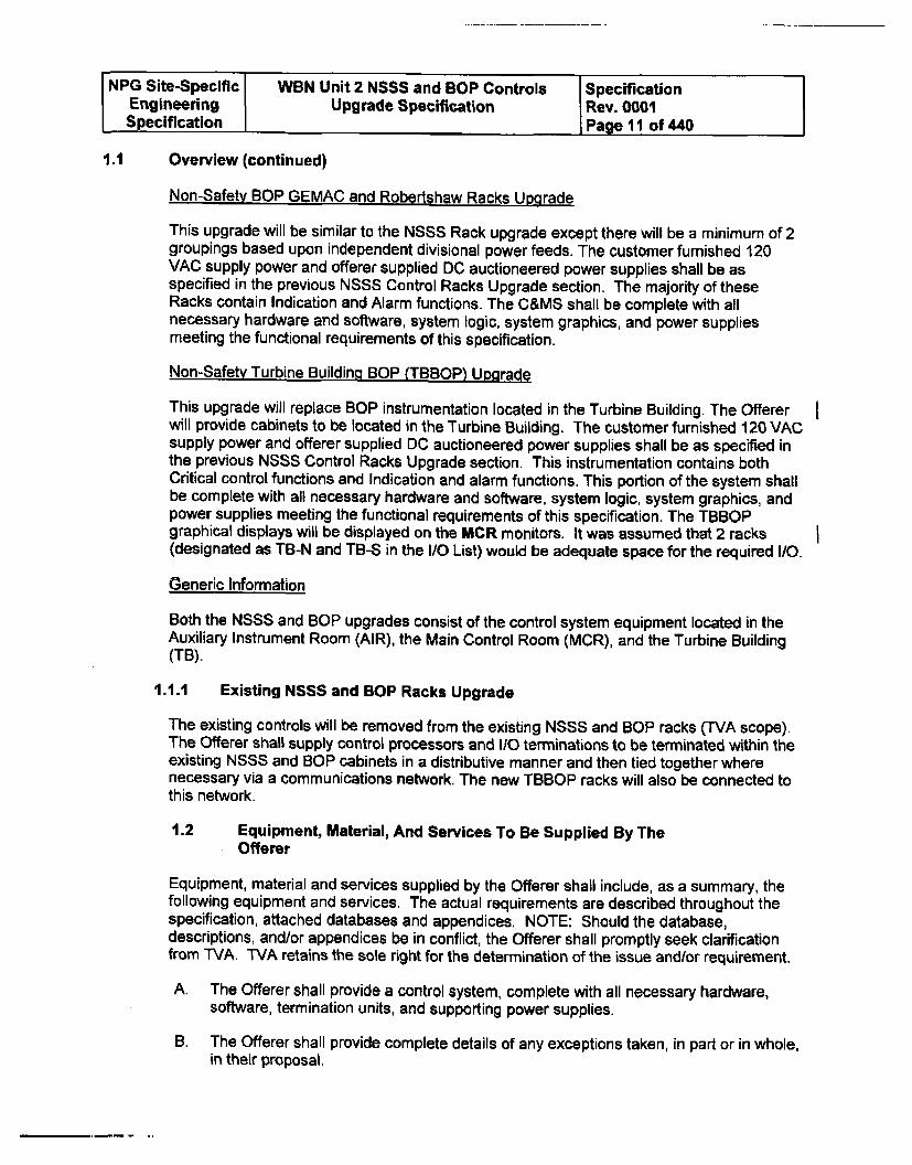
1.1 Overview (continued)
Non-Safety BOP GEMAC and Robertehaw Racks Upgrade
This upgrade will be similar to the NSSS Rack upgrade except there will be a minimum of 2groupings based upon independent divisional power feeds. The customer furnished 120VAC supply power and offerer supplied DC auctioneered power supplies shall be asspecified in the previous NSSS Control Racks Upgrade section. The majority of theseRacks contain Indication and Alarm functions. The C&MS shall be complete with allnecessary hardware and software, system logic, system graphics, and power suppliesmeeting the functional requirements of this specification.
Non-Safety Turbine Building BOP (TBBOP) Up-grade
This upgrade will replace BOP instrumentation located in the Turbine Building. The Offererwill provide cabinets to be located in the Turbine Building. The customer furnished 120 VACsupply power and offerer supplied DC auctioneered power supplies shall be as specified inthe previous NSSS Control Racks Upgrade section. This instrumentation contains bothCritical control functions and Indication and alarm functions. This portion of the system shallbe complete with all necessary hardware and software, system logic, system graphics, andpower supplies meeting the functional requirements of this specification. The TBBOPgraphical displays will be displayed on the MCR monitors. It was assumed that 2 racks(designated as TB-N and TB-S in the I/O List) would be adequate space for the required I/O.
Generic Information
Both the NSSS and BOP upgrades consist of the control system equipment located in theAuxiliary Instrument Room (AIR), the Main Control Room (MCR), and the Turbine Building(TB).
1.1.1 Existing NSSS and BOP Racks Upgrade
The existing controls will be removed from the existing NSSS and BOP racks (TVA scope).The Offerer shall supply control processors and 1/0 terminations to be terminated within theexisting NSSS and BOP cabinets in a distributive manner and then tied together wherenecessary via a communications network. The new TBBOP racks will also be connected tothis network.
1.2 Equipment, Material, And Services To Be Supplied By TheOfferer
Equipment, material and services supplied by the Offerer shall include, as a summary, thefollowing equipment and services. The actual requirements are described throughout thespecification, attached databases and appendices. NOTE: Should the database,descriptions, and/or appendices be in conflict, the Offerer shall promptly seek clarificationfrom TVA. TVA retains the sole right for the determination of the issue and/or requirement.
A. The Offerer shall provide a control system, complete with all necessary hardware,software, termination units, and supporting power supplies.
B. The Offerer shall provide complete details of any exceptions taken, in part or in whole,in their proposal,
NPG Site-Specific WBN Unit 2 NSSS and BOP Controls SpecificationEngineering Upgrade Specification Rev. 0001Specification Page 12 of 440
1.2 Equipment, Material, And Services To Be Supplied By The Offerer(continued)
C. The Offerer shall provide engineering work stations, data storage and retrieval drops,printers, and interface hardware and software as described herein, or as may bereasonably required to meet the intent of this specification.
D. The Offerer shall provide project management, project engineering, systemengineering, software engineering, design, programming, graphics configuration andimplementation effort to support the project,
E. The Offerer shall supply complete logic diagrams and supporting descriptions detailingthe system's control actions using symbology consistent with SAMA/ISAstandards for continuous (analog) and discrete (Boolean) logic. This method isunderstood to be to the satisfaction of the Lead Electrical Engineer (LEE).
F. The Offerer shall provide, in their proposal, a list of spare parts and recommendedquantities to be maintained in the TVA storeroom. The spare parts list shall containthe Offerer's part number, the OEM name and OEM part number, and the proposedunit pricing for each part listed. Inclusion of the OEM information is MANDATORY.
G. The Offerer shall provide any special tools, test equipment and software required forthe installation, and continued operation and maintenance of the purchasedequipment not commonly available in a power plant. The special tools, test equipmentor software shall be supplied as part of the base price for this project, and will bepermanently retained for TVA's use at WBN 2.
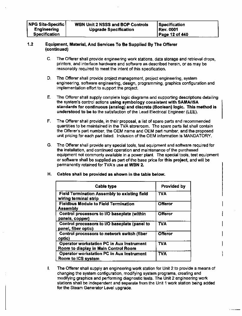
H. Cables shall be provided as shown in the table below.
Cable type Provided by
Field Termination Assembly to existing field TVAwiring terminal stripFieldbus Module to Field Termination Offeror
AssemblyControl processors to 110 baseplate (within Offerorpanels, copper)Control processors to 110 baseplate (panel to TVApanel, fiber optic)Control processors to network switch (fiber Offeroroptic)Operator workstation PC in Aux Instrument TVA
Room to display in Main Control RoomOperator workstation PC in Aux Instrument TVA
Room to ICS system _
The Offerer shall supply an engineering work station for Unit 2 to provide a means ofchanging the system configuration, modifying system programs, creating andmodifying graphics and performing diagnostic tests. The Unit 2 engineering workstations shall be independent and separate from the Unit 1 work station being addedfor the Steam Generator Level upgrade.
I
NPG Site-Specific WBN Unit 2 NSSS and BOP Controls SpecificationEngineering Upgrade Specification Rev. 0001Specification Page 13 of 440
1.2 Equipment, Material, And Services To Be Supplied By The Offerer(continued)
J. The Offerer shall supply 2 (touch screen will not be utilized) displays. The displaysshall be a minimum of 19 inches in size (20 inches preferred and shall be quoted) andshall be capable of providing input to control functions.
K. The Offerer shall provide an option to shall supply 4 (touch screen will not be utilized)displays. The displays shall be a minimum of 19 inches in size (20 inches preferredand shall be quoted) and shall be capable of providing input to control functions.
L, The Offerer shall supply 2 new free standing instrument racks complete withnecessary I/O for the Turbine Building BOP equipment.
M. The Offerer shall perform an open and closed loop factory test on the entire controlsystem. This shall be accomplished in two phases. Phase One is totally the Offerer'sresponsibility to provide a completely engineered, configured and tested system.Phase One shall include verification and validation of all system 110 by the Offerorand shall ensure that the application software and operator interface configurationsare complete, accurate, and ready for inspection by TVA during Phase Two. PhaseTwo shall be conducted by the Offerer per the factory acceptance test (Section2.8.3M) and will be witnessed by the Engineer. This shall include checking 100percent of the 110, all single point failures, control loop functionality, or other tests asrequired by the Engineer to ensure compliance with the specification. No equipmentshall be released for shipment without satisfactory completion of the Phase Two test,unless specifically waived, in writing, by the LEE. A closed loop model shall be usedfor closed loop testing and does not require a high level of plant response fidelity, butit should be capable of exercising all control loops as an integrated system (with bothprimary and secondary side responses). It shall able to test associated functions suchas input validation algorithms to ensure a correct control system response (ie., PIDinput to output relationship, etc.). The use of engineered lag/delays to simulate plantresponse feedback delays is acceptable (first principal modeling is not required).
N. The Offerer shall provide services of a qualified field representative(s) for systemstart-up and tuning. These services shall include all power-up checks according to theOfferer's recommended practices and shall be scheduled at the Engineer'sconvenience.
The Offerer shall provide a man hour rate for these services along with per diem
costs.
0. The Offerer shall provide training as outlined in Section 2.8.4
1.3 Equipment, Material, and Services To Be Supplied By Others
The following items are not included under the scope of this specification, and have been, orwill be performed by Others:
A. TVA will furnish the Offerer, without charge, necessary copies of the contract andspecifications as may be reasonably required for performance of the work.
B. TVA will provide the Offerer with any technical data on file which TVA considersessential for completion of the work required.
NPG Site-Specific WBN Unit 2 NSSS and BOP Controls SpecificationEngineering Upgrade Specification Rev. 0001Specification Page 14 of 440
1.3 Equipment, Material, and Services To Be Supplied By Others
(continued)
C. Receiving, storage, and field installation of the control system.
D. All field wiring external to the control system with the control system boundary endingat the existing rack terminal block. (Note: Pre-fabricated cables, such as FBM toprocessor cable, specified in this specification are to be supplied by the Offerer, butwill be installed by TVA if routed outside of the cabinet or console.)
1.4 Project Review Meetings
The Offerer shall include in his base offer attendance at monthly project review meetings.These meetings will commence with the kick-off meeting and occur on a scheduled monthlybasis up to one month after return of the unit to electrical generation. Meeting agendas willinclude schedule, technical and commercial issues to ensure continued progress of theproject, specific accomplishments of the past month and action/objectives to be completedin the coming month. These meetings are site specific and may not be held at the sametime or place.
The Offerer shall be responsible for generation and transmission to the Engineer (within 1week of meetings) of formal meeting minutes for the Engineer's review, and will contain aproposed agenda and topics list for the next meeting. Following receipt and review of theOfferer minutes, an official meeting minutes will be generated by the Engineer anddistributed to all participants. This process is implemented to ensure that TVA's and theOfferer's perspectives on all issues are thoroughly understood.
The time and place of all meetings will be established by WVA at a TVA facility unless theEngineer determines that the meeting objectives would be better accomplished at anotherlocation.
1.5 Target Project Schedule
The Offerer shall prepare (and maintain for the life of the project) a working projectschedule. The project schedule milestones, events and dates are to be the basis of workingproject schedule. The Offerer's project schedule shall be submitted for approval to theEngineer. The key areas for scheduling are receipt of information required for determinationof contract compliance, support of balance of plant design, and pre-outage receipt ofmaterials.
Refer to the contract milestone schedule for required dates.
2.0 INSTRUCTIONS FOR PROPOSAL
The functional requirements, description of operation and control requirements includedherein establish the criteria for the control system. However, it is not intended to limit theoperation, functions, and safeguards to those either mentioned or implied. The Offerer shallmake any additional suggestions or recommendations that will improve the proposedoperational procedures or method of control. All the system engineering and hardwareneeded to constitute a fully integrated, complete and operable start-up; shut-down and on-line control system shall be supplied by the Offerer whether or not specifically detailedherein.
NPG Site-Specific WBN Unit 2 NSSS and BOP Controls SpecificationEngineering Upgrade Specification Rev. 0001Specification Page 15 of 440
2.1 Bases for Technical Evaluation
Proposals submitted for consideration will be evaluated based on the criteria listed belowbut not necessarily in the order listed.
A. Previous Experience
The Offerer's previous experience with similar applications, experience with thenuclear industry, TVA nuclear specific experience, and industry wide similarapplications will be considered. Offerer must have previous demonstrated experiencein the specific area of digital SGL control systems (see Section 4.0 of thisspecification).
B. Expansion Capability/Flexibility
The ability of the Offerer's proposed system to be expanded, utilizing built in sparecapacity, and ease of integration with the plant's Reactor Protection Systems, PlantAnnunciator Systems, and the plant process computer "Integrated Computer System"(ICS) will be considered.
C. Ease of Maintenance/Modification
The ability of the Offerer's proposed system to perform on-line maintenance andmodification while the system is operating, self-diagnostic capability, reuse of existingcabling, and ease of engineering modifications will be considered.
D. Operator Interface
The Man-Machine Interface of the Offerer's proposed system, including such aspectsas availability of data, simplicity of control, similarity to plant process computerdisplays, and flexibility of configuration will be considered.
E. Redundancy/Fail-Safe
The ability of the Offerer's proposed system to tolerate failures, including multiplefailures, without compromising normal operation will be considered.
F. Product Support
The expected product lifetime of the Offerer's proposed system and previousexperience with the Offerer as relates to product support will be considered.
G. Schedule
The ability of the Offerer to meet the required schedule will be considered.
2.2 WBN Simulator Upgrade
NPG Site-Specific WBN Unit 2 NSSS and BOP Controls SpecificationEngineering Upgrade Specification Rev. 0001Specification Page 16 of 440
2.2 WBN Simulator Upgrade (continued)
The Offerer shall also provide a proposal for any hardware/software required to modify theWBN Main Control Room Simulator to reflect the changes that will result from the proposedControl system upgrade. The preferred implementation method is to use "faceplate" typeinstruments to be driven by the simulator computer, but a full Control System with interfacebox can be proposed. Any hardware/software proposed for the MCR simulator shallincorporate the ability to allow the simulator operation to be "frozen" and initialized to apredetermined state. See Appendix D for WBN detailed requirements. Differences resultingfrom the partial WBN Unit 1 SGL upgrade must be integrated with the Unit 2 changes. Thescope included within the current WBN I project shall not be duplicated within thisproposal.
2.3 Multi-Unit Proposal
To be determined later.
2.4 Architectural Engineering (AE) Services
Omitted
2.6 Hardware Requirements
The hardware requirements associated with the proposed system are as follows:
A. The proposed system shall be a microprocessor based distributed system.
B. The proposed system shall have a Mean Time Between Failure (MTBF) of greaterthan 40 years. A failure for this case is considered the loss of system ability toautomatically control. The Offerer shall provide MTBF data for the proposed systemand the rationale behind it.
C. The proposed system shall have a Mean Time To Repair (MTTR) of less than 2 hours.The Offerer shall provide MTTR data for the proposed system and the rationalebehind it.
D. The proposed system shall be capable of being powered from two 120V AC 60 Hz(non-synchronized) voltage sources.
E. The proposed system shall provide power for 4 to 20 ma inputs/outputs and specifieddigital outputs.
F. All system inputs, including power inputs, shall be filtered to remove high frequencyEMI/RFI, and process noise (see required testing in section 3.11.1).
G. The operator handstations for the proposed system shall be labeled "NM" forAuto/Manual. Other proposed labeling schemes shall be noted in the Offerer's bidproposal for evaluation.
NPG Site-Specific WBN Unit 2 NSSS and BOP Controls SpecificationEngineering Upgrade Specification Rev. 0001Specification Page 17 of 440
2.5 Hardware Requirements (continued)
H. All rack mounted hardware, unless otherwise noted, is to be located in existingAuxiliary Instrument Room (AIR) cabinets/Racks and the MCR or in new rackssupplied under this proposal for the TBBOP. Each Offerer shall assume that allcomponents are front mounted into the racks. Unless otherwise noted, all indicatorsand handstations will be located in the MCR. The TBBOP rack mounted hardware willbe located in the Turbine Building in new cabinets and will have or supply localhandstations and indications as defined in the 110 listing and will be mounted inspecific locations TBD by TVA.
For the Engineering Workstations and operator display units (ODUs), removablestorage devices, mouse/trackballs, and keyboards shall be provided for maintenanceand operations use.
J. The hardware supplied for mounting in the existing panels shall be configured in sucha way as to simplify installation. For example, component racks should be suppliedwith all hardware necessary to allow for direct bolt-in installation without panelmodifications. TVA will provide plans for clear mounting space in existing cabinetsand to be verified by the Offerer prior to final hardware design drawings anddocuments are issued (prior to 100% Design Review).
K. An Engineering Workstation system interface and printer interface shall be providedfor remote installation. The Offerer shall specify the maximum distance thisEngineering Workstation and Operator Console may be located from the controlsystem. Security shall be provided to prevent unauthorized modification of systemprogramming or operational parameters.
L. The proposed system configuration shall be tested and demonstrated to be resistantto EMI/RFI induced malfunctions as specified in TVA Standard Spec SS-El 8.14.01.However, the Offerer may substitute his standard EMI/RFI test if approved by WVA.Previously approved reports were only conditionally approved by Brown Ferry Nuclearand are not directly applicable to the WBN C&MS application. The SQN/WBN upgradeapproval may be used to fulfill this requirement when completed.
M. The proposed system shall be capable of interfacing with the plant IntegratedComputer System (ICS).
1. The proposed system hardware interface to the ICS shall be twisted pair or fiberoptic Ethernet conforming to IEEE Standard 802.3
2. The proposed system hardware interface protocol to the ICS shall be TCP/IPusing OPC format. See Figure 4 of the proposed control system and ICSinterface.
3. The proposed system shall transmit analog data with the following information:
Point IdentifierPoint ValuePoint Quality (e.g. bad, off scan, out of range, alarm, etc.)
NPG Site-Specific WBN Unit 2 NSSS and BOP Controls SpecificationEngineering Upgrade Specification Rev. 0001Specification Page 18 of 440
2.5 Hardware Requirements (continued)
4. The proposed system shall transmit digital data with the following information:
Point IdentifierPoint ValuePoint Quality (e.g. bad, off scan, out of range, alarm, etc.)
or
Packed digitals with 1 bit per point. Packing is acceptable only if point quality isalso transmitted.
5. The proposed system shall associate a time stamp with each data pointcorresponding to the time the data was acquired and transmit this time stamp withthe point value. If all values in a transmission are acquired within the update rate(as specified in the Functional Requirements in Sections 4 through 12below) then a single time stamp may be associated with the data block ratherthan individual points.
6. The proposed system shall be capable of transmitting updates of all data points(including existing and spare capacity) at a rate that meets the FunctionalRequirements of Sections 4 through 12 below. Faster update rates aredesirable for selected points. The system must provide the capability to slowdown or throttle the data transfer to the minimum rate if necessary.
7. The proposed system shall be capable of accepting a time synchronization signal(either over the Ethernet or an IRIG-B signal) from the ICS and setting itstimebase to this value. However, the system must not be dependent upon thissignal for time stamping of data or other time related operations.
8. The proposed system shall be capable of notifying the ICS of internal self-testresults/values.
9. A failure in the ICS shall not affect the control system. Example: ICS failureresults in repeated requests for information shall not affect the response time ofthe control system and shall be proven by test. Testing shall be based upon typeof communication buffering device (e.g. firewall), ICS broadcast capability,communication and protocol being used. Any required configuration limits (e.g.,amount of allowable requests within a specific time and/or authorized IP requests)for the buffering device shall be documented and placed under configurationcontrol.
N. The proposed system shall have redundant error checking computation processors ormodules.
0. The proposed system shall have installed spare CPU, memory, communications, andother system capacities reserved to support future expansion. See Section 3.2.1 H forthe specific requirements. The Offerer shall specify the spare capacity of the proposedsystem. Additional spare capacity shall be offered as an option. Offerer shall identifywhere spare capability requirements cannot be met without the addition of additionalcabinets.
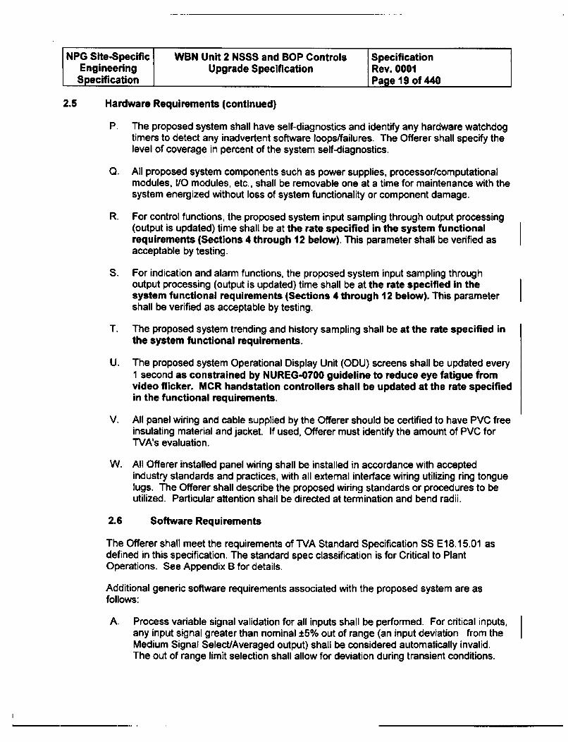
NPG Site-Specific WBN Unit 2 NSSS and BOP Controls SpecificationEngineering Upgrade Specification Rev. 0001Specification Page 19 of 440
2.5 Hardware Requirements (continued)
P. The proposed system shall have self-diagnostics and identify any hardware watchdogtimers to detect any inadvertent software loops/failures. The Offerer shall specify thelevel of coverage in percent of the system self-diagnostics.
Q. All proposed system components such as power supplies, processor/computationalmodules, I/O modules, etc., shall be removable one at a time for maintenance with thesystem energized without loss of system functionality or component damage.
R. For control functions, the proposed system input sampling through output processing(output is updated) time shall be at the rate specified in the system functionalrequirements (Sections 4 through 12 below). This parameter shall be verified asacceptable by testing.
S. For indication and alarm functions, the proposed system input sampling throughoutput processing (output is updated) time shall be at the rate specified in thesystem functional requirements (Sections 4 through 12 below). This parametershall be verified as acceptable by testing.
T. The proposed system trending and history sampling shall be at the rate specified inthe system functional requirements.
U. The proposed system Operational Display Unit (ODU) screens shall be updated every1 second as constrained by NUREG-0700 guideline to reduce eye fatigue fromvideo flicker. MCR handstation controllers shall be updated at the rate specifiedin the functional requirements.
V. All panel wiring and cable supplied by the Offerer should be certified to have PVC freeinsulating material and jacket. If used, Offerer must identify the amount of PVC forTVA's evaluation.
W. All Offerer installed panel wiring shall be installed in accordance with acceptedindustry standards and practices, with all external interface wiring utilizing ring tonguelugs. The Offerer shall describe the proposed wiring standards or procedures to beutilized. Particular attention shall be directed at termination and bend radii.
2.6 Software Requirements
The Offerer shall meet the requirements of TVA Standard Specification SS E18.15.01 asdefined in this specification. The standard spec classification is for Critical to PlantOperations. See Appendix B for details.
Additional generic software requirements associated with the proposed system are asfollows:
A. Process variable signal validation for all inputs shall be performed. For critical inputs,any input signal greater than nominal ±5% out of range (an input deviation from theMedium Signal Select/Averaged output) shall be considered automatically invalid.The out of range limit selection shall allow for deviation during transient conditions.
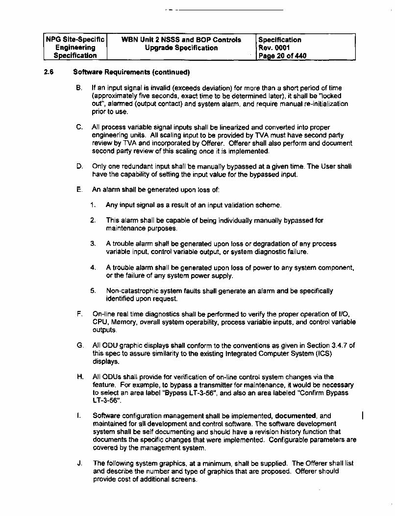
NPG Site-Specific WBN Unit 2 NSSS and BOP Controls SpecificationEngineering Upgrade Specification Rev. 0001Specification Page 20 of 440
2.6 Software Requirements (continued)
B. If an input signal is invalid (exceeds deviation) for more than a short period of time(approximately five seconds, exact time to be determined later), it shall be "lockedout", alarmed (output contact) and system alarm, and require manual re-initializationprior to use.
C. All process variable signal inputs shall be linearized and converted into properengineering units. All scaling input to be provided by TVA must have second partyreview by TVA and incorporated by Offerer. Offerer shall also perform and documentsecond party review of this scaling once it is implemented.
D. Only one redundant input shall be manually bypassed at a given time. The User shall
have the capability of setting the input value for the bypassed input.
E. An alarm shall be generated upon loss of:
1. Any input signal as a result of an input validation scheme.
2. This alarm shall be capable of being individually manually bypassed formaintenance purposes.
3. A trouble alarm shall be generated upon loss or degradation of any processvariable input, control variable output, or system diagnostic failure.
4. A trouble alarm shall be generated upon loss of power to any system component,or the failure of any system power supply.
5. Non-catastrophic system faults shall generate an alarm and be specificallyidentified upon request.
F. On-line real time diagnostics shall be performed to verify the proper operation of I/O,CPU, Memory, overall system operability, process variable inputs, and control variableoutputs.
G. All ODU graphic displays shall conform to the conventions as given in Section 3.4.7 ofthis spec to assure similarity to the existing Integrated Computer System (ICS)displays.
H. All ODUs shall provide for verification of on-line control system changes via thefeature. For example, to bypass a transmitter for maintenance, it would be necessaryto select an area label "Bypass LT-3-56", and also an area labeled "Confirm BypassLT-3-56".
1. Software configuration management shall be implemented, documented, andmaintained for all development and control software. The software developmentsystem shall be self documenting and should have a revision history function thatdocuments the specific changes that were implemented. Configurable parameters arecovered by the management system.
J. The following system graphics, at a minimum, shall be supplied. The Offerer shall listand describe the number and type of graphics that are proposed. Offerer shouldprovide cost of additional screens.
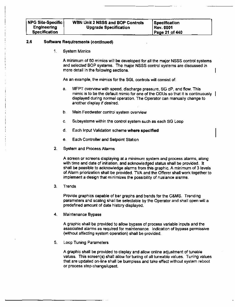
NPG Site-Specific WBN Unit 2 NSSS and BOP Controls SpecificationEngineering Upgrade Specification Rev. 0001
, Specification I Page 21 of 440
2.6 Software Requirements (continued)
I System Mimics
A minimum of 60 mimics will be developed for all the major NSSS control systemsand selected BOP systems. The major NSSS control systems are discussed inmore detail in the following sections.
As an example, the mimics for the SGL controls will consist of:
a. MFPT overview with speed, discharge pressure, SG dP, and flow. Thismimic is to be the default mimic for one of the ODUs so that it is continuouslydisplayed during normal operation. The Operator can manually change toanother display if desired.
b. Main Feedwater control system overview
c. Subsystems within the control system such as each SG Loop
d. Each Input Validation scheme where specified
e. Each Controller and Setpoint Station
2. System and Process Alarms
A screen or screens displaying at a minimum system and process alarms, alongwith time and date of initiation, and acknowledged status shall be provided. Itshall be possible to acknowledge alarms from this graphic. A minimum of 3 levelsof Alarm priorization shall be provided. TVA and the Offerer shall work together toimplement a design that minimizes the possibility of nusiance alarms.
3. Trends
Provide graphics capable of bar graphs and trends for the C&MS. Trendingparameters and scaling shall be selectable by the Operator and shall open will apredefined amount of data history displayed.
4. Maintenance Bypass
A graphic shall be provided to allow bypass of process variable inputs and theassociated alarms as required for maintenance. Indication of bypass permissive(without affecting system operation) shall be provided.
5. Loop Tuning Parameters
A graphic shall be provided to display and allow online adjustment of tunablevalues. This screen(s) shall allow for tuning of all tuneable values. Tuning valuesthat are updated on-line shall be bumpless and take effect without system rebootor process step change/upset.
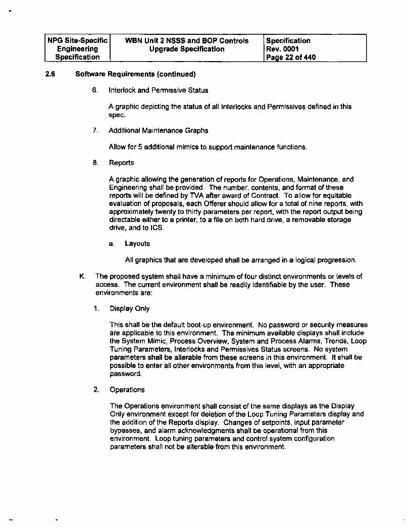
NPG Site-Specific WBN Unit 2 NSSS and BOP Controls SpecificationEngineering Upgrade Specification Rev. 0001Specification Page 22 of 440
2.6 Software Requirements (continued)
6. Interlock and Permissive Status
A graphic depicting the status of all Interlocks and Permissives defined in thisspec.
7. Additional Maintenance Graphs
Allow for 5 additional mimics to support maintenance functions.
8. Reports
A graphic allowing the generation of reports for Operations, Maintenance, andEngineering shall be provided. The number, contents, and format of thesereports will be defined by TVA after award of Contract. To allow for equitableevaluation of proposals, each Offerer should allow for a total of nine reports, withapproximately twenty to thirty parameters per report, with the report output beingdirectable either to a printer, to a file on both hard drive, a removable storagedrive, and to ICS.
a. Layouts
All graphics that are developed shall be arranged in a logical progression.
K. The proposed system shall have a minimum of four distinct environments or levels ofaccess. The current environment shall be readily identifiable by the user. Theseenvironments are:
1. Display Only
This shall be the default boot-up environment. No password or security measuresare applicable to this environment. The minimum available displays shall includethe System Mimic, Process Overview, System and Process Alarms, Trends, LoopTuning Parameters, Interlocks and Permissives Status screens. No systemparameters shall be alterable from these screens in this environment. It shall bepossible to enter all other environments from this level, with an appropriatepassword.
2. Operations
The Operations environment shall consist of the same displays as the DisplayOnly environment except for deletion of the Loop Tuning Parameters display andthe addition of the Reports display, Changes of setpoints, input parameterbypasses, and alarm acknowledgments shall be operational from thisenvironment. Loop tuning parameters and control system configurationparameters shall not be alterable from this environment.
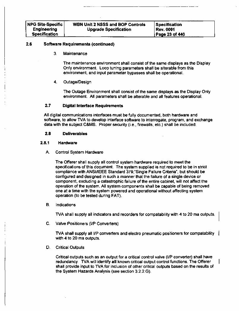
NPG Site-Specific WBN Unit 2 NSSS and BOP Controls SpecificationEngineering Upgrade Specification Rev. 0001Specification Page 23 of 440
2.6 Software Requirements (continued)
3. Maintenance
The maintenance environment shall consist of the same displays as the DisplayOnly environment. Loop tuning parameters shall be alterable from thisenvironment, and input parameter bypasses shall be operational.
4. Outage/Design
The Outage Environment shall consist of the same displays as the Display Onlyenvironment. All parameters shall be alterable and all features operational.
2.7 Digital Interface Requirements
All digital communications interfaces must be fully documented, both hardware andsoftware, to allow TVA to develop interface software to interrogate, program, and exchangedata with the subject C&MS. Proper security (i.e., firewalls, etc.) shall be included.
2.8 Deliverables
2.8.1 Hardware
A. Control System Hardware
The Offerer shall supply all control system hardware required to meet thespecifications of this document. The system supplied is not required to be in strictcompliance with ANSI/IEEE Standard 379,"Single Failure Criteria", but should beconfigured and designed in such a manner that the failure of a single device orcomponent, excluding a catastrophic failure of the entire cabinet, will not affect theoperation of the system. All system components shall be capable of being removedone at a time with the system powered and operational without affecting systemoperation (to be tested during FAT).
B. Indications
TVA shall supply all indicators and recorders for compatability with 4 to 20 ma outputs.
C. Valve Positioners (I/P Converters)
TVA shall supply all I/P converters and electro pneumatic positioners for compatabilitywith 4 to 20 ma outputs.
D. Critical Outputs
Critical outputs such as an output for a critical control valve (i1P converter) shall haveredundancy. TVA will identify all known critical output control functions. The Offerershall provide input to TVA for inclusion of other critical outputs based on the results ofthe System Hazards Analysis (see section 3.2.2.G).
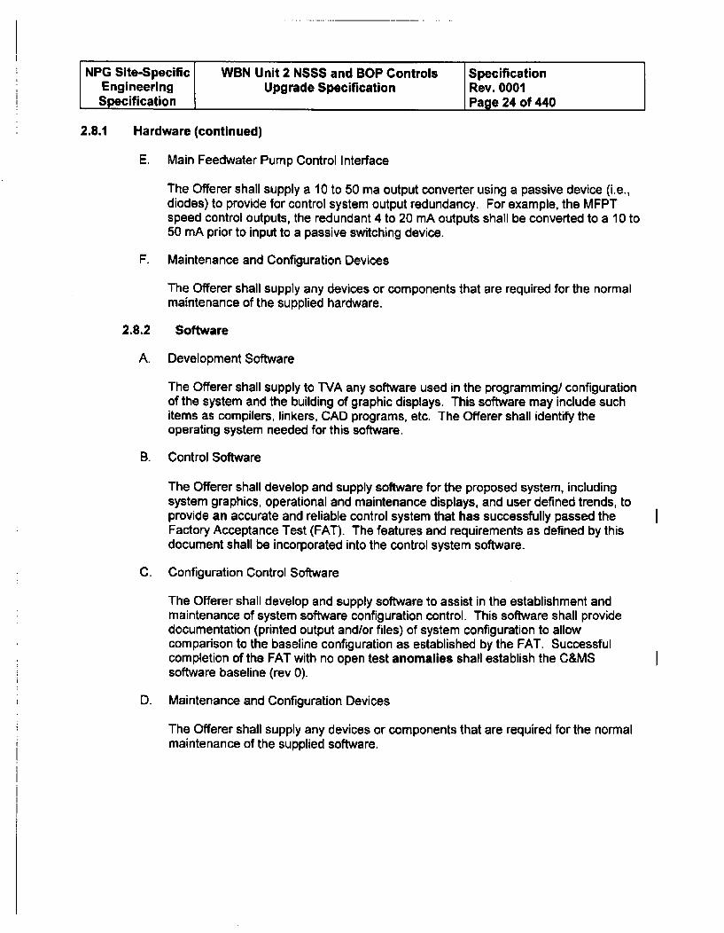
NPG Site-Specific WBN Unit 2 NSSS and BOP Controls SpecificationEngineering Upgrade Specification Rev. 0001Specification Page 24 of 440
2.8.1 Hardware (continued)
E. Main Feedwater Pump Control Interface
The Offerer shall supply a 10 to 50 ma output converter using a passive device (i.e.,diodes) to provide for control system output redundancy. For example, the MFPTspeed control outputs, the redundant 4 to 20 mA outputs shall be converted to a 10 to50 mA prior to input to a passive switching device.
F. Maintenance and Configuration Devices
The Offerer shall supply any devices or components that are required for the normalmaintenance of the supplied hardware.
2.8.2 Software
A. Development Software
The Offerer shall supply to TVA any software used in the programming/ configurationof the system and the building of graphic displays. This software may include suchitems as compilers, linkers, CAD programs, etc. The Offerer shall identify theoperating system needed for this software.
B. Control Software
The Offerer shall develop and supply software for the proposed system, includingsystem graphics, operational and maintenance displays, and user defined trends, toprovide an accurate and reliable control system that has successfully passed theFactory Acceptance Test (FAT). The features and requirements as defined by thisdocument shall be incorporated into the control system software.
C. Configuration Control Software
The Offerer shall develop and supply software to assist in the establishment andmaintenance of system software configuration control. This software shall providedocumentation (printed output and/or files) of system configuration to allowcomparison to the baseline configuration as established by the FAT. Successfulcompletion of the FAT with no open test anomalies shall establish the C&MSsoftware baseline (rev 0).
D. Maintenance and Configuration Devices
The Offerer shall supply any devices or components that are required for the normalmaintenance of the supplied software.
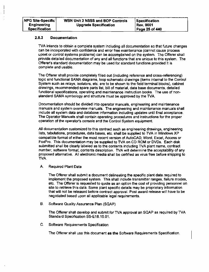
NPG Site-Specific WBN Unit 2 NSSS and SOP Controls SpecificationEngineering Upgrade Specification Rev. 0001Specification I Page 25 of 440
2.8.3 Documentation
TVA intends to obtain a complete system including all documentation so that future changescan be incorporated with confidence and error free maintenance (cannot cause processupset or control systems problems) can be accomplished on the system. The Offerer shallprovide detailed documentation of any and all functions that are unique to this system. TheOfferers standard documentation may be used for standard functions provided it iscomplete and usable.
The Offerer shall provide completely filled out (including reference and cross-referencing)logic and functional SAMA diagrams, loop schematic drawings (items internal to the ControlSystem such as relays, isolators, etc. are to be shown to the field terminal blocks), cabinetdrawings, recommended spare parts list, bill of material, data base documents, detailedfunctional specifications, operating and maintenance instruction books. The use of non-standard SAMA symbology and structure must be approved by the WVA.
Documentation should be divided into operator manuals, engineering and maintenancemanuals and system overview manuals. The engineering and maintenance manuals shallinclude all system data and database information including updates until final acceptance.The Operator Manuals shall contain operating procedures and instructions for the properoperation of the operator's console and the Control System equipment.
All documentation customized to this contract such as engineering drawings, engineeringlists, tabulations, procedures, data bases, etc. shall be supplied to TVA in Windows XPcompatible format of either the most recent version of AutoCAD, Word, Excel, Access orFoxPro. This documentation may be supplied to TVA on CD ROM or DVDs. Each disksubmitted shall be clearly labeled as to the contents including TVA plant name, contractnumber, software format, contents description. TVA will determine the acceptability of anyproposed alternative. All electronic media shall be certified as virus free before shipping toTVA.
A. Required Plant Data
The Offerer shall submit a document delineating the specific plant data required toimplement the proposed system. This shall include transmitter ranges, failure modes,etc. The Offerer is requested to quote as an option the cost of providing personnel onsite to retrieve this data. Some plant specific details may be proprietary informationthat will not be released before contract approval. Post award release will have to benegotiated based upon all applicable legal requirements.
B. Software Quality Assurance Plan (SQAP)
The Offerer shall develop and submit for TVA approval an SQAP as required by WVAStandard Specification SS-EI8.15.01.
C. Software Requirements Specification
The Offerer shall use this document as the Software Requirements Specification.
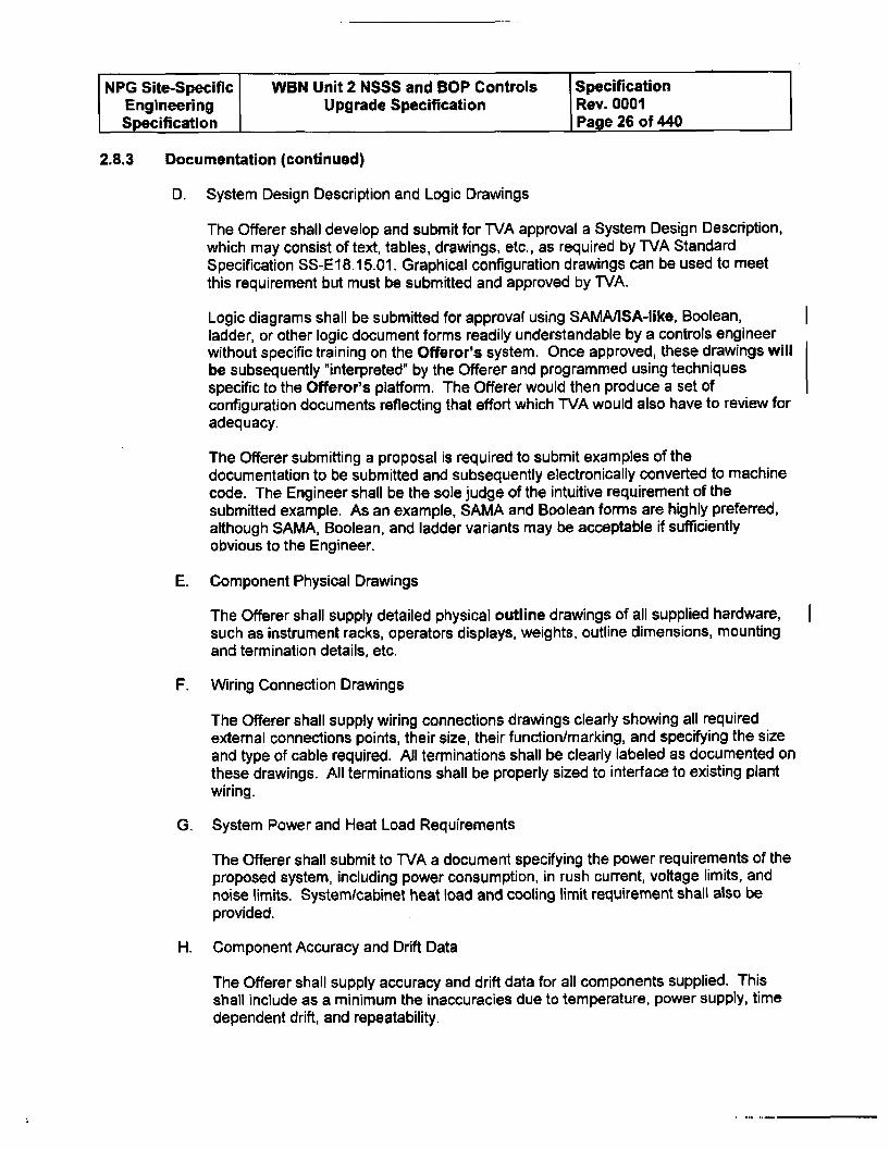
NPG Site-Specific WBN Unit 2 NSSS and BOP Controls SpecificationEngineering Upgrade Specification Rev. 0001Specification Page 26 of 440
2.8.3 Documentation (continued)
D. System Design Description and Logic Drawings
The Offerer shall develop and submit for TVA approval a System Design Description,which may consist of text, tables, drawings, etc., as required by TVA StandardSpecification SS-EI8.15.01. Graphical configuration drawings can be used to meetthis requirement but must be submitted and approved by TVA.
Logic diagrams shall be submitted for approval using SAMM/ISA-like, Boolean,ladder, or other logic document forms readily understandable by a controls engineerwithout specific training on the Offeror's system. Once approved, these drawings willbe subsequently "interpreted" by the Offerer and programmed using techniquesspecific to the Offeror's platform. The Offerer would then produce a set ofconfiguration documents reflecting that effort which TVA would also have to review foradequacy.
The Offerer submitting a proposal is required to submit examples of thedocumentation to be submitted and subsequently electronically converted to machinecode. The Engineer shall be the sole judge of the intuitive requirement of thesubmitted example. As an example, SAMA and Boolean forms are highly preferred,although SAMA, Boolean, and ladder variants may be acceptable if sufficientlyobvious to the Engineer.
E. Component Physical Drawings
The Offerer shall supply detailed physical outline drawings of all supplied hardware,such as instrument racks, operators displays, weights, outline dimensions, mountingand termination details, etc.
F. Wiring Connection Drawings
The Offerer shall supply wiring connections drawings clearly showing all requiredexternal connections points, their size, their function/marking, and specifying the sizeand type of cable required. All terminations shall be clearly labeled as documented onthese drawings. All terminations shall be properly sized to interface to existing plantwiring.
G. System Power and Heat Load Requirements
The Offerer shall submit to WVA a document specifying the power requirements of theproposed system, including power consumption, in rush current, voltage limits, andnoise limits. System/cabinet heat load and cooling limit requirement shall also beprovided.
H. Component Accuracy and Drift Data
The Offerer shall supply accuracy and drift data for all components supplied. Thisshall include as a minimum the inaccuracies due to temperature, power supply, timedependent drift, and repeatability.
NPG Site-Specific WBN Unit 2 NSSS and BOP Controls SpecificationEngineering Upgrade Specification Rev. 0001Specification Page 27 of 440
2.8.3 Documentation (continued)
1. Seismic Qualification Information
See Appendix H for seismic response curves to be used in conjunction withthese requirements,
1. Control Cabinet
Where existing cabinets are not used, the Offerer shall supply a cabinet tohouse control system hardware, power supplies, and 110 hardware. The cabinetshall be similar to existing Foxboro control cabinets. Offerer shall performwalkdown to scope out size, placement, and mounting.
Cabinet and processor loading should allow future expansion capability within theexisting cabinets. The Offerer shall provide component information such as size,weight, center of gravity, materials of construction, and mounting materials. TheOfferer shall demonstrate cabinet seismic structural integrity in accordance withWVA Design Criteria No. WB-DC-40-31.13, Rev. 4, "Seismic Qualification ofCategory I(L) Fluid System Components and Electrical or MechanicalEquipment."
The Offerer shall verify sufficient clearance is available to transport controlcabinets through existing entry ways.
2. Control Racks
Remote I/O hardware must be installed in existing process control systeminstrument racks with a minimum impact on field terminations and cabinetstructural configuration.
Offerer shall evaluate the rack structure (including on-site visits) and provide allnecessary mounting hardware. If an enclosure is supplied, the Offerer shalldemonstrate seismic structural integrity in accordance with TVA Design CriteriaNo. WB-DC-40-31.13, Rev. 4, "Seismic Qualification of Category I(L) FluidSystem Components and Electrical or Mechanical Equipment."
3. Handstations/Operator Console
The MCR handstations must be installed within the existing main control boardcutouts with a minimum impact on the control boards. The Offerer shall supply theequipment qualified for the as installed configuration in compliance with WBNDesign Criteria, WB-DC-40-31.13, "Seismic Qualification of Category 1 (L) FluidSystem Components and Electrical or Mechanical Equipment". TVA shall selecthandstations.
NPG Site-Specific WBN Unit 2 NSSS and BOP Controls Specification
Engineering Upgrade Specification Rev. 0001Specification Page 28 of 440
2.8.3 Documentation (continued)
4. MCR Remote I/O
Remote IO in the Main Control Room shall be mounted in a location in existingMCR panels. The Offerer shall supply the equipment qualified for the as installedconfiguration in compliance with WBN Design Criteria, WB-DC-40-31.13,"Seismic Qualification of Category 1 (L) Fluid System Components and Electricalor Mechanical Equipment".
5. Engineering Workstations
One Engineering Workstation will be installed in the Unit 2 Auxiliary InstrumentRoom located in a locking cabinet. The Offerer shall provide componentinformation such as size, weight, center of gravity, materials of construction, andmounting materials and methods to allow TVA to seismically qualify theinstallation of all components for Seismic Class I(L).
6. Operator Control Station
Two Operator Control Displays (minimum of 19 inch preferred is 20 inch LCDdisplays) will be located in the Main Control Room. The Offerer shall providecomponent information such as size, weight, center of gravity, materials ofconstruction, and mounting materials and methods to allow WVA to seismicallyqualify the installation of all components for Seismic Class I(L).
J. EMI/RFI Test Plan
If project-specific EMIIRFI testing is to be performed, an EMI/RFI Test Plan inaccordance with TVA SS-E1B.14.01 shall be submitted for approval by TVA. TVA shallwitness testing. If testing is to be performed on the SQN I project thisrequirement shall be considered to be fulfilled by that project.
Special Testing Requirements
1. Testing shall be performed with rack enclosures and wiring configuration similarto the actual plant installation.
2. The EMI/RFI tests shall be perform with the rack doors open and closed.
K. EMI/RFI Test Report
If project-specific EMIIRFI testing is to be performed, an EMI/RFI Test Report inaccordance with WVA SS-E18.14.01 shall be submitted for approval by WVA. Iftesting is to be performed on the SQN 1 project, this requirement shall beconsidered to be fulfilled by that project.
NPG Site-Specific WBN Unit 2 NSSS and BOP Controls SpecificationEngineering Upgrade Specification Rev. 0001Specification Page 29 of 440
2.8.3 Documentation (continued)
L. Burn In Testing
The completed system (includes the control system and all supporting peripheralssuch as displays, hand/auto stations, etc.) or any component shall receive a twoweek burn in testing. During the two weeks, the system shall be continuouslymonitored for abnormal operation. The system or any subcomponent shall not reboot,fail, or lose power during this period. If the system reboots or fails, the two week clockfor this test shall be reset following corrections for the reboot.
M. Factory Acceptance Test (FAT) Plan and Procedures
The Offerer shall prepare a comprehensive FAT plan and procedures to besubmitted for approval by IVA. This plan shall test and verify system configurationand all system functions as defined in this specification. The FAT will validate allapplication requirements of this specification. Both Open loop and closed loop testingwill be performed. The Offerer should provide a description of their closed loopsimulation capabilities for evaluation. These simulation capabilities can be bid as anoption or included in the bid. WVA shall witness testing. Upon successful completionof FAT, the C&MS design will be documented as the baseline design and no changes(hardware or software) shall be made outside of TVA's DCN process.
N. Factory Acceptance Test (FAT) Report
Before Site delivery, a FAT final report (executed FAT Plan/Procedures) shall besubmitted for approval by WVA to document performance of the FAT test, anddocument the resolution of any test anomalies or open items.
0. Bill of Material
The Offerer shall submit a (by both technical and commercial interfaces) Bill ofMaterial for approval for all supplied components with a description, part number andquantity supplied for each item.
P. Software Configuration Control Information
Software configuration control information shall be supplied for the final systemsoftware configuration to provide traceability to the software baseline tested andapproved by the FAT.
Q. System Storage Requirements
Offeror approved storage requirements for all system components shall be provided,including shelf life specifications and any routine maintenance required while instorage, such as battery replacement.
R. Operators Guide
A complete and comprehensive Operator's Guide(s) shall be submitted for approvalby TVA for all system developmental and simulation software. This is anticipated tobe a combination of standard documentation and training documentation.
NPG Site-Specific WBN Unit 2 NSSS and BOP Controls SpecificationEngineering Upgrade Specification Rev. 0001Specification Page 30 of 440
2.8.3 Documentation (continued)
S. Vendor Manuals
Five copies of a complete and comprehensive set of Vendor Manuals for all suppliedequipment shall be submitted for approval by TVA. The Offerer shall identify anyperiodic maintenance required to achieve the submitted reliability numbers and anyrecommended maintenance for improved performance. Components with Electrolyticcapacitors shall be identified along with a recommended replacement frequency andshelf life.
T. Other Documentation
All documentation submitted to WVA shall be upgraded to the as built condition by theOfferer within 90 days after System Acceptance. Drawings shall be submittedelectronically to TVA in AutoCad format, Release 14 or later.
The required documentation shall include but is not limited to the following.
1. Organizational Chart - This chart shall show the Offerer's key technical andadministrative personnel relative to this contract.
2. Input/Output List(s) - The I/O list(s) shall show all signals entering and leaving thecabinets. The list shall include unique alphanumeric identifiers for all new cables,TVA cable or wire identifiers for reused signals, IO point descriptions in English,and the I/O signal level. The data is anticipated to be a Microsoft Access file.
3. Bill of Materials - The bill of materials shall itemize all equipment provided. Thisbill shall include unique identification of each component (part number), range,accuracy, description of purpose or application, and manufacturer if other than theOfferer. This documentation shall be maintained as a xbase file for the life of theproject.
4. Mechanical Drawings - These drawings should show all outline dimensions,sections, details, and all external connections of all equipment showing type,location, size, and mounting details. Further, these drawings must show generalequipment arrangement including plans, elevations, sections, and details of all thecontrol system components in their recommended orientations and locations.
5. Wiring and Schematic Diagrams - Wiring, schematic, and cable terminationdiagrams shall consist of the following:
a. Wiring Diagrams - A complete set of wiring diagrams that clearly show thewiring, including cable connections between the Input/Output terminationcabinet(s), internal or external prefabricated cables, jumpers, and otherwiring.
NPG Site-Specific WBN Unit 2 NSSS and BOP Controls SpecificationEngineering Upgrade Specification Rev. 0001Specification Page 31 of 440
2.8.3 Documentation (continued)
b. Terminal Block Drawings - A detailed terminal board or terminal blockarrangement diagram clearly showing the field termination. The I/Otermination drawings shall show actual physical locations and pointassignments (Offerer's wiring). All I/O point names and Offerer wiring shallappear on these drawings. Complete cross reference information shall beprovided on each drawing for each I/O point.
6. System Functional Drawings - System functional diagrams and digital logicdiagrams shall be functionally oriented rather than hardware or systemprogramming oriented. In a clear and concise manner, these functional diagramsshall show the functional operation of the controls and associated devices. Thesediagrams shall be prepared using the latest issue of the standard ISA $5.1instrumentation and control symbols or equivalent. The logic diagrams shalldenote all interlocking that is provided.
7. Configuration Drawings - Configuration diagrams shall detail the controlprocessors configurations or programs. Unlike the functional and logic diagrams,these drawings shall be hardware oriented. The partitioning of functions betweencontrol processors shall be clearly shown. These diagrams shall be annotated toclearly show the control functions and interlocks. The Offerer may use hisstandard symbology for this submittal. A key diagram shall be provided for all ofthe Offerer symbols.
8. Configuration Download - Two complete sets of downloadable systemconfiguration shall be provided on magnetic media, CDROM, or DVDs. Thismedia shall provide the ability to completely configure the control system and allauxiliaries. The media size and type shall be compatible with the control systemcapabilities.
The system shall provide ability to verify error free download configurations, suchas checksum, etc.
9. Control System Functional Description - The Offerer shall submit ten copies of thecomplete functional description (Functional Drawings and Software DesignDescriptions) of the supplied contror system and all its auxiliaries. Thisdocument shall provide complete descriptions of the control system for operationand maintenance personnel. It shall provide technical explanations of overallsystem and individual loop functions and configurations. The objectives of overallcontrol system and each loop shall be stated. The methods of selecting controlmodes shall be described. In addition, all control functions including interlocks,permissives functions, tracking of output signals, lockout and bypass features,deadbands, etc., shall be described.
10. Service Manuals - The Offerer shall provide two copies of manufacturer service(shop) manuals for each type of equipment provided. These manuals shallprovide detailed diagnostic, repair, and service instructions with detailedexplanations of system design concepts for all field-repairable modules.
NPG Site-Specific WBN Unit 2 NSSS and BOP Controls SpecificationEngineering Upgrade Specification Rev. 0001Specification Page 32 of 440
2.8.3 Documentation (continued)
11. Power load Data - Power load Data for the system, each cabinet, and forindividual components shall be supplied. This data is to includes full load current,voltage rating, power consumption, in rush current magnitude and duration, andthe characteristic curves of any protective devices in the equipment.
12. Heat load Data - The Offerer shall provide the heat load in Btu/hr for systemcabinets and work stations that are located in a controlled environment.
13. Project Document List - The project document list (PDL) shall be a data base ofall Offerer drawings and other documentation submitted or planned to besubmitted during the life of the project. The data base shall be updated andissued, as both a paper report and electronic file, with each drawing or documenttransmittal. The data base shall be maintained for the life of the project. Includedin the data base shall be the transmittal of I/O lists, manuals, cable lists, and otherdocumentation which normally is not considered a drawing. The PDL shall serveas the inventory of engineering and design deliverables. The format of the database and reports shall be mutually agreed to during the kickoff meeting(s). Thefields in the data base shall include, but are not limited to, the following: Drawingor document number; revision number; description; submittal date; approvalstatus of drawing or document.
14. PVC Certificate of Conformance - a certificate of conformance for PVC freematerial and a listing of all external wiringlcabling and componentscontaining PVC with estimated PVC mass shall be provided.
2.8.4 Training
System training on the Control system operations and functions are required. This article isintended to identify the minimum training needed to support system design, installation,start-up, and maintenance.
Training shall be conducted by experienced professional training personnel, supported bymodern training aids and shall use the actual system hardware as much as possible.Participants shall receive individual copies of the technical manuals and pertinentdocumentation which describe actual TVA system hardware and software. The cost of allcourses described in this section shall be separately priced, on a per-student basis.
The following training shall be included in the Offerer's bid. The training shall be applicablefor the following disciplines.
NPG Site-Specific WBN Unit 2 NSSS and BOP Controls SpecificationEngineering Upgrade Specification Rev. 0001Specification Page 33 of 440
2.8.4 Training (continued)
A. Engineering
The Offerer shall provide training for a class of 12 engineering personnel to allowthese individuals to train other engineering personnel sufficient to adequately install,test, startup, operate, maintain, and modify the proposed system.
Training shall instruct engineers on system architecture, electronic modules,interfacing problems, electromagnetic noise, cabling requirements, control and graphicsystem configuration, as well as installation and maintenance considerations. Alsotraining shall instruct the engineers on how to use the operating software, utilities, andspecial high level software packages for operation, configuration, tuning, anddiagnostics. This training shall be conducted at the plant site.
B. Maintenance
The Offerer shall supply training for a class of 12 maintenance personnel sufficient toallow these individuals to train other maintenance personnel to adequately maintainand troubleshoot the system. Additionally, the Offerer shall supply assistance inpreparing a course outline and provide documentation as required.
Training shall instruct technicians on how to do routine maintenance andtroubleshooting of the control system and its components. This training shall includeadditional maintenance and repair instructions for any component not common in thepower industry. To facilitate diagnosing system irregularities, this training shall besystem oriented to brief technicians on how controls and instruments relate to othersystem components. This training shall provide an overview of the controls andgraphics configuration as implemented by this project. The duration of this trainingshould not be less than 2 weeks.
The course shall familiarize TVA personnel with a full-scale preventive maintenanceprogram for the system. Hardware training shall include a section on the use of allprocessors, peripheral, and other diagnostic software.
Instrument technician training shall be conducted at the plant site. The trainingclasses shall include a "hands on" laboratory. The equipment for this training shouldnot use any of the components to be installed in the generating units. The traininghardware shall be shipped to the site in advance of the class sessions. In advance ofthe class session, the Offerer shall set up and check out all hardware supplied fortraining.
NPG Site-Specific WBN Unit 2 NSSS and BOP Controls SpecificationEngineering Upgrade Specification Rev. 0001Specification Page 34 of 440
2.8.4 Training (continued)
C. Operations
The Offerer shall supply training for a class of 12 operations personnel sufficient toallow these individuals to train other operations personnel to adequately operate andmanipulate the system and write operating procedures. Additionally, the Offerer shallsupply assistance in preparing a course outline and provide documentation asrequired.
Training shall be split into two phases. The first shall instruct operators in theoperation of the operator interface devices, describe overall system operation, and therecommended operation procedures. The second phase shall be customized to thecontrol system design and implementation with focus on soft controls, failure mode,alarms, etc. At the conclusion of this training the operator shall have anunderstanding of the operation of the Control System hardware, the controlsconfiguration, and the operator graphics configuration as implemented. The operatortraining classes shall be conducted at the plant site.
D. Instructors
The principal instructor in each course provided by the Offerer shall have had previousformal classroom instructor experience. The software instructor shall have a completeand thorough technical knowledge of the hardware and software to be supplied underthis contract. He shall be experienced in the skills involved in development, updatingand operation of the software. The hardware instructor shall have a complete andthorough knowledge of test and laboratory equipment, diagnostic software,handbooks, guides and the use of tools and other aids in maintenance troubleshootingand taking proper corrective actions for the system.
E. Course Outlines
A course outline for each course to be presented shall be forwarded to the Engineerwith the proposal. This outline shall contain a short review of the subject of the courseand how the course fits into the overall training program. The outline shall be insufficient detail to allow the Engineer to evaluate the material in relation to the needsof the personnel attending the course. The Engineer may then makerecommendations for additions and/or deletions to the subject matter as dictated bythese and other considerations.
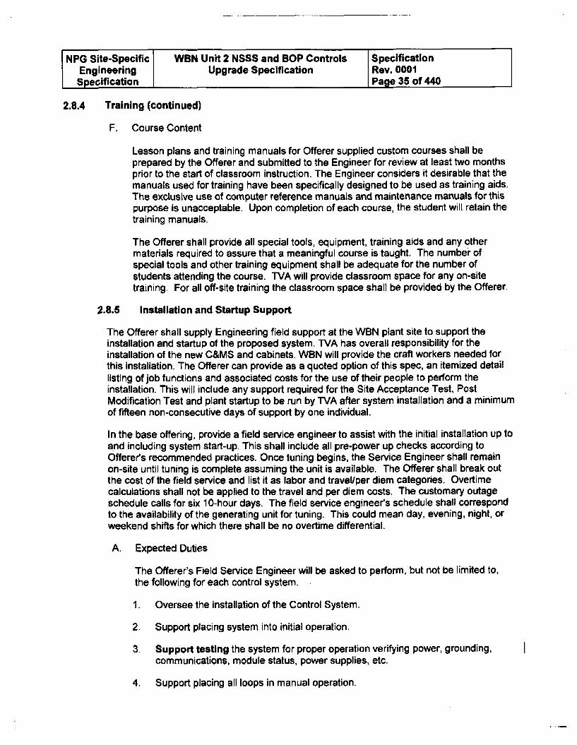
NPG Site-Specific WBN Unit 2 NSSS and SOP Controls SpecificationEngineering Upgrade Specification Rev. 0001Specification Page 35 of 440
2.8.4 Training (continued)
F. Course Content
Lesson plans and training manuals for Offerer supplied custom courses shall beprepared by the Offerer and submitted to the Engineer for review at least two monthsprior to the start of classroom instruction. The Engineer considers it desirable that themanuals used for training have been specifically designed to be used as training aids.The exclusive use of computer reference manuals and maintenance manuals for thispurpose is unacceptable. Upon completion of each course, the student will retain thetraining manuals.
The Offerer shall provide all special tools, equipment, training aids and any othermaterials required to assure that a meaningful course is taught. The number ofspecial tools and other training equipment shall be adequate for the number ofstudents attending the course. TVA will provide classroom space for any on-sitetraining. For all off-site training the classroom space shall be provided by the Offerer.
2.8.5 Installation and Startup Support
The Offerer shall supply Engineering field support at the WBN plant site to support theinstallation and startup of the proposed system. TVA has overall responsibility for theinstallation of the new C&MS and cabinets. WBN will provide the craft workers needed forthis installation. The Offerer can provide as a quoted option of this spec, an itemized detaillisting of job functions and associated costs for the use of their people to perform theinstallation. This will include any support required for the Site Acceptance Test, PostModification Test and plant startup to be run by TVA after system installation and a minimumof fifteen non-consecutive days of support by one individual.
In the base offering, provide a field service engineer to assist with the initial installation up toand including system start-up. This shall include all pre-power up checks according toOfferers recommended practices. Once tuning begins, the Service Engineer shall remainon-site until tuning is complete assuming the unit is available. The Offerer shall break outthe cost of the field service and list it as labor and travel/per diem categories. Overtimecalculations shall not be applied to the travel and per diem costs. The customary outageschedule calls for six 10-hour days. The field service engineer's schedule shall correspondto the availability of the generating unit for tuning. This could mean day, evening, night, orweekend shifts for which there shall be no overtime differential.
A. Expected Duties
The Offerer's Field Service Engineer will be asked to perform, but not be limited to,the following for each control system.
1. Oversee the installation of the Control System.
2. Support placing system into initial operation.
3. Support testing the system for proper operation verifying power, grounding,communications, module status, power supplies, etc.
4. Support placing all loops in manual operation.
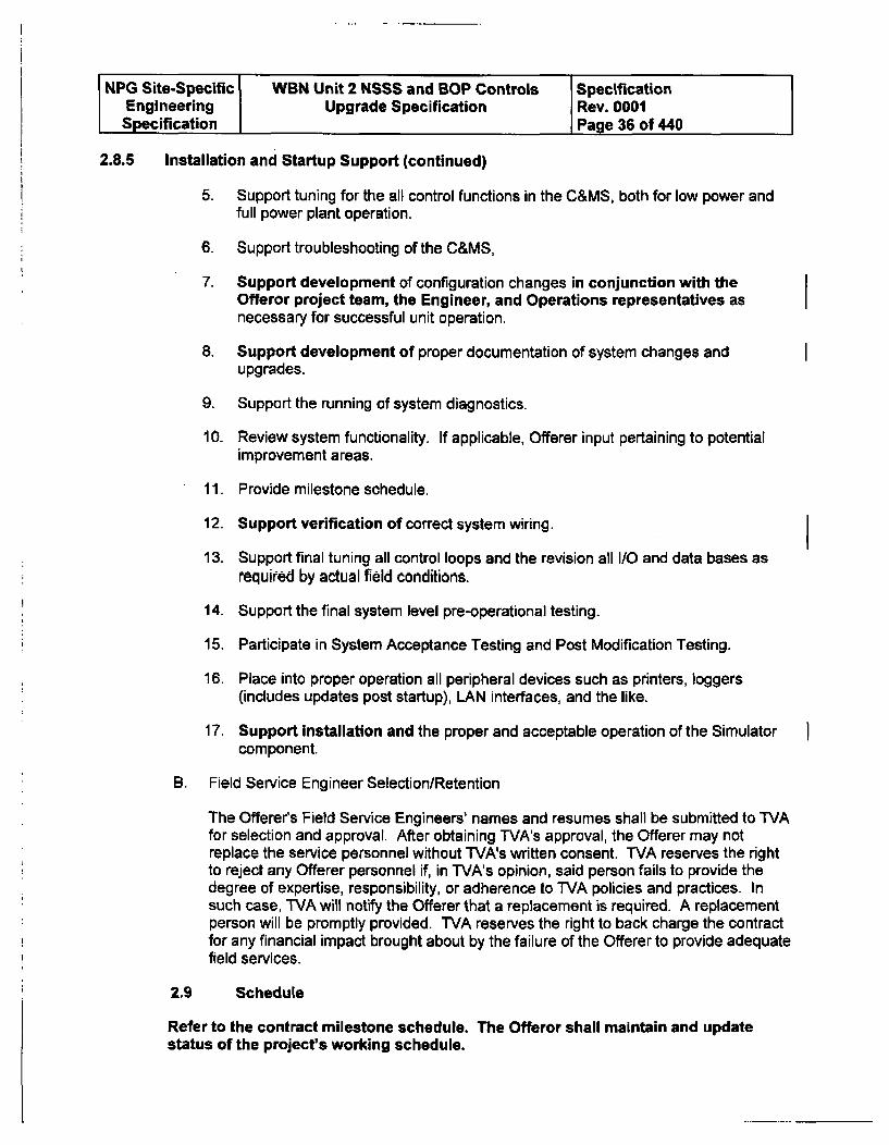
NPG Site-Specific WBN Unit 2 NSSS and BOP Controls SpecificationEngineering Upgrade Specification Rev. 0001Specification Page 36 of 440
2.8.5 Installation and Startup Support (continued)
5. Support tuning for the all control functions in the C&MS, both for low power andfull power plant operation.
6. Support troubleshooting of the C&MS,
7. Support development of configuration changes in conjunction with theOfferor project team, the Engineer, and Operations representatives asnecessary for successful unit operation.
8. Support development of proper documentation of system changes andupgrades.
9. Support the running of system diagnostics.
10. Review system functionality. If applicable, Offerer input pertaining to potentialimprovement areas.
11. Provide milestone schedule.
12. Support verification of correct system wiring.
13. Support final tuning all control loops and the revision all I/O and data bases asrequired by actual field conditions.
14. Support the final system level pre-operational testing.
15. Participate in System Acceptance Testing and Post Modification Testing.
16. Place into proper operation all peripheral devices such as printers, loggers(includes updates post startup), LAN interfaces, and the like.
17. Support installation and the proper and acceptable operation of the Simulatorcomponent.
B. Field Service Engineer Selection/Retention
The Offerer's Field Service Engineers' names and resumes shall be submitted to TVAfor selection and approval. After obtaining TVA's approval, the Offerer may notreplace the service personnel without TVA's written consent. TVA reserves the rightto reject any Offerer personnel if, in TVA's opinion, said person fails to provide thedegree of expertise, responsibility, or adherence to TVA policies and practices. Insuch case, TVA will notify the Offerer that a replacement is required. A replacementperson will be promptly provided. TVA reserves the right to back charge the contractfor any financial impact brought about by the failure of the Offerer to provide adequatefield services.
2.9 Schedule
Refer to the contract milestone schedule. The Offeror shall maintain and updatestatus of the project's working schedule.
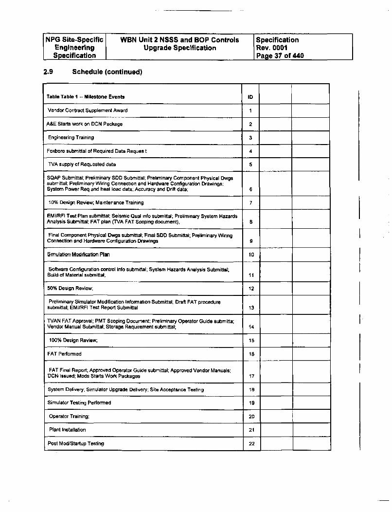
NPG Site-Specific WBN Unit 2 NSSS and BOP Controls SpecificationEngineering Upgrade Specification Rev. 0001Specification Page 37 of 440
2.9 Schedule (continued)
Table Table I -- Milestone Events ID
Vendor Contract Supplement Award 1
A&E Starts work on DCN Package 2
Engineering Training 3
Foxboro submittal of Required Data Reques t 4
TVA supply of Requested data 5
SOAP Submittal; Preliminary SDD Submittal; Preliminary Component Physical Dwgssubmittal; Preliminary Wiring Connection and Hardware Configuration Drawings;System Power Req and heat load data; Accuracy and Drift data; 6
10% Design Review, Maintenance Training 7
EMI/RFI Test Plan submittal; Seismic Qual info submittal;, Preliminary System HazardsAnalysis Submittal: FAT plan (TVA FAT Scoping document); 8
Final Component Physical Dwgs submittal; Final SDD Submittal; Preliminary WinngConnection and Hardware Configuration Drawings 9
8imulation MWdification Plan 10
Software Configuration control info submittal; System Hazards Analysis Submitlal;Build of Material submittal; 11
50% Design Review; 12
Preliminary Simulator Modification Information Submittal-, Draft FAT proceduresubmittal; EM[/RFI Test Report Submittal 13
"[VAN FAT Approval; PMT Scoping Document; Preliminary Operator Guide subm itta;
Vendor Manual Submittale; Storage Requirement submittal; 14
100% Design Review; 15
FAT Performed IS
FAT Final Report; Approved Operator Guide submittal; Approved Vendor Manuals;
DCN Issued; Mods Starts Work Packages 17
System Delivery; Simulator Upgrade Delivery; Site Acceptance Testing 18
Simulator Testing Performed 19
Operator Training; 20
Plant Installation 21
Post Mod/Startup Testing 22
NPG Site-Specific i WBN Unit 2 NSSS and SOP Controls SpecificationEngineering Upgrade Specification Rev. 0001Specification Page 38 of 440
3.0 GENERAL CONTROL SYSTEM REQUIREMENTS
3.1 Overview
3.1.1 Foxboro, GEMAC, and Robertshaw Control RacksUpgrade, and Turbine Building BOP Expansion Racks
This upgrade replaces most of the existing NSSS control system equipment, BOPGEMAC and Robertshaw equipment located in the Auxiliary Instrument Room (AIR)and the Main Control Room (MCR). Also, the C&MS shall supply new racks andhardware for interface with process equipment located in the Turbine Building(TBBOP).
3.1.2 Existing Specific Groupings
NSSS Groupings
Group 1 will consist of Racks 14, 15, and 16 with the main AC source supplied fromVital Inverter I
Group 2 will consist of Racks 17, 18, and 19 with the main AC source supplied fromVital Inverter II
Group 3 Will consist of Racks 20 and 21 with the main AC source supplied from VitalInverter Ill
Group 4 will consist of Racks 22, 23, 24, and 25 with the main AC source suppliedfrom Vital Inverter IV
Racks 26 and 27 - ICS Interface Racks
GEMAC and Robertshaw Racks
2-R-121 GEMAC Rack powered from Vital Inverter II
2-R-122 GEMAC Rack powered from Vital Inverter II
2-R-123 through 2-R-126 is a four bay GEMAC rack with all field cables terminated in2-R-126 and powered from Vital Inverter I
2-R-130 GEMAC Rack powered from Vital Inverter II
2-R-137 Robertshaw Rack powered from Vital Inverter I
2-R-141 Robertshaw Rack powered from powered from Vital Inverter I
2-R-1 42 Robertshaw Rack powered from Vital Inverter I
Power feeds for the new TBBOP Racks will be established later as designrequirements dictate.
NPG Site-Specific WBN Unit 2 NSSS and BOP Controls SpecificationEngineering Upgrade Specification Rev. 0001Specification Page 39 of 440
3.2 Hardware Requirements
3.2.1 Hardware Requirements for the Control System
A. System Safety Classification
This C&MS is classified as Quality Related (OR), IEEE Class Non-1 E, SeismicCategory 1L(B) (position retention) with the exception of equipment located inthe Turbine Building. The Turbine Building equipment is classified as Non-quality related (NOR), non-seismic.
B. Control System Architecture
The proposed system shall have the capability for distributed architecturecomprised of a family of independent functional processors. Redundant controlprocessor pairs will be located in individual racks to meet all the performancerequirements of this specification which includes areas such as response timerequirements, failure modes requirements, control system segmentationrequirements, etc. The Offerer shall determine the number and location for thepurpose providing a bid and shall submit this detail as part of the bid proposal.The functional processors shall have a configurable module/block basedprogram to execute specific dedicated tasks. Systems that require a centralizedcomputer for normal operation are not acceptable (i.e., a personal computer ormainframe computer). The controlling application shall be running in the localcontrol processors. Network switches shall not be used to process criticalcontrol system I/O.
The control system architecture shall be fault tolerant consisting of a minimum oftwo redundant channels consisting of microprocessor based controllers andmultiple I/O interface modules with remote mount capability. The control systemshall be linked together by a network of redundant digital communication pathsto form a completely integrated, distributed process control system. The systemwill interface with equipment located on the main control board, process controlracks, plant Annunciator Systems, the plant's Integrated Computer System(ICS), the operator's ODU based console displays, and an engineeringworkstation.
In order to perform its control function, the system shall also be responsible forreceiving, conditioning, and automatically selecting valid process measurementsignals and providing the necessary interlocks and alarms.
NPG Site-Specific WBN Unit 2 NSSS and BOP Controls SpecificationEngineering Upgrade Specification Rev. 0001Specification Page 40 of 440
3.2.1 Hardware Requirements for the Control System (continued)
C. Micro-processor Controller
The controller modules shall contain the process system's control strategies andsupport needs (e.g., alarms) which will be defined as the controller'sconfiguration. This configuration shall be composed of standard library functionsconnected together to provide the defined control strategies. Both the standardlibrary functions and the specific user configuration shall be stored in nonvolatilememory. The software of the library functions shall be validated by the Offererthrough design review, testing, and actual operation experience and shall be incompliance with Reference 3.15B. Appendix C is a listing of the requiredminimum library functions. In addition, the modules shall provide userprogrammable capabilities to allow the development of sophisticated,customized control strategies. All components shall be hot swappable andcapable of online reconfiguration without interrupting the operating controlsystem. Hot swappable means to change out the controller without affecting theautomatic control functions.
D. Redundancy
The control system shall be organized using a redundancy design which iselectrically isolated from each other such that a failure of one component will notresult in the loss of control capability of C&MS. A hardware failure (ie., electricalshort) or software problem in any module will not affect proper operation of theredundant channel. The system shall allow for the replacement of faultymodules online. Upon the subsequent power up of the replaced module, it shallbe capable of detecting the redundant controller already having control, beingreconfigured either automatically or manually and shall assume the role ofbackup controller.
1. Controllers
The C&MS shall be designed with a minimum of a primary and backupdigital controls consisting of redundant, distributed microprocessor basedsystems operating in parallel such that a failure of the primary controller willresult in the automatic transfer of control to its corresponding backupcontroller. Uninterrupted automatic control capability for plant operation ismandatory; therefore, the automatic transfer of control between a failed andthe good backup controller shall be fault tolerant and unrecognizable to thecontrolled devices. See Section 3.2.2H for definition. If the Offerer'sdefinition is different, they shall define their definition of Fault Tolerant. For aredundant control system, only one controller will be allowed control at anygiven time. Triple redundant systems are also acceptable and shall be faulttolerant with 100% coverage. The loss of any controller shall be alarmed.
NPG Site-Specific WBN Unit 2 NSSS and BOP Controls SpecificationEngineering Upgrade Specification Rev. 0001Specification Page 41 of 440
3.2.1 Hardware Requirements for the Control System (continued)
2. Inputs
Where specified, redundant input signals shall interface with the controlsystem using independent input module/cards (such as separate input cardfor each redundant input) so that a loss of an input module would result inthe loss of only one input signal. Redundant input modules can also beused to meet this requirement. Since the input module/card will containmultiple inputs, the complete loss of a single module/card shall not affectthe controlled process. These requirements shall be analyzed in the FMEAand tested in the FAT. TVA has initially identified the inputs requiringredundancy in the specific control system sections. The hazards analysis(system FMEA) and system functional requirements (Sections 4through 12 below) shalt identify any additional inputs that are critical.
3. Outputs
All critical control system outputs shall have redundant output module/cardsso that the loss of a single output module/card would not result in the loss ofautomatic control and would not create a process upset transient. Theredundant pair will connect to a single signal cable going to the final controldevice. These requirements shall be tested in the FAT. Upon loss of bothredundant processors, the output shall maintain the last good value toprevent a plant transient (see Section 3.2.2G.2.b). Note: For the MFPTinterface (10 to 50 ma outputs), the final output selector shall be a passivediode based circuit design.
4. Control Network
Internal communications between the redundant control system and alsobetween the system and certain peripherals (operator's LCDs, engineeringworkstation, and ICS) shall occur over redundant digital control networks.Isolation between the networks shall prevent failure in one side fromaffecting the alternate side. The loss of either network side shall bealarmed. The control network should be capable of transmitting processsignals to be used for process control and to support generation ofvalidation signals to eliminate single input signal failure from causingprocess perturbations. The control network shall be robust enough tocarry worst case data transmission, in the presence of a single failure upto and including the loss of one of the two redundant sides of thenetwork.
NPG Site-Specific WBN Unit 2 NSSS and BOP Controls SpecificationEngineering Upgrade Specification Rev. 0001Specification Page 42 of 440
3.2.1 Hardware Requirements for the Control System (continued)
5. ICS Interface
For communications interfacing to ICS, TVA defined interfaces shall beutilized. The interface should provide buffered digital to digitalcommunication with the plant computer. The C&MS shall provide digitalinterface with TVA ICS for all process inputs and output values,intermediate calculated values, and the status of logic parameters.
E. Physical Layout of Control System
The proposed locations of the racks being added is depicted in Figure 1 and 2.The Offerer shall be responsible for performing a walkdown of the AIR andMCR, obtaining measurements, and proposing a design that will fit within thedefined areas. Future addition of expansion cabinets shall be considered.
The MCR Remote I/O proposed location is to be mounted in a panel in the MainHorseshoe or external panel such as 2-M-1 1 (see Figure 2). WVA shall performwalkdown to determine final location.
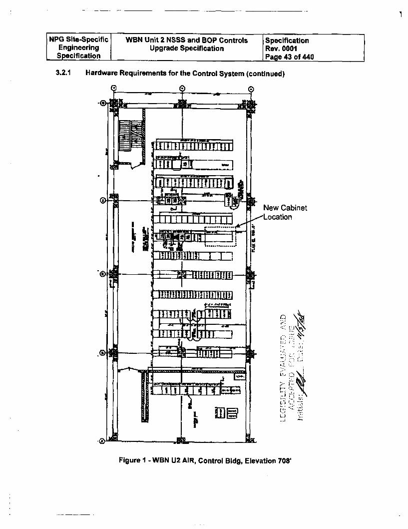
NPG Site-Specific WBN Unit 2 NSSS and BOP Controls SpecificationEngineering Upgrade Specification Rev. 0001Specification Page 43 of 440
3.2.1 Hardware Requirements for the Control System (continued)
New Cabinet
-..
Figure I - WBN U2 AIR, Control Bldg, Elevation 708'
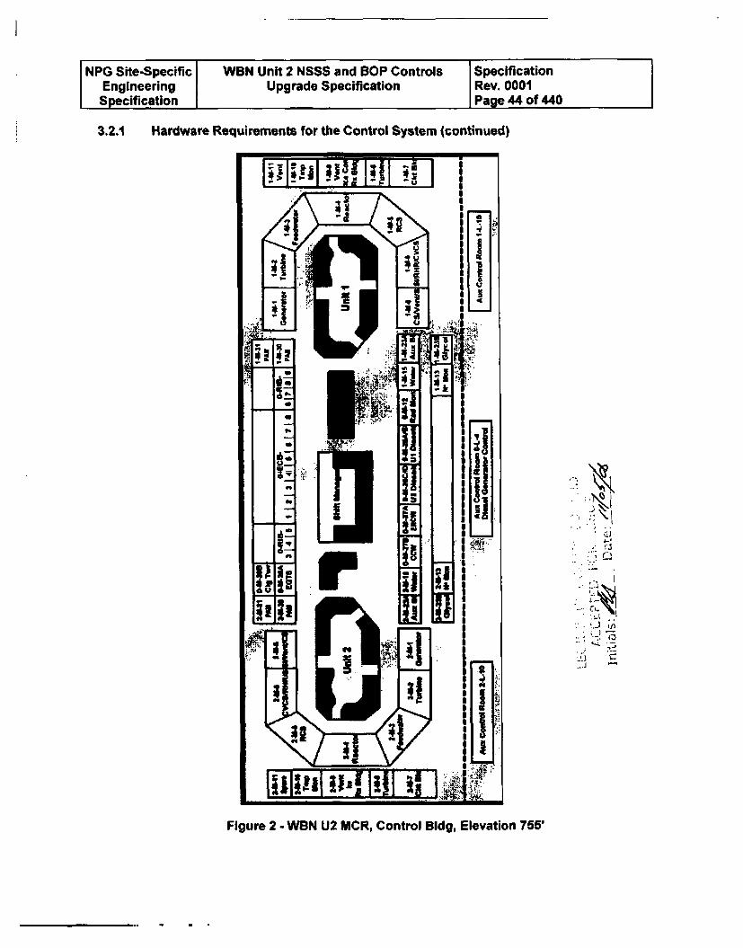
NPG Site-Specific WBN Unit 2 NSSS and BOP Controls SpecificationEngineering Upgrade Specification Rev. 0001Specification Page 44 of 440
3.2.1 Hardware Requirements for the Control System (continued)
ý.3
7zA
Figure 2 - WBN U2 MCR, Control Bldg, Elevation 755'
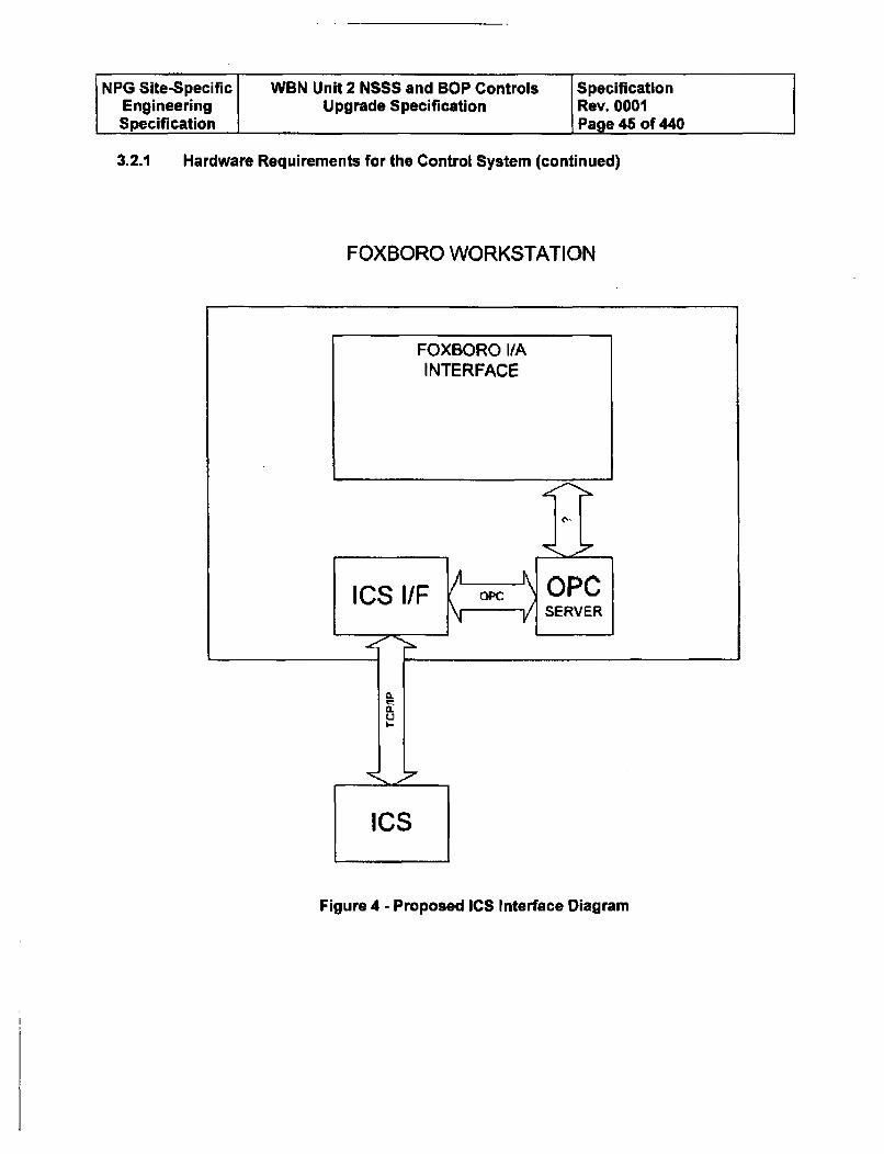
NPG Site-Specific WBN Unit 2 NSSS and BOP Controls SpecificationEngineering Upgrade Specification Rev. 0001Specification Page 45 of 440
3.2.1 Hardware Requirements for the Control System (continued)
FOXBORO WORKSTATION
Figure 4 - Proposed ICS Interface Diagram
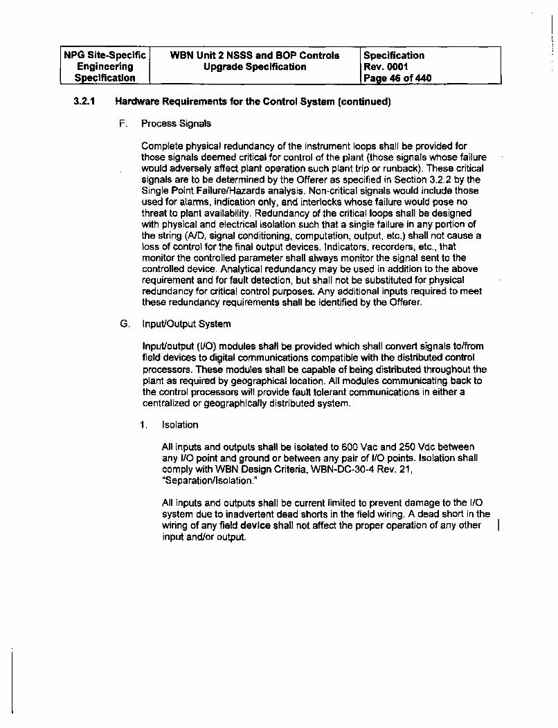
NPG Site-Specific WBN Unit 2 NSSS and BOP Controls SpecificationEngineering Upgrade Specification Rev. 0001Specification Page 40 of 440
3.2.1 Hardware Requirements for the Control System (continued)
F. Process Signals
Complete physical redundancy of the instrument loops shall be provided forthose signals deemed critical for control of the plant (those signals whose failurewould adversely affect plant operation such plant trip or runback). These criticalsignals are to be determined by the Offerer as specified in Section 3.2.2 by theSingle Point Failure/Hazards analysis. Non-critical signals would include thoseused for alarms, indication only, and interlocks whose failure would pose nothreat to plant availability. Redundancy of the critical loops shall be designedwith physical and electrical isolation such that a single failure in any portion ofthe string (A/D, signal conditioning, computation, output, etc.) shall not cause aloss of control for the final output devices. Indicators, recorders, etc., thatmonitor the controlled parameter shall always monitor the signal sent to thecontrolled device. Analytical redundancy may be used in addition to the aboverequirement and for fault detection, but shall not be substituted for physicalredundancy for critical control purposes. Any additional inputs required to meetthese redundancy requirements shall be identified by the Offerer.
G. Input/Output System
Input/output (I/O) modules shall be provided which shall convert signals to/fromfield devices to digital communications compatible with the distributed controlprocessors. These modules shall be capable of being distributed throughout theplant as required by geographical location. All modules communicating back tothe control processors will provide fault tolerant communications in either acentralized or geographically distributed system.
1. Isolation
All inputs and outputs shall be isolated to 600 Vac and 250 Vdc betweenany I/O point and ground or between any pair of I/O points. Isolation shallcomply with WBN Design Criteria, WBN-DC-30-4 Rev. 21,"Separation/Isolation."
All inputs and outputs shall be current limited to prevent damage to the I/Osystem due to inadvertent dead shorts in the field wiring. A dead short in thewiring of any field device shall not affect the proper operation of any otherinput and/or output.
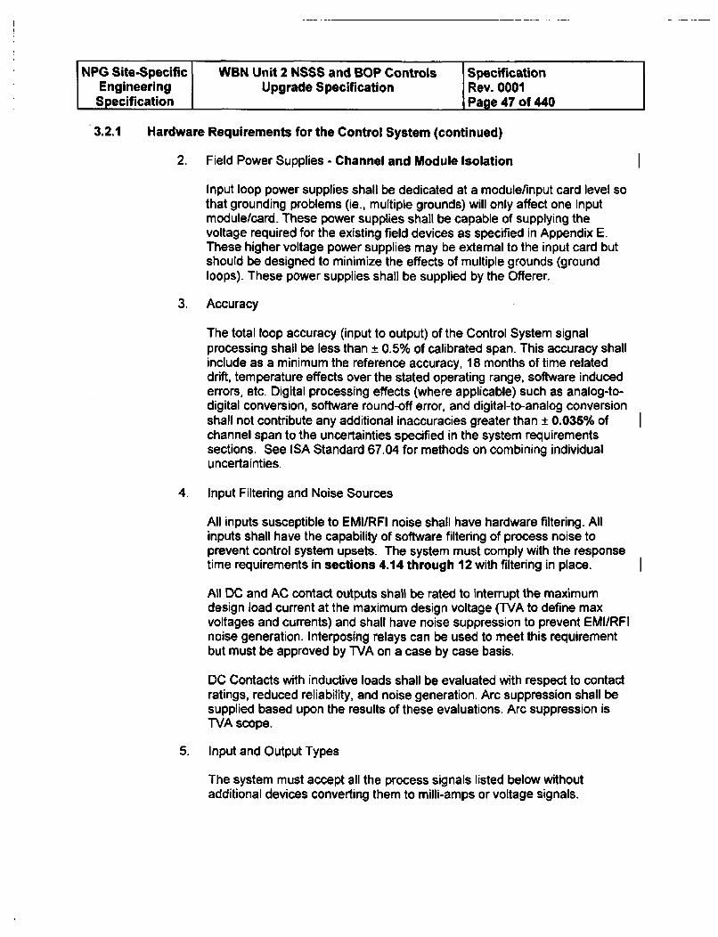
NPG Site-Specific WBN Unit 2 NSSS and BOP Controls SpecificationEngineering Upgrade Specification Rev. 0001Specification 1 Page 47 of 440
3.2.1 Hardware Requirements for the Control System (continued)
2. Field Power Supplies - Channel and Module Isolation
Input loop power supplies shall be dedicated at a module/input card level sothat grounding problems (ie., multiple grounds) will only affect one inputmodule/card. These power supplies shall be capable of supplying thevoltage required for the existing field devices as specified in Appendix E.These higher voltage power supplies may be external to the input card butshould be designed to minimize the effects of multiple grounds (groundloops). These power supplies shall be supplied by the Offerer.
3. Accuracy
The total loop accuracy (input to output) of the Control System signalprocessing shall be less than ± 0.5% of calibrated span. This accuracy shallinclude as a minimum the reference accuracy, 18 months of time relateddrift, temperature effects over the stated operating range, software inducederrors, etc. Digital processing effects (where applicable) such as analog-to-digital conversion, software round-off error, and digital-to-analog conversionshall not contribute any additional inaccuracies greater than ± 0.036% ofchannel span to the uncertainties specified in the system requirementssections. See ISA Standard 67.04 for methods on combining individualuncertainties.
4. Input Filtering and Noise Sources
All inputs susceptible to EMII/RFI noise shall have hardware filtering. Allinputs shall have the capability of software filtering of process noise toprevent control system upsets. The system must comply with the responsetime requirements in sections 4.14 through 12 with filtering in place.
All DC and AC contact outputs shall be rated to interrupt the maximumdesign load current at the maximum design voltage (TVA to define maxvoltages and currents) and shall have noise suppression to prevent EMI/RF1noise generation. Interposing relays can be used to meet this requirementbut must be approved by TVA on a case by case basis.
DC Contacts with inductive loads shall be evaluated with respect to contactratings, reduced reliability, and noise generation. Arc suppression shall besupplied based upon the results of these evaluations. Arc suppression isTVA scope.
5. Input and Output Types
The system must accept all the process signals listed below withoutadditional devices converting them to milli-amps or voltage signals.
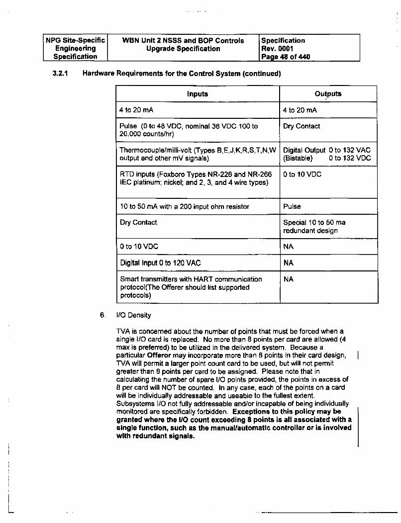
NPG Site-Specific WBN Unit 2 NSSS and BOP Controls SpecificationEngineering Upgrade Specification Rev. 0001Specification Page 48 of 440
3.2.1 Hardware Requirements for the Control System (continued)
Inputs Outputs
4 to 20 mA 4 to 20 mA
Pulse (0 to 48 VDC, nominal 36 VDC 100 to Dry Contact20,000 counts/hr)
Thermocouple/milli-volt (Types B,E,J,K,R,S,T,N,W Digital Output 0 to 132 VACoutput and other mV signals) (Bistable) 0 to 132 VDO
RTD inputs (Foxboro Types NR-226 and NR-266 0 to 10 VDCIEC platinum: nickel; and 2, 3, and 4 wire types)
10 to 50 mA with a 200 input ohm resistor Pulse
Dry Contact Special 10 to 50 ma
redundant design
0 to 10 VDC NA
Digital Input 0 to 120 VAC NA
Smart transmitters with HART communication NAprotocol(The Offerer should list supportedprotocols)
6. I/O Density
TVA is concerned about the number of points that must be forced when asingle I/O card is replaced. No more than 8 points per card are allowed (4max is preferred) to be utilized in the delivered system. Because aparticular Offeror may incorporate more than 8 points in their card design,WVA will permit a larger point count card to be used, but will not permitgreater than 8 points per card to be assigned. Please note that incalculating the number of spare I/O points provided, the points in excess of8 per card will NOT be counted. In any case, each of the points on a cardwill be individually addressable and useable to the fullest extent.Subsystems I/O not fully addressable and/or incapable of being individuallymonitored are specifically forbidden. Exceptions to this policy may begranted where the 110 count exceeding 8 points is all associated with asingle function, such as the manuallautomatlc controller or is involvedwith redundant signals.
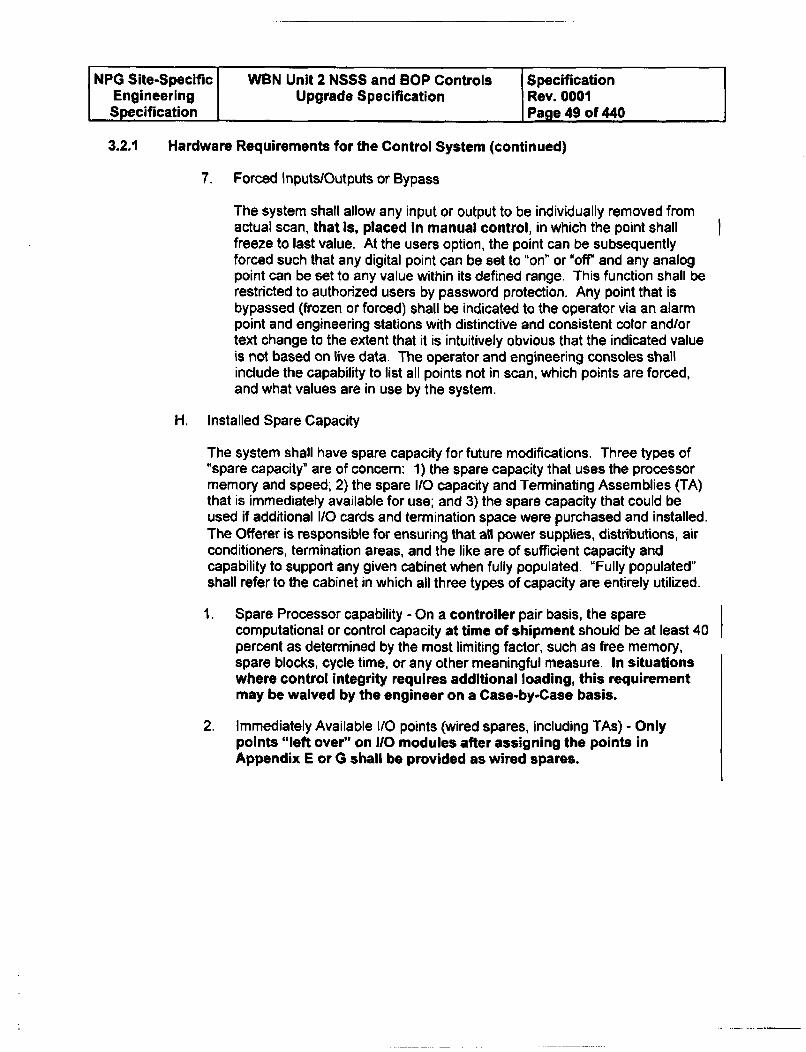
NPG Site-Specific WBN Unit 2 NSSS and BOP Controls SpecificationEngineering Upgrade Specification Rev. 0001Specification Page 49 of 440
3.2.1 Hardware Requirements for the Control System (continued)
7. Forced Inputs/Outputs or Bypass
The system shall allow any input or output to be individually removed fromactual scan, that is, placed In manual control, in which the point shallfreeze to last value. At the users option, the point can be subsequentlyforced such that any digital point can be set to "on" or 'off" and any analogpoint can be set to any value within its defined range. This function shall berestricted to authorized users by password protection. Any point that isbypassed (frozen or forced) shall be indicated to the operator via an alarmpoint and engineering stations with distinctive and consistent color and/ortext change to the extent that it is intuitively obvious that the indicated valueis not based on live data. The operator and engineering consoles shallinclude the capability to list all points not in scan, which points are forced,and what values are in use by the system.
H. Installed Spare Capacity
The system shall have spare capacity for future modifications. Three types of"spare capacity" are of concern: 1) the spare capacity that uses the processormemory and speed; 2) the spare 1(0 capacity and Terminating Assemblies (TA)that is immediately available for use; and 3) the spare capacity that could beused if additional I/O cards and termination space were purchased and installed.The Offerer is responsible for ensuring that all power supplies, distributions, airconditioners, termination areas, and the like are of sufficient capacity andcapability to support any given cabinet when fully populated. "Fully populated"shall refer to the cabinet in which all three types of capacity are entirely utilized.
1. Spare Processor capability - On a controller pair basis, the sparecomputational or control capacity at time of shipment should be at least 40percent as determined by the most limiting factor, such as free memory,spare blocks, cycle time, or any other meaningful measure. In situationswhere control integrity requires additional loading, this requirementmay be waived by the engineer on a Case-by-Case basis.
2. Immediately Available 110 points (wired spares, including TAs) - Onlypoints "left over" on 110 modules after assigning the points inAppendix E or G shall be provided as wired spares.
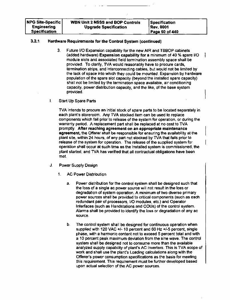
NPG Site-Specific WBN Unit 2 NSSS and BOP Controls SpecificationEngineering Upgrade Specification Rev. 0001Specification Page 50 of 440
3.2.1 Hardware Requirements for the Control System (continued)
3. Future 1/O Expansion capability for the new AIR and TBBOP cabinets(added hardware) Expansion capability for a minimum of 40 % spare I/Omodule slots and associated field termination assembly space shall beprovided. To clarify, TVA would reasonably have to procure cards,termination strips, and interconnecting cables, but would not be limited bythe lack of space into which they could be mounted. Expansion by hardwarepopulation of the spare slot capacity (beyond the installed spare capacity)shall not be limited by the termination space available, air conditioningcapacity, power distribution capacity, and the like, of the base systemprovided.
1. Start Up Spare Parts
TVA intends to procure an initial stock of spare parts to be located separately ineach plant's storeroom. Any TVA stocked item can be used to replacecomponents which fail prior to release of the system for operation, or during thewarranty period. A replacement part shall be replaced at no cost to WVApromptly. After reaching agreement on an appropriate maintenanceagreement, the Offerer shall be responsible for ensuring the availability at theplant site, within 24 hours, of any part not stocked by WVA that fails prior torelease of the system for operation, The release of the supplied system foroperation shall occur at such time as the installed system is commissioned, theplant started, and TVA has verified that all contractual obligations have beenmet.
J. Power Supply Design
1. AC Power Distribution
a. Power distribution for the control system shall be designed such thatthe loss of a single ac power source will not result in the loss ordegradation of system operation. A minimum of two diverse primarypower sources shall be provided to critical components (such as eachredundant pair of processors, I/O modules, etc.) and OperatorInterfaces (such as Handstations and ODUs) of the control system.Alarms shall be provided to identify the loss or degradation of any acsource.
b. The control system shall be designed for continuous operation whensupplied with 120 VAC +/- 10 percent and 60 Hz +/-5 percent, singlephase, with a harmonic content not to exceed 5 percent total and witha 10 percent peak maximum deviation from the sine wave. The controlsystem shall be designed not to consume more than the availableanalyzed supply capability of plant's AC inverters. This is TVA scope ofwork and shall use the plant's Loading calculations along with theOfferer's power consumption specifications as the basis for meetingthis requirement. This requirement must be further developed basedupon actual selection of the AC power sources.
NPG Site-Specific WBN Unit 2 NSSS and BOP Controls SpecificationEngineering Upgrade Specification Rev. 0001Specification Page 51 of 440
3.2.1 Hardware Requirements for the Control System (continued)
c. All AC loads shall be evaluated by the Offerer to ensure proper ridethrough capability (no effect on system or output loads) for a completeloss of one AC source.
d. Diverse AC power sources shall be provided to the redundantprocessor pair of the control system such that the loss of power fromany one source will not affect proper operation of the system. AllAC/DC loads from the system power bus to external loads shall befused and coordinated with upstream and downstream fuses/breakers.Any fuse assembly shall be an indicating type, capable of actuating analarm for remote annunciation of a blown fuse. The power distributionsystem shall be designed in such a manner that fuse and breakersizing is coordinated to ensure clearing of load side faults.
2. DC Power Distribution
a. The DC distribution system shall employ redundant DC power supplies(a minimum of two per processor pair) associated with each of the twodiverse AC power supply sources. Auctioneering of the supplies'outputs should be performed at the lowest level practicable (individualcard, module, nest, etc.). Fault protection and detection shall beprovided for the auctioneered DC power supplies. The failure of anypower supply shall be alarmed. Power supply status shall be indicatedon the power supply itself. The System design shall employ sufficientmeans to replace failed power supplies, while online, without affectingcontrol system's operation and shall be easily accessible.
b. If the loss of the power supply to any control system inputs, controlboard indicators, or manual/automatic stations results in a plant trip,runback, or entry into a Tech Spec Limiting Condition for Operation,the power supplies shall be redundant.
c. Auctioneering shall be performed utilizing a sharing process and theOfferer must be demonstrate that the redundant supply is capable ofcarrying the system load if the first supply fails.
d. A power supply failure in the high direction shall not result in thecomplete loss of power.
3. Loss and Restoration of Power
The control system shall be designed to meet the following requirements onthe loss and restoration of power:
a. Upon the loss of one DC redundant power supply, the control systemshall be capable of recognizing the failure, transferring power toprevent control system upset, and alarming both the loss of power andthe corrective action taken by the control system.
NPG Site-Specific WBN Unit 2 NSSS and BOP Controls SpecificationEngineering Upgrade Specification Rev. 0001Specification Page 52 of 440
3.2.1 Hardware Requirements for the Control System (continued)
b. Upon the loss of all AC and/or all DC power, the output signals shallfail to zero; position actuated equipment shall be designed byothers to fail to their defined design basis failure state.
c. Upon the loss of all power, the control system shall be designed sothat all indicators and recorders associated with that system are readilydetectable as in the failed state (ie., fail downscale).
d. Upon the restoration of power (AC, DC, or both), indication shall beprovided to the main control room to indicate the restoration of power.
e. Upon the restoration of power, the actuated equipment positions shallbe predictable and repeatable. Where identified in the systemfunctional requirements, power-up initialization control shall beexecuted to bring plant systems to a known state.
f. On restoration of power, the system shall be capable of restoringnormal operation without requiring a manual download of programfrom a central computer system (i.e. program must be stored within theCPU).
g. The Offerer shall be provided the momentary loss of AC power ride
through time.
4. Field Supplied Loads
For field supplied loads such as transmitters, the power supply arrangementshall meet the following requirements:
a. Each load shall be individually isolated such as transformer isolation
so that multiple grounds on fields will not affect the control system.
b. Uses differential input design to reduce the potential for noise.
c. Shall be capable of supplying voltages required for each field load.
K. Grounding Requirements
Each Rack enclosure shall have an electrical safety ground bus and an isolatedinstrument ground bus. A compression fitting suitable for connection to a 4/0AWG main plant grounding cable shall be provided in the appropriateenclosures. The Offerer shall provide all engineering and materials required toensure the adequacy of their cabinet ground system as it pertains to theinstalled system.
NPG Site-Specific WBN Unit 2 NSSS and BOP Controls SpecificationEngineering Upgrade Specification Rev. 0001Specification Page 53 of 440
3.2.1 Hardware Requirements for the Control System (continued)
All cables that are ground system related shall be clearly marked and shall begreen or green with trace color. For bare copper cables, a color sleeve shall beattached at each point of connection. Color coding for separate ground systemsshall be consistent and unique
L. Internal Rack Cabling Requirements
All cabling provided by the Offerer shall use documented cable and wiring goodpractices for internal panel wiring. These good wiring practices shouldencompass such issues as proper wire sizing associated with current loading;EMI/RFI protection by the use of shielding and proper termination, use of twistedpair wiring, enclosure protection, separation of noise generation circuit (relays),etc.; and proper termination as specified in this specification.
1. System Cabling
Interconnecting Control System rack cables, network cables, and the likeshall be supplied by the Offerer.
Prefabricated cables with multi-conductor cable connectors shall besupplied to connect the control logic cabinets with each peripheral or fieldtermination cabinet. The field end of any cable used shall be capable ofbeing cut and re-terminated during installation or pulled through existingplant conduit.
Where prefabricated cables are furnished by the Offerer, the cables shall beterminated with the use of Cannon plugs, or approved equal. Theconnectors (plug and receptacle) shall have rugged metal shells or bemanufactured of high-strength insulating material. When separate, the livepart shall be a female contact so that shorting of pins is not possible.Adequate cable strain-relief clamps shall be provided. There shall be noexposed live parts on the rear of the plug. An environmental seal ispreferred. The plug and receptacle design shall be such that electricalcontact cannot be established until the plug and receptacle are correctlyaligned.
2. Cabinet Wiring
All wiring shall be securely installed and neatly bundled with flame resistant,nonmetallic tie bands. All electrical connections shall be readily accessible.It shall be possible to inspect, remove, and add connections to any devicewithout removal of the device, mounting steel, piping, wire-ways, or tubing.Where wiring must cross sharp metal edges, adequate protection shall beprovided, preferably by Autolyze or by approved grommets. In addition,each device shall be removable without disturbing other devices, mountingsteel, etc.
NPG Site-Specific WBN Unit 2 NSSS and BOP Controls SpecificationEngineering Upgrade Specification Rev. 0001Specification Page 54 of 440
3.2.1 Hardware Requirements for the Control System (continued)
All terminal points shall be clearly and permanently labeled andconveniently located. All terminal points shall be clearly labeled inaccordance with the Offerer's wiring drawings, which shall contain physicallocation by cabinet, rack, terminal block, and terminal.
Offerer factory wiring shall all be terminated on the same side of theterminal block or column of terminal blocks. All electrical connectionsbetween cabinets shall be by Offerer supplied prefabricated cables. Prefabcable plugs shall be keyed.
The Offerer shall segregate by voltage level all terminal blocks for internalwiring and field cable connections. The Offerer shall make provisions forterminating and grounding individual shield and overall cable shield wiresfor all analog inputs. Provisions for powering of interposing relay coils shallbe the responsibility of the Offerer.
High density I/O termination panels or blocks are not acceptable. The intent
is to provide ease of installation and maintenance of the system.
3. Fiber Optic Media
All fiber optic cable used in Class I structures shall meet the requirements ofUL 910 and iF_2 383. This cable should also meet the requirements formultimode, tight buffered fiber optic cable suitable for broadbandtransmission of video, audio, and data signals and be suitable for indoor orunderground conduit installation in wet or dry locations.In addition, plasticfiber optic cable is not acceptable. Metallic or conductive coverings,strength members or fibers shall not be used.
M. Fusing
TVA shall ensure all fusing shall be coordinated with upstream and downstreamprotective devices. The Offerer shall provide a fuse list with manufacture andpart number. Output fuse protection shall be replaceable without affecting othercontrol outputs mounted on the same circuit card. i.e., fuses should bereplaceable without unplugging cards from the system.
3.2.2 Critical Control System Signals
A. Critical Control System Signal Definition
The definition of whether a control system is critical or non-critical is providedin the system functional requirements defined in Sections 4 through 12.
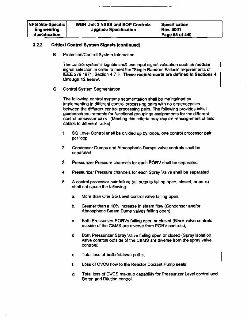
NPG Site-Specific WBN Unit 2 NSSS and BOP Controls SpecificationEngineering Upgrade Specification Rev. 0001Specification Page 55 of 440
3.2.2 Critical Control System Signals (continued)
B. Protection/Control System Interaction
The control system's signals shall use input signal validation such as mediansignal selection in order to meet the "Single Random Failure" requirements ofIEEE 279 1971, Section 4.7.3. These requirements are defined in Sections 4through 12 below.
C, Control System Segmentation
The following control systems segmentation shall be maintained byimplementing in different control processing pairs with no dependenciesbetween the different control processing pairs. The following provides initialguidance/requirements for functional groupings assignments for the differentcontrol processor pairs. (Meeting this criteria may require reassignment of fieldcables to different racks)
1. SG Level Control shall be divided up by loops, one control processor pairper loop.
2. Condenser Dumps and Atmospheric Dumps valve controls shall beseparated.
3. Pressurizer Pressure channels for each PORV shall be separated.
4. Pressurizer Pressure channels for each Spray Valve shall be separated
5. A control processor pair failure (all outputs failing open, closed, or as is)shall not cause the following:
a. More than One SG Level control valve failing open;
b. Greater than a 10% increase in steam flow (Condenser and/orAtmospheric Steam Dump valves failing open);
c. Both Pressurizer PORVs failing open or closed (Block valve controlsoutside of the C&MS are diverse from PORV controls);
d. Both Pressurizer Spray Valve failing open or closed (Spray isolationvalve controls outside of the C&MS are diverse from the spray valvecontrols);
e. Total loss of both letdown paths;-
f. Loss of CVCS flow to the Reactor Coolant Pump seals;
g. Total loss of CVCS makeup capability for Pressurizer Level control andBoron and Dilution control;
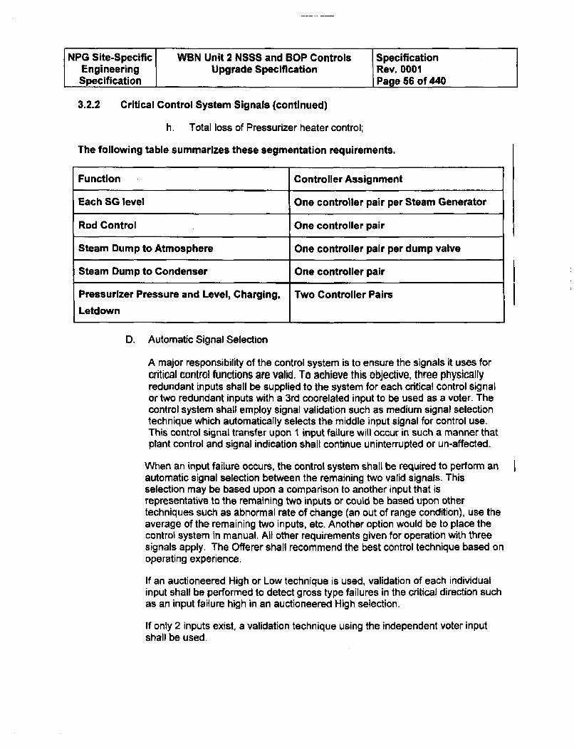
NPG Site-Specific WBN Unit 2 NSSS and BOP Controls SpecificationEngineering Upgrade Specification Rev. 0001Specification Page 56 of 440
3.2.2 Critical Control System Signals (continued)
h. Total loss of Pressurizer heater control;
The following table summarizes these segmentation requirements.
Function Controller Assignment
Each SG level One controller pair per Steam Generator
Rod Control One controller pair
Steam Dump to Atmosphere One controller pair per dump valve
Steam Dump to Condenser One controller pair
Pressurizer Pressure and Level, Charging, Two Controller Pairs
Letdown
D. Automatic Signal Selection
A major responsibility of the control system is to ensure the signals it uses forcritical control functions are valid. To achieve this objective, three physicallyredundant inputs shall be supplied to the system for each critical control signalor two redundant inputs with a 3rd coorelated input to be used as a voter. Thecontrol system shall employ signal validation such as medium signal selectiontechnique which automatically selects the middle input signal for control use.This control signal transfer upon 1 input failure will occur in such a manner thatplant control and signal indication shall continue uninterrupted or un-affected.
When an input failure occurs, the control system shall be required to perform anautomatic signal selection between the remaining two valid signals. Thisselection may be based upon a comparison to another input that isrepresentative to the remaining two inputs or could be based upon othertechniques such as abnormal rate of change (an out of range condition), use theaverage of the remaining two inputs, etc. Another option would be to place thecontrol system in manual. All other requirements given for operation with threesignals apply. The Offerer shall recommend the best control technique based onoperating experience.
If an auctioneered High or Low technique is used, validation of each individualinput shall be performed to detect gross type failures in the critical direction suchas an input failure high in an auctioneered High selection.
If only 2 inputs exist, a validation technique using the independent voter inputshall be used.
I
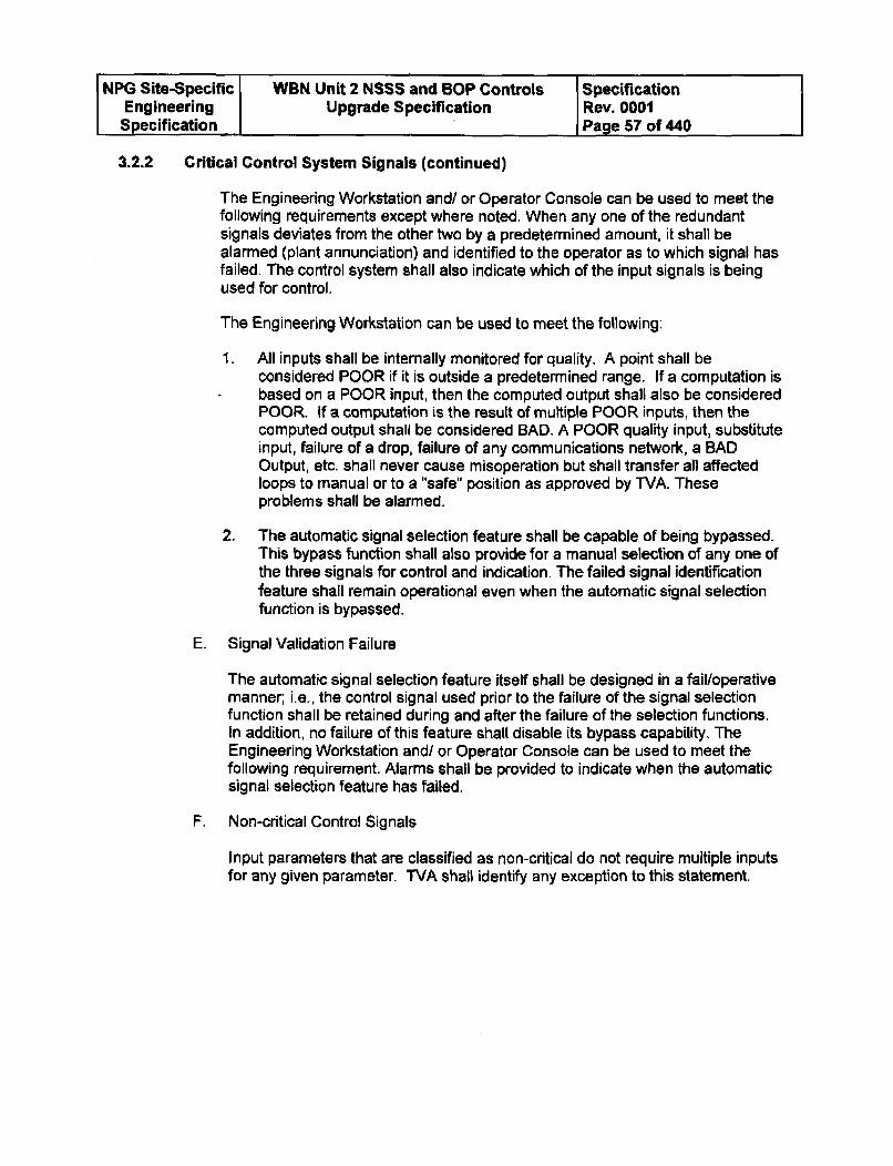
NPG Site-Specific WBN Unit 2 NSSS and BOP Controls SpecificationEngineering Upgrade Specification Rev. 0001Specification Page 57 of 440
3.2.2 Critical Control System Signals (continued)
The Engineering Workstation and/ or Operator Console can be used to meet thefollowing requirements except where noted, When any one of the redundantsignals deviates from the other two by a predetermined amount, it shall bealarmed (plant annunciation) and identified to the operator as to which signal hasfailed. The control system shall also indicate which of the input signals is beingused for control.
The Engineering Workstation can be used to meet the following:
1. All inputs shall be internally monitored for quality. A point shall beconsidered POOR if it is outside a predetermined range. If a computation is
- based on a POOR input, then the computed output shall also be consideredPOOR. If a computation is the result of multiple POOR inputs, then thecomputed output shall be considered BAD. A POOR quality input, substituteinput, failure of a drop, failure of any communications network, a BADOutput, etc. shall never cause misoperation but shall transfer all affectedloops to manual or to a "safe" position as approved by TVA. Theseproblems shall be alarmed.
2. The automatic signal selection feature shall be capable of being bypassed.This bypass function shall also provide for a manual selection of any one ofthe three signals for control and indication. The failed signal identificationfeature shall remain operational even when the automatic signal selectionfunction is bypassed.
E. Signal Validation Failure
The automatic signal selection feature itself shall be designed in a fail/operativemanner;, i.e., the control signal used prior to the failure of the signal selectionfunction shall be retained during and after the failure of the selection functions.In addition, no failure of this feature shall disable its bypass capability. TheEngineering Workstation and/ or Operator Console can be used to meet thefollowing requirement. Alarms shall be provided to indicate when the automaticsignal selection feature has failed.
F. Non-critical Control Signals
Input parameters that are classified as non-critical do not require multiple inputsfor any given parameter. TVA shahl identify any exception to this statement.
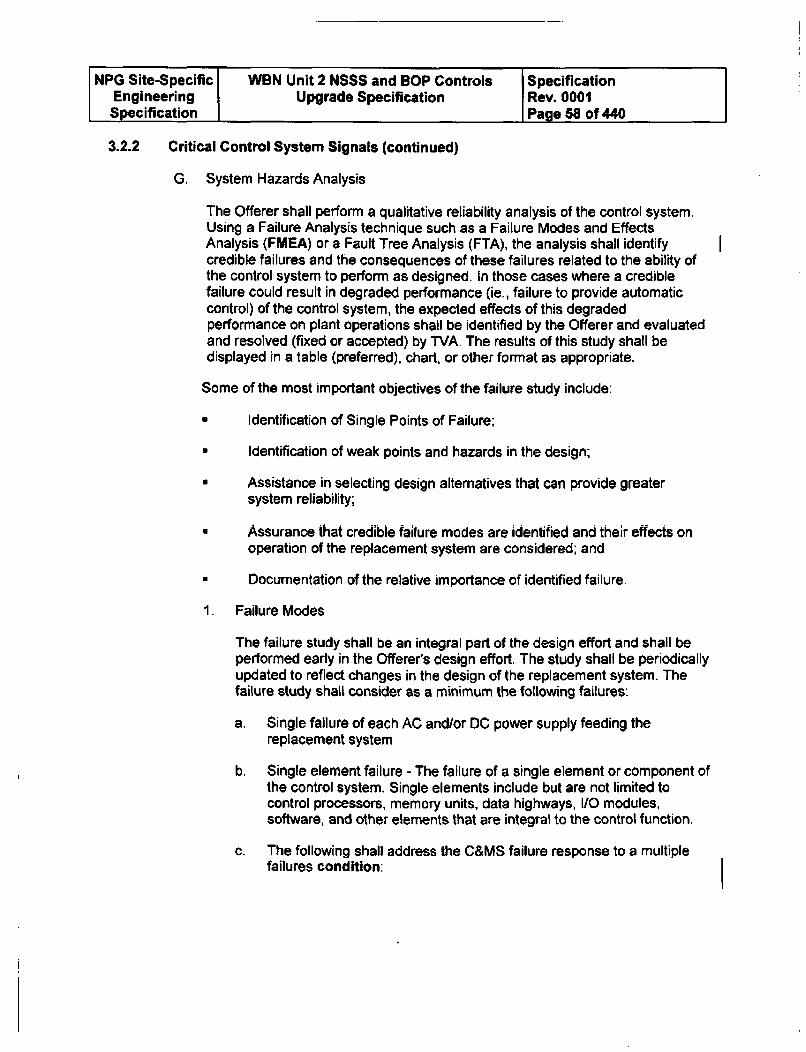
NPG Site-Specific WBN Unit 2 NSSS and BOP Controls SpecificationEngineering Upgrade Specification Rev. 0001Specification Page 58 of 440
3.2.2 Critical Control System Signals (continued)
G. System Hazards Analysis
The Offerer shall perform a qualitative reliability analysis of the control system.Using a Failure Analysis technique such as a Failure Modes and EffectsAnalysis (FMEA) or a Fault Tree Analysis (FTA), the analysis shall identifycredible failures and the consequences of these failures related to the ability ofthe control system to perform as designed. In those cases where a crediblefailure could result in degraded performance (ie., failure to provide automaticcontrol) of the control system, the expected effects of this degradedperformance on plant operations shall be identified by the Offerer and evaluatedand resolved (fixed or accepted) by TVA. The results of this study shall bedisplayed in a table (preferred), chart, or other format as appropriate.
Some of the most important objectives of the failure study include:
9 Identification of Single Points of Failure;
w Identification of weak points and hazards in the design;
N Assistance in selecting design alternatives that can provide greatersystem reliability;
a Assurance that credible failure modes are identified and their effects on
operation of the replacement system are considered; and
N Documentation of the relative importance of identified failure.
1. Failure Modes
The failure study shall be an integral part of the design effort and shall beperformed early in the Offerer's design effort. The study shall be periodicallyupdated to reflect changes in the design of the replacement system. Thefailure study shall consider as a minimum the following failures:
a. Single failure of each AC and/or DC power supply feeding thereplacement system
b. Single element failure - The failure of a single element or component ofthe control system. Single elements include but are not limited tocontrol processors, memory units, data highways, I/O modules,software, and other elements that are integral to the control function.
c. The following shall address the C&MS failure response to a multiplefailures condition:
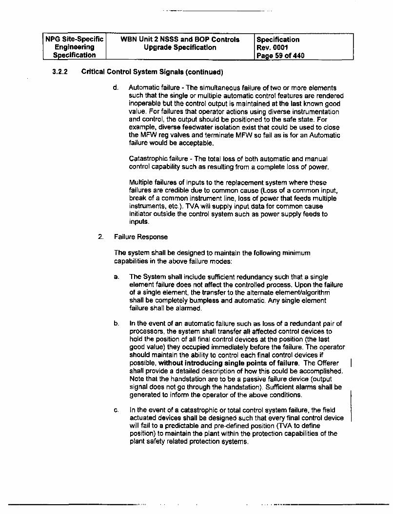
NPG Site-Specific WBN Unit 2 NSSS and BOP Controls SpecificationEngineering Upgrade Specification Rev. 0001Specification Page 59 of 440
3.2.2 Critical Control System Signals (continued)
d. Automatic failure - The simultaneous failure of two or more elementssuch that the single or multiple automatic control features are renderedinoperable but the control output is maintained at the last known goodvalue. For failures that operator actions using diverse instrumentationand control, the output should be positioned to the safe state. Forexample, diverse feedwater isolation exist that could be used to closethe MFW reg valves and terminate MFW so fail as is for an Automaticfailure would be acceptable.
Catastrophic failure - The total loss of both automatic and manualcontrol capability such as resulting from a complete loss of power.
Multiple failures of inputs to the replacement system where thesefailures are credible due to common cause (Loss of a common input,break of a common instrument line, loss of power that feeds multipleinstruments, etc.). TVA will supply input data for common causeinitiator outside the control system such as power supply feeds toinputs.
2. Failure Response
The system shall be designed to maintain the following minimumcapabilities in the above failure modes:
a. The System shall include sufficient redundancy such that a singleelement failure does not affect the controlled process. Upon the failureof a single element, the transfer to the alternate element/algorithmshall be completely bumpless and automatic. Any single elementfailure shall be alarmed.
b. In the event of an automatic failure such as loss of a redundant pair ofprocessors, the system shall transfer all affected control devices tohold the position of all final control devices at the position (the lastgood value) they occupied immediately before the failure. The operatorshould maintain the ability to control each final control devices ifpossible, without introducing single points of failure. The Offerershall provide a detailed description of how this could be accomplished.Note that the handstation are to be a passive failure device (outputsignal does not go through the handstation). Sufficient alarms shall begenerated to inform the operator of the above conditions.
c. In the event of a catastrophic or total control system failure, the fieldactuated devices shall be designed such that every final control devicewill fail to a predictable and pre-defined position (TVA to defineposition) to maintain the plant within the protection capabilities of theplant safety related protection systems.
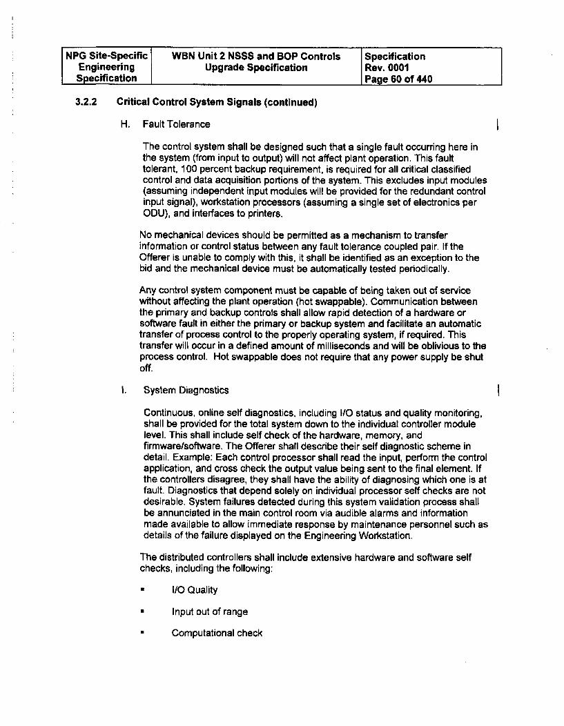
NPG Site-Specific WBN Unit 2 NSSS and BOP Controls SpecificationEngineering Upgrade Specification Rev. 0001Specification Page 60 of 440
3.2.2 Critical Control System Signals (continued)
H. Fault Tolerance
The control system shall be designed such that a single fault occurring here inthe system (from input to output) will not affect plant operation. This faulttolerant, 100 percent backup requirement, is required for all critical classifiedcontrol and data acquisition portions of the systemr This excludes input modules(assuming independent input modules will be provided for the redundant controlinput signal), workstation processors (assuming a single set of electronics perODU), and interfaces to printers.
No mechanical devices should be permitted as a mechanism to transferinformation or control status between any fault tolerance coupled pair. If theOfferer is unable to comply with this, it shall be identified as an exception to thebid and the mechanical device must be automatically tested periodically.
Any control system component must be capable of being taken out of servicewithout affecting the plant operation (hot swappable). Communication betweenthe primary and backup controls shall allow rapid detection of a hardware orsoftware fault in either the primary or backup system and facilitate an automatictransfer of process control to the properly operating system, if required. Thistransfer will occur in a defined amount of milliseconds and will be oblivious to theprocess control. Hot swappable does not require that any power supply be shutOff.
I. System Diagnostics
Continuous, online self diagnostics, including 1/0 status and quality monitoring,shall be provided for the total system down to the individual controller modulelevel. This shall include self check of the hardware, memory, andfirmware/software. The Offerer shall describe their self diagnostic scheme indetail. Example: Each control processor shall read the input, perform the controlapplication, and cross check the output value being sent to the final element. Ifthe controllers disagree, they shall have the ability of diagnosing which one is atfault. Diagnostics that depend solely on individual processor self checks are notdesirable. System failures detected during this system validation process shallbe annunciated in the main control room via audible alarms and informationmade available to allow immediate response by maintenance personnel such asdetails of the failure displayed on the Engineering Workstation.
The distributed controllers shall include extensive hardware and software self
checks, including the following:
I/O Quality
* Input out of range
• Computational check
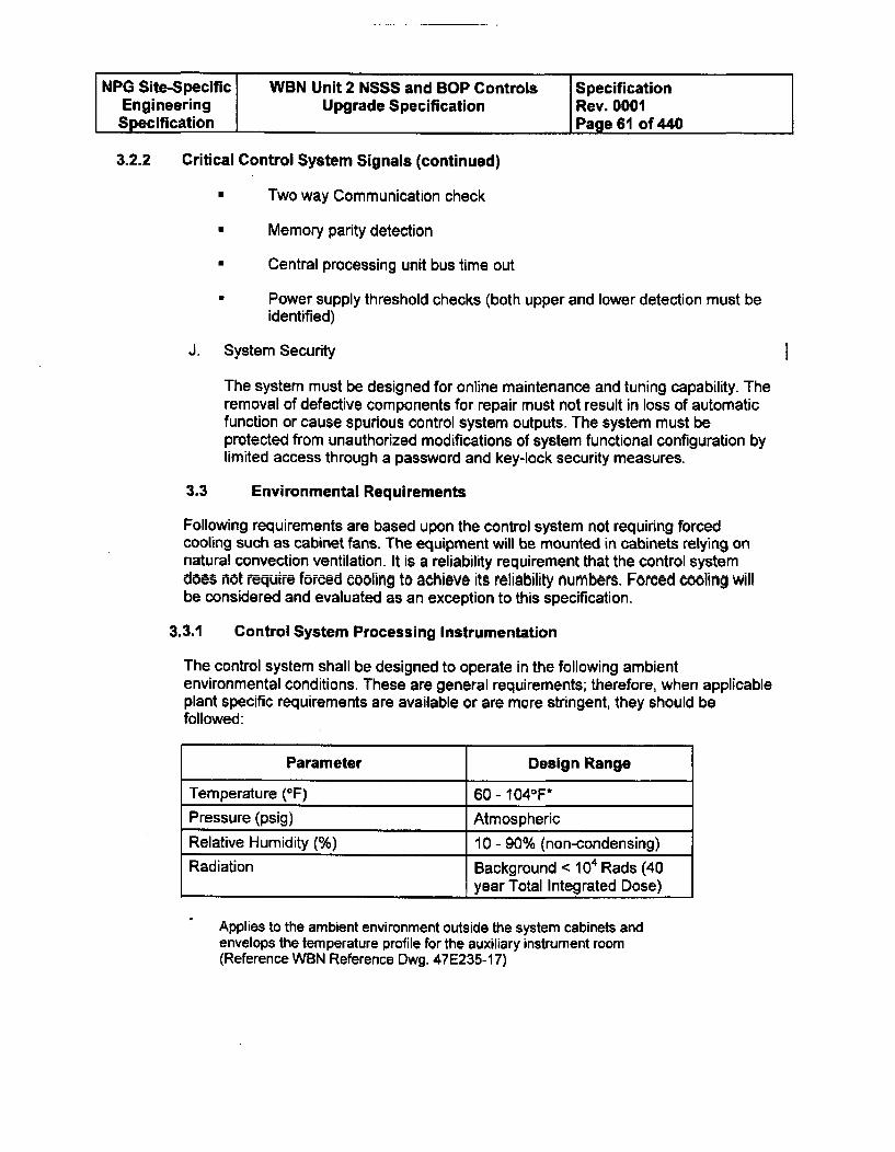
NPG Site-Specific WBN Unit 2 NSSS and BOP Controls SpecificationEngineering Upgrade Specification Rev. 0001Specification Page 61 of 440
3.2.2 Critical Control System Signals (continued)
0 Two way Communication check
v Memory parity detection
E Central processing unit bus time out
a Power supply threshold checks (both upper and lower detection must beidentified)
J. System Security
The system must be designed for online maintenance and tuning capability. Theremoval of defective components for repair must not result in loss of automaticfunction or cause spurious control system outputs. The system must beprotected from unauthorized modifications of system functional configuration bylimited access through a password and key-lock security measures.
3.3 Environmental Requirements
Following requirements are based upon the control system not requiring forcedcooling such as cabinet fans. The equipment will be mounted in cabinets relying onnatural convection ventilation. It is a reliability requirement that the control systemdoes not require forced cooling to achieve its reliability numbers. Forced cooling willbe considered and evaluated as an exception to this specification.
3.3.1 Control System Processing Instrumentation
The control system shall be designed to operate in the following ambientenvironmental conditions. These are general requirements; therefore, when applicableplant specific requirements are available or are more stringent, they should befollowed:
Parameter Design Range
Temperature (OF) 60 - 1040 F*Pressure (psig) Atmospheric
Relative Humidity (%) 10 - 90% (non-condensing)
Radiation Background < 104 Rads (40year Total Integrated Dose)
Applies to the ambient environment outside the system cabinets andenvelops the temperature profile for the auxiliary instrument room(Reference WBN Reference Dwg. 47E235-17)
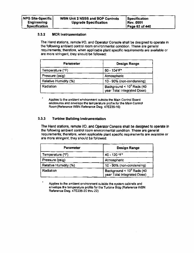
NPG Site-Specific WBN Unit 2 NSSS and BOP Controls SpecificationEngineering Upgrade Specification Rev. 0001Specification Page 62 of 440
3.3.2 MCR Instrumentation
The Hand stations, remote I/0, and Operator Console shall be designed to operate inthe following ambient control room environmental condition. These are generalrequirements; therefore, when applicable plant specific requirements are available orare more stringent, they should be followed:
Parameter Design Range
Temperature (OF) 60 - 1040F*
Pressure (psig) Atmospheric
Relative Humidity (%) 10 - 90% (non-condensing)
Radiation Background < 103 Rads (40year Total Integrated Dose)
Applies to the ambient environment outside the Main Control Boardenclosures and envelops the temperature profile for the Main ControlRoom(Reference WBN Reference Dwg. 47E235-16)
3.3.3 Turbine Building Instrumentation
The Hand stations, remote I/O, and Operator Console shall be designed to operate inthe following ambient control room environmental condition, These are generalrequirements; therefore, when applicable plant specific requirements are available orare more stringent, they should be followed:
Parameter Design Range
Temperature (OF) 40 - 120 OF*Pressure (psig) AtmosphericRelative Humidity (%) 10 - 90% (non-condensing)
Radiation Background < 103 Rads (40year Total Integrated Dose)
Applies to the ambient environment outside the system cabinets andenvelops the temperature profile for the Turbine Bldg (Reference WBNReference Dwg. 47E235-20 thru 22)
NPG Site-Specific WBN Unit 2 NSSS and BOP Controls SpecificationEngineering Upgrade Specification Rev. 0001Specification Page 63 of 440
3.4 Man Machine Interfaces
3.4.1 Control/Handstations
A manual control interface shall be provided for devices listed in Appendix F thatare controlled by the automatic control system to allow for operator control. Themanual system shall be sufficiently independent of the automatic system to precludeany single failure from rendering the automatic control system inoperable. Theautomatic system shall provide for a bumpless transfer from either manual toautomatic control or automatic to manual. This means that the system shall bedesigned such that any portion of the system can be transferred from automatic tomanual and from manual to automatic without any manual balancing and without anysystem disturbances (bumpless transfer). The method of bumpless transfer shall bedetermined on a loop by loop basis.
The operator interface shall be through both "hard" manual/automatic stations andthrough flat panel displays (described below) located on the main control board.The Stations shall allow positioning of the devices through the control system. Thestations shall be passive from a failure aspect. A failure of the station shall not affectthe automatic controls. The station's displays shall be capable of providing analogtype Indications with up to three variables displayed such as (1) Output demand; (2)Setpoint; and/or (3) Deviation. If the indication is digital, all parameters should beconfigurable with respect to specific input parameters and the parameters shall bedisplayed in engineering units.
The standard manual stations shall have individual controls (as specified in AppendixF) for the automatic/manual control mode selection, setpoint adjustment, andcontroller output adjustment. At a minimum, the stations shall replicate the existingstations' functions. The manual control for the output demand shall have twoprogrammable speeds, a fast and a slow. The manual/automatic Handstations shallbe capable of removal for maintenance without interrupting the automatic controlsystem. The handstation should fit within the existing cutout (size is equal to orsmaller). A handstation that fits within the existing cutout without Main Control Boardmodifications will be viewed as a positive attribute. A handstation that does not requirea power source is a positive attribute. See Appendix F for an example for possibleimplementation.
The conceptual design of the manual control stations shall be submitted for reviewand approval by TVA. This review will be to WVA Human Factor Standards andOperations Review.
3.4.2 Indicators
Any replacements will be TVA scope of supply.
NPG Site-Specific WBN Unit 2 NSSS and BOP Controls SpecificationEngineering Upgrade Specification Rev. 0001Specification Page 64 of 440
3.4.3 Non-Linear Indicators
Any Indicator that has a non-linear scale such as a square root scale for flow shall bereplaced with a linear scale with the linearization being performed within the software.Any existing computer points shall be evaluated to determine where linearization is tooccur, ICS or the control system. All flow indicators shall have a low flow cutoff toprevent indicator readings below zero due to input uncertainties. The low flow cutoffshall be disabled on gross transmitter input failures so that the transmitter failure isidentifiable.
3.4.4 Engineering Workstation
The Offerer shall provide an engineering workstation for WBN 2 to allow the user todesign, configure, monitor, tune, document, and trouble shoot the process activitiesand the control system. The engineering console will be a permanent installation thatis connected to WBN 2 only to fulfill cybersecurity and unit control requirementsderived from GDC 19. The Engineering Workstation shall be an independent dropon the control network. The control system shall be capable of online tuning andtroubleshooting from the Engineering workstation. The workstation shall be providedwith features to prohibit unauthorized access to means for changing the systemconfiguration. Isolation to protect other components from workstation failures shallalso be provided.
The Engineering Workstations will be located in the Aux Instrument Room to providecapability of maintenance and troubleshooting. The Engineering Workstation can be arack mounted type but must support use in a seated position (TVA to approve finallayout). Assess to Engineering Workstations shall be secured such as a lockablecabinet.
The hardware associated with each engineering console shall consist of the followingitems, as a minimum: One console with Operational Display Unit (ODU), one operatorkeyboard, one trackball pointing device, associated processors, memory,communication links, and ancillary hardware. The Lead Electrical Engineer shall havethe right to determine adequacy. This determination shall be made not later thanthe hardware freeze date.
The engineering console shall be capable of modifying existing HMI displays, creatingnew displays either from scratch or by editing existing displays, and downloading themover the data network to the appropriate storage location. The engineering consoleshall be capable of performing these functions with the plant operating and with nodegradation of the on-line control and monitoring functions of the Control System. Alldevices and/or software utilized by the Offerer's factory personnel to assist in displaybuilding shall be provided at no cost to TVA. The graphics pages shall have the sameaspect ratio and colors when viewed on either the operator's console or the engineer'sconsole. TVA prefers that the engineer's screen and the operator's screens be asidentical as possible.
Upon request, at least the following listed information shall be printed on any linkedprinter from any Engineering Workstation:
NPG Site-Specific WBN Unit 2 NSSS and BOP Controls SpecificationEngineering Upgrade Specification Rev. 0001Specification Page 66 of 440
3.4.4 Engineering Workstation (continued)
A. Current alarm review - A list identifying all points that are currently in the alarmstate by complete alarm condition description.
B. Bad input list - A list of all inputs that are currently declared to be not "GOOD".
C. Deleted input list - A list of all inputs that are currently deleted from scan, that isthat have been placed into Manual control.
D. Alarm check delete list - A list of all inputs and computed variables that arecurrently inhibited, that is, deleted from alarm limit checking including alarmsthat have been cut out.
E. Substitute value list - A list of all inputs with substitute values inserted, that isthat have been placed into Manual control with a manually entered value.
3.4.5 Development System
The Offerer shall provide a stand alone development system for off line controls andgraphics development. This system will not be connected to the plant system. Thedevelopment system shall be capable of I/O simulation.
3.4.6 Operator Console
In addition to the manual/automatic handstations mounted on the main control boards,the control system shall include two ODU based operator's console in the MCR. EachODU shall have a physical cursor control (e.g, trackball, mouse, etc.) capable ofcalling up programmed displays and providing backup control of critical functions. Theconsole shall provide the capability for displaying customized, dynamic, color graphicsof the processes, data trending, event logging, alarm priority levels, and data storageand retrieval. A keyboard port shall be provided for each ODU to support maintenanceactivities.
In addition, the console shall provide "soft" manual control of the process through theuse of the physical cursor control. The size of the ODUs shall be defined based uponspace limitation of Main Control Board (minimum size of 19 inch flat panel displayrequired, 20 inches preferred and shall be quoted).
The Operator Console shall have an independent set of Operator Console electronicsand associated hardware with redundant connection to the unit network. EachOperator Console shall be capable of supporting one or two ODU monitors, anoperator keyboard, and up to two printers while providing access to the entire unitdatabase
Cursor controls shall require two actions such as select and acknowledge.
The Offerer shall supply the minimum expected life time for the LCDs.
NPG Site-Specific WBN Unit 2 NSSS and BOP Controls SpecificationEngineering Upgrade Specification Rev. 0001Specification Page 66 of 440
3.4.6 Operator Console (continued)
As part of a option to be bidded, please provide the costs of implementing for: 1) Two19 inch ODU's for installation in the Main Control Room with supporting graphicsthat would provide information associated with the primary side functions such asRCS, CVCS, SI, RHR, etc.; and 2) Two 19 inch ODU's for installation on TBD withsupporting graphics that would provide information associated with the BOP functions.
ODUs shall be free of software issues such as memory leaks, processor lock up, etc.Work arounds such as periodic reboots are not allowed. ODUs shall have a displayedheartbeat (approximately a 2 to 5 second period) for detection of processor lock up.
3.4.7 Graphics
A. Graphic Displays Configuration
The design, coordination, implementation, programming, and testing of alldisplays shall be the Offerer's responsibility. This shall include, but not belimited to, navigation displays, process mimics/faceplates, interlock helpdisplays, system status displays, control loop status displays, diagnosticdisplays, alarm summary displays, and trend displays as defined elsewhere inthis document. TVA shall make available experienced operators to performoperational review of display elements, display organization, color coding,and navigation. Such review shall be completed by the end of theproject's engineering phase. WA shall also make available applicablesystem operating procedures (from WBN 1) for plant systems involved inthis design.
B. Graphic Display Types
1. Navigation (Menu) displays - Navigation displays help the operator inlocating specific graphics for control or monitoring. In addition to the mainnavigation displays, every graphic should contain navigation aids to assistthe operator.
2. Process Mimic I Faceplate Displays - Process mimic and faceplate displaysare P&ID and single line schematics showing the different plant systemswith associated data (status of active components and indications of flows,temperatures, pressures, levels, etc.). From the process mimic theselection of a control action calls a faceplate which graphically replicates ahand station.
3. System Status Displays - The system shall be provided with ODU graphicdisplays to permit the monitoring of system components, peripheral devicesand communication circuits. Information shall be provided to the individualcomponent level utilizing the system diagnostic capabilities. From thesedisplays, the engineer shall be able to restore system communications,mark Control System devices in or out of service, and generally monitor theconditions of each piece of hardware included in the system.
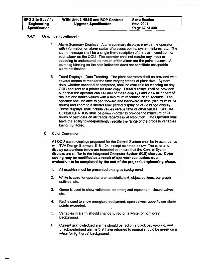
NPG Site-Specific WBN Unit 2 NSSS and BOP Controls SpecificationEngineering Upgrade Specification Rev. 0001Specification Page 67 of 440
3.4.7 Graphics (continued)
4. Alarm Summary Displays - Alarm summary displays provide the operatorwith information on alarm status of process points, system failures, etc. Thealarm message shall be a single line description of the alarm condition foreach alarm on the ODU. The operator shall not require any index ordecoding to understand the nature of the alarm nor the point in alarm. Apoint tag blinking as the sole indication does not constitute acceptablealarm notification.
5. Trend Displays - Data Trending - The plant operators shall be provided withseveral means to monitor the time varying trends of plant data. Systemdata, whether scanned or computed, shall be available for trending on anyODU and sent to a printer for hard copy. Trend displays shall be providedsuch that the operator can call any of these displays and view all or part ofthe last one hours values with a minimum resolution of 15 seconds, Theoperator shall be able to pan forward and backward in time (minimum of 24hours) and zoom to a shorter time period display or value range display.These displays shall include values versus time or other values. SPECIALCONSIDERATION shall be given in order to provide the minimum of 24hours of past data on all trends regardless of resolution. The Operator shallhave the ability to independently rescale the range of the process variablesbeing monitored.
C. Color Convention
All ODU based displays proposed for the Control System shall be in accordancewith TVA Design Standard E18.1.24, except as noted below. The color anddisplay conventions below are intended to ensure that the Control Systemdisplays are similar to the Integrated Computer System (ICS) displays. Colorcoding may be modified as a result of operator evaluation; suchevaluation to be completed by the end of the project's engineering phase.
1. All graphics must be presented on a gray background.
2. White is used for operator prompts/static text, object outlines, bar graphoutlines, etc.
3. Green is used to show valid data, de-energized equipment, closed valves,etc.
4. Red is used to show energized equipment, open valves, upper/lower alarmpoints exceeded.
5. Variables in alarm should change to red on a white (or light gray)background.
6. Current acknowledged alarms should be red on a black background, andunacknowledged alarms that have returned to normal should be green on awhite (or light gray) background.
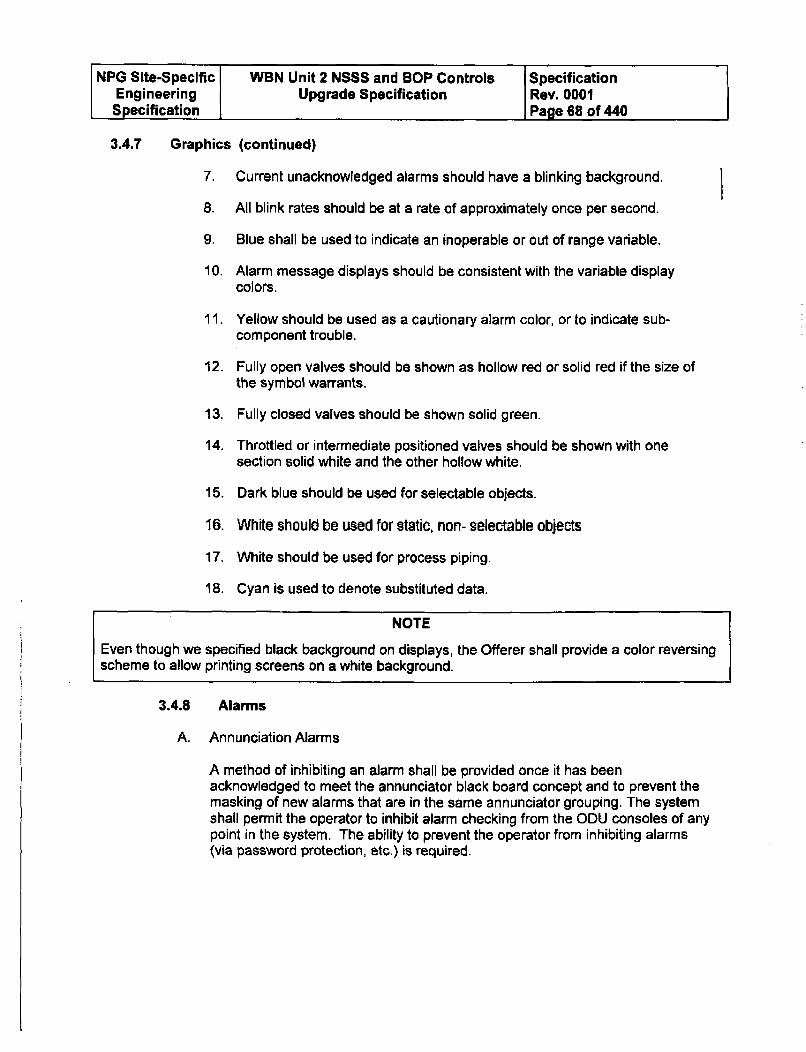
NPG Site-Specific WBN Unit 2 NSSS and BOP Controls SpecificationEngineering Upgrade Specification Rev. 0001Specification Page 68 of 440
3.4.7 Graphics (continued)
7. Current unacknowledged alarms should have a blinking background.
8. All blink rates should be at a rate of approximately once per second.
9. Blue shall be used to indicate an inoperable or out of range variable.
10. Alarm message displays should be consistent with the variable displaycolors.
11. Yellow should be used as a cautionary alarm color, or to indicate sub-component trouble.
12. Fully open valves should be shown as hollow red or solid red if the size ofthe symbol warrants.
13. Fully closed valves should be shown solid green.
14. Throttled or intermediate positioned valves should be shown with onesection solid white and the other hollow white.
15. Dark blue should be used for selectable objects.
16, White should be used for static, non- selectable objects
17. White should be used for process piping.
18. Cyan is used to denote substituted data.
NOTE
Even though we specified black background on displays, the Offerer shall provide a color reversingscheme to allow printing screens on a white background.
3.4.8 Alarms
A. Annunciation Alarms
A method of inhibiting an alarm shall be provided once it has beenacknowledged to meet the annunciator black board concept and to prevent themasking of new alarms that are in the same annunciator grouping. The systemshall permit the operator to inhibit alarm checking from the ODU consoles of anypoint in the system. The ability to prevent the operator from inhibiting alarms(via password protection, etc.) is required.
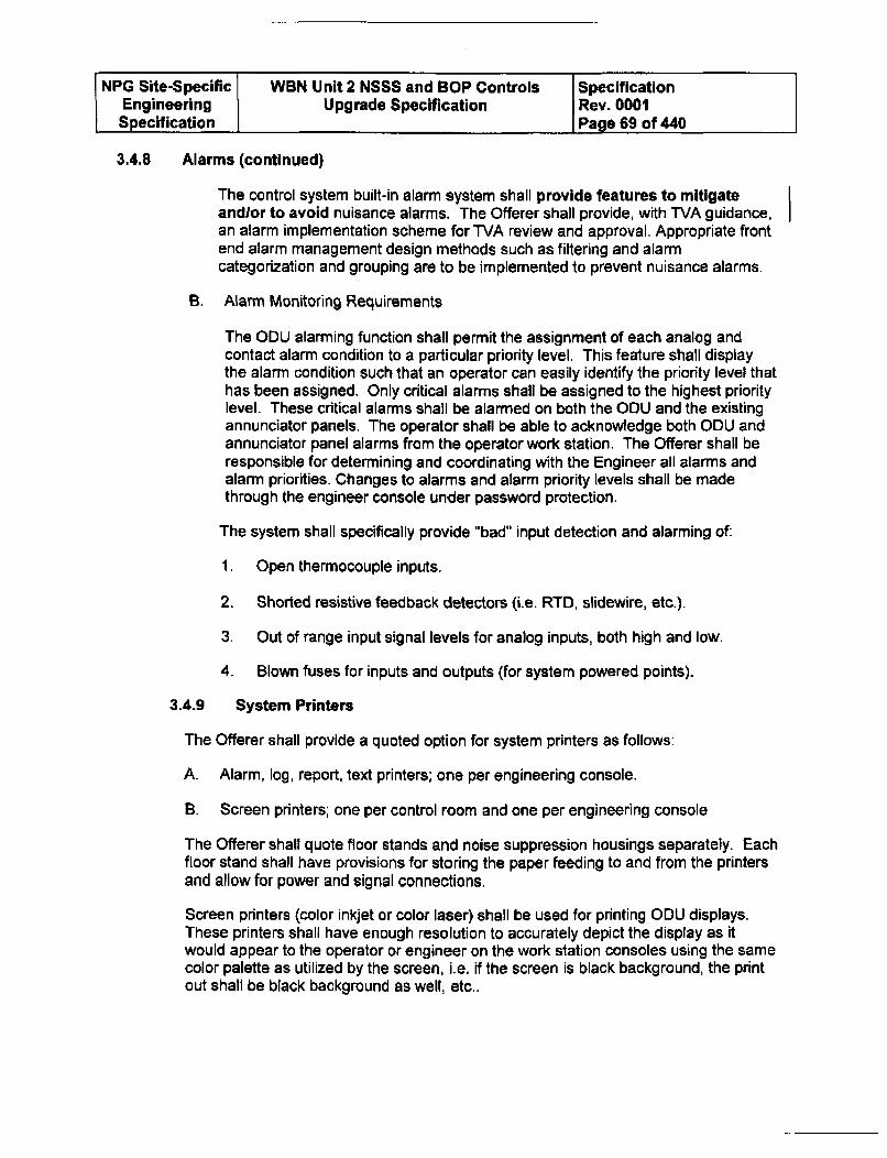
NPG Site-Specific WBN Unit 2 NSSS and BOP Controls SpecificationEngineering Upgrade Specification Rev. 0001Specification Page 69 of 440
3.4.8 Alarms (continued)
The control system built-in alarm system shall provide features to mitigateandlor to avoid nuisance alarms. The Offerer shall provide, with TVA guidance,an alarm implementation scheme for TVA review and approval. Appropriate frontend alarm management design methods such as filtering and alarmcategorization and grouping are to be implemented to prevent nuisance alarms.
B. Alarm Monitoring Requirements
The ODU alarming function shall permit the assignment of each analog andcontact alarm condition to a particular priority level. This feature shall displaythe alarm condition such that an operator can easily identify the priority level thathas been assigned. Only critical alarms shall be assigned to the highest prioritylevel. These critical alarms shall be alarmed on both the ODU and the existingannunciator panels. The operator shall be able to acknowledge both ODU andannunciator panel alarms from the operator work station. The Offerer shall beresponsible for determining and coordinating with the Engineer all alarms andalarm priorities. Changes to alarms and alarm priority levels shall be madethrough the engineer console under password protection.
The system shall specifically provide "bad" input detection and alarming of:
1. Open thermocouple inputs.
2. Shorted resistive feedback detectors (i.e. RTD, slidewire, etc.).
3. Out of range input signal levels for analog inputs, both high and low.
4. Blown fuses for inputs and outputs (for system powered points).
3.4.9 System Printers
The Offerer shall provide a quoted option for system printers as follows:
A. Alarm, log, report, text printers; one per engineering console.
B. Screen printers; one per control room and one per engineering console
The Offerer shall quote floor stands and noise suppression housings separately. Eachfloor stand shall have provisions for storing the paper feeding to and from the printersand allow for power and signal connections.
Screen printers (color inkjet or color laser) shall be used for printing ODU displays.These printers shall have enough resolution to accurately depict the display as itwould appear to the operator or engineer on the work station consoles using the samecolor palette as utilized by the screen, i.e. if the screen is black background, the printout shall be black background as well, etc..
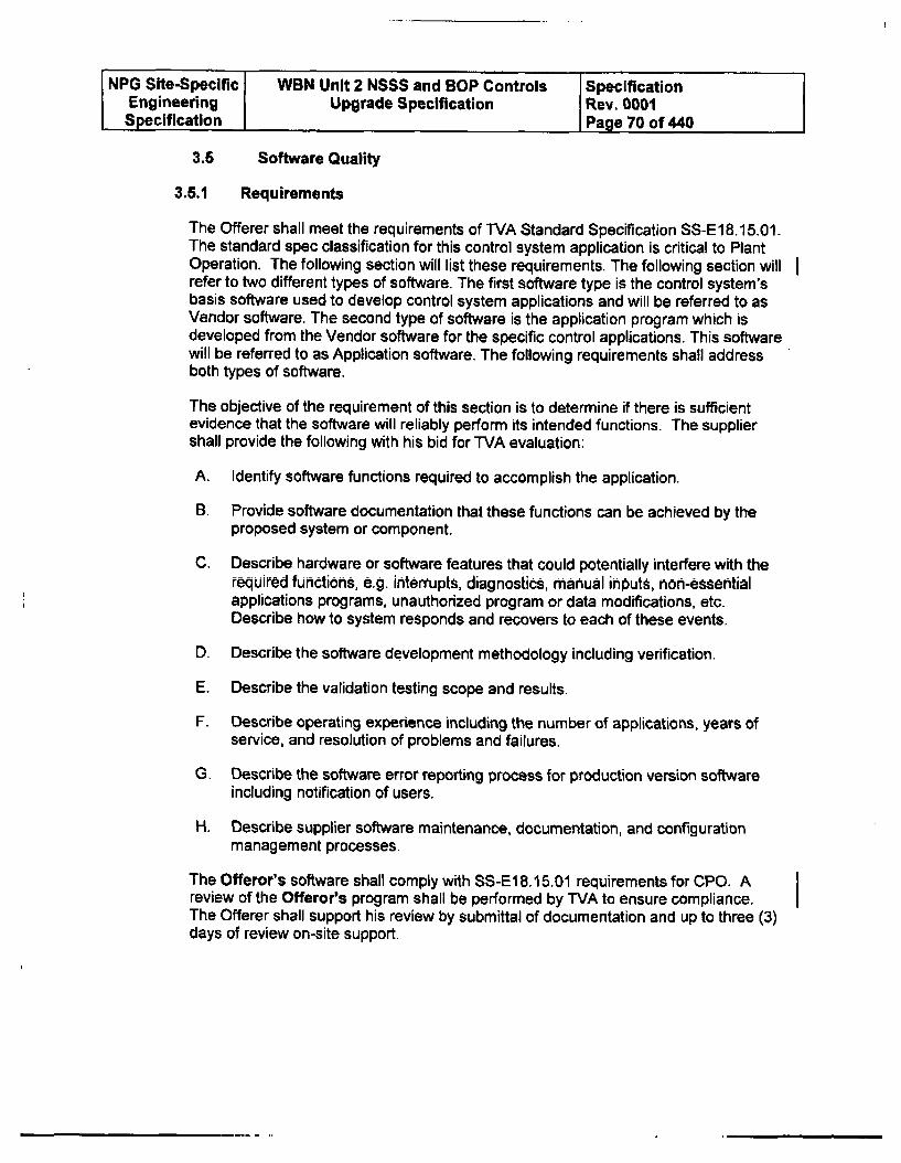
NPG Site-Specific WBN Unit 2 NSSS and BOP Controls SpecificationEngineering Upgrade Specification Rev. 0001Specification Page 70 of 440
3.6 Software Quality
3.6.1 Requirements
The Offerer shall meet the requirements of TVA Standard Specification SS-E18.15.01.The standard spec classification for this control system application is critical to PlantOperation. The following section will list these requirements. The following section willrefer to two different types of software. The first software type is the control system'sbasis software used to develop control system applications and will be referred to asVendor software. The second type of software is the application program which isdeveloped from the Vendor software for the specific control applications. This softwarewill be referred to as Application software. The following requirements shall addressboth types of software.
The objective of the requirement of this section is to determine if there is sufficientevidence that the software will reliably perform its intended functions. The suppliershall provide the following with his bid for TVA evaluation:
A. Identify software functions required to accomplish the application.
B. Provide software documentation that these functions can be achieved by theproposed system or component.
C. Describe hardware or software features that could potentially interfere with therequired functions, e.g. interrupts, diagnostics, manual inputs, h0h-essentialapplications programs, unauthorized program or data modifications, etc.Describe how to system responds and recovers to each of these events.
D. Describe the software development methodology including verification.
E. Describe the validation testing scope and results.
F. Describe operating experience including the number of applications, years ofservice, and resolution of problems and failures.
G. Describe the software error reporting process for production version softwareincluding notification of users.
H. Describe supplier software maintenance, documentation, and configurationmanagement processes.
The Offeror's software shall comply with SS-El 8.15.01 requirements for CPO. Areview of the Offeror's program shall be performed by T'VA to ensure compliance.The Offerer shall support his review by submittal of documentation and up to three (3)days of review on-site support.
NPG Site-Specific WBN Unit 2 NSSS and BOP Controls SpecificationEngineering Upgrade Specification Rev. 0001Specification Page 71 of 440
3.6.2 Software Quality Assurance Plan (SQAP)
The Offerer shall develop and submit for TVA approval their SOAP for both theVendor and application software as required by WVA Standard Specification SS-E18.15.01. Refer to IEEE Standard 730.1-1989 for guidance for SQAP development.
3.5.3 Software Requirements Specification
The Offerer shall use this Engineering Specification as the Software RequirementsSpecification (SRS) for the Application software.
3.5.4 Software Design Description
The Offerer shall develop and submit for WVA approval a Software DesignDescription, which may consist of text, tables, drawings, etc., as required by TVAStandard Specification SS-E18.15,01. Graphical configuration drawings can be usedto meet this requirement but must be submitted and approved by WVA.
3.5.5 Verification and Validation (V&V)
The surveillance activity identified below may include the need for TVA toaccess and review material that the Offeror considers to be proprietary orintellectual property. The surveillance shall occur following appropriatecommericial non-disclosure agreement(s) that islare acceptable to TVA and tothe Offeror.
A. Verification
For the Vendor software, the Offerer shall permit WVA to conduct asurveillance activity to review its software verification process and list theinternal document that implements this process for TVA's revew. For theApplication software, the Offerer's and TVA's design reviews will be used toperform software verification.
B. Validation
For the Vendor software, the Offerer shall permit TVA to conduct asurveillance activity to review its software validation process and list theinternal document that implements this process for TVA's review. For theApplication software, the testing will be used to perform software validation. Thistesting will consist of: 1) a comprehensive Factory Acceptance Test (FAT)performed by the Offerer and witnessed by WVA; 2) Simulator Testing performedby WVA; 3) Post Modification Testing performed by TVA with support from theOfferer.
C. Burn In Testing
The complete system shall be powered up and operating (open loop acceptable)uninterrupted for a minimum of 2 weeks. Should be performed prior to FAT.
NPG Site-Specific WBN Unit 2 NSSS and BOP Controls SpecificationEngineering Upgrade Specification Rev. 0001Specification Page 72 of 440
3.5.5 Verification and Validation (V&V) (continued)
D. Factory Acceptance Testing (FAT)
The FAT shall be a comprehensive test that verifies all control systemperformance requirements, hardware and software. Testing shall include bothopen and closed loop testing. This testing shall be performed with all plantspecific configuration parameters (provided or approved by WVA) implemented.TVA shall prepare a FAT scoping document and the Offerer shall prepare a FATplans and procedures to implement the scoping document. The FAT Plan andProcedures shall be submitted to WVA for review and approval beforeperformance. All test anomalies shall be resolved with TVA. Shipment withunresolved anomalies shall occur only with TVA's approval. The executedFAT Plan and Procedures shall be submitted to TVA for final review andapproval.
E. Simulator Testing
The Plant Simulator will be used to perform process control system testing. Insupport of this testing, the Offerer shall propose in the bid a recommendedmethod for TVA to implement the control system upgrades into the WBNSimulators such as the Offerer providing computer system that implements thecontrol system software and interfaces with the Simulators or directly updatingthe Simulators with the upgraded control system software. This should becoordinated with Section 2.2, Simulator upgrade.
F. Post Modification Testing
The Offerer shall propose technical support for startup testing and associatedcosts for this service. See section on Startup support. Support personnel shallbe from the Offerer's design and development project team. Individuals withspecialized startup support expertise can be used to augment startup support.
3.5.6 V&V Report
The Offerer shall submit a V&V Report that documents design reviews andreferences the FAT results and vendor software V&V. All software and hardwarebaselines (both Vendor and application software along with needed software tools)and revision levels shall be documented in the report.
3.5.7 Software Configuration
All software will be configured by the Offerer using a controlled development processwith configuration controls that will provide a quality product.
NPG Site-Specific WBN Unit 2 NSSS and BOP Controls SpecificationEngineering Upgrade Specification Rev. 0001Specification Page 73 of 440
3.5.8 Configuration Control
For both Vendor and Application software, the Offerer shall submit their softwareconfiguration control process and the internal document that implements this processfor IVA's review. The Offerer shall recommend the best method for TVA to maintainconfiguration control of both hardware and software upon delivery and acceptance ofthe control system.
3.6.9 User Manuals
The Offerer shall provide 5 sets of User manuals for hardware, software, and graphicsapplication.
3.5.10 Training
Training is addressed in the Training section of this specification.
3.5.11 Security
Security is addressed in the Security section of this specification.
3.5.12 Software Tagging
Software tagging (software point identification) convention shall be developed by TVAbased upon the Offerer's software configuration capabilities.
3.6 Interface Requirements
3.6.1 Interface with Other Systems
Any control system inputs that are received from safety systems shall be provided viaisolators located in the safety system's enclosures (not in Non-Safety enclosures) andwill be at a non-IE signal level required by the control system. To eliminate thepotential for mid scale failures, analog inputs and outputs shall not represent bipolarvoltage combinations, where the signal passes through zero. Signals with live zerosare recommended.
The control system will receive analog inputs from pressure, temperature, flow, andlevel sensors as shown in Appendix E. Signal conditioning hardware shall be includedin the control system to accept a variety of input types.
Digital interfaces shall be provided for monitoring the control system inputs andoutputs by the plant ICS, transient monitors, etc. Signals supplied to the ICS,indicators, and recorders shall be buffered or isolated to prevent degradation of thecontrol system by any of the following events:
NPG Site-Specific WBN Unit 2 NSS and BOP Controls SpecificationEngineering Upgrade Specification Rev. 0001Specification Page 74 of 440
3.6.1 Interface with Other Systems (continued)
A. Broadcast Storm from ICS network
B. Failure of the digital interface component directly connected to the control system
C. Other credible failures identified in the Hazard Analysis (section 3.2.2.G).
3.6.2 IIO Capacity
The control system shall be designed to adequately manage the minimum quantity ofinputs and outputs listed in Appendix E. The capacity must include 15 percent sparecapacity over the quantity given in Appendix E.
Appendix E shall be defined further by the Offerer for Wafts Bars specific needs (ie.,
alarm output functions)
3.6.3 Field Terminations
The Offerer's system shall have provisions for field terminations (eg,, TerminationAssemblies) for all field 110 signals. These terminations shall be provided as eitherhardwired, screw terminal, or plug type connections (user selectable). Field terminalpoints shall be designed to accommodate up to #12 AWG wiring (specific terminalpoint wire sizes to be determined following contract award). All thermocouple (TC)cold junction compensation shall be provided directly at the field termination areawhere the TC wire terminates to a non match TC metal and the Offerer should limit thenumber of connections (eg., a ring lug is not required for TC's) . The existingterminations of the present system shall be utilized to prevent rewiring of devicesexternal to the control system.
3.6.4 Pneumatics Design
TVA shall replace all affected 10 to 50 mA lIP and any electro-pneumatic positionerswith 4 to 20 mA types. TVA shall determine the selected vendor and type.
3.7 Maintenance
The equipment shall use standardized, modular, plug in construction so that anycomponent may be easily removed from the system and replaced without breaking ormaking soldered connections. The number of types, kinds, categories, etc., ofcomponents shall be kept to a minimum in order to reduce the spare parts cost. TheOfferer shall provide a recommended periodic replacement frequency for all providedcomponents. Any component with electrolytic capacitors shall specifically identifiedalong with operating and shelf life cycles.
NPG Site-Specific WBN Unit 2 NSSS and BOP Controls SpecificationEngineering Upgrade Specification Rev. 0001Specification Page 75 of 440
3.7.1 Troubleshooting
Each module should contain both red and green status LEDs (these colors arepreferred but not required). Green indicates when a module is functioning properly andred indicates failure. When detected the failed module identifier shall be displayedon the Engineering Workstation and Operator's Console and a cross reference tomodule type and location shall be provided.
3.7.2 Testing, Calibration, and Verification
Capability shall be provided for online tuning and testing of the channels and thedevices used to derive the various channel output signals. Capability to perform onlineself tuning shall also be provided.
The control system shall permit the administrative control (password and/or keylock)of access to all setpoint adjustments and tuning values. For configuration controlpurposes, it shall be possible to view the current revision level of theapplication software from the engineering workstation.
3.7.3 Channel Bypass or Removal from Operation
The control system shall be designed to permit any input or output to be removed fromoperation or bypassed for maintenance or testing during power operation. The designshall provide for administrative control of the means for manually bypassing thechannels. Channel bypassing shall be inhibited where bypassing would place theoutput of a redundant handling scheme into BAD quality (ie., one signal already in badquality).
If a channel has been bypassed or deliberately rendered inoperable, this conditionshall be available within the control system.
Channel bypass activities shall be performed from maintenance graphics screens.
3.8 Equipment Cabinets
The control system shall be housed in Seismic Category I(L) cabinets. Theequipment cabinets are fully enclosed with hinged access doors in the front and rear.
Offerer shall perform walkdown to determine details such as dimensions, mounting,cable entry, etc. Refer to Section 2.8.3.1 for seismic qualification requirements,Cabinet drawings and critical information such as center of gravity shall be submittedfor TVA review.
A control system shall not need forced ventilation to ensure reliability. If the controlsystem requires a ventilation system, it shall be fully 100% redundant complete withblower, inlet fihter, and controls to enhance the reliability of the equipment. However, itis deemed as not being desirable and will be viewed as an exception to thespecification. If a ventilation system is furnished, annunciation on the loss of coolingair shall be provided. Temperature sensors with associated control system alarmswithin each cabinet shall be provided.
NPG Site-Specific WBN Unit 2 NSSS and BOP Controls SpecificationEngineering Upgrade Specification Rev. 0001Specification Page 76 of 440
3.9 Accuracies
Channel accuracy is defined to include the accuracy of the primary element,transmitter, rack modules and any process or environmental effects on field mountedhardware. The control accuracy is defined to include the channel accuracy plus theaccuracy of any isolators in the system, the controller accuracy and the rackenvironmental effects. The control accuracy does not include errors for the time inwhich the system is in a non-steady state condition. Refer to Section 3.2.1 .G.3 foradditional loop accuracy requirements.
3.9.1 Control System Processing Accuracies
Refer to Section 3.2.1.G.3.
3.9.2 System Accuracy Requirements
The overall control system's inaccuracies plus process inaccuracies shall not exceedthe system accuracy requirements defined in the individual System Requirementssections.
3.10 Response Time Requirements
The response time requirements for the C&MS are described in the System FunctionalRequirement sections of this specification.
3.10.1 Anti-Aliasing Filtering
The System shall provide the capability to enable anti-aliasing filtering for all inputsignals of the C&MS. This requirement includes all input process channels utilized forcontrol, interlocks, and permissives within the noted system(s), and also applies tointerlock and permissive signals calculated outside of but utilized within the ControlSystem.
3.10.2 Control Processors Response Time
The control processor response time (from the control system's input module/s tooutput module/s including control system processing time) for all input signals of theControl System shall be as specified in the System Functional Requirementslisted in Sections 4 through 12 below. This requirement includes all input processchannels utilized for control, interlocks, and permissives within the noted system(s),and also applies to interlock and permissive signals calculated outside of but utilizedwithin Control System. This requirement includes all modulating control signals,bistable logic (on/off) control signals, and mode signals. The signals to the maincontrol board (indication, status, and alarm/annunciators) should have a minimumupdate rate of 1 second unless otherwise specified.
NPG Site-Specific WBN Unit 2 NSSS and BOP Controls SpecificationEngineering Upgrade Specification Rev. 0001Specification Page 77 of 440
3.10.3 Communication Response Time between ControlProcessors
For future expansion, the C&MS shall have the capability to communicate betweendifferent Control Processor pairs as specified in the System FunctionalRequirements listed in sections 4 through 12 below.
3.10.4 Manual Control Response
The total delay for all manual component control signals of C&MS shall be no greaterthan 1 second.
3.11 System Acceptance Test Requirements
The purpose of the system acceptance tests is to determine, and the underlyingstandard for system acceptance shall be, compliance in every respect with thisRequirements Specification. All materials furnished and all work performed under thisspecification shall be subject to four acceptance tests - a Factory Acceptance Test(FAT) at the Offerer's facility prior to delivery, an EMI/RFI Test (or completion of theSequoyah test/evaluation) prior to delivery, a Site Acceptance Test (SAT) afterdelivery at a staging location, and a Post Modification Test (PMT) after installation ofthe system. The FAT will be conducted, directed, and performed by the Offerer withTVA representatives as witnesses. The SAT and PMT will be conducted, directed,and performed by TVA representatives with full cooperation and assistance ofOfferer's representatives. All tests will be of the entire system in its final configurationincluding the specific equipment and software to be delivered; no substituteequipment, cables, or software will be used unless approved by the Lead ElectricalEngineer. TVA-supplied field cables are understood to be replaced by factorytest cables for testing purposes. WVA will take measures to test the field cablesin situ and confirm their continuity and attenuation.
If a test indicates the hardware or software does not meet the specificationrequirements, the Offerer shall replace, modify, or add at no cost to TVA anyhardware, software or documentation and retesting necessary to correct the notedanomalies.
The Offerer shall submit to TVA a recommended test procedure for the FAT, EMIIRFI,and SAT. The performance of all the procedures shall verify the ability of the Systemto individually and simultaneously fulfill all functions and requirements as set forth inthis Specification. The Offerer shall make a recommendation on what the PMT scopeshould be.
The Engineer will only approve the test procedure if it is inclusive and tests eachsegment of the system and designed function both independently and collectively. Noformal testing will begin until the complete test procedure is agreed to. Each individualtest procedure shall detail the purpose of the test, inputs, procedures, outputs to theachieved, and acceptance criteria. The test procedures shall include periods forunstructured exercising of the hardware and software by TVA's representatives.
NPG Site-Specific WBN Unit 2 NSSS and BOP Controls SpecificationEngineering Upgrade Specification Rev. 0001Specification Page 78 of 440
3.11 System Acceptance Test Requirements (continued)
Any unsuccessful Test will be repeated at least once and, if again unsuccessful, willbe repeated only at TVA's option. If, for any reason, any test is stopped, TVA willdetermine the restart point. However, after any unsuccessful test(s), (that is, anAuthorization to Ship or System Acceptance Acknowledgment, is not issued), theOfferer shall reimburse WVA $5,000 in Liquidated Damages for each occurrence. Ifthe Tests are not successfully completed, TVA will have the right to terminate theContract. In such event, TVA will, unless otherwise mutually agreed to by the partiespromptly return the System and all System Documentation to the Offerer at theOfferer's expense and will have the right to receive prompt reimbursement of allpayments made to the Offerer. Successful completion of the Acceptance Tests shallnot waive, release or otherwise relieve the Offerer of any obligation or liability arisingunder the Contract.
3.11.1 Electro Magnetic (EMI) and Radio Frequency Interference(RFI)
EMI and RFI tests are required in accordance with WVA Standard Specification SSEl 8.14.01. However, the Offerer may substitute his standard EMI/RFI test or theSequoyah project test report, if approved by TVA.
3.11.2 Factory Acceptance Testing (FAT)
The FAT shall be a comprehensive test that verifies all control system requirements,hardware and software. Testing shall include both open and closed loop testing. Thistesting shall be performed with all plant specific configuration parameters (provided orapproved by TVA) implemented. WVA shall prepare a FAT scoping document and theOfferer shall prepare a FAT Plan and Procedures to implement the scopingdocument. The FAT Plan and Procedures shall be submitted to TVA for review andapproval before performance. All test anomalies shall be resolved with TVA beforecontrol system shipment.
The system hardware and software configuration tested in the factory shall be theconfiguration installed and tested at the site. This specifically applies to allinterconnect cables. The Offerer shall insure by proper and complete tagging plusproper documentation that each and every cable connected at the site is exactly thesame as was tested at the factory.
In addition to the diagnostic software required by the Specification, the Offerer shallprovide all testing software and calibrated test equipment required to demonstrate theacceptable operation of all hardware units and subsystems. WVA, at its option, mayuse TVA's own test equipment during the test. Test software descriptions and listingsshall be submitted as part of the Offerer's test procedure.
NPG Site-Specific WBN Unit 2 NSSS and BOP Controls SpecificationEngineering Upgrade Specification Rev. 0001Specification Page 79 of 440
3.11.2 Factory Acceptance Testing (FAT) (continued)
Tests shall include realistic message traffic on all communications networks andsubnetworks. In addition, all digital interfaces to external environments such as plantcomputer interface shall be tested to withstand broadcast storm events withoutdegradation in the control systems performance. Also, the control system shall betested for broadcast storm events resulting from component failures on internalcommunication networks without degradation in the control systems performance.
Power failure tests shall require the Offerer to have two breakers (in the factory) forthe system.
A. The Factory Acceptance Test will not be initiated by WVA until all of the followinghave occurred:
1. The Offerer has successfully accomplished the Burn in Testing and fullydocumented the test results, and TVA has been notified in writing of thesuccessful completion of this test.
2. The Offerer has delivered to the Engineer, the Offerer's proposed completefinal draft of the required System Documentation.
B. The Factory Acceptance Test shall cover four basic activities:
1. 1/0 Testing and Binary Logic Testing - Each and every Inplut and Outputshall be tested for proper wiring, powering, fusing, and scaling withverification of proper operation on the operator console display. The binarycontrol logic shall be thoroughly tested to simulate actual control loopexecution to verify proper sequence of operation, correct true/false stateinterpretation, correct tagout response, and correct depiction of the controlloop on the operator console displays. All binary control loop testing shallbe closed loop simulation via the use of switches.
2. Engineering Workstations and Operator Consoles Graphic Functional Test -Each and every graphic display shall be reviewed to assure correct displayof data, paging, adherence to the design conventions, speed of response,and other elements associated with the configured operator console.
3. Modulating Control Verification - The Offerer shall demonstrate the properoperation of all modulating control loops with complete closed loopsimulation via connection to the Offerers factory test simulator after the I/Ois tested. The testing shall include system power failures, communicationfailures, and a complete restart after simulated black plant event.
4. Closed loop simulation testing - Test cases to be determined by TVA.
Upon successful completion of the FAT, TVA will issue an "Authorization to Ship"allowing Offerer to deliver the System.
Also see Software Validation Testing Section for details.
NPG Site-Specific WBN Unit 2 NSSS and BOP Controls SpecificationEngineering Upgrade Specification Rev. 0001Specification Page 80 of 440
3.11.3 Site Acceptance Test (SAT)
After delivery at the Installation Site, the SAT will be conducted by TVArepresentatives assisted by Offerer representatives. The Site Acceptance Test isintended to be a complete procedure for the Offerer's Field Service Engineer toascertain that the system is performing as it had during the Factory Acceptance Testincluding correction of any punchlist items from the FAT. TVA will have the right, afternotice to Offerer, to waive the SAT.
3.11.4 Simulator Upgrade and Testing System
See Software Validation Testing Section for details.
3.11.5 Post Modification Test (PMT)
The Offerer shall propose technical support for startup testing and associated costs forthis service. See section on Startup support. Support personnel shall be from theOfferer's design and development project team. Individuals with specialized startupsupport expertise can be used to augment startup support,
After the Control System is installed at the plant (post Control System installation) thePMT will be conducted by TVA representatives assisted by Offerer representatives.When the PMT is successfully completed, TVA will issue to the Offerer a dated"System Acceptance Acknowledgment."
The PMT and FAT shall provide I/O overlap testing for the control system.
3.12 Long Term Support
Because of the increased probability of equipment obsolescence when using digitalhardware, the Offerer must provide a commitment that system equipment will not beobsolete within the next ten years. Since portions of the system will eventually bewithdrawn from sale, a firm commitment shall be required from the manufacturerensuring that repair capability, equivalent parts and/or the withdrawn products willremain available for a minimum of ten years from the withdrawal date. If the Offerer isunable to provide the required hardware and/or software, or their support, during thisperiod due to obsolescence, unavailability, or the like, the Offerer shall provide a like-kind replacement available subject to the approval of TVA. In any case, any substituteor upgrade shall meet the requirements of this specification both as a component andas a system.
The Offerer shall have at least 20 years experience providing control and monitoringsystems to the Electrical Utility Industry. The Offeror shall provide evidence ofsystems experience in the Electric Utility Industry. This could take the form ofreference installations that could either be visited or contacted by phone or letter,and/or by joint advertisements (with an end user).
The Offerer shall state whether or not their components are RoHS compliant andidentify any components that are not compliant.
NPG Site-Specific WBN Unit 2 NSSS and BOP Controls SpecificationEngineering Upgrade Specification Rev. 0001Specification Page 81 of 440
3.13 Spare Parts
The bidder shall submit a recommended spare parts list with the formal proposal. Onespare part for each component of the control system shall be provided. Spare parts forthe simulator modification shall be procured with the control system (see the Simulatorsection).
-J
3.14
A.
B.
C.
D,
E.
F.
G.
H.
1,
Miscellaneous System Requirements
All switches and fuses must be identified with unique labels.
All terminals and terminal blocks shall be labeled and have screw terminalconnections suitable for use with ring type lugs (see exception in section 3.6.3for TCs).
All mechanical relay contacts shall be enclosed to prevent contamination.
Set screw connections of stranded wire less than #14 AWG are not acceptableanywhere in the equipment. Acceptable set screw connections are limited to acpower and system ground cables.
All materials used shall have inherent flame retardant characteristics.
Aluminum conductors may be used only with the TVA's written approval.
All bidder supplied wiring and cable shall be abrasion resistant and have non-PVC insulation and flame retardant certification.
Terminal lugs shall be ring tongue nylon insulated or a TVA approved equal.
Separate terminal blocks shall be provided for power connectors and I/Oconnections.
J. Internal power cabling/wiring shall be separated from IO cabling/wiring.
K. Terminals for I/O connections shall accommodate TVA's #12 to 16 AWGconductors.
L. Terminals for power connections shall accommodate the wire size appropriatefor the appropriate load, but not less than #12 AWG.
M. All internal wiring for I/O shall be twisted pair and shielded to the extent feasible.
N. Equipment layout shall be such as to minimize the amount of inter-panel wiringrequired.
3.15 References
A. Standard Specification SS-E18.14.01 R3 - "Electromagnetic Interference (EMI)Testing Requirements for Electronic Devices"
NPG Site-Specific WBN Unit 2 NSSS and BOP Controls SpecificationEngineering Upgrade Specification Rev. 0001Specification Page 82 of 440
3.15 References (continued)
B. Standard Specification SS-El 8.15.01 RI - "Software Requirements for Real-Time Data Acquisition and Control Computer Systems"
C. Electrical Design Guide DS-E18.1.24 - "Human Factor Engineering DesignStandard"
D. WBN Design Criteria for Seismic Qualification, WB-DC-40-31.13, "SeismicQualification of Category 1 (L) Fluid System Components and Electrical orMechanical Equipment"
The above Criteria and Standards have been considered in preparing therequirements of this specification.
4.0 STEAM GENERATOR LEVEL CONTROL SYSTEMREQUIREMENTS
The following sections provide general description of WBN's SGL Control Systems.Detail information such as setpoint, scaling, tuning constants, etc. will be providefollowing contract award based upon proprietary conditions.
4.1 System Description
The Steam Generator Level control system is composed of those controllers andassociated hardware whose primary function is to regulate the flow of feedwater intothe steam generator. The system serves to maintain a programmed water level in theshell side of the steam generator during steady state operation without operatorintervention during all plant operating modes from approximately 0 to 100 percentpower. The control system limits the water level shrink and swells during planttransient preventing an undesirable reactor trip actuation. Indicators are provided formonitoring system operation. Steam Generator level fluctuations must be limitedduring normal plant transients within a range which will prevent spurious reactor trips.Computational equipment must be programmable using microprocessor-based digitalhardware to optimize system response to changing process conditions, controlelement characteristics, and component failures. Alarms and annunciators areprovided to alert the plant operator of control system malfunctions or abnormaloperating conditions. A Median Signal Selector (MSS) for the steam generator levelchannel inputs is provided to prevent channel failures from causing disturbances in theSGL control system.
NPG Site-Specific WBN Unit 2 NSSS and BOP Controls SpecificationEngineering Upgrade Specification Rev. 0001Specification Page 83 of 440
4.2 SGL Control System
The SGL control system includes signal processing components and controllerswhose primary function is to regulate the flow of feedwater to the steam generators.The system serves to maintain a programmed water level in the shell side of thesteam generator during steady state operation, and to provide stable system operationby limiting the water level shrink and swell during plant transients to preventundesirable reactor trip actuation. Alarms and annunciators are provided to alert theplant operator of control system malfunctions or abnormal operating conditions.
The flow of feedwater is regulated by throttling action of the feedwater regulatingvalves to maintain a constant steam generator water level and by varying speed of themain feedwater pumps to maintain a programmed differential pressure between themain feedwater header and main steam header. The feedwater regulating valve andthe feed pump speed controls are complementary parts of the feedwater controlsystem.
Primary inputs for the control system are steam generator level and pressure,pressure compensated steam flow, feedwater flow and pressure, and NIS (WBN). Amedian value of the three steam generator level channels is selected by the mediansignal selector function of the feedwater control system for Steam Generator (SG)level control input and combined with steam flow/feedwater flow mismatch signal. Thesteam/feedwater header differential pressure setpoint is varied linearly according tototal steam flow.
4.2.1 Normal Feedwater Control
Feedwater flow (FW) is controlled by the Main Feedwater (MFW) reg valve through athree-element control system. The inputs into the control system are steam flow,feedwater flow, and SG level (see Figure 4.1 of this section). Each of the four SGloops has a separate SGL control system and the SGL setpoint is determined by NIS(function of reactor power). The regulation of FW flow is aided by the use of a MFWspeed control system. The feed pump control system consists of the following threeinterrelated parts:
A. Program differential pressure (DP) setpoint calculator which sums the foursteam flows, provides the lag on setpoint changes, and contains the basicscaling adjustments.
B. The DP control which compares the steam header pressure, FW headerpressure, and the calculated setpoint to determine the speed signal required(reset action is provided in this controller to reduce the steady-state operatingerror).
C. MFP manual-auto stations (MCR mounted one per pump) which are setup asproportion only control mode and provides the operator with the flexibility ofchoosing various operating modes. The capability to bias the two pumps fromone another shall be provided. There is also a MFP (MCR mounted) mastermanual - auto station that provides simultaneous control of both MFPs.
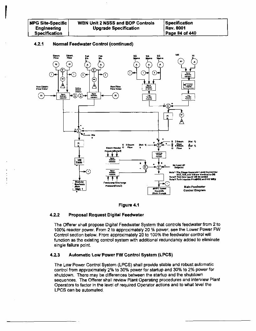
NPG Site-Specific WBN Unit 2 NSSS and BOP Controls SpecificationEngineering Upgrade Specification Rev. 0001Specification Page 84 of 440
4.2.1 Normal Feedwater Control (continued)
No I.ad CP
Note1I The Stmun GeneitDr Laal ControlaflrBG2 SQ m, a nd S5Oam identical to I6
Natez, Two new input wIM be addadNoteS; Turb Impulse PmSNt• and NIS WBW9
Main FeedwaterControl Diagram
Figure 4.1
4.2.2 Proposal Request Digital Feedwater
The Offerer shall propose Digital Feedwater System that controls feedwater from 2 to100% reactor power. From 2 to approximately 20 % power, see the Lower Power FWControl section below. From approximately 20 to 100% the feedwater control willfunction as the existing control system with additional redundancy added to eliminatesingle failure point.
4.2.3 Automatic Low Power FW Control System (LPCS)
The Low Power Control System (LPCS) shall provide stable and robust automaticcontrol from approximately 2% to 30% power for startup and 30% to 2% power forshutdown. There may be differences between the startup and the shutdownsequences. The Offerer shall review Plant Operating procedures and interview PlantOperators to factor in the level of required Operator actions and to what level theLPCS can be automated.
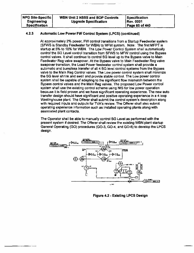
NPG Site-Specific WBN Unit 2 NSSS and BOP Controls SpecificationEngineering Upgrade Specification Rev. 0001Specification Page 85 of 440
4.2.3 Automatic Low Power FW Control System (LPCS) (continued)
At approximately 2% power, FW control transitions from a Startup Feedwater system(SFWS is Standby Feedwater for WBN) to MFW system. Note: The first MFPT isstartup at 5% to 10% for WBN. The Low Power Control System shall automaticallycontrol the SG Level control transition from SFWS to MFW control using the Bypasscontrol valves. It shall continue to control SG level up to the Bypass valve to MainFeedwater Reg valve swapover. At the Bypass valve to Main Feedwater Reg valveswapover transition, the Load Power feedwater control system shall provide aautomatic and bumpless transfer of all 4 SG level control systems from the Bypassvalve to the Main Reg Control valves. The Low power control system shall minimizethe SG level shrink and swell and provide stable control. The Low power controlsystem shall be capable of adapting to the significant flow mismatch between theBypass control valves and the Main Reg valves. The proposed Low Power controlsystem shall use the existing control scheme using NIS for low power operationbecause it is field proven and we have significant operating experience. The new autotransfer design should have significant and positive operating experience in a 4 loopWestinghouse plant. The Offerer shall submit the control system's description alongwith required inputs and outputs for TVA's review. The Offerer shall also submitoperating experience information such as installed operating plants along withassociated plant contacts.
The Operator shall be able to manually control SG Level as performed with thepresent system if desired. The Offerer shall review the existing WBN plant startupGeneral Operating (GO) procedures (GO-3, GO-4, and GO-6) to develop the LPCSdesign.
ni # f P .... ' -cam L I-
4f ""MV
£4',i%, I
i r.".
---- NEW 4 .- 1...
6.1 <3-" =-- =="
Figure 4.2 - Existing LPCS Design
NPG Site-Specific WBN Unit 2 NSSS and BOP Controls SpecificationEngineering Upgrade Specification Rev. 0001
Specification Page 86 of 440
4.2.4 Maintenance Mode (Option)
The Offerer shall provide a separately quoted option, to allow for online maintenanceof the MFW Reg valves. The Bypass Reg valve shall have the ability to be placed intoservice to control level with the MFW Reg valve dogged and in manual. In this mode,the control system shall automatically switch control from the MFW Reg, close it downa predetermined amount while allowing the Bypass Reg valve to open, passing MFWcontrol to the Bypass Reg valve. The Bypass Reg valve would then not only have alevel input, but FW and SF inputs as well, maintaining a full 3-element mode of controlfor that steam generator. The MFW Reg valves then could be "parked" or placed intomanual and be dogged (amount of closure is limited, opening capability isunrestricted) at that position while maintenance takes place. This transfer shall be aseamless transfer and have the proper gains already set up for that type of control. Ifboth controllers are in automatic at the same time, the individual control systems shallnot fight with each other to maintain control of level. The tuning constants for thebypass controls shall automatically change from startup conditions constants topresent operating power level for optimum control.
4.2.5 Main Feedpump (MFP) Speed Controls
In addition to Steam Generator Level controls, MFP speed is varied to maintain aprogrammed pressure differential (dP) between the Main Steam and FW headers. Thespeed controller continuously compares the actual dP with a programmed dP which isa linear function of total steam flow from 20 to 100% power.
4.2.6 MFPT and Standby Pump Recirculation Controls
The MFPT and Standby Main Feed Pump (SBMFP) recirculation control valves (1 perpump) shall be included in the scope of automatic control system. This part of thecontrol system does not require redundant inputs or outputs but shall have failuredetection and failure mitigation protection. Each loop includes a transmitter, squareroot converter, annunciator bistable, indicating PI controller with MCR handstation,and 4-20 MA output signal to the lIP for the control valve. MFP A and MFP B arenondivisional powered. The pump miniflow to the condenser is controlled by an air-operated, fail open valve (FCV-3-70 and -84) which modulates based upon input fromthe pump discharge flow element downstream of the pump discharge. FCV-3-70 and -84 are designed to open on a Feedwater Isolation signal. The MFP minimumrecirculation flow is approximately 4000 gpm (at rated speed) at a shutoff head of2480'. However, during preoperational testing, MFP 1A exhibited high vibrationalsignatures at 4000 gpm recirculation flow at rated speed. Consequently, MFP 1B wasnot tested at 4000 gpm recirculation flow at rated speed but was tested at the lowerend of the variable speed pump curve at approximately 3300 rpm and 2650 gpmrecirculation. Byron Jackson has indicated that the low flow, low gpm recirculation isacceptable. Additionally, this is acceptable because extended operation of the pumpsunder high speed and low flow Is not expected during the life of the plant.
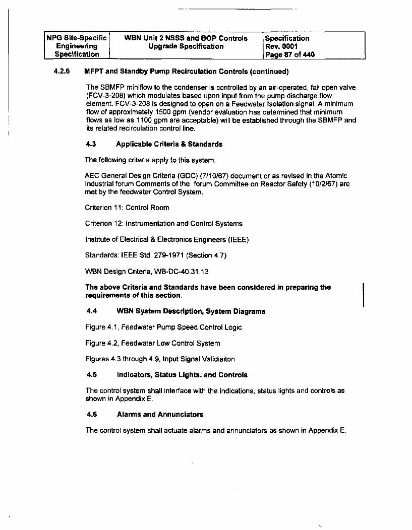
NPG Site-Specific WBN Unit 2 NSSS and BOP Controls SpecificationEngineering Upgrade Specification Rev. 0001Specification Page 87 of 440
4.2.6 MFPT and Standby Pump Recirculation Controls (continued)
The SBMFP miniflow to the condenser is controlled by an air-operated, fail open valve(FCV-3-208) which modulates based upon input from the pump discharge flowelement. FCV-3-208 is designed to open on a Feedwater Isolation signal. A minimumflow of approximately 1500 gpm (vendor evaluation has determined that minimumflows as low as 1100 gpm are acceptable) will be established through the SBMFP andits related recirculation control line.
4.3 Applicable Criteria & Standards
The following criteria apply to this system.
AEC General Design Criteria (GDC) (7/10/67) document or as revised in the AtomicIndustrial forum Comments of the forum Committee on Reactor Safety (10/2/67) aremet by the feedwater Control System.
Criterion 11: Control Room
Criterion 12: Instrumentation and Control Systems
Institute of Electrical & Electronics Engineers (IEEE)
Standards: IEEE Std. 279-1971 (Section 4.7)
WBN Design Criteria, WB-DC-40.31.13
The above Criteria and Standards have been considered in preparing therequirements of this section.
4.4 WBN System Description, System Diagrams
Figure 4.1, Feedwater Pump Speed Control Logic
Figure 4.2, Feedwater Low Control System
Figures 4.3 through 4.9, Input Signal Validiaiton
4.5 Indicators, Status Lights. and Controls
The control system shall interface with the indications, status lights and controls asshown in Appendix E.
4.6 Alarms and Annunciators
The control system shall actuate alarms and annunciators as shown in Appendix E.
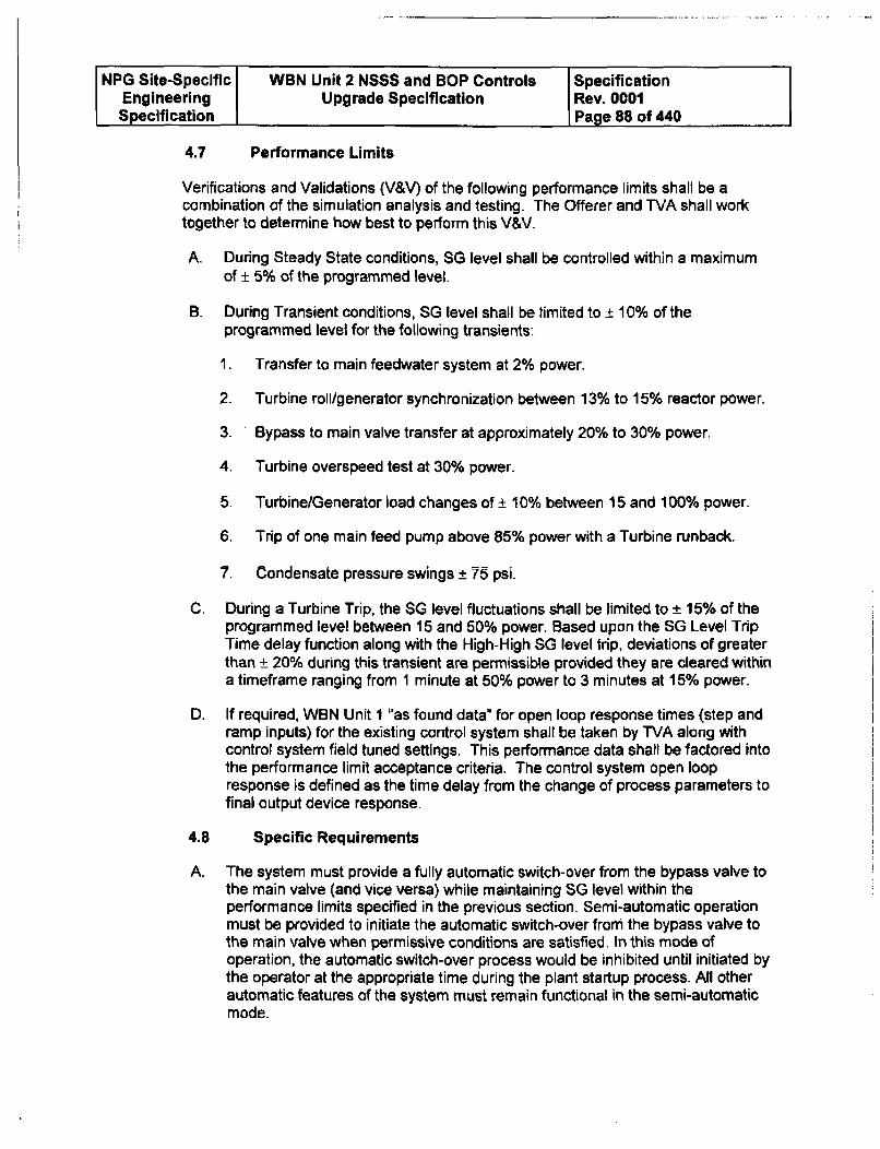
NPG Site-Specific WBN Unit 2 NSSS and BOP Controls SpecificationEngineering Upgrade Specification Rev. 0001Specification Page 88 of 440
4.7 Performance Limits
Verifications and Validations (V&V) of the following performance limits shall be acombination of the simulation analysis and testing. The Offerer and WVA shall worktogether to determine how best to perform this V&V.
A. During Steady State conditions, SG level shall be controlled within a maximumof ± 5% of the programmed level.
B. During Transient conditions, SG level shall be limited to ± 10% of the
programmed level for the following transients:
1. Transfer to main feedwater system at 2% power.
2. Turbine roll/generator synchronization between 13% to 15% reactor power.
3. Bypass to main valve transfer at approximately 20% to 30% power.
4. Turbine overspeed test at 30% power.
5. Turbine/Generator load changes of ± 10% between 15 and 100% power.
6. Trip of one main feed pump above 85% power with a Turbine runback.
7. Condensate pressure swings ± 75 psi.
C. During a Turbine Trip, the SG level fluctuations shall be limited to ± 15% of theprogrammed level between 15 and 50% power. Based upon the SG Level TripTime delay function along with the High-High SG level trip, deviations of greaterthan ± 20% during this transient are permissible provided they are cleared withina timeframe ranging from 1 minute at 50% power to 3 minutes at 15% power.
D. If required, WBN Unit 1 "as found data" for open loop response times (step andramp inputs) for the existing control system shall be taken by TVA along withcontrol system field tuned settings. This performance data shall be factored intothe performance limit acceptance criteria. The control system open loopresponse is defined as the time delay from the change of process parameters tofinal output device response.
4.8 Specific Requirements
A. The system must provide a fully automatic switch-over from the bypass valve tothe main valve (and vice versa) while maintaining SG level within theperformance limits specified in the previous section. Semi-automatic operationmust be provided to initiate the automatic switch-over from the bypass valve tothe main valve when permissive conditions are satisfied. In this mode ofoperation, the automatic switch-over process would be inhibited until initiated bythe operator at the appropriate time during the plant startup process. All otherautomatic features of the system must remain functional in the semi-automaticmode.
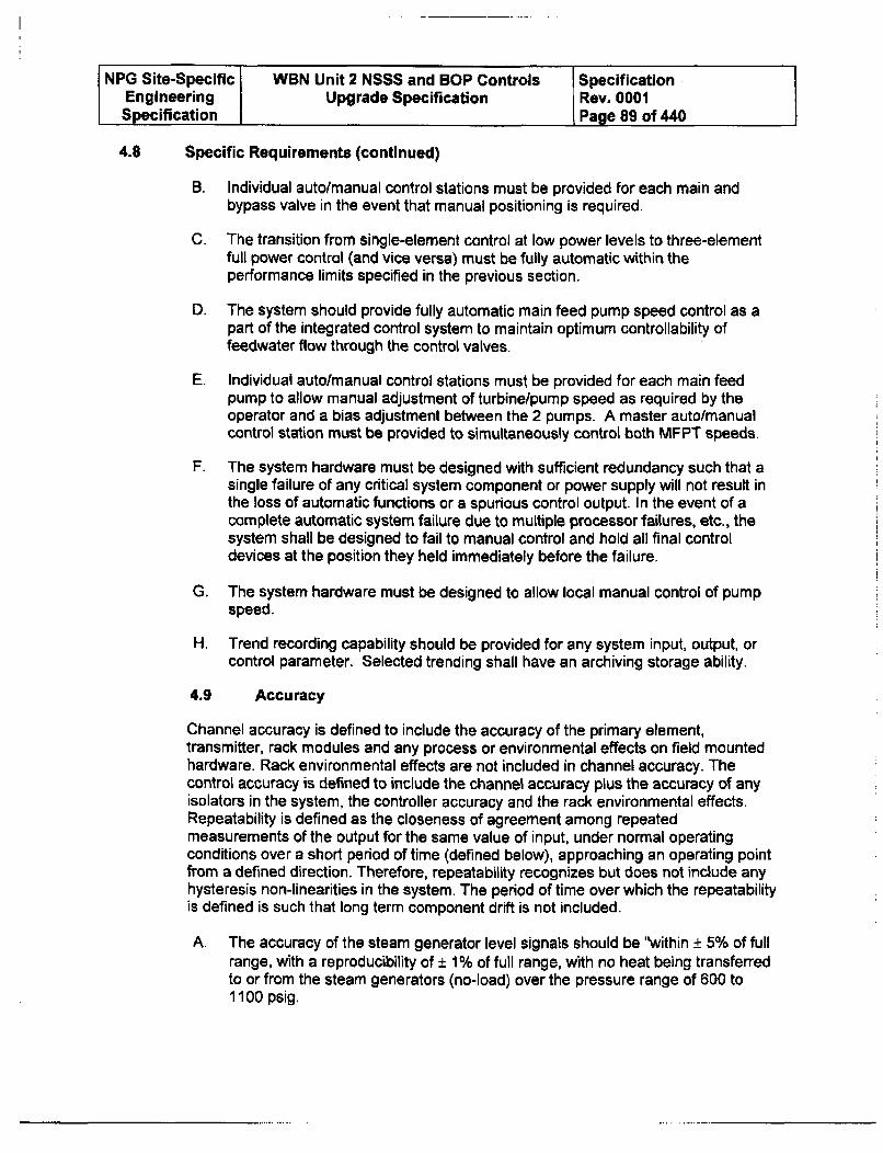
NPG Site-Specific WBN Unit 2 NSSS and BOP Controls SpecificationEngineering Upgrade Specification Rev. 0001Specification Page 89 of 440
4.8 Specific Requirements (continued)
B. Individual auto/manual control stations must be provided for each main andbypass valve in the event that manual positioning is required.
C. The transition from single-element control at low power levels to three-elementfull power control (and vice versa) must be fully automatic within theperformance limits specified in the previous section.
D. The system should provide fully automatic main feed pump speed control as apart of the integrated control system to maintain optimum controllability offeedwater flow through the control valves.
E. Individual autolmanual control stations must be provided for each main feedpump to allow manual adjustment of turbine/pump speed as required by theoperator and a bias adjustment between the 2 pumps. A master auto/manualcontrol station must be provided to simultaneously control both MFPT speeds.
F. The system hardware must be designed with sufficient redundancy such that asingle failure of any critical system component or power supply will not result inthe loss of automatic functions or a spurious control output. In the event of acomplete automatic system failure due to multiple processor failures, etc., thesystem shall be designed to fail to manual control and hold all final controldevices at the position they held immediately before the failure.
G. The system hardware must be designed to allow local manual control of pumpspeed.
H. Trend recording capability should be provided for any system input, output, orcontrol parameter. Selected trending shall have an archiving storage ability.
4.9 Accuracy
Channel accuracy is defined to include the accuracy of the primary element,transmitter, rack modules and any process or environmental effects on field mountedhardware. Rack environmental effects are not included in channel accuracy. Thecontrol accuracy is defined to include the channel accuracy plus the accuracy of anyisolators in the system, the controller accuracy and the rack environmental effects.Repeatability is defined as the closeness of agreement among repeatedmeasurements of the output for the same value of input, under normal operatingconditions over a short period of time (defined below), approaching an operating pointfrom a defined direction. Therefore, repeatability recognizes but does not include anyhysteresis non-linearities in the system. The period of time over which the repeatabilityis defined is such that long term component drift is not included.
A. The accuracy of the steam generator level signals should be "within ± 5% of fullrange, with a reproducibility of ± 1% of full range, with no heat being transferredto or from the steam generators (no-load) over the pressure range of 600 to1100 psig.
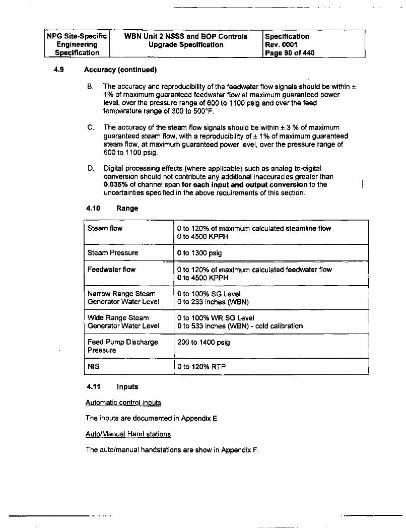
NPG Site-Specific WBN Unit 2 NSSS and BOP Controls SpecificationEngineering Upgrade Specification Rev. 0001Specification Page 90 of 440
4.9 Accuracy (continued)
B. The accuracy and reproducibility of the feedwater flow signals should be within +1% of maximum guaranteed feedwater flow at maximum guaranteed powerlevel, over the pressure range of 600 to 1100 psig and over the feedtemperature range of 300 to 500°F.
C. The accuracy of the steam flow signals should be within ± 3 % of maximumguaranteed steam flow, with a reproducibility of ± 1 % of maximum guaranteedsteam flow, at maximum guaranteed power level, over the pressure range of600 to 1100 psig.
D. Digital processing effects (where applicable) such as analog-to-digitalconversion should not contribute any additional inaccuracies greater than0.035% of channel span for each input and output conversion to theuncertainties specified in the above requirements of this section.
4.10 Range
I
Steam flow 0 to 120% of maximum calculated steamline flow
0 to 4500 KPPH
Steam Pressure 0 to 1300 psig
Feedwater flow 0 to 120% of maximum calculated feedwater flow0 to 4500 KPPH
Narrow Range Steam 0 to 100% SG LevelGenerator Water Level 0 to 233 inches (WBN)
Wide Range Steam 0 to 100% WR SG LevelGenerator Water Level 0 to 533 inches (WBN) - cold calibration
Feed Pump Discharge 200 to 1400 psigPressure
NIS 0 to 120% RTP
4.11 Inputs
Automatic control inputs
The inputs are documented in Appendix E
Auto/Manual Hand stations
The auto/manual handstations are show in Appendix F.
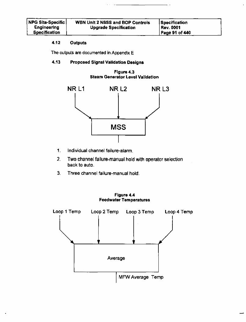
NPG Site-Specific WBN Unit 2 NSSS and BOP Controls SpecificationEngineering Upgrade Specification Rev. 0001Specification Page 91 of 440
4.12 Outputs
The outputs are documented in Appendix E
4.13 Proposed Signal Validation Designs
Figure 4.3Steam Generator Level Validation
NR L1 NR L2 NR L3
1. Individual channel failure-alarm.
2. Two channel failure-manual hold with operator selectionback to auto.
3. Three channel failure-manual hold.
Figure 4.4Feedwater Temperatures
Loop 1 Temp Loop 2 Temp Loop 3 Temp Loop 4 Temp
MFW Average Temp
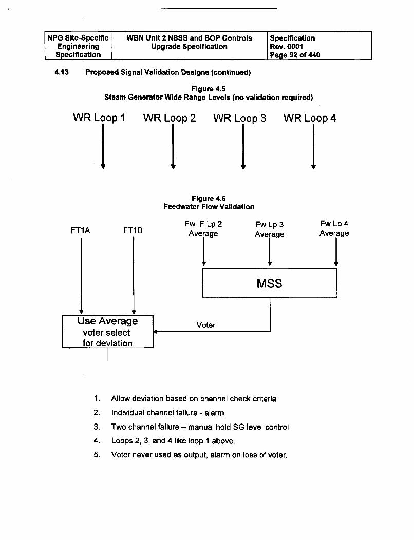
NPG Site-Specific WBN Unit 2 NSSS and BOP Controls SpecificationEngineering Upgrade Specification Rev. 0001Specification Page 92 of 440
4.13 Proposed Signal Validation Designs (continued)
Figure 4.5Steam Generator Wide Range Levels (no validation required)
WR Loop I
11WR Loop 2
1!WR Loop 3Ii WR Loop 4
IFigure 4.6
Feedwater Flow Validation
FT1A FT1 BFw F Lp 2 Fw Lip3Average Averge
tFw Lp 4Average
1.
2.
3.
4.
5.
Allow deviation based on channel check criteria.
Individual channel failure - alarm.
Two channel failure - manual hold SG level control.
Loops 2, 3, and 4 like loop I above.
Voter never used as output, alarm on loss of voter.
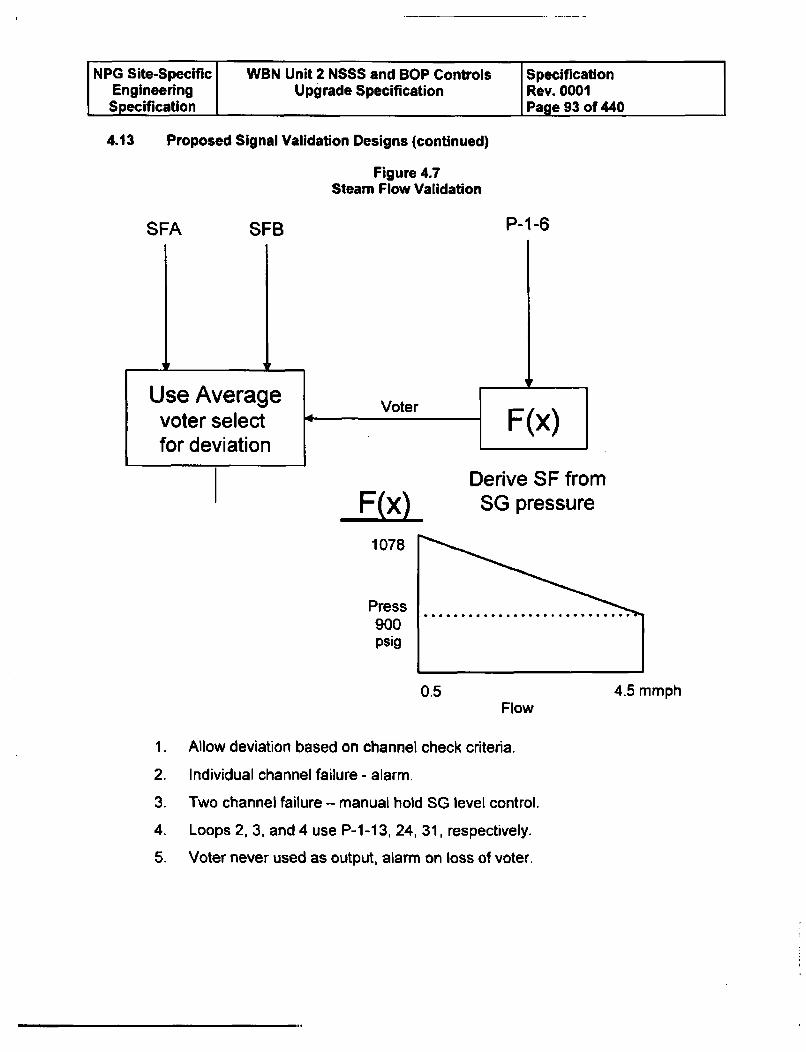
NPG Site-Specific WBN Unit 2 NSSS and BOP Controls SpecificationEngineering Upgrade Specification Rev. 0001Specification Page 93 of 440
4.13 Proposed Signal Validation Designs (continued)
Figure 4.7Steam Flow Validation
SFA SFB P-1-6
F
Use Averagevoter selectfor deviation
VoterF(x)
Derive SF from
E(X) SG pressure1078
Press900psig
0.5 4.5 mmphFlow
1.
2.
3.
4.
5.
Allow deviation based on channel check criteria.
Individual channel failure - alarm.
Two channel failure - manual hold SG level control.
Loops 2, 3, and 4 use P-1-1 3, 24, 31, respectively.
Voter never used as output, alarm on loss of voter.
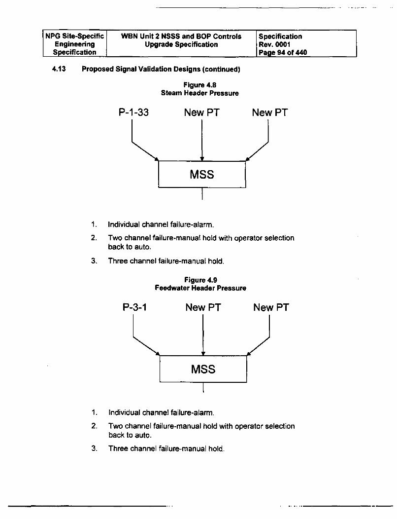
NPG Site-Specific WBN Unit 2 NSSS and BOP ControlsEngineering Upgrade SpecificationSpecification
4.13 Proposed Signal Validation Designs (continued)
Figure 4.8Steam Header Pressure
P-1-33 New PT
SpecificationRev. 0001Page 94 of 440
New PT
1.
2.
3.
Individual channel failure-alarm.
Two channel failure-manual hold with operator selectionback to auto.
Three channel failure-manual hold.
Figure 4.9Feedwater Header Pressure
P-3-1 New PT New PT
1.
2.
3.
Individual channel failure-alarm.
Two channel failure-manual hold with operator selectionback to auto.
Three channel failure-manual hold,
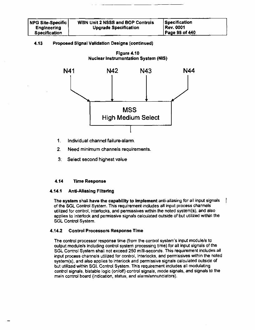
NPG Site-Specific WBN Unit 2 NSSS and BOP Controls SpecificationEngineering Upgrade Specification Rev. 0001Specification Page 95 of 440
4.13 Proposed Signal Validation Designs (continued)
Figure 4.10Nuclear Instrumentation System (NIS)
N41 N42 N43 N44
MSSHigh Medium Select
1. Individual channel failure-alarm.
2. Need minimum channels requirements.
3. Select second highest value
4.14 Time Response
4.14.1 Anti-Aliasing Filtering
The system shall have the capability to implement anti-aliasing for all input signalsof the SGL Control System. This requirement includes all input process channelsutilized for control, interlocks, and permissives within the noted system(s), and alsoapplies to interlock and permissive signals calculated outside of but utilized within theSGL Control System.
4.14.2 Control Processors Response Time
The control processor response time (from the control system's input module/s tooutput module/s including control system processing time) for all input signals of theSGL Control System shall not exceed 250 milli-seconds. This requirement includes allinput process channels utilized for control, interlocks, and permissives within the notedsystem(s), and also applies to interlock and permissive signals calculated outside ofbut utilized within SGL Control System. This requirement includes all modulatingcontrol signals, bistable logic (on/off) control signals, mode signals, and signals to themain control board (indication, status, and alarm/annunciators).
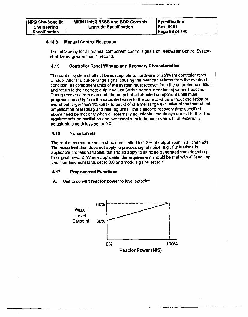
NPG Site-Specific WBN Unit 2 NSSS and BOP Controls SpecificationEngineering Upgrade Specification Rev. 0001Specification Page 96 of 440
4.14.3 Manual Control Response
The total delay for all manual component control signals of Feedwater Control Systemshall be no greater than 1 second.
4.15 Controller Reset Windup and Recovery Characteristics
The control system shall not be susceptible to hardware or software controller resetwindup. After the out-of-range signal causing the overload returns from the overloadcondition, all component units of the system must recover from the saturated conditionand return to their correct output values (within normal error limits) within 1 second.During recovery from overload, the output of all affected component units mustprogress smoothly from the saturated value to the correct value without oscillation orovershoot larger than 1% (peak to peak) of channel range exclusive of the theoreticalamplification of lead/lag and rate/lag units. The 1 second recovery time specifiedabove need be met only when all externally adjustable time delays are set to 0.0. Therequirements on oscillation and overshoot should be met even with all externallyadjustable time delays set to 0.0.
4.16 Noise Levels
The root mean square noise should be limited to 1.2% of output span in all channels.The noise limitation does not apply to process signal noise, e.g., fluctuations inapplicable process variables, but should apply to all noise generated from detectingthe signal onward. Where applicable, the requirement should be met with all lead, lag,and filter time constants set to 0.0 and module gains set to 1.
4.17 Programmed Functions
A. Unit to convert reactor power to level setpoint
WaterLevel
Setpoint 38% /
i
0% 100%
Reactor Power (NIS)
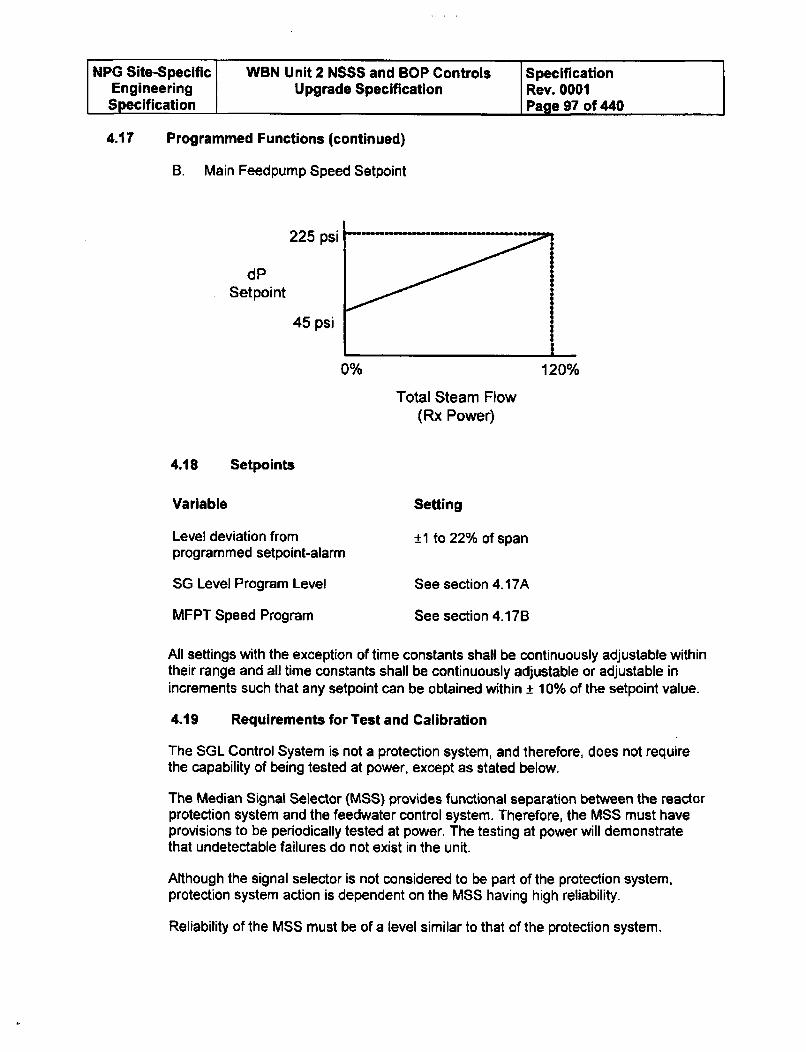
NPG Site-Specific WBN Unit 2 NSSS and BOP Controls SpecificationEngineering Upgrade Specification Rev. 0001Specification Page 97 of 440
4.17 Programmed Functions (continued)
B. Main Feedpump Speed Setpoint
225 psi
dPSetpoint
45 psi
.3-
0% 120%
Total Steam Flow(Rx Power)
4.18 Setpoints
Variable Setting
Level deviation fromprogrammed setpoint-alarm
SG Level Program Level
MFPT Speed Program
±1 to 22% of span
See section 4.17A
See section 4.17B
All settings with the exception of time constants shall be continuously adjustable withintheir range and all time constants shall be continuously adjustable or adjustable inincrements such that any setpoint can be obtained within ± 10% of the setpoint value.
4.19 Requirements for Test and Calibration
The SGL Control System is not a protection system, and therefore, does not requirethe capability of being tested at power, except as stated below.
The Median Signal Selector (MSS) provides functional separation between the reactorprotection system and the feedwater control system. Therefore, the MSS must haveprovisions to be periodically tested at power. The testing at power will demonstratethat undetectable failures do not exist in the unit.
Although the signal selector is not considered to be part of the protection system,protection system action is dependent on the MSS having high reliability.
Reliability of the MSS must be of a level similar to that of the protection system.
NPG Site-Specific WBN Unit 2 NSSS and BOP Controls SpecificationEngineering Upgrade Specification Rev. 0001Specification Page 98 of 440
4.20 Requirements for Associated Equipment
A. The time constant for all pressure (steam header and feedwater header) inputsensors (provided by others) of the Feedwater Control System shall notexceed 0.7 seconds. Inputs required to meet redundancy requirements shall besupplied by the Offerer.
B. The time constant for the turbine load input sensors (provided by others) of theFeedwater Control System shall not exceed 0.1 seconds. Inputs required tomeet redundancy requirements shall be supplied by the Offerer.
5.0 ROD CONTROL
6.1 System Description
The rod control system is composed of those control functions whose primary functionis to maintain the reactor coolant average temperature within an allowable deviation ofthe programmed reference temperature during steady state operation. In addition, thecontrol system causes the NSSS power to follow the turbine demand in a controlledfashion during load transients. Indicators are provided for monitoring systemoperation. Alarms and annunciators are provided to alert the plant operator of controlsystem malfunctions or abnormal operating conditions.
5.2 Rod Control System
The control scheme used to position the Control Rods is dependent on reactor powerlevel. Manual control of control rod position is used when the reactor thermal power isbetween 0% and 15%. Above 15% reactor thermal power, automatic control is used toposition the Control Rods to maintain the average reactor coolant temperature (Tavg)within +1- 3.5°F of the programmed average temperature (Tref) which is based uponplant load or Turbine impulse pressure. (Reference WBN N3-85-4001). Variousaverage reactor coolant temperature programs have their own particular advantagesand disadvantages. The following discussion indicates the considerations behind thechoice of the temperature program used for the nuclear plants.
The reactor control signal consists of an error signal used to direct rod speed andposition to automatically control reactor power. The two channels used to generate thetotal error signal are the deviation of the actual auctioneered (highest) primary coolanttemperature (Tavg) from the programmed average temperature (Tref) and themismatch between turbine load and nuclear power.
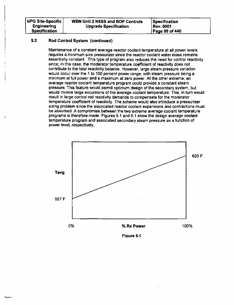
NPG Site-Specific WBN Unit 2 NSSS and BOP Controls SpecificationEngineering Upgrade Specification Rev. 0001Specification Page 99 of 440
5.2 Rod Control System (continued)
Maintenance of a constant average reactor coolant temperature at all power levelsrequires a minimum size pressurizer since the reactor coolant water mass remainsessentially constant. This type of program also reduces the need for control reactivitysince; in this case, the moderator temperature coefficient of reactivity does notcontribute to the total reactivity balance. However, large steam pressure variationwould occur over the 1 to 100 percent power range, with steam pressure being aminimum at full power and a maximum at zero power. At the other extreme, anaverage reactor coolant temperature program could provide a constant steampressure. This feature would permit optimum design of the secondary system, butwould involve large excursions of the average coolant temperature. This, in turn wouldresult in large control rod reactivity demands to compensate for the moderatortemperature coefficient of reactivity. The scheme would also introduce a pressurizersizing problem since the associated reactor coolant expansions and contractions mustbe absorbed. A compromise between the two extreme average coolant temperatureprograms is therefore made. Figures 5.1 and 5.1 show the design average coolanttemperature program and associated secondary steam pressure as a function ofpower level, respectively.
620 F
Tavg
557 F
0% % Rx Power 100%
Fioure 5.1
L_..
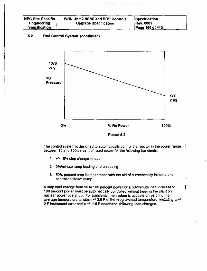
NPG Site-Specific WBN Unit 2 NSSS and BOP Controls SpecificationEngineering Upgrade Specification Rev. 0001Specification Page 100 of 440
5.2 Rod Control System (continued)
1078psig
SGPressure
900psig
0% % Rx Power 100%
Fioure 6.2
The control system is designed to automatically control the reactor in the power range Ibetween 15 and 100 percent of rated power for the following transients:
1. +/- 10% step change in load
2. 5%/minute ramp loading and unloading
3. 50% percent step load decrease with the aid of automatically initiated andcontrolled steam dump.
A step load change from 90 to 100 percent power or a 5%/minute load increase to100 percent power must be automatically controlled without tripping the plant onnuclear power overshoot. For transients, the system is capable of restoring theaverage temperature to within +/-3.5 F of the programmed temperature, including a +/-2 F instrument error and a +/- 1.5 F deadband, following load changes.
I
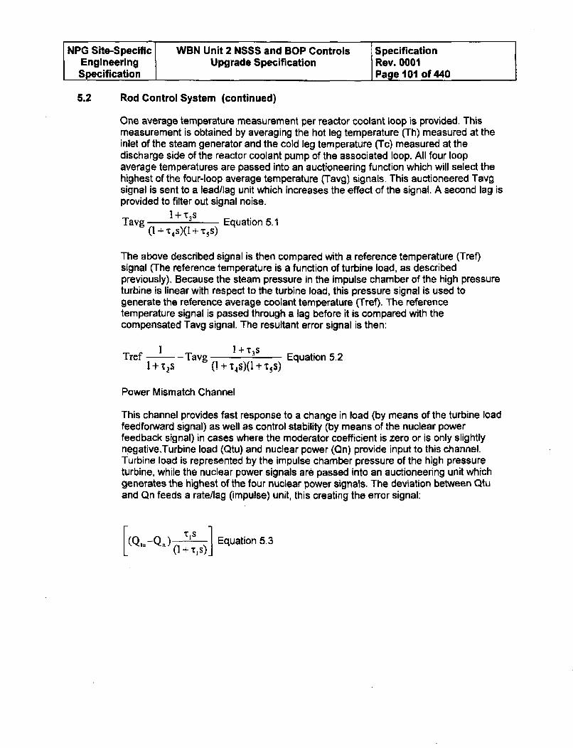
NPG Site-Specific WBN Unit 2 NSSS and BOP Controls SpecificationEngineering Upgrade Specification Rev. 0001Specification Page 101 of 440
5.2 Rod Control System (continued)
One average temperature measurement per reactor coolant loop is provided. Thismeasurement is obtained by averaging the hot leg temperature (Th) measured at theinlet of the steam generator and the cold leg temperature (Tc) measured at thedischarge side of the reactor coolant pump of the associated loop. All four loopaverage temperatures are passed into an auctioneering function which will select thehighest of the four-loop average temperature (Tavg) signals. This auctioneered Tavgsignal is sent to a lead/lag unit which increases the effect of the signal. A second lag isprovided to filter out signal noise.
Tavg 1 + x3s Equation 5.1(I + "C4S)(1 + c5s)
The above described signal is then compared with a reference temperature (Tref)signal (The reference temperature is a function of turbine load, as describedpreviously). Because the steam pressure in the impulse chamber of the high pressureturbine is linear with respect to the turbine load, this pressure signal is used togenerate the reference average coolant temperature (Tref). The referencetemperature signal is passed through a lag before it is compared with thecompensated Tavg signal. The resultant error signal is then:
I I + ________________Tref" - Tavg 1 Equation 5.2
I + '-2s (1 + '146)(1 + T. S)
Power Mismatch Channel
This channel provides fast response to a change in load (by means of the turbine loadfeedforward signal) as well as control stability (by means of the nuclear powerfeedback signal) in cases where the moderator coefficient is zero or is only slightlynegativeTurbine load (Qtu) and nuclear power (Qn) provide input to this channel.Turbine load is represented by the impulse chamber pressure of the high pressureturbine, while the nuclear power signals are passed into an auctioneering unit whichgenerates the highest of the four nuclear power signals. The deviation between Qtuand Qn feeds a rate/lag (impulse) unit, this creating the error signal:
(Q-Q)(1 +tis) Equation 5.3
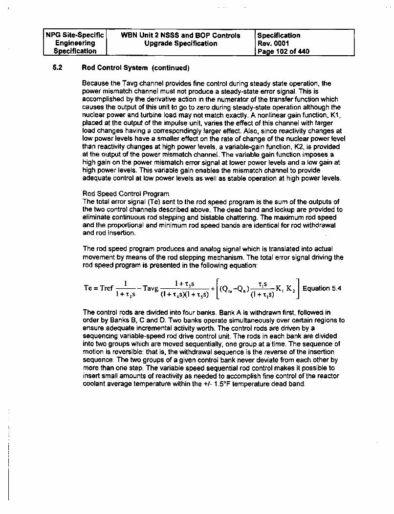
NPG Site-Specific WBN Unit 2 NSSS and BOP Controls SpecificationEngineering Upgrade Specification Rev. 0001Specification Page 102 of 440
5.2 Rod Control System (continued)
Because the Tavg channel provides fine control during steady state operation, thepower mismatch channel must not produce a steady-state error signal. This isaccomplished by the derivative action in the numerator of the transfer function whichcauses the output of this unit to go to zero during steady-state operation although thenuclear power and turbine load may not match exactly. A nonlinear gain function, KI,placed at the output of the impulse unit, varies the effect of this channel with largerload changes having a correspondingly larger effect. Also, since reactivity changes atlow power levels have a smaller effect on the rate of change of the nuclear power levelthan reactivity changes at high power levels, a variable-gain function, K2, is providedat the output of the power mismatch channel. The variable gain function imposes ahigh gain on the power mismatch error signal at lower power levels and a low gain athigh power levels. This variable gain enables the mismatch channel to provideadequate control at low power levels as well as stable operation at high power levels.
Rod Speed Control ProgramThe total error signal (Te) sent to the rod speed program is the sum of the outputs ofthe two control channels described above. The dead band and lockup are provided toeliminate continuous rod stepping and bistable chattering. The maximum rod speedand the proportional and minimum rod speed bands are identical for rod withdrawaland rod insertion.
The rod speed program produces and analog signal which is translated into actualmovement by means of the rod stepping mechanism. The total error signal driving therod speed program is presented in the following equation:
T=rf I Tag I+T 3s [ ____
Te =+Tref -Tavg - (Q-_Q.) t1 S K K2 Equation 5.4l+ rs (I +t 4s)(1 +Ts) ((1+'CIs) J
The control rods are divided into four banks. Bank A is withdrawn first, followed inorder by Banks B, C and D. Two banks operate simultaneously over certain regions toensure adequate incremental activity worth. The control rods are driven by asequencing variable-speed rod drive control unit. The rods in each bank are dividedinto two groups which are moved sequentially, one group at a time. The sequence ofmotion is reversible: that is, the withdrawal sequence is the reverse of the insertionsequence. The two groups of a given control bank never deviate from each other bymore than one step. The variable speed sequential rod control makes it possible toinsert small amounts of reactivity as needed to accomplish fine control of the reactorcoolant average temperature within the +1- 1.5°F temperature dead band.
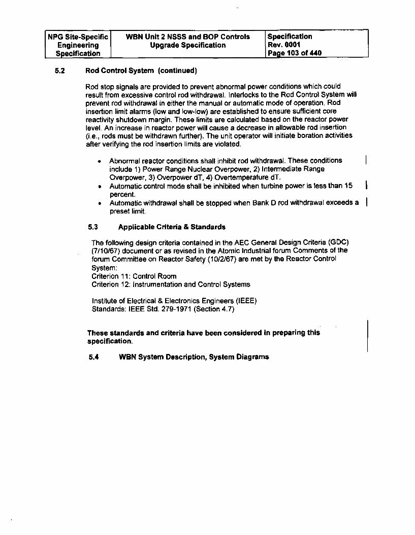
NPG Site-Specific WBN Unit 2 NSSS and BOP Controls SpecificationEngineering Upgrade Specification Rev. 0001Specification Page 103 of 440
5.2 Rod Control System (continued)
Rod stop signals are provided to prevent abnormal power conditions which couldresult from excessive control rod withdrawal. Interlocks to the Rod Control System willprevent rod withdrawal in either the manual or automatic mode of operation. Rodinsertion limit alarms (low and low-low) are established to ensure sufficient corereactivity shutdown margin. These limits are calculated based on the reactor powerlevel. An increase in reactor power will cause a decrease in allowable rod insertion(i.e., rods must be withdrawn further). The unit operator will initiate boration activitiesafter verifying the rod insertion limits are violated.
" Abnormal reactor conditions shall inhibit rod withdrawal. These conditionsinclude 1) Power Range Nuclear Overpower, 2) Intermediate RangeOverpower, 3) Overpower dT, 4) Overtemperature dT.
* Automatic control mode shall be inhibited when turbine power is less than 15percent.
* Automatic withdrawal shall be stopped when Bank D rod withdrawal exceeds apreset limit.
5.3 Applicable Criteria & Standards
The following design criteria contained in the AEC General Design Criteria (GDC)(7/10/67) document or as revised in the Atomic Industrial forum Comments of theforum Committee on Reactor Safety (10/2/67) are met by the Reactor ControlSystem:Criterion 11: Control RoomCriterion 12: Instrumentation and Control Systems
Institute of Electrical & Electronics Engineers (IEEE)Standards: IEEE Std. 279-1971 (Section 4.7)
These standards and criteria have been considered in preparing thisspecification.
5.4 WBN System Description, System Diagrams
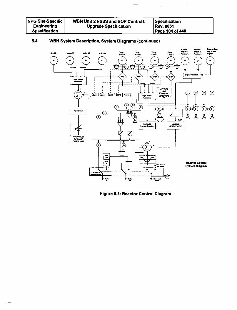
NPG Site-Specific WBN Unit 2 NSSS and BOP Controls SpecificationEngineering Upgrade Specification Rev. 0001Specification Page 104 of 440
5.4 WBN System Description, System Diagrams (continued)
TIwns Tuwbim OWN. tub
Ta18g, 1"g Two Iopg V-iso hop Plnal
Loop1 Lop 2 Loop a LOOP 4 Pý_ P " 8"1Ni PRI NO P12 NIS PRI Nis PRc
Figure 5.3: Reactor Control Diagram
NPG Site-Specific WBN Unit 2 NSSS and BOP Controls SpecificationEngineering Upgrade Specification Rev. 0001Specification Page 106 of 440
6.5 Indicators, Status Lights. and Controls
Main Control Room Controls
Controls shall be located in the Main Control Room to provide the unit operator fullcontrol of rod position. These controls shall allow the unit operator to establish eithermanual or automatic control mode and manually position any Control or ShutdownBank.
Main Control Room Indication
None for C&MS
5.6 Alarms and Annunciators
Main Control Room Annunciation
None for C&MS
5.7 Performance Limits
Verifications and Validations (V&V) of the following performance limits shall be acombination of the simulation analysis and testing (See WCAP-9159 for Plant SetpointStudy). The Offerer and TVA shall work together to determine how best to performthis V&V. Automatic control below 15% power is not required.
A. During Steady State conditions, the Rod Control system shall control Tavg towithin +/- 1.5F of programmed temperature.
B. The Rod Control system shall restore Tavg to within ± 3.5F of programmedtemperature, including a ± 2.0 F instrument error and a +/- 1.5F deadband forthe following design transients.
1. +/- 10% load step change
2. 5%/minute ramp loading and unloading
3. 50% step load decrease with the aid of automatically initiated and controlledsteam dump.
4. A step load change from 90 to 100% power or a 5%/minute ramp loadincrease to 100% power must be automatically controlled without trippingthe plant on nuclear power overshoot. The nuclear power overshoot mustbe limited to less than 3% power in conjunction with all instrumentuncertainties in the adverse direction.
NPG Site-Specific WBN Unit 2 NSSS and BOP Controls SpecificationEngineering Upgrade Specification Rev. 0001Specification Page 106 of 440
5.7 Performance Limits (continued)
C. If required, WBN Unit 1 "as found data" for open loop response times (step andramp inputs) for the existing control system shall be taken by TVA along withcontrol system field tuned settings. This performance data shall be factored intothe performance limit acceptance criteria. The control system open loopresponse is defined as the time delay from the change of process parameters tofinal output device response.
5.8 Specific Requirements
A. The system hardware must be designed with sufficient redundancy such that asingle failure of any critical system component or power supply will not result inthe loss of automatic functions or a spurious control output. In the event of acomplete automatic system failure due to multiple processor failures, etc., thesystem shall be designed to fail to manual control and hold all final controldevices at the position they held immediately before the failure.
B. Trend recording capability should be provided for any system input, output, or
control parameter. Selected trending shall have an archiving storage ability.
5.9 Accuracy
Channel accuracy is defined to include the accuracy of the primary element,transmitter, rack modules and any irocess or environmental effects on field mountedhardware. Rack environmental effects are not included in channel accuracy. Thecontrol accuracy is defined to include the channel accuracy plus the accuracy of anyisolators in the system, the controller accuracy and the actual environmental effects.Repeatability is defined as the closeness of agreement among repeatedmeasurements of the output for the same value of input, under normal operatingconditions over a short period of time (defined below), approaching an operating pointfrom a defined direction. Therefore, repeatability recognizes but does not include anyhysteresis non linearities in the system. The period of time over which the repeatabilityis defined is such that long term component drift is not included.
Accuracy Requirements for Normal and Abnormal Operating Conditions
The reactor control system should have control accuracy of ± 3.50 F for T(avg) - T(ref)deviation and control accuracy of ± 5.0°F for power mismatch. The repeatability of thereactor control system must be within ± 0.5 0F.
Digital processing reliability requirements are defined in Section 3.2.1.G.3.
Demanded rod speed deviation to actual ÷/- 2 steps/min rod speed

NPG Site-Specific WBN Unit 2 NSSS and BOP Controls SpecificationEngineering Upgrade Specification Rev. 0001Specification Page 107 of 440
5.9 Accuracy (continued)
The Tavg auctioneering function shall be capable of being tested at power operation.This function provides input to the Rod Speed Control signal used in the automaticcontrol mode. The Rod Bank Selector Switch can be placed in manual control modeduring the time period needed to perform any required testing of the Tavgauctioneering function.
5.10 Range
Tavg 530 to 630'F
Tref 530 to 6300F
Turbine impulse chamber Equivalent of 0 to 120% of maximum calculated turbine
pressure load
Neutron flux 0 to 120% of full power
Thot leg 530 to 6500F
Tcold leg 510 to 630°F
StII Inputs
Automatic control inputs
The inputs are documented in Appendix E
Auto/Manual Hand stations
The auto/manual handstations are show in Appendix F.
5.12 Outputs
The outputs are documented in Appendix E
5.13 Proposed Signal Validation Designs
1. The Nuclear Instrumentation System (NIS) input signals shall be provided with highselect auctioneering signal validation to conservatively control using the highestpower range value.
2. The NIS input signals shall be provided with input signal validation to prevent aninput failure high from resulting in a plant transient such as rate of changedetection.
3. The Loop Tavg input signals shall be provided with high select auctioneering signalvalidation to conservatively control using the highest Loop Tavg value.
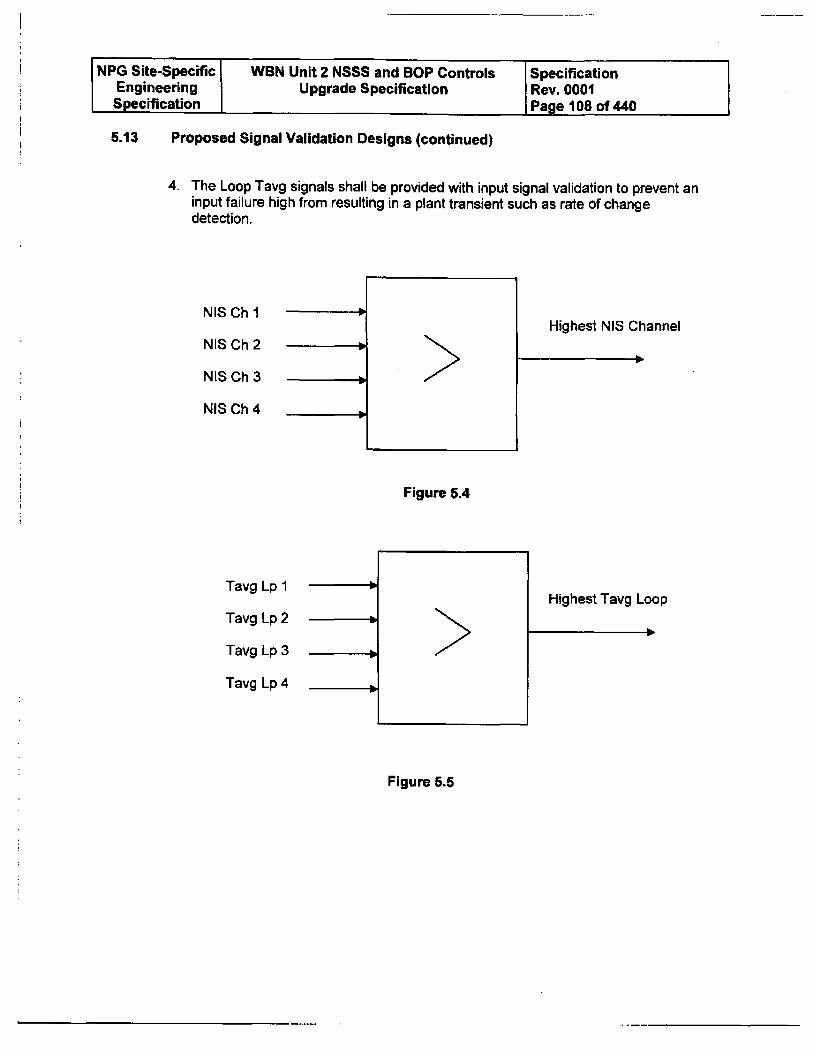
NPG Site-Specific WBN Unit 2 NSSS and BOP Controls SpecificationEngineering Upgrade Specification Rev. 0001Specification I Page 108 of 440
5.13 Proposed Signal Validation Designs (continued)
4. The Loop Tavg signals shall be provided with input signal validation to prevent aninput failure high from resulting in a plant transient such as rate of changedetection.
NIS Ch 1
NIS Ch 2
NIS Ch 3 1_
Highest NIS Channel
NIS Ch 4 3m
L_
Figure 5.4
Tavg Lp 1
Tavg Lp 2
Tavg Lp 3
Tavg Lp 4
Highest Tavg Loop
Figure 5.5
..........
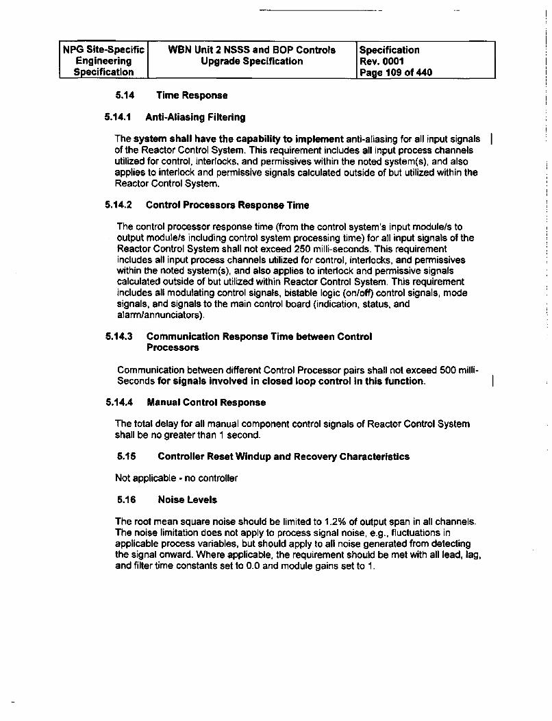
NPG Site-Specific WBN Unit 2 NSSS and BOP Controls SpecificationEngineering Upgrade Specification Rev. 0001Specification Page 109 of 440
5.14 Time Response
5.14.1 Anti-Aliasing Filtering
The system shall have the capability to implement anti-aliasing for all input signalsof the Reactor Control System. This requirement includes all input process channelsutilized for control, interlocks, and permissives within the noted system(s), and alsoapplies to interlock and permissive signals calculated outside of but utilized within theReactor Control System.
5.14.2 Control Processors Response Time
The control processor response time (from the control system's input module/s tooutput module/s including control system processing time) for all input signals of theReactor Control System shall not exceed 250 milli-seconds. This requirementincludes all input process channels utilized for control, interlocks, and permissiveswithin the noted system(s), and also applies to interlock and permissive signalscalculated outside of but utilized within Reactor Control System. This requirementincludes all modulating control signals, bistable logic (on/off) control signals, modesignals, and signals to the main control board (indication, status, andalarmlannunciators).
5.14.3 Communication Response Time between ControlProcessors
Communication between different Control Processor pairs shall not exceed 500 milli-
Seconds for signals involved in closed loop control in this function.
5.14.4 Manual Control Response
The total delay for all manual component control signals of Reactor Control Systemshall be no greater than 1 second.
5.15 Controller Reset Windup and Recovery Characteristics
Not applicable - no controller
5.16 Noise Levels
The root mean square noise should be limited to 1.2% of output span in all channels.The noise limitation does not apply to process signal noise, e.g., fluctuations inapplicable process variables, but should apply to all noise generated from detectingthe signal onward. Where applicable, the requirement should be met with all lead, lag,and filter time constants set to 0.0 and module gains set to 1.
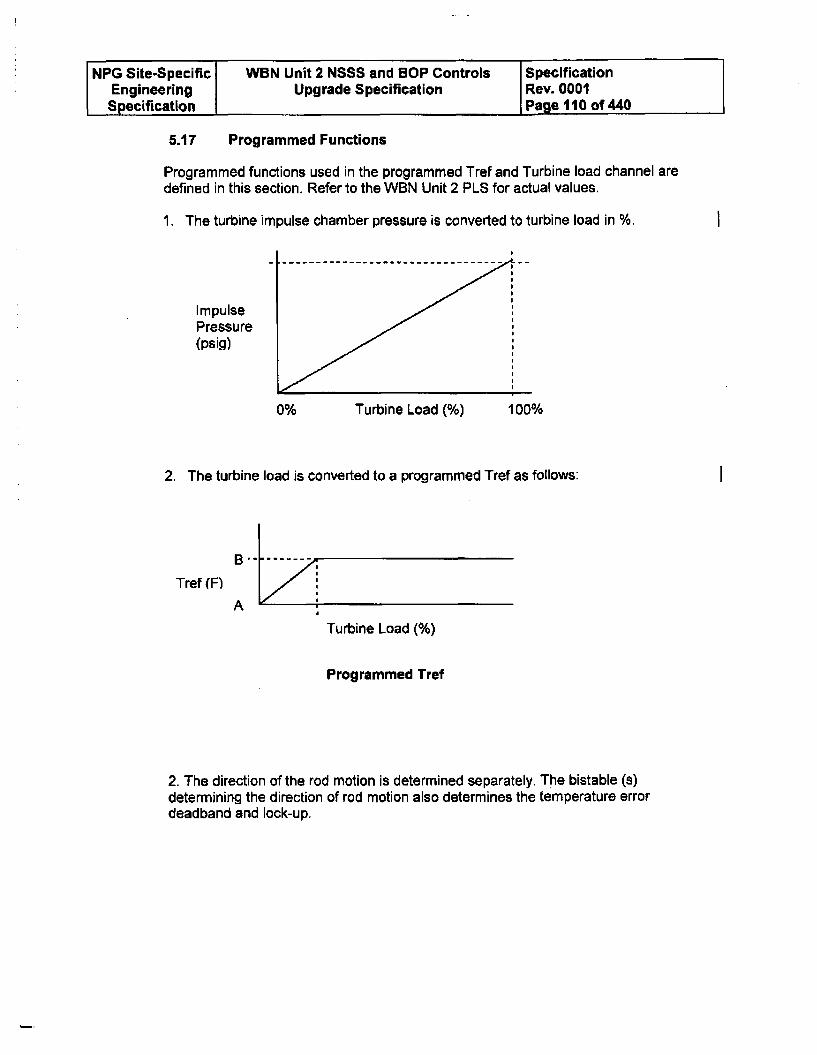
NPG Site-Specific WBN Unit 2 NSSS and BOP Controls SpecificationEngineering Upgrade Specification Rev. 0001Specification Page 110 of 440
5.17 Programmed Functions
Programmed functions used in the programmed Tref and Turbine load channel aredefined in this section. Refer to the WBN Unit 2 PLS for actual values.
1. The turbine impulse chamber pressure is converted to turbine load in %. I
ImpulsePressure(psig)
0% Turbine Load (%) 100%
2. The turbine load is converted to a programmed Tref as follows: I
Tref (F)
A
Turbine Load (%)
Programmed Tref
2. The direction of the rod motion is determined separately. The bistable (a)determining the direction of rod motion also determines the temperature errordeadband and lock-up.
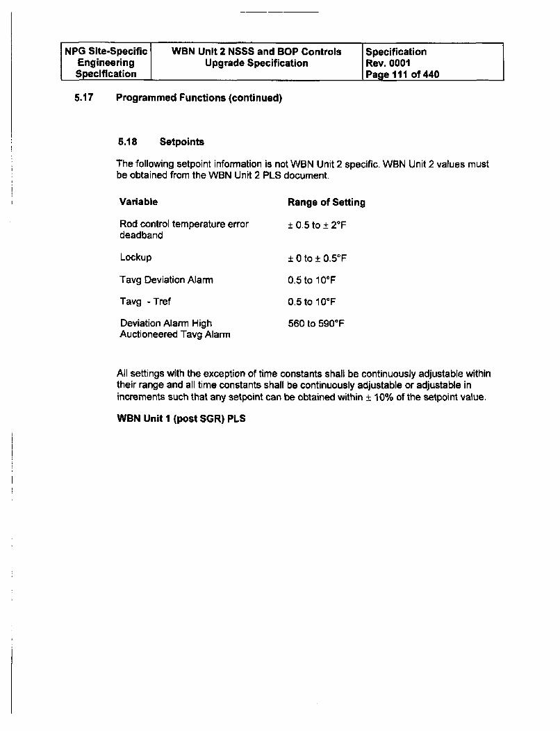
NPG Site-Specific WBN Unit 2 NSSS and BOP Controls SpecificationEngineering Upgrade Specification Rev. 0001Specification Page 111 of 440
5.17 Programmed Functions (continued)
5.18 Setpoints
The following setpoint information is not WBN Unit 2 specific. WBN Unit 2 values mustbe obtained from the WBN Unit 2 PLS document.
Variable Range of Setting
Rod control temperature errordeadband
Lockup
Tavg Deviation Alarm
Tavg - Tref
Deviation Alarm HighAuctioneered Tavg Alarm
± 0.5 to ± 20 F
± 0 to ± 0.5F
0.5 to 10°F
0.5 to 100 F
560 to 5900 F
All settings with the exception of time constants shall be continuously adjustable withintheir range and all time constants shall be continuously adjustable or adjustable inincrements such that any setpoint can be obtained within ± 10% of the setpoint value.
WBN Unit I (post SGR) PLS
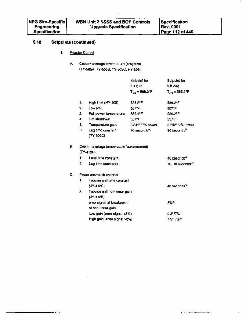
NPG Site-Specific WBN Unit 2 NSSS and BOP Controls SpecificationEngineering Upgrade Specification Rev. 0001Specification I Page 112 of 440
5.18 Setpoints (continued)
1. Reactor Control
A. Coolant average tempeialure (progrqan)
("Y-506A, TY-O5BB, TY-5OSC, HY-505)
1.
2.
3-4-
S.
6,
High limit (HY-505)
LOW n1itFull power temperature
Hot shuldown
Tomporature gain
Lag time constant
CTY. 505C)
Selpoint tar
full load
T,,4 M 588.20F
588.20F557F588.2 0F557*F0.3129171?% power30 s•sOnds'ls
Selpoint forfull load
T., = $S8.&2GF
588.21F5570F686.20F557'F0.?9gRFi% power30 secondst'
B. Coolant average temperature (auctoneered)
(TY-41P)
1. Lead timr constant2- Lag bmi constants
C. Power mrssmatch channel
1 Impulse unit time constant
(JY-412C)
P. Impulse unit non-linear gain
(JY-412B)
error signal at breakpoint
of non-linear gain
Low gain (error signal ,2%)
High gain (error signal >2%)
40 sOcOnrds-I10. 10 seconds
40 seconds:'•
5ep%$:.
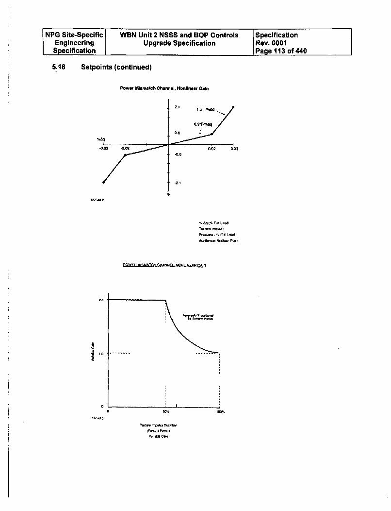
NPG Site-Specific WBN Unit 2 NSSS and BOP Controls SpecificationEngineering Upgrade Specification Rev. 0001Specification Page 113 of 440
5.18 Setpoints (continued)
Power Mlsmatch Channel, Nonlinear GaIr
2,1
OSTA4&q
0.02 0.03-0.6
-2.I
% a4 % PUG Load
TwomA Infukin
Ptamyo - % Foil Lind
E~[dffM PCtHANNEL_ NoDNLJPffiaM N
2.0
* ID
a
'WMA ~
SM., I bw
TurtijeIrw~ s *T~S~Climtnv
{Puvmrnt Powaf)VDniU 00.1
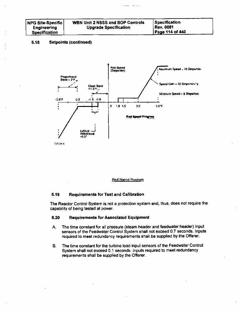
NPG Site-Specific VWBN Unit 2 NSSS and BOP Controls SpecificationEngineering Upgrade Specification Rev. 0001Specification Page 114 of 440
5.18 Setpoints (continued)
*1
(Steps~ln)
Band : 2
,,1..T _I II ea .B .n
Sptj O* = 32 Stepsftmin'r
Minimum Speed = 8 St9pep n
0 1.0 1.5 a.0 G"F
R" Spewd PrOgram
IQ
3,,.;•A 4
Rod Spoed Proara,
5.19 Requirements for Test and Calibration
The Reactor Control System is not a protection system and, thus, does not require thecapability of being tested at power.
6.20 Requirements for Associated Equipment
A. The time constant for all pressure (steam header and feedwater header) inputsensors of the Feedwater Control System shall not exceed 0.7 seconds. Inputsrequired to meet redundancy requirements shall be supplied by the Offerer.
B. The time constant for the turbine load input sensors of the Feedwater ControlSystem shall not exceed 0.1 seconds. Inputs required to meet redundancyrequirements shall be supplied by the Offerer.
NPG Site-Specific WBN Unit 2 NSSS and BOP Controls SpecificationEngineering Upgrade Specification Rev. 0001Specification Page 116 of 440
5.20 Requirements for Associated Equipment (continued)
6.0 STEAM DUMP CONTROL SYSTEM REQUIREMENTS
6.1 System Description
The condenser steam dump control system provides for automatic operation of thesteam dump valves following large turbine load reductions and reactor trips. Provisionis also made for remote manual control of steam pressure.
The steam dump control system performs the following functions:
1. Permits the nuclear plant to accept sudden large load decreases without a reactortrip.
2. Removes stored energy and residual heat following a reactor trip without actuationof the SG safety valves with the plant at equilibrium no-load conditions.
3. Permits a controlled cooldown to cold shutdown.
When the turbine-generator experiences a sudden, large electrical load reduction, theturbine control valves reduce steam flow to the turbine. The reactor control systemreceives a signal that the turbine demand has decreased and begins control rodinsertion to reduce the reactor energy output. Because the NSSS response time ismuch slower than the turbine response time, a large energy mismatch occurs. Thisenergy mismatch can quickly cause a large increase in RCS temperature and result ina reactor trip due to a parameter setpoint being exceeded. The steam dump systemprovides an artificial load for the reactor by dumping steam to the condenser (andatmosphere, in some instances). Dumping steam supplements the turbine load tomatch the reactor power level, thus avoiding excessive temperature rise in the RCS.
The steam dump system has 40% steam dump capacity to the condenser (i.e., 40% ofrated full load steam flow can be passed when all of the steam dump valves aredischarging steam). This allows the NSSS to withstand an external load step reductionof up to 50% of plant rated electrical load (10% NSSS load step capability plus 40%steam dump) without reactor trip or safety valve actuation.
These valves will also open under a sudden reduction in turbine-generator load (inexcess of 10%) or following a plant trip.
The steam dumps are also utilized in the pressure control mode during plant startupand cooldown. Prior to synchronizing the generator to the grid, the reactor power maybe increased up to 10% by dumping steam to the condenser. This will facilitateestablishing the minimum turbine-generator load (5-10%) without placing a step-loaddemand on the reactor. The dump valves close to compensate for the steam that isadmitted to the turbine. During plant cooldown, the condenser serves as a heat sink.
NPG Site-Specific WBN Unit 2 NSSS and BOP Controls SpecificationEngineering Upgrade Specification Rev. 0001Specification Page 116 of 440
6.2 Secondary Side Pressure Control System
This section defines two secondary side pressure control systems; the NSSSCondenser Steam Dump Control System and the BOP Atmospheric Dump ControlSystem.
6.2.1 Condenser Steam Dump Control System
The 3 functions specified in the previous section use 2 different modes of control, oneon Temperature Control (Tavg) and the other on Steam Pressure. The TemperatureControl (Tag) mode provides the valves with 2 different input signals, a trip open signalwhich will rapidly open the valves, and a modulate signal which will position thevalves. The Steam Pressure mode provides one type of input signal which is amodulate signal. This modulate signal will open or close the valve in 20 seconds,whereas the trip open signal will open the valve in 3 seconds. After the valve has beentrip opened, it will be modulated closed.
The condenser steam dump control system will prevent the valves from either beingtripped or modulated open whenever the condenser cannot accept the additionalsteam. The non-availability of the condenser is recognized by either high condenserback pressure or insufficient condenser cooling water (existence of an open circulatingwater circuit breaker, 1 out of 3 open)
The condenser steam dump system functional tasks are:
a. Temperature Control (T.v) - Control of reactor coolant system averagetemperature (Tavg)
b. Pressure Control - Control of steam pressure.
The temperature control mode (Tav) is commonly referred to as automatic control,with pressure control being considered as manual. A brief description of these controlmodes is given below. Figure 6.4 is a block diagram of the control system for thecondenser steam dump valves.
NPG Site-Specific WBN Unit 2 NSSS and BOP Controls SpecificationEngineering Upgrade Specification Rev. 0001Specification Page 117 of 440
6.2.1 Condenser Steam Dump Control System (continued)
A. Temperature Control (Tsvg)
The measured RCS Ta.g is used as the control parameter in this mode. Figure 6.2illustrates a program which relates Tavg to NSSS power level. To operate at a givenpower level, the reactor rod control system inserts or withdraws control rods toobtain a T.agwhich corresponds to the programmed Tref. The Westinghouse NSSSemploys a load-follow control system. The reactor responds to turbine-generatorload changes - so the reference temperature (Trf) which corresponds to the actualload is compared to Ta8 g The resultant temperature error is used to increase ordecrease the NSSS load. Operation of the reactor rod control system is simplyillustrated in Figure 6.2, and is described below. Assume that the turbine-generatoris operating at 100% rated load. The turbine impulse pressure corresponds topoint L. This pressure signal is converted into a Tref signal which corresponds topoint H. The reactor rod control system will adjust the reactor control rods until Tavois equal to or approximately equal to Tref. Now assume that the turbine-generatorload is suddenly reduced to 50% rated load. Turbine impulse pressure changesfrom point L to K, which causes Trf to change from point H to G. A large differencenow exists between the values of Tevq (at point D) and Tref (at point G). Thisdifference is referred to as the error signal and is used to adjust the reactor controlrod position. In the assumed situation, the control rods insert into the reactor coreto reduce reactor power until T3 v9 was again equal to Tref. Functional tasksperformed by the steam dump system under the temperature control modeinclude:
1. Load rejection - Reduction in the turbine impulse pressure signal indicates theoccurrence of load loss. If the load loss is greater than 10%, steam dumpvalves are actuated. The number of valves which open is determined by themagnitude of load loss. As Tavg approaches Tref, the valves are modulatedclosed. The steam dump flow reduction is as fast as rod cluster controlassemblies are capable of inserting negative reactivity.
NPG Site-Specific WBN Unit 2 NSSS and BOP Controls SpecificationEngineering Upgrade Specification Rev. 0001Specification Page 118 of 440
6.2.1 Condenser Steam Dump Control System (continued)
A turbine impulse pressure signal is supplied to the steam dump control systemto determine if a load loss has actually occurred. The signal serves as input tothe tcs unit. The output of this unit goes to a bistable which, associated
I + tIS
with logic and interlock circuits, control the air supplies to the dump valves. Thebistable setting will be such that no steam dump valves are enabled for loadlosses less than 10%, and all valve banks are enabled for load losses greaterthan 10%. The signals controlling the air supplies to the steam dump valves areinterlocked such that the air supplies are blocked on low reactor coolant systemtemperature or if the condenser is not available. Assuming a load rejection hasoccurred and that the air supply to the dump valves has been enabled, thereactor coolant average temperature is employed to determine the position ofthe dump valves. The measured auctioneered reactor coolant average
temperature goes to the ]+ 112s unit, the output of which is compared to theI + -CBS
reference temperature determined by turbine load (impulse pressure).Following a sudden load decrease, Tref is decreased, thus rapidly creating anerror signal. This signal goes to 2 bistable functions which, with theirassociated logic, determine the positions of the solenoids that bypass the dumpvalve positioners. Each bistable function trips open one bank of dump valves.The error signal is also used to modulate the valves open and Glosed throughthe valve positioners.
2. Plant trip - On receipt of the reactor trip signal, Ta%9 is compared to no-load Trot(point E on Figure 6.2), and the appropriate number of steam dump valves aretripped open or modulated open. The temperature error signal is used tomodulate the appropriate banks of dump valves open and closed until Tavgequals Trot.Following a plant trip as determined by a turbine trip signal, the loss of load(load rejection) steam dump control is defeated and the plant trip steam dumpcontrol is employed. The turbine trip signal enables air to be supplied to the 2banks of dump valves. The measured auctioneered reactor coolant average
I + t1 2 Stemperature goes to the I + x;s unit, the output of which is compared to the noI + z3
load reference temperature. The error signal goes to 2 bistable functions which,with their logic, determine the positions of the solenoids that bypass the dumpvalve positioners. Each bistable function trips open one bank of dump valves.Through the valve positioners, the error signal is also used to modulate thevalves open and closed.
NPG Site-Specific WBN Unit 2 NSSS and BOP Controls SpecificationEngineering Upgrade Specification Rev. 0001Specification Page 119 of 440
6.2.1 Condenser Steam Dump Control System (continued)
3. Quick open feature - This feature exists only in the temperature control modeduring either load rejection (I) or reactor trip (2). In the event of a suddenincrease in RCS Tavto above controller determined set points bi-stableswitches trip open the steam dump valves. On an increase in Tavg above acontroller determined Hi Tag error signal, the first two banks of dump valvesare automatically tripped open. On an increase in Ta. above a Hi-Hi Tg errorsignal, the remaining two banks of dump valves are opened.
B. Pressure Control
Main steam header pressure is the parameter used to modulate steam dumpvalves to maintain, or change, steam pressure. The rod control system is designedto automatically control the reactor power range between 15% and 100% of ratedpower and to accept the following transients without reactor trip:
a. Plus or minus 10% step change in load.
b. 5% per minute ramp load increase or decrease.
That is, the reactor power is automatically adjusted to accept these load transientswithout exceeding operating parameter setpoints which would trip the reactor.When load reductions which exceed the capabilities of the automatic controlsystem described above occur, a reactor trip will occur if provisions are not madeto limit the changes in the operating parameter. This capability is provided by thesteam dump system which dissipates the heat energy difference between thereactor output and that delivered to the turbine, thereby limiting heatup of the RCS.
Functional tasks performed under the pressure control mode are:
1. Maintain hot standby - The steam header pressure to be maintained constantby modulating the dump valves. Steam header pressure is used in aproportional plus integral control function to supply a modulating signal to thecondenser dump valves.
2. Maintain stable primary plant condition - Turbine-generator operatingprocedures typically require the prompt addition of 5% to 10% of ratedelectrical load after synchronizing the unit to the grid. Prior to synchronizing,the NSSS thermal power level is increased to a value commensurate with theminimum electrical load. The steam dump system pressure control mode isselected to maintain stable primary plant conditions when the step load changein turbine power occurs during synchronization to the grid, after which thecontrol is switched to the temperature control mode previously described.
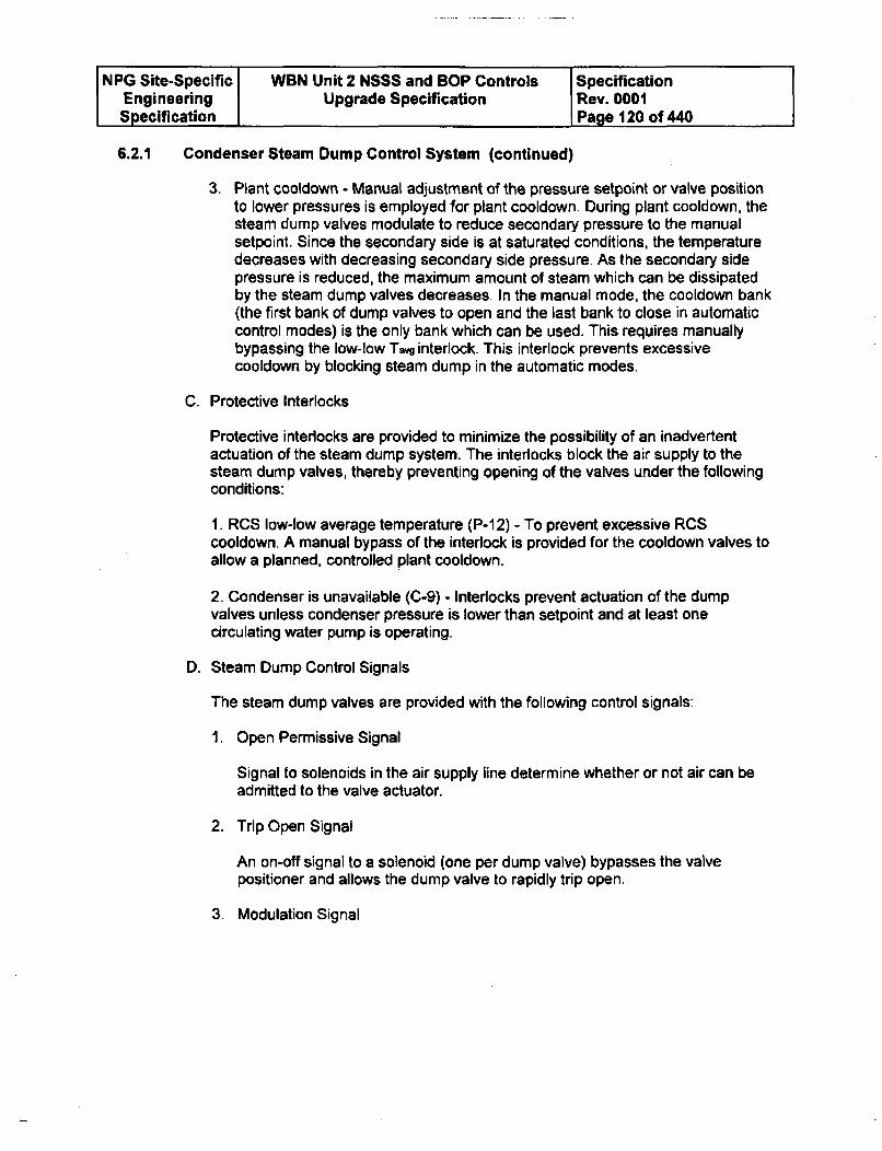
NPG Site-Specific WBN Unit 2 NSSS and BOP Controls SpecificationEngineering Upgrade Specification Rev. 0001Specification Page 120 of 440
6.2.1 Condenser Steam Dump Control System (continued)
3. Plant cooldown - Manual adjustment of the pressure setpoint or valve positionto lower pressures is employed for plant cooldown. During plant cooldown, thesteam dump valves modulate to reduce secondary pressure to the manualsetpoint. Since the secondary side is at saturated conditions, the temperaturedecreases with decreasing secondary side pressure. As the secondary sidepressure is reduced, the maximum amount of steam which can be dissipatedby the steam dump valves decreases. In the manual mode, the cooldown bank(the first bank of dump valves to open and the last bank to close in automaticcontrol modes) is the only bank which can be used. This requires manuallybypassing the low-low Tavg interlock. This interlock prevents excessivecooldown by blocking steam dump in the automatic modes.
C. Protective Interlocks
Protective interlocks are provided to minimize the possibility of an inadvertentactuation of the steam dump system. The interlocks block the air supply to thesteam dump valves, thereby preventing opening of the valves under the followingconditions:
1. RCS low-low average temperature (P-1 2) - To prevent excessive RCScooldown. A manual bypass of the interlock is provided for the cooldown valves toallow a planned, controlled plant cooldown.
2. Condenser is unavailable (C-9) - Interlocks prevent actuation of the dumpvalves unless condenser pressure is lower than setpoint and at least onecirculating water pump is operating.
D. Steam Dump Control Signals
The steam dump valves are provided with the following control signals:
1. Open Permissive Signal
Signal to solenoids in the air supply line determine whether or not air can beadmitted to the valve actuator.
2. Trip Open Signal
An on-off signal to a solenoid (one per dump valve) bypasses the valvepositioner and allows the dump valve to rapidly trip open.
3. Modulation Signal
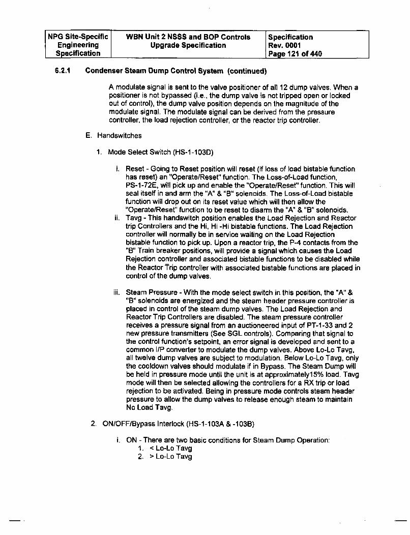
NPG Site-Specific WBN Unit 2 NSSS and BOP Controls SpecificationEngineering Upgrade Specification Rev. 0001Specification Page 121 of 440
6.2.1 Condenser Steam Dump Control System (continued)
A modulate signal is sent to the valve positioner of all 12 dump valves. When apositioner is not bypassed (i.e., the dump valve is not tripped open or lockedout of control), the dump valve position depends on the magnitude of themodulate signal. The modulate signal can be derived from the pressurecontroller, the load rejection controller, or the reactor trip controller.
E. Handswitches
1. Mode Select Switch (HS-I-103D)
i. Reset - Going to Reset position will reset (if loss of load bistable functionhas reset) an "Operate/Reset" function. The Loss-of-Load function,PS-1-72E, will pick up and enable the "Operate/Reset" function. This willseal itself in and arm the "A" & "B" solenoids. The Loss-of-Load bistablefunction will drop out on its reset value which will then allow the"Operate/Reset" function to be reset to disarm the "A" & "B" solenoids.
ii. Tavg - This handswitch position enables the Load Rejection and Reactortrip Controllers and the Hi, Hi -Hi bistable functions. The Load Rejectioncontroller will normally be in service waiting on the Load Rejectionbistable function to pick up. Upon a reactor trip, the P-4 contacts from the"B" Train breaker positions, will provide a signal which causes the LoadRejection controller and associated bistable functions to be disabled whilethe Reactor Trip controller with associated bistable functions are placed incontrol of the dump valves.
iii. Steam Pressure - With the mode select switch in this position, the "A" &"B" solenoids are energized and the steam header pressure controller isplaced in control of the steam dump valves. The Load Rejection andReactor Trip Controllers are disabled. The steam pressure controllerreceives a pressure signal from an auctioneered input of PT-1 -33 and 2new pressure transmitters (See SGL controls). Comparing that signal tothe control function's setpoint, an error signal is developed and sent to acommon I/P converter to modulate the dump valves. Above Lo-Lo Tavg,all twelve dump valves are subject to modulation. Below Lo-Lo Tavg, onlythe cooldown valves should modulate if in Bypass. The Steam Dump willbe held in pressure mode until the unit is at approximately15% load. Tavgmode will then be selected allowing the controllers for a RX trip or loadrejection to be activated. Being in pressure mode controls steam headerpressure to allow the dump valves to release enough steam to maintainNo Load Tavg.
2. ON/OFF/Bypass Interlock (HS-1-103A &-103B)
i. ON - There are two basic conditions for Steam Dump Operation:1. < Lo-Lo Tavg2. > Lo-Lo Tavg
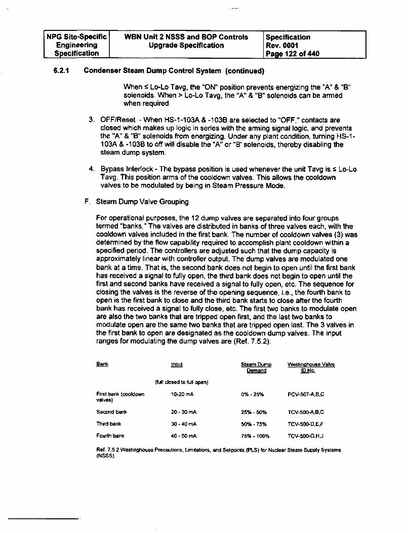
NPG Site-Specific WBN Unit 2 NSSS and BOP Controls SpecificationEngineering Upgrade Specification Rev. 0001Specification Page 122 of 440
6.2.1 Condenser Steam Dump Control System (continued)
When s Lo-Lo Tavg, the "ON" position prevents energizing the "A" & "B"solenoids. When > Lo-Lo Tavg, the "A" & "B" solenoids can be armedwhen required
3. OFF/Reset - When HS-1-103A & -103B are selected to "OFF," contacts areclosed which makes up logic in series with the arming signal logic, and preventsthe "A" & "B" solenoids from energizing. Under any plant condition, turning HS-1-103A & -103B to off will disable the "A" or "B' solenoids, thereby disabling thesteam dump system.
4. Bypass Interlock - The bypass position is used whenever the unit Tavg is s Lo-LoTavg. This position arms of the cooldown valves. This allows the cooldownvalves to be modulated by being in Steam Pressure Mode.
F. Steam Dump Valve Grouping
For operational purposes, the 12 dump valves are separated into four groupstermed "banks." The valves are distributed in banks of three valves each, with thecooldown valves included in the first bank. The number of cooldown valves (3) wasdetermined by the flow capability required to accomplish plant cooldown within aspecified period. The controllers are adjusted such that the dump capacity isapproximately linear with controller output. The dump valves are modulated onebank at a time. That is, the second bank does not begin to open until the first bankhas received a signal to fully open, the third bank does not begin to open until thefirst and second banks have received a signal to fully open, etc. The sequence forclosing the valves is the reverse of the opening sequence, i.e., the fourth bank toopen is the first bank to close and the third bank starts to close after the fourthbank has received a signal to fully close, etc. The first two banks to modulate openare also the two banks that are tripped open first, and the last two banks tomodulate open are the same two banks that are tripped open last. The 3 valves inthe first bank to open are designated as the cooldown dump valves. The inputranges for modulating the dump valves are (Ref. 7.5.2):
Bank input Steam Dump Westinghouse Valve
Demand ID No.
(full closed to full open)
First bank (cooldown 10-20 mA 0% - 25% PCV-507-A.B.Cvalves)
Second bank 20 - 30 mA 25% - 50% TCV-500-A.B.C
Third bank 30 - 40 mA 50% - 75% TCV-500-D.E.F
Fourth bank 40 - 50 mA 75%- 100% TCV-500-G.H,J
Ref. 7.5.2 Westinghouse Precautions, Limitations, and Setpoints (PLS) for Nuclear Steam Supply Systems(NSSS).
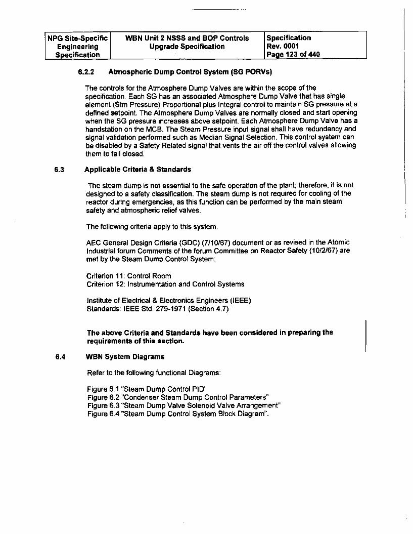
NPG Site-Specific WBN Unit 2 NSSS and BOP Controls SpecificationEngineering Upgrade Specification Rev. 0001Specification Page 123 of 440
6.2.2 Atmospheric Dump Control System (SG PORVs)
The controls for the Atmosphere Dump Valves are within the scope of thespecification. Each SG has an associated Atmosphere Dump Valve that has singleelement (Stm Pressure) Proportional plus Integral control to maintain SG pressure at adefined setpoint. The Atmosphere Dump Valves are normally closed and start openingwhen the SG pressure increases above setpoint. Each Atmosphere Dump Valve has ahandstation on the MCB. The Steam Pressure input signal shall have redundancy andsignal validation performed such as Median Signal Selection. This control system canbe disabled by a Safety Related signal that vents the air off the control valves allowingthem to fail closed.
6.3 Applicable Criteria & Standards
The steam dump is not essential to the safe operation of the plant; therefore, it is notdesigned to a safety classification. The steam dump is not required for cooling of thereactor during emergencies, as this function can be performed by the main steamsafety and atmospheric relief valves.
The following criteria apply to this system.
AEC General Design Criteria (GDC) (7/10/67) document or as revised in the AtomicIndustrial forum Comments of the forum Committee on Reactor Safety (1012/67) aremet by the Steam Dump Control System:
Criterion 11: Control RoomCriterion 12: Instrumentation and Control Systems
Institute of Electrical & Electronics Engineers (IEEE)Standards: IEEE Std. 279-1971 (Section 4.7)
The above Criteria and Standards have been considered in preparing the
requirements of this section.
6.4 WBN System Diagrams
Refer to the following functional Diagrams:
Figure 6.1 "Steam Dump Control PID"Figure 6.2 "Condenser Steam Dump Control Parameters"Figure 6.3 "Steam Dump Valve Solenoid Valve Arrangement"Figure 6.4 "Steam Dump Control System Block Diagram".
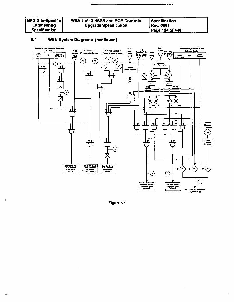
NPG Site-Specific WBN Unit 2 NSSS and BOP Controls SpecificationEngineering Upgrade Specification Rev. 0001Specification Page 124 of 440
6.4 WBN System Diagrams (continued)
Figure 6.1
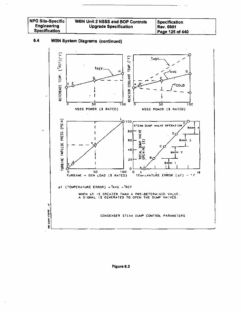
NPG Site-Specific I WBN Unit 2 NSSS and BOP Controls SpecificationEngineering I Upgrade Specification Rev. 0001Specification j Page 125 of 440
6.4 WBN System Diagrams (continued)
La~
1~~Li
0~
IL'I-
LUC)zLU
La)
LU
NSSS POWER (Z RATED)
Li,
InLfl
U)CA
ca-
cc
0 50TURBINE - GEN LOAD
al (TEMPERATURE ERROR)
WHEN AT IS GREATER THAN A PRE-DETERMINED VALUE.A SIGNAL IS GENERATED TO OPEN THE DUMP VALVES.
p
CONDENSER STEAM DUMP CONTROL PARAMETERS
Figure 6.2
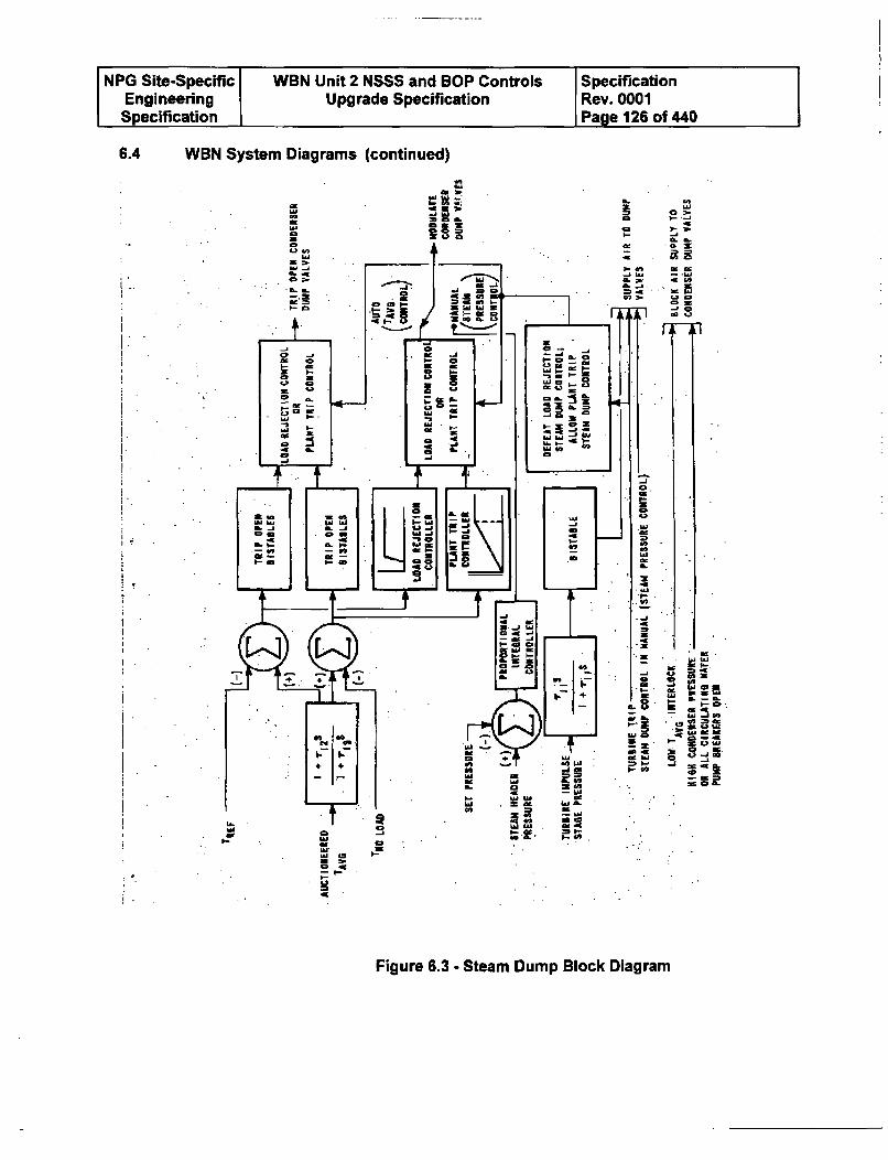
NPG Site-Specific WBN Unit 2 NSSS and BOP Controls SpecificationEngineering Upgrade Specification Rev. 0001Specification Page 126 of 440
6.4 WBN System Diagrams (continued)
a
a
a0C
o,..- a..--. 3- ~
* I- a
a b
C. n-4 ISn a a
I!!0
C[
Sn..
'ao ~,- .~ja,- ~.a. a.
.0-s
MI C* a-. 'aa
* a* ala
o =
a e
TI
I.,
I..11
SI- .2ia .
=j M
w.
SMa
Is-.4
a-CC
CI-
Figure 6.3 - Steam Dump Block Diagram
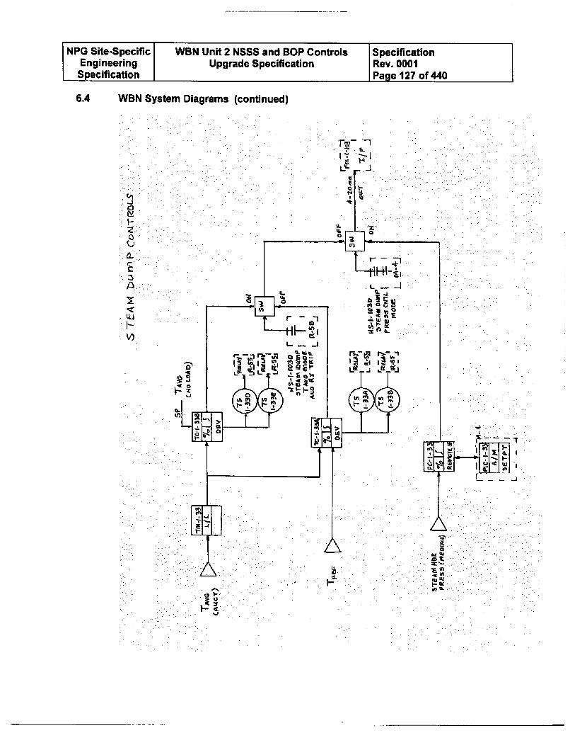
NPG Site-Specific WBN Unit 2 NSSS and BOP Controls SpecificationEngineering Upgrade Specification Rev. 0001Specification Page 127 of 440
6.4 WBN System Diagrams (continued)
.4C
1-z0U0~
H-all
'~~1a
*Th-fl.1-; .- 1
LiL 4.3-.
LJ
Mill-
*jL~'', . ,
,..-
1-
A1SULccCL
NPG Site-Specific WBN Unit 2 NSSS and BOP Controls SpecificationEngineering Upgrade Specification Rev. 0001Specification Page 128 of 440
6.4 WBN System Diagrams (continued)
Figure 6.4 - Steam Dump Detail Diagram
6.5 Indicators, Status Lights, and Controls
The control system will provide a signal for MCB indication of the magnitude of thesignal used to modulate the dump valves.
Main Control Room Controls
Steam Dump Control Mode 3 Position Switch
A three position switch on the MCB will input into the control system for the selectionof the mode of steam dump control.
The switch positions are: RESET (Momentary and spring return to Tavg)TAVGSTEAM PRESS
Steam Dump Control Interlock 3 Position Switch
A three position switch on the MCB will input into the control system for the manualbypass of the low temperature interlock. The bypass must be momentary contact only.
The required positions are: OFF (Reset Tavg Bypass)ONBYPASS INTERLOCK (Momentary and springreturn to ON)
Manual control of the steam header pressure controller setpoint is provided on theMCB.
The control system will provide digital outputs for MCB status indication of permissiveand interlock circuits C-7 and C-9 on the MCB.
The control system will provide digital outputs for MCB status indication of the bypassof the low-low T(avg) interlock (P-12).
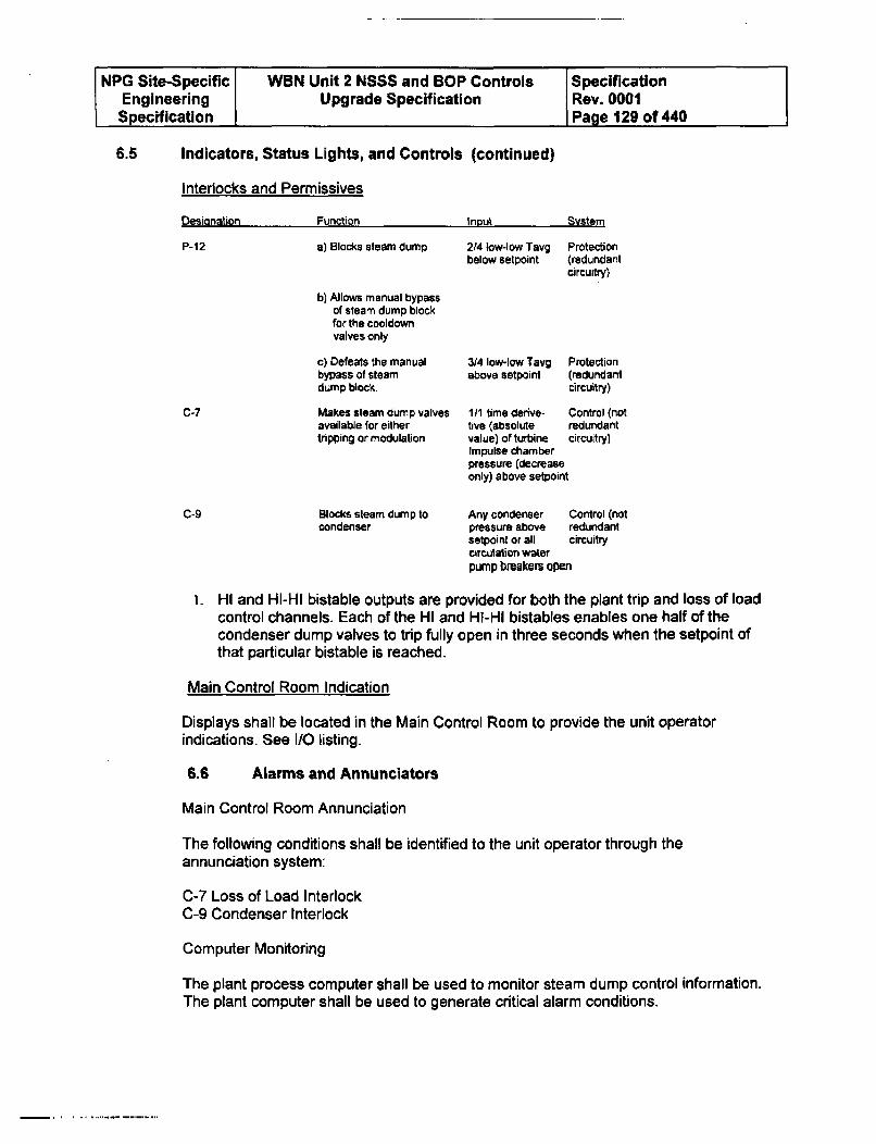
NPG Site-Specific WBN Unit 2 NSSS and BOP Controls SpecificationEngineering Upgrade Specification Rev. 0001Specification Page 129 of 440
6.5 Indicators, Status Lights, and Controls (continued)
Interlocks and Permissives
nC% L, ian Ci= n--n I Q +_M Y., M. LU
P-12 a) Blocks steam dump
b) Allows manual bypassof steam dump blockfor the cooldownvalves only
c) Defeats the manualbypass of steamdump block.
Makes steam dump valvesavailable for eithertripping or modulation
Blocks steam dump tocondenser
2/4 low-low Tavgbelow setpoint
Protection(redundantcircuitry)
C-7
C-9
3/4 low-low Tavg Protectionabove setpoint (redundant
circuitry)
1/1 time derive- Control (notfive (absolute redundantvalue) of turbine circuitry)Impulse chamberpressure (decreaseonly) above setpoint
Any condenser Control (notpressure above redundantsetpoint or all circuitrycirculation waterpump breakers open
i. HI and HI-HI bistable outputs are provided for both the plant trip and loss of loadcontrol channels. Each of the HI and Hi-HI bistables enables one half of thecondenser dump valves to trip fully open in three seconds when the setpoint ofthat particular bistable is reached.
Main Control Room Indication
Displays shall be located in the Main Control Room to provide the unit operatorindications. See I/O listing.
6.6 Alarms and Annunciators
Main Control Room Annunciation
The following conditions shall be identified to the unit operator through theannunciation system:
C-7 Loss of Load Interlock
C-9 Condenser Interlock
Computer Monitoring
The plant process computer shall be used to monitor steam dump control information.The plant computer shall be used to generate critical alarm conditions.
NPG Site-Specific WBN Unit 2 NSSS and BOP Controls SpecificationEngineering Upgrade Specification Rev. 0001Specification Page 130 of 440
6.7 Performance Limits
Verifications and Validations (V&V) of the following performance limits shall be acombination of the simulation analysis and testing (See WCAP-91 59 for Plant SetpointStudy). The Offerer and TVA shall work together to determine how best to performthis V&V. Automatic control below 15% power is not required.
A. For a 50% load reduction, the Load Rejection Controller in conjunction with theRod Control System must: 1) Prevent a Reactor trip and 2) Prevent actuation ofthe SG Safety Valves.
B. For a Plant or Turbine Trip from 100% power, the Plant Trip Controller inconjunction with the Rod Control System must; 1) Prevent actuation of the SGSafety Valves and to minimize secondary and primary transients and 2) Resultin a RCS Overcooling transient where Tavg drops below XXXF or Loss ofShutdown Margin.
C. If required, WBN Unit 1 "as found data" for open loop response times (step andramp inputs) for the existing control system shall be taken by TVA along withcontrol system field tuned settings. This performance data shall be factored intothe performance limit acceptance criteria. The control system open loopresponse is defined as the time delay from the change of process parameters tofinal output device response.
6.8 Specific Requirements
Design Failure Modes
Inadvertent opening of the dump valves can result in a plant trip or an uncontrolledcooldown. Therefore, the steam dump valves are high quality valves structurallyarranged for energize-to-open operation and fail closed on loss of air pressure or lossof signal. In addition, redundant solenoid valves are provided to vent the actuating airwhen a block signal is transmitted to the valve from the protection system.
Control System Segmentation
The steam dump control system shall be segmented from the Steam Generator Levelcontrol system and the Rod Control System so that a failure/software problem in asingle processor pair will not result in an overcooling transient as analyzed in theWBN Chapter 15 Safety Analysis such as SGL control valves failing open, Rodsinserting, and Condenser Dump valves failing open concurrently. In addition, thesteam dump control system shall be segmented from the Atmospheric Dump controlsystem so that a failure/software problem in a single processor pair will not: 1) preventat least one of the systems from operating thus protecting the SG Safety valves fromopening; and 2) cause spurious opening of both Condenser Dump and AtmosphericDump valves failing open concurrently.
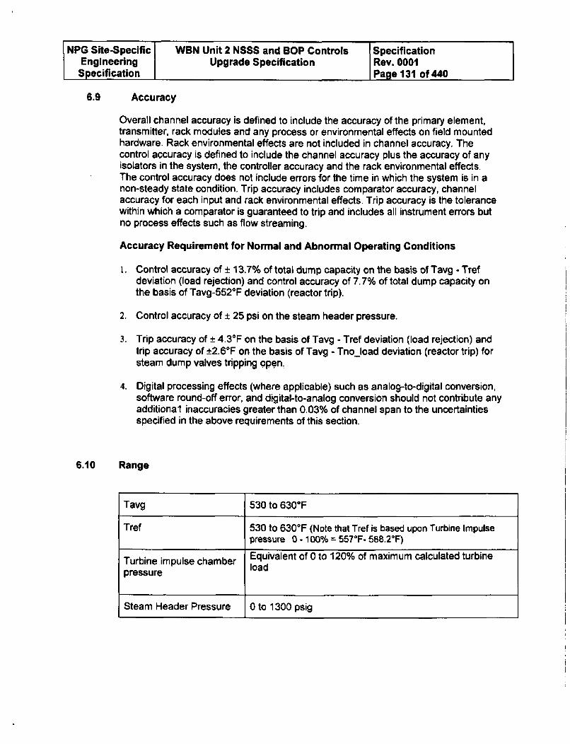
SNPG Site-Specific WBN Unit 2 NSSS and SOP Controls SpecificationEngineering Upgrade Specification Rev. 0001
Specification Page 131 of 440
6.9 Accuracy
Overall channel accuracy is defined to include the accuracy of the primary element,transmitter, rack modules and any process or environmental effects on field mountedhardware. Rack environmental effects are not included in channel accuracy. Thecontrol accuracy is defined to include the channel accuracy plus the accuracy of anyisolators in the system, the controller accuracy and the rack environmental effects.The control accuracy does not include errors for the time in which the system is in anon-steady state condition. Trip accuracy includes comparator accuracy, channelaccuracy for each input and rack environmental effects. Trip accuracy is the tolerancewithin which a comparator is guaranteed to trip and includes all instrument errors butno process effects such as flow streaming.
Accuracy Requirement for Normal and Abnormal Operating Conditions
i. Control accuracy of ± 13.7% of total dump capacity on the basis of Tavg - Trefdeviation (load rejection) and control accuracy of 7.7% of total dump capacity onthe basis of Tavg-552°F deviation (reactor trip).
2. Control accuracy of ± 25 psi on the steam header pressure.
3. Trip accuracy of ± 4.30 F on the basis of Tavg - Tref deviation (load rejection) andtrip accuracy of ±2.60F on the basis of Tavg - Tno load deviation (reactor trip) forsteam dump valves tripping open,
4. Digital processing effects (where applicable) such as analog-to-digital conversion,software round-off error, and digital-to-analog conversion should not contribute anyadditional inaccuracies greater than 0.03% of channel span to the uncertaintiesspecified in the above requirements of this section.
6.10 Range
Tavg 530 to 630°F
Tref 530 to 630°F (Note that Tref is based upon Turbine Impulsepressure 0 - 100% = 5570F- 588.2°F)
Turbine impulse chamber Equivalent of 0 to 120% of maximum calculated turbine
pressure load
Steam Header Pressure 0 to 1300 psig
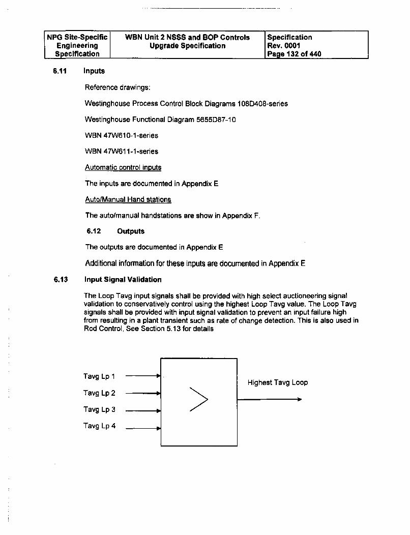
NPG Site-Specific WBN Unit 2 NSSS and BOP Controls SpecificationEngineering Upgrade Specification Rev. 0001Specification Page 132 of 440
6.11 Inputs
Reference drawings:
Westinghouse Process Control Block Diagrams 108D408-series
Westinghouse Functional Diagram 5655D87-10
WBN 47W61 0-1 -series
WBN 47W61 1-1 -series
Automatic control inputs
The inputs are documented in Appendix E
Auto/Manual Hand stations
The auto/manual handstations are show in Appendix F.
6.12 Outputs
The outputs are documented in Appendix E
Additional information for these inputs are documented in Appendix E
6.13 Input Signal Validation
The Loop Tavg input signals shall be provided with high select auctioneering signalvalidation to conservatively control using the highest Loop Tavg value. The Loop Tavgsignals shall be provided with input signal validation to prevent an input failure highfrom resulting in a plant transient such as rate of change detection. This is also used inRod Control, See Section 5.13 for details
Tavg Lp 1
Tavg Lp 2
Tavg Lp 3
Tavg Lp 4
Highest Tavg Loop
-4
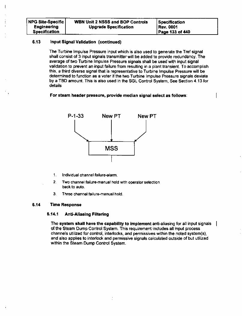
NPG Site-Specific WBN Unit 2 NSSS and BOP Controls SpecificationEngineering Upgrade Specification Rev. 0001Specification Page 133 of 440
6.13 Input Signal Validation (continued)
The Turbine Impulse Pressure input which is also used to generate the Tref signalshall consist of 3 input signals transmitter will be added to provide redundancy. Theaverage of two Turbine Impulse Pressure signals shall be used with input signalvalidation to prevent an input failure from resulting in a plant transient. To accomplishthis, a third diverse signal that is representative to Turbine Impulse Pressure will bedetermined to function as a voter if the two Turbine Impulse Pressure signals deviateby a TBD amount. This is also used in the SGL Control System, See Section 4.13 fordetails
For steam header pressure, provide median signal select as follows:
P-1-33 New PT
IFNew PT
I MSS I
1, Individual channel failure-alarm.
2. Two channel failure-manual hold with operator selectionback to auto.
3. Three channel failure-manual hold.
6.14 Time Response
6.14.1 Anti-Aliasing Filtering
The system shall have the capability to implement anti-aliasing for all input signalsof the Steam Dump Control System. This requirement includes all input processchannels utilized for control, interlocks, and permissives within the noted system(s),and also applies to interlock and permissive signals calculated outside of but utilizedwithin the Steam Dump Control System.
I
NPG Site-Specific WBN Unit 2 NSSS and BOP Controls SpecificationEngineering Upgrade Specification Rev. 0001Specification Page 134 of 440
6.14.2 Control Processors Response Time
The control processor response time (from the control system's input module/s tooutput module/s including control system processing time) for all input signals of theSteam Dump Control System shall not exceed 250 milli-seconds. This requirementincludes all input process channels utilized for control, interlocks, and permissiveswithin the noted system(s), and also applies to interlock and permissive signalscalculated outside of but utilized within Steam Dump Control System. Thisrequirement includes all modulating control signals, bistable logic (on/off) controlsignals, mode signals, and signals to the main control board (indication, status, andalarm/annunciators).
6.14.3 Communication Response Time between ControlProcessors
Communication between different Control Processor pairs shall not exceed 500 milli-seconds for signals involved in closed loop control for this function.
6.14.4 Manual Control Response
The total delay for all manual component control signals of Steam Dump ControlSystem shall be no greater than 1 second.
6.15 Controller Reset Windup and Recovery Characteristics
The control system shall not be susceptible hardware or software controller resetwindup. After the out-of-range signal causing the overload returns from the overloadcondition, all component units of the system must recover from the saturated conditionand return to their correct output values (within normal error limits) within 1 second.During recovery from overload, the output of all affected component units mustprogress smoothly from the saturated value to the correct value without oscillation orovershoot larger than 1% (peak to peak) of channel range exclusive of the theoreticalamplification of lead/lag and rate/lag units. The I second recovery time specifiedabove need be met only when all externally adjustable time delays are set to 0.0. Therequirements on oscillation and overshoot should be met even with all externallyadjustable time delays set to 0.0.
6.16 Noise Levels
The root mean square noise should be limited to 1.2% of output span in all channels.The noise limitation does not apply to process signal noise, e.g., fluctuations inapplicable process variables, but should apply to all noise generated from detectingthe signal onward. Where applicable, the requirement should be met with all lead, lag,and filter time constants set to 0.0 and module gains set to 1.
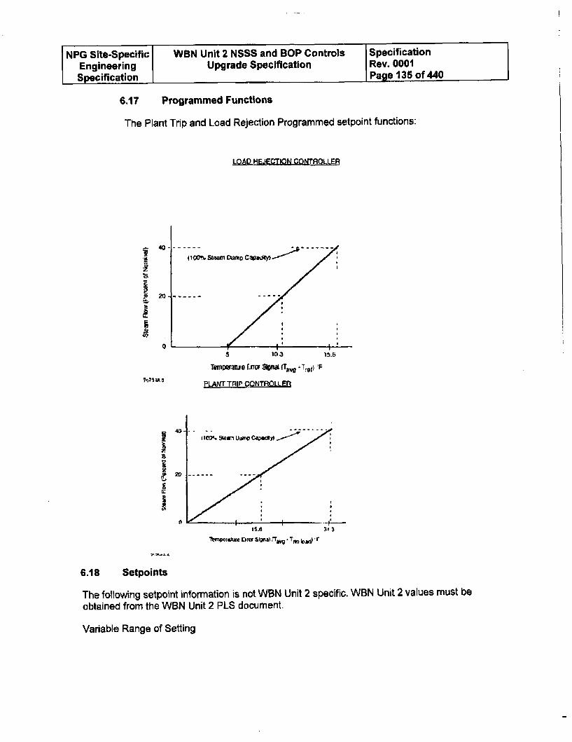
NPG Site-Specific WBN Unit 2 NSSS and BOP Controls SpecificationEngineering Upgrade Specification Rev. 0001Specification Page 135 of 440
6.17 Programmed Functions
The Plant Trip and Load Rejection Programmed setpoint functions:
LOAD HEJECTION COnRQLOLLER
l0O% Stem Dump CadtI-I~ -
€,0 ---------
0 -L-L5 103 15.6
Twu•lmue Lna Spahi (Tim T.*i 'F
PLANT TRIP CONTROLLER
Ir
iUiC
I
IIWSterUw1vC4D.a$..r~" ,~;2
Ib
J
ThmporUt r•lra S&ip&lh ,'w T l adx '.r
6.18 Setpoints
The following setpoint information is not WBN Unit 2 specific. WBN Unit 2 values must beobtained from the WBN Unit 2 PLS document.
Variable Range of Setting
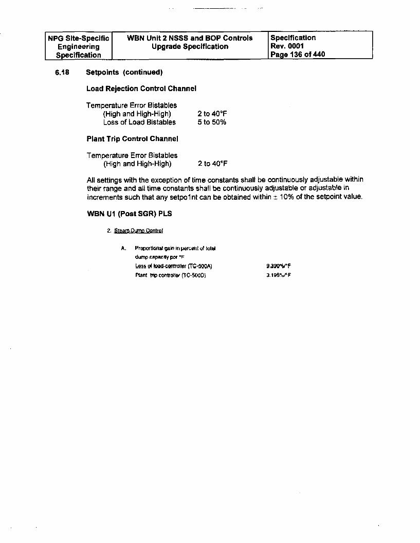
NPG Site-Specific WBN Unit 2 NSSS and BOP Controls SpecificationEngineering Upgrade Specification Rev. 0001Specification Page 136 of 440
6.18 Setpoints (continued)
Load Rejection Control Channel
Temperature Error Bistables(High and High-High) 2 to 40°FLoss of Load Bistables 5 to 50%
Plant Trip Control Channel
Temperature Error Bistables(High and High-High) 2 to 400 F
All settings with the exception of time constants shall be continuously adjustable withintheir range and all time constants shall be continuously adjustable or adjustable inincrements such that any setpolnt can be obtained within ± 10% of the setpoint value.
WBN UI (Post SGR) PLS
2. Steam Dumn Control
A. Proportional gain in periett uf total
dump capacity por 0F
Loss of.Ioad-cotg.allpr (T'.•-OA) ,3;MIF
Plant trp controller (TC-5.OD) 3.aIOS°,,PF
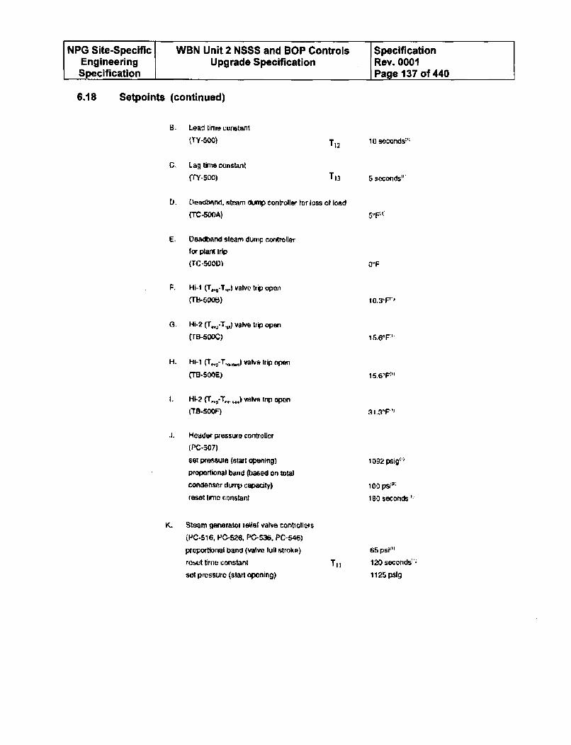
NPG Site-Specific WBN Unit 2 NSSS and SOP Controls SpecificationEngineering Upgrade Specification Rev. 0001Specification Page 137 of 440
6.18 Setpoints (continued)
B_ Lead tirns ccritant
(TY-500)
C, Lag tirne constant
frY-see)
T1 2 11 9seconds:P
T13 5 3seconds"r
D. Lleadwnd, steam dump controller tor loss of load
(TC-500A)
E- Deadband steam durrmp cotroller
for plant trip
(TO -500D)
F. Hi-I (T_.,-T,) valve trip open
fTB-500B)
G. Hi-2 (r•;-T.,) valve trip open
(TB-0oC)
H. W-1 -T..i) valv, trip open
(T.-SOCE)
1. HI-2 (- .J- v,,) alve trip open
(rB5SO5F)
.j. Header pressure controller
(PC-507)
sex pressure (start opening)proportional band (based on total
condenser dump capacity)
reset lime constant
K. Steam generateo iele valve contiollers
(PC-516, PC-526, PC-536. PC-546)
proportioral band (valve lull Arokpk)
reset time constant
sOl pressure (start oponing)
15.6'F"'
11. 3T ')
1092 psigl'>
100 psi-:
180 seconds':'
65 psi"'
TI, 120 seorids"'
1125 pslg
NPG Site-Specific WBN Unit 2 NSSS and BOP Controls SpecificationEngineering Upgrade Specification Rev. 0001Specification Page 138 of 440
6.19 Requirements for Test and Calibration
With the exception of the Low-Low Tavg interlock, the steam dump control system isnot a protection system, and thus, does not require the capability of being tested atpower. The Tavg interlock is part of the protection system and must be capable ofbeing tested at power.
6.20 Requirements for Associated Equipment
Steam Dump Valves
All steam dump valves should fall closed in the event of a loss of control systempower.
Condenser Steam Dump Requirements and Arrangement
The steam dump system uses modulating air-operated valves which fail closed in theevent of loss of electrical power or air supply.
Condenser Steam Dump Valve Design Requirements
All 12 steam dump valves are capable of:
1. Flow per valve at a valve inlet pressure of 900 psig and a valve outlet pressureof 250 psig - 532,170 lb/hr.
2. Maximum flow per valve at a valve inlet pressure of 1185 psig and a valveoutlet pressure of 250 psig - 970,000 lb/hr.
3. Valve Trip Open Time - Going from full closed to full open, within 3 secondsafter receiving a trip open signal, over the steam pressure range from 1185psig to 785 psig.
4. Valve Trip Close Time - Going from full open to full closed, within 5 secondsafter receiving a trip closed signal, over the steam pressure range from 100psia to the main steam system design pressure.
5. Valve Stroke Time - Being modulated, with a maximum full stroke time of 20seconds, over the steam pressure range from 100 psia to the main steamsystem design pressure.
6. Valve Backpressure - For steam dump flow varying between zero and full flow,valve backpressure will vary between 2 in. Hga and 250 psig.
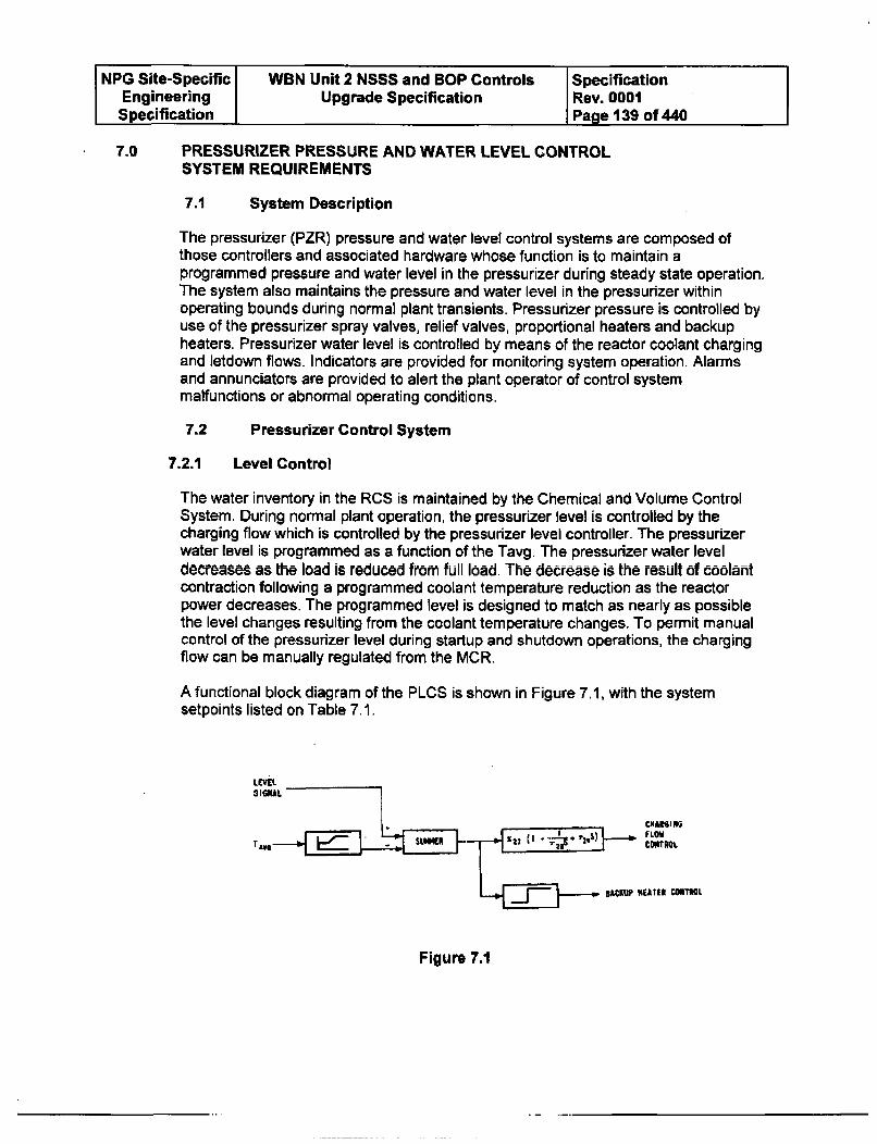
NPG Site-Specific WBN Unit 2 NSSS and BOP Controls SpecificationEngineering Upgrade Specification Rev. 0001Specification Page 139 of 440
7.0 PRESSURIZER PRESSURE AND WATER LEVEL CONTROLSYSTEM REQUIREMENTS
7.1 System Description
The pressurizer (PZR) pressure and water level control systems are composed ofthose controllers and associated hardware whose function is to maintain aprogrammed pressure and water level in the pressurizer during steady state operation.The system also maintains the pressure and water level in the pressurizer withinoperating bounds during normal plant transients. Pressurizer pressure is controlled byuse of the pressurizer spray valves, relief valves, proportional heaters and backupheaters. Pressurizer water level is controlled by means of the reactor coolant chargingand letdown flows. Indicators are provided for monitoring system operation. Alarmsand annunciators are provided to alert the plant operator of control systemmalfunctions or abnormal operating conditions.
7.2 Pressurizer Control System
7.2.1 Level Control
The water inventory in the RCS is maintained by the Chemical and Volume ControlSystem. During normal plant operation, the pressurizer level is controlled by thecharging flow which is controlled by the pressurizer level controller. The pressurizerwater level is programmed as a function of the Tavg. The pressurizer water leveldecreases as the load is reduced from full load. The decrease is the result of coolantcontraction following a programmed coolant temperature reduction as the reactorpower decreases. The programmed level is designed to match as nearly as possiblethe level changes resulting from the coolant temperature changes. To permit manualcontrol of the pressurizer level during startup and shutdown operations, the chargingflow can be manually regulated from the MCR.
A functional block diagram of the PLCS is shown in Figure 7.1, with the systemsetpoints listed on Table 7.1.
* IGNAB
CHARGINGTvS 7: . 13 ) FLOW
u ,CONTROL
BACKUP NEATR CONTROL
Figure 7.1
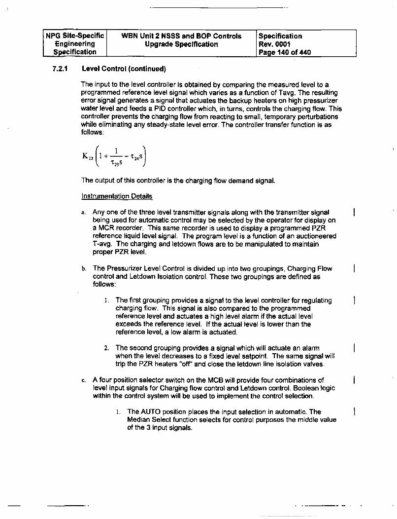
NPG Site-Specific WBN Unit 2 NSSS and BOP Controls SpecificationEngineering Upgrade Specification Rev. 0001Specification Page 140 of 440
7.2.1 Level Control (continued)
The input to the level controller is obtained by comparing the measured level to aprogrammed reference level signal which varies as a function of Tavg. The resultingerror signal generates a signal that actuates the backup heaters on high pressurizerwater level and feeds a PID controller which, in turns, controls the charging flow. Thiscontroller prevents the charging flow from reacting to small, temporary perturbationswhile eliminating any steady-state level error. The controller transfer function is asfollows:
K 22 I+ 1 +T4ST23S
The output of this controller is the charging flow demand signal.
Instrumentation Details
a. Any one of the three level transmitter signals along with the transmitter signalbeing used for automatic control may be selected by the operator for display ona MCR recorder. This same recorder is used to display a programmed PZRreference liquid level signal. The program level is a function of an auctioneeredT-avg. The charging and letdown flows are to be manipulated to maintainproper PZR level.
b. The Pressurizer Level Control is divided up into two groupings, Charging Flowcontrol and Letdown Isolation control. These two groupings are defined asfollows:
I. The first grouping provides a signal to the level controller for regulatingcharging flow. This signal is also compared to the programmedreference level and actuates a high level alarm if the actual levelexceeds the reference level. If the actual level is lower than thereference level, a low alarm is actuated.
2. The second grouping provides a signal which will actuate an alarmwhen the level decreases to a fixed level setpoint. The same signal willtrip the PZR heaters "off' and close the letdown line isolation valves.
c. A four position selector switch on the MCB will provide four combinations oflevel input signals for Charging flow control and Letdown control. Boolean logicwithin the control system will be used to implement the control selection.
1. The AUTO position places the input selection in automatic. TheMedian Select function selects for control purposes the middle valueof the 3 input signals.
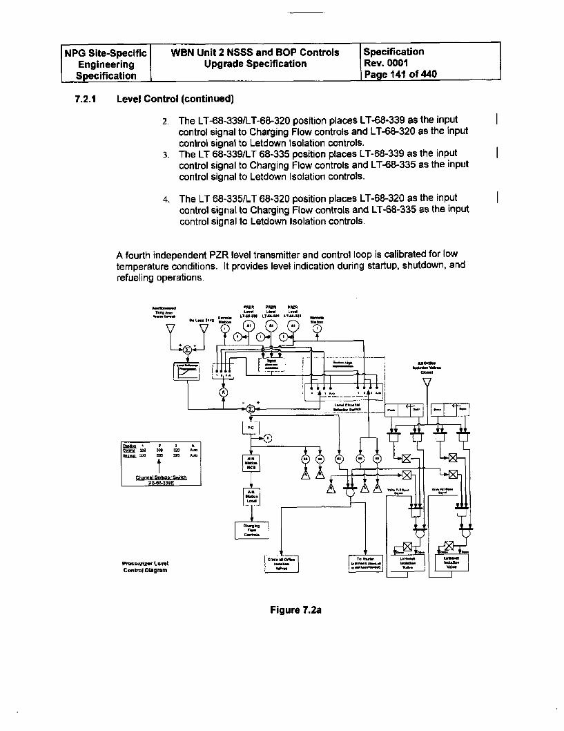
NPG Site-Specific WBN Unit 2 NSSS and BOP Controls SpecificationEngineering Upgrade Specification Rev. 0001Specification Page 141 of 440
7.2.1 Level Control (continued)
2. The LT-68-339/LT-68-320 position places LT-68-339 as the inputcontrol signal to Charging Flow controls and LT-68-320 as the inputcontrol signal to Letdown Isolation controls.
3. The LT 68-339/LT 68-335 position places LT-68-339 as the inputcontrol signal to Charging Flow controls and LT-68-335 as the inputcontrol signal to Letdown Isolation controls.
4. The LT 68-3351LT 68-320 position places LT-68-320 as the inputcontrol signal to Charging Flow controls and LT-68-335 as the inputcontrol signal to Letdown Isolation controls.
A fourth independent PZR level transmitter and control loop is calibrated for lowtemperature conditions. It provides level indication during startup, shutdown, andrefueling operations.
A PRIM ParU PpiMz,LIA-4 1.94-L3 L?44J.U
-- S
..... ....
~j 1 2 2 AGonai 133 339 320 AMlonkrm l 320 33 5 A'..¶ MCI
?*46339E
Vbt.
Conitral Diagram
Figure 7.2a
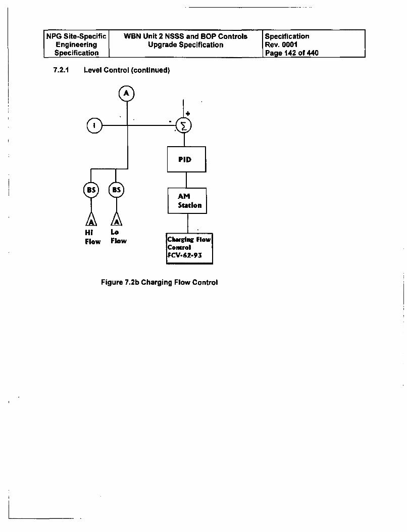
INPG Site-Specific WBN Unit 2 NSSS and BOP Controls SpecificationEngineering Upgrade Specification Rev. 0001Specification Page 142 of 440
7.2.1 Level Control (continued)
Figure 7.2b Charging Flow Control
NPG Site-Specific WBN Unit 2 NSSS and BOP Controls SpecificationEngineering Upgrade Specification Rev. 0001Specification Page 143 of 440
7.2.1 Level Control (continued)
The following setpoint information is not WBN Unit 2 specific. WBN Unit 2 valuesmust be obtained from the WBN Unit 2 PLS document.
Pressurizor Level Control
A. Level program as funclion of T,1 (TC-4128)
1 For full load T., = 588.2
(high limit)
2. For full load T., - 586.2
(high limil)
3. For T., = -557F
(low limit)
62% of level
span"; (')
59.6% of level
span'41 (*)
25% of level
span'4r (V)(Program is linear frawm 5571F to full load T0 .)
The actual level cart be +6.6% of level span at 62% level. A positive
uncertainty is not necessary for safety analysis and, therefore, a negative
pomcont of level span is not provided.
B. Low-Low level heater cutout
(letdown Ono isolation)
(LB-4590 and LB-460D) 17 percent of
level spin
The PD Charging pump has been disabled so item C is nolonger valid and has been deleted.
D. Row controller (FC-121)
I. Proportional gain
2. Reset time constant
3. Low Limit (HY-121)
1 % value demand?
% charging flow
30 seconds
55 gaVmmn
Table 7.1
NPG Site-Specific WBN Unit 2 NSSS and BOP Controls SpecificationEngineering Upgrade Specification Rev. 0001Specification Page 144 of 440
7.2.2 Pressure Control
During normal operation, RCS pressure is maintained by the pressurizer heatercontroller at or near 2235 psig, while the steady state PZR liquid level is controlledby the CVCS charging flow. When the reactor power level is less than 15 percent,the reactor is controlled manually. At power above 15 percent, the RCS controlswill automatically maintain, by control rod movement, an average coolanttemperature at a value which is a function of the power/load relationships. RCStemperature can also be controlled by manually moving the control rods oradjusting the chemical shim. One hundred percent power Tavg is 586.20F (WBNUnit I value). In hot standby, two RCS loops provide sufficient heat removalcapability for removing core decay heat even in the event of a rod bank withdrawalaccident; however, a single RCS loop provides sufficient heat removal if a bankwithdrawal accident cannot be prevented, i. e., by opening the Reactor Tripbreakers.
Design Basis of the Pressurizer Pressure Control System
The Pressurizer Pressure Control System (PPCS) maintains pressure at the set valueby 4 means:
1. Spray Valves2. Relief Valves3. Proportional Heaters4. Back-up Heaters
Together, the heaters, spray valves and relief valves maintain the pressure at thesetpoint value and present reactor trip as a result of pressure variations caused bydesign transients.
Description of the Pressurizer Pressure Control System
Figure 7.3 is a functional block diagram of the PPCS. The PPCS setpoints are listed inTable 7.2. The pressurizer pressure signal feeds a PID controller of the following type:
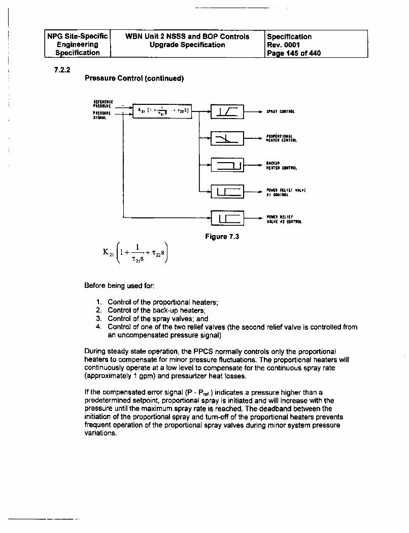
NPG Site-Specific WBN Unit 2 NSSS and BOP Controls SpecificationEngineering Upgrade Specification Rev. 0001Specification Page 145 of 440
7.2.2Pressure Control (continued)
IUUENCCPIESSU•E -
K21
SPRA1 CONTROL
PuO~h? MCALMEATE t CONTROL
HEATER COlTIOL
POWER RELIEF VALVEIII CONTIOL
PMWL[ E LIEFVALV[ 1 2 COINTROL
Figure 7.3
1+ + T22s
"12 1s
Before being used for:
1. Control of the proportional heaters;2. Control of the back-up heaters;3. Control of the spray valves; and4. Control of one of the two relief valves (the second relief valve is controlled from
an uncompensated pressure signal)
During steady state operation, the PPCS normally controls only the proportionalheaters to compensate for minor pressure fluctuations. The proportional heaters willcontinuously operate at a low level to compensate for the continuous spray rate(approximately 1 gpm) and pressurizer heat losses.
If the compensated error signal (P - Pr) indicates a pressure higher than apredetermined setpoint, proportional spray is initiated and will increase with thepressure until the maximum spray rate is reached. The deadband between theinitiation of the proportional spray and turn-off of the proportional heaters preventsfrequent operation of the proportional spray valves during minor system pressurevariations.
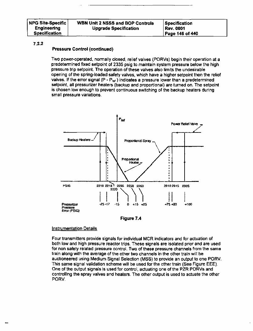
NPG Site-Specific WBN Unit 2 NSSS and BOP Controls SpecificationEngineering Upgrade Specification Rev. 0001Specification Page 146 of 440
7.2.2Pressure Control (continued)
Two power-operated, normally closed, relief valves (PORVs) begin their operation at apredetermined fixed setpoint of 2335 psig to maintain system pressure below the highpressure trip setpoint. The operation of these valves also limits the undesirableopening of the spring-loaded safety valves, which have a higher setpoint then the reliefvalves. If the error signal (P - P~r ) indicates a pressure lower than a predeterminedsetpoint, all pressurizer heaters (backup and proportional) are turned on. The setpointis chosen low enough to prevent continuous switching of the backup heaters duringsmall pressure variations.
PressurlzerPrm•ueError (PSIG)
Figure 7.4
Instrumentation Details
Four transmitters provide signals for individual MCR indicators and for actuation ofboth low and high pressure reactor trips. These signals are isolated prior and are usedfor non safety related pressure control. Two of these pressure channels from the sametrain along with the average of the other two channels in the other train will beauctioneered using Medium Signal Selection (MSS) to provide an output to one PORV.This same signal validation scheme will be used for the other train (See Figure EEE).One of the output signals is used for control, actuating one of the PZR PORVs andcontrolling the spray valves and heaters. The other output is used to actuate the otherPORV.
SNPG Site-Specific WON Unit 2 NSSS and BOP Controls SpecificationEngineering Upgrade Specification IRev. 0001Specification Page 147 of 440
7.2.2Pressure Control (continued)
The inputs should be chosen so that it is not possible for failure of a same pressurechannel to could cause actuation of both PORVs or to actuate and interlock the samevalve. This same requirement is applicable for the redundant control processor pairs,each PORV control will be implemented in separate redundant control processor pairs.The PZR pressure control system will maintain or restore the PZR pressure to thedesign pressure following normal operational transients. Pressure is controlled by athree mode controller whose output is a function of pressure error and time duration ofthe error. The lower portion of the controller's output range operates the PZR heaters.For normal operation, a small group of heaters is controlled by variable power tomaintain the PZR operating pressure. If the controller output signal falls toward thebottom of the variable heater control range all the heaters are turned on.
The upper portion of the controller's output range operates the PZR spray valves andone PORV. The spray valves are proportionally controlled in a range above the upperend of the variable heaters with spray flow increasing as the controller signal rises. Ifthe controller signal rises significantly above the proportional range of the sprayvalves, a PORV (interlocked with a separate transmitter to prevent spurious operation)is opened. A further increase in pressure will actuate a high pressure reactor trip. Aseparate transmitter (interlocked also with a separate transmitter so as to preventspurious operation) provides PORV operation for a second valve upon high PZRpressure. A signal interlock is required to open (or keep open) the PORV. The fourPZR pressure transmitters are connected to three PZR vessel nozzles with channels(PT-68-322 and-323) sharing a sense line. This sharing of a sense line is acceptablesince a failure of the sense line would cause the initiation of a reactor trip signal due tolow pressure exhibited at the two transmitters. This reactor trip signal initiation causesthe reactor unit to achieve its safe state, thus the protective function remains operableand Ref. 7.5.9 is met.
a. Any one of the four pressure transmitter signals along with the transmittersignal being used for automatic control may be selected by the operator fordisplay on a MCR recorder.
b. The Pressurizer Pressure Control is divided up into two groupings, NormalPressure control and Abnormal High control. The groupings are divided on atrained channel basis. If Train A (Protection I or Ill) inputs are used for normalpressure control then Train B (Protection II or IV) inputs are used for AbnormalHigh control. These two groupings are defined as follows:
1. The first grouping provides output signals used for control, actuatingone of the PZR PORVs and controlling the spray valves and heaters.Normal pressure control is performed by modulating and turning onheater when pressure goes below defined pressure setpoints andmodulating open the spray valves when pressure increases abovedefined setpoints.
NPG Site-Specific WBN Unit 2 NSSS and BOP Controls SpecificationEngineering Upgrade Specification Rev. 0001Specification Page 148 of 440
7.2.2Pressure Control (continued)
2. The other output is used to actuate the other PORV. The inputs to thechannel selector switch should be chosen so that it is not possible forthe same pressure channel to be used to actuate both PORVs or forone pressure channel to actuate and interlock the same valve.
c. A four position selector switch (XS-68-340D) on the MCB will provide fourcombinations of level input signals for pressure control. Boolean logic within thecontrol system will be used to implement the control selection. The switchingfunction will be divided up into two separate processor groups so that a singlefailure of a processor group will not prevent functioning of any pressure controlfunction when demanded or result in the spurious operation of a controlleddevice such as a PORV.
i. The AUTO position places the input selection in automatic. When inAUTO, PT-68-323 or PT-68-340 will be selected as input to theNormal pressure control functions (Heaters, and Spray valves) andalso provide control of PORV PCV-68-334 along with an interlockfor the other PORV PCV-68-340A. The other two transmitters, PT-68-322 or PT-68-334, will be selected as input and provide controlof PORV PCV-68-340A along with an interlock for the other PORVPCV-68-334. Each pair of transmitters will be compared to theaverage of the other pair using a Median Select function. See thePressurizer Pressure Signal Validation Scheme (Figure 7.12).
2. The PT 68-340/PT 68-322 position places PT-68-340 as the inputcontrol signal to Normal pressure controls and PT-68-322 as theinput control signal to PORV control.
3. The PT 68-340/PT 68-334 position places PT-68-340 as the inputcontrol signal to Normal pressure controls and PT-68-334 as theinput control signal to PORV control.
4. The PT 68-323/PT 68-334 position places PT-68-323 as the inputcontrol signal to Normal pressure controls and PT-68-334 as theinput control signal to PORV control.
d. One pressure channel selector switch is provided in the MCR to select two ofthe four isolated outputs of these pressure channels.
The PZR pressure control system will maintain or restore the PZR pressure to thedesign pressure following normal operational transients. Pressure is controlled bya three mode controller whose output is a function of pressure error and timeduration of the error. The lower portion of the controller's output range operatesthe PZR heaters. For normal operation, a small group of heaters is controlled byvariable power to maintain the PZR operating pressure. If the controller outputsignal falls toward the bottom of the variable heater control range all the heatersare turned on.
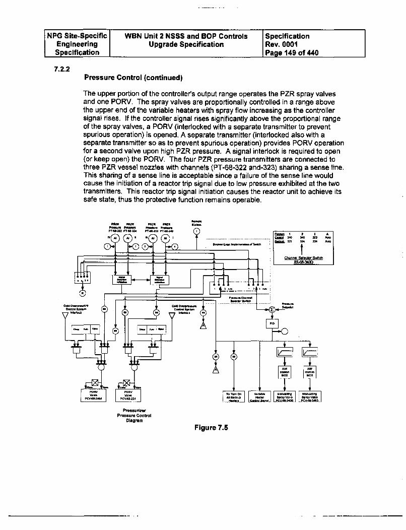
NPG Site-Specific WBN Unit 2 NSSS and BOP Controls SpecificationEngineering Upgrade Specification Rev. 0001Specification Page 149 of 440
7.2.2Pressure Control (continued)
The upper portion of the controllers output range operates the PZR spray valvesand one PORV. The spray valves are proportionally controlled in a range abovethe upper end of the variable heaters with spray flow increasing as the controllersignal rises. If the controller signal rises significantly above the proportional rangeof the spray valves, a PORV (interlocked with a separate transmitter to preventspurious operation) is opened, A separate transmitter (interlocked also with aseparate transmitter so as to prevent spurious operation) provides PORV operationfor a second valve upon high PZR pressure. A signal interlock is required to open(or keep open) the PORV. The four PZR pressure transmitters are connected tothree PZR vessel nozzles with channels (PT-68-322 and-323) sharing a sense line.This sharing of a sense line is acceptable since a failure of the sense line wouldcause the initiation of a reactor trip signal due to low pressure exhibited at the twotransmitters. This reactor trip signal initiation causes the reactor unit to achieve itssafe state, thus the protective function remains operable.
f..a-W.6t
Ctfl 34L 3 i AkM8,0 Mn &M MA Aft
Boom Loo nes~o d St
~I~b - 1 Channl Sedm swfthd
PressurizerPressure Conftrol
Diagram
Figure 7.5
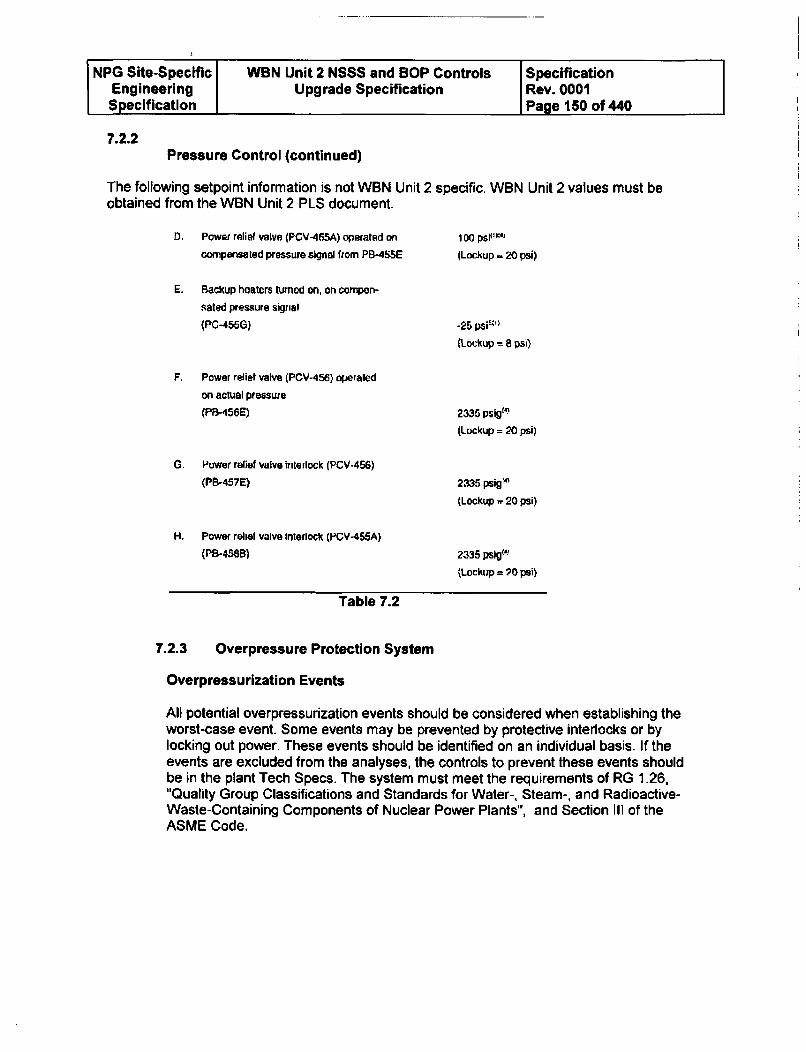
NPG Site-Specific WBN Unit 2 NSSS and BOP Controls SpecificationEngineering Upgrade Specification Rev. 0001Specification Page 150 of 440
7.2.2Pressure Control (continued)
The following setpoint information is not WBN Unit 2 specific. WBN Unit 2 values must beobtained from the WBN Unit 2 PLS document.
D. Power relief valve (PCV-455A) operated on
compensated pressure signal from PB-4SSE
E. Backup heaters turned on, on cornpon-
sated pressure signal
(PC-455G)
F. Power relief valve (PCV-456) operaled
on actual pressure
(PB-456E)
G. Power refief valve interlock (PCV-456)
(PB-457E)
H. Power relief valve interlock (PCV-455A)
(PS-45,B)
100 pso• "•
(Lockup a 20 psi)
-25 pSiE')
(Lockup = 8 psi)
2335 psig14 )
(Lockup = 20 psi)
2335 psigZ
(Lockup -. 20 psi)
2335 psig"'a
(Lockup = 70 psi)
Table 7.2
7.2.3 Overpressure Protection System
Overpressurization Events
All potential overpressurization events should be considered when establishing theworst-case event. Some events may be prevented by protective interlocks or bylocking out power. These events should be identified on an individual basis. If theevents are excluded from the analyses, the controls to prevent these events shouldbe in the plant Tech Specs. The system must meet the requirements of RG 1.26,"Quality Group Classifications and Standards for Water-, Steam-, and Radioactive-Waste-Containing Components of Nuclear Power Plants", and Section II of theASME Code.
NPG Site-Specific WBN Unit 2 NSSS and BOP Controls SpecificationEngineering Upgrade Specification Rev. 0001Specification Page 151 of 440
7.2.3 Overpressure Protection System (continued)
Design Basis of the COMS
Plant Startup and Shutdown
The Cold Overpressurization Mitigation System (COMS) shall be designed andinstalled which will prevent exceeding the applicable Tech Spec and 10CFR50Appendix G limits for the RCS while operating at low temperatures. The system shallbe capable of relieving pressure during all anticipated overpressurization events at arate sufficient to satisfy the Tech Spec limits, particularly while the RCS is water-solid.The system shall have the ability to be manually armed by the operator. The armingsetpoint shall be defined in the Tech Spec, and the instruments for overprotectionshall be under periodic surveillance.
Description of the COMS
Plant startup encompasses operations which bring the reactor plant from coldshutdown to no-load power operating temperature and pressure. To initiate heat-up,the PZR heaters are energized to begin forming a steam bubble in the PZR. PZRheatup continues until approximately 430*F resulting in an RCS pressure ofapproximately 330 psig. The PZR level control is then placed in Auto and the RCPsare started. Nil ductility temperature limitations of the reactor vessel, impose an upperlimit of approximately 450 psig. The RCPs are started one at a time allowingapproximately five minutes between each pump startup. RHR system cooling isisolated and the RCS temperature increases to 180 0F. After ensuring that SGblowdown is in service, that one CCP is operable, and that the CRDM cooling fans areon, RCS temperature is taken to 350'F. At this point, letdown flow is maintained atless than or equal to 120 gpm. When the temperature of each cold leg is greater than3500F, the COMS is blocked. The system is then taken to hot standby conditions of5570F and 2235 psig. As RCS temperature increases, the PZR heaters are manuallycontrolled to maintain adequate suction pressure for the RCPs. When the normaloperating pressure of 2235 psig Is reached, PZR heater and spray controls aretransferred from manual to automatic control, The SI initiation signal is automaticallyunblocked at 1970 psig.
Instrumentation Details
The PORVs receive pressure control signals from instrumentation loops connected tothe pressurizer. Wide range-temperature signals from the hot legs and cold legs ofloops 1 and 2 are provided for PCV-68-340A. Wide range temperature indication fromthe hot legs and cold legs of loops 3 and 4 are provided for PCV-68-334. Wide rangepressure and temperature signals operate the valves from the COMs instrumentation(See section 3.3.2.3). These valves have position indication in the MCR. In addition,an acoustic monitoring system is provided to indicate when a valve is not fully closed.An alarm in the MCR indicates when either valve is not fully closed. See Table 2 foralve power supply.
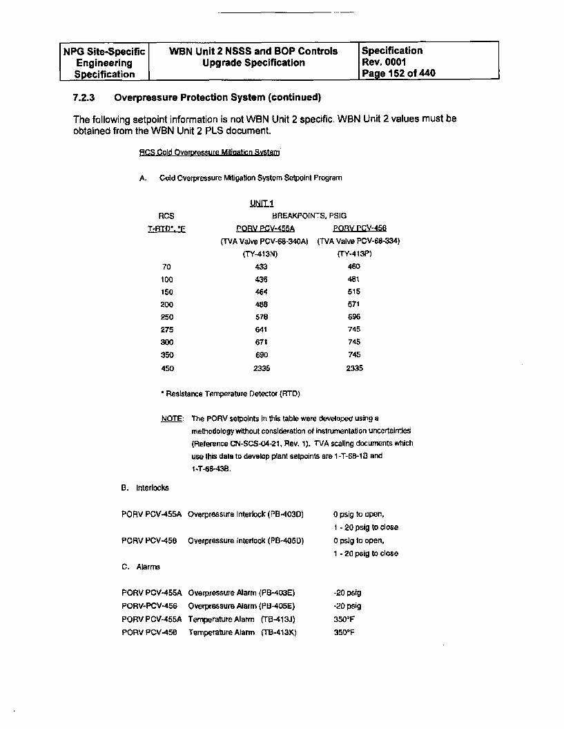
NPG Site-Specific WBN Unit 2 NSSS and BOP Controls SpecificationEngineering Upgrade Specification Rev. 0001Specification Page 152 of 440
7.2.3 Overpressure Protection System (continued)
The following setpoint information is not WBN Unit 2 specific. WBN Unit 2 values must beobtained from the WBN Unit 2 PLS document.
RCS Cold Overoressure Mitigation System
A. Cold Overpressure Mitigation System Setpoint Program
1UNIT!1RCS
70
I00
150
200
250
275
30O
350
450
rREAKPO1NTS, PSIG
,PORV POV-455A PonV PCV-456
(TVA Valve PCV-68-340A) (TVA Valve PCV-68-334)
(TY-413N) (TY-413P)
433
436
464
488
578
641
671
690
2335
460
481
515
571
696
745
745
745
2335
' Resistance Temperature Detector (RTD)
NOTE: The PORV setpoints In this table were developed using a
methodology without consideration of instrumentation uncertainties
(Reference CN-SCS-04-21, Rev. 1). TVA scaling documents which
use this data to develop plant selpoinls are I -T-6B-1 B andI -T-68-438.
B. Interlocks
PORV PCV-455A Overpressure Interlock (PB-403D)
PORV PCV-456 Overpressure Interlock (PB-405D)
0 psig to open,1 - 20 psig to close
0 psig to open,1 - 20 psig to close
C. Alarms
PORV PCV-455A
PORV-PCV-456
PORV PCV-455A
PORV PCV-456
Overpressure Alarm (PB-403E)
Overpressure Alarm (PB-405E)
Temperature Alarm (TB-413J)
Temperature Alarm (TB.413K)
-20 psig
-20 psig
3503 F
3500 F
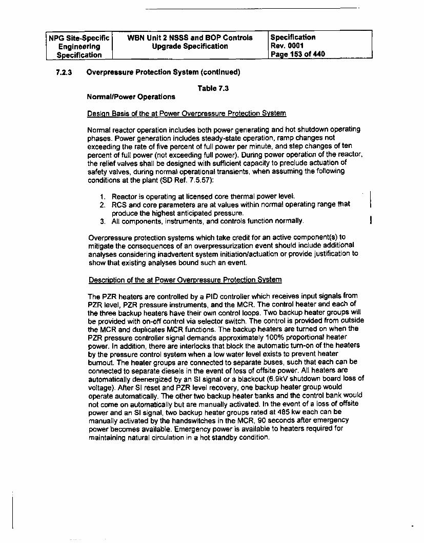
NPG Site-Specific WBN Unit 2 NSSS and BOP Controls SpecificationEngineering Upgrade Specification Rev. 0001Specification Page 153 of 440
7.2.3 Overpressure Protection System (continued)
Table 7.3NormallPower Operations
Design Basis of the at Power Overpressure Protection System
Normal reactor operation includes both power generating and hot shutdown operatingphases. Power generation includes steady-state operation, ramp changes notexceeding the rate of five percent of full power per minute, and step changes of tenpercent of full power (not exceeding full power). During power operation of the reactor,the relief valves shall be designed with sufficient capacity to preclude actuation ofsafety valves, during normal operational transients, when assuming the followingconditions at the plant (SD Ref. 7.5.57):
1. Reactor is operating at licensed core thermal power level.2. RCS and core parameters are at values within normal operating range that
produce the highest anticipated pressure.3. All components, instruments, and controls function normally.
Overpressure protection systems which take credit for an active component(s) tomitigate the consequences of an overpressurization event should include additionalanalyses considering inadvertent system initiation/actuation or provide justification toshow that existing analyses bound such an event.
Description of the at Power Overpressure Protection System
The PZR heaters are controlled by a PID controller which receives input signals fromPZR level, PZR pressure instruments, and the MCR. The control heater and each ofthe three backup heaters have their own control loops. Two backup heater groups willbe provided with on-off control via selector switch. The control is provided from outsidethe MCR and duplicates MCR functions. The backup heaters are turned on when thePZR pressure controller signal demands approximately 100% proportional heaterpower. In addition, there are interlocks that block the automatic turn-on of the heatersby the pressure control system when a low water level exists to prevent heaterburnout. The heater groups are connected to separate buses, such that each can beconnected to separate diesels in the event of loss of offsite power. All heaters areautomatically deenergized by an SI signal or a blackout (6.9kV shutdown board loss ofvoltage). After SI reset and PZR level recovery, one backup heater group wouldoperate automatically. The other two backup heater banks and the control bank wouldnot come on automatically but are manually activated. In the event of a loss of offsitepower and an SI signal, two backup heater groups rated at 485 kw each can bemanually activated by the handswitches in the MCR, 90 seconds after emergencypower becomes available. Emergency power is available to heaters required formaintaining natural circulation in a hot standby condition.
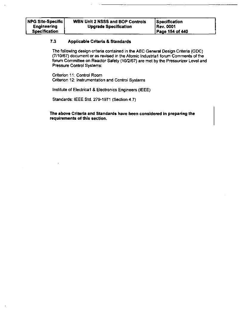
NPG Site-Specific WBN Unit 2 NSSS and BOP Controls SpecificationEngineering Upgrade Specification Rev. 0001Specification Page 154 of 440
7.3 Applicable Criteria & Standards
The following design criteria contained in the AEC General Design Criteria (GDC)(7/10/67) document or as revised in the Atomic Industrial forum Comments of theforum Committee on Reactor Safety (10/2/67) are met by the Pressurizer Level andPressure Control Systems:
Criterion 11: Control Room
Criterion 12: Instrumentation and Control Systems
Institute of Electrical & Electronics Engineers (IEEE)
Standards: IEEE Std. 279-1971 (Section 4.7)
The above Criteria and Standards have been considered in preparing therequirements of this section.
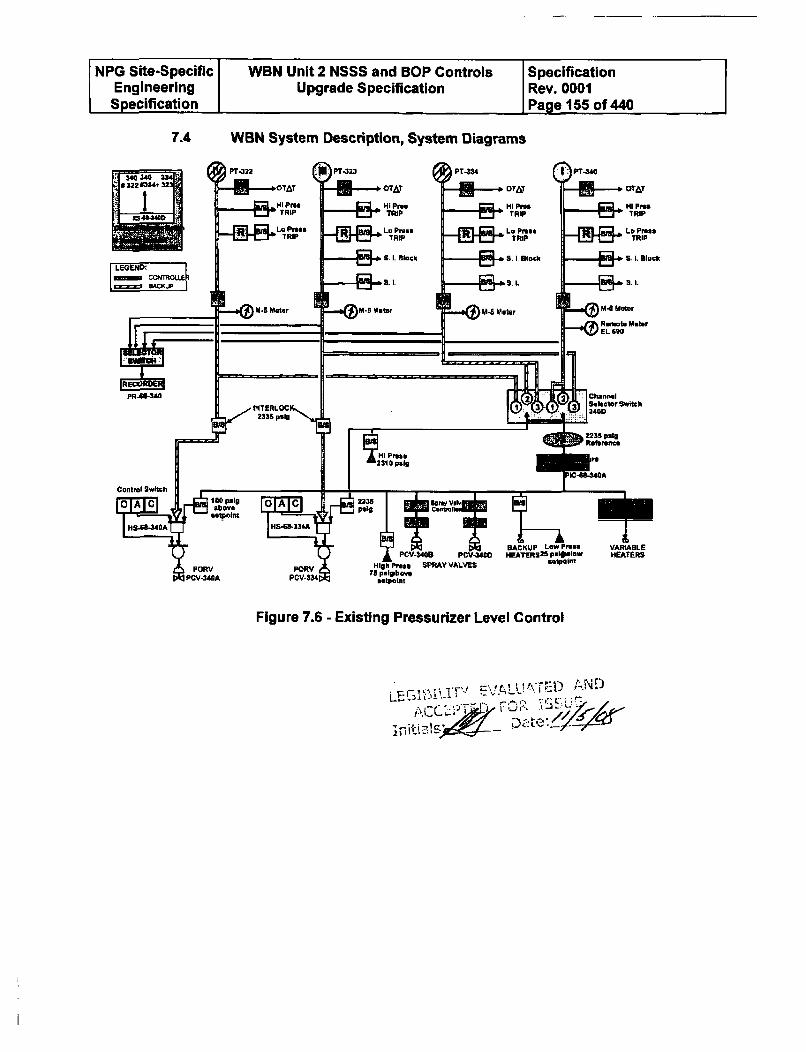
NPG Site-Specific WBN Unit 2 NSSS and BOP Controls SpecificationEngineering Upgrade Specification Rev. 0001Specification Page 155 of 440
7.4 WBN System Description, System Diagrams
Figure 7.6 - Existing Pressurizer Level Control
LEnM~T VLUi:UN
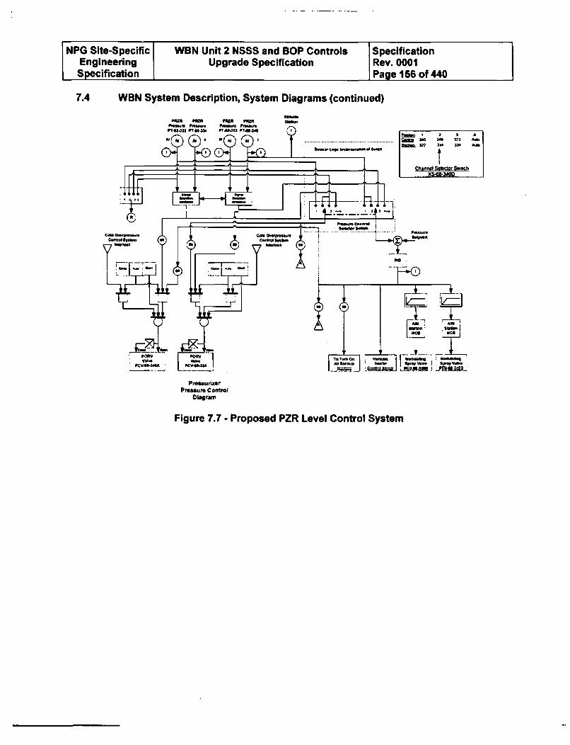
NPG Site-Specific VWBN Unit 2 NSSS and BOP Controls SpecificationEngineering Upgrade Specification Rev. 0001Specification Page 156 of 440
7.4 WBN System Description, System Diagrams (continued)
Paa ; a 2 A....................... ........... NO2 2223 A a
Lqw ~ ~ nl wo .0 AOt is 222 )3N 22 AMs
thre Seecof Sic
PressurizerPressure Control
Diagram
Figure 7.7 - Proposed PZR Level Control System
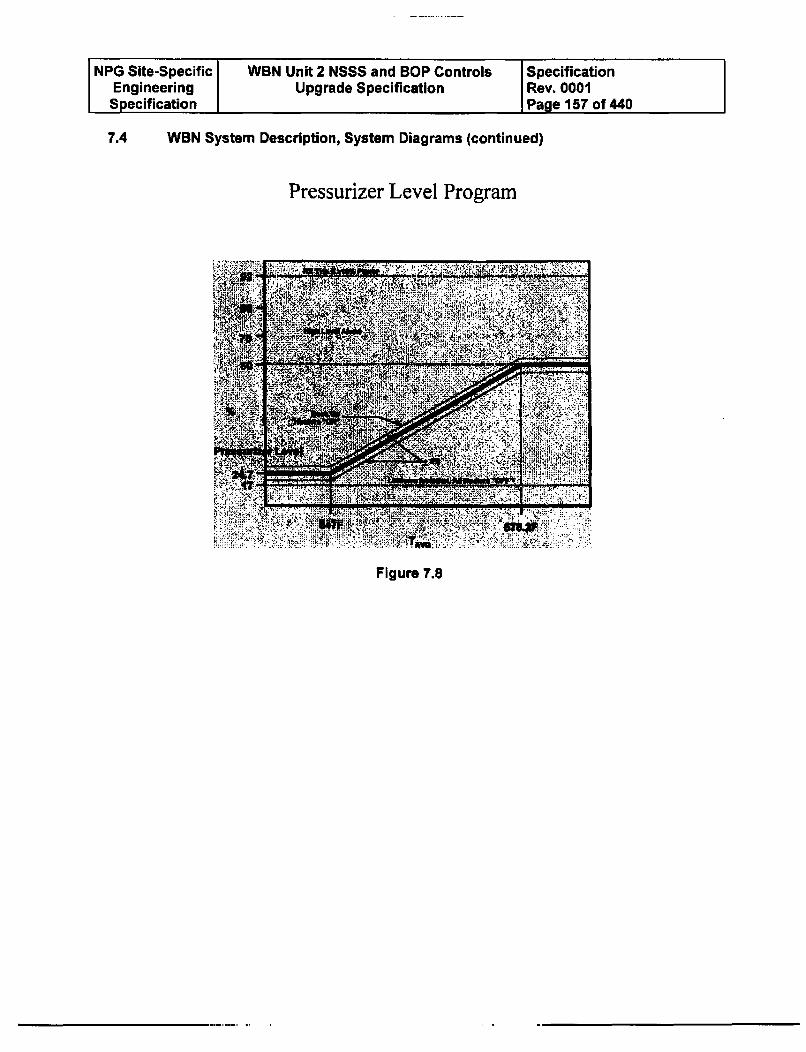
NPG Site-Specific WBN Unit 2 NSSS and BOP Controls SpecificationEngineering Upgrade Specification Rev. 0001Specification Page 157 of 440
7.4 WBN System Description, System Diagrams (continued)
Pressurizer Level Program
Figure 7.8
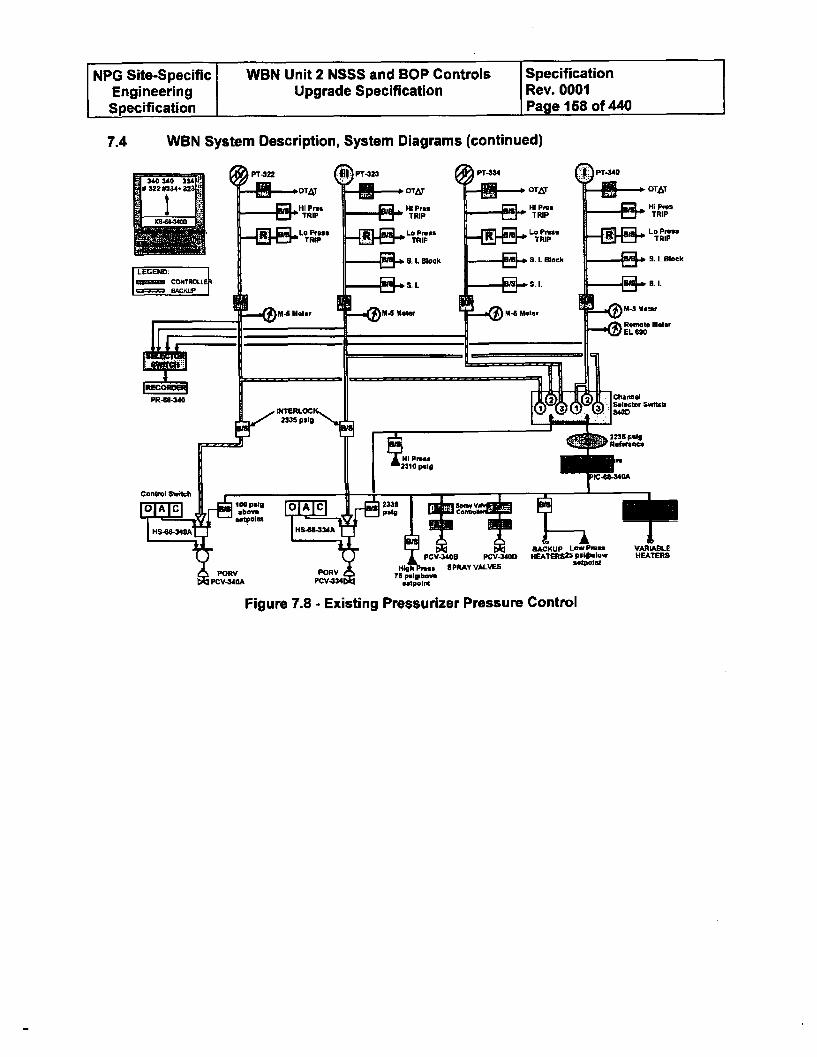
NPG Site-Specific WBN Unit 2 NSSS and BOP Controls SpecificationEngineering Upgrade Specification Rev. 0001Specification Page 158 of 440
7.4 WBN System Description, System Diagrams (continued)
Figure 7.8 - Existing Pressurizer Pressure Control
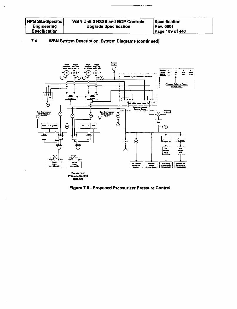
NPG Site-Specific WBN Unit 2 NSSS and BOP Controls SpecificationEngineering Upgrade Specification Rev. 0001Specification Page 159 of 440
7.4 WBN System Description, System Diagrams (continued)
Sa
7- t2 2 3 ~bow. ~ ~ ~ eo Ssw unt0. -f X541340
PreissulerPressur Control
Diagram
Figure 7.9 - Proposed Pressurizer Pressure Control
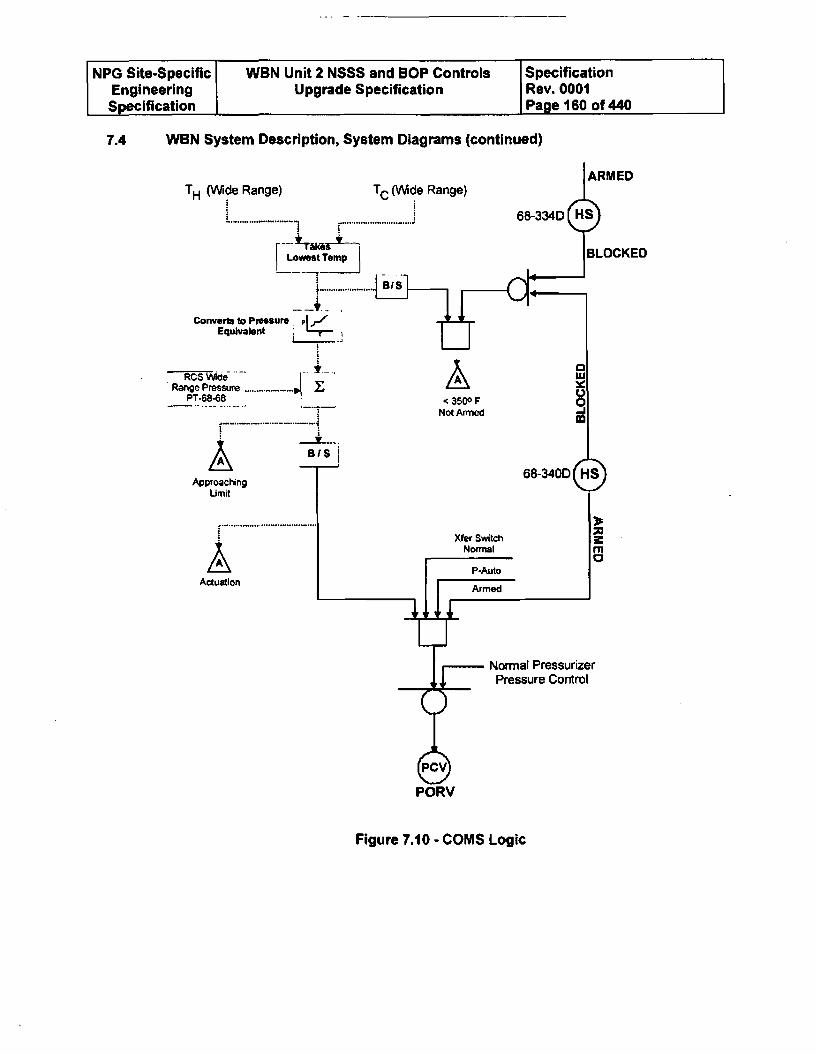
NPG Site-Specific WBN Unit 2 NSSS and SOP Controls SpecificationEngineering Upgrade Specification Rev. 0001Specification Page 160 of 440
7.4 WBN System Description, System Diagrams (continued)
PORV
Figure 7.10 - COMS Logic
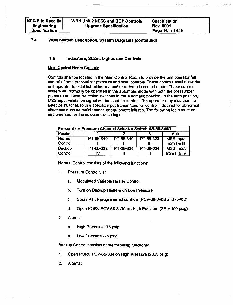
NPG Site-Specific WBN Unit 2 NSSS and BOP Controls SpecificationEngineering Upgrade Specification Rev. 0001Specification Page 161 of 440
7.4 WBN System Description, System Diagrams (continued)
7.5 Indicators, Status Lights. and Controls
Main Control Room Controls
Controls shall be located in the Main Control Room to provide the unit operator fullcontrol of both pressurizer pressure and level controls. These controls shall allow theunit operator to establish either manual or automatic control mode. These controlsystem will normally be operated in the automatic mode with both the pressurizerpressure and level selection switches in the automatic position. In the auto position,MSS input validation signal will be used for control. The operator may also use theselector switches to use specific input transmitters for control if desired for abnormalsituations such as maintenance or equipment failures. The following logic must beimplemented for the selector switch logic.
Pressurizer Pressure Channel Selector Switch XS-68-340DPosition 1 2 3 AutoNormal PT-68-340 PT-68-340 PT-68-323 MSS InputControl I I Ill from I & IIIBackup P1-68-322 PT-68-334 PT-68-334 MSS InputControl IV II II from 11 & IV
Normal Control consists of the following functions:
1. Pressure Control via:
a. Modulated Variable Heater Control
b. Turn on Backup Heaters on Low Pressure
c. Spray Valve programmed controls (PCV-68-340B and -340D)
d. Open PORV PCV-68-340A on High Pressure (SP + 100 psig)
2. Alarms:
a. High Pressure +75 psig
b. Low Pressure -25 psig
Backup Control consists of the following functions:
1. Open PORV PCV-68-334 on High Pressure (2335 psig)
2. Alarms:
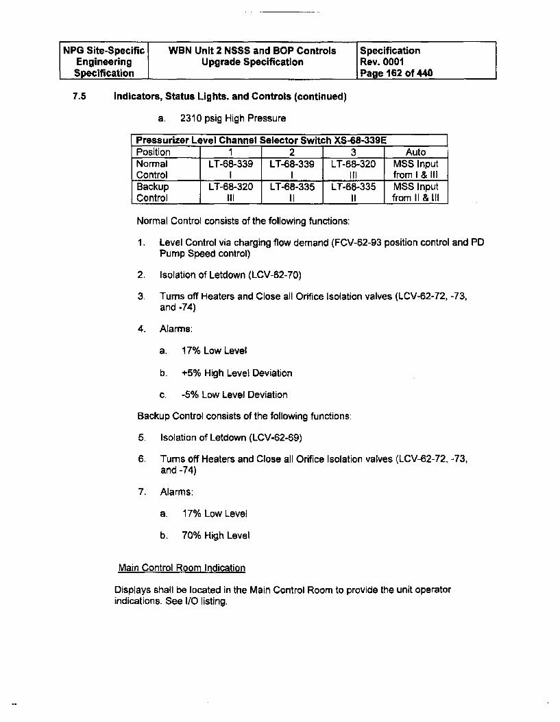
NPG Site-Specific WBN Unit 2 NSSS and BOP Controls SpecificationEngineering Upgrade Specification Rev. 0001Specification Page 162 of 440
7.5 Indicators, Status Lights. and Controls (continued)
a. 2310 psig High Pressure
Pressurizer Level Channel Selector Switch XS-68-339EPosition 1 2 3 AutoNormal LT-68-339 LT-68-339 LT-68-320 MSS InputControl I I III from I & IIIBackup LT-68-320 LT-68-335 LT-68-335 MSS InputControl Ill II II from II & Ill
Normal Control consists of the following functions:
1. Level Control via charging flow demand (FCV-62-93 position control and PDPump Speed control)
2. Isolation of Letdown (LCV-62-70)
3. Turns off Heaters and Close all Orifice Isolation valves (LCV-62-72, -73,and -74)
4. Alarms:
a. 17% Low Level
b. +5% High Level Deviation
c. -5% Low Level Deviation
Backup Control consists of the following functions:
5. Isolation of Letdown (LCV-62-69)
6. Turns off Heaters and Close all Orifice Isolation valves (LCV-62-72, -73,and -74)
7. Alarms:
a. 17% Low Level
b. 70% High Level
Main Control Room Indication
Displays shall be located in the Main Control Room to provide the unit operatorindications. See I/O listing.
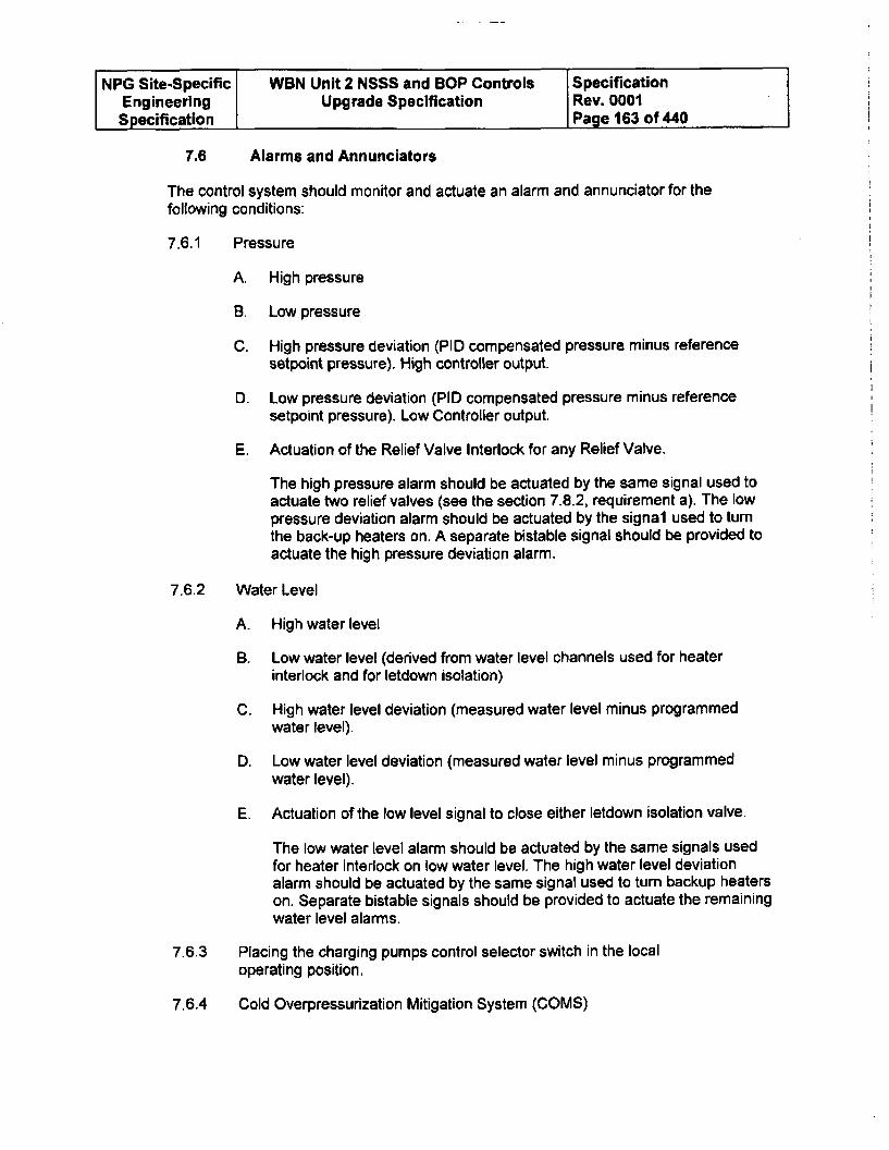
NPG Site-Specific WBN Unit 2 NSSS and BOP Controls SpecificationEngineering Upgrade Specification Rev. 0001Specification Page 163 of 440
7.6 Alarms and Annunciators
The control system should monitor and actuate an alarm and annunciator for thefollowing conditions:
7.6.1 Pressure
A. High pressure
B. Low pressure
C. High pressure deviation (PID compensated pressure minus referencesetpoint pressure). High controller output.
D. Low pressure deviation (PID compensated pressure minus referencesetpoint pressure). Low Controller output.
E. Actuation of the Relief Valve Interlock for any Relief Valve.
The high pressure alarm should be actuated by the same signal used toactuate two relief valves (see the section 7.8.2, requirement a). The lowpressure deviation alarm should be actuated by the signal used to turnthe back-up heaters on. A separate bistable signal should be provided toactuate the high pressure deviation alarm.
7.6.2 Water Level
A. High water level
B. Low water level (derived from water level channels used for heaterinterlock and for letdown isolation)
C. High water level deviation (measured water level minus programmedwater level).
D. Low water level deviation (measured water level minus programmedwater level).
E. Actuation of the low level signal to close either letdown isolation valve.
The low water level alarm should be actuated by the same signals usedfor heater interlock on low water level. The high water level deviationalarm should be actuated by the same signal used to turn backup heaterson. Separate bistable signals should be provided to actuate the remainingwater level alarms.
7.6.3 Placing the charging pumps control selector switch in the localoperating position,
7.6.4 Cold Overpressurization Mitigation System (COMS)
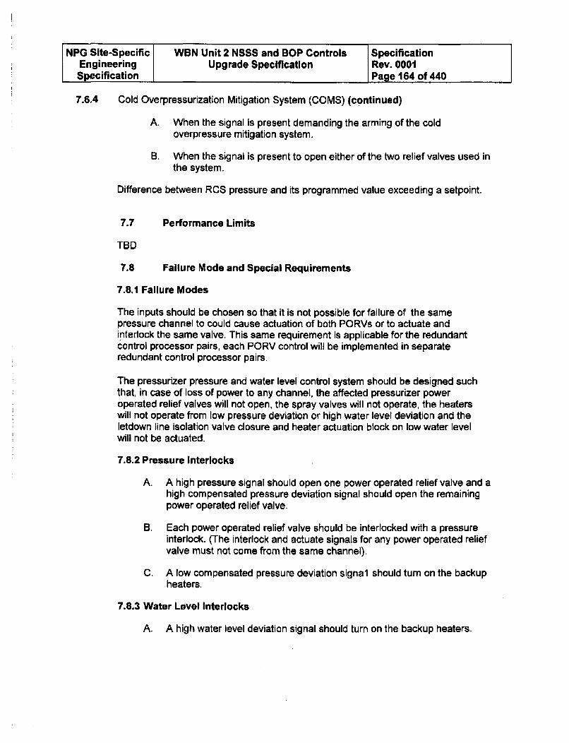
NPG Site-Specific WBN Unit 2 NSSS and BOP Controls SpecificationEngineering Upgrade Specification Rev. 0001Specification Page 164 of 440
7.6.4 Cold Overpressurization Mitigation System (COMS) (continued)
A. When the signal Is present demanding the arming of the coldoverpressure mitigation system.
B. When the signal is present to open either of the two relief valves used inthe system.
Difference between RCS pressure and its programmed value exceeding a setpoint.
7.7 Performance Limits
TBD
7.8 Failure Mode and Special Requirements
7.8.1 Failure Modes
The inputs should be chosen so that it is not possible for failure of the samepressure channel to could cause actuation of both PORVs or to actuate andinterock the same valve. This same requirement is applicable for the redundantcontrol processor pairs, each PORV control will be implemented in separateredundant control processor pairs.
The pressurizer pressure and water level control system should be designed suchthat, in case of loss of power to any channel, the affected pressurizer poweroperated relief valves will not open, the spray valves will not operate, the heaterswill not operate from low pressure deviation or high water level deviation and theletdown line isolation valve closure and heater actuation block on low water levelwill not be actuated.
7.8.2 Pressure Interlocks
A. A high pressure signal should open one power operated relief valve and ahigh compensated pressure deviation signal should open the remainingpower operated relief valve.
B. Each power operated relief valve should be interlocked with a pressureinterlock. (The interlock and actuate signals for any power operated reliefvalve must not come from the same channel).
C. A low compensated pressure deviation signal should turn on the backupheaters.
7.8.3 Water Level Interlocks
A. A high water level deviation signal should turn on the backup heaters.
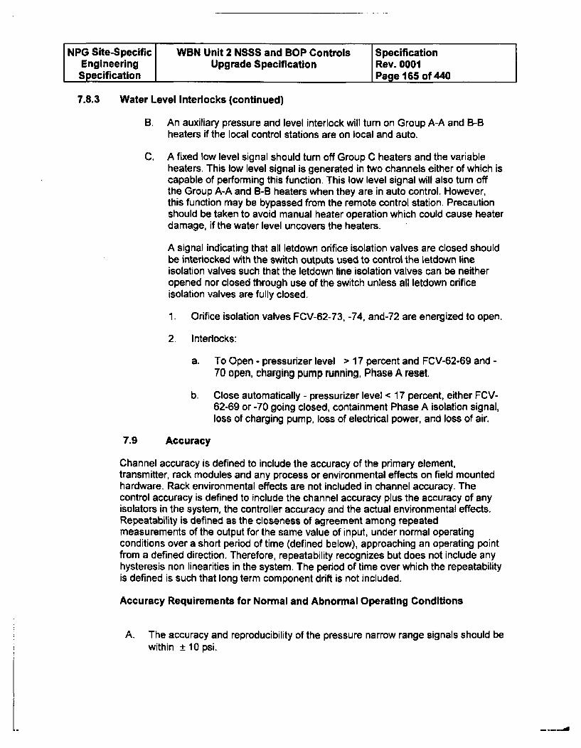
NPG Site-Specific WBN Unit 2 NSSS and BOP Controls SpecificationEngineering Upgrade Specification Rev. 0001Specification Page 165 of 440
7.8.3 Water Level Interlocks (continued)
B. An auxiliary pressure and level interlock will turn on Group A-A and B-Bheaters if the local control stations are on local and auto.
C. A fixed low level signal should turn off Group C heaters and the variableheaters. This low level signal is generated in two channels either of which iscapable of performing this function. This low level signal will also turn offthe Group A-A and B-B heaters when they are in auto control. However,this function may be bypassed from the remote control station. Precautionshould be taken to avoid manual heater operation which could cause heaterdamage, if the water level uncovers the heaters.
A signal indicating that all letdown orifice isolation valves are closed shouldbe interlocked with the switch outputs used to control the letdown lineisolation valves such that the letdown line isolation valves can be neitheropened nor closed through use of the switch unless all letdown orificeisolation valves are fully closed.
1. Orifice isolation valves FCV-62-73, -74, and-72 are energized to open.
2- Interlocks:
a. To Open - pressurizer level > 17 percent and FCV-62-69 and -70 open, charging pump running, Phase A reset.
b. Close automatically - pressurizer level < 17 percent, either FCV-62-69 or -70 going closed, containment Phase A isolation signal,loss of charging pump, loss of electrical power, and loss of air.
7.9 Accuracy
Channel accuracy is defined to include the accuracy of the primary element,transmitter, rack modules and any process or environmental effects on field mountedhardware. Rack environmental effects are not included in channel accuracy. Thecontrol accuracy is defined to include the channel accuracy plus the accuracy of anyisolators in the system, the controller accuracy and the actual environmental effects.Repeatability is defined as the closeness of agreement among repeatedmeasurements of the output for the same value of input, under normal operatingconditions over a short period of time (defined below), approaching an operating pointfrom a defined direction. Therefore, repeatability recognizes but does not include anyhysteresis non linearities in the system. The period of time over which the repeatabilityis defined is such that long term component drift is not included.
Accuracy Requirements for Normal and Abnormal Operating Conditions
A. The accuracy and reproducibility of the pressure narrow range signals should bewithin ± 10 psi.
-.--.-. d
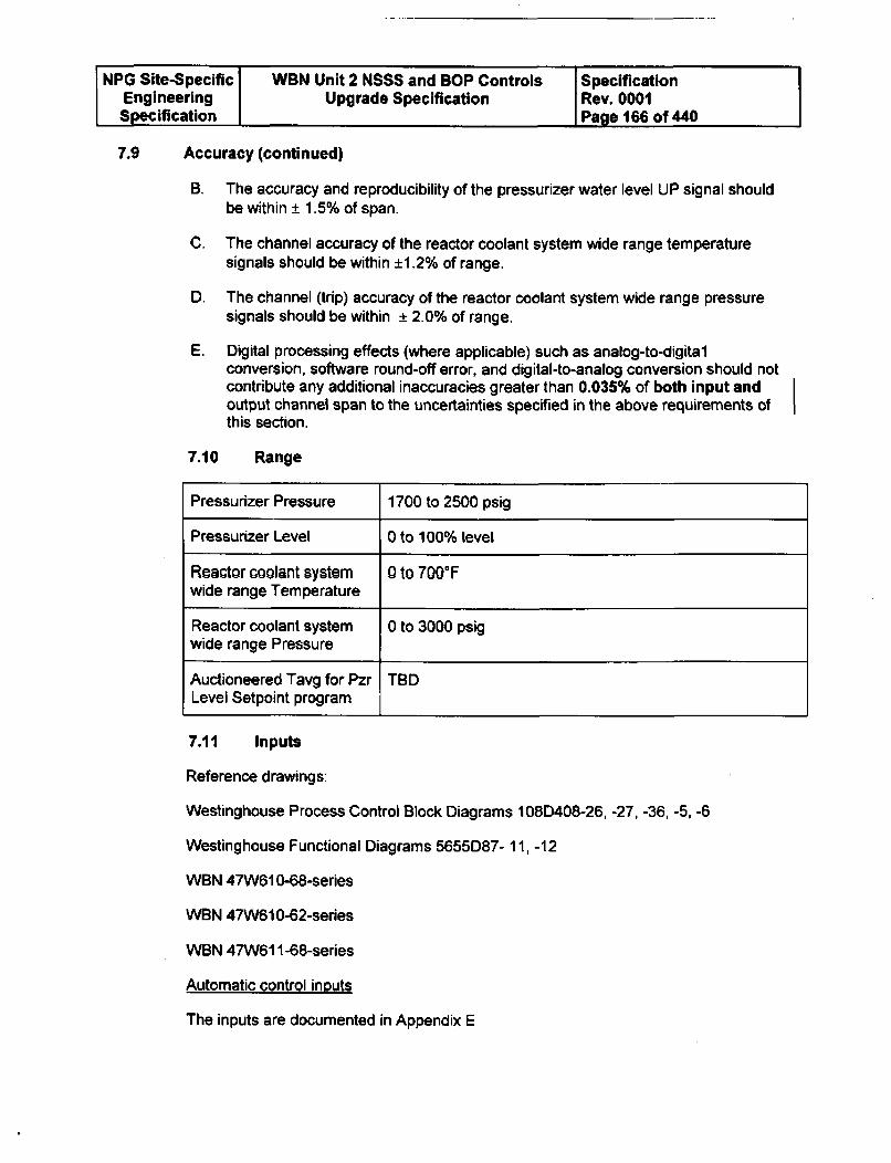
NPG Site-Specific WBN Unit 2 NSSS and BOP Controls SpecificationEngineering Upgrade Specification Rev. 0001Specification Page 166 of 440
7.9 Accuracy (continued)
B. The accuracy and reproducibility of the pressurizer water level UP signal shouldbe within _ 1.5% of span.
C. The channel accuracy of the reactor coolant system wide range temperaturesignals should be within ±1.2% of range.
D. The channel (trip) accuracy of the reactor coolant system wide range pressuresignals should be within ± 2.0% of range.
E. Digital processing effects (where applicable) such as analog-to-digitalconversion, software round-off error, and digital-to-analog conversion should notcontribute any additional inaccuracies greater than 0.035% of both input andoutput channel span to the uncertainties specified in the above requirements ofthis section.
7.10 Range
Pressurizer Pressure 1700 to 2500 psig
Pressurizer Level 0 to 100% level
Reactor coolant system 0 to 700MFwide range Temperature
Reactor coolant system 0 to 3000 psigwide range Pressure
Auctioneered Tavg for Pzr TBDLevel Setpoint program
7.11 Inputs
Reference drawings:
Westinghouse Process Control Block Diagrams 108D408-26, -27, -36, -5, -6
Westinghouse Functional Diagrams 5655D87- 11, -12
WBN 47W610-68-series
WBN 47W610-62-series
WBN 47W611-68-series
Automatic control inputs
The inputs are documented in Appendix E
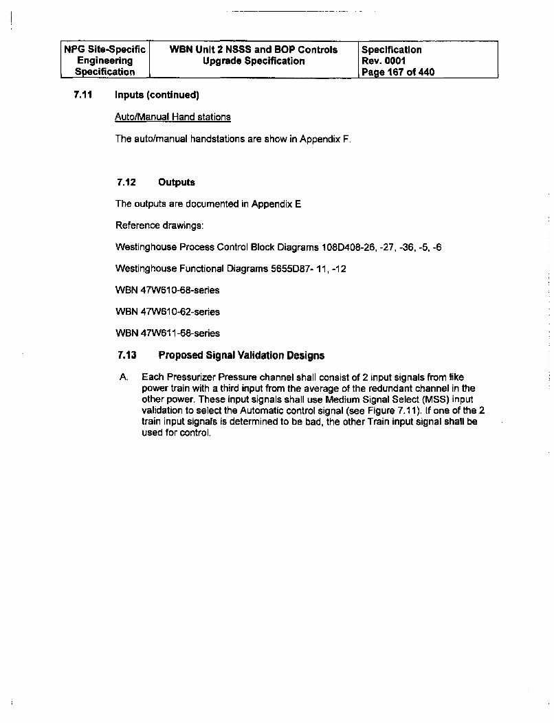
NPG Site-Specific WBN Unit 2 NSSS and BOP Controls SpecificationEngineering Upgrade Specification Rev. 0001Specification Page 167 of 440
7.11 Inputs (continued)
AutolManual Hand stations
The auto/manual handstations are show in Appendix F.
7.12 Outputs
The outputs are documented in Appendix E
Reference drawings:
Westinghouse Process Control Block Diagrams 108D408-26, -27, -36, -5, -6
Westinghouse Functional Diagrams 5655D87- 11, -12
WBN 47W61 0-68-sedes
WBN 47W610-62-series
WBN 47W611-68-series
7.13 Proposed Signal Validation Designs
A. Each Pressurizer Pressure channel shall consist of 2 input signals from likepower train with a third input from the average of the redundant channel in theother power. These input signals shall use Medium Signal Select (MSS) inputvalidation to select the Automatic control signal (see Figure 7.11). If one of the 2train input signals is determined to be bad, the other Train input signal shall beused for control.
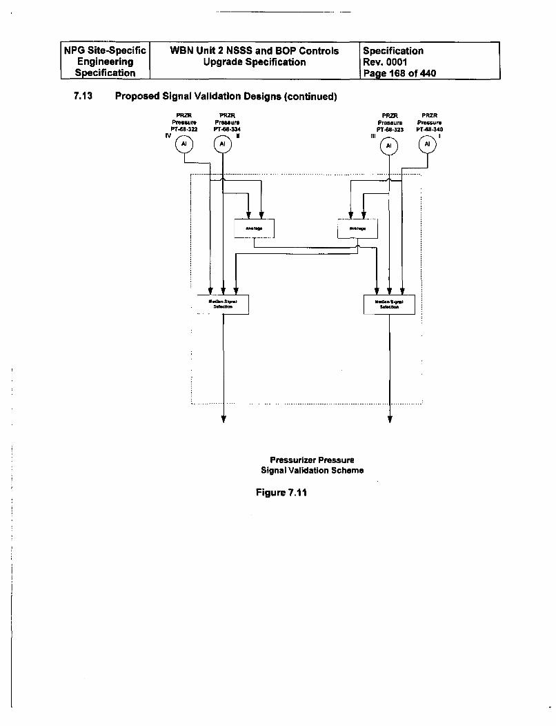
NPG Site-Specific WBN Unit 2 NSSS and BOP Controls SpecificationEngineering Upgrade Specification Rev. 0001Specification Page 168 of 440
7.13 Proposed Signal Validation Designs (continued)
PRZR PRZR PRZR PRZRPresure Pressure
III
Pressurizer PressureSignal Validation Scheme
Figure 7.11
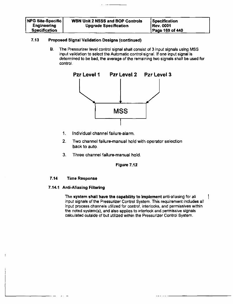
NPG Site-Specific WBN Unit 2 NSSS and BOP Controls SpecificationEngineering Upgrade Specification Rev. 0001Specification Page 169 of 440
7.13 Proposed Signal Validation Designs (continued)
B. The Pressurizer level control signal shall consist of 3 input signals using MSSinput validation to select the Automatic control signal. If one input signal isdetermined to be bad, the average of the remaining two signals shall be used forcontrol.
Pzr Level I Pzr Level 2 Pzr Level 3
1. Individual channel failure-alarm.
2. Two channel failure-manual hold with operator selectionback to auto.
3. Three channel failure-manual hold.
Figure 7.12
7.14 Time Response
7.14.1 Anti-Aliasing Filtering
The system shall have the capability to implement anti-aliasing for allinput signals of the Pressurizer Control System. This requirement includes allinput process channels utilized for control, interlocks, and permissives withinthe noted system(s), and also applies to interlock and permissive signalscalculated outside of but utilized within the Pressurizer Control System.
I
NPG Site-Specific WBN Unit 2 NSSS and BOP Controls SpecificationEngineering Upgrade Specification Rev. 0001Specification Page 170 of 440
7.14.2 Control Processors Response Time
The control processor response time (from the control system's inputmodule/s to output module/s including control system processing time) for allinput signals of the Pressurizer Control System shall not exceed 250 milli-seconds. This requirement includes all input process channels utilized forcontrol, interlocks, and permissives within the noted system(s), and alsoapplies to interlock and permissive signals calculated outside of but utilizedwithin Pressurizer Control System. This requirement includes all modulatingcontrol signals, bistable logic (on/off) control signals, mode signals, andsignals to the main control board (indication, status, and alarm/annunciators).
7.14.3 Communication Response Time between ControlProcessors
Communication between different Control Processor pairs shall not exceed500 milli-seconds for signals involved in closed loop control for thisfunction.
7.14.4 Manual Control Response
The total delay for all manual component control signals of Pressurizer
Control System shall be no greater than 1 second.
7.15 Controller Reset Windup and Recovery Characteristics
The control system shall not be susceptible hardware or software controller resetwindup. After the out-of-range signal causing the overload returns from the overloadcondition, all component units of the system must recover from the saturated conditionand return to their correct output values (within normal error limits) within 1 second.During recovery from overload, the output of all affected component units mustprogress smoothly from the saturated value to the correct value without oscillation orovershoot larger than 1% (peak to peak) of channel range exclusive of the theoreticalamplification of lead/lag and rate/lag units. The I second recovery time specifiedabove need be met only when all externally adjustable time delays are set to 0.0. Therequirements on oscillation and overshoot should be met even with all externallyadjustable time delays set to 0.0.
7.16 Noise Levels
The root mean square noise should be limited to 1.2% of output span in all channels.The noise limitation does not apply to process signal noise, e.g., fluctuations inapplicable process variables, but should apply to all noise generated from detectingthe signal onward. Where applicable, the requirement should be met with all lead, lag,and filter time constants set to 0.0 and module gains set to 1.
7.17 Programmed Functions
Pressurizer Pressure Functions
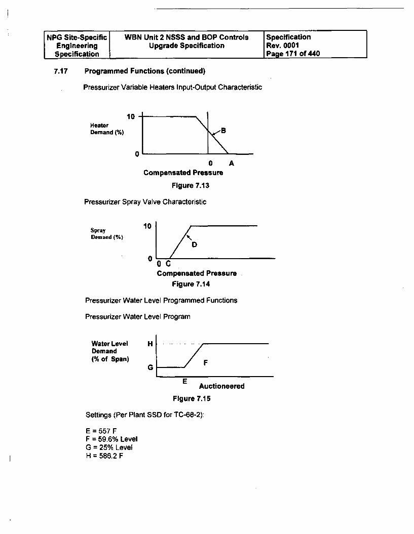
NPG Site-Specific WBN Unit 2 NSSS and BOP Controls SpecificationEngineering Upgrade Specification Rev. 0001Specification Page 171 of 440
7.17 Programmed Functions (continued)
Pressurizer Variable Heaters Input-Output Characteristic
10HeaterDemand (%)
0'
0Compensated Pressure
Figure 7.13
Pressurizer Spray Valve Characteristic
A
Spray 10
Demand (%)
0 //D00C
Compensated Pressure
Figure 7.14
Pressurizer Water Level Programmed Functions
Pressurizer Water Level Program
Water LevelDemand(% of Span)
H
G F
E Auctioneered
Figure 7.15
Settings (Per Plant SSD for TC-68-2):
E = 557 FF = 59.6% LevelG = 25% LevelH = 586.2 F
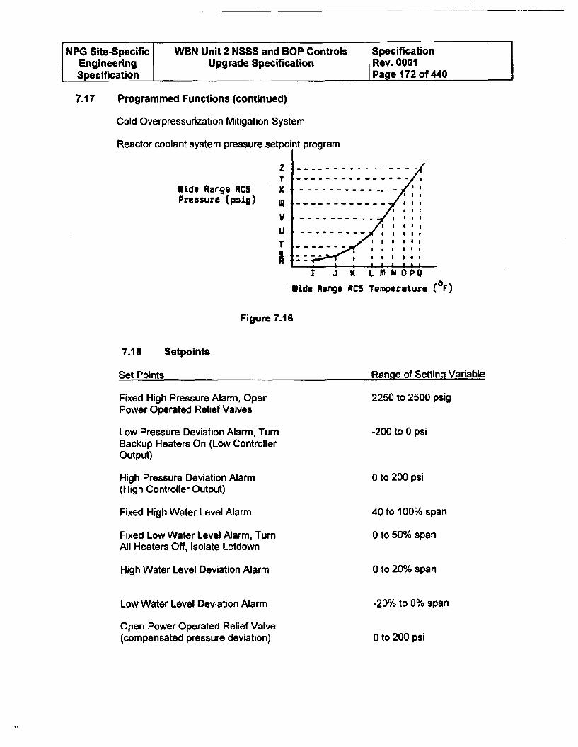
NPG Site-Specific WBN Unit 2 NSSS and BOP Controls SpecificationEngineering Upgrade Specification Rev. 0001Specification Page 172 of 440
7.17 Programmed Functions (continued)
Cold Overpressurization Mitigation System
Reactor coolant system pressure setpoint program
zY
lide Range RCS XPressure (psig) * - - -- - --------
V------------- Il
U------------- III
TI - -- --
I I *, 541J
I J K L M N 0POWide Range RCS Temperature (rF)
Figure 7.16
7.18
Set Points
Setpoints
Ranae of Settina Variable
Fixed High Pressure Alarm, OpenPower Operated Relief Valves
Low Pressure Deviation Alarm, TurnBackup Heaters On (Low ControllerOutput)
High Pressure Deviation Alarm(High Controller Output)
Fixed High Water Level Alarm
Fixed Low Water Level Alarm, TurnAll Heaters Off, Isolate Letdown
High Water Level Deviation Alarm
Low Water Level Deviation Alarm
Open Power Operated Relief Valve(compensated pressure deviation)
2250 to 2500 psig
-200 to 0 psi
0 to 200 psi
40 to 100% span
0 to 50% span
0 to 20% span
-20% to 0% span
0 to 200 psi
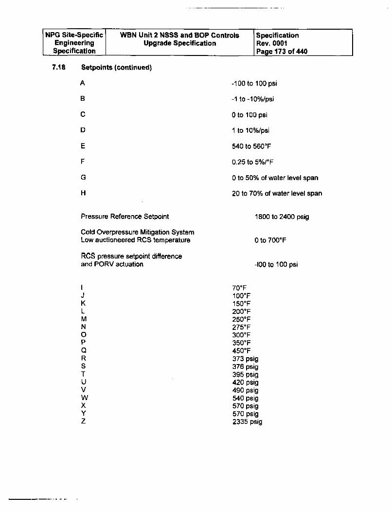
NPG Site-Specific VWBN Unit 2 NSSS and BOP Controls SpecificationEngineering Upgrade Specification Rev. 0001Specification Page 173 of 440
7.18 Setpoints (continued)
A
B
C
D
E
F
G
H
Pressure Reference Setpoint
Cold Overpressure Mitigation SystemLow auctioneered RCS temperature
RCS pressure setpoint differenceand PORV actuation
-100 to 100 psi
-1 to -10%/psi
0 to 100 psi
1 to 10%/psi
540 to 5600 F
0.25 to 5%/°F
0 to 50% of water level span
20 to 70% of water level span
1800 to 2400 psig
0 to 700F
-100 to 100 psi
700F1OO°F150°F200TF250°F275°F300°F3500 F4500 F373 psig376 psig395 psig420 psig490 psig540 psig570 psig570 psig2335 psig
J
KLMN0PQRSTUVWxYz

NPG Site-Specific WBN Unit 2 NSSS and BOP Controls SpecificationEngineering Upgrade Specification Rev. 0001Specification Page 174 of 440
7.19 Requirements for Test and Calibration
The Pressurizer Pressure and Heater Level Control System is not a protection systemand, therefore, does not require the capability of being tested at power. Surveillancetesting will be performed for COMS prior to plant heatup and cooldown above andbelow 350F (Mode 4).
7.20 Applicable Criteria & Standards
The following criteria apply to this system.
7.20.1 AEC General Design Criteria (GDC) (2/20/71): GDC 13, 19, 24
7.20.2 Institute of Electrical & Electronics Engineers (IEEE) Standards:IEEE Std. 279-1971 (Section 4.7)
The above Criteria and Standards have been considered in preparing therequirements of this section
8.0 BA BLENDER CONTROLS INTRODUCTION
8.1 Overview
A Boric Acid Blend Control System shall be provided for WBN Unit 2. The ControlSystem shall be complete with all necessary hardware and software, system logic,system graphics, and power supplies meeting the functional requirements of thisspecification.
8.2 Boric Acid Blender Control System Upgrade
The scope of this upgrade consists of replacement of the existing NSSS Boric AcidBlender control system located in the NSSS control rack groupings. The existingcontrols are presently located in Rack 15 in the AIR with control stations located in theMCR. Remote I/O modules mounted in a 19 inch nest will be placed in the existingFoxboro cabinets (will use the baseplate for Racks 14/15/16). The associated AnalogOutputs are not deemed Critical signals and do not require redundant output modules Iwith passive switching for the final device. The control system outputs that presentlyfeed through their individual handstations will be changed to eliminate the Handstation I(HS) as a single point of failure. Remote 1/0 will be located in MCR. Any analogoutput devices will be changed out from 10 to 50 mA to 4 to 20 mA loops. Any 10 to50 mA I/P converters will be changed out to a 4 to 20 mA type (to be supplied byTVA).
The following system graphics, at a minimum, shall be supplied. The Offerer shall listand describe the number and type of graphics that are proposed. Offerer shouldprovide cost of additional screens.
System Mimics
An additional mimic will be developed for Boric Acid Blender Controls. This mimic willconsist of a Boric Acid Blender overview with Boric Flow, Primary Water Flow,Deviation Alarms, the Batch counters and Flow controllers for each flow loop, Modeselection with Status indication, and trending information
8.2.1 Critical Control System Signals
Non-critical Control Signals
One process input for each boric acid and primary water flow control loop will beprovided. Gross failure detection shall be implemented and shall transfer the controlsystem to manual upon detection of an input failure.
System Hazards Analysis
The Offerer shall include the Boric Acid control system into the Hazards Analysis eventhough the inputs and outputs are single points of failure.
Some of the most important objectives of the failure study include:
0 The potential for over or under shooting boration and dilution.
NPG Site-Specific WBN Unit 2 NSSS and BOP Controls SpecificationEngineering Upgrade Specification Rev. 0001Specification Page 176 of 440
8.2.2 System Description and Operation
The makeup control portion of the Chemical Volume and Control System (CVCS)provides boric acid solution and distillate to the RCS. It consists of equipment and agroup of instruments arranged to provide a manually preselected makeup compositionto the charging pump suction or the VCT. Makeup control functions are those ofmaintaining desired operating fluid inventory in the VCT and adjusting RCS boronconcentration for reactivity control.
The boric acid batching tank is used to prepare fresh boric acid solution. The BATsstore this solution. Initial filling and makeup quantities of the required percent boricacid solution are prepared in the batching tank by dissolving boric acid crystals in hotwater.
The batch of boric acid is transferred to the BATs by the boric acid transfer pumps.There are 2 two-speed boric acid transfer pumps per unit. One pump is normally runon slow speed to provide BAT recirculation. The recirculation flow is either at a fixedrate or at a rate set by the operator. The second pump of each pair can be aligned tothe third BAT and is considered to be a standby pump, with service being transferredas operation requires.
A primary water pump, taking suction from the Primary Water Storage Tank (PWST),provides flow to the boric acid blender where mixing with boric acid occurs. Themixture is then directed to the suction of the charging pumps or is sprayed into theVolume Control Tank (VCT).
8.2.3 Modes of Operation
Reactor makeup control system can be set for the following modes of operation:automatic makeup, dilution, alternate dilution, boration, and manual. These modesprovide flow control signals to the boric acid and primary water makeup valves. Theinterface with the C&MS consists of input signals for boric acid and primary water flowrates (4-20 ma) and output control signals to the associated control valves (FCV-62-140 and -143). The C&MS shall interface with remote A/M controllers (FCV-62-139and -142) located on the MCB. The PID control function for each controller is asoftware feature. Refer to Appendix E for listing of interfaces.
The C&MS shall compare the regulated flow rate for the boric acid and primary waterto the selected control setpoint. Upon detection of a high or low deviation, the C&MSinitiates an alarm (bistable) which actuates a MCR annunciation.
The C&MS shall develop control logic based upon discrete inputs for the Boric acidblender selector switch. Specifically, the C&MS shall receive discrete inputs when theselector switch is placed in "Auto Makeup" mode and "Dilute or Alternate Dilute"modes. When the selector switch is in either mode the primary water controller uses afixed setpoint value.
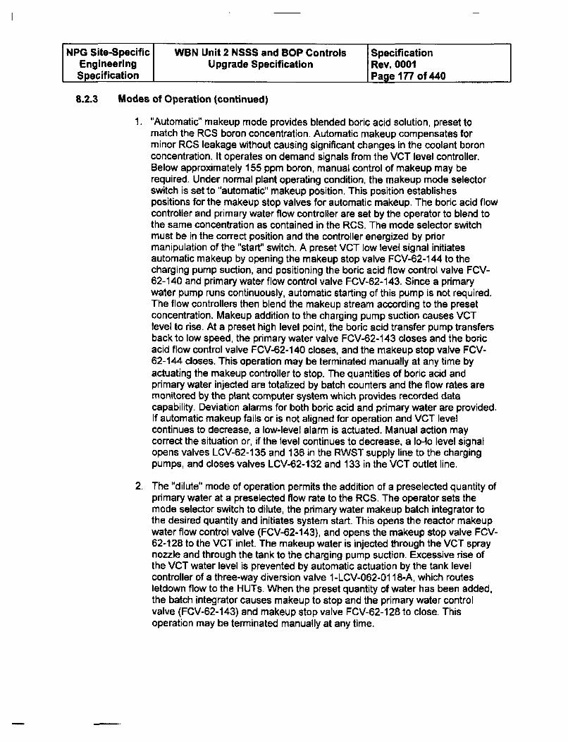
NPG Site-Specific WBN Unit 2 NSSS and BOP Controls SpecificationEngineering Upgrade Specification Rev. 0001Specification Page 177 of 440
8.2.3 Modes of Operation (continued)
1. "Automatic" makeup mode provides blended boric acid solution, preset tomatch the RCS boron concentration. Automatic makeup compensates forminor RCS leakage without causing significant changes in the coolant boronconcentration. It operates on demand signals from the VCT level controller.Below approximately 155 ppm boron, manual control of makeup may berequired. Under normal plant operating condition, the makeup mode selectorswitch is set to "automatic" makeup position. This position establishespositions for the makeup stop valves for automatic makeup. The boric acid flowcontroller and primary water flow controller are set by the operator to blend tothe same concentration as contained in the RCS. The mode selector switchmust be in the correct position and the controller energized by priormanipulation of the "start' switch. A preset VCT low level signal initiatesautomatic makeup by opening the makeup stop valve FCV-62-144 to thecharging pump suction, and positioning the boric acid flow control valve FCV-62-140 and primary water flow control valve FCV-62-143. Since a primarywater pump runs continuously, automatic starting of this pump is not required.The flow controllers then blend the makeup stream according to the presetconcentration. Makeup addition to the charging pump suction causes VCTlevel to rise. At a preset high level point, the boric acid transfer pump transfersback to low speed, the primary water valve FCV-62-143 closes and the boricacid flow control valve FCV-62-140 closes, and the makeup stop valve FCV-62-144 closes. This operation may be terminated manually at any time byactuating the makeup controller to stop. The quantities of boric acid andprimary water injected are totalized by batch counters and the flow rates aremonitored by the plant computer system which provides recorded datacapability. Deviation alarms for both boric acid and primary water are provided.If automatic makeup fails or is not aligned for operation and VCT levelcontinues to decrease, a low-level alarm is actuated. Manual action maycorrect the situation or, if the level continues to decrease, a Io-io level signalopens valves LCV-62-135 and 136 in the RWST supply line to the chargingpumps, and closes valves LCV-62-132 and 133 in the VCT outlet line.
2. The "dilute" mode of operation permits the addition of a preselected quantity ofprimary water at a preselected flow rate to the RCS. The operator sets themode selector switch to dilute, the primary water makeup batch integrator tothe desired quantity and initiates system start. This opens the reactor makeupwater flow control valve (FCV-62-143), and opens the makeup stop valve FCV-62-128 to the VCT inlet. The makeup water is injected through the VCT spraynozzle and through the tank to the charging pump suction. Excessive rise ofthe VCT water level is prevented by automatic actuation by the tank levelcontroller of a three-way diversion valve 1 -LCV-062-0118-A, which routesletdown flow to the HUTs. When the preset quantity of water has been added,the batch integrator causes makeup to stop and the primary water controlvalve (FCV-62-143) and makeup stop valve FCV-62-128 to close. Thisoperation may be terminated manually at any time.
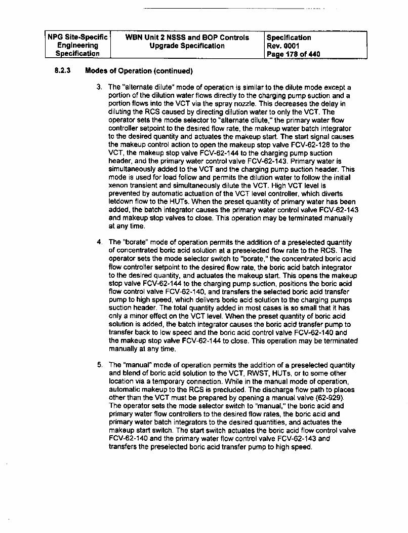
NPG Site-Specific WBN Unit 2 NSSS and BOP Controls SpecificationEngineering Upgrade Specification Rev. 0001Specification Page 178 of 440
8.2.3 Modes of Operation (continued)
3. The "alternate dilute" mode of operation is similar to the dilute mode except aportion of the dilution water flows directly to the charging pump suction and aportion flows into the VCT via the spray nozzle. This decreases the delay indiluting the RCS caused by directing dilution water to only the VCT. Theoperator sets the mode selector to "alternate dilute," the primary water flowcontroller setpoint to the desired flow rate, the makeup water batch integratorto the desired quantity and actuates the makeup start. The start signal causesthe makeup control action to open the makeup stop valve FCV-62-128 to theVCT, the makeup stop valve FCV-62-144 to the charging pump suctionheader, and the primary water control valve FCV-62-143. Primary water issimultaneously added to the VCT and the charging pump suction header. Thismode is used for load follow and permits the dilution water to follow the initialxenon transient and simultaneously dilute the VCT. High VCT level isprevented by automatic actuation of the VCT level controller, which divertsletdown flow to the HUTs. When the preset quantity of primary water has beenadded, the batch integrator causes the primary water control valve FCV-62-143and makeup stop valves to close. This operation may be terminated manuallyat any time.
4. The "borate" mode of operation permits the addition of a preselected quantityof concentrated boric acid solution at a preselected flow rate to the RCS. Theoperator sets the mode selector switch to "borate," the concentrated boric acidflow controller setpoint to the desired flow rate, the boric acid batch integratorto the desired quantity, and actuates the makeup start. This opens the makeupstop valve FCV-62-144 to the charging pump suction, positions the boric acidflow control valve FCV-62-140, and transfers the selected boric acid transferpump to high speed, which delivers boric acid solution to the charging pumpssuction header. The total quantity added in most cases is so small that it hasonly a minor effect on the VCT level. When the preset quantity of boric acidsolution is added, the batch integrator causes the boric acid transfer pump totransfer back to low speed and the boric acid control valve FCV-62-140 andthe makeup stop valve FCV-62-144 to close. This operation may be terminatedmanually at any time.
5. The "manual" mode of operation permits the addition of a preselected quantityand blend of boric acid solution to the VCT, RWST, HUTs, or to some otherlocation via a temporary connection. While in the manual mode of operation,automatic makeup to the RCS is precluded. The discharge flow path to placesother than the VCT must be prepared by opening a manual valve (62-929).The operator sets the mode selector switch to "manual," the boric acid andprimary water flow controllers to the desired flow rates, the boric acid andprimary water batch integrators to the desired quantities, and actuates themakeup start switch. The start switch actuates the boric acid flow control valveFCV-62-140 and the primary water flow control valve FCV-62-143 andtransfers the preselected boric acid transfer pump to high speed.
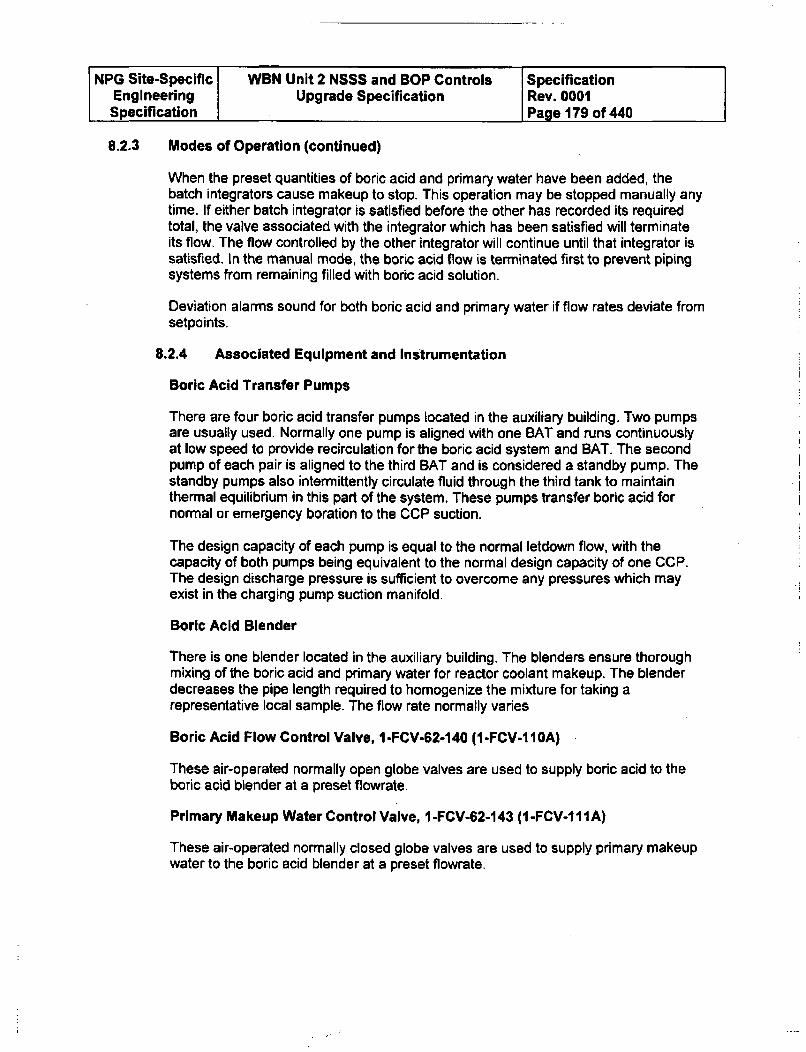
NPG Site-Specific WBN Unit 2 NSSS and BOP Controls SpecificationEngineering Upgrade Specification Rev. 0001Specification Page 179 of 440
8.2.3 Modes of Operation (continued)
When the preset quantities of boric acid and primary water have been added, thebatch integrators cause makeup to stop. This operation may be stopped manually anytime. If either batch integrator is satisfied before the other has recorded its requiredtotal, the valve associated with the integrator which has been satisfied will terminateits flow. The flow controlled by the other integrator will continue until that integrator issatisfied. In the manual mode, the boric acid flow is terminated first to prevent pipingsystems from remaining filled with boric acid solution.
Deviation alarms sound for both boric acid and primary water if flow rates deviate fromsetpoints.
8.2.4 Associated Equipment and Instrumentation
Boric Acid Transfer Pumps
There are four boric acid transfer pumps located in the auxiliary building. Two pumpsare usually used. Normally one pump is aligned with one BAT and runs continuouslyat low speed to provide recirculation for the boric acid system and BAT. The secondpump of each pair is aligned to the third BAT and is considered a standby pump. Thestandby pumps also intermittently circulate fluid through the third tank to maintainthermal equilibrium in this part of the system. These pumps transfer boric acid fornormal or emergency boration to the CCP suction.
The design capacity of each pump is equal to the normal letdown flow, with thecapacity of both pumps being equivalent to the normal design capacity of one CCP.The design discharge pressure is sufficient to overcome any pressures which mayexist in the charging pump suction manifold.
Boric Acid Blender
There is one blender located in the auxiliary building. The blenders ensure thoroughmixing of the boric acid and primary water for reactor coolant makeup. The blenderdecreases the pipe length required to homogenize the mixture for taking arepresentative local sample. The flow rate normally varies
Boric Acid Flow Control Valve, I -FCV-62-140 (1 -FCV.I OA)
These air-operated normally open globe valves are used to supply boric acid to theboric acid blender at a preset flowrate.
Primary Makeup Water Control Valve, 1-FCV-62-143 (1-FCV-111A)
These air-operated normally closed globe valves are used to supply primary makeupwater to the boric acid blender at a preset flowrate.
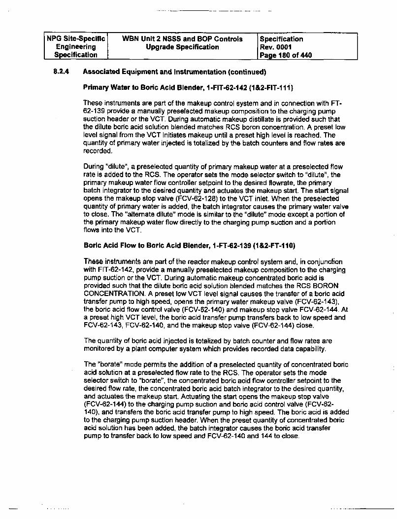
NPG Site-Specific WBN Unit 2 NSSS and BOP Controls SpecificationEngineering Upgrade Specification Rev. 0001Specification Page 180 of 440
8.2.4 Associated Equipment and Instrumentation (continued)
Primary Water to Boric Acid Blender, 1 -FIT-62-142 (1&2-FIT-1 11)
These instruments are part of the makeup control system and in connection with FT-62-139 provide a manually preselected makeup composition to the charging pumpsuction header or the VCT. During automatic makeup distillate is provided such thatthe dilute boric acid solution blended matches RCS boron concentration. A preset lowlevel signal from the VCT initiates makeup until a preset high level is reached. Thequantity of primary water injected is totalized by the batch counters and flow rates arerecorded.
During "dilute", a preselected quantity of primary makeup water at a preselected flowrate is added to the RCS. The operator sets the mode selector switch to "dilute", theprimary makeup water flow controller setpoint to the desired flowrate, the primarybatch integrator to the desired quantity and actuates the makeup start. The start signalopens the makeup stop valve (FCV-62-128) to the VCT inlet. When the preselectedquantity of primary water is added, the batch integrator causes the primary water valveto close. The "alternate dilute" mode is similar to the "dilute" mode except a portion ofthe primary makeup water flow directly to the charging pump suction and a portionflows into the VCT.
Boric Acid Flow to Boric Acid Blender, 1-FT-62-139 (1&2-FT-110)
These instrumerts are part of the reactor makeup control system and, in conjunctionwith FIT-62-142, provide a manually preselected makeup composition to the chargingpump suction or the VCT. During automatic makeup concentrated boric acid isprovided such that the dilute boric acid solution blended matches the RCS BORONCONCENTRATION. A preset low VCT level signal causes the transfer of a boric acidtransfer pump to high speed, opens the primary water makeup valve (FCV-62-143),the boric acid flow control valve (FCV-62-140) and makeup stop valve FCV-62-144. Ata preset high VCT level, the boric acid transfer pump transfers back to low speed andFCV-62-143, FCV-62-140, and the makeup stop valve (FCV-62-144) close.
The quantity of boric acid injected is totalized by batch counter and flow rates aremonitored by a plant computer system which provides recorded data capability.
The "borate" mode permits the addition of a preselected quantity of concentrated boricacid solution at a preselected flow rate to the RCS. The operator sets the modeselector switch to "borate", the concentrated boric acid flow controller setpoint to thedesired flow rate, the concentrated boric acid batch integrator to the desired quantity,and actuates the makeup start. Actuating the start opens the makeup stop valve(FCV-62-144) to the charging pump suction and boric acid control valve (FCV-62-140), and transfers the boric acid transfer pump to high speed. The boric acid is addedto the charging pump suction header. When the preset quantity of concentrated boricacid solution has been added, the batch integrator causes the boric acid transferpump to transfer back to low speed and FCV-62-140 and 144 to dose.
NPG Site-Specific WBN Unit 2 NSSS and BOP Controls SpecificationEngineering Upgrade Specification Rev. 0001Specification Page 181 of 440
8.2.5 Makeup System Operating Precautions
1. Except during boration or dilution operations, the makeup system should beoperated in the automatic mode with the boron concentration setting adjusted tomatch RCS concentration.
2. Changes in reactor coolant chemistry should be anticipated whenever the boronconcentration is altered. During long term dilution, the reactor coolant shouldperiodically be checked to ensure compliance with the chemistry specifications.
3. RCS dilution may be performed only when the reactor is substantially subcritical orwith the control rods above their insertion limit.
4. The effects of boration or dilution while the reactor is subcritical must be monitoredby observing the source range count rate. If the count rate increases at anunexpected rate, the operation must be stopped.
5. The effects of boration and dilution at power must be monitored by observing theresulting control rod bank movement and changes in coolant average temperature.The operation must be stopped if the control bank movement is in the wrongdirection.
6. When operating at a reduced load, it is preferable to adjust boron concentration sothat the control rods are maintained in a position that facilitates responses to loadincreases within the restraints of constant axial offset control.
7. PZR boron concentration should not be less than the concentration in the RCSloops by more than 50 ppm. PZR spray should be operated to equalize theconcentrations. Operation of the heaters will cause automatic operation of thesprays.
8. Operation of the reactor makeup system should be avoided in the dilute mode andthe alternate dilute mode with a primary water flow controller setting of 5-10% dueto the potential for controller oscillations.
8.2.6 Malfunction of Reactor Makeup Control
Indication of possible reactor makeup malfunctions include:
1. Status lights on the control board indicating CVCS operating conditions.
2. CVCS deviation in boric acid and/or primary water flow from programmedvalves.
NPG Site-Specific WBN Unit 2 NSSS and BOP Controls SpecificationEngineering Upgrade Specification Rev. 0001Specification Page 182 of 440
8.2.6 Malfunction of Reactor Makeup Control (continued)
3. VCT level deviation from programmed level. Dilution during refueling isprevented by administrative controls. Dudng an inadvertent RCS dilutionduring shutdown, the operator should close FCV-62-143 and stop theprimary water pump, if necessary. Boration should be initiated until therequired shutdown reactivity is established. During an inadvertent RCSdilution during startup, the operator should initiate boration, close FCV-62-143, and stop the primary water pumps, if necessary. Lf the reactor has notreached criticality, the control rods are inserted and the RCS is borated. Ifthe reactor has reached criticality, the control rods are inserted to preventpower escalation. During an inadvertent RCS dilution during poweroperation, a deviation alarm will close FCV-62-128 and 144. The operatorshould close FCV-62-143 and stop the primary water pumps, if necessary.The control rods should be inserted and the RCS should be borated, ifnecessary. During an inadvertent RCS boration, the operator should verifythat 62-929, FCV-62-138, LCV-62-135, and 136 are closed, that LCV-62-132 and 133 are open, and that the blender is not in the boration mode.The operator should dilute the RCS, as needed. The blender is reset to anew RCS boron concentration. If automatic makeup cannot be achievedthen makeup will be performed manually. See Ref. 7.4.28 for additionalrequirements during dilution events.
4. PZR level and pressure deviations.
8.2.7 Boric Acid Flow Control Loop
Boric Acid Flow
Functions
1. Analog input for transmitter FT-62-139 (FT-1 10) is self powered, range is 0 - 40gpm, 4-20 output and signal termination is in R15.
2. Outputs to a Flow Indicator and Flow Recorder (M-6)
3. Batch Counter (M-6) with Manual Setpoint adjustment and Indication
4. Contact closure when Boration Mode demand has been met will be relocatedto MCR FBM.
5. Pulse output from the Batch Counter function to the ICS
6. High and low setpoint deviation values and output alarms.
7. Refer to App E for listing of Input and output parameters..
8.2.8 Primary Water Flow Control Loop
Primary Water Flow
NPG Site-Specific WBN Unit 2 NSSS and BOP Controls SpecificationEngineering Upgrade Specification Rev. 0001Specification Page 183 of 440
8.2.8 Primary Water Flow Control Loop (continued)
1. Analog input for transmitter FIT-62-142 (FT-111) is self powered, range is 0 -200 gpm, 4-20 output, and signal termination is in 2-R-15.
2. Outputs to a Flow Indicator and Flow Recorder (2-M-6)
3. Batch Counter (2-M-6) with Manual Setpoint adjustment and indication
4. Contact closure when Dilute or Alternate Dilute Mode demand has been metwill be relocated to MCR FBM.
8. Pulse output from the Batch Counter function to the ICS.
5. High and low setpoint deviation values and alarms.
6. Other inputs to this controller is Auto Makeup status, Dilute or Alternate Dilutestatus, Fixed setpoint for Auto Makeup mode.
7. See App E for listing of input and output parameters.
8.2.9 Boric Acid Flow Control System Improvements
1. Present Control Scheme - The present system when operated in automaticovershoots the demand Boration/Primary Water change. This is due to theresponse time delays of the control valves. The valves are demanded to closeonce the targeted addition has been meet but the only initiates the valves toclose. The valves take 2-4 seconds (WBN is required to perform a fieldmeasurement of the valves' response times and provide this information to theOfferer) to close once the closure signal is actuated.
2. Proposed Control Scheme - The Offerer shall provide a design that has thevalves close at the time that the demand has been met (+/- 0.25 gallons). Thiscan be performed using the measured flowrates of the loops and a variablegain function where the valve's position/flow is reduced as the demandsetpoint is approached, factored in valve response times and valve flowcharacteristics at low flow conditions when the flow measurement are notaccurate, and any other suggested techniques that the Offerer may suggest.The system shall also respond to control system component malfunctions suchas sluggish or sticky valves using demand versus flowrate deviation to stop theboration or dilution if a problem is detected.
3. MCR Handstation is obsolete and requires replacement.
8.3 Indicators, Status Lights. and Controls
The control system should interface with the following signals:
A. Provide Main Control Board Indicators
NPG Site-Specific WBN Unit 2 NSSS and SOP Controls SpecificationEngineering Upgrade Specification Rev. 0001Specification Page 184 of 440
8.3 Indicators, Status Ughts. and Controls (continued)
1 Boric Acid Flow Signal (4 to 20 MA)
1. Boric Acid Flow Signal (4 to 20 MA)
2. Primary Water Flow Signal (4 to 20 MA)
3. Controller Output signal to boric acid flow control valve (4 to 20 MA).
4. Controller Output signal to boric acid control valve (4 to 20 MA)
5. Controller ANM Station (2) on MCB.
8.4 Alarms and Annunciators
The following should actuate an alarm and annunciator:
B. High or low deviation between Boric Acid flow and setpoint;
C. High or low deviation between Primary flow and setpoint;
8.5 Performance Limits
VerifiGations and Validations (V&V) of the following performance limits shall be acombination of the simulation analysis and testing. The Offerer and TVA shall worktogether to determine how best to perform this V&V.
A. The Boric Acid and Primary Batch Control systems shall be provide thedemanded value within a maximum of ± 1/4 gallons.
B. In order to characterize the variable gain function, as found data for loopresponse times and valve characterization for the existing control system shallbe taken by TVA. This performance data shall be factored into the performancelimit acceptance criteria. The control system open loop response is defined asthe time delay from the change of process parameters to final output deviceresponse. This data shall be collected during an outage.
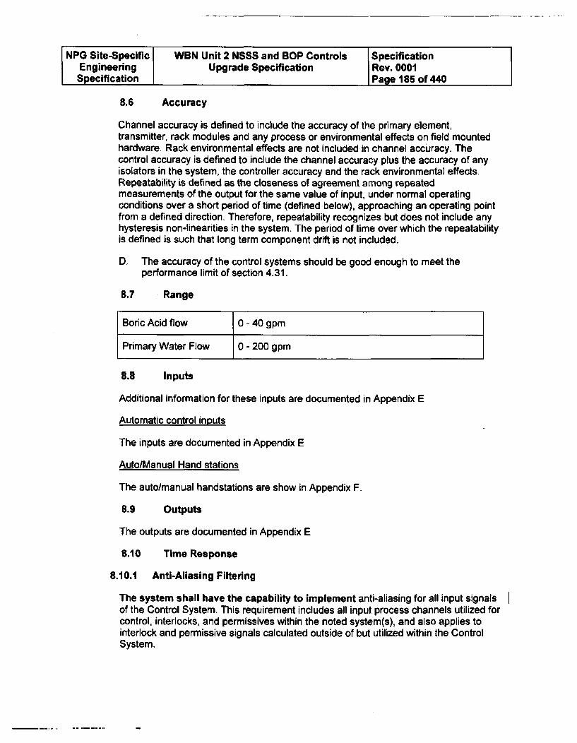
NPG Site-Specific WBN Unit 2 NSSS and BOP Controls SpecificationEngineering Upgrade Specification Rev. 0001Specification Page 185 of 440
8.6 Accuracy
Channel accuracy is defined to include the accuracy of the primary element,transmitter, rack modules and any process or environmental effects on field mountedhardware. Rack environmental effects are not included in channel accuracy. Thecontrol accuracy is defined to include the channel accuracy plus the accuracy of anyisolators in the system, the controller accuracy and the rack environmental effects.Repeatability is defined as the closeness of agreement among repeatedmeasurements of the output for the same value of input, under normal operatingconditions over a short period of time (defined below), approaching an operating pointfrom a defined direction. Therefore, repeatability recognizes but does not include anyhysteresis non-linearities in the system. The period of time over which the repeatabilityis defined is such that long term component drift is not included.
D. The accuracy of the control systems should be good enough to meet theperformance limit of section 4.31.
8.7 Range
8.8 Inputs
Additional information for these inputs are documented in Appendix E
Automatic control inputs
The inputs are documented in Appendix E
Auto/Manual Hand stations
The auto/manual handstations are show in Appendix F.
8.9 Outputs
The outputs are documented in Appendix E
8.10 Time Response
8.10.1 Anti-Aliasing Filtering
The system shall have the capability to implement anti-aliasing for all input signalsof the Control System. This requirement includes all input process channels utilized forcontrol, interlocks, and permissives within the noted system(s), and also applies tointerlock and permissive signals calculated outside of but utilized within the ControlSystem.
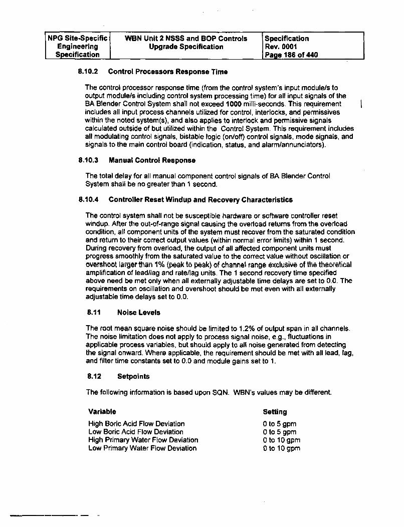
NPG Site-Specific WBN Unit 2 NSSS and BOP Controls SpecificationEngineering Upgrade Specification Rev. 0001Specification Page 186 of 440
8.10.2 Control Processors Response Time
The control processor response time (from the control system's input module/s tooutput module/s including control system processing time) for all input signals of theBA Blender Control System shall not exceed 1000 milli-seconds. This requirementincludes all input process channels utilized for control, interlocks, and permissiveswithin the noted system(s), and also applies to interlock and permissive signalscalculated outside of but utilized within the Control System. This requirement includesall modulating control signals, bistable logic (on/off) control signals, mode signals, andsignals to the main control board (indication, status, and alarm/annunciators).
8.10.3 Manual Control Response
The total delay for all manual component control signals of BA Blender ControlSystem shaBl be no greater than 1 second.
8.10.4 Controller Reset Windup and Recovery Characteristics
The control system shall not be susceptible hardware or software controller resetwindup. After the out-of-range signal causing the overload returns from the overloadcondition, all component units of the system must recover from the saturated conditionand return to their correct output values (within normal error limits) within I second.During recovery from overload, the output of all affected component units mustprogress smoothly from the saturated value to the correct value without oscillation orovershoot larger than 1% (peak to peak) of channel range exclusive of the theoreticalamplification of lead/lag and rate/lag units, The 1 second recovery time specifiedabove need be met only when all externally adjustable time delays are set to 0.0. Therequirements on oscillation and overshoot should be met even with all externallyadjustable time delays set to 0.0.
8.11 Noise Levels
The root mean square noise should be limited to 1.2% of output span in all channels.The noise limitation does not apply to process signal noise, e.g., fluctuations inapplicable process variables, but should apply to all noise generated from detectingthe signal onward. Where applicable, the requirement should be met with all lead, lag,and filter time constants set to 0.0 and module gains set to 1.
8.12 Setpoints
The following information is based upon SON. WBN's values may be different.
Variable Setting
High Boric Acid Flow Deviation 0 to 5 gpmLow Boric Acid Flow Deviation 0 to 5 gpmHigh Primary Water Flow Deviation 0 to 10 gpmLow Primary Water Flow Deviation 0 to 10 gpm
NPG Site-Specific WBN Unit 2 NSSS and BOP Controls SpecificationEngineering Upgrade Specification Rev. 0001Specification Page 187 of 440
8.12 Setpoints (continued)
All settings with the exception of time constants shall be continuously adjustable withintheir range and all time constants shall be continuously adjustable or adjustable inincrements such that any setpoint can be obtained within ± 10% of the setpoint value.
8.13 Requirements for Test and Calibration
The BA Blender Control System is not a protection system, and therefore, does notrequire the capability of being tested at power.
9.0 CVCS CONTROL SYSTEM REQUIREMENTS
9.1 System Description
The chemical and volume control system is a major auxiliary system that functions tocontrol Reactor Coolant System (RCS) inventory, to maintain RCS chemistry, toprovide the reactor coolant pumps with seal water, and to control the soluble poisonconcentration of the RCS. In addition, the CVCS supplies borated coolant to the RCSin the event of an accident.
Major system interfaces include the pressurizer level control system, which variescharging flow based upon pressurizer level; the reactor makeup system that allowsboric acid, demineralized water, and corrosion inhibiting chemicals to be added; andthe emergency core cooling systems, which provide the high pressure injection portionof the system with borated water.
A. Purposes.
1. Maintains programmed pressurizer level.2. Controls reactor coolant chemistry and activity.3. Adjusts and controls reactor coolant boron concentration.4. Provides reactor coolant makeup.5. Supplies seal water to the reactor coolant pumps.6. Portions used for emergency core cooling and emergency boration.7. Used to fill and hydrostatically test the reactor coolant system.
B. Subsystems
1. Charging, letdown, and seal water system subsystems2. Chemical control, purification, and makeup system
9.2 CVCS Control Systems
The chemical and volume controls perform the following functions:
9.2.1 Pressure Control Systems
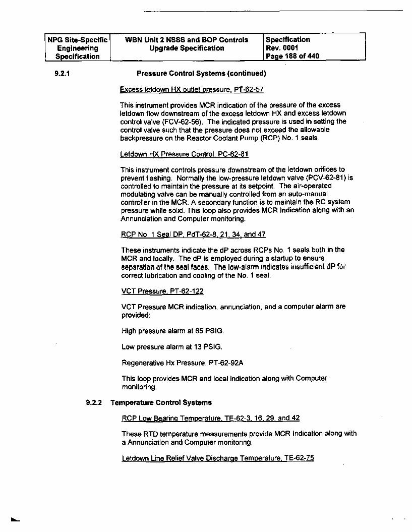
NPG Site-Specific WBN Unit 2 NSSS and BOP Controls SpecificationEngineering Upgrade Specification Rev. 0001Specification Page 188 of 440
9.2.1 Pressure Control Systems (continued)
Excess letdown HX outlet pressure, PT-62-57
This instrument provides MCR indication of the pressure of the excessletdown flow downstream of the excess letdown HX and excess letdowncontrol valve (FCV-62-56). The indicated pressure is used in setting thecontrol valve such that the pressure does not exceed the allowablebackpressure on the Reactor Coolant Pump (RCP) No. 1 seals.
Letdown HX Pressure Control, PC-62-81
This instrument controls pressure downstream of the letdown orifices toprevent flashing. Normally the low-pressure letdown valve (PCV-62-81) iscontrolled to maintain the pressure at its setpoint. The air-operatedmodulating valve can be manually controlled from an auto-manualcontroller in the MCR. A secondary function is to maintain the RO systempressure while solid. This loop also provides MCR Indication along with anAnnunciation and Computer monitoring.
RCP No. 1 Seal DP, PdT-62-8, 21. 34, and 47
These instruments indicate the dP across RCPs No. 1 seals both in theMCR and locally. The dP is employed during a startup to ensureseparation of the seal faces. The low-alarm indicates insufficient dP forcorrect lubrication and cooling of the No. 1 seal.
VCT Pressure, PT-62-122
VCT Pressure MCR indication, annunciation, and a computer alarm areprovided:
High pressure alarm at 65 PSIG.
Low pressure alarm at 13 PSIG.
Regenerative Hx Pressure, PT-62-92A
This loop provides MCR and local indication along with Computermonitoring.
9.2.2 Temperature Control Systems
RCP Low Bearinq Temperature, TE-62-3, 16, 29, and 42
These RTD temperature measurements provide MCR Indication along witha Annunciation and Computer monitoring.
Letdown Line Relief Valve Discharge Temperature. TE-62-75
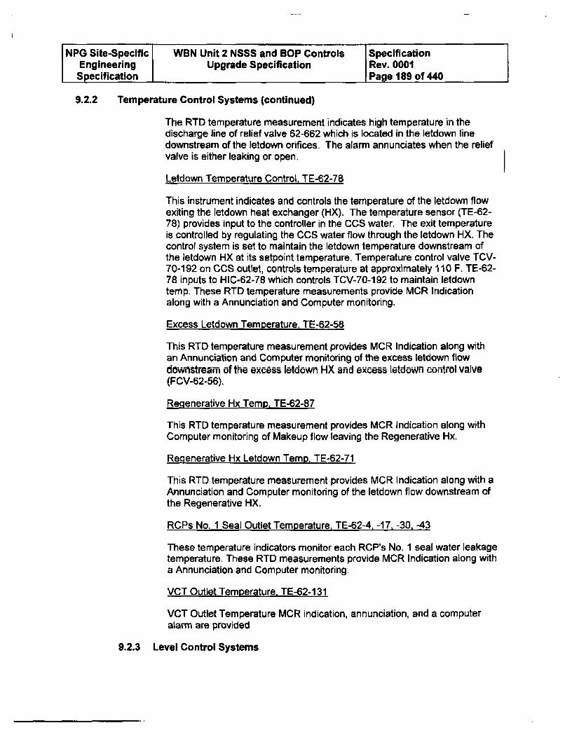
NPG Site-Specific WBN Unit 2 NSSS and BOP Controls SpecificationEngineering Upgrade Specification Rev. 0001Specification Page 189 of 440
9.2.2 Temperature Control Systems (continued)
The RTD temperature measurement indicates high temperature in thedischarge line of relief valve 62-662 which is located in the letdown linedownstream of the letdown orifices. The alarm annunciates when the reliefvalve is either leaking or open.
Letdown Temperature Control, TE-62-78
This instrument indicates and controls the temperature of the letdown flowexiting the letdown heat exchanger (HX). The temperature sensor (TE-62-78) provides input to the controller in the CCS water. The exit temperatureis controlled by regulating the CCS water flow through the letdown HX. Thecontrol system is set to maintain the letdown temperature downstream ofthe letdown HX at its setpoint temperature. Temperature control valve TCV-70-192 on CCS outlet, controls temperature at approximately 110 F. TE-62-78 inputs to HIC-62-78 which controls TCV-70-192 to maintain letdowntemp. These RTD temperature measurements provide MCR Indicationalong with a Annunciation and Computer monitoring.
Excess Letdown Temperature, TE-62-58
This RTD temperature measurement provides MCR Indication along withan Annunciation and Computer monitoring of the excess letdown flowdownstream of the excess letdown HX and excess letdown control valve(FCV-62-56).
Regenerative Hx TemD. TE-62-87
This RTD temperature measurement provides MCR Indication along withComputer monitoring of Makeup flow leaving the Regenerative Hx.
Regenerative Hx Letdown Temp, TE-62-71
This RTD temperature measurement provides MCR Indication along with aAnnunciation and Computer monitoring of the letdown flow downstream ofthe Regenerative HX.
RCPs No. 1 Seal Outlet Temperature, TE-62-4. -17, -30. -43
These temperature indicators monitor each RCP's No. 1 seal water leakagetemperature. These RTD measurements provide MCR Indication along witha Annunciation and Computer monitoring.
VCT Outlet Temperature. TE-62-131
VCT Outlet Temperature MCR indication, annunciation, and a computeralarm are provided
9.2.3 Level Control Systems
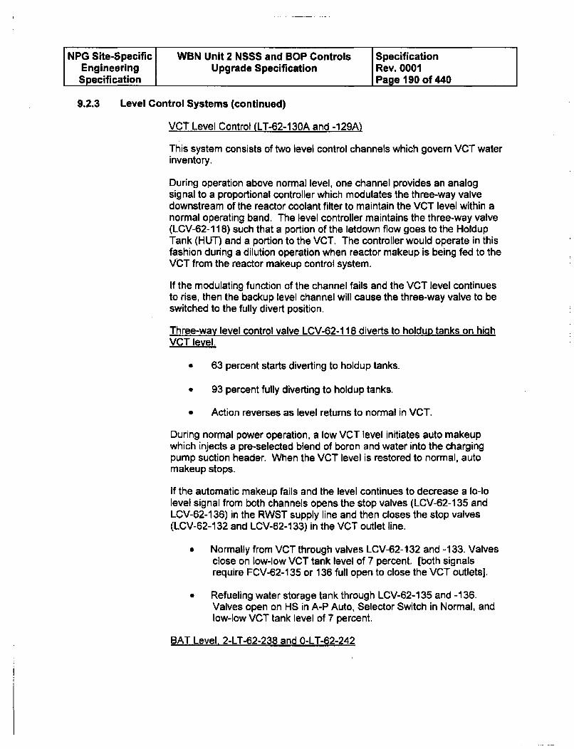
NPG Site-Specific WBN Unit 2 NSSS and BOP Controls SpecificationEngineering Upgrade Specification Rev. 0001Specification Page 190 of 440
9.2.3 Level Control Systems (continued)
VCT Level Control (LT-62-130A and -129A)
This system consists of two level control channels which govern VCT waterinventory.
During operation above normal level, one channel provides an analogsignal to a proportional controller which modulates the three-way valvedownstream of the reactor coolant filter to maintain the VCT level within anormal operating band. The level controller maintains the three-way valve(LCV-62-1 18) such that a portion of the letdown flow goes to the HoldupTank (HUT) and a portion to the VCT. The controller would operate in thisfashion during a dilution operation when reactor makeup is being fed to theVCT from the reactor makeup control system.
If the modulating function of the channel fails and the VCT level continuesto rise, then the backup level channel will cause the three-way valve to beswitched to the fully divert position.
Three-way level control valve LCV-62-118 diverts to holdup tanks on highVCT level.
* 63 percent starts diverting to holdup tanks.
* 93 percent fully diverting to holdup tanks.
* Action reverses as level returns to normal in VCT.
During normal power operation, a low VCT level initiates auto makeupwhich injects a pre-selected blend of boron and water into the chargingpump suction header. When the VCT level is restored to normal, automakeup stops.
if the automatic makeup fails and the level continues to decrease a Io-lolevel signal from both channels opens the stop valves (LCV-62-135 andLCV-62-136) in the RWST supply line and then closes the stop valves(LCV-62-132 and LCV-62-133) in the VCT outlet line.
" Normally from VCT through valves LCV-62-132 and -133. Valvesclose on low-low VCT tank level of 7 percent, [both signalsrequire FCV-62-135 or 136 full open to close the VCT outlets],
" Refueling water storage tank through LCV-62-135 and -136.Valves open on HS in A-P Auto, Selector Switch in Normal, andlow-low VCT tank level of 7 percent.
BAT Level, 2-LT-62-238 and O-LT-62-242
NPG Site-Specific WBN Unit 2 NSSS and BOP Controls SpecificationEngineering Upgrade Specification Rev. 0001Specification Page 191 of 440
9.2.3 Level Control Systems (continued)
These systems indicate BAT's level. BA Tank A is for Unit 1 and is not inthe scope of this upgrade. BA Tank C is common to Unit 1 and 2 and BATank B is for Unit 2. These level loops provide MCR indication along withalarms. The low alarm is set to indicate the minimum level in the tank toensure sufficient boric acid is available to provide suction head to the boricacid transfer pumps.
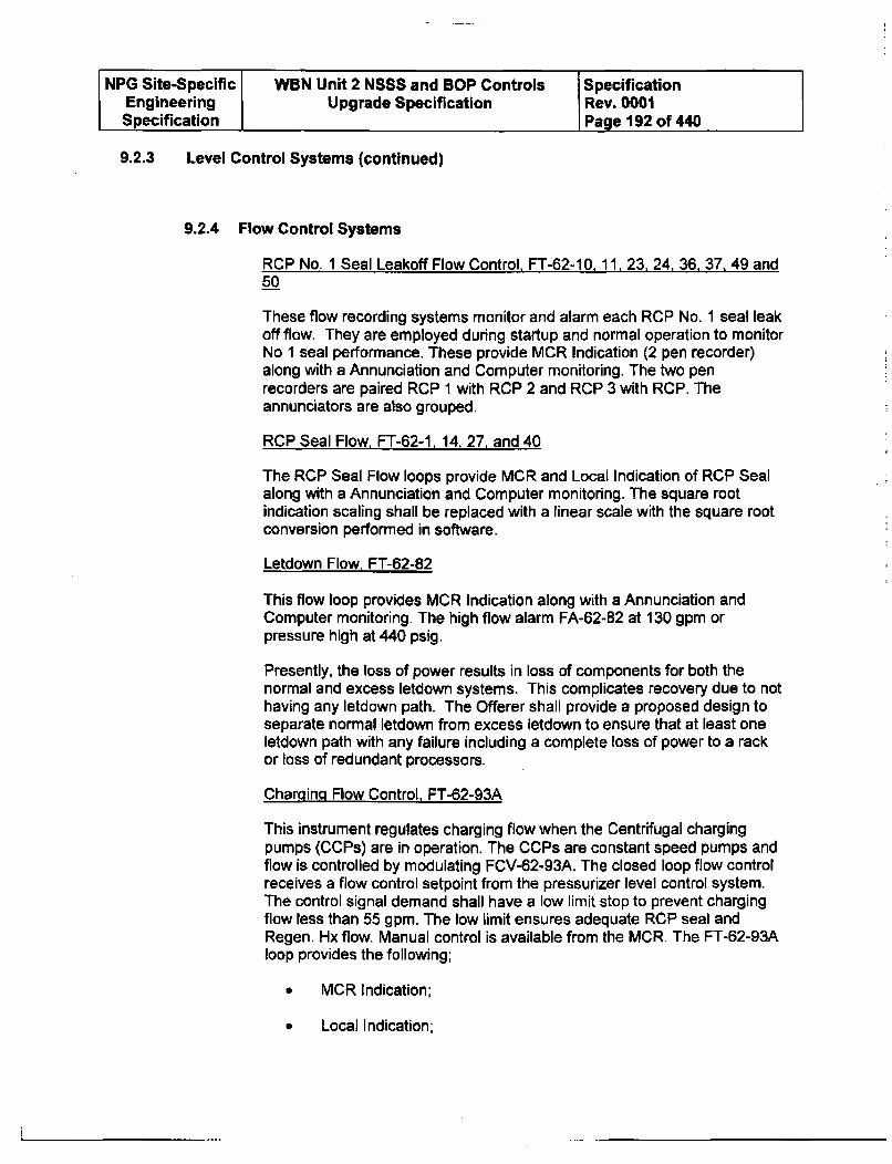
NPG Site-Specific WBN Unit 2 NSSS and BOP Controls SpecificationEngineering Upgrade Specification Rev. 0001Specification Page 192 of 440
9.2.3 Level Control Systems (continued)
9.2.4 Flow Control Systems
RCP No. 1 Seal Leakoff Flow Control, FT-62-10, 11, 23, 24, 36, 37, 49 and50
These flow recording systems monitor and alarm each RCP No. 1 seal leakoff flow. They are employed during startup and normal operation to monitorNo 1 seal performance. These provide MCR Indication (2 pen recorder)along with a Annunciation and Computer monitoring. The two penrecorders are paired RCP 1 with RCP 2 and RCP 3 with RCP. Theannunciators are also grouped.
RCP Seal Flow, FT-62-1, 14, 27, and 40
The RCP Seal Flow loops provide MCR and Local Indication of RCP Sealalong with a Annunciation and Computer monitoring. The square rootindication scaling shall be replaced with a linear scale with the square rootconversion performed in software.
Letdown Flow, FT-62-82
This flow loop provides MCR Indication along with a Annunciation andComputer monitoring. The high flow alarm FA-62-82 at 130 gpm orpressure high at 440 psig.
Presently, the loss of power results in loss of components for both thenormal and excess letdown systems. This complicates recovery due to nothaving any letdown path. The Offerer shall provide a proposed design toseparate normal letdown from excess letdown to ensure that at least oneletdown path with any failure including a complete loss of power to a rackor loss of redundant processors.
Charging Flow Control, FT-62-93A
This instrument regulates charging flow when the Centrifugal chargingpumps (CCPs) are in operation. The CCPs are constant speed pumps andflow is controlled by modulating FCV-62-93A. The closed loop flow controlreceives a flow control setpoint from the pressurizer level control system.The control signal demand shall have a low limit stop to prevent chargingflow less than 55 gpm. The low limit ensures adequate RCP seal andRegen. Hx flow. Manual control is available from the MCR. The FT-62-93Aloop provides the following;
0 MCR Indication;
• Local Indication;
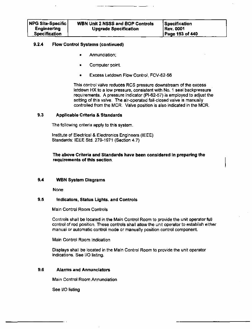
NPG Site-Specific WBN Unit 2 NSSS and BOP Controls SpecificationEngineering Upgrade Specification Rev. 0001Specification Page 193 of 440
9.2.4 Flow Control Systems (continued)
* Annunciation;
* Computer point.
* Excess Letdown Flow Control, FCV-62-56
This control valve reduces RCS pressure downstream of the excessletdown HX to a low pressure, consistent with No. 1 seal backpressurerequirements. A pressure indicator (PI-62-57) is employed to adjust thesetting of this valve. The air-operated fail-closed valve is manuallycontrolled from the MCR. Valve position is also indicated in the MCR.
9.3 Applicable Criteria & Standards
The following criteria apply to this system.
Institute of Electrical & Electronics Engineers (IEEE)Standards: IEEE Std. 279-1971 (Section 4.7)
The above Criteria and Standards have been considered in preparing therequirements of this section.
9.4 WBN System Diagrams
None
9.5 Indicators, Status Lights. and Controls
Main Control Room Controls
Controls shall be located in the Main Control Room to provide the unit operator fullcontrol of rod position. These controls shall allow the unit operator to establish eithermanual or automatic control mode or manually position control component.
Main Control Room Indication
Displays shall be located in the Main Control Room to provide the unit operatorindications. See I/O listing.
Alarms and Annunciators
Main Control Room Annunciation
9.6
See I/0 listing
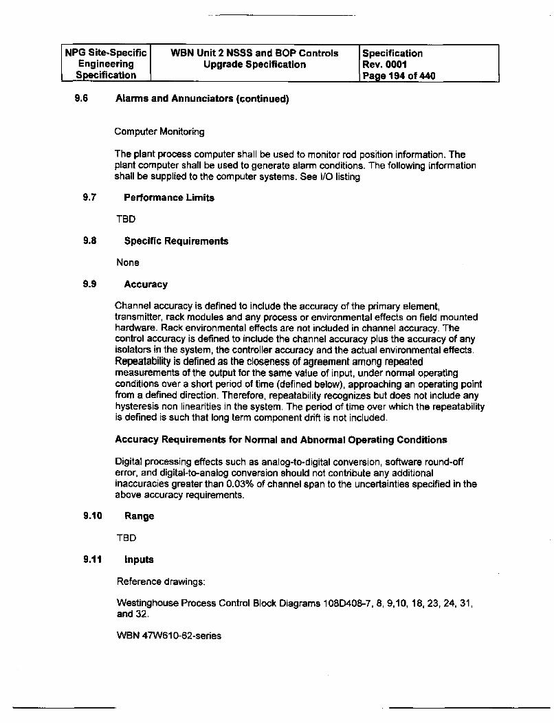
NPG Site-Specific WBN Unit 2 NSSS and BOP Controls SpecificationEngineering Upgrade Specification Rev. 0001Specification Page 194 of 440
9.6 Alarms and Annunciators (continued)
Computer Monitoring
The plant process computer shall be used to monitor rod position information. Theplant computer shall be used to generate alarm conditions. The following informationshall be supplied to the computer systems. See I/O listing
9.7 Performance Limits
TBD
9.8 Specific Requirements
None
9.9 Accuracy
Channel accuracy is defined to include the accuracy of the primary element,transmitter, rack modules and any process or environmental effects on field mountedhardware. Rack environmental effects are not included in channel accuracy. Thecontrol accuracy is defined to include the channel accuracy plus the accuracy of anyisolators in the system, the controller accuracy and the actual environmental effects.Repeatability is defined as the closeness of agreement among repeatedmeasurements of the output for the same value of input, under normal operatingconditions over a short period of time (defined below), approaching an operating pointfrom a defined direction. Therefore, repeatability recognizes but does not include anyhysteresis non linearities in the system. The period of time over which the repeatabilityis defined is such that long term component drift is not included.
Accuracy Requirements for Normal and Abnormal Operating Conditions
Digital processing effects such as analog-to-digital conversion, software round-offerror, and digital-to-analog conversion should not contribute any additionalinaccuracies greater than 0.03% of channel span to the uncertainties specified in theabove accuracy requirements.
9.10 Range
TBD
9.11 Inputs
Reference drawings:
Westinghouse Process Control Block Diagrams 108D408-7, 8, 9,10, 18, 23, 24, 31,and 32.
WBN 47W610-62-series
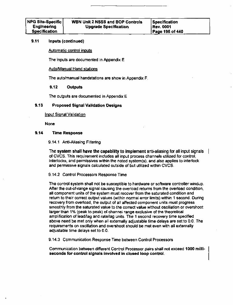
NPG Site-Specific WBN Unit 2 NSSS and BOP Controls SpecificationEngineering Upgrade Specification Rev. 0001Specification Page 195 of 440
9.11 Inputs (continued)
Automatic control inputs
The inputs are documented in Appendix E
Auto/Manual Hand stations
The auto/manual handstations are show in Appendix F.
9.12 Outputs
The outputs are documented in Appendix E
9.13 Proposed Signal Validation Designs
Input Signal Validation
None
9.14 Time Response
9.14.1 Anti-Aliasing Filtering
The system shall have the capability to implement anti-aliasing for all input signalsof CVCS. This requirement includes all input process channels utilized for control,interlocks, and permissives within the noted system(s), and also applies to interlockand permissive signals calculated outside of but utilized within CVCS.
9.14.2 Control Processors Response Time
The control system shall not be susceptible to hardware or software controller windup.After the out-of-range signal causing the overload returns from the overload condition,all component units of the system must recover from the saturated condition andreturn to their correct output values (within normal error limits) within 1 second. Duringrecovery from overload, the output of all affected component units must progresssmoothly from the saturated value to the correct value without oscillation or overshootlarger than 1% (peak to peak) of channel range exclusive of the theoreticalamplification of lead/lag and rate/lag units. The 1 second recovery time specifiedabove need be met only when all externally adjustable time delays are set to 0.0. Therequirements on oscillation and overshoot should be met even with all externallyadjustable time delays set to 0.0.
9.14.3 Communication Response Time between Control Processors
Communication between different Control Processor pairs shall not exceed 1000 milli-seconds for control signals involved in closed loop control.

NPG Site-Specific WBN Unit 2 NSSS and BOP Controls SpecificationEngineering Upgrade Specification Rev. 0001Specification Page 196 of 440
9.14.4 Manual Control Response
The total delay for all manual component control signals of CVCS shall be no greaterthan 1000 milli-seconds.
9.15 Controller Reset Windup and Recovery Characteristics
The control system shall not be susceptible hardware or software controller resetwindup. After the out-of-range signal causing the overload returns from the overloadcondition, all component units of the system must recover from the saturated conditionand return to their correct output values (within normal error limits) within 1 second.During recovery from overload, the output of all affected component units mustprogress smoothly from the saturated value to the correct value without oscillation orovershoot larger than 1% (peak to peak) of channel range exclusive of the theoreticalamplification of lead/lag and rate/lag units. The I second recovery time specifiedabove need be met only when all externally adjustable time delays are set to 0.0. Therequirements on oscillation and overshoot should be met even with all externallyadjustable time delays set to 0.0.
9.16 Noise Levels
The root mean square noise should be limited to 1.2% of output span in all channels.The noise limitation does not apply to process signal noise, e.g., fluctuations inapplicable process variables, but should apply to all noise generated from detectingthe signal ohward. Where applicable, the requirement should be met with all lead, lag,and filter time constants set to 0.0 and module gains set to 1.
9.17 Programmed Functions
None
9.18 Setpoints
All settings with the exception of time constants shall be continuously adjustable withintheir range and all time constants shall be continuously adjustable or adjustable inincrements such that any setpoint can be obtained within ± 10% of the setpoint value.The following setpoint information is not WBN Unit 2 specific. WBN Unit 2 values mustbe obtained from the WBN Unit 2 PLS document.
WBN Unit I (post SGR) PLS
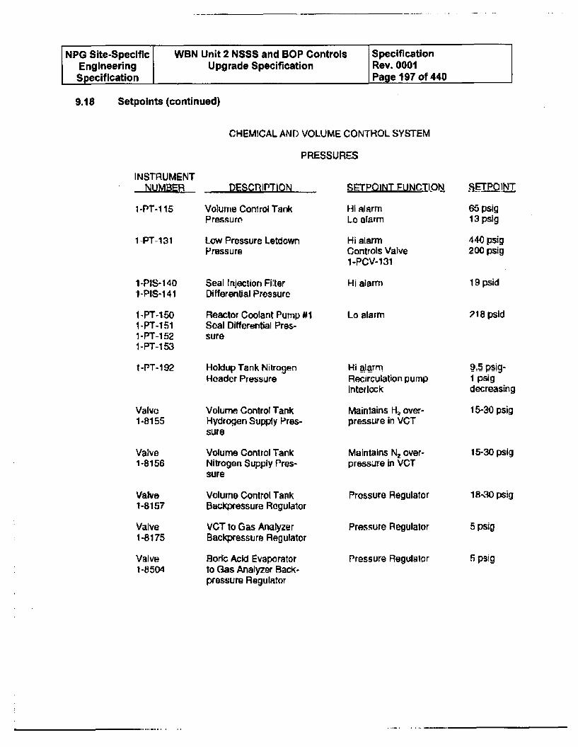
NPG Site-Specific WBN Unit 2 NSSS and BOP Controls SpecificationEngineering Upgrade Specification Rev. 0001Specification Page 197 of 440
9.18 Setpoints (continued)
CHEMICAL AND VOLUME CONTROL SYSTEM
PRESSURES
INSTRUMENT
1-PT-1 15
1-_PT-1 31
1 -PIS- 1401-PIS-141
1-PT-1501-PT-1511 -PT-1 521-PT-153
1-PT-192
DESCRIPTION
Volume Conirol TankPressure
Low Pressure LetdownPressure
Seal Injection FilterDifferential Pressure
Reactor Coolant Pump #1Seal Differential Pres-sure
Holdup Tank NitrogenHeader Pressure
Volume Control TankHydrogen Supply Pres-sure
Volume Control TankNitrogen Supply Pres-sure
Volume Control TankBackpressure Rogulalor
VCT to Gas AnalyzerBackpressure Regulator
Boric Acid 2vaporatorto Gas Analyzer Back-pressure Regulator
SETPOINT FUNCTION
HI alarmLo alarm
SETPOINT
Hi alarmControls Valve1-PCV-131
Hi alarm
Lo alarm
Hi alarmRecirculation pumpInterlock
Maintains H. over-pressure in VOT
Maintains N. over-pressure in VCT
Prossure Regulator
Pressure Regulator
Pressure Regulator
65 psig13 psig
440 psig200 psig
19 psid
218 psld
Valve1-8155
Valve1-8156
Valve1-8157
Valve1-8175
ValveI-8504
9.5 pslig-I psigdecreasing
15-30 psig
15-30 psig
18-30 psig
5 psig
5 psig
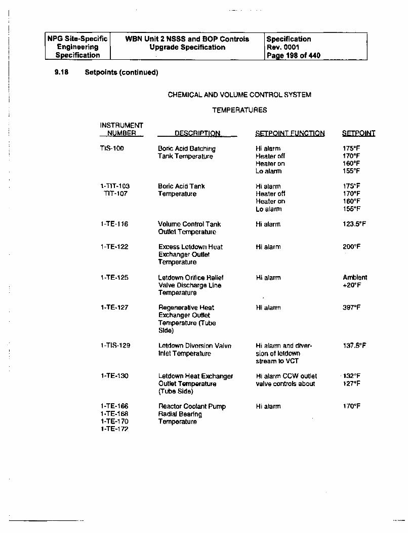
NPG Site-Specific WBN Unit 2 NSSS and BOP Controls SpecificationEngineering Upgrade Specification Rev. 0001Specification Page 198 of 440
9.18 Setpoints (continued)
CHEMICAL AND VOLUME CONTROL SYS;TEM
TEMPERATURES
INSTRUMENTNUMBER DESCRIPTION SETPOINT FUNCTION SEIPQJIN
TIS-100
1-TIT-103T1T-107
1-TE-1 16
1-TE-122
1 -TE-1 25
1-TE-127
Boric Acid BaichirigTank Temperature
Boric Acid TankTemperature
Volume Control TankOutlet Temperature
Excess Letdown HeatExchanger OutletTemperature
Letdown Orifice ReliefValve Discharge LineTemperature
Regenerative HeatExchanger OutletTemperature (TubeSide)
Letdown Diversion ValveInlet Temperature
Letdown Heat ExchangerOutlet Temperature(Tube Side)
Reactor Coolant PumpRadial BearingTemperature
Hi alarmHeater offHeater onLo alarm
Hi alarmHeater offHeater onLo alarm
Hi alarm
Hi alarm
175°FI 70*F160*F1550F
175"F170°F1600F1550 F
123.5F
200WF
Hi alarm
Hi alarm
A2tient+200 F
397OF
I -TIS-129
1 -TE-130
1 -TE- 1661-TE-1681-TE-1701 -TE-1 7?
Hi alarm and diver-sion ot letdownstream to VCT
Hi alarm CCW outletvalve controls about
Hi alarm
137.50F:
132"F1279F
170tp
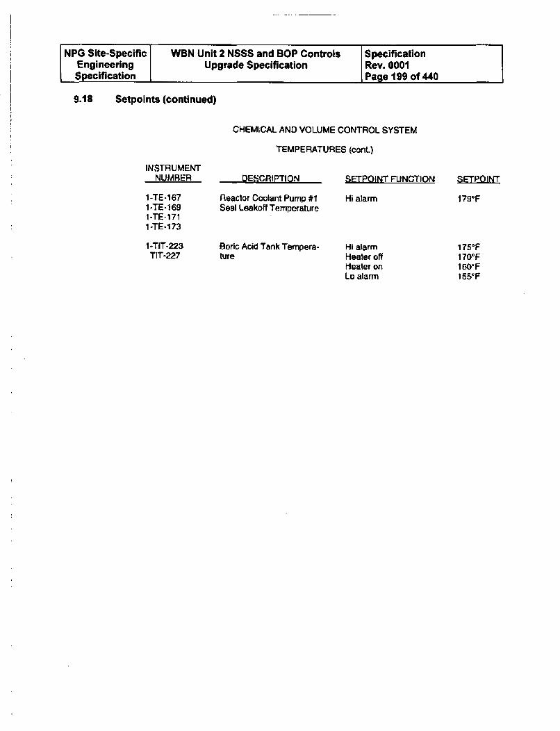
NPG Site-Specific WBN Unit 2 NSSS and BOP Controls I SpecificationEngineering Upgrade Specification I Rev. 0001Specification Page 199 of 440
9.18 Setpoints (continued)
CHEMICAL AND VOLUME CONTROL SYSTEM
TEMPERATURES (cont)
INSTRUMENTNUMBER
I-TE-1671-TE-1691-TE-1711-TE-173
I-TIT-223TIT-227
DESCRIPTION
Reactor Coolant Pump #1Seal Leakoff Temporature
Boric Acid Tank Tempera-ture
SETPOINT FUNCTION SETPOINT
Hi alarm 179oF
Hi alarmHeater offHeater onLo alarm
175'F170OF160'Fj55ep
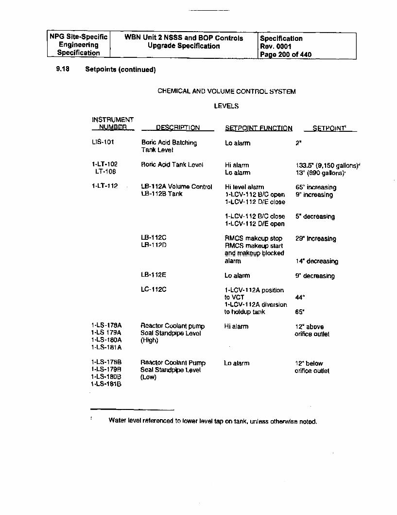
NPG Site-Specific WBN Unit 2 NSSS and BOP Controls SpecificationEngineering Upgrade Specification Rev. 0001Specification Page 200 of 440
9.18 Setpoints (continued)
CHEMICAL AND VOLUME CONTROL SYSTEM
LEVELS
INSTRUMENT
LIS-I01
DESCRIPTI ON
Boric Acid BatchingTank Level
Boric Acid Tank Leovel
LB-1 12A Volume ControlLB-1 12B Tank
§EEQIT~g[EUNCTION SETPOINV
Lo alarm
Hi alarmLo alarm
2"
1-LT-102LT-106
1-LT-1 12
133.5* (9,150 gallons)-13" (890 gallons)-
LB-112CLB-i 1?D
LB-1 12E
LC-1 12C
Hi level alarm1 -LCV-1 12 8/C open1-LCV-112 DIE close
I-LCV-1 2 B/C close1-LCV-112 D/E open
RMCS makeup stopRMCS makeup slartand makeup blockedalarm
Lo alarm
I -LCV- 112A positionto VCT1-LCV- 1 12A diversionto holdup tank
65" increasing95 increasing
5" decreasing
29" increasing
14" decreasing
9" decreasing
44"
65'
126 aboveorifice outlet
12* beloworifice outlet
1-LS-178A1-LS 179A1 -LS-1B0A1 -LS-181A
1-LS-178B1 -LS- 17981-LS-180BI -LS-1 81B
Reactor Coolant pumpSoal Standpipe Levol(High)
Reactor Coolant PumpSeal Standpipe Level(Low)
Hi alarm
Lo alarm
Water level referenced to lower level lap on tank, unless otherwise noted.
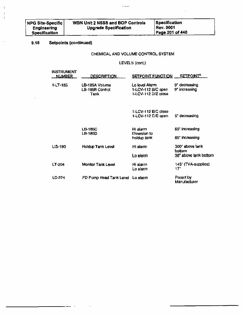
NPG Site-Specific WBN Unit 2 NSSS and BOP Controls SpecificationEngineering Upgrade Specification Rev. 0001Specification Page 201 of 440
9.18 Setpoints (continued)
CHEMICAL AND VOLUME CONTROL SYSTEM
LEVELS (cont.)
INSTRUMENTDESCRIPTION SETPOINT FUNCTION __SEQINT.
1 -LT-1B5 LB-1 85A VolumeLB-1 85 Control
Tank
Lo level Alarm1-LCV-112 B/C open1-L.CV-I 12 D/E close
1-LCV- 112 B6C close1-LCV- 112 D/E open
Hi alarmDiversion toholdup tank
9' decreasing94 increasing
LB-185CLB-185D
5* decreasing
65" increasing
65" increasing
300" above tankbottom36" above tlik bottom
145' (TVA-supplied)17"
LIS-190 Holdup Tank Level
Monitor Tank Level
Hi alarm
Lo alarm
Hi alarmLo alarm
LT-204
LC-224 PD Pump Head Tank Level Lo alarm Preset byManufacturer
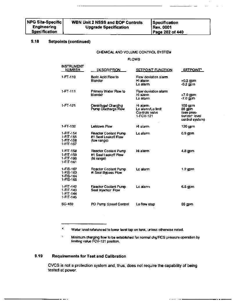
NPG Site-Specific WBN Unit 2 NSSS and BOP Controls SpecificationEngineering Upgrade Specification Rev. 0001Specification Page 202 of 440
9.18 Setpoints (continued)
CHEMICAL AND VOLUME CONTROL SYSTEM
FLOWS
INSTRUMENTNUMBER
I-FT-1 10
1-FT-111
1-FT-121
1-FT-132
1-FIT-1541-FIT-1551-FIT-1561-rrr-157
1-FIT-1 581-FIT-159I-FIT-1601-FIT-161
1-FIS-1 621-FIS-1631 -FIS-164I-FIS-165
1-FIT-1421 -FIT-1 431 -FIT-1 441-FIT-1 45
SC-459
DESCRIPMTION
Boric Acid Flow toBlender
Primary Water Flow toBlender
Centrifugal ChargingPump Discharge Flow
Letdown Row
Reactor Coolant Pump#1 Seal Leakoff Flow(low rango)
Reactor Coolant Pump#1 Seal I.eakoff Flow(hi range)
Roactor Coolant Pump#1 Seal Bypass Flow
Reactor Coolant Pump
Seal Injection Flow
PD Pump Speed Control
SErPOINT FUNCTION
Flow deviation alarmHI alarmLo alarm
Flow deviation alarmHi alarmLa alarm
Hi alarmLo alarrwLo limitControls valveI-FCV-121
SEETPOINT_
+0.2 gpm-0.2 gprn
+7.0 gpm-7.0 gpm
150 gpm56 gpm(see pres-surizer&- levelcontrol system)
130 gpm
0.9 gpm
HI alarm
Lo alarm
Hi alarm 4.8 gpm
Lo alarm
Lo alarm
1.2 gpm
6.5 gpm
55 gpmLo flow stop
K Water level referenced to lower level tap on tank, unless otherwise noted.
- Minimum charging flow to be established for normal chg.RCS pressure operation bylimiting value FCV-1 21 position.
9.19 Requirements for Test and Calibration
CVCS is not a protection system and, thus, does not require the capability of beingtested at power.
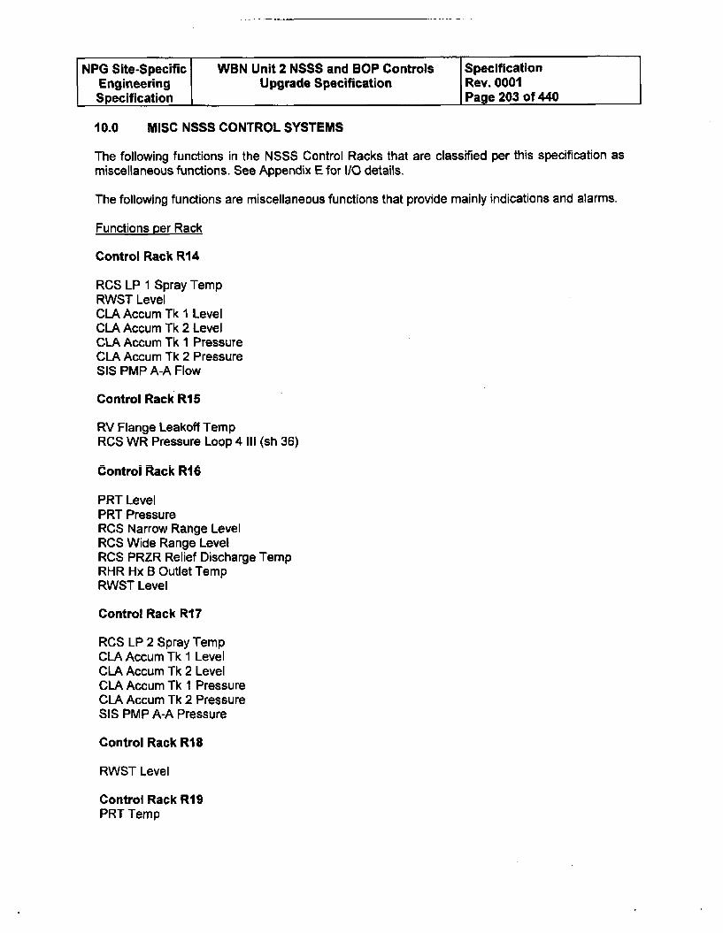
NPG Site-Specific WBN Unit 2 NSSS and BOP Controls SpecificationEngineering Upgrade Specification Rev. 0001Specification I Page 203 of 440
10.0 MISC NSSS CONTROL SYSTEMS
The following functions in the NSSS Control Racks that are classified per this specification asmiscellaneous functions. See Appendix E for I/O details.
The following functions are miscellaneous functions that provide mainly indications and alarms.
Functions per Rack
Control Rack R14
RCS LP 1 Spray TempRWST LevelCLA Accum Tk I LevelCLA Accum Tk 2 LevelCLA Accum Tk 1 PressureCLA Accum Tk 2 PressureSIS PMP A-A Flow
Control Rack R15
RV Flange Leakoff TempRCS WR Pressure Loop 4 III (sh 36)
Control Rack RI6
PRT LevelPRT PressureRCS Narrow Range LevelRCS Wide Range LevelRCS PRZR Relief Discharge TempRHR Hx B Outlet TempRWST Level
Control Rack R17
RCS LP 2 Spray TempCLA Accum Tk 1 LevelCLA Accum Tk 2 LevelCLA Accum Tk I PressureCLA Accum Tk 2 PressureSIS PMP A-A Pressure
Control Rack R18
RWST Level
Control Rack R19PRT Temp
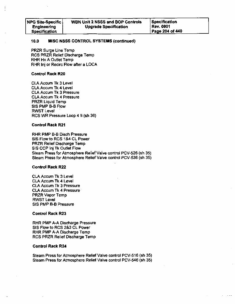
NPG Site-Specific WBN Unit 2 NSSS and BOP Controls SpecificationEngineering Upgrade Specification Rev. 0001Specification Page 204 of 440
10.0 MISC NSSS CONTROL SYSTEMS (continued)
PRZR Surge Line TempRCS PRZR Relief Discharge TempRHR Hx A Outlet TempRHR Inj or Recirc Flow after a LOCA
Control Rack R20
CLA Accum Tk 3 LevelCLA Accum Tk 4 LevelCLA Accum Tk 3 PressureCLA Accum Tk 4 PressurePRZR Liquid TempSIS PMP B-B FlowRWST LevelRCS WR Pressure Loop 4 11 (sh 36)
Control Rack R21
RHR PMP B-B Disch PressureSIS Flow to RCS 1 &4 CL PowerPRZR Relief Discharge TempSS CCP Inj Tk Outlet FlowSteam Press for Atmosphere Relief Valve control PCV-526 (sh 35)Steam Press for Atmosphere Relief Valve control PCV-536 (sh 35)
Control Rack R22
CLA Accum Tk 3 LevelCLA Accum Tk 4 LevelCLA Accum Tk 3 PressureCLA Accum Tk 4 PressurePRZR Vapor TempRWST LevelSIS PMP B-B Pressure
Control Rack R23
RHR PMP A-A Discharge PressureSIS Flow to RCS 2&3 CL PowerRHR PMP A-A Discharge TempRCS PRZR Relief Discharge Temp
Control Rack R24
Steam Press for Atmosphere Relief Valve control PCV-51 6 (sh 35)Steam Press for Atmosphere Relief Valve control PCV-546 (sh 35)
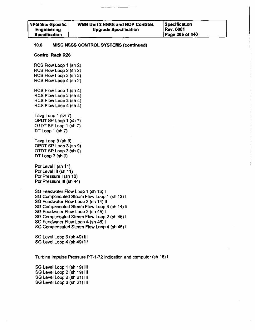
NPG Site-Specific WBN Unit 2 NSSS and BOP Controls SpecificationEngineering Upgrade Specification Rev. 0001Specification Page 205 of 440
10.0 MISC NSSS CONTROL SYSTEMS (continued)
Control Rack R26
RCS Flow Loop 1 (sh 2)RCS Flow Loop 2 (sh 2)RCS Flow Loop 3 (sh 2)RCS Flow Loop 4 (sh 2)
RCS Flow Loop 1 (sh 4)RCS Flow Loop 2 (sh 4)RCS Flow Loop 3 (sh 4)RCS Flow Loop 4 (sh 4)
Tavg Loop 1 (sh 7)OPDT SP Loop 1 (sh 7)OTDT SP Loop 1 (sh 7)DT Loop 1 (sh 7)
Tavg Loop 3 (sh 9)OPDT SP Loop 3 (sh 9)OTDT SP Loop 3 (sh 9)DT Loop 3 (sh 9)
Pzr Level i (sh 11)Pzr Level III (sh 11)Pzr Pressure I (sh 12)Pzr Pressure III (sh 44)
SG Feedwater Flow Loop 1 (sh 13) 1SG Compensated Steam Flow Loop i (sh 13) 1SG Feedwater Flow Loop 3 (sh 14) 11SG Compensated Steam Flow Loop 3 (sh 14) 11SG Feedwater Flow Loop 2 (sh 45) ISG Compensated Steam Flow Loop 2 (sh 45) ISG Feedwater Flow Loop 4 (sh 46) ISG Compensated Steam Flow Loop 4 (sh 46) I
SG Level Loop 3 (sh 49) 111SG Level Loop 4 (sh 49) 111
Turbine Impulse Pressure PT-1-72 Indication and computer (sh 18) 1
SG Level Loop I (sh 19)111SG Level Loop 2 (sh 19) 111SG Level Loop 2 (sh 21) 111SG Level Loop 3 (sh 21) 111
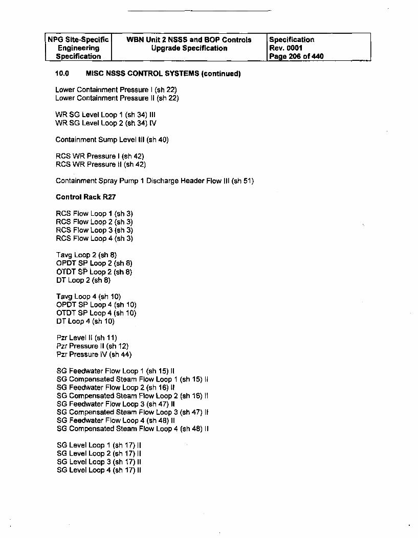
NPG Site-Specific WBN Unit 2 NSSS and BOP Controls SpecificationEngineering Upgrade Specification Rev. 0001Specification Page 206 of 440
10.0 MISC NSSS CONTROL SYSTEMS (continued)
Lower Containment Pressure I (sh 22)Lower Containment Pressure II (sh 22)
WR SG Level Loop 1 (sh 34) 111WR SG Level Loop 2 (sh 34) IV
Containment Sump Level III (sh 40)
RCS WR Pressure I (sh 42)RCS WR Pressure II (sh 42)
Containment Spray Pump I Discharge Header Flow Ill (sh 51)
Control Rack R27
RCS Flow Loop 1 (sh 3)RCS Flow Loop 2 (sh 3)RCS Flow Loop 3 (sh 3)RCS Flow Loop 4 (sh 3)
Tavg Loop 2 (sh 8)OPDT SP Loop 2 (sh 8)OTDT SP Loop 2 (sh 8)DT Loop 2 (sh 8)
Tavg Loop 4 (sh 10)OPDT SP Loop 4 (sh 10)OTDT SP Loop 4 (sh 10)DT Loop 4 (sh 10)
Pzr Level II (sh 11)Pzr Pressure II (sh 12)Pzr Pressure IV (sh 44)
SG Feedwater Flow Loop I (sh 15).11SG Compensated Steam Flow Loop 1 (sh 15) 11SG Feedwater Flow Loop 2 (sh 16) 11SG Compensated Steam Flow Loop 2 (sh 16) 11SG Feedwater Flow Loop 3 (sh 47) 11SG Compensated Steam Flow Loop 3 (sh 47) 11SG Feedwater Flow Loop 4 (sh 48) 11SG Compensated Steam Flow Loop 4 (sh 48) 11
SG Level Loop I (sh 17) 11SG Level Loop 2 (sh 17) 11SG Level Loop 3 (sh 17) 11SG Level Loop 4 (sh 17) 11
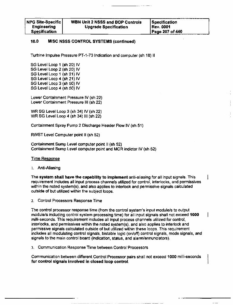
NPG Site-Specific WBN Unit 2 NSSS and BOP Controls SpecificationEngineering Upgrade Specification Rev. 0001Specification Page 207 of 440
10.0 MISC NSSS CONTROL SYSTEMS (continued)
Turbine Impulse Pressure PT-1-73 Indication and computer (sh 18) 11
SO Level Loop 1 (sh 20) IVSO Level Loop 2 (sh 20) IVSG Level Loop 1 (sh 21) IVSO Level Loop 4 (sh 21) IVSO Level Loop 3 (sh 50) IVSO Level Loop 4 (sh 50) IV
Lower Containment Pressure IV (sh 22)Lower Containment Pressure III (sh 22)
WR SG Level Loop 3 (sh 34) IV (sh 22)WR SG Level Loop 4 (sh 34) 111 (sh 22)
Containment Spray Pump 2 Discharge Header Flow IV (sh 51)
RWST Level Computer point Ii (sh 52)
Containment Sump Level computer point II (sh 52)Containment Sump Level computer point and MCR indictor IV (sh 52)
Time Response
i. Anti-Aliasing
The system shall have the capability to implement anti-aliasing for all input signals. Thisrequirement includes all input process channels utilized for control, interlocks, and permissiveswithin the noted system(s), and also applies to interlock and permissive signals calculatedoutside of but utilized within the subject loops.
2. Control Processors Response Time
The control processor response time (from the control system's input module/s to outputmodule/s including control system processing time) for all input signals shall not exceed 1000milli-seconds. This requirement includes all input process channels utilized for control,interlocks, and permissives within the noted system(s), and also applies to interlock andpermissive signals calculated outside of but utilized within these loops. This requirementincludes all modulating control signals, bistable logic (on/off) control signals, mode signals, andsignals to the main control board (indication, status, and alarm/annunciators).
3. Communication Response Time between Control Processors
Communication between different Control Processor pairs shall not exceed 1000 milli-secondsfor control signals Involved in closed loop control.
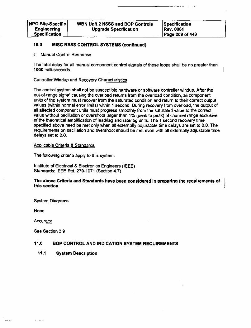
NPG Site-Specific WBN Unit 2 NSSS and SOP Controls SpecificationEngineering Upgrade Specification Rev. 0001Specification Page 208 of 440
10.0 MISC NSSS CONTROL SYSTEMS (continued)
4. Manual Control Response
The total delay for all manual component control signals of these loops shall be no greater than1000 milli-seconds.
Controller Windup and Recovery Characteristics
The control system shall not be susceptible hardware or software controller windup. After theout-of-range signal causing the overload returns from the overload condition, all componentunits of the system must recover from the saturated condition and return to their correct outputvalues (within normal error limits) within 1 second. During recovery from overload, the output ofall affected component units must progress smoothly from the saturated value to the correctvalue without oscillation or overshoot larger than 1 % (peak to peak) of channel range exclusiveof the theoretical amplification of lead/lag and ratellag units. The 1 second recovery timespecified above need be met only when all externally adjustable time delays are set to 0.0. Therequirements on oscillation and overshoot should be met even with all externally adjustable timedelays set to 0.0.
Applicable Criteria & Standards
The following criteria apply to this system.
institute of Electrical & Electronics Engineers (IEEE)Standards: IEEE Std. 279-1971 (Section 4,7)
The above Criteria and Standards have been considered in preparing the requirements ofthis section.
System Diagrams
None
Accuracy
See Section 3.9
11.0 SOP CONTROL AND INDICATION SYSTEM REQUIREMENTS
11.1 System Description
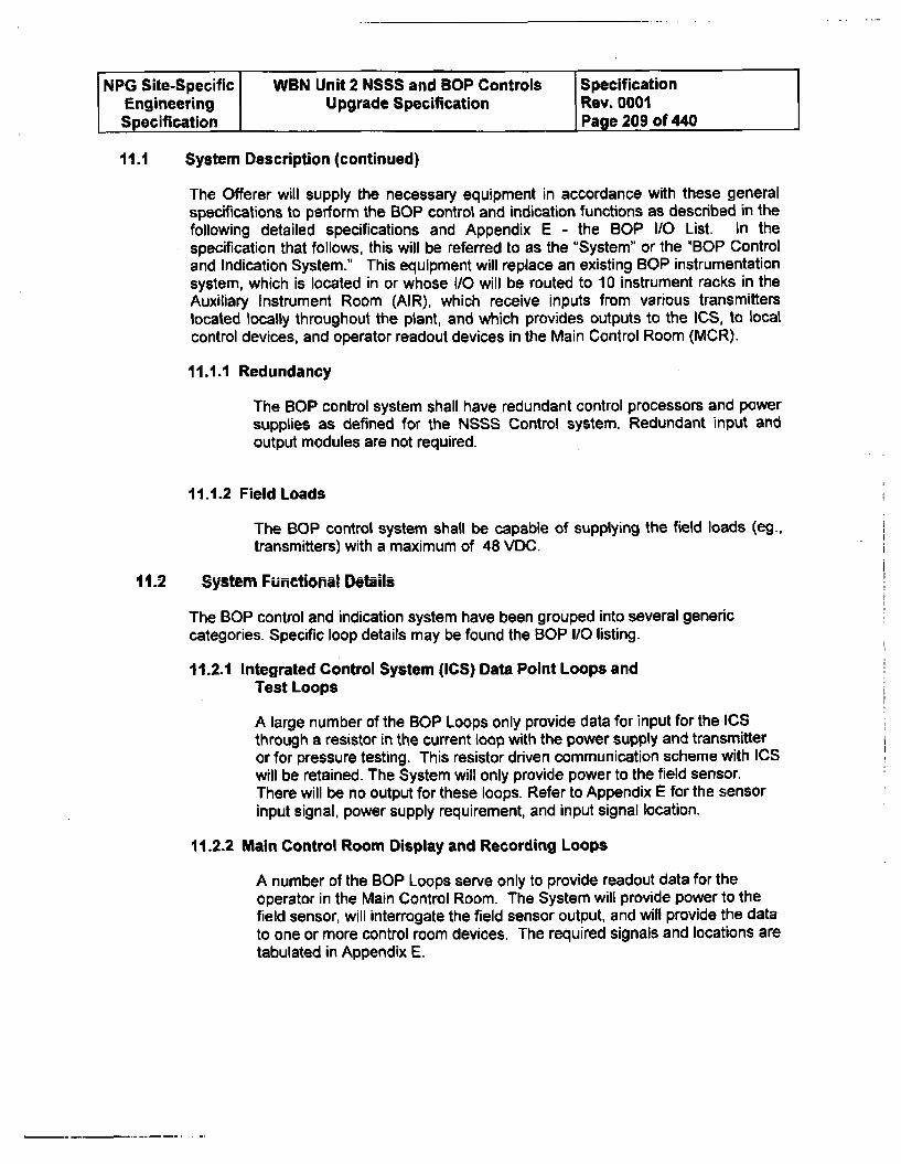
NPG Site-Specific WBN Unit 2 NSSS and SOP Controls SpecificationEngineering Upgrade Specification Rev. 0001Specification Page 209 of 440
11.1 System Description (continued)
The Offerer will supply the necessary equipment in accordance with these generalspecifications to perform the SOP control and indication functions as described in thefollowing detailed specifications and Appendix E - the SOP I/O List. In thespecification that follows, this will be referred to as the "System" or the "BOP Controland Indication System." This equipment will replace an existing SOP instrumentationsystem, which is located in or whose I/O will be routed to 10 instrument racks in theAuxiliary Instrument Room (AIR), which receive inputs from various transmitterslocated locally throughout the plant, and which provides outputs to the ICS, to localcontrol devices, and operator readout devices in the Main Control Room (MCR).
11.1.1 Redundancy
The SOP control system shall have redundant control processors and powersupplies as defined for the NSSS Control system. Redundant input andoutput modules are not required.
11.1.2 Field Loads
The BOP control system shall be capable of supplying the field loads (eg.,transmitters) with a maximum of 48 VOC.
11.2 System Functional Details
The BOP control and indication system have been grouped into several genericcategories. Specific loop details may be found the BOP I/O listing.
11.2.1 Integrated Control System (ICS) Data Point Loops andTest Loops
A large number of the SOP Loops only provide data for input for the ICSthrough a resistor in the current loop with the power supply and transmitteror for pressure testing. This resistor driven communication scheme with ICSwill be retained. The System will only provide power to the field sensor.There will be no output for these loops. Refer to Appendix E for the sensorinput signal, power supply requirement, and input signal location.
11.2.2 Main Control Room Display and Recording Loops
A number of the SOP Loops serve only to provide readout data for theoperator in the Main Control Room. The System will provide power to thefield sensor, will interrogate the field sensor output, and will provide the datato one or more control room devices. The required signals and locations aretabulated in Appendix E.
NPG Site-Specific WBN Unit 2 NSSS and BOP Controls SpecificationEngineering Upgrade Specification Rev. 0001Specification Page 210 of 440
11.2.3 Display and Contact Output Loops
A number of the BOP Loops provide readout data for the operator in theMain Control Room and in addition, provide contact outputs for input toexternally developed logic, annunciation and/or status lights, or possiblycontacts alone. The System will provide power to the field sensor, willinterrogate the field sensor output, will provide the data to one or morecontrol room devices, and will provide contacts that will change status atpredetermined setpoints. The required signals, contact outputs, andlocations are tabulated in Appendix E. All contacts will have externallysupplied interrogation voltage.
11.2.4 Display and Contact Output Loops with field located MVII
A number of the BOP Loops have a locally mounted MV/I converter whichhas its own power supply, takes an input from a thermocouple, and deliversa 4 to 20 mA signal back to the signal processing equipment. The signalprocessing equipment provided by the Offerer will provide readout data forthe operator in the Main Control Room and provide contact outputs for inputto externally developed logic or annunciation and status lights. The Systemwill interrogate the input current signal, will provide the data to one or morecontrol room devices, and will provide contacts that will change status atpredetermined setpoints. The required signals, contact outputs, andlocations are tabulated in Appendix E. All contacts will have externallysupplied interrogation voltage.
11.2.5 Reactor Building Floor and Equipment Drain Sump LevelLoops
The Offerer will supply signal-processing equipment as tabulated inAppendix E to process signals from four ultrasonic Reactor Building Sumplevel sensors and transmitters. The sensors and transmitters are locallymounted and have their own power supplies. The outputs will be indicationand switch outputs for annunciation and externally developed pump logic.The System will interrogate the field sensor output, will provide the data toone or more control room devices, and will provide contact outputs that willchange status at predetermined setpoints.
11.2.6 Containment Moisture Loops
The Offerer will provide signal processing equipment for 2 moisture sensingloops. The system will be required to interrogate a 4 to 20 mA input signalrepresenting 40 to 140 degrees F dewpoint temperature. The System willmonitor rate of change of the input and provide a contact output at apredetermined dewpoint temperature rate of change. See Appendix E forinput output details.
NPG Site-Specific WBN Unit 2 NSSS and BOP Controls SpecificationEngineering Upgrade Specification Rev. 0001Specification PPage 211 of 440
11.2.7 Main Feed Pump Suction Pressure Instrumentation andAlarm
Sensors 2-PT-5-31 and 2-PT-2-129 provide pressure monitoring for 2 BOPpoints and are combined arithmetically to provide an alarm of low netpositive suction pressure for the main feed pumps. Each of the 2 loopshave an indicator on the on the Main Control Boards. Details on the inputpoints and output points for the 2 loops are tabulated in Appendix E. Inaddition, a switch contact output denoted as 2-PS-2-129A will be required todrive an annunciator window based on the arithmetic difference betweenthese 2 loop values. Scaling will be provided later.
11.2.8 Annulus Vacuum Control and Indication Loops
Normal annulus vacuum control is maintained by 2 separate differentialpressure measurement and control loops. Each loop measures differentialpressure between the Annulus and Auxiliary Building exhaust stack. Only 1of the 2 control loops is active at any one time. The controlling loop isswitched out and the standby loop is switched in at a predeterminedsetpoint. The inputs and outputs are tabulated in Appendix E. The controlfunction is simple setpoint control. For information, the configurations of theexisting loops are shown in figures 11.2.8-1 and 11.2.8-2.
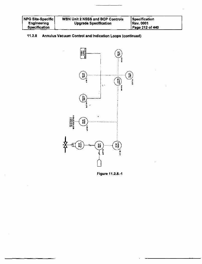
NPG Site-Specific WBN Unit 2 NSSS and SOP Controls SpecificationEngineering Upgrade Specification Rev. 0001Specification Page 212 of 440
11.2.8 Annulus Vacuum Control and Indication Loops (continued)
K --
......... . ... .........
-,-
(ý )--- -- -......
VR
i~ ..........
Figure 11.2.8.-1
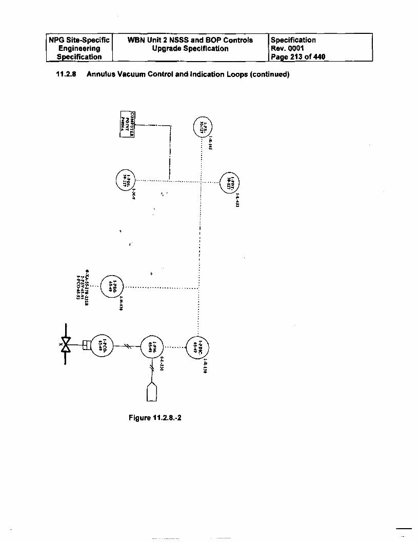
NPG Site-Specific WBN Unit 2 NSSS and BOP Controls SpecificationEngineering Upgrade Specification Rev. 0001Specification I Page 213 of 440
11.2.8 Annulus Vacuum Control and Indication Loops (continued)
•.@•_ .. .............. ............. ............ .
1 f- (1
a
(S~am tt~). .............
4P ................
--"6- b . .. . ... .. .
Figure 11.2.8.-2
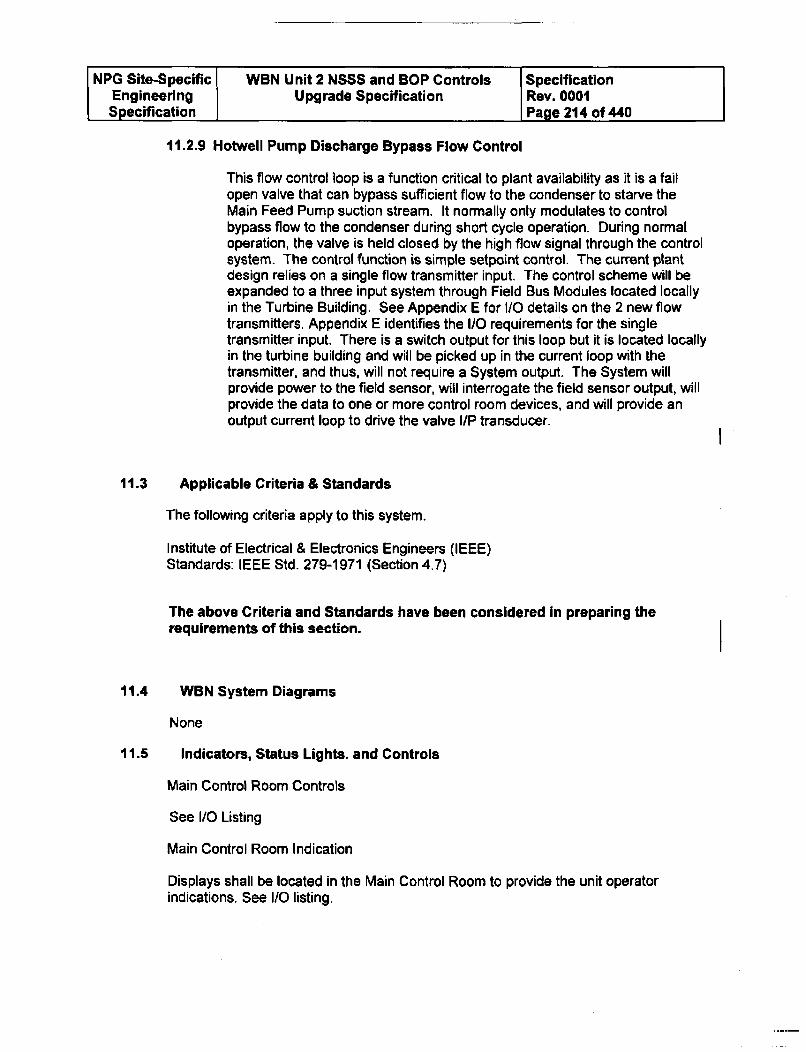
NPG Site-Specific WBN Unit 2 NSSS and BOP Controls SpecificationEngineering Upgrade Specification Rev. 0001Specification Page 214 of 440
11.2.9 Hotwell Pump Discharge Bypass Flow Control
This flow control loop is a function critical to plant availability as it is a failopen valve that can bypass sufficient flow to the condenser to starve theMain Feed Pump suction stream. It normally only modulates to controlbypass flow to the condenser during short cycle operation. During normaloperation, the valve is held closed by the high flow signal through the controlsystem. The control function is simple setpoint control. The current plantdesign relies on a single flow transmitter input. The control scheme will beexpanded to a three input system through Field Bus Modules located locallyin the Turbine Building. See Appendix E for I/O details on the 2 new flowtransmitters. Appendix E identifies the I/O requirements for the singletransmitter input. There is a switch output for this loop but it is located locallyin the turbine building and will be picked up in the current loop with thetransmitter, and thus, will not require a System output. The System willprovide power to the field sensor, will interrogate the field sensor output, willprovide the data to one or more control room devices, and will provide anoutput current loop to drive the valve I/P transducer.
11.3 Applicable Criteria & Standards
The following criteria apply to this system.
Institute of Electrical & Electronics Engineers (IEEE)Standards: IEEE Std. 279-1971 (Section 4.7)
The above Criteria and Standards have been considered in preparing therequirements of this section.
11.4 WBN System Diagrams
None
11.5 Indicators, Status Lights. and Controls
Main Control Room Controls
See I/O Listing
Main Control Room Indication
Displays shall be located in the Main Control Room to provide the unit operatorindications. See I/O listing.
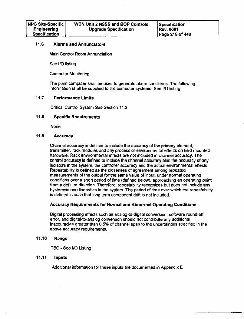
NPG Site-Specific WBN Unit 2 NSSS and BOP Controls SpecificationEngineering Upgrade Specification Rev. 0001Specification Page 215 of 440
11.6 Alarms and Annunciators
Main Control Room Annunciation
See IO listing
Computer Monitoring
The plant computer shall be used to generate alarm conditions. The followinginformation shall be supplied to the computer systems. See I/O listing
11.7 Performance Limits
Critical Control System See Section 11.2.
11.8 Specific Requirements
None
11.9 Accuracy
Channel accuracy is defined to include the accuracy of the primary element,transmitter, rack modules and any process or environmental effects on field mountedhardware. Rack environmental effects are not included in channel accuracy. Thecontrol accuraey is defined to include the channel accuracy plus the accuracy of anyisolators in the system, the controller accuracy and the actual environmental effects.Repeatability is defined as the closeness of agreement among repeatedmeasurements of the output for the same value of input, under normal operatingconditions over a short period of time (defined below), approaching an operating pointfrom a defined direction. Therefore, repeatability recognizes but does not include anyhysteresis non linearities in the system. The period of time over which the repeatabilityis defined is such that long term component drift is not included.
Accuracy Requirements for Normal and Abnormal Operating Conditions
Digital processing effects such as analog-to-digital conversion, software round-offerror, and digital-to-analog conversion should not contribute any additionalinaccuracies greater than 0.5% of channel span to the uncertainties specified in theabove accuracy requirements.
11.10 Range
TBD - See I/O Listing
11.11 Inputs
Additional information for these inputs are documented in Appendix E

NPG Site-Specific WBN Unit 2 NSSS and BOP Controls SpecificationEngineering Upgrade Specification Rev. 0001Specification Page 216 of 440
11.11 Inputs (continued)
The BOP inputs to the System are specified in Appendix E and are primarilytransmitters. The System must be able to supply power to the devices as noted inAppendix E. The System must be capable of accepting both 10 to 50 mA and 4 to 20MA inputs. The input signals and locations are specified in Appendix E and in thedetailed loop descriptions that follow.
11.12 Outputs
The System outputs will be to indicating devices, recording devices, bistable outputsfor both annunciation and logic functions, and analog control signals to final controldevices. All outputs and their location are specified in Appendix E and in the detailedloop descriptions.
11.13 Proposed Signal Validation Designs
Input Signal Validation
Critical Control System See Section 11.2. 9.
11.14 Time Response
11.14.1 Anti-Aliasing Filtering
The system shall have the capability to implement anti-aliasing for all input signals.This requirement includes all input process channels utilized for control, interlocks,and permissives within the noted system(s), and also applies to interlock andpermissive signals calculated outside of but utilized within the subject loops.
11.14.2 Control Processors Response Time
The control processor response time (from the control system's input module/s tooutput module/s including control system processing time) for all input signals shall notexceed 1000 milli-seconds. This requirement includes all input process channelsutilized for control, interlocks, and permissives within the noted system(s), and alsoapplies to interlock and permissive signals calculated outside of but utilized withinthese loops. This requirement includes all modulating control signals, bistable logic(on/off) control signals, mode signals, and signals to the main control board(indication, status, and alarm/annunciators).
11.14.3 Communication Response Time between ControlProcessors
Communication between different Control Processor pairs shall not exceed 1000 milli-seconds for control signals involved in closed loop control.
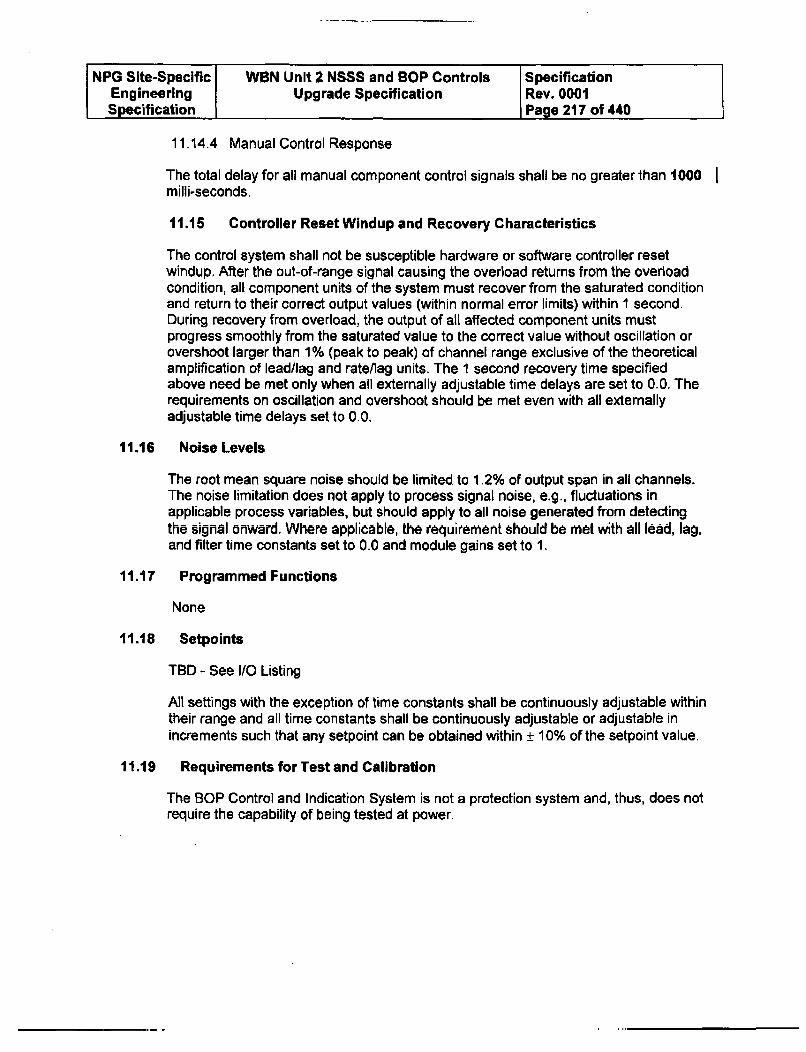
NPG Site-Specific WBN Unit 2 NSSS and BOP Controls SpecificationEngineering Upgrade Specification Rev. 0001Specification Page 217 of 440
11.14.4 Manual Control Response
The total delay for all manual component control signals shall be no greater than 1000milli-seconds.
11.15 Controller Reset Windup and Recovery Characteristics
The control system shall not be susceptible hardware or software controller resetwindup, After the out-of-range signal causing the overload returns from the overloadcondition, all component units of the system must recover from the saturated conditionand return to their correct output values (within normal error limits) within 1 second.During recovery from overload, the output of all affected component units mustprogress smoothly from the saturated value to the correct value without oscillation orovershoot larger than 1% (peak to peak) of channel range exclusive of the theoreticalamplification of lead/lag and rate/lag units. The 1 second recovery time specifiedabove need be met only when all externally adjustable time delays are set to 0.0. Therequirements on oscillation and overshoot should be met even with all externallyadjustable time delays set to 0.0.
11.16 Noise Levels
The root mean square noise should be limited to 1,2% of output span in all channels.The noise limitation does not apply to process signal noise, e.g., fluctuations inapplicable process variables, but should apply to all noise generated from detectingthe signal onward. Where applicable, the requirement should be met with all lead, lag,and filter time constants set to 0.0 and module gains set to 1.
11.17 Programmed Functions
None
11.18 Setpoints
TBD - See I/O Listing
All settings with the exception of time constants shall be continuously adjustable withintheir range and all time constants shall be continuously adjustable or adjustable inincrements such that any setpoint can be obtained within ± 10% of the setpoint value.
11.19 Requirements for Test and Calibration
The BOP Control and Indication System is not a protection system and, thus, does notrequire the capability of being tested at power.
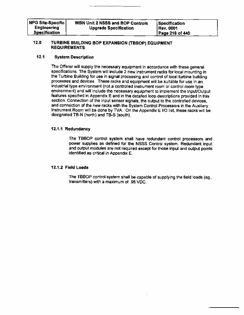
NPG Site-Specific WBN Unit 2 NSSS and BOP Controls SpecificationEngineering Upgrade Specification Rev. 0001Specification Page 218 of 440
12.0 TURBINE BUILDING BOP EXPANSION (TBBOP) EQUIPMENT
REQUIREMENTS
12.1 System Description
The Offerer will supply the necessary equipment in accordance with these generalspecifications. The System will include 2 new instrument racks for local mounting inthe Turbine Building for use in signal processing and control of local turbine buildingprocesses and devices. These racks and equipment will be suitable for use in anindustrial type environment (not a controlled instrument room or control room typeenvironment) and will include the necessary equipment to implement the Input/Outputfeatures specified in Appendix E and in the detailed loop descriptions provided in thissection. Connection of the input sensor signals, the output to the controlled devices,and connection of the new racks with the System Control Processors in the AuxiliaryInstrument Room will be done by TVA. On the Appendix E I/O list, these racks will bedesignated TB-N (north) and TB-S (south).
12.1.1 Redundancy
The TBBOP control system shall have redundant control processors andpower supplies as defined for the NSSS Control system. Redundant inputand output modules are not required except for those input and output pointsidentified as critical in Appendix E.
12.1.2 Field Loads
The TBBOP control system shall be capable of supplying the field loads (eg.,transmitters) with a maximum of 95 VDC.
NPG Site-Specific WBN Unit 2 NSSS and BOP Controls SpecificationEngineering Upgrade Specification Rev. 0001Specification Page 219 of 440
12.2 Instrument Rack Specifications
12.2.1 General Rack Requirements
Two free standing instrument racks (TB-S and TB-N) shall be furnished ofstandard dimensions for mounting 19 inch rack style equipment. The rackwill be large enough to house typical rack style signal processing equipmentincluding space for terminal blocks suitable for landing typical field cables.The rack shall be large enough to house the specified required I/O devicesincluded in this Specification plus room for future expansion of otherequipment. Approximate dimensions will be 30 inches deep by 90 inchestall, but any standard cabinet of similar dimensions will be suitable. Theracks will include both front and rear doors. Terminal blocks shall beprovided in each compartment for field termination of 120V AC power supplycables and input and output cables. Wiring from terminal blocks to functionmodules and power supply modules shall be provided as part of the System.Separate terminal blocks shall be provided for 120V AC power supply wiringand instrument wiring. Two rows of full height terminal blocks shall beprovided for future expansion. All terminals shall be readily accessible whenthe back door of each rack is opened.
NPG Site-Specific WBN Unit 2 NSSS and BOP Controls SpecificationEngineering Upgrade Specification Rev. 0001Specification Page 220 of 440
12.2.2 Internal wiring requirements
Contractor shall give prime consideration to the prevention of fire whendesigning or selecting components and/or materials. Material shall not beused which would support combustion or cause the propagation of a fire.Non-metallic components such as terminal blocks, wire and cable insulation,circuit boards, wire troughs, resistors, capacitors, cable ties, and switchesshall be manufactured from materials which do not burn or are flameretardant as defined in IEEE Std 384-81 and are self-extinguishing asdefined by IEEE Std 420-73. Polyvinyl chloride (PVC) shall not be used forwire insulation and cable jackets. For 120V AC power circuits wheremaximum current does not exceed 5 amperes, minimum wire size shall be14 AWG. Instrument wiring and power wiring shall be separately bundledand be adequately supported to prevent sagging and breakage in transit andwhile in service. Bending radius of wires shall be in accordance with ICEArequirements for the specified wires. Each wire shall be cut so that wiremanufacturer permanent marking is visible at its terminal block end. Allwires shall be terminated by crimped, insulated ring-tongue type terminals.Alternate termination mechanisms may be used with the approval of WVA.Each wire shall be provided with suitable wire markers near its terminals forwire number identification. All terminal blocks shall be rated not less than600V with barriers. Each terminal block shall be provided with a wiremarking strip and terminal block cover secured onto the terminal block bynonferrous material. Termination of each field wire shall be made atseparate terminal screw. The terminal screws shall be not less than No. 10.Wiring shall be arranged to enable function modules and power supplymodules to be removed and/or serviced without unduly disturbing the wiring.No wire shall be routed across the modules in a manner which will impede orobstruct terminals.
NPG Site-Specific WBN Unit 2 NSSS and BOP Controls SpecificationEngineering Upgrade Specification Rev. 0001Specification Page 221 of 440
12.2.3 Detailed Rack Physical Requirements
Each compartment shall have two vent openings, one at the bottom and thesecond at the top, for effective natural convection of heat produced byequipment. All vent openings shall be covered by EMI screen or honeycombto prevent the entrance or exit of RFI. Door and front openings of thecompartments shall be designed so that each 19-inch cabinet can beremoved straight out without twisting and turning. The rack configurationshall allow for both top and bottom cable entry. The exact configuration ofthe cable access openings and conduit bulkhead fittings will be suppliedupon submittal of the rack drawings. Each compartment door shall be madeof one steel plate with edges turned back and rounded for rigidity. Door shallbe flushed, equipped with concealed hinges, latches and 3-point lock. Thelock shall be CCL Security Products 15766, 3 point Tee handle with chromefinish, or equal. All hinged doors shall have a flexible conductor bonded tothe cabinet and door to ensure good electrical conductivity. Gaskets fordoors and removable plates shall be provided. The gaskets shall beelectrically conductive EMI type. Sheet steel used in the panel constructionshall not be less than No. 11 gauge (0.12 inch) in thickness with sufficientstructural reinforcement to assure a plane surface, to limit vibration and toprovide rigidity. The panel base shall be designed for flat surface mounting.Minimum height of the bottom of the lowest compartment to the floor shall besix (6) inches. The panel shall be provided with removable lifting eyes forlifting of the panel complete with all six fully functional 19-inch cabinets.Contractor shall submit outline dimensional drawings and structural detaildrawings of the panel.
12.2.4 Finishing, Painting and Shipping Requirements
After fabrication, all manufacturer waste shall be removed from theequipment. All external and internal cast iron carbon steel and low alloysteel surfaces shall, as a minimum, be protected by application of one coatof primer and two coats of finish paint. All surfaces to be coated shall beprepared for priming by blast cleaning in accordance with the applicableSteel Structures Painting Council Specification. Primer shall be appliedwithin eight (8) hours after blast cleaning and before rusting occurs.Application of primer shall be in accordance with Federal Specification T"-P-664. After air dried, a first and second coat of alkyd enamel shall be appliedper Federal Specification TT-E-508. The enamel shall be in accordance withFederal Standard No. 595a, Color No. 34410, light green. All grease, chalk,crayon, paint marks and other deleterious materials shall be removed frominterior and exterior surfaces. At time of shipment equipment shall be cleaninside and outside. All electrical and electronic equipment and partsincluding 19-inch cabinets shall be wrapped and sealed in plastic for weatherprotection during shipment and while in storage. Desiccant shall be used toprevent moisture build-up in sealed packages.
NPG Site-Specific WBN Unit 2 NSSS and BOP Controls SpecificationEngineering Upgrade Specification Rev. 0001Specification Page 222 of 440
12.3 Detailed Functional Descriptions
12.3.1 Temperature Control Functions
Many of the control functions in the Turbine Building Racks are temperature controlfunctions where the sensed variable is temperature and the control function is valvemodulation to control a valve position to a selected temperature setpoint. TheSystem input will be a thermocouple or RTD and the output will be a 4 to 20 mAcontrol signal. In all cases, a local control station or a MCR control station will berequired that will emulate a Handstation as outlined in Appendix F. The 1/O listreflects the 14 point I/O list that will provide the Handstation function in addition to thenormal input and output. Refer to Appendix F for a list of the required control stationsand design description. None of these functions are considered critical for thepurposes of this specification. The System will provide power to the field sensor, willinterrogate the field sensor output, and will provide contact output, indication, andcontrol to drive the valve I/P transducer. The required inputs and outputs are listed inAppendix E and the Handstations are listed in Appendix F.
12.3.2 Heater Drain Tank Level Controls
The System will provide level measurement and level control functions for both the #3Heater Drain Tank and the #7 Heater Drain Tank. The control scheme for both tankswill be the same and the following is a description of the control system for one of thetanks. In both cases the System will be required to receive 3 level measurementinputs and provide control signals to 2 control valves. These are considered criticalfunctions for the purposes of this specification. One of the 2 valves provides tank levelcontrol through a normal setpoint control scheme with proportional band and reset bymodulating a control valve in the Heater Drain Tank Pump Discharge Header whichfeeds the Condensate stream. The second valve stays closed until a high level isreached indicating failure of the primary control system. Upon reaching apredetermined high setpoint, the second valve starts opening and dumping a portionof the Pump Suction Header to the Condenser. The control scheme for the secondvalve is proportional band control only. There are also various contact outputs forannunciation and logic. Local Handstations as detailed in Appendix F will be requiredfor all control functions. The required inputs and outputs are listed in Appendix E andthe Handstations will be listed in Appendix F. The System will provide power to thefield sensor, will interrogate the field sensor output, will provide the data to one ormore control room devices, and will provide contact output, indication, and control todrive the valve I /P transducers. The required inputs and outputs are listed inAppendix E and the Handstations are listed in Appendix F.
12.4 Indicators, Status Lights. and Controls
Main Control Room Controls
None
Main Control Room Indication
None
NPG Site-Specific WBN Unit 2 NSSS and BOP Controls SpecificationEngineering Upgrade Specification Rev. 0001Specification Page 223 of 440
12.5 Alarms and Annunciators
Main Control Room Annunciation
See IO listing
Computer Monitoring
The plant computer shall be used to generate alarm conditions. The followinginformation shall be supplied to the computer systems. See I/O listing
12.6 Performance Limits
See section 12.3
12.7 Specific Requirements
None
12.8 Accuracy
Channel accuracy is defined to include the accuracy of the primary element,transmitter, rack modules and any process or environmental effects on field mountedhardware. Rack environmental effects are not included in channel accuracy. Thecontrol accuracy is defined to include the channel accuracy plus the accuracy of anyisolators in the system, the controller accuracy and the actual environmental effects.Repeatability is defined as the closeness of agreement among repeatedmeasurements of the output for the same value of input, under normal operatingconditions over a short period of time (defined below), approaching an operating pointfrom a defined direction. Therefore, repeatability recognizes but does not include anyhysteresis non linearities in the system. The period of time over which the repeatabilityis defined is such that long term component drift is not included.
Accuracy Requirements for Normal and Abnormal Operating Conditions
Digital processing effects such as analog-to-digital conversion, software round-offerror, and digital-to-analog conversion should not contribute any additionalinaccuracies greater than 0.5% of channel span to the uncertainties specified in theabove accuracy requirements.
12.9 Range
TBD - See i/O Listing
NPG Site-Specific WBN Unit 2 NSSS and BOP Controls SpecificationEngineering Upgrade Specification Rev. 0001Specification Page 224 of 440
12.10 Inputs
The TBBOP inputs to the System are specified in Appendix E and are primarilytransmitters. The System must be able to supply power to the devices as noted inAppendix E. The System must be capable of accepting both 10 to 50 mA and 4 to 20mA inputs. The input signals and locations are specified in Appendix E and in thedetailed loop descriptions in Section 12.3.
12.11 Outputs
The System outputs will be to indicating devices, recording devices, bistable outputsfor both annunciation and logic functions, and analog control signals to final controldevices. All outputs and their location are specified in Appendix E and in the detailedloop descriptions that follow.
12.12 Proposed Signal Validation Designs
Input Signal Validation
Critical Control System See Section 12.3.2.
12.13 Time Response
12.13.1lAnti=Aliasing Filtering
The system shall have the capability to implement anti-aliasing for all input signals.This requirement includes all input process channels utilized for control, interlocks,and permissives within the noted system(s), and also applies to interlock andpermissive signals calculated outside of but utilized within the subject loops.
12.13.2 Control Processors Response Time
The control processor response time (from the control system's input module/s tooutput module/s including control system processing time) for all input signals shall notexceed 1000 milli-seconds. This requirement includes all input process channelsutilized for control, interlocks, and permissives within the noted system(s), and alsoapplies to interlock and permissive signals calculated outside of but utilized withinthese loops. This requirement includes all modulating control signals, bistable logic(on/off) control signals, mode signals, and signals to the main control board(indication, status, and alarm/annunciators).
12.13.3Communication Response Time between ControlProcessors
Communication between different Control Processor pairs shall not exceed 1000 milli-seconds for control signals involved in closed loop control.
NPG Site-Specific WBN Unit 2 NSSS and BOP Controls SpecificationEngineering Upgrade Specification Rev. 0001Specification Page 225 of 440
12.13.4Manual Control Response
The total delay for all manual component control signals shall be no greater than 500milli-seconds.
12.14 Controller Reset Windup and Recovery Characteristics
The control system shall not be susceptible hardware or software controller resetwindup, After the out-of-range signal causing the overload returns from the overloadcondition, all component units of the system must recover from the saturated conditionand return to their correct output values (within normal error limits) within I second.During recovery from overload, the output of all affected component units mustprogress smoothly from the saturated value to the correct value without oscillation orovershoot larger than 1% (peak to peak) of channel range exclusive of the theoreticalamplification of lead/lag and rate/lag units. The 1 second recovery time specifiedabove need be met only when all externally adjustable time delays are set to 0.0. Therequirements on oscillation and overshoot should be met even with all externallyadjustable time delays set to 0.0.
12.15 Noise Levels
The root mean square noise should be limited to 1.2% of output span in all channels.The noise limitation does not apply to process signal noise, e.g., fluctuations inapplicable process variables, but should apply to all noise generated from detectingthe signal onward. Where applicable, the requirement should be met with all lead, lag.and filter time constants set to 0.0 and module gains set to 1.
12.16 Programmed Functions
None
12.17 Setpoints
TBD - See I/O Listing
All settings with the exception of time constants shall be continuously adjustable withintheir range and all time constants shall be continuously adjustable or adjustable inincrements such that any setpoint can be obtained within ± 10% of the setpoint value.
12.18 Requirements for Test and Calibration
The TBBOP Control System is not a protection system and, thus, does not require thecapability of being tested at power.
NPG Site-Specific WBN Unit 2 NSSS and BOP Controls SpecificationEngineering Upgrade Specification Rev. 0001Specification Page 226 of 440
13.0 SHIPMENT AND STORAGE
13.1 Marking and Identification
Cartons, shipping crates, or skid mounted equipment prepared for shipment shall bemarked as required by the applicable carrier's rules, regulations, statutes, and thepurchase order. Any individually packaged items shall be marked with the name ofthe vendor, the model, component, or part number, and the purchaser's contract andrequisition numbers. Shipping containers shall be marked with the item description,quantities and weight, purchase order number, name and address of the supplier,name and address of the consignee, and the TVA contract number.
The Offerer shall submit to TVA at the time of shipment a detailed list of all itemsshipped, their quantities, and their crate location. This list shall be used by theengineer to ensure receipt at the plant site. Failure to provide a complete andadequate shipping list will delay the payment for the items until such time as adetermination of adequate receipt can be made. The additional time required forverification as a result of the vendor's failure to provide the required documentationshall not entitle the vendor to any late charges, fees, or interest payments.
13.2 Preparation For Shipment
The Offerer shall prepare all materials in such a manner as to facilitate handling and toprotect them from damage in transit. The Offerer shall also be responsible for andmake good any arnd all damage due to improper preparation for loading and shipment.Boxes and crates shall have a packing list enclosed showing parts contained therein.Before shipment all finished surfaces shall be coated or otherwise protected with anapproved non-lead rust preventative.
All components and associated spare parts shall be assembled into the largest pieceswhich can be shipped to the jobsite without incurring additional shipping charges.Exceptions can be made with prior approval of the Engineer.
13.3 Shipping Notice
Shipping notices are required for any delivery. The shipping notices must arrive 10days ahead of the estimated shipment arrival. These notices must be sent to thepersons listed in the Commercial Terms section entitled Shipping Information andMarking. FAX transmittals 10 days ahead of estimated shipment arrival areacceptable, so long as a copy is sent following the FAX.
Advance notification for all shipments shall be made to the applicable site.
13.4 Storage Requirements
All boxes and packages shall be labeled and shall state the environmentrecommended for their storage, e.g., outside, under roof, minimum and maximumtemperature, and humidity control.
NPG Site-Specific WBN Unit 2 NSSS and BOP Controls SpecificationEngineering Upgrade Specification Rev. 0001Specification Page 227 of 440
13.5 Spare Parts
Spare parts shall be packaged separate from the remainder of the equipment. Theshipping contents shall, in addition to labeling required in Section 13.1, be clearlylabeled as containing spare parts.
13.6 Shipment
The Offerer shall be fully responsible for damage from handling and environmentalconditions during loading and shipment. Each assembly or component of theequipment shall be braced, crated, packed, or otherwise protected so that no damagewill occur in transit, handling, or storage.
Provisions shall be made for lifting and skidding. All lifting points shall be clearlymarked. All accessories, monitoring devices, and packing lists shall be packed andshipped with the equipment.
Shipments shall be made by Air Ride (Air Suspension) exclusively. Truck shipmentswill be accepted weekdays only between the hours of 7:00 a.m. and 1:00 p.m.(Eastern Time) Monday through Friday. After-hour deliveries not provided for bycontract may be refused until the next regular workday.
14.0 DEFINITIONS
The following are definitions of terms that may be used throughout this specification.
Analog Signal - A continuously variable signal which varies across a range of voltageor current.
Architecture (System) - The combination and relationship of hardware, configuration,and communications of any system. The functions and capabilities contained insystems and how they operate with each other.
Bus - A control network topology in which nodes share one single linear medium.Messages propagate the length of the medium and are received by all nodessimultaneously, except for distance considerations.
Common Mode Failure Source - An element of the control system which, when itfails, influences more than one piece of process equipment and inhibits operation ofmore than one out of a group of redundant process parts.
Computer - A logic processing device which performs many calculations sequentially,at high speed.
NPG Site-Specific WBN Unit 2 NSSS and BOP Controls SpecificationEngineering Upgrade Specification Rev. 0001Specification Page 228 of 440
14.0 DEFINITIONS (continued)
Communications Network (Also called a Data Highway) - The mechanism oftransmitting data and commands between independently functioning microprocessors(nodes). A high speed, integrated, communications path capable of detecting thefailure of nodes or the loss of signal integrity and able to recover from these losses. Itshould be fully redundant so that no single fault will cause the loss of communicationof all plant signals. The media for the network may be twisted wire, coax, triax, twinax,or fiber optic cable.
Configuration - The ability of plant personnel to change the engineering andoperational contents of a DCS without the requirement of a programmer. An exampleof a configuration change would be the use of a ODU screen display with fill-in blanksto change a high alarm limit from 1020 degrees to 1025 degrees.
Offerer, Vendor, Contractor, Supplier - Provider of the materials or services and anysubcontracted supplier under this contract.
Cycle time - The time span in which the inputs programs (algorithms) and outputs insystem is updated.
Data Base - The collection of stored data regarding the process variable programsand processing procedures.
Datalink - The use of a communications path to send more than one signal. Datalinkscommonly use an RS 232-C serial cable which passes messages slowly according toa standard originally designed to allow computers to send print messages to printers.
Drop - An intelligent device performing specific functions that communicate throughthe node or the communications network and or subnetworks. Typical functions aredata acquisition, monitoring, calculation, logging, controlling, printing, interfacing, etc.A drop performs tasks without central supervision.
Detailed Functional Specifications - The detailed requirements and descriptions ofthe operation of the system as well as procedures and agreements as to developmentof the system provided by the Offerer.
Distributed Processing - Organizational mode of operation in which multipleprocessors are working concurrently or non-concurrently, each with their own memoryand are connected by a network.
Engineer - The term "Engineer" or "Technical Engineer" is the Site Lead ElectricalEngineer or their designee who is the point of contact for all technical issues. Furtherdefinition may be supplied in the special conditions section of the contract.
Failure - Whenever the external behavior of a system (to the process) does notconform to the expected system's specified performance.
Fault - Any abnormal event within the system, or malfunction in hardware or software.
NPG Site-Specific WBN Unit 2 NSSS and BOP Controls SpecificationEngineering Upgrade Specification Rev. 0001Specification Page 229 of 440
14.0 DEFINITIONS (continued)
Fault Tolerance - The quality of a system to assure functional integrity in the event ofa component (hardware or software) fault. The ability to prevent failure of the systemupon a fault in the system.
Functional Area - A functional area is a location, such as the control room, where allactions and annunciation need to be coordinated on all ODU screens and similardisplays. A functional area would not be affected by actions in another functionalarea.
Functional Distribution - The ability to place control functions, such as the control ofeach SG Level, in a separate microprocessor or group of microprocessors operatingas a single entity called a node. With this approach, each mill operates autonomouslysuch that a failure of one of the nodes should not affect the ability of the other mills(nodes) to continue operations.
Functional Capacity - The number of I/O points on a card that may be used by theControl System. The maximum limit under is contract is 16 points/card regardless ofthe capability of the card.
Global Time - The time elapsed between the moment an external event triggers asystem reaction and the moment the system actuates a processed response.
Hard Control - Hard control is the use of dedicated switches, indicators, and controlstations for each device.
Hardware Cutoff - The date when TVA's ability to change I/O, node, or otherhardware requirements without effecting delivery or price ends.
Hard Wire - Connecting and running dedicated wires between pieces of equipment,usually to communicate information or control commands. One wire communicatesone (and only one) piece of information or command.
Input/Output (110) Points - The hard wired signals into or out of any C&MS.
Main Frame - A large computer that can handle multiple tasks concurrently
Mean Time to Detection (MTTD) - The elapsed time (in hours) between theoccurrence of a fault until it is detected by the service personnel. The MIUI'D dependson the technique used by the control system for fault detection, and the training ofpersonnel's skills.
Mean Time to Repair (MTTR) - The elapsed time (in hours) to repair a component ora system after a fault has been detected,
Medium Access Control - The method of determining which node has access to thenetwork or sub-network.
NPG Site-Specific WBN Unit 2 NSSS and BOP Controls SpecificationEngineering Upgrade Specification Rev. 0001Specification Page 230 of 440
14.0 DEFINITIONS (continued)
Microcomputer - A computer whose packaging of electronic cards and speed is on asmall scale, such as an IBM microcomputer used for classroom training.
Monitoring - A means of providing automatic performance supervision and alarmingof the status of a plant process through which changes can be made to the status ofthe process through control equipment or operator action.
Multiprocessing - A computer organization mode of operation on a local basis inwhich multiple processors are working concurrently for high availability and/or highcomputing power.
Network Coupler- A device connecting two independent communications networks.
Node - A microprocessor or group of microprocessors that operate synchronously andcan communicate data and/or commands over a communications network. A nodeperforms tasks without central supervision.
Object Code - The instructions comprising a computer program expressed in machinelanguage, being the binary representations which actually cause the computermachinery to execute operations, without regard to whether the instructions areprinted or stored magnetically on tape, disc, or other medium.
Operator - TVA's plant personnel responsible for operating the unit and normally
assigned to the control room.
Owner - Tennessee Valley Authority
Plant Engineer - A technically competent plant person on TVA's staff assigned to theplant.
Point - A value or input in the system. Also a variable, point ID or tag name.
Ring - A topology in which the nodes are linked through point-to-point communicationin a closed loop.
RISC - Reduced Instruction Set Computing: internal computing architecture whereprocessor instructions are pared down so that most can be performed in a singleprocessor cycle, theoretically improving computing efficiency.
RoHS - See web link http://www.rohs.gov.uk - Restriction of Hazardous Substances.
Scan Time - The interval between successive readings of a field input, includingprocessing and reporting.
Serial Interface - Usually, as pertains to computers or terminals, the mechanical andelectrical components that allow data to be sent sequentially-by-bit over atransmission medium; in contrast to parallel interface.
NPG Site-Specific WBN Unit 2 NSSS and BOP Controls SpecificationEngineering Upgrade Specification Rev. 0001Specification Page 231 of 440
14.0 DEFINITIONS (continued)
Soft Control - The use of ODU screens and keyboards for the direct operatorinterface to the process equipment (through to the final control actuators). Each ODUlocation can perform any one of the many control functions (i.e., stations, switches,indicators, etc.) that are presently located on the existing control panel.
Software - The computer programs which are a part of the System, are provided bythe CONTRACTOR to "VA in accordance with the terms of the Contract Documents.
Software Cutoff - The date all program and configuration requirements become finaland cannot be changed without effecting delivery or price.
Soft Wire - The use of a network to send and receive commands and information. Nodedicated wires or connections to hardware exist.
Source Code - The instructions comprising a computer program expressed in thesystem programming language, without regard to whether the instructions are printedor stored magnetically on tape, disc, or other medium.
Starian - A local area network design and specification within the IEEE 802.3standards subcommittee, characterized by I-Mbit/s baseband data transmission overtwo-pair wiring.
Star A topology in which the nodes are linked through a common point; either active
or passive, such that loss of this central point causes loss of that network.
Sub-network - Serial network connecting nodes or communicating modules.
Switched Line - Communications link for which the physical path, established bydialing, may vary with each use.
Synchronous Transmission - Data communications where characters or bits aresent at a fixed rate with the transmitting and receiving devices synchronized.
System - The DCS and the equipment and software covered by the ContractDocuments.
System Documentation - All printout specifications, file specifications, data basedictionary in file sequence, flow charts, ODU screen formats, report formats, and alldocuments which collectively contain a complete description and definition of alloperating conditions of, and all maintenance requirements and procedures for all partsof the System, and all user guides describing the operation and management of theSystem.
Systems Network Architecture - The layered logical structure, formats, protocols,and procedures that govern information transmission.
Tree - A topology derived from the bus by branching the bus through active or passivesplitters.
NPG Site-Specific WBN Unit 2 NSSS and SOP Controls SpecificationEngineering Upgrade Specification Rev. 0001Specification Page 232 of 440
14.0 DEFINITIONS (continued)
Terminal - A point in a network at which data can either enter or leave; usuallyequipped with keyboard, often with a display, capable of sending and receiving dataover a communications link.
Token Ring - A local network access mechanism and topology in which a supervisoryframe or token is passed from station to station in sequential order; stations wishing togain access to the network must wait for the token to arrive before transmitting data; ina token ring, the next logical station receiving the token is also the next physicalstation on the ring.
TVA Representative - A TVA Engineer or their designee who is the point of contactfor coordinating Owner-witnessed events or materials inspection visits.
15.0 AUXILLIARY CONTROL ROOM EQUIPMENT REQUIREMENTS
15.1 System Description
A separate, stand alone control system shall be provided to replace existing analogmodules and hand control stations locating in existing panels in the Auxilliary ControlRoom (ACR). This equipment is intended to provide an alternate location to controlcertain loops if the Main Control Room (MCR) is uninhabitable. Accordingly, thissystem shall operate independently of the rest of the system described in the rest ofthis document, and shall not require the availability of any equipment outside the ACRto operate. It is desired that the engineering workstation located in the Aux InstrumentRoom not be required for loading the configuration when both controller processorspower up; offerer shall state if this is required.
None of this equipment is safety related, but there are train associations as shown inthe I/O list (Appendix G). A pair of control processors and associated I/O shall beprovided for each train. Train A and B hardware will be physically separated.
15.1.1 Redundancy
The ACR control system shall have redundant control processors and power supplies.Redundant input and output modules are not required.
15.2 System Functional Details
The ACR loops have been grouped into several generic categories. Specific loopdetails may be found in the I/O listing (Appendix G), which references these sections.
15.2.1 Indicator Loops
A number of the ACR Loops serve only to provide readout data for the operator onpanel 2-L-1 0. The System will provide power to the field sensor, will interrogate thefield sensor output, and will provide the data to one or more control room devices-The required signals and locations are tabulated in Appendix G0
NPG Site-Specific WBN Unit 2 NSSS and BOP Controls SpecificationEngineering Upgrade Specification Rev. 0001Specification Page 233 of 440
15.2.2 Display and Contact Output Loops
A number of the ACR Loops provide readout data for the operator on panel 2-L-10and in addition, provide contact outputs for input to externally developed logic,annunciation and/or status lights. The System will provide power to the field sensor ifrequired, will interrogate the field sensor output, will provide the data to one or morecontrol room devices, and will provide contacts that will change status atpredetermined setpoints. The required signals, contact outputs, and locations aretabulated in Appendix G.
15.2.3 Alternate Controller Loops
Some of the ACR loops provide an alternate control loop for loops in the MCRIAIR.For each loop, a switch is located in the ACR on panel 2-L-1-A or 2-L-11B to allowthe operator to select either the MCR as the control location or the ACR as the controllocation. The switch simply selects which output goes to the control valve. Where atransmitter is included in the loop, standard PID control is required with a single inputfrom a transmitter and a single output to a valve. Other loops are hand loadingstations only. Hand control stations shall be provided as shown in the I/O list, toreplace existing controllers. The required signals and locations are tabulated inAppendix G.
15.3 Time Response
16.3.1 Anti-Aliasing Filtering
The system shall have the capability to implement anti-aliasing for all input signals.This requirement includes all input process channels utilized for control, interlocks,and permissives within the noted system(s), and also applies to interlock andpermissive signals calculated outside of but utilized within the subject loops.
15.3.2 Control Processors Response Time
The control processor response time (from the control system's input module/s tooutput module/s including control system processing time) for all input signals shall notexceed 500 milli-seconds. This requirement includes all input process channelsutilized for control, interlocks, and permissives within the noted system(s), and alsoapplies to interlock and permissive signals calculated outside of but utilized withinthese loops. This requirement includes all modulating control signals, bistable logic(on/off) control signals, mode signals, and signals to the main control board(indication, status, and alarm/annunciators).
16.3.3 Communication Response Time between ControlProcessors
Communication between different Control Processor pairs shall not exceed 500 milli-seconds for control signals involved in closed loop control.
NPG Site-Specific WBN Unit 2 NSSS and BOP Controls SpecificationEngineering Upgrade Specification Rev. 0001Specification Page 234 of 440
15.3.4 Manual Control Response
The total delay for all manual component control signals shall be no greater than 500milli-seconds.
15.4 Controller Reset Windup and Recovery Characteristics
The control system shall not be susceptible to hardware or software controller resetwindup. After the out-of-range signal causing the overload returns from the overloadcondition, all component units of the system must recover from the saturated conditionand return to their correct output values (within normal error limits) within 1 second.During recovery from overload, the output of all affected component units mustprogress smoothly from the saturated value to the correct value without oscillation orovershoot larger than 1% (peak to peak) of channel range exclusive of the theoreticalamplification of lead/lag and rate/lag units. The 1 second recovery time specifiedabove need be met only when all externally adjustable time delays are set to 0.0. Therequirements on oscillation and overshoot should be met even with all externallyadjustable time delays set to 0.0.
15.5 Noise Levels
The root mean square noise should be limited to 1.2% of output span in all channels.The noise limitation does not apply to process signal noise, e.g., fluctuations inapplicable process variables, but should apply to all noise generated from detectingthe signal onward. Where applicable, the requirement should be met with all lead, lag,and filter time constants set to 0.0 and module gains set to 1.
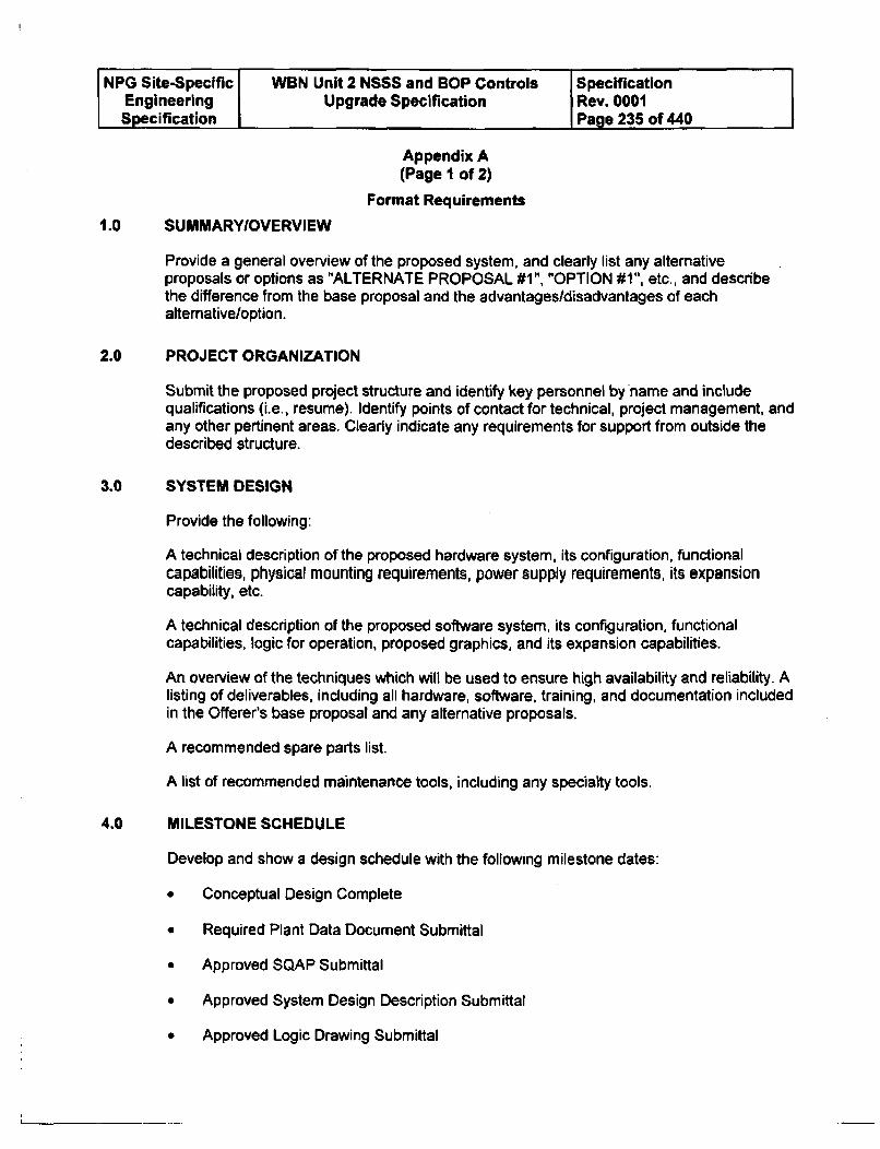
NPG Site-Specific WBN Unit 2 NSSS and BOP Controls SpecificationEngineering I Upgrade Specification Rev. 0001Specification I Page 235 of 440
Appendix A
(Page I of 2)
Format Requirements
1.0 SUMMARYIOVERVIEW
Provide a general overview of the proposed system, and clearly list any alternativeproposals or options as "ALTERNATE PROPOSAL #1", "OPTION #1", etc., and describethe difference from the base proposal and the advantages/disadvantages of eachalternative/option.
2.0 PROJECT ORGANIZATION
Submit the proposed project structure and identify key personnel by name and includequalifications (i.e., resume). Identify points of contact for technical, project management, andany other pertinent areas. Clearly indicate any requirements for support from outside thedescribed structure.
3.0 SYSTEM DESIGN
Provide the following:
A technical description of the proposed hardware system, its configuration, functionalcapabilities, physical mounting requirements, power supply requirements, its expansioncapability, etc.
A technical description of the proposed software system, its configuration, functionalcapabilities, logic for operation, proposed graphics, and its expansion capabilities.
An overview of the techniques which will be used to ensure high availability and reliability. Alisting of deliverables, including all hardware, software, training, and documentation includedin the Offerer's base proposal and any alternative proposals.
A recommended spare parts list.
A list of recommended maintenance tools, including any specialty tools.
4.0 MILESTONE SCHEDULE
Develop and show a design schedule with the following milestone dates:
* Conceptual Design Complete
* Required Plant Data Document Submittal
* Approved SQAP Submittal
* Approved System Design Description Submittal
* Approved Logic Drawing Submittal
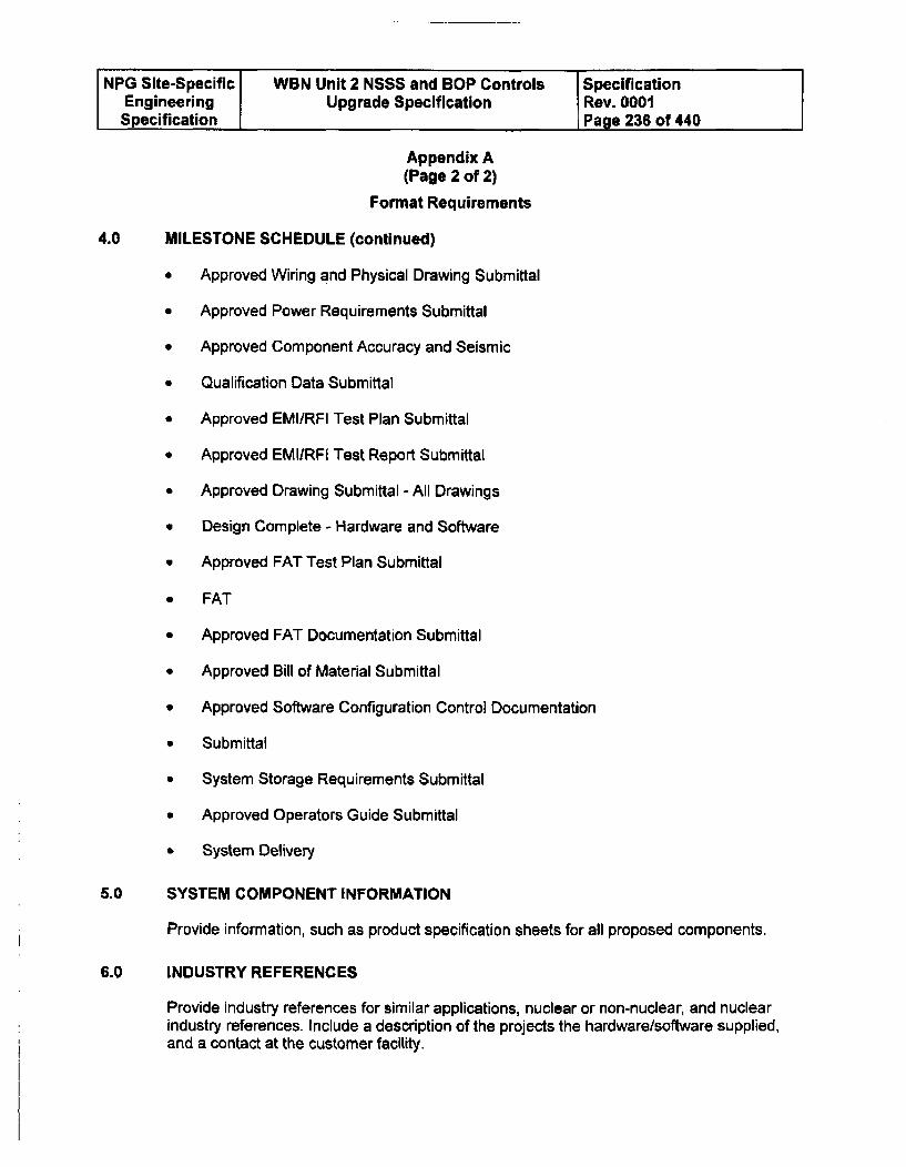
NPG Site-Specific WBN Unit 2 NSSS and BOP Controls SpecificationEngineering Upgrade Specification Rev. 0001Specification Page 236 of 440
Appendix A(Page 2 of 2)
Format Requirements
4.0 MILESTONE SCHEDULE (continued)
* Approved Wiring and Physical Drawing Submittal
* Approved Power Requirements Submittal
* Approved Component Accuracy and Seismic
* Qualification Data Submittal
* Approved EMI/RFI Test Plan Submittal
* Approved EMIIRFI Test Report Submittal
* Approved Drawing Submittal - All Drawings
" Design Complete - Hardware and Software
* Approved FAT Test Plan Submittal
* FAT
* Approved FAT Documentation Submittal
* Approved Bill of Material Submittal
* Approved Software Configuration Control Documentation
* Submittal
* System Storage Requirements Submittal
" Approved Operators Guide Submittal
" System Delivery
5.0 SYSTEM COMPONENT INFORMATION
Provide information, such as product specification sheets for all proposed components.
6.0 INDUSTRY REFERENCES
Provide industry references for similar applications, nuclear or non-nuclear, and nuclearindustry references. Include a description of the projects the hardware/software supplied,and a contact at the customer facility.
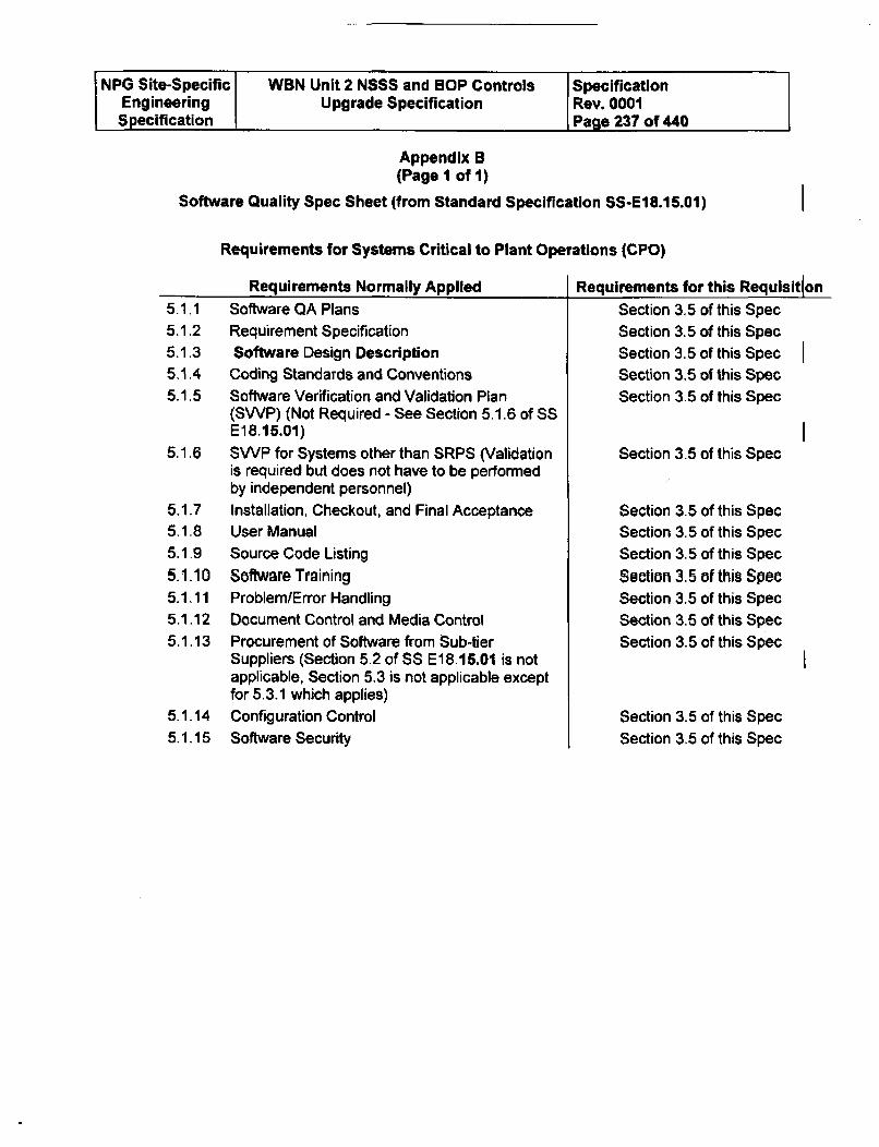
NPG Site-Specific WBN Unit 2 NSSS and BOP Controls SpecificationEngineering Upgrade Specification Rev. 0001Specification Page 237 of 440
Appendix B(Page I of 1)
Software Quality Spec Sheet (from Standard Specification SS-E18.15.01)
Requirements for Systems Critical to Plant Operations (CPO)
Requirements Normally Applied Requirements for this Requisition5.1.1 Software QA Plans5.1.2 Requirement Specification5.1.3 Software Design Description5.1.4 Coding Standards and Conventions5.1.5 Software Verification and Validation Plan
(SWP) (Not Required - See Section 5.1.6 of SSE18.15.01)
5.1.6 SWP for Systems other than SRPS (Validationis required but does not have to be performedby independent personnel)
5.1.7 Installation, Checkout, and Final Acceptance5.1.8 User Manual5.1.9 Source Code Listing
5.1.10 Software Training5.1.11 Problem/Error Handling5.1.12 Document Control and Media Control
5.1.13 Procurement of Software from Sub-tierSuppliers (Section 5.2 of SS E18.16.01 is notapplicable, Section 5.3 is not applicable exceptfor 5.3.1 which applies)
5.1.14 Configuration Control5.1.15 Software Security
Section 3.5 of this SpecSection 3.5 of this SpecSection 3.5 of this SpecSection 3.5 of this SpecSection 3.5 of this Spec
Section 3.5 of this Spec
Section 3.5 of this SpecSection 3.5 of this Spec
Section 3.5 of this Spec
Section 3.5 of this SpecSection 3.5 of this SpecSection 3.5 of this SpecSection 3.5 of this Spec
Section 3.5 of this SpecSection 3.5 of this Spec
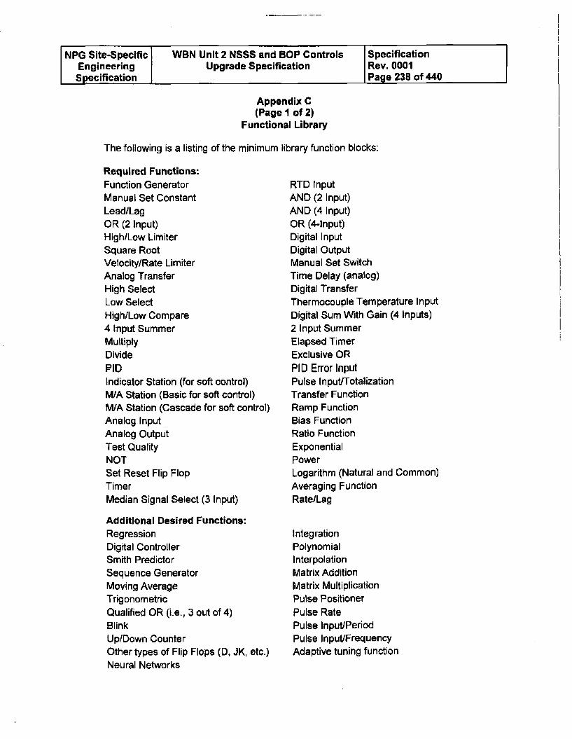
NPG Site-Specific WBN Unit 2 NSSS and BOP Controls SpecificationEngineering Upgrade Specification Rev. 0001Specification Page 238 of 440
Appendix C(Page 1 of 2)
Functional Library
The following is a listing of the minimum library function blocks:
Required Functions:Function GeneratorManual Set ConstantLead/LagOR (2 Input)High/Low LimiterSquare RootVelocity/Rate LimiterAnalog TransferHigh SelectLow SelectHigh/Low Compare4 Input SummerMultiplyDividePIDIndicator Station (for soft control)M/A Station (Basic for soft control)M/A Station (Cascade for soft control)Analog InputAnalog OutputTest QualityNOTSet Reset Flip FlopTimerMedian Signal Select (3 Input)
Additional Desired Functions:RegressionDigital ControllerSmith PredictorSequence GeneratorMoving AverageTrigonometricQualified OR (i.e., 3 out of 4)BlinkUp/Down CounterOther types of Flip Flops (D, JK, etc.)Neural Networks
RTD InputAND (2 Input)AND (4 Input)OR (4-Input)Digital InputDigital OutputManual Set SwitchTime Delay (analog)Digital TransferThermocouple Temperature InputDigital Sum With Gain (4 Inputs)2 Input SummerElapsed TimerExclusive ORPID Error InputPulse Input/TotalizationTransfer FunctionRamp FunctionBias FunctionRatio FunctionExponentialPowerLogarithm (Natural and Common)Averaging FunctionRate/Lag
IntegrationPolynomialInterpolationMatrix AdditionMatrix MultiplicationPulse Positioner
Pulse RatePulse Input/PeriodPulse Input/FrequencyAdaptive tuning function
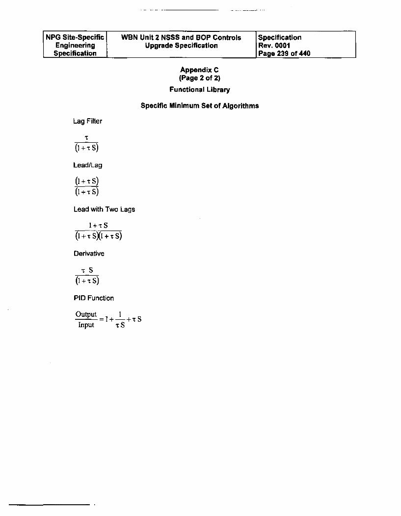
NPG Site-Specific WBN Unit 2 NSSS and BOP Controls SpecificationEngineering Upgrade Specification Rev. 0001Specification Page 239 of 440
Appendix C(Page 2 of 2)
Functional Library
Specific Minimum Set of Algorithms
Lag Filter
(i + -C S)
Lead/Lag
( + , s)(I + E s)
Lead with Two Lags
1+tS
( + - sXi + s)
Derivative
-rS
( + - S)
PID Function
Output =+ +
Input T S
NPG Site-Specific WBN Unit 2 NSSS and BOP Controls SpecificationEngineering Upgrade Specification Rev. 0001Specification Page 240 of 440
Appendix D(Page 1 of 7)
WBN Simulator Requirements
The following Appendix is being added to better define the WBN Simulator upgrademodification requirements.
Simulator Requirements for Process Panel and BOP panel replacements.
1.0 Introduction
The Watts Bar simulator is certified per the requirements of ANSI 3.5 as required by10CFR55. This certification requires that operators receive training and testing on asimulator that looks and behaves in the same manner as the actual plant in both normal,abnormal, and accident conditions. Concerning the installation of the plant instrumentpanels, it is our goal to ensure that the quality of simulator fidelity remains at least as goodas if not better than the present simulation.
There are two broad areas of simulation that must be considered. The first is theman/machine interface (panel hardware requirements or operator controls and displays) onthe main trainer. The second is modeling the algorithms (software modeling and controlrequirements) that describe the internal operation of the new instrument panels. These twofunctional areas are divided to explain more fully the requirements for each.
7.0 Panel Hardware Requirements
The simulator panels shall have the same look and "feel" as the plant. The requirementsare:
A. The Offerer shall provide necessary simulator switches, controls, and panels toreplicate those to be installed in Main Control Room and/or Auxiliary Control Room onexisting simulator panels.
B. The Offerer shall supply two spares of each type of simulator hardware; i.e. ODU,keyboard, indicators, switches, control stations, etc. for new or custom equipment.Spares for standard equipment such as VX-252 meters need not be included.
C. These controls shall be of the type that will interface with the present simulator i/Oequipment. Simulator analog outputs are 0-10VDC @lma, analog inputs are 0-10V,and relay or lamp outputs are 20VDC@500ma. Digital inputs are simple dry contactclosure (current sinking, 3.35VDC open circuit voltage, 1.25VDC threshold voltage).
NPG Site-Specific WBN Unit 2 NSSS and BOP Controls SpecificationEngineering Upgrade Specification Rev. 0001Specification Page 241 of 440
Appendix D
(Page 2 of 7)
WBN Simulator Requirements
7.0 Panel Hardware Requirements (continued)
D. MCR Controllers can be simulated or stimulated. In the simulated case, the paneldevice is simply a false front with appropriate dials, indicators, and switches that drivethe software emulation of the controller function. In the simulated case, the Offererwould disclose full descriptions of the algorithms used, including limits, controllercharacteristics, rates, gains, etc. to ensure full fidelity. In the stimulated case, theactual controller would be mounted to the simulator panel with appropriate IO to makeit fully functional. The controller would be the identical model to that installed in theplant, with the exception that qualification for seismic events and radiation exposure isnot required The controller will then be set to identical tuning factors as the plant. Ineither case, each would have to meet the requirements listed in the software modelingand control requirements for initialization, snapshots, backtracks, etc. Either methodwould be satisfactory and the best way to simulate the proposed system is at Offererdiscretion.
8.0 Software Modeling and Control Requirements
Software shall be provided for two simulation systems: the simulation system with the panelsattaehed and the develoirment systemr without panels attached. The functions of theproposed process cabinets and BOP racks shall be fully replicated in the WBN simulator toensure fidelity. All simulator commands, such as fast time, real time, slow time, reset, freezerun, snapshot, etc. are to be accepted from the existing simulator computer. The Offerershall specify in detail how the proposed equipment will respond to these commands,especially with regard to the Snap and Backtrack functions and the format and methodologyof saving and resetting to a given state. The Reset feature must be able to reset to a savedcondition with complete initialization for the saved condition. No effects from a previoussimulator run must be carried over to the new reset condition. The requirements are:
A. The simulator must be able to freeze the process. This includes being able to freezethe time sensitive devices such that timing functions and integration do not continue.Placing the simulator into run from freeze shall continue the process in the samemanner as if the freeze had not occurred.
B. The software must be able to snapshot and reset to at least 1000 different initialconditions (ICs 0-999) When resetting to an IC after making a snapshot, the simulatormust be able to resume simulation regardless of the condition of timing functions, suchas controller integration values, signal conditioning values (lags, rates, etc). That is, theprocess shall be continuous with data prior to the snapshot. Snapshots shall be takenupon demand from the simulator before any calculations begin in order to ensureconsistency of data between the simulator models and the digital feedwater software.
NPG Site-Specific WBN Unit 2 NSSS and BOP Controls SpecificationEngineering Upgrade Specification Rev. 0001Specification Page 242 of 440
Appendix D(Page 3 of 7)
WBN Simulator Requirements
8.0 Software Modeling and Control Requirements (continued)
C. The simulator must be able to provide at least 60 backtrack records in a cyclical typefile such that the simulator may be reset to a previous point with a backtrack interval of15 seconds to 5 minutes, with a nominal value of 1 minute. This enables instructors tobacktrack the simulator to anywhere in the last hour of operation using a backtrackrecording rate of 1 minute. Backtrack records shall be taken upon demand from thesimulator before any calculations begin. The process of making the backtrack recordshall not cause a visible pause in the execution of the simulation.
D. The simulation must be able to run in real time, fast time, and slow time. This mayrequire changing the iteration rate rather than program time constants if necessary tomaintain source code equivalence with the plant implementation of functionalcalculations and algorithms. Specifically, the normal real time execution of thesimulator consists of 12 frames per second. A slow time factor of up to 24 may beapplied, in which case the simulator executes the appropriate number of frames persecond. Due to limitations of the simulator's core/RCS model, a fast time factor of nomore than 2 is possible, in which case 24 frames per second would be executed.Synchronization of the simulation software and digital feedwater system executionrates shall ensure that both systems maintain the same time rate.
E. The simulator must fully simulate the failure conditions expected in the plant-bothsingle and multiple failures. This includes but is not limited to loss of power, CPUlockups, analog output failures, analog input failures, etc. The Offerer shall providemalfunction hooks as necessary in his software to perform these functions.
F. Upon removal of a malfunction to a failed simulated component, the simulator must beable to replicate the same response as would occur in the plant, such as changingoutputs, alarms, etc. As an example, on a loss of power, a lead-lag module may havea step change in its output when power is restored and could impact a control system itis connected to in a negative way. The simulator must respond similarly.
G. The simulated process cabinets must have the same gains, time constants, logic, andfailure modes as the system in the plant. A user interface must exist to modifyparameters that can be field tuned in plant equipment.
H. There must be capability to modify or upgrade the software based upon changes inplant design, setpoints, time constants and other functions as necessary. There mustbe a method available to add malfunctions or remote functions to the code necessaryto support future training needs, such as unforeseen problems that will requiresimulator training in the future.
1. The digital feedwater system shall accept a command from the simulator to erase alltrend information. This would typically be used during license exams where the recallof trends from previous scenarios has the potential to compromise the exam. Afterreceipt of this command, no past history of parameter trends shall be available from thepanel mounted GUI displays.
NPG Site-Specific WBN Unit 2 NSSS and BOP Controls SpecificationEngineering Upgrade Specification Rev. 0001Specification Page 243 of 440
Appendix D(Page 4 of 7)
WBN Simulator Requirements
8.0 Software Modeling and Control Requirements (continued)
J. The incorporation of changes to the plant digital feedwater software into the simulatorenvironment shall not invalidate existing simulator initial conditions. WVA recognizesthat addition of new components to the plant software may result in those componentsnot being initialized in the proper state for each simulator initial condition. Thisrequirement means that the state of all existing components shall be preserved in orderto minimize the initial condition stabilization required after incorporation of plantsoftware changes on the simulator.
K. The software for the simulator development computer shall be able to run properlywithout the panel hardware attached in order to allow software testing anddevelopment when the simulator panels are not available. Initial conditions shall beportable between the simulation and development environments.
L. TVA engineers must have the capability to monitor and change internal variables thatare important to the operation of the digital feedwater system for debugging andtroubleshooting purposes.
M. If the plant digital feedwater systern, is to be interfaced directly to the plant Integrated
Computer System (ICS), the simulator digital feedwater system software must providethe same computer points for transmission to the simulator ICS.
9.0 Implementation Requirements
These modeling requirements can be implemented in two general ways. They may be fullysimulated by the Offerer in the present WBN simulator computer, or they may be simulatedusing a stand alone computer running the same software as the plant. TVA engineers willassist the Offerer, if necessary, in the modification of existing simulator software to provideinputs that are not currently available or to rescale outputs as needed. Regardless of whichoption is chosen, the interfacing software which executes in the existing simulation anddevelopment computers shall be compatible with the Wafts Bar OpenSim simulationenvironment and shall be developed under Microsoft Visual Studio version 6.0. All sourcecode and Developer Studio files necessary to build the interfacing task shall be supplied toTVA. Certain include files and libraries necessary to compile and link the interfacingprogram will be provided by TVA. The Offerer shall not modify these files in any way. Thelist of variables to be transferred shall be defined by a text file (or group of files) editable withany standard text editor. Modification of the file(s) and restarting the software shall besufficient to redefine the list of variables to be transferred.
The general requirements for each simulation option are described below:
NPG Site-Specific WBN Unit 2 NSSS and BOP Controls SpecificationEngineering Upgrade Specification Rev. 0001Specification Page 244 of 440
Appendix D(Page 5 of 7)
WBN Simulator Requirements
9.0 Implementation Requirements (continued)
A. Simulation in the present simulator computer.
Under this option, all software necessary to run the digital feedwater system wouldexecute in the existing simulator and development computers. An interfacing taskwould execute under the OpenSim executive and transfer necessary inputs, outputsand state variables to and from the digital feedwater software which executes outsidethe OpenSim executive. If this option is chosen, the execution of the digital feedwatersoftware shall not cause the rest of the simulation software to fail to execute on a realtime basis.
B. Simulation of the new system on a standalone computer.
Under this option, the present simulator software models would supply inputinformation to another computer(s) supplied by the Offerer and the simulator computerwould accept output data from this computer. An interfacing task, similar in functionand identical in requirements to that described under option (a) would communicatewith the standalone computer. This computer would utilize the identical softwaresource code as the plant processors for the functional calculations and algorithms suchthat fidelity is assured. Simulator-specific control routines external to these routinesmay be used. All timing relationships must be maintained for independent processesas in the plant processors regardless of series/parallel execution differences. Simulatorcommunication to and from the new standalone computer(s) (eg, TCP/IP with Ethernetconnections) must be compatible with existing simulator hardware and software.Documentation for hardware and software requirements and protocols for interfacingwith the existing simulation computer must be provided in detail.
The Offerer shall provide two simulated computer systems with supporting hardware: one tobe used on the main simulator trainer and the other for simulation engineering development.
10.0 Documentation Requirements
Manufacturer and vendor documentation for supplied hardware including configurationdrawings of vendor packaging of equipment shall be supplied. Documentation of thehardware and software system, including content description and procedures for modifyingand rebuilding the software system, shall be provided.
The Offerer shall provide, at a minimum, the following hardware documentation in the form
of two printed and two electronic copies:
List of all parts required for installation into the simulator panels
List of all required cables for connection to the computer room
List of any required computer room interfacing equipment
I NPG Site-Specific WBN Unit 2 NSSS and BOP Controls SpecificationEngineering Upgrade Specification Rev. 0001Specification Page 245 of 440
Appendix D
(Page 6 of 7)
WBN Simulator Requirements
10.0 Documentation Requirements (continued)
Interconnection diagrams detailing the proper connection of all panel instruments to thecomputer room equipment
The Offerer shall provide, at a minimum, the following software documentation in the form oftwo printed and two electronic copies:
Description of the interfacing program which runs under the SimPort environment, includingthe structure of the message buffers used to transfer information to and from the digitalfeedwater system
Description of the format of the text file(s) used to specify the variables transferred to andfrom the digital feedwater system
Procedures for updating the simulator digital feedwater system for changes made in theplant
Description of the organization and layout of initial condition and backtrack snapshots
11.0 Schedule
All plant simulator hardware, software, and documentation shall be delivered as specified inthe Commercial portion of this solicitation.
12.0 Licensing, Support, Training and Warranty
Licensing fees for the simulator computer and development computer shall be included inthe total price for the supplied digital feedwater simulation. The seller shall also provide aprice quote per individual license for running the digital feedwater simulation on computersother than the simulator computer and development computer, as well as any availablediscounted license fees for running on multiple computers. TVA may choose to purchaseadditional licenses to allow use of the software on classroom computers.
On site technical support of the installation of simulator components must be provided. Onsite training for installation and maintenance of the simulator equipment must also beprovided. The training shall include, at a minimum, the following:
* Starting and stopping the software
* Modifying the interface configuration file(s), including explanation of the file(s) format
" Incorporation of plant configuration changes into the simulator
* Monitoring and changing internal variables
* Establishment and stabilization of simulator initial conditions
NPG Site-Specific WBN Unit 2 NSSS and BOP Controls SpecificationEngineering Upgrade Specification Rev. 0001Specification Page 246 of 440
Appendix D(Page 7 of 7)
WBN Simulator Requirements
12.0 Licensing, Support, Training and Warranty (continued)
A warranty period, one year at a minimum, shall be established after delivery during whichthe Offerer shall provide technical support.
13.0 Testing requirements
The simulator system provided by the Offerer must be able to meet the requirementsspecified in this bid specification for snapshots, resets, etc. In addition, the Offerer shallprovide necessary plant startup test data to the WBN simulator group so that the simulatorcan be verified to respond like the plant in each instrument process that is upgraded per therequirements of ANSI-3.5 1998. Offerer shall ensure that plant design changes as a result ofplant or simulator implementation and installation are incorporated into the simulatorsoftware and/or hardware.
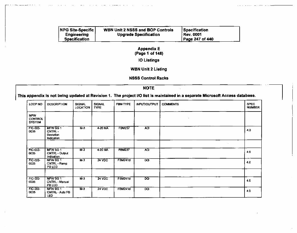
NPG Site-Specific WBN Unit 2 NSSS and BOP Controls SpecificationEngineering Upgrade Specification Rev. 0001Specification Page 247 of 440
Appendix E(Page 1 of 148)
10 Listings
WBN Unit 2 Listing
NSSS Control Racks
This appendix is not being updated at Revision
NOTE
1. The project I/O list is maintained in a separate Microsoft Access database.
LOOP NO DESCRIPTION SIGNAL SIGNAL FBM TYPE INPUT/OUTPUT COMMENTS SPECLOCATION TYPE NUMBER
MFWCONTROLSYSTEM
FIC-003- MFW SG I M-3 4-20 MA FBM237 AO0035 CNTRL - 4.0
DeviationIndication
FIC-003- MFW SG 1 M-3 4-20 MA FBM237 A 4.0035 CNTRL - Output 4.0
IndicationFIC-003- MFW SG 1 M-3 24 VDC FBM241d DO0035 CNTRL - Ramp 4.0
PB LED
FIC-003- MFW SG 1 M-3 24 VDC FBM241d DO40035 CNTRL - Manual 4.0
PB LEDFIC-003- MFW SG 1 M-3 24 VDC FBM241d DO 4.00035 CNTRL - Auto PB
LED
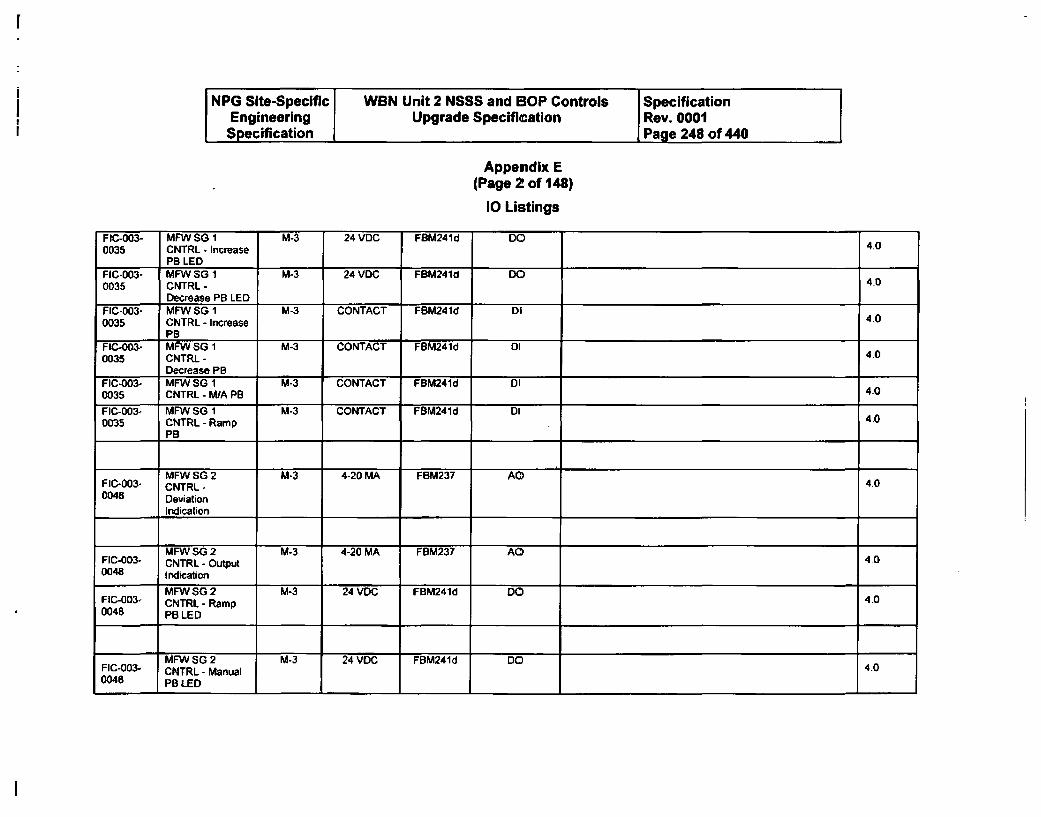
NPG Site-Specific WBN Unit 2 NSSS and BOP Controls SpecificationEngineering Upgrade Specification Rev. 0001
Specification Page 248 of 440
Appendix E(Page 2 of 148)
10 Listings
FIC-003- MFW SG 1 M-3 24 VDC FBM241d DO0035 CNTRL - Increase 4.0
PB LEDFIC-003- MFW SG 1 M-3 24 VDC FBM241d DO0035 CNTRL - 4.0
Decrease PB LEDFIC-003- MFW SG 1 M-3 CONTACT FBM241d DII0035 CNTRL - increase 40
PBFIC-003- MFW SG 1 M-3 CONTACT FBM241d DI00035 CNTRL- 4.0
Decrease PBFIC-003- MFW SG 1 M-3 CONTACT FBM241d DI0035 CNTRL - M/A PB 4.0
FIC-003- MFW SG 1 M-3 CONTACT FBM241d DI0035 CNTRL - Ramp 4.0
PB
MFW SO 2 M-3 4-20 MA FBM237 AO4FIC-003- CNTRL- 4.0
0048 Deviation
Indication
MFW SG 2 M-3 4-20 MA FBM237 AOFIC-003- CNTRL - Output 4.00048 Indication
MFW SG 2 M-3 24 VDC FBM241d DOFIC-003- CNTRL - Ramp 4.00048 PB LED
MFW SG 2 M-3 24 VDC FBM241d DO 4.0FIC-003ý CNTRL - Manual0048 PB LED
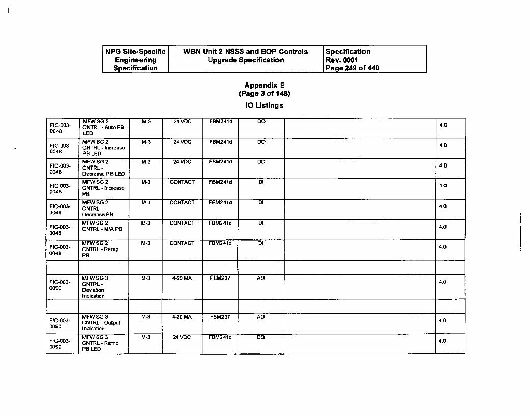
NPG Site-Specific WBN Unit 2 NSSS and BOP Controls SpecificationEngineering Upgrade Specification Rev. 0001Specification Page 249 of 440
Appendix E(Page 3; of 148)
10 Listings
MFWSG2 M-3 24 VDC FBM241d DO4FIC-003- CNTRL - Auto PB 4.00048 LED
MFW SG 2 M-3 24 VDC FBM241d DO 4.0FIC-003- CNTRL - Increase0048 PB LED
MFWSG2 M-3 24 VDC FBM241d DOFIC-003- CNTRL - 4.00048 Decrease PB LED
MFW SG 2 M-3 CONTACT FBM241d DIFIC-003- CNTRL - Increase 400048 PB
MFW SG 2 M-3 CONTACT FBM241d DIFIC-003- CNTRL- 4.00048 Decrease PB
MFW SG 2 M-3 CONTACT FBM241d DIFIC-003- CNTRL - MfA PB 4.00048
MFW SG 2 M-3 CONTACT FBM241d DIFIC-003- CNTRL - Ramp 4.00048 PB
MFW SG 3 M-3 4-20 MA FBM237 AD A.FIC-003- CNTRL - 4.00090 Deviation
Indication
MFW SG 3 M-3 4-20 MA FBM237 ADF1C-003- CNTRL - Output 4.00090 Indication
MFW 0SG3 M-3 24VDC FBM241d DO4F1C-003- CNTRL - Ramp 4.00090 PB LED
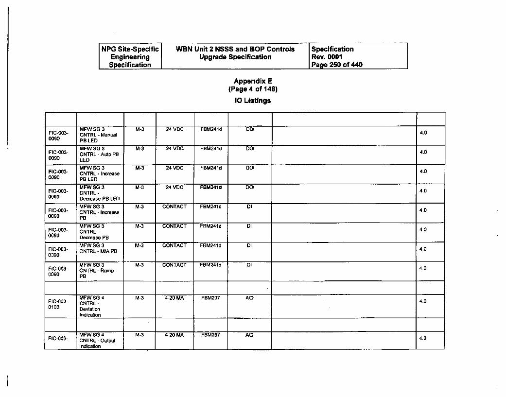
NPG Site-Specific WBN Unit 2 NSSS and BOP Controls SpecificationEngineering Upgrade Specification Rev. 0001Specification Page 250 of 440
Appendix E(Page 4 of 148)
10 Listings
MFWSG 3 M-3 24 VDC FBM241d DO4FIC-O03- CNTRL - Manual 4.00090 PB LED
MFW SG 3 M-3 24 VDC FBM241d DO)FIC-003- CNTRL - Auto PB 4.00090 LED
MFW SG 3 M-3 24 VDC FBM241d DO4FIC-003- CNTRL - Increase 4.00090 PB LED
MFW SG 3 M-3 24 VDC FBM241d DOFIC-003- CNTRL - 4.00090 Decrease PB LED
MFW SG 3 M-3 CONTACT FBM241d 0lFIC-003- CNTRL - Increase 4.00090 P
MFW SG 3 M-3 CONTACT FBM241d DIFIC-003- CNTRL- 4.00090 Decrease PB
MFW SO 3 M-3 CONTACT FBM241d DIFIC-003- CNTRL - M/A PB 400090
MFW SG 3 M-3 CONTACT FBM241d DIFIC-003- CNTRL - Ramp 4.00090 PB
MFW SG 4 M-3 4-20 MA FBM237 AO4FIC-003- CNTRL - 4.00103 Deviation
Indication
MFW SG 4 M-3 4-20 MA FBM237 AO 4.0
FIC-003- CNTRL - Output
Indication
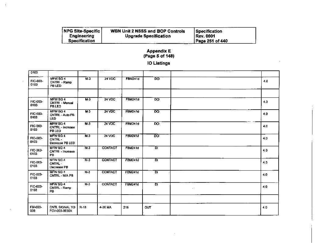
NPG Site-Specific WBN Unit 2 NSSS and BOP Controls SpecificationEngineering Upgrade Specification Rev. 0001Specification I Page 251 of 440
Appendix E(Page 5 of 148)
10 Listings
0103
MFW SG 4 M-3 24 VDC FBM241 d DOFIC-003- CNTRL - Ramp 4.00103 PB LED
MFWSG4 M-3 24 VDC FBM241d DOFIC-003- CNTRL - Manual 4.00103 PB LED
MFW SG 4 M-3 24 VDC FBM241d DOFIC-003- CNTRL - Auto PB 4.00103 LED
MFW SG 4 M-3 24 VDC FBM241d DOFIC-003- CNTRL - Increase 4.00103 PB LED
MFW SG 4 M-3 24 VDC FBM241d DOFIC-003- CNTRL - 4.00103 Decrease PB LED
MFW SG 4 M-3 CONTACT FBM241d DIFIC-D03- CNTRL - Increase 4.00103 PB
MFW SG 4 M-3 CONTACT FBM241d DIFIC-003- CNTRL - 4.00103 Decrease PB
MFW SG 4 M-3 CONTACT FBM241d DIFIC-003- CNTRL - MIA PB 4.00103
MFW SG 4 M-3 CONTACT FBM241d DIFIC-003- CNTRL - Ramp 4.00103 PB
FM-003- CNTL SIGNAL TO R-16 4-20 MA 218 OUT 4.0035 FCV-003-0035A
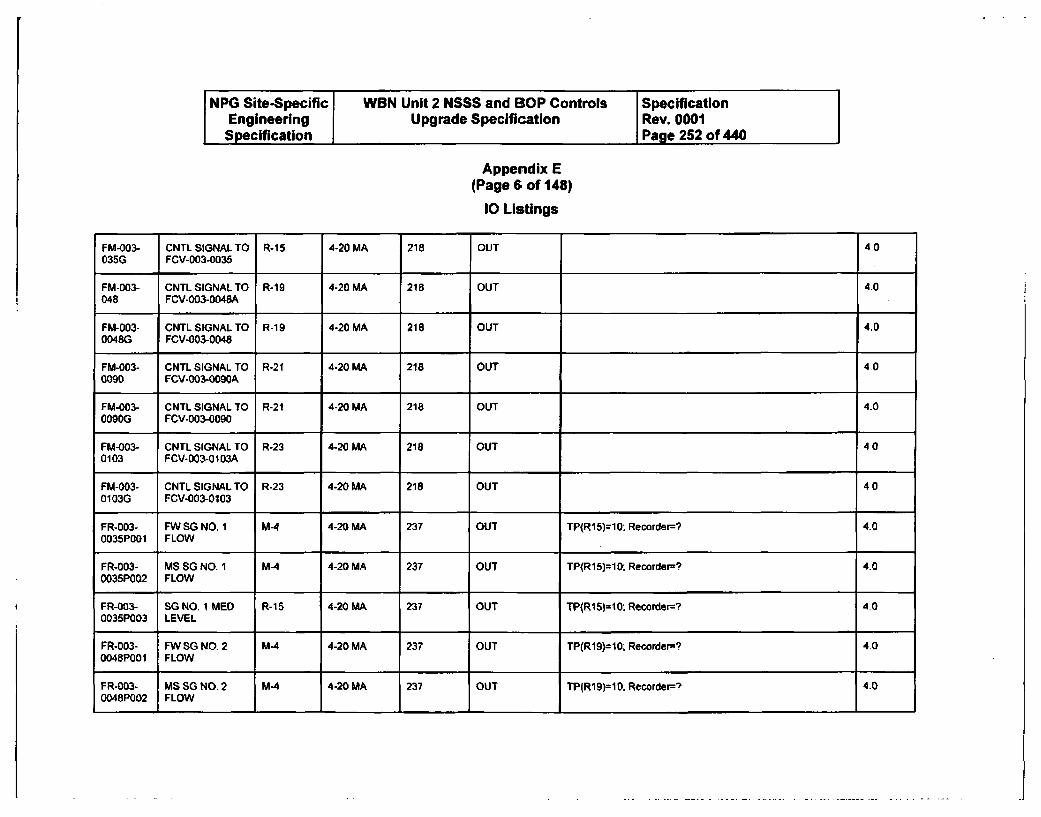
NPG Site-Specific WBN Unit 2 NSSS and BOP Controls SpecificationEngineering Upgrade Specification Rev. 0001Specification Page 252 of 440
Appendix E(Page 6 of 148)
10 Listings
FM-003- CNTL SIGNALTO R-15 4-20 MA 218 OUT 4.0035G FCV-003-0035
FM-003- CNTLSIGNALTO R-19 4-20 MA 218 OUT 4.0048 FCV-003-0048A
FM-003- CNTLSIGNALTO R-19 4-20 MA 218 OUT 4.00048G FCV-003-0048
FM-003- CNTL SIGNAL TO R-21 4-20 MA 218 OUT 4.00090 FCV-003-0090A
FM-003- CNTL SIGNAL TO R-21 4-20 MA 218 OUT 4-00090G FCV-003-0090
FM-003- CNTL SIGNAL TO R-23 4-20 MA 218 OUT 400103 FCV-003-0103A
FM-003- CNTL SIGNAL TO R-23 4-20 MA 218 OUT 400103G FCV-003-0103
FR-003- FW SG NO. 1 M4 4-20 MA 237 OUT TP(R15)=10: Recorder--? 4.00035P001 FLOW
FR-003- MS SG NO. 1 M-4 4-20 MA 237 OUT TP(R15)=10; Recorder-? 4.00035P002 FLOW
FR-003- SG NO. 1 MED R-15 4-20 MA 237 OUT TP(R15)=10. Recorder? 4.00035P003 LEVEL
FR-003- FW SG NO. 2 M-4 4-20 MA 237 OUT TP(R19)=10; Recorder? 4.00048P001 FLOW
FR-003- MS SG NO. 2 M-4 4-20 MA 237 OUT TP(R19)=10; Recorder=? 4.00048P002 FLOW
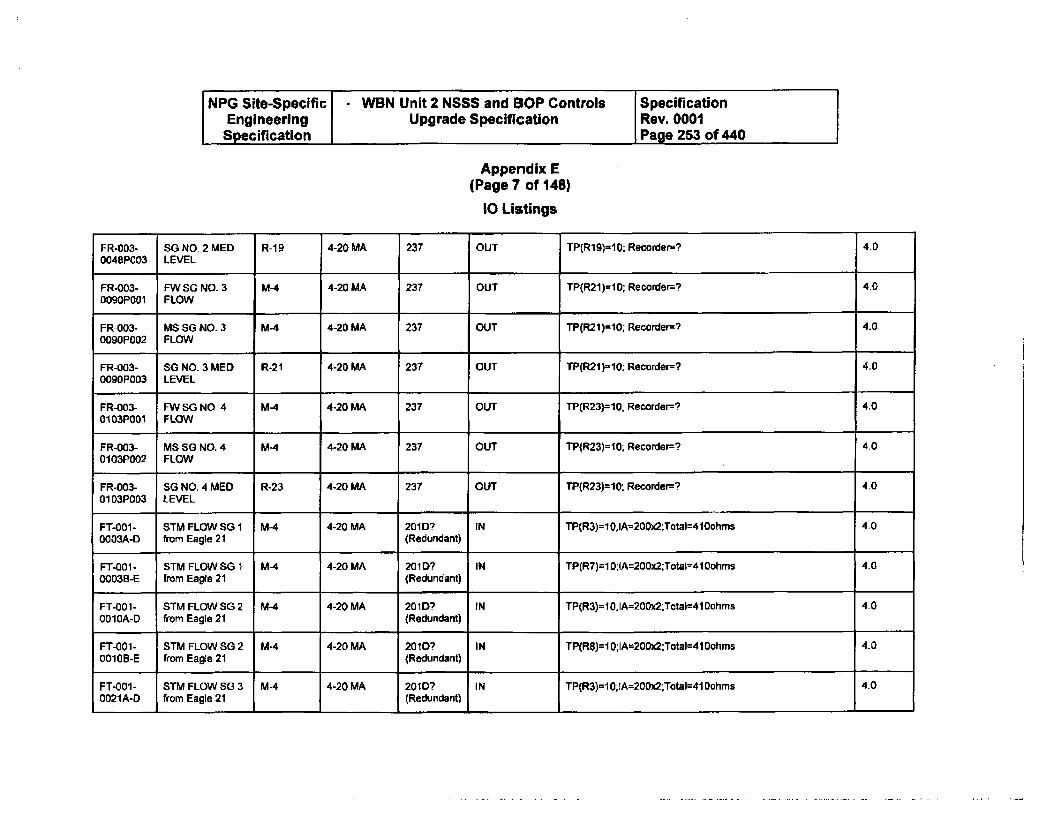
NPG Site-Specific -WBN Unit 2 NSSS and SOP Controls SpecificationEngineering Upgrade Specification Rev. 0001Specification Page 253 of 440
Appendix E(Page 7 of 148)
1O Listings
FR-003- SG NO 2 MED R-19 4-20 MA 237 OUT TP(R19)=10; Recorder=? 4.00048P003 LEVEL
FR-003- FWSG NO. 3 M-4 4-20 MA 237 OUT TP(R21)=10; Recorder-? 4.0D09OPOOl FLOW
FR-003- MS SG NO. 3 M-4 4-20 MA 237 OUT TP(R21)=10; Recorder-? 4.00090P002 FLOW
FR-003- SG NO 3 MED R-21 4-20 MA 237 OUT TP(R21)l10; Recorder-? 4.00090P003 LEVEL
FR-003- FW SG NO 4 M4 4-20 MA 237 OUT TP(R23)=10. Recorder? 4.00103POOl FLOW
FR-003- MS SG NO. 4 M-4 4-20 MA 237 OUT TP(R23)=10; Recorder-? 4.00103P002 FLOW
FR-003- SG NO. 4 MED R-23 4-20 MA 237 OUT TP(R23)=10: Recorder-? 4.00103P003 LEVEL
FT-00I- STM FLOW SG I M-4 4-20 MA 2010? IN TP(R3)=10;IA=200x2:Total=410ohms 4.00003A-D from Eagle 21 (Redundant)
FT-001- STM FLOW SG 1 M4 4-20 MA 201D? IN TP(R7)=10;IA=200x2;Total=410ohms 4.00003B-E from Eagle 21 (Redundant)
FT-001- STM FLOW SG 2 M-4 4-20 MA 201D1 IN TP(R3)=10;IA=200x2;Tctal=410ohms 4.00010A-D from Eagle 21 (Redundant)
FT-001- STM FLOW SG 2 M-4 4-20 MA 2010? IN TP(R8)=10;IA=200x2:Total=410ohms 4.0001OB-E from Eagle 21 (Redundant)
FT-001- STM FLOW SG 3 M-4 4-20 MA 201D? IN TP(R3)=10;lA=200x2;Total=41Dohms 4.00021A-D from Eagle 21 (Redundant)
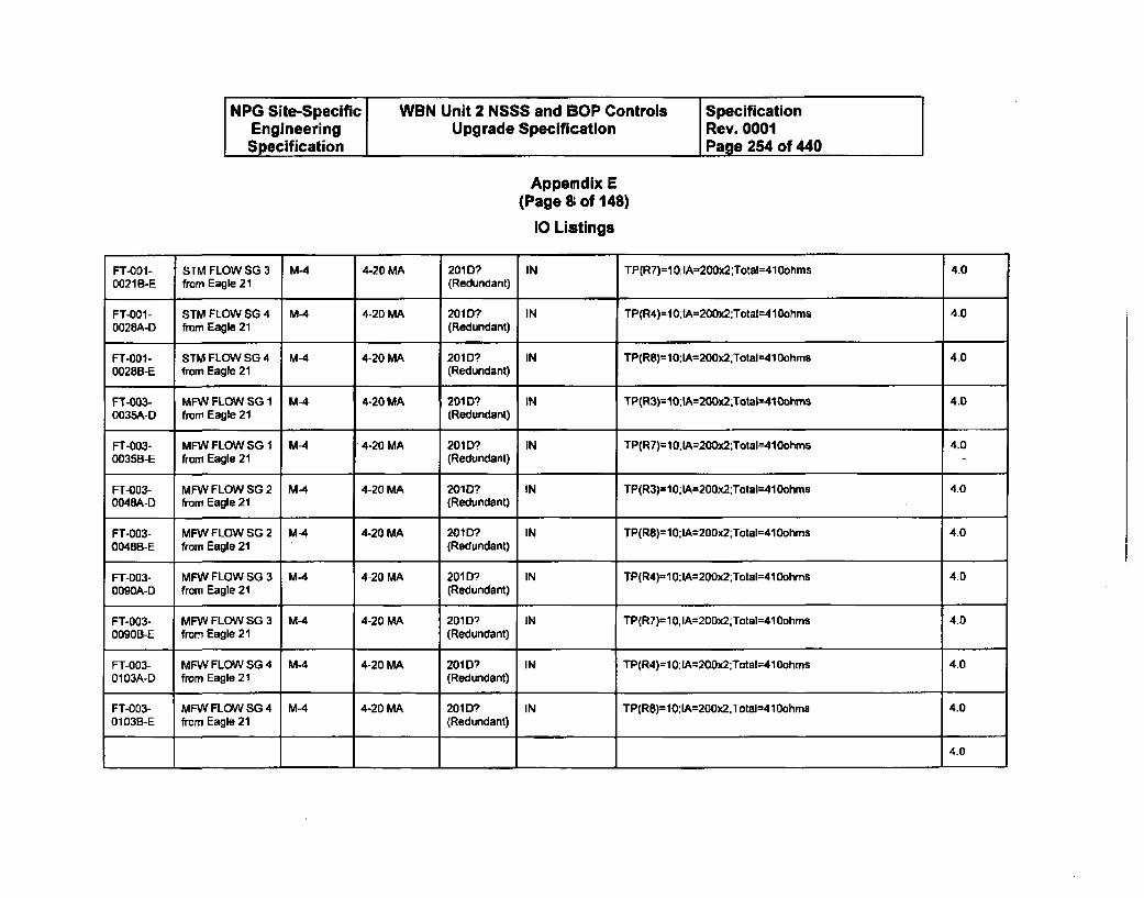
NPG Site-Specific WBN Unit 2 NSSS and SOP Controls SpecificationEngineering Upgrade Specification Rev. 0001Specification Page 264 of 440
Appendix E(Page 8 of 148)
10 Listings
FT-001- STM FLOW SG 3 M-4 4-20 MA 201D? IN TP(R7)=10;IA=200x2;Total=410ohms 4.00021B-E from Eagle 21 (Redundant)
FT-001 - STM FLOW SG 4 M-4 4-20 MA 201 D? IN TP(R4)=10;IA=200x2:Total=410ohms 4.00028A-D fmm Eagle 21 (Redundant)
FT-00- STM FLOW SG 4 M-4 4-20 MA 20103? IN TP(R8)= 10;A=200x2.Total=410ohms 4.00028B-E from Eagle 21 (Redundant)
FT-003- MFW FLOW SG I MA 4-20 MA 2010? IN TP(R3)=10:lA=20Ox2.Total=410ohms 4.00035A-D from Eagle 21 (Redundant)
FT-003- MFW FLOW SG i MA 4-20 MA 201D? IN TP(R7)=10;IA=200x2;Total=410ohms 4.0O035B-E from Eagle 21 (Redundant)
FT-003- MFW FLOW SG 2 M4 4-20 MA 201D? IN TP(R3)=10;lA=200x2;Total=410ohms 4.00048A-D from Eagle 21 (Redundant)
FT-003- MFW FLOW SG 2 MA 4-20 MA 2010? IN TP(R8)=10:IA=200x2;Total-410ohms 4.00048B-E from Eagle 21 (Redundant)
FT-003- MFW FLOW SG 3 M-4 4-20 MA 201D? IN TP(R4)=10;OA=20x2;Tatal=410ohms 4.00090A-D from Eagle 21 (Redundant)
FT-003- MFW FLOW SG 3 MA 4-20 MA 2010? IN TP(R7)=10;A=200x2;TotaI=410ohms 4.00090B-E from Eagle 21 (Redundant)
FT-003- MFW FLOW SG 4 M-4 4-20 MA 201D? IN TP(R4)=10:IA=200x2:TotaI=410ohms 4.00103A-D from Eagle 21 (Redundant)
FT-003- MFW FLOW SG 4 M-4 4-20 MA 201D? IN TP(RB)=10;,IA=200x2,TotaI=41Oohms 4.00103B-E from Eagle 21 (Redundant)
4.0

NPG Site-Specific WBN Unit 2 NSSS and BOP Controls SpecificationEngineering Upgrade Specification Rev. 0001Specification Page 255 of 440
Appeindix E(Page 91 of 148)
10 Listings
MFW SG I M-3 4-20 MA FBM237 ADLIC-003- BYPASS CNTRL- 4.00035A Deviation
IndicationMFW SO 1 M-3 4-20 MA FBM237 AD4
LIC-003- BYPASS CNTRL - 4.00035A6 Setpoint
IndicationMFW SG 1 M-3 4-20 MA FBM237 AO)LIC-003- BYPASS CNTRL - 4.0
0035A Output Indication
MFW SG 1 M-3 24 VDC FBM241d DO4LIC-003- BYPASS CNTRL - to0035A Ramp PB LED
MFW SG 1 M-3 24 VDC FBM241d DO4LIC-003- BYPASS CNTRL - 4.00035A Setpoint PB LED
MFWSG 1I M-3 24 VDC FBM241d DO)LIC-003- BYPASS CNTRL - 4.00035A Manual PB LED
MFW SG 1 M-3 24 VDC FBM241d DO4LIC-003- BYPASS CNTRL - 4.00035A Auto PB LED
MFW SG 1 M-3 24 VDC FBM241d DO4LIC-003- BYPASS CNTRL - 400035A Increase PB LED
MFW SG 1 M-3 24 VDC FBM241d DOLIC-003- BYPASS CNTRL - 4.00035A Decrease PB LED
MFW SG 1 M-3 CONTACT FBM241d DILIC-003- BYPASS CNTRL - 4.00035A Increase PB
MFW SG 1 M-3 CONTACT FBM241d DILIC-003- BYPASS CNTRL - 4.00035A Decrease PB
MFWS G 1 M-3 CONTACT FBM241d DILIC-003- BYPASS CNTRL - 4.0
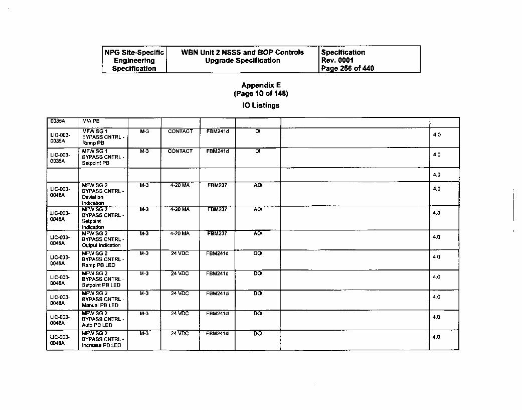
NPG Site-Specific WBN Unit 2 NSSS and BOP Controls SpecificationEngineering Upgrade Specification Rev. 0001Specification Page 256 of 440
Appendix E(Page 10 of 148)
10 Listings
0035A MIA PB
MFWSOG I M-3 CONTACT FBM24Id Dl 4.0LIC-003- BYPASS CNTRL -0035A Ramp P8
MFW SG 1 M-3 CONTACT FBM241d DILIC-003- BYPASS CNTRL -0035A Setpoint PB
4.0
MFW SG 2 M-3 4-20 MA FBM237 AOLIC-003- BYPASS CNTRL - 4.00048A Deviation
IndicationMFW SG 2 M-3 4-20 MA FBIM237 AO4
LIC-003- BYPASS CNTRL - 4.00048A Setpoint
IndicationMFWSG2 M-3 4-20 MA FBM237 AO 4.0
LIC-003- BYPASS CNTRL -0048A Output Indication
MFW SG 2 M-3 24 VDC FBM241d DO4LIC-003- BYPASS CNTRL - 400048A Ramp PB LED
MFW S0 2 M-3 24 VDC FBM241 d DOLIC-003- BYPASS CNTRL - 4.00048A Setpoint PB LED
MFW SG 2 M-3 24 VDC FBM241 d DOLIC-003- BYPASS CNTRL - 4o0048A Manual PB LED
MFW SO 2 M-3 24 VOC FBM241d DOLIC-003- BYPASS CNTRL - 4.00048A Auto PB LED
MFW SG 2 M-3 24 VDC FBM241d DO
LIC-003- BYPASS CNTRL - 4.00048A Increase PB LED
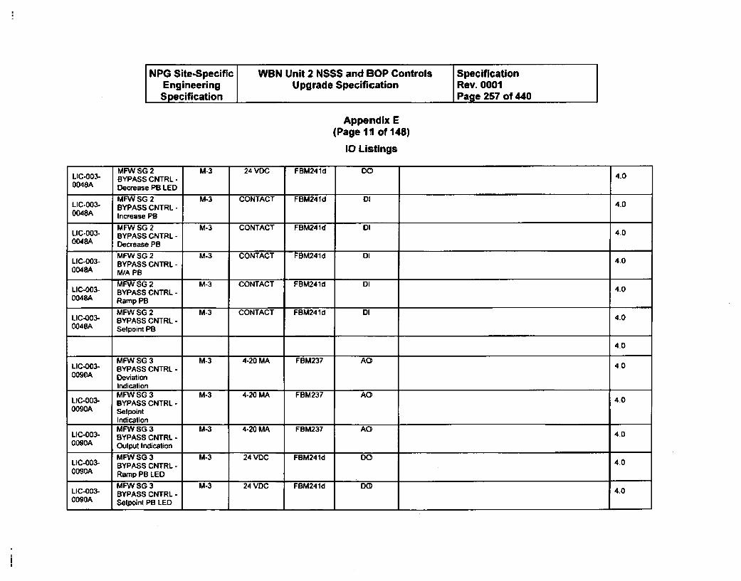
NPG Site-Specific WBN Unit 2 NSSS and BOP Controls SpecificationEngineering Upgrade Specification Rev. 0001Specification Page 257 of 440
Appemdix E(Page li of 148)
10 Listings
MFW SG 2 M-3 24 VDC FBM241d DOLIC-003- BYPASS CNTRL -0048A Decrease PB LED
MFW SG 2 M-3 CONTACT FBM241d DILIC-003- BYPASS CNTRL - 4.00048A Increase PS
MFW SG 2 M-3 CONTACT FBM241d DILIC-003- BYPASS CNTRL - 4.00048A Decrease PB
MFW SG 2 M-3 CONTACT FBM241d DILIC-003- BYPASS CNTRL - 4.00048A M/A PB
MFW SG 2 M-3 CONTACT FBM241d DILIC-003- BYPASS CNTRL - 4.00048A Ramp PS
MFW SG 2 M-3 CONTACT FBM241d DILIC-003- BYPASS CNTRL - 4.00048A Setpoint PB,
4-0
MFW SG 3 M-3 4-20 MA FBM237 AO 40LIC-003- BYPASS CNTRL - 400090A Deviation
IndicationMFW SG 3 M-3 4-20 MA FBM237 AO
LIC-003- BYPASS CNTRL -0090A Setpoint
IndicationMFN SG 3 M-3 4-20 MA FBM237 AO
LIC-003- BYPASS CNTRL - 4.0OD90A Output Indication
MFW SG 3 M-3 24 VDC FBM241d DO 'LIC-003- BYPASS CNTRL - 4.00090A Ramp PB LED
MFW SG 3 M-3 24 VDC FBM241d DOLIC-003- BYPASS CNTRL - 4.00090A Setpoinl PB LED
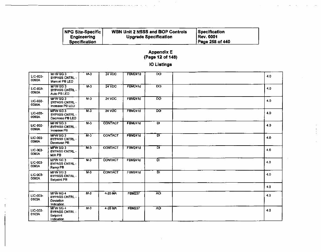
NPG Site-Specific WBN Unit 2 NSSS and BOP Controls SpecificationEngineering Upgrade Specification Rev. 0001Specification Page 258 of 440
Appendix E(Page 12 of 148)
10 Listings
MFW SG 3 M-3 24 VDC FBM24Id DOLIC-003- BYPASS CNTRL - to0090A Manual PB LED
MFW SG 3 M-3 24 VDC FBM241d DOLIC-003- BYPASS CNTRL - 4.00090A Auto PB LED
MFW SG 3 M-3 24 VIDC FBM241d DO 4.0LIC-003- BYPASS CNTRL -0090A Increase PB LED
MFWSG3 M-3 24 VDC FBM241d DOLIC-003- BYPASS CNTRL - 4.00090A Decrease PB LED
MFW SG 3 M-3 CONTACT FBM241d D0LIC-003- BYPASS CNTRL - 400090A Increase PB
MFWSG 3 M-3 CONTACT FBM241d DILIC-003- BYPASS CNTRL - 400090A Decrease PB
MFW SG 3 M-3 CONTACT FBM241d DIL1C-003- BYPASS CNTRL - 40
0090A M/A PB
MFW SO 3 M-3 CONTACT FBM241d DiLIC-003- BYPASS CNTRL- 400090A Ramp PB
MFW SG 3 M-3 CONTACT FBM241d DILIC-003- BYPASS CNTRL - 40O090A Setpoint PB
4.0
MFW SG 4 M-3 4-20 MA FBM237 AC 4.0LIC-003- BYPASS CNTRL -0103A Deviation
IndicationMFW SG 4 M-3 4-20 MA FBM237 AO4
[IC-003- BYPASS CNTRL - 4.00103A Setpoint
I Indication
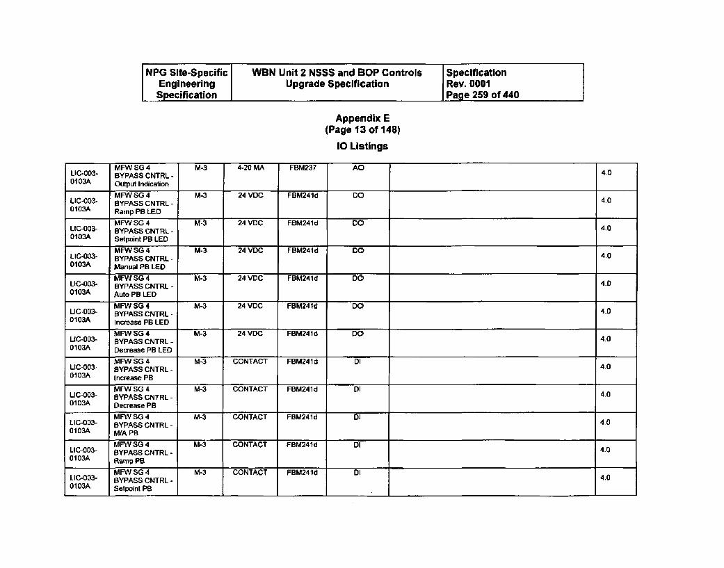
NPG Site-Specific WBN Unit 2 NSSS and BOP Controls SpecificationEngineering Upgrade Specification Rev. 0001Specification Page 259 of 440
Appemdix E(Page 13 of 148)
10 Listings
MFW SG 4 M-3 4-20 MA FBM237 AOLIC-003- BYPASS CNTRL - 4.00103A Output Indication
MFW SG 4 M-3 24 VD FBM241d DOLIC-COS- BYPASS CNTRL - 4.00103A Ramp PB LED
MFW SG 4 M-3 24 VDC FBM241d DOLIC-003- BYPASS CNTRL - 4.00103A Setpoint PB LED
MFW SG 4 M-3 24 VDC FBM241d DOLIC-003- BYPASS CNTRL - 400103A Manual PB LED
MFW SG 4 M-3 24 VDC FBM241d DOLIC-003- BYPASS CNTRL - 400103A Auto PB LED
MFWSG4 M-3 24 VDC FBM241d DOLIC-003- BYPASS CNTRL - 4.00103A Increase PB LED
MFW SG 4 M-3 24 VDC FBM241d DO4LIC-003- BYPASS CNTRL - 4.00103A Decrease PB LED
MFW SG 4 M-3 CONTACT FBM241 d DILIC-003- BYPASS CNTRL - 4.00103A Increase PB
MFW SG 4 M-3 CONTACT FBM241d DILIC-003- BYPASS CNTRL - 4.00103A Decrease PB
MFW SG 4 M-3 CONTACT FBM241d DI iLIC-003- BYPASS CNTRL - 4.00103A MIA PB
MFW SG 4 M-3 CONTACT FBM241d DILIC-003- BYPASS CNTRL - 4.00103A Ramp PB
MFWSG 4 M-3 CONTACT FBM24Id DILIC-003- BYPASS CNTRL - 4.00103A Setpoint PB
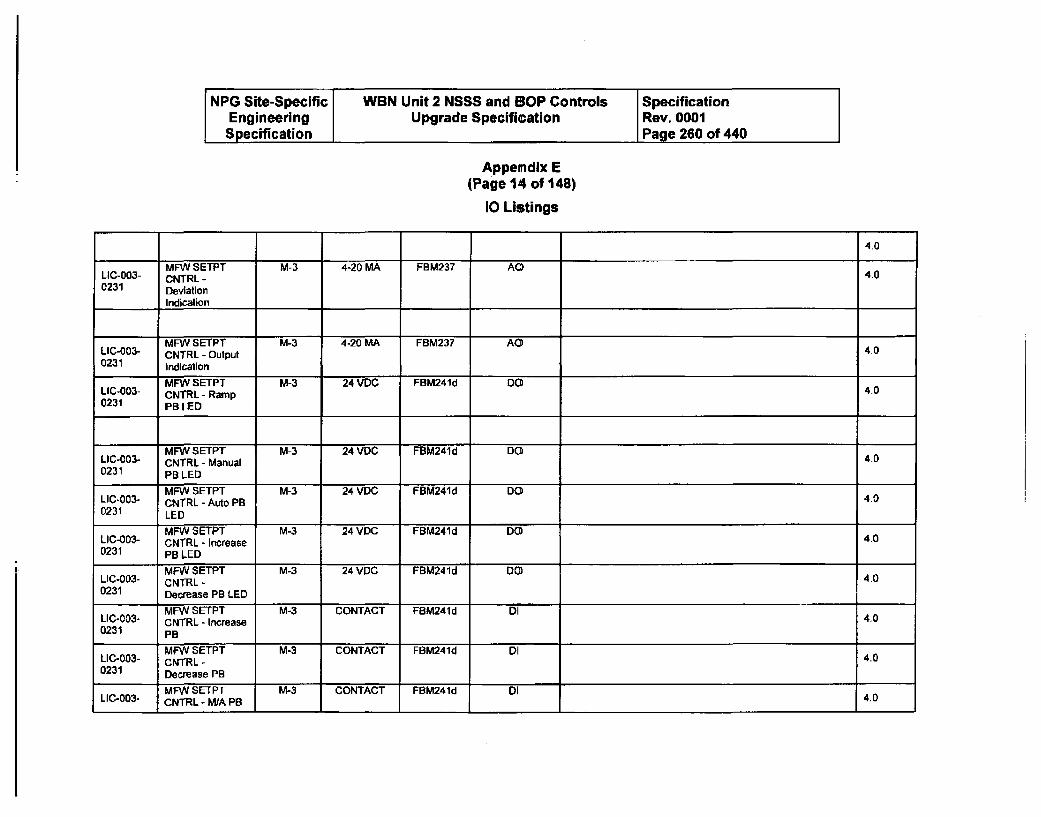
NPG Site-Specific WBN Unit 2 NSSS and BOP Controls SpecificationEngineering Upgrade Specification Rev. 0001Specification Page 260 of 440
Appendix E(Page 14 of 148)
10 Listings
4.0
MFVV SETPT M-3 4-20 MA FBM237 AOLIC-003- CNTRL - 4.00231 Deviation
Indication
MFA SETPT M-3 4-20 MA FBM237 AOLIC-003- CNTRL - Output 4.00231 Indication
MFW SETPT M-3 24 VDC FBM241d DOLIC-003- CNTRL- Ramp 4.00231 PRIBED
MFW SETPT M-3 24 V0C FBM241d DOLIC-003- CNTRL - Manual 4.00231 PB LED
MFA SETPT M-3 24 VDC FBM241d DOLIC-003- CNTRL - Auto PB 4.00231 LED
MAN SETPT M-3 24 VDC FBM241d DOLIC-003- CNTRL - Increase 4.00231 PB LED
MFA SETPT M-3 24 VDC FBM241d Do)LIC-003- CNTRL - 4.00231 Decrease PB LED
MFW SETPT M-3 CONTACT FBM241d DILIC-003- CNTRL - Increase 4.00231 PB
MFW SETPT M-3 CONTACT FBM241d DILIC-003- CNTRL - 4.00231 Decrease PB
MFW SETPT M-3 CONTACT FBM241d DI110-003- CNTRL - M/A PB 4.0
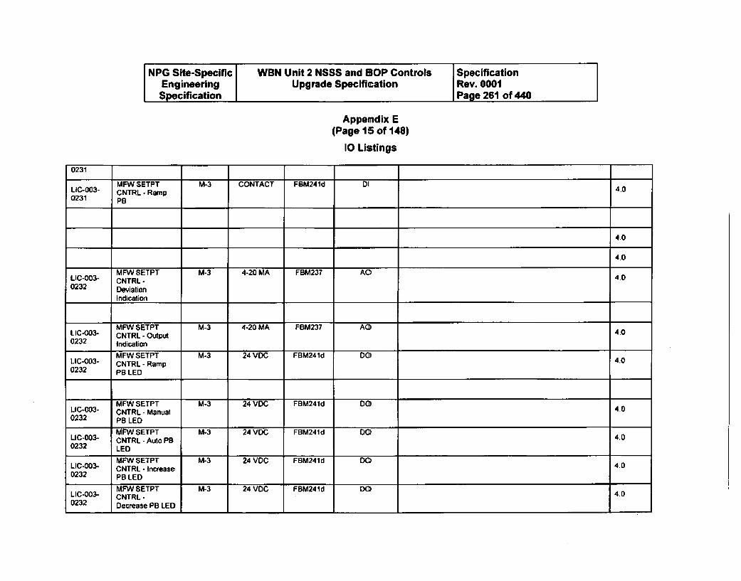
NPG Site-Specific WBN Unit 2 NSSS and BOP Controls SpecificationEngineering Upgrade Specification Rev. 0001Specification Page 261 of 440
Appendix E(Page 15 of 148)
10 Listings
0231
LEC-003- MFW SETPT M-3 CONTACT FBM241d DI 4.0CNTRL - Ramp0231 PB
40
4.0
MFW SETPT M-3 4-20 MA FBM237 AO 4.0LIC-003- CNTRL -
0232 Deviation
Indication
MFW SETPT M-3 4-20 MA F8M237 AOLIC-003- CNTRL - Output 400232 Indication
MFW SETPT M-3 24 VDC FBM241d DOLIC-003- CNTRL - Ramp 400232 PB LED
MFW SETPT M-3 24 VDC FBM241d DO4LIC-003- CNTRL - Manual 4.00232 PB LED
MFW SETPT M-3 24 VDC FBM241d DOLIC-003- CNTRL - Auto PB 4.00232 LED
MFW SETPT M-3 24 VDC FBM241d DO 4.0LI - 0 - C N T R L - In cre a s e4 .0232 PB LED
MFW SETPT M-3 24 VDC FBM241d DOLIC-003- CNTRL-0232 Decrease PB LED
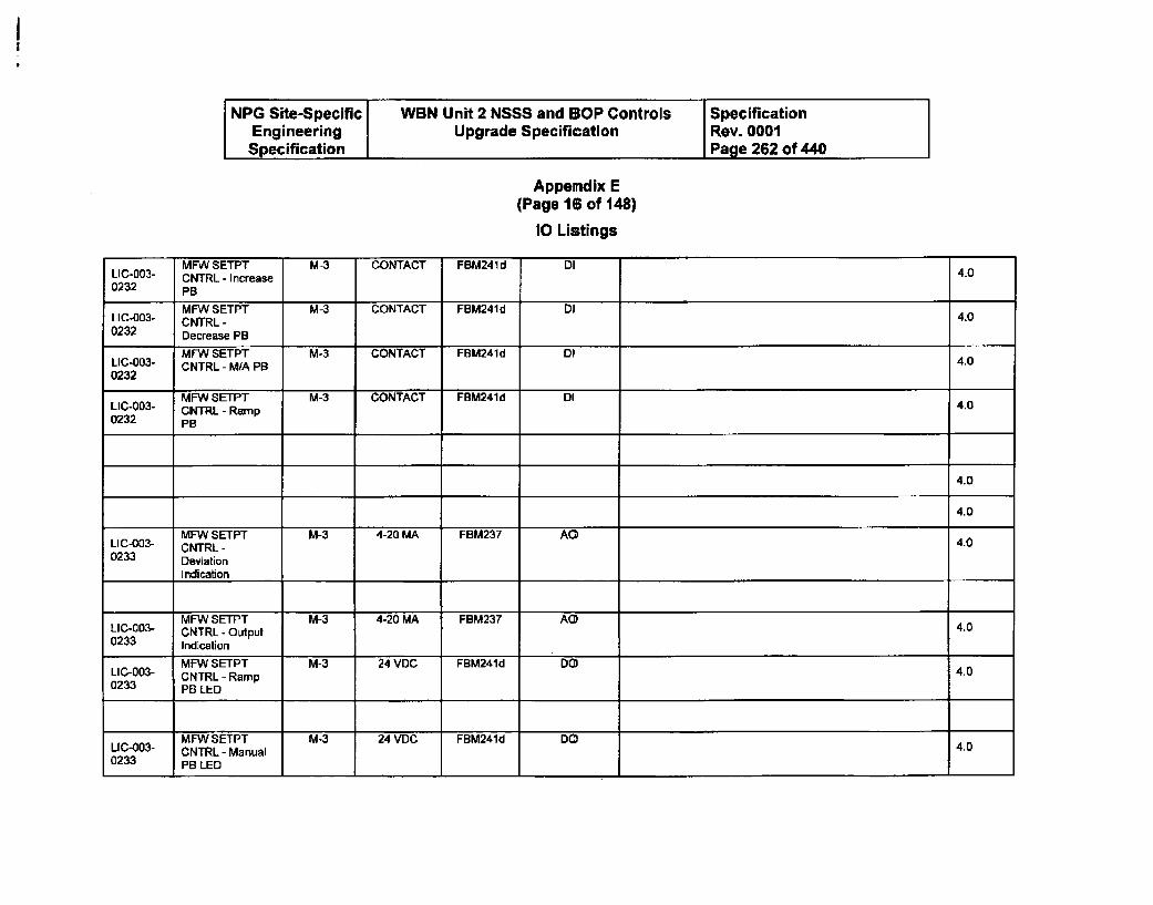
NPG Site-Specific WBN Unit 2 NSSS and BOP Controls SpecificationEngineering Upgrade Specification Rev. 0001Specification Page 262 of 440
Appendix E(Page 16 of 148)
10 Listings
MFW SETPT M-3 CONTACT FBM241 d DILIC-003- CNTRL - Increase 4.00232 PB
MFW SETPT M-3 CONTACT FBM241d DILIC-003- CNTRL - 4.00232 Decrease PB
MFW SETPT M-3 CONTACT FBM241d DILIC-003- CNTRL - MIA PB 4.00232
MFW SETPT M-3 CONTACT FBM241d DILIC-003- CNTRL - Ramp 4.00232 PB
4.0
4.0
MFW SETPT M-3 4-20 MA FBM237 AOLIC-003- CNTRL - 400233 Deviation
Indication
MFW SETPT M-3 4-20 MA FBM237 AOLICCOS3- CNTRL - Output 4.00233 Indication
L MFW SETPT M-3 24 VDC FBM241d DO 4.0LIC-003- CNTRL - Ramp0233 PB LED
MFW SETPT M-3 24 VDC FBM241d DCOUC-003- CNTRL - Manual 4.00233 PB LED
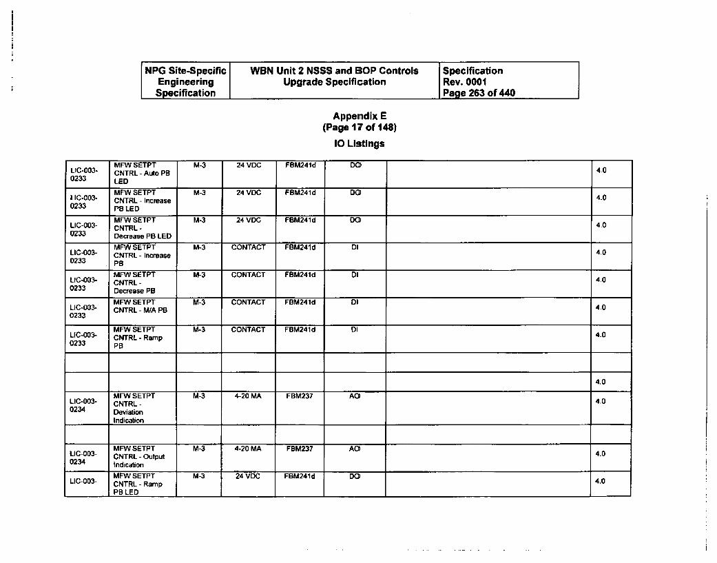
NPG Site-Specific WBN Unit 2 NSSS and BOP Controls SpecificationEngineering Upgrade Specification Rev. 0001Specification Page 263 of 440
Appendix E(Page 17 of 148)
10 Listings
MFW SETPT M-3 24 VDC FBM241d DOLIC-003- CNTRL - Auto PB 4.00233 LED
LIC-003- MFW SETPT M-3 24 VDC FBM241d DO toCNTRL - Increase0233 PB LED
MFW SETPT M-3 24 VDC FBM241d D00LIC-003- CNTRL - 4.00233 Decrease PB LED
MFW SETPT M-3 CONTACT FBM241d DILIC-003- CNTRL - Increase to0233 PB
MFW SETPT M-3 CONTACT FBM241d DILFC-003- CNTRL - to0233 Decrease PB
MFW SETPT M-3 CONTACT FBM241d DI 4.0LIC-003- CNTRL - MIA PB0233
MFW SETPT M-3 CONTACT FBM241d 1ILIC-003- CNTRL - Ramp 4.00233 PB
4.0
MFW SETPT M-3 4-20 MA FBM237 AO4LIC-003- CNTRL - 4.00234 Deviation
Indication
MFW SETPT M-3 4-20 MA FBM237 AO4LIC-003- CNTRL - Output 4.00234 Indication
MFW SETPT M-3 24 VDC FBM241d DO
LIC-003- CNTRL - Ramp 4.0
PB LED
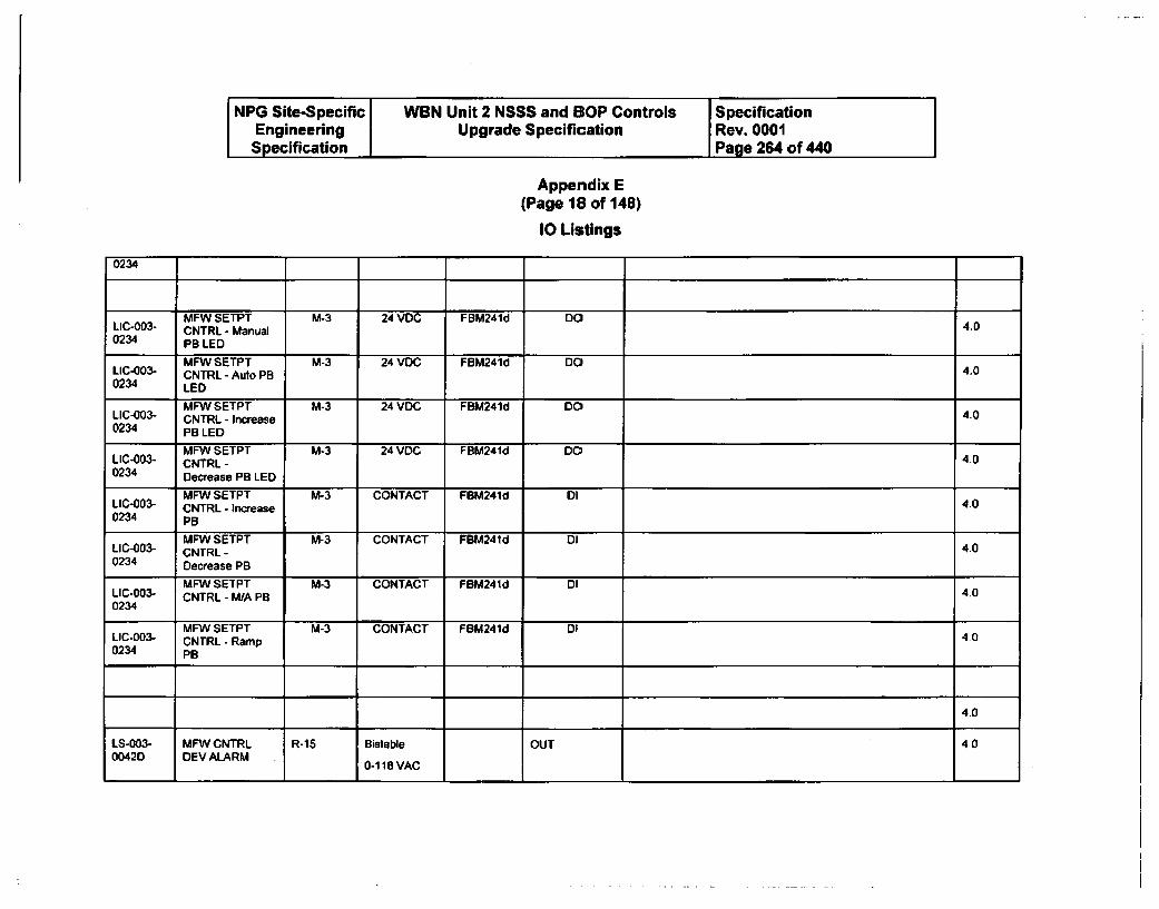
NPG Site-Specific WBN Unit 2 NSSS and BOP Controls SpecificationEngineering Upgrade Specification Rev. 0001Specification Page 264 of 440
Appendix E(Page 18 of 148)
10 Listings
0234
MFW SETPT M-3 24 VDC FBM241d DOLIC-003- CNTRL - Manual 4.00234 PB LED
MFW SETPT M-3 24 VDC FBM241d DOLIC-003- CNTRL - Auto PB 4.00234 LED
MFW SETPT M-3 24 VDC FBM241d DOLIC-003- CNTRL - Increase 4.00234 PB LED
MFW SETPT M-3 24 VDC FBM241d DOLIC-003- CNTRL - 4.00234 Decrease PB LED
MFW SETPT M-3 CONTACT FBM241d DILIC-003- CNTRL - Increase 4.00234 PB
MFW SETPT M-3 CONTACT FBM241d DILIC-003- CNTRL - 4.00234 Decrease PB
MFW SETPT M-3 CONTACT FBM241d DILIC-003- CNTRL - M/A PB 4.00234
MFW SETPT M-3 CONTACT FBM241d DILIC-003- CNTRL - Ramp 4.00234 PB
4.0
LS-003- MFW CNTRL R-15 Bistable OUT 400042D DEV ALARM 0-11VAC
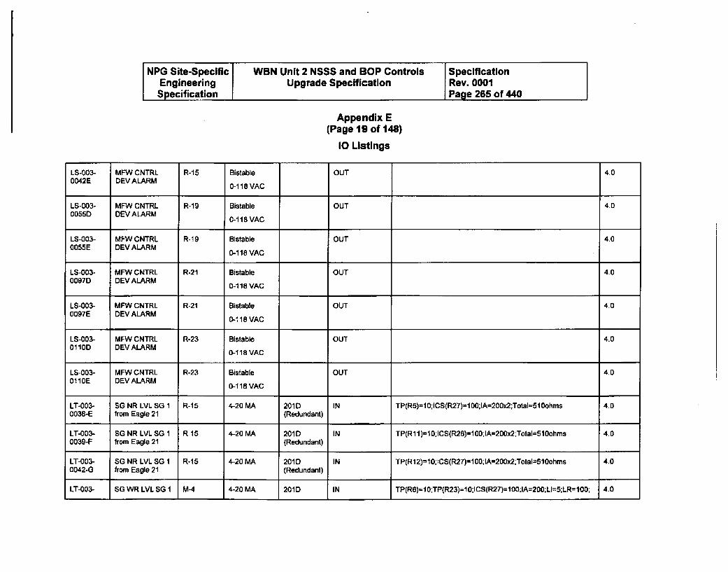
NPG Site-Specific WBN Unit 2 NSSS and BOP Controls SpecificationEngineering Upgrade Specification Rev. 0001Specification Page 265 of 440
Appendix E(Page 19 of 148)
10 Listings
LS-003- MFW CNTRL R-15 Bistable OUT 4.00042E DEV ALARM 0-118BVAC
LS-003- MFW CNTRL R-19 Bistable OUT 4.00055D DEV ALARM 0-118VAC
LS-003- MFW CNTRL R-19 Bistable OUT 4.00055E DEV ALARM 0-118 VAC
LS-003- MFW CNTRL R-21 Bistable OUT 400097D DEV ALARM 0-1 18 VAC
LS-003- MFW CNTRL R-21 Bistable OUT 4.00097E DEV ALARM 0-1 18 VAC
LS-003- MFW CNTRL R-23 Bistable OUT 4.00110D DEV ALARM 0-118 VAC
LS-003- MFW CNTRL R-23 Bistab[e OUT 4.00110E DEV ALARM 0-418 VAC
LT-003- SG NR LVL SG 1 R-15 4-20 MA 201D IN TP(R5)=10;ICS(R27)=100;IA=200x2;Total=510ohms 4.00038-E from Eagle 21 (Redundant)
LT-003- SG NR LVL SG 1 R-15 4-20 MA 201D IN TP(R11)=10;ICS(R26)=100;IA=200x2;TotaI=510ohms 4.00039-F from Eagle 21 (Redundant)
LT-003- SG NR LVL SG 1 R-15 4-20 MA 201D IN TP(R12)n-10; CS(R27)=100;IA=200x2;Total=50ohms 4.00042-G from Eagle 21 (Redundant)
LT-003- SG WR LVL SG I M-4 4-20 MA 201D IN TP(R6)=10:TP(R23)=10:ICS(R27)=1I0;IA=200;LI=5;LR=100; 4.0
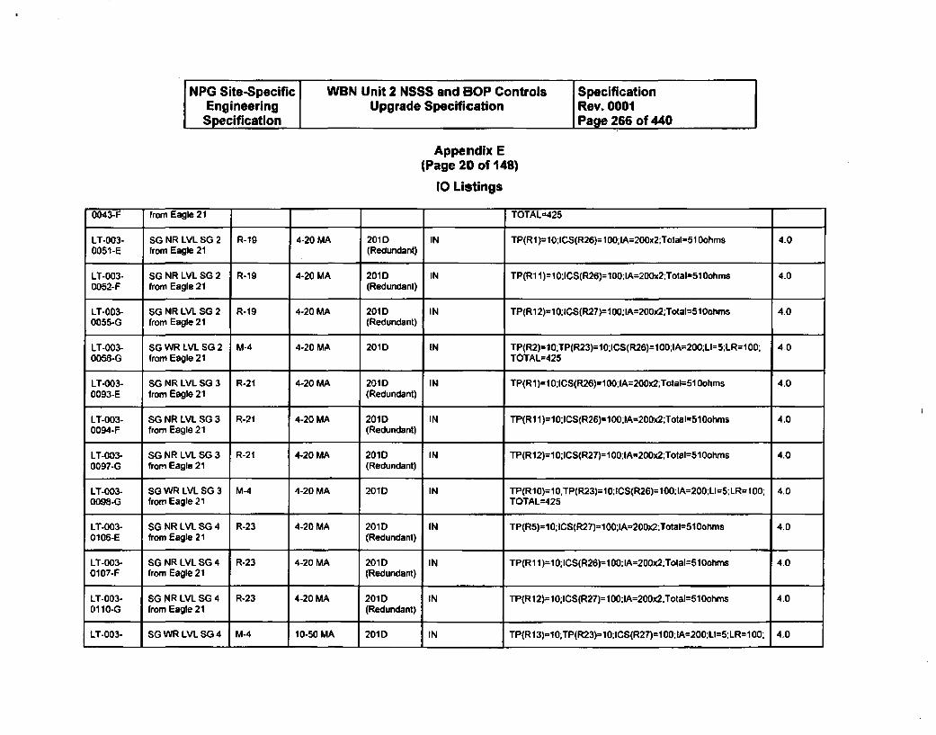
NPG Site-Specific WBN Unit 2 NSSS and BOP Controls SpecificationEngineering Upgrade Specification Rev. 0001Specification I Page 266 of 440
Appendix E(Page 20 of 148)
10 Listings
0043-F from Eagle 21 TOTAL=425
LT-003- SG NR LVL SG 2 R-19 4-20 MA 201 D IN TP(RI)-10;ICS(R26)=100;IA=200x2;Total=51 Oohrns 4.00051-E from Eagle 21 (Redundant)
LT-003- SG NR LVL SG 2 R-19 4-20 MA 201D IN TP(R1 1)=10:lCS(R26)=100;IA=200x2;Total=510ohma 4.00052-F from Eagle 21 (Redundant)
LT-003- SG NR LVIL SG 2 R-19 4-20 MA 201D IN TP(R12)=10:ICS(R27)=100:IA=200r2;Total=510ohms 4.00055-G from Eagle 21 (Redundant)
LT-003- SG WR LVL SG2 M-4 4-20 MA 201D IN TP(R2)=IO;TP(R23)=10;ICS(R26)=100;IA=200;LI=5;LR=100; 4.00056-G from Eagle 21 TOTAL=425
LT-003- SG NR LVL SG 3 R-21 4-20 MA 201D IN TP(R1)=10;ICS(R26)=100:IA=200x2;Tota=510Oohms 4.00093-E from Eagle 21 (Redundant)
LT-003- SG NR LVL SG 3 R-21 4-20 MA 201D IN TP(R11)=10;ICS(R26)=100:IA=200x2;Total-510ohms 4.00094-F from Eagle 21 (Redundant)
LT-003- SG NR LVL SG 3 R-21 4-20 MA 201D IN TP(R12)=10;ICS(R27)=100;IA=200x2;Total=510ohms 4.00097-G from Eagle 21 (Redundant)
LT-003- SG WR LVIL SG 3 M-4 4-20 MA 201D IN TP(R10)=1O.TP(R23)=10;ICS(R26)=100IlA=200;LI=5;LR=100; 4.00098-G from Eagle 21 TOTAL=425
LT-003- SG NR LVL SG 4 R-23 4-20 MA 201D IN TP(R5)=10;ICS(R27)=100;IA=200x2;Total=510ohms 4.00106-E from Eagle 21 (Redundant)
LT-003- SG NR LVL SG 4 R-23 4-20 MA 201D IN TP(R11)=10;ICS(R26)=100;IA=200x2;Total=51Oohms 4.00107-F from Eagle 21 (Redundant)
LT-003- SG NR LVIL SG 4 R-23 4-20 MA 201D IN TP(R12)=10;ICS(R27)=100-IA=200x2;Total=510ohms 4.0
0110-G from Eagle 21 (Redundant)
LT-003- SG WR LVL SG4 M-4 10-50 MA 201D IN TP(R13)-10;TP(R23)=10:ICS(R27)=100;IA=200:.LI=5;LR=100: 4.0
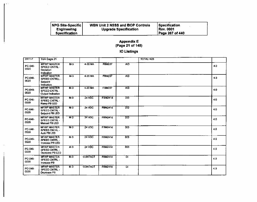
NPG Site-Specific WBN Unit 2 NSSS and BOP Controls SpecificationEngineering Upgrade Specification Rev. 0001Specification Page 267 of 440
Appemdix E(Page 21 of 148)
10 Listings
0111-F from Eagle 21 TOTAL-425
MFWP MASTER M-3 4-20 MA FBM237 AC4PC-046- SPEED CNTRL - 4.00020 Deviation
IndicationMFWP MASTER M-3 4-20 MA FBM237 AC)
PC-046- SPEED CNTRLL - 4_00020 Setpoint
Indication A0MFWP MASTER M-3 4-20 MA FBM237 A4)
PC-046- SPEED CNTRL - 4.00020 Output Indication
MFWP MASTER M-3 24 VOC FBM241d DOPC-046- SPEED CNTRL - 4.00020 Ramp PB LED
MFWP MASTER M-3 24 VDC FBM241d DOPC-046- SPEED CNTRL - 4.00020 Setpoint PB LED
MFWP MASTER M-3 24 VDC FBM241d DOPC-046- SPEED CNTRL - 4.00020 Manual PB LED
MFWP MASTER M-3 24 VDC FBM241d DOPC-046- SPEED CNTRL - 4.00020 Auto PB LED
MFWP MASTER M-3 24 VDC FBM241d DOPC-046- SPEED CNTRL - 4.00020 Increase PB LED
MFWP MASTER M-3 24 VDC FBM241d DCPC-046- SPEED CNTRL - 4.00020 Decrease PB LED
MFWP MASTER M-3 CONTACT FBM241d DIPC-046- SPEED CNTRL - 4.00020 Increase PB
MFWP MASTER M-3 CONTACT FBM241J DIP0-046- SPEED CNTRL - 4.00020 Decrease PB
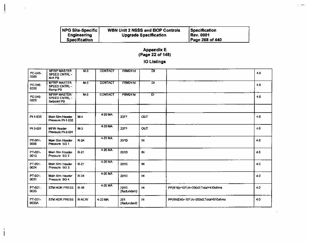
NPG Site-Specific WBN Unit 2 NSSS and BOP Controls SpecificationEngineering Upgrade Specification Rev. 0001Specification Page 268 of 440
Appendix E(Page 22 of 148)
10 Listings
MFWP MASTER M-3 CONTACT FBM241d DIPC-046- SPEED CNTRL - 4.00020 M/A PB
MFWP MASTER M-3 CONTACT FBM241d DIIPC-046- SPEED CNTRL - 4.00020 Ramp PB
MFWP MASTER M-3 CONTACT FBM241d DIPC-046- SPEED CNTRL - 4.00020 Setpoint Pa
P1-1-033 Main Stm Header M-4 4-20 MA OUT 40Pressure P1-1-033
4-20 MAPI-3-001 MFW Header M-3 237? OUT 4.0
Pressure PI-3-001
4-20 MA ...
PT-001- Main Stm Header R-24 201D IN 4-00006 Pressure SG 1
4-20 MAPT-001- Main Stm Header R-21 201D IN 4.00013 Pressure SG 2
4-20 MAPT-0OW- Main Stm Header R-21 201D IN 4.00024 Pressure SG 3
4-20 MAPT-001- Main Stm Header R-24 201D IN 4.00031 Pressure SG 4
4-20 MAPT-001- STM HDR PRESS R-16 201D IN PP(R16)=10?;IA=200x2:Total=410ohms 4.00033 (Redundant)
PT-001- STM HDR PRESS R-NEW 4-20 MA 201 IN PP(RNEW)=10?;IA=250x2:Total=510ohms 4.00033A (Redundant)
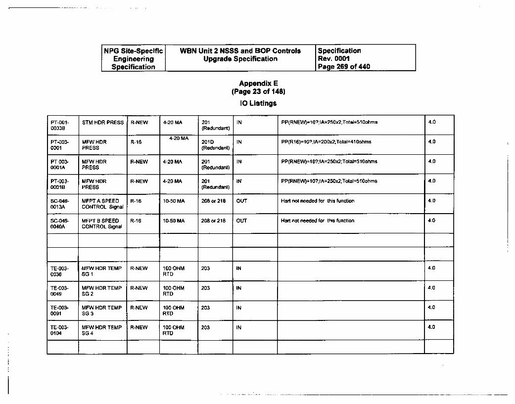
NPG Site-Specific WBN Unit 2 NSSS and SOP Controls SpecificationEngineering Upgrade Specification Rev. 0001Specification Page 269 of 440
Appendix E(Page 23 of 148)
10 Listings
PT-001- STM HDR PRESS R-NEW 4-20 MA 201 IN PP(RNEW)=10?:IA=250x2;Total=510ohms 4.00033B (Redundant)
4-20 MAPT-003- MFW HDR R-16 201D IN PP(R16)=10"R:IA=200x2;TotaI-410ohms 4.00001 PRESS (Redundant)
PT-003- MFW HDR R-NEW 4-20 MA 201 IN PP(RNEW)=t 0?;:A=250x2;Total=510ohms 4.00001A PRESS (Redundant)
PT-003- MFW HDR R-NEW 4-20 MA 201 IN PP(RNEW)=10?;IA=250x2;Total=510ohms 4.00001B PRESS (Redundant)
SC-046- MFPTASPEED R-16 10-50 MA 208 or 218 OUT Hart not needed for this function 4.00013A CONTROL Signal
SC-046- MFPT B SPEED R-16 10-50 MA 208 or 218 OUT Hart not needed for this function 4.00040A CONTROL Signal
TE-003- MFW HDR TEMP R-NEW 100 OHM 203 IN 4.00036 SG 1 RTD
TE-003- MFW HDR TEMP R-NEW 100 OHM 203 IN 4.00049 SG 2 RTD
TE-003- MFW HDR TEMP R-NEW 100 OHM 203 IN 4.00091 SG3 RTD
TE-003- MFW HDR TEMP R-NEW 100 OHM 203 IN 4.00104 SG4 RTD
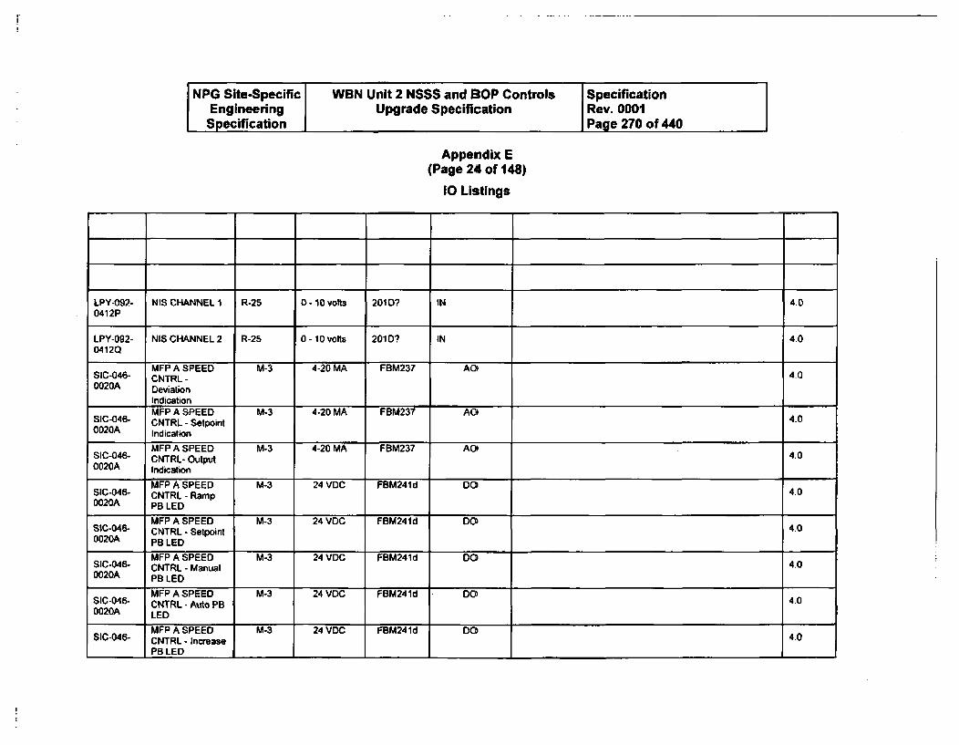
NPG Site-Specific WBN Unit 2 NSSS and BOP Controls SpecificationEngineering Upgrade Specification Rev. 0001Specification Page 270 of 440
Appendix E(Page 24 of 148)
10 Listings
LPY-092- NIS CHANNEL 1 R-25 0- 10 volts 201D? IN 4.00412P
LPY-092- NIS CHANNEL 2 R-25 0 - 10 volts 201 D? IN 4.00412Q
MFP A SPEED M-3 4-20 MA FBM237 AOSIC-046- CNTRL - 4-00020A Deviation
Indication
MFP A SPEED M-3 4-20 MA FBM237 AOSIC*046- CNTRL - Setpoint 400020A Indication
MFP A SPEED M-3 4-20 MA FBM237 AOSIC-046- CNTRL- Output 4.00020A Indication
MFP A SPEED M-3 24 VDC FBM241d DOSIC-046- CNTRL - Ramp 400020A PB LED
MFP A SPEED M-3 24 VDC FBM241d DOSIC-046- CNTRL - Setpoint 400020A PB LED
MFP A SPEED M-3 24 VDC FBM241d DOSIC-046- CNTRL - Manual 4.00020A PB LED
MFP A SPEED M-3 24 VOC FBM241d DOSIC-046- CNTRL - Auto PB 4.00020A LED
MFP A SPEED M-3 24 VDC FBM241d DOSIC-046- CNTRL - Increase 4.0
PB LED I
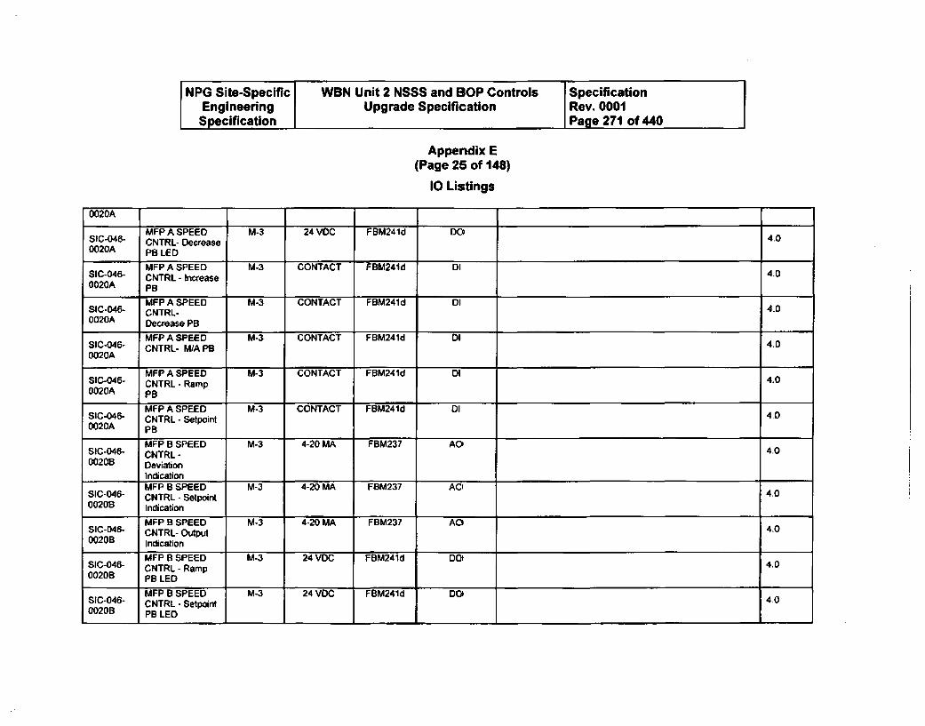
NPG Site-Specific WBN Unit 2 NSSS and BOP Controls SpecificationEngineering Upgrade Specification 1 Rev. 0001Specification I Page 271 of 440
Appendix E(Page 25 of 148)
I Listings
0020A
MFP A SPEED M-3 24 VOC FBM241d DO 4.0SIC-046- CNTRL- Decrease0020A PB LED
MFP A SPEED M-3 CONTACT FBM241d DI 4.0SIC-046- CNTRL - Increase0020A PB
MFP A SPEED M-3 CONTACT FBM241d DISIC-046- CNTRL- 400020A Decrease PB
MFP A SPEED M-3 CONTACT FBM241d DISIC-046- CNTRL- W/A PB 400020A
MFP A SPEED M-3 CONTACT FBM241d 04SIC-046- CNTRL - Ramp 4.00020A PB
MFP A SPEED M-3 CONTACT FBM241d DISIC-046- CNTRL - Setpoint 4.00020A PB
MFP B SPEED M-3 4-20 MA FBM237 AO,SIC-046- CNTRL - 4.00020B Deviation
IndicationMFP 8 SPEED M-3 4-20 MA FBM237 AC0
SIC-046- CHTRL - Setpoint 4.00020B Indication
MFP B SPEED M-3 4-20 MA FBM237 AO4S1C-046- CNTRL- Output 4.00020B Indication
MFP B SPEED M-3 24 VDC FBM241d DO4SIC-046- CNTRL - Ramp 4.000206 PB LED
MFP B SPEED M-3 24 VDC FBM241d DOIS1C-046- CNTRL - Setpoinl 4.000206 PB LED

NPG Site-Specific WBN Unit 2 NSSS and BOP Controls SpecificationEngineering Upgrade Specification Rev. 0001Specification Page 272 of 440
Appendix E(Page 26 of 148)
10 Listings
MFP B SPEED M-3 24 VDC FBM241d DOSIC-046- CNTRL - Manual 4.00020B PB LED
MFP B SPEED M-3 24 VDC FBM241d DO4SIC-046- CNTRL - Auto PB 4.00020B LED
MFP B SPEED M-3 24 VDC FBM241d DO 4.0SIC-046- CNTRL - Increase0020B PB LED
MFP B SPEED M-3 24 VDC FBM241d DOSICo046- CNTRL- Decrease 4.00020B PB LED
MFP B SPEED M-3 CONTACT FBM241d DISIC-046- CNTRL - Increase 4.00020B PB
MFP B SPEED M-3 CONTACT FBM241d DISIC-046- CNTRL- 4.00020B Decrease PB
MFP B SPEED M-3 CONTACT FBM241d DISIC-046- CNTRL- M/A PB 4.00020B
MFP B SPEED M-3 CONTACT FBM241d DISIC-046- CNTRL - Ramp 4.0002DB PB
MFP B SPEED M-3 CONTACT FBM241d DISIC-046- CNTRL - Setpoint 4.00020B PB
M-3 4-20 MA 4.0PT-46-12 MFPT A BRG OIL IN
PRESSM-3 4-20 MA 4.0
PT-46-17 MFPTA BRG OIL IN
PRESSM-3 4-20 MA 4.0
PT-46-39 MFPT B BRG OIL IN
PRESS
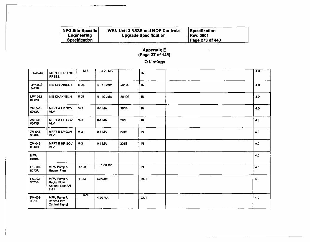
NPG Site-Specific WBN Unit 2 NSSS and BOP Controls SpecificationEngineering Upgrade Specification Rev. 0001
Specification Page 273 of 440
Appendix E(Page 27 of 148)
10 Listings
M-3 4-20 MA 4.0PT-46-45 MFPT B BRG OIL IN
PRESS
LPY-092- NIS CHANNEL 3 R-25 0 - 10 volts 201D? IN 4.0
0412R
LPY-092- NIS CHANNEL 4 R-25 0 - 10 volts 201D? IN 4.00412S
ZM-046- MFPT A LP GOV M-3 0-1 MA 201B IN 4.00013A VLV
ZM-046- MFPT A HP GOV M-3 0-1 MA 201B IN 4.00013B VLV
ZM-046- MFPT B LP GOV M-3 0-1 MA 2018 IN 4.00040A VLV
ZM-046- MFPT B HP GOV M-3 0-1 MA 201B IN 4.00040B VLV
MFW 4.0Recirc
4-20 MAFT-003- MFW Pump A R-123 IN 4.00070A Header Flow
FS-003- MFW Pump A R-123 Contact OUT 4.00070B Recirc Flow
Annunc iator AN2-11
M-3FM-003- MFW Pump A 4-20 MA OUT 4.00070E Recire Flow
Control Signal
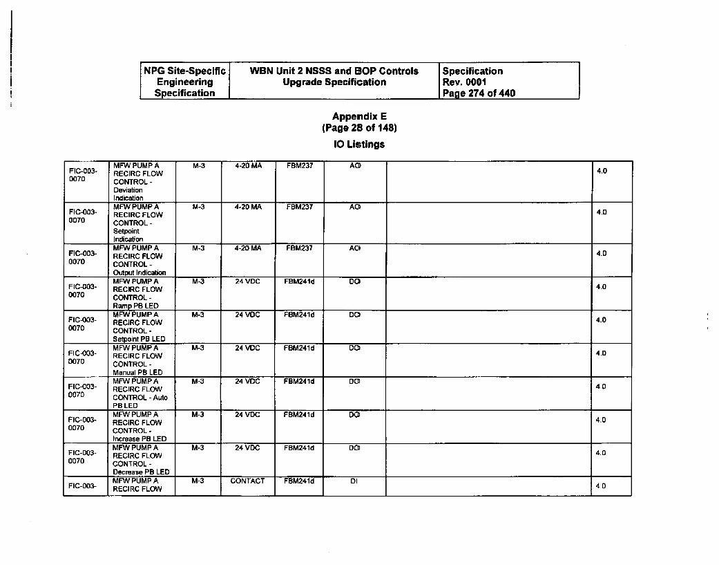
NPG Site-Specific WBN Unit 2 NSSS and BOP Controls SpecificationEngineering Upgrade Specification Rev. 0001Specification Page 274 of 440
Appendix E(Page 28 of 148)
I Listings
MFW PUMP A M-3 4-20 MA FBM237 AOFIC-003- RECIRC FLOW 4.00070 CONTROL -
DeviationIndicationMFW PUMP A M-3 4-20 MA FBM237 AO
FIC-003- RECIRC FLOW 4.00070 CONTROL -
SetpointIndicationMFW PUMP A M-3 4-20 MA FBM237 AO4
FIC-003- RECIRC FLOW 4.00070 CONTROL -
Output IndicationMFW PUMP A M-3 24 VDC FBM241d DO
FIC-003- RECIRC FLOW 4.00070 CONTROL -
Ramp PB LEDMFW PUMP A M-3 24 VDC FBM241d DO
FIC-003- RECIRC FLOW 4-00070 CONTROL -
I Setpoint PB LEDMFW PUMP A M-3 24 VDC FBM241 d DO
FIC-003- RECIRC FLOW 4.00070 CONTROL -
Manual PB LEDMFW PUMP A M-3 24 VDC FBM241d DO
FIC-003- RECIRC FLOW 4.00070 CONTROL - Auto
PB LEDMFW PUMP A M-3 24 VDC FBM241d DO
FIC-003- RECIRC FLOW 4.00070 CONTROL -
Increase PB LEDMFW PUMP A M-3 24 VDC FBM241d DO
FIC-003- RECIRC FLOW 4.00070 CONTROL-
Decrease PB LEDMFW PUMP A M-3 CONTACT FBM241d DI 4.0
FIC-003- RECIRC FLOW II0
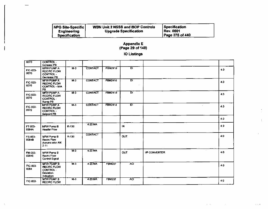
NPG Site-Specific WBN Unit 2 NSSS and BOP Controls SpecificationEngineering Upgrade Specification Rev. 0001Specification Page 275 of 440
Appendix E(Page 29 of 148)
10 Listings
0070 CONTROL-Increase PBMFW PUMP A M-3 CONTACT FBM241d DI 4.0
FIC-003- RECIRC FLOW40070 CONTROL -
Decrease PBMFW PUMP A M-3 CONTACT FBM24Id DI
FIC-003- RECIRC FLOW 400070 CONTROL - M/A
PBMFW PUMP A M-3 CONTACT FBM241d DI 40
FIC-003- RECIRC FLOW0070 CONTROL -
Ramp PBMFW` PUMP A M-3 CONTACT FBM241d 0I
FIC-003- RECIRC FLOW 400070 CONTROL-
Setpoint PB
4.0
FT-003- MFW Pump B R-130 4-20 MA IN 4.00084A Header Flow
FS-003- MFW Pump B R-130 CONTACT OUT 400084B Recirc Flow
Annunc iator AN2-11
M-3 4-20 MAFM-003- MFW Pump B OUT i/P CONVERTER 400084E Recirc Flow
Control Signal
MFW PUMP B M-3 4-20 MA FBM237 AOFIC-003- RECIRC FLOW 400084 CONTROL -
DeviationIndicationMFW PUMP B M-3 4-20 MA FBM237 AOC
FIC-003- RECIRC FLOW 4.0

NPG Site-Specific WBN Unit 2 NSSS and BOP Controls SpecificationEngineering Upgrade Specification Rev. 0001Specification Page 276 of 440
Appendix E(Page 30 of 148)
10 Listings
0084 CONTROL -
SetpointIndicationMFW PUMP B M-3 4-20 MA FBM237 AO4
FIC-003- RECIRC FLOW 4.00084 CONTROL-
Output IndicationMFW PUMP 8 M-3 24 VDC FBM241d DO 4.0
FIC-003- RECIRC FLOW0084 CONTROL-
Ramp PB LEDMFW PUMP B M-3 24 VDC FBM241d D04
FIC-003- RECIRC FLOW 4.00084 CONTROL -
I Selpoint PB LEDMFW PUMP B M-3 24 VDC FBM241d DO' 4.0
FIC-003- RECIRC FLOW0084 CONTROL -
Manual PB LEDMFW PUMP B M-3 24 VDC FBM241d DC0 4.0
FIC-003- RECIRC FLOW0084 CONTROL - Auto
PB LEDMFW PUMP B M-3 24 VDC FBM241d D04
FIC-003- RECIRC FLOW 4.00084 CONTROL-
Increase PB LEDMFW PUMP B M-3 24 VOC FBM241d DO' 40
FIC-003- RECIRC FLOW0084 CONTROL-
I Decrease PB LED IMFW PUMP B M-3 CONTACT FBM241d DI
FIC-003- RECIRC FLOW 4.00084 CONTROL -
Increase PB1MFW PUMP B M-3 CONTACT FBM241d DI
FIC-003- RECIRC FLOW 400084 CONTROL -
I Decrease PB
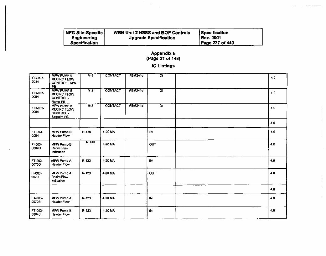
NPG Site-Specific WBN Unit 2 NSSS and BOP Controls SpecificationEngineering Upgrade Specification Rev. 0001Specification Page 277 of 440
Appendix E(Page 31 of 148)
10 Listings
MFW PUMP B M-3 CONTACT FBM241d DI 40FIC-003- RECIRC FLOW0084 CONTROL - WA
PBMFW PUMP B M-3 CONTACT FBM241d DI
FIC-003- RECIRC FLOW 400084 CONTROL -
I Ramp PB IMFW PUMP B M-3 CONTACT FBM241d DI
FIC-003- RECIRC FLOW 400084 CONTROL -
Selpoint PB
4.0
FT-003- MFW Pump B R-130 4-20 MA IN 4.00084 Header Flow
R-130FI-003- MFW Pump B 4-20 MA OUT 4.000840 Recirc Flow
Indication
FT-003- MFW Pump A R-1 23 4-20 MA IN 4.00070D Header Flow
FI-003- MFW Pump A R-123 4-20 MA OUT 4.00070 Recirc Flow
Indication
4.0
FT-003- MFW Pump A R-1 23 4-20 MA IN 4.00070B Header Flow
FT-003- MFW Pump B R-123 4-20 MA IN 4.00084B Header Flow
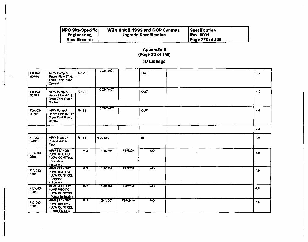
NPG Site-Specific WBN Unit 2 NSSS and SOP Controls SpecificationEngineering Upgrade Specification Rev. 0001Specification Page 278 of 440
Appendix E(Page 32 of 148)
10 Listings
FS-003- MFW Pump A R-1 23 CONTACT OU400070A Recirc Flow #7 Htr
Drain Tank PumpControl
CONTACTFS-003- MFW Pump A R-123 OUT 4.000700 Recirc Flow #7 Htr
Drain Tank PumpControl
FS-003- MFW Pump A R-123 CONTACT OUT 4.00070E Recirc Flow #7 Hit
Drain Tank PumpControl
4.0
FT-003- MFW Standby R-141 4-20 MA IN 4.00208B Pump Header
Flow
MFW STANDBY M-3 4-20 MA FBM237 AOFIC-003- PUMP RECIRC 400208 FLOW CONTROL
- DeviationIndicationMFW STANDBY M-3 4-20 MA FBM237 AO
FIC-003- PUMP RECIRC 4.00208 FLOW CONTROL
- SetpointIndicationMFW STANDBY M-3 4-20 MA FBM237 AO4
FIC-003- PUMP RECIRC 4.00208 FLOW CONTROL
- Output IndicationMFW STANDBY M-3 24 VDC FBM241d DO
FIC-003- PUMP RECIRC 4.00208 FLOW CONTROL
- Ramp PB LED
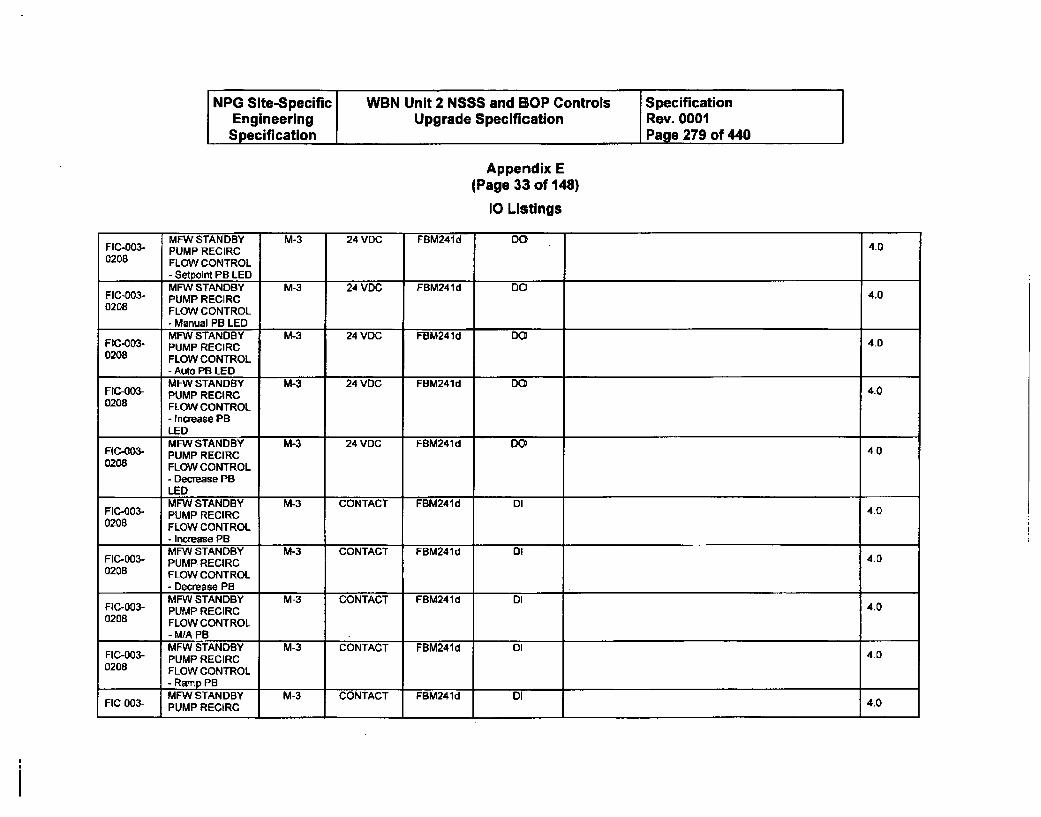
NPG Site-Specific WBN Unit 2 NSSS and BOP Controls SpecificationEngineering Upgrade Specification Rev. 0001Specification Page 279 of 440
Appendix E(Page 33 of 148)
10 Listings
MFW STANDBY M-3 24 VDC FBM241d DOFIC-003- PUMP RECIRC 4.00208 FLOW CONTROL
- Setpoint PB LEDMFW STANDBY M-3 24 VDC FBM241d DOFIC-003- PUMP RECIRC 4.0
0208 FLOW CONTROL
- Manual PB LEDMFW STANDBY M-3 24 VDC FBM241d DOFIC-003- PUMP RECIRC 4.0
0208 FLOW CONTROL
- Auto PB LEDMFW STANDBY M-3 24 VDC FBM241d DOFIC-003- PUMP RECIRC 4.0
0208 FLOW CONTROL
- Increase PBLEDMFW STANDBY M-3 24 VDC FBM241d DO
FIC.003- PUMP RECIRC 4.00208 FLOW CONTROL
- Decrease PBLEDMFWSTANDBY M-3 CONTACT FBM241d DI 4FIC-003- PUMP RECIRC 4.0
0208 FLOW CONTROL- Increase PBMFW STANDBY M-3 CONTACT FBM241d DIFIC-003- PUMP RECIRC 4.0
0208 FLOW CONTROL
- Decrease PB IMFW STANDBY M-3 CONTACT FBM241d D4FIC-003- PUMP RECIRC 4.0
0208 FLOW CONTROL- MIA PBMFW STANDBY M-3 CONTACT FBM241d DIFIC-003- PUMP RECIRC 40
0208 FLOW CONTROL
- Ramp PBMFW STANDBY M-3 CONTACT FBM241d DI
FIC-003- PUMP RECIRC 4.0
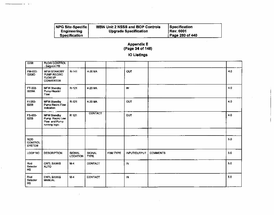
NPG Site-Specific WBN Unit 2 NSSS and BOP Controls SpecificationEngineering Upgrade Specification Rev. 0001Specification Page 280 of 440
Appendix E(Page 34 of 148)
10 Listings
0208 FLOW CONTROL- Setpoint PB
FM-003- MFW STANDBY R-141 4-20 MA OUT 4.00208D PUMP RECIRC
FLOW I/PCONVERTER
FT-003- MFW Standby R-121 4-20 MA IN 4.00208A Pump Header
Flow
FI-003- MFW Standby R-121 4-20 MA OUT 4.00208 Pump Recirc Flow
IndicationCONTACT,
FS-003- MFW Standby R-121 OUT 4.00208 Pump Recih Low
Flow and Pumprunning logic
ROD 5.0CONTROLSYSTEM
LOOP NO DESCRIPTION SIGNAL SIGNAL FBM TYPE INPUT/OUTPUT COMMENTS 5.0LOCATION TYPE
Rod CNTL BANKS M-4 CONTACT IN 5.0Selector AUTOHS
Rod CNTL BANKS M-4 CONTACT IN 5.0Selector MANUALHS
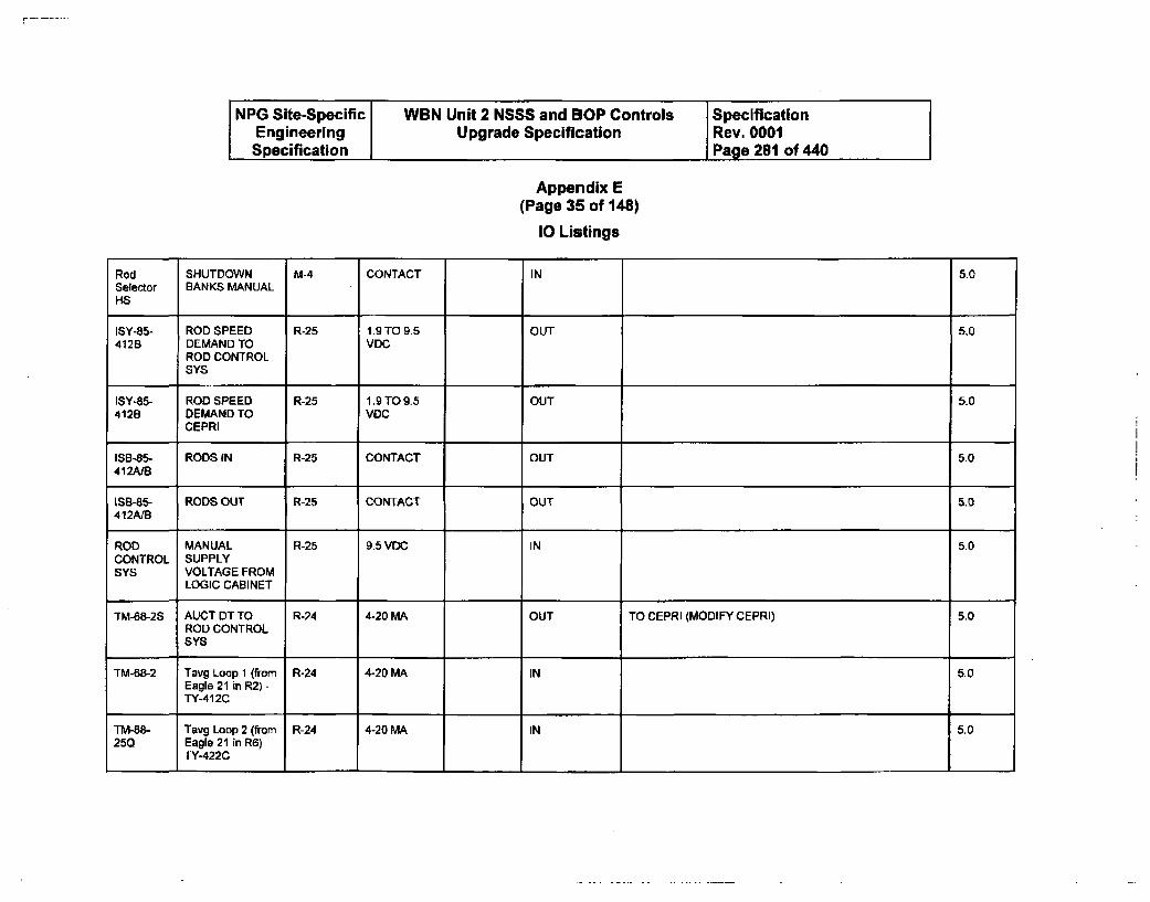
NPG Site-Specific WBN Unit 2 NSSS and BOP Controls SpecificationEngineering Upgrade Specification Rev. 0001Specification Page 281 of 440
Appendix E(Page 35 of 148)
10 Listings
Rod SHUTDOWN M-4 CONTACT IN 5.0Selector BANKS MANUALHS
ISY-85- ROD SPEED R-25 1.9 TO 9.5 OUT 5.0412B DEMAND TO VDC
ROD CONTROLSYS
ISY-85- ROD SPEED R-25 1.9 TO 9.5 OUT 5.04128 DEMAND TO VDC
CEPRI
IS3-85- RODS IN R-25 CONTACT OUT 5.0412A/J
ISB-85- RODS OUT R-25 CONTACT OUT 5.0412A1B
ROD MANUAL R-25 9.5 VDC IN 5.0CONTROL SUPPLYSYS VOLTAGE FROM
LOGIC CABINET
TM-88-2S AUCT DT TO R-24 4-20 MA OUT TO CEPRI (MODIFY CEPRI) 5.0ROD CONTROLSYS
TM-88-2 Tavg Loop 1 (from R-24 4-20 MA IN 5.0Eagle 21 in R2) -TY-412C
TM-68- Tavg Loop 2 (from R-24 4-20 MA IN 5.0250 Eagle 21 in R6)
TY-422C
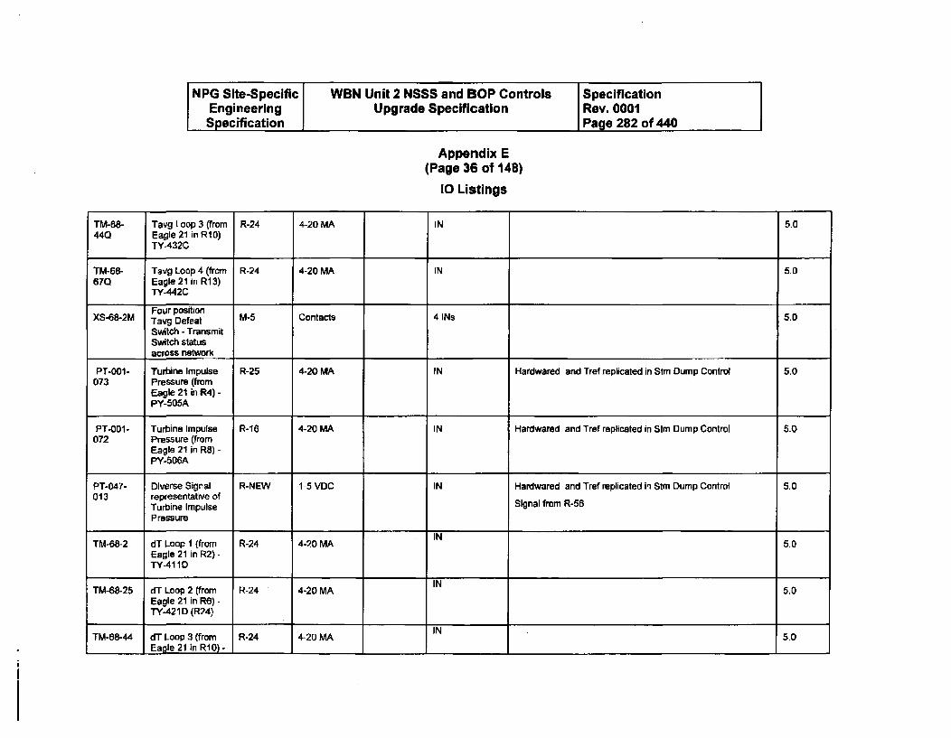
NPG Site-Specific WBN Unit 2 NSSS and BOP Controls SpecificationEngineering Upgrade Specification Rev. 0001
Specification Page 282 of 440
Appendix E(Page 36 of 148)
10 Listings
TM-68- Tavg Loop 3 (from R-24 4-20 MA IN 5.0440 Eagle 21 in RIO)
TY-432C
TM-68- Tavg Loop 4 (from R-24 4-20 MA IN 5.067Q Eagle 21 in R13)
TY-442CFour position
XS-68-2M Tavg Defeat M-5 Contacts 4 INs 5.0
Switch - TransmitSwitch statusacross network
PT-0O1- Turbine Impulse R-25 4-20 MA IN Hardwared and Tref replicated in Stm Dump Control 5.0073 Pressure (from
Eagle 21 in R4) -PY-505A
PT-0D1- Turbine Impulse R-16 4-20 MA IN Hardwared and Tref replicated in Stm Dump Control 50072 Pressure (from
Eagle 21 in R8) -PY-506A
PT-047- Diverse Signal R-NEW 1-5 VDC IN Hardwared and Tref replicated in Stm Dump Control 5.0013 representative of
Turbine Impulse Signal from R-56
Pressure
INTM-68-2 dT Loop I (from R-24 4-20 MA 5.0
Eagle 21 in R2) -
TY-411DII
TM-68-25 dT Loop 2 (from R-24 4-20 MA IN 5.0Eagle 21 in R6) -TY-421D (R24)
TM-68-44 dT Loop 3 (from R-24 4-20 MA IN 5.01 Eagle 21 in RI0) - 1 1 1 1 1 1
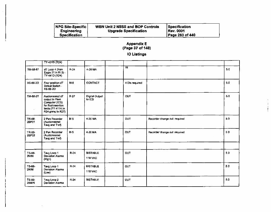
NPG Site-Specific WBN Unit 2 NSSS and BOP Controls SpecificationEngineering Upgrade Specification Rev. 0001Specification Page 283 of 440
Appendix E(Page 37 of 148)
10 Listings
TY-431D (R24)
INTM-68-67 dT Loop 4 (from R-24 4-20 MA 5.0
Eagle 21 in R13) -TY-441D (R24)
XS-68-2D Four position dT M-5 CONTACT 4 DIs required 5.0Defeat Switch -XS-6B-2D
TM-68-2T Auctioneered dT R-27 Digital Output OUT 5.0output to Plant to ICSComputer (ICS)for Rod insertionlimits (TY-411KinR24 going to R27)
TR-68- 2 Pen Recorder M-5 4-20 MA OUT Recorder change out required 5.02BP01 (Auctioneered
Tavg and Tref)
TR-68- 2 Pen Recorder M-5 4-20 MA OUT Recorder change out required 5.02SP02 (Auctioneered
Tavg and Tref)
TS-68- Tavg Loop I R-24 BISTABLE OUT 5.02MIN Deviation Alarms
(High) 118 VAC
TS-68- Tavg Loop I R-24 BISTABLE OUT 5.02NIM Deviation Alarms
(Low) 118 VAC
TS-"8- Tavg Loop 2 R-24 BISTABLE OUT 5.025M/N Deviation Alarms
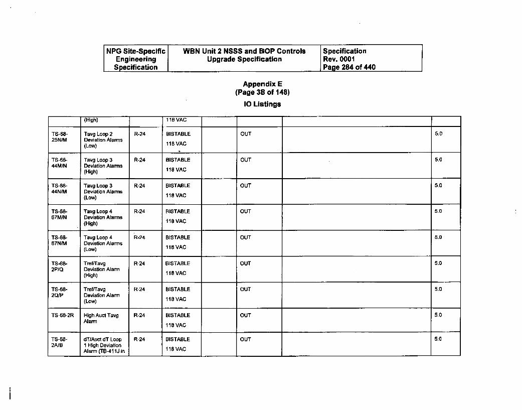
NPG Site-Specific WBN Unit 2 NSSS and BOP Controls SpecificationEngineering Upgrade Specification Rev. 0001Specification Page 284 of 440
Appendix E(Page 38 of 148)
10 Listings
(High) 118 VAC
TS-68- Tavg Loop 2 R-24 BISTABLE OUT 5.025N/M Deviation Alarms
(Low) 118 VAC
TS-68- Tavg Loop 3 R-24 BISTABLE OUT 5.044M1N Deviation Alarms
(High) 118 VAC
TS-68- Tavg Loop 3 R-24 BISTABLE OUT 5044N/M Deviation Alarms
(Low) 118 VAC
TS-68- Tavg Loop 4 R-24 BISTABLE OUT 5.067M/N Deviation Alarms
(High) 118 VAC
TS-68- Tavg Loop 4 R-24 BISTABLE OUT 5.067N/M Deviation Alarms
(Low) 118 VAC
TS-68- Tref/Tavg R-24 BISTABLE OUT 5.02P1Q Deviation Alarm
(High) 118 VAC
TS-68- Tref/Tavg R-24 BISTABLE OUT 5.02Q/P Deviation Alarm
(Low) 118 VAC
TS-68-2R High Auct Tavg R-24 BISTABLE OUT 5.0Alarm 118 VAC
TS-68- dT/Auct dT Loop R-24 BISTABLE OUT 5.02A/B 1 High Deviation
Alarm (TB-411J in 118 VAC
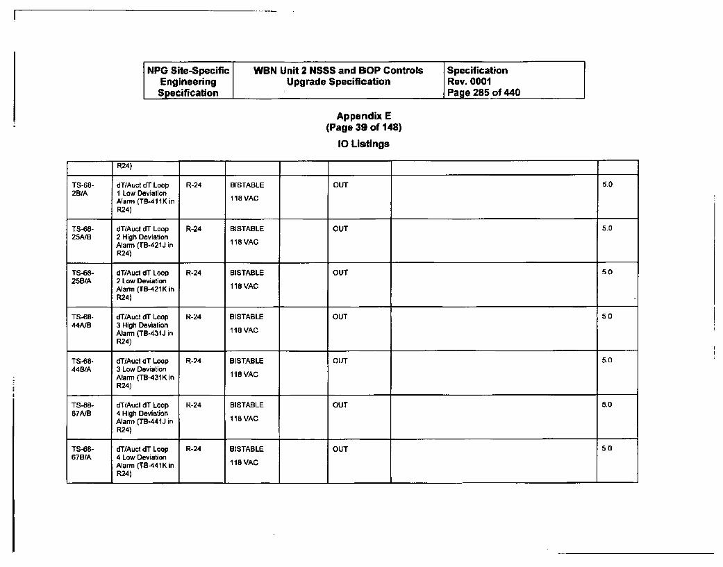
NPG Site-Specific WBN Unit 2 NSSS and BOP Controls SpecificationEngineering Upgrade Specification Rev. 0001Specification Page 285 of 440
Appendix E(Page 39 of 148)
10 Listings
R24)
TS-68- dT/Auot dT Loop R-24 BISTABLE OUT 5.02B/A I Low Deviation
Alarm (TB-41IK in 118 VAC
R24)
TS-68- dT/Auct dT Loop R-24 BISTABLE OUT 5.025NB 2 High Deviation
Alarm (TB-421J in 118 VAC
R24)
TS-68- dT/Auct dT Loop R-24 BISTABLE OUT 5.025B/A 2 Low Deviation
Alarm (TB-421K in 118 VAC
R24)
TS-68- dT/Auct dT Loop R-24 BISTABLE OUT 5.044A/B 3 High Deviation
Alarm (TB-431J in 118 VACR24)
TS-68- dT/Auct dT Loop R-24 BISTABLE OUT 5.044B/A 3 Low Deviation
Alarm (TB-431K in 118 VACR24)
TS-68- dT/Auct dT Loop R-24 BISTABLE OUT 5.067A/B 4 High Deviation
Alarm (TB-441J in 118 VACR24)
TS-68- dT/Auct dT Loop R-24 BISTABLE OUT 5.0678/A 4 Low Deviation
Alarm (TB-441K in 118 VACR24)
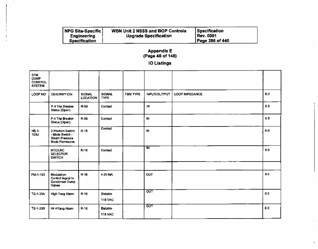
NPG Site-Specific WBN Unit 2 NSSS and GOP Controls SpecificationEngineering Upgrade Specification Rev. 0001
Specification Page 286 of 440
Appendix E(Page 40 of 148)
10 Listings
STMDUMPCONTROLSYSTEM
LOOP NO DESCRIPTION SIGNAL SIGNAL FBM TYPE INPUT/OUTPUT LOOP IMPEDANCE 6.0LOCATION TYPE
P4 Trip Breaker R-58 Contact IN 6.0Status (Open)
P-4 Trip Breaker R-58 Contact IN 60Status (Open)
ContactHS-1- 3 Position Switch R-16 IN 601030 - Mode Switch -
Steam PressureMode Permissive
INRTCILRC R-16 Contact 6.0SELECTORSWITCH
FM-1-103 Modulation R-16 4-20 MA OUT 60Control Signal toCondenser DumpValves
TS-1-33A High Tavg Alarm R-16 Bistable OUT 6.0
118VAC
TS-1-33B Hi HiTavg Alarm R-16 Bistable OUT 6.0
118 VAC
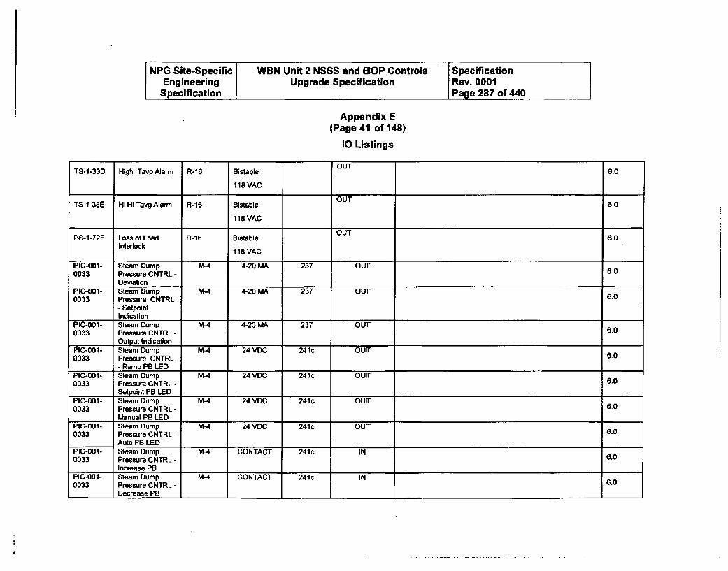
NPG Site-Specific WBN Unit 2 NSSS and BOP Controls SpecificationEngineering Upgrade Specification Rev. 0001
Specification Page 287 of 440
Appendix E(Page 41 of 148)
10 Listings
OUTTS-1-33D High Tavg Alarm R-16 Bistable 6.0
118 VAC
OUrTS-1-33E Hi Hi Tavg Alarm R-16 Bistable 6.0
118 VAC
OUTPS-1-72E Loss of Load R-16 Bistable 6.0
Interlock118 VAC
PIC-001- Steam Dump MA 4-20 MA 237 OUT0033 Pressure CNTRL - 6-0
DeviationPIC-ao1- Steam Dump MA 4-20 MA 237 OUT0033 Pressure CNTRL 6.0
- SetpointIndication
PIC-001- Steam Dump MA 4-20 MA 237 OUTi.0033 Pressure CNTRL - 6.0
1 Output IndicationPIC-001- Steam Dump M-4 24 VDC 241c OUT0033 Pressure CNTRL 60
- Ramp PB LEDPIC-001- Steam Dump MA 24 VDC 241c OUT0033 Pressure CNTRL - 6.0
Setpoint PB LEDPIC-001- Steam Dump M-4 24 VDC 241c OUT0033 Pressure CNTRL - 6.0
Manual PB LEDPIC-001- Steam Dump MA 24 VDC 241c OUT0033 Pressure CNTRL - 6.0
Auto PB LEDPIC-001- Steam Dump M-4 CONTACT 241c IN0033 Pressure CNTRL - 6.0
Increase PBPIC-001- Steam Dump MA CONTACT 241c IN0033 Pressure CNTRL - 6.0
Decrease PB I I I I
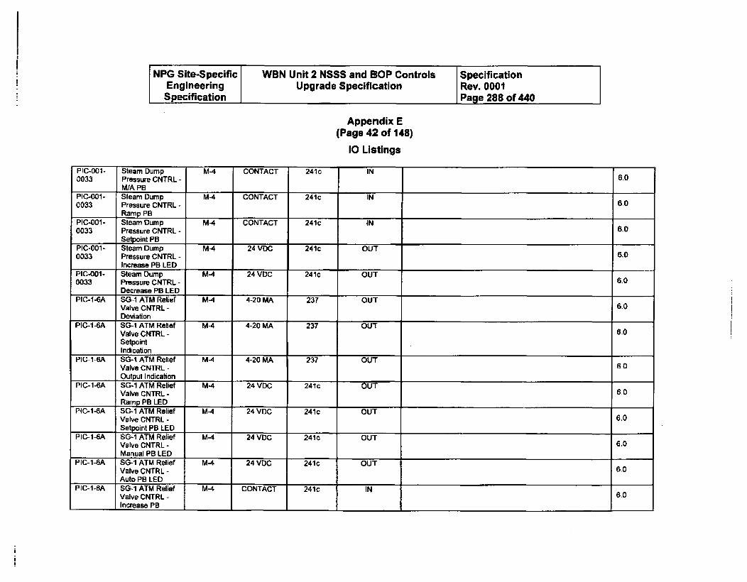
NPG Site-Specific WBN Unit 2 NSSS and BOP Controls SpecificationEngineering Upgrade Specification Rev. 0001Specification Page 288 of 440
Appendix E(Page 42 of 148)
10 Listings
PIC-001- Steam Dump M-4 CONTACT 241c IN0033 Pressure CNTRL - 6.0
WA PBPIC-001- Steam Dump M-4 CONTACT 241c IN0033 Pressure CNTRL - 60
Ramp PB1PIC-001- Steam Dump M-4 CONTACT 241c iN0033 Pressure CNTRL - 6,0
Setpoint PBPIC-00i- Steam Dump M-4 24 VOC 241c OUT0033 Pressure CNTRL - 6.0
Increase PB LEDPIC-O01- Steam Dump M-4 24 VDC 241c OUT0033 Pressure CNTRL - 6.0
Decrease PB LEDPIC-1-6A SG-i ATM Relief M-4 4-20 MA 237 OUT
Valve CNTRL - 6.0
DeviationPIC-1-6A SG-1 ATM Relief M-4 4-20 MA 237 OUT
Valve CNTRL - 6.0SetpointIndication
PIC-1-6A SG-i ATM Relief M-4 4-20 MA 237 OUTValve CNTRL - 6_0
Output IndicationPIC-1-6A SG-1 ATM Relief M-4 24 VDC 241c OUT
Valve CNTRL - 6.1
Ramp PB LEDPIC-1-6A SG-1 ATM Relief M-4 24 VOC 241c OUT
Valve CNTRL - 6.0
Setpoint PB LEDPIC-I-SA SG-I ATM Relief M-4 24 VDC 241c OUT
Valve CNTRL - 6.0Manual PB LED
PIC-1-6A SG-I ATM Relief M-4 24 VDC 241c OUTValve CNTRL - 6.0Auto PB LED
PlC-i-BA SG-1 ATM Relief M-4 CONTACT 241c INValve CNTRL - 6.0
Increase PB I I I
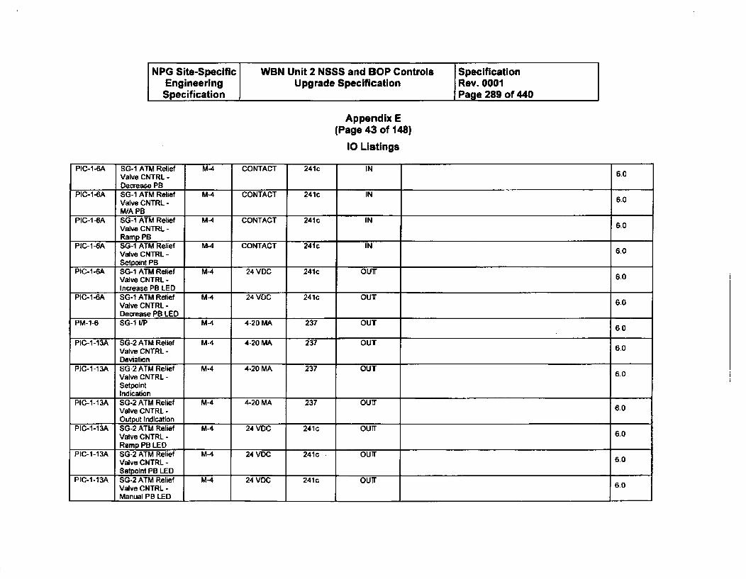
NPG Site-Specific WBN Unit 2 NSSS and BOP Controls SpecificationEngineering Upgrade Specification Rev. 0001Specification Page 289 of 440
Appendix E(Page 43 of 148)
10 Listings
PIC-1-6A SG-1 ATM Relief M-4 CONTACT 241c INValve CNTRL - 6-0
Decrease PBPIC-•-6A SO-1 ATM Relief M-4 CONTACT 241c IN
Valve CNTRL - 6.0M/A PB
PIC-IA-A SG-1 ATM Relief M4 CONTACT 241c INValve CNTRL - 6.0Ramp PB.
PIC-1-6A SG-i ATM Relief M-4 CONTACT 241c INValve CNTRL - 6.0
Setpoint PBPIC-1-6A SG-i ATM Relief M-4 24 VDC 241c ouir
Valve CNTRL - 6.0Increase PB LED
PIC-1-6A SG-i ATM Relief M-4 24 VDC 241c OUTValve CNTRL - 6.0Decrease PB LED
PM-I-6 SG-1 I/P M-4 4-20 MA 237 OUT 6.0
PIC-1-13A SG-2 ATM Relief M-4 4-20 MA 237 OUT'6Valve CNTRL - 6.0Deviation
PIC-I-13A 6G-2 ATM Relief M-4 4-20 MA 237 OUTValve CNTRL - 60
SetpointIndication
PIC-1-13A SG-2 ATM Relief M-4 4-20 MA 237 OU0Valve CNTRL - 60Output Indication
PIC-1-13A SG-2 ATM Relief M-4 24 VDC 241c ou'6.Valve CNTRL - 6,0Ramp PB LED
PIC-1-13A SG-2 ATM Relief M-4 24 VDC 241c OUTValve CNTRL - 6.0Setpoint PB LED
PIC-1-13A SG-2 ATM Relief M-4 24 VDC 241c OUT 6.0Valve CNTRL -Manual PB LED
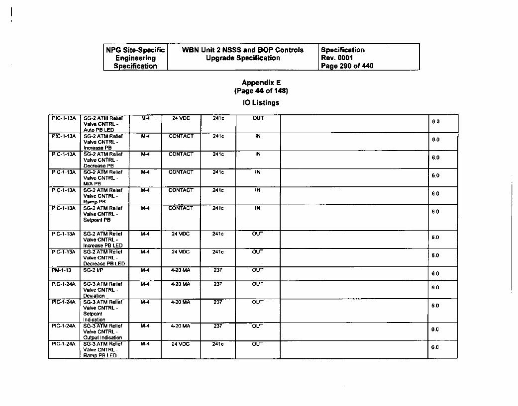
NPG Site-Specific WBN Unit 2 NSSS and SOP Controls SpecificationEngineering Upgrade Specification Rev. 0001Specification Page 290 of 440
Appendix E(Page s of 148)
10 Listings
PIC-1-13A SG-2 ATM Relief M4 24 VDC 241c OUTValve CNTRL - 60
Auto PB LEDPIC-1-13A SG-2 ATM Relief M-4 CONTACT 241c IN
Valve CNTRL - 6.0Increase PB
PIC-I-13A SG-2 ATM Relief M-4 CONTACT 241c IN 6.0Valve CNTRL -Decrease PB
PIC-1-13A SG-2 ATM Relief M-4 CONTACT 241c IN 60Valve CNTRL -M/A PB
PIC-1-13A SG-2 ATM Relief M-4 CONTACT 241c INValve CNTRL - 60Ramp PB
PIC-1-13A SG-2 ATM Relief MA CONTACT 241c INValve CNTRL - 60
Setpoint PB
PIC-1-13A SG-2 ATM Relief M-4 24 VDC 241 c OUT 5.0Valve CNTRL -
I Increase PB LEDPIC-1-13A SG-2 ATM Relief M4 24 VDC 241c OUT
Valve CNTRL - 60
Decrease PB LEDPM-1-13 SG-2 I/P M-4 4-20 MA 237 OUT 6.0
PIC-1-24A SG-3 ATM Relief M-4 4-20 MA 237 OUT 6.0Valve CNTRL -Deviation
PIC-1-24A SG-3 ATM Relief M-4 4-20 MA 237 OUT 6.0Valve CNTRL -SelpointIndication
PIC-1-24A SG-3 ATM Relief M4 4-20 MA 237 OUT6rValve CNTRL - 6.0
Output IndicationPIC-1-24A SG-3 ATM Relief M4 24 VDC 241 c OUT6.
Valve CNTRL -Ramp PB LED I 1_
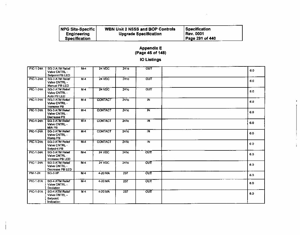
NPG Site-Specific WBN Unit 2 NSSS and BOP Controls SpecificationEngineering Upgrade Specification Rev. 0001Specification Page 291 of 440
Appendix E(Page 45 of 148)
10 Listings
PIC-1-24A SG-3 ATM Relief M- 24 VDC 241c OUT 6.0Valve CNTRL -Setpoint PB LED
PIC-1-24A SG-3 ATM Relief M-4 24 VDC 241c OUT 6.0Valve CNTRL -Manual PB LED
PIC-1-24A SG-3 ATM Relief MA 24 VDC 241c OUTValve CNTRL - 60Auto PB LED
PIC-1 -24A SG-3 ATM Relief M-4 CONTACT 241c IN 6.0Valve CNTRL -Increase PB
PIC-1-24A SG-3 ATM Relief M4 CONTACT 241c IN 6.0Valve CNTRL -Decrease PB
PIC-1-24A SG-3 ATM Relief M-4 CONTACT 241c IN 6.0Valve CNTRL -WA PB I
PIC-1-24A SG-3 ATM Relief M4 CONTACT 24C INValve CNTRL - 60Ramp PB
PIC-1-24A SG-3 ATM Relief M4 CONTACT 241c IN 6.0Valve CNTRL -Selpoint PB
PIC-1-24A SG-3 ATM Relief M-4 24 VDC 241c OUTValve CNTRL - 6.0Increase PB LED
PIC-1 -24A SG-3 ATM Relief M-4 24 VDC 241c OUT 6.0Valve CNTRL -Decrease PB LED
PM-1-24 SGO3 I/P M-4 4-20 MA 237 OUT 6.0
PIC-[-31A SO-4 ATM Relief M4 4-20 MA 237 OUTValve CNTRL - 60Deviation I
PIC-1-31A SG-4 ATM Relief MA 4-20 MA 237 OUT 6.0Valve CNTRL -SetpointIndication I
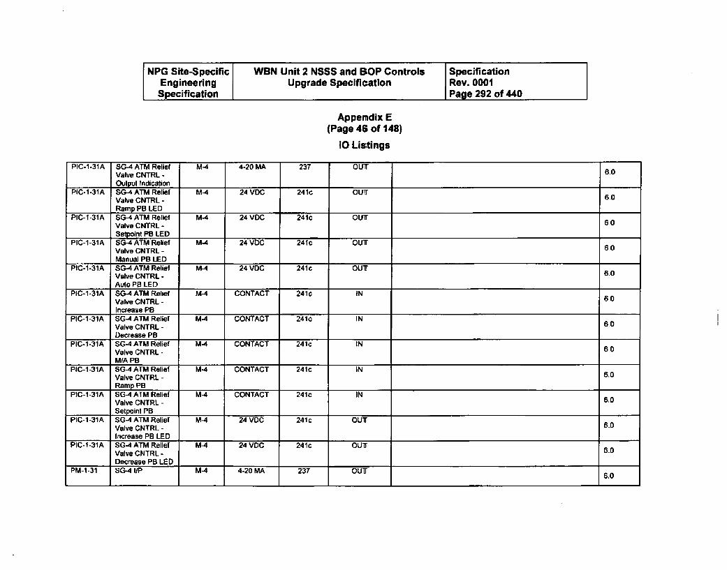
NPG Site-Specific WBN Unit 2 NSSS and BSOP Controls SpecificationEngineering Upgrade Specification Rev. 0001Specification Page 292 of 440
Appendix E(Page 46 of 148)
10 Listings
PIC-1-31A SG-4 ATM Relief M-4 4-20 MA 237 OUTValve CNTRL - 6.0
Output IndicationPIC-1-31A SG-4 ATM Relief MA 24 VDC 241c OUT
Valve CNTRL - 60Ramp PB LED
PIC-1-31A SG-4 ATM Relief MA 24 VDC 241c OUTValve CNTRL - 60Setpoint PB LED
PIC-1-31A SG-4 ATM Relief MA 24 VDC 241c OUTValve CNTRL - 60
Manual PB LEDPIC-1-31A SG-4 ATM Relief MA 24 VDC 241c OUT6
Valve CNTRL - 6.0
Auto PB LED 1,PIC-1-31A SG-4 ATM Relief M-4 CONTACT 241c IN
Valve CNTRL - 60Increase PB
PIC-1-31A SG-4 ATM Relief MA CONTACT 241c INValve CNTRL - 60Decrease PB
PIC-1-31A SG-4 ATM Relief MA CONTACT 241c INValve CNTRL - 6.0MIA PB
PIC-1-31A SG-4 ATM Relief M-4 CONTACT 241c INValve CNTRL - 6,0Ramp PB
PIC-1-31A SG-4 ATM Relief M-4 CONTACT 241c INValve CNTRL - 5.0Setpoint PB •,_
PIC-1-31A SG4 ATM Relief MA 24 VDC 241c OUTValve CNTRL - 6.0Increase PB LED
PIC-1-31A SG4 ATM Relief M-4 24 VDC 241c OUT 5.0Valve CNTRL -Decrease PB LED
PM-1-31 SG-4 I/P M4 4-20 MA 237 OUT 6.0
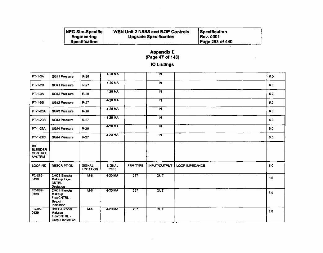
NPG Site-Specific WBN Unit 2 NSSS and BOP Controls SpecificationEngineering Upgrade Specification Rev. 0001Specification Page 293 of 440
Appendix E(Page 47 of 148)
10 Listings
4-20 MA INPT-1-2A SG#1 Pressure R-26 6.0
PT-i-2B S Presur R 4-20 MA IN 6.0
PT-i-2B SG#2 Pressure R-27 4-20 MA 6.0
PT-i-SBA SG#2 Pressure R-26 4-20 MA IN 6.04-20 MA INPT-1-20A SG#2 Pressure R-26 6.0
PT-1-27B SG#4 Pressure R-27 4t20 MA IN 6.0
BABLENDERCONTROLSYSTEM
LOOP NO DESCRIPTION SIGNAL SIGNAL FBM TYPE INPUT/OUTPUT LOOP IMPEDANCE 8.0LOCATION TYPE
0-062- CVCS Blender PA-6 4-20 MA 237 OUT0139 Makeup Flow 8.0
CNTRL -
Deviation _______
0-062- OVCS Blender MA-6 4-20 MA 237 OUT0139 Makeup
FlowCNTRL -SetpaintIndication _____ ______ _____ _______ __________________________ ____
P-062- V7 S Blender - 4-20 MA 237 OUT 8.00139 Makeup
FCowNNTRL -
_________ Output Indication _____ ______ _____ _______ _________________ ________ _____

NPG Site-Specific WBN Unit 2 NSSS and BOP Controls SpecificationEngineering Upgrade Specification Rev. 0001Specification -Page 294 of 440
Appendix E(Page 48 of 148)
10 Listings
FC-062- CVCS Blender M-6 24 VDC 241c OUT0139 Makeup 8.0
FIowCNTRL -
Ramp PB LEDFC-062- CVCS Blender M-6 24 VDC 241c OUT0139 Makeup 8.0
FlowCNTRL -Setpoint PB LED
FC-062- CVCS Blender M-6 24 VDC 241c OUT0139 Makeup so
FlowCNTRL -
Manual PB LEDFC-062- CVCS Blender M-6 24 VDC 241c OUT0139 Makeup 8.0
FlowCNTRL -
Auto PB LEDFC-062- CVCS Blender M-6 CONTACT 241c IN0139 Makeup 8.0
FlowCNTRL -
Increase PBFC-062- CVCS Blender M-6 CONTACT 241c IN0139 Makeup 8.0
FlowCNTRL -
Decrease PBFC-062- CVCS Blender M-6 CONTACT 241c IN0139 Makeup 8.0
FlowCNTRL - MA
FC-062- CVCS Blender M-6 CONTACT 241c IN0139 Makeup 8.0
FlowCNTRL -
Ramp PB,FC-062- CVCS Blender M-6 CONTACT 241c IN 8.00139 Makeup
FlowCNTRL -
Setpoint PB1FC-062- CVCS Blender M-6 24 VDC 241c OUT 8.00139 Makeup
FlowCNTRL -
I Increase PB LED

NPG Site-Specific WBN Unit 2 NSSS and BOP Controls SpecificationEngineering Upgrade Specification Rev. 0001Specification Page 295 of 440
Appendix E(Page 49 of 148)
10 Listings
FC-062- CVCS Blender M-6 24 VDC 241c OUT0139 Makeup 8.0
FlowCNTRL -Decrease PB LED
FC-062- CVCS Blender M-6 4-20 MA 237 OUT0142 Makeup Flow 8.0
CNTRL -Deviation
FC-062- CVCS Blender M-6 4-20 MA 237 OUT0142 Makeup 8.0
FlowCNTRL -SetpointIndication
FC-062- CVCS Blender M-6 4-20 MA 237 OUT0142 Makeup 8.0
FlowCNTRL -Output Indication
FC-062- CVCS Blender M-6 24 VDC 241c OUT0142 Makeup 8.0
FaowCNTRL-I Ramp PB LED
FC-062- CVCS Blender M-6 24 VDC 241c OUT0142 Makeup 8.0
FlowCNTRL -
Setpoint PB LEDFC-062- CVCS Blender M-6 24 VDC 241c OUT0142 Makeup 8.0
FloWCNTRL -Manual PB LED
FC-062- CVCS Blender M-6 24 VDC 241c OUT0142 Makeup
FlowCNTRL -Auto PB LED
FC-062- CVCS Blender M-6 CONTACT 241c IN 8.00142 Makeup 8-0
FlowCNTRL -
Increase PBFC-062- CVCS Blender M-6 CONTACT 241c IN0142 Makeup 8.0
FIowCNTRL -
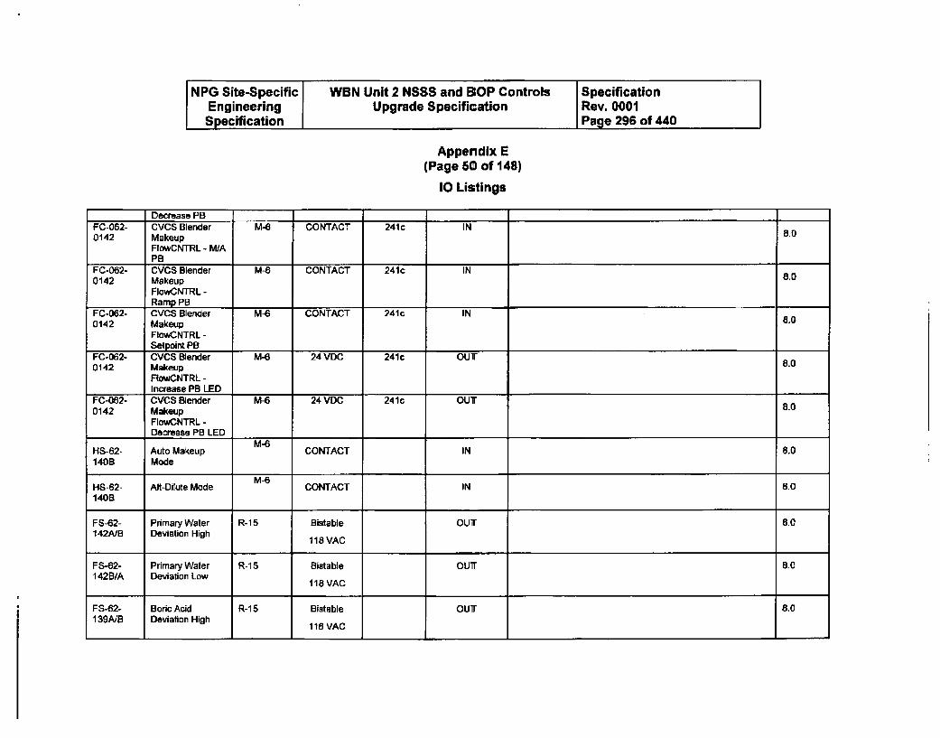
NPG Site-Specific WBN Unit 2 NSSS and SOP Controls SpecificationEngineering Upgrade Specification Rev. 0001Specification Page 296 of 440
Appendix E(Page 50 of 148)
10 Listings
Decrease PB,FC-062- CVCS Blender M-6 CONTACT 241c IN0142 Makeup 8.0
FlowCNTRL - M/APB
FC-062- CVCS Blender M-6 CONTACT 241c IN0142 Makeup 8.0
FlowCNTRL -Ramp PB I
FC-062- CVCS Blender M-6 CONTACT 241c IN0142 Makeup 8.O
FlowCNTRL -Setpoint PB
FC-062- CVCS Blender M-6 24 VDC 241c OUT0142 Makeup 8.0
FlowCNTRL -
Increase PB LEDFC-062- CVCS Blender M-6 24 VDC 241c OUT 8.00142 Makeup
FIowCNTRL -Decrease PB LED
M-6HS-62- Auto Makeup CONTACT IN 8.0140B Mode
HS-62- Alt-Dilute Mode CONTACT IN 8.0140B
FS-62- Primary Water R-1 5 Bistable OUT 8.0142A/B Deviation High 118VAC
FS-"2- Primary Water R-15 Bistable OU1T 8.0142B/A Deviation Low 118 VAC
FS-62- Boric Acid R-1 5 Bistable OUT 8.0139A/B Deviation High 118 VAC
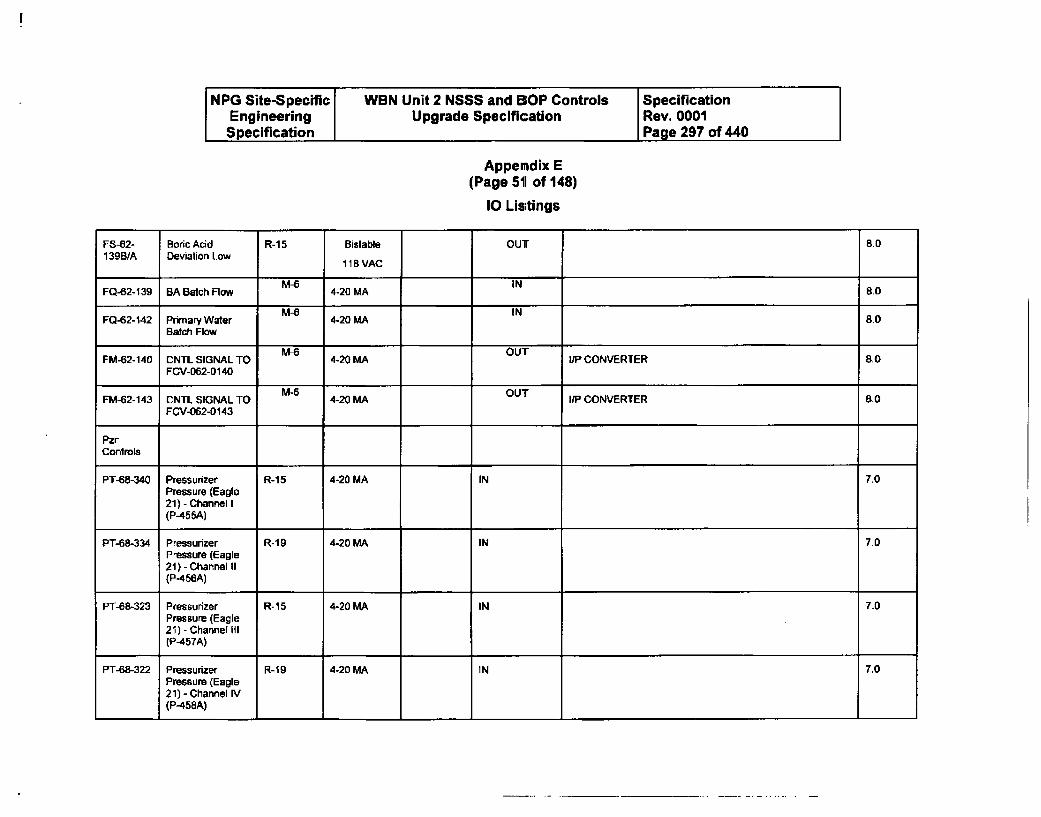
NPG Site-Specific WBN Unit 2 NSSS and BOP Controls SpecificationEngineering Upgrade Specification Rev. 0001Specification Page 297 of 440
Appemdix E(Page 51 of 148)
10 Listings
FS-62- Boric Acid R-1 5 Bistable OUT 8.0139BJA Deviation Low 118 VAC
M-6 INFQ-62-139 BA Batch Flow 4-20 MA 8,0
M-6 INFO-62-142 Primary Water 4-20 MA 8.0
Batch FlowM-I OUT
FM-62-140 CNTL SIGNAL TO 4-20 MA I/PCONVERTER 8.0FCV-062-0140
FM-62-143 CNTL SIGNAL TO M5 4-20 MA OUT I/P CONVERTER 8.0FCV-062-0143
PzrControls
PT-68-340 Pressurizer R-15 4-20 MA IN 7.0Pressure (Eagle21) - Channel I(P-455A)
PT-68-334 Pressurizer R-19 4-20 MA IN 7.0Pressure (Eagle21) - Channel II(P-456A)
PT-68-323 Pressurizer R-15 4-20 MA IN 7.0Pressure (Eagle21)- Channel Ill(P-457A)
PT-68-322 Pressurizer R-19 4-20 MA IN 7.0Pressure (Eagle21) - Channel IV(P-458A)
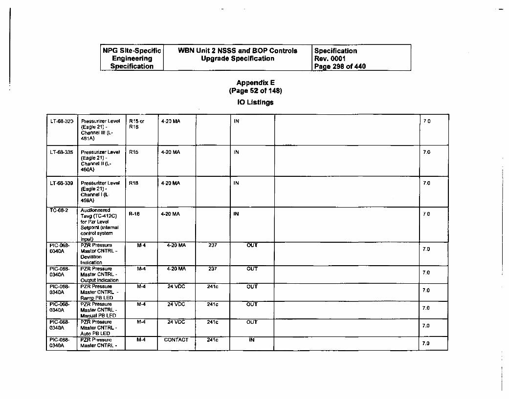
NPG Site-Specific WBN Unit 2 NSSS and BOP Controls SpecificationEngineering Upgrade Specification Rev. 0001Specification Page 298 of 440
Appemdix E(Page 52 of 148)
10 Listings
LT-68-320 Pressurizer Level R15 or 4-20 MA IN 7.0(Eagle 21) - R18Channel III (L-461A)
LT-68-335 Pressurizer Level R15 4-20 MA IN 7.0(Eagle 21) -Charnel II (L-460A)
LT-68-339 Pressurizer Level R18 4-20 MA IN 7.0(Eagle 21) -Channel I (L-459A)
TC-68-2 AuctioneeredTavg (TC-412C) R-18 4-20 MA IN 7.0
for Pzr LevelSetpoint (internalcontrol systeminput)
PIC-068- PZR Pressure M-4 4-20 MA 237 OUT0340A Master CNTRL - 7.0
DeviationIndication
PIC-068- PZR Pressure M-4 4-20 MA 237 OUT0340A Master CNTRL - 7.0
Output IndicationPIC-068- PZR Pressure M-4 24 VDC 241c OUT0340A Master CNTRL - 7.0
Ramp PB LEDPIC-068- PZR Pressure M-4 24 VDC 241 c OUT0340A Master CNTRL - 7.0
Manual PB LEDPIC-068- PZR Pressure M-4 24 VDC 241c OUT0340A Master CNTRL - 7.0
Auto PB LEDPIC-068- PZR Pressure M-4 CONTACT 241c IN0340A Master CNTRL - 7.0
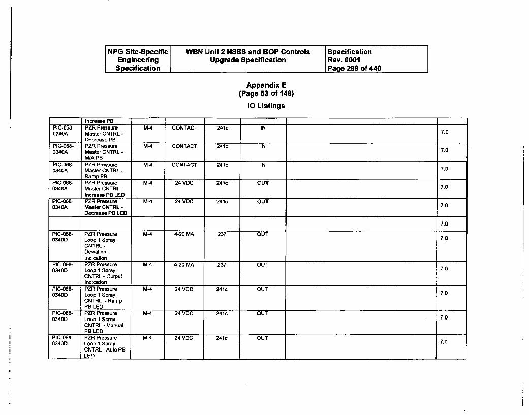
NPG Site-Specific WBN Unit 2 NSSS and BOP Controls SpecificationEngineering Upgrade Specification Rev. 0001Specification Page 299 of 440
Appemdix E(Page 53 of 148)
10 Listings
I Increase PBPIC-068- PZR Pressure M-4 CONTACT 241 c IN0340A Master CNTRL - 7.0
Decrease PBPIC-068- PZR Pressure M-4 CONTACT 241c IN0340A Master CNTRL - 7.0
MIA PBPIC-068- PZR Pressure M-4 CONTACT 241c IN0340A Master CNTRL - 7.0
Ramp PBPIC-068- PZR Pressure MA 24 VDC 241C OUT0340A Master CNTRL - 7.0
Increase PB LEDPIC-068- PZR Pressure M-4 24 VDC 241c OUT0340A Master CNTIRL - 70
Decrease PB LED
7.0
PIC-068- PZR Pressure M-4 4-20 MA 237 OUT0340D Loop 1 Spray 7.0
CNTRL -
DeviationIndication
PIC-068- PZR Pressure M-4 4-20 MA 237 OUT0340D Loop 1 Spray 7.0
CNTRL - OutputIndication 1 1
PIC-068- PZR Pressure M-4 24 VDC 241c OUT0340D Loop 1 Spray 7.0
CNTRL - RampPB LED
PIC-068- PZR Pressure M-4 24 VDC 241c OUT0340D Loop I Spray 7.0
CNTRL - ManualPB LED
PIC-068- PZR Pressure M-4 24 VDC 241c OUT0340D Loop 1 Spray 7.0
CNTRL - Auto PBLEDI
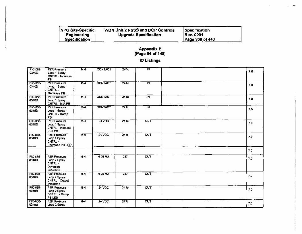
NPG Site-Specific WBN Unit 2 NSSS and BOP Controls SpecificationEngineering Upgrade Specification Rev. 0001Specification Page 300 of 440
Appendix E(Page 54 of 148)
10 Listings
PIC-068- PZR Pressure M-4 CONTACT 241c IN 7.00340D Loop 1 Spray
CNTRL - IncreasePS
PIC-068- PZR Pressure M-4 CONTACT 241c IN0340D Loop 1 Spray 7-0
CNTRL-Decrease PB
PIC-068- PZR Pressure M-4 CONTACT 241c IN0340D Loop 1 Spray 7.0
CNTRL - M/A PB13PIC-068- PZR Pressure M-4 CONTACT 241c IN0340D Loop I Spray 7.0
CNTRL - RampPB
PIC-068- PZR Pressure MA 24 VDC 241c OUT 7.003400 Loop I Spray
CNTRL - IncreasePB LED
PIC-068- PZR Pressure M-4 24 VDC 241c OUT0340D Loop 1 Spray 7.0
CNTRL -
Decrease PB LED
7-0
PIC-068- PZR Pressure M-4 4-20 MA 237 OUT 7.00340B Loop 2 Spray
CNTRL -
DeviationIndication
PIC-068- PZR Pressure M-4 4-20 MA 237 OUT7.0340B Loop 2 Spray 7.0
CNTRL - OutputIndication
PIC-068- PZR Pressure M-A 24 VDC 241c OUT 1.0340B Loop 2 Spray 7.0
CNTRL - RampPB LED
PIC-068- PZR Pressure M-4 24 VDC 241c OUT 7.00340B Loop 2 Spray 7.0 IIIII_
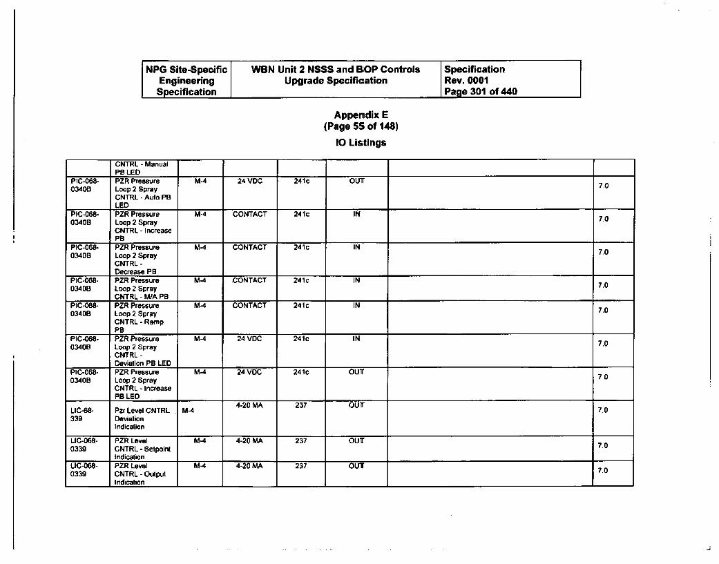
NPG Site-Specific WBN Unit 2 N$SS and BOP Controls SpecificationEngineering Upgrade Specification Rev. 0001Specification Page 301 of 440
Appendix E(Page 55 of 148)
10 Listings
CNTRL - ManualPB LED
PIC-068- PZR Pressure M-4 24 VDC 241c OUT03408 Loop 2 Spray 70
CNTRL - Auto PBLED
PIC-068- PZR Pressure M-4 CONTACT 241c IN70340B Loop 2 Spray 7.0
CNTRL - IncreaseSPB
PIC-068- PZR Pressure M-4 CONTACT 241c IN 7.00340B Loop 2 Spray
CNTRL -
Decrease PBPIC-068- PZR Pressure M-4 CONTACT 241c IN 7.003408 Loop 2 Spray
CNTRL - MA PBPIC-068- PZR Pressure M4 CONTACT 241 c IN 7.003408 Loop 2 Spray
CNTRL - RampPB
PIC-068- PZR Pressure M4 24 VDC 241c IN 7.00340B Loop 2 Spray
CNTRL -
Deviation PB LEDPIC-068- PZR Pressure MA4 24 VDC 241c OUT03408 Loop 2 Spray 7.0
CNTRL - IncreasePB LED
LIC-68- Pzr Level CNTRL M 4-20 MA 237 OUT 7.0339 Deviation
Indication
LIC-068- PZR Level M4 4-20 MA 237 OUT0339 CNTRL - Setpoint 7.0
IndicationLIC-068- PZR Level M4 4-20 MA 237 OUT 7.00339 CNTRL - Output
Indication I
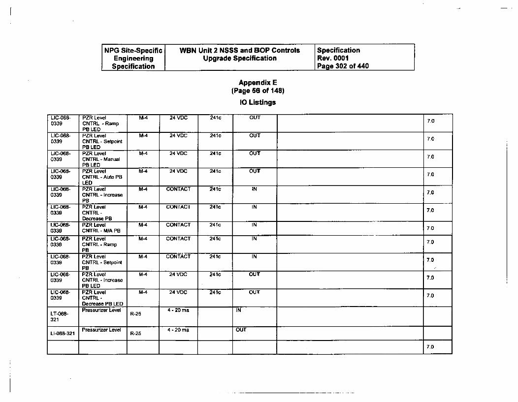
NPG Site-Specific WBN Unit 2 NSSS and BOP Controls SpecificationEngineering Upgrade Specification Rev. 0001Specification Page 302 of 440
Appendix E(Page 58 of 148)
10 Listings
LIC-068- PZR Level M-4 24 VDC 241c OUT0339 CNTRL - Ramp 7.0
PB LEDLIC-068- PZR Level M-4 24 VOC 241c OUT 7O0339 CNTRL - Setpoint
PB LEDLIC-068- PZR Level M-4 24 VDC 241c OUT0339 CNTRL - Manual 7.0
PB LEDLIC-068- PZR Level M41 24 VDC 241c OUT 7.00339 CNTRL - Auto PB
LED ILIC-068- PZR Level M-4 CONTACT 241C IN 7.00339 CNTRL - Increase
PBLIC-068- PZR Level M-4 CONTACT 241c IN 7-00339 CNTRL -
Decrease PBLIC-068- PZR Level M-4 CONTACT 241c IN 7.00339 CNTRL - WA PB
LIC-068- PZR Level M-4 CONTACT 241c IN 7.00339 CNTRL - Ramp
PBLIC-068- PZR Level M-4 CONTACT 241c IN0339 CNTRL - Setpoint 7.0
PBLIC-068- PZR Level M-4 24 VDC 241c OUT 7.00339 CNTRL - Increase
PB LEDLIC-068- PZR Level M-4 24 VDC 241c OUT 7.00339 CNTRL -
Decrease PB LEDPressurizer Level 4 - 20 ma INLT-088- R-25
321
Pressurizer Level 4-20ma OUTLI-068-321 R-25
7.0
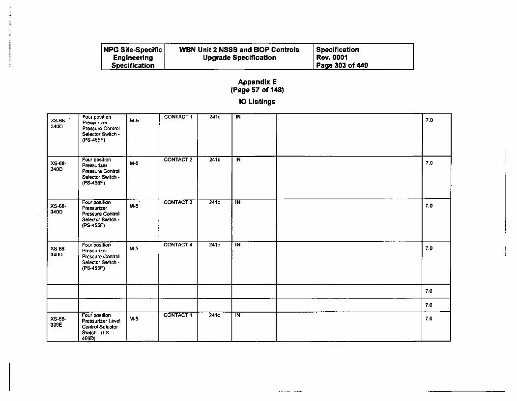
NPG Site-Specific WBN Unit 2 NSSS and BOP Controls SpecificationEngineering Upgrade Specification Rev. 0001Specification Page 303 of 440
Appendix E(Page 57 of 148)
10 Listings
X548 Four position M-5 CONTACT 1 241c IN 70Pressurizer340D Pressure Control
Selector Switch -(PS-455F)
Four position CONTACT 2 241c INXS-68- Pressurizer M-5 7.0340D Pressure Control
Selector Switch -(PS-455F)
Four position CONTACT 3 241c INXS-68- Pressurizer M-5 7.0340D Pressure Control
Selector Switch -(PS-455F)
Four position M-5 CONTACT 4 241c IN 7.0Pressurizer340D Pressure Control
Selector Switch -(PS-455F)
7.0
7.0
Four position CONTACT1 241c IN0Pressurizer Level M-5 C2
339E Control SelectorSwitch - (LS-459D)
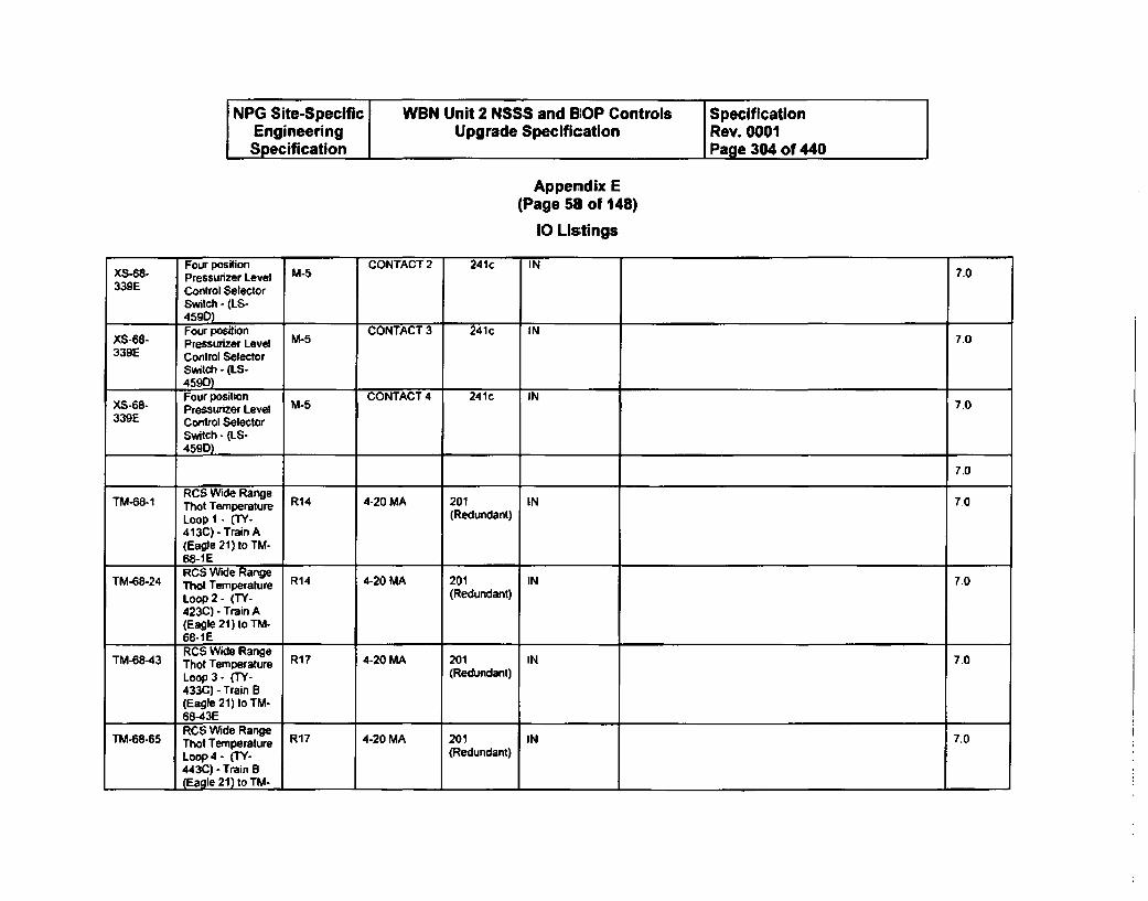
NPG Site-Specific WBN Unit 2 NSSS and BOP Controls SpecificationEngineering Upgrade Specification Rev. 0001Specification Page 304 of 440
Appendix E(Page 58 of 148)
10 Listings
Four position CONTACT 2 24.c INPressurizer Level M-5 C Tc
339E Control Selector
Switch - (LS-
Four position CONTACT 3 241c INXS-68- Pressurizer Level M-5 7.0
339E Control SelectorSwitch - (LS-459D)
XS-68- Four position CONTACT 4 241c IN33-68- Pressurizer Level CNA 4 21 I339E Control Selector
Switch - (IS-459D).
7.0
RCS Wide RangeTM-68-1 That Temperature R14 4-20 MA 201 IN 7.0
Loop 1 - (TY- (Redundant)413C) - Train A(Eagle 21) to TM-68-1 ERCS Wide Range
TM-68-24 That Temperature R14 4-20 MA 201 IN 7.0
Loop 2 - (TY- (Redundant)
423C) - Train A(Eagle 21) to TM-68-IERCS Wide Range
TM-68-43 Thot Temperature R17 4-20 MA 201 IN 7.0
Loop 3 - (TY- (Redundant)433C) - Train B(Eagle 21) to TM-68-43ERCS Wide Range
TM-68-65 ThOt Temperature R17 4-20 MA 201 IN 7.0
Loop 4 - (TY- (Redundant)443C) - Train B(Eagle 21) to TM.
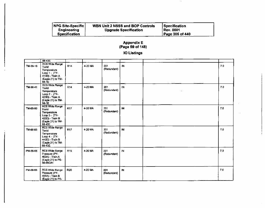
NPG Site-Specific WBN Unit 2 NSSS and BOP Controls SpecificationEngineering Upgrade Specification Rev. 0001Specification Page 305 of 440
Appendix E(Page 59 of 148)
10 Listings
68-43ERCS Wide RangeTM-68-18 TCWid R14 4-20 MA 201 IN 7.0
Temperature (Redundant)Loop 1 - (TY-413D) - Train A(Eagle 21) to TM-68-1ERCS Wide Range
TM-68-41 Twold R14 4-20 MA 201 IN 7.0
Temperature (Redundant)
Loop 2 - (TY-423D) - Train A(Eagle 21) to TM-68-1 E
TM-68-60 CWde Range R17 4-20 MA 201 IN 7.0TM80 Tcold10
Temperature (Redundant)Loop 3 - (TY-433D) - Train B(Eagle 21) to TM-
I 68-43ETM-68-83 RCS Wide Range R17 4-20 MA 201 IN 7.0
Temperature (Redundant)Loop 4 - (TY-443D) - Train B(Eagle 21) to TM-68-43E
PM-68-66 RCS Wide Range R15 4-20 MA 201 IN 7.0Pressure (PY- (Redundant)403A) - Train A(Eagle 21) to PS-68-66G/H
PM-68-68 RCS Wide Range R20 4-20 MA 201 IN 7.0Pressure (PY- (Redundant)405A) - Train B(Eagle 21) to PS-
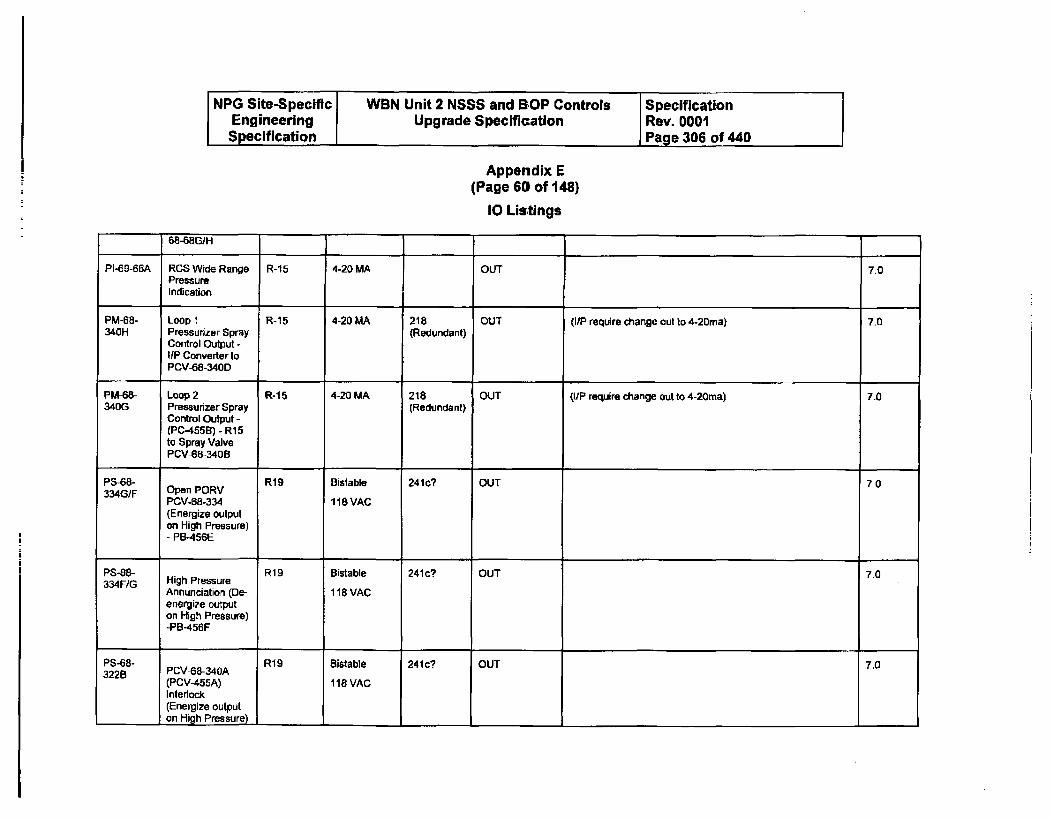
NPG Site-Specific WBN Unit 2 NSSS and SOP Controls SpecificationEngineering Upgrade Specification Rev. 0001Specification Page 306 of 440
Appendix E(Page 60 of 148)
10 Listings
68-MBG/H
PI-69-66A RCS Wide Range R-15 4-20 MA OUT 7.0PressureIndication
PM-68- Loop I R-15 4-20 MA 218 OUT (I/P require change cut to 4-20ma) 7.0340H Pressurizer Spray (Redundant)
Control Output -IUP Converter toPCV-68-340D
PM-68- Loop 2 R-15 4-20 MA 218 OUT (I/P require change out to 4-20ma) 7.0340G Pressurizer Spray (Redundant)
Control Output -(PC-455B) - R15to Spray ValvePCV-68-340B
PS-68- R19 Bistable 241c? OUT 7.0334G/F Open PORV
PCV-68-334 118 VAC(Energize outputon High Pressure)- PB-456E
PS-GB- R19 Bistable 241c? OUT 7.0334F/G High Pressure
Annunciation (De- 118 VACenergize outputon High Pressure)-PB-456F
PS-68- R19 Bistable 241c? OUT 7.03228 PCV-68-340A
(PCV-455A) 118 VACInterlock(Energize outputon High Pressure) 1
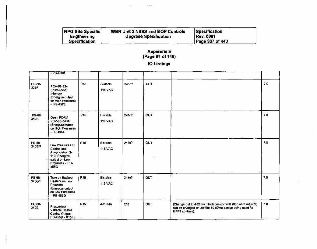
NPG Site-Specific WBN Unit 2 NSSS and BOP Controls SpecificationEngineering Upgrade Specification Rev. 0001Specification Page 307 of 440
Appendix E(Page 611 of 148)
10 Listings
- PB-4588
PS-68- R15 Bistable 241c? OUT 7.0323F PCV-68-334(PCV-456A) 118 VACInterlock(Energize outputon Hsgh Pressure)- PB-457E
PS-68- R15 Bistable 241c? OUT 7.0340H Open PORV
PCV-68-340A 118 VAC(Energize outputon High Pressure)- PB455E
PS-68- R15 Bistable 241c? OUT 7.0340G/F Low Pressure Htr
Control and 118 VACAnnunciation 2-110 (Energizeoutput on LowPressure) - PB-455G
PS-68- Turn on Backup R15 Bistable 241c? OUT 7.0340G/F Heaters an Low
Pressure 118 VAC(Energize outputan Low Pressure)- PB-455G
PC-68- R15 4-20 MA 218 OUT (Change out to 4-20ma if Robicon controls (680 ohm resistor) 7.0340E Pressurizer can be changed or use the 10-50ma design being used forVariable Heater MFPT controls).
Control Output -PC-455D - R15 to

NPG Site-Specific WBN Unit 2 NSSS and BOP Controls SpecificationEngineering Upgrade Specification Rev. 0001Specification I Page 308 of 440
Appemdix E(Page 62 of 148)
10 Listings
Robicon SCRheater controlinput
Two PenLR-68-339 Recorder with Pzr R-24 4-20 MA 218 OUT (Recorder change to 4-20ma required) 7.0P002 Level Setpoint
Program Value(function of Tavg)
LS-68- +5% High Level7.LS-68- Deviation R18 Bistable 241c? OUT 7.0339./F Annunciation 2- 118 VAC
117 (Energizeoutput on HighLevel) - LB-459E-5% Low Level
LS-68- Deviation R18 Bistable 241c? OUT 7.0339F1E Annunciation 14- 118 VAC
65 (Energizeoutput on LowLevel) - LB-459F17% Low Level
LS-68- Letdown Isolation R15 Bistable 241c? OUT (Look at need for separate outputs for each function) 70335E/D (Close FCV-62- 118 VAC
69), LetdownOrifice Isolation(Closes FCV-02-72, -73, & -74),and Annunciation2-116 (Energizeoutput on LowLevel) - LB-460D ,..17% Low Level
LS-68- Letdown Isolation R18 Bistable 241 c? OUT (Look at need for separate outputs for each function) 7.0339D (Close FCV-62- 118 VAC
70), LetdownOrifice Isolation(Closes FCV-62-72, -73, & -74),and Annunciation
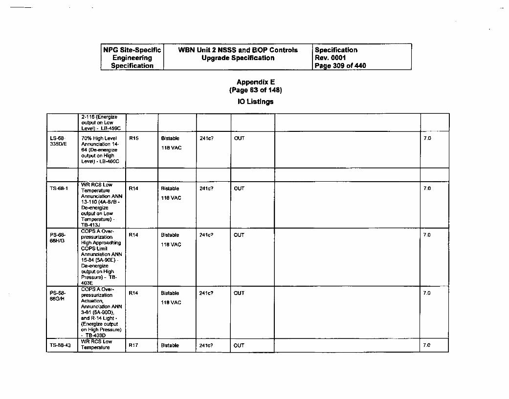
NPG Site-Specific WBN Unit 2 NSSS and BOP Controls SpecificationEngineering Upgrade Specification Rev. 0001Specification Page 309 of 440
Appendix E(Page 63 of 148)
10 Listings
2-116 (Energizeoutput on Low
,._ Level) - LB-459C
LS-68- 70% High Level R15 Bistable 241c? OUT 7.0335DIE Annunciation 14-
64 (De-energize 118 VAC
output on HighLevel) - LB-460C
TS-68-1 WR RCS Low R14 Bistable 241c? OUT 7.0TemperatureAnnunciation ANN 118 VAC13-110 (4A-67B -De-energizeoutput on LowTemperature) -TB-413JCOPS A Over-
PS-68- pressurization R14 Bistable 241c? OUT 7.066HIG High Approaching 118 VAC
COPS LimitAnnunciation ANN1 5-84 (5A-90E) -De-energizeoutput on HighPressure)- TB-403ECOPS A Over-pressurization R14 Bistable 241? OUT 70
66G/H Actuation. 118 VAC
Annunciation ANN3-61 (5A-90D),and R-14 Light -(Energize outputon High Pressure)- TB-403DWR RCS Low
TS-68-43 Temperature R17 Bistable 241c? OUT 7.0
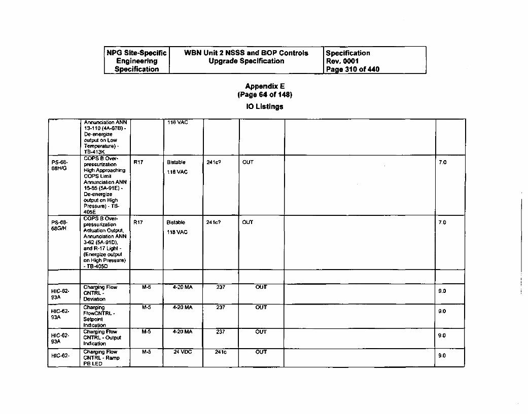
NPG Site-Specific WBN Unit 2 NSSS and BOP Controls SpecificationEngineering Upgrade Specification Rev. 0001Specification I Page 310 of 440
Appendix E(Page 64 of 148)
10 Listings
Annunciation ANN 118 VAC13-1110 (4A-67B) -De-energizeoutput on LowTemperature) -TB-413K
P8-68- COPS B Over- R1 Bistable 241c? OUT 7.0pressurization68H!G High Approaching 118 VAC
COPS LimitAnnunciation ANN15-85 (5A-91E) -De-energizeoutput on HighPressure) - TB-405E
P8-88- COPS B Over- R17 Bistable 241c7 OUT 7.0pressurization68GIH Actuation Output, 118 VAC
Annunciation ANN3-62 (SA-91D),and R-17 Light -(Energize outputon High Pressure)- Tr-405D
Charging Flow M-5 4-20 MA 237 OUrHIC-62- CNTRL - 9.093A Deviation
Charging M-5 4-20 MA 237 OUTHIC-62- FIowCNTRL - 9.093A Setpoint
IndicationCharging Flow M-5 4-20 MA 237 OUT'90
HIC-62- CNTRL- Output 9-0g3A Indication
Charging Flow M-5 24 VDC 241c OUT 9.0HIC-62- CNTRL-Ramp
PB LED I I I I
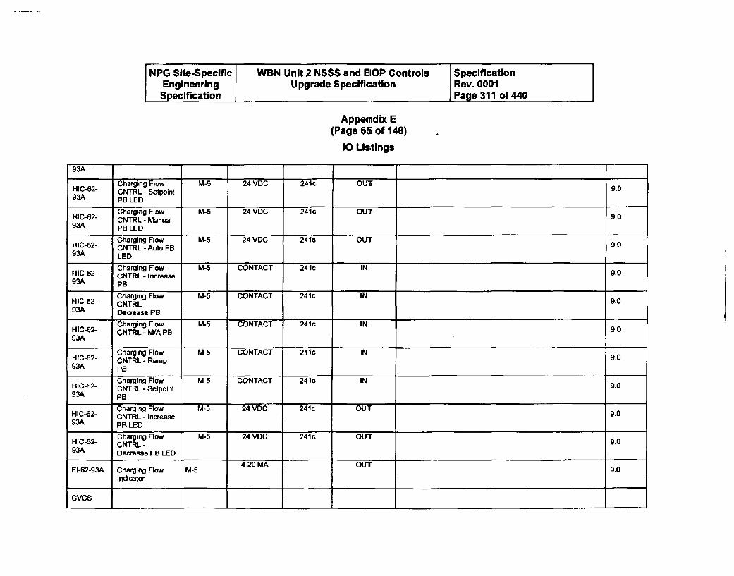
NPG Site-Specific WBN Unit 2 NSSS and B1OP Controls SpecificationEngineering Upgrade Specification Rev. 0001
Specification Page 311 of 440
Appendix E(Page 65 of 148)
10 Listings
93A
Charging Flow M-5 24 VDC 241c OUTHIC-62- CNTRL - Setpoint 9093A PB LED
Charging Flow M-5 24 VDC 241c OUTHIC-62- CNTRL - Manual 9.093A PB LED
Charging Flow M-5 24 VDC 241c OUTHIC-62- CNTRL - Auto PB 9.093A LED
Charging Flow M-5 CONTACT 241c INHIC-62- CNTRL - Increase 9-093A PB
Charging Flow M-5 CONTACT 241c INHIC-62- CNTRL - 9-093A Decrease PB
Charging Flow M-5 CONTACT 241C INHIC-62- CNTRL - MIA PB 9.093A
Charging Flow M-5 CONTACT 241c INHIC-62- CNTRL - Ramp 9.093A PB
Charging Flow M-5 CONTACT 2410 INHIC-62- CNTRL - Setpoint 9.093A PB
Charging Flow M-5 24 VDC 241c OUT9.0HIC-62- CNTRL - Increase 9.093A PB LED
Charging Flow M-5 24 VDC 2410 OUTHIC-62- CNTRL- 9.093A Decrease PB LED
4-20 MA OUTFI-62-93A Charging Flow M-5 9.0
Indicator
CVCS
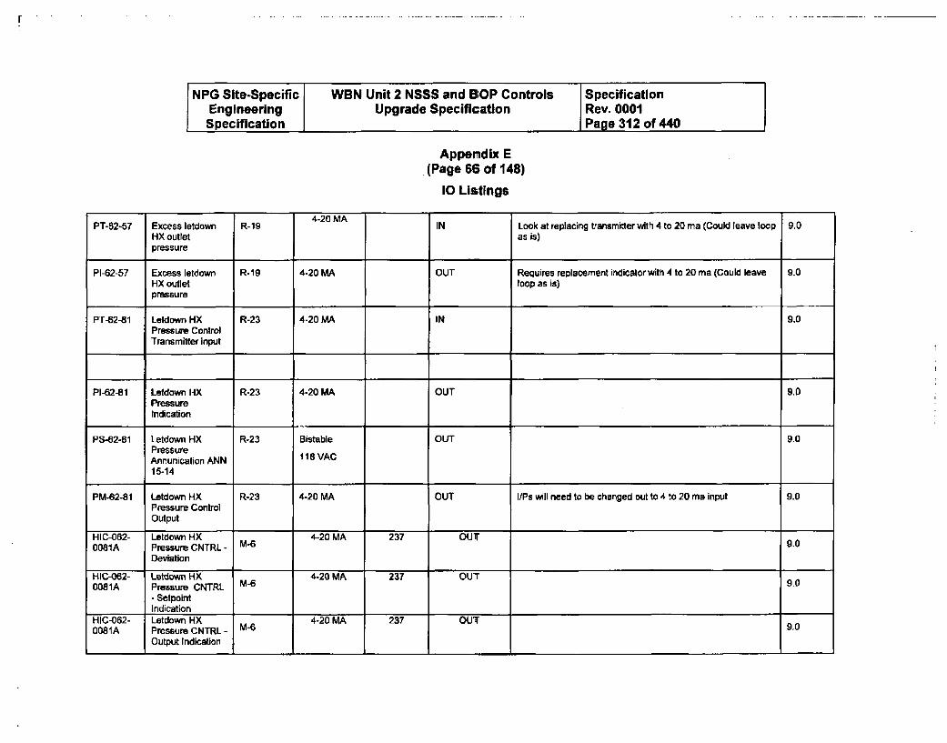
F
NPG Site-Specific WBN Unit 2 NSSS and BOP Controls SpecificationEngineering Upgrade Specification Rev. 0001Specification Page 312 of 440
Appendix E(Page 68 of 148)
10 Listings
4-20 MAPT-52-57 Excess letdown R-19 IN Look at replacing transmitter with 4 to 20 ma (Could leave loop 9.0
HX outlet as is)pressure
PI-62-57 Excess letdown R-19 4-20 MA OUT Requires replacement indicator with 4 to 20 ma (Could leave 9.0HX outlet loop as is)pressure
PT-62-81 Letdown HX R-23 4-20 MA IN 9.0Pressure ControlTransmitter input
PI-62-81 Letdown HX R-23 4-20 MA OUT 9.0PressureIndication
PS-62-81 Letdown HX R-23 Bistable OUT 9.0PressureAnnunication ANN 118 VAC
15-14
PM-62-81 Letdown HX R-23 4-20 MA OUT I/Ps will need to be changed out to 4 to 20 ma input 9.0Pressure ControlOutput
HIC-062- Letdown HX 4-20 MA 237 OUT0081A Pressure CNTRL - M-6 9.0
Deviation
HIC-062- Letdown HX 4-20 MA 237 OUT0081A Pressure CNTRL M-6 9.0
- SetpointIndication
HIC-062- Letdown HX 4-20 MA 237 OUT0081A Pressure CNTRL - M- 9.0
Output Indication
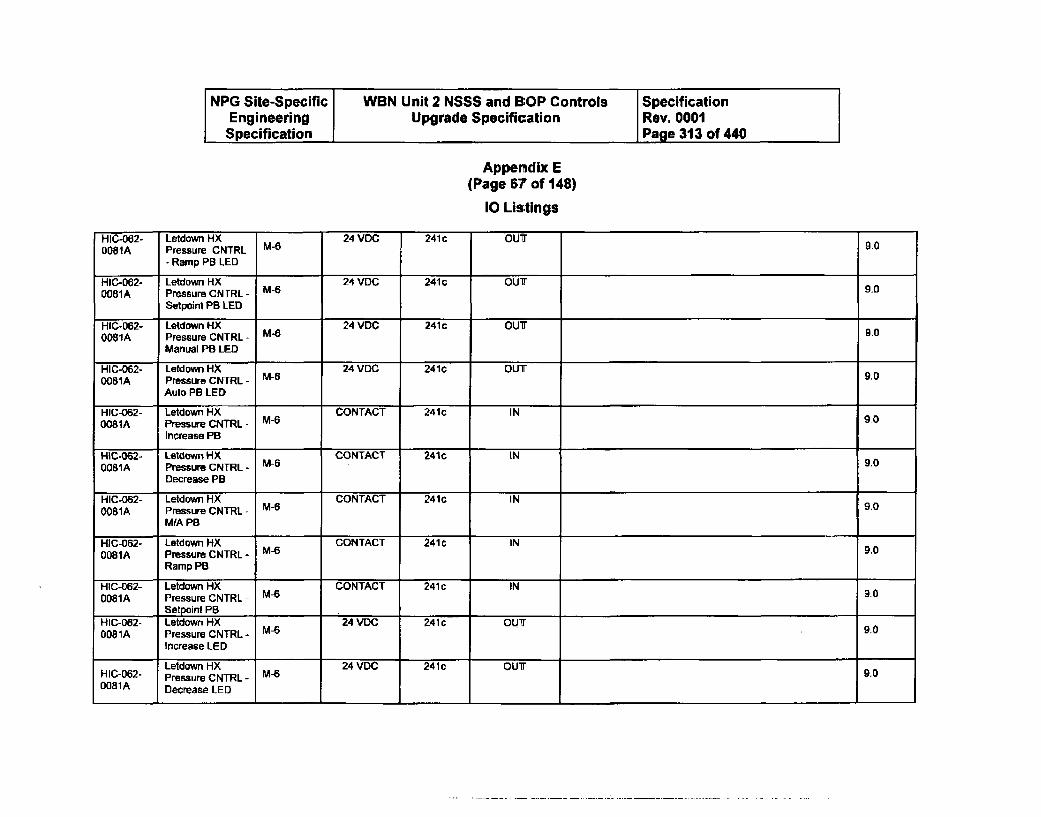
NPG Site-Specific WBN Unit 2 NSSS and BOP Controls SpecificationEngineering Upgrade Specification Rev. 0001Specification Page 313 of 440
Appendix E(Page 67 of 148)
10 Listings
HIC-062- Letdown HX 24 VDC 241 c OUT0081A Pressure CNTRL 9.0
- Ramp PB LED
HIC-062- Letdown HX 24 VDC 241c OUT0081A Pressure CNTRL- M6 9.0
Setpoint PB LED
HIC-062- Letdown HX 24 VDC 241c OUT0081A Pressure CNTRL - M-6 9.0
Manual PB LED
HIC-062- Letdown HX 24 VDC 241c OUT0081A Pressure CNTRL - M-6 9.0
Auto PB LED
HIC-062- Letdown HX CONTACT 241c IN0081A Pressure CNTRL - M6 90
Increase PB
HIC-062- Letdown HX CONTACT 241c IN0081A Pressure CNTRL - M-6 9,0
Decrease PB
HIC-062- Letdown HX CONTACT 241c IN0081A Pressure CNTRL - M-6 9.0
MIA PB
HIC-062- Letdown HX CONTACT 241c IN0081A Pressure CNTRL - M-6 9.0
Ramp PB
HIC-062- Letdown X M_6 CONTACT 241 c IN0081A Pressure CNTRL- -9.0
Setpoint PBHIC-062- Letdown HX 24 VDC 241c OUT0081A Pressure CNTRL- M-6 9.0
Increase LED
Letdown HX 24 VDC 241c OUTHIC-062- Pressure CNTRL - M-6 9.00081A Decrease LED
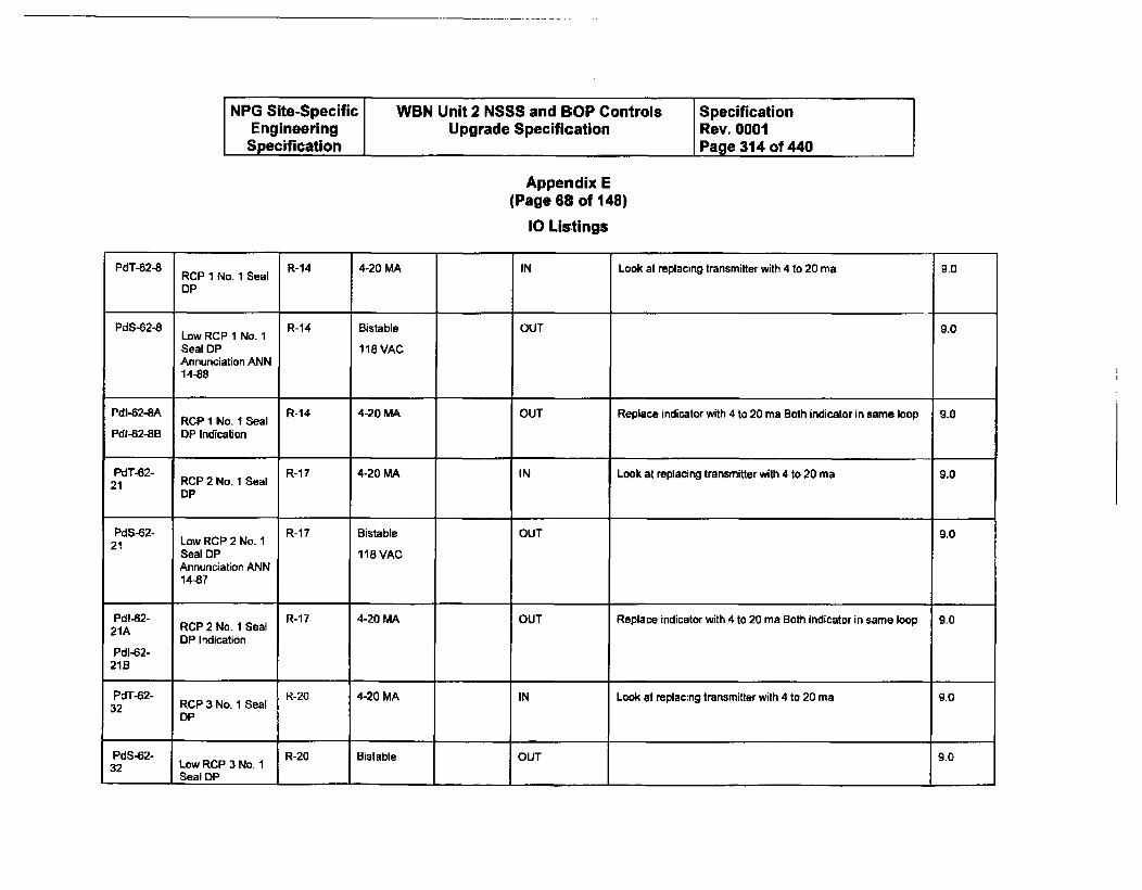
NPG Site-Specific WBN Unit 2 NSSS and BOP Controls SpecificationEngineering Upgrade Specification Rev. 0001Specification Page 314 of 440
Appendix E(Page 68 of 148)
10 Listings
PdT-62-8 RCP 1 No. 1 Seal R-14 4-20 MA IN Look at replacing transmitter with 4 to 20 ma 9.0
DP
PdS-62-8 R-14 Bistable OUT 9.0Low RCP 1 No. 1
Seal DP 118 VACAnnunciation ANN14-88
Pdi-62-SA RCP 1 No. I Seal R-14 4-20 MA OUT Replace indicator with 4 to 20 ma Both indicator in same loop 9.0
PdM-62-8B DP Indication
PdT-62- R-17 4-20 MA IN Look at replacing transmitter with 4 to 20 ma 9.021 RCP 2 No. I Seal
DP
PdS-62- R-17 Bistable OUT 9.021 Low RCP 2 No. 1
Seal DP 118 VACAnnunciation ANN14-87
Pdl-62- R-17 4-20 MA OUT Replace indicator with 4 to 20 ma Both indicator in same loop 9.021A RCP 2 No. 1 Seal
OP IndicationPdl-62-
21B
PdT-62- R-20 4-20 MA IN Look at replacing transmitter with 4 to 20 ma 9.032 RCP 3 No. I Seal
DP
PdS-62- R-20 Bistable OUT 9.032 Low RCP 3 No. 1
Seal DP I I I 1 -1
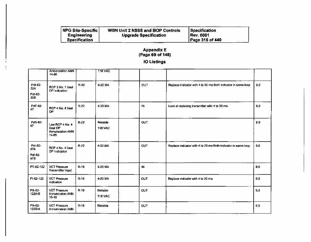
NPG Site-Specific WBN Unit 2 NSSS and BOP Controls SpecificationEngineering Upgrade Specification Rev. 0001Specification Page 315 of 440
Appendix E(Page 69 of 148)
10 Listings
Annunciation ANN 118 VAC14-86
Pdl-62- R-20 4-20 MA OUT Replace indicator with 4 to 20 ma Both indicator In same loop 9.032A RCP 3 No. 1 Seal
DP IndicationPdl-62-32B
PdT-62- R-22 4-20 MA IN Look at replacing transmitter with 4 to 20 ma 9.047 RCP 4 No- 4 Seal
DP
PdS.62- R-22 Bistable OUT 9.047 Low RCP 4 No- 4
Seal OP 118 VACAnnunciation ANN14-85
Pdl-62- R-22 4-20 MA OUT Replace indicator with 4 to 20 ma Both Indicator in same loop 9.047A RCP 4 No. 4 Seal
DP IndicationPdl-62-47B
PT-62-122 VCT Pressure R-19 4-20 MA IN 9.0Transmitter input
PI-62-122 VCT Pressure R-19 4-20 MA OUT Replace indicator with 4 to 20 ma 9.0Indication
PS-62- VCT Pressure R-19 Bistable OUT 9.0122AIB Annunication ANN
15-18 118 VAC
P"-62- VCT Pressure R-19 Bistable OUT 9.01228/A Annunication ANN
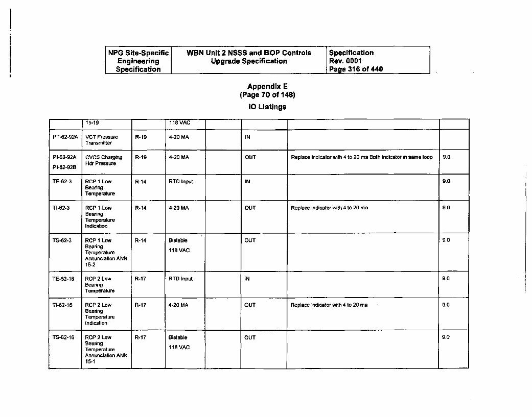
NPG Site-Specific WBN Unit 2 NSSS and BOP Controls SpecificationEngineering Upgrade Specification Rev. 0001Specification Page 316 of 440
Appemdix E(Page 70 of 148)
10 Listings
15-19 118 VAC
PT-62-92A VCT Pressure R-19 4-20 MA INTransmitter
PI-62-92A CVCS Charging R-19 4-20 MA OUT Replace indicator with 4 to 20 ma Both indicator in same loop 9.0
PI-62-92B Hdr Pressure
TE-62-3 RCP I Low R-14 RTD Input IN 9-0BearingTemperature
TI-62-3 RCP 1 Low R-14 4-20 MA OUT Replace indicator with 4 to 20 ma 9.0BearingTemperatureIndication
TS-62-3 RCP 1 Low R-14 Bistable OUT 9.0BearingTemperature 118 VAC
Annunciation ANN15-2
TE-52-16 RCP 2 Low R-17 RTD Input IN 9.0BearingTemperature
TI-62-16 RCP 2 Low R-17 4-20 MA OUT Replace indicator with 4 to 20 ma 9.0BearingTemperatureIndication
TS-62-16 RCP 2 Low R-17 Bistable OUT 9.0BearingTemperature 118 VACAnnunciation ANN15-1
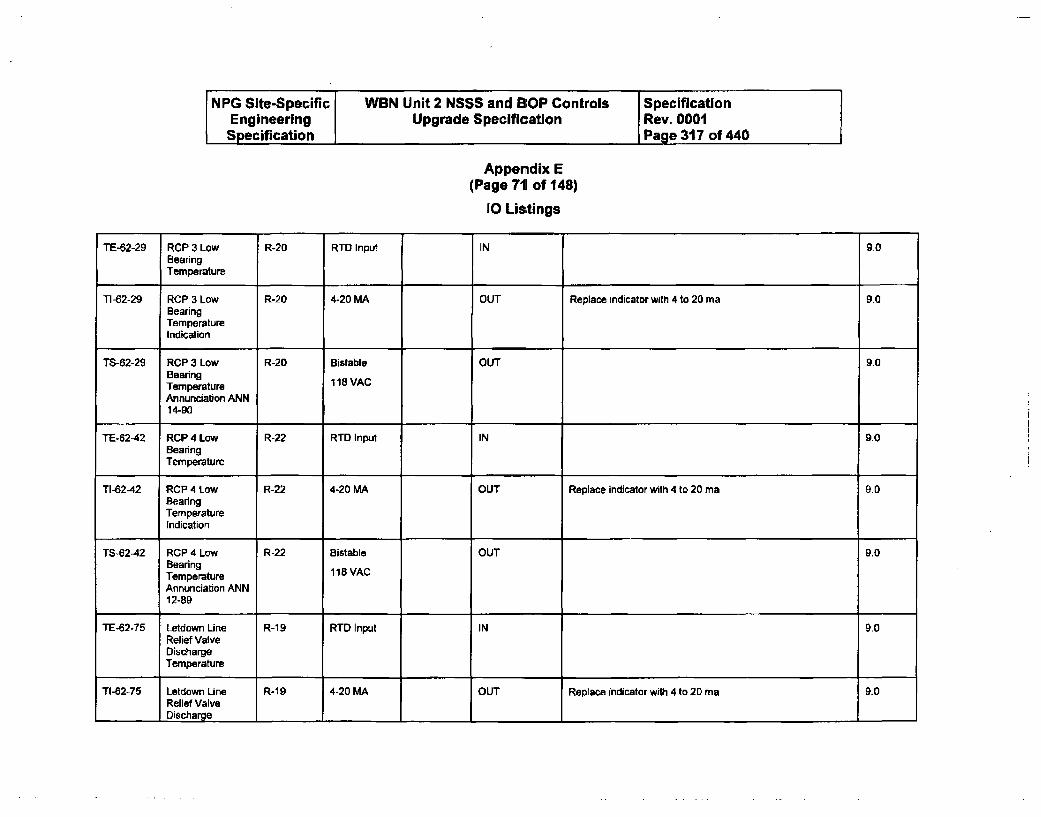
NPG Site-Specific WBN Unit 2 NSSS and S1OP Controls SpecificationEngineering Upgrade Specification Rev. 0001Specification Page 317 of 440 I
Appendix E(Page 711 of 148)
0 Listings
TE-62-29 RCP 3 Low R-20 RTD Input IN 9.0BearingTemperature
TI-62-29 RCP 3 Low R-20 4-20 MA OUT Replace indicator with 4 to 20 ma 9.0BearingTemperatureIndication
TS-62-29 RCP 3 Low R-20 Bistable OUT 9.0BearingTemperature 118 VACAnnunciation ANN14-90
TE-62-42 RCP 4 Low R-22 RTD Input IN 9.0BearingTemperature
TI-62-42 RCP 4 Low R-22 4-20 MA OUT Replace indicator with 4 to 20 ma 9.0BearingTemperatureIndication
TS-62-42 ROP 4 Low R-22 Bistable OUT 9.0BearingTemperature 118 VACAnnunciation ANN12-89
TE-62-75 Letdown Line R-19 RTD Input IN 9.0Relief ValveDischargeTemperature
TI-62-75 Letdown Line R-19 4-20 MA OUT Replace indicator with 4 to 20 ma 9.0Relief ValveDischarge I --I
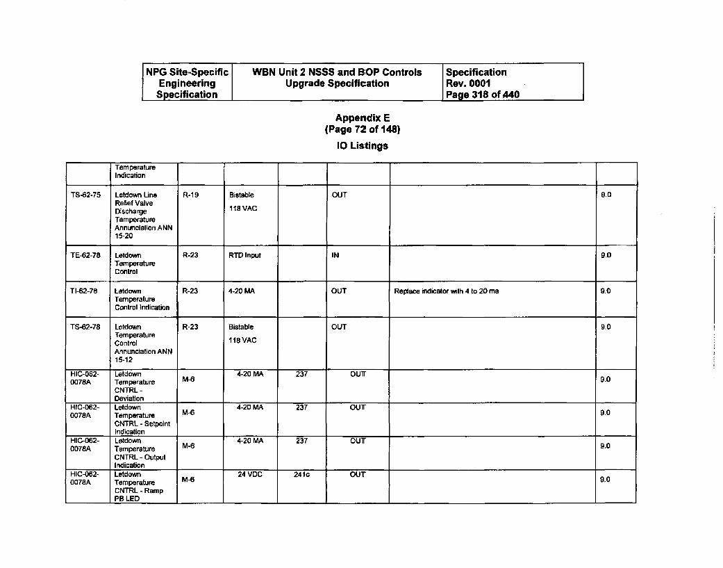
NPG Site-Specific WBN Unit 2 NSSS and BOP Controls SpecificationEngineering Upgrade Specification Rev. 0001
Specification Page 318 of 440
Appendix E(Page 72 of 148)
10 Listings
TemperatureIndication
TS-62-75 Letdown Line R-19 Bistable OUT g.0Relief ValveDischarge 118 VAC
TemperatureAnnunciation ANN15-20
TE-62-78 Letdown R-23 RTD' Input IN 9.0TemperatureControl
TI-62-78 Letdown R-23 4-20 MA OUT Replace indicator with 4 to 20 ma 9.0TemperatureControl Indication
TS-62-78 Letdown R-23 Bistable OUT 9.0TemperatureControl 118VACAnnunciation ANN15-12
HIC-062- Letdown 4-20 MA 237 OUT0078A Temperature M-6 9.0
CNTRL -Deviation
HIC-062- Letdown 4-20 MA 237 OUT0078A Temperature M-6 9.0
CNTRL - SetpointIndication
HIC-062- Letdown 4-20 MA 237 OUT0078A Temperature M-6 9.0
CNTRL - OutputIndication
HIC-062- Letdown 24 VDC 241c OUT0078A Temperature M6 9,0
CNTRL - RampPB LED I
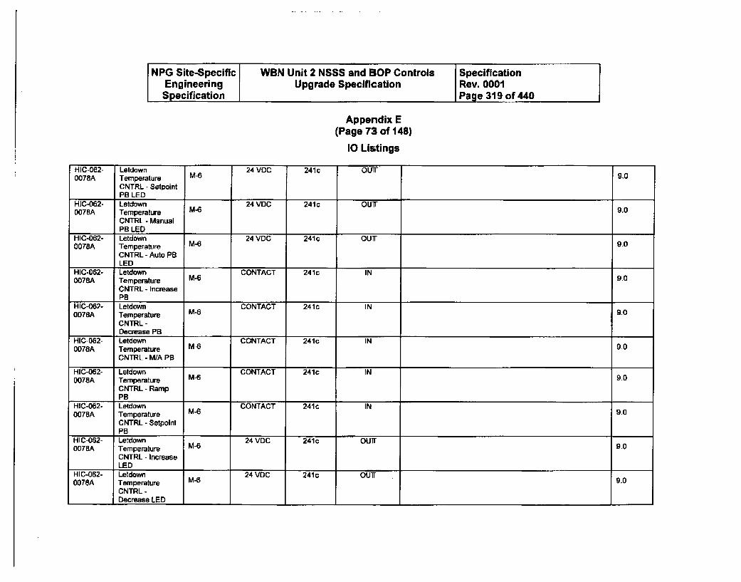
NPG Site-Specific WBN Unit 2 NSSS and BOP Controls SpecificationEngineering Upgrade Specification Rev. 0001Specification Page 319 of 440
Appendix E(Page 73 of 148)
10 Listings
HIC-062- Letdown 24 VOC 241c OUT0078A Temperature M-6 9.0
CNTRL - SetpointPB LED
HIC-062- Letdown 24 VDC 241c OUT0078A Temperature M-6 9.0
CNTRL - ManualPB LED
HIC-062- Letdown 24 VDC 241c OUT0078A Temperature M-6 9.0
CNTRL - Auto PBLED
HIC-062- Letdown CONTACT 241c IN0078A Temperature M-6 9.0
CNTRL - IncreasePB
HIC-062- Letdown CONTACT 241C IN0078A Temperature M-6 9.0
CNTRL-Decrease PB
HIC-062- Letdown CONTACT 241c IN0078A Temperature M-6 9.0
CNTRL - MWA PB
HIC-062- Letdown CONTACT 241c IN0078A Temperature M-6 9.0
CNTRL - RampPB
HIC-062- Letdown CONTACT 241c IN0078A Temperature M-6 9.0
CNTRL - SetpolntPB
HIC-062- Letdown 24 VDC 241c OUT0078A Temperature M-6 9.0
CNTRL - IncreaseLEDI
HIC-062- Letdown 24 VDC 241c OUTr0078A Temperature M-6 9.0
CNTRL -Decrease LED
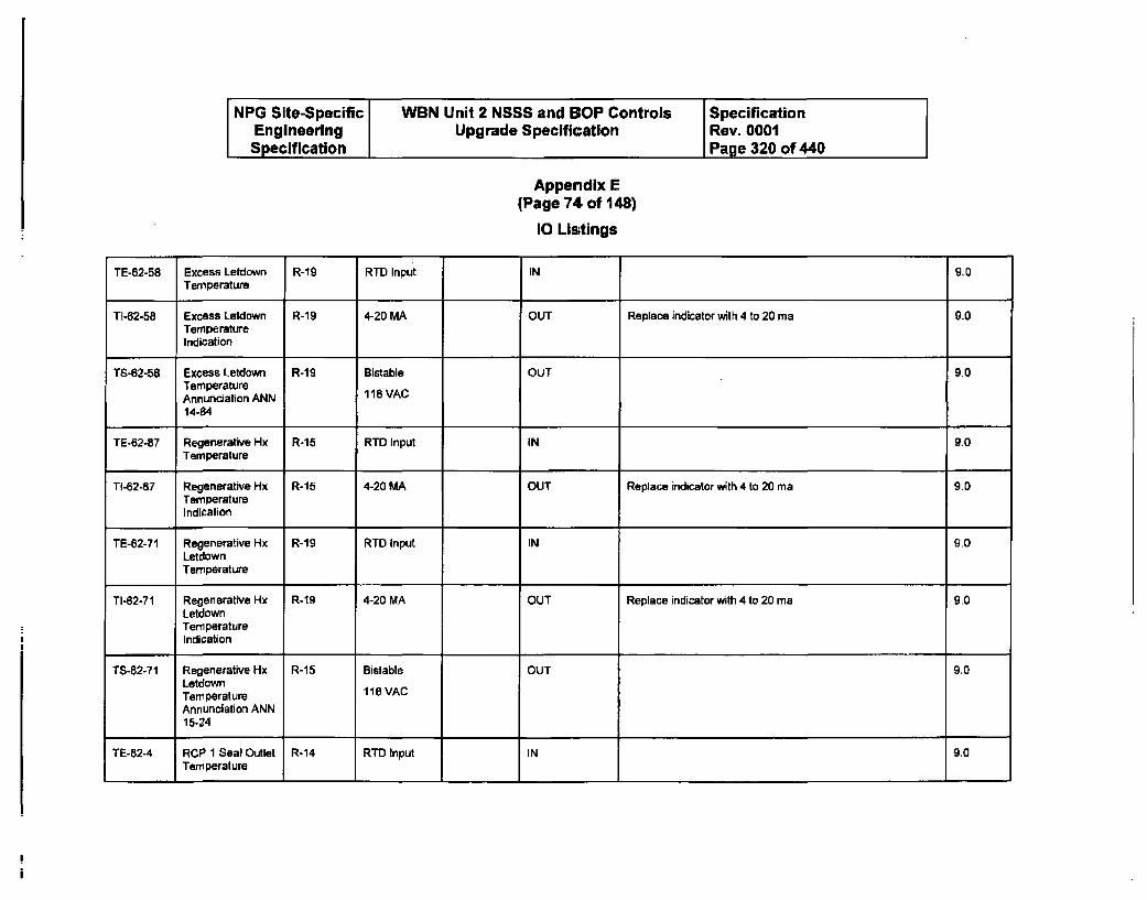
NPG Site-Specific WBN Unit 2 NSSS and BOP Controls SpecificationEngineering Upgrade Specification Rev. 0001Specification Page 320 of 440
Appendix E(Page 74 of 148)
10 Listings
TE-62-58 Excess Letdown R-19 RTD Input IN 9.0Temperature
TI-62-58 Excess Letdown R-19 4-20 MA OUT Replace indicator with 4 to 20 ma 9.0TemperatureIndication
TS-62-58 Excess Letdown R-19 Bistable OUT 9.0TemperatureAnnunciation ANN 118 VAC
14-84
TE-62-87 Regenerative Hx R-15 RTD Input IN 9.0Temperature
TI-62-87 Regenerative Hx R-15 4-20 MA OUT Replace indicator with 4 to 20 ma 9D0TemperatureIndication
TE-62-71 Regenerative Hx R-19 RTD Input IN 9.0LetdownTemperature
TI-62-71 Regenerative Hx R-19 4-20 MA OUT Replace indicator with 4 to 20 ma 9.0LetdownTemperatureIndication
TS-82-71 Regenerative Hx R-15 Bistable OUT 9.0LetdownTemperature 118 VAC
Annunciation ANN15-24
TE-62-4 RCP 1 Seal Outlet R-14 RT'D Input IN 9.0Temperature
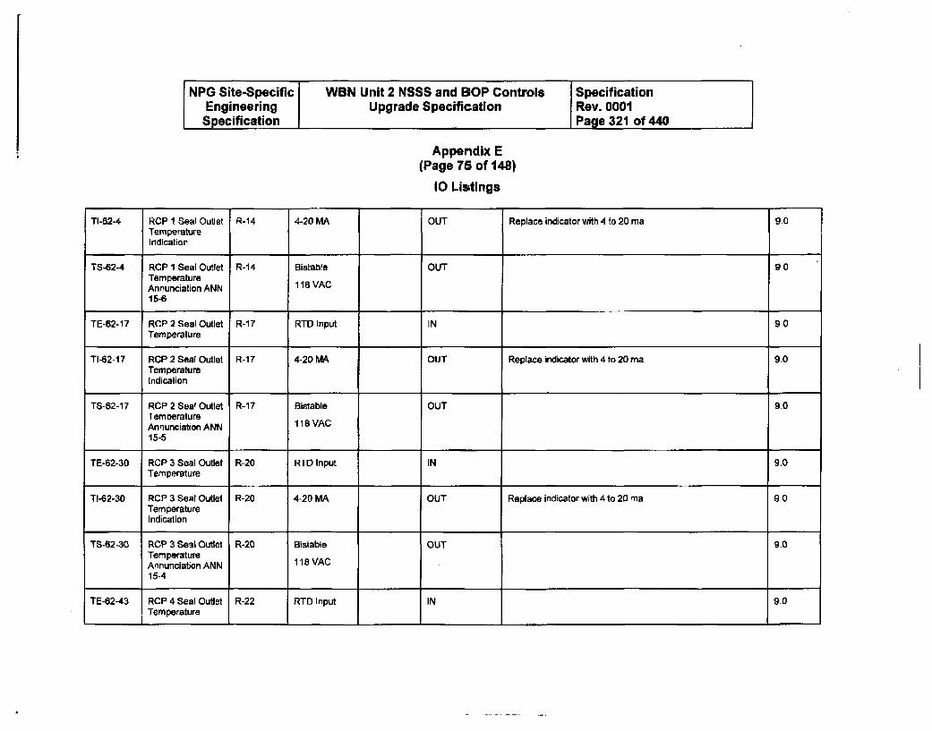
NPG Site-Specific WBN Unit 2 NSSS and BOP Controls SpecificationEngineering Upgrade Specification Rev. 0001
Specification Page 321 of 440
Appendix E(Page 75 of 148)
10 Listings
TI-62-4 RCP I Seal Outlet R-14 4-20 MA OUT Replace indicator with 4 to 20 ma 9.0TemperatureIndication
TS-62-4 RCP 1 Seal Outlet R-14 Bistable OUT 9.0TemperatureAnnunciation ANN 118 VAC15-6
TE-62-17 RCP 2 Seal Outlet R-17 RID Input IN 90Temperature
TI-62-17 RCP2SeaI Outlet R-17 4-20 MA OUT Replace indicator with 4 to 20 ma 9.0TemperatureIndication
TS-62-17 RCP 2 Seal Outlet R-17 Bistable OUT 9.0TemperatureAnnunciation ANN 118 VAC15-5
TE-62-30 RCP 3 Seal Outlet R-20 RTO Input IN 9.0Temperature
TI-62-30 RCP 3 Seal Outlet R-20 4-20 MA OUT Replace indicator with 4 to 20 ma 9.0TemperatureIndication
TS-62-30 RCP 3 Seal Outlet R-20 Bistable OUT 9.0TemperatureAnnunciation ANN 118 VAC15-4
TE-62-43 RCP 4 Seal Outlet R-22 RTD Input IN 9.0Temperature
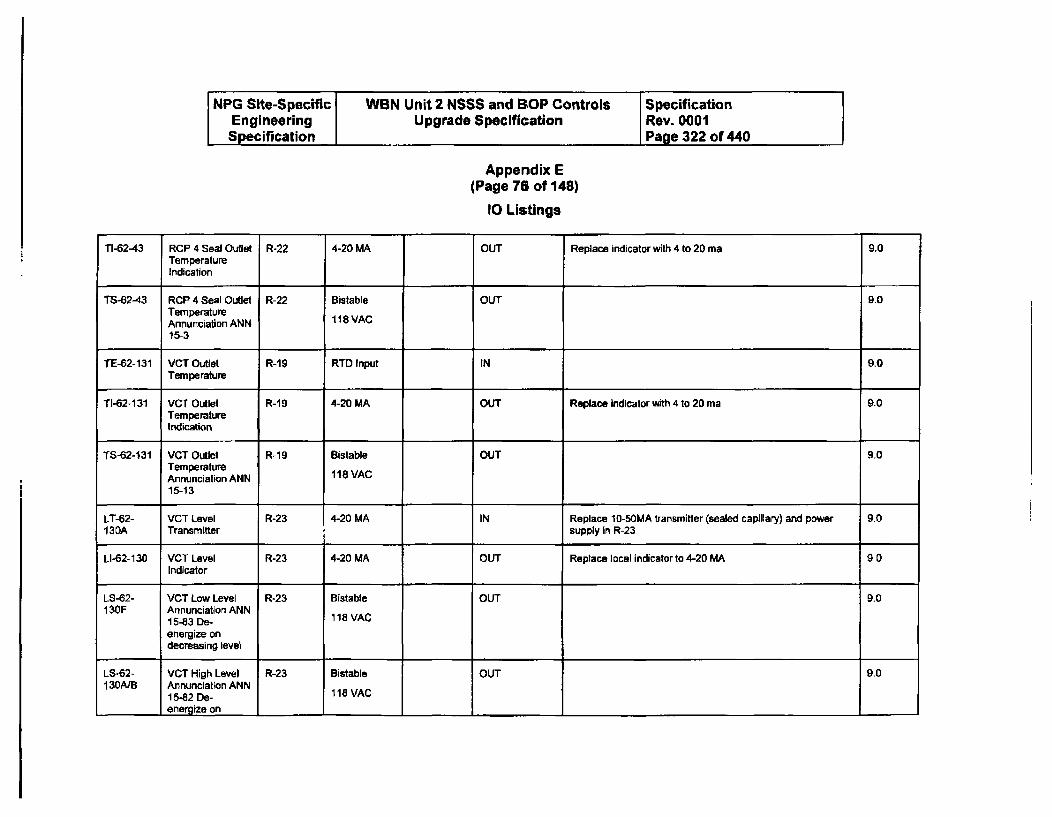
NPG Site-Specific WBN Unit 2 NSSS and BOP Controls SpecificationEngineering Upgrade Specification Rev. 0001Specification Page 322 of 440
Appendix E(Page 76 of 148)
1O Listings
TI-62-43 RCP 4 Seal Outlet R-22 4-20 MA OUT Replace indicator with 4 to 20 ma 9.0TemperatureIndication
TS-62-43 RCP 4 Seal Outlet R-22 Bistable OUT 9.0TemperatureAnnunciation ANN 118 VAC
15-3
TE-62-131 VCT Outlet R-19 RTD Input IN 9-0Temperature
TI-62-131 VCT Outlet R-19 4-20 MA OUT Replace indicator with 4 to 20 ma 9.0TemperatureIndication
TS-62-131 VCT Outlet R-19 Bistable OUT 9.0TemperatureAnnunciation ANN 118 VAC
15-13
LT-62- VCT Level R-23 4-20 MA IN Replace 10-50MA transmitter (sealed capillary) and power 9.0130A Transmitter supply in R-23
LI-62-130 VCT Level R-23 4-20 MA OUT Replace local indicator to 4-20 MA 9.0Indicator
LS-62- VCT Low Level R-23 Bistable OUT 9.0130F Annunciation ANN
15-3 De- 118 VAC
energize ondecreasing level
LS-62- VCT High Level R-23 Bistable OUT 9.0130A/B Annunciation ANN
15-82 De- 118 VACenergize on I I
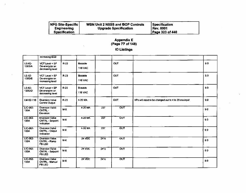
NPG Site-Specific WBN Unit 2 NSSS and BOP Controls SpecificationEngineering Upgrade Specification Rev. 0001Specification Page 323 of 440
Appendix E(Page 77 of 148)
10 Listings
increasing level
LS-62- VCT Level < SP R-23 Bistable OUT 90130B/A De-energize on
decreasing level 118 VAC
LS-62- VCT Level > SP R-23 Bistable OUT 9.0130DIE De-energize on
increasing level 118 VAC
LS-62- VCT Level < SP R-23 BistabWe OUT 9.0130E/D De-energize on
decreasing level 118 VAC
LM-62-118 Diversion Valve R-23 4-20 MA OUT I/Ps will need to be changed out to 4 to 20 ma input 9.0Control Output
LIC-062- Diversion Valve 4-20 MA 237 OUT130A CNTRL - M-6 90
Deviation
LIC-062- Diversion Valve 4-20 MA 237 OUT130A CNTRL - Setpoint M-6 90
Indication
LIC-062- Diversion Valve 4-20 MA 237 OUT130A CNTRL - Output M- 90
Indication
LIC-062- Diversion Valve 24 VDC 241c OUT130A CNTRL-Ramp M-6 90
PB LED
LIC-062- Diversion Valve 24 VDC 241c OUT130A CNTRL - Setpoint M-6 9.0
PB LED
LIC-062. Diversion Valve 24 VDC 241c OU9.0130A CNTRL -Manual M- 2o
PB LED
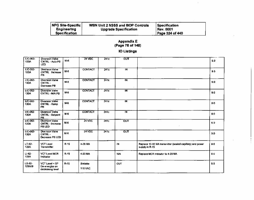
NPG Site-Specific WBN Unit 2 NSSS and BOP Controls SpecificationEngineering Upgrade Specification Rev. 0001Specification Page 324 of 440
Appemdix E
(Page 78 of 148)
10 Listings
UC-062- Diversion Valve 24 VDC 241c OUT130A CNTRL - Auto PB M-6 9.0
LED
LIC-062- Diversion Valve CONTACT 241c IN130A CNTRL - Increase M-6 90
PB
LIC-062- Diversion Valve CONTACT 241c IN130A CNTRL - M-6 9.0
Decrease PB
LIC-062- Diversion Valve CONTACT 241 c IN130A CNTRL - M/A PB M-6 9.0
LIC-062- Diversion Valve CONTACT 241 IN130A CNTRL - Ramp M-6 9.0
PB
LIC-062- Diversion Valve CONTACT 241 c IN130A CNTRL - Setpoint M-6 9.0
PB
LIC-062- Diversion Valve 24 VDC 241c OUT130A CNTRL - Increase M-6 9.0
PB LED
LIC-062- Diversion Valve 24 VDC 241c OUT130A CNTRL- M-6 9.0
Decrease PR LED
LT-62- VCT Level R-15 4-20 MA IN Replace 10-50 MA transmitter (sealed capillary) and power 9.0129A Transmitter supply in R-1 5
LI-62- VCT Level MCR R-15 4-20 MA N/A Replace MCR indicator to 4-20 MA 9.0129A Indicator
LS-62- VCT Level c SP R-15 Bistable OUT 9.0129AJB De-energize on
decreasing level 118 VAC
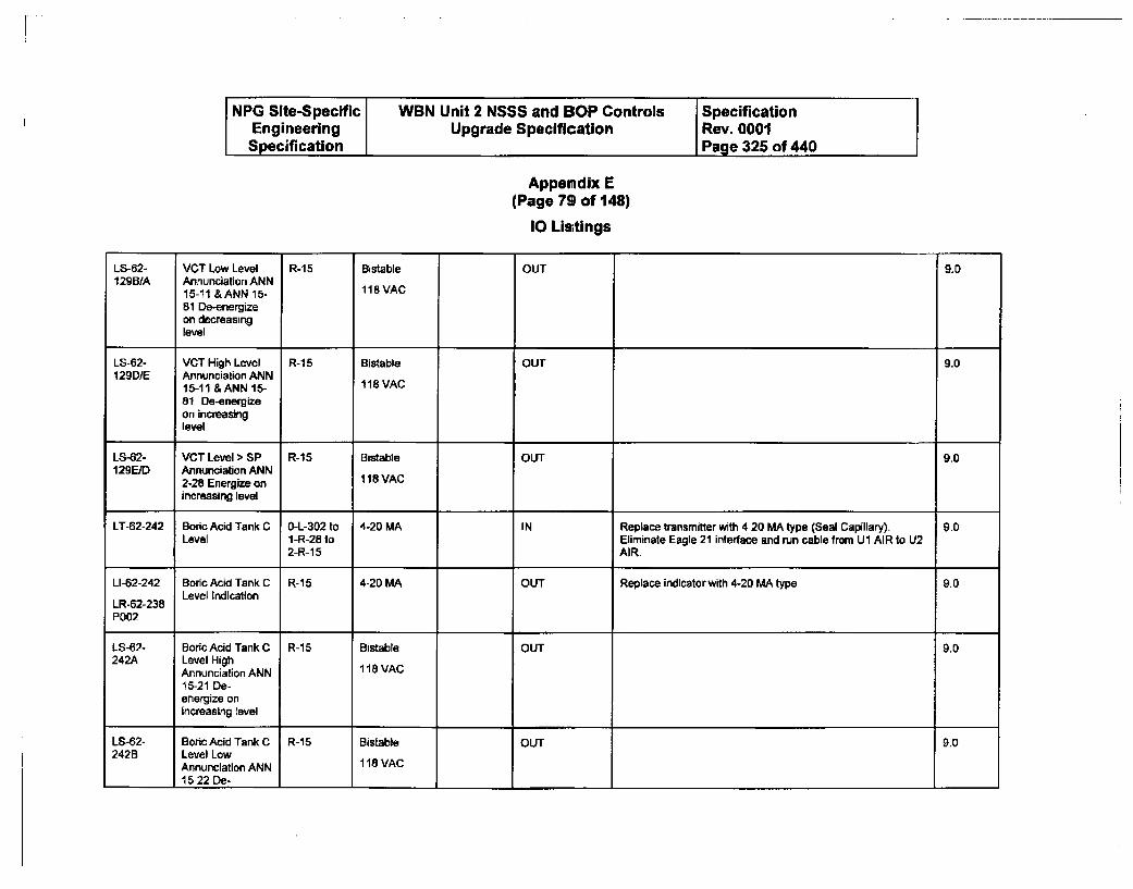
NPG Site-Specific WBN Unit 2 NSSS and SOP Controls SpecificationEngineering Upgrade Specification Rev. 0001Specification Page 325 of 440
Appendix E(Page 79 of 148)
10 Listings
LS-62- VCT Low Level R-15 Bistable OUT 9.0129BIA Annunciation ANN
15-11 &ANN 15- 118VAC81 De-energizeon decreasinglevel
LS-"2- VCT High Level R-15 Bistable OUT 9.0129DIE Annunciation ANN
15-11 &ANN 15- 118 VAC81 De-energizeon increasinglevel
LS-62- VCT Level > SP R-15 Bistable OUT 9.0129E/D Annunciation ANN
2-28 Energize on 118 VAC
increasing level
LT-62-242 Boric Acid Tank C O-L-302 to 4-20 MA IN Replace transmitter with 4-20 MA type (Seal Capillary). 9.0Level 1-R-28 to Eliminate Eagle 21 interface and run cable from UI AIR to U2
2-R-15 AIR.
LI-62-242 Boric Acid Tank C R-15 4-20 MA OUT Replace indicator with 4-20 MA type 9.0Level IndicationLR-62-238
P002
LS-62- Boric Acid Tank C R-1 5 Bistable OUT 9.0242A Level High
Annunciation ANN 118 VAC15-21 De-energize onincreasing level
LS-62- Boric Acid Tank C R-15 Bistable OUT 9.0242B Level Low
Annunciation ANN 118 VAC15-22 De- I

NPG Site-Specific WBN Unit 2 NSSS and 1OP Controls SpecificationEngineering Upgrade Specification Rev. 0001Specification Page 326 of 440
Appendix E(Page 80 of 148)
10 Listings
energize ondecreasing level
LT.62-238 Boric Acid Tank B L-301 to R- 4-20 MA IN Replace transmiller with 4-20 MA type (Seal Capillary). 9.0Level 3 to R-21 Eliminate Eagle 21 interface.
LI-62-238 Boric Acid Tank B R-21 4-20 MA OUT Replace indicator with 4-20 MA type 9.0Level IndicationLR-62-238
Pool
LS-62- Boric Acid Tank B R-21 Bistable OUT 9.0238A Level High
Annunciation ANN 118 VAC
15-74 De-energize onincreasing level
LS-62- Boric Acid Tank B R-21 Bistable OUT 9.0238B Level Low
Annunciation ANN 118 VAC15-75 De-energize ondecreasing level
FT-62-10 RCP No. 1 Seal R-14 4-20 MA IN 9.0Low RangeLeakoff FlowTransmitter
FS-62-10 RCP No. 1 Seal R-14 Bistable OUT 9.0Low RangeLeakfolf Flow 118 VACTransmitterAnnunciation ANN14-75
FT-62-11 RCP No. 1 Seal R-14 4-20 MA IN 9.0-_ I High Range I I I I I
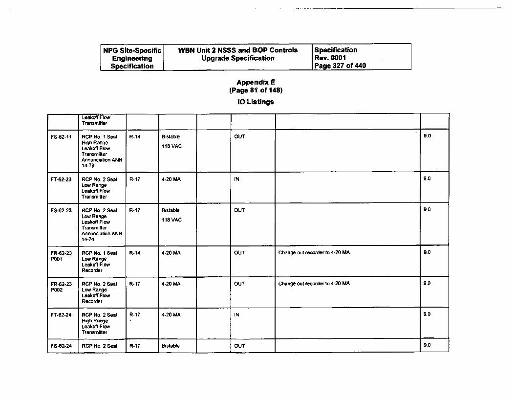
[ NPG Site-Specific WBN Unit 2 NSSS and BSOP Controls SpecificationEngineering Upgrade Specification Rev. 0001Specification Page 327 of 440
Appendix E(Page 811 of 148)
10 Listings
Leakoff FlowTransmitter
FS-62-11 RCP No. I Seal R-14 Bistable OUT 9.0High RangeLeakoff Flow 1 18 VAC
TransmitterAnnunciation ANN14-79
FT-62-23 RCP No. 2 Seal R-17 4-20 MA IN 9.0Low RangeLeakoff FlowTransmitter
FS-62-23 RCP No. 2 Seal R-17 Bistable OUT 9.0Low RangeLeakoff Flow 118 VACTransmitterAnnunciation ANN14-74
FR-62-23 RCP No. 1 Seal R-14 4-20 MA OUT Change out recorder to 4-20 MA 9.0POOl Low Range
Leakoff FlowRecorder
FR-62-23 RCP No. 2 Seal R-17 4-20 MA OUT Change out recorder to 4-20 MA 9.0P002 Low Range
Leakoff FlowRecorder
FT-62-24 RCP No. 2 Seal R-17 4-20 MA IN 9.0High RangeLeakoff FlowTransmitter
FS-62-24 RCP No. 2 Seal R-17 Bistable OUT 9.0
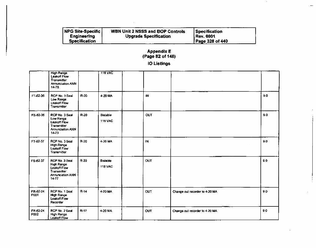
NPG Site-Specific WBN Unit 2 NSSS and 1OP Controls SpecificationEngineering Upgrade Specification Rev. 0001Specification Page 328 of 440
Appendix E(Page 82 of 148)
10 Listings
High Range 118 VACLeakoff FlowTransmitterAnnunciation ANN14-78
FT-62-36 RCP No. 3 Seal R-20 4-20 MA IN 9.0Low RangeLeakoff FlowTransmitter
FS-62-36 RCP No. 3 Seal R-20 Bistable OUT 9-0Low RangeLeakoff Flow 118 VACTransmitterAnnunciation ANN14-73
FT-62-37 RCP No. 3 Seal R-20 4-20 MA IN 9.0High RangeLeakoff FlowTransmitter
FS-62-37 RCP No 3 Seal R-20 Bistable OUT 9.0High RangeLeakoff Flow 118 VAC
TransmitterAnnunciation ANN14-77
FR-62-24 RCP No. 1 Seal R-14 4-20 MA OUT Change out recorder to 4-20 MA 90POOl High Range
Leakoff FlowRecorder
FR-62-24 RCP No. 2 Seal R-17 4-20 MA OUT Change out recorder to 4-20 MA 9.0P002 High Range
Leakoff Flow I

NPG Site-Specific WBN Unit 2 NSSS and BOP Controls SpecificationEngineering Upgrade Specification Rev. 0001Specification Page 329 of 440
Appendix E(Page 83 of 148)
10 Listings
Recorder
FT-62-49 RCP No. 4 Seal R-22 4-20 MA IN 9.0Low RangeLeakoff FlowTransmitter
FS-62-49 RCP No. 4 Seal R-22 Bistable OUT 9.0Low RangeLeakoff Flow 118 VAC
TransmitterAnnunciation ANN14-72
FR-62-49 RCP No. 3 Seal R-20 4-20 MA OUT Change out recorder to 4-20 MA 9.0Pool Low Range
Leakoff FlowRecorder
FT-62-50 RCP No. 4 Seal R-22 4-20 MA IN 9.0High RangeLeakoff FlowTransmitter
FS-62-50 RCP No. 4 Seal R-22 Bistable OUT 9.0High RangeLeakoff Flow 118 VAC
TransmitterAnnunciation ANN14-76
FR-62-49 RCP No. 4 Seal R-22 4-20 MA OUT Change out recorder to 4-20 MA 9.0P002 Low Range
Leakoff FlowRecorder
FR-62-50 RCP No. 3 Seal R-20 4-20 MA OUT Change out recorder to 4-20 MA 9.0P001 High Range
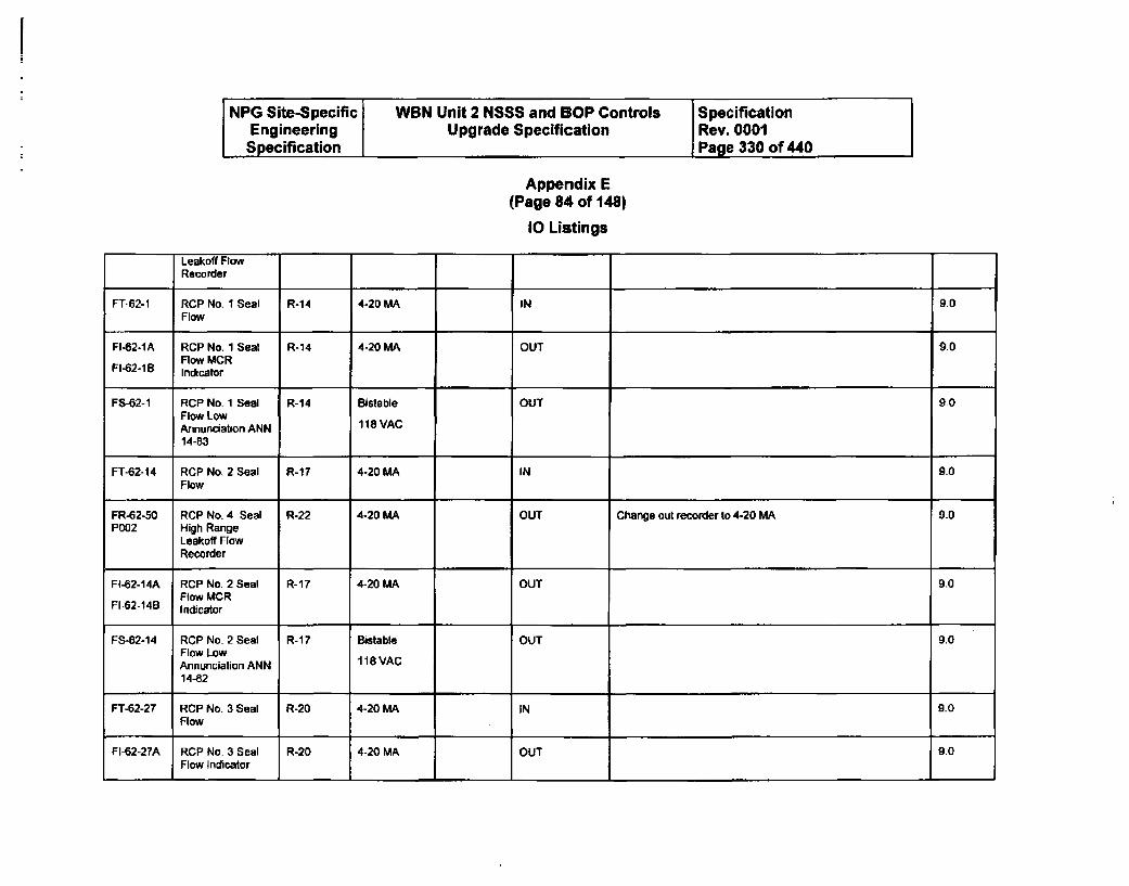
NPG Site-Specific WBN Unit 2 NSSS and BOP Controls SpecificationEngineering Upgrade Specification Rev. 0001Specification Page 330 of 440
Appendix E(Page 84 of 148)
10 Listings
Leakoff FlowRecorder
FT-62-1 RCP No. I Seal R-14 4-20 MA IN 9.0Flow
FI-62-IA RCP No. 1 Seal R-14 4-20 MA OUT 90Flow MCR
FI-62-1 B Indicator
FS-62-1 RCP No. 1 Seal R-14 Bistable OUT 9.0Flow LowAnnunciation ANN 118 VAC
14-83
FT-62-14 RCP No. 2 Seal R-17 4-20 MA IN 90Flow
FR-62-50 RCP No. 4 Seal R-22 4-20 MA OUT Change out recorder to 4-20 MA 90P002 High Range
Leakoff FlowRecorder
FI-62-14A RCP No. 2 Seal R-17 4-20 MA OUT 9.0Flow MCR
FI-62-14B Indicator
FS-62-14 RCP No- 2 Seal R-17 Bistable OUT 90Flow LowAnnunciation ANN 118 VAC
14-82
FT-62-27 RCP No. 3 Seal R-20 4-20 MA IN 9.0Flow
FI-62-27A RCP No. 3 Seal R-20 4-20 MA OUT 9.0Flow Indicator
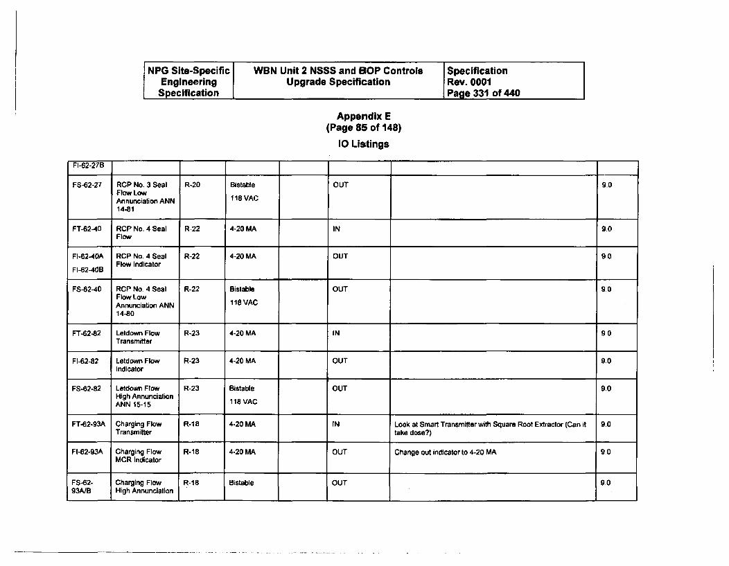
NPG Site-Specific WBN Unit 2 NSSS and SOP Controls SpecificationEngineering Upgrade Specification Rev. 0001Specification I Page 331 of 440
Appendix E(Page 85 of 148)
10 Listings
FI-62-27B
FS-62-27 RCP No. 3 Seal R-20 Bistable OUT 9.0Flow LowAnnunciation ANN 118 VAC14-81
FT-62-40 RCP No. 4 Seal R-22 4-20 MA IN 9.0Flow
FI-62-40A RCP No. 4 Seal R-22 4-20 MA OUT 9,0Flow Indicator
FI-62-40B
FS-62-40 RCP No. 4 Seal R-22 Bistable OUT 9.0Flow LowAnnunciation ANN 118 VAC14-80
FT-62-82 Letdown Flow R-23 4-20 MA IN 9.0Transmitter
FI-62-82 Letdown Flow R-23 4-20 MA OUT 90Indicator
FS-62-82 Letdown Flow R-23 Bistable OUT 9.0High AnnunciationANN 15-15 118 VAC
FT-62-93A Charging Flow R-1 8 4-20 MA IN Look at Smart Transmitter with Square Root Extractor (Can it 9.0Transmitter take dose?)
FI-62-93A Charging Flow R-18 4-20 MA OUT Change out indicator to 4-20 MA 9.0MCR Indicator
FS-62- Charging Flow R-18 Bistable OUT 9093A/B High Annunciation
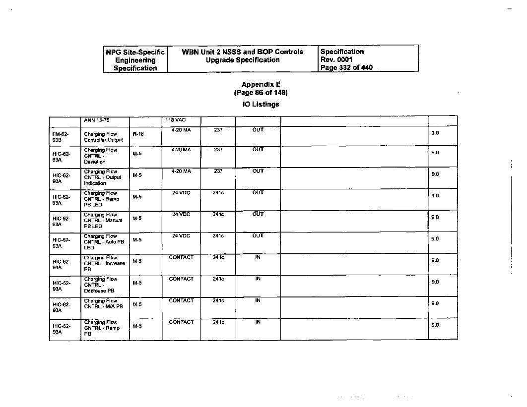
NPG Site-Specific WBN Unit 2 NSSS and BOP Controls SpecificationEngineering Upgrade Specification Rev. 0001Specification Page 332 of 440
Appendix E(Page 86 of 148)
10 Listings
ANN 15-76 118iVAC4-20 MA 237 OUIT
FM-62- Charging Flow R-18 9.093B Controller Output
H1C42 Charging Flow 4-20 MA 237 OUT 9.0CNTRL - M-593A Deviation
Charging Flow 4-20 MA 237 OUTH1C-42- CNTRL - Output M- 9.093A Indication
Charging Flow 24 VDC 241c OUT 0HIC-62- CNTRL - Ramp M5 9.093A PB LED
Charging Flow 24 VDC 241c OUT I0NIC-62- CNTRL - Manual M5 9093A PBRLED
Charging Flow 24 VDC 241c OUTHIC-42- CNTRL - Auto PB M5 9093.A LED
Charging Flow CONTACT 241c INHIC-42- CNTRL - Increase M5 9093A PB
Charging Flow CONTACT 241c INHIC-62- CNTRL - M-5 9.0W3A Decrease PB
Charging Flow CONTACT 241c IN 9HIC-62- CNTRL - MIA PB M-5 9093A
Charging Flow CONTACT 241c INHIC-62- CNTRL - Ramp M-5 9.093A PB
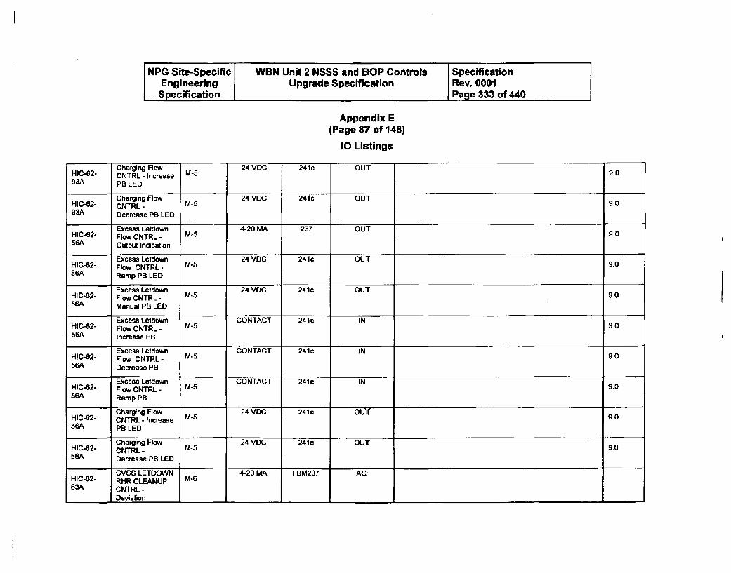
NPG Site-Specific WBN Unit 2 NSSS and SOP Controls SpecificationEngineering Upgrade Specification Rev. 0001Specification Page 333 of 440
Appendix E(Page 87 of 148)
10 Listings
Charging Flow 24 VDC, 241 c OUITHIC-62- CNTRL - Increase M-5 9.093A PB LED
Charging Flow 24 VEX0 241c OUTHIC-62- CNTRL - M-5 9093A Decrease PB LED
Excess Letdown 4-20 MA 237 OUT 9.0HICo2- Flaw CNTRL -56A Output Indication
Excess Letdown 24 VDC 241c OUTHIC-62- Flow CNTRL - M-5 9.056A Ramp PB LED
Excess Letdown 24 VDC 241c OUTHIC-62- Flow CNTRL - M-5 9.056A Manual PB LED
Excess Letdown CONTACT 241c INHI10-62- Flow CNTRL - M-5 9056A Increase PB
Excess Letdown CONTACT 241c IN 90HIC-82- Flow CNTRL- M-556A Decrease PB
Excess Letdown CONTACT 241c INHIC-82- Flow CNTRL - M5 9.056A Ramp PB
Charging Flow 24 VDC' 241c OUTHIC-62- CNTRL - Increase M5 9.056A PB LED
Charging Flow 24 VDC' 241 c OUT
HIC-e2- CNTRL - M-5 9.056A Decrease PB LED
CVCS LETDOWN 4-20 MA FBM237 AOHIC-82- RHR CLEANUP M-683A CNTRL -
_ Deviation
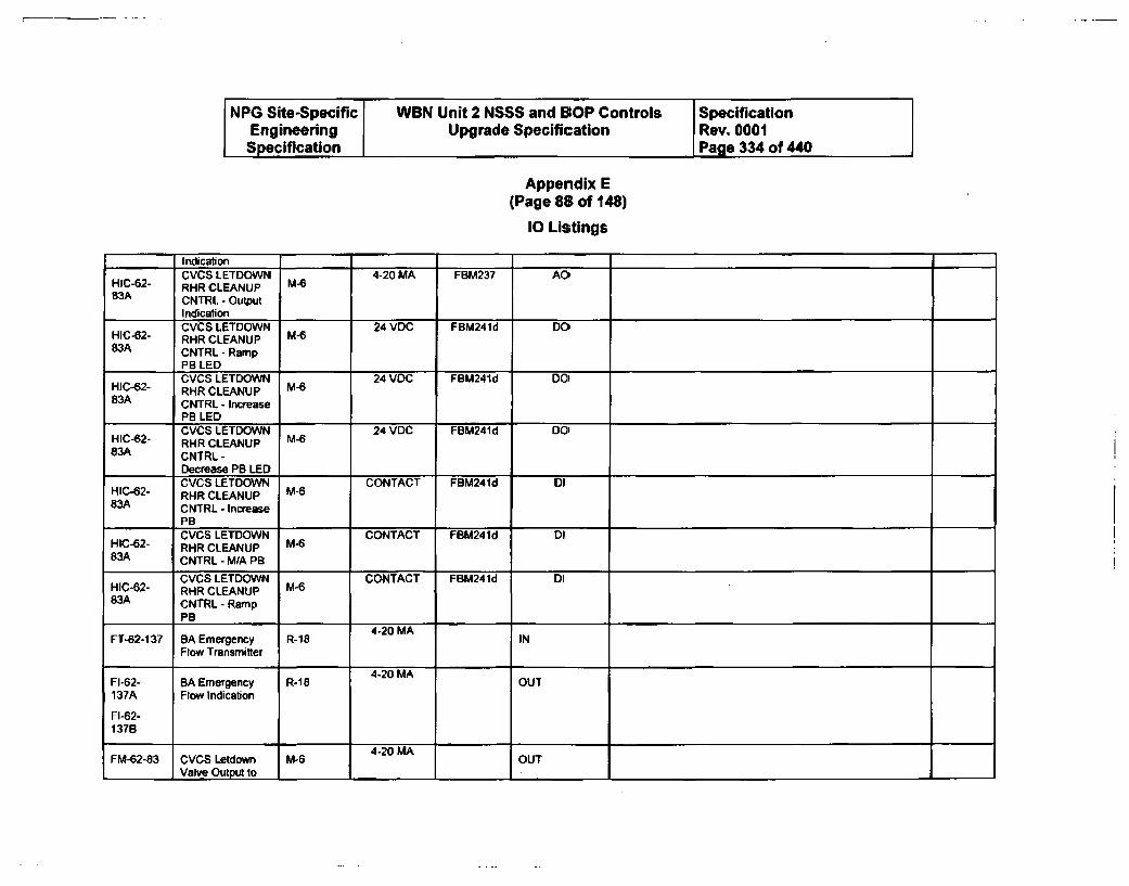
NPG Site-Specific WBN Unit 2 NSSS and BOP Controls SpecificationEngineering Upgrade Specification Rev. 0001Specification Page 334 of 440
Appendix E(Page 88 of 148)
10 Listings
IndicationCVCS LETDOWN 4-20 MA FBM237 AOG
HIC0-62- RHR CLEANUP M-683A CNTRL - Output
IndicationCVCS LETDOWN 24 VDC FBM241d DO'
HIC-62- RHR CLEANUP M-683A CNTRL-Ramp
PB LEDCVCS LETDOWN 24 VOC FBM241d DO'
HIC-82- RHR CLEANUP M-683A CNTRL - Increase
PB LEDCVCS LETDOWN 24 VDC FBM241d DO)
HIC-82- R4HR CLEANUP M-683A CNTRL-
Decrease PB LEDCVCS LETDOWN CONTACT FBM241d DI
HIC-62- RHR CLEANUP M-683A CNTRL - Increase
PBCVCS LETDOWN CONTACT FBM241d DI
HIC-82- RHR CLEANUP MC T83A CNTRL - M/A PB
CVCS LETDOWN CONTACT FBM241d DIHIC-82- RHR CLEANUP M-683A CNTRL-Ramp
IPB
FT-62-137 BA Emergency R-18 4-20 MA INFlow Transmitter
4-20 MAFI-62- BA Emergency R-18 OUT137A Flow Indication
FI-62-137B
4-20 MAFM-62-83 CVCS Letdown M-6 OUT
I Valve Output to I I . I L I
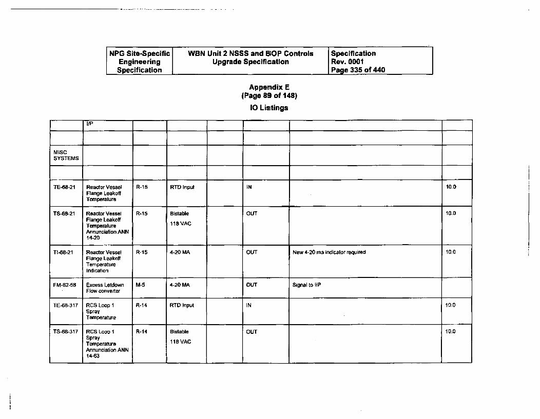
NPG Site-Specific WBN Unit 2 NSSS and BlOP Controls SpecificationEngineering Upgrade Specification Rev. 0001Specification Page 335 of 440
Appendix E(Page 89 of 148)
10 Listings
tiP
MISCSYSTEMS
TE-68-21 Reactor Vessel R-15 RTD Input IN 10.0Flange LeakoffTemperature
TS-68-21 Reactor Vessel R-15 Bistable OUT 10.0Flange LeakoffTemperature 118 VAC
Annunciation ANN14-20
TI-68-21 Reactor Vessel R-15 4-20 MA OUT New 4-20 ma indicator required 10.0Flange LeakoffTemperatureIndication
FM-62-56 Excess Letdown M-5 4-20 MA OUT Signal to i/PFlow converter
TE-68-317 RCS Loop 1 R-14 RTD Input IN 10.0SprayTemperature
TS-68-317 RCS Loop 1 R-14 Bistable OUT 10.0SprayTemperature 118 VAC
Annunciation ANN14-63
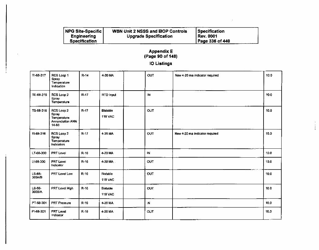
NPG Site-Specific WBN Unit 2 NSSS and BOP Controls SpecificationEngineering Upgrade Specification Rev. 0001Specification Page 336 of 440 j
Appendix E(Page 90 of 148)
10 Listings
TI-68-317 RCS Loop 1 R-14 4-20 MA OUT New 4-20 ma indicator required 10.0SprayTemperatureIndication
TE-6B-316 RCS Loop 2 R-17 RTD Input IN 10.0SprayTemperature
TS-68-316 RCS Loop 2 R-17 Bistable OUT 10.0SprayTemperature 118 VAC
Annunciation ANN14-63
TI-68-316 RCS Loop 2 R-17 4-20 MA OUT New 4-20 ma indicator required 1010SprayTemperatureIndication
LT-68-300 PRT Level R-16 4-20 MA IN 10.0
LI-68-300 PRT Level R-1 6 4-20 MA OUT 10.0Indicator
LS-68- PRT Level Low R-16 Bistable OUT 10.0300A/B
118 VAC
LS-68- PRT Level High R-i6 Bistable OUT 10.0300B/A
118VAC
PT-68-301 PRT Pressure R-16 4-20 MA IN 10.0
PI-68-301 PRT Level R-16 4-20 MA OUT 10.0Indicator
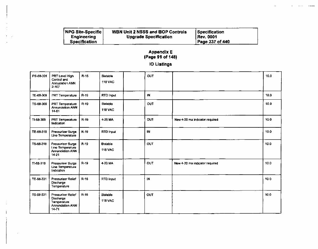
NPG Site-Specific WBN Unit 2 NSSS and BOP Controls SpecificationEngineering Upgrade Specification Rev. 0001Specification Page 337 of 440
Appendix E(Page 911 of 148)
10 Listings
PS-68-301 PRT Level High R-16 Bistable OUT 10.0Control andAnnuciation ANN 118 VAC
2-107
TE-68-309 PRT Temperature R-19 RTD Input IN 10.0
TS-68-309 PRT Temperature R-19 Bistable OUT 10.0Annunciation ANN14-61 118 VAC
TI-68-309 PRT Temperature R-19 4-20 MA OUT New 4-20 ma indicator required 10.0Indication
TE-68-318 Pressurizer Surge R-19 RTD Input IN 10.0Line Temperature
TS-68-318 Pressurizer Surge R-19 Bistable OUT 10.0Line TemperatureAnnunciation ANN 118 VAC
14-21
1T-68-318 Pressurizer Surge R-19 4-20 MA OUT New 4-20 ma indicator required 10.0Line TemperatureIndication
TF-68-331 Pressurizer Relief R-16 RTD Input IN 10.0DischargeTemperature
TS-68-331 Pressurizer Relief R-16 Sistable OUT 10.0DischargeTemperature 118 VACAnnunciation ANN14-71
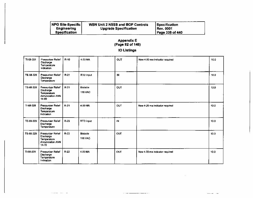
NPG Site-Specific WBN Unit 2 NSSS and BOP Controls SpecificationEngineering Upgrade Specification Rev. 0001Specification Page 338 of 440
Appendix E(Page 92 of 148)
10 Listings
TI-68-331 Pressurizer Relief R-16 4-20 MA OUT New 4-20 ma indicator required 10.0DischargeTemperatureIndication
TE-68-328 Pressurizer Relief R-21 RTD Input IN 10.0DischargeTemperature
TS-68-328 Pressurizer Relief R-21 Bistable OUT 10.0DischargeTemperature 118 VAC
Annunciation ANN14-69
TI-68-328 Pressurizer Relief R-21 4-20 MA OUT New 4-20 ma indicator required 10.0DischargeTemperatureIndication
TE-68-329 Pressurizer Relief R-23 RTD Input IN 10.0DischargeTemperature
TS-68-329 Pressurizer Relief R-23 Bistable OUT 10.0DischargeTemperature 118 VAC
Annunciation ANN14-70
TI-68-329 Pressurizer Relief R-23 4-20 MA OUT New 4-20 ma indicator required 10.0DischargeTemperatureIndication
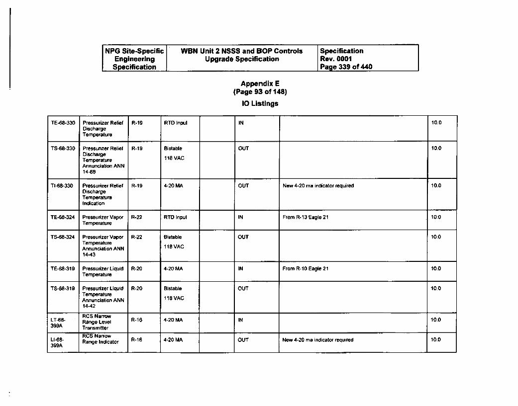
NPG Site-Specific WBN Unit 2 NSSS and BOP Controls SpecificationEngineering Upgrade Specification Rev. 0001
Specification Page 339 of 440
Appendix E(Page 93 of 148)
10 Listings
TE-68-330 Pressurizer Relief R-19 RTD Input IN 10.0DischargeTemperature
TS-68-330 Pressurizer Relief R-1 9 Bislable OUT 10.0DischargeTemperature 118 VACAnnunciation ANN14-68
TI-68-330 Pressurizer Relief R-19 4-20 MA OUT New 4-20 ma indicator required 10.0DischargeTemperatureIndication
TE-68-324 Pressurizer Vapor R-22 RTD Input IN From R-13 Eagle 21 10.0Temperature
TS-08-324 Pressurizer Vapor R-22 Bistable OUT 10.0TemperatureAnnunciation ANN 118 VAC14-43
TE-68-319 Pressurizer Liquid R-20 4-20 MA IN From R-10 Eagle 21 10.0Temperature
TS-68-319 Pressurizer Liquid R-20 Bistable OUT 10.0TemperatureAnnunciation ANN 118 VAC
14-42
RCS NarrowLT-68- Range Level R-16 4-20 MA IN 100399A Transmitter
RCS NarrowLI-68- Range Indicator R-16 4-20 MA OUT New 4-20 ma indicator required 10.0399A
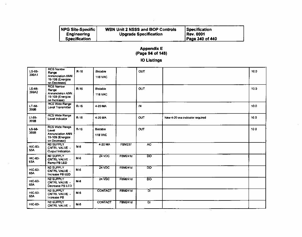
NPG Site-Specific WBN Unit 2 NSSS and 13OP Controls SpecificationEngineering Upgrade Specification Rev. 0001Specification Page 340 of 440
Appendix E(Page 94 of 148)
10 Lis;tings
RCS Narrow"LS-68- Range R-16 Bistable OUT 10.0399A1 Annunciation ANN 118 VAC
19-108 (Energizeon Decrease)
LS-68- RCS Narrow R-16 Bistable OUT 10.0Range399A2 Annunciation ANN 118 VAC
19-109 (Energizeon Increase)RCS Wide Range
399B Level Transmitter R-1 4-20 MA IN 10.0
RCS Wide RangeLI-68- Level Indicator R-16 4-20 MA OUT New 4-20 ma indicator required 10.0399B
ROS Wide RangeLS-68- Level R-16 Bistable OUT 10.03998 Annunciation ANN 118 VAC
19-109 (Energizeon Decrease)N2 SUPPLY 4-20 MA FBM237 AD
HIC-63- CNTRL VALVE - M-665A Output Indication
1N2 SUPPLY 24 VDC FBM24ld DO-HI1-63- CNTRL VALVE - M-665A Ramp PB LED
N2 SUPPLY 24 VDC FBM241d DO-HIC-83- CNTRL VALVE - M-665A Increase PB LED
N2 SUPPLY 24 VDC FBM241d DO-HIC-63- CNTRL VALVE - M-665A Decrease PB LED
N2 SUPPLY CONTACT FBM241d DIHIC-63- CNTRL VALVE - M-665A Increase PB
N2 SUPPLY CONTACT FBM241d DIHIC-63- CNTRL VALVE - M-6
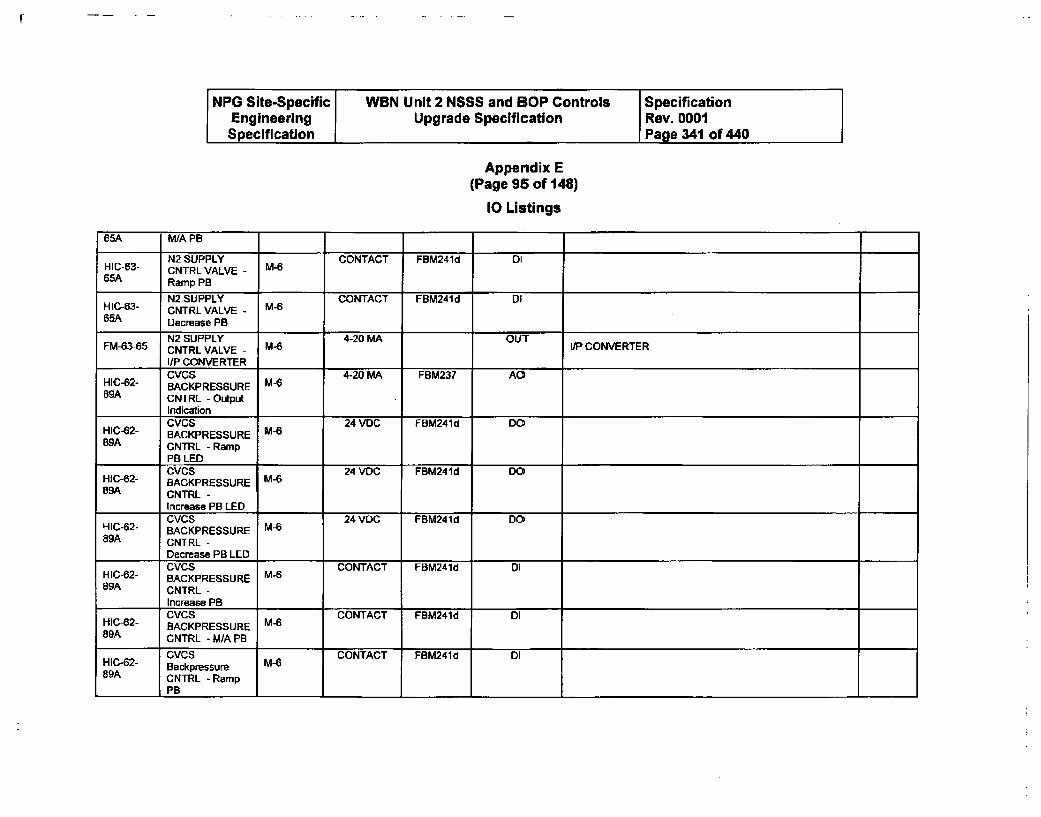
NPG Site-Specific WBN Unit 2 NSSS and BOP Controls SpecificationEngineering Upgrade Specification Rev. 0001Specification Page 341 of 440
Appendix E(Page 95 of 148)
10 Listings
65A WA PB
N2 SUPPLY CONTACT FBM241d DIHIC-63- CNTRL VALVE - M-665A Ramp PB
N2 SUPPLY CONTACT FBM241d DIHIC-63- CNTRL VALVE - M-665A Decrease PB
N2 SUPPLY 4-20 MA OUTFM-63-85 CNTRL VALVE - M-6 IP CONVERTER
I/P CONVERTERCVCS 4-20 MA FBM237 AOHIC-62- BACKPRESSURE M-6
89A CNTRL - OutputIndicationCVCS 24 VDC FBM241d DO
HIC-62- BACKPRESSURE M-689A CNTRL -Ramp
PB LEDCVCS DO24 VDC FBM241d 00
HiC-62- BACKPRESSURE M-289A CNTRL -
Increase PB LEDCVCS 24 VOC FBM241d DO
HIC-62- BACKPRESSURE M-689A CNTRL -
Decrease PB LEDCVCS CONTACT FBM241d DI
HIC-62- BACKPRESSURE M-689A CNTRL -
increase PB
HIC42- CVCS M- CONTACT FBM241d DlH-2- BACKPRESSUREM-89A CNTRL - M/A PB
HC CVCS MG CONTACT FBM241d DIHIC -6 2 - B a ckpres su reM -89A CNTRL - Ramp
PB I
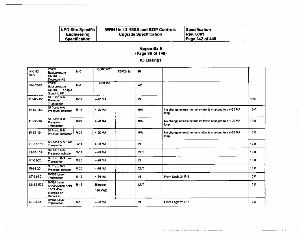
NPG Site-Specific WBN Unit 2 NSSS and BOP Controls SpecificationEngineering Upgrade Specification Rev. 0001Specification Page 342 of 440
Appendix E(Page 96 of 148)
10 Lls;tlngs
HIC-62- Bacs M-6 CONTACT FBM241d IN89A CNTRL -
Decrease PBCVCS 4-20 MA AO
FM-62-89 Backpressure
CNTRL OutputSignal to lIPSI Pump A-A
PT-63-150 Pressure R-17 4-20 MA IN 10.0
TransmitterSI Pump A-A
P1-63-150 Pressure Indicator R-17 4-20 MA N/A No change unless the transmitter is changed to a 4-20 MA 10.0loop
SI Pump B-B
PT-63-19 Pressure R-22 4-20 MA N/A No change unless the transmitter is changed to a 4-20 MA 10.0
Transmitter loop
SI Pump B-BP1-63-19 Pressure Indicator R-22 4-20 MA N;A No change unless the transmitter is changed to a 4-20 MA 10.0
loop
SI Pump A-A FlowFT-63-151 Transmitter R14 4-20 MA IN 10.0
SI Pump A-AF1-63-151 Pressure Indicator R14 4-20 MA OUT 10.0
Si Pump B-B FlowFT-63-20 Transmitter R-20 4-20 MA IN 10.0
SI Pump B-BF1-63-20 Pressure Indicator R20 4-20 MA OUT 10_0
RWST LevelLT-63-50 Transmitter R-16 4-20 MA IN From Eagle 21 R-3 10.0
RWST Level 10,0L8-3-50B Annunciation ANN R-16 Bistable OUT 10.0
15-77 (De- 118 VACenergize onDecrease) .....RWST Level
LT-63-51 Transmitter R-18 4-20 MA IN From Eagle 21 R-7 10.0
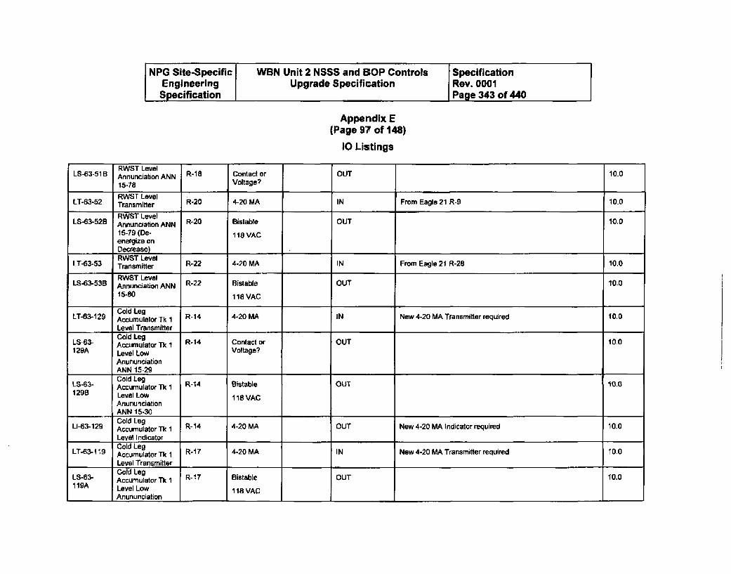
NPG Site-Specific WBN Unit 2 NSSS and BOP Controls SpecificationEngineering Upgrade Specification Rev. 0001Specification Page 343 of 440
Appendix E(Page 97 of 148)
10 Listings
RWST LevelLS-53-51B Annunciation ANN R-18 Contact or OUT 10.0
15-78 Voltage?
RWST LevelLT-63-52 Transmitter R-20 4-20 MA IN From Eagle 21 R-9 10.0
RWST LevelLS-63-52B Annunciation ANN R-20 Bistable OUT 10.0
15-79 (De- 118 VACenergize onDecrease)RWST Level
LT-63-53 TransmtLer l R-22 4-20 MA IN From Eagle 21 R-28 10.0
RWST LevelLS-63-53B Annunciation ANN R22 Bistable OUT 10.0
15-80 118 VAC
Cold Leg
LT-63-129 Accumulator Tk 1 R-14 4-20 MA IN New 4-20 MA Transmitter required 10.0
Level Transmitter
LS-63- Cold Leg R-14 Contact or OUT 10.0L1-93- Accumulator Tk 1 Voltage?129A Level Low Voltage'
AnununciationANN 15-29
L8-63- Cold Leg R-14 Bisable OUT '10.0Accumulator Tk 11298 Level Low 118 VAC
AnununciationANN 15-30Cold Leg
U-83-129 Accumulator Tk 1 R-14 4-20 MA OUT New 4-20 MA Indicator required 10.0
I Level IndicatorLT8-19Cold Leg ....
LT-63-119 Accumulator T 1 R-1 7 4-20 MA IN New 4-20 MA Transmitter required 10.0
Level TransmitterLS-83- Cold Leg11QA Accumulator Tk 1 R-17 Bistable OUT 10.0119A Level Low 118 VAC
Anununciation
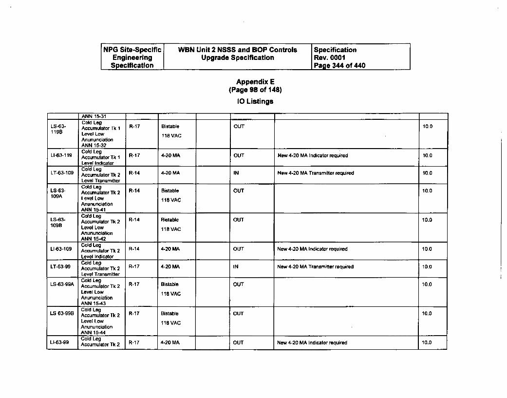
NPG Site-Specific WBN Unit 2 NSSS and BOP Controls SpecificationEngineering Upgrade Specification Rev. 0001Specification Page 344 of 440
Appendix E(Page 98 of 148)
10 Listings
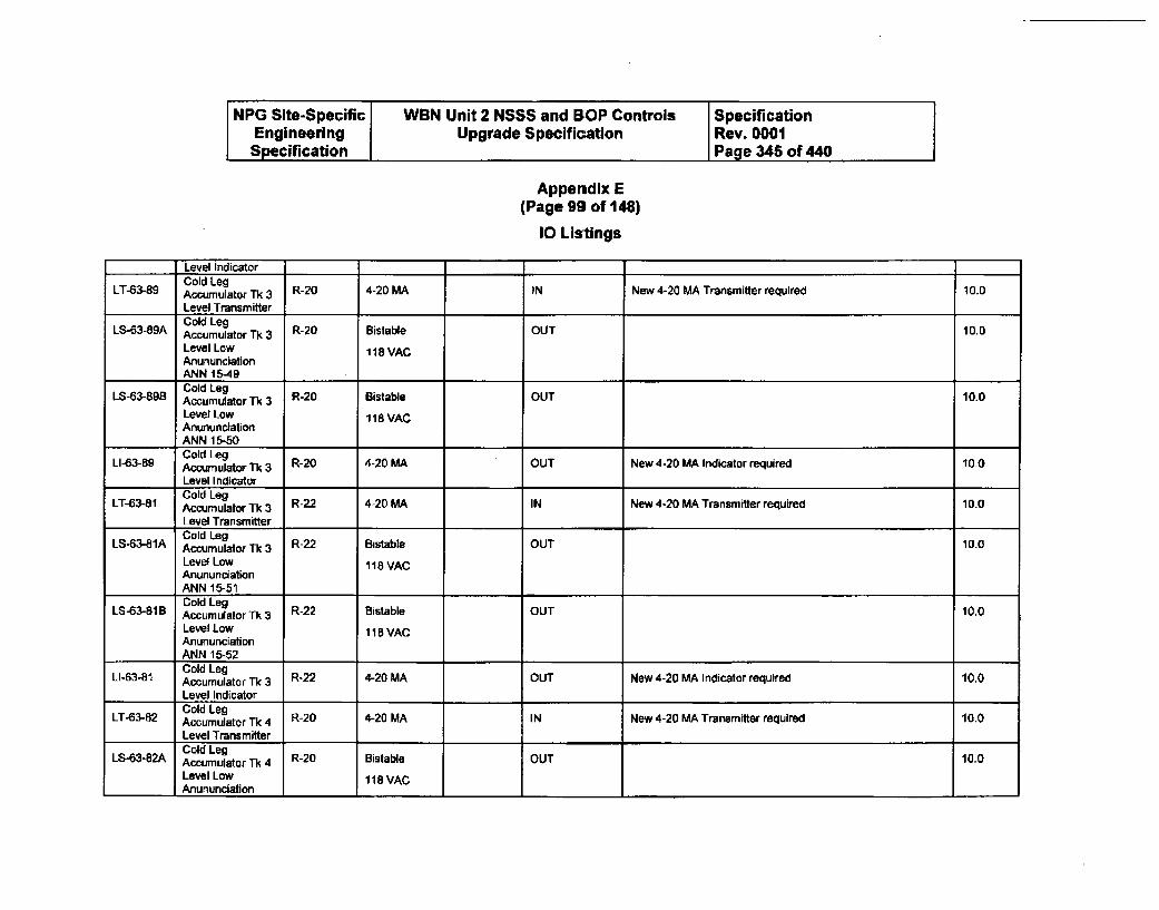
NPG Site-Specific WBN Unit 2 NSSS and BOP Controls SpecificationEngineering Upgrade Specification Rev. 0001Specification Page 345 of 440
Appendix E(Page 99 of 148)
10 Listings
Level IndicatorCold Leg
LT-63-89 Accumulator Tk 3 R-20 4-20 MA IN New 4-20 MA Transmitter required 10.0Level TransmitterCold Leg
LS-83-89A Accumulator Tk 3 R-20 Bistable OUT 10.0Level Low 118VACAnununciationANN 1t-49Cold Leg
LS-63-89B Accumulator Tk 3 R-20 Bistable OUT 10.0Level Low 118 VACAnununciationANN 15-50"Cold Leg
LI-63-89 Accumulator Tk 3 R-20 4-20 MA OUT New 4-20 MA Indicator required 10.0Level IndicatorCold Leg
LT-63-81 Accumulator Th 3 R-22 4-20 MA IN New 4-20 MA Transmitter required 10.0Level Transmitter_Cold Leg
LS-63-81A AccumulatordTk 3 R-22 Bistable OUT 10.0Level Low 118 VACAnununciationANN 15-51Cold Leg
LS-6341B Accumulator Tk 3 R-22 Bistable OUT 10.0Level Low 118 VACAnununciationANN 15-52Cold Leg
LI-3B1 Accumulator Tk 3 R-22 4-20 MA OUT New 4-20 MA Indicator required 10.0Level IndicatorCold Leg
LT-63-82 Accumulator Tk 4 R-20 4-20 MA IN New 4-20 MA Transmitter required 10.0Level TransmitterCold Leg
LS-63-82A Accumulator Tk 4 R-20 Bistable OUT 10.0Level Low 118VAC
_Anununciation I I I
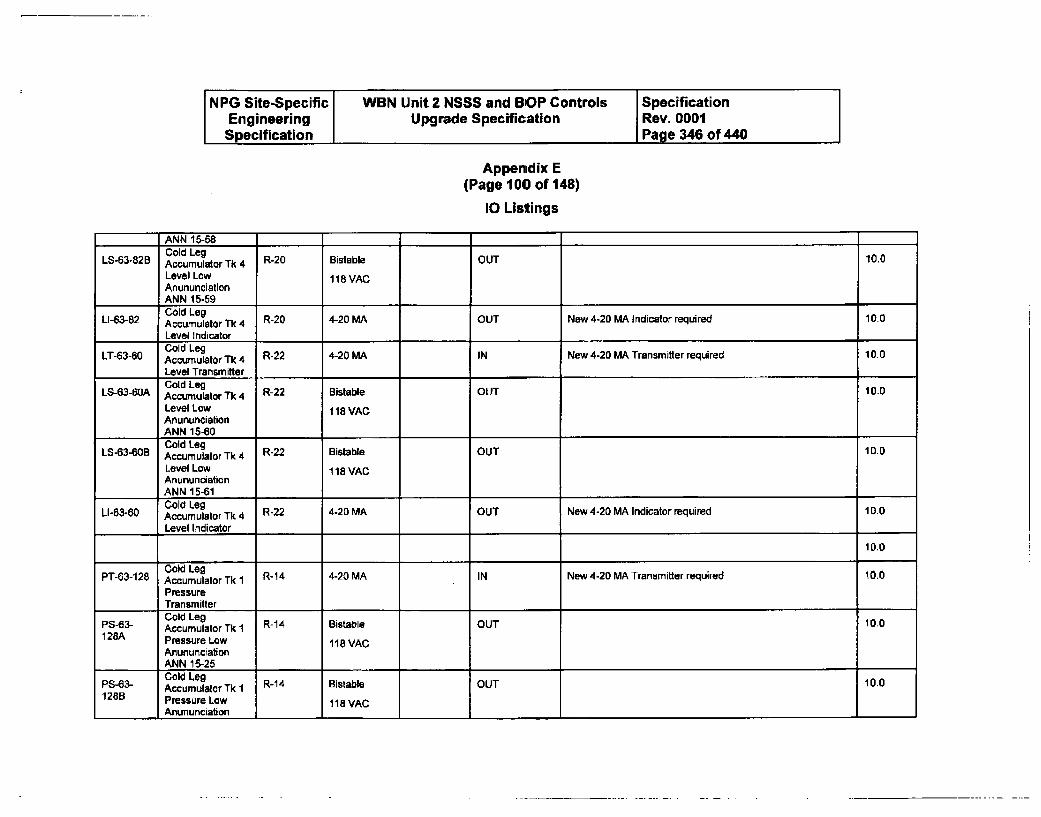
NPG Site-Specific WBN Unit 2 NSSS and BOP Controls SpecificationEngineering Upgrade Specification Rev. 0001Specification Page 346 of 440 I
Appenidix E(Page 100 of 148)
10 Listings
9 r ¶ I 7ANN 15-58Cold Leg
LS-63-82B Accumulator Tk 4 R-20 Bistable OUT 10.0
Level Low 11B VACAnununciationANN 15-59Cold Leg
LI-63-82 Accumulator TL 4 R-20 4-20 MA OUT New 4-20 MA Indicator required 10.0
Level IndicatorCold Leg
LT-63-60 Accumulator Tk 4 R-22 4-20 MA IN New 4-20 MA Transmitter required 10.0
Level TransmitterCold Leg
LS-63-40A Accumulator Tk 4 R-22 Bistable OUT 10.0Level Low 118 VACAnununciationANN 15-60Cold Leg R-22 Bistable OUT 10.0
LS-63-60B Accumulator Tk 4Level Low 118 VACAnununciationANN 15-61Cold Leg
LI-63-60 Accumulator Tk 4 R-22 4-20 MA OUT New 4-20 MA Indicator required 10.0
Level Indicator
10.0
Cold LegPT-63-128 Accumulator Tk I R-14 4-20 MA IN New 4-20 MA Transmitter required 10.0
PressureTransmitterCold LegAccumulator Tk I R14 Bistable OUT 10.0
128A Pressure Low 118 VAC
AnununciationANN 15-25Cold Leg
P8-63- Accumulator Tk i R14 Bistable OUT 100128B Pressure Low 118 VAC
Anununciation 1 -1 1 1 1 1
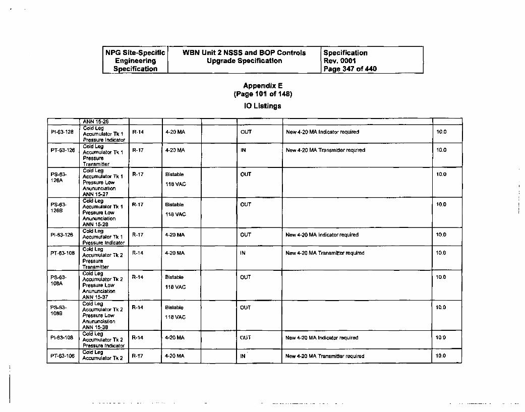
NPG Site-Specific WBN Unit 2 NSSS and B'OP Controls SpecificationEngineering Upgrade Specification Rev. 0001Specification Page 347 of 440
Appendix E(Page 101 of 148)
10 Listings
ANN 15-26Cold Leg
PI-63-128 Accumulator Tk L R-14 4-20 MA OUT New 4-20 MA Indicator required 10.0
Pressure Indicator ....Cold Leg
PT-3-126 Accumulator Tk R-17 4-20 MA IN New 4-20 MA Transmitter required 10.0
PressureTransmitter
PS63 Accumulator k 1 R-17 Bistable OUT 10.0126A Pressure Low 118VAC
AnununciationANN 15-27Cold LegPS-63- Accumulator Tk 1 R-7 Bistable OUT 10.0
126B Pressure Low 118 VAC
AnununciationANN 15-28
P-316 Cold LegP-3-126 Accumulator k R-17 4-20 MA OUT New 4-20 MA Indicator required 10.0
Pressure IndicatorPT-83-108 Cold Leg
Accumulator ok 2 R-14 4-20 MA IN New 4-20 MA Transmitter required 10.0
PressureTransmitterCold Leg
P"3- Accumulator Tk 2 R-14 Bistable OUT 10.0108A Pressure Low 118 VAC
AnununclationANN 15-37Cold LegPS-83- Accumulator Tk 2 R-4 Bistable OUT 10.0
108B Pressure Low 118 VAC
AnununciatlonANN 15-38Cold Leg
P-63108 Accumulator Tk 2 R-14 4-20 MA OUT New 4-20 MA Indicator required 100Pressure IndicatorCold Leg
PT-63-106 Accumulator Tk 2 R-17 4-20 MA IN New 4-20 MA Transmitter required 10.0
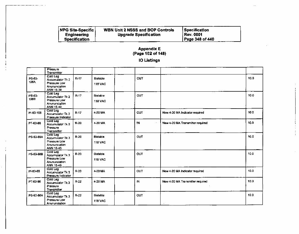
NPG Site-Specific WBN Unit 2 NSSS and BOP Controls SpecificationEngineering Upgrade Specification Rev. 0001Specification Page 348 of 440
Appenidix E(Page 102 of 148)
10 Listings
PressureTransmitterCold Leg
PS-63- Accumulator Tk 2 R17 Bistable OUT 10.0106A Pressure Low 118 VAC
AnununciationANN 15-39
PS0- Cold LegPS-63- AccumulatorTk 2 R-17 Bistable OUT 10.0106B Pressure Low 118 VAC
AnununciationANN 15-40Cold Leg
pi-63-106 Accumulator Tk 2 R-1 7 4-20 MA OUT New 4-20 MA Indicator required 10.0Pressure IndicatorCold Leg
PT-63-88 Accumulator Tk 3 R-20 4-20 MA IN New 4-20 MA Transmitter required 10.0PressureTransmitterCold Leg
PS-63-88A Accumulator Tk 3 R-20 Bistable OUT 10.0Pressure Low 118 VACAnununciationANN 15-45Cold Leg
P-543-8B Accumulator Tk 3 R20 Bistabte OUT 10.0Pressure Low 118 VACAnununciationANN 15-46Cold Leg
PI-63-88 Accumulator Tk 3 R-20 4-20 MA OUT New 4-20 MA Indicator required 10.0Pressure IndicatorCold Leg
PT-63-86 Accumulator TL 3 R-22 4-20 MA IN New 4-20 MA Transmitter required 10.0
PressureTransmitterCold Leg
PS-63-86A Accumulator Tk 3 R-22 Bistable OUT 10.0Pressure Low 118 VACAnununciation
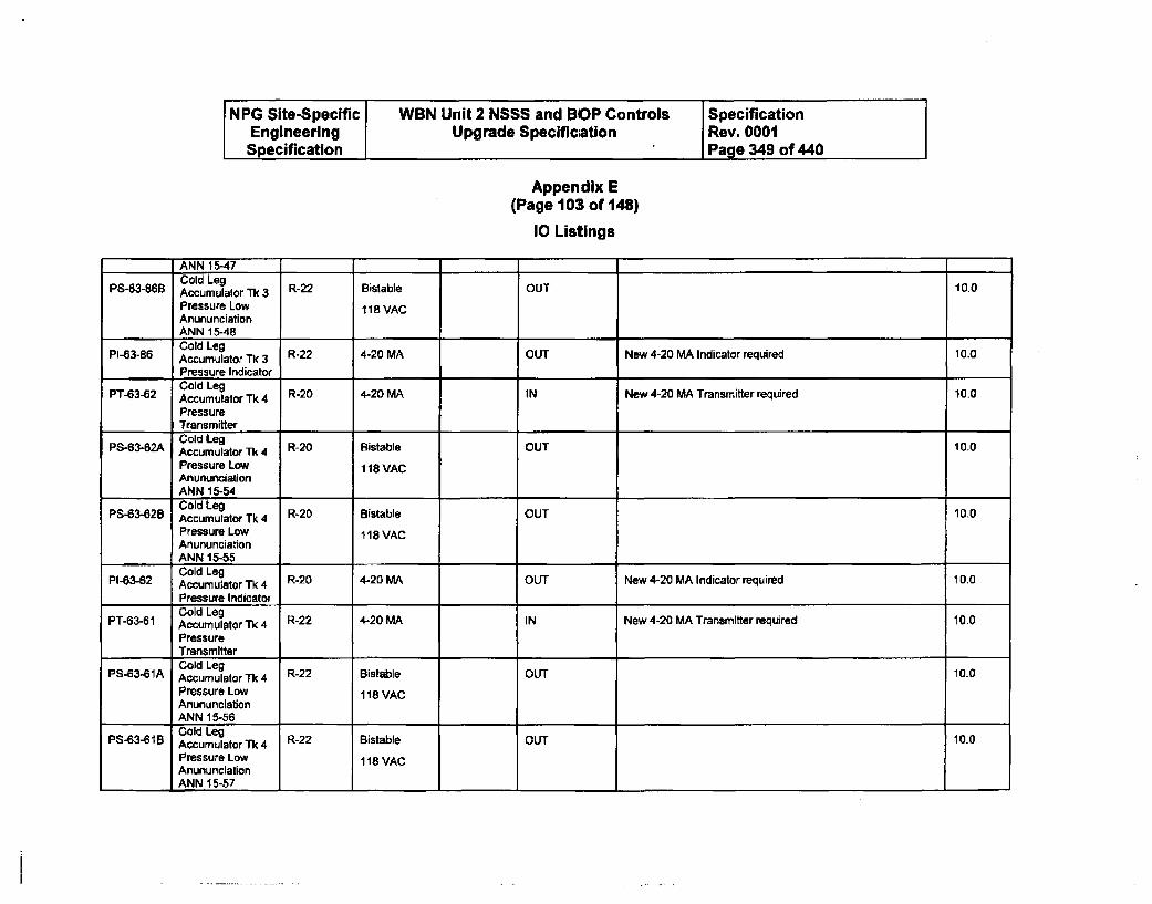
NPG Site-Specific WBN Unit 2 NSSS and BOP Controls SpecificationEngineering Upgrade Specific~ation Rev. 0001Specification Page 349 of 440
Appendix E(Page 103 of 148)
10 Listings
ANN 15-47Cold Leg
PS-63-86B Accumulator Tk 3 R-22 Bistable OUT 10.0Pressure Low 118 VACAnununciationANN 15-48Cold Leg
PI-63-86 Accumulator Tk 3 R-22 4-20 MA OUT New 4-20 MA Indicator required 10.0
Pressure IndicatorCold Leg
PT-63-62 Accumulator Tk 4 R-20 4-20 MA IN New 4-20 MA Transmitter required 10.0
PressureTransmitterCold Leg
PS-63-62A Accumulator Tk 4 R-20 Bistable OUT 10.0
Pressure Low 118 VACAnununciationANN 15-54Cold Leg
PS-63-428 Accumulator Tk 4 R-20 Bistable OUT 10.0Pressure Low 118 VACAnununciationANN 15-55Cold Leg
PI-63-62 Accumulator Tk 4 R-20 4-20 MA OUT New 4-20 MA Indicator required 10.0Pressure Indicator ,Cold Leg ,,
PT-63-61 Accumulator 4 R-22 4-20 MA IN New 4-20 MA Transmitter required 10.0
PressureTransmitterCold Leg
PS-63-61A Accumulator Tk 4 R-22 Bistable OUT 10.0Pressure Low 118 VACAnununciationANN 15-56Cold Leg 10.0
PS-43-618 AccumulatorTk4 R-22 Bistable OUTPressure Low 118 VACAnununciationANN 15-57
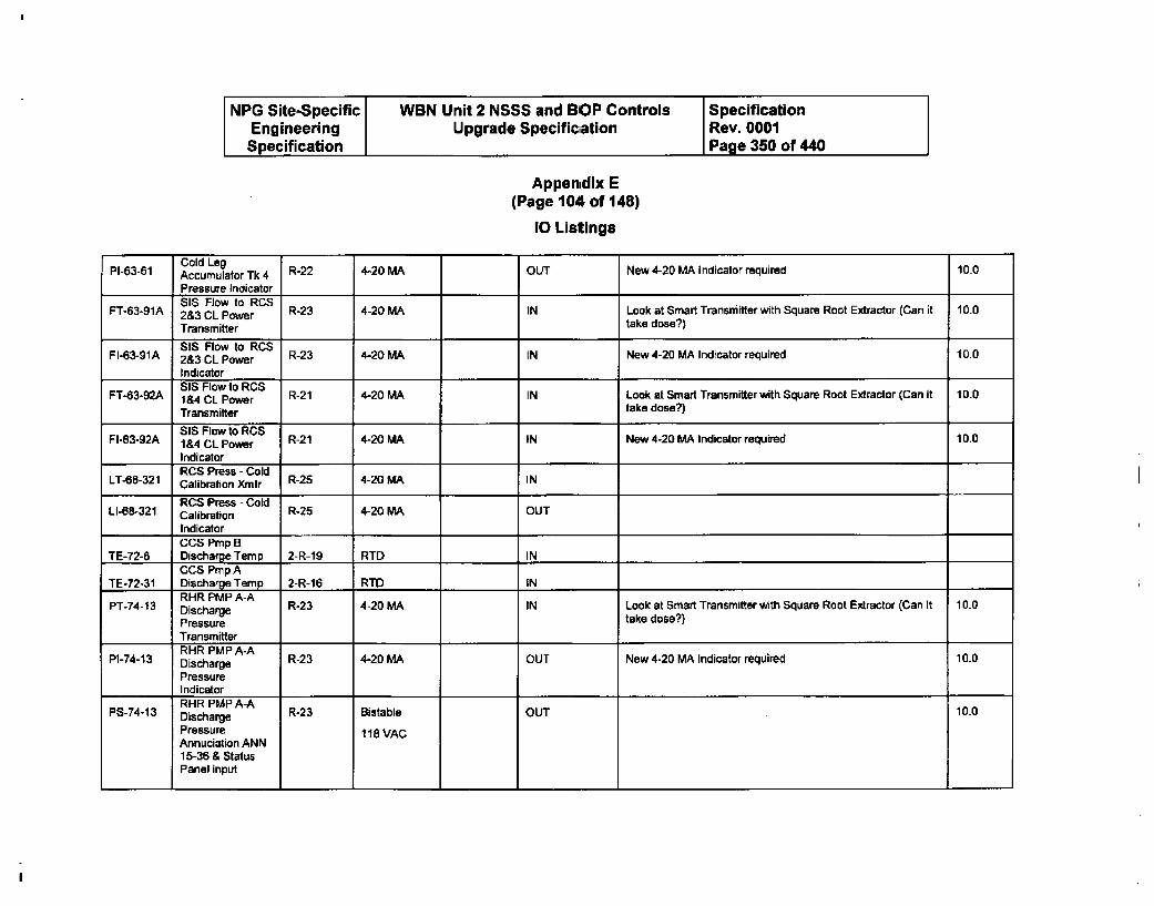
NPG Site-Specific WBN Unit 2 NSSS and BOP Controls SpecificationEngineering Upgrade Specificiation Rev. 0001Specification Page 350 of 440
Appen~dix E(Page 104 of 148)
10 Listings
Cold LegPI-63-61 Accumulator Tk 4 R-22 4-20 MA OUT New 4-20 MA Indicator required 10.0
Pressure indicator'$18 Flow to RCS
FT-63-91A 2&3 CL Power R-23 4-20 MA IN Look at Smart Transmitter with Square Root Extractor (Can it 10.0
Transmitter take dose?)818 Rllow to RCS
FI-63-91A 2&3 CL Power R-23 4-20 MA IN New 4-20 MA Indicator required 10.0
Indicator I818 Flowlto RCS
FT-63-92A 1 &4 CL Power R-21 4-20 MA IN Look at Smart Transmitter with Square Root Extractor (Can it 10.0
Transmitter take dose?)818 Flow to R'CS"'
FI-63-92A 1&4 CL Power R-21 4-20 MA IN New 4-20 MA Indicator required 10.0
IndicatorRCS Press - Cold
LT-68-321 Calibration Xmtr R-25 4-20 MA INRCS Press - Cold
LI-68-321 Calibration R-25 4-20 MA OUT
IndicatorCCS Pmp B
TE-72-6 Discharge Temp 2-R-19 RTD INCCS Prop A
TE-72-31 Discharge Temp 2-R-16 RTID IN ..RHR PUP A-A
PT-74-13 Discharge R-23 4-20 MA IN Look at Smart Transmitter with Square Root Extractor (Can it 10.0
Pressure take dose?)Transmitter
PI-74-13 sPMhPA-A R-23 4-20 MA OUT New 4-20 MA Indicator required 10.0P17-3 Discharge 1.
PressureIndicatorRHR PMP A-A 10.0
P6-74-13 Discharge R23 Bistable OUTPressure 118 VACAnnuciation ANN15-36 & StatusPanel input
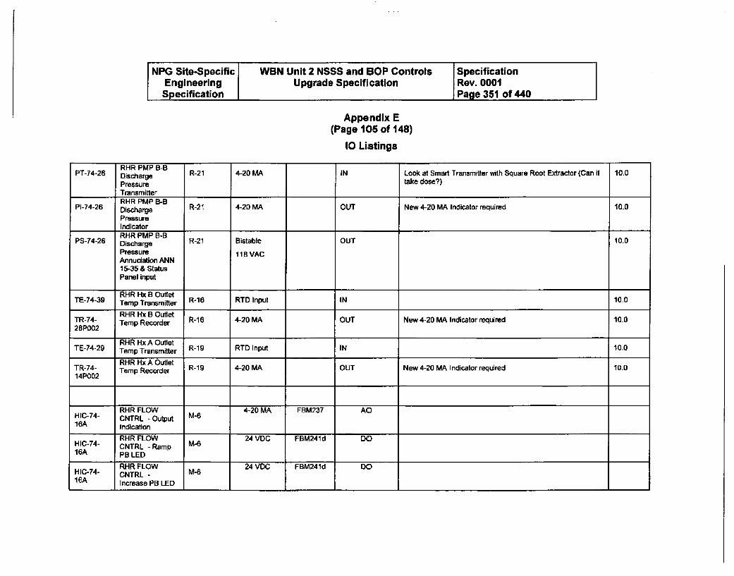
NPG Site-Specific WBN Unit 2 NSSS and BOP Controls I SpecificationEngineering Upgrade Specifi cation Rev. 0001Specification Page 351 of 440
Appendix E(Page 106 of 148)
10 Listings
PT-74-26 RHRarge R-21 4-20 MA IN Look at Smart Transmitter with Square Root Extractor (Can it 10.0
Pressure take dose?)TransmitterRMR PMP B-B
PI-74-26 Discharge R-21 4-20 MA OUT New 4-20 MA Indicator required 10.0
PressureIndicatorRHR PMP B-B
PS-74-26 Discharge R-21 Bistable OUT 10.0
Pressure 118 VACAnnuciation ANN16-35 & StatusPanel input
RHR Hx 8 OutletTE-74-39 Temp Transmitter R-1 RTD Input IN 10.0
RHR Hx B OutletTR-74- Temp Recorder R-16 4-20 MA OUT New 4-20 MA Indicator required 10.026P002
RHR Hx A OutletTE-74-29 Temp Transmitter R-19 RTD Input IN 10.0
RHR Hx A OutletTR-74- Temp Recorder R-19 4-20 MA OUT New 4-20 MA Indicator required 10.014P002
RHR FLOW 4-20 MA FBM237 AOHIC-74- CNTRL - Output M-616A Indication
RHR FLOW 24 VDC FBM241d DOHIC-74- CNTRL - Ramp 2V,16A PB LED
RHR FLOW FBM241d DOHIC-74- CNTRL - M-6IBA Increase PB LED
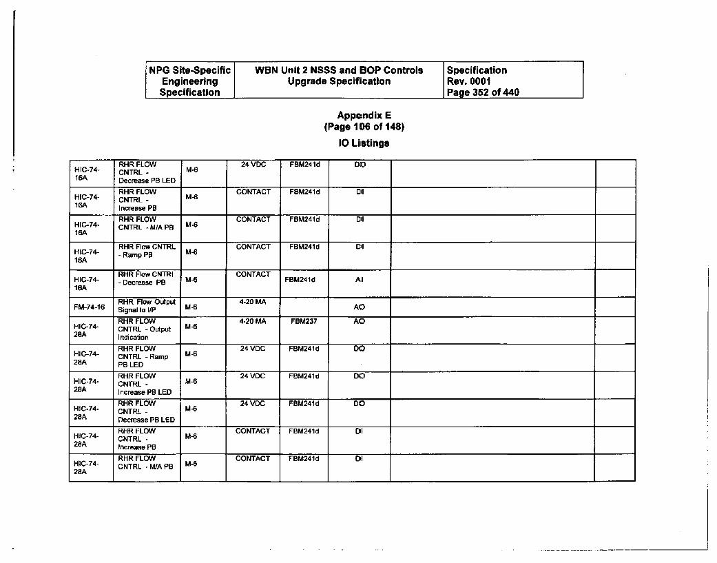
NPG Site-Specific WBN Unit 2 NSSS and BOP Controls SpecificationEngineering Upgrade Specification Rev. 0001Specification Page 352 of 440
Appendix E(Page 106 of 148)
10 Listings
RHR FLOW 24 VDC FBM24Id DOHIC-74- CNTRL - M-616A Decrease PB LED
RHR FLOW CONTACT FBM241 d OiHIC-74- CNTRL - M-616A Increase PB
RHR FLOW CONTACT FBM241d oiHIC-74- CNTRL - MIA PB M-616A
RHR Flow CNTRL MCONTACT FBM241d DI1I6-74- - Ramp PB M-616A
RHR Flow CNTRL CONTACTHIC0-74- - Decrease PB M- FRM24Id Al16A
RHR Flow Output 4-20 MAFM-74-16 Signal to liP M-6 AO
RHR FLOW 4-20 MA FBM237 AOHIC-74- CNTRL - Output M-628A Indication
RHR FLOW 24 VDC FBM241 d DOHIC-74- CNTRL - Ramp M-628A PB LED
RHR FLOW 24 VDC FBM241 d DOHIC-74- CNTRL - M-628A Increase PB LED
HIC-74- RHR FLOW M-6 24 VDC FBM241d DOCNTRL -
28A Decrease PB LED
RHR FLOW CONTACT FBM241d DiIHIC-74- CNTRL - M-S28A Increase PB
RHR FLOW CONTACT FBM241d O 1HIC-74- CNTRL - MA PB M-628A
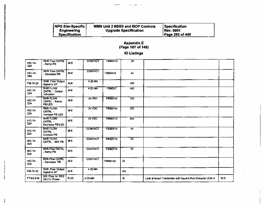
NPG Site-Specific WBN Unit 2 NSSS and BOP Controls SpecificationEngineering Upgrade Specifiication Rev. 0001Specification Page 353 of 440
Appendix E(Page 107 of 148)
10 Listings
RHR Flow CNTRL CONTACT FBM241d DilH2C-4 - Ramp PB M628A
HIC-74- RHR Flow CNTRL 1 CONTACTA28A - Decrease PB MS 6 CONTAC28A
RHR Flow Output 4-20 MASignal to I/P
RHR FLOW 4-20 MA FBM237 AOHIC-74- CNTRL - Output M-632A Indication
RHR FLOW 24 VDC FBM241d DOH1C-44 CNTRL - Ramp M2432A PB LED
RHR FLOW 24 VDC FBM241d DOHIC-74- CNTRL - 2DM32A Increase PB LED
HIC-14- RHR FLOW 24 VDC FBM241d DOCNTRL - M-6
32A Decrease PB LED
RHR FLOW M6CONTACT FBM24ld DIH IC-74- CNTRL - U-C32A increase PB
RHR FLOW CONTACT FBM241d DlHIC-74- CNTRL - M/A PB M-632A
HIC-74- RHR Flow CNTRL M-6 CONTACT FBM241d DI
32A - Ramp PB
RHR Flow CNTRL CONTACTHIC-74- - Decrease PB MCT FBM241d Dl32A
RHR Flow Output 4-20 MAFM-74-32 Signal to I/P M- AI
SIS Flow to RCSFT-63-91B 2&3 CL Power R-23 4-20 MA IN Look at Smart Transmitter with Square Root Extractor (Can it 100
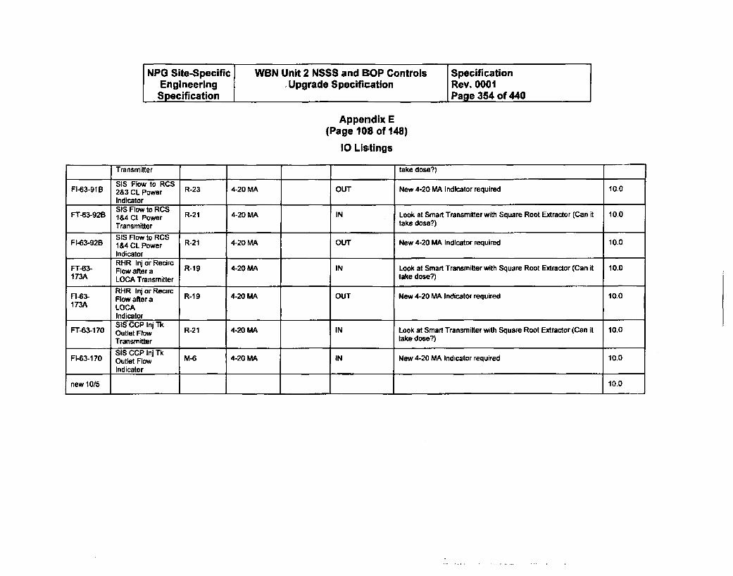
NPG Site-Specific WBN Unit 2 NSSS and BOP Controls SpecificationEngineering Upgrade Specification Rev. 0001Specification Page 354 of 440
Appendix E(Page 108 of 148)
10 Listings
Transmitter take dose?)
SIS Flow to RCS , ,.
FI-63-91 B 2&3 CL Power R-23 4-20 MA OUT New 4-20 MA Indicator required 10.0IndicatorSIS Flow to RCS
FT63-92B &4 CL Power R-21 4-20 MA IN Look at Smart Transmitter with Square Root Extractor (Can it 10.0
Transmitter take dose?)
51S flow to RCSFI-63-926 i&4 CL Power R-21 4-20 MA OUT New 4-20 MA Indicator required 10.0
IndicatorRHR Inj or Recirc
FT-63- Flow after a R-19 4-20 MA IN Look at Smart Transmitter with Square Root Extractor (Can it 10.0173A LOCA Transmitter take dose?)
RHR Inj or RecirtFI-63- FlOw after a R-1 9 4-20 MA OUT New 4-20 MA Indicator required 10.0173A LOCA
IndicatorSIS CCP Inj Trk
FT-63-170 Outlet Flow 1R-21 4-20 MA IN Look at Smart Transmitter with Square Root Extractor (Can it 10.0
Transmitter take dose?)
SIS CCP Inj TkFI-63-170 Outlet Flow M-6 4-20 MA IN New 4-20 MA Indicator required 10.0
Indicator
new 10/5 10.0
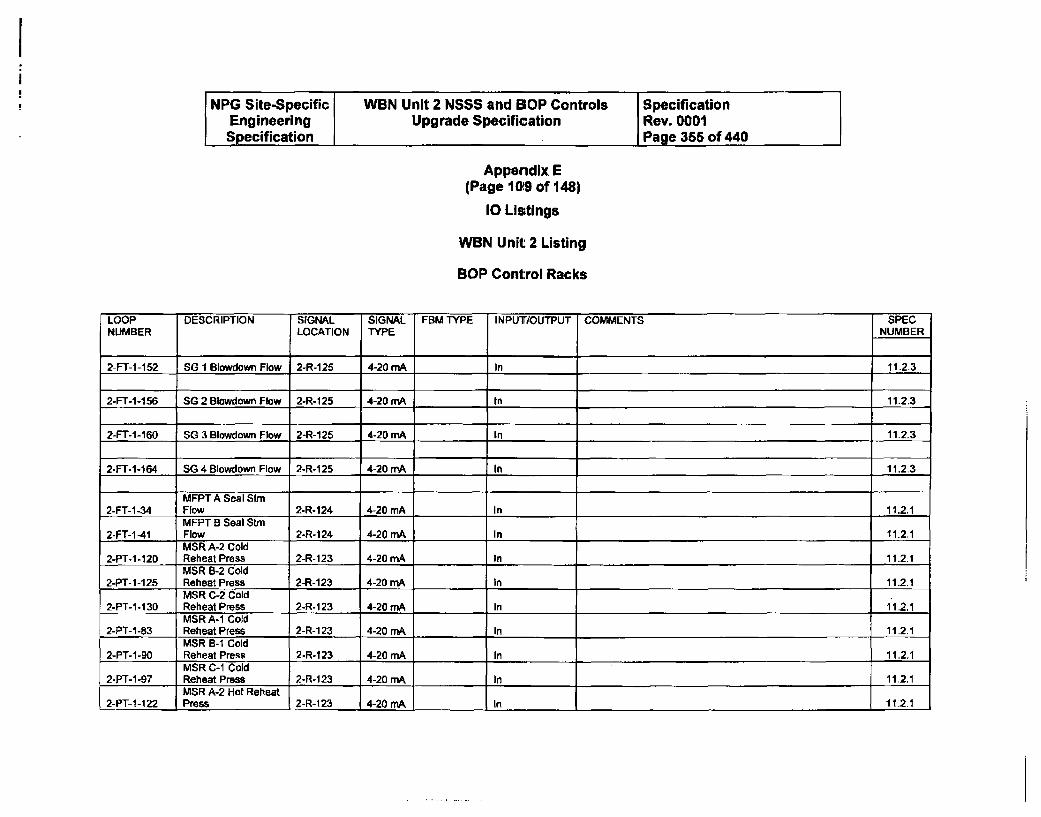
NPG Site-Specific WBN Unit 2 NSSS and BOP Controls SpecificationEngineering Upgrade Specification Rev. 0001Specification I Page 365 of 440
Appendix E(Page 109 of 148)
10 Listings
WBN Unit 2 Listing
BOP Control Racks
LOOP DESCRIPTION SIGNAL SIGNAL FBM TYPE INPUT/OUTPUT COMMENTS SPECNUMBER LOCATION TYPE NUMBER
2-Fr-1-152 SG 1 Blowdown Flow 2-R-125 4-20 mA In 11.2-3
2-FT-1-156 SG 2 Blowdown Flow 2-R-125 4-20 mA In 11.2.3
2-FT-1-160 SG 3 Blowdown Flow 2-R-125 4-20 mA In 11-2.3
2-FT-1-164 SG 4 Blowdown Flow 2-R-125 4-20 mA I In 11.2.3
MFPT A Seal Stm2-FT-1-34 Flow 2-R-124 4-20 mA In 11.2.1
MFPT B Seal Stm2-FT-1-41 Flow 2-R-124 4-20 mA In 11.2.1
MSR A-2 Cold2-PT-1-120 Reheat Press 2-R-123 4-20 mA In 11.2.1
MSR B-2 Cold2-PT-1-125 Reheat Press 2-R-123 4-20 mA In 11.2.1
MSR C-2 Cold2-PT-i-130 Reheat Press 2-R-123 4-20 mA In 11.2.1
MSR A-1 Cold2-PT-I-83 Reheat Press 2-R-1 23 4-20 mA In 11.2.1
MSR B-I Cold2-PT-I-90 Reheat Press 2-R-123 4-20 mA In 11.2.1
MSR C-1 Cold2-PT-1 -97 Reheat Press 2-R-123 4-20 mA In 11.2.1
MSR A-2 Hot Reheat2-PT-1-122 Press 2-R-123 4-20 mA In 112.1
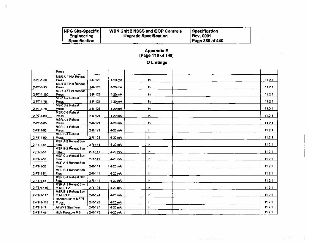
NPG Site-Specific WBN Unit 2 NSSS and BOP Controls SpecificationEngineering Upgrade Specification Rev. 0001
Specification , Page 356 of 440
Appendix E(Page 110 of 148)
10 Listings
PressMSR A-I Hot Reheat
2-PT-1-86 Press 2-R-123 4-20 mA In 11.2.1MSR B-I Hot Reheat
2-PT-1-93 Press 2-R-123 4-20 mA In 11.2.1MSR C-I Hot Reheat
2-PT-1-100 Press 2-R-123 4-20 mA In 11.2.1MSR A-2 Reheat
2-PT-1-76 Press 2-R-121 4-20 mA In 11,2.1MSR B-2 Reheat
2-PT-1-78 Press 2-R-121 4-20 mA In 11.2.1MSR C-2 Reheat
2-PT-1-80 Press 2-R-121 4-20 mA In 11.2.1MSR A-1 Reheat
2-PT-1-85 Press 2-R-121 4-20 mA In 11.2.1MSR B-1 Reheat
2-PT-1-92 Press 2-R-121 4-20 mA In 11.2.1MSR C-1 Reheat
2-PT-1-SQ Press 2-R-121 4-20 mA In 11.2.1MSR A-2 Reheat Stm
2-FT-1-56 Flow 2-R-141 4-20 mA In 11.2.1MSR B-2 Reheat Stm
2-FT-1-57 Flow 2-R-141 4-20 mA In 11.2.1MSR C-2 Reheat Stm
2-FT-1-58 Flow 2-R-141 4-20 mA In 11.2.1MSR A-1 Reheat Stm
2-FT-1-53 Flow 2-R-141 4-20 mA In 11.2.1MSR B-I Reheat Stm
2-FT-1-54 Flow 2-R-141 4-20 mA In 11.2.1MSR C-I Reheat Stm
2-FT-1-55 Flow 2-R-141 4-20 mA In 11.2.1MSR A-I Reheat Stmr
2-FT-1-1 16 to MFPT A 2-R-124 4-20 mA In 11.2.1MSR B-I Reheat Stm
2-FT-1-117 to MFPT B 2-R-124 4-20 mA In 11.2.1Reheat Stir to MFPT
2-PT-1-118 Press 2-R-123 4-20 mA In 11.2.12-FT-1-17 AFWPT Stm Flow 2-R-137 4-20 mA In 11.2.1
2-PT-1-48 High Pressure US 2-R-123 4-20 mA In 11.21
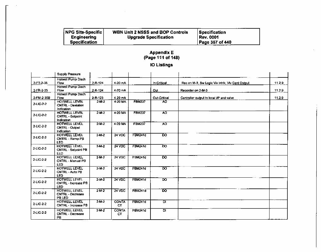
NPG Site-Specific WBN Unit 2 NSSS and BOP Controls SpecificationEngineering Upgrade Specification Rev. 0001Specification Page 357 of 440
Appendix E(Page 1III of 148)
10 Listings
Supply Pressure
Hotwell Pump DIsch2-FT-2-35 Flow 2-R-124 4-20 mA In-Crltical Rec on M-3, Sw Logic VIv Intdk, VMv Cont Output 11.2.9
Hotwell Pump Disch2-FR-2-35 Flow 2-R-124 4-20 mA Out Recorder on 2-M-3 11.2.9
Hotweli Pump Disch2-FM-2-35B Flow 2-R-123 4-20 mA Out-Critical Controller output to local I/P and valve 11.2.9
HOTWELL LEVEL 2-M-2 4-20 MA FBM237 AO2-LlC-2-2 CNTRL - Deviation
IndicationHOTWELL LEVEL 2-M-2 4-20 MA FBM237 AO
2-UC-2-2 CNTRL - SetpointIndicationHOTWELL LEVEL 2-M-2 4-20 MA FBM237 AO
2-LIC-2-2 CNTRL - OutputIndicationHOTWELL LEVEL 2-M-2 24 VDC FBM241d DO
2-LIC-2-2 CNTRL - Ramp PBLEDHOTWELL LEVEL 2-M-2 24 VDC FBM241d DO
2-LIC-2-2 CNTRL - Setpoint PBLEDHOTWELL LEVEL 2-M-2 24 VDC FBM241d DO
2-LIC-2-2 CNTRL - Manual PBLEDHOTWELL LEVEL 2-M-2 24 VDC FBM241d DO
2-LIC-2-2 CNTRL - Auto PBLEDHOTWELL LEVEL 2-M-2 24 VDC FBM241d DO
2-LIC-2-2 CNTRL - Increase PBLEDHOTWELL LEVEL 2-M-2 24 VDC FBM241d DO
2-LIC-2-2 CNTRL - DecreasePB LEDHOTWELL LEVEL 2-M-2 CONTA FBM241d DI
2-LIC-2-2 CNTRL- Increase PB CT
HOTWELL LEVEL 2-M-2 CONTA FBM241d DI2-LIC-2-2 CNTRL - Decrease CT
PB
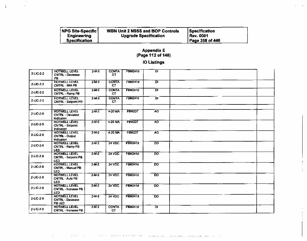
NPG Site-Specific WBN Unit 2 NSSS and BOP Controls SpecificationEngineering Upgrade Specification Rev. 0001Specification I Page 358 of 440
Appemdix E(Page 11:2 of 148)
10 Listings
2-LIC-2-2HOTWELL LEVELCNTRL - DecreasePB
2-M-2 CONTACT
FBM24 Id DI
HOTWELL LEVEL 2-M-2 CONTA FBM241d DI2-LIC-2-2 CNTRL - M/A PB CT
HOTWELL LEVEL 2-M-2 CONTA FBM241d D02-LIC-2-2 CNTRL - Ramp PB CT
HOTWELL LEVEL 2-M-2 CONTA FBM241d DI2-LIC-2-2 CNTRL - Setpoint PB CT
HOTWELL LEVEL 2-M-2 4-20 MA FBM237 AD2-LIC-2-9 CNTRL - Deviation
IndicationHOTWELL LEVEL 2-M-2 4-20 MA FBM237 AO
2-LIC-2-9 CNTRL - SetpointIndicationHOTWELL LEVEL 2-M-2 4-20 MA FBM237 AO
2-LICo2-9 CNTRL - OutputIndicationHOTWELL LEVEL 2-M-2 24 VDC FBM241d DO
2-LIC-2-9 CNTRL - Ramp PBLEDHOTWELL LEVEL 2-M-2 24 VDC FBM241d DO
2-LIC-2-9 CNTRL - Setpoint PBLEDHOTWELL LEVEL 2-M-2 24 VDC FBM241d DO
2-LIC-2-9 CNTRL - Manual PBLEDHOTWELL LEVEL 2-M-2 24 VDC FBM241d DO
2-LIC-2-9 CNTRL - Auto PBLEDHOTWELL LEVEL 2-M-2 24 VDC FBM241d DO
2-LIC-2-9 CNTRL - Increase PBLEDHOIWELL LEVEL 2-M-2 24 VDC FBM241d DO
2-LIC-2-9 CNTRL - Decrease
PB LEDHOTWELL LEVEL 2-M-2 CONTA FBM241d DI
2-LIC-2-9 CNTRL - Increase PB CT
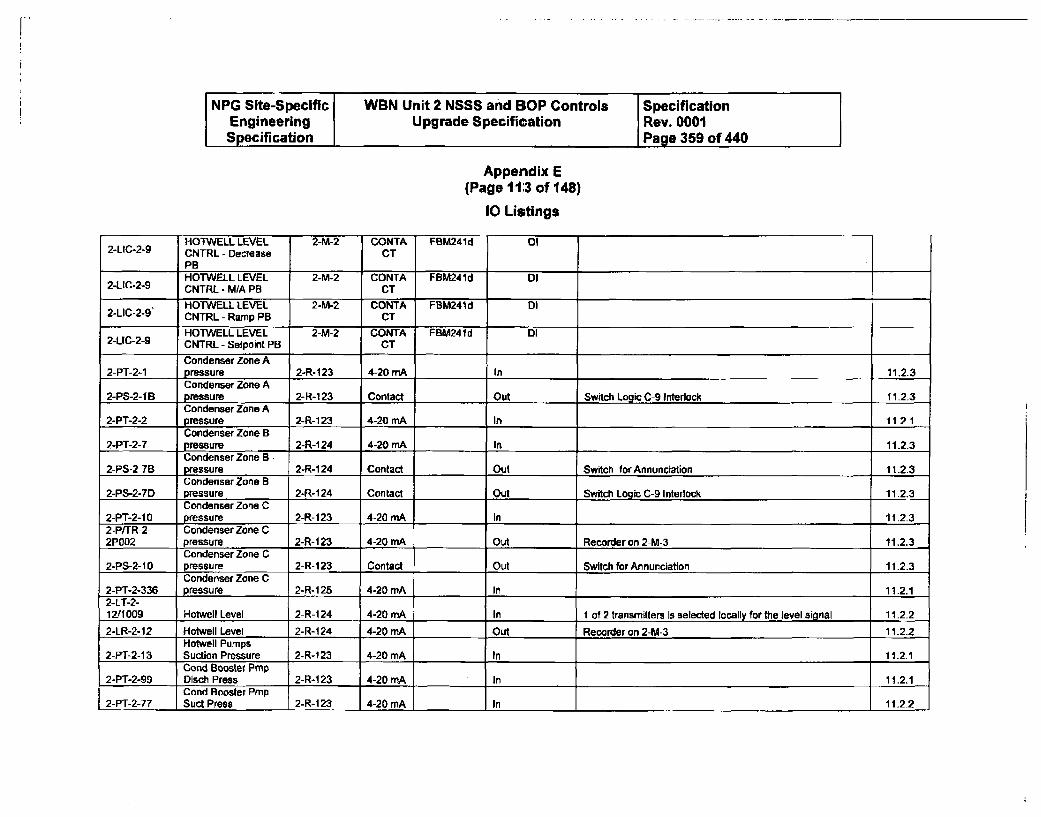
NPG Site-Specific WBN Unit 2 NSSS and BOP Controls SpecificationEngineering Upgrade Specification Rev. 0001Specification Page 359 of 440
Appendix E(Page 11:3 of 148)
10 Listings
-------- ~r-1-r~-----, - - .~ - ¶ -- - -- - - - - -
2-LIC-2-9HOTWELL LEVELCNTRL - DecreasePB
CONTACT
FBM241d 01
HOTWELL LEVEL 2-M-2 CONTA FBM241d DI2-LIC-2-9 CNTRL - MA PB CT
HOTWELL LEVEL 2-M-2 CONTA FBM241 d DI2-LIC-2-9' CNTRL - Ramp PB CT
HOTWELL LEVEL 2-M-2 CONTA FBM241d DI2-LIC-2-9 CNTRL - Setpoint PB CT
Condenser Zone A2-PT-2-1 pressure 2-R-123 4-20 mA In 11.2_3
Condenser Zone A2-PS-2-IB pressure 2-R-123 Contact Out Switch Logic C-9 Interlock 11.2.3
Condenser Zone A2-PT-2-2 pressure 2-R-123 4-20 mA In 112.1
Condenser Zone B2-PT-2-7 pressure 2-R-1 24 4-20 mA In 11.2.3
Condenser Zone B.2-PS-2-76 pressure 2-R-124 Contact Out Switch for Annunciation 11.2.3
Condenser Zone B2-PS-2-7D pressure 2-R-124 Contact .Out Switch Logic C-9 Interlock 11.2.3
Condenser Zone C2-PT-2-1 0 pressure 2-R-123 4-20 mA In 11.2.32-PfUR-2- Condenser Zone C2P002 pressure 2-R-123 4-20 mA Out Recorder on 2-M-3 11.2.3
Condenser Zone C2-PS-2-1 0 pressure 2-R-123 Contact Out Switch for Annunciation 11.23
Condenser Zone C2-PT-2-336 pressure 2-R-125 4-20 mA In 11.2.12-LT-2-12/1009 Hotwell Level 2-R-124 4-20 mA In I of 2 transmitters is selected locally for the level signal 11.2.2
2-LR-2-12 Hotwell Level 2-R-124 4-20 mA Out Recorder on 2-M-3 11.2.2Hotwell Pumps
2-PT-2-13 Suction Pressure 2-R-123 4-20 mA In 11.2.1Cond Booster Pmp
2-PT-2-99 Disch Press 2-R-123 4-20 mA In 11.2.1Cond Booster Pmp
2-PT-2-77 Suct Press 2-R-123 4-20 mA In 11.2-2
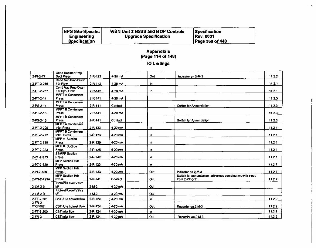
NPG Site-Specific WBN Unit 2 NSSS and BOP Controls SpecificationEngineering Upgrade Specification Rev. 0001Specification Page 360 of 440
Appendix E(Page 1114 of 148)
10 Listings
Cond Booster Pmp2-PI-2-77 Suct Press 2-R-123 4-20 mA Out Indicator on 2-M-3 11.2.2
Cond Vac Pmp Disch2-FT-2-256 Fi'r Flow 2-R-142 4-20 mA In 11.2.1
Cond Vac Pmp Disch2-FT-2-257 Fltr Byp Flow 2-R-142 4-20 mA In 11.2.1
MFPT A Condenser2-PT-2-14 Press 2-R.141 4-20 mA 11.2.3
MFPT A Condenser2-PS-2-1t4 Press 2-R-141 Contact Switch for Annunciation 11.2.3
MFPT B Condenser2-PT-2-15 Press 2-R-141 4-20 mA 11.2.3
MFPT B Condenser2-PS-2-15 Press 2-R-141 Contact Switch for Annunciation 11.2.3
MFPT A Condenser2-PT-2-206 Inlet Press 2-R-1 23 4-20 mA In 11.2 1
MFPT B Condenser2-PT-2-212 Inlet Press 2---123 4-20 mA In 11.2.1
MFP A Suction2-PT-2-220 Press 2-R-125 4-20 mA In 11.2.1
MFP B Suction2-PT-2-223 Press 2-R-125 4-20 mA In 11.2.1
SBMFP Suction2-PT-2-273 Press 2-R-142 4-20 mA In 11.2.1
MFP Suction Hdr2-PT-2-129 Press 2-R-1 23 4-20 mA In 11.2.7
MFP Suction Hdr2-PI-2-129 Press 2-R-123 4-20 MA Out Indicator on 2-M-3 11.2-7
MFP Suction Hdr Switch for annunciation, arithmetic combination with input2-PS-2-129A Press 2-R-141 Contact Out from 2-PT-5-3I. 11.2-7
Hotwell Level Valve2-LM-2-3 I/P 2-M-2 4-20 mA Out
Hotwell Level Valve2-LM-2-9 liP 2-M-2 4-20 mA Out
2-FT-2-201 CST A to hotwell flow 2-R-124 4-20 mA In 11-2.22-FR-2-200P002 CST A to hotwell flow 2-R-124 4-20 mA Out Recorder on 2-M-3 11.2.2
2-FT-2-200 CST inlet flow 2-R-124 4-20 mA In 11.2.2
2-FR-2- CST inlet flow 2-R-124 4-20 mA Out Recorder on 2-M-3 11.2.2
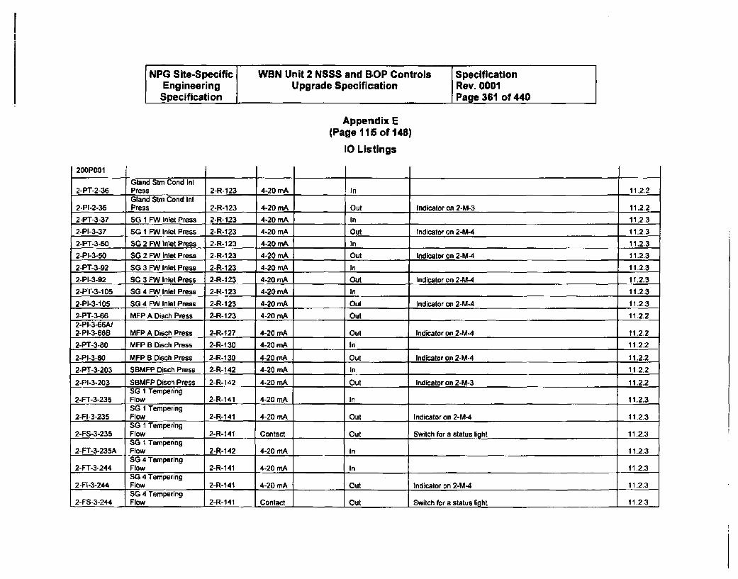
NPG Site-Specific WBN Unit 2 NSSS and BOP Controls SpecificationEngineering Upgrade Specification Rev. 0001Specification I Page 361 of 440
Appendix E(Page 115 of 148)
10 Listings
200P001
Gland Stm Cond Il2-PT-2-36 Press 2-R-123 4-20 mA In 11.2.2
Gland Stm Cond Inl2-PI-2-36 Press 2-R-123 4-20 mA Out Indicator on 2-M-3 11.2.2
2-PT-3-37 SG I FW Inlet Press 2-R-123 4-20 mA In 11.2.3
2-PI-3-37 SG I FW Inlet Press 2-R-123 4-20 mA Out Indicator on 2-M-4 11.2.3
2-PT-3-50 SG 2 FW Inlet Press 2-R-123 4-20 mA In 11.2.3
2-PI-3-50 SG 2 FW Inlet Press 2-R-123 4-20 mA Out Indicator on 2-M-4 11.2.3
2-PT-3-92 SO 3 FW Inlet Press 2-R-1 23 4-20 mA In 11.2.3
2-PI-3-92 SO 3 FW Inlet Press 2-R-123 4-20 mA Out Indicator on 2-M-4 11.2.3
2-PT-3-105 SG 4 FW Inlet Press 2-R-1 23 4-20 mA In 11.2.3
2-PI-3-105 SG 4 FW Inlet Press 2-R-123 4-20 mA Oul Indicator on 2-M-4 11.2.3
2-PT-3-66 MFPA Disch Press 2-R-123 4-20 mA Out 11.2.22-PI-3-66A/2-PI-3-66B MFP A Disch Press 2-R-127 4-20 mA Out Indicator oan 2-M-4 11.2.2
2-PT-3-80 MFP B Disch Press 2-fl-130 4-20 mA In 11.2.2
2-PI-3-80 MFP B Disch Press 2-R-130 4-20 mA Out Indicator on 2-M-4 11.2.2
2-PT-3-203 SBMFP Disch Press 2-R-142 4-20 mA In 11.2.2
2-PI-3-203 SBMFP Disch Press 2-R-142 4-20 rrA Out Indicator on 2-M-3 11.2.2SG I Tempering
2-FT-3-235 Flow 2-R-141 4-20 mA In 11.2.3SG 1 Tempering
2-FI-3-235 Flow 2-R-141 4-20 mA Out Indicator on 2-M-4 11.2.3SG 1 Tempering
2-FS-3-235 Flow 2-11-141 Contact Out Switch for a status light 11.2.3SG I Tempering
2-FT-3-235A Flow 2-R-142 4-20 mA In 11.2.3SG 4 Tempering
2-FT-3-244 Flow 2-R-141 4-20 mA In 11.2.3SG 4 Tempering
2-FI-3-244 Flow 2-R-141 4-20 mA Out Indicator on 2-M-4 11.2.3SG 4 Tempering
2-FS-3-244 Flow 2-R-141 Contact Out Switch for a status light 11.2.3
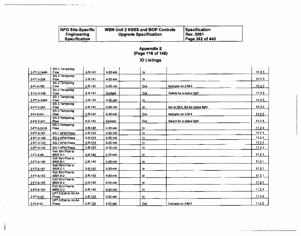
NPG Site-Specific WBN Unit 2 NSSS and BOP Controls SpecificationEngineering Upgrade Specification Rev. 0001Specification Page 362 of 440
Appendix E(Page 116 of 148)
10 Listings
2-FT-3-244ASG 4 TemperingFlow 14-20 mA2-R-142 In 11.2.3SG 2 Tempering
2-FT-3-238 Flow 2-R-141 4-20 mA In 11.2 3SG 2 Tempering
2-FI-3-238 Flow 2-R-141 4-20 mA Out Indicator on 2-M-4 11.2.3SG 2 Tempering
2-FS-3-238 Flow 2-R-141 Contact Out Switch for a status light 11-2.3SG 1 Tempering
2-FT-3-238A Flow 2-R-142 4-20 mnA In 11.2.3SG 3 Tempering
2-FT-3-241 Flow 2-R-141 4-20 mA In Ind on M-4, Sw for status light 11.2.3SG 3 Tempering
24-1-3-241 Flow 2-R-141 4-20 mA Out Indicator on 2-M-4 11.2.3SG 3 Tempering
2-FS-3-241 Flow 2-R-141 Contact Out Switch for a status light 11.2.3SG 3 Tempering
2-FT-3-241A Flow 2-R-142 4-20 mA In 11.2.3
2-PT-3-161 SG 1 AFW Press 2-R-123 4-20 mA In 11.2_1
2-PT-3-168 SG 4 AFW Press 2-R-123 4-20 mA In 11.2.1
2-PT-3-153 SG 2 AFW Press 2-R-123 4-20 mA In 11.2.1
2-PT-3-146 SG 3 AFW Press 2-R-123 4-20 mA In 11.2.1Exit Stm Flow to
2-FT-5-99 MSR A-1 2-R-142 4-20 mA In 11.2.1Extr Stm Flow to
2-FT-5-100 MSR B-1 2-R-142 4-20 mA In 11.2.1Extr Strn Flow to
2-FT-5-101" MSR C-1 2-R-142 4-20 mA In 11.2.1Extr Stm Flow to
2-FT-5-102 MSR A-2 2-R-142 4-20 mA In 11.2.1Extr Stm Flow to
2-FT-5-103 MSR 1-2 2-R-142 4-20 mA In 11.2.1Extr Stm Flow to
2-FT-5-104 MSR C-2 2-R-142 4-20 mA In 11.2.1LPT A Extr to Htr A4
2-PT-5-52 Press 2-R-123 4-20 mA In 11.2.2LPT A Extr to Htr A4
2-PI-5-52 Press 2-R-123 4-20 mA Out Indicator on 2-M-2 11.2.2
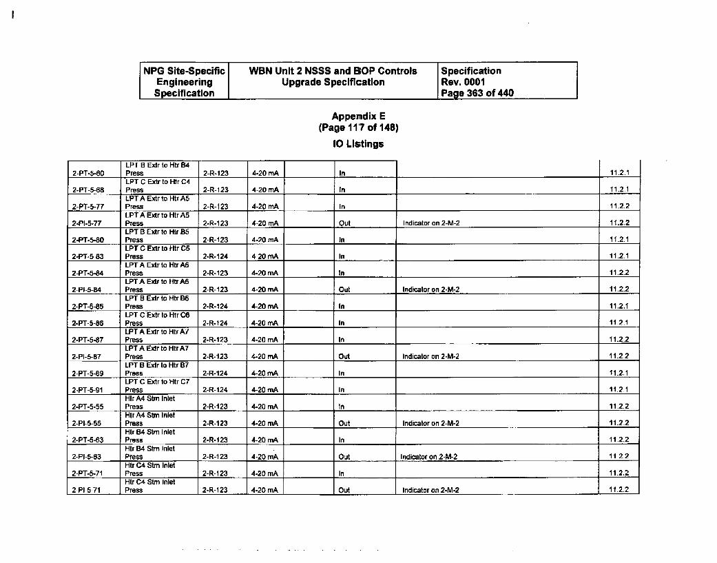
NPG Site-Specific WBN Unit 2 NSSS and BOP Controls SpecificationEngineering Upgrade Specification Rev. 0001Specification Page 363 of 440
Appemdix E(Page 117 of 148)
10 Listings
LPT U Extr to Htr B4Press 2-R-123 4-20 mA2-PT-5-AC In 11.2.1LPT C Extr to Htr C4
2-PT-5-68 Press 2-R-123 4-20 mA In 11,2.1LPT A Extr to Htr A5
2-PT-5-77 Press 2-R-123 4-20 mA In 11.2.2LPT A Extr to Htr A5
2-PI-5-77 Press 2-R-123 4-20 mA Out Indicator on 2-M-2 11.2.2LPT B Extr to H-r 85
2-PT-5-80 Press 2-R-1 23 4-20 mA In 11.2.1LPT C Extr to Htr C5
2-PT-5-83 Press 2-R-124 4-20 mA In 11.2.1LPT A Extr to Htr A6
2-PT-5-84 Press 2-R-123 4-20 mA In 11.2.2LPTA Extr to HtrA6
2-PI-5-84 Press 2-R-123 4-20 mA Out Indicator on 2-M-2 11.2.2LPT B Extr to Htr B6
2-PT-5-85 Press 2-R-124 4-20 mA In 11.2.1LPT C Extr to Htr C6
2-PT-5-86 Press 2-R-124 4-20 mA In 11.2.1LPT A Extr to Htr A7
2-PT-5-87 Press 2-R-123 4-20 mA In 11.2.2LPT A Extr to Htr A7
2-PI-5-87 Press 2-R-123 4-20 mA Out Indicator an 2-M-2 11.2.2LPT B Extr to Htr B7
2-PT-5-89 Press 2-R-124 4-20 mA In 11.2.1LPT C Extr to Htr C7
2-PT-5-91 Press 2-R-124 4-20 mA In 11.2.1Hir A4 Sim Inlet
2-PT-5-55 Press 2-R-123 4-20 mA In 11.2.2Hir A4 Sim Inlet
2-PI-5-55 Press 2-R-1 23 4-20 mA Out Indicator on 2-M-2 11.2.2Htr B4 Sim Inlet
2-PT-5-63 Press 2-1-M23 4-20 mA In 11.2.2Htr B4 Sirn Inlet
2-PI-5-63 Press 2-R-123 4-20 mA Out Indicator on 2-M-2 11.2.2Htr C4 Stm Inlet
2-PT-S-71 Press 2-R-123 4-20 mA In 11.2.2Htr C4 Stm Inlet
2-PI-5-71 Press 2-R-1 23 4-20 mA Out Indicator on 2-M-2 11.2.2
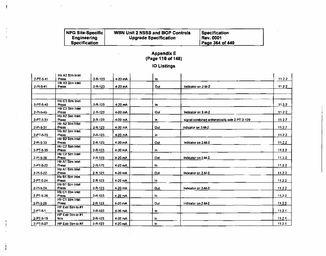
NPG Site-Specific WBN Unit 2 NSSS and BOP Controls SpecificationEngineering Upgrade Specification Rev. 0001Specification Page 364 of 440
Appendix E(Page 11 S of 148)
10 Listings
Htr A3 Stm InletPress 2-R-1232-PT-5-41 4-20 MA I In 11.2.2Htr A3 Stm Inlet
2-PI-5-41 Press 2-R-123 4-20 mA Out Indicator on 2-M-2 11.2.2
Htr C3 Stm Inlet2-PT-5-45 Press 2-R-123 4-20 mA In 11.2.2
Htr C3 Stm Inlet2-PI-5-45 Press 2-R-123 4-20 mA Out Indicator on 2-M-2 11.2.2
Htr A2 Stm Inlet2-PT-5-31 Press 2-R-1 23 4-20 mA In signal combined arithmetically with 2-PT-2-129 11.2.7
Htr A2 Stm Inlet
2-PI-5-31 Press 2-R-123 4-20 mA Out Indicator on 2-M-2 11.2.7Htr B2 Stm Inlet
2-PT-5-33 Press 2-R-123 4-20 mA In 11.2.2Htr 62 Stm Inlet
2-PI-5-33 Press 2-R-123 4-20 mA Out Indicator on 2-M-2 11.2.2Htr C2 Stm Inlet
2-PT-6-35 Press 2-R-123 4-20 mA In 11.2.2Htr C2 Stn Inlet
2-PI-5-35 Press 2-R-123 4-20 mA Out Indicator on 2-M-2 11.2.2Htr Al Stm Inlet
2-PT-5-22 Press 2-R-t23 4-20 mA In 11.2.2Htr Al Stm Inlet
2-PI-5-22 Press 2-R-123 4-20 mA Out Indicator on 2-M-2 11.2.2Htr B1 Stm Inlet
2-PT-5-24 Press 2-R-123 4-20 mA In 11-2.2Htr B1 Stm Inlet
2-PI-5-24 Press 2-R-123 4-20 mA Out Indicator on 2-M-2 11.2.2Htr C1 Stm Inlet
2-PT-5-26 Press 2-R-123 4-20 mA In 11.2.2Htr C1 Stm Inlet
2-PI-5-26 Press 2-R-123 4-20 mA Out Indicator on 2-M-2 11-2.2HP Extr Stm to #1
2-PT-5-1 htrs 2-R-123 4-20 mA In 11.2.1HP Extr Stm to #1
2-PT-5-19 hMrs 2-R-123 4-20 mA In 11.2.12-PT-5-27 HP Extr Stm to #2 2-R-123 4-20 mA In 11.2.1
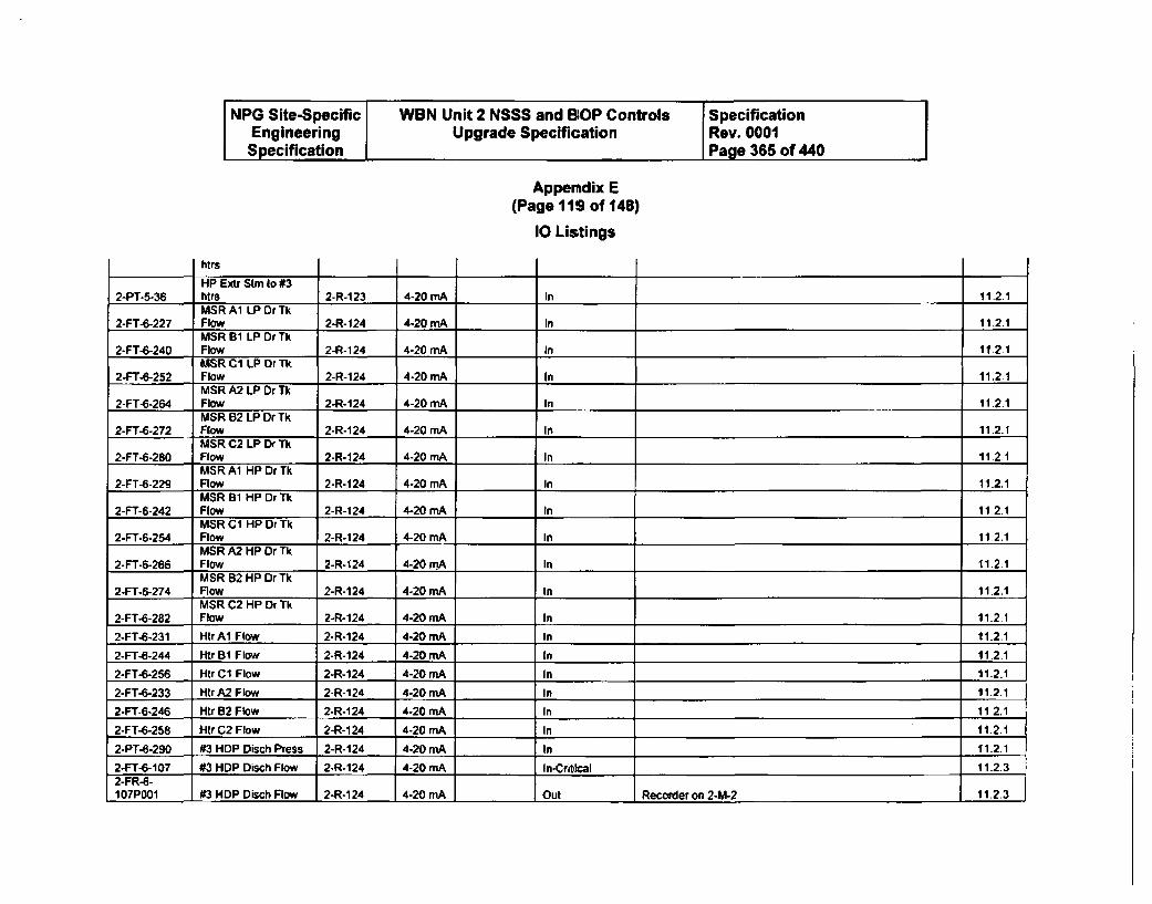
NPG Site-Specific WBN Unit 2 NSSS and BOP Controls SpecificationEngineering Upgrade Specification Rev. 0001Specification Page 365 of 440
Appendix E(Page 11S of 148)
10 Lis;tings
htrs
HP Extr Stm (o #32-PT-5-36 Flrs 2-R-123 4-20 mA In 11.2.1
MSR Aw LP Dr Tk2-FT-6-227 Flow 2-R- 124 4-20 mA In 11.2.1
MSR A1 LP Dr Tk2-FT-6-240 Flow 2-R-124 4-20 mA In 11.2.1
MSR C1 LP Dr Tk2-FT-6-252 Flow 2-R-124 4.20 mA In 11.2.1
MSR A2 LP Dr Tk2-FT-6-264 Flow 2-R-124 4-20 mA In 11.2.1
MSR B2 LP Dr Tk2-FT-6-272 Flow 2-R-124 4-20 mA In 11.2.1
MSR C2 LP Dr Tk
2-FT-6-280 Flow 2-R-124 4-20 mA In 11.2.1MSR A1 HP Dr Tk
2-FT-6-229 Flow 2-R-124 4-20 mA In 11.2.1MSR 31 HP Dr Tk
2-FT-6-242 Flaw 2-R-124 4-20 mA In 11.2.1MSRB1 HPDrTk
2-FT-6-254 Row 2-R-124 4-20 mA In 11.2.1MSR A2 HP Dr Tk
2-FT-6-266 Flow 2-R-124 4-20 mA In 11.2.1MSR B2 HP Dr Tk
2-FT-6-274 trow 2-R-124 4-20 mA In 11.2.1MSR C2 HP Dr Tk
2-FT-6-282 Flow 2-R-124 4-20 mA In 11.2.1
2-FT-6-231 HtrMA Flow 2-R-124 4-20 mA In 11.2.1
2-FT-6-244 Htr B0 Flow 2-R-124 4-20 mA In 11.2.1
2-FT-6-256 Htr C1 Flow 2-R-124 4-20 mA In 11.2.12-FT-6-233 Htr A2 Flow 2-R-124 4-20 rnA in 11.2.1
2-FT-6-246 Htr B2 Flow 2-R-124 4-20 mA In 11 2.1
2-FT-6-258 Htr C2 Flow 2-R-124 4-20 rnA In 11.2.1
2-PT-6-290 #3 HDP Disch Press 2-R-124 4-20 mA In 11.2.1
2-FT-6-107 #3 HDP Disch Flow 2-R-124 4-20 mA In-Critk.al 11.2.32-FR-6-107P001 #3 HDP Disch Flow 2-R-124 4-20 mA Out Recorder on 2-h&2 11.2.3
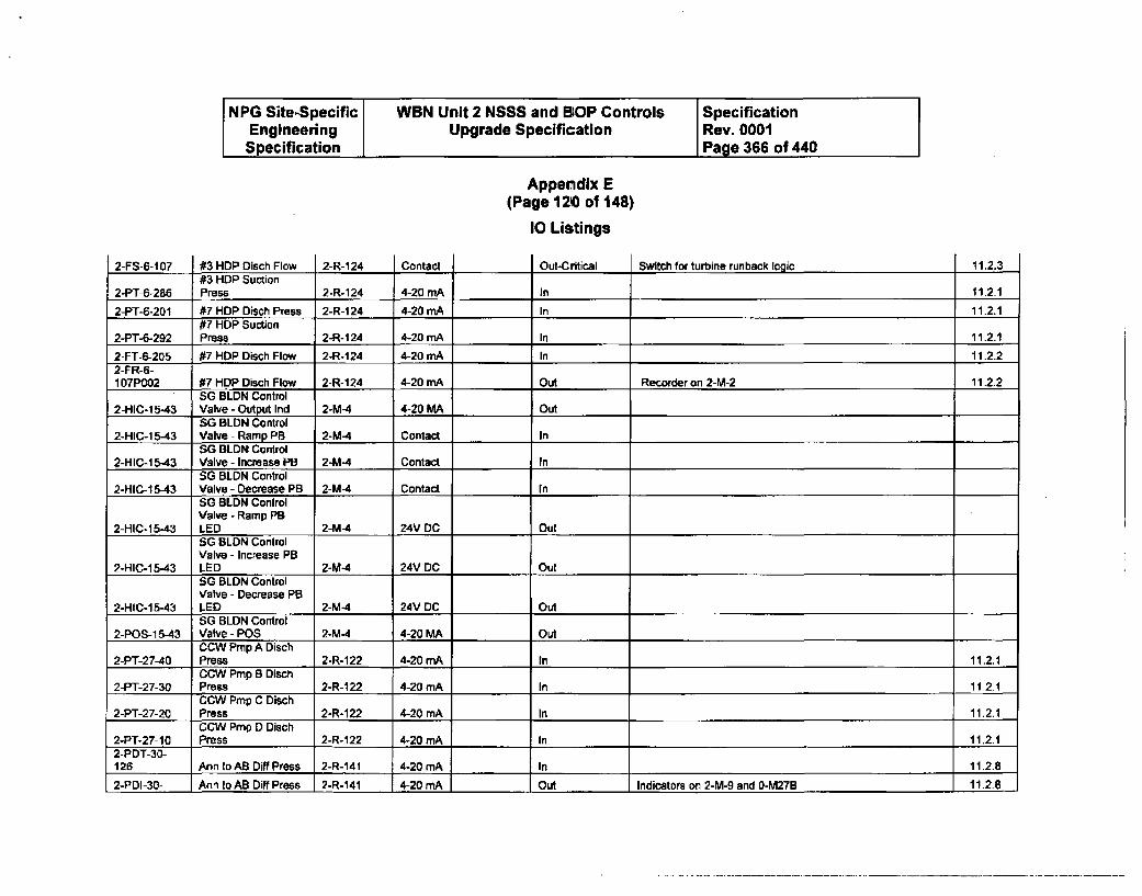
NPG Site-Specific J WBN Unit 2 NSSS and BOP Controls SpecificationEngineering Upgrade Specification Rev. 0001Specification Page 366 of 440
Appendix E(Page 1210 of 148)
I Listings
2-FS-6-107 #3 HDP Disch Flow 2-R-124 Contact Out-Critical Switch for turbine runback lbaic 11.2.3#3 HDP Suction
2-PT-6-286 Press 2-R-124 4-20 mA In 11.2.1
2-PT-5-201 #7 HDP Disch Press 2-R-124 4-20 mA In 11.2.1#7 HDP Suction
2-PT-6-292 Press 2-R-124 4-20 mA In 11-2-1
2-FT-6-205 #7 HDP Disch Flow 2-R-124 4-20 mA In 11.2.22-FR-6-107P002 #7 HDP Disch Flow 2-R-124 4-20 mA Out Recorder on 2-M-2 11.2.2
SG BLDN Control2-HIC-15.43 Valve - Output Ind 2-M-4 4-20 MA Out
SG BLDN Control2-HIC-1 5-43 Valve - Ramp PB 2-M-4 Contact In
SG BLDN Control2-HIC-15-43 Valve - Increase PB 2-M-4 Contact In
SG BLDN Control2-HIC-1 5-43 Valve - Decrease PB 2-M-4 Contact In
SG BLDN ControlValve - Ramp PB
2-HIC-15-43 LED 2-M4 24V DC OutSG BLDN ControlValve - Increase PB
2-HIC-15-43 LED 2-M-4 24V DC OutSG BLDN ControlValve - Decrease PB
2-HIC-15-43 LED 2-M-4 24V DC OutSG BLDN Control
2-POS-1 5-43 Valve - POS 2-M-4 4-20 MA OutCCW Pmp A Disch
2-PT-27-40 Press 2-R-122 4-20 mA In 11.2.1CCW Pmp 8 Disch
2-PT-27-30 Press 2-R-122 4-20 mA In 11.2.1CCW Prmp C Disch
2-PT-27-20 Press 2-R-1 22 4-20 rnA In 11.2.1CCW Pmp D Disch
2-PT-27-10 Press 2-R-122 4-20 mA In 11.2.12-PDT-30-126 Ann toAB Diff Press 2-R-141 4-20 mA In 11.2.8
2-PDI-30- Ann toAB Diff Press 2-R-141 4-20 rmA Out Indicators on 2-M-9 and 0-M27B 11.2.8
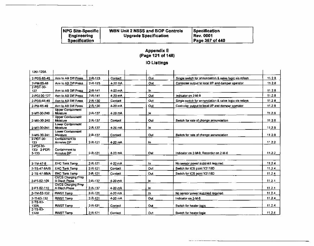
NPG Site-Specific WBN Unit 2 NSSS and BOP Controls SpecificationEngineering Upgrade Specification Rev. 0001Specification Page 367 of 440
Appendix E(Page 121 of 148)
10 Listings
126/-126A
2-PDS-65-48 Ann to AB D1ff Press 2-R-1 23 Contact Out Single switch for annunciation & valve logic via relays 11.2.8
2-PM-65-48 Ann to AB Diff Press 2-R-123 4-20 mA Out Controller output to local I/P and damper operator 11.2.8
2-PDT-30-127 Ann to AB Diff Press 2-R-141 4-20 mA In 11.2.8
2-PDI-30-127 Ann to AB Diff Press 2-R-141 4-20 mA Out Indicator on 2-M-9 11.2.8
2-PDS-65-49 Ann to AB Diff Press 2-R-130 Contact Out Single switch for annunciation & valve logic via relays 11.2.8
2-PM-65-49 Ann to AB Diff Press 2-R-1 30 4-20 mA Out Controller output to local I/P and damper operator 11.2.8
Upper Containment2-MT-30-240 Moisture 2-R-1 37 4-20 mA In 11-2.6
Upper Containment2-MS-30-240 Moisture 2-R-1 37 Contact Out Switch for rate of change annunciation 11.2.6
Lower Containment2-MT-30-241 Moisture 2-R-1 37 4-20 MA In 11.2.6
Lower Containment2-MS.30-241 Moisture 2-R-1_37 Contact Out Switch for rate of change annunciation 11.2.6
2-PDT-30- Containment to133 Annulus DP 2-R-121 4-20 mA In 11-2.2
2-PDI-30-133/ 2-PDR- Containmentto3-133 Annulus DP 2-R-121 4-20 mA I Out Indicator on 2-M-9, Recorder on 2-M-6 11.2.2
2-TM-47-8 EHC Tank Temp 2-R-121 4-20 mA In No sensor power supplied required. 11.2.4
2-TS-47-OA/B EHC Tank Temp 2-R-121 Contact Out Switch for ICS point Y2118D 11.2.4
2-TS-47-8B/A EHC Tank Temp 2-R- 121 Contact Out Switch for ICS point Y21i180 11.2.4
CVCS Charging Pmp2-PT-62-1 06 B Disch Press 2-R-1 37 4-20 mA In 11.2.1
CVCS Charging Pmp2-PT-62-110 A Dlsch Press 2-R-137 4-20 mA In 11.2.1
2-TM-63-132 RWST Temp 2-R-121 4-20 mA In No sensor power supplied required. 11.2.4
2-TI-63-132 RWST Temp 2-R-121 4-20 mA Out Indicator on 2-M-6 11.2.4
2-TS-63-132A RWSTTemp 2-R-121 Contact Out Switch for heater logic 11.2.4
2-TS-63-132B RWST Ternp 2-R-121 Contact Out Switch for heater logic 11.2.4
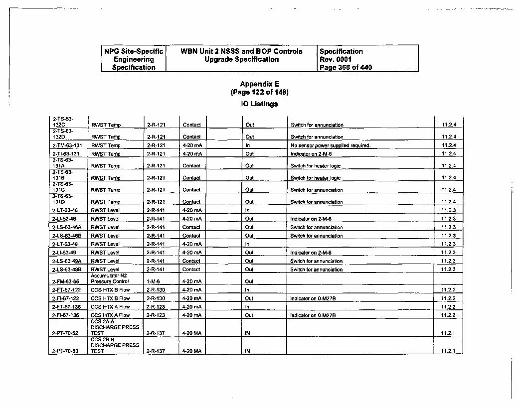
NPG Site-Specific WBN Unit 2 NSSS and BOP Controls SpecificationEngineering Upgrade Specification Rev. 0001Specification Page 368 of 440
Appendix E(Page 122 of 148)
10 Listings
2-TS-63-CIRICT Thmn •-•.4")1 C'•i .9 Q:uitrk h .. ~ o..•n.rin in, tII 9
4 - Q- f --. #;. C124
2-TS-63-1320 RWST Temp 2-R-121 Contact Out Switch for annunciation 11.2.4
2-TM-63-131 RWST Temp 2-R-121 4-20 mA In No sensor power supplied required. 11.2.4
2-TI-63-131 RWST Temp 2-R-121 4-20 mA Out Indicator on 2-M-6 11.2.42-TS-63-131A RWST Tamp 2-R-121 Contact Out Switch for heater logic 11.2.42-TS-63-131B RWST Temp 2-R-121 Contact Out Switch for heater logic 11.2.42-TS-63-131C RWST Tamp 2-R-121 Contact Out Switch for annunciation 11.2.42-TS-63-1310 RWST Temp 2-R-121 Contact Out Switch for annunciation 11.2.4
2-LT-63-46 RWST Level 2-R-141 4-20 mA In 11.2,3
2-LI-63-46 RWST Level 2-R-141 4-20 mA Out Indicator on 2-M-6 11.2.3
2-LS-63-46A RWST Level 2-R-141 Contact Out Switch for annunciation 11.2.3
2-LS-63-46B RWST Level 2-R-141 Contact Out Switch for annunciation 11.2-3
2-LT-63-49 RWST Level 2-R-141 4-20 mA In 11-2.3
2-LI-63-49 RWST Level 2-R-141 4-20 mA Out Indicator on 2-M-6 11.2.3
2-LS-63-49A RWST Level 2-R-141 Contact Out Switch for annunciation 11.2.3
2-LS-63-49B RWST Level 2-R-141 Contact Out Switch for annunciation 11.2.3Accumulator N2
2-FM-63-65 Pressure Control 1-M-6 4-20 mA Out
2-FT-67-122 CCS HTX B Flow 2-R-130 4-20 mA In 11.2.2
2-Fl-67-122 CCS HTX B Flow 2-R-130 4-20 mA Out Indicator on 0-M27B 11.2.2
2-FT-67-136 CCS HTX A Flow 2-R-123 4-20 mA In 11.2.2
2-FI-67-136 CCS HTX A Flow 2-R-123 4-20 mA Out Indicator on 0-M27B 11.2.2C0S 2A-ADISCHARGE PRESS
2-PT-70-52 TEST 2-R- 137 4-20 MA IN 11.2.1CCS 2B-BDISCHARGE PRESS
2-PT-70-53 TEST 2-R-137 4-20 MA IN 11.2.1
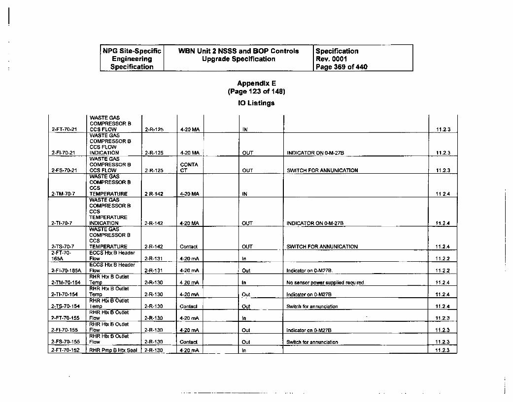
NPG Site-Specific WBN Unit 2 NSSS and BOP Controls SpecificationEngineering Upgrade Specification Rev. 0001Specification Page 369 of 440
Appemdix E(Page 12:3 of 148)
10 Listings
WASTE GASCOMPRESSOR BCCS FLOW 11.2.32-FT-70-21 2-R-125 4-20 MA INWASTE GASCOMPRESSOR BCCS FLOW
2-FI-70-21 INDICATION 2-R-125 4-20 MA OUT INDICATOR ON 0-M-27B 11.2.3WASTE GASCOMPRESSOR B CONTA
2-FS-70-21 CCS FLOW 2-R-1 25 CT OUT SWITCH FOR ANNUNICATION 11.2.3WASTE GASCOMPRESSOR BCCS
2-TM-70-7 TEMPERATURE 2-R-142 4-20 MA IN 11.2.4WASTE GASCOMPRESSOR BCCSTEMPERATURE
2-TI-70-7 INDICATION 2-R-142 4-20 MA OUT INDICATOR ON 0-M-27B 11-2.4WASTE GASCOMPRESSOR BCCS
2-TS-70-7 TEMPERATURE 2-R-142 Contact OUT SWITCH FOR ANNUNICATION 11.2.42-FT-70- ECCS Htx B Header165A Flow 2-R-131 4-20 mA In 11.2.2
ECCS Hix B Header2-Fl-70-15A Flow 2-R-1 31 4-20 mA Out Indicator on 0-M27B. 11.2.2
RHR Htx B Outlet2-TM-70-154 Temp 2-R-130 4-20 mA -- In No sensor power supplied required 11.2.4
RHR Htx B Outlet2-TI-70-154 Temp 2-R-130 4-20 mA Out Indicator on 0-M27B 11.2.4
RHR Htx B Outlet2-TS-70-154 Temp 2-R-130 Contact Out Switch for annunciation 11.2.4
RHR Htx B Outlet2-FT-70-155 Flow 2-R-130 4-20 mA In 11.2.3
RHR Htx B Outlet2-FI-70-155 Flow 2-R-130 4-20 mA Out Indicator on 0-M27B 11.2.3
RHR Htx B Outlet2-FS-70-155 Flow 2-R-130 Contact Out Switch for annunciation 11.2.3
2-FT-70-152 RHR Pmp B Htx Seal 2-R-130 4-20 mA In 11.2.3
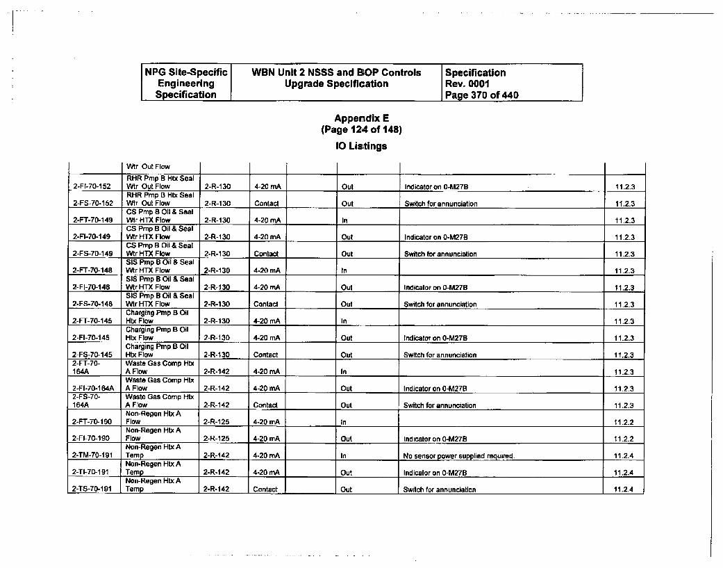
NPG Site-Specific WBN Unit 2 NSSS and BOP Controls SpecificationEngineering Upgrade Specification Rev. 0001Specification Page 370 of 440
Appendix E(Page 124 of 148)
10 Lis;tings
Wtr Out Flow
RHR Pmp B Htx Seal2-FI-70-152 Wtr Out Flow 2-R-130 4-20 mA Out Indicator on 0-M27B 11.2.3
RHR Pmp B Htx Seal2-FS-70-152 Wtr Out Flow 2-R-130 Contact Out Switch for annunciation 11.2.3
CS Pmp B Oil & Seal2-FT-70-149 WIr HTX Flow 2-R-130 4-20 mA In 11.2.3
CS Prnp B Oil & Seal2-FI-70-149 Wtr HTX Flow 2-R-1 30 4-20 rnA Out Indicator on 0-M27B 11.2.3
CS Pmp B Oil & Seal2-FS-70-149 Wtr HTX Flow 2-R-130 Contact Out Switch for annunciation 11.2.3
SIS Pmp B Oil & Seal2-FT-70-148 Wtr HTX Flow 2-R-130 4-20 mA In 11.23
SIS Pmp B Oil & Seal2-FI-70-148 Wtr HTX Flow 2-R-130 4-20 mA Out Indicator on 0-M27B 11.2.3
SIS Pmp B Oil & Seal2-FS-70-148 Wtr HTX Flow 2-R-130 Contact Out Switch for annunciation 11.2.3
Charging Pmp B Oil2-FT-70-145 Htx Flow 2-R-130 4-20 mA In 11.2.3
Charging Pmp B Oil2-FI-70-145 Htx Flow 2-R-130 4-20 mA Out Indicator on 0-M27B 11.2.3
Charging Prnp B Oil2-FS-70-145 Htx Flow 2-R-130 Contact Out Switch for annunciation 11.2.32-FT-70- Waste Gas Comp Htx164A A Flow 2-R-142 4-20 mA In 11.2.3
Waste Gas Comp Htx2-FI-70-164A A Flow 2-R-142 4-20 mA Out Indicator on 0-M27B 11.2-32-FS-70- Waste Gas Coamp Htx164A A Flow 2-R-142 Contact Out Switch for annunciation 11.2.3
Non-Regen Htx A2-FT-70-190 Flow 2-R-125 4-20 mA In 112.2
Non-Regen Htx A2-FI-70-190 Flow 2-R-125 4-20 mA Out Indicator on 0-M27B 11.2.2
Non-Regen Htx A2-TM-70-191 Temp 2-R-142 4-20 mA In No sensor power supplied required. 112.4
Non-Regen Htx A2-TI-70-191 Temp 2-R-142 4-20 mA Out Indicator on 0-M27B 11.2.4
Non-Regen Htx A2-TS-70-191 Temp 2-R-142 Contact Out Switch for annunciation 11.2.4
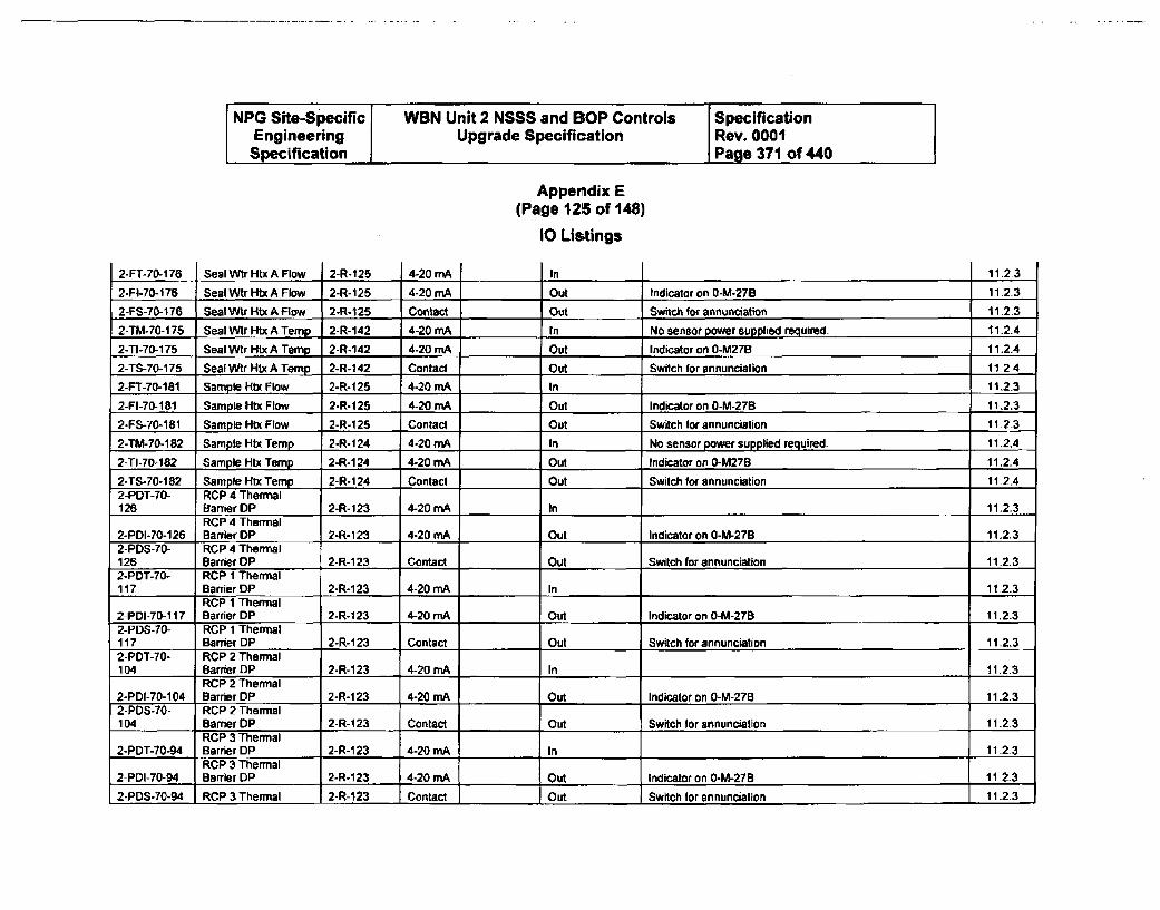
NPG Site-Specific WBN Unit 2 NSSS and BIOP Controls SpecificationEngineering Upgrade Specification Rev. 0001Specification Page 371 of 440
Appendix E(Page 125 of 148)
10 Lis;tings
4-20 mA I2-FT-70-1 76 Seal WtrHtx AFlow I2-R-125 In 11.2.3
2-FI-70-176 Seal Wtr HtxA Flow 2-R-125 4-20 mA Out Indicator on 0-M-279 11.2.3
2-FS-70-176 Seal Wtr Htx A Flow 2-R-125 Contact Out Switch for annunciation 11.2.32-TM-70-175 Seal Wtr Htx A Temp 2-R-142 4-20 mA In No sensor power supplied required. 11.2.4
2-TI-70-175 Seal Wtr Htx A Temp 2-R-142 4-20 mA Out Indicator on 0-M27B 11.2.4
2-TS-70-175 Seal Wtr Htx A Temp 2-R-142 Contact Out Switch for annunciation 11.2.4
2-FT-70-181 Sample Hb Flow 2-R-125 4-20 mA In 11,2.3
2-FI-70-181 Sample Htx Flow 2-R-125 4-20 mA Out Indicator on 0-M-27B 11.2.3
2-FS-70-181 Sample Htx Flow 2-R-125 Contact Out Switch for annunciation 11.2-3
2-TM-70-182 Sample Htx Temp 2-R-124 4-20 mA In No sensor power supplied required. 11.2.4
2-TI-70-182 Sample Htx Temp 2-R-124 4.20 mA Out Indicator on 0-M278 11.2.4
2-TS-70-182 Sample Htx Temp 2-R-I124 Contact Out Switch for annunciation 11.2.42-POT-70- RCP 4 Thermal126 Barrier DP 2-R-123 4-20 mA In 11.2.3
RCP 4 Thermal2-PDI-70-126 Barrier DP 2-R-123 4-20 mA Out Indicator on 0-M-27B 11.2.32-PDS-70- RCP 4 Thermal126 Barrier DP 2-R-123 Contact Out Switch for annunciation 11.2.32-PDT-7o- RCP 1 Thermal117 Barrier DP 2-R-123 4-20 mA In 11.2.3
RCP 1 Thermal2-PDI-70-117 Barrier DP 2-R-123 4-20 mA Out Indicator on O-M-27B 11.2.32-PDS-70- RCP 1 Thermal117 Barrier DP 2-R-123 Contact Out Switch for annunciation 11.2.32-PDT-70- RCP 2 Thermal104 Barrier DP 2-R-123 4-20 mA In 11.2.3
RCP 2 Thermal2-PDI-70-104 Barrier DP 2-R-123 4-20 mA Out Indicator on O-M-27B 11.2.32-PDS-70- RCP 2 Thermal104 Barrier DP 2-R-123 Contact Out Switch for annunciation 11.2.3
RCP 3 Thermal2-PDT-70-94 Barrier DP 2-R-123 4-20 mA In 11.2-3
RCP 3 Thermal2-PDI-70-94 Barrier DP 2-R-123 4-20 mA Out Indicator on O-M-27B 11 2.3
2-PDS-70-94 RCP 3 Thermal 2-R-123 Contact I Out Switch for annunciation 11.2.3
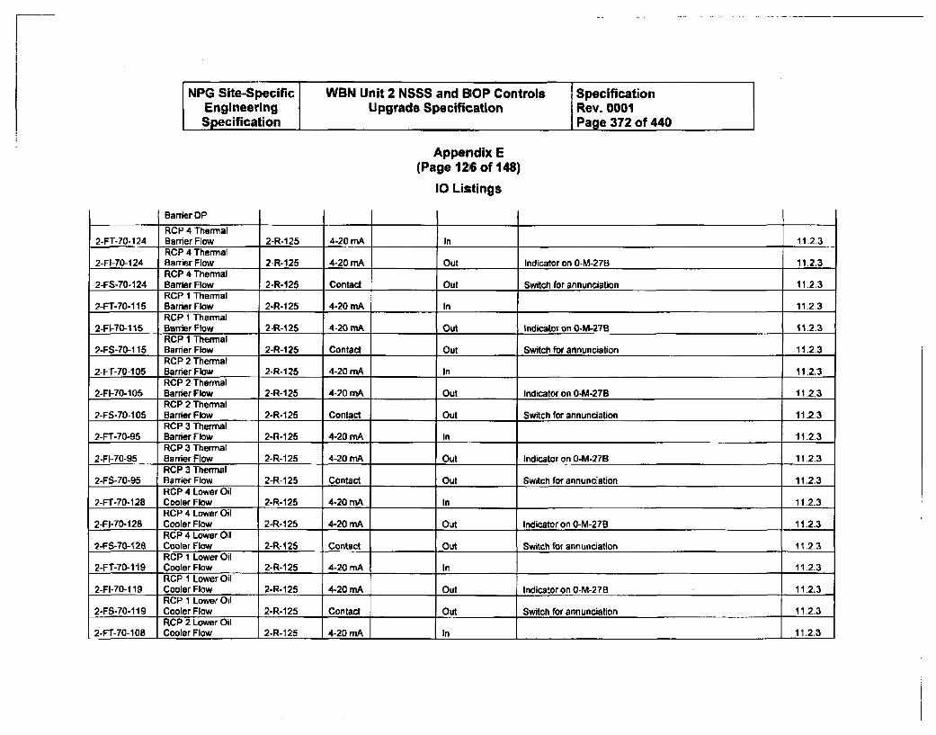
NPG Site-Specific WBN Unit 2 NSSS and BOP Controls SpecificationEngineering Upgrade Specification Rev. 0001Specification Page 372 of 440
Appendix E(Page 1216 of 148)
10 Listings
Barrier OP
RCP 4 Thermal2-FT-70-124 Banier Flow 2-R-125 4-20 mA In 11-2.3
RCP 4 Thermal2-FI-70-124 Barrier Flow 2-R-125 4-20 mA Out Indicator on 0-M-27B 11.2.3
RCP 4 Thermal2-FS-70-124 Barrier Flow 2-R-125 Contact Out Switch for annunciation 11.23
RCP 1 Thermal2-FT-70-115 Barrier Flow 2-R-125 4-20 mA In 11.2.3
RCP 1 Thermal2-Fl-70-115 Barrier Flow 2-R-125 4-20 mA Out Indicator on 0-M-27B 11.2.3
RCP 1 Thermal2-FS-70-1 15 Barier Flow 2-R-1 25 Contact Out Switch for annunciation 11.2.3
RCP 2 Thermal2-FT-70-105 Barrier Flow 2-R-125 4-20 mA In 11.2.3
RCP 2 Thermal2-FI-70-105 Barrier Flow 2-R-125 4-20 mA Out Indicator on 0-M-27B 11.2.3
RCP 2 Thermal2-FS-70-105 Barrier Flow 2-R-125 Contact Out Switch for annunciation 11-2.3
RCP 3 Thermal2-FT-70-95 Barrier Flow 2-R-125 4-20 mA In 11.2.3
RCP 3 Thermal2-FI-70-95 Barrier Flow 2-R-125 4-20 mA Out Indicator on 0-M-27B 11.2.3
RCP 3 Thermal2-FS-70-95 Barrier Flow 2-R-125 Contact Out Switch for annunciation 11.2.3
RCP 4 Lower Oil2-FT-70-128 Cooler Flow 2-R- 125 4-20 mA In 11.2.3
RCP 4 Lower Oil2-FI-70-128 Cooler Flow 2-R-125 4-20 mA Out Indicator on 0-M-27B 11.2.3
RCP 4 Lower Oil2-FS-70-128 Cooler Flow 2-R-1 25 Contact Out Switch for annunciation 11.2.3
RCP 1 Lower Oil2-FT-70-119 Cooler Flow 2-R-125 4-20 mA In 11.2.3
RCP I Lower Oil2-FI-70-119 Cooler Flow 2-R-125 4-20 mA Out Indicator on 0-M-27B 11.2.3
RCP 1 Lower Oil2-FS-70-1I9 Cooler Flow 2-R-125 Contact Out Switch for annunciation 11.2.3
RCP 2 Lower Oil2-FT-70-108 Cooler Flow 2-R-125 4-20 mA In 11.2.3
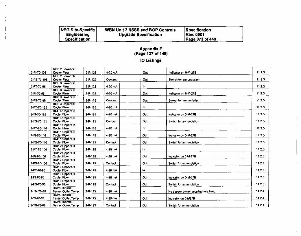
NPG Site-Specific WBN Unit 2 NSSS and BOP Controls SpecificationEngineering Upgrade Specification Rev. 0001Specification Page 373 of 440
Appendix E(Page 127 of 148)
10 Lis;tings
OutRCP 2 Lower Oil
ICooler Flaw2-Fl-70-108R 2-Rl-125 4-20 mA Indicator on 0-M-27R 11.2.3RCP 2 Lower Oil
2-FS-70-108 Cooler Flow 2-R-125 Contact Out Switch for annunciati6n 11.2.3RCP 3 Lower Oil
2-FT-70-98 Cooler Flow 2-R-1 25 4-20 mA In 11.2.3RCP 3 Lower Oil
2-FI-7T-S8 Cooler Flow 2-R-1 25 4-20 mA Out Indicator on 0-M-27B 11.2.3RCP 3 Lower Oil
2-FS-70-98 Cooler Flow 2-R-125 Contact Out Switch for annunciation 11.2.3RCP 4 Upper Oil
2-FT-70-125 Cooler Flow 2-R-125 4-20 mA In 11.2.3RCP 4 Upper Oil
2-FI-70-125 Cooler Flow 2-R-125 4-20 mA Out Indicator on 0-M-27B 11.2.3RCP 4 Upper Oil
2-FS-70-125 Cooler Flow 2-R-125 Contact Out Switch for annunciation 11.2.3RCP I Upper Oil
2-FT-70-116 Cooler Flow 2-R-125 4-20 mA In 11.2.3RCP 1 Upper Oil
2-FI-70-116 Cooler Flow 2-R-125 4-20 mA Out Indicator on 0-M-27B 11.2.3RCP 1 Upper Oil
2-FS-70-116 Cooler How 2-R-125 Contact Out Switch for annunciation 11.2.3RCP 2 Upper Oil
2-FT-70-1O6 Cooler Flow 2-R-125 4-20 mA In 11.2.3RCP 2 Upper Oil
2-Fl-70-106 Cooler Flow 2-R-125 4-20 mA Out Indicator on 0-M-27B 11.2.3RCP 2 Upper Oil
2-FS-70-106 Cooler Flow 2-R-125 Contact Out Switch for annunciation 11.2.3RCP 3 Upper Oil
2-FT-70-96 Cooler Flow 2-R-125 4-20 mA In 11.2.3RCP 3 Upper Oil
2-FI-70-96 Cooler Flow 2-R-125 4-20 mA Out Indicator on 0-M-27B 11.2.3RCP 3 Upper Oil
2-FS-70-96 Cooler Flow 2-R-125 Contact- Out Switch for annunciation 11.2.3RCPs Thermal
2-TM-70-88 Barrier Outlet Temp 2-R- 123 4-20 mA In No sensor power supplied required. 11.2.4RCPs Thermal
2-TI-0-B8 Barrier Outlet Temp 2-R-123 4-20 mA Out Indicator on 0-M27B 11.2.4RCPs Thermal
2-TS-70-88 Barrier Outlet Temp 2-R-123 Contact Out Switch for annunciation 11.2.4
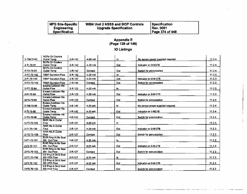
NPG Site-Specific WBN Unit 2 NSSS and BIOP Controls SpecificationEngineering Upgrade Specification Rev. 0001Specification Page 374 of 440
Appendix E(Page 128 of 148)
10 Listings
2-TM-70-91RCPs Oil CoolersOutlet Temo 2-R-142 4-20 MA In No sensor Dower supolied reauired. 11.2.4RCPs Oil Coolers
2-TI-70-91 Outlet Temp 2-R-142 4-20 mA Out Indicator on 0-M27B 11.2.4RCPs Oil Coolers
2-TS-70-91 Outlet Temp 2-R-142 Contact Out Switch for annunciation 11.2.4
2-FT-70-142 TBBP Sunction Flow 2-R-142 4-20 mA In 11.2.3
2-FI-70-142 TBBP Sunction Flow 2-R-142 4-20 mA Out Indicator on 0-M-27B 11.2.3
2-FS-70-142 TBBP Sunction Flow 2-R-142 Contact Out Switch for annunciation 1123Excess Letdown Htx
2-FT-70-84 Outlet Flow 2-R-123 4-20 mA In 11.2.3Excess Letdown Htx
2-FI-70-84 Outlet Flow 2-R-123 4-20 mA Out Indicator on 0-M-27B 11.2.3Excess Letdown Htx
2-FS-70-84 Outlet Flow 2-R-123 Contact Out Switch for annunciation 11.2.3Excess Letdown Htx
2-TM-70-86 Outlet Temp 2-R-142 4-20 mA In No sensor power supplied required. 11.2.4Excess Letdown Htx
2-T"-70-86 Outlet Temp 2-R-142 4-20 mA Out Indicator on 0-M27B 11.2.4Excess Letdown Htx
2-TS-70-86 Outlet Temp 2-R-142 Contact Out Switch for annunciation 11.2.4RHR HltxA Outlet
2-FT-70-158 Flow 2-R-127 4-20 mA In 11.2.3RHR HIx A Outlet
2-FI-70-158 Flow 2-R-127 4-20 mA Out Indicator on 0-M-27B 11.2.3RHR HtxA Outlet
2-FS-70-158 Flow 2-R-127 Contact Out Switch for annunciation 11.2.3RHR Pmp A Htx Seal
2-FT-70-1 51 Wtr Out Flow 2-R-127 4-20 mA In 11.2.3RHR Pmp A Htx Seal
2-FI-70-151 Wtr Out Flow 2-R-127 4-20 mA Out Indicator on 0-M-27B 11.2.3RHR Pmp A Htx Seal
2-FS-70-151 Wtr Out Flow 2-R-127 Contact Out Switch for annunciation 11.2.3CS Prmp A Oil & Seal
2-FT-70-1 50 Wtr HTX Flow 2-R-127 4-20 rnA In 11.2.3CS Pmp A Oil & Seal
2-FI-70-150 Wtr HTX Flow 2-R-127 4-20 mA Out Indicator on 0-M-27B 11.2.3CS Prmp A Oil & Seal
2-FS-70-150 Wtr HTX Flow 2-R-127 Contact Out Switch for annunciation 11.2.3
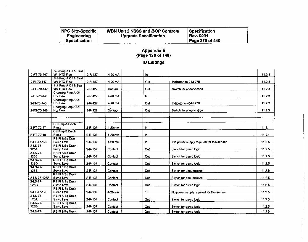
NPG Site-Specific WBN Unit 2 NSSS and BOP Controls SpecificationEngineering Upgrade Specification Rev. 0001Specification Page 375 of 440
Appendix E(Page 129 of 148)
10 Listings
SIS Pmp A Oil & SealWir HTX Flow2-FT-70-1 47 2-R-127 4-20 mA In 11.2.3SIS Pmp A Oil & Seal
2-FI-70-147 Wtr HTX Flow 2-R-127 4-20 mA Out Indicator on 0-M-27B 11.2.3SIS Pmp A Oil & Seal
2-FS-70-147 Wer HTX Flow 2-R-127 Contact Out Switch for annunciation 11.2.3Charging Pmp A Oil
2-FT-70-146 Htx Flow 2-R-127 4-20 mA In 11.2.3Charging Pmp A Oil
2-Ft-70-146 Htx Flow 2-R-127 4-20 mA Out Indicator on 0-M-27B 11.2.3Charging Pmp A Oil
2-FS-70-146 Htx Flow 2-R-127 Contact Out Switch for annunciation 11.2.3
CS Pmp A Diach2-PT-72-17 Press 2-R-137 4-20 mA In 11.2.1
CS Prp B Disch2-PT-72-18 Press 2-R-1 37 4-20 rnA In 11.2.1
RB Fl & Eq Drain2-LT-T7-125 Sump Level 2-R-137 4-20 mA In No power supply required for this sensor. 11.2.52-LS-77- RB Fl & Eq Drain125A Sump Level 2-R-137 Contact Out Switch for pump logic 11.2.52-LS-77- RB Fl & Eq Drain125B Sump Level 2-R-137 Contact Out Switch for pump logic 11.2.52-LS-77- RB Fl & Eq Drain125D Sump Level 2-R-137 Contact Out Switch for pump logic 11.2.52-LS-77- RB Fl & Eq Drain125E Sump Level 2-R-137 Contact Out Switch for annunciation 11.2.5
RB FI & Eq Drain2-LS-77-125F Sump Level 2-R-137 Contact Out Switch for annunciation 11.2.52-LS-77- RB FL & Eq Drain1250 Sump Level 2-R-137 Contact Out Switch for pump logic 11.2.5
RB FI & Eq Drain2-LT-77-126 Sump Level 2-R-137 4-20 mA In No power supply required for this sensor. 11.2.52-LS-77- RB Fl & Eq Drain126A Sump Level 2-R-1 37 Contact Out Switch for pump logic 11.2-52-LS-77- RB Fl & Eq Drain126B Sump Level 2-R-1 37 Contact Out Switch for pump logic 11.2.5
2-LS-77- RB Fl & Eq Drain 2-R-137 Contact Out Switch for pump logic 11.2.5
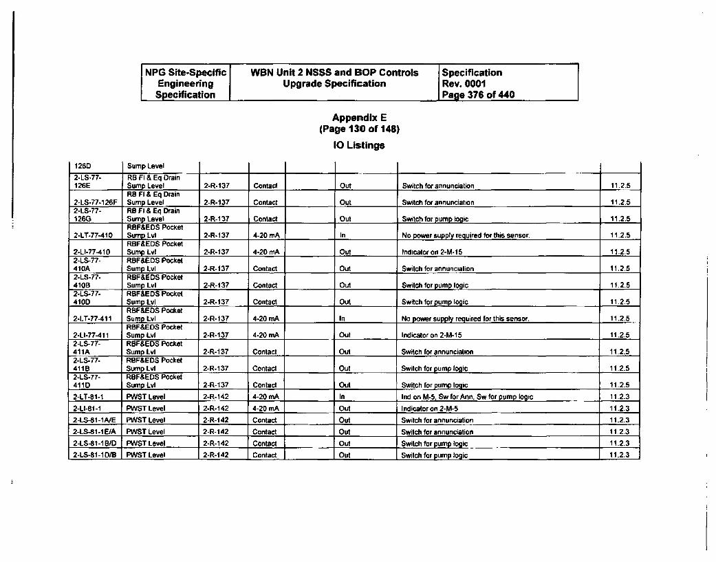
NPG Site-Specific WBN Unit 2 NSSS and BOP Controls SpecificationEngineering Upgrade Specification Rev. 0001Specification I Page 376 of 440
Appendix E(Page 1310 of 148)
10 Listings
126D Sump Level
2-LS-77- RB Fl & Eq Drain126E Sump Level 2-R-137 Contact Out Switch for annunciation 11.2.5
RB FI & Eq Drain2-LS-77-126F Sump Level 2-R-137 Contact Out Switch for annunciation 11.2.52-LS-77- RB Fl & Eq Drain126G Sump Level 2-R-137 Contact Out Switch for pump logic 11.2.5
RBF&EDS Pocket2-LT-77-410 Sump Lvi 2-R-137 4-20 mA In No power supply required for this sensor. 11.2.5
RBF&EDS Pocket2-LI-77-410 Sump Lvi 2-R-137 4-20 mA Out Indicator on 2-M-15 11.2.52-LS-77- RBF&EDS Pocket410A Sump Lvl 2-R-137 Contact Out Switch for annunciation 11.2.52-LS-77- RBF&EDS Pocket410B Sump Lvi 2-R-137 Contact Out Switch for pump logic 11.2.52-LS-77- RBF&EDS Pocket410D Sump Lvl 2-R-137 Contact Out Switch for pump logic 11.2.5
RBF&EDS Pocket2-LT-77-411 Sump Lvl 2-R-137 4-20 mA In No power suppl required for this sensor. 11.2.5
RBF&EDS Pocket2-LI-77-411 Sump Lvl 2-R-137 4-20 mA Out Indicator on 2-M-15 11.2.52-LS-77- RBF&EDS Pocket411A Sump Lvl 2-R-137 Contact Out Switch for annunciation 11.2.52-LS-77- RBF&EDS Pocket411B Sump Lvl 2-R-137 Contact Out Switch for pump logic 11.2.52-LS-77- RBF&EDS Pocket411D Sump LvI 2-R-137 Contact Out Switch for pump logic 11.2.5
2-LT-81-1 PWST Level 2-R-142 4-20 mA In Inrid onMA. Sw for Ann. Sw for pump logic 11.2.3
2-LI-81-1 PWST Level 2-R-142 4-20 mA Out Indicator on 2-M-5 11.2.3
2-LS-81-1A/E PWST Level 2-R-142 Contact Out Switch for annunciation 11-2.3
2-LS-81-1EIA PWST Level 2-R-142 Contact Out Switch for annunciation 11.2.3
2-LS-81-IBID PWST Level 2-R-142 Contact Out Switch for pump logic 11.2.3
2-L5-81-1D/B PWST Level 2-R-142 Contact Out Switch for pump logic 11.2.3
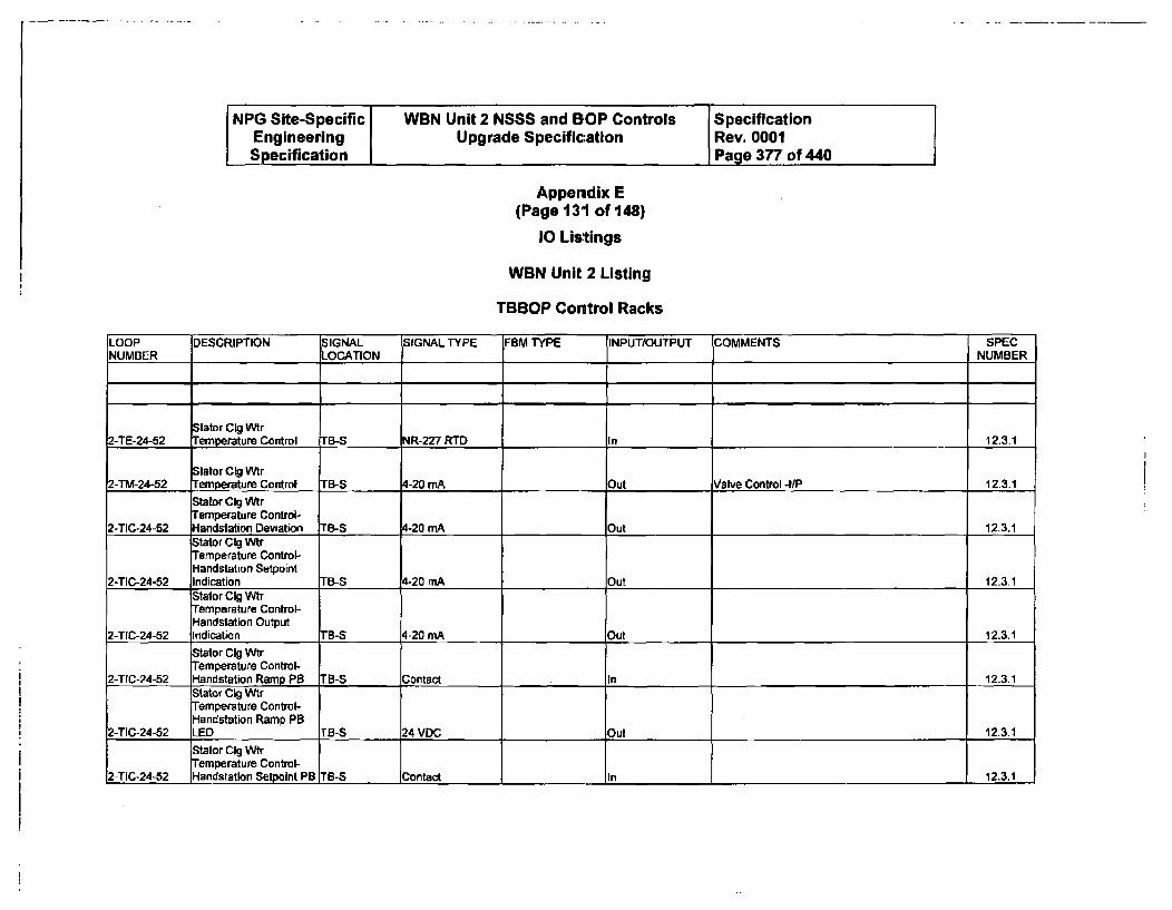
NPG Site-Specific WBN Unit 2 NSSS and BOP Controls SpecificationEngineering Upgrade Specification Rev. 0001Specification Page 377 of 440
Appendix E(Page 131 of 148)
10 Lis'tings
WBN Unit 2 Listing
TBBOP Control Racks
LOOP DESCRIPTION SIGNAL SIGNAL TYPE F8M TYPE INPUT/OUTPUT COMMENTS SPECNUMBER LOCATION NUMBER
Stator CIg Wtr2-TE-24-52 Temperature Control TB-S NR-227 RTD In 12.3.1
Stator Cig Wtr2-TM-24-52 Temperature Control TB-S 4-20 mA Out Valve Control -4/P 12.3.1
Stator C1g WtrTemperature Control-
2-TIC-24-52 Handstation Deviation TB-S 4-20 mA Out 12.3.1Stator CIg WtrTemperature Control-Handstation Setpoint
2-TIC-24-52 Indication TB-S 4-20 mA Out 12.3.1Stator Cig WtrTemperature Control-Handstation Output
2-TIC-24-52 Indication TB-S 4-20 mA Out 12.3.1
Stator CIg VtrTemperature Control-
2-TIC-24-52 Handstation Ramp PB TB-S Contact In 12.3.1Stator CGi WtrTemperature Control-Handstation Ramp PB
2-TIC-24-52 LED TB-S 24 VDC Out 12.3.1
Stator CIg WtrTemperature Control-
2-TIC-24-52 Handstation Setpoint PB TB-S Contact lin 12.3.1
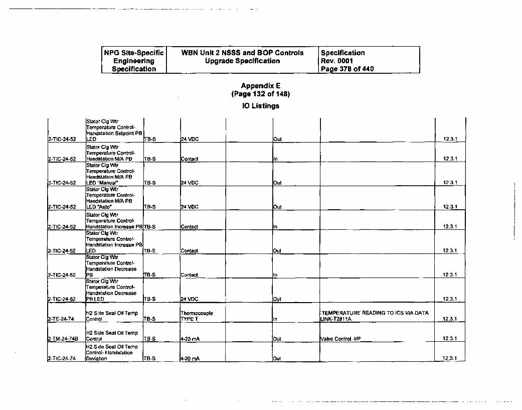
NPG Site-Specific WBN Unit 2 NSSS and BOP Controls SpecificationEngineering Upgrade Specification Rev. 0001Specification I Page 378 of 440
Appendix E(Page 132 of 148)
I0 Listings
Stator CIg WtrTemperature Control-Handstation Setpoint PB
2-TIC-24-52 LED TB-S 24 VDC Out 12.3.1
Stator CIg WtrTemperature Control-
2-TIC-24-52 landstation WA PB TB-S contact In 12.3.1Stator GIg WtrTemperalure Control-Handstation MIA PB
2-TIC-24-52 LED "Manual" TB-S 24 VDC Out 12-3.1Stator CIg WirTemperature Control-Handstation WA PB
2-TIC-24-52 LED Auto" TB-S 24 VDC out 12.3.1
Stator CIg WtrTemperature Control-
2-TIC-24-52 Handstation Increase PB "B-S Contact In 12.3.1Stator CIg WtrTemperature Control-Handstation Increase PB
2-TIC-24-52 LED TB-S Contact _Out 12.3.1Stator CIg WtrTemperature Control--landstation Decrease
2-TIC-24-52 PB TB-S Contact In 12 3.1Stator CIg WVrTemperature Control--andstation Decrease
2-TIC-24-52 PB LED TB-S 24 VDC Out 12.3.1
H12 Side Seal Oil Temp Thermocouple TEMPERATURE READING TO ICS VIA DATA2-TE-24-74 Control TB-S TYPE T In LINK-T2811A 12.3.1
H12 Side Seal Oil Temp2-TM-24-74B Control TB-S 4-20 mA Out Valve Control -I/P 12.3.1
H2 Side Seal Oil TempControl- Handstation
Z-TIC-24-74 Deviation TB-S 4-20 mA Out 12.3.1
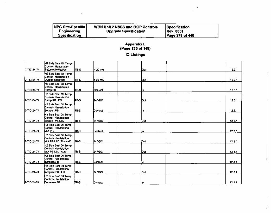
NPG Site-Specific WBN Unit 2 NSSS and BOP Controls SpecificationEngineering Upgrade Specification Rev. 0001Specification I Page 379 of 440
Appendix E(Page 133 of 148)
10 Listings
H2 Side Seal Oil TempControl- HandstationSelpoint Indication2-TIC-24-74 TB-S t-20 mA Dut 12.3.1H2 Side Seal Oil TempControl- Handstation
2-TIC-24-74 Output Indication TB-S 4-20 mA _Out 12.3.1
H2 Side Seal Oil TempControl- Handstation
2-TIC-24-74 Ramp PB TB-S Contact In 12-3-1
H2 Side Seal Oil TempControl- Handstation
2-TIC-24-74 Ramp PB LED TB-S 24 VDC Out 12.3.1
H2 Side Seal Oil TempControl- Handstation
2-TIC-24-74 Setpoint PB TB-S Contact In 12.3.1
H2 Side Seal Oil TempControl- Handstation
2-TIC-24-74 Setpoint PB LED TB-S 24 VDC Out 12.3.1
H2 Side Seal Oil TempControl- Handstation
2-TIC-24-74 M/A PB TB-S Contact In 12.3 1
K2 Side Seal Oil TempControl- Handsation
2-TIC-24-74 W/A PB LED "Manual" TB-S 24 VDC Out 12.3.1
H2 Side Seal Oil TempControl- Handstation
2-TIC-24-74 M/A PB LED "Auto" TB-S 24 VDC Out 12.3.1
H2 Side Seal Oil TempControl- Hlandstation
2-TIC-24-74 Increase PB TB-S Contact In 12.3.1
H2 Side Seal Oil TempControl- Handstation
2-TIC-24-74 Increase PB LED TB-S 24 VDC Out 12.3.1
H2 Side Seal Oil TempControl- Handstation
2-TIC-24-74 Decrease PB TB-S Contact In 12.3.1
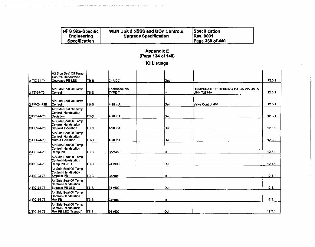
NPG Site-Specific WBN Unit 2 NSSS and BOP Controls SpecificationEngineering Upgrade Speciflcation Rev. 0001Specification Page 380 of 440
Appendix E(Page 134 of 148)
10 Listings
iut
H2 Side Seal Oil TempControl- HandstationDsecmase PR [ED2-TIC-24-74 TB -S 24 VDC 12.3.1
Air Side Seal Oil Temp Thermocouple TEMPERATURE READING TO ICS VIA DATA2-TE-24-73 Control TB-S TYPE T In LINK T281OA 12.3.1
Ar Side Seal Oil Temp2-TM-24-738 Control rB-S 4-20 mA Out Valve Control -U1P 12.3.1
Air Side Seal Oil TempControl- Handstation
2-TIC-24-73 Deviation TB-S 4-20 mA Out 12.3.1
Air Side Seal Oil TempControl- Handstation
2-TIC-24-73 Setpoint Indication TB-S 4-20 mA Out 12.3.1
Air Side Seal Oil TempControl- Handstation
Z-TIC-24-73 Output Indication . B-S 4-20 mA Out 12.3.1
Air Side Seat Oil TempControl- Handstation
2-TIC-24-73 Ramp PB rB-S Contact In 12.3.1
Air Side Seal Oil TempControl- Handstation
2-TIC-24-73 Ramp PB LED TB-S 24 VDC Out 12.3.1
Air Side Seal Oil TempControl- Handstation
2-TIC-24-73 Setpoint PB TB-S Contact In 12.3.1Air Side Seal Oil TempControl- Handstation
2-TIC-24-73 Setpolnt PB LED TB-S 24 VDC Out 12.3.1
Air Side Seal Oil TempControl- Handstation
2-TIC-24-73 M/A PB TB-S Contact In 12.3.1
Air Side Seal Oil TempControl- Handstation
,-TIC-24-73 M/A PB LED "Manual" TB-S 4 VDC Out 12.3.1
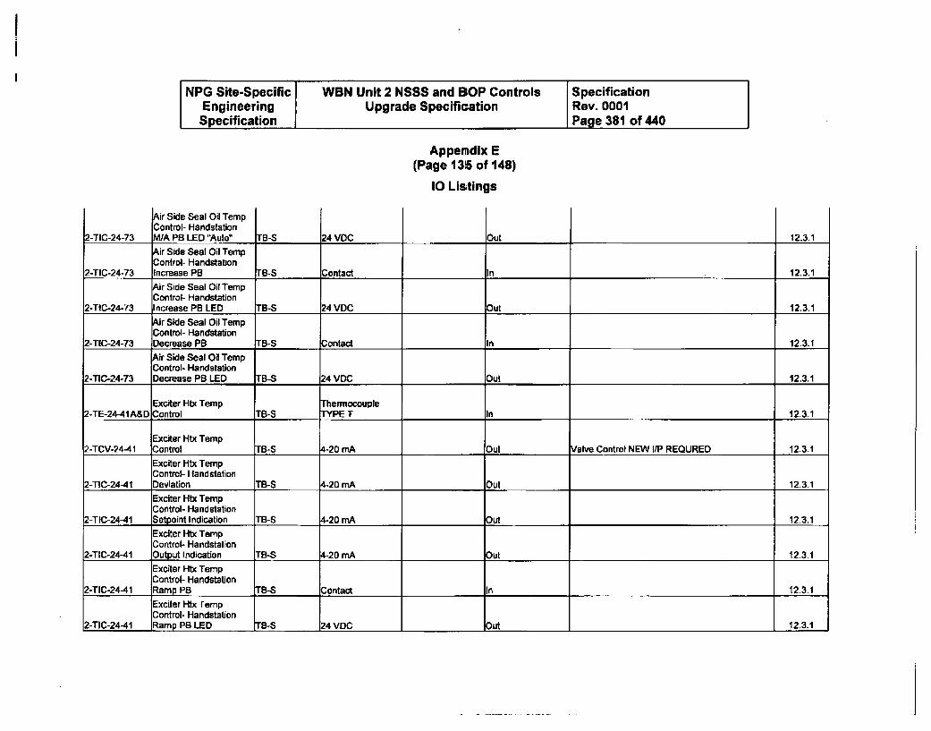
NPG Site-Specific WBN Unit 2 NSSS and BOP Controls SpecificationEngineering Upgrade Specification Rev. 0001Specification Page 381 of 440
Appeodix E(Page 135 of 148)
10 Listings
2-TIC-24-73
Air Side Seal Oil TempControl- HandstationM/A PB LED "Auto" rB-S 24 VOC Out 12.3.1
Air Side Seal Oil TempControl- Handstation
2-TIC-24-73 Increase PB rB-S Contact In 12.3.1
Air Side Seal Oil TempControl- Handstation
2-TIC-24-73 Increase PB LED FB-S 24 VDC Out 12.3.1
Air Side Seal Oil TempControl- Handstation
2-TIC-24-73 Decrease PB TB-S Contact In 12.3-1Air Side Seal Oil TempControl- Handstation
2-TIC-24-73 Decrease PB LED TB-S 24 VDC Out 12.3.1
Exciter Htx Temp Thermocouple2-TE-24-41A&D Control TB-S TPE T In 12.3.1
Exciter Htx Temp2-TCV-24-41 Control TB-S 4-20 mA Out Valve Control NEW UP REQURED 12.3.1
Exciter Htx TempControl- Handstation
2-TIC-24-41 Deviation TB-S 4-20 mA Out 12.3.1Exciter Htx TempControl- Handstation
2-TIC-24-41 Setpoint Indication TB-S 4-20 mA Out 12.3.1
Exciter Htx TempControl- Handstation
2-TIC-24-41 Output Indication TB-S 4-20 mA Out 12.3.1
Exciter Htx TempControl- Handstation
2-TIC-24-41 Ramp PB TB-S Contact In 12.3.1
Exciter Htx TempControl- Handstation
2-TIC-24-41 Ramp PB LED TB-S 24 VDC Out -.12.3.1
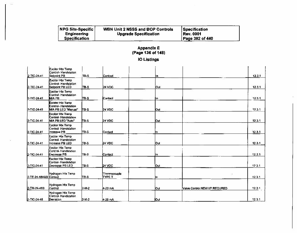
NPG Site-Specific WBN Unit 2 NSSS and BIOP Controls SpecificationEngineering Upgrade Specification Rev. 0001Specification Page 382 of 440
Appendix E(Page 136 of 148)
10 Lis;tings
Exciter Htx TempControl- HandstationSetooint PB2-TIC-24-41 T1B-S Contact In 12.3.1
Exciter Htx TempControl- Handstation
2-TIC-24-41 Setpoint PB LED TB-S 24 VDC Out 12.3.1
Exciter Htx TempControl- Handstation
2-TIC-24-41 M/A PB TB-S Contact In 12.3.1
Exciter Htx TampControl- Handstation
2-TIC-24-41 MIA PB LED "Manual" TB-S '24 VDC _ Out 12-3.1
Exciter HIx TampControl- Handstation
2-TIC-24-41 WA PB LED "Auto" TB-S 24 VDC Out 12.3.1
Exciter Htx TempControl- Handstation
2-TIC-24-41 Increase PB TB-S Contact In 12.3.1
Exciter Hix TempControl- Handstation
2-TIC-24-41 Increase PB LED TB-S 24 VDC: Out 12.3.1
Exciter Htx TampControl- Handstation
2-TIC-24-41 Decrease PB TB-S Contact In 12-3.1
Exciter Htx TempControl- Handstation
2-TIC-24-41 Decrease PB LED TB-S 24 VDC Out 12-3.1
Hydrogen Htx Temp Thermocouple2-TE-24-48A&B Control TB-S TYPE T In 12.3.1
Hydrogen Htx Temp2-TM-24-48B Control 2-M-2 4-20 mA Out Valve Control NEW lIP REQURED 12-3.1
Hydrogen Htx TampControl- Handstation
2-TIC-24-48 Devration 2-M-2 4-20 mA Out 12.3.1
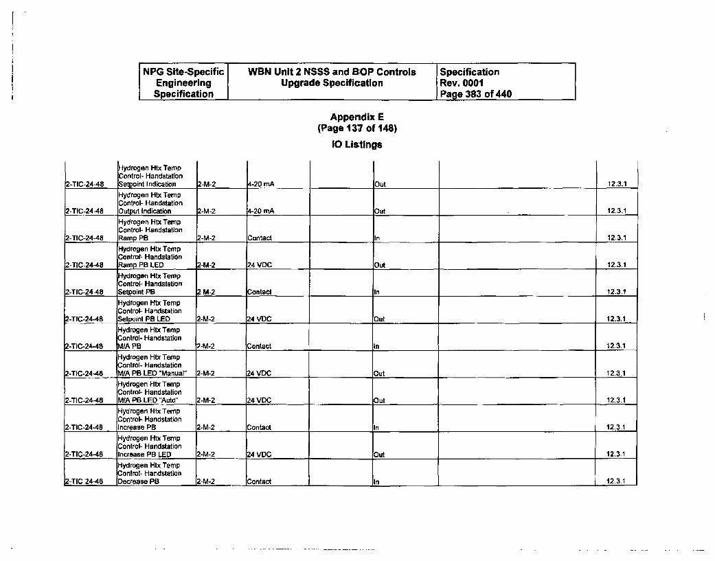
NPG Site-Specific WBN Unit 2 NSSS and BOP Controls SpecificationEngineering Upgrade Specification Rev. 0001Specification Page 383 of 440
Appendix E(Page 137 of 148)
10 Listings
Hydrogen Htx TempControl- HandstationSetocint Indication 4-20 mA2-TIC-24-4A 2-M-2 Out 12.3.1
Hydrogen Htx TempControl- Handstation
2-TIC-24-48 Output Indication 2-M-2 4-20 mA Out 12.3.1
Hydrogen Htx TempControl- Handstation
2-TIC-24-48 Ramp PB 2-M-2 Contact In 12.3.1
Hydrogen Htx TempControl- Handstation
2-TIC-24-48 Ramp PB LED 2-M-2 24 VDC Out 12.3.1
Hydrogen Htx TempContml- Handstation
Z-TIC-24-48 Setpoint PB 2-M-2 Contact In 12.3.1
Hydrogen HNx TempControl- Handstation
2-TIC-24-48 Setpoint PB LED 2-M-2 24 VDC Out 12.3.1
Hydrogen Htx TempControl- Handstation
2-TIC-24-48 MIA PB 2-M-2 Contact In 12.3.1
Hydrogen Htx TempControl- Handstation
2-TIC-24-48 WA PB LED "Manual" 2-M-2 24 VDC Out 12.3.1Hydrogen Htx TempControl- Handstation
2-TIC-24-48 MIA PB LED "Auto" 2-M-2 24 VDC Out 12.3.1
Hydrogen Htx TempControl- Handstation
2-TIC-24-48 Increase PB 2-M-2 Contact In 123.1
Hydrogen Htx TempControl- Handstation
2-TIC-24-48 Increase PB LED 2-M-2 24 VOC Out 12.3.1
Hydrogen Htx TempControl- Haandstation
2-TIC-24-48 Decrease P8 2-M-2 Contact _In 12.3.1
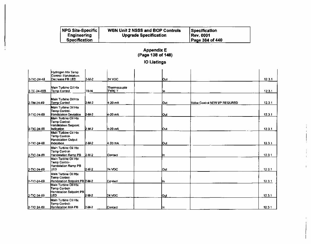
NPG Site-Specific WBN Unit 2 NSSS and BOP Controls SpecificationEngineering Upgrade Specification Rev. 0001Specification Page 384 of 440
Appendix E(Page 138 of 148)
10 Listings
Hydrogen Htx TempControl- HandstationDecrease PB LED 2-M-22-TIC-24-48 24 VDC Out 12.3.1
Main Turbine Oil Htx Thermocouple2-TE-24-69B Temp Control TB-N TYPE T In 12.3.1
Main Turbine Oil Htx2-TM-24-69 Temp Control 2-M-2 4-20 mA Out Valve Control NEW I/P REQURED 12.3.1
Main Turbine Oil Htxremp Control-
2-TIC-24-69 Handstation Deviation 2-M-2 4-20 mA Out 12.3.1Main Turbine Oil HtxTemp Control-Handstation Setpoint
2-TIC-24-69 Indication 2-M-2 4-20 mA Out 12.3.1Main Turbine Oil HtxTemp Control-Handstation Output
2-TIC-24-69 Indication 2-M-2 4-20 mA Out 12.3.1
Main Turbine Oil HtxTemp Control-
2-TIC-24-69 Handstation Ramp PB 2-M-2 Contact In 12.3.1Main Turbine Oil HtxTemp Control-Handstation Ramp PB
2-TIC-24-69 LED 2-M-2 24 VDC Out 12.3.1Main Turbine Oil HtxTemp Control-
2-TIC-24-69 Handstation Setpoint PB 2-M-2 Contact In 12.3.1Main Turbine Oil HtxTemp Control-Handstation Setpoint PB
2-TIC-24-69 LED 2-M-2 24 VDC Out 12.3.1Main Turbine Oil HtxTemp Control-
2-TIC-24-69 Handstation M/A PB -M-2 Contact lIn 1 12.3.1
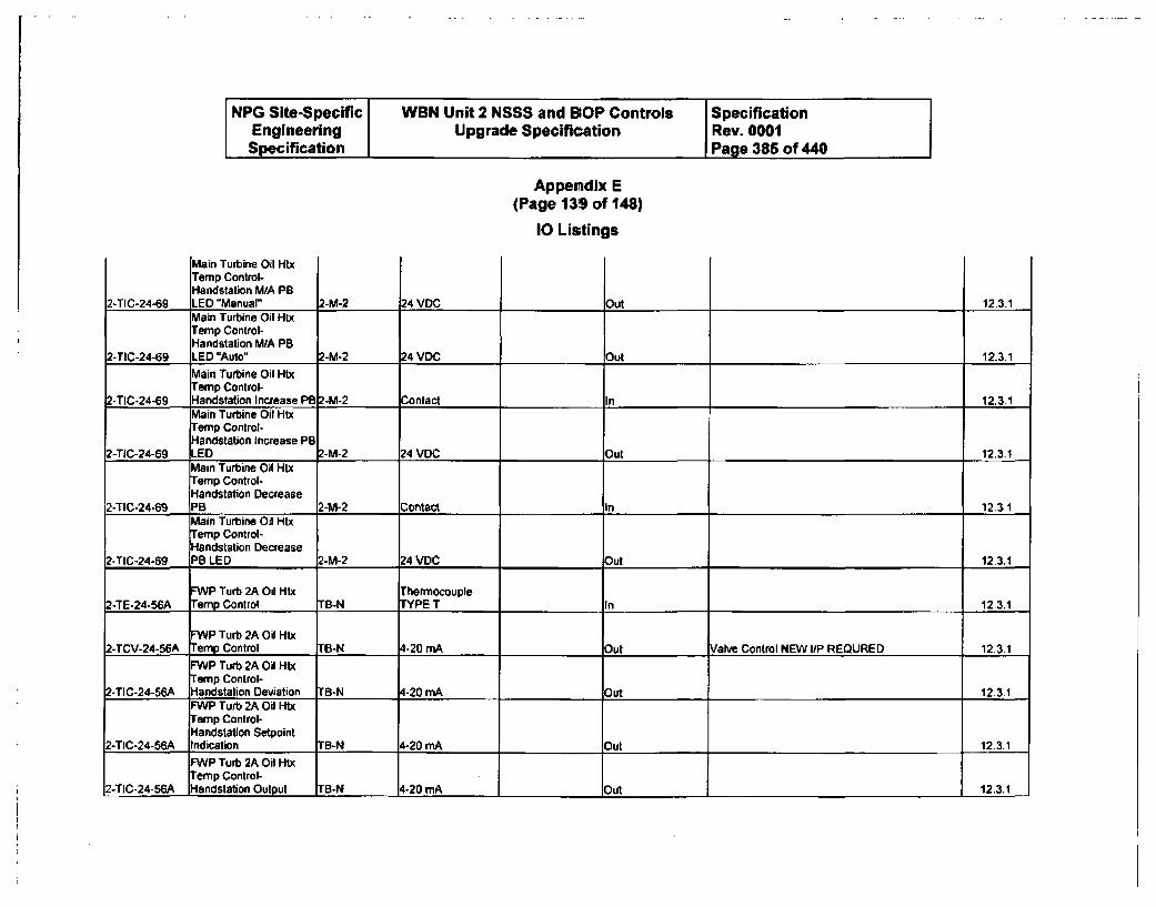
NPG Site-Specific WBN Unit 2 NSSS and SOP Controls SpecificationEngineering Upgrade Specification Rev. 0001Specification Page 385 of 440
Appemdix E(Page 139 of 148)
10 Listings
Main Turbine Oil HtxTemp Control-Ilandstation M/A PBLED "Manuar2-TIC-24-69 2-M-2 24 VOC Out 12.3.1Main Turbine Oil Htx
eemp Control-Handstation MIA PB
2-TIC-24-69 LED "Auto" 2-M-2 24 VDC Out 12-3.1
Main Turbine Oil HIxTemp Control-
2-TIC-24-69 Handstation Increase PB 2-M-2 Contact In 12.3.1Main Turbine Oil HtxTemp Control-Handstation Increase PB
2-TIC-24-69 LED 2-M-2 24 VOC )Out 12.3.1Main Turbine Oil HtxTemp Control-Handstation Decrease
2-TIC-24-69 PB 2-M-2 Contact In 12.3.1Main Turbine Oil HtxTemp Control-Handstation Decrease
2-TIC-24-69 PB LED 2-M-2 24 VDC: Out 12.3.1
FWP Turb 2A Oil Htx Thermocouple2-TE-24-56A Temp Control IB-N TYPE T In 12.3.1
FWP Turb 2A Oil Htx2-TCV-24-56A emp Control TB-N 4-20 mA ._ Out Valve Control NEW I/P REQURED 123.1
FWP Turb 2A Oi HtxTemp Control-
2-TIC-24-56A -landstation Deviation "B-N 4-20 mA Out 12.3.1FWP Turb 2A O0 Htx
remp Control-Handstation Setpoint
2-TIC-24-56A Indication TB-N 4-20 mA ut 12.3.1FWP Turb 2A Oil HtxTemp Control-
2-TIC-24-56A Handstation Output TB-N 4-20 mA Out 12.3.1
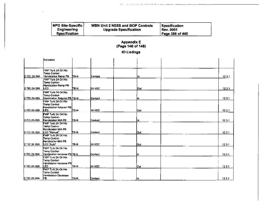
NPG Site-Specific WBN Unit 2 NSSS and BIOP Controls SpecificationEngineering Upgrade Specification Rev. 0001Specification Page 386 of 440
Appendix E(Page 140 of 148)
10 Listings
Indication
FWP Turb 2A Oil HtxTamp Control-
2-TIC-24-56A Handstation Ramp PB TB-N Contact In 12.3.1FWP Turb 2A Oil HtxTemp Control-Handstation Ramp PB
2-TIC-24-56A LED TB-N 24 VDC Out 12.3-1
FWP Turb 2A Oil HtxTamp Control-
2-TIC-24-56A Handstation Setpoint PB TB-N Contact In 12.3.1FWP Turb 2A Oil HtxTamp Control-Handstation Setpoint PB
2-TIC-24-56A LED TB-N 24 VDC _Out 12.3.1
FWP Turb 2A Oil HtxTamp Control-
2-TIC-24-56A Handatation MIA PB TB-N Contact In 12.3.1FWP Turb 2A Oil HtxTamp Control-Handstation M,/A PB
2-TIC-24-56A LED "Manual" TB-N Contact Out 12.3.1FWP Turb 2A Oil HtxTamp Control-Handstation M/A PB
2-TIC-24-56A LED "Auto" TB-N 24 VDC Out 12.3.1
FWP Turb 2A Oil HtxTamp Control-
2-TIC-24-56A Handstation Increase PB TB-N Contact In 12.3.1F--WP Turb 2A Oil HtxTamp Control-Handstation Increase PB
2-TIC-24-56A LED TB-N 24 VDC Out 12-3.1FWP Turb 2A Oil HtbTamp Control-Handstation Decrease
Z-TIC-24-56A PB TB-N Contact In 12-3.1
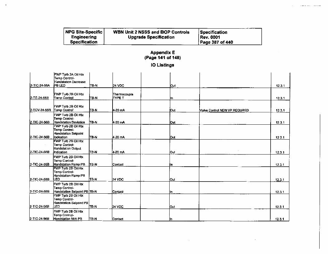
NPG Site-Specific WBN Unit 2 NSSS and 13OP Controls SpecificationEngineering Upgrade Specification Rev. 0001
Specification Page 387 of 440
Appendix E(Page 141 of 148)
10 Listings
FWP Turb 2A Oil HtxTemp Control-Handstation DecreasePB LED2-TIC-24-56A TB-N 24 VOC out 12.3.1
FWP Turb 2B Oil Htx Thermocouple2-TE-24-56B Ternp Control TB-N TYPE T In 12.3.1
FWP Turb 2B Oil Htx2-TCV-24-56B Temp Control TB-N 4-20 mA Out Valve Control NEW I/P REQURED 12.3.1
FWP Turb 2B Oil H-xTemp Control-
2-TIC-24-56B Handstation Deviation TB-N 4-20 mA Out 12-3.1FWPTurb 2B Oil IllTamp Control-Handstation Setpoint
2-TIC-24-56B Indication TB-N 4-20 mA Out 12-3.1FWP Turb 28 Oil HtxTemp Control-Handstatjon Output
2-TIC-24-56B Indication TB-N 4-20 mA Out 12.3.1
FWP Turb 2B Oil HixTemp Control-
2-TIC-24-56B Handstation Ramp PB TB-N Contact In 12.3.1FWP Turb 2B Oil Hl-txTemp Control-Handstation Ramp PB
2-TIC-24-56B LED "B-N 24 VDC Out 12.3.1FWP Turb 2B Oil HtxTemp Control-
2-TIC-24-56B Handslation Setpoint PB TB-N Contact In 12.3.1FWP Turb 2B Oil HtxTemp Control-Handlstation Setpoint PB
2-T1C-24-56B LED TB-N 24 VOC Out 12.3.1MAP Turb 2B Oil HtxTemp Control-
2-TIC-24-56B Handstation M/A PB TB-N Contact In 12.3.1
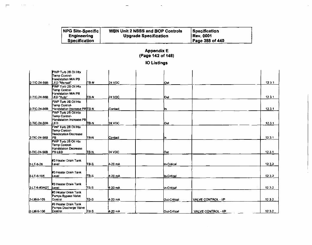
NPG Site-Specific WBN Unit 2 NSSS and BOP Controls SpecificationEngineering Upgrade Specification Rev. 0001Specification Page 388 of 440
Appendix E(Page 142 of 148)
10 Listings
FWP Turb 2B Oil HtxTemp Control--landstation M/A PB
ED 'Manual"2-TIC-24-56B TB-N 24 VDC Out 12.3-1FWP Turb 2B Ol HtxTernp Control-Handstation WA PB
2-TIC-24-56B LED "Auto" TB-N 24 VDC Out 12.3.1FWP Turb 2B Oil HtxTernp Control-
2-TIC-24-56B Handstation Increase PS TB-N Contact In 12.3.1FWP Turb 2B Oil HtxTemp Control-Handstation Increase PB
2-TIC-24-56B LED IB-N 24 VDC Out 12.3.1FWP lurb 2B Oil HtxI-Temp Control-Handstation Decrease
2-TIC-24-56B PB IB-N Contact In 12.3.1FWP Turb 2B Oil HtxTemp Control-Handstation Decrease
2-TIC-24-56B PB LED TB-N 24 VDC Out 12.3.1
#3 Heater Drain Tank2-LT-6-26 Level rB-S 4-20 m.A in-Critical 12.3.2
#3 Heater Drain Tank2-LT-6-106 Level "B-S 4-20 rnA In-Critical 12.3.2
#3 Heater Drain Tank2-LT-6-#3HDT Level rB-S 4-20 mA In-Critical 12.3.2
#3 Heater Drain TankPumps Bypass Valve
2-LM-6-105 Control TB-S 4-20 mA Out-Critical VALVE CONTROL - lIP 12.3.2
#3 Heater Drain TankPumps Discharge Valve
2-LM-6-106 Control rB-S 4-20 mA Out-Critical VALVE CONTROL - I/P 12.3.2
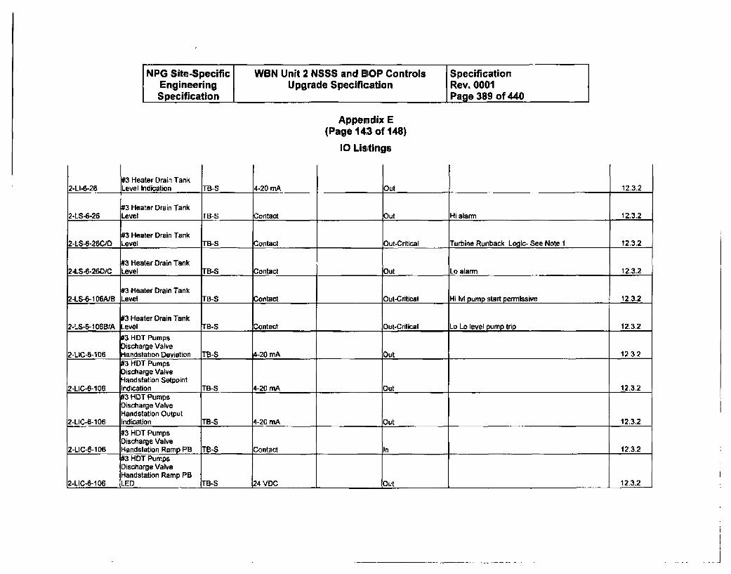
NPG Site-Specific WBN Unit 2 NSSS and BOP Controls SpecificationEngineering Upgrade Specification Rev. 0001Specification Page 389 of 440
Appendix E(Page 143 of 148)
10 Lis;tings
2-LI-4-2693 Heater Drain TankLevel Indication TB-S 4-20 mA Out 12.3.2
#3 Heater Drain Tank2-LS-6-26 Level TB-S Contact Out Hi alarm 12.3.2
#3 Heater Drain Tank2-LS-6-26C0D Level TB-S Contact Out.Cntical Turbine Runback Logic- See Note 1 12.3.2
#3 Neater Drain Tank2-LS-6-26DiC Level TB-S Contact Out Lo alarm 12.3.2
#3 Heater Drain Tank2-LS-6-106A/B Level TB-S Contact Out-Critical Hi IvI pump start permissive 12.3.2
03 Heater Drain Tank2-LS-6-106BA Level TB-S Contact Out-Critical Lo Lo level pump trip 12.3.2
03 HDT PumpsDischarge Valve
2-LIC-6-106 Handstation Deviation TB-S 4-20 mA Out 112.3-2#3 HDT PumpsDischarge ValveHandstation Setpoint
2-LIC-6-106 Indication TB-S 4-20 mA Out 12.3.2#3 HDT PumpsDischarge ValveHandstation Output
2-LIC-6-106 Indication TB-S 4-20 mA Out 12.3.2
#3 HDT PumpsDischarge Valve
2-LIC-6-1006 Handstation Ramp PB. TB-S Contact In 12.3.2#3 HDT PumpsDischarge ValveHandstation Ramp PB
2-LIC-6-106 LED TB-S 24 VDC, Out 12.3.2
.............................................................................i
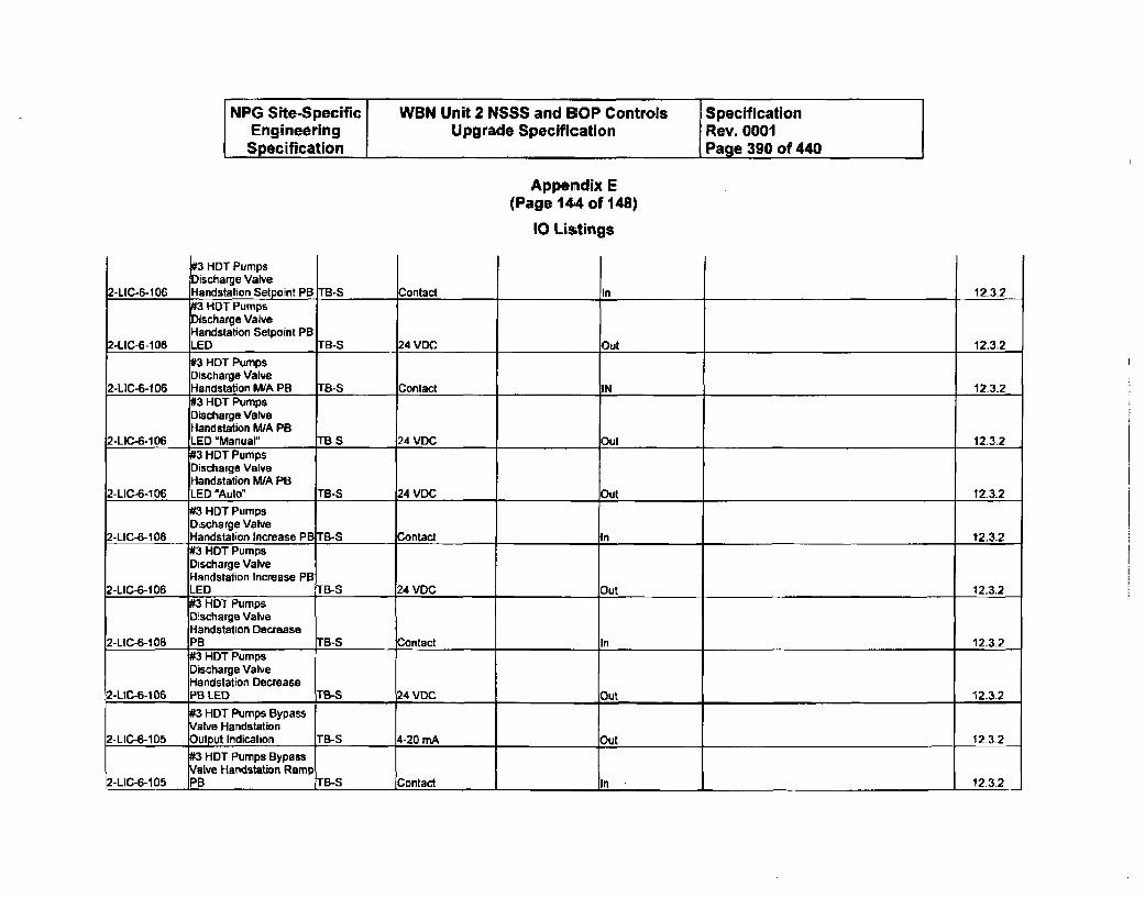
NPG Site-Specific WBN Unit 2 NSSS and BOP Controls SpecificationEngineering Upgrade Specification Rev. 0001Specification Page 390 of 440
Appendix E(Page 144 of 148)
10 Listings
#3 HDT PumpsDischarge ValveHandstation Setooint PB In2-LIC-6-1 06 rB-S Contact 12_3.2#3 HDT PumpsDischarge ValveHandstation Setpoint PB
2-LIC-6-106 LED rB-S 24 VDC Out 12.3.2#3 HDT PumpsDischarge Valve
2-LIC-6-106 Handstation MIA PB r8-s Contact IN 12.3.2#3 HDT PumpsDischarge ValveHandstation MIA PB
2-LIC-6-106 LED "Manuarl TB-S 24 VDC Out 12.3.2#3 HDT PumpsDischarge ValveHandstation M/A PB
2-LIC-6-106 LED "Auto" TB-S 24 VDC Out 12.3.2
#3 HDT PumpsDischarge Valve
2-LIC-6-106 Handstation Increase PB TB-S Contact _ _ 12.3.2#3 HDT Pumps
Discharge ValveHandstation Increase PB
2-LIC-6-106 LED TB-S 24 VDC Out 12.3.2#3 HDT PumpsDischarge Valve
Handstation Decrease2-LIC-6-106 PB TB-S 4ontact Ou 12.3.2
#3 HDT PumpsDischarge ValveHandlstation Decrease
2-LIC-6-106 PB LED TB-S 2)4 VDC Out 12.3.2
#3 HDT Pumps BypassValve Handstation
2-LIC-6-105 _Output Indication TB-S 4-20 mA Out 12-3.2
#3 HDT Pumps Bypass
alve Handstation Ramp2-LIC-6-105 PB TB-S Contact In 12.3.2
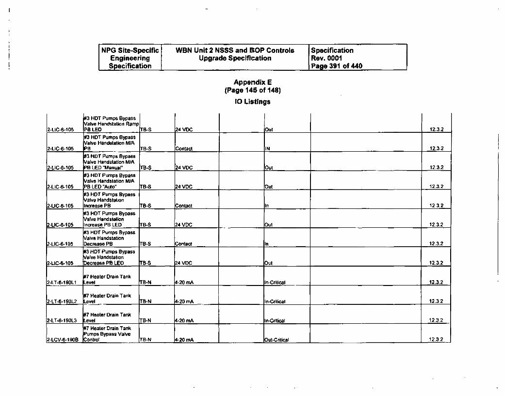
NPG Site-Specific WBN Unit 2 NSSS and BOP Controls SpecificationEngineering Upgrade Specification Rev. 0001Specification Page 391 of 440
Appendix E(Page 145 of 148)
10 Listings
2-LIC-6-105
#3 HDT Pumps BypassValve Handstation RampPB LED TB-S 24 VOC Out 12.3.2
#3 HDT Pumps BypassValve Handstation N/A
2-LIC-6-105 PB TB-S Contact IN 12.3.2
03 HDT Pumps BypassValve Handstation M/A
2-LIC-6-105 PB LED "Manual" TB-S 24 VDC Out 12.3.2
#3 HOT Pumps BypassValve Handstation M/A
2-LIC-6-105 PB LED "Auto" TB-S 24 VDC Out 12.3.2
03 HDT Pumps BypassValve Handstation
2-LIC-6-105 Increase PB T8-S Contact In 12.3.2
#3 HDT Pumps BypassValve Handstation
2-LIC-6-105 Increase PB LED TB-S 24 VDC Out 12.3.2
#3 HDT Pumps BypassValve Handstation
2-LIC-6-105 Decrease PB TB-S Contact In 12-3.2
03 HDT Pumps BypassValve Handstation
2-LIC-6-105 Decrease PB LEO TB-S 24 VDC Out 12.3.2
07 Heater Drain Tank2-LT-6-1901 Level TB-N 4-20 mA In-Critical 12.3.2
#7 Heater Drain Tank2-LT-6-190L2 Level TB-N 4-20 mA In-Critical 12.3.2
#7 Heater Drain Tank2-LT-6-1 9013 Level TB-N 4-20 mA In-Critical 12.3.2
7 Heater Drain TankPumps Bypass Valve
2-LCV-6-190B Control TB-N 4-20 mA Out-Critical 12.3-2
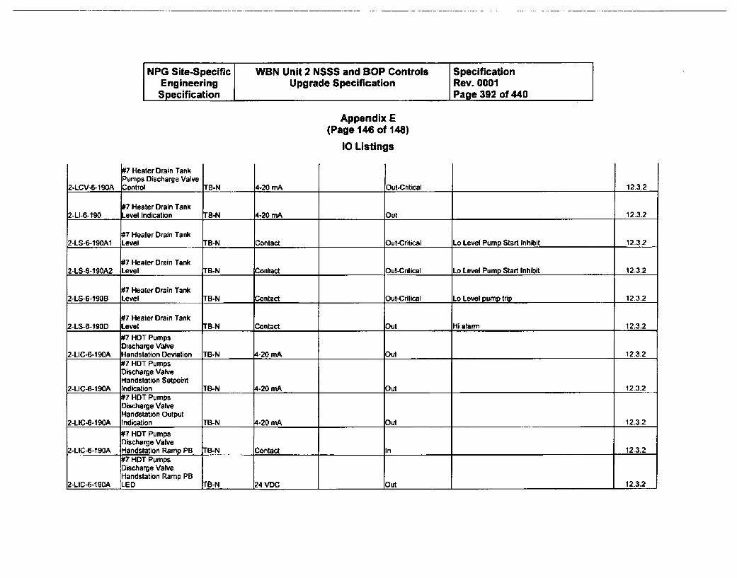
NPG Site-Specific WBN Unit 2 NSSS and BOP Controls SpecificationEngineering Upgrade Specification Rev. 0001Specification Page 392 of 440
Appendix E(Page 146 of 148)
10 Listings
97 Heater Drain TankPumps Discharge ValveControl2-LCV-6-1 90A TB-N 6-20 mA Dut-Critical 12.3.2
#7 Heater Drain Tank2-LI-6-190 Level Indication IB-N 4-20 mA _Out 12.3.2
#7 Heater Drain Tank2-LS-6-190A1 Level TB-N Contact _Out-Critical Lo Level Pump Start Inhibit 12-3.2
#7 Heater Drain Tank2-LS-6-190A2 Level TB-N Contact Out-Critical Lo Level Pump Start Inhibit 12.3.2
#7 Heater Drain Tank2-LS-6-1905 Level TB-N Contact Out-Critical Lo Level pump trip 12.3.2
#7 Heater Drain Tank2-LS-6-190D Level TB-N Contact Out Hi alarm 12.3.2
#7 HDT PumpsDischarge Valve
2-LIC-6-190A Handstation Deviation TB-N 4-20 mA Out 12.3.2#7 HDT PumpsDischarge ValveHandstation Setpoint
2-LIC-6-190A Indication TB-N 4-20 mA Out 12.3.2#7 HDT PumpsDischarge ValveHandstation Output
2-LIC-6-190A Indication TB-N 4-20 mA Out 12.3.2
#7 HDT PumpsDischarge Valve
2-LIC-6-190A Handstation Ramp PB B-N Contact In 12-3.2#7 HDT PumpsDischarge ValveHandstation Ramp PB
2-LIC-6-190A LED TB-N 24 VDC Out 12.3.2
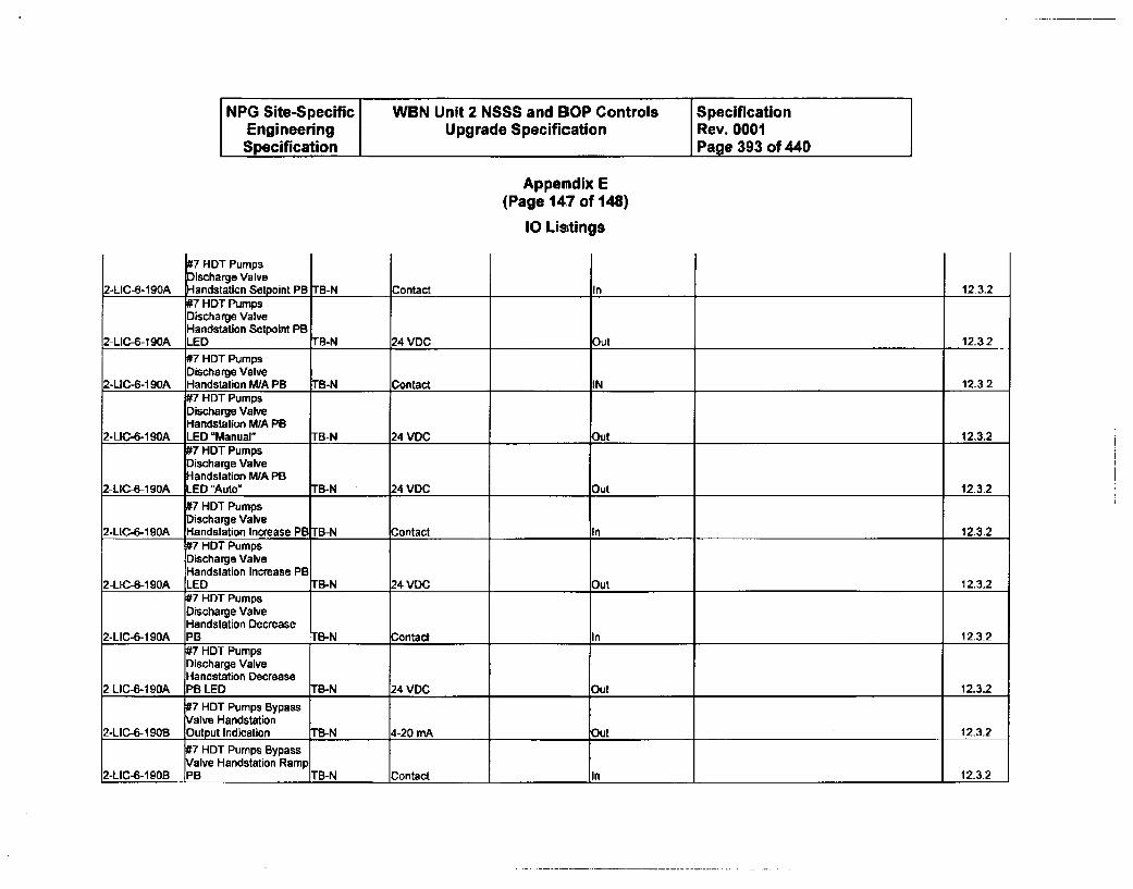
NPG Site-Specific WBN Unit 2 NSSS and BOP Controls SpecificationEngineering Upgrade Specification Rev. 0001Specification Page 393 of 440
Appendix E(Page 147 of 148)
10 Lisitings
2-LIC-6-190A
DishDT PumpsDischarge Valve[Hanidstation Setnaint PB Contact In 123.2#7 HDT PumpsDischarge ValveHandstation Setpoint PB
2-LIC-6-190A LED TB-N 24 VDC Out 12.3.2
#7 HDT PumpsDischarge Valve
2-LIC-6-1 90A Handstation M/A PB TB-N Contact IN 12.3-2#7 HDT PumpsDischarge ValveHandstation WA PB
2-LIC-6-190A LED "Manual" TB-N 24 VDC Out 12.3.2#7 HDT PumpsDischarge ValveHandstation WA PB
2-LIC-6-190A LED "Auto" TB-N 24 VDC Out 12.3.2
#7 HDT PumpsDischarge Valve
2-LIC-6-190A Handstation Increase PB TB-N Contact In 12.3.2#7 HDT PumpsDischarge ValveHandstation Increase PB
2-LIC-6-190A LED TB-N 24 VDC Out 12.3.2#7 HDT PumpsDischarge ValveHandstation Decrease
2-LIC-6-190A PB TB-N Contact In 12.3.2#7 HDT PumpsDischarge ValveHandstation Decrease
2-LIC-6-190A PB LED TB-N 24 VDC Out 12.3.2
#7 HDT Pumps BypassValve Handstation
2-LIC-6-190B Output Indication TB-N 4-20 mA Out 12.3.2#7 HDT Pumps BypassValve Handstation Ramp
2-LIC-6-IQOB PB TB-N Contact In 12.3.2
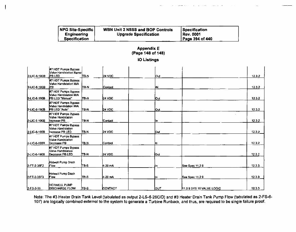
NPG Site-Specific WBN Unit 2 NSSS and BOP Controls SpecificationEngineering Upgrade Specification Rev. 0001Specification Page 394 of 440
Appendix E(Page 14:8 of 148)
10 Listings
Out
17 HDT Pumps Bypassalve Handstation Ramp
P)B LED TB-N2-LIC-6-190B 24 VDC 12.3.2I7 HDT Pumps Bypassalve Handstation W/A
2-LIC-6-190B PB TB-N Contact IN 12.3.2•7 HOT Pumps Bypass
alve Handstation M/A2-LIC-6-190B PB LED "Manual" TB-N 24 VDC Out 12.3.2
7 HDT Pumps Bypassalve Handstation MIA
2-LIC-6-190B B LED "Auto" TB-N 24 VDC Out 12.3.2
#7 HDT Pumps BypassValve Handstation
2-LIC-6-190B Increase PB TB-N Contact In 12.3.2
#7 HDT Pumps BypassValve Handstation
2-LIC-6-190B Increase PB LED TB-N 24 VDC Out 12.3.2#7 HDT Pumps BypassValve Handstation
Z-LIC-6-190B Decrease PB TB-N Contact In 12.3.2
#7 HDT Pumps BypassValve Handstation
2-LIC-6-1 9GB Decrease PB LED TB-N 24 VDC Out 12.3.2
Hotwell Pump Disch2-FT-2-35F2 Flow TB-S 4-20 mA In See Spec 11.2.9 12.3.3
Hotwell Pump Disch2-FT-2-35F3 Flow TB-S -20 mA In See Spec 11.2.9 12.3.3
HO1WELL PUMP2-FS-2-35 DISCHARGE FLOW TB-S •ONTACT OUT 11.2.9 SYS 15 VALVE LOGIC 12.3.3
Note: The #3 Heater Drain Tank Level (tabulated as output 2-LS-6-26C/D) and #3 Heater Drain Tank Pump Flow (tabulated as 2-FS-6-107) are logically combined external to the system to generate a Turbine Runback, and thus, are required to be single failure proof.
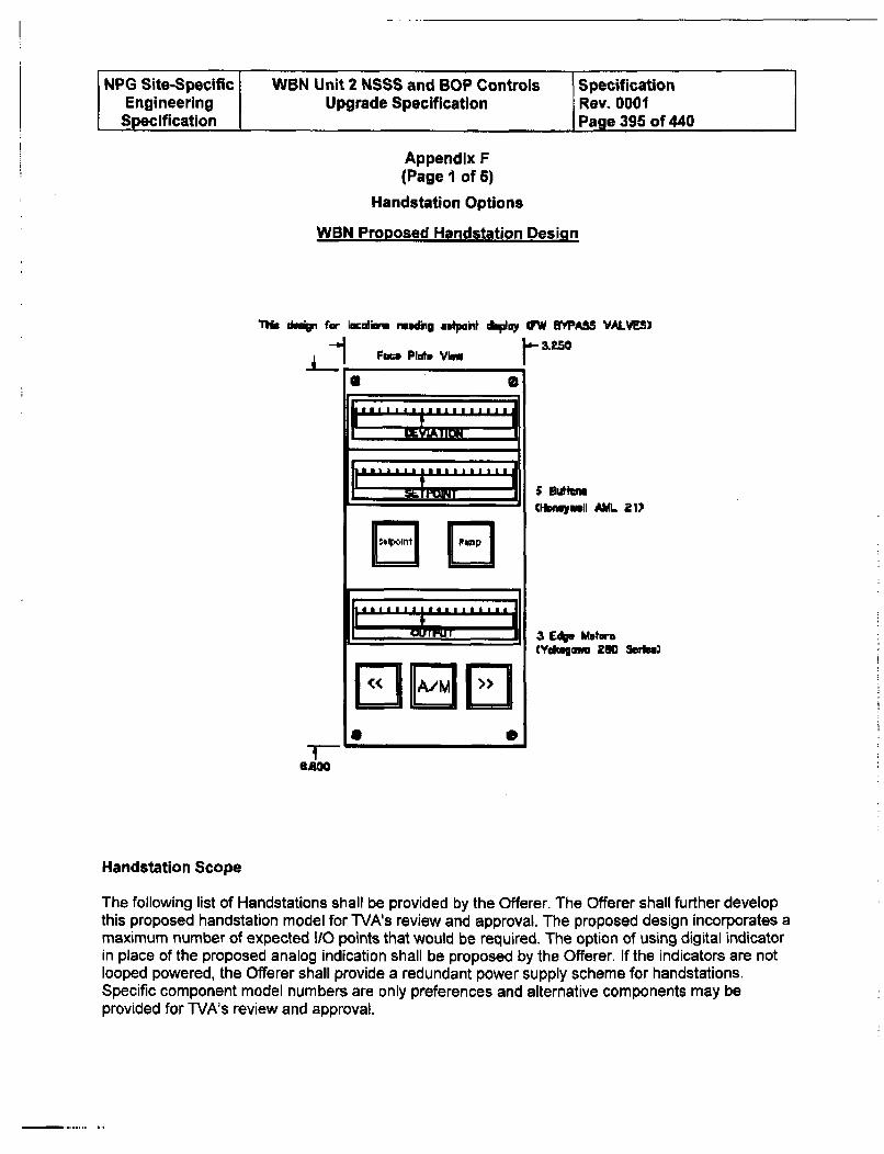
NPG Site-Specific WBN Unit 2 NSSS and BOP Controls SpecificationEngineering Upgrade Specification Rev. 0001Specification Page 395 of 440
Appendix F(Page I of 6)
Handstation Options
WBN Proposed Handstation Design
Ilia ckm~ far L6caflm r..dmg astpaht d~.y OW "YASS VALVE)
F•m Plot* View
I 9LVIAIIIUMMI
Cfrawyll ML 21)
I , Vur~uT 3 Edge Motor'
S S
6.600
Handstation Scope
The following list of Handstations shall be provided by the Offerer. The Offerer shall further developthis proposed handstation model for TVA's review and approval. The proposed design incorporates amaximum number of expected I/0 points that would be required. The option of using digital indicatorin place of the proposed analog indication shall be proposed by the Offerer. If the indicators are notlooped powered, the Offerer shall provide a redundant power supply scheme for handstations.Specific component model numbers are only preferences and alternative components may beprovided for TVA's review and approval.
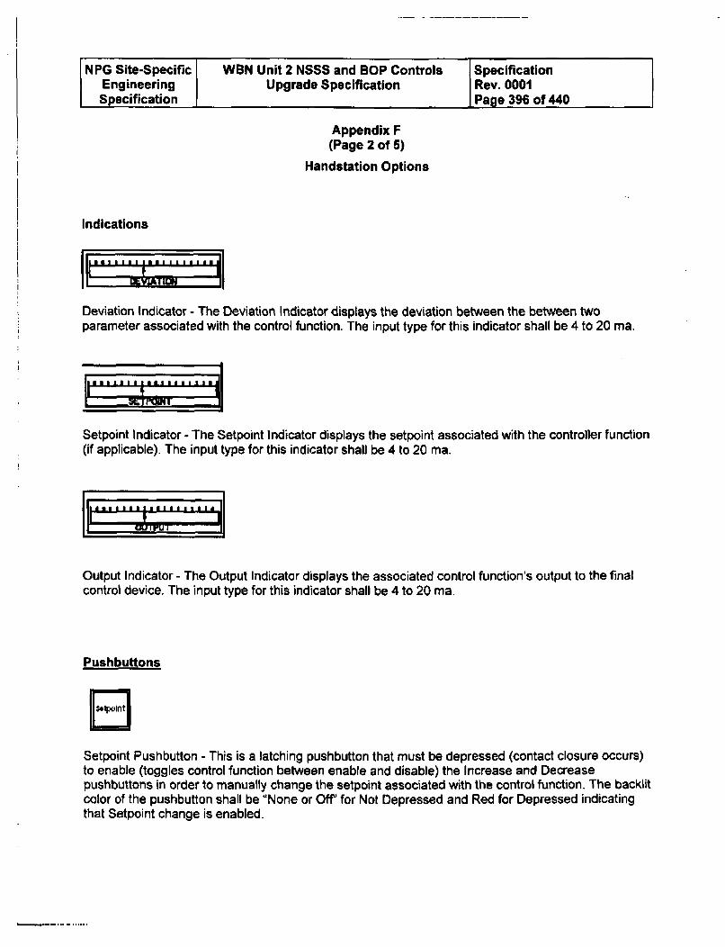
NPG Site-Specific WBN Unit 2 NSSS and BOP Controls SpecificationEngineering Upgrade Specification Rev. 0001Specification Page 396 of 440
Appendix F(Page 2 of 5)
Handstation Options
Indications
Deviation Indicator - The Deviation Indicator displays the deviation between the between twoparameter associated with the control function. The input type for this indicator shall be 4 to 20 ma.
lnll.a I p I I Bil i i i i i i iI l
Setpoint Indicator - The Setpoint Indicator displays the setpoint associated with the controller function(if applicable). The input type for this indicator shall be 4 to 20 ma.
F''.. I I jOutput Indicator - The Output Indicator displays the associated control function's output to the finalcontrol device. The input type for this indicator shall be 4 to 20 ma.
Pushbuttons
Setpoint Pushbutton - This is a latching pushbutton that must be depressed (contact closure occurs)to enable (toggles control function between enable and disable) the Increase and Decreasepushbuttons in order to manually change the setpoint associated with the control function. The backlitcolor of the pushbutton shall be "None or Off" for Not Depressed and Red for Depressed indicatingthat Setpoint change is enabled.
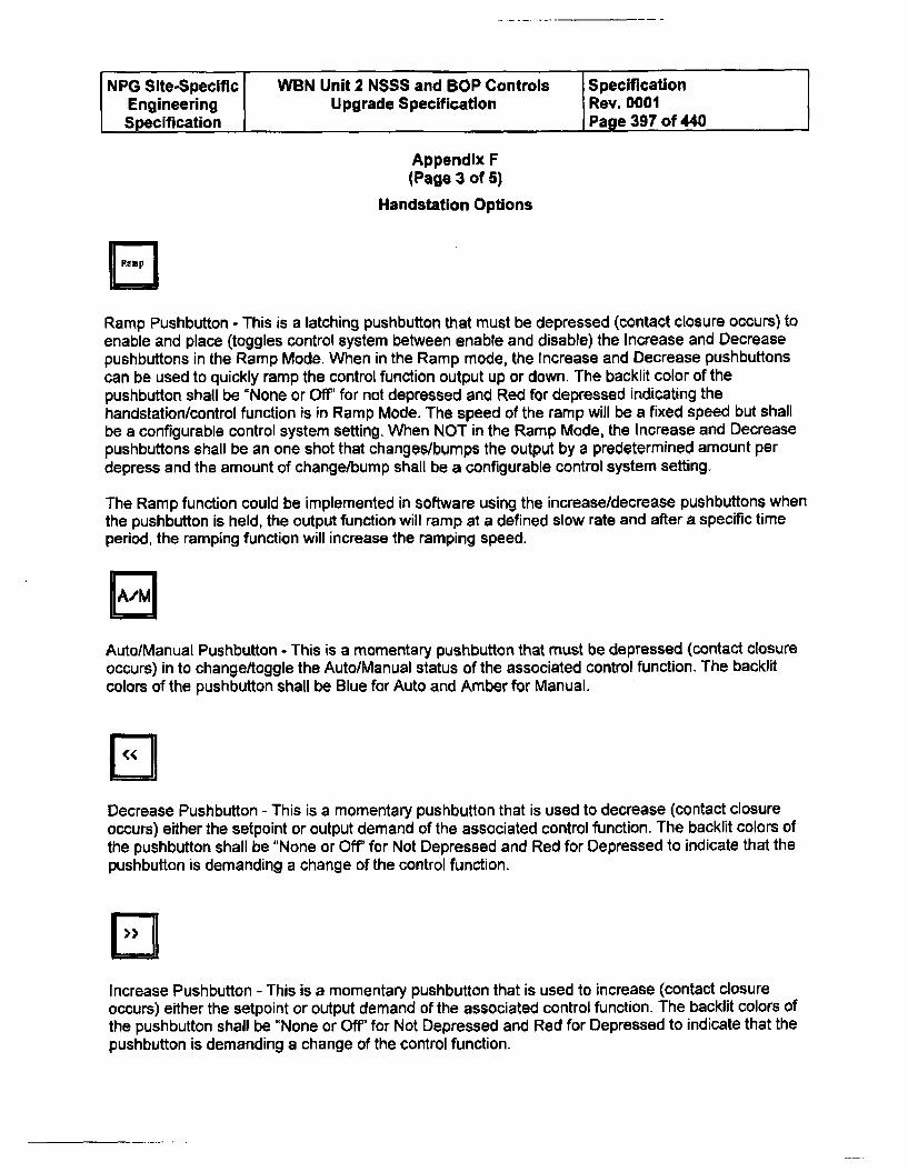
NPG Site-Specific WBN Unit 2 NSSS and BOP Controls SpecificationEngineering Upgrade Specification Rev. 0001Specification Page 397 of 440
Appendix F(Page 3 of 5)
Handstation Options
Ramp Pushbutton - This is a latching pushbutton that must be depressed (contact closure occurs) toenable and place (toggles control system between enable and disable) the Increase and Decreasepushbuttons in the Ramp Mode. When in the Ramp mode, the Increase and Decrease pushbuttonscan be used to quickly ramp the control function output up or down. The backlit color of thepushbutton shall be "None or Off" for not depressed and Red for depressed indicating thehandstation/control function is in Ramp Mode. The speed of the ramp will be a fixed speed but shallbe a configurable control system setting. When NOT in the Ramp Mode, the Increase and Decreasepushbuttons shall be an one shot that changes/bumps the output by a predetermined amount perdepress and the amount of change/bump shall be a configurable control system setting.
The Ramp function could be implemented in software using the increase/decrease pushbuttons whenthe pushbutton is held, the output function will ramp at a defined slow rate and after a specific timeperiod, the ramping function will increase the ramping speed.
Auto/Manual Pushbutton - This is a momentary pushbutton that must be depressed (contact closureoccurs) in to change/toggle the Auto/Manual status of the associated control function. The backlitcolors of the pushbutton shall be Blue for Auto and Amber for Manual.
Decrease Pushbutton - This is a momentary pushbutton that is used to decrease (contact closureoccurs) either the setpoint or output demand of the associated control function. The backlit colors ofthe pushbutton shall be "None or Off" for Not Depressed and Red for Depressed to indicate that thepushbutton is demanding a change of the control function.
Increase Pushbutton - This is a momentary pushbutton that is used to increase (contact closureoccurs) either the setpoint or output demand of the associated control function. The backlit colors ofthe pushbutton shall be "None or Off' for Not Depressed and Red for Depressed to indicate that thepushbutton is demanding a change of the control function.
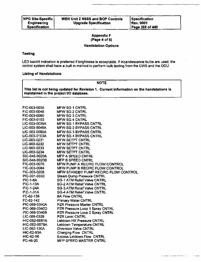
NPG Site-Specific WON Unit 2 NSSS and BOP Controls SpecificationEngineering Upgrade Specification Rev. 0001Specification Page 398 of 440
Appendix F(Page 4 of 5)
Handstation Options
Testing
LED backlit indication is preferred if brightness is acceptable. If incandescence bulbs are used, thecontrol system shall have a built in method to perform bulb testing from the EWS and the ODU.
Listing of Handstations
NOTE
This list is not being updated for Revision 1. Current information on the handstations ismaintained in the project 110 database.
FIC-003-0035FIC-003-0048FIC-003-0090FIC-003-0103LIC-003-0035ALIC-003-0048ALIC-003-0090ALIC-003-0103ALIC-003-0231LIC-003-0232LIC-003-0233LIC-003-0234SIC-046-0020ASIC-046-0020BFIC-003-0070FIC-003-0084FIC-003-0208PIC-001-0033PIC-1-6APIC-1-13APIC-1-24APIC-1-31AFC-62-139FC-62-142PIC-068-0340APIC-068-0340DPIC-068-0340BLIC-068-0339HIC-062-0081AHIC-062-0078ALIC-062-130AHIC-62-93AHIC-62-56PC-46-20
MFW SG 1 CNTRLMFW SG 2 CNTRLMFW SG 3 CNTRLMFW SG 4 CNTRLMFW SG 1 BYPASS CNTRLMFW SG 2 BYPASS CNTRLMFW SG 3 BYPASS CNTRLMFW SG 4 BYPASS CNTRLMFW SETPT CNTRLMFW SETPT CNTRLMFW SETPT CNTRLMFW SETPT CNTRLMFP A SPEED CNTRLMFP B SPEED CNTRLMFW PUMP A RECIRC FLOW CONTROLMFW PUMP B RECIRC FLOW CONTROLMFW STANDBY PUMP RECIRC FLOW CONTROLSteam Dump Pressure CNTRLSG-1 ATM Relief Valve CNTRLSG-2 ATM Relief Valve CNTRLSG-3 ATM Relief Valve CNTRLSG-4 ATM Relief Valve CNTRLBA Flow CNTRLPrimary Water CNTRLPZR Pressure Master CNTRLPZR Pressure Loop 1 Spray CNTRLPZR Pressure Loop 2 Spray CNTRLPZR Level CNTRLLetdown HX Pressure CNTRLLetdown Temperature CNTRLDiversion Valve CNTRLCharging Flow CNTRLExcess Letdown Flow CNTRLMFP SPEED MASTER CNTRL
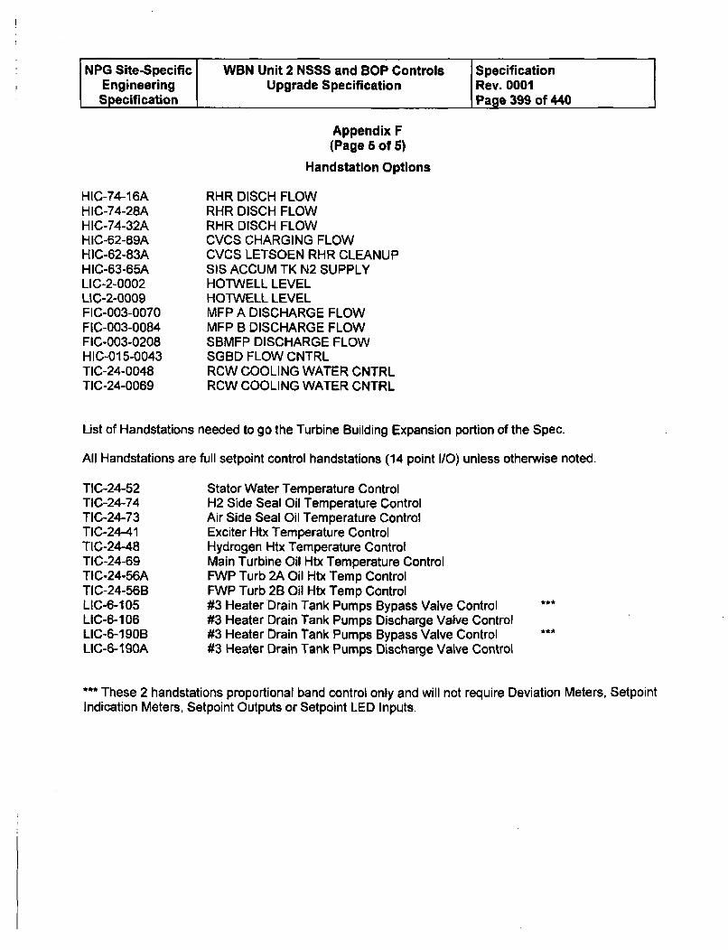
NPG Site-Specific WBN Unit 2 NSSS and BOP Controls SpecificationEngineering Upgrade Specification Rev. 0001Specification Page 399 of 440
Appendix F(Page 6 of 6)
Handstatlon Options
HIC-74-16AHIC-74-28AHIC-74-32AHIC-62-89AHIC-62-83AHIC-63-65ALIC-2-0002LIC-2-0009FIC-003-0070FIC-003-0084FIC-003-0208HIC-015-0043TIC-24-0048TIC-24-0069
RHR DISCH FLOWRHR DISCH FLOWRHR DISCH FLOWCVCS CHARGING FLOWCVCS LETSOEN RHR CLEANUPSIS ACCUM TK N2 SUPPLYHOTWELL LEVELHOTWELL LEVELMFP A DISCHARGE FLOWMFP B DISCHARGE FLOWSBMFP DISCHARGE FLOWSGBD FLOW CNTRLRCW COOLING WATER CNTRLRCW COOLING WATER CNTRL
List of Handstations needed to go the Turbine Building Expansion portion of the Spec.
All Handstations are full setpoint control handstations (14 point I/O) unless otherwise noted.
TIC-24-52TIC-24-74TIC-24-73TIC-24-41TIC-24-48TIC-24-69TIC-24-56ATIC-24-56BLIC-6-105LIC-6-106LIC-6-190BLIC-6-190A
Stator Water Temperature ControlH2 Side Seal Oil Temperature ControlAir Side Seal Oil Temperature ControlExciter Htx Temperature ControlHydrogen Htx Temperature ControlMain Turbine Oil Htx Temperature ControlFWP Turb 2A Oil Htx Temp ControlFWP Turb 2B Oil Htx Temp Control#3 Heater Drain Tank Pumps Bypass Valve Control#3 Heater Drain Tank Pumps Discharge Valve Control#3 Heater Drain Tank Pumps Bypass Valve Control#3 Heater Drain Tank Pumps Discharge Valve Control
*** These 2 handstations proportional band control only and will not require Deviation Meters, SetpointIndication Meters, Setpoint Outputs or Setpoint LED Inputs.
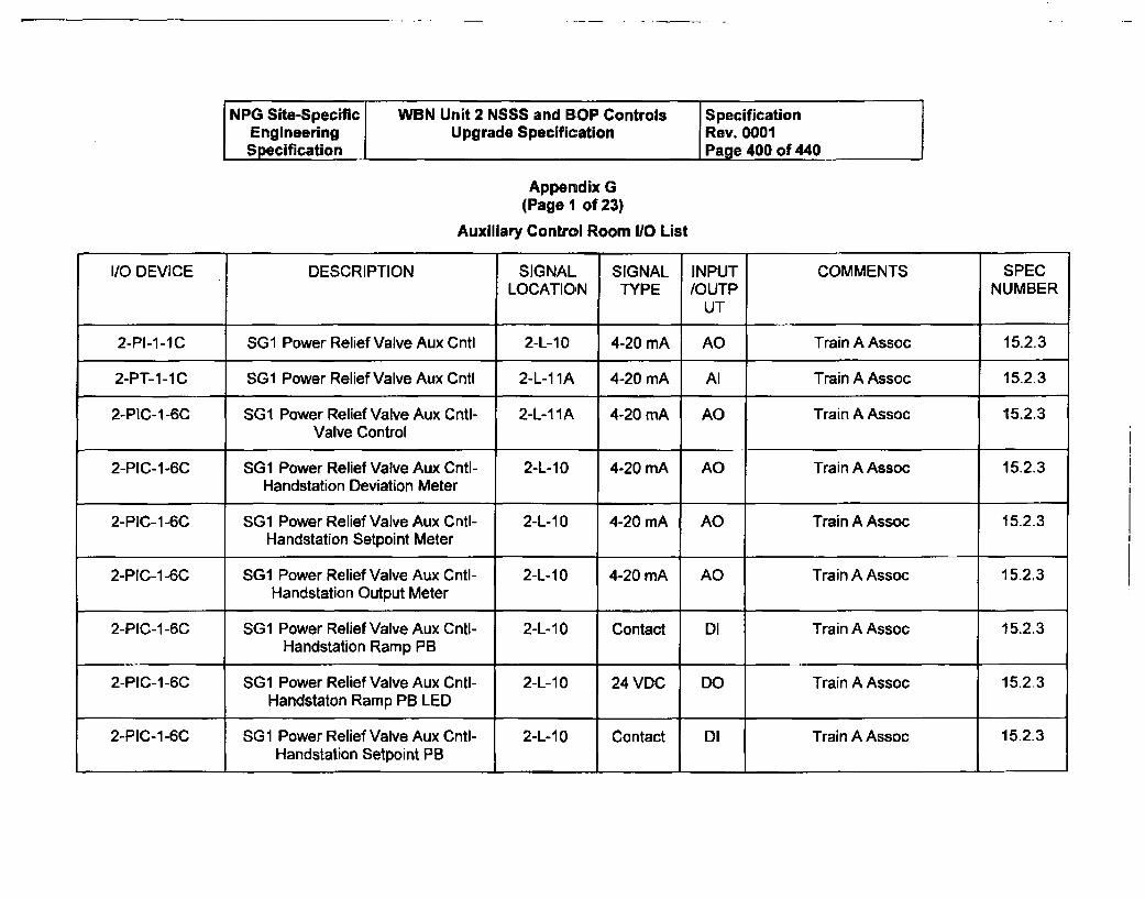
NPG Site-Specific WBN Unit 2 NSSS and BOP Controls SpecificationEngineering Upgrade Specification Rev. 0001Specification Page 400 of 440
Appendix G(Page 1 of 23)
Auxiliary Control Room 1/0 List
I/O DEVICE DESCRIPTION SIGNAL SIGNAL INPUT COMMENTS SPECLOCATION TYPE /OUTP NUMBER
UT
2-PI-1-IC SG 1 Power Relief Valve Aux Cntl 2-L-10 4-20 mA AO Train A Assoc 15.2.3
2-PT-i-iC SG1 Power Relief Valve Aux Cntl 2-L-1i1A 4-20 mA Al Train A Assoc 15.2.3
2-PIC-1-6C SGl Power Relief Valve Aux Cntl- 2-L-11A 4-20 mA AO Train A Assoc 15.2.3Valve Control
2-PIC-1-6C SG1 Power Relief Valve Aux Cntl- 2-L-10 4-20 mA AO Train A Assoc 15.2.3Handstation Deviation Meter
2-PIC-1-6C SGI Power Relief Valve Aux Cntl- 2-L-10 4-20 mA AO Train A Assoc 15.2.3Handstation Setpoint Meter
2-PIC-1 -6C SG1 Power Relief Valve Aux Cntl- 2-L-10 4-20 mA AO Train A Assoc 15.2.3Handstation Output Meter
2-PIC-1-6C SG1 Power Relief Valve Aux Cntl- 2-L-10 Contact DI Train A Assoc 15.2.3Handstation Ramp PB
2-PIC-1-6C SG1 Power Relief Valve Aux Cntl- 2-L-10 24 VDC DO Train A Assoc 15.2.3Handstaton Ramp PB LED
2-PIC-1-6C SG1 Power Relief Valve Aux Cntl- 2-L-10 Contact DI Train A Assoc 15.2.3Handstation Setpoint PB
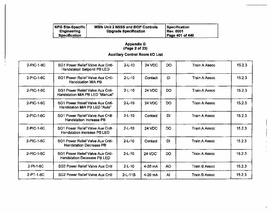
NPG Site-Specific WBN Unit 2 NSSS and BIOP Controls SpecificationEngineering Upgrade Specification Rev. 0001Specification Page 401 of 440
Appendix G
(Page 2 of 23)
Auxiliary Control Room 110 List
2-PIC-1-6C SG1 Power Relief Valve Aux Cntl- 2-L-10 24 VDC DO Train A Assoc 15.2.3Handstation Setpoint PB LED
2-PIC-1-6C SG1 Power Relief Valve Aux Cntl- 2-L-10 Contact DI Train A Assoc 15.2.3Handstation M/A PB
2-PIC-1-6C SG1 Power Relief Valve Aux Cntl- 2-L-1 0 24 VDC DO Train A Assoc 15.2.3Handstation M/A PB LED "Manual"
2-PIC-1-6C SGi Power Relief Valve Aux Gntl- 2-L-10 24 VDC DO Train A Assoc 15.2.3Handstation M/A PB LED "Auto"
2-PIC-1 -6C SG1 Power Relief Valve Aux Cntl- 2-L-10 Contact DI Train A Assoc 15.2.3Handstation Increase PB
2-PIC-1-6C SG1 Power Relief Valve Aux CnU- 2-L-10 24 VDC DO Train A Assoc 15.2.3Handstation Increase PB LED
2-PIC-1-6C SG1 Power Relief Valve Aux Cntl- 2-L-10 Contact DI Train A Assoc 15.2.3Handstation Decrease PB
2-PIC-1-6C SG1 Power Relief Valve Aux Cntl- 2-L-10 24 VDC' DO Train A Assoc 15.2.3
Handstation Decrease PB LED
2-PI-1 -8C SG2 Power Relief Valve Aux Cntl 2-L-10 4-20 mA AO Train B Assoc 15.2.3
2-PT-1 -8C SG2 Power Relief Valve Aux Cntl 2-L-1i1B 4-20 mA Al Train B Assoc 15.2.3
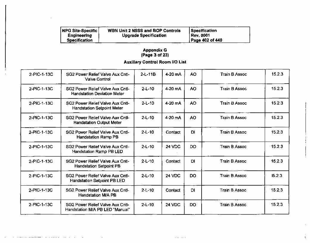
NPG Site-Specific WBN Unit 2 NSSS and BIOP Controls SpecificationEngineering Upgrade Specification Rev. 0001Specification Page 402 of 440
Appendix G(Page 3 of 23)
Auxiliary Control Room 110 List
2-PIC-1-13C SG2 Power Relief Valve Aux Cntl- 2-L-111B; 4-20 mA AO Train B Assoc 15.2.3Valve Control
2-PIC-1-13C SG2 Power Relief Valve Aux Cntl- 2-L-10 4-20 mA AO Train B Assoc 15.2.3Handstation Deviation Meter
2-PIC-1-13C SG2 Power Relief Valve Aux Cntl- 2-L-10 4-20 mA AO Train B Assoc 15.2.3Handstation Setpoint Meter
2-PIC-1-13C SG2 Power Relief Valve Aux Cntl- 2-L-10 4-20 mA AO Train B Assoc 15.2.3Handstation Output Meter
2-PIC-1 -1 3C SG2 Power Relief Valve Aux Cntl- 2-L-10 Contact DI Train B Assoc 15.2.3Handstation Ramp PB
2-PIC-1-13C SG2 Power Relief Valve Aux Cntl- 2-L-10 24 VDC DO Train B Assoc 15.2.3Handstation Ramp PB LED
2-PIC-1-13C SG2 Power Relief Valve Aux Cntl- 2-L-10 Contact Dl Train B Assoc 15.2.3Handstation Setpoint PB
2-PIC-1-13C SG2 Power Relief Valve Aux Cnti- 2-L-10 24 VDC DO Train B Assoc 15.2.3Handstation Setpoint PB LED
2-PIC-1-13C SG2 Power Relief Valve Aux CntI- 2-L-10 Contact DI Train B Assoc 15.2.3Handstation M/A PB
2-PIC-1-13C SG2 Power Relief Valve Aux Cntl- 2-L-1 0 24 VDC DO Train B Assoc 15.2.3Handstation M/A PB LED "Manual"
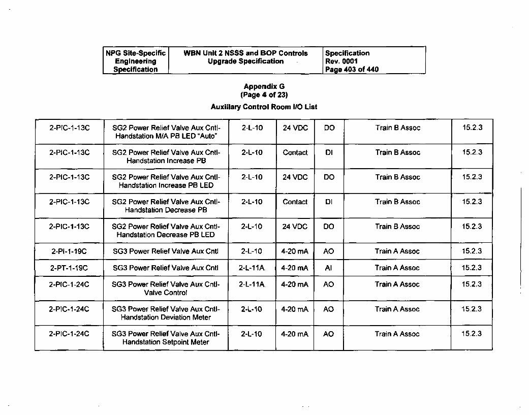
NPG Site-Specific WBN Unit 2 NSSS and BOP Controls SpecificationEngineering Upgrade Specification Rev. 0001Specification Page 403 of 440
Appendix G
(Page 4 of 23)
Auxiliary Control Room 110 List
2-PIC-1-13C SG2 Power Relief Valve Aux Cntl- 2-L-10 24 VDC DO Train B Assoc 15.2.3Handstation M/A PB LED "Auto"
2-PIC-1-13C SG2 Power Relief Valve Aux Cntl- 2-L-10 Contact Dl Train B Assoc 15.23Handstation Increase PB
2-PIC-1-13C SG2 Power Relief Valve Aux Cntl- 2-L-10 24 VDC DO Train B Assoc 15.2.3Handstation Increase PB LED
2-PIC-1-13C SG2 Power Relief Valve Aux Cntl- 2-L-10 Contact DI Train B Assoc 15.2.3Handstation Decrease PB
2-PIC-1-13C SG2 Power Relief Valve Aux Cntl- 2-L-1 0 24 VDC DO Train B Assoc 15.2.3
Handstation Decrease PB LED
2-PI-1-19C SG3 Power Relief Valve Aux Cntl 2-L-10 4-20 mA AO Train A Assoc 15.2.3
2-PT-1-19C SG3 Power Relief Valve Aux Cntl 2-L-1 IA. 4-20 mA Al Train A Assoc 15.2.3
2-PIC-1-24C SG3 Power Relief Valve Aux Cntl- 2-L-11A. 4-20 mA AO Train A Assoc 15.2.3Valve Control
2-PlC-1-24C SG3 Power Relief Valve Aux Cntl- 2-L-10 4-20 mA AO Train A Assoc 15.2.3Handstation Deviation Meter
2-PIC-1 -24C SG3 Power Relief Valve Aux Cntl- 2-L-10 4-20 mA AO Train A Assoc 15.2.3Handstation Setpoint Meter
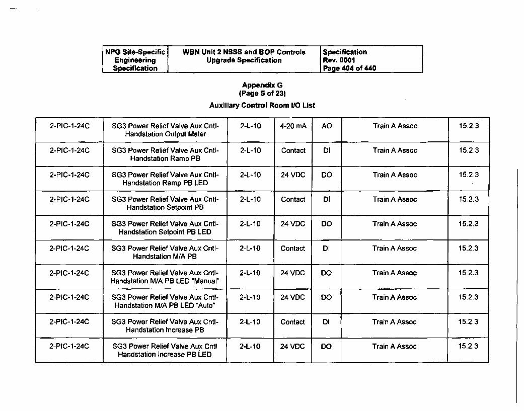
NPG Site-Specific WBN Unit 2 NSSS and BOP Controls SpecificationEngineering Upgrade Specification Rev. 0001Specification Page 404 of 440
Appenidix G
(Page 5 of 23)
Auxiliary Control Room 1/O List
2-PIC-1-24C SG3 Power Relief Valve Aux Cntl- 2-L-10 4-20 mA AO Train A Assoc 15.2.3Handstation Output Meter
2-PIC-1-24C SG3 Power Relief Valve Aux Cntl- 2-L-10 Contact DI Train A Assoc 15.2.3Handstation Ramp PB
2-PIC-1-24C SG3 Power Relief Valve Aux Cntl- 2-L-10 24 VDC DO Train A Assoc 15.2.3Handstation Ramp PB LED
2-PIC-1-24C SG3 Power Relief Valve Aux Cntl- 2-L-10 Contact DI Train A Assoc 15.2.3Handstation Setpoint PB
2-PIC-1-24C SG3 Power Relief Valve Aux Cntl- 2-L-10 24 VDC DO Train A Assoc 15.2.3Handstation Setpoint PB LED
2-PIC-1-24C SG3 Power Relief Valve Aux Cntl- 2-L-10 Contact DI Train A Assoc 15.2.3Handstation M/A PB
2-PIC-1-24C SG3 Power Relief Valve Aux Cntl- 2-L-10 24 VDC DO Train A Assoc 15.2.3H-andstation M/A PB LED 'Manual"
2-PIC-1 -24C SG3 Power Relief Valve Aux Cntl- 2-L-10 24 VDC DO Train A Assoc 15.2.3Handstation INA PB LED "Auto"
2-PIC-1-24C SG3 Power Relief Valve Aux Cntl- 2-L-10 Contact DI Train A Assoc 15.2.3Handstation Increase PB
2-PIC-1-24C SG3 Power Relief Valve Aux Cntl 2-L-10 24 VDC DO Train A Assoc 15.2.3Handstation Increase PB LED
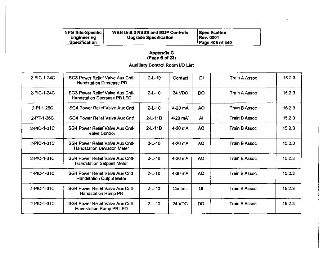
NPG Site-Specific WBN Unit 2 NSSS and BOP Controls SpecificationEngineering Upgrade Specification Rev. 0001Specification Page 405 of 440
Appendix G
(Page 6 of 23)
Auxiliary Control Room 110 List
2-PIC-1-24C SG3 Power Relief Valve Aux CntI- 2-L-10 Contact D1 Train A Assoc 15.2.3Handstation Decrease PB
2-PIC-1-24C SG3 Power Relief Valve Aux Cntl- 2-L-10 24 VDC DO Train A Assoc 15.2.3
Handstation Decrease PB LED
2-PI-1-26C SG4 Power Relief Valve Aux Cntl 2-L-10 4-20 mA AO Train B Assoc 15.2.3
2-PT-1 -26C SG4 Power Relief Valve Aux Cntl 2-L-1 1BR 4-20 mA" Al Train B Assoc 15.2.3
2-PIC-1-31C SG4 Power Relief Valve Aux Cntl- 2-L-1 I B 4-20 mA AO Train B Assoc 15.2.3Valve Control
2-PIC-1-31C SG4 Power Relief Valve Aux Cntl- 2-L-10 4-20 mA AO Train B Assoc 15.2.3Handstation Deviation Meter
2-PIC-1-31C SG4 Power Relief Valve Aux Cntl- 2-L-10 4-20 mA AO Train B Assoc 15.2.3Handstation Setpoint Meter
2-PIC-1-31C SG4 Power Relief Valve Aux Cntl- 2-L-10 4-20 mA AO Train B Assoc 15.2.3Handstation Output Meter
2-PIC-1-31C SG4 Power Relief Valve Aux CntI- 2-L-10 Contact DI Train B Assoc 15.2.3Handstation Ramp PB
2-PIC-1-31C SG4 Power Relief Valve Aux Cnti- 2-L-1 0 24 VDC DO Train B Assoc 15.2.3Handstation Ramp PB LED
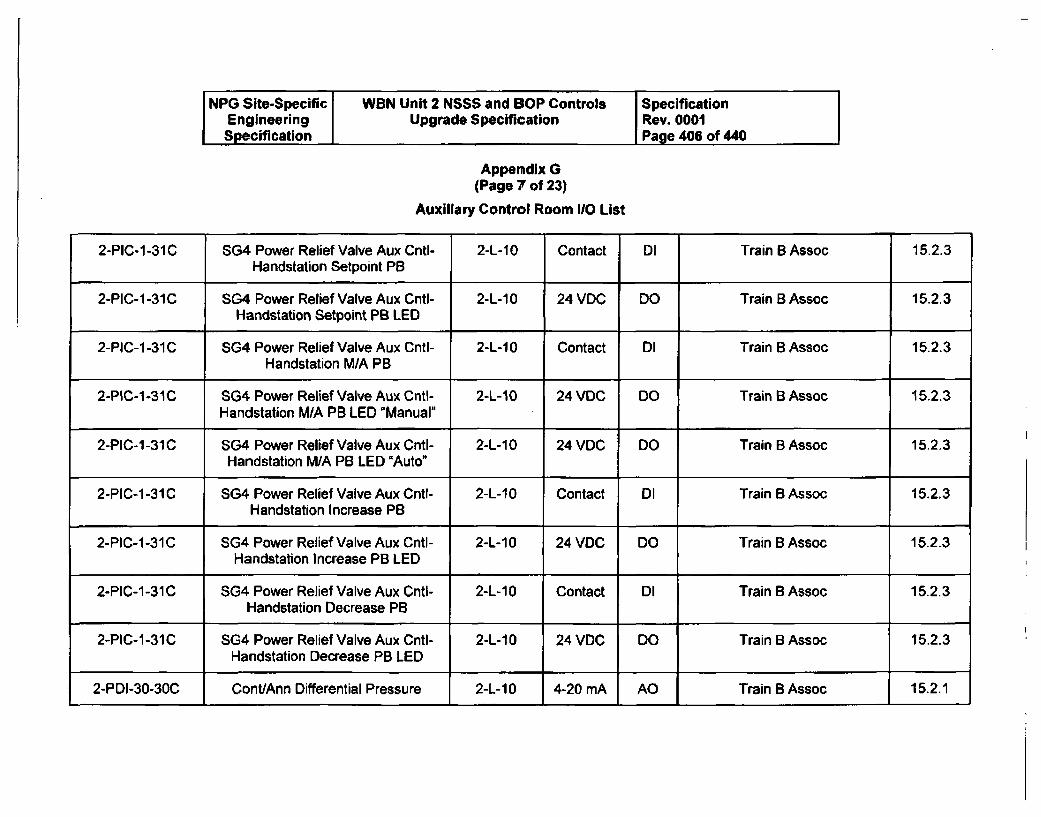
NPG Site-Specific WBN Unit 2 NSSS and BOP Controls SpecificationEngineering Upgrade Specification Rev. 0001Specification Page 406 of 440
Appendix G
(Page 7 of 23)
Auxiliary Control Room 110 List
2-PIC-1-31C SG4 Power Relief Valve Aux Cntl- 2-L-10 Contact DI Train B Assoc 15.2.3Handstation Setpoint PB
2-PIC-1-31C SG4 Power Relief Valve Aux Cntl- 2-L-10 24 VDC DO Train B Assoc 15.2.3Handstation Setpoint PB LED
2-PIC-1-31C SG4 Power Relief Valve Aux Cntl- 2-L-10 Contact DI Train B Assoc 15.2.3Handstation M/A PB
2-PIC-1-31C SG4 Power Relief Valve Aux Cntl- 2-L-10 24 VDC DO Train B Assoc 15.2.3Handstation M/A PB LED "Manual"
2-PIC-1-31C SG4 Power Relief Valve Aux Cntl- 2-L-10 24 VDC DO Train B Assoc 15.2.3Handstation M/A PB LED "Auto"
2-PIC-1-31C SG4 Power Relief Valve Aux Cntl- 2-L-10 Contact DI Train B Assoc 15.2.3Handstation Increase PB
2-PIC-1-31C SG4 Power Relief Valve Aux Cntl- 2-L-10 24 VDC DO Train B Assoc 15.2.3Handstation Increase PB LED
2-PIC-1-31C SG4 Power Relief Valve Aux Cntl- 2-L-10 Contact DI Train B Assoc 15.2.3Handstation Decrease PB
2-PIC-1-31C SG4 Power Relief Valve Aux Cntl- 2-L-10 24 VDC DO Train B Assoc 15.2.3Handstation Decrease PB LED
2-PDI-30-30C Cont/Ann Differential Pressure 2-L-10 4-20 mA AO Train B Assoc 15.2.1
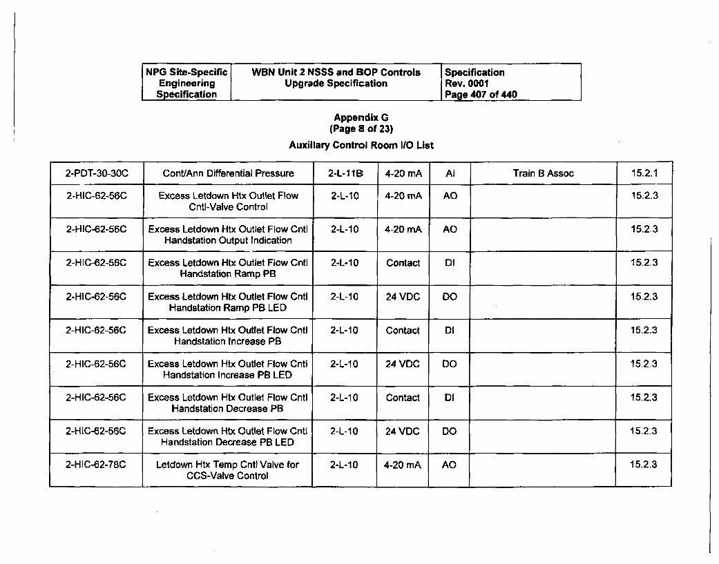
NPG Site-Specific WBN Unit 2 NSSS and EiOP Controls SpecificationEngineering Upgrade Specification Rev. 0001
Specification Page 407 of 440
Appendix G
(Page 8 of 23)
Auxiliary Control Room I/O List
2-PDT-30-30C Cant/Ann Differential Pressure 2-L-11B 4-20 mA Al Train B Assoc 15.2.1
2-HIC-62-56C Excess Letdown Htx Outlet Flow 2-L-10 4-20 mA AO 15.2.3Cntl-Valve Control
2-HIC-62-56C Excess Letdown Htx Outlet Flow Cntl 2-L-10 4-20 mA AO 15.2.3Handstation Output Indication
2-HIC-62-56C Excess Letdown Htx Outlet Flow Cntl 2-L-10 Contact DI 15.2.3Handstation Ramp PB
2-HIC-62-56C Excess Letdown Htx Outlet Flow Cntl 2-L-10 24 VDC DO 15.2.3Handstation Ramp PB LED
2-HIC-62-56C Excess Letdown Htx Outlet Flow Cntl 2-L-10 Contact DI 15.2.3Handstation Increase PB
2-HIC-62-56C Excess Letdown Htx Outlet Flow Cntl 2-L-10 24 VDC DO 15.2.3Handstation Increase PB LED
2-HIC-62-56C Excess Letdown Htx Outlet Flow Cntl 2-L-1 0 Contact DI 15.2.3Handstation Decrease PB
2-HIC-62-56C Excess Letdown Htx Outlet Flow Cntl 2-L-10 24 VOC DO 15.2.3Handstation Decrease PB LED
2-HIC-62-78C Letdown Htx Temp Cntl Valve for 2-L-10 4-20 mA AO 15.2.3CCS-Valve Control
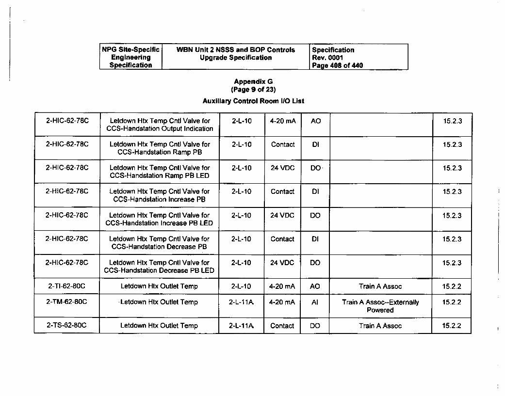
NPG Site-Specific WBN Unit 2 NSSS and BOP Controls SpecificationEngineering Upgrade Specification Rev. 0001Specification Page 408 of 440
Appendix G(Page 9 of 23)
Auxiliary Control Room I/O List
2-HIC-62-78C Letdown Htx Temp Cntl Valve for 2-L-10 4-20 mA AO 15.2.3CCS-Handstation Output Indication
2-HIC-62-78C Letdown Htx Temp Cntl Valve for 2-L-10 Contact DI 15.2.3CCS-Handstation Ramp PB
2-HIC-62-78C Letdown Htx Temp Cntl Valve for 2-L-10 24 VDC DO- 15.2.3CCS-Handstation Ramp PB LED
2-HIC-62-78C Letdown Htx Temp Cntl Valve for 2-L-10 Contact DI 15.2.3CCS-Handstation Increase PB
2-HIC-62-78C Letdown Htx Temp Cntl Valve for 2-L-10 24 VDC DO 15.2.3CCS-Handstation Increase PB LED
2-HIC-62-78C Letdown Htx Temp Cntl Valve for 2-L-10 Contact DI 15.2.3CCS-Handstation Decrease PB
2-HIC-62-78C Letdown Htx Temp Cntl Valve for 2-L-10 24 VDC DO 15.2.3CCS-Handstation Decrease PB LED
2-TI-62-80C Letdown Htx Outlet Temp 2-L-10 4-20 mA AO Train A Assoc 15.2.2
2-TM-62-80C -Letdown Htx Outlet Temp 2-L-11A, 4-20 mA Al Train A Assoc--Externally 15.2.2Powered
2-TS-62-80C Letdown Htx Outlet Temp 2-L-11AA Contact DO Train A Assoc 15.2.2
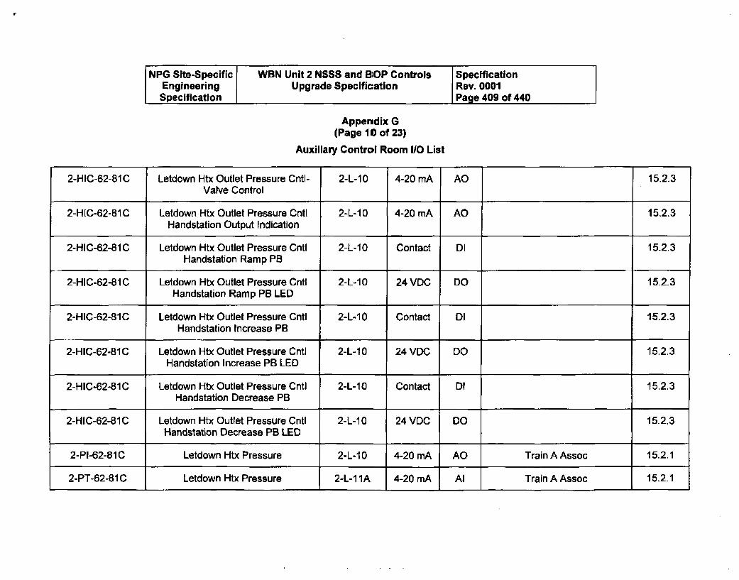
NPG Site-Specific WBN Unit 2 NSSS and BOP Controls SpecificationEngineering Upgrade Specification Rev. 0001Specification Page 409 of 440
Appendix G
(Page 10 of 23)
Auxiliary Control Room I/O List
2-HIC-62-81C Letdown Htx Outlet Pressure Cntl- 2-L-10 4-20 mA AO 15.2.3Valve Control
2-HIC-62-81C Letdown Htx Outlet Pressure Cntl 2-L-10 4-20 mA AO 15.2.3Handstation Output Indication
2-HIC-62-81 C Letdown Htx Outlet Pressure Cntl 2-L-10 Contact DI 15.2.3Handstation Ramp PB
2-HIC-62-81C Letdown Htx Outlet Pressure Cntl 2-L-1 0 24 VDC DO 15.2.3Handstation Ramp PB LED
2-HIC-62-81C Letdown Htx Outlet Pressure Cntl 2-L-10 Contact DI 15.2.3Handstation Increase PB
2-HIC-62-BIC Letdown Htx Outlet Pressure Cntl 2-L-10 24 VDC DO 15.2.3Handstation Increase PB LED
2-HIC-62-81 C Letdown Htx Outlet Pressure Cntl 2-L-10 Contact DI 15.2.3Handstation Decrease PB
2-HIC-62-81C Letdown Htx Outlet Pressure Cntl 2-L-10 24 VDC DO 15.2.3Handstation Decrease PB LED
2-PI-62-81C Letdown Htx Pressure 2-L-10 4-20 mA AO Train A Assoc 15.2.1
2-PT-62-81C Letdown Htx Pressure 2-L-1 1A 4-20 mA Al Train A Assoc 15.2.1
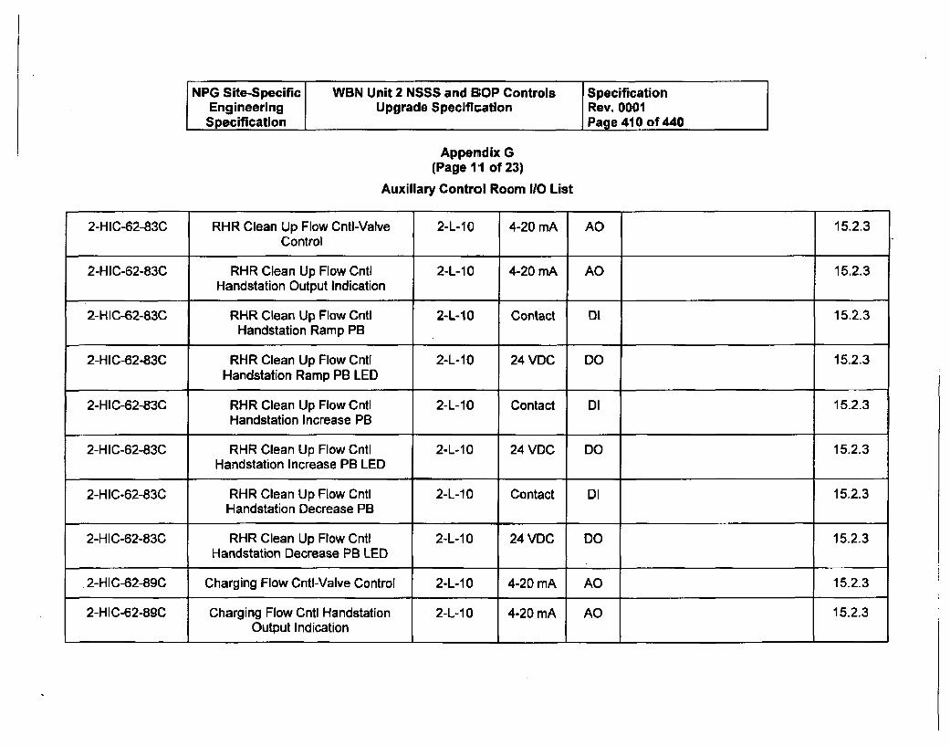
NPG Site-Specific WBN Unit 2 NSSS and BOP Controls SpecificationEngineering Upgrade Specification Rev. 0001Specification Page 410 of 440
Appendix G(Page I1 of 23)
Auxiliary Control Room 1/0 List
2-HIC-62-83C RHR Clean Up Flow Cnti-Valve 2-L-10 4-20 mA AO 15.2.3Control
2-HIC-62-83C RHR Clean Up Flow Cntl 2-L-10 4-20 mA AO 15.2.3Handstation Output Indication
2-HIC-62-83C RHR Clean Up Flow Cntl 2-L-10 Contact Dl 15.2.3Handstation Ramp PB
2-HIC-62-83C RHR Clean Up Flow Cntl 2-L-10 24 VDC DO 15.2.3Handstation Ramp PB LED
2-HIC-62-83C RHR Clean Up Flow Cntl 2-L-10 Contact DI 15.2.3Handstation Increase PB
2-HIC-62-83C RHR Clean Up Flow Cntl 2-L-10 24 VDC DO 15.2.3Handstation Increase PB LED
2-HIC-62-83C RHR Clean Up Flow Cntl 2-L-10 Contact DI 15.2.3Handstation Decrease PB
2-HIC-62-83C RHR Clean Up Flow Cntl 2-L-10 24 VDC DO 15.2.3
Handstation Decrease PB LED
.2-HIC-62-89C Charging Flow Cnti-Valve Control 2-L-10 4-20 mA AO 15.2.3
2-HIC-62-89C Charging Flow Cntl Handstation 2-L-10 4-20 mA AO 15.2.3Output Indication
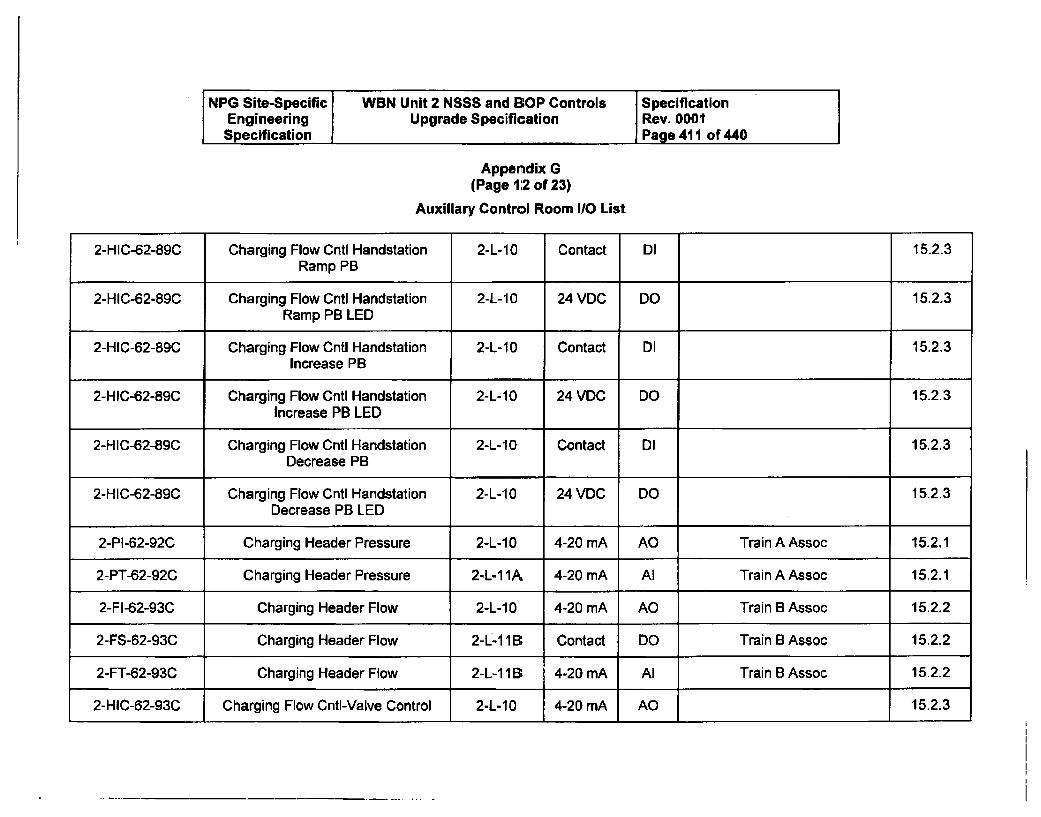
NPG Site-Specific WBN Unit 2 NSSS and BOP Controls SpecificationEngineering Upgrade Specification Rev. 0001
Specification Page 411 of 440
Appendix G(Page 12 of 23)
Auxiliary Control Room IO List
2-HIC-62-89C Charging Flow Cntl Handstation 2-L-10 Contact DI 15.2.3Ramp PB
2-HIC-62-89C Charging Flow Cntl Handstation 2-L-10 24 VDC DO 15.2.3Ramp PB LED
2-HIC-62-89C Charging Flow Cntl Handstation 2-L-10 Contact DI 15.2.3Increase PB
2-HIC-62-89C Charging Flow Cntl Handstation 2-L-10 24 VDC DO 15.2.3Increase PB LED
2-HIC-62-89C Charging Flow Cntl Handstation 2-L-10 Contact DI 15.2.3Decrease PB
2-HIC-62-89C Charging Flow Cntl Handstation 2-L-10 24 VDC DO 15.2.3Decrease PB LED
2-PI-62-92C Charging Header Pressure 2-L-10 4-20 mA AO Train A Assoc 15.2.1
2-PT-62-92C Charging Header Pressure 2-L-1 1A, 4-20 mA Al Train A Assoc 15.2.1
2-FI-62-93C Charging Header Flow 2-L-10 4-20 mA AO Train B Assoc 15.2.2
2-FS-62-93C Charging Header Flow 2-L-1 1 -B Contact DO Train B Assoc 15.2.2
2-FT-62-93C Charging Header Flow 2-L-1 1 B 4-20 mA Al Train B Assoc 15.2.2
2-HIC-62-93C Charging Flow CntI-Valve Control 2-L-10 4-20 mA AO 15.2.3
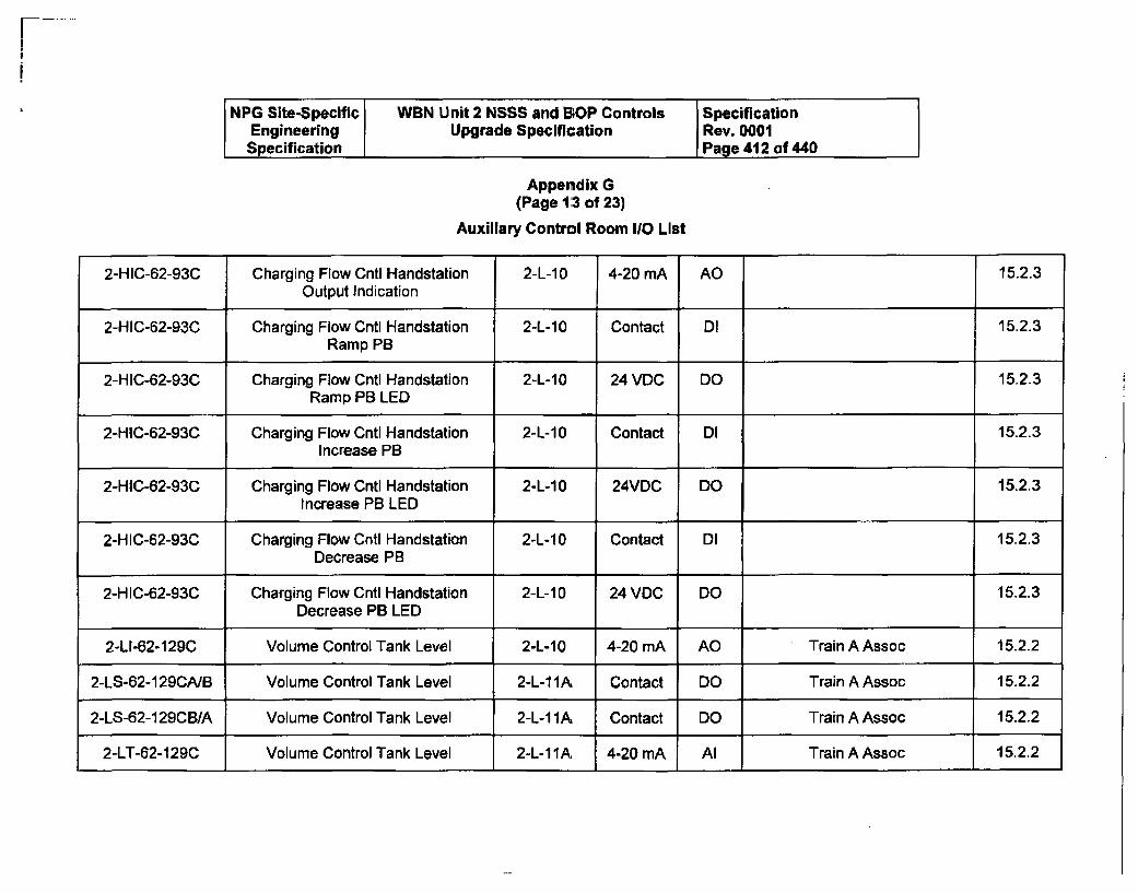
NPG Site-Specific WBN Unit 2 NSSS and 13OP Controls SpecificationEngineering Upgrade Specification Rev. 0001Specification Page 412 of 440
Appendix G(Page 1:3 of 23)
Auxiliary Control Room 1/0 List
2-HIC-62-93C Charging Flow Cntl Handstation 2-L-10 4-20 mA AO 15.2.3Output Indication
2-HIC-62-93C Charging Flow Cntl Handstation 2-L-10 Contact DI 15.2.3Ramp PB
2-HIC-62-93C Charging Flow Cntl Handstation 2-L-10 24 VDC DO 15,2.3Ramp PB LED
2-HIC-62-93C Charging Flow Cntl Handstation 2-L-1 0 Contact DI 15.2.3Increase PB
2-HIC-62-93C Charging Flow Cntl Handstation 2-L-10 24VDC DO 15.2.3Increase PB LED
2-HIC-62-93C Charging Flow Cntl Handstation 2-L-10 Contact DI 15.2.3Decrease PB
2-HIC-62-93C Charging Flow Cntl Handstation 2-L-10 24 VDC DO 15.2.3Decrease PB LED
2-LI-62-129C Volume Control Tank Level 2-L-10 4-20 mA AO Train A Assoc 15.2.2
2-LS-62-129CANB Volume Control Tank Level 2-L-11A Contact DO Train A Assoc 15.2.2
2-LS-62-129CB/A Volume Control Tank Level 2-L-11A Contact DO Train A Assoc 15.2.2
2-LT-62-129C Volume Control Tank Level 2-L-11A 4-20 mA Al Train A Assoc 15.2.2
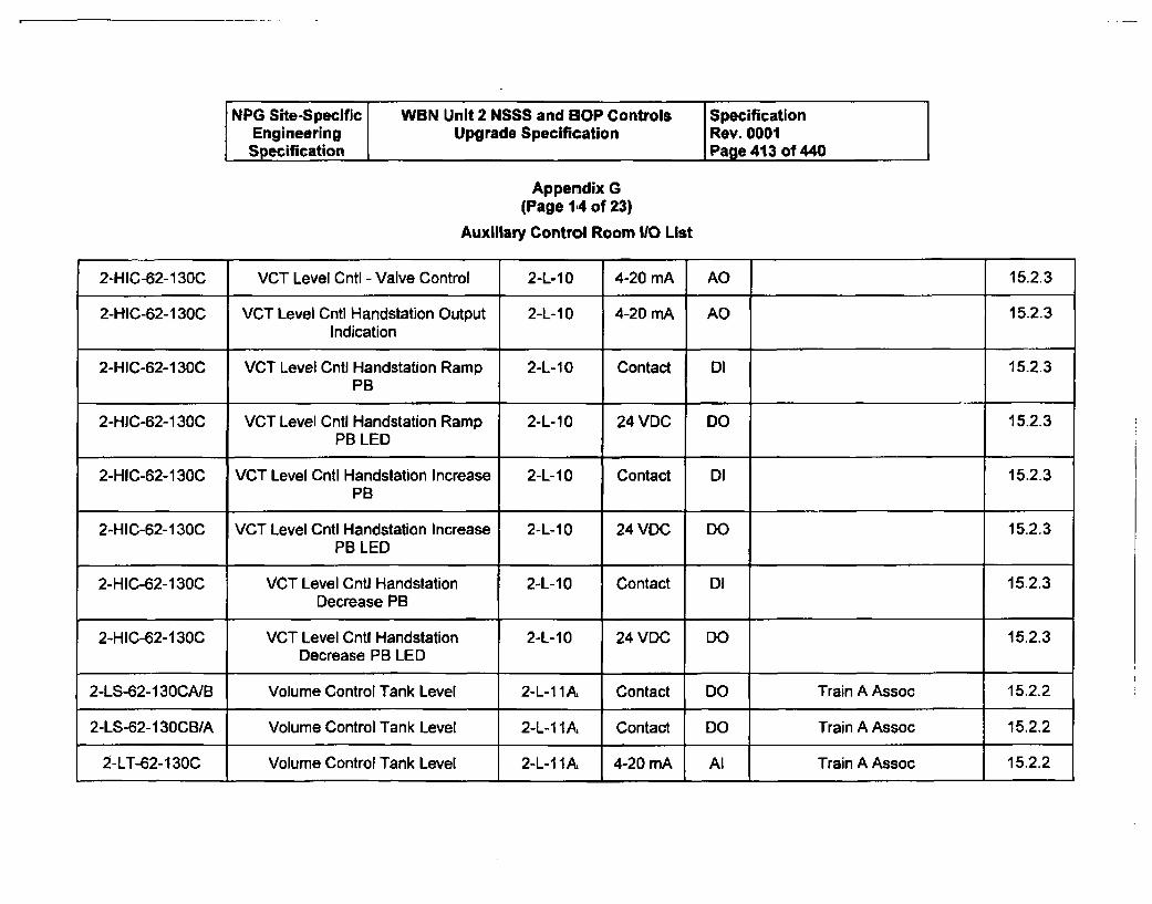
NPG Site-Specific WBN Unit 2 NSSS and BOP Controls SpecificationEngineering Upgrade Specification Rev. 0001
Specification Page 413 of 440
Appendix G
(Page 114 of 23)
Auxiliary Control Room 110 List
2-HIC-62-130C VCT Level Cntl - Valve Control 2-L-10 4-20 mA AO 15.2.3
2-HIC-62-130C VCT Level Cntl Handstation Output 2-L-10 4-20 mA AO 15.2.3Indication
2-HIC-62-130C VCT Level Cntl Handstation Ramp 2-L-10 Contact DI 15.2.3PB
2-HIC-62-130C VCT Level Cntl Handstation Ramp 2-L-10 24 VDC DO 15.2.3PB LED
2-HIC-62-130C VCT Level Cntl Handstation Increase 2-L-10 Contact DI 15.2.3PB
2-HIC-62-130C VCT Level Cntl Handstation Increase 2-L-10 24 VDC DO 15.2.3PB LED
2-HIC-62-130C VCT Level Cntl Handstation 2-L-10 Contact DI 15-2.3Decrease PB
2-HIC-62-130C VCT Level Cntl Handstation 2-L-10 24 VDC DO 15.2.3Decrease PB LED
2-LS-62-I3OCA/B Volume Control Tank Level 2-L-11A Contact DO Train AAssoc 15.2.2
2-LS-62-130CBSA Volume Control Tank Level 2-L-1 1A Contact DO Train A Assoc 15.2.2
2-LT-62-130C Volume Control Tank Level 2-L-1 1A 4-20 mA Al Train A Assoc 15.2.2

NPG Site-Specific WBN Unit 2 NSSS and BOP Controls SpecificationEngineering Upgrade Specification Rev. 0001Specification Page 414 of 440
Appendix G(Page 1:5 of 23)
Auxiliary Control Room 1/0 List
2-FI-62-137C Emergency Boration Flow 2-L-10 4-20 mA Al Train B. Assoc 15.2.1
2-FT-62-137C Emergency Boration Flow 2-L-1 I B 4-20 mA AI Train B Assoc--Sq Rt by the 15.2.1ind scale
2-PI-63-59C SIS Acc Tank 4 Press 2-L-10 4-20 mA AO Train B Assoc 15.2.2
2-PS-63-59C SIS Acc Tank 4 Press 2-L-1 1 B Contact DO Train B Assoc 15.2.2
2-PT-63-59C $IS Acc Tank 4 Press 2-L-1 18B 4-20 mA AI Train B Assoc 15.2.2
2-HIC-63-65C N2 makeup to SIS Accum - Valve 2-L-10 4-20 mA AO 15.2.3Control
2-HIC-63-65C N2 makeup to SIS Accum 2-L-10 4-20 mA AO 15.2.3Handstation Output Indication
2-HIC-63-65C N2 makeup to SIS Accum 2-L-10 Contact DI 15.2.3Handstation Ramp PB
2-HIC-63-65C N2 makeup to SIS Accum 2-L-10 24 VDC DO 15.2.3Handstation Ramp PB LED
2-HIC-63-65C N2 makeup to SIS Accum 2-L-10 Contact DI 15.2.3Handstation Increase PB
2-HIC-63-65C N2 makeup to SIS Accum 2-L-10 24 VDC DO 15.2.3Handstation Increase PB LED
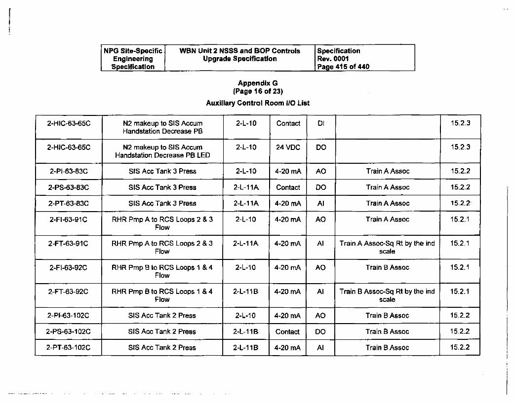
NPG Site-Specific WBN Unit 2 NSSS and BOP Controls SpecificationEngineering Upgrade Specification Rev. 0001Specification Page 415 of 440
Appendix G(Page 116 of 23)
Auxiliary Control Room 110 List
2-HIC-63-65C N2 makeup to SIS Accum 2-L-1 0 Contact DI 15.2.3Handstation Decrease PB
2-HIC-63-65C N2 makeup to SIS Accum 2-L-1 0 24 VDC DO 15.2.3
Handstation Decrease PB LED
2-PI-63-83C 55 Acc Tank 3 Press 2-L-10 4-20 mA AC Train AAssoc 15.2.2
2-PS-63-83C SIS Acc Tank 3 Press 2-L-1 lA Contact DO Train A Assoc 15.2.2
2-PT-63-83C SIS Acc Tank 3 Press 2-L-11A. 4-20 mA Al Train A Assoc 15.2.2
2-FI-63-91C RHR Pmp A to RCS Loops 2 & 3 2-L-10 4-20 mA AO Train A Assoc 15.2.1Flow
2-FT-63-91C RHR Pmp A to RCS Loops 2 & 3 2-L-11A. 4-20 mA Al Train A Assoc-Sq Rt by the ind 15.2.1Flow scale
2-FI-63-92C RHR Pmp B to RCS Loops 1 & 4 2-L-10 4-20 mA AO Train B Assoc 15.2.1Flow
2-FT-63-92C RHR Pmp B to RCS Loops 1 & 4 2-L-11B 4-20 mA Al Train B Assoc-Sq Rt by the ind 15.2.1Flow scale
2-PI-63-102C SIS Acc Tank 2 Press 2-L-10 4-20 mA AO Train B Assoc 15.2.2
2-PS-63-102C SIS Acc Tank 2 Press 2-L-11B. Contact DO Train B Assoc 15.2.2
2-PT-63-102C SIS Acc Tank 2 Press 2-L-111B, 4-20 mA Al Train B Assoc 15.2.2
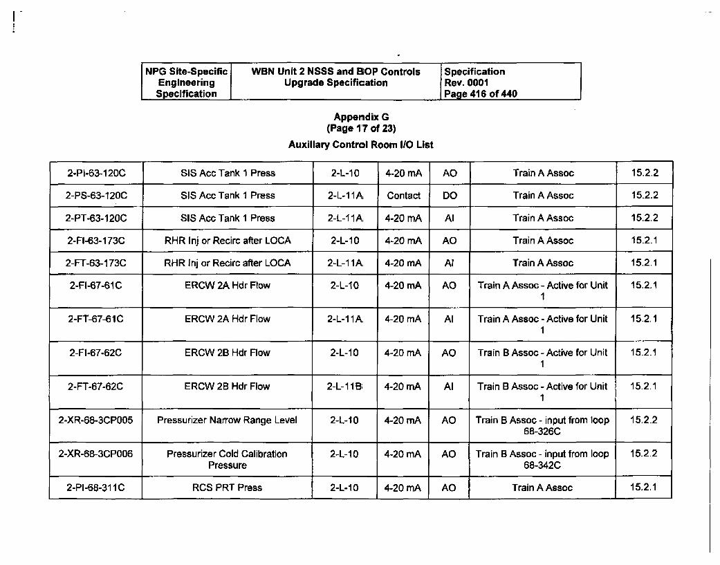
NPG Site-Specific WBN Unit 2 NSSS and BOP Controls SpecificationEngineering Upgrade Specification Rev. 0001Specification Page 416 of 440
Appendix G(Page 17 of 23)
Auxiliary Control Room 10 List
2-PI-63-120C SIS Acc Tank 1 Press 2-L-1-0 4-20 mA AO Train A Assoc 15.2.2
2-PS-63-120C SIS Acc Tank 1 Press 2-L-11A, Contact DO Train A Assoc 15.2.2
2-PT-63-120C SIS Ace Tank 1 Press 2-L-11A 4-20 mA Al Train A Assoc 15.2.2
2-FI-63-173C RHR Inj or Recirc after LOCA 2-L-10 4-20 mA AO Train A Assoc 15.2.1
2-FT-63-173C RHR Jnj or Recirc after LOCA 2-L-11A, 4-20 mA Al Train A Assoc 15.2.1
2-FI-67-61C ERCW 2A Hdr Flow 2-L-10 4-20 mA AO Train A Assoc - Active for Unit 15.2.11
2-FT-67-61C ERCW 2A Hdr Flow 2-L-11A, 4-20 mA Al Train A Assoc - Active for Unit 15.2.11
2-FI-67-62C ERCW 2B Hdr Flow 2-L-10 4-20 mA AO Train B Assoc -Active for Unit 15.2.11
2-FT-67-62C ERCW 2B Hdr Flow 2-L-1 I B; 4-20 mA Al Train B Assoc - Active for Unit 15.2.11
2-XR-68-3CP005 Pressurizer Narrow Range Level 2-L-10 4-20 mA AO Train B Assoc - input from loop 15.2.268-326C
2-XR-68-3CP006 Pressurizer Cold Calibration 2-L-10 4-20 mA AO Train B Assoc - input from loop 15.2.2
Pressure 68-342C
2-PI-68-311C RCS PRT Press 2-L-10 4-20 mA AO Train A Assoc 15.2.1
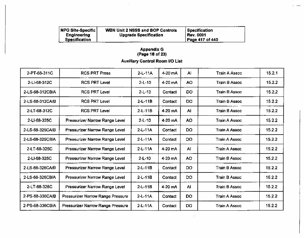
NPG Site-Specific WBN Unit 2 NSSS and B;OP Controls SpecificationEngineering Upgrade Specification Rev. 0001Specification Page 417 of 440
Appendix G(Page 16 of 23)
Auxiliary Control Room 110 List
2-PT-68-31 1C RCS PRT Press 2-L-1 IA. 4-20 mA Al Train A Assoc 15.2.1
2-LI-68-312C RCS PRT Level 2-L-10 4-20 mA AO Train 8 Assoc 15.2.2
2-LS-68-312CB/A RCS PRT Level 2-L-10 Contact DO Train B Assoc 15.2.2
2-LS-68-312CA/B RCS PRT Level 2-L-I1B Contact DO Train B Assoc 15.2.2
2-LT-68-312C0 RCS PRT Level 2-L-11 B 4-20 nA Al Train B Assoc 15.2.2
2-LI-68-325C Pressurizer Narrow Range Level 2-L-1 0 4-20 mA AO Train A Assoc 15.2.2
2-LS-68-325CNB Pressurizer Narrow Range Level 2-L-1 A Contact DO Train A Assoc 15.2.2
2-LS-68-325CB/A Pressurizer Narrow Range Level 2-L-1 IA Contact DO Train A Assoc 15.2.2
2-LT-68-325C Pressurizer Narrow Range Level 2-L-1 IA 4-20 nA Al Train A Assoc 15.2.2
2-LI-68-326C Pressurizer Narrow Range Level 2-L-10 4-20 mA AO Train A Assoc 15.2.2
2-LS-68-326CA/B Pressurizer Narrow Range Level 2-L-1 lB Contact DO Train B Assoc 15.2.2
2-LS-68-326CB1A Pressurizer Narrow Range Level 2-L-11B Contact DO Train B Assoc 15.2.2
2-LT-68-326C Pressurizer Narrow Range Level 2-L-11B 4-20 mA Al Train B Assoc 15.2.2
2-PS-68-336CA1B Pressurizer Narrow Range Pressure 2-L-11A Contact DO Train A Assoc 15.2.2
2-PS-68-336CB1A Pressurizer Narrow Range Pressure 2-L-1 lA Contact DO Train A Assoc 15.2.2
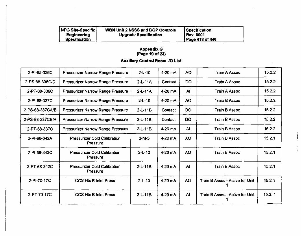
NPG Site-Specific WBN Unit 2 NSSS and BOP Controls SpecificationEngineering Upgrade Specification Rev. 0001Specification Page 418 of 440
Appendix G(Page 19 of 23)
Auxiliary Control Room 110 List
2-PI-68-336C Pressurizer Narrow Range Pressure 2-L-10 4-20 mA AO Train A Assoc 15.2.2
2-PS-68-336CID Pressurizer Narrow Range Pressure 2-L-1 1A, Contact DO Train A Assoc 15.2.2
2-PT-68-336C Pressurizer Narrow Range Pressure 2-L-11 A, 4-20 mA Al Train A Assoc 15.2.2
2-PI-68-337C Pressurizer Narrow Range Pressure 2-L-10 4-20 mA AO Train B Assoc 15.2.2
2-PS-68-337CA/B Pressurizer Narrow Range Pressure 2-L-11 B Contact DO Train B Assoc 15.2.2
2-PS-68-337CB/A Pressurizer Narrow Range Pressure 2-L-1 1 B Contact DO Train B Assoc 15.2.2
2-PT-68-337C Pressurizer Narrow Range Pressure 2-L-11 B 4-20 mA Al Train B Assoc 15.2.2
2-PI-68-342A Pressurizer Cold Calibration 2-M-5 4-20 mA AO Train B Assoc 15.2.1Pressure
2-PI-68-342C Pressurizer Cold Calibration 2-L-1 0 4-20 mA AO Train B Assoc 15.2.1Pressure
2-PT-68-342C Pressurizer Cold Calibration 2-L-1 1 B, 4-20 mA Al Train B Assoc 15.2.1Pressure
2-PI-70-17C CCS Htx B Inlet Press 2-L-10 4-20 mA AO Train B Assoc - Active for Unit 15.2.11
2-PT-70-17C CCS Htx B Inlet Press 2-L-11B; 4-20 rnA Al Train B Assoc -Active for Unit 15.2..11
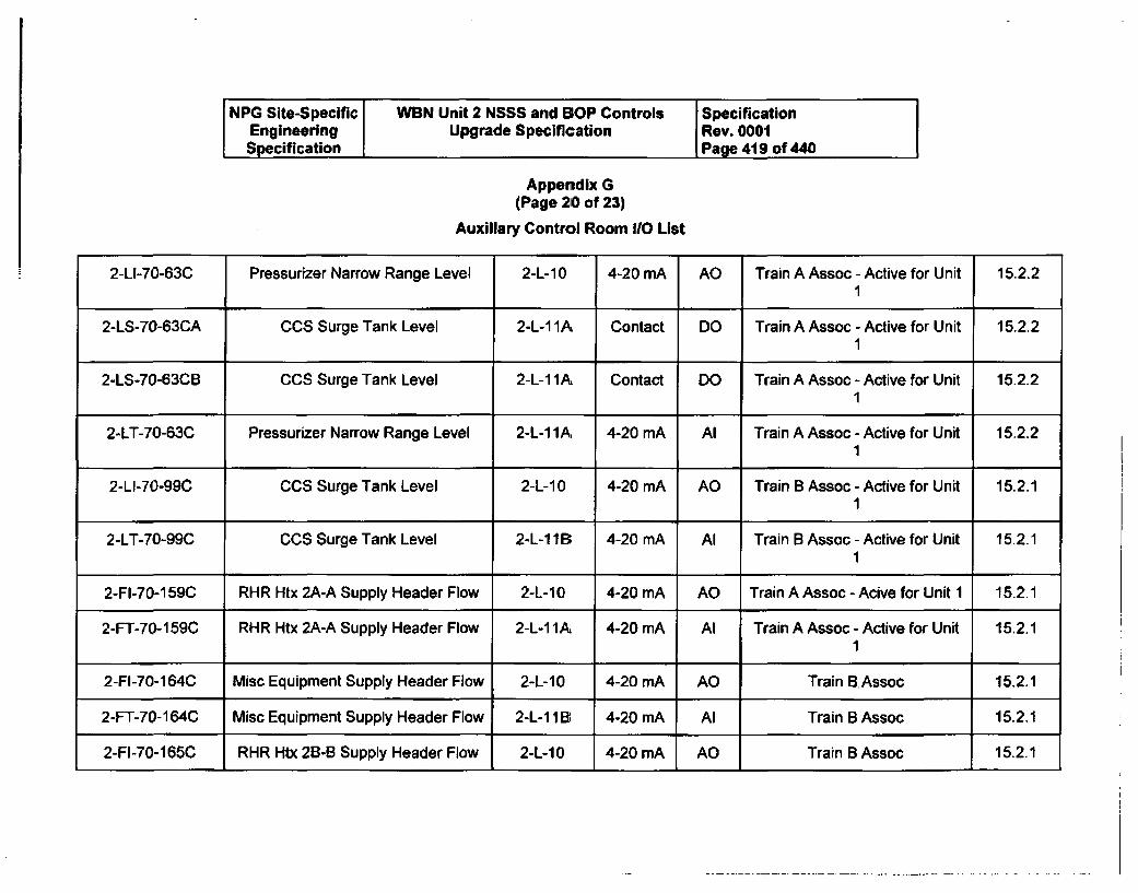
NPG Site-Specific WBN Unit 2 NSSS and BOP Controls SpecificationEngineering Upgrade Specification Rev. 0001Specification Page 419 of 440
Appendix G(Page 210 of 23)
Auxiliary Control Room I/O List
2-LI-70-63C Pressurizer Narrow Range Level 2-L-10 4-20 mA AO Train A Assoc - Active for Unit 15.2.21
2-LS-70-63CA CCS Surge Tank Level 2-L-1 1A Contact DO Train A Assoc - Active for Unit 15.2.21
2-LS-70-63CB CCS Surge Tank Level 2-L-1 IA Contact DO Train A Assoc - Active for Unit 15.2.21
2-LT-70-63C Pressurizer Narrow Range Level 2-L- 1 A 4-20 mA Al Train A Assoc - Active for Unit 15.2.21
2-LI-70-99C CCS Surge Tank Level 2-L-10 4-20 mA AO Train B Assoc - Active for Unit 15.2.11
2-LT-70-99C CCS Surge Tank Level 2-L-118; 4-20 mA Al Train B Assoc - Active for Unit 15.2.11
2-FI-70-159C RHR Htx 2A-A Supply Header Flow 2-L-10 4-20 mA AO Train A Assoc - Acive for Unit 1 15.2.1
2-FT-70-159C RHR Htx 2A-A Supply Header Flow 2-L-1 1A 4-20 mA Al Train A Assoc - Active for Unit 15.2.11
2-FI-70-164C Misc Equipment Supply Header Flow 2-L-10 4-20 mA AO Train BAssoc 15.2.1
2-FT-70-164C Misc Equipment Supply Header Flow 2-L-1 I B 4-20 mA Al Train B Assoc 15.2.1
2-FI-70-165C RHR Htx 28-B Supply Header Flow 2-L-10 4-20 mA AO Train B Assoc 15.2.1
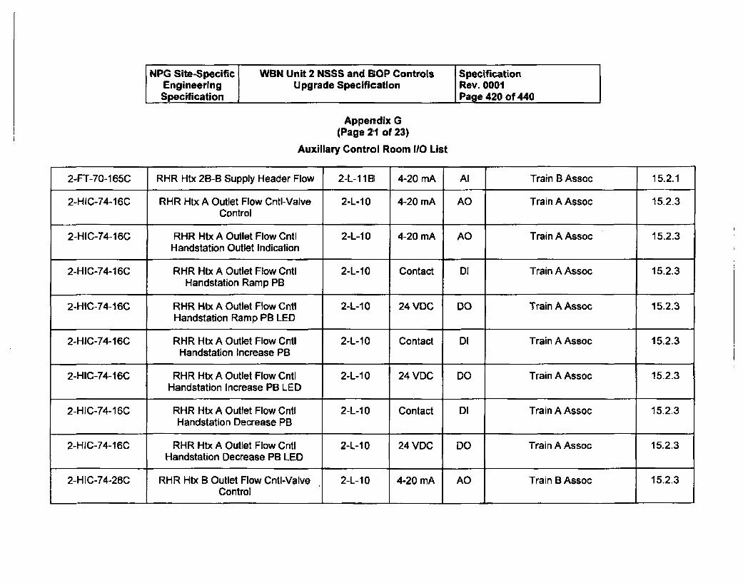
NPG Site-Specific WBN Unit 2 NSSS and BOP Controls SpecificationEngineering Upgrade Specification Rev. 0001Specification J Page 420 of 440
Appendix G
(Page 21 of 23)
Auxiliary Control Room I1O List
2-FT-70-165C RHR Htx 2B-B Supply Header Flow 2-L-11Bl 4-20 mA Al Train B Assoc 15.2.1
2-HIC-74-16C RHR Htx A Outlet Flow Cntl-Valve 2-L-10 4-20 mA AO Train A Assoc 15.2.3Control
2-HIC-74-16C RHR Htx A Outlet Flow Cntl 2-L-10 4-20 mA AO Train A Assoc 15.2.3Handstation Outlet Indication
2-HIC-74-16C RHR Htx A Outlet Flow Cntl 2-L-10 Contact DI Train A Assoc 15.2.3Handstation Ramp PB
2-HIC-74-16C RHR Htx A Outlet Flow Cntl 2-L-10 24 VDC DO Train A Assoc 15.2.3Handstation Ramp PB LED
2-HIC-74-16C RHR Htx A Outlet Flow Cntl 2-L-10 Contact DI Train A Assoc 15.2.3Handstation Increase PB
2-HIC-74-16C RHR Htx A Outlet Flow Cntl 2-L-10 24 VDC DO Train A Assoc 15.2.3Handstation Increase PB LED
2-HIC-74-16C RHR Htx A Outlet Flow Cntl 2-L-10 Contact DI Train A Assoc 15.2.3Handstation Decrease PB
2-HIC-74-16C RHR Htx A Outlet Flow Cntl 2-L-10 24 VDC DO Train A Assoc 15.2.3Handstation Decrease PB LED
2-HIC-74-28C RHR Htx B Outlet Flow CntU-Valve 2-L-10 4-20 mA AO Train B Assoc 15.2.3Control
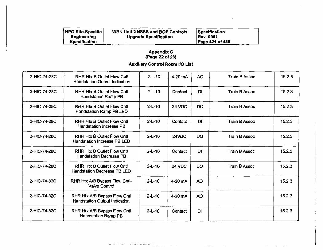
NPG Site-Specific WBN Unit 2 NSSS and BOP Controls SpecificationEngineering Upgrade Specification Rev. 0001Specification Page 421 of 440
Appendix G
(Page 2:2 of 23)
Auxiliary Control Room I/O List
2-HIC-74-28C RHR Htx B Outlet Flow Cntl 2-L-10 4-20 mA AO Train B Assoc 15.2.3Handstation Output Indication
2-HIC-74-28C RHR Htx B Outlet Flow Cntl 2-L-10 Contact DI Train B Assoc 15.2.3Handstation Ramp PB
2-HIC-74-28C RHR Htx B Outlet Flow Cntl 2-L-10 24 VDC DO Train B Assoc 15.2.3Handstation Ramp PB LED
2-HIC-74-28C RHR Htx B Outlet Flow Cntl 2-L-1 0 Contact DI Train B Assoc 15.2.3Handstation Increase PB
2-HIC-74-28C RHR Htx B Outlet Flow Cntl 2-L-10 24VDC DO Train B Assoc 15.2.3Handstation Increase PB LED
2-HIC-74-28C RHR Htx B Outlet Flow Cntl 2-L-1 0 Contact DI Train B Assoc 15.2.3Handstation Decrease PB
2-HIC-74-28C RHR Htx B Outlet Flow Cntl 2-L-1 0 24 VDC DO Train B Assoc 15.2.3Handstation Decrease PB LED
2-HIC-74-32C RHR Htx NB Bypass Flow Cntl- 2-L-1 0 4-20 mA AO 15.2.3Valve Control
2-HIC-74-32C RHR Htx A/B Bypass Flow Cntl 2-L-10 4-20 mA AO 15.2.3Handstation Output Indication
2-HIC-74-32C RHR Htx NB Bypass Flow Cntl 2-L-10 Contact DI 15.2.3Handstation Ramp PB
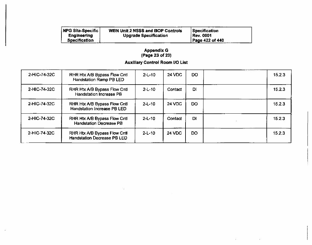
NPG Site-Specific WBN Unit 2 NSSS and 13OP Controls SpecificationEngineering Upgrade Specification Rev. 0001Specification Page 422 of 440
Appendix G(Page 23 of 23)
Auxiliary Control Room 1/0 List
2-HIC-74-32C RHR Htx NB Bypass Flow Cntl 2-L-1 0 24 VDC DO 15.2.3Handstation Ramp PB LED
2-HIC-74-32C RHR Htx A/B Bypass Flow Cntl 2-L-10 Contact DI 15.2.3Handstation Increase PB
2-HIC-74-32C RHR Htx NB Bypass Flow Cntl 2-L-10 24 VDC DO 15.2.3Handstation Increase PB LED
2-HIC-74-32C RHR Htx NB Bypass Flow CntI 2-L-10 Contact DI 15.2.3Handstation Decrease PB
2-HIC-74-32C RHR Htx NB Bypass Flow Cntl 2-L-10 24 VDC DO 15.2.3Handstation Decrease PB LED
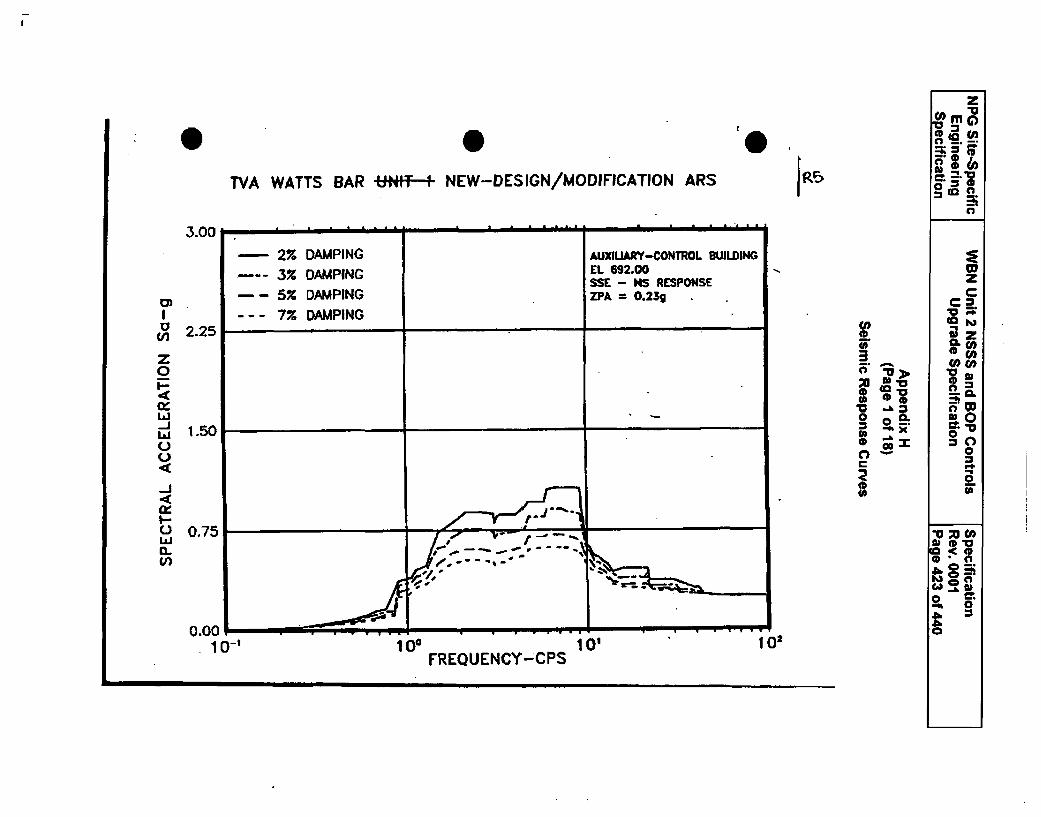
0 0TVA WATTS BAR U,,f - NEW-DESIGN/MODIFICATION ARS
IP,
3.00
tm
z0
La
C)V)
2.25
1.50
0.75
2% DAMPING AUXIUARY-CONTROL BUILDING.3% DAMPING EL 692.00
SSE - NS RESPONSE- 5% DAMPING ZPA 0 O.23g
--- 7% DAMPING
L ________________________________________ ________________________________u_______ ________________n_______________n_______
C'X
0
z
gco
0
V
--CkC0= 0-
0.Q
*00~0=
->
V1
Xs
I I
*0 to
0
I I0.001-10-1
L I _ 10 I • . 2 . . . . .
IFREQUENCY"-CPS 102
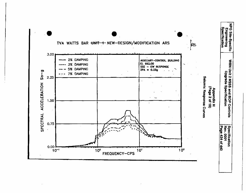
z"a*=
TVA WATTS BAR UtNIT * + NEW-DESIGN/MODIFICATION ARS o
3.00
- 2% DAMPING AUXIUARY-CONTROL BUILDING3% DAMPING EL 692.00 .wSSE - EW RESPONSE
Z-5% DAMPING ZPA 0.23g . I' €a
I -- - 7% DAMPING "o-o 2.25 t.
(CL
z 00,0. > low
La toL-a 1.50 2fo ° =o
1.50<( 0
0 0.75 La--' ¾ U2 t.OI. .1 --- m -.
CL-
0.00110-i 0° 0" 102
FREQUENCY-CPS
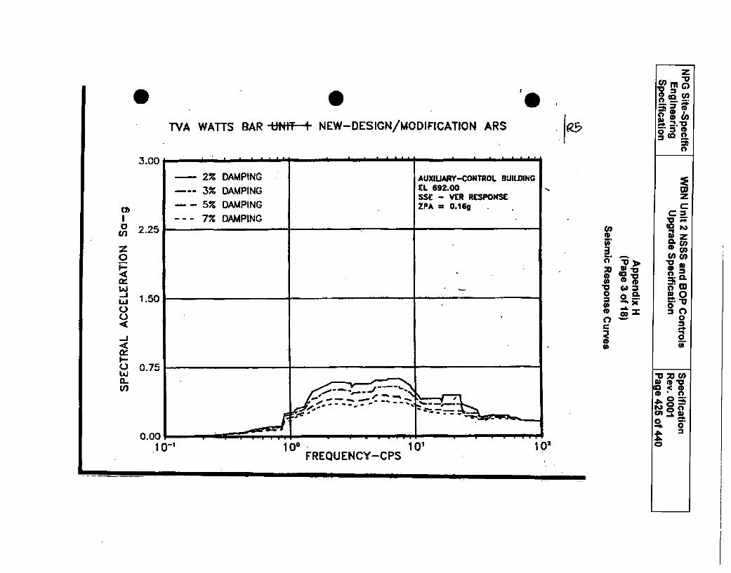
0 0TFVA WATTS BAR Ut;t*T' - NEW-DESIGN/MODIFICATION ARS
I0
frz~l • I I -i i :
3.00 I Y
-2X--- 3%
--- 75%- -- 7%
DAMPINGDAMPINGDAMPINGDAMPING
AUXIUARY-CONTROL BUILDINGEL 692.00SSE - VER RESPONSEZPA = 0.16g
U)
z0
-AJ
0
EL*i-
2.25I
1.50
0.75
coe.
a v
0
w0 O
I0.001-10-I 108 101
FREQUENCY-CPS10,
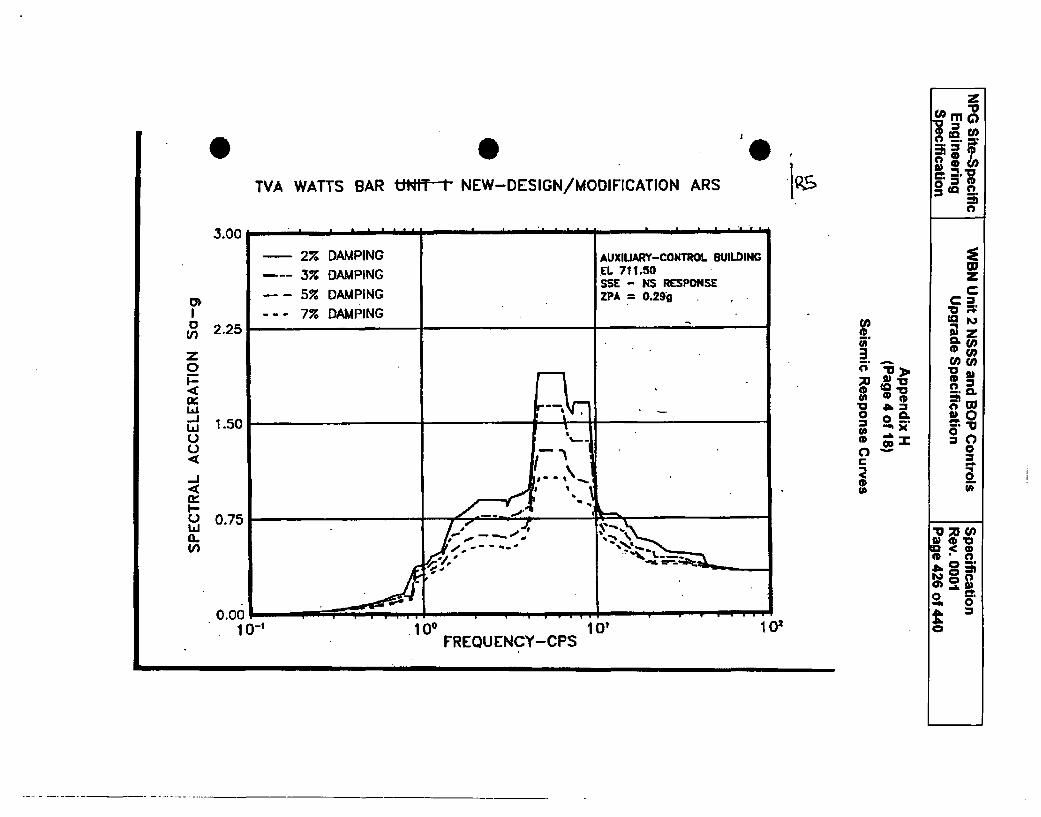
*I
.19.sTVA WATTS BAR tUtNT-t NEW-DESIGN/MODIFICATION ARS
3.00
.CL00 C
CL
0)0
atoz0F:ccLii-ILUUC).4-4.4I-C-,LI~1.CO
2.25
1.50
0.75
CD05.i.00us00UU0C
U(A
0-0
t 0Z
M0*0
o) =~m 0
t=0.00. 1 0-1FREQUENCY-CPS 101
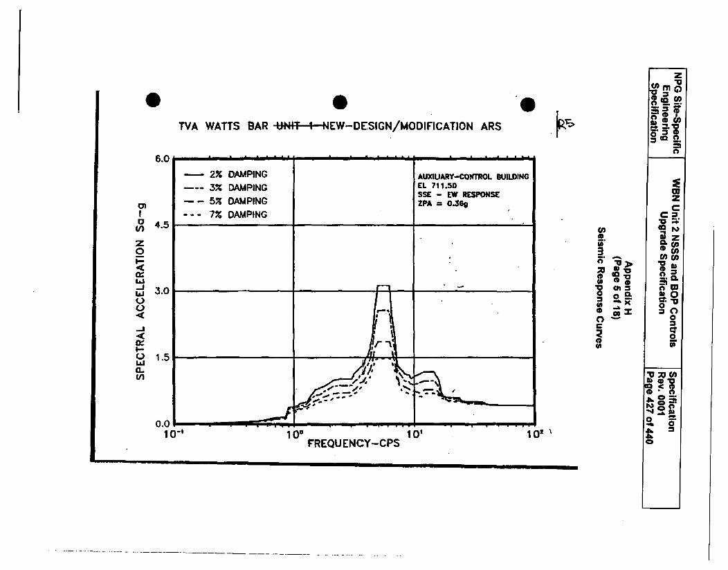
ETVA WATTS BAR Ut•¢fT--1--lEW-DESICN/MODIFICATION ARS
V)
z0
_j
I--
aJ
M-
W)
)ING
102
z
C(a
0to00
ir*
Co
3W
050
.5C. 50*01=~0.-
C3,IV~.
a 0
FREQU ENCY-CPS
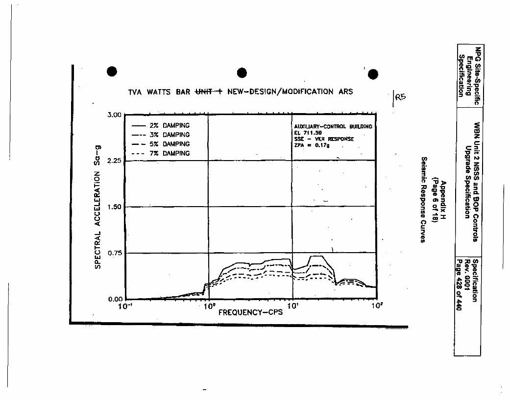
TVA WATTS BAR -UNIT-+ NEW-DESIGN/MODIFICATION ARS
3.00 __-_'".. ._... .
2% DAMPING AUXIUARY-CONTROL BUILDING
3% DAMPING EL 711.50SSE - VER RESPONSE
-- 5% DAMPING ZPA = 0.17gI --- 7% DAMPINGto 2 -2 5
CO)•~-!
zo .5
w
,-U>
300.7
1.50 ,. ..
I 01O000.75
L ai(L
_f. Z, 7l%
Ir %
0.00.10-1 100 010
FREQUENCY-CPS
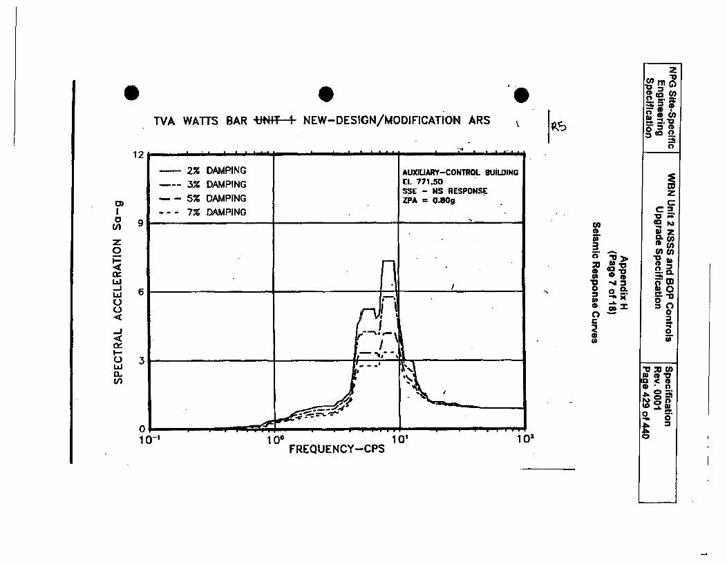
KPTVA WATTS BAR +41.-I- NEW-DESIGN/MODIFICATION ARS
12
(A)
z0
-J
C,0,-J
I-.0/
9
6
3
FA
0
(A
3,d>01'to ,a-43
0!--tl(b
10-1 100 10'lFREQUENCY-CPS
102
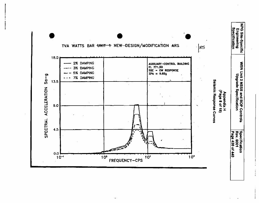
TVA WATTS BAR UN 9F-- NEW-DESIGN/MODIFICATION ARS
c/iz
CL*-J
18.0
13.5
9.0
4.5
z
CO )
CL C
CL
.t0.
00cc
'a CD =
U0~'a
"a M 0
-' 00.0
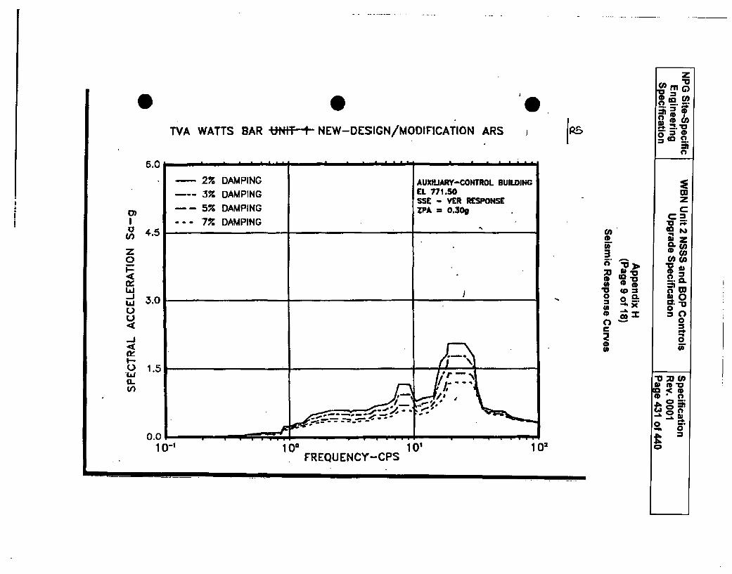
0 0TVA WATTS BAR -UNIfT-t NEW-DESIGN/MODIFICATION ARS i I.,.
6.0
2% DAMPING AUXILIARY-CONTROL BUILDING
3% DAMPING EL 771.50SSE - VER RESPONSE5% DAMPING ZPA = 0.30g
a-- 7%X DAMPINGU)
(I
z0
WV-.IJ
I-
"IL•U.
4.5
3.0
1.5
i
0 o
0~c
zO"a
;;n G
CL W
lw*cn
ct-0
30.'0
taC
co0CD
S 4* 9
i .4 iI
I
0.01-1 01
Ia
101FREQUENCY-CPS
10, 102
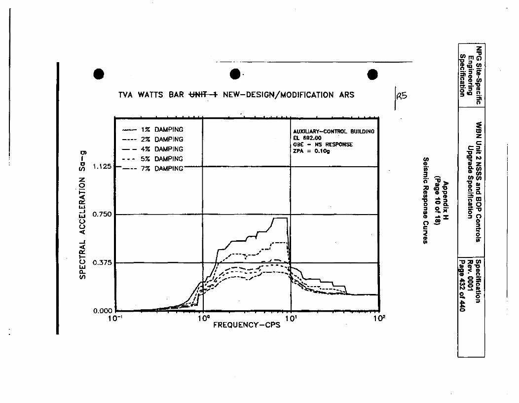
z
aM Ggem•
a."c
TVA WATTS BAR UNITF- NEW-DESIGN/MODIFICATION ARS
1 % APN---- 1% DAMPING AUXIUARY-CONTROL BUILDING W
2% DAMPING EL 692.00 ZOBE - NS RESPONSE C
E) --- 4% DAMPING ZPA = 0.10g "m--- 5% DAMPING CA.,
o 1.125 7% DAMPING CL e""
3emOz co mm
.0,, 0 .4(4Ix oV oLal 0 oL 0
- 0.750ou aoL) 0
0
U 0.1 37
.4 0
0.000-0.
10-' 1001012FREQUENCY'-CPS
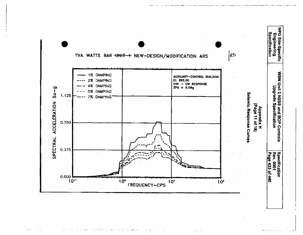
0 0
z
5'0
U,,
z0I-
._J
C)
n-
I--C-)
0..U)
1.125
0-750
0.375
TVA WATTS BAR -Nff-t- NEW-DESIGN/MODIFICATION ARS
1% DAMPING AUXIUARY-CONTROL BUILDING
2% DAMPING EL 692.00OBE - EW RESPONSE4% DAMPING ZPA = 0.09g
- -- 5% DAMPING7% DAMPING
//.,---"., x'r- ,. --'-. ,d,-••t•:• . • •4,.,
'I.. .- . . . . . . ,
1 ?5
'3
0
QZ.
Vla>
0
Go
wzC
"oWinn
0
,00
o_.0
6 00.000
1IU" FREQUENCY-CPS 10, 102
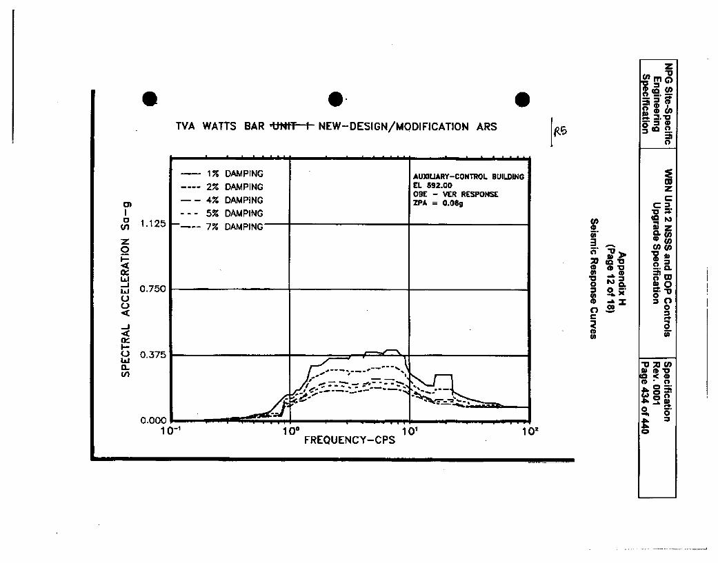
z'v
=mrG)
TVA WATTS BAR Ut;tT 1 NEW-DESIGN/MODIFICATION ARS 0
S1% DAMPING AUXIUARY-CONTROL BUILDING
2% DAMPING EL 592.00 zODE - VER RESPONSE _
o) -- 4% DAMPING ZPA = 0.OgI --- 5% DAMPING "o _ _
1.125 7% DAMPING 0 " z
z I0(
lcow
.l 00.7 =1 0-. 0.1_& X 0o Cc
(a(/
Q- 0.7 , ='m
0
4. 0..00 ' ••
I--0.3750
1 0-1 100 10, I 02
FREOUENCY-CPS
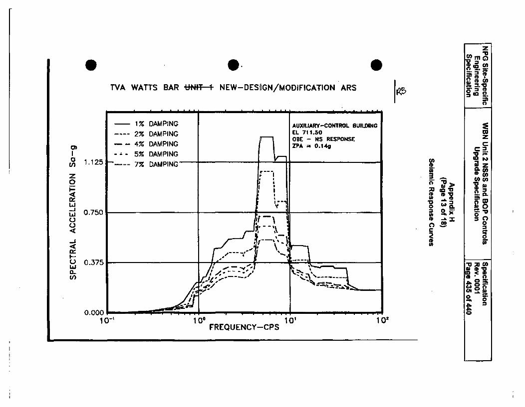
TVA WATTS BAR UtNIT * NEW-DESIJGN/MODIFICATION ARS
0)
w
0-
LVi
1.125,
0.750
0.375
0.000
-3F
*00
3
C>
0
z
moZ
3 9C"
w
CL
R:
mz~0.
a:0& 0::
0
102FREQUENCY-CPS
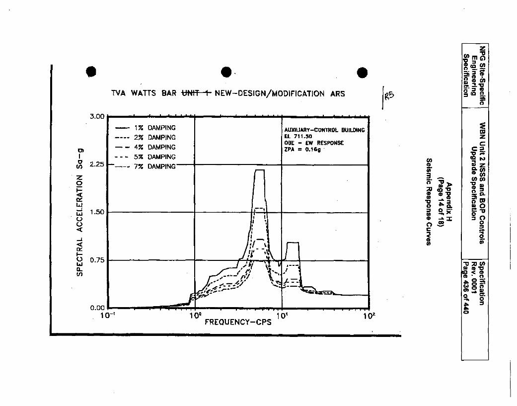
9TVA WATTS BAR UT1t NEW-DESIGN/MODIFICATION ARS
0)I,
I---JLLI
C,)
.-j
I--
haJ01.Un
tov
0
I>
SCL
0
zrnC)
z
CL€-
CL
00
T, M C
n* W
wi
0
00
% S0C<.0 l
I
10'
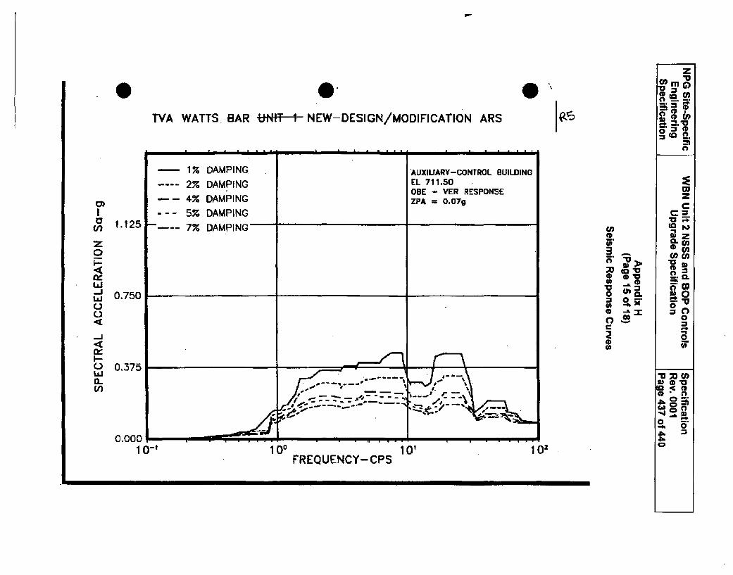
z
TA WATTS BAR -MT-1 NEW-DESIGN/MODIFICATION ARS In
- 1% DAMPING AUXILIARY-CONTROL BUILDING
2% DAMPING EL 711.50ODE - VER RESPONSE W
-- 4% DAMPING ZPA = O.07g Z
I --- 5% DAMPING1-125 7% DAMPING to
0•5. ca•n°
o o_ '0 CDV C--Lai s.0 -a-
j~0.750 8h oiL0
o 0r0
_j 0
0 0.375(L
U0&
0.000. mo ,,
10-' 100 10' 102 3
FREQUENCY-CPS
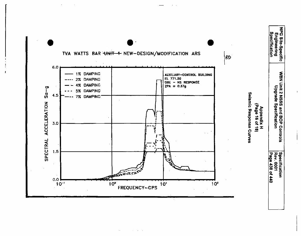
0TVA WATTS BAR -tNf-T- NEW-DESIGN/MODIFICATION ARS
0
z'rnc
co(
to ~
1g06.0 •C • • • 6 m
1% DAMPING2% DAMPING
- _ 4% DAMPING--- 5% DAMPING-- - 7% DAMPING
L)C(Lz)
F
AUXIUARY-CONTROL BUILDINGEL 771.50OBE - HS RESPONSEZPA = 0;3 7g
4.5
3.0
1.5
-. 9 . I.
9rvr-'i'at1 1I I
a,S
C,
S('9U0SsC,Ca(COP
>Ca>
0
z
(CL)
*0
0
0(4)I t\
.,•.
a) SD'"
0 --
-k 0
00.01
10 -1 100 10'FREQUENCY-CPS
102
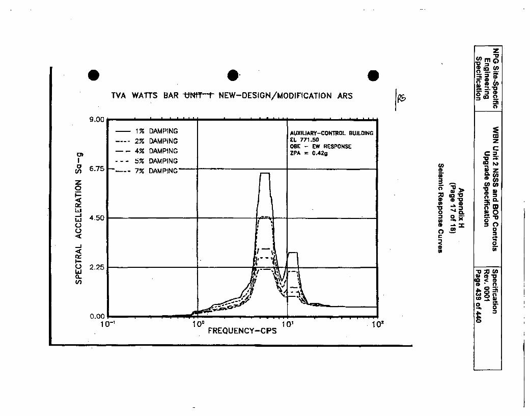
z
0 rn
.. w.. 2 AM Go1kaco
TVA WATTS BAR UNIT NEW-DESIGN/MODIFICATION ARS a
9.00.
-17. DAMPING AUXILIARY-CONTROL BUILDING-2% DAMPING EL 771.50 wzODE - EW R~ESPONSE
-- 4% DAMPING ZPA 0 O.42gI - -- 5% DAMPING wp
-6.75 7 DAMPING 1.
X ** " 'W
Lii 0 0. SOI.. 4.50 -o "0
'1 - 0C r
0LJ 2.25 ,,
0--I-h
.... -0 -.
0.00 a.4 n-It e' n a -t f
IUl IVU 1UFREOUENCY-CPS
IU"
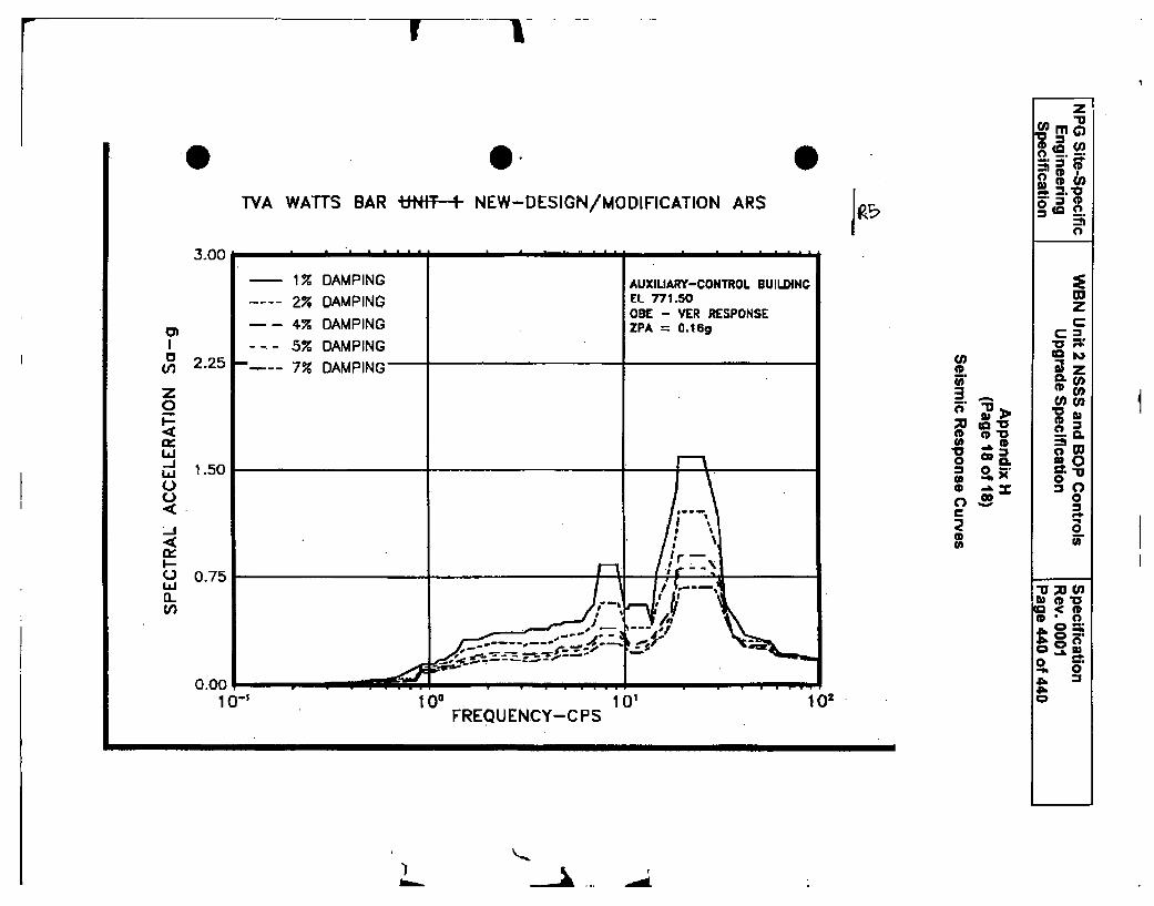
r I
0-M '
. G0
TVA WATTS BAR UNt4F -1- NEW-DESIGN/MODIFICATION ARS 1fZ-1
0)I
z0
La-J
V)
C)
i~in~U)
CD
0
S0
oCcS(D
zC
z
.02
~00
c-t
M
c m
ow
CD 00
• ' _..
I
10-' 100 101 102FREQUENCY-CPS
1-1I1
Attachment 15
Bechtel Power Corporation letter ELS-BM-TVA-U2CC-2011-0002,"Application for Withholding Proprietary Information from Public Disclosure,
Material Requisition 25402-011-MRA-JDOI-00001, Revision 0, NSSSand BOP Controls Upgrade" (Proprietary)
August 22, 2011
U.S. Nuclear Regulatory CommissionDocument Control Desk11555 Rockville PikeRockville, MD 20852
Letter No.: ELS-BM-TVA-U2CC-2011-0002
Application for Withholding Proprietary Information from Public Disclosure
Subject: Material Requisition 25402-01 1-MRA-JD01-00001, Revision 0, NSSS and BOPControls Upgrade (Proprietary)
Attention: Document Control Desk
Bechtel Power Corporation, pursuant to the attached affidavit, hereby requests withholding ofthe proprietary information marked as such in the above-referenced document. The affidavit,which accompanies this letter, sets forth the basis on which Bechtel Power Corporation mayrequest the subject information to be withheld from public disclosure by the Commission andaddresses with specificity the considerations listed in paragraph (b)(4) of 10 CFR Section 2.390of the Commission's regulations ("Section 2.390").
Please also find attached a version of the above-referenced document that we have marked inaccordance with the applicable requirements of Section 2.390. The first page of the documenthas been so marked and each successive page thereafter that contains information that we areseeking to withhold from public disclosure has also been marked accordingly. In addition, wehave bracketed such information on each of the foregoing, subject pages.
Correspondence with respect to the proprietary aspects of the application for withholding or theBechtel affidavit should reference this letter, and should be addressed to Robert Exton, NuclearProcurement Operations Manger, Bechtel Power Corporation, 5275 Westview Drive Frederick,Maryland, 21703-8306.
Very truly yours,
Robert Exton
Nuclear Procurement Operations Manager
Enclosures
BECHTEL POWER CORPORATION 5275 Westview DriveFrederick, MD 21703-8306 USA
tel (301) 2.28-6000
Reference: Bechtel Letter No. ELS--BM-TVA-U2CC-2011-0002
AFFIDAVIT
Before me, the undersigned authority, personally appeared Robert Exton, who, being by meduly sworn according to law, deposes and says that he is authorized to execute this Affidavit onbehalf of Bechtel Power Corporation, and that the averments of fact set forth in this Affidavit aretrue and correct to the best of his knowledge, information, and belief:
Robert ExtonNuclear Procurement Operations Manager
Swo n to and subscribed before meTh~iday of August 2011
Notary Public
VICKIE W. CRESAPNOTA RlV PUBLIC
FREDEi'RICK COUINTV /
MV COIMMISSiON I'pPIRI,:S...... .
Reference: Bechtel Letter No. ELS--BM-TVA-U2CC-2011-0002
1) I am Robert Exton, and as such, with respect to the Watts Bar 2 Nuclear Plant ject, I havebeen delegated the function of reviewing proprietary information sought to be withheldfrom public disclosure in connection with procurement materials to be included nuclearpower plant licensing and rule making proceedings for this project, and am authorized toapply for its withholding on behalf of Bechtel Power Corporation.
2) I am making this Affidavit in conformance with the provisions of 10 CFR Section 2.390 ofthe Commission's regulations and in conjunction with the Bechtel Application forWithholding Proprietary Information from Public Disclosure accompanying this Affidavit.
3) I have personal knowledge of the criteria and procedures utilized by Bechtel PowerCorporation in designating information as a trade secret, privileged or as confidentialcommercial or financial information.
4) Pursuant to the provisions of paragraph (b)(4) of Section 2.390 of the Commission'sregulations, the following is furnished for consideration by the Commission in determiningwhether the information sought to be withheld from public disclosure should be withheld.
(i) The information sought to be withheld from public disclosure is owned by Bechteland has been held in confidence by Bechtel Power Corporation, subject to theconfidential use thereof by Tennessee Valley Authority.
(ii) The information sought to be withheld from public disclosure includes vendorsourcing and pricing information of a type customarily held in confidence byBechtel Power Corporation and its customers and not normally disclosed to thepublic.
(iii) Its use by a competing company would reduce the ability of Bechtel PowerCorporation and its customers to ensure a fair and competitive bidding process forfuture work.