arema mre 2012 volume 1 section 3 8 3 9
TRANSCRIPT

Joining of Rail
© 2012, American Railway Engineering and Maintenance-of-Way Association
AREMA Manual for Railway Engineering 4-3-35
1
3
4
3.7.4.6 Non-Running Rails
a. It is permissible to make exothermic or braze connections to any location on a non-running rail. This includes the base of the rail.
b. Crop rail to remove all propulsion bonds attached to the base of non-running rails prior to any reuse as a running rail. The entire weld and heat affected zone must be removed prior to reuse.
SECTION 3.8 SPECIFICATIONS FOR BONDED INSULATION RAIL JOINTS1
— 1996 —
3.8.1 SCOPE (1996)
These specifications cover the design, materials, fabrication and in-plant testing of bonded insulated rail joints.
3.8.2 ENGINEERING DRAWINGS (1996)
The manufacturer shall submit to the purchaser, for approval, drawings showing the material description, dimensions, fabrication tolerances and assembly methods where required.
1 References, Vol. 97, p. 43.
Figure 4-3-15. Minimum Recommended Bond-to-Bond Spacing(Head of rail removed for clarity)

Rail
© 2012, American Railway Engineering and Maintenance-of-Way Association
4-3-36 AREMA Manual for Railway Engineering
3.8.3 INSPECTION (1996)
a. The purchaser’s authorized representatives shall have free entry to the manufacturer’s plant to inspect the processing and testing of all bonded insulated joints and/or their components. The manufacturer shall provide test specimens to satisfy the purchaser that the bonded insulated joints and/or their components are being supplied in accordance with this specification. Results of all required qualification tests, acceptance tests and production inspections shall be made available to the purchaser prior to shipment unless otherwise stated by the purchaser.
b. The manufacturer shall provide the purchaser with necessary copies of his quality assurance manual, for the purchaser’s review and approval. Upon request, the manufacturer shall provide the purchaser with access to documentation of the active use and findings of the quality assurance procedures.
3.8.4 MATERIALS (1996)
3.8.4.1 General
All bonded insulated joints and/or components shall be new and conform to the requirements specified herein unless otherwise specified by the purchaser. All materials shall conform to the dimensional requirements for the rail section specified by the purchaser.
3.8.4.2 Full Contact Joint Bars
Joint bars for bonded insulated joints shall conform to the configuration of the rail section specified by the purchaser with allowances being made for the insulating material to be used and shall be fabricated from material which meets or exceeds the mechanical properties and workmanship requirements of the current AREMA “Specifications for Quenched Carbon Steel Joint Bars, Microalloyed Joint Bars and Forged Compromise Joint Bars” except as noted below. The fishing height of the joint bar with insulation shall be controlled to within +0 inch to –1/32 inch of the rail section specified. The contact surface of the joint bars adjacent to the rail shall be smooth and straight within a tolerance of ±1/32 inch using a 36 inch straight edge. No branding or other raised surfaces shall be permitted on the contact surfaces. All holes shall be deburred and conform to the size, tolerances and locations specified by the purchaser. Alternate metallic or non-metallic joint bars shall be used if specified by the purchaser.
3.8.4.3 Rail
When prefabricated bonded insulated joints are ordered, and rail is furnished by the manufacturer, the rail used in fabricating the bonded insulated joints shall conform to the chemical composition, mechanical properties, and workmanship requirements of the current Section 2.1, Specifications for Steel Rails. The use of high-strength rails for bonded insulated joints is recommended. The rail shall be saw cut with a variation in end squareness of not more than 1/32 inch. The lengths and drilling of each rail shall be as specified by the purchaser. All burrs from sawing and drilling shall be removed. To the extent possible, adjacent sawed ends of the rail shall be jointed by the bonded insulated joint bars. All raised letters, numerals, etc., within the joint area shall be removed, by grinding, to conform to the existing rail section prior to joint assembly. Should standard rail be utilized, end hardening is recommended and shall be in accordance with Section 2.1, Specifications for Steel Rails, Paragraph 2.1.17.1; or, an alternate method if approved by the purchaser.
3.8.4.4 Insulating Materials
All insulation materials shall have electrical characteristics such that completed joints will meet or exceed the dielectric requirements of the AREMA Signal Manual, Part 14.5.1, Paragraph D, and the Electrical Tests specified in Article 3.8.7.3. End post size shall be as specified by the purchaser with a thickness tolerance of +1/32 inch.
3.8.4.5 Fasteners
The bonded insulated joint shall be designed to be joined together with an adhesive and bolted together with six high-strength bolts of a diameter to be specified by the purchaser. Every other bolt shall be reversed with the nut or fastener on the opposite

Joining of Rail
© 2012, American Railway Engineering and Maintenance-of-Way Association
AREMA Manual for Railway Engineering 4-3-37
1
3
4
side of the rail. The bolts, nuts, and washers, if required, shall conform to the chemical and mechanical requirements of ASTM Specification A90, or A325, as applicable, and have Class 2A and 2B thread fits. An alternate equivalent fastening system shall be used if specified by the purchaser.
3.8.4.6 Adhesive
The structural adhesive used as the bonding agent shall produce a minimum lap shear strength of 3,500 psi at 75 degrees F as per test prescribed in ASTM D-1002 (metal to metal). Adhesive shall be capable of meeting the above requirements for a period of one year from date of manufacture when stored as specified by the manufacturer. A corrosion inhibitor shall be included in the adhesive formulation.
3.8.5 WORKMANSHIP (1996)
3.8.5.1 General
The glue-bonded insulated joint is an assembly of insulating materials, steel and adhesive. Its design is for these dissimilar materials to perform as a homogeneous product. To accomplish this, care must be taken to ensure that quality control procedures are used and that no voids exist in the joint area.
3.8.5.2 Contact Surfaces
The steel contact surfaces of the bars and rail shall be cleaned to bright metal by an approved method, such as sand blasting. All grit and other residues must be removed from the steel contact surfaces to be bonded.
3.8.5.3 Adhesive
Enough adhesive must be used to completely cover the entire contact surfaces of the joint bars and rail and allow some excess adhesive to be squeezed out along the entire perimeter of the joint, when the joint is assembled. Any excess adhesive should be dressed around the perimeter and used to cover the bolt heads and nuts. The assembled joint shall be cured in accordance with the manufacturer’s recommendations.
3.8.5.4 Rail Ends and Bolt Holes
The rail ends shall be saw cut with a variation in end squareness of not more than 1/32 inch. Sharp edges and burrs shall be removed by grinding. The bolt holes shall be free of sharp edges, burrs, loose scale, shavings and other foreign matter.
3.8.5.5 Fastener Torque
Fasteners must be tightened to required torque, following manufacturer’s suggested sequence and procedures.
3.8.6 DIMENSIONAL TOLERANCE (1996)
3.8.6.1 Overall Straightness
Assembled joints shall not deviate from a straight line by more than the tolerances provided in Table 4-3-14. The deviation from a straight line must be reasonably uniform. Kinks are unacceptable except as provided in Article 3.8.6.2.c.
Table 4-3-14. Tolerances for Assembled Joints
Length of Rail and Joint 13 Feet to 39 Feet
Over 39 Feet to 60 Feet
Maximum mid-ordinate from a straight line for either side sweep or upsweep 3 inch 2 inch

Rail
© 2012, American Railway Engineering and Maintenance-of-Way Association
4-3-38 AREMA Manual for Railway Engineering
3.8.6.2 Joint Area
a. The vertical alignment of the assembled joint shall be level, within a tolerance of +0.030 inch crown, as measured with a 36 inch straight edge. Dip shall not be permitted. See Figure 4-3-16 and Figure 4-3-17.
b. The horizontal alignment of the assembled joint shall be straight, within a tolerance of 0.040 inch as measured with a 36 inch straight edge. See Figure 4-3-18.
c. Vertical offset between the two rail ends shall not exceed 0.030 inch. Horizontal offset (kink) shall not exceed 0.020 inch.
3.8.7 QUALIFICATION TESTING (1996)
3.8.7.1 General
a. Three bonded insulated joints shall be tested by the material components manufacturer as follows: two bonded insulated joints shall be tested as specified in Article 3.8.7.2 and the remaining bonded insulated joint shall be tested first in accordance with Article 3.8.7.3 then subjected to a test as specified in Article 3.8.7.4. After completion of the rolling load test, the joint shall be resubjected to the electrical resistance test.
b. Qualification testing shall not commence until the engineering drawings are approved by the purchaser. For each design and/or material change, the material components manufacturer shall be required to perform these qualification tests only on a one-time basis unless otherwise agreed upon by both the manufacturer and the purchaser.
c. If the bonded insulated joint being purchased has been previously qualified, the manufacturer shall provide access to the test results to subsequent purchasers. If the manufacturer makes any changes in the materials or the design, the manufacturer shall requalify the new joint through the testing prescribed herein before production is resumed.
3.8.7.2 Longitudinal Compression Test (For Qualification Only)
a. Two bonded insulated joints shall be completely assembled per manufacturer’s recommendations. Two pieces of rail of the prescribed rail section, each 2 feet long, shall be utilized for each joint. Each joint assembly shall then be sawed in half where the rails are butted together. The sawing shall be done in a manner which will prevent overheating and damage to the bonding agent, and the cut shall be perpendicular to the center line of the top of the rail with a tolerance of ±1 degree. The sawn ends of the bars at one end of the test piece, and the end of rail at the other, shall have fair bearing in the test machine to ensure that the loading and reaction are through the centroid of the rail, and parallel to its axis.
b. Load shall be applied parallel to the running surface of the rail in increments of 25,000 pounds. Each load increment shall be maintained constant until the longitudinal deflection of the rail ceases before increasing the load by the next increment.
c. The load shall be increased in these increments until a total load of 650,000 lb is attained for rail weights of 132 lb or greater, or failure occurs. For rails less than 132 lb, a total load of 600,000 lb shall be used. At each increment of loading, the load and differential movement of the rail and joint bars, measured to 0.001 inch, shall be recorded. If an alternate method of performing this test is used, it shall be submitted to the purchaser for prior approval.
d. The acceptance criterion for the longitudinal compression test shall be as follows: At no time shall any of the bonded insulated joints show any indication of slippage during or before the total prescribed load for the rail section involved is applied to the joint. At the completion of the test, after the load on the rail has been released, the relative position of the rail and joint bar shall be within 0.020 inch of its original value.

Joining of Rail
© 2012, American Railway Engineering and Maintenance-of-Way Association
AREMA Manual for Railway Engineering 4-3-39
1
3
4
Figure 4-3-16. Elevation of Joint Showing Misalignment Tolerance in Vertical Alignmentper Article 3.8.6.2
Figure 4-3-17. Elevation of Joint Showing Misalignment Tolerance in Vertical Alignmentper Article 3.8.6.2
Figure 4-3-18. Plan View of Joint Showing Misalignment Tolerance in Horizontal Alignment per Article 3.8.6.2

Rail
© 2012, American Railway Engineering and Maintenance-of-Way Association
4-3-40 AREMA Manual for Railway Engineering
3.8.7.3 Electrical Resistance Test
3.8.7.3.1 General
A rail joint shall be fully assembled in accordance with manufacturer’s recommendations on two lengths of rail for an electrical resistance test. The dry rail and joint assembly shall be supported on dry nonelectrical conducting material.
3.8.7.3.2 Megohmmeter Test (For Qualification and In-plant Acceptance)
Apply 500 volts, D.C. rail to rail and each rail to one bar, each test for a duration of five (5) seconds according to either of the following:
a. Method 1: Measure the actual current flow (I) through the joint to the nearest 0.1 microampere and record. Calculate the resistance (R) using the formula:
, or
b. Method 2: Use a megohmmeter that reads directly in megohms (resistance).
The acceptance criterion for these tests shall be a minimum resistance of ten (10) megohms.
3.8.7.3.3 High Potential Test (Qualification only, and for spot checks as specified by the customer.)
a. Apply 3000 volts, 60 Hz, A.C., RMS, rail to rail which shall be held for a duration of not less than 60 seconds.
The acceptance criterion shall be that there shall be no flashover or puncture through the insulation which is evident by failure to maintain the voltage through the time stipulated.
3.8.7.4 Rolling Load Test (For Qualification Only)
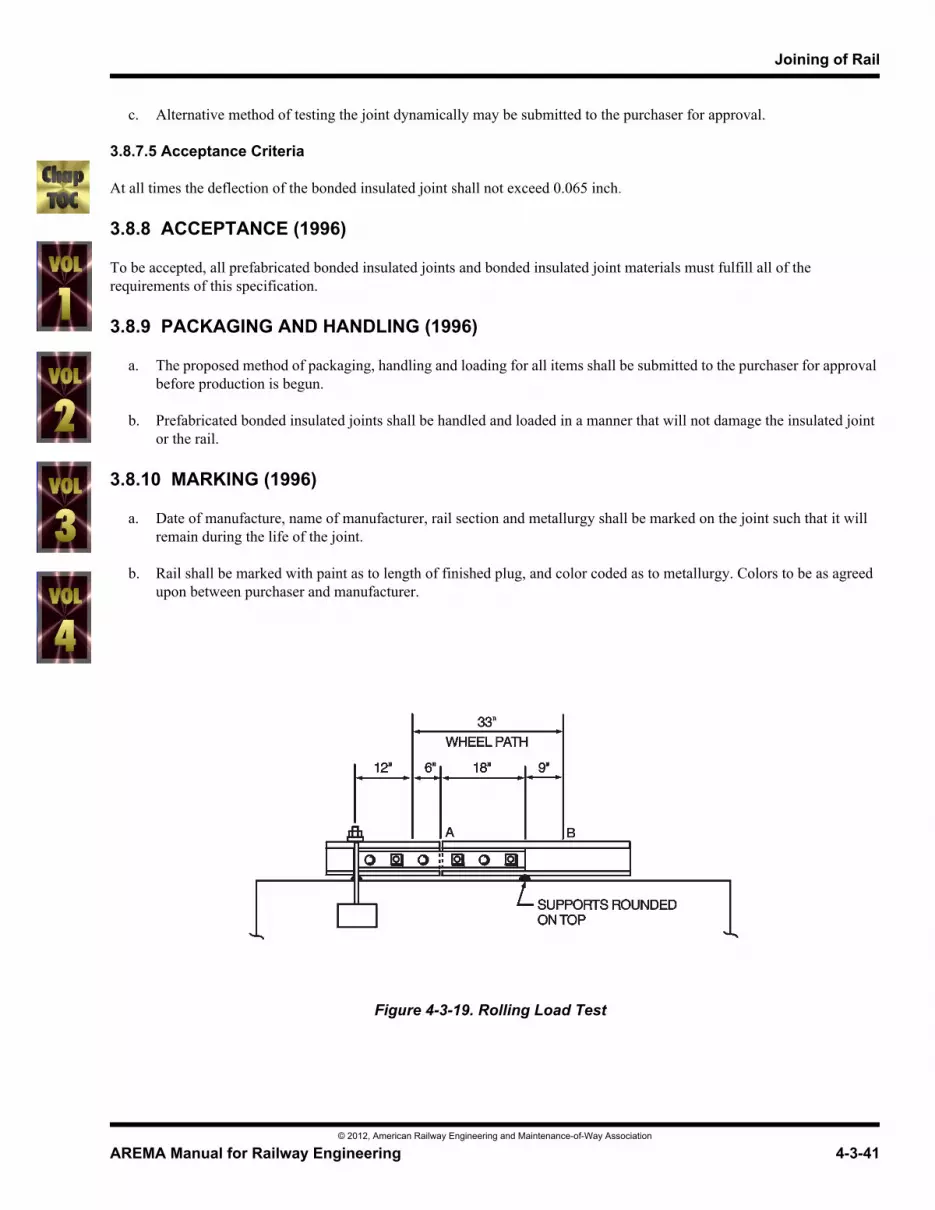
a. The bonded joint shall be mounted on a 33 inch stroke rolling load test machine and supported on 36 inch centers with the joint centered between supports.
b. A wheel load of 44,000 lb shall be applied to the rail. The stroke shall have a range of 33 inches, centered as shown on Figure 4-3-19. The load on the rail shall be applied for 2,000,000 cycles and the deflection of the rail at the center line of rail shall be measured and recorded when the wheel load is over both points A and B for every 500,000 cycles and recorded to the nearest 0.001 inch.
R ohms( ) 500 volts( )I amps( )
--------------------------- where 1 megohm 1,000,000 ohms= =
Joining of Rail
© 2012, American Railway Engineering and Maintenance-of-Way Association
AREMA Manual for Railway Engineering 4-3-41
1
3
4
c. Alternative method of testing the joint dynamically may be submitted to the purchaser for approval.
3.8.7.5 Acceptance Criteria
At all times the deflection of the bonded insulated joint shall not exceed 0.065 inch.
3.8.8 ACCEPTANCE (1996)
To be accepted, all prefabricated bonded insulated joints and bonded insulated joint materials must fulfill all of the requirements of this specification.
3.8.9 PACKAGING AND HANDLING (1996)
a. The proposed method of packaging, handling and loading for all items shall be submitted to the purchaser for approval before production is begun.
b. Prefabricated bonded insulated joints shall be handled and loaded in a manner that will not damage the insulated joint or the rail.
3.8.10 MARKING (1996)
a. Date of manufacture, name of manufacturer, rail section and metallurgy shall be marked on the joint such that it will remain during the life of the joint.
b. Rail shall be marked with paint as to length of finished plug, and color coded as to metallurgy. Colors to be as agreed upon between purchaser and manufacturer.
Figure 4-3-19. Rolling Load Test

Rail
© 2012, American Railway Engineering and Maintenance-of-Way Association
4-3-42 AREMA Manual for Railway Engineering
SECTION 3.9 SPECIFICATIONS FOR NON-BONDED ENCAPSULATED INSULATED RAIL JOINTS1
— 1996 —
3.9.1 SCOPE (1996)
These specifications cover the design, materials, fabrication, and in-plant testing of nonbonded encapsulated insulated rail joints for current AREMA rail sections.
3.9.2 ENGINEERING DRAWINGS (1996)
The manufacturer shall submit to the purchaser, for approval, drawings showing the material description, dimensions, fabrication tolerances and assembly methods where required.
3.9.3 INSPECTION (1996)
a. The purchaser’s authorized representatives shall have free entry to the manufacturer’s plant to inspect the processing and testing of all non-bonded encapsulated insulated joints and/or their components. The manufacturer shall provide test specimens to satisfy the purchaser that the nonbonded encapsulated insulated joints and/or their components are being supplied in accordance with this specification. Results of all required qualification tests and production inspections shall be made available to the purchaser prior to shipment unless otherwise stated by the purchaser.
b. The manufacturer shall provide the purchaser with necessary copies of his quality assurance manual, for the purchaser’s review and approval. Upon request, the manufacturer shall provide the purchaser with access to documentation of the active use and findings of the quality assurance procedures.
3.9.4 MATERIALS (1996)
3.9.4.1 General
All encapsulated insulated joints and/or components shall be new and conform to the requirements specified herein unless otherwise specified by the purchaser. All materials shall conform to the dimensional requirements of the rail section specified by the purchaser.
3.9.4.2 Core Bars
Core bars shall be fabricated from material that meets or exceeds the mechanical properties and workmanship requirements of the current AREMA Specifications for Quenched Carbon-Steel Joint Bars, Alloyed Steel Bars and Forged Compromise Joint Bars, except as noted below. Alternate types of core bars may be used if approved by the purchaser.
3.9.4.3 Tolerances for Finished Bars
The fishing height of the joint bar with insulation shall be controlled within +0 inches to –1/32 inch of the rail section specified. The contact surface of the joint bars adjacent to the rail shall be smooth and straight to within ±1/32 inch on the horizontal plane using a 36 inch straight edge. Any variation from a straight line in the vertical plane shall be to make the joint bars high in the center by up to 1/32 inch maximum. No branding or other raised surfaces shall be permitted on the contact surfaces. All bolt holes shall conform to location specified by the purchaser. Bolt hole tolerances shall be to AREMA plan 1010-89, Rail End and Joint Drilling.
1 References, Vol. 97, p. 49.
Joining of Rail
© 2012, American Railway Engineering and Maintenance-of-Way Association
AREMA Manual for Railway Engineering 4-3-43
1
3
4
3.9.4.4 Insulating Materials
All insulation materials shall have electrical characteristics such that completed joints will meet or exceed the dielectric requirements of the AREMA Signal Manual, Part 14.5.1, Paragraph D, and the electrical tests specified in Article 3.9.6.2 herein. End post size shall be as specified by the purchaser with a thickness tolerance of ±1/32 inch.
3.9.4.5 Fasteners
The encapsulated insulated joint shall be designed to be bolted together with heat treated oval neck track bolts of a diameter to be specified by the purchaser. Washer plates shall permit every other bolt to be reversed with the nut or fastening on the opposite side of the rail, unless otherwise specified by the purchaser. The nuts, bolts and lock washers shall conform to AREMA design requirements and to the AREMA Chemical and Mechanical Specifications for Heat-Treated Carbon-Steel Track Bolts and Carbon Steel Nuts, unless otherwise specified.
3.9.5 WORKMANSHIP (1996)
3.9.5.1 General
The encapsulated insulated joint is an assembly of insulating materials and steel. Its design is for those dissimilar materials to perform as a homogeneous product. To accomplish this, care must be taken that quality control measures are used.
3.9.5.2 Surface Preparation of Core Bars
Surface preparation shall be such as to promote optimum adhesion of the encapsulation to the core bars. A primer may be used to promote adhesion.
3.9.6 QUALIFICATION TESTING (ONLY) (1996)
3.9.6.1 General
Two encapsulated insulated joints shall be tested by the material components manufacturer as follows: one encapsulated insulated joint shall be tested first in accordance with Article 3.9.6.2, then subjected to a test as specified in Article 3.9.6.3. After completion of the rolling load test, the joint shall be resubjected to the electrical resistance test. The remaining insulated joint shall be submitted to slow bend test as specified in Article 3.9.6.4.
3.9.6.2 Electrical Resistance Test
3.9.6.2.1 Assembly and Support
A rail joint shall be fully assembled in accordance with manufacturer’s recommendations on two lengths of rail for an electrical resistance test. The dry rail and joint assembly shall be supported on dry nonelectrical conducting material.
3.9.6.2.2 Megohmmeter Test
Apply 500 volts D.C. rail to rail. Each test will be for a minimum duration of five seconds and there shall be a minimum resistance of 10 megohms.
3.9.6.2.3 High Potential Test
Apply 3000 volts, 60 Hz, A.C., RMS, rail to rail. Each test will be for a duration of not less than 60 seconds without flashover or puncture between all metallic parts and other metallic parts insulated therefrom.
Rail
© 2012, American Railway Engineering and Maintenance-of-Way Association
4-3-44 AREMA Manual for Railway Engineering
3.9.6.3 Rolling Load Test (For Qualification Only)
NOTE: Loads specified in this section apply to current AREMA rail sections only.
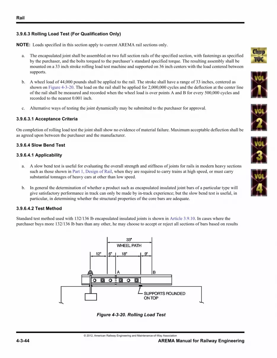
a. The encapsulated joint shall be assembled on two full section rails of the specified section, with fastenings as specified by the purchaser, and the bolts torqued to the purchaser’s standard specified torque. The resulting assembly shall be mounted on a 33 inch stroke rolling load test machine and supported on 36 inch centers with the load centered between supports.
b. A wheel load of 44,000 pounds shall be applied to the rail. The stroke shall have a range of 33 inches, centered as shown on Figure 4-3-20. The load on the rail shall be applied for 2,000,000 cycles and the deflection at the center line of the rail shall be measured and recorded when the wheel load is over points A and B for every 500,000 cycles and recorded to the nearest 0.001 inch.
c. Alternative ways of testing the joint dynamically may be submitted to the purchaser for approval.
3.9.6.3.1 Acceptance Criteria
On completion of rolling load test the joint shall show no evidence of material failure. Maximum acceptable deflection shall be as agreed upon between the purchaser and the manufacturer.
3.9.6.4 Slow Bend Test
3.9.6.4.1 Applicability
a. A slow bend test is useful for evaluating the overall strength and stiffness of joints for rails in modern heavy sections such as those shown in Part 1, Design of Rail, when they are required to carry trains at high speed, or must carry substantial tonnages of heavy cars at other than low speed.
b. In general the determination of whether a product such as encapsulated insulated joint bars of a particular type will give satisfactory performance in track can only be made by in-track experience; but the slow bend test is useful, in particular, in determining whether the structural properties of the core bars are adequate.
3.9.6.4.2 Test Method
Standard test method used with 132/136 lb encapsulated insulated joints is shown in Article 3.9.10. In cases where the purchaser buys more 132/136 lb bars than any other, he may choose to accept or reject all sections of bars based on results
Figure 4-3-20. Rolling Load Test

Joining of Rail
© 2012, American Railway Engineering and Maintenance-of-Way Association
AREMA Manual for Railway Engineering 4-3-45
1
3
4
from the 136 lb section. If the purchaser does not use 132/136 lb bars, acceptance/rejection criteria shall be as agreed between the supplier and purchaser.
3.9.6.4.3 Bending Strength
When tested in standard slow bend test machine using method shown in Paragraph 3.9.10, no damage or permanent deflection shall appear in 132/136 lb bars applied to full section 136 lb rail under 50 kips of vertical loading, or under 12 kips of horizontal loading.
3.9.6.4.4 Stiffness
At maximum vertical loading of 50 kips elastic deflection of the rail joint assembled as per Paragraph 3.9.6.4.3 shall not exceed 0.8 inch in the vertical direction. At maximum lateral loading of 12 kips, elastic deflection of the rail joint so assembled shall not exceed 0.7 inch in the lateral direction.
3.9.6.4.5 Causes for Rejection
Besides failure to meet any of the criteria given in Paragraph 3.9.6.4.3 and Paragraph 3.9.6.4.4, any breakage, cracking, splintering, bulging, delamination or visible permanent kinking of the joint, or any obvious kink or change of slope of the load/deflection curve will be considered evidence of damage and will be cause for rejection.
3.9.7 ACCEPTANCE (1996)
To be accepted, all encapsulated joints and components thereof must be shown to have fulfilled all requirements of this specification.
3.9.8 PACKAGING AND HANDLING (1996)
Packaging shall be done on the basis of one kit per carton, and shall be in accordance with the manufacturer’s standard packaging and handling methods, unless otherwise specified by the purchaser.
3.9.9 MARKING (1996)
Month and year of manufacture, name of manufacturer and rail section or sections fitted shall be marked on encapsulated insulated joint bars so it will remain during the life of the joint.
3.9.10 APPENDIX 1 – METHOD OF SLOW BEND TEST (1996)
a. Test shall be run on new joints of size and type prescribed by the manufacturer for use on 136 RE rail, using bolts specified by the manufacturer.
b. Joint(s) shall be assembled on two sections of new 136 RE rail to current AREMA specification, in accordance with manufacturer’s plans and directions. Bolts shall be tightened to torque prescribed by the manufacturer. Huck bolts or other connecting devices not capable of being re-tightened after application shall not be used with non-bonded encapsulated insulated rail joints.
c. Rail shall be supported on 72 inches span, with joint centered between supports, and central static loading applied. For vertical load tests, dial gages shall record vertical deflection at points located 3 inches on either side of the central loading point and on the center of the rail base. For lateral loading tests, load shall be applied at center of span through rail neutral axis, and deflections at rail head and at edge of rail base shall be measured by dial gages located 3 inches on either side of loading point.

Rail
© 2012, American Railway Engineering and Maintenance-of-Way Association
4-3-46 AREMA Manual for Railway Engineering
d. After taking initial dial gage readings, vertical load shall be applied in increments of 5 kips and deflections on the two dial gages shall be recorded for each increment. The average of the two deflection readings shall be plotted against load to produce a vertical load/deflection curve.
e. After taking initial readings, lateral load shall be applied in increments of one kip and deflections on the four dial gages shall be recorded for each load increment. The average of the four deflection readings shall be plotted against load to produce a lateral load/deflection curve.
f. Vertical and lateral load tests shall be conducted separately; i.e. vertical and lateral loads shall not be applied to the joint at the same time during the test.
g. Some nonlinearity of the load-deflection curve may be observed under the initial loading cycle, due to initial set of the plastic encapsulation material and bedding-in of the joint against the rail. When agreed between manufacturer and purchaser, retest may be made by cycling the joint up to full specified vertical and lateral load five times, retightening the bolts to specified torque and doing the prescribed vertical and lateral load-deflection tests over again.
SECTION 3.10 SPECIFICATION FOR THE QUALITY ASSURANCE OF ELECTRIC-FLASH BUTT WELDING OF RAIL1
— 1993 —
3.10.1 SCOPE (1994)
This specification covers mechanical properties, dimensional tolerances, and test procedures necessary for assuring quality of electric-flash butt welds of all rails manufactured to current AREMA specifications. The following is intended to cover initial process qualification and routine quality assurance requirements and procedures.
3.10.2 REQUIREMENTS (1994)
3.10.2.1 Bond Integrity
The bond between the two joining rail ends shall contain no more than one c inch diameter discontinuity.
3.10.2.2 Magnetic Particle Inspection
Magnetic particle inspection techniques when applied to rail welds shall meet the AREMA Specification for Fabrication of Continuous Welded Rail.
3.10.2.3 Hardness Criteria
a. No welds shall have hardness values greater than 400 BHN or 43 Rc.
b. Hardness within the weld shall be within ±30 BHN points or ±5 Rc of parent rails head hardness except at decarburized centerline and at the spherodized edge of the heat affected zone.
3.10.2.4 Dimensional Tolerances
All welds shall meet the AREMA Specification for Fabrication of Continuous Welded Rail.
1 References, Vol. 94 (1994), p. 58.