616.02 616-1 section 616 - irrigation system 1 2 3
TRANSCRIPT
616.02
616-1
SECTION 616 - IRRIGATION SYSTEM 1 2 3 616.01 Description. This section describes constructing permanent irrigation 4 system, including pipes, sprinkler heads, drip emitters, valves, automatic controllers, 5 remote control valves, power and control wiring, and related equipment and 6 materials. 7 8 616.02 Materials. 9 10
(A) PVC Pipe and Fittings. 11 12
(1) Pressure Irrigation Mains. 13 14
(a) For mains 2-1/2 inches and larger, PVC pipe shall be 15 Class 200, SDR 21, ASTM D 2241, with integral gasket bell 16 end. 17
18 (b) For mains 2 inches and smaller, PVC pipe shall be 19 Schedule 40, ASTM D 1785, with solvent-welded bell end. 20
21 (2) Laterals. Laterals shall be Class 200 PVC pipe, SDR 21, 22
ASTM D 2241, with solvent-welded bell end. 23 24
(3) Threaded Risers and Nipples. Risers and nipples shall be 25 Schedule 80 PVC. 26
27 (4) Other Risers and Fittings. Solvent-welded risers and fittings 28 shall be Schedule 40 PVC, Type I. 29
30 (5) Cement. Cement shall conform to ASTM D 2564, or shall be 31 product recommended by manufacturer. 32
33 (6) Sleeves. Sleeves shall be Schedule 80 PVC. 34
35 (7) Conduits. Conduits shall be Schedule 80 PVC, UL approved. 36
37 (B) Copper Pipe. Copper pipe for irrigation system shall conform to 38 Subsection 707.11(A) – Copper Service Pipe. 39
40 (C) Drip Tubes and Fittings. 41
42 (1) Polyethylene Pipe. Polyethylene pipe shall be PE 2305 or PE 43 2306 pipe, Class C, SDR 15, ASTM D 2447. 44
45 (2) Drip Emitters. Pressure-compensating drip emitters shall 46 include filtration system on inlet side, flexible black rubber diaphragm 47
616.02
616-2
to allow buildup of excess pressure within chamber for purging of 48 sediment and other debris not captured by disc filter, and hard plastic 49 diaphragm retainer with chamfered edges and recessed groove in 50 center running full length of diaphragm. 51
52 Emitters shall independently regulate discharge rates for 53 constant flow, with output pressure of 7 to 70 pounds per square inch 54 and coefficient of variability of 0.03. Discharge rate shall be 0.61 or 55 0.92 gallon per hour. Emitters shall be continuously self-cleaning and 56 utilize combination turbulent flow/reduced pressure compensation cell 57 mechanism and diaphragm for uniform discharge. 58
59 (3) Barbed Insert Fittings. Barbed fittings for insertion of emitters 60 into drip tubing shall be brown, molded plastic, and ultraviolet resisting. 61
62 (4) PVC Insert and Threaded Fittings. Inserts and threaded 63 fittings shall be unplasticized PVC I or PVC II. 64
65 (5) Line Flushing Valve. Line flushing valve shall be black, non-66 serviceable, molded plastic. Valve shall run automatically during initial 67 system pressure build up and shall discharge at rate of one gallon 68 water for each 15 gallons per minute of demand. Working pressure 69 shall be minimum of 4 pounds per square inch and maximum of 25 70 pounds per square inch. 71
72 (6) Pressure Regulating Valve. Pressure regulating valve shall be 73 black, molded plastic, spring-operated, piston-type valve with 74 regulation unit that can be serviced without having to remove valve. 75
76 (7) Disc Filter. Filter shall be black, molded plastic, disc-type filter. 77 Filtration mesh shall be color-coded. 78
79 (8) Air and Vacuum Relief Valve. Air and vacuum relief valve 80 shall be gray plastic, with internal sliding poppet. 81
82 (9) Stainless Steel Clamp. Stainless steel clamp shall be 304 AISI 83 ear-type. 84
85 (D) Sprinkler Heads. Sprinkler heads shall conform to following: 86
87 (1) Lawn type sprinkler heads, shrubbery heads, and bubbler 88 heads shall have plastic or brass bodies and adjustable spray. 89
90 (2) Lawn pop-up sprinkler heads shall have plastic or brass bodies, 91 machined plastic or brass internal parts, and adjustable spray. Head 92 shall include pop-up feature that returns head freely after operating on 93 30-degree incline. 94
616.02
616-3
95 (3) Jet sprinkler heads shall be plastic, brass, bronze, stainless 96 steel, or combination of the metals. Nozzles shall be plastic or brass, 97 precision-machined, removable, and interchangeable. Arms or levers 98 shall be brass, bronze, or anodized aluminum. Part-circle heads shall 99 have positive locking, adjustable arc stops. Impact or gear driven 100 sprinklers shall work smoothly under specified operating pressure 101 without stalling. 102
103 (4) Rotary pop-up sprinklers shall have same construction as jet 104 sprinklers. Casing shall be plastic, brass, bronze, cast-iron, or 105 aluminum, with non-corrosive coating. Cover shall be brass, bronze, 106 or aluminum. Part-circle heads shall have positive locking, adjustable 107 arc stops. Sprinklers shall have internal mechanisms that are 108 removable from top. Sprinklers shall operate smoothly under 109 specified operating pressure without stalling. 110
111 (5) If specified, part-circle jet and rotary pop-up sprinklers shall 112 have anti-splash device. 113
114 (6) Nozzle sprinkler heads shall be plastic or brass. 115
116 (E) Springs for Sprinkler Risers. Springs for sprinkler risers shall be 117 compression-type manufactured from 0.187-inch diameter OTMB spring wire 118 or similar. Coil shall have inside diameter of 0.900 to 0.920 inch, and shall be 119 wound at pitch of 0.475 inch. Spring shall be squared at ends only. 120
121 (F) Valves. 122
123 (1) Quick Coupling Valve. Quick coupling valve shall have two-124 piece body, self-closing cap, and service rating of 150 pounds per 125 square inch. Quick coupling valve shall be brass or bronze, except for 126 cap. Key or coupler for valve shall be brass, bronze, stainless steel, 127 or combination of the metals. 128
129 (2) Garden Valve. Garden valve shall be straight-nose, brass, or 130 bronze valve with replaceable compression discs. Handles shall be 131 brass, bronze, or steel. 132
133 (3) Manual Control Valve. Manual control valve shall be brass or 134 bronze bodied, straight or angle pattern globe valve with replaceable 135 compression discs. Handles shall be brass, bronze, or steel. Manual 136 control valve shall be same size as pipe served and shall withstand 137 working pressure of 150 pounds per square inch. 138
139 (4) Gate Valve. Gate valve shall be bronze or iron bodied, bronze 140 trimmed with internally threaded rising or non-rising stem, and of 141
616.02
616-4
flanged, threaded, or ring type. Gate valve shall have bronze, brass, 142 or steel handles when valve is 3 inches or smaller. Larger valves shall 143 have two square operating nuts. Gate valve shall withstand cold 144 water working pressure of 150 pounds per square inch. 145
146 (5) Valve Assembly Unit. 147
148 (a) Control Valve. Control valve shall conform to 149 Subsection 616.02(F)(3) – Manual Control Valve. 150
151 (b) Pressure Regulator. Pressure regulator shall conform 152 to Subsection 616.02(G) – Pressure Regulator. 153
154 (c) Filter. Filter shall have reinforced polypropylene plastic 155 body; disposable filter cartridge; cylindrical shape, 156 approximately 5 inches in diameter and 12 inches long; and 157 3/4-inch NPT connections. Filter shall withstand working 158 pressure of 150 pounds per square inch. Filter cartridge shall 159 have 50-micron rating, withstand working pressure of 70 160 pounds per square inch, and operate at maximum temperature 161 of 210 degrees F. 162
163 (d) Pressure Gage. Pressure gage shall have case and 164 window of polycarbonate resin. Pressure gage shall be 1-1/2 165 inches in diameter, calibrated to read from 0 to 60 pounds per 166 square inch in two-pound increments, and equipped with black 167 aluminum pointer. Each valve assembly unit shall have two 168 pressure gages. 169
170 (e) Valve Box. Valve box shall conform to Subsection 171 616.02(I) – Valve Box and Cover. 172
173 (6) Remote Control Valve. Electric control valve in specified size 174 shall have brass or bronze body, straight or angle pattern, and 175 solenoid that operates on 24 to 30 volts of alternating current. 176 Minimum working pressure shall be 150 pounds per square inch. 177 Remote control valve shall have integrated union in discharge side, 178 shall be serviceable from top, and shall have automatic closing time 179 greater than five seconds. Manufacturer of remote control valve shall 180 be same as manufacturer of electric controller or master-satellite 181 controller. 182
183 (7) Check Valve. Check valve shall be diaphragm type, globe 184 patterned, hydraulically operated, with body and cover of cast iron, 185 and with internal parts of brass or bronze. Pipe connection shall be 186 screw or flange type. Minimum working pressure shall be 150 pounds 187 per square inch. 188
616.02
616-5
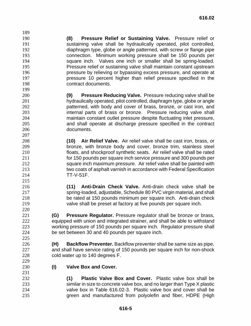
189 (8) Pressure Relief or Sustaining Valve. Pressure relief or 190 sustaining valve shall be hydraulically operated, pilot controlled, 191 diaphragm type, globe or angle patterned, with screw or flange pipe 192 connection. Minimum working pressure shall be 150 pounds per 193 square inch. Valves one inch or smaller shall be spring-loaded. 194 Pressure relief or sustaining valve shall maintain constant upstream 195 pressure by relieving or bypassing excess pressure, and operate at 196 pressure 10 percent higher than relief pressure specified in the 197 contract documents. 198
199 (9) Pressure Reducing Valve. Pressure reducing valve shall be 200 hydraulically operated, pilot controlled, diaphragm type, globe or angle 201 patterned, with body and cover of brass, bronze, or cast iron, and 202 internal parts of brass or bronze. Pressure reducing valve shall 203 maintain constant outlet pressure despite fluctuating inlet pressure, 204 and shall operate at discharge pressure specified in the contract 205 documents. 206
207 (10) Air Relief Valve. Air relief valve shall be cast iron, brass, or 208 bronze, with bronze body and cover, bronze trim, stainless steel 209 floats, and shockproof synthetic seats. Air relief valve shall be rated 210 for 150 pounds per square inch service pressure and 300 pounds per 211 square inch maximum pressure. Air relief valve shall be painted with 212 two coats of asphalt varnish in accordance with Federal Specification 213 TT-V-51F. 214
215 (11) Anti-Drain Check Valve. Anti-drain check valve shall be 216 spring-loaded, adjustable, Schedule 80 PVC virgin material, and shall 217 be rated at 150 pounds minimum per square inch. Anti-drain check 218 valve shall be preset at factory at five pounds per square inch. 219
220 (G) Pressure Regulator. Pressure regulator shall be bronze or brass, 221 equipped with union and integrated strainer, and shall be able to withstand 222 working pressure of 150 pounds per square inch. Regulator pressure shall 223 be set between 30 and 40 pounds per square inch. 224
225 (H) Backflow Preventer. Backflow preventer shall be same size as pipe, 226 and shall have service rating of 150 pounds per square inch for non-shock 227 cold water up to 140 degrees F. 228
229 (I) Valve Box and Cover. 230 231
(1) Plastic Valve Box and Cover. Plastic valve box shall be 232 similar in size to concrete valve box, and no larger than Type X plastic 233 valve box in Table 616.02-3. Plastic valve box and cover shall be 234 green and manufactured from polyolefin and fiber, HDPE (High 235
616.02
616-6
Density Polyethylene), or ABS (Acrylonitrile-Butadiene-Styrene). 236 Valve box cover shall be marked with “IRRIGATION BOX,” 237 “IRRIGATION CONTROL VALVE,” or “CONTROL VALVE.” 238
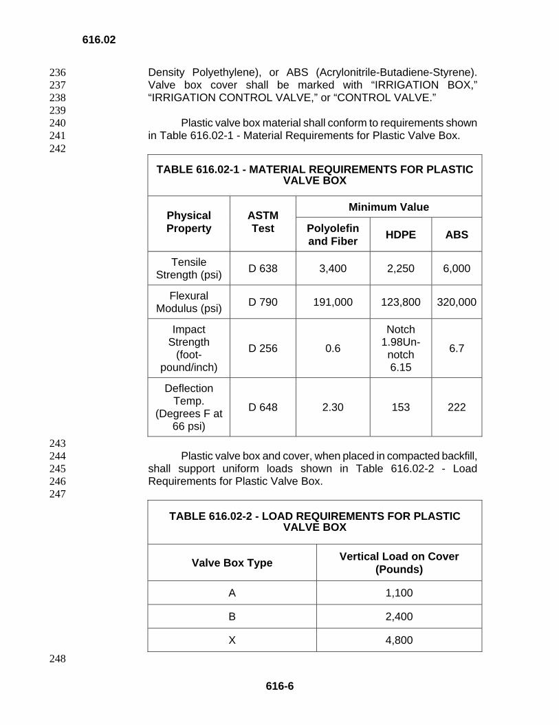
239 Plastic valve box material shall conform to requirements shown 240 in Table 616.02-1 - Material Requirements for Plastic Valve Box. 241
242
TABLE 616.02-1 - MATERIAL REQUIREMENTS FOR PLASTIC VALVE BOX
Minimum Value Physical Property
ASTM Test Polyolefin
and Fiber HDPE ABS
Tensile Strength (psi) D 638 3,400 2,250 6,000
Flexural Modulus (psi) D 790 191,000 123,800 320,000
Impact Strength
(foot-pound/inch)
D 256 0.6
Notch 1.98Un-notch 6.15
6.7
Deflection Temp.
(Degrees F at 66 psi)
D 648 2.30 153 222
243 Plastic valve box and cover, when placed in compacted backfill, 244 shall support uniform loads shown in Table 616.02-2 - Load 245 Requirements for Plastic Valve Box. 246
247
TABLE 616.02-2 - LOAD REQUIREMENTS FOR PLASTIC VALVE BOX
Valve Box Type Vertical Load on Cover (Pounds)
A 1,100
B 2,400
X 4,800
248
616.02
616-7
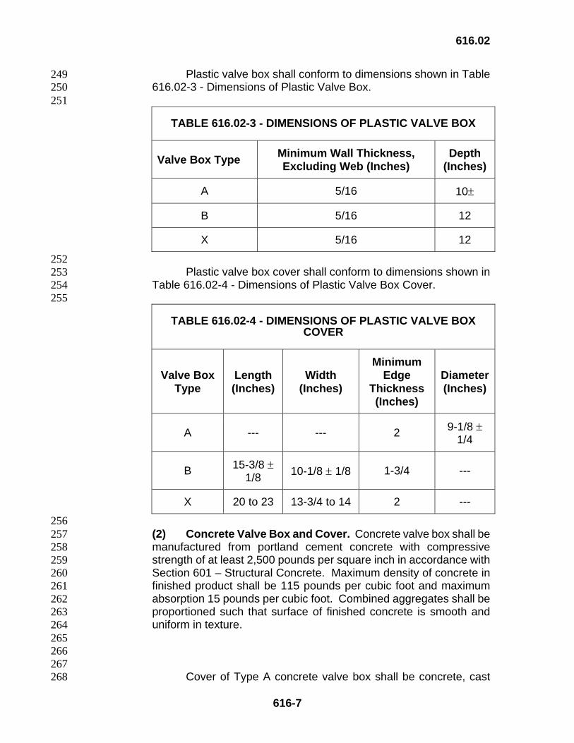
Plastic valve box shall conform to dimensions shown in Table 249 616.02-3 - Dimensions of Plastic Valve Box. 250
251
TABLE 616.02-3 - DIMENSIONS OF PLASTIC VALVE BOX
Valve Box Type Minimum Wall Thickness, Excluding Web (Inches)
Depth (Inches)
A 5/16 10±
B 5/16 12
X 5/16 12
252 Plastic valve box cover shall conform to dimensions shown in 253 Table 616.02-4 - Dimensions of Plastic Valve Box Cover. 254
255
TABLE 616.02-4 - DIMENSIONS OF PLASTIC VALVE BOX COVER
Valve Box Type
Length (Inches)
Width (Inches)
Minimum Edge
Thickness (Inches)
Diameter(Inches)
A --- --- 2 9-1/8 ± 1/4
B 15-3/8 ± 1/8 10-1/8 ± 1/8 1-3/4 ---
X 20 to 23 13-3/4 to 14 2 ---
256 (2) Concrete Valve Box and Cover. Concrete valve box shall be 257 manufactured from portland cement concrete with compressive 258 strength of at least 2,500 pounds per square inch in accordance with 259 Section 601 – Structural Concrete. Maximum density of concrete in 260 finished product shall be 115 pounds per cubic foot and maximum 261 absorption 15 pounds per cubic foot. Combined aggregates shall be 262 proportioned such that surface of finished concrete is smooth and 263 uniform in texture. 264
265 266 267
Cover of Type A concrete valve box shall be concrete, cast 268
616.02
616-8
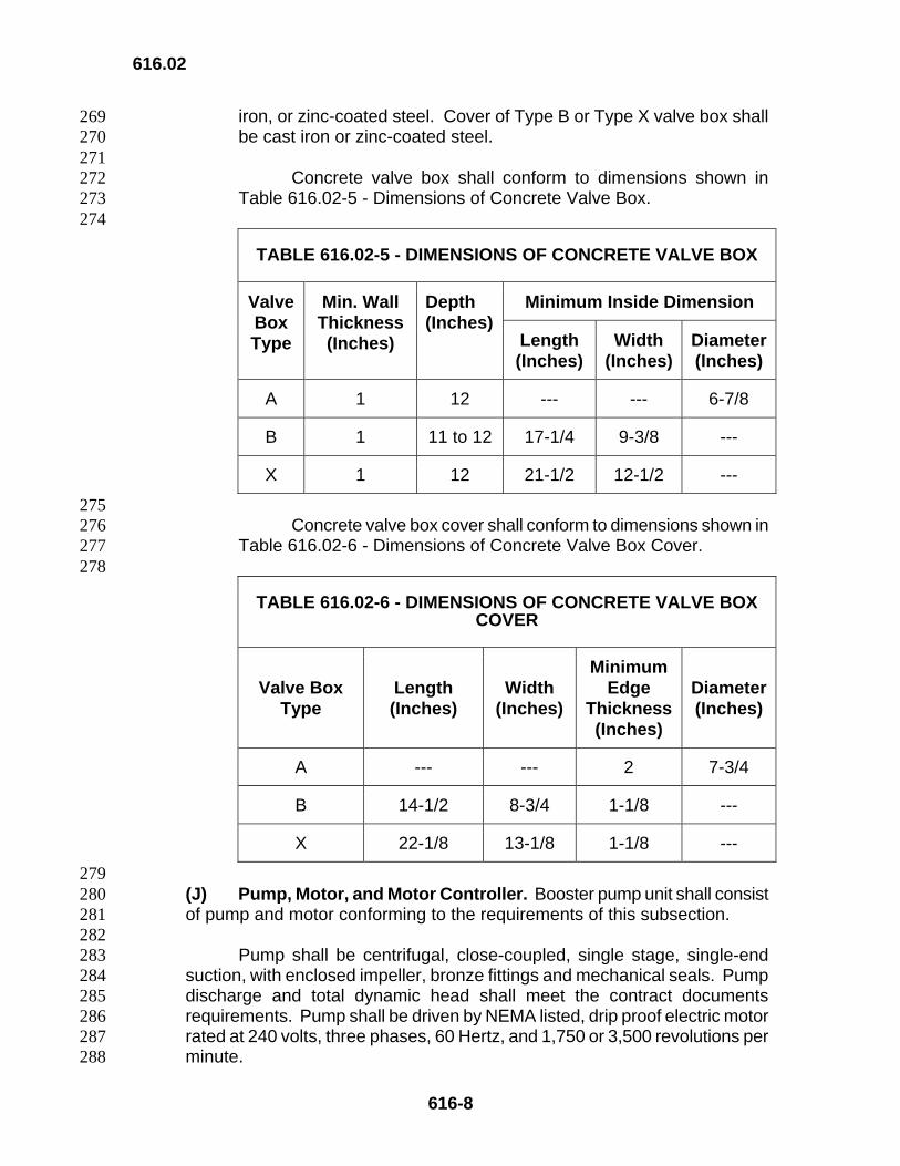
iron, or zinc-coated steel. Cover of Type B or Type X valve box shall 269 be cast iron or zinc-coated steel. 270
271 Concrete valve box shall conform to dimensions shown in 272 Table 616.02-5 - Dimensions of Concrete Valve Box. 273
274
TABLE 616.02-5 - DIMENSIONS OF CONCRETE VALVE BOX
Minimum Inside Dimension Valve Box Type
Min. Wall Thickness (Inches)
Depth (Inches)
Length (Inches)
Width (Inches)
Diameter (Inches)
A 1 12 --- --- 6-7/8
B 1 11 to 12 17-1/4 9-3/8 ---
X 1 12 21-1/2 12-1/2 ---
275 Concrete valve box cover shall conform to dimensions shown in 276 Table 616.02-6 - Dimensions of Concrete Valve Box Cover. 277
278
TABLE 616.02-6 - DIMENSIONS OF CONCRETE VALVE BOX COVER
Valve Box Type
Length (Inches)
Width (Inches)
Minimum Edge
Thickness(Inches)
Diameter (Inches)
A --- --- 2 7-3/4
B 14-1/2 8-3/4 1-1/8 ---
X 22-1/8 13-1/8 1-1/8 ---
279 (J) Pump, Motor, and Motor Controller. Booster pump unit shall consist 280 of pump and motor conforming to the requirements of this subsection. 281
282 Pump shall be centrifugal, close-coupled, single stage, single-end 283 suction, with enclosed impeller, bronze fittings and mechanical seals. Pump 284 discharge and total dynamic head shall meet the contract documents 285 requirements. Pump shall be driven by NEMA listed, drip proof electric motor 286 rated at 240 volts, three phases, 60 Hertz, and 1,750 or 3,500 revolutions per 287 minute. 288
616.02
616-9
289 Each motor shall have appropriately sized, full-voltage magnetic 290 starter with thermal overload and short circuit protection for each phase, in 291 combination with fused safety switch, in accordance with Subsection 292 616.02(P)(4) – Safety Switches, in NEMA 1 enclosure with hinged cover. 293 Overload reset and control operator shall be covered. Motor shall conform to 294 NEMA Standard MG 1, and controls and starters to NEMA Standard ICS. 295 Each starter shall include spare set of fuses. 296
297 (K) Switching Tensiometer. 298
299 (1) Bourdon-Tube Type. Switching tensiometer shall include 300 vacuum gage and airtight, water-filled, rigid, clear plastic tube with 301 porous ceramic tip at bottom to afford high flow rate for sensitive 302 response. Vacuum gage shall have positive ON/OFF switch 303 adjustable from 0 to 100 centibars. Electrical capacity of unit shall be 304 24 volts, alternating or direct current, 1/2 ampere, 10 watts. Wire 305 leads shall connect switch to controller or solenoid valve. 306
307 (2) Solid-State Type. Unit shall operate by heat diffusion with one 308 solid-state tensiometer for each remote control valve. Tensiometer 309 shall be equipped with preset stress value of 24 centibars and 310 override switch at top. Electrical capacity shall be 15 watts, 311 alternating current. Tensiometers shall be connected in series with 312 each remote control valve cable. 313
314 (L) Rain Sensor Switch. Sensor switch to prevent watering during 315 periods of rain shall be compatible with irrigation control system and shall not 316 interfere with watering program. 317
318 (M) Automatic Controller. Automatic controller shall have multiple 319 program capabilities, 24-hour clock, 12-hour watering duration, and station 320 timing programmable from 0 to 2 hours in 1-minute increments, and 2 to 12 321 hours in 10-minute increments. 322
323 (1) Controller equipment shall include heavy-duty surge protection, 324 UL listed and CSA and CE approved, for input and output. Controller 325 shall operate on minimum of 115 volts, single-phase, alternating 326 current; or minimum of 24 volts, single-phase, alternating current, with 327 external 115 to 24 volt step-down transformer. Backup fuse shall be 328 included for supply overload. Backup battery shall be provided for 329 programming under battery power or maintaining irrigation schedule 330 during power outage. 331
332 333
616.02
616-10
(2) Controllers shall be wall-mounted or pedestal-mounted, and 333 shall be equipped with moisture sensor and automatic rain shut-off 334 switch. 335
336 (3) Controller shall be enclosed in accordance with manufacturer’s 337 instructions and Subsection 616.02(N) – Controller Enclosure. 338
339 (N) Controller Enclosure. Enclosure for controller shall be vandal and 340 weather resistant, lockable, and constructed entirely of stainless steel. 341
342 (1) Main housing shall be equipped with stainless steel backboard 343 for mounting of controller. Backboard shall include four removable 344 stainless steel bolts. Side panels shall include louvers on top and 345 bottom for ventilation. 346
347 (2) Adequate storage space shall be provided along inside of door 348 for plans, operating instructions, and program schedules. Door shall 349 be equipped with continuous stainless steel piano hinge at one edge 350 and three-point locking mechanism at other edge. Handle for locking 351 mechanism shall be located at base of door and shall be concealed 352 within door. Padlock and two keys shall be provided for enclosure. 353
354 (O) Master-Satellite Control System. Master controller shall include at 355 least two completely independent stations, operate on 120 volts of single-356 phase alternating current, and supply 30 volts of continuous current to 357 satellite controllers. 358
359 Master controller shall be fully automatic and capable of providing 360 complete 14-day minimum irrigation program. Controller shall be equipped 361 with 24-hour clock with minimum incremental starts of one hour, circuit 362 breaker protection, 30-volt transformer, and MANUAL/OFF/AUTOMATIC 363 control switches. Time and clock set adjustments shall not require insertion 364 or removal of pins. Captive pins are acceptable. 365
366 (P) Electrical Requirements. Electrical equipment and materials shall 367 conform to NEMA Standards. Electrical work shall be done in accordance 368 with the National Electrical Code, General Order No. 6 of the Hawaii Public 369 Utilities Agreement, local power company rules, and local ordinances as 370 applicable to the Project. 371
372 (1) Cables, Conductors, and Wire for Irrigation System. 373
374 (a) General. Wire and cable shall be single-conductor 375 copper. Conductor shall be annealed, uncoated wire 376 conforming to ASTM B 3. Conductors No. 6 and larger shall be 377 stranded wire, Class B, conforming to ASTM B 8. Bare 378 conductors shall be soft-drawn wire. 379
616.02
616-11
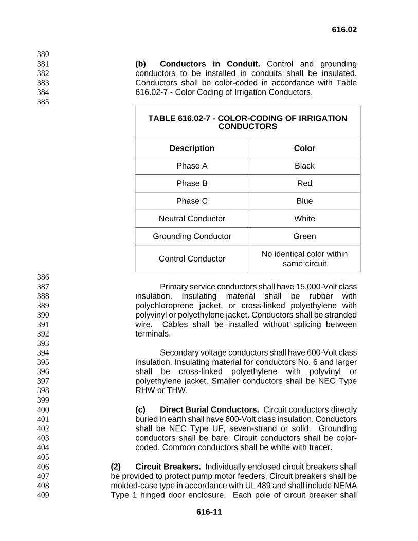
380 (b) Conductors in Conduit. Control and grounding 381 conductors to be installed in conduits shall be insulated. 382 Conductors shall be color-coded in accordance with Table 383 616.02-7 - Color Coding of Irrigation Conductors. 384
385
TABLE 616.02-7 - COLOR-CODING OF IRRIGATION CONDUCTORS
Description Color
Phase A Black
Phase B Red
Phase C Blue
Neutral Conductor White
Grounding Conductor Green
Control Conductor No identical color within same circuit
386 Primary service conductors shall have 15,000-Volt class 387 insulation. Insulating material shall be rubber with 388 polychloroprene jacket, or cross-linked polyethylene with 389 polyvinyl or polyethylene jacket. Conductors shall be stranded 390 wire. Cables shall be installed without splicing between 391 terminals. 392
393 Secondary voltage conductors shall have 600-Volt class 394 insulation. Insulating material for conductors No. 6 and larger 395 shall be cross-linked polyethylene with polyvinyl or 396 polyethylene jacket. Smaller conductors shall be NEC Type 397 RHW or THW. 398
399 (c) Direct Burial Conductors. Circuit conductors directly 400 buried in earth shall have 600-Volt class insulation. Conductors 401 shall be NEC Type UF, seven-strand or solid. Grounding 402 conductors shall be bare. Circuit conductors shall be color-403 coded. Common conductors shall be white with tracer. 404
405 (2) Circuit Breakers. Individually enclosed circuit breakers shall 406 be provided to protect pump motor feeders. Circuit breakers shall be 407 molded-case type in accordance with UL 489 and shall include NEMA 408 Type 1 hinged door enclosure. Each pole of circuit breaker shall 409
616.02
616-12
provide inverse time delay overload and instantaneous short circuit 410 protection. Terminals shall be pressure type, sized for easy 411 connection of wire. Breakers shall be lockable from either position, 412 three-pole, 480 volts, with interrupting rating of 14,000 symmetrical 413 amperes at rated voltage. Specifications for continuous current shall 414 meet the requirements of the contract documents. 415
416 Individually enclosed circuit breakers shall be provided in 417 accordance with Subsection 602.02(P)(3) – Panel Boards, when use 418 is other than at pump motor feeders. 419
420 (3) Panel Boards. Panel boards shall conform to UL 67 and shall 421 include NEMA Type 1 enclosure. Panel board circuit breakers shall 422 conform to UL 489. Voltage, interrupting symmetrical ampere rating 423 at rated voltage, and continuous current rating of circuit breaker shall 424 be as specified in the contract documents. Panel board shall be 425 equipped with insulated, groundable neutral bus. 426
427 (4) Safety Switches. Safety switches used in combination with 428 motor starters shall conform to UL 98 and shall be heavy duty, three-429 pole, 240 volts, sized and equipped with fuses appropriate to motor 430 served. 431
432 (5) Snap Switches. Snap switches used for on/off power control 433 to circuits 120 volts and below shall be single-pole, 20 amperes, and 434 shall conform to UL 20. Switches shall be mounted in enclosure. 435
436 (6) Meter and Service Equipment Cabinets. Cabinets shall be 437 welded steel, sized for equipment housed, and shall be rain-tight 438 equal to NEMA 3R. Door shall be tamper-proof, hinged and lockable. 439 Backboard shall be exterior grade plywood, finished on one side, 440 treated with fungus and insect repellant, and affixed to cabinet in shop 441 with two-part epoxy cement and bolts. Entire cabinet shall be painted 442 in shop in accordance with Subsection 708.03 – Dark Green Enamel 443 Paint. 444
445 (7) Transformers. Transformer shall be dry, of rating in the 446 contract documents, and totally enclosed in weatherproof case with 447 integral wiring compartment. Transformer shall provide voltage step-448 down from 120 volts to 24 volts, shall conform to NEMA Standard ST 449 1, and shall be equipped with standard primary voltage taps in 450 conformance with NEMA. Insulation shall be rated for 239 degrees F 451 rise, Class F. 452
453 (8) Meter Sockets. Meter sockets for self-contained meters shall 454 be seven-jawed and shall be acceptable to serving electric utility 455 company. 456
616.03
616-13
457 (9) Ground Rods. Ground rods shall be rolled to round shape 458 from copper-encased steel made by molten welding process or 459 electro-formed molecular bonding. Copper surface of ground rod shall 460 be hard, clean, smooth, continuous, and at least 0.013 inch thick. 461 Ground rods shall be diameter and length specified in the contract 462 documents. 463
464 (10) Receptacles. Receptacles shall be duplex, 15 amperes, and 465 125 volts in conformance with NEMA Configuration 5-15R. 466 Receptacles shall be mounted in sheet metal box with cover in 467 conformance with UL Standard 514. 468
469 (Q) Concrete. Concrete for jackets and reaction blocks shall be Class B 470 and shall conform to Section 601 – Structural Concrete. 471
472 (R) Miscellaneous Materials. 473
474 Trench Backfill Material 703.21 475
476 Zinc-coated Pipe and Fittings 707.10 477
478 Copper Service Pipe and Appurtenances 707.11 479
480 Dark Green Enamel Paint 708.03 481
482 Concrete Pull Box 712.06(B) 483
484 Frame and Cover 712.07(A) 485
486 Cullet Materials for Drainage Systems 717.04 487
488 (S) Asbestos. Materials containing asbestos shall not be used. Asbestos 489 that has already been installed shall be removed and replaced at no cost to 490 the State. 491
492 616.03 Construction. 493 494
(A) General. Furnish materials and equipment for permanent irrigation 495 system that are new and obtained from named and accepted manufacturers. 496 Materials and equipment for temporary irrigation system do not have to be 497 new, but shall be from named and accepted manufacturers. The Engineer 498 will inspect and test materials. 499
500 (B) Responsibility of the Contractor. 501
502 (1) Obtain and pay costs of necessary permits and certificates. 503
616.03
616-14
504 (2) Repair damage, caused by the Contractors operation, to known 505 underground utilities or other improvements. 506
507 (3) Exercise caution when working near existing improvements. 508 Install barriers to protect against injury or defacement of 509 improvements. 510
511 (4) Repair damage from leaks caused by faulty materials or 512 workmanship during installation of irrigation system and during plant 513 establishment period. Restore area to original condition. 514
515 (5) Provide one-year material warranty for repairs and 516 modifications to permanent irrigation systems, commencing with date 517 of final acceptance of permanent system. 518 519 (6) Provide repair and maintenance of temporary irrigation system 520 from installation to removal. 521
522 (C) Pre-Construction Submittals. 523
524 (1) Within 10 days after award of the Contract, submit following: 525
526 (a) Construction Schedules. Provide six copies of 527 separate schedules for construction of permanent and 528 temporary irrigation systems. Include estimated completion 529 dates, number of working days, and special coordination 530 requirements. 531
532 (b) Equipment Lists. Provide six copies of separate 533 equipment lists for permanent and temporary irrigation 534 systems. Name manufacturer and provide catalog number. 535 Include pipes, sprinkler heads, emitters, valves, irrigation 536 control equipment, and other materials that will be installed. 537
538 (2) Shop Drawings. Within 30 days after award of the Contract, 539 submit for the Engineer’s acceptance six copies of detailed scale 540 drawings and wiring diagrams for permanent and temporary irrigation 541 systems. Note proposed deviations from the Contract. Include 542 samples of materials, if required by the Contract. 543
544 (D) Post-Construction Submittals. Before final acceptance of 545 landscape plantings and end of plant establishment period, submit following 546 for the Engineer’s acceptance: 547
548 (1) Service Manual. Provide six individually bound copies of 549 service manual for permanent irrigation system in three-ring, hard 550 cover binders. Include following: 551
552
616.03
616-15
(a) Index sheet with the Contractor’s name, address, and 553 telephone number. 554
555 (b) Equipment and material warranties and certificates. 556
557 (c) Equipment and material list with names, addresses, and 558 telephone numbers of local or nearest manufacturers’ 559 representatives. 560
561 (d) Complete as-built irrigation drawings and diagrams. 562
563 (e) Controller charts. 564 565
(f) Complete, easy-to-understand instructions for operating 566 and maintaining irrigation system, in sufficient detail for use by 567 the State’s maintenance forces. 568
569 (2) As-Built Drawings. Before backfilling, record as-built changes 570 to irrigation system in red on working set of prints of the plans. Include 571 accurate data showing locations of irrigation mains, connection points, 572 valves, control wiring, electrical boxes, controllers, sprinkler heads, 573 emitters, and capped ends for future extension. Reference changes to 574 permanent improvements such as sidewalks, curbs, and monuments. 575
576 (a) Keep working set of marked-up prints at the Project site 577 and update data daily. 578
579 (b) When construction of irrigation system is completed, 580 furnish reproducible full-size tracings with transcribed as-built 581 data. Submit working set and complete set of tracings 582 indicating as-built condition of irrigation system to the Engineer. 583
584 (3) Keys. Furnish the following: 585
586 (a) Two long-shank keys or wrenches for adjusting flow rate 587 of manual control valves. 588
589 (b) Two valve keys for 4-inch and larger gate valves. 590
591 (c) Six keys for irrigation controller. 592
593 (d) Six keys for controller enclosure. 594
595 (E) Workmanship. Conform to laws, codes, and regulations applicable to 596 the work. Provide inspections and permits required by governmental 597 authorities. 598
599
616.03
616-16
599 600 (F) Layout. 601
602 (1) Check grades to affirm that work can proceed safely. Keep 603 within specified depths of construction. Take special note that 604 dimensions in irrigation layout are horizontal and will differ from 605 measurements taken along slopes. 606
607 (2) If site conditions do not allow pipes, valves, or sprinkler heads 608 to be located as drawn, consult with the Engineer immediately for joint 609 determination of revised location. Changes made without the 610 Engineer’s knowledge may not be accepted for payment. 611
612 (3) Do not construct in accordance with the contract documents if 613 there are obvious discrepancies or differences. Bring these matters to 614 the Engineer’s attention and wait for direction before proceeding. The 615 Engineer will hold the Contractor responsible for unauthorized work. 616
617 (4) If there is conflict between contract documents and the conflict 618 has not been resolved before start of construction, obtain direction 619 from the Engineer before proceeding. 620
621 (G) Utility Connections. 622
623 (1) Water. Provide water service connection in accordance with 624 requirements of governing agency. Pay all related costs. 625
626 (2) Electric. Arrange with local power company for electric service 627 connection to irrigation controllers. Pay all related costs. 628
629 (H) Excavation and Backfill. 630
631 (1) Provide trench excavation to install pipes. . 632
633 (2) Excavate trench to width necessary to install pipe; provide 634 additional width for joints. Excavate to depth shown in the contract 635 documents. If contract documents do not specify depth of excavation, 636 provide minimum cover to finished grade as follows: 637
638 (a) 4 inches for drip irrigation tubing. 639
640 (b) 18 inches for irrigation main. 641
642 (c) 10 inches for irrigation lateral. 643
644 645
616.03
616-17
(d) 24 inches for sleeve or conduit under landscape 645 pavement. 646
647 (e) 36 inches for sleeve or conduit under roadway 648 pavement. 649 650 Rototill before installing drip irrigation system. 651
652 (3) Remove rocks larger than 2 inches, roots, and other 653 obstructions completely, or cut obstruction to width of trench and six 654 inches below pipe. Dispose of debris in accordance with Section 202 655 – Removal of Structures and Obstructions. Backfill over-excavation 656 and tamp carefully to provide firm and smooth foundation for pipe. 657
658 (4) Wherever possible, place irrigation mains and other irrigation 659 lines in same trench. Provide specified minimum clearance between 660 pipes. 661
662 (5) Install barricades or temporary lighting at excavations if 663 necessary for public safety. 664
665 (I) Assembling Pipe. 666
667 (1) Assemble pipe at point of connection in accordance with 668 manufacturer’s instructions. Adjust for site conditions and weather. 669
670 (2) Install irrigation pipe under existing pavement in accordance 671 with requirements of the contract documents. 672
673 (3) Plastic Threaded Joints. Provide factory-molded joints only. 674 Field threading of plastic pipe or fittings will not be allowed. Make 675 plastic to metal connections using female plastic threads. 676
677 (4) Make metal-threaded joints using proper tools and joint 678 compounds. Do not caulk. No more than three full threads shall be 679 visible when joint is finished. Make field cuts only with permission of 680 the Engineer. 681
682 (5) Make flanged connections using accepted gaskets and bolt 683 sets. Tighten assembly bolts to proper torque. 684
685 (6) For bell-jointed pipe, provide concrete thrust blocks at irrigation 686 main for pressure resistance. Follow standard plumbing practice in 687 constructing thrust block. 688
689 (7) Install removable, non-decaying plugs at ends of pipe sleeves 690 and control wire conduits. 691
692 693
616.03
616-18
(J) Laying Pipe and Emitters. 693 694
(1) Refer to landscape plans for routing of irrigation lines relative to 695 plantings. 696
697 (2) Install parallel pipes in same trench and to same depth, with 698 minimum horizontal separation of two inches. Do not permit parallel 699 pipes to cross. 700
701 (3) Lay pipe flat on bottom of trench, and accurate as to specified 702 alignment and grade. Do not place pipe on soft or unstable soil, or 703 when water is present. Remove undesirable soil and replace with 704 trench backfill material. De-water trench and allow backfill to dry. 705
706 (4) Except at connections, install bell-jointed pipe with bell end 707 facing direction of laying. 708
709 (5) Provide minimum vertical separation of two inches at pipe 710 crossings. Direct contact of pipe with other pipes or structures will not 711 be allowed. 712
713 (6) Install drip tubes and fittings in accordance with manufacturer’s 714 instructions. 715
716 (7) Flush pipes thoroughly to remove debris and other foreign 717 matter. 718
719 (8) Complete tests and repairs before paving over pipe. 720
721 (9) Inspect completed pipe sections for leaks at joints and fittings. 722 Repair or replace pipe, if necessary, before backfilling. 723
724 (K) Flushing. Thoroughly flush pipe before installing valves, filters, 725 sprinkler heads, and emitters. After flushing, partial backfill of pipe is 726 allowed. Keep butt joints, fittings, and connections visible and free of 727 obstructions. 728
729 (L) Installing Equipment. 730
731 (1) Valves. 732
733 (a) Thoroughly flush irrigation main before installing valves. 734
735 (b) Install valves plumb when connected directly to irrigation 736 main, with sufficient clearance for operation and service. 737 Locate valve no farther than 12 inches from irrigation main. 738
739 (c) Install gate valves before installing manual or remote 740 control valve manifolds or quick coupler valves. 741
616.03
616-19
742 (d) Install manual control valves and gate valves as 743 specified. Maintain accessibility to valves. 744
745 (e) Locate valve boxes so that outer edges are no closer 746 than five feet to roadway pavement. 747
748 (f) Install control valves in valve boxes. Provide extension if 749 necessary to keep soil clear of valve and solenoid. Provide 750 individual box for each valve. Set valve box parallel with edge 751 of sidewalk or roadway, and top of box flush with finished 752 grade. 753
754 (g) Install remote control valve in location central to 755 sprinkler or drip system. Adjust flow control for optimal 756 efficiency. 757
758 (2) Valve Boxes. 759
760 (a) Install valve box on three-inch thick gravel bed for 761 drainage. Keep dirt and debris out of box. 762
763 (b) Label valve box permanently with valve number and 764 controller letter in manner shown in the contract documents or 765 accepted by the Engineer. 766
767 (3) Automatic Control Wiring. 768
769 (a) Provide conduits for control wires at pavement crossings 770 and wherever wires require protection from damage. Place 771 invert of conduit minimum of 24 inches beneath surface of 772 landscape pavements and 36 inches beneath surface of 773 roadway pavements. 774
775 (b) Run wires in irrigation pipe trenches wherever possible. 776 Bundle wires with wrapping tape at 10-foot intervals. Provide 777 slack in wraps to allow wires to expand and contract. Place 778 wiring for permanent irrigation system minimum of 18 inches 779 beneath surface of planted areas. 780
781 (c) For control and ground wires, loop at least two feet of 782 extra wire at each valve box, splice, change of direction, 500 783 feet of straight run, and at controller. Coil extra wire neatly 784 within valve box. 785
786 (d) Use connectors as shown in the contract documents or 787 acceptable to the Engineer. 788
789 (e) Splice wires only if run is greater than 2,500 feet. Make 790
616.03
616-20
splices and connections watertight. Locate splice at valve or 791 within separate electrical pull box. Label pull box clearly and 792 accurately. 793
794 (4) Rain Sensor and Automatic Controller. 795
796 (a) Install rain sensor in accordance with the contract 797 documents. 798
799 (b) Enclose automatic controller and mount unit on wall or 800 concrete pad in accordance with the contract documents. 801
802 (c) Use Class B concrete conforming to Section 601 – 803 Structural Concrete for concrete pad and conduit 804 encasements. Reinforcement shall conform to Section 602 – 805 Reinforcing Steel and Subsection 709.01 (C) – Welded Wire 806 Fabric Reinforcement. 807
808 (d) Make forms for pad and conduit encasements rigid and 809 true to line and grade. Brace forms securely. Install conduits 810 and anchor bolts in proper position, to required height, and 811 hold in place with template until concrete sets. Construct pad 812 level, slope edges to drain, and finish with steel trowel. Cure 813 concrete seven days for pads and 72 hours for conduit 814 encasements. 815
816 (e) Connect control lines to controller sequentially by 817 assigned valve identification number. Label control lines at 818 controller using permanent, non-fading markers to indicate 819 valve identification number. 820
821 (M) Testing. 822
823 (1) Hydrostatic Test. 824
825 (a) Provide equipment and labor for hydrostatic testing of 826 irrigation mains and laterals. Notify the Engineer at least three 827 days in advance of test. 828
829 (b) Before proceeding, allow welded plastic pipe joints to 830 cure for at least 24 hours. Cap sprinkler risers. Backfill center 831 of pipe to prevent arching or slippage. 832
833 (c) Apply continuous static pressure of 60 pounds per 834 square inch to pipe for one hour. 835
836 (d) Repair leaks that develop and repeat test. Do not 837 backfill until there is no further sign of leakage. 838
839
616.03
616-21
(2) Testing for Operability. 840 841
(a) Before backfilling, open remote control valves and test 842 circuits for leaks around barbed and threaded PVC fittings. 843
844 (b) Repair leaks and repeat test. 845
846 (c) If there are no further leaks, complete backfilling, 847 contouring, and finish grading. Test operation of entire 848 irrigation system by electrically actuating remote control valves. 849
850 (d) Run system until there are puddles or there is sheet flow 851 to determine initial irrigation time and number of cycles per 852 week needed to meet water requirements of plants. 853
854 (3) Testing for Coverage. Before start of planting period, run 855 automatic controller through all of its cycles. Check watering for 856 coverage and uniformity in company of the Engineer. 857
858 (N) Backfilling and Compacting. 859
860 (1) Do not backfill until all circuits have been tested, reports 861 submitted, and circuits accepted by the Engineer. 862
863 (2) Fill remainder of trench. If there is over-excavation, shovel 864 enough dirt to hold pipe in place. Maintain required space between 865 pipes. 866
867 (3) Bring soil up to finished grade. Remove rocks that are larger 868 than one inch while performing contouring and final grading. 869
870 (4) Hand-tamp backfill to at least 90 percent relative compaction. 871
872 (5) Reseed or replant if necessary. If ground settles during plant 873 establishment period, restore trench to finished grade with compacted 874 backfill. 875 876
(O) Controller Chart. 877 878
(1) Furnish controller chart with as-built drawings to show area 879 controlled by each remote valve. Chart shall be black on white, 880 hermetically sealed between two 20-mil clear plastic sheets, and 881 reduced in size to fit inside door of controller enclosure. 882
883 (2) Attach non-fading copy of irrigation diagram inside door of 884 controller enclosure. Show valve locations, numbering, and wire 885 routings in diagram. 886
887 888
616.04
616-22
(P) Maintenance. Include water conservation as essential part of 888 maintenance program. 889
890 (1) System Operation. 891
892 (a) Irrigate automatically as much as possible. Use manual 893 watering if necessary to sustain plant growth. 894
895 (b) Provide completely operable and well-maintained 896 irrigation system for entire duration of plant establishment 897 period. 898
899 (c) Adjust time and duration of irrigation for optimal plant 900 growth. 901
902 (2) System Maintenance and Repair. 903
904 (a) Keep controller and valve boxes clear of dirt and debris. 905 Replace, repair, adjust, and perform work necessary for 906 continued good performance of irrigation system. Maintain 907 installed irrigation equipment, including mains, laterals, filters, 908 screens, drip emitters, control valves, control wiring, automatic 909 controllers, back-up batteries, quick coupler valves, sprinkler 910 heads, risers, sleeves, valve boxes, pull boxes, lids, and 911 covers. 912
913 (b) Replacement parts shall be new and original equipment. 914
915 (c) Perform repairs as necessary to restore system to its 916 original condition. 917
918 (d) Observe operation of irrigation system and ensure that 919 water is delivered to plants without wastage. Clean and adjust 920 sprinkler heads as needed for optimal performance. Flush drip 921 emitters to remove sediment. 922
923 (e) Look for broken or clogged sprinkler heads and emitters, 924 malfunctioning or leaky valves, and other performance-925 hampering situations. Be especially watchful for plants that 926 show signs of wilting. The Contractor shall be responsible for 927 plants that die from lack of water. 928 929
(Q) Acceptance. The Engineer will not accept permanent irrigation 930 system before acceptance of landscape plantings and conclusion of plant 931 establishment period. Remove temporary irrigation systems and clean area 932 within two weeks after conclusion of plant establishment period. 933
934 935
616.05
616-23
616.04 Measurement. 935 936
(A) Irrigation system will be paid on a lump sum basis. Measurement for 937 payment will not apply. 938 939 (B) Engineer will measure components of system per each in accordance 940 with contract documents. 941 942
616.05 Payment. The Engineer will pay for accepted pay items listed below at 943 contract price per pay unit, as shown in the proposal schedule. Payment will be full 944 compensation for work prescribed in this section and contract documents. 945 946 Engineer will pay for each of the following pay items when included in the 947 proposal schedule: 948 949
Pay Item Pay Unit 950 951 Permanent Irrigation System Lump Sum 952 953 Temporary Irrigation System Lump Sum 954 955 Components of the System Each 956 957 Engineer will pay for copper service laterals and copper service connections 958 under Section 624 - Water System. 959 960 Contractor shall pay for water used before acceptance of project or until 961 termination of maintenance period for plantings, whichever is later. 962 963 964
END OF SECTION 616 965