appendix 6 – drainage impact assessment
TRANSCRIPT

Appendix 6 – Drainage Impact Assessment
DRAINAGE IMPACT ASSESSMENT
for
SECTION 16 PLANNING APPLICATION
for
PROPOSED OFFICE DEVELOPMENT
at
334 -336 and 338 KWUN TONG ROAD
KWUN TONG, KOWLOON Project No.: 2002 Prepared by: Thomas Anderson & Partners Consulting Engineers Ltd. Date: 14.09.2021 Revision : 1
Drainage Impact Assessment for Section 16 Planning Application for Proposed Office Development
at 334-336 and 338 Kwun Tong Road, Kowloon
SUMMARY
This report has been prepared to address the drainage impacts that may arise from the proposed office development at No. 334-336 and 338 Kwun Tong Road, Kwun Tong, Kowloon, Hong Kong. The objective of this Drainage Impact Assessment (DIA) is to review the existing stormwater drainage capacity in the vicinity of the subject site, evaluate the potential drainage impact induced from the proposed development and recommend adequate mitigation measures to minimize any adverse drainage impacts on the existing stormwater drainage system. For this development project, commercial / retail tower and car parks to be constructed on the entire site. The existing site is 2 nos. of factory buildings with 100% hard-paved surface. Compared to the existing site runoff, the proposed development will not be increased in run off in the pipe section between existing stormwater manholes SMH4048930 and SMH4048935. The results will not adversely affect the downstream stormwater drains beyond the proposed connection point. The proposed stormwater discharge points is located at the southern west middle of the proposed development and connected with the existing public stormwater drains under Tai Yip Street. A 50-year return period of the rainfall intensity was considered in this assessment. According to the hydraulic checking calculations, the amount of runoff increasement resulting from the proposed development is insignificant to the existing stormwater drainage system without any adverse impacts.
Drainage Impact Assessment for Section 16 Planning Application for Proposed Office Development
at 334-336 and 338 Kwun Tong Road, Kowloon CONTENT
PAGE 1.0 INTRODUCTION 1 1.1 Background 1 1.2 Project Location and Surroundings 1 2.0 SCOPE OF ASSESSMENT 2 2.1 Study Objectives 2 3.0 REVIEW THE EXISTING STORMWATER DRAINAGE SYSTEM 3 3.1 Site Topography 3 3.2 Existing Drainage and Catchment Study 3 4.0 ESTIMATION OF PEAK RUN OFF 5
4.1 Peak Runoff from Existing Condition 5 5.0 PROPOSED DRSINAGE SYSTEM 6 5.1 Drainage of Proposed Condition 6 6.0 POENTIAL DRAINAGE IMPACTS 8 7.0 PROPOSED MITGATION MEASURES 10 8.0 CONCLUSIONS 11 APPENDIX A Drawings APPENDIX B Hydraulic Calculations
Drainage Impact Assessment for Section 16 Planning Application for Proposed Office Development
at 334-336 and 338 Kwun Tong Road, Kowloon
1
1.0 INTRODUCTION
1.1 Background
1.1.1 Thomas Anderson & Partners (TAP) was commissioned by Land Century (H.K.) Limited and New Ascent Development Limited to conduct a Drainage Impact Assessment (DIA) for the proposed development at 334-336 and 338 Kwun Tong Road, Kwun Tong, Kwloon, Hong Kong.
1.1.2 The objective of the Drainage Impact Assessment (DIA) is to assess the potential
impact on the existing stormwater drainage system and to recommend mitigation measures if necessary, such that the proposed development will not impose any adverse drainage impact to the existing drainage system.
1.1.3 The subject site is currently kept as a hard-paved. The total area of the proposed
development is approximately 1,611.854m2. (say 1,612 m2)
1.1.4 The proposed project aims to construct a commercial / retail towers, and a car park basement. The development buildings are predominantly provided for commercial / retail purposes.
1.2 Project Location and Surroundings
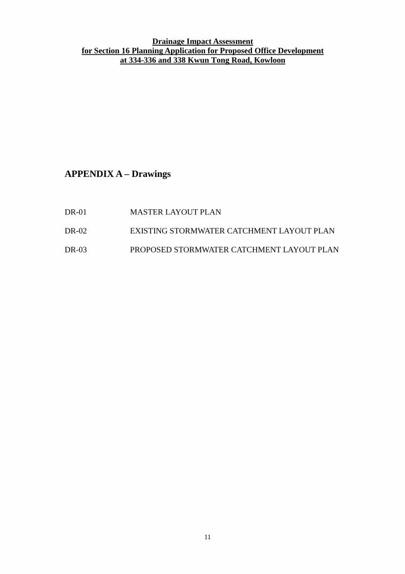
1.2.1 The proposed development site is located at the end of Tai Yip Street, Kwun Tong, Kowloon, Hong Kong. It is closed to Hong Kong Commercial Daily at Kwun Tong Road. The proposed development site is above sea level with a ground level of approx. +4.3mPD.
1.2.2 For the location of the subject site, please refer to Appendix A, Drawing
No. DR-01.
Drainage Impact Assessment for Section 16 Planning Application for Proposed Office Development
at 334-336 and 338 Kwun Tong Road, Kowloon
2
2.0 SCOPE OF ASSESSMENT
2.1 Study Objectives
2.1.1 The aim of the DIA includes:
(i) Catchment study and its flow path direction; (ii) Capacity checking of existing stormwater drains; (iii) Estimating the surface runoff from the proposed development; (iv) Proposing feasible discharge points to the existing stormwater drainage
system; (v) To evaluate any potential drainage impacts to the existing stormwater
drainage system owing to the proposed development; and (vi) To recommend feasible mitigation measures on the existing stormwater
drainage system.
Drainage Impact Assessment for Section 16 Planning Application for Proposed Office Development
at 334-336 and 338 Kwun Tong Road, Kowloon
3
3.0 REVIEW THE EXISTING SEWERAGE CONDITION
3.1 Site Topography 3.1.1 The topographic levels of Tai /Yip Street adjacent to the site are gradually sloping
downwards from northern west to southern east direction from +4.3mPD to +4.2mPD.
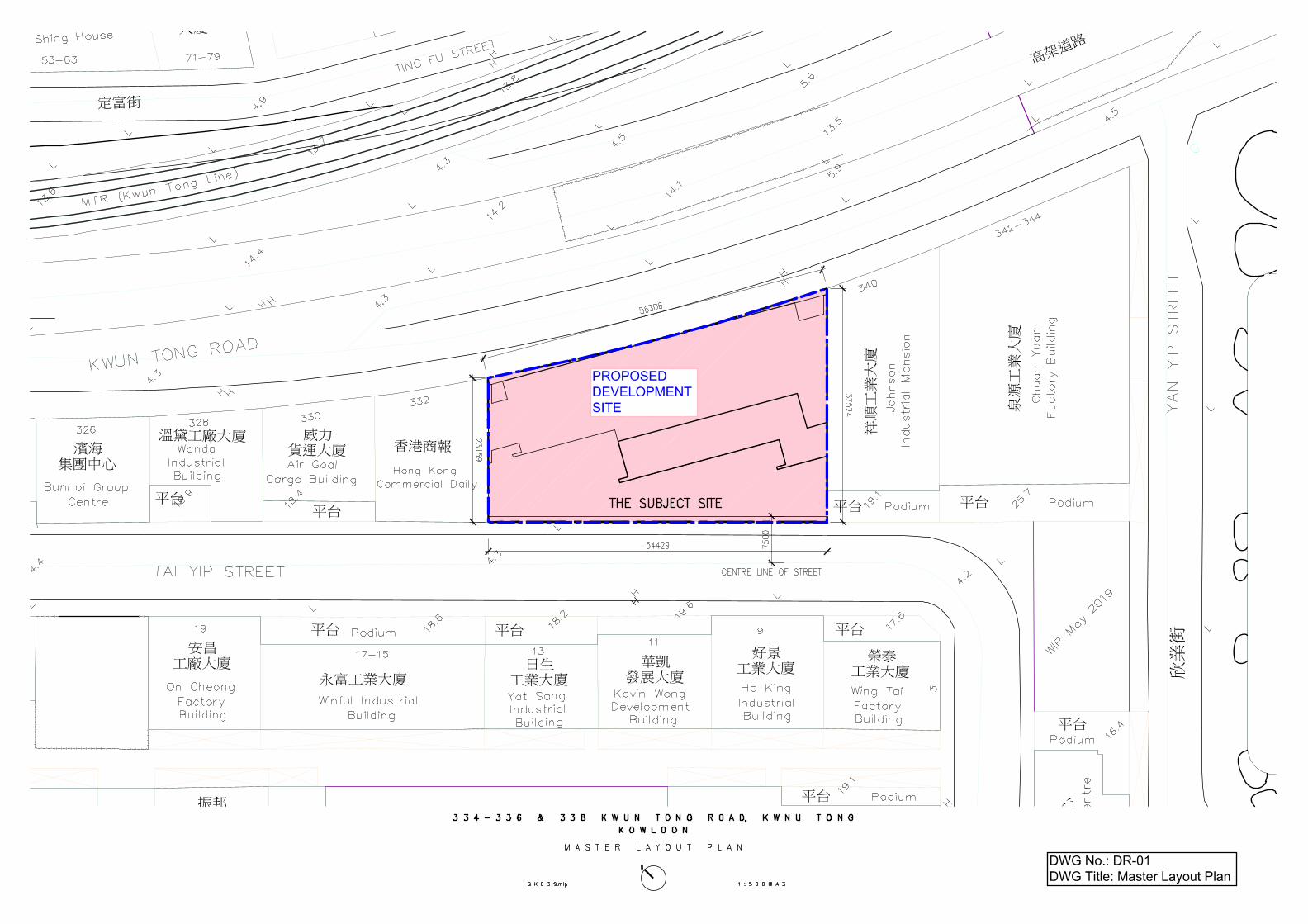
3.2 Existing Drainage and Catchment Study 3.2.1 According to the DSD drainage record plan, a series of stormwater drains with
diameter from 450mm to 600mm run along the section of Tai Yip Street nearby the subject site with varying pipe gradients from approx. 1:92.86 to 1:235.42. Currently, the existing surface drainage system conveys the runoff generated from pavement & carriageway at the northern west to western east sides of the site.
3.2.2 The existing drainage system serving the runoff generated from the adjacent
sub-catchments are listed below: 1. The development site, Site Area S1 and Site Area S2; 2. Area A1 – Pavement & carriageway of Tai Yip Street; 3. Area A2 – The building of 330 Kwun Tong Road; 4. Area A3 – The building of 332 Kwun Tong Road; 5. Area A4 – Pavement & carriageway of Tai Yip Street; 6. Area A5 – Pavement & carriageway of Tai Yip Street; 7. Area A6 – Pavement & carriageway of Tai Yip Street;
3.2.3 The existing stream course near the development site discharges the runoff
generated from the adjacent building and conveys the flows to the downstream 1-cell box culvert through 900mm diameter cross road pipes laid under Lai Yip Street.
Drainage Impact Assessment for Section 16 Planning Application for Proposed Office Development
at 334-336 and 338 Kwun Tong Road, Kowloon
4
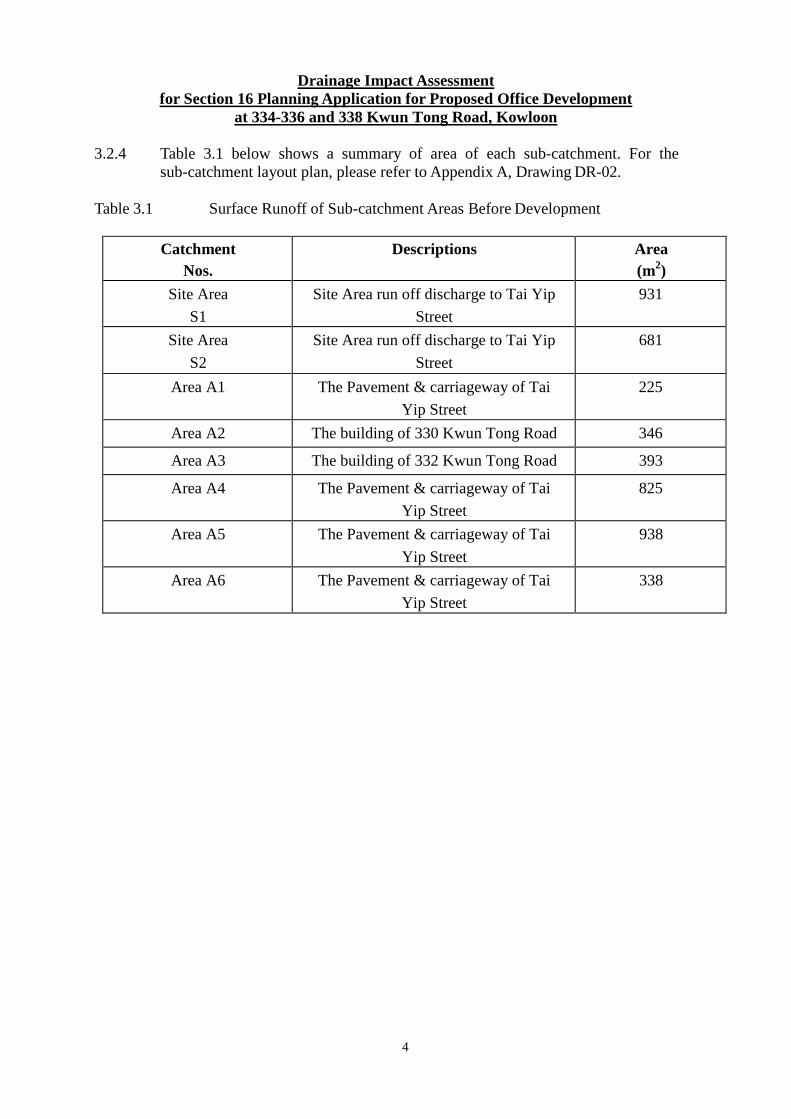
3.2.4 Table 3.1 below shows a summary of area of each sub-catchment. For the sub-catchment layout plan, please refer to Appendix A, Drawing DR-02.
Table 3.1 Surface Runoff of Sub-catchment Areas Before Development
Catchment Nos.
Descriptions Area (m2)
Site Area
S1
Site Area run off discharge to Tai Yip
Street
931
Site Area
S2
Site Area run off discharge to Tai Yip
Street
681
Area A1 The Pavement & carriageway of Tai
Yip Street
225
Area A2 The building of 330 Kwun Tong Road 346
Area A3 The building of 332 Kwun Tong Road 393
Area A4 The Pavement & carriageway of Tai
Yip Street
825
Area A5 The Pavement & carriageway of Tai
Yip Street
938
Area A6 The Pavement & carriageway of Tai
Yip Street
338
Drainage Impact Assessment for Section 16 Planning Application for Proposed Office Development
at 334-336 and 338 Kwun Tong Road, Kowloon
5
4. ESTIMATION OF PEAK RUN OFF 4.1 Peak Runoff from Existing Condition 4.1.1 Based on the Drainage Services Department’s Stormwater Drainage Manual
(SDM), the following assumptions were adopted in the assessment report.
(i) The drainage design calculations were carried out in accordance with the Rational Method as stated in the SDM; (ii) The rainfall intensity is based on the intensity-duration-frequency (IDF) relationship; and (iii) A 50-year return period was adopted to estimate the peak stormwater flows in compliance with DSD’s requirement. (iv) The Rainfall Increase due to Climate Change – End of 21st Century (2081 – 2100): i+13.8%.
4.1.2 For paved areas such as pavement, carriageway and building roof, an average
runoff coefficient of 0.9 is adopted. The estimation of the peak runoffs are based on the above runoff coefficients.
4.1.3 Design Assumption:
• Rational method adopted for peak runoff estimation
• Return period for rainfall intensity adopted is 1-in-50 years
• Colebrook-White roughness coefficient for precast concrete pipe (stormwater), ks = 0.6mm
• Time of entry = 0.382min (Time of Entry of Area S1 + S2)
• Minimum velocity for pipe flow = 1.00m/s
• Pipe material to be precast concrete pipe to BS5911
• Runoff coefficient = 0.9 for hard-paved area
• Rainfall Increase due to Climate Change = 113.8% (1.138)
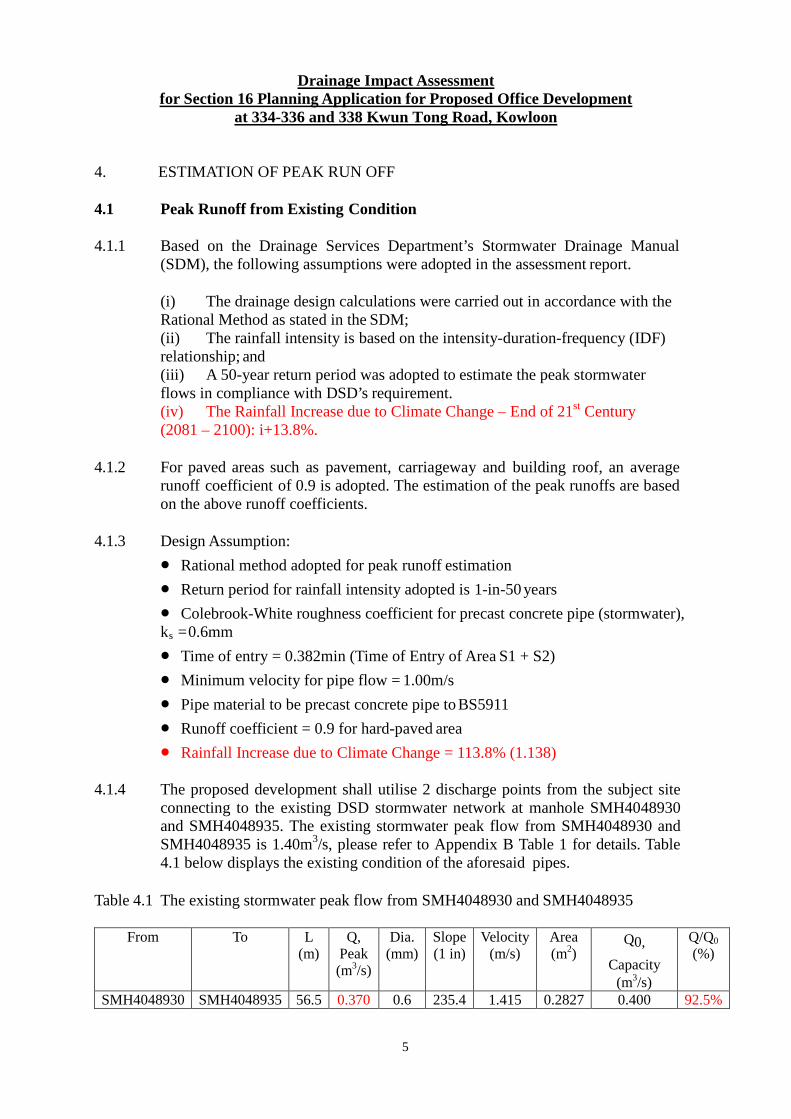
4.1.4 The proposed development shall utilise 2 discharge points from the subject site connecting to the existing DSD stormwater network at manhole SMH4048930 and SMH4048935. The existing stormwater peak flow from SMH4048930 and SMH4048935 is 1.40m3/s, please refer to Appendix B Table 1 for details. Table 4.1 below displays the existing condition of the aforesaid pipes.
Table 4.1 The existing stormwater peak flow from SMH4048930 and SMH4048935
From To L (m)
Q, Peak (m3/s)
Dia. (mm)
Slope (1 in)
Velocity (m/s)
Area (m2)
Q0,
Capacity (m3/s)
Q/Q0 (%)
SMH4048930 SMH4048935 56.5 0.370 0.6 235.4 1.415 0.2827 0.400 92.5%
Drainage Impact Assessment for Section 16 Planning Application for Proposed Office Development
at 334-336 and 338 Kwun Tong Road, Kowloon
6
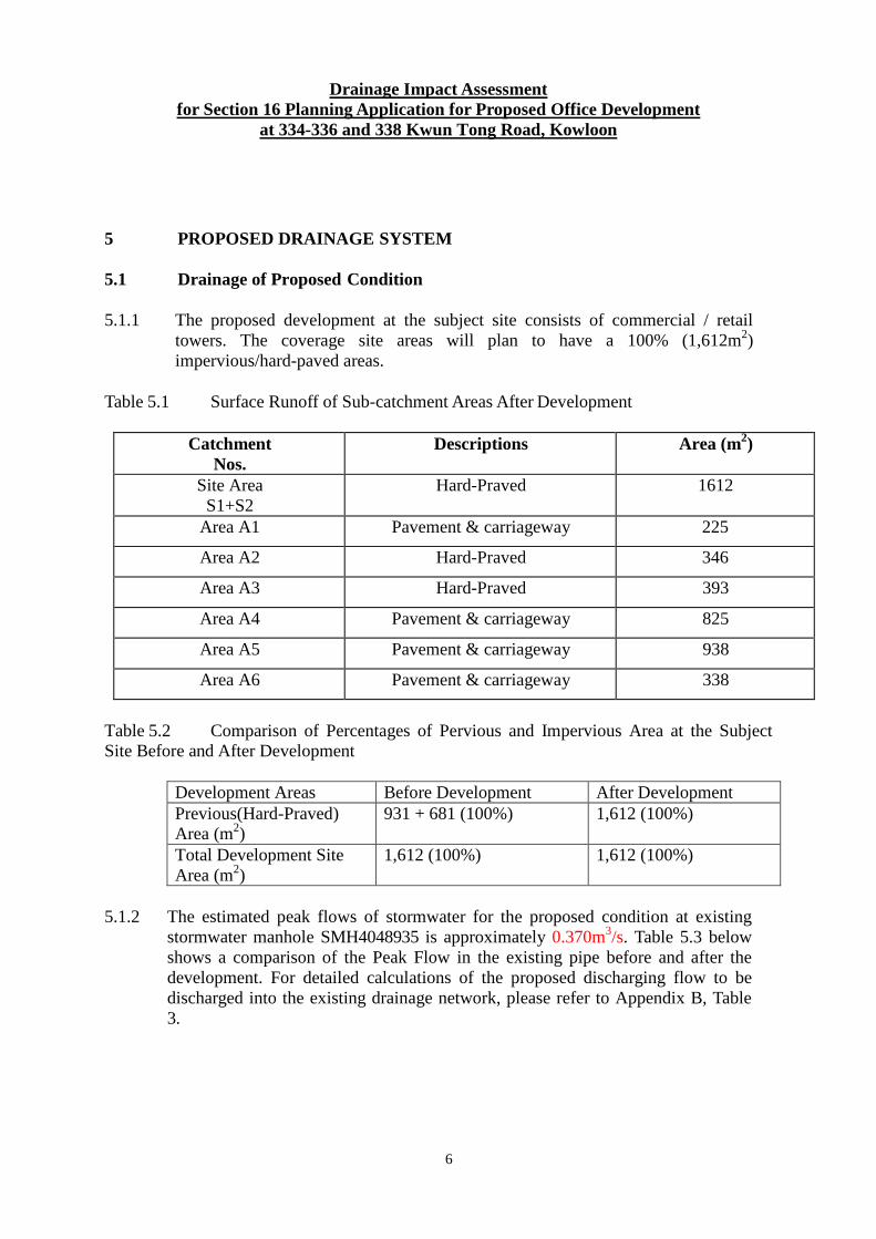
5 PROPOSED DRAINAGE SYSTEM 5.1 Drainage of Proposed Condition 5.1.1 The proposed development at the subject site consists of commercial / retail
towers. The coverage site areas will plan to have a 100% (1,612m2) impervious/hard-paved areas.
Table 5.1 Surface Runoff of Sub-catchment Areas After Development
Catchment Nos.
Descriptions Area (m2)
Site Area S1+S2
Hard-Praved 1612
Area A1 Pavement & carriageway 225
Area A2 Hard-Praved 346
Area A3 Hard-Praved 393
Area A4 Pavement & carriageway 825
Area A5 Pavement & carriageway 938
Area A6 Pavement & carriageway 338
Table 5.2 Comparison of Percentages of Pervious and Impervious Area at the Subject Site Before and After Development
Development Areas Before Development After Development Previous(Hard-Praved) Area (m2)
931 + 681 (100%) 1,612 (100%)
Total Development Site Area (m2)
1,612 (100%) 1,612 (100%)
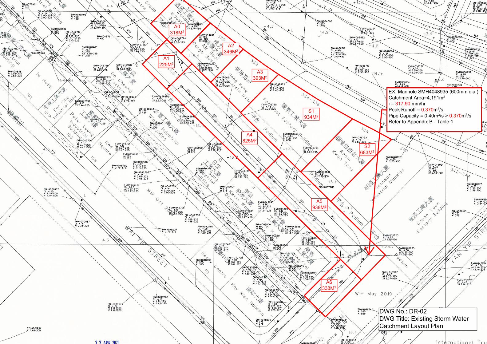
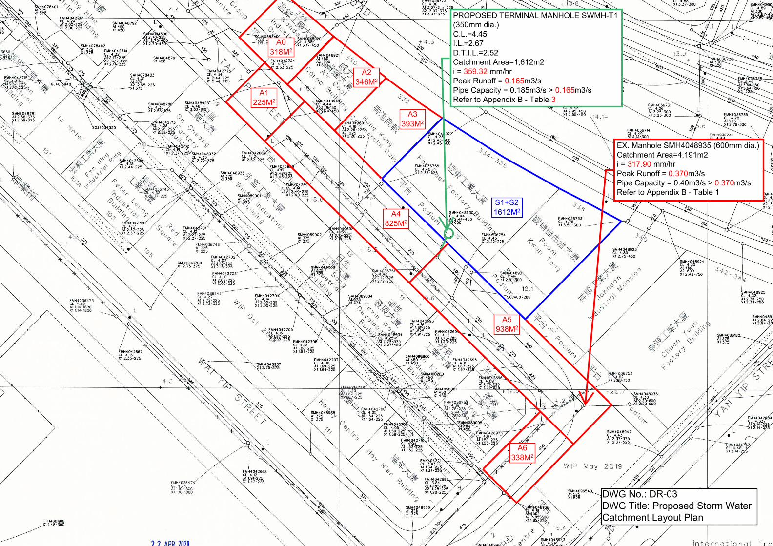
5.1.2 The estimated peak flows of stormwater for the proposed condition at existing
stormwater manhole SMH4048935 is approximately 0.370m3/s. Table 5.3 below shows a comparison of the Peak Flow in the existing pipe before and after the development. For detailed calculations of the proposed discharging flow to be discharged into the existing drainage network, please refer to Appendix B, Table 3.
Drainage Impact Assessment for Section 16 Planning Application for Proposed Office Development
at 334-336 and 338 Kwun Tong Road, Kowloon
7
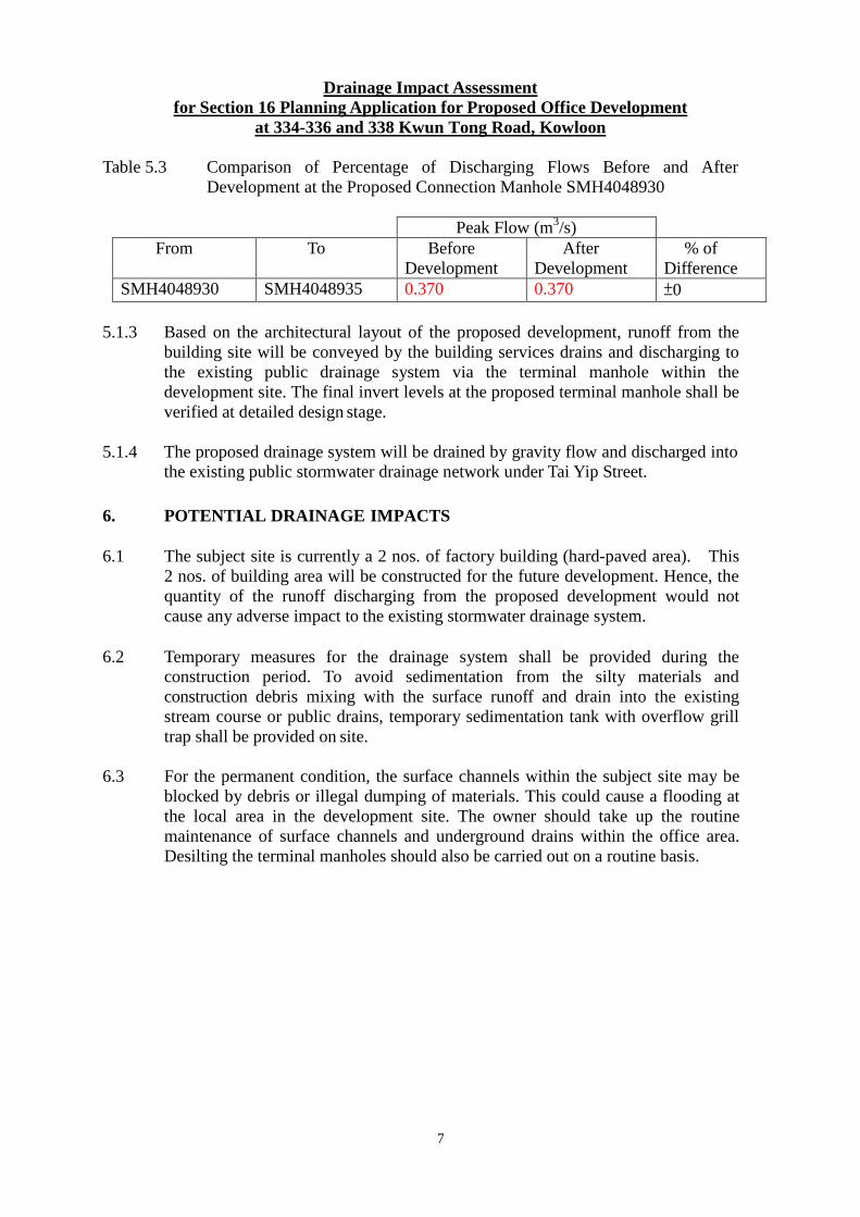
Table 5.3 Comparison of Percentage of Discharging Flows Before and After Development at the Proposed Connection Manhole SMH4048930
Peak Flow (m3/s)
From To Before Development
After Development
% of Difference
SMH4048930 SMH4048935 0.370 0.370 ±0 5.1.3 Based on the architectural layout of the proposed development, runoff from the
building site will be conveyed by the building services drains and discharging to the existing public drainage system via the terminal manhole within the development site. The final invert levels at the proposed terminal manhole shall be verified at detailed design stage.
5.1.4 The proposed drainage system will be drained by gravity flow and discharged into
the existing public stormwater drainage network under Tai Yip Street.
6. POTENTIAL DRAINAGE IMPACTS 6.1 The subject site is currently a 2 nos. of factory building (hard-paved area). This
2 nos. of building area will be constructed for the future development. Hence, the quantity of the runoff discharging from the proposed development would not cause any adverse impact to the existing stormwater drainage system.
6.2 Temporary measures for the drainage system shall be provided during the
construction period. To avoid sedimentation from the silty materials and construction debris mixing with the surface runoff and drain into the existing stream course or public drains, temporary sedimentation tank with overflow grill trap shall be provided on site.
6.3 For the permanent condition, the surface channels within the subject site may be
blocked by debris or illegal dumping of materials. This could cause a flooding at the local area in the development site. The owner should take up the routine maintenance of surface channels and underground drains within the office area. Desilting the terminal manholes should also be carried out on a routine basis.

Drainage Impact Assessment for Section 16 Planning Application for Proposed Office Development
at 334-336 and 338 Kwun Tong Road, Kowloon
8
6.4 The following Table 6.1 summarizes the rating of potential impacts and mitigation
measures. Table 6.1 Potential Drainage Impacts and Mitigation Measures
Potential Impacts
Description
Rating of Impacts
(H=High, M=Medium,
L=Low)
Proposed Mitigation
Measures
Flooding within development site and adjacent areas
Flooding may occur during serve heavy rainstorm.
L - Formation levels shall have adequate gradients for gravitational discharge runoff.
- Regular inspection of drainage facilities e.g. : U-channels, catchpits, underground drainage pipes and manholes.
Obstruction of sediment and debris during the construction period
Generating the sedimentation materials during the construction period and/or debris wash-off from stockpiled materials which may cause downstream drainage system.
M - Regular inspection of drainage system.
- Catchpits with desilting traps shall be constructed in the drainage system.
Obstruction of sediment and debris post-construction and during operation
Blockage of U-channels within the subject site due to runoff debris.
M - Routine maintenance of the drainage system.
- Desilting of the drainage facilities, e.g.: surface channels, underground drain pipes and manholes routinely.
- Petrol interceptors and catchpits should be provided in the drainage system.
Drainage Impact Assessment for Section 16 Planning Application for Proposed Office Development
at 334-336 and 338 Kwun Tong Road, Kowloon
9
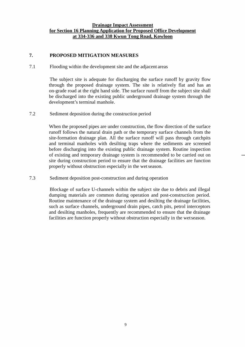
7. PROPOSED MITIGATION MEASURES 7.1 Flooding within the development site and the adjacent areas
The subject site is adequate for discharging the surface runoff by gravity flow through the proposed drainage system. The site is relatively flat and has an on-grade road at the right hand side. The surface runoff from the subject site shall be discharged into the existing public underground drainage system through the development’s terminal manhole.
7.2 Sediment deposition during the construction period
When the proposed pipes are under construction, the flow direction of the surface runoff follows the natural drain path or the temporary surface channels from the site-formation drainage plan. All the surface runoff will pass through catchpits and terminal manholes with desilting traps where the sediments are screened before discharging into the existing public drainage system. Routine inspection of existing and temporary drainage system is recommended to be carried out on site during construction period to ensure that the drainage facilities are function properly without obstruction especially in the wet season.
7.3 Sediment deposition post-construction and during operation
Blockage of surface U-channels within the subject site due to debris and illegal dumping materials are common during operation and post-construction period. Routine maintenance of the drainage system and desilting the drainage facilities, such as surface channels, underground drain pipes, catch pits, petrol interceptors and desilting manholes, frequently are recommended to ensure that the drainage facilities are function properly without obstruction especially in the wet season.
Drainage Impact Assessment for Section 16 Planning Application for Proposed Office Development
at 334-336 and 338 Kwun Tong Road, Kowloon
10
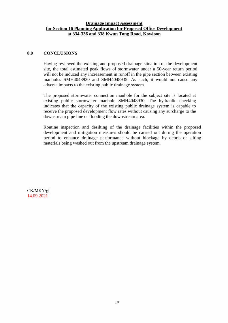
8.0 CONCLUSIONS
Having reviewed the existing and proposed drainage situation of the development site, the total estimated peak flows of stormwater under a 50-year return period will not be induced any increasement in runoff in the pipe section between existing manholes SMH4048930 and SMH4048935. As such, it would not cause any adverse impacts to the existing public drainage system. The proposed stormwater connection manhole for the subject site is located at existing public stormwater manhole SMH4048930. The hydraulic checking indicates that the capacity of the existing public drainage system is capable to receive the proposed development flow rates without causing any surcharge to the downstream pipe line or flooding the downstream area. Routine inspection and desilting of the drainage facilities within the proposed development and mitigation measures should be carried out during the operation period to enhance drainage performance without blockage by debris or silting materials being washed out from the upstream drainage system.
CK/MKY/gi 14.09.2021
Drainage Impact Assessment for Section 16 Planning Application for Proposed Office Development
at 334-336 and 338 Kwun Tong Road, Kowloon
11
APPENDIX A – Drawings DR-01 MASTER LAYOUT PLAN DR-02 EXISTING STORMWATER CATCHMENT LAYOUT PLAN DR-03 PROPOSED STORMWATER CATCHMENT LAYOUT PLAN
A0 318M2
A0 318M2
Drainage Impact Assessment for Section 16 Planning Application for Proposed Office Development
at 334-336 and 338 Kwun Tong Road, Kowloon
12
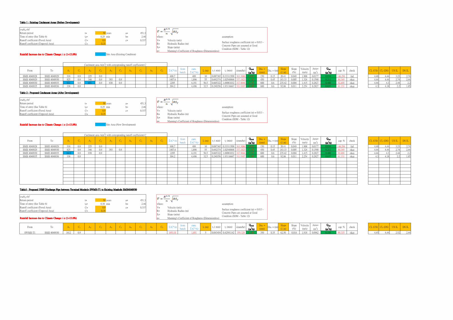
APPENDIX B – Hydraulic Calculations Table 1 Existing Catchment Areas (Before Development)
Table 2 Proposed Catchment Areas (After Development)
Table 3 Proposed 350Ø Discharge Pipe between Terminal Manhole
SWMH-T1 to existing manhole SMH4048930 Table 4 Calculations for Time of Entry
t= 50 years a= 451.3
t0= 0.25 min b= 2.46 where: assumption:
C= 0.9 c= 0.337 V= Velocity (m/s)
C= 0.35 R= Hydraulic Radius (m)
Sf= Slope (m/m)
n= Manning's Coefficient of Roughness (Dimensionless)
Rainfall Increase due to Climate Change: i x (1+13.8%)Rainfall Increase due to Climate Change: i x (1+13.8%)Rainfall Increase due to Climate Change: i x (1+13.8%)Rainfall Increase due to Climate Change: i x (1+13.8%) Site Area (Existing Condition)
From To A1 C1 A2 C2 A3 C3 A4 C3 A5 C5 Σ(C*A)from
banch
cum.
Σ(C*A)L (m) tf ( min) tc (min) i(mm/hr)
QQQQpeakpeakpeakpeak
(m(m(m(m3333/s)/s)/s)/s)
Dia. =
(mm)Dia. = (m)
Slope
(1 in)
Slope
(%)
Velocity
(m/s)
Area=
(m2)
QQQQcapcapcapcap
(m(m(m(m3333/s)/s)/s)/s)
cap. % check CL (US) CL (DS) US IL DS IL
SMH 4048928 SMH 4048929 318 0.9 225 0.9 488.7 489 10 0.087365 0.33311509 363.3086 0.049 150 0.15 20.41 0.049 1.908 0.0177 0.034 146.296 fail 4.48 4.44 3.23 2.74
SMH 4048929 SMH 4048930 825 0.9 346 0.9 393 0.9 1407.6 1,896 55 0.692374 1.02548868 337.1823 0.178 450 0.45 183.33 0.005 1.324 0.1590 0.211 84.349 okay 4.44 4.44 2.74 2.44
SMH 4048930 SMH 4048935 931 0.9 681 0.9 938 0.9 2295 4,191 56.5 0.665322 1.69081032 317.9046 0.370 600 0.6 235.42 0.004 1.415 0.2827 0.400 92.488 okay 4.44 4.3 2.44 2.2
SMH 4048935 SMH 4048936 338 0.9 304.2 4,496 32.5 0.240356 1.93116667 311.9307 0.390 600 0.6 92.86 0.011 2.254 0.2827 0.637 61.131 okay 4.3 4.18 2.2 1.85
t= 50 years a= 451.3
t0= 0.25 min b= 2.46 where: assumption:
C= 0.9 c= 0.337 V= Velocity (m/s)
C= 0.35 R= Hydraulic Radius (m)
Sf= Slope (m/m)
n= Manning's Coefficient of Roughness (Dimensionless)
Rainfall Increase due to Climate Change: i x (1+13.8%)Rainfall Increase due to Climate Change: i x (1+13.8%)Rainfall Increase due to Climate Change: i x (1+13.8%)Rainfall Increase due to Climate Change: i x (1+13.8%) Site Area (New Development)
From To A1 C1 A2 C2 A3 C3 A4 C3 A5 C5 Σ(C*A)from
banch
cum.
Σ(C*A)L (m) tf ( min) tc (min) i(mm/hr)
QQQQpeakpeakpeakpeak
(m(m(m(m3333/s)/s)/s)/s)
Dia. =
(mm)Dia. = (m)
Slope
(1 in)
Slope
(%)
Velocity
(m/s)
Area=
(m2)
QQQQcapcapcapcap
(m(m(m(m3333/s)/s)/s)/s)
cap. % check CL (US) CL (DS) US IL DS IL
SMH 4048928 SMH 4048929 318 0.9 225 0.9 488.7 489 10 0.087365 0.33311509 363.3086 0.049 150 0.15 20.41 0.049 1.908 0.0177 0.034 146.296 fail 4.48 4.44 3.23 2.74
SMH 4048929 SMH 4048930 825 0.9 346 0.9 393 0.9 1407.6 1,896 55 0.692374 1.02548868 337.1823 0.178 450 0.45 183.33 0.005 1.324 0.1590 0.211 84.349 okay 4.44 4.44 2.74 2.44
SMH 4048930 SMH 4048935 1612 0.9 938 0.9 2295 4,191 56.5 0.665322 1.69081032 317.9046 0.370 600 0.6 235.42 0.004 1.415 0.2827 0.400 92.488 okay 4.44 4.3 2.44 2.2
SMH 4048935 SMH 4048936 338 0.9 304.2 4,496 32.5 0.240356 1.93116667 311.9307 0.390 600 0.6 92.86 0.011 2.254 0.2827 0.637 61.131 okay 4.3 4.18 2.2 1.85
t= 50 years a= 451.3
t0= 0.38 min b= 2.46 where: assumption:
C= 0.9 c= 0.337 V= Velocity (m/s)
C= 0.35 R= Hydraulic Radius (m)
Sf= Slope (m/m)
Rainfall Increase due to Climate Change: i x (1+13.8%)Rainfall Increase due to Climate Change: i x (1+13.8%)Rainfall Increase due to Climate Change: i x (1+13.8%)Rainfall Increase due to Climate Change: i x (1+13.8%) n= Manning's Coefficient of Roughness (Dimensionless)
From To A1 C1 A2 C2 A3 C3 A4 C3 A5 C5 Σ(C*A)from
banch
cum.
Σ(C*A)L (m) tf ( min) tc (min) i(mm/hr)
QQQQpeakpeakpeakpeak
(m(m(m(m3333/s)/s)/s)/s)
Dia. =
(mm)Dia. = (m)
Slope
(1 in)
Slope
(%)
Velocity
(m/s)
Area=
(m2)
QQQQcapcapcapcap
(m(m(m(m3333/s)/s)/s)/s)
cap. % check CL (US) CL (DS) US IL DS IL
SWMH-T1 SMH 4048930 1612 0.9 1651.01 1,651 5 0.043454 0.42591142 359.329 0.165 350 0.35 62.50 0.016 1.918 0.0962 0.185 89.315 okay 4.45 4.44 2.52 2.44
Surface roughness coefficient (n) = 0.013 -
Concrete Pipes are assumed at Good
Condition (SDM - Table 12)
Surface roughness coefficient (n) = 0.013 -
Concrete Pipes are assumed at Good
Condition (SDM - Table 12)
Surface roughness coefficient (n) = 0.013 -
Concrete Pipes are assumed at Good
Condition (SDM - Table 12)
Time of entry (See Table 6)
Runoff coefficient (Paved Area)
Runoff coefficient (Unpaved Area)
Table 3 : Proposed 350Ø Discharge Pipe between Terminal Manhole SWMH-T1 to Existing Manhole SMH4048930Table 3 : Proposed 350Ø Discharge Pipe between Terminal Manhole SWMH-T1 to Existing Manhole SMH4048930Table 3 : Proposed 350Ø Discharge Pipe between Terminal Manhole SWMH-T1 to Existing Manhole SMH4048930Table 3 : Proposed 350Ø Discharge Pipe between Terminal Manhole SWMH-T1 to Existing Manhole SMH4048930
i=a/(td+b)c
Return period
Time of entry (See Table 6)
Runoff coefficient (Paved Area)
Runoff coefficient (Unpaved Area)
Catchment area A(m2) with corresponding runoff coefficiernt C
Table 2 : Proposed Catchment Areas (After Development)Table 2 : Proposed Catchment Areas (After Development)Table 2 : Proposed Catchment Areas (After Development)Table 2 : Proposed Catchment Areas (After Development)
i=a/(td+b)c
Return period
Catchment area A(m2) with corresponding runoff coefficiernt C
Table 1 : Existing Catchment Areas (Before Development)Table 1 : Existing Catchment Areas (Before Development)Table 1 : Existing Catchment Areas (Before Development)Table 1 : Existing Catchment Areas (Before Development)
i=a/(td+b)c
Return period
Time of entry (See Table 6)
Runoff coefficient (Paved Area)
Runoff coefficient (Unpaved Area)
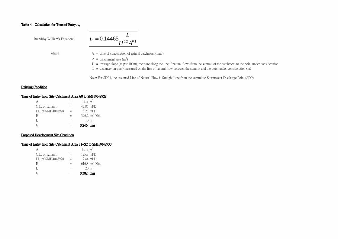
Table 4 - Calculation for Time of Entry, tTable 4 - Calculation for Time of Entry, tTable 4 - Calculation for Time of Entry, tTable 4 - Calculation for Time of Entry, t0000
t0 = time of concetration of natural catchment (min.)
A = catachment area (m2)
H = average slope (m per 100m), measure along the line if natural flow, from the summit of the catchment to the point under consideration
L = distance (on plan) measured on the line of natural flow between the summit and the point under consideration (m)
Note: For SDP1, the assumed Line of Natural Flow is Straight Line from the summit to Stormwater Discharge Point (SDP)
Existing ConditionExisting ConditionExisting ConditionExisting Condition
Time of Entry from Site Catchment Area A0 to SMH4048928Time of Entry from Site Catchment Area A0 to SMH4048928Time of Entry from Site Catchment Area A0 to SMH4048928Time of Entry from Site Catchment Area A0 to SMH4048928
A = 318 m2
G.L. of summit = 42.85 mPD
I.L. of SMH4048928 = 3.23 mPD
H = 396.2 m/100m
L = 10 m
t0 = 0.2460.2460.2460.246 minminminmin
Proposed Development Site ConditionProposed Development Site ConditionProposed Development Site ConditionProposed Development Site Condition
Time of Entry from Site Catchment Area S1+S2 to SMH4048930Time of Entry from Site Catchment Area S1+S2 to SMH4048930Time of Entry from Site Catchment Area S1+S2 to SMH4048930Time of Entry from Site Catchment Area S1+S2 to SMH4048930
A = 1612 m2
G.L. of summit = 125.8 mPD
I.L. of SMH4048928 = 2.44 mPD
H = 616.8 m/100m
L = 20 m
t0 = 0.3820.3820.3820.382 minminminmin
Brandsby William's Equation:
where
1.02.00 14465.0AH
Lt =