an interconnect architecture for networking systems on chips
TRANSCRIPT
36
To meet the demands of ever-increas-ing Internet traffic, the next generation of Inter-net backbone routers must deliver ultrahighperformance over an optical infrastructure. Atthe current Internet traffic growth rate, networkservice providers will likely deploy OC-768routers in the foreseeable future. At the sametime, as Internet and application serviceproviders attempt to provide more diverse anddifferentiated services, routers will have to takeon new tasks. In addition to routing and pack-et forwarding, routers will likely perform pack-et classification, distinguishing packets andgrouping them according to their requirements;buffer management, determining buffer alloca-tion and admission control for packets; andpacket scheduling, determining how to sequencepackets to meet service level agreements (SLA).1
Traditionally, routers have used general-pur-pose reduced-instruction-set computer (RISC)processors or application-specific ICs (ASICs).Although general-purpose, processor-basedrouter architectures provide the flexibility toupgrade to new router tasks, they will not sat-isfy the growing speed requirements for new,complex, packet-processing tasks. On the otherhand, ASIC-based router implementations canprovide the speed but not the required pro-
gramming flexibility. These shortcomings oftraditional RISC and ASIC designs mean thatdesigners must develop new high-speed net-work processors that permit flexible program-mability and work at OC-768 speed.
At OC-768 (40 Gbps), IP packet arrival ratecould reach approximately 114 x 106 packetsper second (assuming 44 bytes per packet). Toensure that the worst-case time to process apacket does not exceed the packet arrival rateand thus violate SLAs, packet-processing timeshould be at most 9 ns per packet. To accom-modate this requirement, a network processormust perform approximately 500 instructionson each arriving packet to enable packet for-warding and classification on packet flows.Hence, an OC-768 network processor mustprocess 57 billion instructions per second, aperformance level a multiprocessor system-on-a-chip (SOC) architecture can provide.
Octagon is a novel on-chip communicationarchitecture that can meet the performancerequirements of network processor SOCs.Octagon’s cost, performance, and scalabilityadvantages make it suitable for the aggressiveon-chip communication demands of not onlynetworking SOCs, but also SOCs in severalother domains.
Faraydon Karim Anh Nguyen
STMicroelectronics
Sujit DeyUniversity of California,
San Diego
NETWORK PROCESSOR SYSTEMS ON CHIPS MEET THE SPEED AND FLEXIBILITY
REQUIREMENTS OF NEXT-GENERATION INTERNET ROUTERS. THE OCTAGON ON-
CHIP COMMUNICATION ARCHITECTURE, WITH ITS COST, PERFORMANCE, AND
SCALABILITY ADVANTAGES, SUPPORTS THESE NETWORK PROCESSOR SOCS.
0272-1732/02/$17.00 2002 IEEE
AN INTERCONNECT ARCHITECTUREFOR NETWORKINGSYSTEMS ON CHIPS
High-performance communicationsConsider the on-chip communication
requirements typical network processor appli-cations impose. Using T.V. Lakshman and D.Stiliadis’ packet classification algorithm withan estimated 10,000 classification rules and16-bit on-chip memory width,2 we must per-form 625 memory accesses per packet arrival,or 71.3 × 10⁹ memory accesses per second (inthe worst case). Clearly, this necessitates theuse of multiple memory components, and anon-chip communication architecture thatenables highly concurrent, high-speed com-munication between the multiple processorand memory components.
Recent studies have demonstrated the sig-nificant role an on-chip communication archi-tecture plays in determining a SOC’s overallperformance.3 Several techniques let us designand synthesize on-chip communication to sat-isfy components’ interface and communica-tion needs in an application-specific system.4–6
However, because one of a network processor’sprimary goals is to efficiently execute multipleapplications (including evolving networkingapplications), synthesizing an application-spe-cific interconnect architecture for a networkprocessor SOC will not work.
Rather than synthesize a custom on-chipinterconnect architecture for a given applica-tion, K. Lahiri and colleagues propose to opti-mally map a system’s communicationrequirements to a given communication archi-tecture.7 In other work, they describe a tech-nique that allows reconfiguration of theselected communication architecture’s proto-cols according to the application’s changingcommunication demands.8 Proposed com-munication mapping and reconfigurationtechniques provide up to an order of magni-tude improvement in system performance.Taken together, mapping and reconfigurationtechniques show promise for efficiently map-ping multiple applications to the same inter-connect fabric.7,8 For these techniques to besuccessful, however, developers must select theappropriate on-chip communication archi-tecture.
Despite recent advances in the analysis anddesign of high-performance on-chip commu-nication architectures, commercial SOCscommonly use simple bus-based topologiesand protocols.9,10 Even the Virtual Socket
Interface Alliance’s effortshave focused on bus interfacestandards.
Although bus-based on-chip communication mightbe suitable for many applica-tions, it clearly cannot satisfyan OC-768 network proces-sor’s very demanding on-chipcommunication needs. Forhigh-performance computingsystems, interconnect archi-tectures based on crossbars, orcrossbars mixed with buses,deliver the ultrahigh-perfor-mance communication need-ed among components.11
Many switching architec-tures in high-performancerouters also use crossbars.1 Anon-chip crossbar can satisfy the on-chip com-munication needs of an OC-768 networkprocessor SOC. Theoretically, crossbar per-formance (in terms of throughput or delay) ishigh enough to permit development of effi-cient network processing tasks.12 In reality,crossbar implementation costs are high: Cross-bars require many on-chip wires and relays tominimize clock skew across the chip. In addi-tion, crossbars do not scale well as the num-ber of nodes to be connected increases.Although crossbar-based interconnects mightbe justified in high-performance computingsystems and routers, they might not be the besteconomic choice for lower-cost and higher-volume network processor SOCs.
Octagon The Octagon on-chip architecture is sim-
pler to implement than a crossbar yet hasmuch higher throughput than either sharedbuses or traditional crossbars. Unlike cross-bars, Octagon’s implementation complexityincreases linearly with the number of nodes—processor or memory components—that thenetwork must connect.
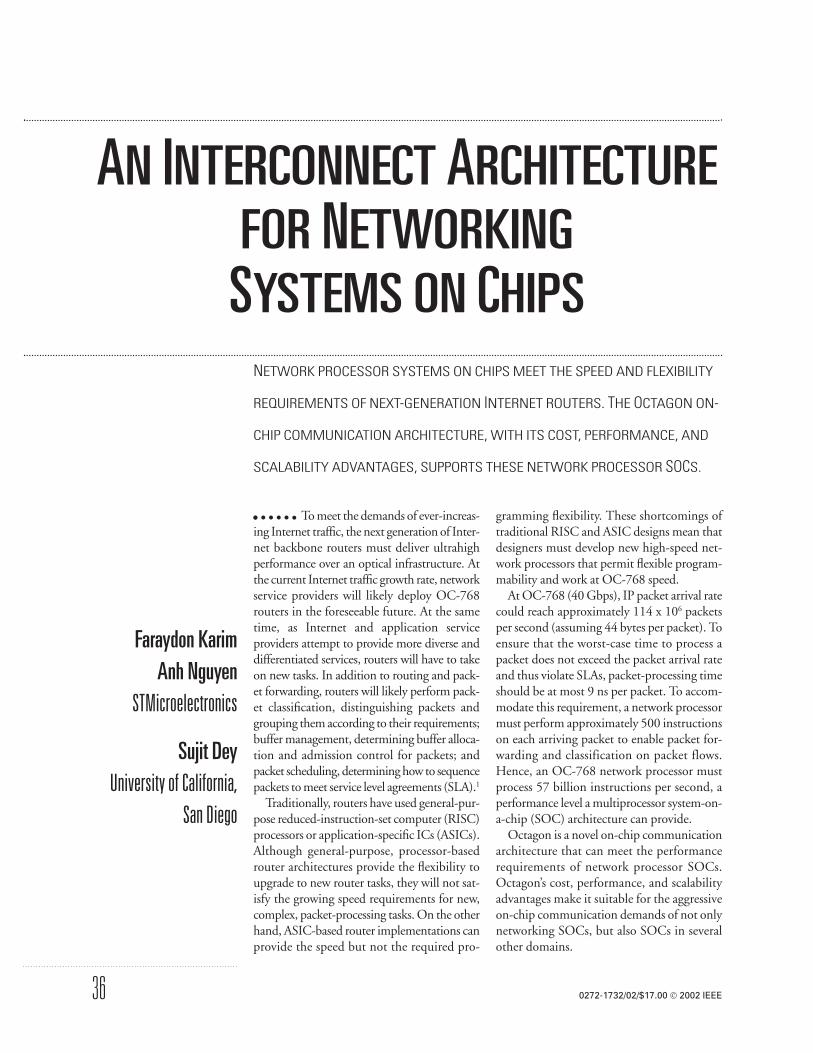
ArchitectureAs Figure 1 shows, a basic Octagon unit
consists of eight nodes and 12 bidirectionallinks.
The Octagon architecture has several desir-able properties:
37SEPTEMBER–OCTOBER 2002
0
4
6 2
1
3
7
5
Figure 1. Basic Octagon configurationincludes eight nodes and 12 bidirectionallinks.

• two-hop communication between anypair of nodes;
• higher aggregate throughput than a sharedbus or crossbar interconnect under certainimplementation conditions;
• simple, shortest-path routing algorithm;and
• less wiring than a crossbar interconnect.
Octagon operates in packet- or circuit-switched mode. An Octagon packet is datathat must be transferred from the destinationOctagon node to the source Octagon nodeas a result of a communication request by thesource node. An Octagon packet can be fixedor variable length. In packet-switched mode,the network nodes buffer packets at inter-mediate nodes if there is contention at theegress link.
In circuit-switched mode, a networkarbiter allocates the entire path betweensource and destination nodes of a communi-cating node pair for a number of clock cycles.Nonoverlapping communication paths canoccur concurrently—that is, the arbiter per-mits spatial reuse. In this mode, system per-formance is a function of the chosenconnection schedule. The question is, then,given the set of pending communicationrequests, how should the arbiter scheduleconnections to optimize throughput (or someother metric)? We have developed a simpleconnection scheduler, called the best-fit algo-rithm (described later), to enable Octagon’scircuit-switched mode.
Packet routingWe can code Octagon node addresses into
a three-bit field and route an Octagon packetas follows. We prepend a three-bit tag to eachpacket. Each node compares the tag (Pack-et_addr) to its own address (Node_addr) todetermine the next action. The node com-putes the relative address of a packet as
Rel_addr = Packet_addr − Node
addr (modulo 8)
At each node on the Octagon, packet rout-ing is a function of Rel_addr:
• Rel_addr = 0, process at node• Rel_addr = 1 or 2, route clockwise• Rel_addr = 6 or 7, route counterclock-
wise• Route across otherwise
Consequently, a predetermined, simple rout-ing scheme for each network packet permits atmost two hops to separate any two nodes.
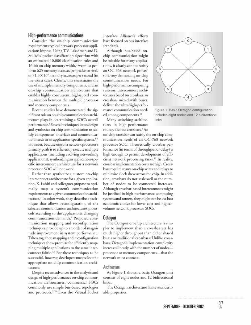
Implementation cost Figure 2 illustrates the physical layout of
the Octagon and crossbar interconnect archi-tectures. In our network processor, each Octa-gon node consists of a processor-memory pairwith an estimated size of 2 mm × 2 mm. Letus assume that the minimum wire spacing is0.2 µm, and the width of a 32-bit link is12µm (including individual wire width, spac-ing, and shielding). As Figure 2a shows, the
38
NETWORK SOC COMMUNICATIONS
IEEE MICRO
4
30
7
21
6 5
10 2 3
67 5 4
(a) (b)
Figure 2. Octagon (a) and crossbar (b) physical-layout schematic examples. Octagon consistsof 12 horizontal and 12 vertical 32-bit tracks with each horizontal track upper-bounded by 8mm, and each vertical track upper-bounded by 0.156 micron (13 x 12 micron). The crossbarhas eight horizontal and 32 vertical 32-bit tracks, with the horizontal tracks upper-bounded by8 mm as in the Octagon, and the vertical tracks upper-bounded by 0.108 micron (9 x 12
Octagon architecture consists of 12 horizon-tal and 12 vertical 32-bit tracks. Each hori-zontal track is upper-bounded by 8 mm, thetotal width of the four nodes. Each verticaltrack is upper-bounded by 0.156 micron (13× 12 micron). As Figure 2b shows, the cross-bar needs eight horizontal and 32 vertical 32-bit tracks. Although the horizontal tracks areupper-bounded by 8 mm as in the Octagon,the vertical tracks are upper-bounded by0.108 micron (9 × 12 micron). Thus, wiringin Octagon is less complex than in a crossbar.
Octagon versus crossbars and busesConsider a typical SOC communication.
Node processes continuously generate requestsfor service; examples include memory read andwrite requests. We classify requests accordingto their source-destination pair; thus, we denoterequests that originate from node i with desti-nation node j as type ij. Requests of type ijarrive at the system following the Poissonprocess with parameter λij, which is therequests’ arrival rate. Service time is the time adestination node requires to complete allrequested tasks if it processes the request in iso-lation. We assume the communication linksbetween source and destination nodes arelocked until service is completed.
Service and response timesThe required service time is equivalent to
packet size or link rate, where packet size isthe number of bytes of data transfer that resultfrom the communication request, and linkrate is the communication link’s data transferrate. We assume that the service time forrequest ij is exponentially distributed withparameter µij, with 1/µij as the average servicetime per request—a reasonable assumptionbecause packet length varies and, in the mostgeneral case, could range from one to thou-sands of bytes. For example, if a node issues aread request for an 8-byte data block, then fora 1-MHz 8-bit wide data bus, the request ser-vice time is 8 microseconds.
We can easily extend these assumptions toaccommodate other discrete-timed distribu-tion such as Bernoulli arrivals, and geometricor deterministic service time. We consider asymmetric system where λij = λ, ∀i,j and µij =µ, ∀i j. The utilization of requests type ij isλij = λij/µij = λ/µ = λ. Utilization is the aver-
age amount of service demand arriving with-in one time unit. The aggregated arrival rateis λtot = Sij λ ij. Total utilization ρtotal = λ tot /µ.
We model the shared bus as a single serverqueue with Poisson arrivals and exponentialservice time. Consider the aggregated requestarrival process for the eight nodes. Because theindividual arrival process is a Poisson distrib-ution, the superposition is also a Poisson dis-tribution.12 In memory access applications,service rate corresponds to memory accessspeed. We ignore all propagation delays. Theserver serves queued requests in first-in, first-out (FIFO) order. An arriving request’sresponse time is the difference between thearrival time and time the bus completes theservice. Because the server is work conserv-ing,13 the expected response time, denoted byEWbus, for an arbitrary request arriving at thesingle server queue is identical to that for asingle-server multiple-queue system. Theexpected response time of a shared bus mod-eled by a single-server queue is
13
For crossbar throughput, we use the modelpresented by J. Chen and T. Stern.12 Theyshowed that for a large switch (approximate-ly 20 nodes) having a speedup factor of one,response time is
Chen and Stern also investigated the impactof various arbitration policies on switch per-formance. They found that arbitration poli-cies do not affect maximum throughputbecause it is only a function of the average ser-vice. Different arbitration policies result indifferent response times, however.
Communication request schedulingWe investigate the Octagon architecture per-
formance through simulation, using a simplerequest-response traffic model. That is, a source
EW EWE W
EW
EW p
p
xbar ss
s
s o
o
= +−( )
=−( )
+
= −
λλ
λ
µ λ µ
ρ
tot
tot
tot
tot
tot
where
and
2
2
2 88
8
1
18
,
,
.
EWbus =
−( )ρ
λ ρtot
tot tot1.
39SEPTEMBER–OCTOBER 2002
node generates a request to send to a destina-tion node. It eventually establishes a connectionfor the communication. For each connection,the source node sends a request and receives aresponse. After the communications, the par-
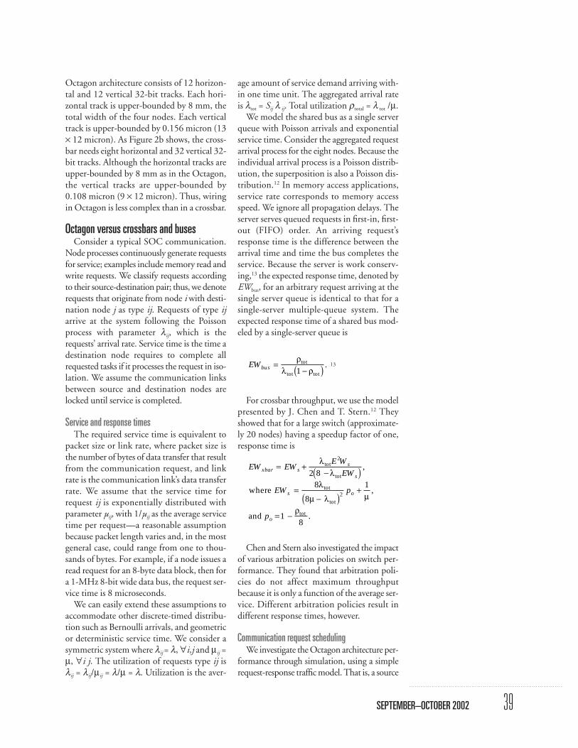
ticipating nodes sever the connection. We associate a processor and memory mod-
ule with each node, as Figure 3 shows. Appli-cations of this traffic model exist in routingtable lookup, Internet protocol packet classi-fication, and other networking functionswhere each node generates memory accessrequests. If the requested memory location isattached to the local node, then it generates noOctagon communication requests. Otherwise,it must forward the request to the appropriatenode via Octagon using the routing algorithmpreviously presented. At the destination node,the memory request consumes several clockcycles before spawning a response, which itreturns to the originating node.
The best-fit scheduler is a connection-ori-ented communication protocol that can simul-taneously accommodate nonoverlappingconnections. Each node maintains three queuesof outstanding requests, one for each egresslink. With respect to the overall network, thisglobal scheduler gives priority to the head-of-line requests in arrival time order (lower arrivaltime implies higher priority). At every servicecompletion time, the scheduler checks to see ifit can make new connections based on the pre-viously described priority scheme. The sched-uler sets up connections until it canaccommodate no more without violating thenonoverlapping rule. Note that we only con-sider head-of-line requests at each node. Whena connection is torn down, the scheduler reac-tivates to check if it can set up new connections.
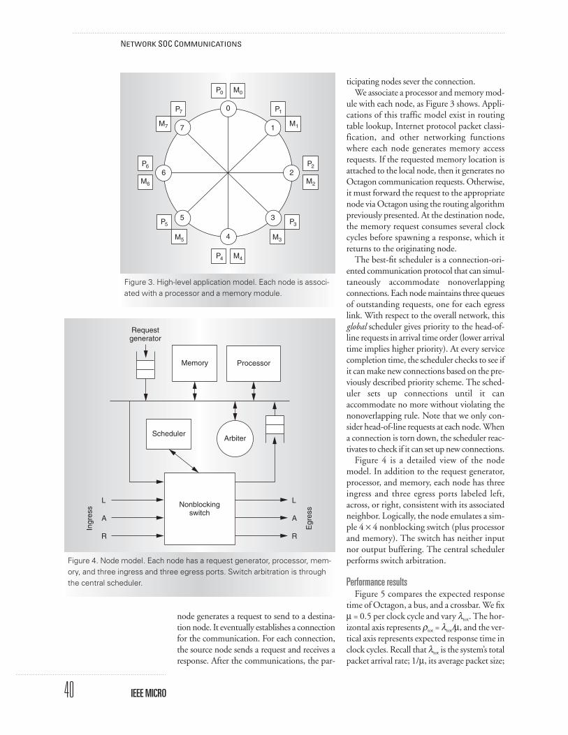
Figure 4 is a detailed view of the nodemodel. In addition to the request generator,processor, and memory, each node has threeingress and three egress ports labeled left,across, or right, consistent with its associatedneighbor. Logically, the node emulates a sim-ple 4 × 4 nonblocking switch (plus processorand memory). The switch has neither inputnor output buffering. The central schedulerperforms switch arbitration.
Performance resultsFigure 5 compares the expected response
time of Octagon, a bus, and a crossbar. We fixµ = 0.5 per clock cycle and vary λtot. The hor-izontal axis represents ρtot = λtot/µ, and the ver-tical axis represents expected response time inclock cycles. Recall that λtot is the system’s totalpacket arrival rate; 1/µ, its average packet size;
40
NETWORK SOC COMMUNICATIONS
IEEE MICRO
0
4
6 2
1
3
7
5
P0 M0
P7
M7
P1
M1
P6
M6
P5
M5
P3
M3
P2
M2
P4 M4
Figure 3. High-level application model. Each node is associ-ated with a processor and a memory module.
A
L
R
A
L
R
Scheduler
Requestgenerator
Memory Processor
Arbiter
Nonblockingswitch
Ingr
ess
Egr
ess
Figure 4. Node model. Each node has a request generator, processor, mem-ory, and three ingress and three egress ports. Switch arbitration is throughthe central scheduler.
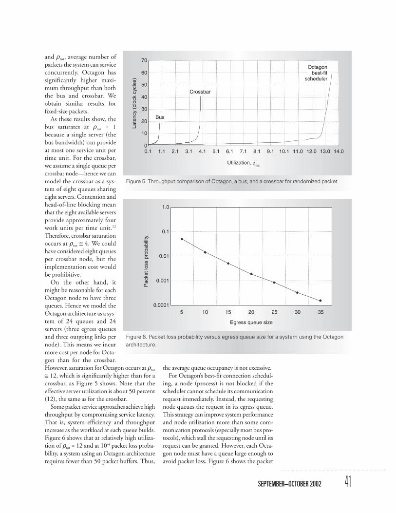
and ρtot, average number ofpackets the system can serviceconcurrently. Octagon hassignificantly higher maxi-mum throughput than boththe bus and crossbar. Weobtain similar results forfixed-size packets.
As these results show, thebus saturates at ρtot = 1because a single server (thebus bandwidth) can provideat most one service unit pertime unit. For the crossbar,we assume a single queue percrossbar node—hence we canmodel the crossbar as a sys-tem of eight queues sharingeight servers. Contention andhead-of-line blocking meanthat the eight available serversprovide approximately fourwork units per time unit.12
Therefore, crossbar saturationoccurs at ρtot ≅ 4. We couldhave considered eight queuesper crossbar node, but theimplementation cost wouldbe prohibitive.
On the other hand, itmight be reasonable for eachOctagon node to have threequeues. Hence we model theOctagon architecture as a sys-tem of 24 queues and 24servers (three egress queuesand three outgoing links pernode). This means we incurmore cost per node for Octa-gon than for the crossbar.However, saturation for Octagon occurs at ρtot
≅ 12, which is significantly higher than for acrossbar, as Figure 5 shows. Note that theeffective server utilization is about 50 percent(12), the same as for the crossbar.
Some packet service approaches achieve highthroughput by compromising service latency.That is, system efficiency and throughputincrease as the workload at each queue builds.Figure 6 shows that at relatively high utiliza-tion of ρtot = 12 and at 10-4 packet loss proba-bility, a system using an Octagon architecturerequires fewer than 50 packet buffers. Thus,
the average queue occupancy is not excessive.For Octagon’s best-fit connection schedul-
ing, a node (process) is not blocked if thescheduler cannot schedule its communicationrequest immediately. Instead, the requestingnode queues the request in its egress queue.This strategy can improve system performanceand node utilization more than some com-munication protocols (especially most bus pro-tocols), which stall the requesting node until itsrequest can be granted. However, each Octa-gon node must have a queue large enough toavoid packet loss. Figure 6 shows the packet
41SEPTEMBER–OCTOBER 2002
0
10
20
30
40
50
60
70
Utilization, ρtot
Late
ncy
(clo
ck c
ycle
s)
0.1 1.1 2.1 3.1 4.1 5.1 6.1 7.1 8.1 9.1 10.1 11.0 12.0 13.0 14.0
Octagonbest-fit
scheduler
Crossbar
Bus
Figure 5. Throughput comparison of Octagon, a bus, and a crossbar for randomized packet
1.0
0.1
0.01
0.001
0.0001
Pac
ket l
oss
prob
abili
ty
5 10 15 20
Egress queue size
25 30 35
Figure 6. Packet loss probability versus egress queue size for a system using the Octagonarchitecture.
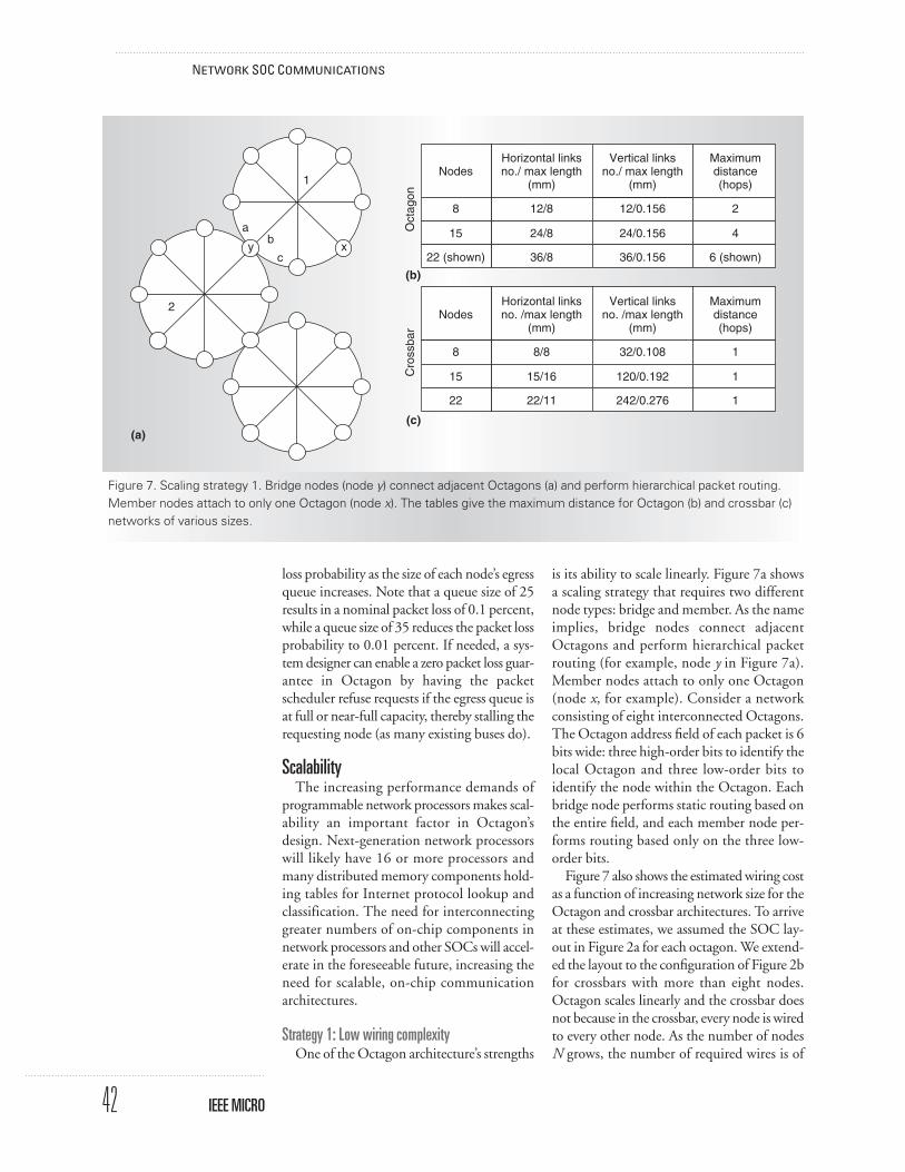
loss probability as the size of each node’s egressqueue increases. Note that a queue size of 25results in a nominal packet loss of 0.1 percent,while a queue size of 35 reduces the packet lossprobability to 0.01 percent. If needed, a sys-tem designer can enable a zero packet loss guar-antee in Octagon by having the packetscheduler refuse requests if the egress queue isat full or near-full capacity, thereby stalling therequesting node (as many existing buses do).
ScalabilityThe increasing performance demands of
programmable network processors makes scal-ability an important factor in Octagon’sdesign. Next-generation network processorswill likely have 16 or more processors andmany distributed memory components hold-ing tables for Internet protocol lookup andclassification. The need for interconnectinggreater numbers of on-chip components innetwork processors and other SOCs will accel-erate in the foreseeable future, increasing theneed for scalable, on-chip communicationarchitectures.
Strategy 1: Low wiring complexityOne of the Octagon architecture’s strengths
is its ability to scale linearly. Figure 7a showsa scaling strategy that requires two differentnode types: bridge and member. As the nameimplies, bridge nodes connect adjacentOctagons and perform hierarchical packetrouting (for example, node y in Figure 7a).Member nodes attach to only one Octagon(node x, for example). Consider a networkconsisting of eight interconnected Octagons.The Octagon address field of each packet is 6bits wide: three high-order bits to identify thelocal Octagon and three low-order bits toidentify the node within the Octagon. Eachbridge node performs static routing based onthe entire field, and each member node per-forms routing based only on the three low-order bits.
Figure 7 also shows the estimated wiring costas a function of increasing network size for theOctagon and crossbar architectures. To arriveat these estimates, we assumed the SOC lay-out in Figure 2a for each octagon. We extend-ed the layout to the configuration of Figure 2bfor crossbars with more than eight nodes.Octagon scales linearly and the crossbar doesnot because in the crossbar, every node is wiredto every other node. As the number of nodesN grows, the number of required wires is of
42
NETWORK SOC COMMUNICATIONS
IEEE MICRO
Oct
agon
2
1
ab
c
2
4
6 (shown)y x
NodesHorizontal linksno./ max length
(mm)
Vertical linksno./ max length
(mm)
12/0.156
24/0.156
36/0.156
12/8
24/8
36/8
8
15
22 (shown)
Maximumdistance(hops)
Cro
ssba
r
1
1
1
NodesHorizontal linksno. /max length
(mm)
Vertical linksno. /max length
(mm)
32/0.108
120/0.192
242/0.276
8/8
15/16
22/11
8
15
22
Maximumdistance(hops)
Figure 7. Scaling strategy 1. Bridge nodes (node y) connect adjacent Octagons (a) and perform hierarchical packet routing.Member nodes attach to only one Octagon (node x). The tables give the maximum distance for Octagon (b) and crossbar (c)networks of various sizes.
(a)
(b)
(c)
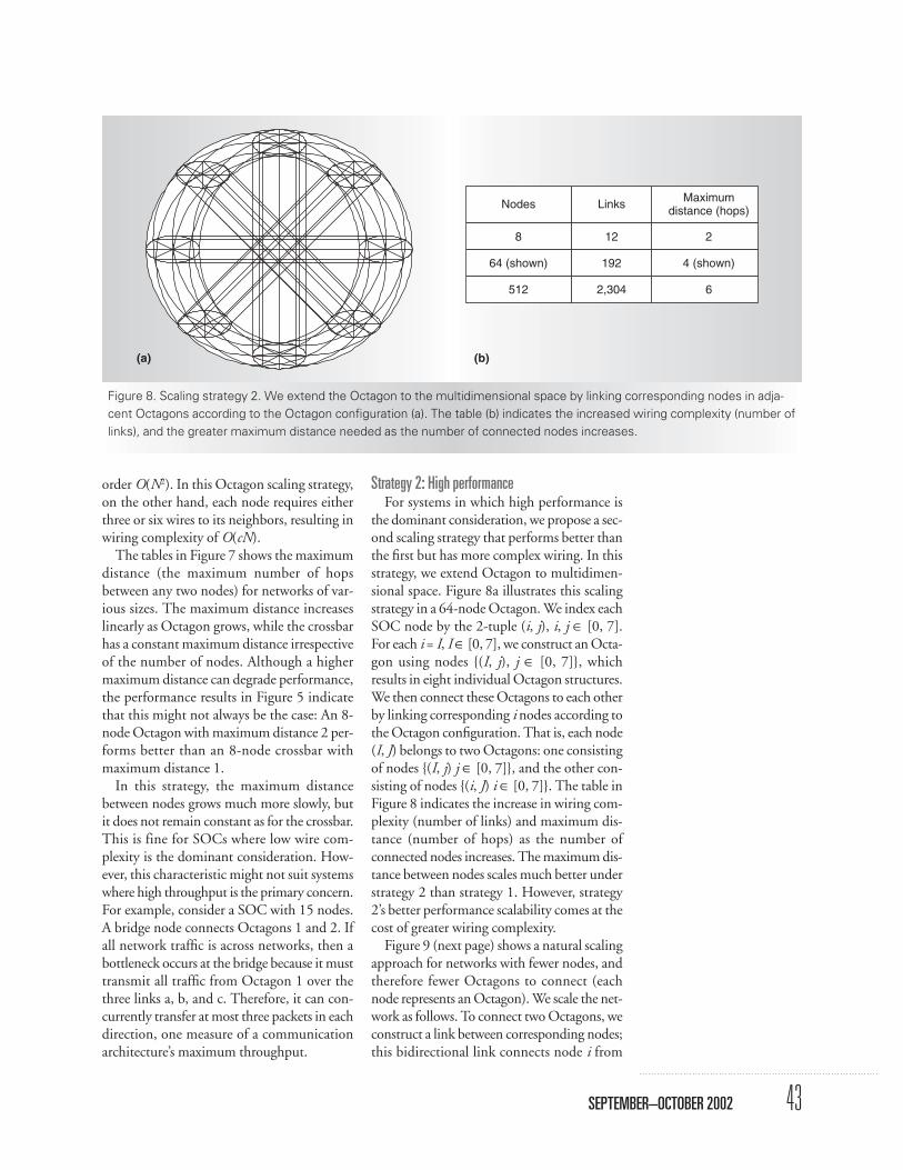
order O(N2). In this Octagon scaling strategy,on the other hand, each node requires eitherthree or six wires to its neighbors, resulting inwiring complexity of O(cN).
The tables in Figure 7 shows the maximumdistance (the maximum number of hopsbetween any two nodes) for networks of var-ious sizes. The maximum distance increaseslinearly as Octagon grows, while the crossbarhas a constant maximum distance irrespectiveof the number of nodes. Although a highermaximum distance can degrade performance,the performance results in Figure 5 indicatethat this might not always be the case: An 8-node Octagon with maximum distance 2 per-forms better than an 8-node crossbar withmaximum distance 1.
In this strategy, the maximum distancebetween nodes grows much more slowly, butit does not remain constant as for the crossbar.This is fine for SOCs where low wire com-plexity is the dominant consideration. How-ever, this characteristic might not suit systemswhere high throughput is the primary concern.For example, consider a SOC with 15 nodes.A bridge node connects Octagons 1 and 2. Ifall network traffic is across networks, then abottleneck occurs at the bridge because it musttransmit all traffic from Octagon 1 over thethree links a, b, and c. Therefore, it can con-currently transfer at most three packets in eachdirection, one measure of a communicationarchitecture’s maximum throughput.
Strategy 2: High performanceFor systems in which high performance is
the dominant consideration, we propose a sec-ond scaling strategy that performs better thanthe first but has more complex wiring. In thisstrategy, we extend Octagon to multidimen-sional space. Figure 8a illustrates this scalingstrategy in a 64-node Octagon. We index eachSOC node by the 2-tuple (i, j), i, j ∈ [0, 7].For each i = I, I ∈ [0, 7], we construct an Octa-gon using nodes {(I, j), j ∈ [0, 7]}, whichresults in eight individual Octagon structures.We then connect these Octagons to each otherby linking corresponding i nodes according tothe Octagon configuration. That is, each node(I, J) belongs to two Octagons: one consistingof nodes {(I, j) j ∈ [0, 7]}, and the other con-sisting of nodes {(i, J) i ∈ [0, 7]}. The table inFigure 8 indicates the increase in wiring com-plexity (number of links) and maximum dis-tance (number of hops) as the number ofconnected nodes increases. The maximum dis-tance between nodes scales much better understrategy 2 than strategy 1. However, strategy2’s better performance scalability comes at thecost of greater wiring complexity.
Figure 9 (next page) shows a natural scalingapproach for networks with fewer nodes, andtherefore fewer Octagons to connect (eachnode represents an Octagon). We scale the net-work as follows. To connect two Octagons, weconstruct a link between corresponding nodes;this bidirectional link connects node i from
43SEPTEMBER–OCTOBER 2002
Nodes
8
64 (shown)
512
Links
12
192
2,304
Maximumdistance (hops)
2
4 (shown)
6
Figure 8. Scaling strategy 2. We extend the Octagon to the multidimensional space by linking corresponding nodes in adja-cent Octagons according to the Octagon configuration (a). The table (b) indicates the increased wiring complexity (number oflinks), and the greater maximum distance needed as the number of connected nodes increases.
(a) (b)
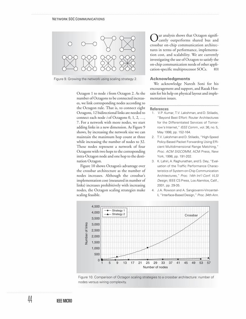
Octagon 1 to node i from Octagon 2. As thenumber of Octagons to be connected increas-es, we link corresponding nodes according tothe Octagon rule. That is, to connect eightOctagons, 12 bidirectional links are needed toconnect each node i of Octagons 0, 1, 2, …,7. For a network with more nodes, we startadding links in a new dimension. As Figure 9shows, by increasing the network size we canmaintain the maximum hop count at threewhile increasing the number of nodes to 32.These nodes represent a network of fourOctagons with two hops to the correspondingintra-Octagon node and one hop to the desti-nation Octagon.
Figure 10 shows Octagon’s advantage overthe crossbar architecture as the number ofnodes increases. Although the crossbar’simplementation cost (measured in number oflinks) increases prohibitively with increasingnodes, the Octagon scaling strategies makescaling feasible.
Our analysis shows that Octagon signifi-cantly outperforms shared bus and
crossbar on-chip communication architec-tures in terms of performance, implementa-tion cost, and scalability. We are currentlyinvestigating the use of Octagon to satisfy theon-chip communication needs of other appli-cation-specific multiprocessor SOCs. MICRO
AcknowledgmentsWe acknowledge Naresh Soni for his
encouragement and support, and Razak Hos-sain for his help on physical layout and imple-mentation issues.
References1. V.P. Kumar, T.V. Lakshman, and D. Stiliadis,
“Beyond Best Effort: Router Architecturesfor the Differentiated Services of Tomor-row’s Internet,” IEEE Comm., vol. 36, no. 5,May 1998, pp. 152-164.
2. T.V. Lakshman and D. Stiliadis, “High-SpeedPolicy-Based Packet Forwarding Using Effi-cient Multidimensional Range Matching,”Proc. ACM SIGCOMM, ACM Press, NewYork, 1998, pp. 191-202.
3. K. Lahiri, A. Raghunathan, and S. Dey, “Eval-uation of the Traffic Performance Charac-teristics of System-on-Chip CommunicationArchitectures,” Proc. 14th Int’l Conf. VLSIDesign, IEEE CS Press, Los Alamitos, Calif.,2001, pp. 29-35.
4. J.A. Rowson and A. Sangiovanni-Vincentel-li, “Interface-Based Design,” Proc. 34th Ann.
44
NETWORK SOC COMMUNICATIONS
IEEE MICRO
Figure 9. Growing the network using scaling strategy 2.
1 5 9 13 17 21 25 29 33 37 41 45 49 5753Number of nodes
4,500
4,000
3,500
3,000
2,500
2,000
1,500
1,000
500
0
Num
ber
of li
nks
Crossbar
Strategy 1Strategy 2
Figure 10. Comparison of Octagon scaling strategies to a crossbar architecture: number ofnodes versus wiring complexity.

Design Automation Conf., ACM Press, NewYork, 1997, pp. 178-183.
5. R.B. Ortega and G. Borriello, “Communica-tion Synthesis for Distributed EmbeddedSystems,” Proc. Int’l Conf. Computer-AidedDesign (ICCAD 98), IEEE CS Press, LosAlamitos, Calif., 1998, pp. 437-444.
6. M. Gasteier and M. Glesner, “Bus-BasedCommunication Synthesis on System Level,”ACM Trans. Design Automation ElectronicSystems, vol. 4, no. 1, Jan. 1999, pp. 1-11.
7. K. Lahiri, A. Raghunathan, and S. Dey,“Communication Architecture Tuners: AMethodology for the Design of High-Perfor-mance Communication Architectures forSystem-on-Chips,” Proc. 37th DesignAutomation Conf., ACM Press, New York,2000, pp. 513-518.
8. K. Lahiri, A. Raghunathan, and S. Dey, “Effi-cient Exploration of the SOC CommunicationArchitecture Design Space,” Proc. Int’l Conf.Computer-Aided Design (ICCAD 00), IEEE CSPress, Los Alamitos, Calif., 2000, pp. 424-430.
9. Sonics Integration Architecture, www.sonicsinc.com.
10. D. Flynn, “AMBA: Enabling Reusable On-Chip Designs,” IEEE Micro, vol. 7, no. 4,July-Aug. 1997, pp. 20-27.
11. A. Charlesworth, “The Sun Fireplane Inter-connect,” IEEE Micro, vol. 22, no. 1, Jan.-Feb. 2002, pp. 36-45.
12. J. Chen and T. Stern, “Throughput Analysis,Optimal Buffer Allocation, and Traffic Imbal-ance Study of a Generic Nonblocking Pack-et Switch,” IEEE J. Selected Areas inComm., vol. 9, no. 3, Apr. 1991, pp. 439-449.
13. D. Gross and C. Harris, Fundamentals ofQueueing Theory, 3rd ed., John Wiley &Sons, New York, 1998, pp. 297-300.
Faraydon Karim is an ST Fellow at STMicro-electronics’ Advanced System Technology,Advanced Computing Lab in La Jolla, Cali-fornia. His research interests include comput-er and embedded system architecture. Karimhas a PhD in computer engineering from LaSalle University. He is a member of the IEEE.
Anh Nguyen is a research engineer at theSTMicroelectronics Advanced Systems Tech-nology, Advanced Computing Lab in La Jolla,California. His research interests include per-formance analysis, resource allocation, and
algorithm development. Nguyen has a PhDin electrical engineering from the Universityof California, Los Angeles. He is a member ofthe IEEE.
Sujit Dey is a professor in the Electrical andComputer Engineering Department at theUniversity of California, San Diego. Hisresearch interests include configurable plat-forms consisting of adaptive wireless proto-cols and algorithms, and deep-submicronadaptive SOCs for next-generation wirelessappliances and network infrastructure devices.Dey has a PhD in computer science fromDuke University. He is a member of the IEEE.
Direct questions and comments to Faray-don Karim at STMicroelectronics, AdvancedSystem Technology, San Diego, CA 92121;[email protected].
For further information on this or any othercomputing topic, visit our Digital Library athttp://computer.org/publications/dlib.
45SEPTEMBER–OCTOBER 2002
Join a community that targets your discipline.
In our Technical Committees, you’re in good company.
computer.org/TCsignup/
Looking for a community targeted to yourarea of expertise? Computer SocietyTechnical Committees explore a variety
of computing niches and provide forums fordialogue among peers. These groups influenceour standards development and offer leadingconferences in their fields.
JOIN A THINKTANK