basic networking concepts
TRANSCRIPT
Basic Networking Concepts
1. Introduction
2. Protocols
3. Protocol Layers
4. Network Interconnection/Internet
1
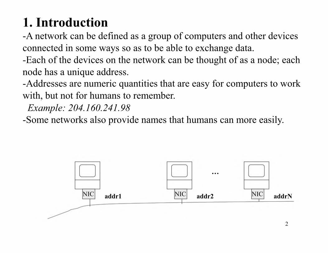
1. Introduction-A network can be defined as a group of computers and other devices
connected in some ways so as to be able to exchange data.
-Each of the devices on the network can be thought of as a node; each
node has a unique address.
-Addresses are numeric quantities that are easy for computers to work
with, but not for humans to remember.
Example: 204.160.241.98
-Some networks also provide names that humans can more easily.
…
NIC addr1 NIC addr2 NIC addrN
2
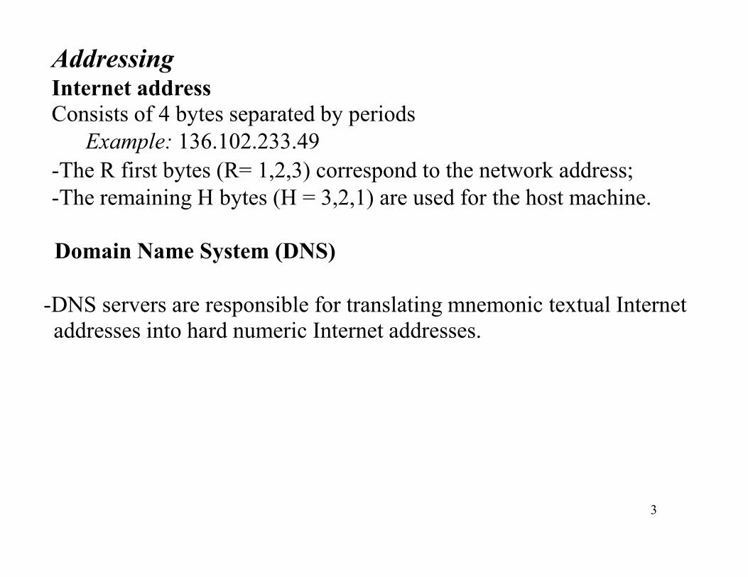
AddressingInternet address
Consists of 4 bytes separated by periods
Example: 136.102.233.49
-The R first bytes (R= 1,2,3) correspond to the network address;
-The remaining H bytes (H = 3,2,1) are used for the host machine.
Domain Name System (DNS)
-DNS servers are responsible for translating mnemonic textual Internet
3
addresses into hard numeric Internet addresses.
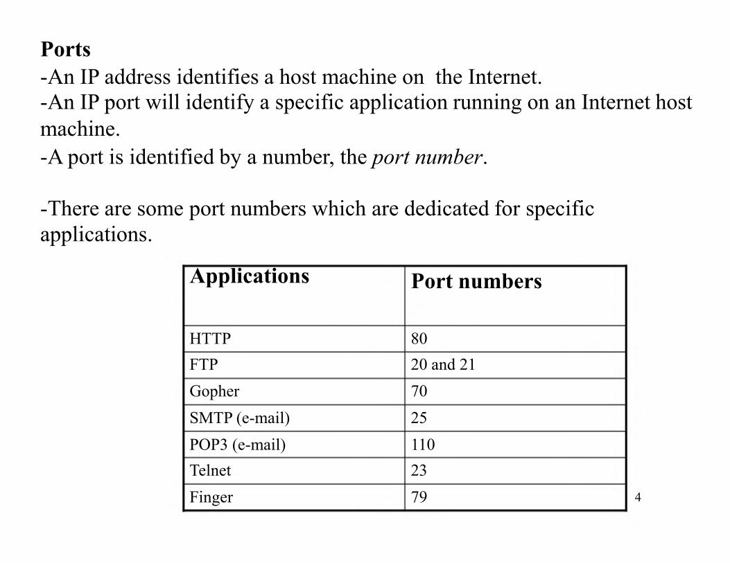
Ports
-An IP address identifies a host machine on the Internet.
-An IP port will identify a specific application running on an Internet host
machine.
-A port is identified by a number, the port number.
-There are some port numbers which are dedicated for specific
applications.
Applications Port numbersApplications Port numbers
HTTP 80
FTP 20 and 21
Gopher 70
SMTP (e-mail) 25
POP3 (e-mail) 110
Telnet 23
Finger 79 4
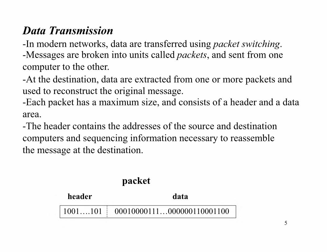
Data Transmission-In modern networks, data are transferred using packet switching.-Messages are broken into units called packets, and sent from one
computer to the other.
-At the destination, data are extracted from one or more packets and
used to reconstruct the original message.-Each packet has a maximum size, and consists of a header and a data
area.
-The header contains the addresses of the source and destination-The header contains the addresses of the source and destination
computers and sequencing information necessary to reassemble
the message at the destination.
packet
header data
1001….101 00010000111…000000110001100
5
Types of NetworksThere are two principle kinds of networks: Wide Area Networks
(WANs) and Local Area Networks (LANs).
WANs
-Cover cities, countries, and continents.
-Based on packet switching technology-Examples of WAN technology: Asynchronous Transfer Mode (ATM),
Integrated Services Digital Network (ISDN)
LANsLANs
-Cover buildings or a set of closely related buildings.-Examples of LAN technology: Ethernet, Token Ring, and Fibber
Distributed Data Interconnect (FDDI).
Ethernet LANs: based on a bus topology and broadcast communication
Token ring LANs: based on ring topology
FDDI LANs: use optical fibbers and an improved token ring mechanism
based on two rings flowing in opposite directions.
6
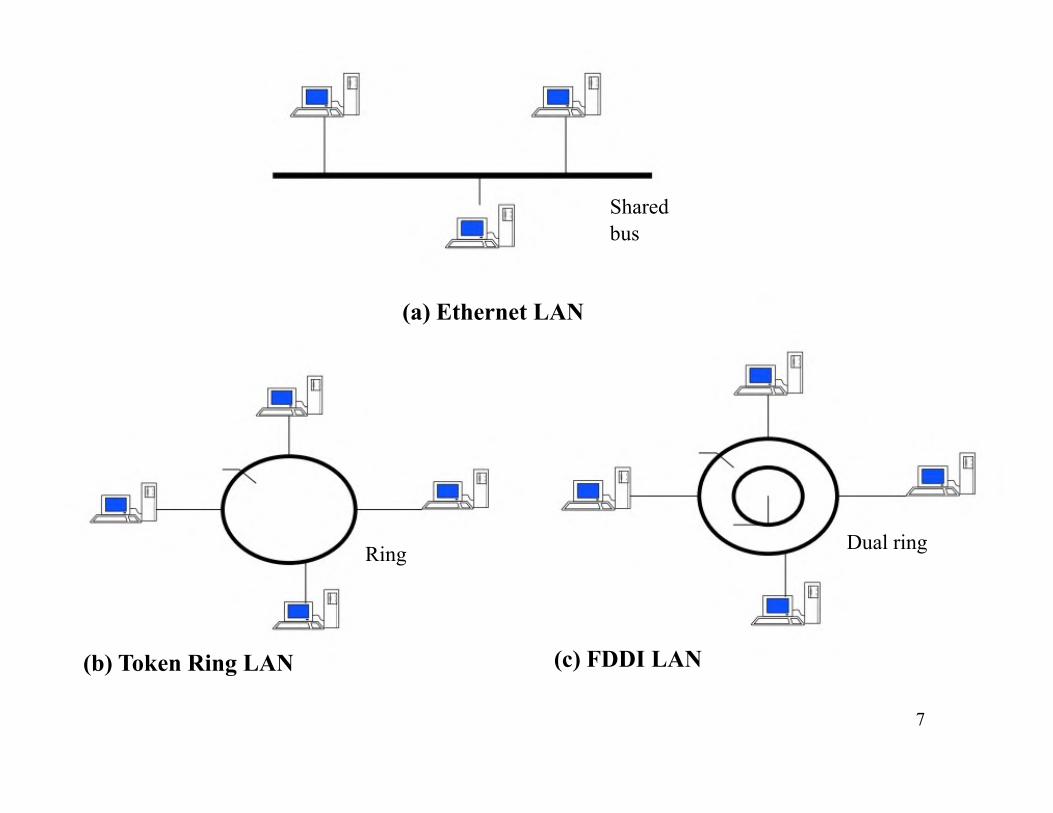
Shared
bus
(a) Ethernet LAN
(b) Token Ring LAN
Ring
(c) FDDI LAN
Dual ring
7
Interconnection
-Networks of low capacity may be connected together via a backbonenetwork which is a network of high capacity such as a FDDI network, a
WAN network etc.
-Networks interconnection is achieved using one or several of the
following devices:
→Bridge: a computer or device that links two similar LANs based on
the same protocol.
→ Router: a communication computer that connects different types of
networks using different protocols.
→ B-router or Bridge/Router: a single device that combines both the
functions of bridge and router.
→ Gateway: a network device that connects two different systems, using
direct and systematic translation between protocols.
9
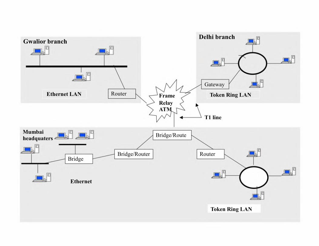
Delhi branchGwalior branch
Gateway
Ethernet LAN Router Frame Token Ring LAN
Relay
ATM
T1 line
Mumbai
headquaters
Bridge
Ethernet
Bridge/Route
Bridge/Router Router
Token Ring LAN
Network Topology Diagram
The network topology diagram requires the following description
about the network :
-Geographical locations of the different components or subnets
involved in the network.involved in the network.
-Description of the LAN topology
-Description of the WAN topology
-Description of the network connectors such as routers, bridges,
repeaters, and gateways.
11
2. Protocols-Define the rules that govern the communications between two
computers connected to the network.
-Roles: addressing and routing of messages, error detection and
recovery, sequence and flow controls etc.
-A protocol consists of the syntax, which defines the kinds
and formats of the messages exchanged, and the semantic, whichand formats of the messages exchanged, and the semantic, which
specifies the action taken by each entity when specific events occur.
Example: HTTP protocol for communication between web browsers
and servers.
12
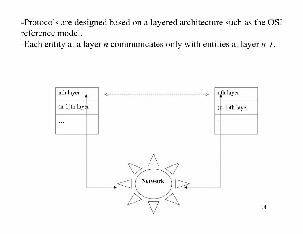
-Protocols are designed based on a layered architecture such as the OSI
reference model.
-Each entity at a layer n communicates only with entities at layer n-1.
nth layer
(n-1)th layer
nth layer
(n-1)th layer
…
Network
…
14
3. Protocol Layers
The OSI (Open Systems Interconnection) Data Model-ISO standard for computer networks design and functioning.
-Involves at least 7 layers, each playing a specific role when
applications are communicating over the net.
-During the sending process, each layer (from top to down) will add-During the sending process, each layer (from top to down) will add
a specific header to the raw data.
-At the reception, headers are eliminated conversely until the data
arrived to the receiving application.
15
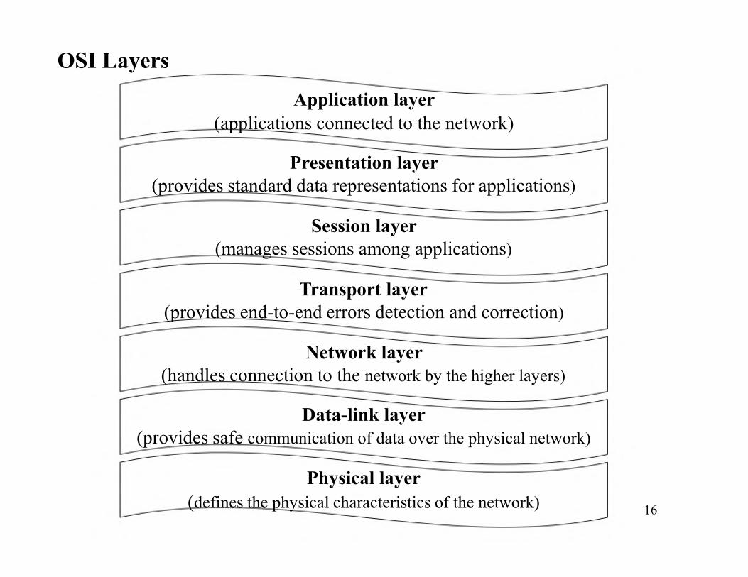
OSI Layers
Application layer
(applications connected to the network)
Presentation layer
(provides standard data representations for applications)
Session layer
(manages sessions among applications)
Transport layerTransport layer
(provides end-to-end errors detection and correction)
Network layer
(handles connection to the network by the higher layers)
Data-link layer
(provides safe communication of data over the physical network)
Physical layer
(defines the physical characteristics of the network)16
Physical layer: ensures a safe and efficient travel of data; consists of
electronic circuits for data transmission etc.
Data link layer: in charge of data encapsulation under the form of
packets and their interpretation at the physical layer.
Network layer: in charge of packets transmission from a source A to a
destination B.
Transport layer: in charge of the delivery of packets from a source ATransport layer: in charge of the delivery of packets from a source A
to a destination B
Session layer: in charge of the management of network access.
Presentation layer: determines the format of the data transmitted to
applications, data compressing/decompressing, encrypting etc.
Application layer: contains the applications which are used by theend-user, such as Java, Word etc. 17
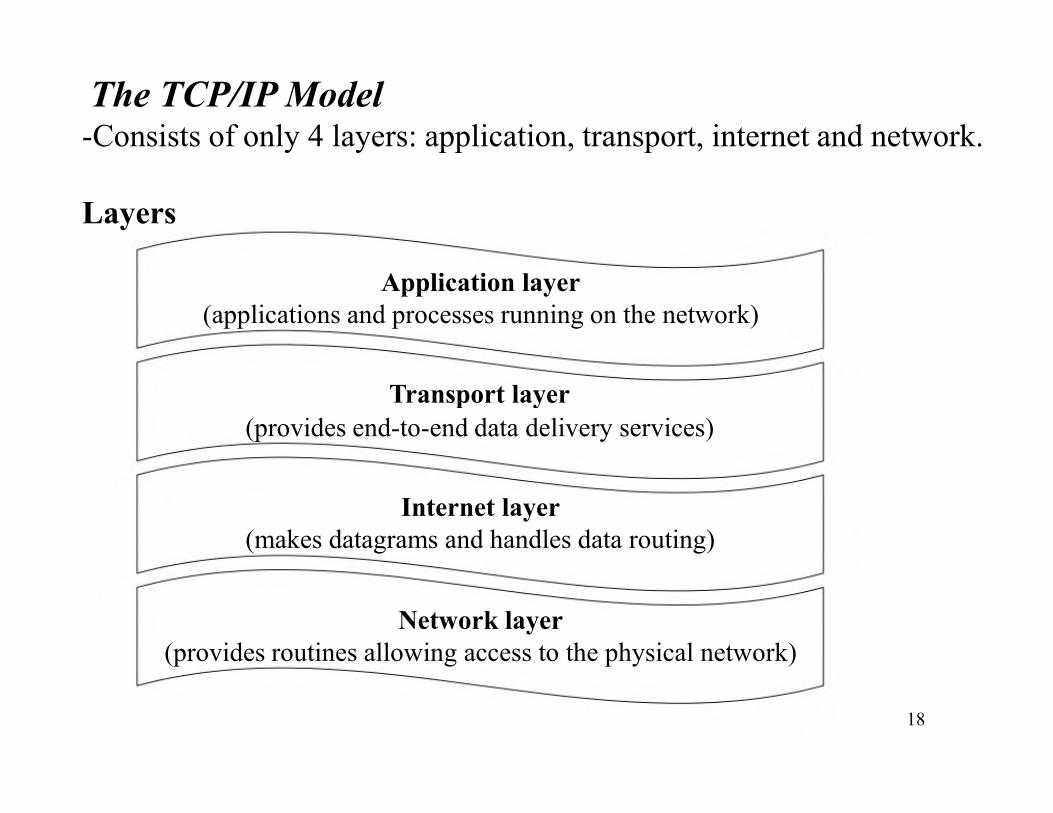
The TCP/IP Model-Consists of only 4 layers: application, transport, internet and network.
Layers
Application layer
(applications and processes running on the network)
Transport layerTransport layer
(provides end-to-end data delivery services)
Internet layer
(makes datagrams and handles data routing)
Network layer
(provides routines allowing access to the physical network)
18
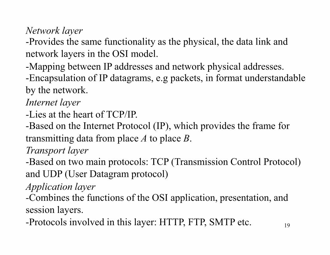
Network layer-Provides the same functionality as the physical, the data link and
network layers in the OSI model.
-Mapping between IP addresses and network physical addresses.
-Encapsulation of IP datagrams, e.g packets, in format understandable
by the network.
Internet layer
-Lies at the heart of TCP/IP.-Based on the Internet Protocol (IP), which provides the frame for-Based on the Internet Protocol (IP), which provides the frame for
transmitting data from place A to place B.
Transport layer
-Based on two main protocols: TCP (Transmission Control Protocol)
and UDP (User Datagram protocol)
Application layer-Combines the functions of the OSI application, presentation, and
session layers.
-Protocols involved in this layer: HTTP, FTP, SMTP etc. 19
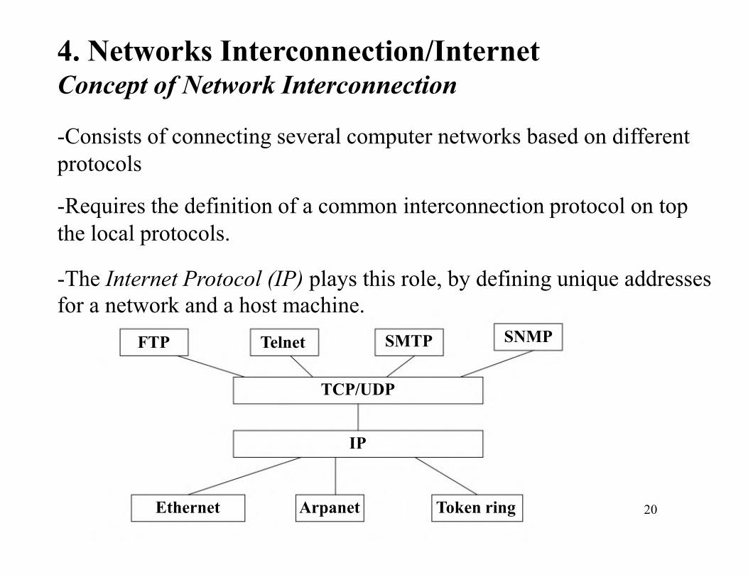
4. Networks Interconnection/InternetConcept of Network Interconnection
-Consists of connecting several computer networks based on different
protocols
-Requires the definition of a common interconnection protocol on top
the local protocols.
-The Internet Protocol (IP) plays this role, by defining unique addresses-The Internet Protocol (IP) plays this role, by defining unique addresses
for a network and a host machine.
FTP Telnet SNMPSMTP
TCP/UDP
IP
Ethernet Arpanet Token ring 20
Internet Protocol (IP)Overview
-The IP protocol provides two main functionality:
→Decomposition of the initial information flow into packets of
standardized size, and reassembling at the destination.
→Routing of a packet through successive networks, from the source
machine to the destination identified by its IP address.
-Transmitted packets are not guaranteed to be delivered (datagram
protocol).protocol).
-The IP protocol does not request for connection (connectionless)
before sending data and does not make any error detection.
Functions
-Decompose the initial data (to be sent) into datagrams.-Each datagram will have a header including, the IP address and the
port number of the destination.
-Datagrams are then sent to selected gateways, e.g IP routers, connected
at the same time to the local network and to an IP service provider22
network.
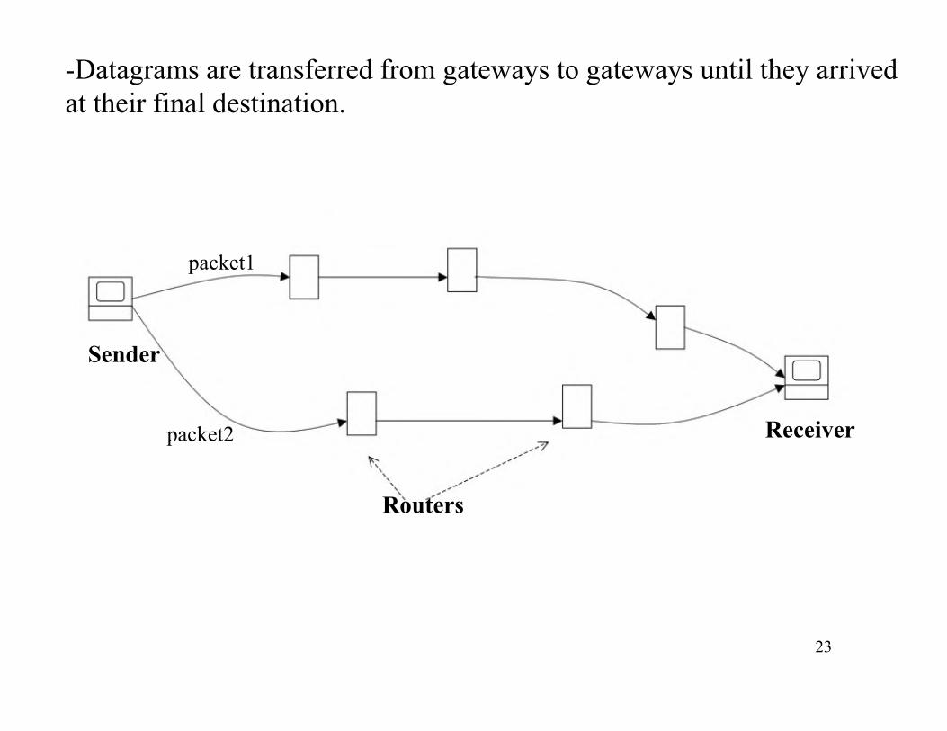
-Datagrams are transferred from gateways to gateways until they arrived
at their final destination.
packet1
SenderSender
packet2 Receiver
Routers
23
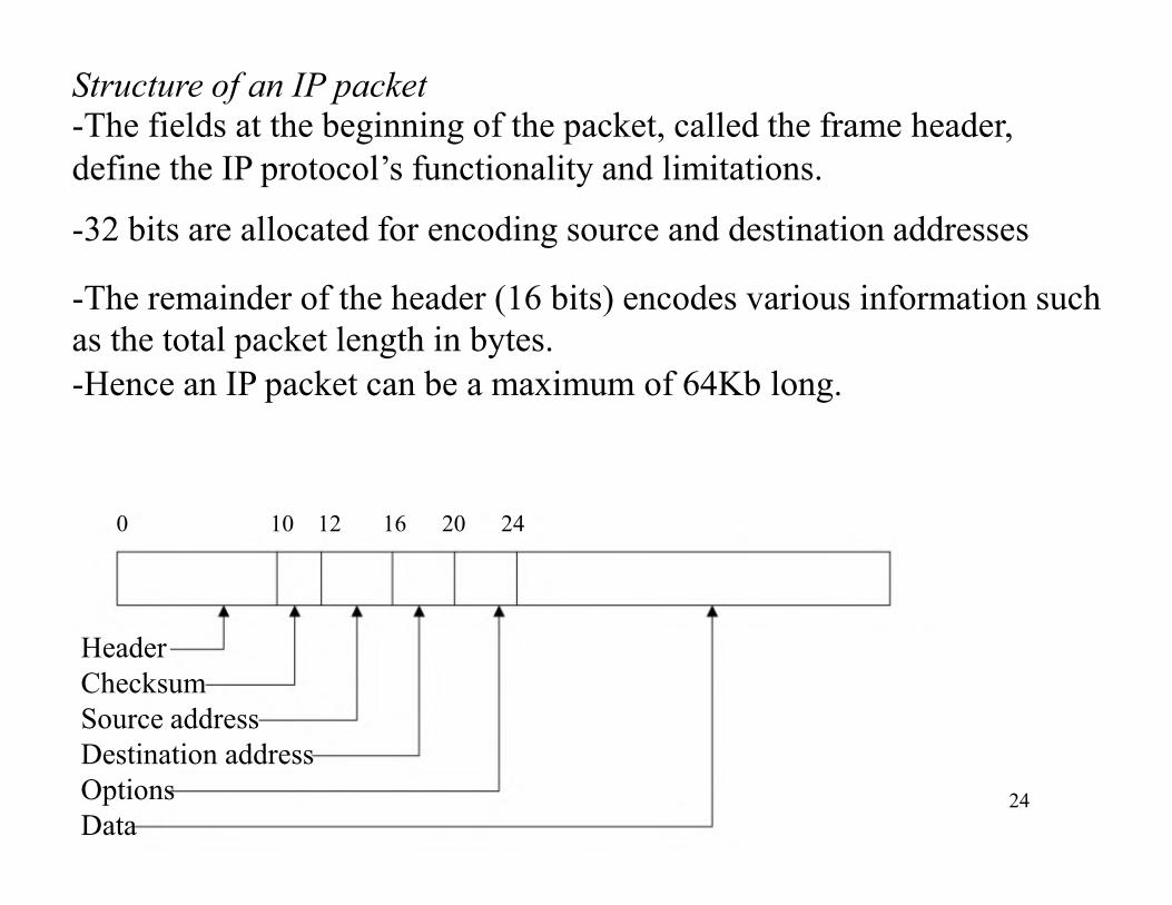
Structure of an IP packet-The fields at the beginning of the packet, called the frame header,
define the IP protocol’s functionality and limitations.
-32 bits are allocated for encoding source and destination addresses
-The remainder of the header (16 bits) encodes various information such
as the total packet length in bytes.
-Hence an IP packet can be a maximum of 64Kb long.
0 10 12 16 20 24
Header
Checksum
Source address
Destination address
Options
Data24

Transmission Control Protocol (TCP)Overview-TCP provides by using IP packets a basic service that does guarantee
safe delivery:
→error detection
→safe data transmission
→assurance that data are received in the correct order-Before sending data, TCP requires that the computers communicating
establish a connection (connection-oriented protocol).establish a connection (connection-oriented protocol).
Client
SYN_ACK
DATA
ACK
FIN
TCP
SYN
ACK
DATA
FIN
DATA
ACK
Server
25
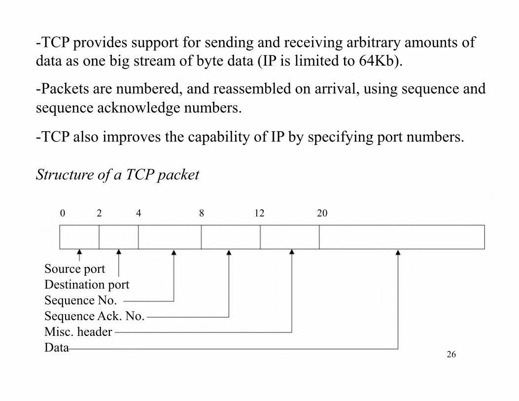
-TCP provides support for sending and receiving arbitrary amounts of
data as one big stream of byte data (IP is limited to 64Kb).
-Packets are numbered, and reassembled on arrival, using sequence and
sequence acknowledge numbers.
-TCP also improves the capability of IP by specifying port numbers.
Structure of a TCP packet
0 2 4 8 12 20
Source port
Destination port
Sequence No.
Sequence Ack. No.
Misc. header
Data26
User Datagram Protocol (UDP)
Overview
-Datagram protocol also built on top of IP.
-Has the same packet-size limit (64Kb) as IP, but allows for port
number specification.
-Provides also 65,536 different ports.-Hence, every machine has two sets of 65,536 ports: one for TCP and the
other for UDP.
-Connectionless protocol, without any error detection facility.-Provides only support for data transmission from one end to the other,-Provides only support for data transmission from one end to the other,
without any further verification.
-The main interest of UDP is that since it does not make further
verification, it is very fast.
-Useful for sending small size data in a repetitive way such as time
information.
27