electrical interconnect solutions catalogue cleevetech.com
TRANSCRIPT

Electrical
Interconnect
Solutions
Catalogue
cleevetech.com
C L E E V E T E C H N O L O G Y I N T E R N A T I O N A L

0-5introduction | CTI |
Personal Information (if lost please return to:)
Name: _________________________________________________________________________________________________
Address: _________________________________________________________________________ Apt.: __________________
Home Telephone: ___________________________________________ Home Facsmilie: _________________________________
Company Name: __________________________________________________________________________________________
Address: _________________________________________________________________________ Apt.: __________________
Work Telephone: __________________________________ Ext.: ___________ Work Facsmilie: _____________________________
Mobile Number: ___________________________________________ E-Mail: _________________________________________
Cleeve Technology International (CTI) is a high-tech, innovative company that has developed a substantial profile in the electrical inter-
connect sector of the aerospace and military industries worldwide.
CTI started into business in Oshawa, Ontario, Canada in May of 1998. The company began representing foreign manufacturers of
electrical interconnect parts and components for military and aerospace applications in Canada. In 2005, in order to accommodate the
company’s growth, we moved to our own custom built property on Colonel Sam Drive. Our business continues to expand as the
company continues to focus on providing solutions to customers’ needs and solving difficult problems.
Recognizing the benefits of expanding our operations in the United Kingdom and Europe, we launched into the United Kingdom market
and captured one of the largest contracts for supplying electrical interconnect components to the British Military in support of the
Bowman Communication System Program. CTI now has two locations in the United Kingdom, a shipping and receiving warehouse in
Wigan and a sales centre near Cheltenham. Most recently, CTI has set up business operations in Germany, Holland, Australia and the
United States. CTI has a Global MRP system which allows us full visibility of our world-wide inventories.
CTI has acquired, and continues to acquire, complimentary companies and capabilities allowing us to expand into new markets such as
rail and mass transit, medical, shipboard and marine. As a result, CTI continues to provide products and solutions with better lead times
than our competitors securing our position as a leader in our field.
Even with the company’s international success, CTI continues to foster close relationships within the communities in which we live. The
company is an active participant in Aviation Exhibitions and other local trade shows and recruits graduates and co-op students from local
colleges and high schools. In addition, the company supports local charities, sports organizations, cultural organizations and fosters the
growth of its employees through worldwide experiences.
C l e e v e Te c h n o l o g y I n t e r n a t i o n a l[ ]Innovative. Creative. Resourceful. Challenge us today!
0-1introduction | CTI |

0-2 | CTI | www.cleevetech.com
Our Mission:
Cleeve Technology International (CTI) is a group of companies that together offer a
turnkey, supply and support solution for customers’ electrical interconnect requirements.
CTI empowers its employees to offer quality solutions to customers electrical interconnect
problems and this enables our customers to mitigate risk and focus on their own core
interests and capabilities.
CTI will go above and beyond to exceed our customer and employee expectations through
continuous improvement.
Regards,
Paul Church, President
q u a l i t y s o l u t i o n saccording to the customer’s requirements[ ]

0-3introduction | CTI |
Table of ContentsSection Reference Page(s)
1 Wire and Cable 1-10
2 Connectors, Contacts and Protection Caps 2-30
3 Backshells, Adaptors and Accessories 3-42
4 Heat Shrink Molded Parts 4-56
5 Tubing, Solder Sleeves and Idents. 5-64
6 Kits, Assemblies, Sub-Assemblies and Feedthroughs 6-84
7 Cable Ties and Cable Management Products 7-90
8 Circuit Protection and Control 8-110
9 Tooling and Equipment 9-116
10 Technical Data and Specifications 10-121
For further information please contact us at:
Cleeve Technology International Headquarters
716 Colonel Sam Drive, Oshawa, Ontario, Canada L1H 7Y2
Tel: 001-905-579-9502
Fax: 001-905-579-9991
Email: [email protected]
Web: cleevetech.com

0-4 | CTI | www.cleevetech.com
CTI’s strength lies in a highly focused engineering approach to solving customers’ problems.
In addition to off-the-shelf components such as wire, cable, connectors, accessories and
circuit protection devices, we supply completely wired and tested systems to meet specific
project requirements. From standard MIL-spec qualified parts and ‘build to print’ assemblies
through to tested alternatives to sophisticated systems, we have the solution.
We are a high-tech, innovative, international company that has developed a substantial
profile in the electrical interconnect sector of the aerospace and military industry worldwide.
CTI has earned a reputation for taking the design and supply of products above and beyond
our customers’ expectations.
The company’s products and capabilities allow us to support the integration and supply of
electrical interconnect components and assemblies used in an electrical harness
system, panel or box that needs to operate in a harsh environment. Since the company takes
a ‘systems approach’ to design, development, qualification, supply and follow-up on product
support, it allows us to ensure compatibility of many of the products used in a high perform-
ance electrical system, panel or enclosure resulting in very high customer satisfaction. This has
allowed us to grow our business in new markets such as the rail and mass transit, medical,
shipboard and marine, and several other markets where performance in harsh environments
is critical.
CTI has invested in material management software that allows us to service our
customers with detailed reports related to performance and quality. Coupled with the com-
pany’s knowledge of the compatibility of products, CTI provides its customers with access to
a unique market of electrical interconnect components that would not normally be available.
CTI continues to provide better quality products with better lead times than our competitors
securing our position as a leader in our field.
CTI has always been focused on a team approach with our customers, suppliers and staff.
This team approach allows us to develop and maintain strong working relationships and
will ensure the future growth and success of CTI and the customers that we serve.
i n n o v a t i o n[ ]providing solutions to customers’ needs

Research and Development: CTI invests heavily in the development of new products and solutions to solve electrical
interconnect problems and to find solutions for special applications.
Application Technology: Our know-how is characterized by high quality yet economic solutions. We develop special products
according to the customer’s requirements by adapting the material to the corresponding application.
Production: The CTI group of companies is able to build to print, or to offer improvements to existing designs through to newly
engineered solutions.
Crosslinking: The molecular crosslinking of many of our materials intensifies the main properties:
- Optimization of shrinking capacity
- Increase of continuous operation temperature
- Improvement of electrical and mechanical resistance
- Improvement of chemical resistance
Quality Assurance: In accordance with ISO standards, we go above and beyond to demonstrate our commitment to quality.
Cutting and Printing: We offer custom and value added solutions in the field of cutting and marking of wire, tubing and sleeves:
- Cut lengths according to customer request- Marking of sleeves ordered on spools or in cut lengths according to customer’s request- Non-standard delivery units on special request
Logistics: On the basis of an efficient material management system our well-equipped and computer-assisted warehouses ensures
reliable and on time delivery.
An ISO9001:2000 Company: Quality assurance plays an important role in all projects. All materials will be controlled in
accordance to standardized procedures and the quality plan developed specifically for materials used in an electrical interconnect
system or harnessing system.
Control of Purchases: CTI will supply only qualified products from suppliers approved by CTI. The CTI quality group maintains and
issues a company approved suppliers list.
Outgoing Inspection: Shipping documents, test reports and the certificate of compliance are verified by the inspector for
correctness and conformity to the customer’s purchase order. The parts will be shipped in appropriate packaging with all the
documentation enclosed required by the applicable purchase order.
0-5introduction | CTI |

An Introduction to our Products and Services: CTI’s supply
and support products such as wire and cable, connectors, contacts,
backshells, heat shrinkable tubing and heat shrinkable molded parts
are used extensively in the military, aerospace and industrial
industries.
Our products and capabilities allow us to support the integration and
supply of electrical interconnect components, sub-assemblies and wired
and tested harness assemblies to meet specific program requirements.
Since we take a ‘systems approach’ to design, development, qualification,
supply and follow up on product support, it allows us to ensure compat-
ibility of many of the products used in an electrical harness system, panel
or box.
CTI and our manufacturing partners are approved suppliers to most
industries around the world. We are a privately owned Canadian com-
pany centrally located east of Toronto in Oshawa, Ontario. We are con-
fident we can provide qualified and cost effective solutions, products,
and assemblies for your applications and requirements.
CTI Experience: CTI has been involved in the support of the Military
and Aerospace industries for many years, and in most instances from
the risk reduction phase through to the completion of projects. CTI has
supplied much of the material used by harness contractors and also
supplies technical and engineering support when required.
CTI has added additional manufacturing companies to its supply base
over the past years and works closely with our customer’s engineering
staff to ensure only compliant material options are presented and
approved.
CTI has also developed controlled kits of materials specifically for those
industries as required for harness assemblies in order to ensure total
compliance, compatibility of material, configuration management and
reduced costs.
c o m p a t i b i l i t ymaterials, installation, training and ongoing support[ ]
Product Support
Technical Information
Manufacturing Warehouse
0-6 | CTI | www.cleevetech.com

Cleeve Technology International: Electrical Interconnect Solutions for High Performance Harnesses and Cable Assemblies
CTI has the worlds best suppliers at their disposal when it comes to design and problem-solving experience with
an unparalleled portfolio of products. The proven quality of support of our supply partners is matched
only by our own ongoing commitment to invest in new technologies to help meet your ‘next-generation’ systems
performance and commercial goals.
CTI is one of the largest distributors and material facilitators supporting the military and aerospace markets.
We can supply cables and material for your electrical harnesses used on existing requirements, or work with you
to develop alternatives or ‘next-generation’ solutions. We support from design prototype to serial production
and have an excellent engineering capability and extensive warehouse and stocking locations around the world.
CTI should be your first choice to contact for harnessing products including wire and cables, connectors,
accessories and all other interconnect parts.
Custom Harness Systems and Cable Connector Assemblies. Custom harnesses built to your
drawings and specifications are available. Pre-tested, factory-built harnesses provide quick, easy installation and
eliminate unnecessary splices and connectors reducing cost and increasing system reliability. Our product groups
also contain an extensive array of compatible components as follows:
• Harness systems and cable assemblies
• Multicore cables, made to customer specifications
• EMI/EMP Screening, optimized with shield termination systems
• Wire and cables, ruggedized for military applications
• Connectors and back shells according to industrial and military requirements
• Zero-halogen cables and components for marine applications
• Heat shrink materials with high performance
• Identifications systems including computerized print service
• Harness design software
• Engineering service and prototypes
• Serial manufacturing to numerous military and industrial standards
“ ”CTI’s expertise in the design and fabrication of complete wiring harnesses, coaxial cable and ribbon cable
assemblies helps us develop the right cable harnessing and custom solutions you require. CTI is the leading
supplier of electrical interconnect systems for military vehicles, aerospace, marine and industrial applications.
0-7introduction | CTI |
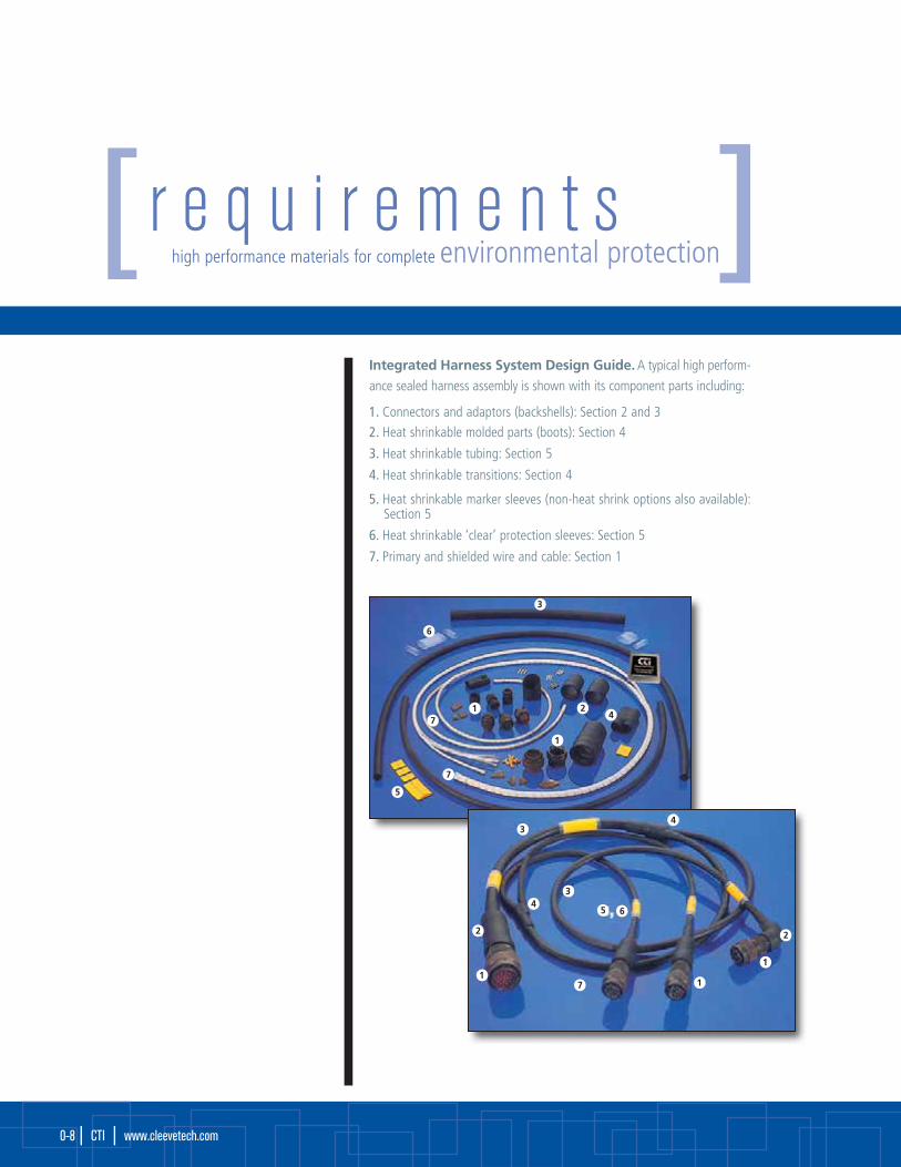
Integrated Harness System Design Guide. A typical high perform-
ance sealed harness assembly is shown with its component parts including:
1. Connectors and adaptors (backshells): Section 2 and 32. Heat shrinkable molded parts (boots): Section 4
3. Heat shrinkable tubing: Section 5
4. Heat shrinkable transitions: Section 4
5. Heat shrinkable marker sleeves (non-heat shrink options also available):Section 5
6. Heat shrinkable ‘clear’ protection sleeves: Section 5
7. Primary and shielded wire and cable: Section 1
r e q u i r e m e n t shigh performance materials for complete environmental protection[ ]
1
1
3
6
42
7
7
5
6
1
1
3
3
2
7
5
1
4
4
2
0-8 | CTI | www.cleevetech.com

Also available:• A wide range of termination devices for shield terminations and primary wire interconnection;• A selection of electrical shielding options including braids and termination devices;• Multi-conductor cables designed to meet your specific requirements;• Specialty high performance adhesives for complete environmental sealing (also pre-coated to the inside of the molded parts for ease
of assembly).
Innovative. Creative.Resourceful.
Challenge us today!
0-9introduction | CTI |

Electrical InterconnectionWire and cables that are small, lightweight and tough:
CTI wire and cable products are available small and lightweight, yet meet original equipment manufacturers’specifications for operating in hostile environments. These standards include thermal, electrical, and mechanicalperformance characteristics as well as chemical resistance requirements.
A CTI wire insulation system made of a tough, crosslinked fluoropolymer forms the backbone of
aircraft electrical harnesses, from protected avionics applications to harsh SWAMP environments. The CTI wire
products based on this insulation technology (known as M759 wire and cable) comprise consistently high
quality electrical harnessing systems.
Here are some examples:• M759 wire and cable are used as large-gauge power distribution cable and as small-gauge hook-up wire for
avionics systems. Because they are so flexible, CTI’s wire and cable install quickly and route easily around tightbends. This results in minimum-length installations, thus saving space and weight.
• Miniature coaxial cables are lighter and smaller than standard MIL-spec radio-grade coaxial cables, yet provide improved electrical performance for critical connections.
• Organized wiring systems-flat conductor cable and film-bonded cable-yield significant savings in space andweight. They also solve routing problems in many specialized applications.
• Multi-core cable organizes a variety of CTI’s wires and coaxial cable into a controlled geometry of specific applications. For example, a small multi-core cable containing one miniature coaxial cable, two signalwires, and two power wires can connect each passenger seat to the entertainment center aboard the aircraft.
CTI uses a computer aided design system to design multi-core cables to customer specifications. Complete
documentation, including engineering drawings, can be provided quickly. Designs minimize size and weight,
optimize electrical shielding and environmental protection, and provide controlled electrical performance.
Many aircraft applications can benefit from the lightweight, small size, and rugged construction of CTI's
wire and cable products.
wire and cablewire and cableS e c t i o n 1
1-10 | CTI | www.cleevetech.com

“ ”From power, control and signal low-smoke, zero-halogen cables designed in accordance with customer specific require-
ments or military specifications such as M24643, CTI offers a wide selection of copper cabling and fibre optic solutions for
military ground support, aerospace, and navy shipboard including ‘application specific’ cable required designs.
CTI is a key supplier of high performance wire and cable to military, aerospace, andindustrial markets.Critical systems require high performing wire and cable that is designed to support demanding environments.As a key supplier to the military, aerospace and industrial markets, CTI has built a reputation of meeting thehighest performance standards in military cable technology.
Breadth of product
CTI offers an expansive line of copper and hybrid application specific cable assemblies and cabling solutions
in the wire and cable industry.
M81044 Military Wire (spec M044)
M22759 Military Wire (spec M759)
M27500 Military Cable (spec M500)
M86878 Military Hook-Up Wire (spec M878)
M3432, M5136, & M5756 Military special purpose cables
M24643 Navy Shipboard LSZH power, control and signal copper cable
M24643 Navy Shipboard LSZH communications cable
NAVSEA/NAVORD Series of power, control, signal, data, triaxial, and copper and fiber optic speciality cable
FRCL Speciality and hybrid cables designed for specific applications
Performance GuaranteedAs a significant cable supplier to the military, CTI is one
of the few wire and cable suppliers that has access to
approved testing facilities. This product assurance
allows CTI to ensure all cables are 100% production
tested prior to shipment, assuring a requisite level
of performance, quality and reliability.
S e c t i o n 1
1-11wire and cable | CTI |
wire and cablewire and cableS e c t i o n 1
1-12 | CTI | www.cleevetech.com
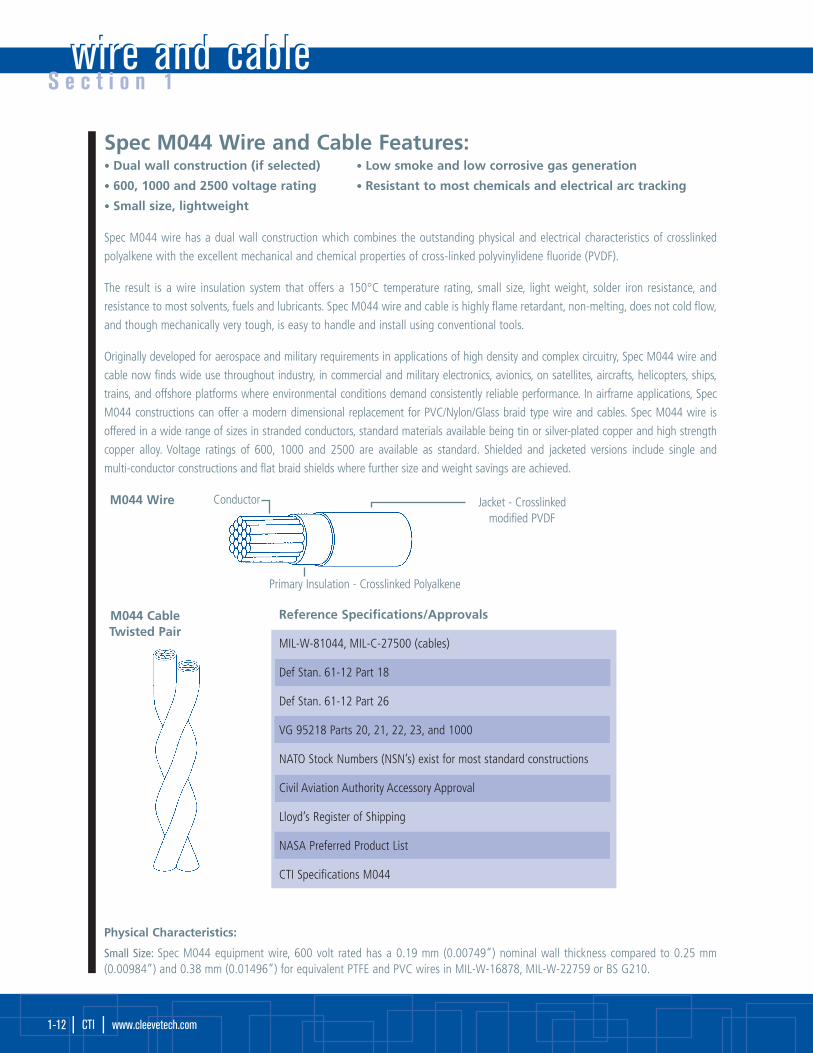
Spec M044 Wire and Cable Features:• Dual wall construction (if selected) • Low smoke and low corrosive gas generation
• 600, 1000 and 2500 voltage rating • Resistant to most chemicals and electrical arc tracking
• Small size, lightweight
Spec M044 wire has a dual wall construction which combines the outstanding physical and electrical characteristics of crosslinked
polyalkene with the excellent mechanical and chemical properties of cross-linked polyvinylidene fluoride (PVDF).
The result is a wire insulation system that offers a 150°C temperature rating, small size, light weight, solder iron resistance, and
resistance to most solvents, fuels and lubricants. Spec M044 wire and cable is highly flame retardant, non-melting, does not cold flow,
and though mechanically very tough, is easy to handle and install using conventional tools.
Originally developed for aerospace and military requirements in applications of high density and complex circuitry, Spec M044 wire and
cable now finds wide use throughout industry, in commercial and military electronics, avionics, on satellites, aircrafts, helicopters, ships,
trains, and offshore platforms where environmental conditions demand consistently reliable performance. In airframe applications, Spec
M044 constructions can offer a modern dimensional replacement for PVC/Nylon/Glass braid type wire and cables. Spec M044 wire is
offered in a wide range of sizes in stranded conductors, standard materials available being tin or silver-plated copper and high strength
copper alloy. Voltage ratings of 600, 1000 and 2500 are available as standard. Shielded and jacketed versions include single and
multi-conductor constructions and flat braid shields where further size and weight savings are achieved.
Reference Specifications/Approvals
MIL-W-81044, MIL-C-27500 (cables)
Def Stan. 61-12 Part 18
Def Stan. 61-12 Part 26
VG 95218 Parts 20, 21, 22, 23, and 1000
NATO Stock Numbers (NSN’s) exist for most standard constructions
Civil Aviation Authority Accessory Approval
Lloyd’s Register of Shipping
NASA Preferred Product List
CTI Specifications M044
Physical Characteristics:
Small Size: Spec M044 equipment wire, 600 volt rated has a 0.19 mm (0.00749”) nominal wall thickness compared to 0.25 mm(0.00984”) and 0.38 mm (0.01496”) for equivalent PTFE and PVC wires in MIL-W-16878, MIL-W-22759 or BS G210.
Primary Insulation - Crosslinked Polyalkene
ConductorM044 Wire Jacket - Crosslinkedmodified PVDF
M044 CableTwisted Pair

S e c t i o n 1
1-13wire and cable | CTI |
Light weight: Because of the thin wall and low density of the insulation materials considerable weight savings are made over similarly rated PTFE wires. eg: M044AO111-22 AWG equipment wire, 4.62 grams/metre max
22AWG PTFE equipment wire, MIL-W-22759 5.54 grams/metre max
General handling: The flexibility of Spec M044 and the ease with which it takes a 'set' makes it one of the easiest of the ‘high performance' wires to install. Stripping is done with conventional die blade strippers.
For details of appropriate tools see separate wire handling guide. The tin-plated conductor usually specified is easily soldered or crimped.The insulation may be hot stamp marked or printed and does not need etching before potting.
Lengths: Spec M044 is available in long continuous lengths and can be supplied for use on automatic cut and strip wire preparationmachines.
Typical Properties:
Temperature rating -65°C to +150°C
Voltage rating (thin wall) 600 V
Voltage rating (thick wall) 2500 V
Tensile strength and elongation of insulation 30 N/mm2, 230%
Notch propagation, 0.05 mm notch Pass
Solder iron resistance (370°C, 1 minute) Pass
Shrinkage 200°C
Low temperature bend -65°C
Voltage withstand (thin wall) 600 V
Insulation resistance (20°C) 1500 Megaohms for 1 km
Resistance: fuels, oils, solvents Pass
Environmental Performance:
Temperature rating: Spec M044 wire and cable is rated for continuous operation from -65°C to +150°C and for short periods at temperatures as high as 300°C. Heat ageing tests are routinely performed at temperatures of 200°C (168 h) and 300°C (6 h). In addition, Spec M044 insulation will not shrink back under repeated cycling.
Mechanical performance: Spec M044 wire provides better cut through resistance than some wires with much thicker walls.600 volt equipment wire M044AO111 (0.19 mm wall) has 40% greater cut through resistance than 600 volt PTFE insulated wire (0.25 mm wall).
Solder iron/overload resistance: The crosslinking of the materials used in Spec M044 makes them non-melting at high temperature. Asa result, Spec M044 wire is resistant to prolonged contact with solder irons and is resistant to current overloads which would melt mostthermoplastic insulation.
Chemical resistance: The dual wall construction of Spec M044 wire is highly resistant to many acids, alkalis, hydrocarbon solvents, fuels,lubricants, water and many missile fuels and oxidizers.
Cold flow: Crosslinking of Spec M044 prevents cold flow of the insulation, a recognized problem of some uncrosslinked materials.
wire and cablewire and cableS e c t i o n 1
1-14 | CTI | www.cleevetech.com
Voltage Ratings Outgassing: Standard available voltage ratings for Spec M044 wire are 600 volts (0.19 mm or 0.00749” wall thickness), 1000 volts (0.28 mm or 0.01102” wall) and 2500 volts (0.48 mm or 0.01890” wall).
Electrical Arc Track Resistance: Spec M044 insulation demonstrates a total resistance to arc tracking under both wet and dry conditions at aircraft system voltages.
Low Outgassing: For use in space applications, special constructions of Spec M044 wire are available with low outgassing characteristics, for use in an environment of high vacuum and high temperature.
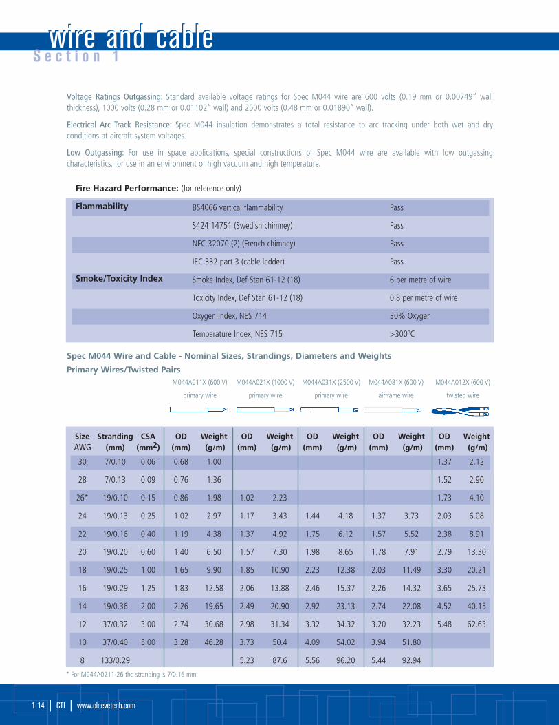
Fire Hazard Performance: (for reference only)
Flammability
Smoke/Toxicity Index
BS4066 vertical flammability Pass
S424 14751 (Swedish chimney) Pass
NFC 32070 (2) (French chimney) Pass
IEC 332 part 3 (cable ladder) Pass
Smoke Index, Def Stan 61-12 (18) 6 per metre of wire
Toxicity Index, Def Stan 61-12 (18) 0.8 per metre of wire
Oxygen Index, NES 714 30% Oxygen
Temperature Index, NES 715 >300ºC
Spec M044 Wire and Cable - Nominal Sizes, Strandings, Diameters and Weights
Primary Wires/Twisted PairsM044A011X (600 V) M044A021X (1000 V) M044A031X (2500 V) M044A081X (600 V) M044A012X (600 V)
primary wire primary wire primary wire airframe wire twisted wire
Size Stranding CSA OD Weight OD Weight OD Weight OD Weight OD WeightAWG (mm) (mm2) (mm) (g/m) (mm) (g/m) (mm) (g/m) (mm) (g/m) (mm) (g/m)
30 7/0.10 0.06 0.68 1.00 1.37 2.12
28 7/0.13 0.09 0.76 1.36 1.52 2.90
26* 19/0.10 0.15 0.86 1.98 1.02 2.23 1.73 4.10
24 19/0.13 0.25 1.02 2.97 1.17 3.43 1.44 4.18 1.37 3.73 2.03 6.08
22 19/0.16 0.40 1.19 4.38 1.37 4.92 1.75 6.12 1.57 5.52 2.38 8.91
20 19/0.20 0.60 1.40 6.50 1.57 7.30 1.98 8.65 1.78 7.91 2.79 13.30
18 19/0.25 1.00 1.65 9.90 1.85 10.90 2.23 12.38 2.03 11.49 3.30 20.21
16 19/0.29 1.25 1.83 12.58 2.06 13.88 2.46 15.37 2.26 14.32 3.65 25.73
14 19/0.36 2.00 2.26 19.65 2.49 20.90 2.92 23.13 2.74 22.08 4.52 40.15
12 37/0.32 3.00 2.74 30.68 2.98 31.34 3.32 34.32 3.20 32.23 5.48 62.63
10 37/0.40 5.00 3.28 46.28 3.73 50.4 4.09 54.02 3.94 51.80
8 133/0.29 5.23 87.6 5.56 96.20 5.44 92.94
* For M044A0211-26 the stranding is 7/0.16 mm

S e c t i o n 1
1-15wire and cable | CTI |
M044A111X (600V) M044A121X (6000 V) M044A181X (600 V) M044A112X (600 V)
1 conductor 1 conductor 1 conductor 2 conductors
Size Stranding OD Weight OD Weight OD Weight OD WeightAWG (mm) (mm) (g/m) (mm) (g/m) (mm) (g/m) (mm) (g/m)
28 7/0.13 1.47 4.92 1.60 5.33 2.38 9.40
26 19/0.10 1.57 5.82 1.73 6.51 2.59 12.05
24 19/0.13 1.83 8.20 1.98 9.18 2.26 11.69 2.99 16.12
22 19/0.16 2.00 10.30 2.24 12.35 2.57 15.39 3.35 21.50
20 19/0.20 2.26 14.02 2.54 17.40 2.77 19.09 3.76 27.97
18 19/0.25 2.62 19.70 2.82 22.61 3.02 23.98 4.32 38.24
16 19/0.29 2.79 23.40 3.02 26.63 3.25 27.97 4.67 44.93
14 19/0.36 3.22 32.50 3.45 36.15 3.73 38.48 5.53 64.28
12 37/0.32 3.70 45.67 4.14 49.55 4.19 52.10 6.50 91.51
Larger sizes are also available in some constructions depending on conductor type and construction required.
Screened and Jacketed Cable

wire and cablewire and cableS e c t i o n 1
1-16 | CTI | www.cleevetech.com
M044 X X X X X- Size- X/X- X
Jacket colour (in accordance with MIL-STD-681, white preferred)
Primary wire insulation colour (in accordance with MIL-STD-681)O=Black 3=Orange 7=Violet 1=Brown 4=Yellow 8=Grey 2=Red 5=Green 9=White 2L=Pink 6=BlueAdditional number after base colour indicates stripe
Conductor size (AWG)
Conductor type1 - Tin-plated copper2 - Silver-plated copper 4 - Silver-plated high strength copper alloy (SPHSCA)
Number of conductors 1 to 9
Class of wire1 - 600 V equipment wire2 - 1000 V equipment wire3 - 2500 V equipment wire4 - Space wire 600 V8 - Airframe wire - medium weight
Constructions0 - Primary wire & unscreened, unjacketed cables1 - Round braid screened & jacketed cable†
2 - Flat braid screened & jacketed cable†
3 - Round braid, screened cable, no jacket†
4 - Jacketed cable, no screen5 - Spiral screened and jacket 7 - 9 Special constructions†Screen material same as conductor material except all flatscreens and screen for conductor types 4 and 6 shall be tin-plated copper (other combinations are available).
TypeA - AWG conductor M - Metric conductorAM - Special CD - Custom design B - Special/ - Space & specialsD - Defense standard 61-12 Part 26
Basic specification number
Ordering Information: Standard equipment wires (M044AO11 1 12 to 30 AWG) in most common AWG’s and colours are kept instock. In addition, many of the most commonly used single/pair and triple screened cables are also stock items, as are some airframeconstructions. Other constructions and custom designed wire and cable are available on request.
PartNumberingSystem

S e c t i o n 1
1-17wire and cable | CTI |
Spec M759 Wire and Cable Features:• Single or dual wall constructions • Small size, ultra light weight
• Exceptional chemical resistance
Spec M759 wire is insulated with a cross-linked ETFE polymer. It has a temperature rating of -65°C to 200°C continuous, and
combines the easy handling of a flexible wire with excellent scrape abrasion and cut-through characteristics.
The dual wall airframe construction of this type of wire is currently used in numerous aircraft programmes. It has a choice of two total
wall thicknesses, both have a contrasting core colour to act as a damage indicator. Chosen for its balance of properties, Spec M759 wire
has outstanding resistance to chemicals and solvents and is not susceptible to UV and moisture degradation. Single wall equipment wire
constructions are available with reduced wall thicknesses for use inside boxes where flexibility and solder-iron resistance make it a wire
which is very easy to install. Both single and dual wall insulated wires are available in twisted pairs, triples, etc., and as screened and
jacketed cables.
Specifications meet the performance requirement of MIL-W-22759/32-35 and /41 to /46 and MIL-DTL-C-27500 (cables) Defense Standard
61-12 Part 33,VG95218 Part 20, Type D; Part 21, Type A; Part 22, Type A; Part 23, Type A, Part 1001 and Part 1002,VDE 9426, 9427, 9428,
British Standard 3G233, Underwriters Laboratory Style 3467.
Spec M759 Insulation System
Physical characteristics:
Size and weight: Spec M759 wire provides one of the most comprehensive wiring product ranges for aerospace and military users, with
a wide choice of conductor sizes and insulation wall thickness. The dual wall airframe wire has an insulation wall thickness of either
0.2 mm (0.00787”) or 0.25 mm (0.00984”) for robustness in unprotected harnesses and has excellent wire to wire abrasion proper-
ties. The single wall equipment wire has a 0.15 mm (0.00591”) wall thickness for use inside equipment and protected harnesses.
Handling: The excellent flexibility and low resilience makes Spec M759 the ideal wire to install, both in new aircraft and equipment and
for maintenance purposes. The wire is easily stripped with conventional tooling. The insulation is readily marked by hot stamp, ink jet or
laser, and can be potted without pre-etching (for full descriptions of the appropriate tools see wire handling guide).
Environmental Performance:Temperature rating: Spec M759 wire and cable is rated for continuous operation from -65°C to +200°C and for short periods at tem-
peratures as high as 400°C.
Mechanical performance: Crosslinking of the Spec M759 insulation significantly improves the following mechanical characteristics;
scrape (sharp edges), cross wire abrasion, cut-through resistance and creep resistance.
Solder iron/overload resistance crosslinking ensures that the insulation does not melt at a high temperature. As a result, Spec M759 wire
is resistant to hot solder irons and current overloads which would melt most thermoplastic insulation.
Chemical Resistance: Spec M759 is unaffected by all commonly used chemicals, eg. fuels, hydraulic fluids, defluxing agents,
cleaners, coolants and de-icers. It also shows excellent resistance to weathering (UV, ozone, pollutants, water).
Space Wire: Spec M759 is available in special versions suitable for use in outer space meeting both ESA and NASA requirements
for outgassing.
InsulationCrosslinked ETFEOver Conductor
Conductor

Spec M759Standard constructions, nominal sizes, strandings, diameters and weights
• Conductor • Primary Wire
• Twisted Pair • Screened & Jacket
M759-AWG conductor: Equipment/interconnect wires & cables
wire and cablewire and cableS e c t i o n 1
1-18 | CTI | www.cleevetech.com
Typical Properties:
Temperature rating (tin plated conductor)
Temperature rating (silver or nickel plated conductor)
Thermal endurance
Scrape abrasion (BS 3G233)
Flexing endurance (Boeing BSS 7324)
Voltage rating
Tensile strength + core elongation tensile strength + total elongationNotch propagation BS 3G230 0.05 mm notch
Solder iron resistance (370°C, 1 minute)
Solderability - Tin plated copper conductor BS 3G233 conditions
Shrinkage:
Long term water resistance
Permittivity 1 KHz (ASTM D150)
Dissipation factor (ASTM D150)
-65°C to +150°C
-65°C to +200°C
200°C, 10000 h
> 100 cycles at 150°C
> 1000 cycles
600 V
(Airframe wire only) 35 N/mm2, 125% (All primary wire) 35 N/mm2, 75% Pass
Pass
<0.8 seconds to wet
Will not hydrolyze
2.7
0.001
Size Stranding M759AO11X Weight M759A012X Weight M759A111X Weight M759A112X WeightAWG (mm) OD (g/m) OD (g/m) OD (g/m) OD (g/m)
(mm) (mm) (mm) (mm)
30 7/0.102 0.61 0.98 1.27 1.94 1.51 5.10 2.12 7.74
28 7/127 0.68 1.35 1.42 2.68 1.59 5.80 2.27 8.90
26 19/102 0.81 2.10 1.67 4.20 1.71 6.85 2.53 11.32
24 19/127 0.94 2.98 1.93 5.96 1.84 8.20 2.80 13.86
22 19/0.16 1.09 4.20 2.23 8.60 1.99 10.30 3.07 17.90
20 19/0.203 1.27 6.40 2.66 13.26 2.20 13.40 3.50 23.80
18 19/0.25 1.52 9.70 3.20 19.57 2.45 17.88 4.10 32.60
16 19/287 1.73 12.40 3.58 25.80 2.67 21.75 4.43 39.70
14 19/0.36 2.20 19.40 4.47 39.60 3.10 30.40 5.30 57.00
12 37/0.32 2.62 29.35 5.38 60.00 3.55 42.46 6.30 81.20
10 37/0.403 3.25 47.40 6.65 96.70 4.20 62.70
8 133/0.287 4.77 87.60 9.80 178.8 5.80 110.50
Single
Pair

S e c t i o n 1
1-19wire and cable | CTI |
Size Stranding M759AO81X Weight M759A082X Weight M759A111X Weight M759A112X WeightAWG (mm) OD (g/m) OD (g/m) OD (g/m) OD (g/m)
(mm) (mm) (mm) (mm)
26 19/102 1.01 2.50 2.10 5.10 1.71 6.85 2.63 11.32
24 19/127 1.14 3.40 2.33 6.84 1.84 8.20 2.80 13.86
22 19/0.16 1.27 4.80 2.64 9.98 1.99 10.30 3.07 17.90
20 19/0.203 1.47 7.00 3.07 14.75 2.20 13.40 3.50 23.80
18 19/0.25 1.78 10.70 3.63 21.90 2.45 17.88 4.10 32.60
16 19/287 1.95 13.40 4.06 27.50 2.67 21.75 4.43 39.70
14 37/0.36 2.40 20.50 4.90 42.30 3.10 30.40 6.30 57.00
12 37/0.32 2.82 30.50 5.80 63.00 3.55 42.46 6.30 81.20
10 37/0.403 3.40 48.30 7.10 99.10 4.20 62.70
M759-AWG conductor: Airframe wires & cables
CTI Wire and Cable ApplicationsCTI wire and cable products are used extensively in harsh environments such as in military vehicles, ships, aircrafts and applications
that demand the highest performance while exposed to corrosive fluids, high temperatures and physical abuse.
CTI wire and cable products optimize size and weight while still delivering the highest performance and electrical characteristics.

wire and cablewire and cableS e c t i o n 1
1-20 | CTI | www.cleevetech.com
M759 X X X X X- Size- X/X- X
Jacket colour (in accordance with MIL-STD-681, white preferred)
Primary wire insulation colour (in accordance with MIL-STD-681)O=Black 3=Orange 7=Violet 1=Brown 4=Yellow 8=Grey 2=Red 5=Green 9=White 2L=Pink 6=BlueAdditional number after base colour indicates stripe
Conductor size (AWG)
Conductor type1 - Tin-plated copper2 - Silver-plated copper 3 - Nickel-plated copper 4 - Silver-plated high strength copper alloy 6 - Nickel-plated high strength copper alloy
Number of conductors 1 to 9
Class of wire1 - 600 V equipment wire, light weight 2 - 600 V airframe wire, light weight 4 - 450 V equipment wire 8 - 600 V airframe wire, normal weight
Constructions0 - Primary wire & unscreened, unjacketed cable
1 - Round braid screened & jacketed cable†
2 - Flat braid screened & jacketed cable†
3 - Round braid, screened cable, no jacket†
4 - Jacketed cable, no shield
5 - Spiral-screened and jacketed cable†
8 - Special constructions (part numbers not coded)
9 - Special constructions including lightweight†Screen material same as conductor material except all flatscreens and screen for conductor types 4 and 6 shall be tin-plated copper (other combinations are special, refer to wireand cable division).
TypeA - AWG conductor M - Metric conductor/ - Space wire
Basic specification number
Typical ordering example:3 conductors, red, yellow, blue, 600 volt equipment wire with overall round braid, 20 AWG tinned conductor and white jacket:
total Part Number is M759A1 131-20-2/4/6-9
PartNumberingSystem
S e c t i o n 1
1-21wire and cable | CTI |
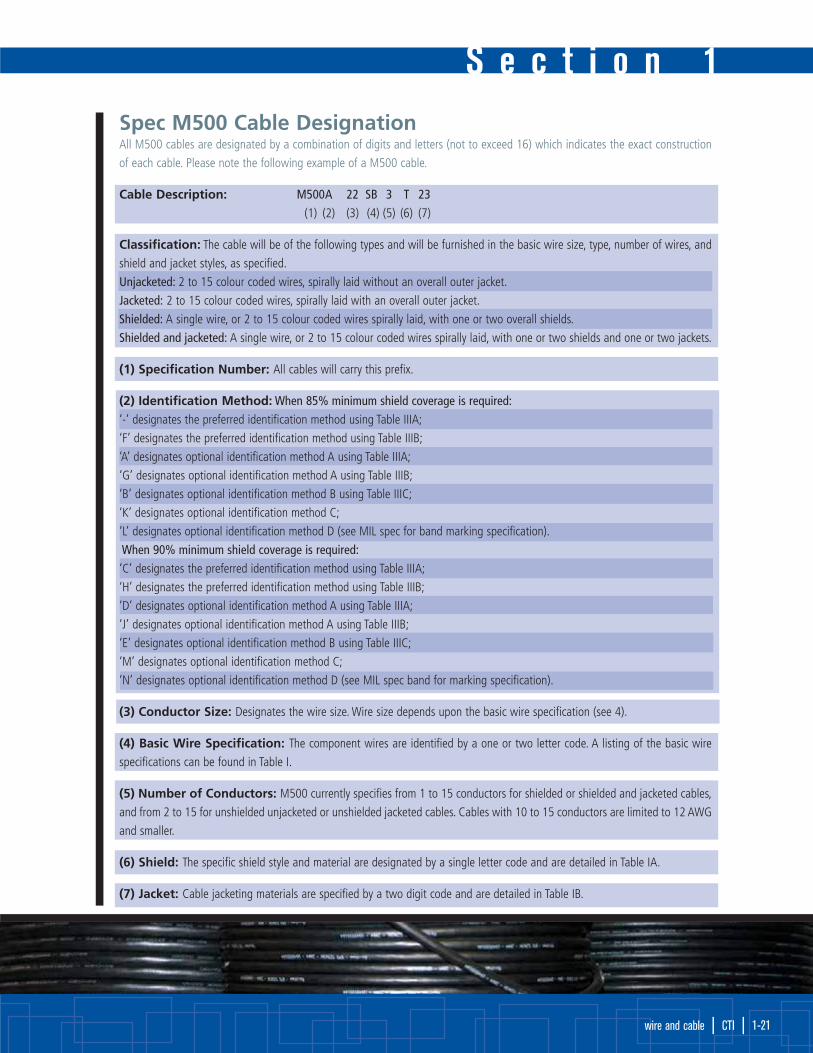
Spec M500 Cable DesignationAll M500 cables are designated by a combination of digits and letters (not to exceed 16) which indicates the exact construction
of each cable. Please note the following example of a M500 cable.
Cable Description: M500A 22 SB 3 T 23
(1) (2) (3) (4) (5) (6) (7)
Classification: The cable will be of the following types and will be furnished in the basic wire size, type, number of wires, and
shield and jacket styles, as specified.
Unjacketed: 2 to 15 colour coded wires, spirally laid without an overall outer jacket.
Jacketed: 2 to 15 colour coded wires, spirally laid with an overall outer jacket.
Shielded: A single wire, or 2 to 15 colour coded wires spirally laid, with one or two overall shields.
Shielded and jacketed: A single wire, or 2 to 15 colour coded wires spirally laid, with one or two shields and one or two jackets.
(1) Specification Number: All cables will carry this prefix.
(2) Identification Method: When 85% minimum shield coverage is required:
‘-’ designates the preferred identification method using Table IIIA;
‘F’ designates the preferred identification method using Table IIIB;
‘A’ designates optional identification method A using Table IIIA;
‘G’ designates optional identification method A using Table IIIB;
‘B’ designates optional identification method B using Table IIIC;
‘K’ designates optional identification method C;
‘L’ designates optional identification method D (see MIL spec for band marking specification).
When 90% minimum shield coverage is required:
‘C’ designates the preferred identification method using Table IIIA;
‘H’ designates the preferred identification method using Table IIIB;
‘D’ designates optional identification method A using Table IIIA;
‘J’ designates optional identification method A using Table IIIB;
‘E’ designates optional identification method B using Table IIIC;
‘M’ designates optional identification method C;
‘N’ designates optional identification method D (see MIL spec band for marking specification).
(3) Conductor Size: Designates the wire size. Wire size depends upon the basic wire specification (see 4).
(4) Basic Wire Specification: The component wires are identified by a one or two letter code. A listing of the basic wire
specifications can be found in Table I.
(5) Number of Conductors: M500 currently specifies from 1 to 15 conductors for shielded or shielded and jacketed cables,
and from 2 to 15 for unshielded unjacketed or unshielded jacketed cables. Cables with 10 to 15 conductors are limited to 12 AWG
and smaller.
(6) Shield: The specific shield style and material are designated by a single letter code and are detailed in Table IA.
(7) Jacket: Cable jacketing materials are specified by a two digit code and are detailed in Table IB.

Table I - Basic Wire Specifications
wire and cablewire and cableS e c t i o n 1
1-22 | CTI | www.cleevetech.com
A MIL-W-5086/11 CA MIL-W-22759/13 SP MIL-W-22759/43 MF MIL-W-81044/7
B MIL-W-5086/21, 2 CB MIL-W-22759/14 SR MIL-W-22759/44 MG MIL-W-81044/83
C MIL-W-5086/31, 2 CC MIL-W-22759/15 SS MIL-W-22759/45 MH MIL-W-81044/9
P MIL-W-5086/41 TE MIL-W-22759/16 ST MIL-W-22759/46 MJ MIL-W-81044/10
AA MIL-W-5086/51 TF MIL-W-22759/17 WB MIL-W-22759/803 MK MIL-W-81044/113
AB MIL-W-5086/61 TG MIL-W-22759/18 WC MIL-W-22759/813 ML MIL-W-81044/12
AD MIL-W-5086/71 TH MIL-W-22759/19 WE MIL-W-22759/823 MM MIL-W-81044/13
H MIL-W-8777, MS25471 TK MIL-W-22759/20 WF MIL-W-22759/833 MR MIL-W-81381/73
F MIL-W-8777, MS 27110 TL MIL-W-22759/21 WG MIL-W-22759/843 MS MIL-W-81381/83
EA MIL-W-22759/1 TM MIL-W-22759/22 WH MIL-W-22759/853 MT MIL-W-81381/93
E MIL-W-22759/2 TN MIL-W-22759/23 WJ MIL-W-22759/863 MV MIL-W-81381/103
RA MIL-W-22759/3 JB MIL-W-22759/28 WK MIL-W-22759/873 MW MIL-W-81381/113
RB MIL-W-22759/4 JC MIL-W-22759/29 WL MIL-W-22759/883 MY MIL-W-81381/123
VA MIL-W-22759/5 JD MIL-W-22759/30 WM MIL-W-22759/893 NA MIL-W-81381/133
WA MIL-W-22759/6 JE MIL-W-22759/31 WN MIL-W-22759/903 NB MIL-W-81381/143
SA MIL-W-22759/7 SB MIL-W-22759/32 WP MIL-W-22759/913 NE MIL-W-81381/173
TA MIL-W-22759/8 SC MIL-W-22759/33 WR MIL-W-22759/923 NF MIL-W-81381/183
LE MIL-W-22759/9 SD MIL-W-22759/34 JA MIL-W-25038/1 NG MIL-W-81381/193
LH MIL-W-22759/10 SE MIL-W-22759/35 JF MIL-W-25038/3 NH MIL-W-81381/203
RC MIL-W-22759/11 SM MIL-W-22759/41 MD MIL-W-81044/52 NK MIL-W-81381/213
RE MIL-W-22759/12 SN MIL-W-22759/42 ME MIL-W-81044/6 NL MIL-W-81381/223
1Not for use in aerospace applications. 2Inactive for new design. 3Not for Naval Air Systems Command usage.
Table IA - Shield MaterialLetter Code Maximum temperature
Single Double Description limit for shield materialShield Shield °C °F
U --- No shield N/A N/A
T V Round, tin-coated copper 150 302
S W Round, silver-coated copper 200 392
N Y Round, nickel-coated copper 260 500
F Z Round, stainless steel 400 752
C R Round, heavy nickel-coated copper 400 752
M K Round, silver-coated high strength copper alloy 200 392
P L Round, nickel-coated high strength copper alloy 260 500
G A Flat, silver-coated copper 200 392
H B Flat, silver-coated high strength copper alloy 200 392
* # Flat, nickel-coated copper 260 500
J D Flat, tin-coated copper 150 302
E X Flat, nickel-coated high strength copper alloy 260 500
I Q Flat, nickel-chromium alloy 400 752

S e c t i o n 1
1-23wire and cable | CTI |
Table IB - Jacket Material and ColourNumeric Code Temperature limit
Single Double Description for jacket materialJacket Jacket °C °F
00 00 No jacket N/A N/A
01 511 Extruded white polyvinylchloride (PVC) 90 194
022 522 Extruded clear polyamide in accordance with ASTM-D-4066 105 221
03 53 White polyamide braid impregnated with clear polyamide finisher over a polyester tape 105 221
04 54 Polyester braid impregnated with high temperature finishers over polyester tape 150 302
05 55 Extruded clear fluorinated ethylene propylene (FEP) 200 392
06 56 Extruded or taped and heat sealed white polytetrafluoroethylene (PTFE) 260 500
07 57 White polytetrafluoroethylene (PTFE) treated glass braid impregnated and coated 260 500
with polytetrafluoroethylene finisher over presintered polytetrafluoroethylene tape
083 583 Cross-linked white extruded polyvinylidene fluoride (PVDF) 150 302
09 59 Extruded white fluorinated ethylene propylene (FEP) 200 392
103 603 Extruded clear polyvinylidene fluoride (PVDF) 125 257
114 614 Tape of natural polyimide combined with clear fluorinated ethylene 200 392
propylene (FEP) wrapped and heat sealed with (FEP) outer surface
124 624 Tape of natural polyimide combined with fluorinated 200 392
ethylene propylene (FEP) wrapped and heat sealed with polyimide outer surface
14 64 Extruded white ethylene-tetrafluoroethylene copolymer (ETFE) 150 302
15 65 Extruded clear ethylene-tetrafluoroethylene copolymer (ETFE) 150 302
16 66 Braid of aromatic polyamide with high temperature finisher over presintered 200 392
polytetrafluoroethylene (PTFE) tape
175 675 Extruded white ethylene chlorotrifluoroethylene (ECTFE) 150 302
185 685 Extruded clear ethylene chlorotrifluoroethylene (ECTFE) 150 302
20 70 Extruded white perfluoroalkoxy (PFA) 260 500
21 71 Extruded clear perfluoroalkoxy (PFA) 260 500
22 72 Tape of polyimide combined with clear fluorinated ethylene propylene (FEP) wrapped 200 392
and heat sealed with opaque polyimide outer surface
23 73 Extruded white cross-linked modified ethylene-tetrafluoroethylene copolymer (XLETFE) 200 392
24 74 Tape layer of white polytetrafluoroethylene (PTFE) wrapped over 200 392
a tape layer of natural polyimide combined with FEP and heat sealed
1 Polyvinylchloride (PVC) materials shall not beused for aerospace applications
2 Jacket material 02/52 is not to be used forcables having a diameter of 0.251 in (6.38mm) or greater
3 Jacket materials 08, 10, 58, and 60 are not tobe used for cables having a diameter of 0.401in (10.19 mm) or greater.
4 Not for Naval Air Systems Command usage5 Inactive for new design.

wire and cablewire and cableS e c t i o n 1
1-24 | CTI | www.cleevetech.com
See Table I A and Table I B for jacket material cross-reference.1T = Tin, S = Silver, N = Nickel, F = Stainless steel, C = Heavy coated nickel
126 AWG is inactive for new design.2For MIL-W-81381 basic wire, the insulation colour may be dark yellow or unpigmented polyimide resin colour.
Table II - Allowable Shield and Jacket Materials for Each Basic Type Wire
Table IIIC - Colour of Insulation for Identification of WireSizes in accordance with MIL-STD-686
MIL-W-5086
MIL-W-8777
MIL-W-22759
slash sheets
1-12,20-23, 28-31
MIL-W-22759
slash sheets
13-19
MIL-W-22759
slash sheets
32-35, 41-46
MIL-W-22759
slash sheets
80-92
MIL-W-25038/1 &
/3
MIL-W-81044
MIL-W-81381
Wire Size 261 24 22 20 18 16 14 12 10 8 6 4 2 1 1/0 2/0
Insulation
Colour Black Blue Green Red White 2 Blue Green Yellow Brown Red Blue Yellow Red White Blue Green
Solid
T
S
T, S, N
T, S, N
T, S, N
T, S, N
F, C
T ,S ,S
T, S, N
00
00
00
00
00
00
00
00
00
Unshielded
Unshielded
Unshielded
Unshielded
Unshielded
Unshielded
Unshielded
Unshielded
Unshielded
01, 02, 03, 10
04
04, 05, 06, 07, 09,
14-18, 20, 21
04, 05, 09, 14-18,
20,21
04, 05, 08, 09,
14-18, 20, 21,
23, 24
04, 05, 06, 07, 09,
11, 12,14-18, 20,
21, 22, 24
06,07
04, 08, 09,14,
16, 23
05, 09, 11, 12, 22
T
S
T, S, N
T, S, N
T, S, N
T, S, N
F, C
T ,S ,S
T, S, N
01, 02, 03, 10
04
04, 05, 06, 07, 09,
14-18, 20, 21
04, 05, 09, 14-18,
20,21
04, 05, 08, 09,
14-18, 20, 21,
23, 24
04, 05, 06, 07, 09,
11, 12,14-18, 20,
21, 22, 24
06,07
08, 09, 14,
16, 23
05, 09, 11, 12, 22
Cable TypeShielded Jacketed Shielded and Jacketed
Basic Wire Shield Jacket Shield Jacket Shield JacketSpecifications Material1 Material Material Material Material1 Material

S e c t i o n 1
1-25wire and cable | CTI |
Table IIIA - Circuit Identification Colours for Basic Wires in Cablein accordance with MIL-W-22759, MIL-W-25038, MIL-W-81044, or MIL-W-81381
1 Except where preferred colour on basic wire specification sheet is not white.2 Where basic wire is MIL-W-81381, a brown helical stripe shall be used.3 Where basic wire is MIL-W-81381, a brown and white helical stripes shall be used.4 For cables having more than 10 conductors, the wires shall be a white base identified by double colour tracers as indicated.5 Inactive for new design
Table IIIB - Circuit Identification Colours for Basic Wires in Cablein accordance with MIL-W-5086', MIL-W-8777, MIL-W-22759, MIL-W-25038, MIL-W-81044, or MIL-W-81381
1 Inactive for new design MIL-W-5086.2 Colour designation indicated a solid colour with stripe, e.g., red/white - solid red insulation with a white stripe.
No. ofWires Wire Number
inCable 1 2 3 4 5 6 7 8 9 10 11 12 13 14 15
1 Basic
(white)
2 White Blue
3 White Blue Orange
4 White Blue Orange Green
5 White Blue Orange Green Red
6 White Blue Orange Green Red Black
7 White Blue Orange Green Red Black Yellow2
8 White Blue Orange Green Red Black Yellow2 Violet
9 White Blue Orange Green Red Black Yellow2 Violet Gray
10 White Blue Orange Green Red Black Yellow2 Violet Gray Brown3
114 White Blue Orange Green Red Black Yellow2 Violet Gray Brown3 Blue/Blue
124 White Blue Orange Green Red Black Yellow2 Violet Gray Brown3 Blue/Blue Orange/Orange
134 White Blue Orange Green Red Black Yellow2 Violet Gray Brown3 Blue/Blue Orange/Orange Green/Green
144 White Blue Orange Green Red Black Yellow2 Violet Gray Brown3 Blue/Blue Orange/Orange Green/Green Red/Red
154 White Blue Orange Green Red Black Yellow2 Violet Gray Brown3 Blue/Blue Orange/Orange Green/Green Red/Red Black/Black
No. ofWires Identification Colours for Respective Wires in Cable
inCable 1 2 3 4 5 6 7 8 9 10 11 12 13 14 15
1 Basic
(white)
2 Red, blue
3 Red, blue, yellow
4 Red, blue, yellow, green
5 Red, blue, yellow, green, basic
6 Red, blue, yellow, green, basic, black
7 Red, blue, yellow, green, basic, black, brown
8 Red, blue, yellow, green, basic, black, brown, orange
9 Red, blue, yellow, green, basic, black, brown, orange, violet
10 Red, blue, yellow, green, basic, black, brown, orange, violet, gray
11 Red, blue, yellow, green, basic, black, brown, orange, violet, gray, red/white2
12 Red, blue, yellow, green, basic, black, brown, orange, violet, gray, red/white2, blue/white2
13 Red, blue, yellow, green, basic, black, brown, orange, violet, gray, red/white2, blue/white2, yellow/white2
14 Red, blue, yellow, green, basic, black, brown, orange, violet, gray, red/white2, blue/white2, yellow/white2, green/white2
15 Red, blue, yellow, green, basic, black, brown, orange, violet, gray, red/white2, blue/white2, yellow/white2, green/white2, black/white2

FRCL Multi-Conductor Cable
CTI has been recognized as a leading manufacturer of electrical and electronic wire and cable. We offer a broad
and complete line of instrumentation, thermocouple, communications, control, and other types of wire and cable.
Our specialty is in ‘custom cable constructions’.
CTI can manufacture and/or supply a broad spectrum of special cables for OEM equipment or replacement
applications. We can work from your specifications or design custom cables according to your needs.
Cables are available with or without shielding; shields can be conventional braids, spiral braids, aluminum foil
or conductive plastics. Taped, served and wrapped shields are also available. Cable jacketing options include
extruded cross-linked compounds as well as vinyl, nylons, polyethylenes, polyurethanes and fluorocarbons,
elastomers and vitons.
For further information about special cables, please contact CTI. We want to work with you to develop the right
features and functions for your application, within a unique custom package.
Short runs are another specialty, with minimum order quantities as low as any in the industry.
By definition, off-the-shelf cable products do not give end-users the chance to decide on many critical features of
the finished product. Large cable companies have already decided upon the design, materials, tolerances, and
manufacturing techniques to be used for their products before the customer has an opportunity to define
their needs.
CTI’s custom cable products are designed and manufactured to suit the specific needs of our customers' appli-
cations. They are an integral part of the system and its performance.
Advantages of a custom-engineered cable:• Determine physical and electrical tolerances;
• Define the components (insulation, shield, jacket, etc.) that best fit your application;
• Combine various functions, such as power, signal, coaxial, shielded sub-assemblies, and optical fiber
into one cable;
• Optimize the conductor count, stranding, size, and colour-code.
Our extensive engineering and manufacturing capabilities allow us to be able to meet the needs of virtually any
electrical wire and cable application. Our products can be found everywhere from the wiring in electrical devices,
aircraft, ships and military vehicles, through to automotive and industrial applications.
wire and cablewire and cableS e c t i o n 1
1-26 | CTI | www.cleevetech.com

Standards and specifications for cable insulation have
been developed by ASTM, ICEA, CSA, UL, NEC and
others. We advise consulting these organizations for
complete, current, and accurate data.
Local code requirements often exist regulating wire and
cable specification and installation. Always check code
requirements before specifying or installing your wire
and cable.
Jacketing insulation
Jackets: Includes many of the primary insulating
materials, containing nylon, neoprene, hypalon,
ethylene propylene rubber, polyurethane, elastomers,
vitons or zero halogen etc. Jackets cover and protect the
enclosed wires or core against damage, chemical attack,
fire and other harmful elements which may be present in
the operating environment.
Our conductor offering includes (all can be specified in solid or stranded constructions):• Bare copper • Tinned copper • Plated copper • All major thermocouple alloys
We offer numerous insulating and jacketing materials:• Polyethylene • Elastomers • Polypropylene • Vitons®
• Polyurethane • Zero Halogen • Nylons • Teflon (TFE, FEP, PFA, Tefzel)
• TPE • All heat shrinkable tubing options
Our shielding capabilities include a variety of foil shields and metal braids. We can cross reference competitor part numbers and
manufacture cables of equal or higher quality with greater flexibility in design.
The most important part of any cable is the insulation of the conductors. When choosing materials to insulate conductors or cables,
many factors should be taken into consideration. These include electrical properties, mechanical properties, chemical properties, thermal
properties, and more.
S e c t i o n 1
1-27wire and cable | CTI |
Electric Properties:
- dielectric strength
- insulation resistance
- insulation power factors
- charging current
- arc resistance
- tracking susceptibility
Chemical Properties:
- moisture absorption
- resistance to oil, gas, acids and alkalis
- stability when exposed to sunlight, ozone, or flames
Mechanical Properties:
- toughness and flexibility
- tensile, elongation and crushing strengths
- resistance to abrasion or moisture
- brittleness
Thermal Properties:
- expansion and contraction
- softening and flow temperature
- compatibility with operating, ambient, or emergency overload
and short circuit conditions
Example:FRCL-602006B

Primary Wire For Commercial ApplicationsGeneral Purpose Primary Wire: Plastic primary single conductor wire, with durable thermoplastic PVC
compound that resists chemical attack, abrasion and heat to 90˚C (194˚F). Clean stripping for easy use. Type GPT
to SAE specification J1128.
SXL Heat Resistant Primary Wire: General purpose, low tension cable, crosslinked polyethylene insulated jackets providetoughness combined with outstanding heat, grease, oil, gasoline and chemical resistance. Clean stripping for easy use. Ideally suited for heavy-duty applications. 125˚C (257˚F) temp rating, 50 volt, chemical attack, abrasion and heat to 90˚C (194˚F). Type GPT to SAEspecification J1128.
TEW 600 Volt Rated Primary Wire: For use in internal wiring of electrical equipment. Applications include electric ranges, heat-
ing equipment, lighting fixtures, panels and meters. Stranded copper conductor, PVC insulation, 600 volts, -40˚C (-40˚F) to 105˚C (221˚F)
temp rating. Meets CSA and UL requirements.
Gauge Length Outside Stranding Part Numbers(ft) Diameter (in) (in) Black Blue Brown Green Orange Red White Yellow
Mini Spools
18 50 0.091 16 x 0.010 CTI68051 CTI68052 CTI68053 CTI68054 CTI68056 CTI65057 CTI68059
16 35 0.104 19 x 0.0113 CTI68061 CTI68062 CTI68063 CTI68064 CTI68065 CTI68066 CTI68067
14 25 0.119 19 x 0.0142 CTI68068 CTI68069 CTI68070 CTI68071 CTI68072 CTI68073 CTI68074
12 15 0.145 19 x 0.0179 CTI68075 CTI68076 CTI68983 CTI68922 CTI68077 CTI68078 CTI68928
10 10 0.175 19 x 0.0234 CTI68080 CTI68906 CTI68081 CTI68980 CTI68082 CTI68981 CTI68979
50’ (15.2m) Spool
10 50 0.175 19 x 0.0234 CTI68102 CTI68103 CTI68104 CTI68105 CTI68106 CTI68107 CTI68108
100’ (30.5m) Spool
18 100 0.091 16 x 0.010 CTI68000 CTI68001 CTI68002 CTI68003 CTI68005 CTI68006 CTI68007
16 100 0.104 19 x 0.0113 CTI68010 CTI68011 CTI68012 CTI68013 CTI68014 CTI68015 CTI68016 CTI68017
14 100 0.119 19 x 0.0142 CTI68020 CTI68021 CTI68022 CTI68023 CTI68024 CTI68025 CTI68026 CTI68027
12 100 0.145 19 x 0.0179 CTI68030 CTI68031 CTI68032 CTI68033 CTI68035 CTI68036 CTI68037
8 100 0.239 7 x 12 x 0.0142 CTI68050 CTI68155
6 100 0.285 7 x 7 x 0.0226 CTI68060 CTI68165
4 100 0.354 7 x 27 x 0.0142 CTI68175
1000’ (305m) Spool
18 1000 0.091 16 x 0.010 CTI68200 CTI68201 CTI68202 CTI68203 CTI68205 CTI68206 CTI68207
16 1000 0.104 19 x 0.0113 CTI68210 CTI68211 CTI68212 CTI68213 CTI68214 CTI68215 CTI68216 CTI68217
14 1000 0.119 19 x 0.0142 CTI68220 CTI68221 CTI68222 CTI68223 CTI68224 CTI68225 CTI68226 CTI68227
12 1000 0.145 19 x 0.0179 CTI68230 CTI68231 CTI68232 CTI68233 CTI68234 CTI68235 CTI68236 CTI68237
10 1000 0.175 19 x 0.0234 CTI68240 CTI68241 CTI68242 CTI68243 CTI68245 CTI68246 CTI68247
Gauge Outside Stranding Part NumbersDiameter (ft) (in) Black Blue Brown Green Orange Red White Yellow
100’ (30.5m) Spool
16 0.129 19 x 0.0113 CTI68840 CTI68841 CTI68842 CTI68843 CTI68847 CTI68844 CTI68845 CTI6884614 0.151 19 x 0.0142 CTI68850 CTI68851 CTI68852 CTI68853 CTI68857 CTI68854 CTI68855 CTI6885612 0.172 19 x 0.0179 CTI68860 CTI68861 CTI68862 CTI68863 CTI68867 CTI68864 CTI68865 CTI6886610 0.203 19 x 0.0234 CTI68770 CTI68773 CTI68774 CTI68775 CTI687768 0.226 7 x 12 x 0.0142 CTI68780 CTI68784 CTI68785
Gauge Outside Stranding Part NumbersDiameter (ft) (in) Black Blue Brown Green Orange Red White Yellow Grey
100’ (30.5m) Spool
16 0.122 26 x 0.010 CTI68609 CTI68610 CTI68611 CTI68612 CTI68613 CTI68614 CTI68615 CTI68616 CTI6861714 0.136 41 x 0.010 CTI68618 CTI68619 CTI68620 CTI68621 CTI68622 CTI68623 CTI68624 CTI68625 CTI6862612 0.159 65 x 0.010 CTI68627 CTI68628 CTI68629 CTI68630 CTI68631 CTI68632 CTI68633 CTI68634
wire and cablewire and cableS e c t i o n 1
1-28 | CTI | www.cleevetech.com

S e c t i o n 1
1-29wire and cable | CTI |
Cable For Commercial ApplicationsType GPT 2, 3 & 4 Conductor: General purpose, low-tension plastic, insulated cable withgrey PVC outer jacket. SAE specification J1128.
Type GPT 2 Conductor, Parallel Jacketed PVC Cable: General purpose low-tension, plastic
insulated cable with PVC compound
insulation. Bonded parallel red and brown
conductor SAE specification J1128.
Type GPT Parallel Jacketed, 3 & 4 Conductor PVC Cable: General purpose, low-tension, plastic
insulated cable with bonded parallel 3
and 4 conductor. SAE specification J1128.
Speaker Wire,Clear Two-Tone Vinyl Jacketed Cable:Bonded parallel conductors. Wire is polarized using
bare copper stranding on one side and tin plated copper
stranding on the other side.
Part # Conductors/ Stranding Red Green Black WhiteGauge (in)
100’ (30.5 m) SpoolCTI68430 2/16 19 x .0113 • •CTI68431 2/14 19 x .0142 • •CTI68432 2/12 19 x .0179 • •CTI68570 3/16 19 x .0113 • • •CTI68571 3/14 19 x .0142 • • •CTI68580 4/16 19 x .0113 • • • •CTI68581 4/14 19 x .0142 • • • •1000’ (305 m) SpoolCTI68435 2/16 19 x .0113 • •CTI68436 2/14 19 x .0142 • •CTI68437 2/12 19 x .0179 • •CTI68475 3/16 19 x .0113 • • •CTI68576 3/14 19 x .0142 • • •CTI68585 4/16 19 x .0113 • • • •CTI68586 4/14 19 x .0142 • • • •
Part # Conductors/ Stranding Green Brown Yellow WhiteGauge (in)
100’ (30.5 m) SpoolCTI68089 3/16 19 x .0113 • • •CTI68091 3/14 19 x .0142 • • •CTI68090 4/16 19 x .0113 • • • •CTI68092 4/14 19 x .0142 • • • •
250’ (76 m) SpoolCTI68481 4/16 19 x .0113 • • • •
1000’ (305 m) SpoolCTI68093 4/14 19 x .0142 • • • •
Part # Conductors/ Stranding LengthGauge (in) (ft)
CTI68401 2/16 19 x .0113 100 (30.5m) spoolCTI68405 2/16 19 x .0113 250 (76.2m) spoolCTI68416 2/16 19 x .0113 2500 (762m) spool
Part # Conductors/ Stranding LengthGauge (in) (ft)
CTI68500 2/22 19 x .0113 100 (30.5m) spool

connectors, contacts and protection capsconnectors, contacts and protection capsS e c t i o n 2
Selection Guide for CTI Connectors, Contacts and Connector Protection Caps. CTI carries an extensive inventory of military, industrial and commercial connectors. These products are managed
in our MRP system via the military or commercial part number as well as by a CTI spec number which allows us
to offer our customers the most competitive pricing and available stock, while only supplying the very highest
quality parts manufactured by some of the best electrical interconnect companies in the world.
Connectors can be ordered by the military part numbers and, certificates of compliance and test reports can be
provided. Connectors can also be ordered by the manufacturer’s part numbers with the same level of supporting
documentation available as required.
Alternatively, connectors can be ordered by the CTI part number, which allows us the option of suppling the best
suited product for each specific need. All parts supplied under the CTI part number are form fit and functionally
equivalent and will be based on the specific needs of the end user.
Some of the approved specifications and performance criteria as it relates to the military, aerospace and
industrial industries are as follows
CTI Connector part numbers. Cleeve has allocated a prefix to standard military part numbers in order to
differentiate between specific manufacturer’s products and also to allow for multiple supply options.
Examples: D38999/26-WC35PN would be replaced with FAE26-WC-35PN
and MS3475W14-4SN would be replaced with FAE-3475-W14-4SN
All variations such as plating, contact style arctic coupling rings etc. are available upon request and will be
allocated specific part numbers as required
MIL-C-26482 Series I and II Military specification, connectors
MIL-C-38999 Series I, II, III and IV Military specification, connectors
MIL-C-5015 Military specification, connectors
FAE347* series Circular connectors
D38999 (FAE 2* series) Circular connectors
MIL-C-28840 Circular connectors
SCC-3181 series Circular protection caps
SCC-8993 series Circular protection caps
SCC-4841 Circular protection caps
2-30 | CTI | www.cleevetech.com

Connector Part Number for FAE-347 series: FAE - 347 5 - Z 10 - 07 P N
Connector prefix
Connector type and
Class (specification number)
Shell style Insert rotation or clocking
Service class Contact configuration
Shell size Insert arrangement
Connector Part Number for FAE-20 through 27 series: FAE - 26 W Z 35 P N
Connector prefix
Shell style Insert rotation or clocking
Service class Contact configuration
Shell size (A through J) Insert arrangement
Connector Kits: Also available and in which CTI will
include all the parts required for a specific application.
FRCK ****
Project prefix
(if applicable)
Sequential number
Depicts kit contents (see kit list for details)
Kit Content Options:
• Contacts
• Backshells
• Protection caps
• Heat shrinkable molded parts
S e c t i o n 2
Product Number Description Performance Specifications
FAE-3475-XXX-XXXX Plug: aluminum alloy, specified finish over MIL-C-26482 Series IIelectroless nickel, arctic coupling ring option.
FAE-3474-XXX-XXXX Jam nut receptacle: aluminum alloy, MIL-C-26482 Series IIspecified finish over electroless nickel.
FAE-3470-XXX-XXXX Wall mount receptacle: aluminum alloy, MIL-C-26482 Series IIspecified finish over electroless nickel.
FAE-3472-XXX-XXXX Wide flange: wall mount receptacle, aluminum alloy, MIL-C-26482 Series IIspecified finish over electroless nickel.
FAE-26-XXXXXX Plug: aluminum or composite. Technical spec ref. MIL-C-38999
FAE-24-XXXXXX Jam nut receptacle: aluminum or composite. Technical spec ref. MIL-C-38999
FAE-20-XXXXXX Square flange receptacle: aluminum or composite Technical spec ref. MIL-C-38999
SCC-8993 Protection cap MIL-C-38999 Series III connectors
SCC-8992 Protection cap MIL-C-38999 Series II connectors
SCC-3181 Protection cap FAE-347X Series receptacle connectors
SCC-3180 Protection cap FAE-347X Series plug connectors
2-31wire and cable | CTI |

An Overview of Connectors
This section of the CTI catalogue is intended to be used as a ready reference to typical standard, miniature and subminiature cylindri-
cal connector part numbers and terminology. This section should guide you in becoming familiar with the product, in order to better
allow you to determine how your needs can be supported.
Cylindrical Connectors
Basic Components
1. Shell (houses inserts & contacts)
2. Insert (dielectric contact insulator) pin or socket
3. Contact (wire end termination) (electrical engagement)
4. Coupling nut
5. Accessories (wire seals, cable seals, wire support, etc.)
connectors, contacts and protection capsconnectors, contacts and protection capsS e c t i o n 2
Connector Terms and Definitions Solder Contact: A contact to which wire is joined by soldering
Crimp Contact: A contact to which wire is joined by mechanical ‘squeeze’
Plug: The cable/coupling half of a mating pair
Receptacle: The panel/receiving half of a mating pair
Mating Pair: Two connectors that couple together. Shell size insert arrangement and rotation must be compatible
Plating: The metal finish applied to contacts and or shell components (protective) to resist corrosion and wear
Grommet: Resilient part at back of insert (attached or separate); gives wire moisture seal
Gland: Resilient ring in rear accessory, provides seal on jacketed cable
Sealing Plug: Plastic type slug, placed in unused grommet holes to seal
Grounding Fingers: A metal strap around plug shell for positive shell-to-shell conductivity/shielding
Hermetic: A connector with a fused glass insert for air tightness
Mating/Unmating Forces: Torque required to couple/uncouple a mating pair of connectors or contacts
Rear Termination: An accessory which threads to back of shell (see section 3)
Strain Relief: A type of accessory which clamps wires for support (see section 3)
Potting Boot: A type of accessory which forms a mold for potting compound (see section 4)
EMI or RFI Backshell: A type of accessory to terminate wire shielding (see section 3)
Interface Seal: A resilient part on the face of pin inserts which provides moisture seal
Shell Sizes
Contact Size 22D 22M 22 20 16
Wire Size (AWG) 22-28 24-28 22-26 20-24 16-22
Contact Size
American Wire Gauge 12 8 4 0
Wire Size (AWG) 12-14 8-10 4-6 0-2
| CTI | www.cleevetech.com 2-32

S e c t i o n 2
Example:Wall Mount Receptacle
Example:Plug
Contact Size 6 8 10 12 14 16 18 20 22/22D
Wire Size (AWG) 6 8 10 12-14 14-16 16-20 18-20 20-24 22-26
Note: Contacts available to accommodate other wire sizes upon request. Extended length and PC tail contacts also available
connectors, contacts and protection caps | CTI | 2-33
Major MIL-Specifications by Type:• Miniature, MIL-C-26482
• Widely used small style and size of connectors. Extensive use on military equipment including aircraft as well as commercial applications.
• 3 point bayonet coupling available with either crimp or solder type contacts.

MIL-C-26482 Military Part Number can be replaced by CTI’s ‘FAE’ Series part number.
For example: MS 347 0 L 18 -32 P W can be replaced with FAE 3470L18-32PW
1. ‘MS’ or ‘FAE’ designates Military or commercial standard
2. Specification Number: ‘347’ designates basic family number for MIL-C-26482, Series 2 crimp type
3. Shell Style: ‘0’ designates narrow flange wall mounting receptacle;
‘1’ designates cable connecting receptacle;
‘2’ designates wide flange wall mounting receptacle;
‘4’ designates jam nut receptacle;
‘5’ designates plug with grounding fingers;
‘6’ designates straight plug.
4. Service Class: ‘A" designates grommet seal, 200°C, non-conductive anodic coating;
‘L' designate fluid resistant, 200°C, conductive electroless nickel finish;
‘W’ designates fluid resistant, 175°C, olive drab cadmium over nickel, conductive finish, 500/hr. salt spray;
‘Z designates a zinc cobalt finish.
Note: absence of a letter to designate will result in CTI ‘best available’ option being supplied.
5. Shell Size: ‘18’ designates shell size. Shell sizes 8 through 24 available.
6. Insert Arrangement: ‘18-32’ designates insert arrangement.
7. Contact Configuration: ‘P’ designates pin contacts ‘S’ designates socket contacts.
8. Insert Rotation: ‘W’, ‘X’, ‘Y’, 'T' designate that insert is rotated in its shell from ‘normal’ position. No letter required for normal (no
rotation) position.
connectors, contacts and protection capsconnectors, contacts and protection capsS e c t i o n 2
| CTI | www.cleevetech.com 2-34

MIL-C-38999 Military Part Number can be replaced by FAE 2* Series part number.
Widely used small style and size of connectors. Extensive use on military equipment including aircraft as
well as commercial applications. Available with crimp type contacts and threaded bayonet style coupling.
To more easily illustrate ordering procedure by military designation, part number D38999/20FA35PB is
shown as follows:
For example: CTI alternative part number FAE20-FA35PB, D38999/20-FA35PB designates MIL-C-38999 Series III Connector.
Shell Style: ‘20’ designates wall mount receptacle
‘21’ designates box mount receptacle, hermetic
‘23’ designates jam nut receptacle, hermetic
‘24’ designates jam nut receptacle
‘25’ designates solder mount receptacle, hermetic
‘26’ designates straight plug
‘27’ designates weld mount receptacle, hermetic
Service Class: ‘C’ non-conductive, anodic coated aluminum, 500 hour salt spray, 200°C (environmental resisting);
‘F’ electroless nickel plated aluminum, optimum EMI shielding effectiveness -65dB Ca 10GHz specification min.,
48 hour salt spray, 200°C (conductive, environmental resisting);
‘K’ corrosion resistant stainless steel, firewall capability, plus 500 hour salt spray resistance, EMI -45 dB Ca 10GHz
specification min., 200°C;
‘W’ corrosion resistant olive drab cadmium plate aluminum, 500 hour extended salt spray, EMI -50 dB Ca 10GHz
specification min., 175°C;
‘Y’ hermetic seal, passivated stainless steel, 200°C S (non-hermetic connectors), nickel plated stainless steel,
optimum EMI shielding effectiveness -65 dB Ca 10GHz specification min., 48 hour salt spray, 200°C;
‘N’ (hermetic connectors), nickel plated stainless steel, 200°C;
‘J’ olive drab cadmium plate (175°C) composite, environmental resisting, corrosion resistant;
‘M’ electroless nickel plate (200°C) composite, environmental resisting, corrosion resistant.
Shell Size: MIL-C-38999, sizes 9 - 25
A B C D E F G H J
9 11 13 15 17 19 21 23 25
Specifications • MIL-C-38999, Series III
- 100% scoop-proof;
- High density contact arrangements;
- Contact sizes 12 through 22D plus size 8, 12, 16 coaxial, and size 8 twinaxial removable crimp, PCB, wire wrap, coaxial, triaxial,
twinaxial and fiber optic contact styles available. Options include hermetics, filters and thermocouples;
- Self-locking, quick disconnect threaded coupling;
- Corrosion resistant: shells of stainless steel or cadmium plate over nickel withstand a 500 hour salt spray exposure;
- Moisture resistance: improved interfacial seal design prevents electrolytic erosion of contacts;
- EMI shielding: designed to obtain metal-to-metal coupling, the FAE connector provides a superior EMI shielding capability;
- Vibration/shock: operates under severe, high temperature shock and vibration testing through 200°C;
- Firewall capability: available in stainless steel shell, Class K;
- Locksmith keying: 5 keyway polarization provides 5 alternate rotations
S e c t i o n 2
connectors, contacts and protection caps | CTI | 2-35

connectors, contacts and protection capsconnectors, contacts and protection capsS e c t i o n 2
Contact RatingContact Test Current Maximum Millivolt Drop*
Size Crimp Hermetic Crimp** Hermetic**22D 5 3 73 8520 7.5 5 55 6016 13 10 49 8512 23 17 42 85
10 (Power) 33 N/A 33 N/A
*Maximum millivolt drop data is determined by measuring resistance of mated contacts from end to end** When using silver plated wire
Finishing DataService Class
Finish MilitaryAnodic coating (non-conductive) CElectroless nickel FOlive drab cadmium plate nickel base WStainless steel with nickel plate SStainless steel KOlive drab cadmium plate, composite JElectroless nickel plate, composite M
Hermetic ConnectorsMaterial/Finish MilitaryStainless steel YStainless steel, nickel plate N
Service Suggested Operating Voltage Test Voltage Test Voltage Test Voltage Test Voltage(Sea Level)
Rating AC (RMS) DC (Sea Level) 50,000 ft. 70,000 ft. 110,000 ft.M 400 550 1300 VRMS 550 VRMS 350 VRMS 200 VRMSN 300 450 1000 VRMS 400 VRMS 260 VRMS 200 VRMS1 600 850 1800 VRMS 600 VRMS 400 VRMS 200 VRMS
11 I 900 I 1250 I 2300 VRMS I 800 VRMS I 500 VRMS I 200 VRMSThe establishment of electrical safety factors is left entirely in the designer’s hands, since they are in the best position to know what peak voltages, switching surges, transients,
etc. can be expected in a particular circuit.
Service Rating
Crimp Well Data Hermetic Well DataContact Well Nominal Well Minimum
Size Diameter Well Depth Diameter Well Depth
22D 0.0345 ± 0.001 0.141 0.036 ± 0.004 0.094
20 0.047 ± 0.001 0.209 0.044 ± 0.004 0.125
16 0.067 ± 0.001 0.209 0.078 ± 0.004 0.141
12 0.100 ± 0.002 0.209 0.116 ± 0.004 0.141
10 (Power) 0.137 ± 0.002 0.355 N/A N/A- Shell grounding fingers are standard on all plugs triple-web grommet seal- DOD preferred
| CTI | www.cleevetech.com 2-36

S e c t i o n 2MIL-SPEC Cross Reference Data and General Information
Contact Contact Sizes in Coupling OtherMIL-Spec Description Termination and Series Method Notes
Removal Wire GaugeMIL-C-5015 Power type connectors, large contacts, Solder or crimp, 16 thru 0 Threaded 31OX solder,
older series had solder contacts; front or rear removal 340X crimp F. R.,newer has crimp 345X crimp R. R.,
GT series reverseBayonet coupling
MIL-C-26482 Miniature connector. Contacts are Solder or crimp, 20, 16, 12 Bayonet thread, 311X solder,medium size, both power and front or rear removal version 312X crimp F. R.
Series I crimp signal currents, solder or crimp non-military 347X crimp R. R.MIL-C-22992 Power type connector, heavy duty. Solder for MS1734X, 16 thru 0 Threaded (quick Class ‘L’ Series is
MIL-C-5015 insert patterns, rugged. crimp for military thread), double for heavy power.Solder or crimp contacts class ‘L' stub MS9055X class ‘L'
MIL-C-83723 Series I mates with MIL-C-26482, 2 Crimp, rear removal 20, 16, 12, 8, 0 Threaded and 83723/1 thru 14,Series II mates with MIL-C-5015 bayonet, 36 thru 49 Series I,
Series I, II & III Series III mates with MIL-C-26500 depending 17 thru 27 -29 -30on Series -33-34-35-50-52
-53 Series II,7X -8X -9X Series III
MIL-C-38999 Subminiature-medium and high Crimp, rear removal 22D, 20, 16, 12, Bayonet Intermates withcontact density, crimp contacts. and coax sizes 8, Series I of
Series I-scoop-proof 12,16 MIL-C-27599Series II-lightweight, low profile Crimp, rear removal 22D, 20, 16, 12, Bayonet Intermates with
and coax sizes Series II of 12,16 MIL-C-27599
Series III-High performance, but Crimp, rear removal 22D, 20, 16, 12, Threaded Available in Class ‘K’suited for general duty and coax sizes 8, firewall and lanyard
12,16 release breakawaySeries IV Breech-Lok, Crimp, rear release 22D, 20, 16, 12, Breech-Lok Does not meet total
expensive design, and coax sizes 8, performance can be difficult to mate 12,16 requirements
of series IIIMIL-C-26500 Miniature connector. Contacts are Crimp, front removal 20, 16, 12 Bayonet and Intermates with
medium size, both power and threaded Series III of signal, solder or crimp MIL-C-83723
MIL-C-81511* Subminiature-medium and high Crimp, front release 22, 20, 16, 12 Bayonet M81511/OX F. R.contact density, crimp contacts. and rear removal M81511/4X R. R.
Series I & II-front release contactsSeries III & IV-rear release contacts
MIL-C-27599 Subminiature, similar to Solder 22, 20, 16 Bayonet Intermates withMIL-C-38999 except has Series I and II of
non-removable solder contacts. MIL-C-38999Fully mateable with
MIL-C-38999
*Denotes inactive
connectors, contacts and protection caps | CTI | 2-37

TT4 PLACES
NOTES, UNLESS OTHERWISE SPECIFIED
SPECIFICATION CONTROL DRAWING
PART NUMBER DESIGNATIONEXAMPLE - FAE20 - WCX - 35SN
BASIC PART NUMBER
FINISH & SHELL SIZE(SEE NOTE 3)
MATL. IF REQUD(SEE NOTE 2)
INSERT ARRANGEMENT& POLARIZATION
(SEE NOTE 1)
TECHNICAL SPEC REF MIL-DTL-38999 SERIES III1.
MATL: ALUMINUM ALLOY (UNLESS OTHERWISE SPECIFIED WHERE X IN PART NUMBER = S - STAINLESS,2. B - BRONZE, C - COMPOSITE)
FINISH: N - ELECTROLESS NICKEL, W - CADMIUM OVER NICKEL, Z - ZINC COBALT, SHELL SIZE - A THRU J3.
4. CONDUCTIVE SHELL WITH EMI FINGERS
5. DIMENSIONS IN BRACKETS ARE IN MILLIMETERS
REVISIONS
ZONE REV. DESCRIPTION DATE APPROVED
- PRELIMINARY RELEASE NOV 30 06 CS
R2
SR1
T 4 PLACES
THE INFORMATION CONTAINED IN THISDRAWING IS THE SOLE PROPERTY OFCLEEVE TECHNOLOGY INCORPORATED ANY REPRODUCTION IN PART OR AS AWHOLE WITHOUT THE WRITTEN PERMISSIONOF CLEEVE TECHNOLOGY INCORPORATEDIS PROHIBITED.
PROPRIETARY AND CONFIDENTIAL
NEXT ASSY USED ON
APPLICATION
DIMENSIONS ARE IN INCHESTOLERANCES:FRACTIONAL NAANGULAR: MACH NA BEND NATWO PLACE DECIMAL NATHREE PLACE DECIMAL NA
INTERPRET GEOMETRICTOLERANCING PER: NA
MATERIAL
FINISH
NA
NA
DRAWN
CHECKED
ENG APPR.
MFG APPR.
Q.A.
COMMENTS:
DATENAME CLEEVE TECHNOLOGY INCORPORATED
TITLE:
SIZE
BDWG. NO. REV
SCALE: NA
UNLESS OTHERWISE SPECIFIED:
-
CS NOV 30 06
CIRCULAR CONNECTOR, SQUARE
FLANGE RECEPTACLE
SHEET 1 OF 1
FAE20 SERIESDO NOT SCALE DRAWING CAGE: 3AN64
BTHREAD
VTHREADVIEW DETAIL B
M
Z
WMAX.
DETAIL B SCALE 3 : 1
connectors, contacts and protection capsconnectors, contacts and protection capsS e c t i o n 2
Contact Installation InstructionsCrimping Contacts
1. Select the appropriate crimp tool and ensure that the proper crimp head positioner is used.
2. Cycle the tool to be sure the indentors are open.
3. Determine the correct selector setting for the wire size from the data plate on the positioner (turret head assembly) and set the selector knob on the crimp tool to match.
4. Place the contact, mating end first, into the tool.
5. Insert the stripped wire into the hollow end of the contact. Be sure the wire is inserted as far as it will go.
6. Close the tool completely to crimp. Unless the tool is closed completely, the tool will not release the contact.
7. Remove the crimped contact from the tool. Check the inspection hole to verify that the wire is fully inserted.
Insertion of Contacts
1. Before inserting the contacts, unscrew the accessories (clamps, backshells or adaptors) from rear of plug or receptacle. Slide the hardware over the wire bundle in the proper order for reassembly after all the contacts are inserted.
2. To assist insertion of contacts, lubricate insulator (grommet) cavities with isopropyl alcohol. Alcohol will evaporate and will not leavea conductive film. Caution: Never use any lubricant other than isopropyl alcohol.
3. Place the correct insertion tool on the contact so that the wire runs along the groove in the tool (tool tip will butt against the shoul-der). Hold the plug or receptacle body firmly.
4. Beginning with a center cavity, insert the contact into the insulator with a slow, even pressure until the contact snaps into position.Make sure the contact and tool are held perpendicular to the face of the insert during the contact installation or the grommet couldbe damaged.
4.1 If contacts are not inserted all the way prior to removing insertion tool, do not try to reinsert the insertion tool. Instead, removethe contact and try again; otherwise reinserting the insertion tool may damage the inside of the contact cavity.
5. Remove tool and check the face of the connector for proper contact installation. Proper installation may also be checked by pullingback lightly on the wire to make sure the contact is properly seated.
Completion
1. After all the cavities have been filled, slide the hardware back into position on the connector and tighten.
Extraction of Contacts (rework)
1. Slide the hardware back over the wire bundle.
2. Select the appropriate tool. Place the wire into the extraction tool of the pin or socket.
3. Slowly slide the extraction tool down wire into the contact cavities until the tool tip bottoms against the contact shoulder, expandingthe clip retaining tines. Hold the wire firmly in the tool and pull the wired contact and tool straight out of the rear of the insulator.
Example of aCTI Connector:
| CTI | www.cleevetech.com 2-38

Examples of CTI Connectors:
S e c t i o n 2
THE INFORMATION CONTAINED IN THISDRAWING IS THE SOLE PROPERTY OFCLEEVE TECHNOLOGY INCORPORATED ANY REPRODUCTION IN PART OR AS AWHOLE WITHOUT THE WRITTEN PERMISSIONOF CLEEVE TECHNOLOGY INCORPORATEDIS PROHIBITED.
PROPRIETARY AND CONFIDENTIAL
NEXT ASSY USED ON
APPLICATION
DIMENSIONS ARE IN INCHESTOLERANCES:FRACTIONAL NAANGULAR: MACH NA BEND NATWO PLACE DECIMAL NATHREE PLACE DECIMAL NA
INTERPRET GEOMETRICTOLERANCING PER: NA
MATERIAL
FINISH
NA
NA
DRAWN
CHECKED
ENG APPR.
MFG APPR.
Q.A.
COMMENTS:
DATENAME CLEEVE TECHNOLOGY INCORPORATED
TITLE:
SIZE
BDWG. NO. REV
SCALE: NA
UNLESS OTHERWISE SPECIFIED:
-
CS NOV 30 06
CIRCULAR CONNECTOR, WIDE FLANGE
WALL MOUNT RECEPTACLE
SHEET 1 OF 1
FAE3472 SERIESDO NOT SCALE DRAWING CAGE: 3AN64
SHELL 8 THRU 181.465 MAX
C
SHELL 20, 22 &24
D MAX
EF
GROMMET
.130 GROMMET EXTENSION.190
1.405 MAX
THREAD.290 MIN FULLMASTER KEYWAY
T MOUNTINGHOLES TYP. 4 PL
A MAX TYP.
B TYP.
NOTES, UNLESS OTHERWISE SPECIFIED
SPECIFICATION CONTROL DRAWING
PART NUMBER DESIGNATIONEXAMPLE - FAE3472 - W14X - 05SN
BASIC PART NUMBER
FINISH & SHELL SIZE(SEE NOTE 3)
MATL. IF REQUD(SEE NOTE 2)
INSERT ARRANGEMENT& POLARIZATION
(SEE NOTE 1)
MATES WITH MIL-C-26482 SERIES I AND II CONNECTORS1.
MATL: ALUMINUM ALLOY (UNLESS OTHERWISE SPECIFIED WHERE X IN PART NUMBER = S - STAINLESS,2. B - BRONZE, C - COMPOSITE)
FINISH: N - ELECTROLESS NICKEL, W - CADMIUM OVER NICKEL, Z - ZINC COBALT, SHELL SIZE - 08 THRU 24 3.
4. CONDUCTIVE SHELL WITH EMI FINGERS
REVISIONS
ZONE REV. DESCRIPTION DATE APPROVED
- PRELIMINARY RELEASE NOV 30 06 CS
(FLAT)B
MASTER KEYWAYTYP.
B
A MAX
TYP.K MAXH ACCESSORY
THREAD J MOUNTING THREAD
EXTENSION
0.130 (3.30mm)
E
0.190 (4.83mm)GROMMET
C
FSHELL 20,22 &24
1.405 MAXSHELL 8 THRU 18
1.465 MAX
THE INFORMATION CONTAINED IN THISDRAWING IS THE SOLE PROPERTY OFCLEEVE TECHNOLOGY INCORPORATED ANY REPRODUCTION IN PART OR AS AWHOLE WITHOUT THE WRITTEN PERMISSIONOF CLEEVE TECHNOLOGY INCORPORATEDIS PROHIBITED.
PROPRIETARY AND CONFIDENTIAL
NEXT ASSY USED ON
APPLICATION
DIMENSIONS ARE IN INCHESTOLERANCES:FRACTIONAL NAANGULAR: MACH NA BEND NATWO PLACE DECIMAL NATHREE PLACE DECIMAL NA
INTERPRET GEOMETRICTOLERANCING PER: NA
MATERIAL
FINISH
NA
NA
DRAWN
CHECKED
ENG APPR.
MFG APPR.
Q.A.
COMMENTS:
DATENAME CLEEVE TECHNOLOGY INCORPORATED
TITLE:
SIZE
BDWG. NO. REV
SCALE: NA
UNLESS OTHERWISE SPECIFIED:
-
CS NOV 30 06
CIRCULAR CONNECTOR, JAM NUT RECEPTACLE
SHEET 1 OF 1
FAE3474 SERIESDO NOT SCALE DRAWING CAGE: 3AN64
NOTES, UNLESS OTHERWISE SPECIFIED
SPECIFICATION CONTROL DRAWING
BASIC PART NUMBER
FINISH & SHELL SIZE(SEE NOTE 3)
MATL. IF REQUD(SEE NOTE 2)
INSERT ARRANGEMENT& POLARIZATION
(SEE NOTE 1)
EXAMPLE - FAE3474 - W14X - 05SNPART NUMBER DESIGNATION
MATES WITH MIL-C-26482 SERIES I AND II CONNECTORS1.
MATL: ALUMINUM ALLOY (UNLESS OTHERWISE SPECIFIED WHERE X IN PART NUMBER = S - STAINLESS,2. B - BRONZE, C - COMPOSITE)
FINISH: N - ELECTROLESS NICKEL, W - CADMIUM OVER NICKEL, Z - ZINC COBALT, SHELL SIZE - 08 THRU 24 3.
4. CONDUCTIVE SHELL WITH EMI FINGERS
REVISIONS
ZONE REV. DESCRIPTION DATE APPROVED
- PRELIMINARY RELEASE NOV 30 06 CS
CFLAT
NOTES, UNLESS OTHERWISE SPECIFIED
SPECIFICATION CONTROL DRAWING
TECHNICAL SPEC REF MIL-DTL-38999 SERIES III1.
MATL: ALUMINUM ALLOY (UNLESS OTHERWISE SPECIFIED WHERE X IN PART NUMBER = S - STAINLESS,2. B - BRONZE, C - COMPOSITE)
FINISH: N - ELECTROLESS NICKEL, W - CADMIUM OVER NICKEL, Z - ZINC COBALT, SHELL SIZE - A THRU J3.
4. CONDUCTIVE SHELL WITH EMI FINGERS
5. DIMENSIONS IN BRACKETS ARE IN MILLIMETERS
BASIC PART NUMBER
FINISH & SHELL SIZE(SEE NOTE 3)
MATL. IF REQUD(SEE NOTE 2)
INSERT ARRANGEMENT& POLARIZATION
(SEE NOTE 1)
EXAMPLE - FAE24 - WCX - 35SNPART NUMBER DESIGNATION
REVISIONS
ZONE REV. DESCRIPTION DATE APPROVED
- PRELIMINARY RELEASE NOV 30 06 CS
THE INFORMATION CONTAINED IN THISDRAWING IS THE SOLE PROPERTY OFCLEEVE TECHNOLOGY INCORPORATED ANY REPRODUCTION IN PART OR AS AWHOLE WITHOUT THE WRITTEN PERMISSIONOF CLEEVE TECHNOLOGY INCORPORATEDIS PROHIBITED.
PROPRIETARY AND CONFIDENTIAL
NEXT ASSY USED ON
APPLICATION
DIMENSIONS ARE IN INCHESTOLERANCES:FRACTIONAL NAANGULAR: MACH NA BEND NATWO PLACE DECIMAL NATHREE PLACE DECIMAL NA
INTERPRET GEOMETRICTOLERANCING PER: NA
MATERIAL
FINISH
NA
NA
DRAWN
CHECKED
ENG APPR.
MFG APPR.
Q.A.
COMMENTS:
DATENAME CLEEVE TECHNOLOGY INCORPORATED
TITLE:
SIZE
BDWG. NO. REV
SCALE: NA
UNLESS OTHERWISE SPECIFIED:
-
CS NOV 30 06
CIRCULAR CONNECTOR, JAM NUT RECEPTACLE
SHEET 1 OF 1
FAE24 SERIESDO NOT SCALE DRAWING CAGE: 3AN64
BTHREAD V
THREAD
RTHREAD .062 (1.57MM) TO .125 (3.18MM)
MZ
P
MAX PANEL THICKNESS
AS
FULL THREAD.290 MIN
HACCESSORY THREAD
GROMMET
1.230MAX
MAX
0.1300.190
B
KNURL
AMAX OVER
NOTES, UNLESS OTHERWISE SPECIFIED
SPECIFICATION CONTROL DRAWING
BASIC PART NUMBER
FINISH & SHELL SIZE(SEE NOTE 3)
MATL. IF REQUD(SEE NOTE 2)
INSERT ARRANGEMENT& POLARIZATION
(SEE NOTE 1)
EXAMPLE - FAE3475 - W14X - 05SNPART NUMBER DESIGNATION
MATES WITH MIL-C-26482 SERIES I AND II CONNECTORS1.
MATL: ALUMINUM ALLOY (UNLESS OTHERWISE SPECIFIED WHERE X IN PART NUMBER = S - STAINLESS,2. B - BRONZE, C - COMPOSITE)
FINISH: N - ELECTROLESS NICKEL, W - CADMIUM OVER NICKEL, Z - ZINC COBALT, SHELL SIZE - 08 THRU 24 3.
4. CONDUCTIVE SHELL WITH EMI FINGERS
REVISIONS
ZONE REV. DESCRIPTION DATE APPROVED
- PRELIMINARY RELEASE NOV 30 2006 CS
THE INFORMATION CONTAINED IN THISDRAWING IS THE SOLE PROPERTY OFCLEEVE TECHNOLOGY INCORPORATED ANY REPRODUCTION IN PART OR AS AWHOLE WITHOUT THE WRITTEN PERMISSIONOF CLEEVE TECHNOLOGY INCORPORATEDIS PROHIBITED.
PROPRIETARY AND CONFIDENTIAL
NEXT ASSY USED ON
APPLICATION
DIMENSIONS ARE IN INCHESTOLERANCES:FRACTIONAL NAANGULAR: MACH NA BEND NATWO PLACE DECIMAL NATHREE PLACE DECIMAL NA
INTERPRET GEOMETRICTOLERANCING PER: NA
MATERIAL
FINISH
NA
NA
DRAWN
CHECKED
ENG APPR.
MFG APPR.
Q.A.
COMMENTS:
DATENAME CLEEVE TECHNOLOGY INCORPORATED
TITLE:
SIZE
BDWG. NO. REV
SCALE: NA
UNLESS OTHERWISE SPECIFIED:
-
CS NOV 30 06
CIRCULAR CONNECTOR, PLUG
SHEET 1 OF 1
FAE3475 SERIESDO NOT SCALE DRAWING CAGE: 3AN64
connectors, contacts and protection caps | CTI | 2-39

connectors, contacts and protection capsconnectors, contacts and protection capsS e c t i o n 2
Insert Arrangements for Series FAE 20 thru 27
| CTI | www.cleevetech.com 2-40
Insert Arrangements for Series FAE 20 thru 27

S e c t i o n 2
connectors, contacts and protection caps | CTI | 2-41
Insert Arrangements for Series FAE 347*
Insert Arrangements for Series FAE 347*

C
BTYP
D
E
TYP.G
PROFILE 0 - STRAIGHT PROFILE 1 - 45 PROFILE 2 - 90
SPECIFICATION CONTROL DRAWING
NOTES UNLESS OTHERWISE SPECIFIED:FOR ALL CIRCULAR CONNECTORS1.
PER GENERAL NOTES, MATERIAL AND FINISH CHARACTERISTCS2.DETERMINED BY DESIGNATION IN PART NUMBER
TO BE USED IN CONJUNCTION WITH SHRINKABLE MOLDED PARTS 3.
PART NUMBER DESIGNATION
SYSTEM PREFIX
CONNECTOR TYPE AND CLASS
MATERIAL
FINISH
BACKSHELL ADAPTOR PROFILE
SHELL SIZE
BACKSHELL ENTRY SIZE
SB - XXXX - XX XX - XXXX
SPACER
TERMINATION
DRAIN HOLES
COATING
J/24/25
H/22/23
G/20/21
F/18/19
E/16/17
D/14/15
C/12/13
B/10/11
A/08/09
REF
1.65(41.91)
1.59(40.39)
1.53(38.86)
1.46(37.08)
1.40(35.56)
1.34(34.04)
1.28(32.51)
1.21(30.73)
(29.21)1.15
E
DIMREF
(43.69)1.72
(22.61).89 1.11
(28.19) 18 04
(40.64)1.60
(22.10).87 1.08
(27.43) 16 04
(37.34)1.47
(21.34).84 1.06
(26.92) 16 04
(34.29)1.35
(20.57).81 1.03
(26.16) 14 04
(30.99)1.22
(20.07).79 1.00
(25.40) 12 04
(27.94)1.10
(19.30).76 .98
(24.89) 10 04
(24.64).97
(18.80).74 .96
(24.38) 10 04
(21.59).85
(18.29).72 .93
(23.62) 10 04
0304(18.29).72
(17.53).69
(23.11).91
D
DIM
CREFDIM
BREFDIA
MINREF
MAXREF
ENTRY SIZEAVAILABILITY
CLASS - 2B
ATHREAD
SHELL SIZE
PER
CO
NN
ECTO
R IN
TERF
AC
E
1.98(50.29)
1.91(48.51)
1.85(46.99)
(31.75)1.250
(30.18)1.188
(28.58)1.125
20
19
18
17 (26.97)1.062
(25.40)1.000
(23.83).938
(22.23).875
(20.62).812
(19.05).750
(17.48).688
(15.88).625
(14.27).562
(12.70).500
(11.13).438
(9.53).375
(7.92).312
(6.35).250
(4.78).188
G
±.015 DIA REF
16
15
14
13
12
11
10
09
08
07
06
05
04
03
SIZEENTRY
REF
1.79(45.47)
1.73(43.94)
1.66(42.16)
1.60(40.64)
1.54(39.12)
1.48(37.59)
1.41(35.81)
1.35(34.29)
1.35(34.29)
1.23(31.24)
1.16(29.46)
1.10(27.94)
1.04(26.42)
.98(24.89)
(23.37).92
FDIM
REVISIONS
ZONE REV. DESCRIPTION DATE APPROVED
- PRELIMINARY RELEASE FEB 21 07 CS
A THREAD(INTERNAL)
TYP.
F
THE INFORMATION CONTAINED IN THISDRAWING IS THE SOLE PROPERTY OFCLEEVE TECHNOLOGY INCORPORATED ANY REPRODUCTION IN PART OR AS AWHOLE WITHOUT THE WRITTEN PERMISSIONOF CLEEVE TECHNOLOGY INCORPORATEDIS PROHIBITED.
PROPRIETARY AND CONFIDENTIAL
NEXT ASSY USED ON
APPLICATION
DIMENSIONS ARE IN INCHESTOLERANCES:FRACTIONALANGULAR: MACH BEND TWO PLACE DECIMAL THREE PLACE DECIMAL
INTERPRET GEOMETRICTOLERANCING PER: NA
MATERIAL
FINISH
NA
NA
DRAWN
CHECKED
ENG APPR.
MFG APPR.
Q.A.
COMMENTS:
DATENAME CLEEVE TECHNOLOGY INCORPORATED
TITLE:
SIZE
BDWG. NO. REV
SCALE: X:X
UNLESS OTHERWISE SPECIFIED:
-
CS FEB 21 07
BACKSHELL, CIRCULAR,EMI (IF REQUD.)STRAIN RELIEF
SHEET 1 OF 1
SB-XXXX-XX XX-XXXX
DO NOT SCALE DRAWING CAGE: 3AN64
backshells, adaptors and accessoriesbackshells, adaptors and accessoriesS e c t i o n 3
| CTI | www.cleevetech.com 3-42
Design Guide and Product Selection for Connector Backshells (adaptors) Product options for environmental sealing, strain relief and cable shield termination.
Product OptionsMaterial: Aluminum alloy, bronze, stainless steel, cadmium, olive drab, over electroless nickel, composite,
cadmium, olive drab, or zinc cobalt over electroless nickel.
Corrosion resistance (adaptor and shield termination ring or band), 500 hour salt spray finish.
Style: Spin coupling, straight, unless otherwise stipulated to allow connector keying and re-entry for connector
pin repair.
Environmental: Proper (matched) connector seat with O ring interfacial seal (if required)
- Anti-rotation teeth
- Grove for Heat-shrinkable boot (if required)
- Land for shield termination (if required)
- Immersion resistant
- Torque values (see table on page 3-45)
Shield Termination: 360º shield termination
- DC resistance: < 10 milliohm
- Pull out force: 100 lbs or braid break failure
- Operating temperature range: -65°C to 150°C
- Vibration: MIL-STD-167B, para 5.1.3.3.3

S e c t i o n 3
backshells, adaptors and accessories | CTI | 3-43
PartNumberingSystem
Finish
N Environmental, electroless nickel
B Environmental, olive drab cadmium, 500 hr. salt spray
T Environmental, nonmetallic, MIL-I-817651/1 performance
Z Zinc cobalt
Shell Size
Code letter A B C D E F G H J K L M N
Shell size (mm) 9 11 13 15 17 19 21 23 25
Shell size (1/16”) 8 10 12 14 16 18 20 22 24 26 28 30 32
Feedthrough (mm) 12 16 20 24 30 36 48 60
*check connector code designation letter on backshell selection chart, all others see chart following
SB - XXXX - XX XX - XXXX
System prefix Spacer
Connector type Terminationand class
Drain holesMaterial
CoatingFinish
Backshell adaptor profile
Shell size
Backshell entry size
Connector Type Code
D38999 Series I or II A
D38999 Series III or IV B
MS3475 Series II C
Transitions and breakouts D
FAE and AC347x Series C
MS3106 Series M
MS3456 C
FAE20, FAE24, FAE26 B
Connector Type Code
M28840 Series F
Feedthroughs K
MIL-C-81511 T*
MIL-C-83723 C or S*
MIL-C-22992 V*
M26482 Series 1 J*
M26482 Series 2 C*
All others See chart
Material Profile
A Aluminum 0 Straight
S Stainless steel 1 45° angle
B Navy bronze 2 90° angle (right angle)
C Composite

backshells, adaptors and accessoriesbackshells, adaptors and accessoriesS e c t i o n 3
| CTI | www.cleevetech.com 3-44
Entry Size Max Cable
Diameter (in)
04 0.250
05 0.312
06 0.375
07 0.437
08 0.500
10 0.625
Entry Size Max Cable
Diameter (in)
12 0.750
14 0.875
16 1.000
18 1.125
20 1.250
22 1.375
Backshell Entry Size
Options:Lining
P Protective coating
U Unlined
Termination
0 No Termination
1 A size termination ring
2 B size termination ring
3 C size termination ring
4 EMI band termination
Drain Holes
D Drain Holes
N No Drain Holes
Spacer Option
O No Spacer required
S Spacer required of appropriate size
Boot Selection Chart
Entry Size Boot Size
04 FMP-XXXX121
05/06 FMP-XXXX132
07/08 FMP-XXXX142
10/12 FMP-XXXX153
14/16 FMP-XXXX163
18/22 FMP-XXXX174

backshells, adaptors and accessories | CTI | 3-45
Accessory Coupling Nut Torque Values Shell Size Accessory Thread Torque (+/- 5 in-lbs)
Heavy Duty Medium & Light DutyNon-locking Self-locking Non-locking Self-locking
8, 9 75 60 50 403, 10, 10SL, 11 100 80 50 407, 12, 12S, 13 140 112 50 4014, 14S, 15 150 120 50 4016, 16S, 17 150 120 50 4018, 19, 27 150 120 100 8020, 21, 37 170 140 100 80
22, 23 170 140 100 8024, 25, 26 175 140 100 80
28 190 152 N/A N/A32 190 152 N/A N/A36 190 152 N/A N/A40 210 168 N/A N/A44 210 168 N/A N/A48 210 168 N/A N/A
1 CLEEVE ST SERIES TERMINATION BANDS - (SIMPLE, REALIABLE AND EASY TO INSTALL AND REMOVE)
2 USED TO TERMINATE CABLE SHIELDS TO CONNECTOR BACKSHELLS WITH A DIAMETER OF FROM 0.25 INCH UP TO 2 INCHES.
3 MATL: SST QQ-S-766, 300 SERIES
4 BANDS AVAILABLE IN A RANGE OF OPTIONS BASED ON THE TERMINATION REQUIREMENTS. SOME BANDS CAN BE SUPPLIED "FLAT" OR PRE-COILED (SEE PART NUMBER EXAMPLE)
5 HAND AND PNEUMATIC INSTALLION TOOLS ARE AVAILABLE TO ENSURE CORRECT INSTALLATION.
CONTACT CLEEVE FOR TOOLING AND INSTALLTION PROCEEDURES.
6 CORRECTLY INSTALLED PRODUCTS WILL PROVIDE GREATER THAN 6000 PSI FORCE AND EXCEED 140 LBS PULL OUT FORCE AND LESS THAN 1 MILI-OHM DC RESISTANCE SHIELD TO BACKSHELL.
NOTES, UNLESS OTHERWISE SPECIFIED
SPECIFICATION CONTROL DRAWING
EXAMPLE PART NUMBER:ST3175-2 - SUPPLIED PRE COILEDST3175F2 - SUPPLIED FLAT
REVISIONS
ZONE REV. DESCRIPTION DATE APPROVED
- FULL RELEASE 05/08/07 CS
THE INFORMATION CONTAINED IN THISDRAWING IS THE SOLE PROPERTY OFCLEEVE TECHNOLOGY INCORPORATED ANY REPRODUCTION IN PART OR AS AWHOLE WITHOUT THE WRITTEN PERMISSIONOF CLEEVE TECHNOLOGY INCORPORATEDIS PROHIBITED.
PROPRIETARY AND CONFIDENTIAL
NEXT ASSY USED ON
APPLICATION
DIMENSIONS ARE IN INCHESTOLERANCES:FRACTIONALANGULAR: MACH BEND TWO PLACE DECIMAL THREE PLACE DECIMAL
INTERPRET GEOMETRICTOLERANCING PER: NA
MATERIAL
FINISH
SEE NOTES
NA
DRAWN
CHECKED
ENG APPR.
MFG APPR.
Q.A.
COMMENTS:
DATENAME CLEEVE TECHNOLOGY INCORPORATED
TITLE:
SIZE
BDWG. NO. REV
SCALE: NA
UNLESS OTHERWISE SPECIFIED:
-
C.SAVILLE 05/08/07
CLEEVE ST SERIESTERMINATION
BAND
SHEET 1 OF 1
ST 3175-XDO NOT SCALE DRAWING CAGE: 3AN64
B
LENGTH A
7 PARTS SUPPLIED MAY NOT BE EXACTLY AS SHOWN. MATERIAL AND PERFORMANCE MAY VARY BASED ON PART NUMBER SELECTED AND TOOLING USED. PLEASE CONTACT CLEEVE FOR SPECIFIC INFORMATION RELATED TO YOUR SELECTION IF REQUIRED.
C
1 CLEEVE ST SERIES TERMINATION BANDS - (SIMPLE, REALIABLE AND EASY TO INSTALL AND REMOVE)
2 USED TO TERMINATE CABLE SHIELDS TO CONNECTOR BACKSHELLS WITH A DIAMETER OF FROM 0.25 INCH UP TO 2 INCHES.
3 MATL: SST QQ-S-766, 300 SERIES
4 BANDS AVAILABLE IN A RANGE OF OPTIONS BASED ON THE TERMINATION REQUIREMENTS. SOME BANDS CAN BE SUPPLIED "FLAT" OR PRE-COILED (SEE PART NUMBER EXAMPLE)
5 HAND AND PNEUMATIC INSTALLION TOOLS ARE AVAILABLE TO ENSURE CORRECT INSTALLATION.
CONTACT CLEEVE FOR TOOLING AND INSTALLTION PROCEEDURES.
6 CORRECTLY INSTALLED PRODUCTS WILL PROVIDE GREATER THAN 6000 PSI FORCE AND EXCEED 140 LBS PULL OUT FORCE AND LESS THAN 1 MILI-OHM DC RESISTANCE SHIELD TO BACKSHELL.
Part Number Length Width ThicknessA B C
ST3175-2 14 inches 0.25 inch 0.02 inchST3175-3 9.5 inches 0.12 inch 0.015 inchST3175-4 14.25 inches 0.12 inch 0.015 inch
ST6052-1 14 inches 0.24 inch 0.02 inchST6057-1 8.1 inches 0.12 inch 0.015 inchSTAXCL-5 12 inches 0.25 inch 0.02 inch
S e c t i o n 3
ST SERIES

backshells, adaptors and accessoriesbackshells, adaptors and accessoriesS e c t i o n 3
| CTI | www.cleevetech.com 3-46
Series Part Number
D38999/20
D38999/24
D38999/26
D38999/40
D38999/42
D38999/44
D38999/46
D38999/47
M28840/10
M28840/11
M28840/14
M28840/16
M81511/01
M81511/03
M81511/05
M81511/06
M81511/21
M81511/23
M81511/25
M81511/26
M81511/31
M81511/32
M81511/33
M81511/34
M81511/35
M81511/36
M81511/37
M81511/38
M81511 /41
M81511/45
M81511/46
M81511/49
M81511/51
M81511/53
M81511/55
M81511/56
M83723/01
M83723/02
M83723/03
M83723/04
M83723/05
M83723/06
Connector Specification
MIL-C-38999
MIL-C-38999
MIL-C-38999
MIL-C-38999
MIL-C-38999
MIL-C-38999
MIL-C-38999
MIL-C-38999
MIL-C-28840
MIL-C-28840
MIL-C-28840
MIL-C-28840
MIL-C-81511
MIL-C-81511
MIL-C-81511
MIL-C-81511
MIL-C-81511
MIL-C-81511
MIL-C-81511
MIL-C-81511
MIL-C-81511
MIL-C-81511
MIL-C-81511
MIL-C-81511
MIL-C-81511
MIL-C-81511
MIL-C-81511
MIL-C-81511
MIL-C-81511
MIL-C-81511
MIL-C-81511
MIL-C-81511
MIL-C-81511
MIL-C-81511
MIL-C-81511
MIL-C-81511
MIL-C-82723
MIL-C-83723
MIL-C-83723
MIL-C-83723
MIL-C-83723
MIL-C-83723
Series/Class
Series III: C, F, K, W
Series III: Class C, F, K, W
Series III: Class C, F, K, W
Series IV: C, F, W
Series IV: Class C, F, W
Series IV: Class C, F, W
Series IV: Class F, W
Series IV: Class C, W
Class D, DS
Class D, DS
Class D, DS
Class D, DS
Series 2: Class A, E, F
Series 2: Class A, E, F
Series 2: Class A, E, F
Series 2: Class A, E, F
Series 1: Class A, E, F
Series 1: Class A, E, F
Series 1: Class A, E, F
Series 1: Class A, E, F
Series 2: Class C, P, T
Series 2: Class C, P, T
Series 2: Class C, P, T
Series 2: Class C, P, T
Series 1: Class C, P, T
Series 1: Class C, P, T
Series 1: Class C, P, T
Series 1: Class C, P, T
Series 3: Class A, E, F
Series 3: Class A, E, F
Series 3: Class A, E, F
Series 3: Class A, E, F
Series 4: Class A, E, F
Series 4: Class A, E, F
Series 4: Class A, E, F
Series 4: Class A, E, F
Series I: Class A, G, R
Series I: Class A, G, R
Series I: Class A, G, R
Series I: Class A, G, R
Series I: Class A, G, R
Series I: Class A, G, R
CTI Connector Code
B
B
B
B
B
Contact Cleeve
B
B
F
F
F
F
T
T
T
T
T
T
T
T
T
T
T
T
T
T
T
T
T
T
T
T
T
T
T
T
C
C
C
C
C
C
CTI Connector Code by Military Part Number
* denotes a variable that has no impact on the backshell selection

S e c t i o n 3
backshells, adaptors and accessories | CTI | 3-47
Series Part Number
M83723/07
M83723/08
M83723/13
M83723/14
M83723/17
M83723/18
M83723/19
M83723/20
M83723/23
M83723/24
M83723/36
M83723/37
M83723/38
M83723/39
M83723/40
M83723/41
M83723/42
M83723/43
M83723/48
M83723/49
M83723/52
M83723/53
M83723/65
M83723/66
M83723/67
M83723/68
M83723/69
M83723/71
M83723/72
M83723/73
M83723/74
M83723/75
M83723/76
M83723/77
M83723/78
M83723/82
M83723/83
M83723/84
M83723/85
M83723/86
M83723/87
M83723/91
M83723/92
M83723/95
M83723/96
Connector Specification
MIL-C-83723
MIL-C-83723
MIL-C-83723
MIL-C-83723
MIL-C-83723
MIL-C-83723
MIL-C-83723
MIL-C-83723
MIL-C-83723
MIL-C-83723
MIL-C-83723
MIL-C-83723
MIL-C-83723
MIL-C-83723
MIL-C-83723
MIL-C-83723
MIL-C-83723
MIL-C-83723
MIL-C-83723
MIL-C-83723
MIL-C-83723
MIL-C-83723
MIL-C-83723
MIL-C-83723
MIL-C-83723
MIL-C-83723
MIL-C-83723
MIL-C-83723
MIL-C-83723
MIL-C-83723
MIL-C-83723
MIL-C-83723
MIL-C-83723
MIL-C-83723
MIL-C-83723
MIL-C-83723
MIL-C-83723
MIL-C-83723
MIL-C-83723
MIL-C-83723
MIL-C-83723
MIL-C-83723
MIL-C-83723
MIL-C-83723
MIL-C-83723
Series/Class
Series I: Class A, G, R
Series I: Class A, G, R
Series I: Class A, G, R
Series I: Class A, G, R
Series II: Class A, G, R
Series II: Class A, G, R
Series II: Class A, G, R
Series II: Class A, G, R
Series II: Class A, G, R
Series II: Class A, G, R
Series I: Class A, G, R
Series I: Class A, G, R
Series I: Class A, G, R
Series I: Class A, G, R
Series I: Class A, G, R
Series I: Class A, G, R
Series I: Class G, R
Series I: Class G, R
Series I: Class G, R
Series I: Class G, R
Series II: Class K
Series II: Class K
Series III: Class H
Series III: Class A, G, R
Series III: Class A, G, R
Series III: Class A, G, R
Series III: Class A, G, R
Series III: Class A, G, R
Series III: Class A, G, R
Series III: Class A, G, R
Series III: Class A, G, R
Series III: Class A, G, R
Series III: Class A, G, R
Series III: Class G, R
Series III: Class G, R
Series III: Class A, G, K, R, S
Series III: Class A, G, K, R, S
Series III: Class A, G, K, R, S
Series III: Class A, G, K, R, S
Series III: Class A, G, K, R
Series III: Class A, G, K, R
Series III: Class G, R, W
Series III: Class G, R, W
Series III: Class A, G, K, R
Series III: Class A, G, K, R
CTI Connector Code
C
C
C
C
S
S
S
S
S
S
C
C
C
C
C
C
C
C
C
CS
S
C
C
C
C
C
C
C
C
C
CC
C
CC
C
C
C
C
C
C
C
C
C* denotes a variable that has no impact on the backshell selection

backshells, adaptors and accessoriesbackshells, adaptors and accessoriesS e c t i o n 3
| CTI | www.cleevetech.com 3-48
CTI Connector Code by Military Part Number
Series Part Number
M83723/97
M83723/98
MS17343
MS17344
MS17345
MS17346
MS17347
MS17348
MS24264
MS24264
MS24265
MS24265
MS24266
MS24266
MS27466
MS27467
MS27468
MS27469
MS27472
MS27473
MS27474
MS27475
MS27479
MS27480
MS27481
MS27482
MS27484
MS27497
MS27515
MS27613
MS27614
MS27615
MS27652
MS27653
MS27654
MS27656
MS27661
MS27665
MS3100
MS3101
MS3106
MS3107
Connector Specification
MIL-C-83723
MIL-C-83723
MIL-C-22992
MIL-C-22992
MIL-C-22992
MIL-C-22992
MIL-C-22992
MIL-C-22992
MIL-C-26500 (AL)
MIL-C-26500 (SST)
MIL-C-26500 (AL)
MIL-C-26500 (SST)
MIL-C-26500 (SST)
MIL-C-26500 (AL)
MIL-C-38999
MIL-C-38999
MIL-C-38999
MIL-C-38999
MIL-C-38999
MIL-C-38999
MIL-C-38999
MIL-C-38999
MIL-C-38999
MIL-C-38999
MIL-C-38999
MIL-C-38999
MIL-C-38999
MIL-C-38999
MIL-C-38999
MIL-C-26500 (SST)
MIL-C-26500 (SST)
MIL-C-26500 (SST)
MIL-C-38999
MIL-C-38999
MIL-C-38999
MIL-C-38999
MIL-C-38999
MIL-C-38999
MIL-C-5015
MIL-C-5015
MIL-C-5015
MIL-C-5015
Series/Class
Series III: Class S
Series III: Class S
Class C, J, R
Class C, J, R
Class C, J, R
Class C, R
Class C, J, R
Class C, R
Class F, G, R Type B&T aluminum shell
Class E Type B&T stainless steel shell
Class F, G, R Type B&T aluminum shell
Class E Type B&T stainless steel shell
Class E Type B&T stainless steel shell
Class F, G, R Type B&T aluminum shell
Series I: Class E, P, T
Series I: Class E, P, T
Series I: Class E, P, T
Series I: Class Y
Series II: Class T
Series II: Class E, P, T
Series II: Class T
Series II: Class Y
Series II: Class T
Series II: Class E, T
Series II: Class T
Series II: Class Y
Series II: Class E, T
Series II: Class T
Series I: Class E
Class K Type B&T stainless steel shell
Class K Type B&T stainless steel shell
Class K Type B&T stainless steel shell
Series I: Class E, T
Series I: Class E, T
Series I: Class E, T
Series I: Class E, T
Series I
Series I
Class A, E, F, R less endbell; solder contact
Class A, E, F, R less endbell; solder contact
Class A, E, F, R less endbell; solder contact
Class A, E, F, R less endbell; solder contact
CTI Connector Code
C
C
V
V
V
V
V
V
Contact Cleeve
Contact Cleeve
Contact Cleeve
Contact Cleeve
Contact Cleeve
Contact Cleeve
A
A
A
Contact Cleeve
A
A
A
Contact Cleeve
A
A
A
Contact Cleeve
A
A
Contact Cleeve
Contact Cleeve
Contact Cleeve
Contact Cleeve
A
A
Contact Cleeve
A
A
A
M
M
M
M* denotes a variable that has no impact on the backshell selection

S e c t i o n 3
backshells, adaptors and accessories | CTI | 3-49
Series Part Number
MS3110
MS3111
MS3114
MS3116
MS3120
MS3121
MS3124
MS3126
MS3128
MS3130
MS3132
MS3134
MS3137
MS3138
MS3140
MS3144
MS3147
MS3148
MS3400
MS3401
MS3404
MS3406
MS3408
MS3409
MS3412
MS3424
MS3445
MS3446
MS3450
MS3451
MS3454
MS3456
MS3459
MS3464
MS3467
MS3468
MS3470
MS3471
MS3472
MS3474
MS3475
MS3476
Connector Specification
MIL-C-26482
MIL-C-26482
MIL-C-26482
MIL-C-26482
MIL-C-26482
MIL-C-26482
MIL-C-26482
MIL-C-26482
MIL-C-26482
MIL-C-81703
MIL-C-81703
MIL-C-81703
MIL-C-81703
MIL-C-81703
MIL-C-81703
MIL-C-81703
MIL-C-81703
MIL-C-81703
MIL-C-5015
MIL-C-5015
MIL-C-5015
MIL-C-5015
MIL-C-5015
MIL-C-5015
MIL-C-5015
MIL-C-81703
MIL-C-81703
MIL-C-81703
MIL-C-5015
MIL-C-5015
MIL-C-5015
MIL-C-5015
MIL-C-5015
MIL-C-81703
MIL-C-81703
MIL-C-81703
MIL-C-26482
MIL-C-26482
MIL-C-26482
MIL-C-26482
MIL-C-26482
MIL-C-26482
Series/Class
Series 1: Class E, F, J, P
Series 1: Class E, F, J, P
Series 1: Class E, F, P
Series 1: Class E, F, J, P
Series 1: Class E, F, J, P
Series 1: Class E, F, J, P
Series 1: Class E, F, P
Series 1: Class E, F, J, P
Series 1: Class E, F, J, P
Series 1: Class E, P, J
Series 1: Class E
Series 1: Class E, P, J
Series 1: Class E, P, J
Series 1: Class E, P, J
Series 1: Class E, J
Series 1: Class E, J
Series 1: Class E, J
Series 1: Class E, J
Class D, L, U, W crimp contact
Class D, L, U, W crimp contact
Class D, L, U, W crimp contact
Class D, L, U, W crimp contact
Class D, L, U, W crimp contact
Crimp contact
Class D, L, U, W crimp contact less endbell
Series 3: Class E, L
Series 2: Class E
Series 3: Class E, L
Class D, L, U, W crimp contact
Class D, L, U, W crimp contact
Class D, L, U, W crimp contact
Class D, L, U, W crimp contact
Class L, W crimp contact
Series 3: Class E, L
Series 3: Class E, L
Series 3: Class E, L
Series 2: Class A, L
Series 2: Class A, L
Series 2: Class A, L
Series 2: Class A, L
Series 2: Class A, L
Series 2: Class A, L
CTI Connector Code
Contact Cleeve
Contact Cleeve
Contact Cleeve
Contact Cleeve
Contact Cleeve
Contact Cleeve
Contact Cleeve
Contact Cleeve
Contact Cleeve
W
W
W
W
W
W
W
W
W
C
C
C
C
C
C
C
C
W
C
C
C
C
C
C
C
C
C
C
C
C
C
C
C
* denotes a variable that has no impact on the backshell selection

backshells, adaptors and accessoriesbackshells, adaptors and accessoriesS e c t i o n 3
| CTI | www.cleevetech.com 3-50
CTI Connector Code by Manufacturer’s Prefix
Series Part Number
10-214
10-475
10-720
118
149
162GB
164GB
165
172
179
182
246
251
2PPN
2PPN-07
2PSN
2PSN-07
348
381
418
45/PT
450
451
460
48
486
518
5MS
602*
602GB
62AB-14
62GB
650
652
652
674
675
679
69
71
711
801
Connector Specification
MIL-C-5015
40M38277
MIL-C-5015
MIL-C-26482
MIL-C-81703
MIL-C-26482
BS9522 F0023
None
MIL-C-5015
MIL-C-5015
None
MIL-C-5015
MIL-C-26482
MIL-C-26482
MIL-C-26482
BS9522 F0017
MIL-C-26482
MIL-C-81511
40M39569
MIL-C-38999
MIL-C-26482
MIL-C-26482
PRL 54125
MIL-C-26482
MIL-C-26500
MIL-C-26482
MIL-C-83723
Def Stan 59-35
Def Stan 59-56
Def Stan 59-56
MIL-C-26482
Def Stan 59-35
VG 95329
LN 29504
PRL 54125
VG 95328
VG 95328
VG 95329
MIL-C-5015
MIL-C-5015
BS9522 F0042
None
Series/Class
MS3100 Class A, E, R
MS3100 Class A, E, R
Series 2
Series 1
Series 1
MS3100 Class E, F, R
Series 1
Series 1
Series 1
Patt 105
Series 1
Series 1 and 2
Series I and II
Series 1
Series 1
Series 1
Alum Class F, G, R
Series 2
Series III
Patt 121A
Patt 602
Patt 602
Series 1
Patt 105
MS3100 Class E, F, R
MS3100 Class A, E, R
Manufacturer
Bendix
Bendix
Bendix
Amphenol
Deutsch
Amphenol
Amphenol
Amphenol
Amphenol
Amphenol
Amphenol
Amphenol
Cannon
Plessey
Plessey
Plessey
Plessey
Amphenol
Deutsch
Amphenol
Socapex
Deutsch
Socapex
Deutsch
Amphenol
Amphenol
Amphenol
FKI
Amphenol
Amphenol
Amphenol
Amphenol
Schaltbau
Amphenol
UMD
Schaltbau
Schaltbau
Schaltbau
Amphenol
Bendix
Amphenol
Amphenol
CTI Connector Code
M
A
M
C
W
Contact Cleeve
Contact Cleeve
Contact Cleeve
Contact Cleeve
Contact Cleeve
Contact Cleeve
M
Contact Cleeve
Contact Cleeve
Contact Cleeve
Contact Cleeve
Contact Cleeve
T
C
A
Contact Cleeve
Contact Cleeve
Contact Cleeve
Contact Cleeve
Contact Cleeve
C
C
X
C
C
Contact Cleeve
E
T
C
Contact Cleeve
Contact Cleeve
Contact Cleeve
T
M
M
C
C
* denotes a variable that has no impact on the backshell selection
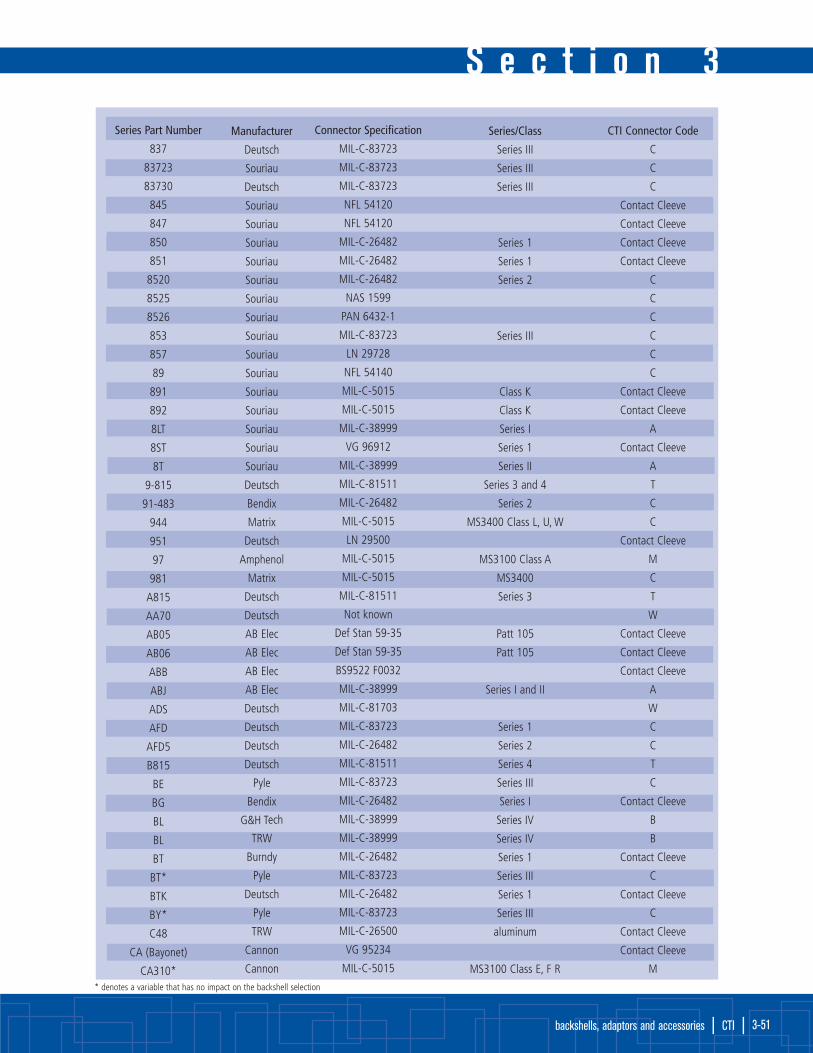
S e c t i o n 3
backshells, adaptors and accessories | CTI | 3-51
Series Part Number
837
83723
83730
845
847
850
851
8520
8525
8526
853
857
89
891
892
8LT
8ST
8T
9-815
91-483
944
951
97
981
A815
AA70
AB05
AB06
ABB
ABJ
ADS
AFD
AFD5
B815
BE
BG
BL
BL
BT
BT*
BTK
BY*
C48
CA (Bayonet)
CA310*
Connector Specification
MIL-C-83723
MIL-C-83723
MIL-C-83723
NFL 54120
NFL 54120
MIL-C-26482
MIL-C-26482
MIL-C-26482
NAS 1599
PAN 6432-1
MIL-C-83723
LN 29728
NFL 54140
MIL-C-5015
MIL-C-5015
MIL-C-38999
VG 96912
MIL-C-38999
MIL-C-81511
MIL-C-26482
MIL-C-5015
LN 29500
MIL-C-5015
MIL-C-5015
MIL-C-81511
Not known
Def Stan 59-35
Def Stan 59-35
BS9522 F0032
MIL-C-38999
MIL-C-81703
MIL-C-83723
MIL-C-26482
MIL-C-81511
MIL-C-83723
MIL-C-26482
MIL-C-38999
MIL-C-38999
MIL-C-26482
MIL-C-83723
MIL-C-26482
MIL-C-83723
MIL-C-26500
VG 95234
MIL-C-5015
Series/Class
Series III
Series III
Series III
Series 1
Series 1
Series 2
Series III
Class K
Class K
Series I
Series 1
Series II
Series 3 and 4
Series 2
MS3400 Class L, U, W
MS3100 Class A
MS3400
Series 3
Patt 105
Patt 105
Series I and II
Series 1
Series 2
Series 4
Series III
Series I
Series IV
Series IV
Series 1
Series III
Series 1
Series III
aluminum
MS3100 Class E, F R
Manufacturer
Deutsch
Souriau
Deutsch
Souriau
Souriau
Souriau
Souriau
Souriau
Souriau
Souriau
Souriau
Souriau
Souriau
Souriau
Souriau
Souriau
Souriau
Souriau
Deutsch
Bendix
Matrix
Deutsch
Amphenol
Matrix
Deutsch
Deutsch
AB Elec
AB Elec
AB Elec
AB Elec
Deutsch
Deutsch
Deutsch
Deutsch
Pyle
Bendix
G&H Tech
TRW
Burndy
Pyle
Deutsch
Pyle
TRW
Cannon
Cannon
CTI Connector Code
C
C
C
Contact Cleeve
Contact Cleeve
Contact Cleeve
Contact Cleeve
C
C
C
C
C
C
Contact Cleeve
Contact Cleeve
A
Contact Cleeve
A
T
C
C
Contact Cleeve
M
C
T
W
Contact Cleeve
Contact Cleeve
Contact Cleeve
A
W
C
C
T
C
Contact Cleeve
B
B
Contact Cleeve
C
Contact Cleeve
C
Contact Cleeve
Contact Cleeve
M
* denotes a variable that has no impact on the backshell selection

backshells, adaptors and accessoriesbackshells, adaptors and accessoriesS e c t i o n 3
| CTI | www.cleevetech.com 3-52
CTI Connector Code by Manufacturer’s Prefix
Series Part Number
CA310*
CA310*KE
CIR
CN0930
CT
CT
CV-R
CV34
CVA
CWL
CWLD
D817
DA
DBAD
DBAS
DD
DFE
DKM
DL
DM
DPX
DS
DTS
EA
EB
EEG
ES
ES0004
ET
FAE3470
FAE3474
FAE3475
FAE20
FAE24
FAE26
FC
FDBA
FF
FH
FPK
FP5K
FYL
Connector Specification
MIL-C-5015
MIL-C-5015
VG 95234
MIL-C-83723
MIL-C-38999
MIL-C-38999
MIL-C-83723
MIL-C-5015
MIL-C-83723
None
MIL-C-22992
MIL-C-81703
None
MIL-C-81703
MIL-C-81703
MIL-C-81703
MIL-C-26482
VG 95328
MIL-C-83723
MIL-C-81703
None
MIL-C-38999
None
NAS 1599
MIL-C-83723
None
MIL-C-5015
NAS1599
M26482
M26482
M26482
D38999
D38999
D38999
MIL-C-5015
LN 29504
MIL-C-5015
MIL-C-83723
MIL-C-26500
MIL-C-26500
MIL-C-26500
Series/Class
MS3100 Class A
Class K
Series III
Series II
Series II
Series II
MS3400 Class L, U, W
Series II
Class C, J, R
Series 3
Series 3
Series 2
Series 2
Series III
Series 1
Series III
Series I
Class K
Series 2
Series 2
Series 2
Series III
Series III
Series III
Rev E only
MS3400 Class D, L, U, W
Series III
Class K
Class K
Class K
Manufacturer
Cannon
Cannon
VEAM
TRW
Burndy
Plessey
Cannon
Cannon
Cannon
Cannon
Cannon
Deutsch
Deutsch
Deutsch
Deutsch
Deutsch
Deutsch
Deutsch
Deutsch
Deutsch
Cannon
Deutsch
Deutsch
Pyle
Pyle
Pyle
Pyle
Various
Pyle
CTI
CTI
CTI
CTI
CTI
CTI
Flight
Deutsch
Flight
Flight
Pyle
Pyle
Pyle
CTI Connector Code
M
Contact Cleeve
Contact Cleeve
C
A
A
S
C
S
Contact Cleeve
Contact Cleeve
C
W
Contact Cleeve
C
W
C
Contact Cleeve
C
W
Contact Cleeve
W
B
C
C
C
C
Contact Cleeve
C
C
C
C
B
B
B
Contact Cleeve
C
C
C
Contact Cleeve
Contact Cleeve
Contact Cleeve
* denotes a variable that has no impact on the backshell selection

S e c t i o n 3
backshells, adaptors and accessories | CTI | 3-53
Series Part Number
G
GC-E
GTA
HAN
HD
HTMAS
HTMF
HTMS
JT
JT
JT
JT-R
JT-R
KFS
KJ
KJA
KJJ
KJJL
KJL
KPSE
KPT
KV-R
L
LJT
LJT
LL3
LL5/6
LMB
LPT
LS
LTT
M-T
M723
MB1
MB3
MB9
MD
MDR
MF
MK12
MK18
MK38
MK25
MK7
MK8
Connector Specification
None
MIL-C-26482
MIL-C-28840/*
MIL-C-5015
MIL-C-28840
MIL-C-5015
MIL-C-83723
MVEE 695
MIL-C-38999
MIL-C-38999
MIL-C-38999
PAN 6433-1
PAN 6433-1
MIL-C-28840
MIL-C-38999
MIL-C-38999
MIL-C-38999
MIL-C-38999
MIL-C-38999
MIL-C-26482
MIL-C-26482
NAS 1599
MIL-C-26482
MIL-C-38999
MIL-C-38999
MIL-C-81511
BS9540 F0001
Def Stan 59-35
MIL-C-26482
None
BS9522 F0029
MIL-C-26482
MIL-C-83723
MIL-C-26482
MIL-C-83723
MIL-C-38999
MIL-C-26482
None
MIL-C-83723
Def Stan 59-35
Def Stan 59-35
MIL-C-38999
MIL-C-38999
DEF 5325-2
Def Stan 59-35
Series/Class
Series 1
MS3100 Class E, KE
Class K
Series Ill: Class K
Series II
Series II
Series II
Series II
Series III
Series II
Series I
Series I
Series 1
Series 1
Series 1
Series 1
Series I
Patt 602
Patt 121A
Series 1
Patt 616
Series 1
Series II
Series 2
Series III
Series I and II
Series 2
Series III
Patt 603
Patt 608
Series I
Series II
Patt 104
Patt 105
Manufacturer
Burndy
General
Hughes
Deutsch
SAE
Cannon
Cannon
AB Elec
Amphenol
Bendix/FKI
Socapex
FKI
Teldix
Cannon
Cannon
Cannon
Cannon
Cannon
Cannon
Cannon
Cannon
Cannon
Burndy
Bendix
Socapex
Deutsch
Deutsch
Litton-Veam
Deutsch
Pyle
FKI
Burndy
Matrix
Matrix
Matrix
Matrix
Matrix
Deutsch
Cannon
Plessey
Plessey
Plessey
Plessey
Plessey
Plessey
CTI Connector Code
Contact Cleeve
Contact Cleeve
F
Contact Cleeve
F
Contact Cleeve
C
X
A
A
A
A
A
F
A
B
Contact Cleeve
Contact Cleeve
A
Contact Cleeve
Contact Cleeve
C
Contact Cleeve
A
A
T
Contact Cleeve
X
Contact Cleeve
C
A
Contact Cleeve
S
C
C
A
C
W
C
Contact Cleeve
Contact Cleeve
A
A
Contact Cleeve
Contact Cleeve* denotes a variable that has no impact on the backshell selection

backshells, adaptors and accessoriesbackshells, adaptors and accessoriesS e c t i o n 3
| CTI | www.cleevetech.com 3-54
CTI Connector Code by Manufacturer’s Prefix
Series Part Number
ML94
MQ3
MT3
MT93
P5
PAT104D
PT
PT
PT-CE
PT-G
PT-SE
PT-SE
PT07
PT07SE
PT33
PT33SE
PT44
PT44SE
PT55
PT55SE
PT77
PT77SE
PTG55
PTG55SE
PTS-DR
PV7*
PVJ
PVW
PVX
QDP
QRP
QWL
QWLD
RD1
RR
RR20
RR50
RR70
RSM
RTK
SA
SB
Connector Specification
MIL-C-38999
MIL-C-83723
MIL-C-83723
MIL-C-38999
NFL 54 125
Def Stan 59-35
MIL-C-26482
MIL-C-26482
None
VG 95328
MIL-C-26482
MIL-C-26482
MIL-C-26482
MIL-C-26482
BS9522 F0017
BS9522 N0001
BS9522 F0017
BS9522 N0001
BS9522 F0017
BS9522 N0001
BS9522 F0017
BS9522 N0001
BS9522 F0017
BS9522 N0001
MIL-C-26482
MIL-C-26482
MIL-C-26482
Def Stan 59-56
None
None
MIL-C-22992
MIS-20065
Def Stan 59-56
PAN 6432-2
PAN 6432-1
PAN 6432-2
None
None
MIL-C-5015
MIL-C-5015
Series/Class
Series IV
Series III
Series III
Series III
Patt 104
Series 1
Series 1
Series 1
Series 1
Series 1
Series 1
Patt 105
Patt 603
Patt 105
Patt 603
Patt 105
Patt 603
Patt 105
Patt 603
Patt 105
Patt 603
Series 2
Series 2
Series 2
Patt 602
Class C, J, R
Patt 602
MS3400
Class E
Manufacturer
Matrix
Matrix
Matrix
Matrix
Plessey
AB Elec
Socapex
Teldix
Bendix
Teldix
Socapex
Teldix
Bendix
FKI
FKI
FKI
FKI
FKI
FKI
FKI
FKI
FKI
FKI
FKI
Bendix
Cannon
Cannon
Cannon
Cannon
Bendix
AB Elec
Bendix
Bendix
Raychem
Deutsch
Deutsch
Deutsch
Deutsch
Deutsch
Deutsch
SAE
Bendix
CTI Connector Code
B
C
C
B
Contact Cleeve
Contact Cleeve
Contact Cleeve
Contact Cleeve
Contact Cleeve
Contact Cleeve
Contact Cleeve
Contact Cleeve
Contact Cleeve
Contact Cleeve
Contact Cleeve
Contact Cleeve
Contact Cleeve
Contact Cleeve
Contact Cleeve
Contact Cleeve
Contact Cleeve
Contact Cleeve
Contact Cleeve
Contact Cleeve
C
C
C
C
C
V
Contact Cleeve
Contact Cleeve
V
C
C
C
C
C
W
W
C
M
* denotes a variable that has no impact on the backshell selection

S e c t i o n 3
backshells, adaptors and accessories | CTI | 3-55
* denotes a variable that has no impact on the backshell selection
Series Part Number
SB104
SB-M4
SB-MS
SC
SCB
SF
SG
SJT
SJT07
SLPT
SM
SPT
SPT
SPT07
STK
STT
STT07
T3*
TRIM TRIO
TT
TV
TV-O-R
TVP
TVPS
TVS
Tri-Start
VPT
VTT
ZZY/ZZW
ZZY/ZZW
Connector Specification
Def Stan 59-35
Def Stan 59-35
BS9522 F0030
MIL-C-5015
VG 95234
MIL-C-5015
MIL-C-5015
PAN 6433-2
PAN 6433-2
MIL-C-26482
MIL-C-5015
MIL-C-26482
MIL-C-26482
MIL-C-26482
None
BS9522 F0012
BS9522 F0012
MIL-C-38999
None
BS9522 N0003
MIL-C-38999
MIL-C-38999
MIL-C-38999
MIL-C-38999
MIL-C-38999
MIL-C-38999
MIL-C-26482
MIL-C-38999
MIL-C-26500
MIL-C-26500
Series/Class
Patt 104
Patt 104
MS3100 Class A
MS3100 Class E
MS3100 Class E
Series 1
MS3100 Class A, E, R
Series 1
Series 1
Series 1
Patt 615
Patt 615
Series III
Patt 614
Series III
Series III and IV
Series III
Series III
Series III
Series III and IV
Series 1
Series III
Class R, G (AL)
Class E (SST)
Manufacturer
AB Elec
AB Elec
AB Elec
Bendix
SICEM
Bendix
Bendix
Various
Various
Deutsch
Bendix
Bendix
Socapex
Various
Deutsch
FKI
FKI
Pyle
Burndy
FKI
FKI/Bendix
Bendix
FKI/Bendix
FKI/Bendix
FKI/Bendix
Bendix
VEAM
FKI
Pyle
Pyle
CTI Connector Code
Contact Cleeve
Contact Cleeve
X
M
Contact Cleeve
M
M
Contact Cleeve
Contact Cleeve
Contact Cleeve
M
Contact Cleeve
Contact Cleeve
Contact Cleeve
W
Contact Cleeve
Contact Cleeve
B
Contact Cleeve
A
B
B
B
Contact Cleeve
Contact Cleeve
B
Contact Cleeve
B
Contact Cleeve
Contact Cleeve

heat shrink molded partsheat shrink molded partsS e c t i o n 4
| CTI | www.cleevetech.com 4-56
CTI’s Heat Shrinkable Molded Partsprovide dependable strain relief and mechanical and electrical protection for a wide
range of applications and environmental conditions.
Performance advantages include the following:
• Abrasion and crush resistance
• Excellent performance at high and low temperatures
• Superior mechanical protection
• Sealing and strain relief
• Compliance with MIL-I-81765, the American Bureau of Shipping (ABS), Lloyd’sRegistry of Shipping, and Det Norske Veritas (DNV) standards.
Broad range of configurations. CTI’s molded parts, boots, cable breakouts,
transitions, covers, caps, and feedthroughs come in a variety of configurations
and sizes.
They are also available in a variety of materials:• Semirigid and flexible polyolefin (PL and PF)
• Modified elastomer (EL)
• Zero Halogen (ZH)
• Viton® polymer blend (VL)
Applications: CTI molded parts are versatile and can offer cost-effective
solutions in many application areas, including military, aerospace, rail, mass transit,
automotive and truck, heavy equipment, and marine.
Heat shrinkable transitions for breakouts and junctions. Heat
shrinkable transitions together with adhesives are used to provide strain relief,
environmental sealing and mechanical protection wherever there is a junction or
breakout in a cable harness. Transitions are available for forming multiple breakout
configurations. They are supplied in an expanded form which easily allows cable
bundles to be fed through the transitions prior to shrinking. For mechanical strength
and sealing, transitions need to be installed with an adhesive at each interface.
Adhesive options available are pre-coated to molded parts or as separate adhesives
in hot melt or epoxy systems.
Transition selection guide:
1. Select the transition series from the table;
2. Determine the diameter of the harness at each leg of the junction breakout. The
cable bundle may be calculated from information the following pages;
3. Select the transition size from the information sheets to follow. The largest tran-
sition for a particular application should be chosen as this will give the largest
wall thickness providing the optimum mechanical protection and strain relief.

Transition series:
Name Series Part Number
T Transition FMP301A0XX
FMP322A1XX
45° side breakout FMP342A0XX
Y transition FMP382A0XX
1 into 3 breakout FMP462A0XX
1 into 4 breakout FMP562A0XX
These transitions can be supplied pre-coated with adhesive. The adhesive designator is detailed in the pages following.
Undersized cable. When choosing a transition it may be that, having determined the optimum transition, one of the legs is
slightly undersize. This can be built up to the correct diameter by using a packing sleeve. A packing sleeve is a cut piece of tubing
that is installed underneath the cable jacket. Adhesive should also be used in order to ensure a sealed assembly.
Example: A harness requires a breakout to be installed. From the table the relevant series is FMP382A0XX. The three cable legs
are (over the braid) 14 mm, 4 mm, and 6 mm. The choice of tubing to be installed on each leg would be as follows (the wall
thickness calculated as the example below):
The optimum part is FMP382A023 which in the main branch recovers from 27 mm to 12.4 mm and has two legs of 13 mm
recovering to 6.1 mm. Cable 2 is too small to fit the 6.1 mm leg. By installing a 25 mm piece of tubing 1/4” as a package piece
at the transition and then installing the tubing 1/4” over the whole cable length the final cable OD will be:
5.34 + 2(0.53) = 6.4 mm (this will then provide a diameter large enough for the FMP382A023)
S e c t i o n 4
heat shrink molded parts | CTI | 4-57
Cable Wire bundle Tubing size Wall thickness Finished
(mm) (in) (mm) (in)
1 14 1 1.5 17.0
2 4 1/4 0.67 5.34
3 6 3/8 0.75 7.50

FMP301A011 to 048 Transition TMaterials available:
• EL Fluid resistant modified elastomer
• VL Modified fluoroelastomer
• ZH Low fire hazard material
• PL Semi-rigid modified polyolefin
• PF Flexible modified polyolefin
Coatings: See chart at bottom of page
heat shrink molded partsheat shrink molded partsS e c t i o n 4
| CTI | www.cleevetech.com 4-58
Table of Dimensions apply to all materials unless otherwise indicated
dimensions (mm): Expanded as supplied (min) Recovered after heating (max)
H J K H J K P R
FMP301A011 7 7 7 3.6 3.6 3.6 30 15
FMP301A022 13 13 13 6.9 6.9 6.9 59 30
FMP301A034 27 27 27 13.5 13.5 13.5 120 60
FMP301A048 56 56 56 30.2 30.2 30.2 246 123
Table of Dimensions apply to all materials unless otherwise indicated
dimensions (mm): Expanded as supplied (min) Recovered after heating (max)
H J K H J K P R S
FMP322A112 13 13 7 5.8 5.8 3.0 52 26 19
FMP322A123 27 27 7 12.4 12.4 3.0 83 42 27
FMP322A134 27 27 13 12.7 12.7 5.8 108 54 39
FMP322A148 56 56 13 25.4 25.4 5.8 181 90 57
FMP322A158 56 56 27 25.4 25.4 12.4 222 111 78
FMP322A112 to 158 90° Side Breakout TransitionMaterials available:
• EL Fluid resistant modified elastomer
• VL Modified fluoroelastomer
• ZH Low fire hazard material
• PL Semi-rigid modified polyolefin
• PF Flexible modified polyolefin
Coatings: See chart at bottom of page
Coatings: Material Available coatings:
EL WA High performance
WA Curing adhesive
ZH WA High performance hot melt adhesive
PL WA High performance hot melt adhesive
PF WA General purpose hot melt adhesive
VL Not available adhesive coated

S e c t i o n 4
heat shrink molded parts | CTI | 4-59
FMP342A012 to 058 45° Side Breakout TransitionMaterials available:
• EL Fluid resistant modified elastomer
• VL Modified fluoroelastomer
• ZH Low fire hazard material
• PL Semi-rigid modified polyolefin
• PF Flexible modified polyolefin
Coatings: See chart at bottom of page
Table of Dimensions apply to all materials unless otherwise indicated
dimensions (mm): Expanded as supplied (min) Recovered after heating (max)
H J K H J K P R S
FMP342A012 13 13 7 6.9 6.9 3.6 49 23 23
FMP342A024 27 27 7 12.7 12.7 3.6 93 41 36
FMP342A034 27 27 13 13.7 3.7 7.4 145 70 54
FMP342A048 56 56 13 26.9 26.9 6.9 185 83 72
FMP342A058 56 56 27 26.9 26.9 13.7 204 96 93
Table of Dimensions apply to all materials unless otherwise indicated
dimensions (mm): Expanded as supplied (min) Recovered after heating (max)
H J K H J K P R
FMP382A012 13 7 7 6.1 3.3 3.3 22 19
FMP382A024 27 13 13 12.4 6.1 6.1 38 43
FMP382A034 39 27 27 18.0 12.4 12.4 66 82
FMP382A046 56 27 27 25.9 12.7 12.7 85 94
FMP382A012 to 046 Transition YMaterials available:
• EL Fluid resistant modified elastomer
• VL Modified fluoroelastomer
• ZH Low fire hazard material
• PL Semi-rigid modified polyolefin
• PF Flexible modified polyolefin
Coatings: See chart at bottom of page
Coatings: Material Available coatings:
EL WA High performance
WA Curing adhesive
ZH WA High performance hot melt adhesive
PL WA High performance hot melt adhesive
PF WA General purpose hot melt adhesive
VL Not available adhesive coated

heat shrink molded partsheat shrink molded partsS e c t i o n 4
| CTI | www.cleevetech.com 4-60
FMP562A011 to 067 Transition 1 into 4 CablesMaterials available:
• EL Fluid resistant modified elastomer
• VL Modified fluoroelastomer
• ZH Low fire hazard material
• PL Semi-rigid modified polyolefin
• PF Flexible modified polyolefin
Coatings: See chart at bottom of page
Coatings: Material Available coatings:
EL WA High performance
WA Curing adhesive
ZH WA High performance hot melt adhesive
PL WA High performance hot melt adhesive
PF WA General purpose hot melt adhesive
VL Not available adhesive coated
Table of Dimensions apply to all materials unless otherwise indicated
dimensions (mm): Expanded as supplied (min) Recovered after heating (max)
H J K L N H J K L N P R S C° D°
FMP562A011 13 7 7 7 7 6.9 3.6 3.6 3.6 3.6 24 38 24 45 15
FMP562A022 19 9 9 9 9 9.7 5.3 5.3 5.3 5.3 36 36 32 45 15
FMP562A032 19 13 13 13 13 9.7 6.9 6.9 6.9 6.9 49 36 45 45 15
FMP562A043 27 13 13 13 13 13.0 6.9 6.9 6.9 6.9 49 52 45 45 15
FMP562A054 39 19 19 19 19 18.5 9.7 9.7 9.7 9.7 72 75 65 45 15
FMP562A067 56 27 27 27 27 26.7 13.0 13.0 13.0 13.0 102 109 93 45 15
FMP462A011 to 60 Transition 1 into 3 CablesMaterials available:
• EL Fluid resistant modified elastomer
• VL Modified fluoroelastomer
• ZH Low fire hazard material
• PL Semi-rigid modified polyolefin
• PF Flexible modified polyolefin
Coatings: See chart at bottom of page
Table of Dimensions apply to all materials unless otherwise indicated
dimensions (mm): Expanded as supplied (min) Recovered after heating (max)
H J K L H J K L P R S C
FMP462A011 13 7 7 7 6.6 3.6 3.6 3.6 46 25 21 30
FMP462A023 27 13 13 13 13.2 6.9 6.9 6.9 93 50 43 30
FMP462A034 39 19 19 19 18.8 9.7 9.7 9.7 135 74 62 30
FMP462A046 56 27 27 27 25.4 12.4 12.4 12.4 192 103 89 30
FMP462A060 91 46 46 46 54.6 27.4 27.4 27.4 390 211 179 30

S e c t i o n 4
heat shrink molded parts | CTI | 4-61
CTI’s Heat Shrinkable Molded Parts Shapes and Boots provide mechanical and electrical protection, strain relief and
dependable environmental sealing for a wide range of applications and environmental conditions.
Available in a wide range of material options for your specific application and pre-coated with a high performance adhesive system (if
required). CTI heat shrinkable molded parts offer:
• Abrasion and crush resistance;
• Sealing and strain relief;
• Compliance with numerous military, defence and industrial standards and specifications;
• Wide range of shapes and configurations including boots, cable breakouts, transitions, covers, caps, and feedthroughs;
• All in a wide variety of configurations and sizes.
CTI molded parts are versatile and can offer cost-effective solutions in many application areas, including military, aerospace, rail and
mass transit, automotive and truck, heavy equipment, and marine.

heat shrink molded partsheat shrink molded partsS e c t i o n 4
| CTI | www.cleevetech.com 4-62
Connector BootsCTI heat shrinkable boots are used to provide strain relief, mechanical protection and environmental sealing from the cable
jacket to connector. CTI offers many types of Molded shapes. The choice depends on the application, repair considerations
and the screening required. For more detailed information on the Molded parts discussed here refer to the ‘Molded Parts Product
Guide’.
Boot Selection Chart: In the table on page 3-44 the recommend-ed boots are detailed for each adaptor for a particular connector code.The boots are recommended for the entry size of the adaptor. Once thepart number has been determined the material suffix must be added.
The cable range stated in the table refers to the fully recovered bootdimensions.
Molded Part Type Description Typical Part NumberingChoice Table Application Straight Right Angle
Standard K boots
Uni-boots
Low profile boots
The most commonly used heatshrinkable boot to terminate cablesat connectors. This boot providessufficient room for repair loops. Byreheating, the boot can be rolledback allowing access for repair
- Military ground vehicles - Communications equipment
FMP222K1XXFMP202K1XX
FMP222D1XXFMP202D1XX
FMP202C6XX
- Open wire bundles in aircraft application
- Military ground vehicles - Communication equipment- Marine
A flexible boot which can beformed to the desired angle. Thepart can be equipment compressedto effect repair
These boots conform closely to theadaptor shape. They are normallyused on open-wire cable bundles
PartNumberingSystem
FMP202K1 32 - EL - 01 / WA
Adhesive coating selected for compatibility with molded part materialGeneral purpose hot melt High performance hot melt Pre-coated curing adhesive
Modification code
Material selectionEL Fluid resistance elastomer ZH Low fire hazard material VL Modified fluoroelastomerPL Semi-rigid polyolefin PF Flexible polyolefinPS Low outgassing polyolefinEB Fluid resistant elastomer (uni-boots only) PB Semi-rigid polyolefin (uni-boots only)
Comparative size
Product family

S e c t i o n 4
heat shrink molded parts | CTI | 4-63
Sample Drawings: Heat Shrink Molded Parts

What is Heat Shrink Tubing?
Heat shrink tubing is commonly referred to by several different names, including: shrink wrap, shrink band, shrink tubing, heat
shrink sleeve and heat shrinkable tubing.
Typical applications include: electrical insulation, termination, splicing, cable bundling, colour coding, strain relief, wire marking,
identification, mechanical protection, corrosion protection, abrasion protection, strain relief, wire and cable management and
moisture and weather sealing.
Heat shrinkable tubing is manufactured in one size and then supplied in the ‘expanded’ state. Upon the application of heat, it will
shrink down to its originally manufactured size (usually the size it is supplied in, which would make it a 2 to 1 shrink ratio) but
in some cases the expansion may be greater. Common types include 3 to1 and 4 to 1 but ratios as large as 6 to 1 are also avail-
able. Some options are supplied with an adhesive inner lining which will flow and seal like an adhesive as part of the
installation process (also know as dual wall heat shrink tubing).
When the heat shrink tube is supplied in an expanded state, it has ‘memory’. This means that when it is exposed to high heat
(commonly referred to as the shrink temperature or activation temperature), it will ‘shrink’ back to its original diameter. This is
called the recovered state. Unless stated otherwise, the diameter listed and ordered is the expanded diameter. Also, the diameter
is measured as a tube, not the flat width.
There are many ways to shrink heat shrink tubing. Usually a hair dryer will not work. A cigarette lighter will work, but may cause
charring to the tubing. In most cases a hot air oven or a heat shrink gun (available from CTI) is the ideal heat source. In special
cases a blow torch may be used.
CTI offers many varieties of heat shrink tubing, such as: polyolefin, fluoropolymer, elastomers and neoprenes (like rubber) each
selected based on the performance needs and application.
CTI tubing conforms to all major commercial and military specifications and is available to specific manufacturer’s part
numbers, to the applicable military specification part number or to a CTI part number.
Materials are available in thin wall, medium wall or heavy wall configurations, with melt-and-flow adhesives, weather proofing
encapsulants, and in many different colours, lengths and packaging options.
Custom cutting and printing services are also available upon request.
tubing, EMI shielding, conduit & protective sleevingtubing, EMI shielding, conduit & protective sleevingS e c t i o n 5
| CTI | www.cleevetech.com 5-64

CTI Heat Shrink Tubing Heat Shrink PVC
S e c t i o n 5
tubing, EMI shielding, conduit & protective sleeving | CTI | 5-65
Description CTI Specifications Approvals
Standard wall M053-2C2 (Class 2) UL VW-1 & CSA OFT
1/32" wall UL VW-1 & CSA OFT
Irradiated M053-2C1 (Class 1) UL VW-1 & CSA OFT
Lay flat
Heat Shrink Polyolefin (with and without inner adhesive or meltable lining)
Description CTI Specifications Approvals
Standard wall M053-5C1 (Class 1) also Class 2 and Class 3 UL VW-1 & CSA OFT
Very flexible R46846 Type 5 UL & CSA
Thin wall M053-5TW UL VW-1 & CSA OFT
Semi-rigid M053-6C1 (Class 1) also Class 2 UL
Meltable inner wall M053-4C1 (Class 1)
Adhesive lined M053-4C2 (Class 2) also Class 3
Heavy wall adhesive lined M053-15C1 (Class 1) also Class 2
Heat Shrink Teflon
Description CTI Specifications Approvals
TFE M053-12C1, also Class 2, Class 3, Class 4 and Class 5
FEP M053-11C1 (Class 1) also Class 2
Heat Shrink Kynar®
Description CTI Specifications Approvals
Kynar® M053-8 UL VW-1 & CSA OFT
Heat Shrink Mylar®
Description CTI Specifications Approvals
Mylar® M23053-7C2 (Class 2)
Heat Shrink Neoprene and Elastomer
Description CTI Specifications Approvals
Neoprene M053-1C1 (Class 1) also Class 2
Elastomer M053-16
Heat Shrink Viton® and Silicon Rubber
Description CTI Specifications Approvals
Viton® M053-13
Silicon Rubber M053-10

tubing, EMI shielding, conduit & protective sleevingtubing, EMI shielding, conduit & protective sleevingS e c t i o n 5
| CTI | www.cleevetech.com 5-66
Other Shrinkable Tubing Available Upon Request Non-Shrink Tubing Teflon
Description CTI Specifications Approvals
TFE M22129C
FEP
Non-Shrink Tubing PVC
Description CTI Specifications Approvals
Standard wall M631D Grade C UL VW-1 & CSA OFT
1/32" wall UL VW-1 & CSA OFT
Fractional wall FDA Grade
Low temperature M7444 Type 1 & 3
Non-Shrink Tubing Sleeving
Description CTI Specifications Approvals
Heat treated fiberglass UL
Vinyl coated fiberglass M3190 UL
Acrylic coated fiberglass M3190 UL
Silicone coated fiberglass M3190 UL
Expandable polyester
Non-Shrink Tubing Special Services
Description CTI Specifications
Hot stamp marking MIL-M-81531
Cutting to length
Special packaging/kitting
Example of full part number: M053-5C1 - 1/2 - 9
Material description
Size
Colour

CTI Protective Sleeving
CTI protective sleeving, tubing and conduits are available in many options, from material types and constructions, sizes, lengths, colours
and operating performance through to qualification and approval levels, and are most often used for:
• Thermal protection • Electrical protection/sleeving • General purpose • Heat shrink
• Packaging • Identification • Mechanical-abrasion protection
Overview of product options available:
ProtectaSleeve F: High temperature fire sleeves protect hoses, lines, cables and wires in areas of extreme heat, guard personnel
from burns, and cut costly energy losses. Under the heavy coating of silicone rubber is a braided interior layer.
ReflectaSleeve: Performance tested at 3000°F (1650°C) for 1 minute, ReflectaSleeve reflects at least 90% of radiant heat energy.
ProtectaSleeve W: Heavy-wall braided fiberglass sleeve offers economical hose and cable protection where exposure to moisture,
oils or molten splash is not a factor.
ProtectaGuard: Nylon woven design provides ultimate abrasion protection. Treated with heat and flame resistant coating, acts as a
protective barrier/shield ensuring operator safety. Expandable braided sleeving is very similar a woven ‘stocking’ and when you push the
end back, the sleeving expands to go over wires or other substrates easily, and then when you let go, the sleeving comes back to its
original diameter (or the diameter of your wire harness or bundle, whichever is larger).
Polyethylene Terephthalate (PET) braided sleeving is the most widely used expandable braided sleeve. It is commonly referred to
as ‘General Purpose’ (GP). In many cases, sleeving referred to as Nylon is actually polyester. While Nylon monofilaments do provide
better abrasion resistance in some cases, it also costs 40-60% more than PET, and may be of a higher performance than required in
many applications.
While the braiding process can be controlled to regulate the expandability of the final braid, most expandable PET braided sleeving
supplied today is made in a standard construction that before further processing, varies very little between manufacturers. Standard
braids can expand up to 2 times their nominal size, allowing for easy installation in complex wiring harnesses, and a high degree of
flexibility in the size used.
There are a few different types of fray resistant braided sleeves also available. One type has a resin applied to the braid causing the
individual filaments to stick to each other. Other types consist of a tighter braid, causing the braid to fray less than normal when cut
with scissors.
S e c t i o n 5
tubing, EMI shielding, conduit & protective sleeving | CTI | 5-67

tubing, EMI shielding, conduit & protective sleevingtubing, EMI shielding, conduit & protective sleevingS e c t i o n 5
| CTI | www.cleevetech.com 5-68
General Installation Instructions for CTI Heat Shrink Products: Select the largest sizeof tubing that will still fit snugly after shrinking, according to the shrink ratio of the product beingused (e.g. for 2:1 products select approximately twice the diameter). Cut tubing to the exact lengthrequired (i.e. no shrinkage in length) with a clean, square cut to avoid splitting.
Position tubing over object and heat evenly until tubing shrinks into place or will shrink no further.Products containing pre-installed adhesive may need extra heat to melt and flow the adhesive forproper application.
Keep the heat source or product moving, so the heat is not concentrated in one spot. Keep the heatsource at least one inch away from tubing, using a low-intensity heat source such as a hot air gun,oven, infrared heat source, or soft (yellow) flame.
Thermafix® 2:1 3/64 to 4 No -30˚C to 125˚C CSA (LR31929) Black, Very flexibleSingle Wall -22˚F to 257˚F MIL-I-23053/5 White,Polyolefin Tubing (Class 1) Red,
UL (E35586) Yellow,Blue,
Green,Orange,Violet,Grey
Thermafix® 2:1 3/64 to 4 No -55˚C to 135˚C MIL-I-23053/5 Clear FlexibleSingle Wall -67˚F to 275˚F (Class 2)Polyolefin (Clear)
Thermafix Plus™ Dual 4:1 1/4 to 3/4 Yes -40˚C to 130˚C UL (E85381) Black, Semi-rigidWall Polyolefin Tubing -40˚F to 266˚F Clear
Thermafix ST™ Heavy 3:1 0.4 to 4 As Required -55˚C to 90˚C UL(E15664) Black, RigidWall Polyolefin Tubing -67˚F to 194˚F Red
Thermafix DWP™ Dual 3:1 1/8 to 1.5 Yes -40˚C to 110˚C UL (E35586) Black, FlexibleWall Polyolefin Tubing -40˚F to 230˚F CSA (LR31929) Red
Thermafix 3X™ Single 3:1 3/16to 1.5 No -30˚C to 125˚C CSA (LR31929) Black, Very flexibleWall Polyolefin Tubing -22˚F to 257˚F MIL-I-23053/5 White
(Class 1)UL (E35586)
Thermafix DC™ Dual 2:1 1/8 to 1 No -55˚C to 135˚C CSA (LR31929) Yellow/Green FlexibleColour Polyolefin Tubing -67˚F to 275˚F UL (E35586) (Dual Colour)
Thermafix Kynar® 2:1 1/16 to 3/4 No -55˚C to 175˚C CSA (LR31929) Clear Semi-rigidPolyvinylidene Fluoride -67F to 347˚F UL (E35586 VW-1)Tubing MIL-I-23053/8
Thermafix Crimp™ as per 10 to 22 AWG Yes -55˚C to 125˚C UL Red, RigidShrinkable Nylon specified -67˚F to 257˚F C-UL Blue,Terminals and Splices wire gauge (E87681) Yellow
Thermafix SolderSplice™ as per 10 to 22 AWG Partial -30˚C to 125˚C UL (E87681) Red, Semi-rigidShrinkable Polyolefin specified -22˚F to 257˚F Blue,Wire-to-wire wire gauge YellowSplices with Solder
Product Shrink Ratio Sizes (in) Adhesive lined Temp. Range Agency Approval Colours Rigidity
A Quick Guide to CTI Heat Shrink Tubing and Complimentary Products:

S e c t i o n 5
tubing, EMI shielding, conduit & protective sleeving | CTI | 5-69
Braid EMI Pull on Shield SelectionBraids can be supplied on formers to facilitate easy removal and installation on to primary wire that has been laid into a bundle. Four
braid sizes are supplied to cover from 4.5 mm to 39 mm diameter bundles. This product is based on 36 AWG braid and is compatible
with Tinel-lock spin coupling adaptors.
Part number FRB101 Tin-plated copper
FRB103 Nickel-plated copper
Construction Description Cable range Former diameter
(mm) (mm)
7.5 4.5-15.0 7.5
10.0 8.0-22.5 10.0
12.5 10.0-25.0 12.5
20.0 16.0-39.0 20.0
Example: FRB-101-10.0
Tin-plated copper braid with cable range of 8-22.5 mm
Features of PET Braided Sleeving• Excellent cut through and abrasion resistance • Melt temperature of 230°C (446°F)
• Continuous use temperature of -70°C to 125°C (-103°F to 257°F) • Halogen free, ROHS compliant
• Braided from 10 MIL polyethylene terepthalate (PET) monofilament yarns • Self-extinguishing
• Resists gasoline, engine chemicals & cleaning solvents • Expands up to three times its resting diameter
• Registered in the NASA database for low outgassing (under CS technical manufacturer)
• Many colours available
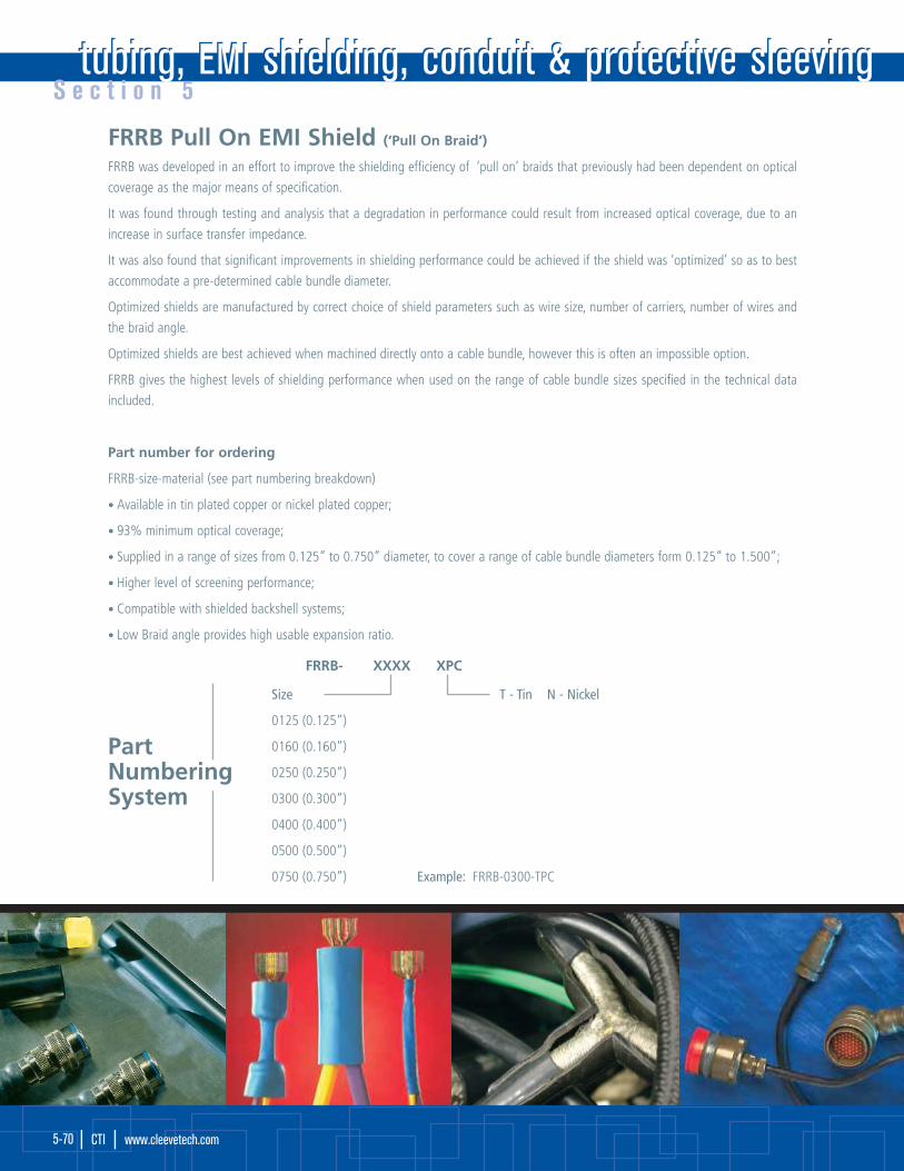
FRRB Pull On EMI Shield (‘Pull On Braid’)
FRRB was developed in an effort to improve the shielding efficiency of ‘pull on’ braids that previously had been dependent on optical
coverage as the major means of specification.
It was found through testing and analysis that a degradation in performance could result from increased optical coverage, due to an
increase in surface transfer impedance.
It was also found that significant improvements in shielding performance could be achieved if the shield was ‘optimized’ so as to best
accommodate a pre-determined cable bundle diameter.
Optimized shields are manufactured by correct choice of shield parameters such as wire size, number of carriers, number of wires and
the braid angle.
Optimized shields are best achieved when machined directly onto a cable bundle, however this is often an impossible option.
FRRB gives the highest levels of shielding performance when used on the range of cable bundle sizes specified in the technical data
included.
Part number for ordering
FRRB-size-material (see part numbering breakdown)
• Available in tin plated copper or nickel plated copper;
• 93% minimum optical coverage;
• Supplied in a range of sizes from 0.125” to 0.750” diameter, to cover a range of cable bundle diameters form 0.125” to 1.500”;
• Higher level of screening performance;
• Compatible with shielded backshell systems;
• Low Braid angle provides high usable expansion ratio.
tubing, EMI shielding, conduit & protective sleevingtubing, EMI shielding, conduit & protective sleevingS e c t i o n 5
| CTI | www.cleevetech.com 5-70
PartNumberingSystem
FRRB- XXXX XPC
Size T - Tin N - Nickel
0125 (0.125”)
0160 (0.160”)
0250 (0.250”)
0300 (0.300”)
0400 (0.400”)
0500 (0.500”)
0750 (0.750”) Example: FRRB-0300-TPC

‘Example of a Tubing Data Sheet’
S e c t i o n 5
tubing, EMI shielding, conduit & protective sleeving | CTI | 5-71
Examples of CTI specification control data sheets available in support of all M053 series heat shrinkable tubing.
Typical Features:
• M053-5V is a very flexible, low recovery temperature, flame-retardant, heat shrinkable polyolefin tubing that is recognized by Underwriters' Laboratories (UL) under Subject 224as UL VW-1, and the Canadian Standards Association (CSA) at 125ºC;
• Low recovery temperature benefits the user in more rapid installation, with less potential damage to heat sensitive component insulation systems;
• Shrink temperature is 90º C, with an indefinite storage life;
• Operating temperature range is -55ºC to +125ºC;
• M053-5V is recommended for all general purpose applications such as insulating, colour coding, bundling and light harness jacketing or environmental protection where UL orCSA recognition as VW-1 rated material is desirable.
Ordering Information:
• Standard colours: Black, white, red, yellow, blue (other colors are available upon request) • How to order: (type of material) (size) (colour)
• Standard package: Spooled (S) or 4 feet (4') Example: M053-5V 1/4” Black
Standard Sizes
Size Inside Diameter Inside Diameter Wall Thickness
As Supplied After Recovery After Recovery
(min) (max) (nom)
(in) (mm) (in) (mm) (in) (mm)
3/64 0.046 1.20 0.023 0.60 0.016 0.40
1/16 0.063 1.60 0.031 0.80 0.017 0.43
3/32 0.093 2.40 0.046 1.20 0.020 0.51
1/8 0.125 3.20 0.062 1.60 0.020 0.51
3/16 0.187 4.80 0.093 2.40 0.020 0.51
1/4 0.250 6.40 0.125 3.20 0.025 0.64
3/8 0.375 9.50 0.187 4.80 0.025 0.64
Standard Sizes
Size Inside Diameter Inside Diameter Wall Thickness
As Supplied After Recovery After Recovery
(min) (max) (nom)
(in) (mm) (in) (mm) (in) (mm)
1/2 0.500 12.70 0.250 6.40 0.025 0.64
3/4 0.750 19.10 0.375 9.50 0.030 0.76
1 1.000 25.40 0.500 12.70 0.035 0.89
1 1/2 1.500 38.10 0.750 19.10 0.040 1.02
2 2.000 50.80 1.000 25.40 0.045 1.14
3 3.000 76.20 1.500 38.10 0.050 1.27
4 4.000 101.60 2.000 50.80 0.055 1.40
M053-5V Heat Shrinkable Polyolefin TubingFlexible Polyolefin, UL/CSA recognized 125°C and 600V (VW-1)
Data Sheet
For further information or additional data sheets please contact us at: Cleeve Technology International Headquarters • [email protected] • www.cleevetech.com
Specification Reference: UL 224 125°C, 600V, VW-1 CSA-C22.2 125°C, 600V
Physical:
Tensile strength (psi)
Elongation (%)
Specific gravity
Low temperature flex (-550°C)
Heat resistance (1580°C, 168 hrs)
Elongation (%)
Secant modulus (psi)
Deformation (125°C, 1 hr) (%)
Longitudinal change (%)
Electrical:
Dielectric withstand (volts)
Volume resistivity (ohm-cm)
Chemical:
Corrosion
Copper stability (158°C 168 hrs)
Elongation (%)
Water absorption (%)
Fluid resistance (230°C, 24 hrs)
Tensile strength (psi)
Flammability
Shrink temperature, nominal
UL 224
UL 224
ASTM D792
AMS-DTL-23053
UL 224
ASTM D882
UL 224
AMS-DTL-23053
UL 224
UL 224
UL 224
UL 224
ASTM D570
AMS-DTL-23053
UL 224 VW-1
1500 min
200 min
1.35 max
No cracking
100 min
25000 min
50 max
+5
2500 min
1.0 X 10¹⁴ min
No corrosion
100 min
0.5 max
1000 min
pass
90°C
Cleeve cage code is 3AN64

tubing, EMI shielding, conduit & protective sleevingtubing, EMI shielding, conduit & protective sleevingS e c t i o n 5
| CTI | www.cleevetech.com 5-72
‘Example of a Tubing Data Sheet’
Typical Features:
• M053-5TW is a very flexible, flame retardant, heat shrinkable polyolefin tubing;
• M053-5TW is available in multiple colours and sizes with white and black being most common;
• Shrink temperature is 90°C. Storage life is indefinite;
• Operating temperature range is -55°C to +135°C;
• M053-5TW is recommended for many applications where protection, colour coding, identification or ‘packaging’ is required.
Ordering Information:
• Standard colours: Black, white, yellow, blue • How to order: (type of material) (size) (colour)
• Standard package: Spooled (S) Example: M053-5TW 1/4” Black
M053-5TW Data SheetFlexible polyolefin, low recovery temperatures.
Data Sheet
Physical:
Tensile strength (psi)
Elongation (%)
Specific gravity
Low temperature flex (-550°C)
Heat resistance (1580°C, 168 hrs.)
Elongation (%)
Secant modulus (psi)
Longitudinal change (%)
Electrical:
Dielectric withstand (volts)
Volume resistivity (ohm-cm)
Chemical:
Heavy metals content
Water absorption
Shrink temperature, nominal
ASTM D638
ASTM D638
ASTM D792
AMS-DTL-23053E
ASTM D638
ASTM D882
AMS-DTL-23053E
ASTM D876
ASTM D876
ASTM D570
1500 min
200 min
1.0 max
No cracking
100 min
25000 min
+5, -15
500 min
1.0 X 10¹⁵ min
<1 ppm
0.2 max
115°C
Standard Sizes
Normal Inside Diameter Inside Diameter Wall Thickness
Size As Supplied (min) After Recovery (max) After Recovery (nom)
(in) (mm) Inch (mm) Inch (mm)
3/64 0.046 1.20 0.023 0.60 0.016 0.40
1/16 0.063 1.60 0.031 0.80 0.017 0.43
3/32 0.093 2.40 0.046 1.20 0.020 0.51
1/8 0.125 3.20 0.062 1.60 0.020 0.51
3/16 0.187 4.80 0.093 2.40 0.020 0.51
1/4 0.250 6.40 0.125 3.20 0.025 0.64
3/8 0.375 9.50 0.187 4.80 0.025 0.64
1/2 0.500 12.70 0.250 6.40 0.025 0.64
For further information or additional data sheets please contact us at: Cleeve Technology International Headquarters • [email protected] • www.cleevetech.com
Cleeve cage code is 3AN64
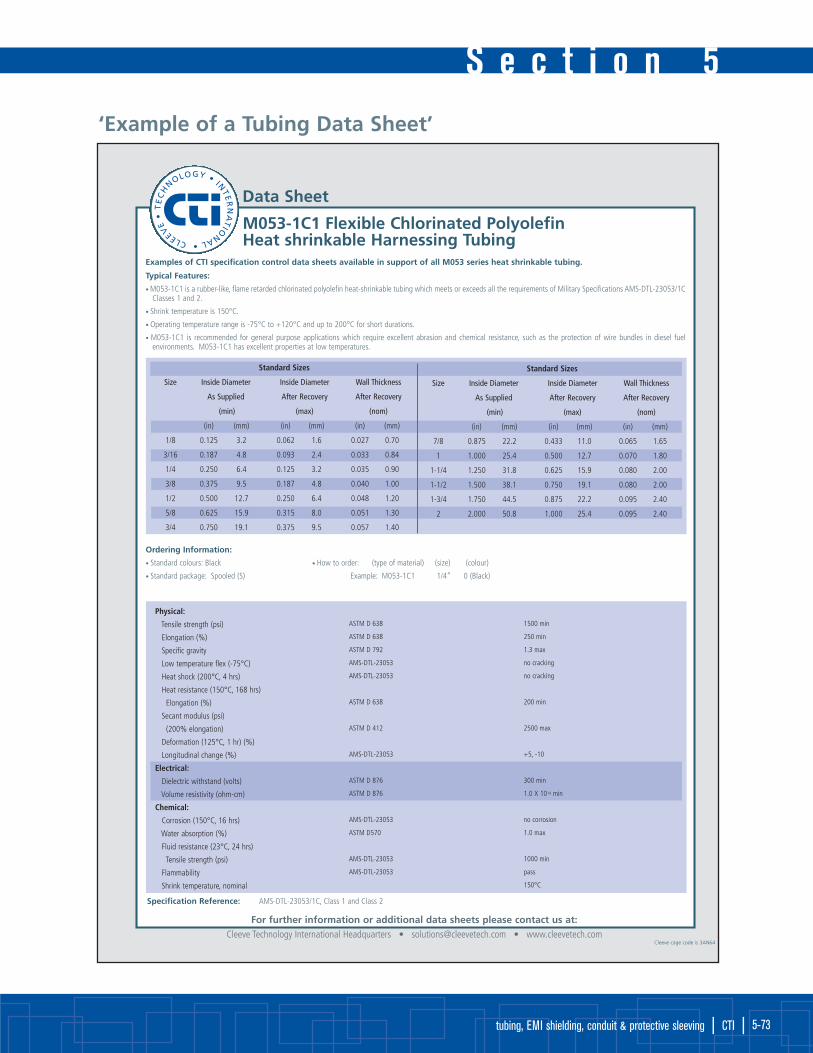
S e c t i o n 5
tubing, EMI shielding, conduit & protective sleeving | CTI | 5-73
‘Example of a Tubing Data Sheet’
Examples of CTI specification control data sheets available in support of all M053 series heat shrinkable tubing.
Typical Features:
• M053-1C1 is a rubber-like, flame retarded chlorinated polyolefin heat-shrinkable tubing which meets or exceeds all the requirements of Military Specifications AMS-DTL-23053/1CClasses 1 and 2.
• Shrink temperature is 150°C.
• Operating temperature range is -75°C to +120°C and up to 200°C for short durations.
• M053-1C1 is recommended for general purpose applications which require excellent abrasion and chemical resistance, such as the protection of wire bundles in diesel fuel environments. M053-1C1 has excellent properties at low temperatures.
Ordering Information:
• Standard colours: Black • How to order: (type of material) (size) (colour)
• Standard package: Spooled (S) Example: M053-1C1 1/4” 0 (Black)
Standard Sizes
Size Inside Diameter Inside Diameter Wall Thickness
As Supplied After Recovery After Recovery
(min) (max) (nom)
(in) (mm) (in) (mm) (in) (mm)
1/8 0.125 3.2 0.062 1.6 0.027 0.70
3/16 0.187 4.8 0.093 2.4 0.033 0.84
1/4 0.250 6.4 0.125 3.2 0.035 0.90
3/8 0.375 9.5 0.187 4.8 0.040 1.00
1/2 0.500 12.7 0.250 6.4 0.048 1.20
5/8 0.625 15.9 0.315 8.0 0.051 1.30
3/4 0.750 19.1 0.375 9.5 0.057 1.40
Standard Sizes
Size Inside Diameter Inside Diameter Wall Thickness
As Supplied After Recovery After Recovery
(min) (max) (nom)
(in) (mm) (in) (mm) (in) (mm)
7/8 0.875 22.2 0.433 11.0 0.065 1.65
1 1.000 25.4 0.500 12.7 0.070 1.80
1-1/4 1.250 31.8 0.625 15.9 0.080 2.00
1-1/2 1.500 38.1 0.750 19.1 0.080 2.00
1-3/4 1.750 44.5 0.875 22.2 0.095 2.40
2 2.000 50.8 1.000 25.4 0.095 2.40
M053-1C1 Flexible Chlorinated Polyolefin Heat shrinkable Harnessing Tubing
Data Sheet
For further information or additional data sheets please contact us at: Cleeve Technology International Headquarters • [email protected] • www.cleevetech.com
Specification Reference: AMS-DTL-23053/1C, Class 1 and Class 2
Physical:
Tensile strength (psi)
Elongation (%)
Specific gravity
Low temperature flex (-75°C)
Heat shock (200°C, 4 hrs)
Heat resistance (150°C, 168 hrs)
Elongation (%)
Secant modulus (psi)
(200% elongation)
Deformation (125°C, 1 hr) (%)
Longitudinal change (%)
Electrical:
Dielectric withstand (volts)
Volume resistivity (ohm-cm)
Chemical:
Corrosion (150°C, 16 hrs)
Water absorption (%)
Fluid resistance (23°C, 24 hrs)
Tensile strength (psi)
Flammability
Shrink temperature, nominal
ASTM D 638
ASTM D 638
ASTM D 792
AMS-DTL-23053
AMS-DTL-23053
ASTM D 638
ASTM D 412
AMS-DTL-23053
ASTM D 876
ASTM D 876
AMS-DTL-23053
ASTM D570
AMS-DTL-23053
AMS-DTL-23053
1500 min
250 min
1.3 max
no cracking
no cracking
200 min
2500 max
+5, -10
300 min
1.0 X 10¹⁴ min
no corrosion
1.0 max
1000 min
pass
150°C
Cleeve cage code is 3AN64
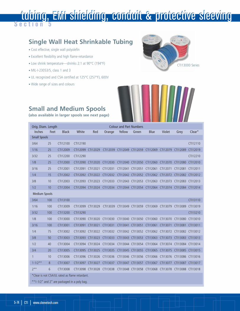
tubing, EMI shielding, conduit & protective sleevingtubing, EMI shielding, conduit & protective sleevingS e c t i o n 5
| CTI | www.cleevetech.com 5-74
Orig. Diam. Length Colour and Part NumbersInches Feet Black White Red Orange Yellow Green Blue Violet Grey Clear*
Single Wall Heat Shrinkable Tubing• Cost effective, single wall polyolefin
• Excellent flexibility and high flame-retardance
• Low shrink temperature—shrinks 2:1 at 90°C (194°F)
• MIL-I-23053/5, class 1 and 3
• UL recognized and CSA certified at 125°C (257°F), 600V
• Wide range of sizes and colours
Small and Medium Spools (also available in larger spools see next page)
CTI13000 Series
Small Spools
3/64 25 CTI12100 CTI12190 CTI12110
1/16 25 CTI12009 CTI12099 CTI12029 CTI12039 CTI12049 CTI12059 CTI12069 CTI12079 CTI12089 CTI12019
3/32 25 CTI12200 CTI12290 CTI12210
1/8 25 CTI12000 CTI12090 CTI12020 CTI12030 CTI12040 CTI12050 CTI12060 CTI12070 CTI12080 CTI12010
3/16 25 CTI12001 CTI12091 CTI12021 CTI12031 CTI12041 CTI12051 CTI12061 CTI12071 CTI12081 CTI12011
1/4 15 CTI12002 CTI12092 CTI12022 CTI12032 CTI12042 CTI12052 CTI12062 CTI12072 CTI12082 CTI12012
3/8 10 CTI12003 CTI12093 CTI12023 CTI12033 CTI12043 CTI12053 CTI12063 CTI12073 CTI12083 CTI12013
1/2 10 CTI12004 CTI12094 CTI12024 CTI12034 CTI12044 CTI12054 CTI12064 CTI12074 CTI12084 CTI12014
Medium Spools
3/64 100 CTI13100 CTI13110
1/16 100 CTI13009 CTI13099 CTI13029 CTI13039 CTI13049 CTI13059 CTI13069 CTI13079 CTI13089 CTI13019
3/32 100 CTI13200 CTI13290 CTI13210
1/8 100 CTI13000 CTI13090 CTI13020 CTI13030 CTI13040 CTI13050 CTI13060 CTI13070 CTI13080 CTI13010
3/16 100 CTI13001 CTI13091 CTI13021 CTI13031 CTI13041 CTI13051 CTI13061 CTI13071 CTI13081 CTI13011
1/4 75 CTI13002 CTI13092 CTI13022 CTI13032 CTI13042 CTI13052 CTI13062 CTI13072 CTI13082 CTI13012
3/8 50 CTI13003 CTI13093 CTI13023 CTI13033 CTI13043 CTI13053 CTI13063 CTI13073 CTI13083 CTI13013
1/2 40 CTI13004 CTI13094 CTI13024 CTI13034 CTI13044 CTI13054 CTI13064 CTI13074 CTI13084 CTI13014
3/4 20 CTI13005 CTI13095 CTI13025 CTI13035 CTI13045 CTI13055 CTI13065 CTI13075 CTI13085 CTI13015
1 10 CTI13006 CTI13096 CTI13026 CTI13036 CTI13046 CTI13056 CTI13066 CTI13076 CTI13086 CTI13016
1-1/2** 8 CTI13007 CTI13097 CTI13027 CTI13037 CTI13047 CTI13057 CTI13067 CTI13077 CTI13087 CTI13017
2** 6 CTI13008 CTI13098 CTI13028 CTI13038 CTI13048 CTI13058 CTI13068 CTI13078 CTI13088 CTI13018
*Clear is not CSA/UL rated as flame retardant.
**1-1/2” and 2” are packaged in a poly bag.

S e c t i o n 5
tubing, EMI shielding, conduit & protective sleeving | CTI | 5-75
Bulk ProgramNote: Some sizes and colours are available by special order only. Contact CTI Customer Service with your requirements.
4 ft. lengths in poly bags
Large Spools
CTI19000 Series
Orig. Diam. Pieces Colour and Part NumbersInches Per Bag Black White Red Yellow Green Blue Clear*
1/16 25 CTI91009 CTI91099 CTI91029 CTI91049 CTI91059 CTI91069 CTI91019
3/32 25 CTI91200 CTI91290 CTI91220 CTI91240 CTI91250 CTI91260 CTI91210
1/8 25 CTI91000 CTI91090 CTI91020 CTI91040 CTI91050 CTI91060 CTI91010
3/16 25 CTI91001 CTI91091 CTI91021 CTI91041 CTI91051 CTI91061 CTI91011
1/4 15 CTI91002 CTI91092 CTI91022 CTI91042 CTI91052 CTI91062 CTI91012
3/8 15 CTI91003 CTI91093 CTI91023 CTI91043 CTI91053 CTI91063 CTI91013
1/2 10 CTI91004 CTI91094 CTI91024 CTI91044 CTI91054 CTI91064 CTI91014
3/4 10 CTI91005 CTI91095 CTI91025 CTI91045 CTI91055 CTI91065 CTI91015
1 10 CTI91006 CTI91096 CTI91026 CTI91046 CTI91056 CTI91066 CTI91016
1-1/2 5 CTI91007 CTI91097 CTI91027 CTI91047 CTI91057 CTI91067 CTI91017
2 5 CTI91008 CTI91098 CTI91028 CTI91048 CTI91058 CTI91068 CTI91018
3 5 CTI91300 CTI91390 CTI91320 CTI91340 CTI91350 CTI91360 CTI91310
*Clear is not CSA/UL rated as flame retardant.
Orig. Diam. Length Colour and Part NumbersInches Feet Black White Red Orange Yellow Green Blue Violet Grey Clear*
3/64 1000 CTI19100 CTI19190 CTI19120 CTI19130 CTI19140 CTI19150 CTI19160 CTI19170 CTI19180 CTI19110
1/16 1000 CTI19009 CTI19099 CTI19029 CTI19039 CTI19049 CTI19059 CTI19069 CTI19079 CTI19089 CTI19019
3/32 500 CTI19200 CTI19290 CTI19220 CTI19230 CTI19240 CTI19250 CTI19260 CTI19270 CTI19280 CTI19210
1/8 500 CTI19000 CTI19090 CTI19020 CTI19030 CTI19040 CTI19050 CTI19060 CTI19070 CTI19080 CTI19010
3/16 500 CTI19001 CTI19091 CTI19021 CTI19031 CTI19041 CTI19051 CTI19061 CTI19071 CTI19081 CTI19011
1/4 250 CTI19002 CTI19092 CTI19022 CTI19032 CTI19042 CTI19052 CTI19062 CTI19072 CTI19082 CTI19012
3/8 200 CTI19003 CTI19093 CTI19023 CTI19033 CTI19043 CTI19053 CTI19063 CTI19073 CTI19083 CTI19013
1/2 150 CTI19004 CTI19094 CTI19024 CTI19034 CTI19044 CTI19054 CTI19064 CTI19074 CTI19084 CTI19014
3/4 100 CTI19105 CTI19195 CTI19125 CTI19135 CTI19145 CTI19155 CTI19165 CTI19175 CTI19185 CTI19115
3/4 250 CTI19005 CTI19095 CTI19025 CTI19035 CTI19045 CTI19055 CTI19065 CTI19075 CTI19085 CTI19015
1 100 CTI19106 CTI19196 CTI19126 CTI19136 CTI19146 CTI19156 CTI19166 CTI19176 CTI19186 CTI19116
1 250 CTI19006 CTI19096 CTI19026 CTI19036 CTI19046 CTI19056 CTI19066 CTI19076 CTI19086 CTI19016
1-1/2 125 CTI19007 CTI19097 CTI19027 CTI19037 CTI19047 CTI19057 CTI19067 CTI19077 CTI19087 CTI19017
2 125 CTI19008 CTI19098 CTI19028 CTI19038 CTI19048 CTI19058 CTI19068 CTI19078 CTI19088 CTI19018
3 100 CTI19300 CTI19390 CTI19320 CTI19330 CTI19340 CTI19350 CTI19360 CTI19370 CTI19380 CTI19310
4 100 CTI19400 CTI19490 CTI19420 CTI19430 CTI19440 CTI19450 CTI19460 CTI19470 CTI19480 CTI19410
*Clear is not CSA/UL rated as flame retardant.
Cutting ServiceCustom cutting is available. Select the part number from the “Large Spools” table.(Minimum order must be the equivalent of one spool). Contact customer service for details.

tubing, EMI shielding, conduit & protective sleevingtubing, EMI shielding, conduit & protective sleevingS e c t i o n 5
| CTI | www.cleevetech.com 5-76
Part # by Blister Card Polybag PolybagColour & Pack Size (3” lengths) (6” lengths) (4 ‘ lengths)Size Original Diam. # Pcs Black # Pcs Black Clear # Pcs Black Clear
Assorted (Sizes) 5 CTI14000 7 CTI15000 CTI15010 n/a n/a n/a
#1 0.225” 10 CTI14001 14 CTI15001 CTI15011 25 CTI54801 CTI54811
#2 0.293” 8 CTI14002 12 CTI15002 CTI15012 25 CTI54802 CTI54812
#3 0.427” 5 CTI14003 10 CTI15003 CTI15013 20 CTI54803 CTI54813
#4 0.700” 2 CTI14004 5 CTI15004 CTI15014 15 CTI54804 CTI54814
Clear tubing allows
for easy inspection
Dual Wall Heat Shrinkable Tubing• Semi-rigid, flame-retardant polyolefin jacket
• Inner layer of specially formulated adhesive
• High shrink ratio of 4:1
• Extended temperature range of -40°C to 130°C (-40°F to 266°F)
• Markings for size
• UL 224 600V, 125°C
Thermafix Plus™ is a semi-rigid, ‘dual wall’ tubing, designed to meet automotive industry
requirements for environmental sealing. As the tubing is heated, an inner wall of adhesive
melts and flows to form an effective barrier against automotive fluids and moisture. This
helps to protect the harness from the effects of corrosion and water wicking.
OEM Approved
Adhesive lined, seals and protects
Thermafix DWP™ (Flexible)• Flexible, flame-retardant polyolefin jacket
• Available from 1/8” to 1” original diameter
• High shrink ratio of 3:1
• Adhesive lining
• Meets UL 224 600V, 125°C and MIL-I-23053/4
Thermafix DWP™ is a flexible, ‘dual wall’ tubing, used for sealing
and protecting mechanical and electrical systems (including splices,
breakouts, and connector-to-cable transitions).
Original Poly bag (12” lengths) Poly bag (4 ‘ lengths)Diameter (in) Pcs Black Red Pcs Black Red
1/8 8 CTI31100 CTI31120 50 CTI31400 CTI31420
3/16 8 CTI31101 CTI31121 50 CTI31401 CTI31421
1/4 8 CTI31102 CTI31122 25 CTI31402 CTI31422
3/8 8 CTI31103 CTI31123 25 CTI31403 CTI31423
1/2 8 CTI31104 CTI31124 25 CTI31404 CTI31424
3/4 4 CTI31105 CTI31125 25 CTI31405 CTI31425
1 4 CTI31106 CTI31126 15 CTI31406 CTI31426
1-1/2 4 CTI31107 CTI31127 15 CTI31407 CTI31427
Thermafix DWP™ is now available in other colours by special order only (minimum quantities apply)

S e c t i o n 5
tubing, EMI shielding, conduit & protective sleeving | CTI | 5-77
Heavy Duty & Self-SealingHeat Shrinkable Tubing• Provides excellent strain relief and abrasion protection
• Shrink ratio as high as 3:1
• Meltable lining provides protection underwater and underground
(for without meltable lining, see Thermafix ST™ Non-Adhesive below)
• Rated for up to 600 volts, 90°C (194°F) continuous
• Meets UL Standard
Available in various lengths as follows:
Thermafix ST™ Non-Adhesive
Thermafix ST™in popular sizesfor automotiveapplications.General purpose sealant lining
provides an environmental seal and
will adhere to non-oily substances. The
tubing can be removed where re-entry
is necessary.
Diameter For Cable Range (8” pcs)* (12” pcs)* (4 ‘ pcs)*
(original)(final) (AWG/MCM) Pcs Part # Pcs Part # Pcs Part #
in. in. /bag Black Red /bag Black Red /bag Black Red
0.40 0.15 #14 - #10 4 CTI80604* CTI70604* 4 CTI81004* CTI71004* 10 CTI83004* CTI73004*
0.75 0.22 #8 - #1 4 CTI80807 CTI70807 4 CTI81207 CTI71207 10 CTI84807 CTI74807
1.10 0.38 #2 - #4/0 2 CTI80811 CTI70811 2 CTI81211 CTI71211 5 CTI84811 CTI74811
1.30 0.38 #2 - #4/0 2 CTI80813 2 CTI81213 5 CTI84813
1.50 0.50 #2/0 - 500 2 CTI80815 2 CTI81215 2 CTI84815
1.70 0.50 #2/0 - 500 2 CTI80817 2 CTI81217 2 CTI84817
2.00 0.75 #350 - 1000 2 CTI80820 2 CTI81220 2 CTI84820
3.00 1.25 #900 - 1500 2 CTI80830 2 CTI81320 2 CTI84830
4.00 1.75 #1500 - 2500 2 CTI80840 2 CTI81240 2 CTI84840
*Important: Diam. 0.40 is available in lengths of 6”, 10” or 30” (i.e. not 8”, 12” or 4’)
Diameter (in) Length (in) # of Pcs Colour Part #
0.75 48 10 Black CTI84807NA
1.1 48 5 Black CTI84811NA
1.5 48 2 Black CTI84815NA
Diameter (in) Length (in) # of Pcs Colour Part #
1.10 1.5 6 Black CTI15005
1.10 1.5 6 Red CTI15025
1.10 1.5 6 3 Black & 3 Red CTI15085
1.10 6.0 2 Black CTI15605
1.10 6.0 2 Red CTI15625
0.75 6.0 4 Black CTI80607
0.75 6.0 4 Red CTI70607

tubing, EMI shielding, conduit & protective sleevingtubing, EMI shielding, conduit & protective sleevingS e c t i o n 5
| CTI | www.cleevetech.com 5-78
Braided PET Sleeving• Bundling • Organization • Colour Coding• Chafe Proofing • Wire Harnessing
Electrical TapeHigh quality 7 mil thick PVC electrical tape is 18 mm
(3/4”) wide x 20 m (66’) long and is CSA approved.
Sold in sleeves of 6 in several colours.
Standard Colours0-Black
1-Clear
2-Red
3-Orange
4-Yellow
Custom ColoursB-Beige
P-Pink
2N-Neon Red
5-Green
6-Blue
7-Purple
8-Grey
9-white
4N-Neon Yellow
5N-Neon Green
6N-Neon Blue
Size Nominal Length Part Numbers
Diameter
Inches Inches Feet Black Clear Red Orange Yellow Green Blue Purple Grey White
Standard Colours
3/8 3/16 to 5/8 500 CTI50038-0 CTI50038-1 CTI50038-2 CTI50038-3 CTI50038-4 CTI50038-5 CTI50038-6 CTI50038-7 CTI50038-8 CTI50038-9
3/8 3/16 to 5/8 50 CTI55038-0 - - - - - - - CTI55038-8 -
1/2 1/4 to 3/4 500 CTI50012-0 CTI50012-1 CTI50012-2 CTI50012-3 CTI50012-4 CTI50012-5 CTI50012-6 CTI50012-7 CTI50012-8 CTI50012-9
1/2 1/4 to 3/4 50 CTI55012-0 - - - - - - - CTI55012-8 -
3/4 1/2 to 1-1/4 250 CTI50034-0 CTI50034-1 CTI50034-2 CTI50034-3 CTI50034-4 CTI50034-5 CTI50034-6 CTI50034-7 CTI50034-8 CTI50034-9
3/4 1/2 to 1-1/4 25 CTI52034-0 - - - - - - - CTI52034-8 -
1-1/4 3/4 to 1-3/4 250 CTI50125-0 CTI50125-1 CTI50125-2 CTI50125-3 CTI50125-4 CTI50125-5 CTI50125-6 CTI50125-7 CTI50125-8 CTI50125-9
1-1/4 3/4 to 1-3/4 25 CTI52125-0 - - - - - - - CTI52125-8 -
*Note: Some colours are not kept in stock and are available by special order and are subject to minimum order quantity.
PET is braided from a 10 mil
monofilament yarn of polyethyl-
ene terephthalate. It is especially
useful in passive applications
where flexibility, durability and
economy are important con-
siderations.
Part #
CTI33001 PVC Elect tape black 20 m 6pk
CTI33002 PVC Elect tape 3 black & 3 red 20 m 6pk
CTI33003 PVC Elect tape 3 black & 3 orange 20 m 6pk
CTI33004 PVC Elect tape 3 black & 3 yellow 20 m 6pk
CTI33005 PVC Elect tape 3 black & 3 green 20 m 6pk
CTI33006 PVC Elect tape 3 black & 3 blue 20 m 6pk
CTI33007 PVC Elect tape 3 black & 3 purple 20 m 6pk
CTI33008 PVC Elect tape 3 black & 3 white 20 m 6pk
CTI33009 PVC Elect tape 3 black & 3 grey 20 m 6pk
Tape AssortmentAn assortment of PVC tape in 5 different colours.
Each roll is 3.7 m (12’).
Part #
CTI73250 Elect Tape 5 x 3.7 m Colour Assortment
Self-Bonding Tape
Self-Bonding Tape bonds to itself to form a rubber
covering. By stretching the tape, its adhesive like
properties are activated. Has many uses around the
home and shop.
Weather Resistant TapeCold and weather resistant. This 8 mil thick tape is
18 mm (3/4”) wide x 20 m (66’) long and is CSA
approved. Sold in sleeves of 6.
Part #
CTI38901 Weather Resistant Tale 20 m
Part #
CTI69972 Self Bonding Tape

S e c t i o n 5
tubing, EMI shielding, conduit & protective sleeving | CTI | 5-79
Elastomeric Sleeving for Wire & CableNeoprene Rubber ‘Hellermann’ Sleeves
Hellermann brand neoprene rubber sleeves are ideally suited for identification and protection of wire terminations. Available in a wide
variety of colours, they can be installed quickly by stretching (up to 5x) using the 3-pronged applicator tools shown below. Known as
‘H-Series’ sleeves, these are very popular in the telecommunications and broadcasting industries where quick removal can be important.
• Temp. range of -65°C to 95°C
• Sizes (Diam) from 1.2 mm to 20 mm
• Available in all international resistor colour codes, as well as pink
Please contact customer service for other formulations available:
TH Series Neoprene for applications where thinner wall thickness is required
HT Series (Nitrile Rubber) for higher temperature environments (up to 120°C)
SLP Series (Silicone Rubber) for even higher temperatures (up to 180°C)
P Series (PVC) thin wall and colour-coded, wire identification markers.
‘H’ Series Standard Pack SizesPart # Nominal ID Nominal Wall Standard Pack Standard Lengths Available
(mm) (mm) Size 1/2” 3/4” 1” 1-1/4” 1-1/2” 2”
CTIH12 1.20 0.75 1000 • • • • •
CTIH15 1.50 0.75 1000 • • • • •
CTIH20 2.00 0.75 1000 • • • • •
CTIH25 2.50 0.75 1000 • • • • •
CTIH30 3.00 0.75 1000 • • • • •
CTIH40 4.00 1.00 1000 • • • • •
CTIH50 5.00 1.00 1000 • • • • •
CTIH75 7.50 1.25 100 • • • • •
CTIH100 10.0 1.50 100 • • • • •
CTIH150 15.0 1.70 100 • • • • •
CTIH200 20.0 2.00 100 • • • • •
AccessoriesPart #
CTID-Kit Tool body, 3 prongs, lubricant & sizer
CTISFT-3033 Replacement ‘SS’ prongs for above
CTISFT-3034 Replacement ‘S’ prongs for above
CTISFT-3035 Replacement ‘K’ prongs for above
CTISS Tool Tool for H12 to H20 x 3/4” long
CTIS Tool Tool for H25 to H40 x 3/4” long
CTIK Tool Tool for H50 to H100 x 1-1/4” long
CTIG Tool Tool for H150 to H200 x 2” long
CTIHD-SS Heavy duty ‘SS’ tool
CTIHD-S Heavy duty ‘S’ tool
Part #
CTIHD-K Heavy duty ‘K’ tool
CTIHD-G Heavy duty ‘G’ tool
CTILube-M Type ‘M’ lubricant 284 ml
To order please specify: Part # - Length - Colour Code eg. H20-3/4-2 (2.0 mm ID, 3/4” long, Red)
K-Tool Heavy Duty
S-Tool
D-Kit Complete with:
• Tool body
• 3 prongs
• Lubricant
• Sizer
Color Code0-Black1-Brown
2-Red3-Orange4-Yellow
5-Green6-Blue7-Violet
8-Grey9-WhiteP-Pink

tubing, EMI shielding, conduit & protective sleevingtubing, EMI shielding, conduit & protective sleevingS e c t i o n 5
| CTI | www.cleevetech.com 5-80
Looms and TubingPolyethylene Slit LoomSlit seam construction allows for easy wire insertion and repair, yet
retains wire even when bent or twisted. Maximum temperature
93˚C (200˚F). Ideal for protecting wire from heat, sunlight, water,
snow, ice, salt, friction and vibration wear, fraying and puncture.
UV stabilized black.
Diam. Length Colours and Part #’s(in) (ft) Black White Red Yellow Blue Teal Purple
Convenience Packs
1/4 12 CTI47114
1/4 50 CTI47014 CTI41014 CTI42014 CTI44014 CTI46014 CTI45014 CTI43014
3/8 10 CTI47138
3/8 50 CTI47038 CTI41038 CTI42038 CTI44038 CTI46038 CTI45038 CTI43038
1/2 8 CTI47112
1/2 50 CTI47012 CTI41012 CTI42012 CTI44012 CTI46012 CTI45012 CTI43012
5/8 50 CTI47058
3/4 50 CTI47034 CTI41034 CTI42034 CTI44034 CTI46034 CTI45034 CTI43034
1 50 CTI47010
1-1/4 50 CTI47125
Bulk Packs
1/4 3200 CTI47914 CTI41914 CTI42914 CTI44914 CTI46914 CTI45914 CTI43914
3/8 1900 CTI47938 CTI41938 CTI42938 CTI44938 CTI46938 CTI45938 CTI43938
1/2 1100 CTI47912 CTI41912 CTI42912 CTI44912 CTI46912 CTI45912 CTI43912
5/8 800 CTI47958
3/4 550 CTI47934 CTI41934 CTI42934 CTI44934 CTI46934 CTI45934 CTI43934
1 300 CTI47910
1-1/4 250 CTI47925
1-1/2 150 CTI47915
2 100 CTI47920
Note: Some sizes and colours are avail-
able by special order only. Contact cus-
tomer service to determine availability.
Slit Loom Installation Tool
Diameter Length Part #
(in) (ft) Black
Convenience Packs
1/4 50 CTI48014
3/8 50 CTI48038
1/2 50 CTI48012
5/8 50 CTI48058
3/4 50 CTI48034
1 50 CTI48010
Diameter Length Part #
(in) (ft) Black
Bulk Packs
1/4 3200 CTI48914
3/8 1900 CTI48938
1/2 1100 CTI48912
5/8 800 CTI48958
3/4 550 CTI48934
1 300 CTI48910
1-1/4 250 CTI48925
1-1/2 150 CTI48915
Part #
CTI50241 For smaller diameters (1/4”, 3/8” & 1/2”)
CTI50242 For larger diameters (1/2”, 5/8” & 1”)
High TemperatureNylon Slit LoomSuitable for engine compartments this nylon slit loom,
identified by a grey stripe, has a temp-
erature rating of 149˚C (300˚F)

S e c t i o n 5
tubing, EMI shielding, conduit & protective sleeving | CTI | 5-81
Plastic LoomProvides a neat, professional appearance.
Flexible plastic facilitates easy wire feeding.
Maximum temperature rating 90˚C (194˚F).
Fiber LoomDurable non-metallic loom withstands abrasion,
provides excellent protection against electrical
interference and short circuits. Saturated with an
asphalt compound to provide moisture protec-
tion. Maximum temperature rating 135˚C (275˚F).
Braided Nylon SleevingA protective wire covering, designed to be used where a combi-
nation of abrasion resistance and high flexibility must be obtained
at a moderately high temperature. Ideal for automotive wire
harnesses and in commercial applications such as robotics and
assembly equipment where continuous flexing is required.
Operating Temp. Range: 55°C (-67°F) to +170°C (338°F)
Shrinkage: 7% max @ 100°C
Abrasion resistance: 1,300,000 cycles
Note: where chemical, electrical and temperature resistance are
not required, see our general purpose PET monofilament braided
sleeving on next page.
Spiral WrapFor protection of wire bundles from 0.063” to 7”.
Polyethylene (UL flammability-not rated).
Vinyl Coated Braided Fiberglass SleevingA new alternative to the traditional, asphalt-saturated Fiber Loom.
This vinyl-coated, heavy duty insulating sleeving is especially suit-
ed where a combination of electrical characteristics, chemical
resistance, thermal properties and cut-through resistance is
required. Ideal as a protective covering on leadwires, connectors
in motors, transformers and similar apparatus.
Operating Temperature Range:-20°C (-4°F) to +130°C (266°F)
Dielectric Strength: 4000 volt min. avg. (MIL-I-21557)
Other Ratings: VW-1 flame retardant, UL #E80713
Bench Mount Hot Knife110 volt ACThis tool enables the operator to draw the sleeving down across the knife blade - under tension. Both hands are thenfree to manipulate the sleeving and to seal and flare the ends.
• Tool should be used in well
ventilated areas.
• Warms up in less than 30 seconds.
• Cuts through a 1” nylon
line in ten seconds.
Part # ID Size Length
CTI69841 1/4” (6.40 mm) 100’ coil (30.5 m)
CTI69843 3/8” (9.50 mm) 100’ coil (30.5 m)
CTI69845 1/2” (12.70 mm) 100’ coil (30.5 m)
CTI69847 5/8” (15.90 mm) 100’ coil (30.5 m)
Part # ID Size Length
CTI69801 1/4” (6.4 mm) 100’ coil (30.5 m)
CTI69803 3/8” (9.5 mm) 100’ coil (30.5 m)
CTI69805 1/2” (12.7 mm) 100’ coil (30.5 m)
CTI69807 5/8” (15.9 mm) 100’ coil (30.5 m)
CTI69833 3/4” (19.1 mm) 25’ coil (7.6 m)
CTI69859 1” (25.4 mm) 25’ coil (7.6 m)
Part # - Spool Size (ft)
Diameter 50 100 250 500
3/8 CTI69200 CTI69400
1/2 CTI69201 CTI69401
3/4 CTI69202 CTI69402
1 CTI69203 CTI69403
Part # - Spool Size (ft)
Diameter 50 100 250
1/3 CTI69000 CTI69100
1/2 CTI69001 CTI69101
3/4 CTI69002 CTI69102
1 CTI69003 CTI69103
Diameter Bundle Range (in) Part #(in) min max Natural Black
1/8 0.063 0.50 CTI49018 CTI59018
1/4 0.188 2.00 CTI49014 CTI59014
3/8 0.313 3.00 CTI49038 CTI59038
1/2 0.375 4.00 CTI49012 CTI59012
3/4 0.750 5.00 CTI49034 CTI59034
1 1.000 7.00 CTI49010 CTI59010
Part #
CTIHKBM Bench Mount Hot Knife

tubing, EMI shielding, conduit & protective sleevingtubing, EMI shielding, conduit & protective sleevingS e c t i o n 5
| CTI | www.cleevetech.com 5-82
Thermafix DCTM Flexible, Flame-Retardant, Dual Colour Polyolefin TubingUsed to identify ‘ground’ on wires and in cables, and to jacket and insulate light duty harnesses.
• CSA/UL rated for 600V, 125ºC
• Shrink ratio of 2:1
• Dual colours (yellow/green) for instant identification
• Flame retardant
• Flexible to conform to irregular shapes
• Excellent physical, chemical and electrical properties that meet
industry standards for highly reliable, general purpose tubing
Thermafix AdhesiveTM Hot Melt Glue in Film FormNot heat shrink tubing, but ideal for use with non-adhesive lined heat shrink
tubings in low temperature applications. Simply place underneath tubing,
prior to heating, and material will melt and flow similar to pre-installed
adhesive linings. Use with single wall tubing to get dual wall results.
Thermafix Kynar® High TemperatureHeat Shrinkable Tubing• Semi-rigid, high performance, flame resistant,
polyvinylidene fluoride
• Ideal for high temperature applications to 175°C (347°F)
• Superior chemical and solvent properties
• Shrink ratio of 2:1
• Meets CSA Std 198 OFT 600V, 125°C ; UL224 VW-1; and,
MIL-I-23053/8
• Standard colour is clear
Other Specialty Heat Shrink Products and Tubing:Thermafix 3XTM Low Shrink Temperature/High Shrink Ratio Heat Shrinkable Tubing• Very flexible, highly flame retardant,
low-shrink temperature polyolefin
• Shrink ratio of 3:1
• UL VW-1and CSA OFT
• Standard colours are black and white
(for custom colours please contact us)
Original Medium Spools Bulk Spools
Diameter Part # Part #
(in) (ft) Black White (ft) Black White
1/4 75 CTI23002 CTI23092 250 CTI23902 CTI23992
3/8 50 CTI23003 CTI23093 200 CTI23903 CTI23993
1/2 40 CTI23004 CTI23094 150 CTI23904 CTI23994
3/4 20 CTI23005 CTI23095 250 CTI23905 CTI23995
1 10 CTI23006 CTI23096 250 CTI23906 CTI23996
1-1/2* 8 CTI23007 CTI23097 98 CTI23907 CTI23997
*1-1/2” x 8’ is poly bagged
Original Diameter Medium Spools Bulk Spools
(in) (ft) Yellow Green (ft) Yellow Green
1/8 100 CTI13451 450 CTI19451
1/4 75 CTI13452 225 CTI19452
3/8 50 CTI13453 150 CTI19453
1/2 40 CTI13454 150 CTI19454
3/4 20 CTI13455 150 CTI19455
1 10 CTI13456 75 CTI19456
Original Diameter Standard 4 ft Lengths
(in) Pcs Part # Pcs Part #
1/16 50 CTI29009 10 CTI29019
3/32 50 CTI29200 10 CTI29210
1/8 50 CTI29000 10 CTI29010
3/16 50 CTI29001 10 CTI29011
1/4 25 CTI29002 5 CTI29012
3/8 25 CTI29003 5 CTI29013
1/2 25 CTI29004 5 CTI29014
3/4 25 CTI29005 5 CTI29015
Part # Width Length
CTI10175 1” 5’ strip
CTI10170 1” 50’ roll

S e c t i o n 5
tubing, EMI shielding, conduit & protective sleeving | CTI | 5-83
Custom Cut & Printed Thermafix® Whether for identification or function, custom cut and printed Thermafix® is an effective and economical solution.
Flat
Height
is 1.25”
Side view
-------------------- Cross-sectional view --------------------
Example for 3/4” tubing:A B C D
(Original diameter) (Full recovery 2:1) (Full recovery 3:1)
3/4” 3/8”
Design
Determine elements required such as:
• Text/description
• Logos (e-mail or supply disk with graphics file in .jpeg or .tiff format)
• Any sequential numbering required (e.g. serial numbers)
• Submit a sample drawing using ‘flat height’ sizing
• Please allow an adequate margin on all sides of image
Other Considerations
• Available cut, or not cut (i.e. rolled)
• Available in single or dual wall (black only)
• Heat Shrinkable adhesive tape available for extra durability and grip
Colours Available
Colours of tubing available:
2:1 Shrink Ratio
3:1 Shrink Ratio
Colours of print available:
Sizing
• Tubing is available in 2:1 or 3:1 shrink ratios.
• Pieces are available in any length (priced perinch). Most common lengths are 1 to 2” ( 25 to50 mm).
• Printing can be on one or both sides of the flat-tened tube. Flat tube ‘height’ in relation toround diameter is shown as per the followingexample and in the table below:
1/4”
A B C D
(Flat height) (Original diameter) (Full recovery 2:1) (Full recovery 3:1)9/32 1/8 1/16 N/A
12/32 3/16 3/32 N/A
7/16 1/4 1/8 1/12
9/16 3/8 3/16 1/8
7/8 1/2 1/4 1/6
1-1/4 3/4 3/8 1/4
1-11/16 1 1/2 1/3
2-3/8 1-1/2 3/4 1/2
Grey Violet Orange
White Black Red Yellow Blue Green
White Black Red
Black Silver White Blue Red Green Gold

ID MARKER
ID MARKERCLEEVE CABLE
1
4
6 7
5
3
2
8
HARNESS NUMBER
LENGTH A
1.0 TYP.3
NOTES, UNLESS OTHERWISE SPECIFIEDIDENTIFICATION MARKER TO BE USED AT EACH CONNECTOR END1.
SHIELDS CONNECTED TO PIN "E" ON BOTH CONNECTORS2.
SPECIFICATION CONTROL DRAWING
ITEM 7 TO BE APPLIED OVER MARKERS
3
-1
REVISIONS
ZONE REV. DESCRIPTION DATE APPROVED
- PRELIMINARY RELEASE AUG 24 2006 PC
1 ADD BAND MARKERS, TITLE CHANGE, BOM MOD OCT 4 06 PC
2 ADD PART MARKER, EDIT BOM OCT 17 06 CS
ITEM NO. PART NUMBER DESCRIPTION QTY.1 FAE-3475-14-5SN CONNECTOR, PLUG 12 SB-CABO-1406-UN40 BACKSHELL 23 FMP-K121-25WA MOULDED PART 24 FAE-3474-14-5PN CONNECTOR, RECEPTICLE 1
5 FRCL-AA001BA CABLEA/R
SEE LENGTH "A"ADD10%
6 M053-5-3/4-9 (WHITE) HEAT SHRINK TUBING (50mm) 3
7 M053-5-3/4-C (CLEAR) HEAT SHRINK TUBING (60mm) 3
8 M053-5-1-4 (YELLOW) HEAT SHRINK TUBING (30mm) 3
CONFIG LENGTH A-1 9FT
THE INFORMATION CONTAINED IN THISDRAWING IS THE SOLE PROPERTY OFCLEEVE TECHNOLOGY INCORPORATED ANY REPRODUCTION IN PART OR AS AWHOLE WITHOUT THE WRITTEN PERMISSIONOF CLEEVE TECHNOLOGY INCORPORATEDIS PROHIBITED.
PROPRIETARY AND CONFIDENTIAL
NEXT ASSY USED ON
APPLICATION
DIMENSIONS ARE IN INCHESTOLERANCES:FRACTIONALANGULAR: MACH BEND TWO PLACE DECIMAL THREE PLACE DECIMAL
INTERPRET GEOMETRICTOLERANCING PER: NA
FINISH
DRAWN
CHECKED
ENG APPR.
MFG APPR.
Q.A.
COMMENTS:
DATENAME CLEEVE TECHNOLOGY INCORPORATED
TITLE:
SIZE
BDWG. NO. REV
SCALE : NA
UNLESS OTHERWISE SPECIFIED:
2
CS AUG 24 06
CLEEVE HARNESSEXAMPLE 3
SHEET 1 OF 2
EXAMPLE 2DO NOT SCALE DRAWING CAGE: 3AN64
MATERIAL
kits, assemblies and feedthroughskits, assemblies and feedthroughsS e c t i o n 6
| CTI | www.cleevetech.com 6-84
CTI Value Added Solutions and CapabilitiesCTI can provide products in component form such as kits, sub assemblies or as finished and tested
assemblies. CTI can support existing designs, from ‘build to print’ to suggestions of product improvements
and cost saving opportunities through to new designs supported with samples, drawings and test data.
Mechanical Engineering, Design and Manufacturing Capabilities:
• Conceptual design providing 3D models and 2D drawings to current industrial/aerospace standards
• Fabrication services for machined and sheet metal components and assemblies, complex and standard
- Mechanical piece parts/assemblies, enclosures, chassis and test boxes
- Production/manufacturing assembly tooling
- Tooling/jigs/fixtures and mechanical test equipment
• Prototype and production manufacturing
• Mechanical packaging
• Mature product design improvement and feasibility studies
- Cost effective design analysis incorporating design modifications to avail more economic
manufacturing utilizing current processes and procedures to reduce cost and lead times
• Build to print prototype, pre and full production manufacturing/assembly
• Concurrent engineering and advanced manufacturing
Complementing these capabilities, CTI can provide turn key support to the design, manufacture, finishing,
assembly and delivery of our products.
14' - .0+3.0 INCHES INCHES1.0+
.0-2'
6' - .0+2.0 INCHES
THE INFORMATION CONTAINED IN THISDRAWING IS THE SOLE PROPERTY OFCLEEVE TECHNOLOGY INCORPORATED ANY REPRODUCTION IN PART OR AS AWHOLE WITHOUT THE WRITTEN PERMISSIONOF CLEEVE TECHNOLOGY INCORPORATEDIS PROHIBITED.
PROPRIETARY AND CONFIDENTIAL
NEXT ASSY USED ON
APPLICATION
DIMENSIONS ARE IN INCHESTOLERANCES:FRACTIONALANGULAR: MACH BEND TWO PLACE DECIMAL .005THREE PLACE DECIMAL
INTERPRET GEOMETRICTOLERANCING PER: NA
MATERIAL
FINISH
SEE DETAIL
NA
DRAWN
CHECKED
ENG APPR.
MFG APPR.
Q.A.
COMMENTS:
DATENAMECLEEVE TECHNOLOGY INCORPORATED
TITLE:
SIZE
BDWG. NO. REV
SCALE: NA
UNLESS OTHERWISE SPECIFIED:
2
CS SEP 18 06
EXAMPLE 1 CLEEVEHARNESS
SHEET 1 OF 2
EXAMPLE 1DO NOT SCALE DRAWING CAGE: 3AN64
SPECIFICATION CONTROL DRAWING
3 ITEM 9 TO BE APPLIED OVER MARKERS
IDENTIFICATION MARKER TO BE USED AT EACH CONNECTOR END1.
SHIELDS CONNECTED TO PIN "E" ON ALL CONNECTORS2.
NOTES, UNLESS OTHERWISE SPECIFIED
3
REVISIONS
ZONE REV. DESCRIPTION DATE APPROVED
- PRELIMINARY RELEASE OCT 2 06 PC
1 ADD BANDMARKER, TITLE CHANGE, BOM MODADD SCHEMATIC OCT 5 06 PC
2 MODIFY LENGTHS, PART NUMBERS, CABLE ROUTING OCT 17 06 CS
ITEMNO. PART NUMBER DESCRIPTION QTY.
1 FAE-24-WC35PN CONNECTOR, RECEPTICLE 12 SB-BABO-1308-UN40 BACKSHELL 13 FMP-K132-25WA MOULDED PART 14 FRCL-AA004AA CABLE 33 FT5 FAE-3475-10-7SF CONNECTOR, PLUG 46 SB-CABO-1006-UN40 BACKSHELL 47 FMP-K121-25WA MOULDED PART 48 M053-5-3/4-9 (WHITE) HEAT SHRINK TUBING (50mm) 5
9 M053-5-3/4-C (CLEAR) HEAT SHRINK TUBING (60MM) 5
10 M053-5-1-2 (RED) HEAT SHRINK TUBING (30mm) 5
1
2
3
7
6
5
10
8
4
ID MARKER
ID MARKERID MARKER
ID MARKER
9
ID MARKER
2.0 INCHES
INCHES2.0+.0-4'
5' 6" - .0+
1.0 TYP
2 (RED)

S e c t i o n 6
kits, assemblies and feedthroughs | CTI | 6-85
FMP207W213 to 264 2 Part Feedthrough
Materials available:
• EL Fluid resistant modified elastomer
• ZH Low fire hazard material
• PL Semi-rigid modified polyolefin
FMP207W213 10
FMP207W223 18
FMP207W234 28
FMP207W245 42
FMP207W256 64
FMP207W264 38
Coatings Material
EL
ZH
PL
Modifications Code
Two sided nut -01
Dimensions apply to all materials unless otherwise indicated.
Expanded as supplied (min) Recovered after heating (max)
J H J K M P R S T U
12 4 23 20 62 49 13 32 10
20 7 33 30 72 59 16 42 10
31 12 46 42 87 74 18 58 10
45 18 59 56 102 89 18 71 10
68 30 84 80 122 109 18 97 10
40 15 54 50 95 82 18 67 10
Available Coatings
WA High performance hot melt adhesive
WA High performance hot melt adhesive
WA High performance hot melt adhesive
Table of dimensions (mm)

kits, assemblies and feedthroughskits, assemblies and feedthroughsS e c t i o n 6
| CTI | www.cleevetech.com 6-86
Adaptor Boot AssembliesCTI’s FRKA are one part or many part assemblies for screened and unscreened cables. Constructed from CTI heat shrinkable Molded
parts and connector adaptors, the assembly consists of parts already well proven in harsh military environments. Installation is simply
achieved by coupling the adaptor to the connector and shrinking the rear of the Molded part onto the cable with a hot air gun. The
Molded part has a hot melt adhesive pre-installed to provide a bond between the cable jacket and the Molded part. When used in con-
junction with screened cables, the assembly provides electrical continuity between the cable screen and the connector.
Assemblies for most
connector interfaces
Straight assemblies 45° assemblies 90° assemblies
FAE 347 connectors or connector Code CConnector CTI Cable OD CTI Cable OD CTI Cable ODShell Size Part # Range (mm) Part # Range (mm) Part # Range (mm)
EL fluid resistant elastomer 08 FRKA0520 5.0-9.0 FRKA0560 5.0-8.0 N/A N/A10 FRKA0521 6.0-12.0 FRKA0561 6.0-10.0 FRKA1051 6.0-13.012 FRKA0522 7.2-16.0 FRKA0562 7.2-12.0 FRKA1052 7.2-16.014 FRKA0523 7.2-16.0 FRKA0563 7.2-12.0 FRKA1053 7.2-16.016 FRKA0524 8.5-20.0 FRKA0564 8.5-18.0 FRKA1054 8.5-20.018 FRKA0525 8.5-20.0 FRKA0565 8.5-18.0 FRKA1055 8.5-20.020 FRKA0526 10.0-24.0 FRKA0566 10.0-22.0 FRKA1056 10.0-24.022 FRKA0527 10.0-24.0 FRKA0567 10.0-22.0 FRKA1057 10.0-24.024 FRKA0528 15.8-34.0 FRKA0568 15.8-30.0 FRKA1058 15.8-34.0
ZH Low fire hazard material 08 FRKA0465 5.0-8.0 FRKA0603 5.0-8.0 N/A N/A10 FRKA0466 6.0-10.0 FRKA0604 6.0-10.0 FRKA1251 6.0-10.012 FRKA0467 7.2-12.0 FRKA0605 7.2-12.0 FRKA1252 7.2-12.014 FRKA0468 7.2-12.0 FRKA0606 7.2-12.0 FRKA1253 7.2-12.016 FRKA0469 8.5-18.0 FRKA0607 8.5-18.0 FRKA1254 8.5-18.018 FRKA0470 8.5-18.0 FRKA0608 8.5-18.0 FRKA1255 8.5-18.020 FRKA0471 10.0-22.0 FRKA0609 10.0-22.0 FRKA1256 10.0-22.022 FRKA0472 10.0-22.0 FRKA0610 10.0-22.0 FRKA1257 10.0-22.024 FRKA0473 15.8-30.0 FRKA0611 15.8-30.0 FRKA1258 15.8-30.0
FRKA ExampleAssemblies

S e c t i o n 6
kits, assemblies and feedthroughs | CTI | 6-87
Straight assemblies 45° assemblies 90° assemblies
FAE 26 connectors or connector code BConnector CTI Cable OD CTI Cable OD CTI Cable ODShell Size Part # Range (mm) Part # Range (mm) Part # Range (mm)
EL fluid resistant elastomer 08 FRKA0840 5.0-9.0 FRKA0970 5.0-8.0 N/A N/A10 FRKA0841 6.0-12.0 FRKA0971 6.0-10.0 FRKA0851 6.0-13.012 FRKA0842 7.2-16.0 FRKA0972 7.2-12.0 FRKA0852 7.2-16.014 FRKA0843 7.2-16.0 FRKA0973 7.2-12.0 FRKA0853 7.2-16.0
ZH low fire hazard material 08 FRKA0612 5.0-8.0 FRKA0780 5.0-8.0 N/A N/A10 FRKA0613 6.0-10.0 FRKA0781 6.0-10.0 FRKA1241 6.0-10.012 FRKA0614 7.2-12.0 FRKA0782 7.2-12.0 FRKA1242 7.2-12.014 FRKA0615 7.2-12.0 FRKA0783 7.2-12.0 FRKA1243 7.2-12.016 FRKA0616 8.5-18.0 FRKA0784 8.5-18.0 FRKA1244 8.5-18.0
M5015 connectors or connector code MConnector CTI Cable OD CTI Cable OD CTI Cable ODShell Size Part # Range (mm) Part # Range (mm) Part # Range (mm)
EL fluid resistant elastomer 08 FRKA0530 5.0-9.0 FRKA0540 5.0-8.0 N/A N/A10 FRKA0531 6.0-12.0 FRKA0541 6.0-10.0 FRKA1261 6.0-13.012 FRKA0532 7.2-16.0 FRKA0542 7.2-12.0 FRKA1262 7.2-16.014 FRKA0533 7.2-16.0 FRKA0543 7.2-12.0 FRKA1263 7.2-16.0
ZH low fire hazard material 08 FRKA0444 5.0-8.0 FRKA0580 5.0-8.0 N/A N/A10 FRKA0445 6.0-10.0 FRKA0581 6.0-10.0 FRKA1021 6.0-10.012 FRKA0446 7.2-12.0 FRKA0582 7.2-12.0 FRKA1022 7.2-12.014 FRKA0447 7.2-12.0 FRKA0583 7.2-12.0 FRKA1023 7.2-12.016 FRKA0448 8.5-18.0 FRKA0584 8.5-18.0 FRKA1024 8.5-18.018 FRKA0449 10.0-22.0 FRKA0585 10.0-22.0 FRKA1025 10.0-22.020 FRKA0450 10.0-22.0 FRKA0586 10.0-22.0 FRKA1026 10.0-22.022 FRKA0451 10.0-22.0 FRKA0587 10.0-22.0 FRKA1027 10.0-22.024 FRKA0452 15.8-30.0 FRKA0588 15.8-30.0 FRKA1028 15.8-30.0
D38999 Series I and II connectors or connector code AConnector CTI Cable OD CTI Cable OD CTI Cable ODShell Size Part # Range (mm) Part # Range (mm) Part # Range (mm)
EL fluid resistant elastomer 08 FRKA0500 5.0-9.0 FRKA0510 5.0-8.0 N/A N/A10 FRKA0501 6.0-12.0 FRKA0511 6.0-10.0 FRKA0831 6.0-13.012 FRKA0502 7.2-16.0 FRKA0512 7.2-12.0 FRKA0832 7.2-16.014 FRKA0503 7.2-16.0 FRKA0513 7.2-12.0 FRKA0833 7.2-16.0
ZH low fire hazard material 08 FRKA0640 5.0-8.0 FRKA0630 5.0-8.0 N/A N/A10 FRKA0641 6.0-10.0 FRKA0631 6.0-10.0 FRKA0721 6.0-10.012 FRKA0642 7.2-12.0 FRKA0632 7.2-12.0 FRKA0722 7.2-12.014 FRKA0643 7.2-12.0 FRKA0633 7.2-12.0 FRKA0723 7.2-12.016 FRKA0644 8.5-18.0 FRKA0634 8.5-18.0 FRKA0724 8.5-18.0

kits, assemblies and feedthroughskits, assemblies and feedthroughsS e c t i o n 6
| CTI | www.cleevetech.com 6-88
Feedthrough Boot AssembliesCTI’s Cable Feedthrough System (FRFS) is available as a one-piece part or as a kit of parts providing environmental sealing and screen
continuity to a bulkhead as a cable passes through. The assembly consists of a specifically designed locknut and `O' ring seal, onto the
rear of which is pre-installed heat shrinkable Molded parts. Installation is achieved by tightening the locknut on the rear of the
bulkhead which compresses the 'O' ring and ensures a small knife edge provides electrical contact between the assembly and the
bulkhead. When heat is applied to the Molded part, in the form of hot air, a seal to the cable is formed with hot melt adhesive. When
used in conjunction with screened cables the assembly contains a conductive adhesive which provides electrical continuity between the
screen and the bulkhead via an integral shield inside the Molded parts.
- Screened or unscreened cables;
- One-piece part, or kit of parts;
- One part covers wide cable range;
- Lightweight;
- Single or double sided assembly.
FRFS - Feedthrough
Adhesive SystemWA = Pre-coated
Molded part typeA = Straight unscreened D = 45° screenedB = 90° unscreened E = 90° screenedC = Straight screened
Molded part material EL semi-rigid elastomerZH zero halogen PL Semi-rigid modified polyolefin
Thread length 20mm standard(±5mm increments - available on request)
Assembly modification code0 = Standard assembly1 = Double sided assembly (only straight unscreened
boot available on double nut)3 = LocknutFeedthrough material/finish19B Aluminum alloy plated cadmium olive drab over electroless nickel19C Aluminum alloy plated electroless nickel62C Stainless steel plated electroless nickel
Feedthrough size
PartNumberingSystem
FRFS -12 - 62C - 0 - 20 - ZH - A - WA

S e c t i o n 6
kits, assemblies and feedthroughs | CTI | 6-89
Table of dimensions (mm)Feedthrough ‘J’ Diameter ‘M’ Thread ‘A’ Diameter A/F A/F P HoleSize Unscreened Screened Max Body Nut ±10% Size
Ja Jb Ja Jb Unscreened (H7)FRFS-12 11 5.6 7.5 5.0 M12 x 1.5 7.50 24 17 31 13.0FRFS-16 15 5.9 9.5 6.0 M16 x 1.5 10.20 29 22 48 17.0FRFS-20 19 7.1 11.5 7.2 M20 x 1.5 14.20 34 27 52 21.0FRFS-24 23 8.4 17.5 8.5 M24 x 1.5 19.20 38 30 65 25.0FRFS-30 29 9.9 21.5 10.0 M30 x 1.5 24.20 48 36 64 31.0FRFS-36 35 15.7 29.5 15.8 M36 x 1.5 30.20 52 41 95 37.0FRFS-48 45 16.8 N/A N/A M48 x 1.5 40.20 67 55 135 50.0
Ja = supplied dimension. Jb = dimension after free recovery

cable ties & cable management systemscable ties & cable management systemsS e c t i o n 7
| CTI | www.cleevetech.com 7-90
Labour Saving Wire IdentificationCTI’s wire identification systems bring the timesaving advantages of the computer and the
ruggedness of CTI’s tubing to the labour intensive world of electrical harness building.
Lists of wire labels can be easily created and edited on a computer, then printed out using
standard printing equipment. The labels meet commercial aerospace standards for mark perma-
nence. Their ladder-style configuration allows the marker sleeves to be printed on both sides.
Products include heat shrinkable marker sleeves in thin-wall and high-temperature versions,
tie-on cable markers and adhesive-backed wraparound markers for large cables or open wire
bundles, and adhesive-backed panel markers.
Terminations that Install Easily and ReliablyCTI’s large family of wire and cable interconnection devices provides high-performance
terminations that can be installed easily and reliably. In addition to electrical connections, these
products offer protection against corrosion, mechanical abuse, and the effects of electromag-
netic interference in sensitive equipment and unpressurized exposed areas.
The smallest, lightest, sealed crimp splices available, MiniSeal crimp splices preserve the quali-
ty of electrical connections.
CTI’s high-temperature shielded cable splices provide tough, low profile, fully shielded termina-
tions that can withstand the very high operating temperatures normally found in engine and
engine strut areas. When used in place of connectors, the splices maintain shielding while
saving weight and space. The splices install quickly and efficiently, and can be inspected
immediately. Splice components are available in convenient kits.
SolderSplice shield terminators can be installed quickly, yet pass the most stringent quality
assurance tests. When a device’s thermal ring melts and disappears, it gives positive indication
of a completely soldered joint. And the heat shrinkable tubing and meltable inserts provide
one-step strain-relief and encapsulation.
When repairing or connecting shielded cable, SolderSplice splices provide shielding equal to or
better than the original cable. Repeatable terminations ensure reliability and high performance.

S e c t i o n 7
cable ties and cable management systems | CTI | 7-91
Nylon Cable Ties Material SpecificationsMaterial Standard Colours Continuous Operating Temp. UL Flame Rating UV Resistance Agency Approvals
Max MinNylon 6/6 - Natural 185˚F -40˚F 94V-2 Poor MIL-M-20693A
General Purpose White 85˚C -40˚C ASTM-D 4066PA111Nylon 6/6 - Black 185˚F -40˚F 94V-2 Very good UL E64139(N)
UV Stabilized 85˚C -40˚C
Terminations Individual screens of primary wires that are to be terminated to a connector pin can be terminated with a SolderSplice termination
device. The most commonly used SolderSplice devices are detailed both with and without a primary wire lead.
The overall cable screen can be terminated by one of three termination methods: braided backshells, Tinel-lock or EMI bands.
CTI SolderSplice devices are used to terminate screened wires within FRCL or hand built cable. The device consists of a heat shrinkable
thermoplastic sleeve containing a precisely engineered preform of fluxed solder and thermoplastic inserts in each end. When placed over
a cable shield and heated, the solder melts and flows, connecting the ground lead to the cable shield. As the outer sleeve shrinks the
thermoplastic inserts melt and provide an environmentally sealed termination. SolderSplice devices are available with ground leads pre-
installed to make installation even easier.
Listed below are the most commonly used SolderSplice devices for use with wire rated up to 150°C.
For other applications consult CTI at [email protected]
SolderSplice devices
SolderSplice devices with ground lead
Cable Dimensions:
D max d min Part #
1.9 1.1 FRSS144-25
2.7 1.6 FRSS100-00
4.5 2.4 FRSS101-00
6.0 3.0 FRSS107-00
6.8 3.7 FRSS103-00
11.0 6.0 FRSS104-00
13.3 8.9 FRSS105-00
Cable Dimensions: Ground Lead Gauge (AWG)
D max d min Part #
2.7 1.6 FRSS100-34 FRSS900-01
4.3 2.4 FRSS101-34 FRSS900-02
6.8 3.7 FRSS103-34 FRSS900-03
Can be supplied with 6 inch length of M044 wire
with addition of suffix.
Example: FRSS-100-20-5
Colour
Wire AWG

cable ties & cable management systemscable ties & cable management systemsS e c t i o n 7
| CTI | www.cleevetech.com 7-92
StandardApproximate Approximate Max Bundle Tensile Colour Pcs/pack - Part # Length (in) Width (in) Diameter (in) Strength (lbs) 25 100 500 1000
4.00 0.10 5/8 18 Natural CTI17501 CTI17001 CTI179014.00 0.10 5/8 18 Black CTI17502 CTI17002 CTI179028.00 0.10 2.00 18 Natural CTI17015 CTI179158.00 0.10 2.00 18 Black CTI17016 CTI179166.00 0.13 1.25 30 Natural CTI17503 CTI17003 CTI179036.00 0.13 1.25 30 Black CTI17504 CTI17004 CTI179047.50 0.18 1.75 50 Natural CTI17505 CTI17005 CTI179057.50 0.18 1.75 50 Black CTI17506 CTI17006 CTI179067.50 0.18 1.75 50 Red CTI17025 CTI179257.50 0.18 1.75 50 Orange CTI17085 CTI179857.50 0.18 1.75 50 Yellow CTI17045 CTI179457.50 0.18 1.75 50 Green CTI17055 CTI179557.50 0.18 1.75 50 Blue CTI17065 CTI17965 7.50 0.18 1.75 50 Purple CTI17075 CTI17975
11.00 0.18 3.00 50 Natural CTI17507 CTI17007 CTI1780711.00 0.18 3.00 50 Black CTI17508 CTI17008 CTI1780811.00 0.18 3.00 50 Red CTI17027 CTI1782711.00 0.18 3.00 50 Orange CTI17087 CTI1788711.00 0.18 3.00 50 Yellow CTI17147 CTI1744711.00 0.18 3.00 50 Green CTI17057 CTI1785711.00 0.18 3.00 50 Blue CTI17067 CTI1786711.00 0.18 4.00 50 Purple CTI17077 CTI1787714.00 0.18 4.00 50 Natural CTI17509 CTI17009 CTI1780914.00 0.18 4.00 50 Black CTI17514 CTI17014 CTI1781417.00 0.18 4.50 50 Natural CTI17550 CTI17050 CTI1785017.00 0.18 4.50 50 Black CTI17560 CTI17060 CTI17860
MountingApproximate Approximate Max Bundle Tensile Colour Pcs/pack - Part #Length (in) Width (in) Diameter (in) Strength (lbs) 25 100 500 1000
6.0 0.140 1.25 30 Natural CTI17543 CTI17043 CTI179436.0 0.140 1.25 30 Black CTI17544 CTI17044 CTI179447.5 0.185 1.75 50 Natural CTI17510 CTI17010 CTI179107.5 0.185 1.75 50 Black CTI17513 CTI17013 CTI17913
14.0 0.187 4.0 50 Natural CTI17547 CTI17047 CTI1784714.0 0.187 4.0 50 Black CTI17548 CTI17048 CTI17848
Heavy Duty Mounting15.0 0.30 4.0 120 Natural CTI17231 CTI1703115.0 0.30 4.0 120 Black CTI17232 CTI17032
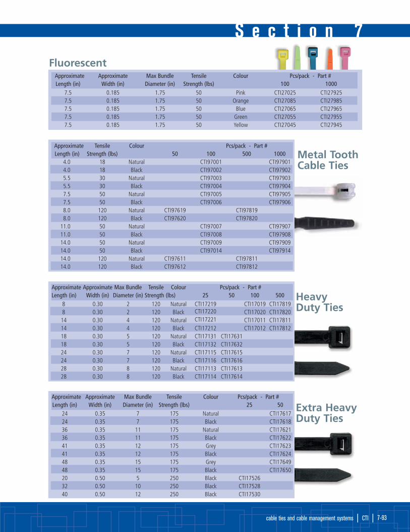
S e c t i o n 7
cable ties and cable management systems | CTI | 7-93
FluorescentApproximate Approximate Max Bundle Tensile Colour Pcs/pack - Part #Length (in) Width (in) Diameter (in) Strength (lbs) 100 1000
7.5 0.185 1.75 50 Pink CTI27025 CTI279257.5 0.185 1.75 50 Orange CTI27085 CTI279857.5 0.185 1.75 50 Blue CTI27065 CTI279657.5 0.185 1.75 50 Green CTI27055 CTI279557.5 0.185 1.75 50 Yellow CTI27045 CTI27945
Metal ToothCable Ties
Approximate Tensile Colour Pcs/pack - Part # Length (in) Strength (lbs) 50 100 500 1000
4.0 18 Natural CTI97001 CTI979014.0 18 Black CTI97002 CTI979025.5 30 Natural CTI97003 CTI979035.5 30 Black CTI97004 CTI979047.5 50 Natural CTI97005 CTI979057.5 50 Black CTI97006 CTI979068.0 120 Natural CTI97619 CTI978198.0 120 Black CTI97620 CTI97820
11.0 50 Natural CTI97007 CTI9790711.0 50 Black CTI97008 CTI9790814.0 50 Natural CTI97009 CTI9790914.0 50 Black CTI97014 CTI9791414.0 120 Natural CTI97611 CTI9781114.0 120 Black CTI97612 CTI97812
HeavyDuty Ties
Approximate Approximate Max Bundle Tensile Colour Pcs/pack - Part # Length (in) Width (in) Diameter (in) Strength (lbs) 25 50 100 500
8 0.30 2 120 Natural CTI17219 CTI17019 CTI178198 0.30 2 120 Black CTI17220 CTI17020 CTI1782014 0.30 4 120 Natural CTI17221 CTI17011 CTI1781114 0.30 4 120 Black CTI17212 CTI17012 CTI1781218 0.30 5 120 Natural CTI17131 CTI1763118 0.30 5 120 Black CTI17132 CTI1763224 0.30 7 120 Natural CTI17115 CTI1761524 0.30 7 120 Black CTI17116 CTI1761628 0.30 8 120 Natural CTI17113 CTI1761328 0.30 8 120 Black CTI17114 CTI17614
Extra HeavyDuty Ties
Approximate Approximate Max Bundle Tensile Colour Pcs/pack - Part # Length (in) Width (in) Diameter (in) Strength (lbs) 25 50
24 0.35 7 175 Natural CTI1761724 0.35 7 175 Black CTI1761836 0.35 11 175 Natural CTI1762136 0.35 11 175 Black CTI1762241 0.35 12 175 Grey CTI1762341 0.35 12 175 Black CTI1762448 0.35 15 175 Grey CTI1764948 0.35 15 175 Black CTI1765020 0.50 5 250 Black CTI1752632 0.50 10 250 Black CTI1752840 0.50 12 250 Black CTI17530

cable ties & cable management systemscable ties & cable management systemsS e c t i o n 7
| CTI | www.cleevetech.com 7-94
Approx. Approx. Max bundle Tensile Colour Pcs/pack - Part #Length (in) Width (in) Diam. (in) Strength (lbs) 100 1000
Releasable6.0 0.30 1.25 50 Black CTI17034 CTI179346.0 0.30 1.25 50 Natural CTI17033 CTI17933
11.75 0.30 3.0 50 Black CTI17036 CTI1793611.75 0.30 3.0 50 Natural CTI17035 CTI17935Identification8.0 0.18 1.75 50 Black CTI17040 CTI179408.0 0.18 1.75 50 Natural CTI17039 CTI17939
Button Head9.625 0.22 2.625 100 Black CTI17042 CTI17942Beaded4.20 1.14 8 Natural CTI17080 CTI17980Cord Band, Ladder Type7.10 1.85 Natural CTI17070 CTI17870
Releasable and Other Special Use Cable Ties1
2
3
4
5
ChromePlatedCable TiesModern style of cable ties
are perfect for custom
shops, bikes and other
customized vehicles.
Pcs/pack - Part # Length (in) Bundle Diameter (in) Strength (lbs) Colour 10 1008 (200 mm) 2 (50 mm) 18 Blue CTI57165 CTI570658 (200 mm) 2 (50 mm) 18 Gold CTI57185 CTI570858 (200 mm) 2 (50 mm) 18 Green CTI57155 CTI570558 (200 mm) 2 (50 mm) 18 Purple CTI57175 CTI570758 (200 mm) 2 (50 mm) 18 Red CTI57125 CTI570258 (200 mm) 2 (50 mm) 18 Silver CTI57105 CTI57005
Max. Bundle Pcs/pack - Part # Length (in) Width (in) Strength (lbs) Diameter 10 1008 (200 mm) 0.187 (4.74 mm) 150 2 (51 mm) CTI67105 CTI6700514 (360 mm) 0.187 (4.74 mm) 150 4 (102 mm) CTI67109 CTI6700920 (510 mm) 0.187 (4.74 mm) 150 6 (152 mm) CTI67111 CTI6701127 (690 mm) 0.187 (4.74 mm) 150 8 (200 mm) CTI67115 CTI6701514 (360 mm) 0.313 (7.94 mm) 250 4 (102 mm) CTI67119 CTI67019
Stainless Steel Cable TiesMade with 316 stainless steel. Resistant to temperature and moisture variations, ideal for high corrosion areas.
Cable Tie Mounting Part # Dimensions (in) Standard packSize (lbs) Screw White Black W L H quantity
4-way (adhesive-backed)18 to 30 #6 CTI27300 CT28300 0.75 0.75 0.21 10018 to 50 #6 CT27400 CT28400 1.00 1.00 0.22 100
2-way (adhesive backing)18 to 150 #6 CT27500 CT28500 1.25 1.25 0.25 100
2-way (no adhesive backing)18 to 50 #8 CT37100 CT38100 0.38 0.60 0.28 10018 to 120 #10 CT37300 CT38300 0.62 0.88 0.39 100
Cable Tie Mounting Bases
1
2
3
4
5

S e c t i o n 7
cable ties and cable management systems | CTI | 7-95
Part # Pcs/Pack
CTI66086 25
CTI66186 100
CTI66886 500
Push Mount Clips• Push mount clip (natural).
• Accepts all cable ties up to 50 lbs tensile strength. For use in 0.250”(6.4 mm) hole. 25 pack.
Cable Tie Application ToolsLT-400
• Heavy duty tool for use with 18-50 lbs ties
• Automatic cut-off and adjustable tensioning
LT-100
• Lightweight tool for use with 18-50 lbs ties
• Cinch tie to desired bundle and twist tool to removeexcess strap
Stainless Steel Tool 62866
• Steel tie gun for tensioning and cut off. Tool is a ball lockand ladder type. For use with our stainless steel ties.
ERG-299 Professional
• Ideal for assembly line use with 18-50 lb. ties
• 360˚ rotatable nose allows use in any position
• Quick tension-adjustment wheel is located towards the frontfor easy access and fast changes
• Adjustable handle
• Light weight with a well balanced centre of gravity andsmooth grip surface
Nylon Cable ClampsNylon cable clamps resist corrosion road salt, gas, oil
and solvents. Available in white or black.
Temperature rating is 85ºC (185ºF).
Part # Mounting Hole ID Size Width Pack
Diameter (in) (in) (in) Qty
White Black ‘H’ ‘D’ ‘W’
CTI22002 CT124002 0.2 (5mm) 1/8 3/8 100
CTI22004 CT124004 0.2 (5mm) 1/4 3/8 100
CTI22005 CT124005 0.2 (5mm) 5/16 3/8 100
CTI22006 CT124006 0.2 (5mm) 3/8 3/8 100
CTI22008 CT124008 0.2 (5mm) 1/2 3/8 100
CTI22010 CT124010 0.2 (5mm) 5/8 3/8 100
CTI22515 CT124515 0.2 (5mm) 1 1/2 50
CTI22518 CT124518 0.2 (5mm) 1-1/4 1/2 50
CTI22520 CT124520 0.2 (5mm) 1-1/2 1/2 50
Steel-Plated NeopreneCable ClampsNeoprene cushion for electrical insulation and vibration
absorption. Neoprene meets specifications MIL R-3065
and AMS-3209. Steel clamps are zinc
electroplated for corrosion
resistance. 10 per pack.
Add ‘-C’ to part number
for 100 piece pack.
Part # Mounting Hole ID Size Width Pack
Diameter (in) (in) (in) Qty
‘H’ ‘D’ ‘W’
CTI66321 0.27 (6.7 mm) 1/4 (6.4 mm) 9/16 (14.3 mm) 10
CTI66322 0.27 (6.7 mm) 3/8 (9.5 mm) 9/16 (14.3 mm) 10
CTI66332 0.41 (10.4 mm) 1/2 (12.7 mm) 3/4 (19.1 mm) 10
CTI66333 0.41 (10.4 mm) 5/8 (15.9 mm) 3/4 (19.1 mm) 10
CTI66334 0.41 (10.4 mm) 3/4 (19.1 mm) 3/4 (19.1 mm) 10
CTI66335 0.41 (10.4 mm) 7/8 (22.2 mm) 3/4 (19.1 mm) 10
CTI66336 0.41 (10.4 mm) 1 (25.4 mm) 3/4 (19.1 mm) 10

cable ties & cable management systemscable ties & cable management systemsS e c t i o n 7
| CTI | www.cleevetech.com 7-96
Loom-Type Steel Clampswith Vinyl CushionThese clamps are ideal for loom,
tubing, and wire and contain
an oval opening for
easy alignment.
Add ‘-C’ to part number
for 100 piece pack.
Part # Mounting Hole ID Width Pack
Diameter (in) Size (in) (in) Qty
CTI66087 9/32 (7.1 mm) 1/2 (12.7 mm) 1/4 (6.4 mm) 10
CTI66088 9/32 (7.1 mm) 1/2 (12.7 mm) 3/8 (9.5 mm) 10
CTI66089 9/32 (7.1 mm) 1/2 (12.7 mm) 1/2 (12.7 mm) 10
CTI66090 9/32 (7.1 mm) 1/2 (12.7 mm) 5/8 (15.9 mm) 10
CTI66091 9/32 (7.1 mm) 1/2 (12.7 mm) 3/4 (19.1 mm) 10
CTI66092 9/32 (7.1 mm) 1/2 (12.7 mm) 1 (25.4 mm) 10
CTI66093 9/32 (7.1 mm) 1/2 (12.7 mm) 1-1/2 (38.1 mm) 10
GrommetsGrommets protect wires and
cables passing through panels
while resisting oils and grease.
They can also withstand
temperatures from -40ºC to
135ºC. Also available
#CTI18500 25 pc assortment.
Part Hole Size Inside Panel Outside Grommet Pack
# ‘H’ Diameter ‘ID’ Thickness ‘P’ Diameter ‘OD’ Thickness ‘T’ Qty
CTI18301 6.4 4.0 1.6 9.5 6.4 25
CTI18302 6.4 4.8 3.2 9.5 8.7 25
CTI18303 7.5 4.0 2.4 10.3 38.9 25
CTI18304 7.9 4.8 4.8 14.7 28.6 25
CTI18305 9.5 7.9 1.6 14.3 7.9 25
CTI18306 12.7 7.9 3.2 19.1 9.5 25
CTI18307 12.7 7.9 1.6 19.0 7.9 25
CTI18308 15.9 11.1 0.8 19.1 9.5 25
CTI18309 15.9 12.7 1.2 20.6 5.1 25
CTI18310 19.1 11.9 1.6 25.4 7.9 25
CTI18311 19.1 14.3 3.0 25.4 9.5 25
CTI18312 20.0 16.0 1.6 31.8 7.9 25
CTI18313 25.4 19.1 1.6 31.8 7.9 25
CTI18314 25.4 22.2 1.6 31.8 7.9 25
CTI18315 28.6 22.2 3.2 34.9 9.5 25
Thermafix SolderSplice™ wire-to-wire splices feature a fluxed solder preform
within a heat shrinkable thermoplastic sleeve. This provides a completely
soldered, strain-relieved, encapsulated connection. The one-piece, one-step
design simplifies installation.
• Controlled soldering combined with shrink tubing in one-step
• Strain relief
• Max operating temperatures to 125°C (257°F)
• Colour-coded sealing rings
• Transparent sleeves easy to inspect
Triple action:
• Sleeve shrinks
• Center ring of solder melts to connect
• Outer rings of colour-coded plastic seal
Thermafix SolderSpliceTM Wire-to-Wire Splices

S e c t i o n 7
cable ties and cable management systems | CTI | 7-97
Thermafix CrimpTM
Heat Shrinkable and adhesive-lined, Thermafix Crimp™
products insulate and protect electrical connections from
mechanical abuse, wire pull-out, and abrasion while resisting
water, salt, and other contaminants.
• Rugged, heat shrinkable nylon
• Hot melt adhesive lining
• Transparent for easy installation
• Extended temp. range of -55˚C to 125˚C
• Colour-coded for AWG 22 to 10
• High strength crimp barrels
C
Butt Splices
Convenience PacksPcs/pack Part #
18 CTI26004
100 CTI26104Bulk PackPcs/pack Part #
1000 CTI26904
Convenience PacksPcs/pack Part #
18 CTI26005
100 CTI26105Bulk PackPcs/pack Part Number
1000 CTI26905
Convenience PacksPcs/pack Part #
12 CTI26006
50 CTI26106Bulk PackPcs/pack Part Number
500 CTI26806
Wire Gauge 22-18 Wire Gauge 12-10 Wire Gauge 16-14
Convenience PacksPcs/pack Part #
18 CTI16004
100 CTI16104Bulk PackPcs/pack Part #1000 CTI16904
Convenience PacksPcs/pack Part #
18 CTI16005
100 CTI16105Bulk PackPcs/ pack Part #
1000 CTI16905
Convenience PacksPcs/pack Part #12 CTI16006
50 CTI16106Bulk PackPcs/ pack Part #
500 CTI16806
Wire Gauge 22-18 Wire Gauge 12-10
Convenience PacksPcs/pack Part #
18 CTI16001
Butt Splice Assorted
Convenience PacksPcs/pack Part #
18 CTI16002
Terminals Assorted
Wire Gauge 16-14

cable ties & cable management systemscable ties & cable management systemsS e c t i o n 7
| CTI | www.cleevetech.com 7-98
Thermafix CrimpTMPart Numbers and Pack Sizes for Standard Shapes
Convenience PacksPcs/pack Part #18 CTI16023100 CTI16123Bulk PackPcs/pack Part #1000 CTI16923
#8 Wire Gauge 22-18
Convenience PacksPcs/pack Part #18 CTI16007100 CTI16107Bulk PackPcs/pack Part #1000 CTI16907
#10 Wire Gauge 22-18
Convenience PacksPcs/pack Part #18 CTI16025100 CTI16125Bulk PackPcs/pack Part #1000 CTI16925
1/4 Wire Gauge 22-18
Convenience PacksPcs/pack Part #18 CTI1603075 CTI16130Bulk PackPcs/pack Part #1000 CTI16930
5/16 Wire Gauge 22-18
Convenience PacksPcs/pack Part #18 CTI1602775 CTI16127Bulk PackPcs/pack Part #1000 CTI16927
#8 Wire Gauge 22-18
Convenience PacksPcs/pack Part #18 CTI16024100 CTI16124Bulk PackPcs/pack Part #1000 CTI16924
#8 Wire Gauge 16-14
Convenience PacksPcs/pack Part #18 CTI16009100 CTI16109Bulk PackPcs/pack Part #1000 CTI16909
#8 Wire Gauge 16-14
Convenience PacksPcs/pack Part #18 CTI16026100 CTI16126Bulk PackPcs/pack Part #1000 CTI16926
1/4 Wire Gauge 16-14
Convenience PacksPcs/pack Part #18 CTI1601775 CTI16117Bulk PackPcs/pack Part #1000 CTI16917
5/16 Wire Gauge 16-14
Convenience PacksPcs/pack Part #18 CTI1602175 CTI16121Bulk PackPcs/pack Part #1000 CTI16921
3/8 Wire Gauge 16-14
Convenience PacksPcs/pack Part #12 CTI1602050 CTI16120Bulk PackPcs/pack Part #500 CTI16820
#8 Wire Gauge 12-10
Convenience PacksPcs/pack Part #12 CTI1601950 CTI16119Bulk PackPcs/pack Part #500 CTI16819
#8 Wire Gauge 12-10
Convenience PacksPcs/pack Part #12 CTI1601150 CTI16111Bulk PackPcs/pack Part #500 CTI16811
#8 Wire Gauge 12-10
Convenience PacksPcs/pack Part #12 CTI1601850 CTI16118Bulk PackPcs/pack Part #500 CTI16818
#8 Wire Gauge 12-10
Convenience PacksPcs/pack Part #12 CTI1602250 CTI16122Bulk PackPcs/pack Part #500 CTI16822
#8 Wire Gauge 12-10
Convenience PacksPcs/pack Part #18 CTI16008100 CTI16108Bulk PackPcs/pack Part #1000 CTI16908
#8 Wire Gauge 22-18
Convenience PacksPcs/pack Part #18 CTI16010100 CTI16110Bulk PackPcs/pack Part #1000 CTI16910
#8 Wire Gauge 16-14
Convenience PacksPcs/pack Part #12 CTI1601250 CTI16112Bulk PackPcs/pack Part #500 CTI16812
#8 Wire Gauge 12-10
Ring Terminal
Spade Terminal

S e c t i o n 7
cable ties and cable management systems | CTI | 7-99
Convenience PacksPcs/pack Part #18 CTI1602875 CTI16128Bulk PackPcs/pack Part #1000 CTI16928
Male Wire Gauge 16-14
Convenience PacksPcs/pack Part #18 CTI1602975 CTI16129Bulk PackPcs/pack Part #1000 CTI16929
Female Wire Gauge 16-14
Convenience PacksPcs/pack Part #18 CTI1601375 CTI16113Bulk PackPcs/pack Part #1000 CTI16913
Female Wire Gauge 22-18
Convenience PacksPcs/pack Part #18 CTI1601475 CTI16114Bulk PackPcs/pack Part #1000 CTI16914
Female Wire Gauge 16-14
Convenience PacksPcs/pack Part #18 CTI1601375 CTI16113Bulk PackPcs/pack Part #1000 CTI16913
Female Wire Gauge 22-18
Convenience PacksPcs/pack Part #18 CTI1601475 CTI16114Bulk PackPcs/pack Part #1000 CTI16914
Female Wire Gauge 16-14
Convenience PacksPcs/pack Part #12 CTI1603150 CTI16131Bulk PackPcs/pack Part #500 CTI16831
Female Wire Gauge 12-10
Bullet Terminal
Quick Disconnect
Installation Tip
Use of reflector tip attach-
ment will improve the
installation of heat shrink
terminals.
Heat Shrink Assortments
Assortment Part # CTI10002
ThermafixTM Single Wall 167 pcs (1/8-3/4 black & red)
Dual Wall ThermafixTM Plus 10 pcs (all sizes)
Heavy Wall ThermafixTM ST 4 pcs (1.1” diameter)
Thermafix CrimpTM Terminals 18 pcs (assorted)
Thermafix CrimpTM Splices 18 pcs (assorted)
Cable Ties 40 pcs (black & white)
*Starter refill for CTI10002 is available as number CTI10012(single wall only).
Assortment Part # CTI10007
Thermafix CrimpTM Terminals 252 pcs (blue,yellow & red-21 types)
Thermafix CrimpTM Splices 36 pcs (blue, yellow & red)

cable ties & cable management systemscable ties & cable management systemsS e c t i o n 7
| CTI | www.cleevetech.com 7-100
Heat Shrink Assortments Continued
Assortment Part # CTI10003
ThermafixTM Single Wall 166 pcs (1/8-3/8 black & red)
Dual Wall ThermafixTM Plus 26 pcs (sizes 1 & 2)
Thermafix CrimpTM Terminals 66 pcs (blue & yellow - 4 types)
Thermafix CrimpTM Splices 30 pcs (blue & yellow)
Assortment Part # CTI10008
Dual Wall ThermafixTM Plus 27 pcs (sizes 1, 2, 3 & 4)
Thermafix CrimpTM Terminals 40 pcs (blue, yellow & red)
Thermafix CrimpTM Splices 36 pcs (blue & yellow)
Assortment Part # CTI10004
ThermafixTM Single Wall 36 pcs (1/8”-3/16” & 1/4 red, yellow, blue,green, black, white)
Dual Wall ThermafixTM Plus 25 pcs (sizes 1, 2 & 3)
Assortment Part # CTI10009
Dual Wall ThermafixTM Plus 62 pcs (sizes 1, 2 & 3)
Assortment Part # CTI10005
Thermafix CrimpTM Terminals 325 pcs (blue & yellow, 13 types)
Thermafix CrimpTM Splices 100 pcs (blue & yellow)
Assortment Part # CTI10010
Dual Wall ThermafixTM Plus 63 pcs (all sizes)

S e c t i o n 7
cable ties and cable management systems | CTI | 7-101
Primary Terminals & Connectors• Pure electrolytic copper with electro-tin plating for corrosion resistance
• Deep internal serrations promote firm wire grip for maximum strength
• Insulation (where applicable) is colour coded to NEMA standards and flared for easy insertion of stranded and solid wire
Which Terminal / Connector to Choose?Non-Insulated, PVC Insulated, Nylon Insulated or High Temperature
N O N - I N S U L A T E Dterminals are used wherethere is no worry about‘grounding’ or ‘shortingout’ against other wiresor metal frames, or withheat shrink tubing tocover the connectionafter seeing that it hasbeen made properly.
PVC insulated terminals aremanufactured using a two-partconstruction; an inner lug covered with a friction fit PVC sleeve. Generally speakinga single crimp is sufficient tomake a proper connection.
NYLON insulated terminals are manufactured using a three-part construction: an inner lug, a copper sleeve, and an outer Nylon coating. The copper sleeve acts as a ‘funnel’ to direct the wire properly into the lug. Generally a dual crimp is utilized—one whichcrimps the inner lug, one which crimps the sleeve.
This connection is regarded as a better design as it gives strain reliefat the connection and subsequently less fatigue
Both NYLON and PVC connections are rated at 90˚C to 105˚C and canbe used in auto applications (12V) or AC (110V). The actual rating of each is up to 600V. Both NYLON and PVC offer excellent protection from surrounding metal or wire contact to prevent “shorting out” situations.
High Temperature terminals arenickel plated and excellent forhigh-heat applications, able towithstand temperatures of up to 900ºF (482ºC).
Pcs/pack Part #15 CTI7521170 CTI772111000 CTI87211
1/4” Wire Gauge 22-18
Pcs/pack Part #25 CTI75209200 CTI772091000 CTI87209
#10 Wire Gauge 22-18
Pcs/pack Part #25 CTI75217100 CTI772171000 CTI87217
#10 Wire Gauge 16-14
Pcs/pack Part #25 CTI75219100 CTI772191000 CTI87219
#10 Wire Gauge 16-14
Pcs/pack Part #25 CTI75215100 CTI772151000 CTI87215
#8 Wire Gauge 22-18
Pcs/pack Part #25 CTI75213100 CTI772131000 CTI87213
#6 Wire Gauge 22-18
Non-InsulatedRingTerminals
Pcs/pack Part #15 CTI7522570 CTI772251000 CTI87225
#6 Wire Gauge 12-10
Pcs/pack Part #15 CTI7522770 CTI772271000 CTI87227
#8 Wire Gauge 12-10
Pcs/pack Part #25 CTI7522370 CTI772231000 CTI87223
#10 Wire Gauge 12-10
Pcs/pack Part #25 CTI75221100 CTI772211000 CTI87221
#8 Wire Gauge 16-14
Pcs/pack Part #25 CTI75117100 CTI771171000 CTI87117
#6 S Wire Gauge 22-18
Pcs/pack Part #25 CTI75115100 CTI771151000 CTI87115
#6 Wire Gauge 22-18
Pcs/pack Part #25 CTI75113100 CTI771131000 CTI87113
#10 Wire Gauge 22-18 Non-InsulatedSpadeTerminals

cable ties & cable management systemscable ties & cable management systemsS e c t i o n 7
| CTI | www.cleevetech.com 7-102
Pcs/pack Part #25 CTI75121100 CTI771211000 CTI87121
#10 Wire Gauge 16-14
Pcs/pack Part #25 CTI75119100 CTI771191000 CTI87119
#8 Wire Gauge 22-18
Pcs/pack Part #25 CTI7512970 CTI771291000 CTI87129
#10 Wire Gauge 12-10
Pcs/pack Part #25 CTI75123100 CTI771231000 CTI87123
#6 Wire Gauge 16-14
Pcs/pack Part #25 CTI75127100 CTI771271000 CTI87127
#8 Wire Gauge 16-14
Pcs/pack Part #25 CTI75215100 CTI772151000 CTI87215
#6 S Wire Gauge 16-14
Non-InsulatedSpade
TerminalsContinued
Pcs/pack Part #25 CTI7548590 CTI774851000 CTI87485
1/4” Wire Gauge 12-10
Pcs/pack Part #25 CTI75483100 CTI774831000 CTI87483
1/4” Wire Gauge 16-14
Pcs/pack Part #25 CTI75481100 CTI774811000 CTI87481
1/4” Wire Gauge 16-14
Pcs/pack Part #15 CTI7518170 CTI771811000 CTI87181
1/4” Wire Gauge 12-10
Pcs/pack Part #20 CTI7517980 CTI771791000 CTI87179
1/4” Wire Gauge 16-14
Pcs/pack Part #20 CTI7517780 CTI771771000 CTI87177
1/4” Wire Gauge 22-18
Pcs/pack Part #8 CTI7517535 CTI771751000 CTI87175
1/4” Wire Gauge 12-10
Pcs/pack Part #15 CTI7517370 CTI771731000 CTI87173
1/4” Wire Gauge 16-14
Pcs/pack Part #15 CTI7517170 CTI771711000 CTI87171
1/4” Wire Gauge 22-18
Pcs/pack Part #15 CTI7511170 CTI771111000 CTI87111
Wire Gauge 12-10
Pcs/pack Part #25 CTI75109100 CTI771091000 CTI87109
Wire Gauge 16-14
Pcs/pack Part #25 CTI75107100 CTI771071000 CTI87107
Wire Gauge 22-18
Pcs/pack Part #15 CTI7546550 CTI774651000 CTI87465
Wire Gauge 12-10
Pcs/pack Part #25 CTI75463100 CTI774631000 CTI87463
Wire Gauge 16-14
Pcs/pack Part #25 CTI75461100 CTI774611000 CTI87461
Wire Gauge 22-18
Non-Insulated
MaleDisconnects
Non-Insulated
FemaleDisconnects
Non-Insulated
FlagTerminals
Non-Insulated
Butt SpliceConnectors
Non-InsulatedSeamless
Butt SpliceConnectors

S e c t i o n 7
cable ties and cable management systems | CTI | 7-103
Pcs/pack Part #15 CTI7523170 CTI772311000 CTI87231
1/4” Wire Gauge 22-18
Pcs/pack Part #25 CTI75229100 CTI772291000 CTI87229
#10 Wire Gauge 22-18
Pcs/pack Part #25 CTI75237100 CTI772371000 CTI87237
#6 Wire Gauge 22-18
Pcs/pack Part #15 CTI7523570 CTI772351000 CTI87235
5/16” Wire Gauge 22-18
Pcs/pack Part #15 CTI7523370 CTI772331000 CTI87233
3/8” Wire Gauge 22-18
Pcs/pack Part #15 CTI7524570 CTI772451000 CTI87245
3/8” Wire Gauge 16-14
Pcs/pack Part #15 CTI7524370 CTI772431000 CTI87243
1/4” Wire Gauge 16-14
Pcs/pack Part #25 CTI75241100 CTI772411000 CTI87241
#10 Wire Gauge 16-14
Pcs/pack Part #20 CTI7525380 CTI772531000 CTI87253
#10 Wire Gauge 12-10
Pcs/pack Part #25 CTI75251100 CTI772511000 CTI87251
#8 Wire Gauge 16-14
Pcs/pack Part #25 CTI75249100 CTI772491000 CTI87249
#6 Wire Gauge 16-14
Pcs/pack Part #20 CTI7526180 CTI772611000 CTI87261
#6 Wire Gauge 12-10
Pcs/pack Part #15 CTI7525970 CTI772591000 CTI87259
15/16” Wire Gauge 12-10
Pcs/pack Part #15 CTI7525770 CTI772571000 CTI87257
3/8” Wire Gauge 12-10
Pcs/pack Part #25 CTI75135100 CTI771351000 CTI87135
#6 S Wire Gauge 22-18
Pcs/pack Part #25 CTI75133100 CTI771331000 CTI87133
#6 Wire Gauge 22-18
Pcs/pack Part #25 CTI75131100 CTI771311000 CTI87131
#10 Wire Gauge 22-18
Pcs/pack Part #25 CTI75141100 CTI771411000 CTI87141
#6 Wire Gauge 16-14
Pcs/pack Part #25 CTI75239100 CTI772391000 CTI87239
#8 Wire Gauge 22-18
Pcs/pack Part #15 CTI7524770 CTI772471000 CTI87247
15/16” Wire Gauge 16-14
Pcs/pack Part #15 CTI7525570 CTI772551000 CTI87255
1/4” Wire Gauge 12-10
Pcs/pack Part #20 CTI7526380 CTI772631000 CTI87263
#8 Wire Gauge 12-10
Pcs/pack Part #25 CTI75143100 CTI771431000 CTI87143
#6 S Wire Gauge 16-14
Pcs/pack Part #25 CTI75139100 CTI771391000 CTI87139
#10 Wire Gauge 16-14
Pcs/pack Part #25 CTI75137100 CTI771371000 CTI87137
#8 Wire Gauge 22-18
PVC RingTerminals
PVC SpadeTerminals
S e c t i o n 7
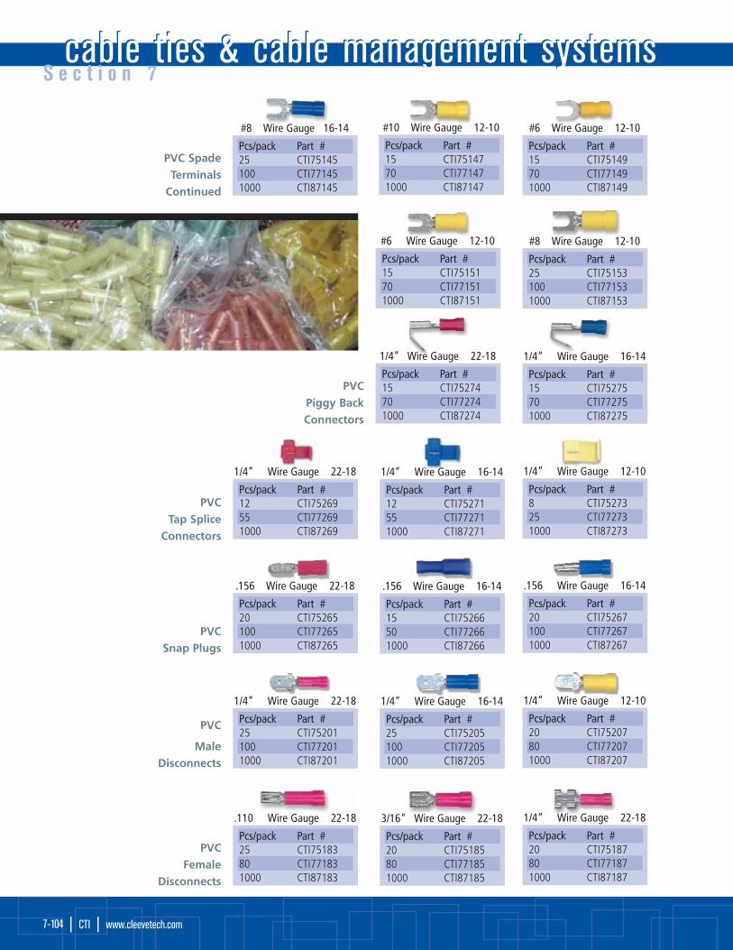
cable ties & cable management systemscable ties & cable management systemsS e c t i o n 7
| CTI | www.cleevetech.com 7-104
Pcs/pack Part #15 CTI7514770 CTI771471000 CTI87147
#10 Wire Gauge 12-10
Pcs/pack Part #25 CTI75145100 CTI771451000 CTI87145
#8 Wire Gauge 16-14
Pcs/pack Part #15 CTI7514970 CTI771491000 CTI87149
#6 Wire Gauge 12-10
Pcs/pack Part #25 CTI75153100 CTI771531000 CTI87153
#8 Wire Gauge 12-10
Pcs/pack Part #15 CTI7515170 CTI771511000 CTI87151
#6 Wire Gauge 12-10
PVC SpadeTerminals
Continued
Pcs/pack Part #15 CTI7527570 CTI772751000 CTI87275
1/4” Wire Gauge 16-14
Pcs/pack Part #15 CTI7527470 CTI772741000 CTI87274
1/4” Wire Gauge 22-18
Pcs/pack Part #8 CTI7527325 CTI772731000 CTI87273
1/4” Wire Gauge 12-10
Pcs/pack Part #12 CTI7527155 CTI772711000 CTI87271
1/4” Wire Gauge 16-14
Pcs/pack Part #12 CTI7526955 CTI772691000 CTI87269
1/4” Wire Gauge 22-18
Pcs/pack Part #20 CTI75267100 CTI772671000 CTI87267
.156 Wire Gauge 16-14
Pcs/pack Part #15 CTI7526650 CTI772661000 CTI87266
.156 Wire Gauge 16-14
Pcs/pack Part #20 CTI75265100 CTI772651000 CTI87265
.156 Wire Gauge 22-18
Pcs/pack Part #20 CTI7520780 CTI772071000 CTI87207
1/4” Wire Gauge 12-10
Pcs/pack Part #25 CTI75205100 CTI772051000 CTI87205
1/4” Wire Gauge 16-14
Pcs/pack Part #25 CTI75201100 CTI772011000 CTI87201
1/4” Wire Gauge 22-18
Pcs/pack Part #20 CTI7518780 CTI771871000 CTI87187
1/4” Wire Gauge 22-18
Pcs/pack Part #20 CTI7518580 CTI771851000 CTI87185
3/16” Wire Gauge 22-18
Pcs/pack Part #25 CTI7518380 CTI771831000 CTI87183
.110 Wire Gauge 22-18
PVC Piggy BackConnectors
PVC Tap Splice
Connectors
PVC Snap Plugs
PVC
MaleDisconnects
PVC Female
Disconnects

S e c t i o n 7
cable ties and cable management systems | CTI | 7-105
Pcs/pack Part #25 CTI75193100 CTI771931000 CTI87193
1/4” Wire Gauge 16-14
Pcs/pack Part #25 CTI75191100 CTI771911000 CTI87191
3/16” Wire Gauge 16-14
Pcs/pack Part #20 CTI7518980 CTI771891000 CTI87189
.110 Wire Gauge 16-14
Pcs/pack Part #25 CTI75195100 CTI771951000 CTI87195
1/4” Wire Gauge 12-10
Pcs/pack Part #15 CTI7510570 CTI771051000 CTI87105
Wire Gauge 12-10
Pcs/pack Part #25 CTI75103100 CTI771031000 CTI87103
Wire Gauge 16-14
Pcs/pack Part #25 CTI75101100 CTI771011000 CTI87101
Wire Gauge 16-14
Pcs/pack Part #15 CTI7527770 CTI772771000 CTI87277
Wire Gauge 16-10
Pcs/pack Part #25 CTI75276100 CTI772761000 CTI87276
Wire Gauge 22-14
Pcs/pack Part #15 CTI7541170 CTI774111000 CTI87411
#10 Wire Gauge 16-14
Pcs/pack Part #25 CTI75410100 CTI774101000 CTI87410
#6 Wire Gauge 16-14
Pcs/pack Part #15 CTI7541465 CTI774141000 CTI87414
1/4” Wire Gauge 22-18
Pcs/pack Part #20 CTI7541375 CTI774131000 CTI87413
#6 Wire Gauge 22-18
Pcs/pack Part #20 CTI7541270 CTI774121000 CTI87412
#10 Wire Gauge 12-10
Pcs/pack Part #15 CTI7541750 CTI774171000 CTI87417
1/2” Wire Gauge 12-10
Pcs/pack Part #15 CTI7541665 CTI774161000 CTI87416
3/8” Wire Gauge 12-10
Pcs/pack Part #15 CTI7541565 CTI774151000 CTI87415
3/8 Wire Gauge 16-14
PVC RingTerminals
PVC ButtSpliceConnectors
PVC Closed EndConnectors
Nylon RingTerminals

cable ties & cable management systemscable ties & cable management systemsS e c t i o n 7
| CTI | www.cleevetech.com 7-106
Pcs/pack Part #15 CTI7544160 CTI774411000 CTI87441
1/4” Wire Gauge 12-10
Pcs/pack Part #15 CTI7544360 CTI774431000 CTI87443
3/8” Wire Gauge 12-10
Pcs/pack Part #20 CTI7541975 CTI774191000 CTI87419
#10 Wire Gauge 12-10
Pcs/pack Part #25 CTI75418100 CTI774181000 CTI87418
#10 Wire Gauge 16-14
Nylon Heavy Duty
Terminal
Nylon Spade
Terminal
Pcs/pack Part #20 CTI7549380 CTI774931000 CTI87493
1/4” Wire Gauge 22-18
Pcs/pack Part #20 CTI7549180 CTI774911000 CTI87491
1/4” Wire Gauge 16-14
Pcs/pack Part #15 CTI7545160 CTI774511000 CTI87451
1/4” Wire Gauge 12-10
Pcs/pack Part #15 CTI7545360 CTI774531000 CTI87453
1/4” Wire Gauge 12-10
Pcs/pack Part #8 CTI7515935 CTI771591000 CTI87159
3/16 Wire Gauge 16-14
Pcs/pack Part #8 CTI7515535 CTI771551000 CTI87155
3/16 Wire Gauge 22-18
Pcs/pack Part #20 CTI7548980 CTI774891000 CTI87489
1/4” Wire Gauge 16-14
Pcs/pack Part #20 CTI7548780 CTI774871000 CTI87487
1/4” Wire Gauge 22-18
Pcs/pack Part #25 CTI75401100 CTI774011000 CTI87401
1/4” Wire Gauge 16-14
Pcs/pack Part #4 CTI7547517 CTI774751000 CTI87475
1/4” Wire Gauge 12-10
Pcs/pack Part #10 CTI7547350 CTI774731000 CTI87473
1/4” Wire Gauge 16-14
Pcs/pack Part #20 CTI7547170 CTI774711000 CTI87471
1/4” Wire Gauge 22-18
Nylon FullyInsulated
MaleDisconnects
Nylon FullyInsulated
FemaleDisconnects
Nylon Male
Disconnects
Nylon Flag
Terminals

S e c t i o n 7
cable ties and cable management systems | CTI | 7-107
Pcs/pack Part #20 CTI7542975 CTI774291000 CTI87429
Wire Gauge 12-10
Pcs/pack Part #25 CTI75427100 CTI774271000 CTI87427
Wire Gauge 16-14
Pcs/pack Part #25 CTI75425100 CTI774251000 CTI87425
Wire Gauge 22-18
Pcs/pack Part #5 CTI7543520 CTI774351000 CTI87435
1/4” Wire Gauge 16-14
Pcs/pack Part #100 CTI773051000 CTI87305
Wire Gauge 12-10
Pcs/pack Part #100 CTI773031000 CTI87303
Wire Gauge 16-14
Pcs/pack Part #100 CTI773011000 CTI87301
Pcs/pack Part #100 CTI773111000 CTI87311
Pcs/pack Part #100 CTI773091000 CTI87309
Pcs/pack Part #100 CTI773071000 CTI87307
Pcs/pack Part #100 CTI773151000 CTI87315
Pcs/pack Part #100 CTI773141000 CTI87314
Pcs/pack Part #100 CTI773131000 CTI87313
Pcs/pack Part #100 CTI773251000 CTI87325
Pcs/pack Part #100 CTI773271000 CTI87327
Pcs/pack Part #100 CTI773231000 CTI87323
Pcs/pack Part #100 CTI773211000 CTI87321
Wire Gauge 22-18
#10 Wire Gauge 16-14 #10 Wire Gauge 22-18
1/4” Wire Gauge 22-18
#10 Wire Gauge 12-10
#6 Wire Gauge 22-18 #10 Wire Gauge 22-18
#10 Wire Gauge 12-10 3/8” Wire Gauge 12-10 1/4” Wire Gauge 12-10 #8 Wire Gauge 16-14
Pcs/pack Part #100 CTI773181000 CTI87318
Pcs/pack Part #100 CTI773191000 CTI87319
Pcs/pack Part #100 CTI773171000 CTI87317
Pcs/pack Part #100 CTI773161000 CTI87316
1/4” Wire Gauge 16-14 #6 Wire Gauge 16-14 #10 Wire Gauge 16-14 #8 Wire Gauge 22-18
Nylon Butt SpliceConnectors
Non-InsulatedHigh TempButt SpliceConnectors
Non-Insulated HighTemp SpadeRing Connectors
Non-InsulatedHigh Temp Ring Connectors
Nylon 3-WaySplice

cable ties & cable management systemscable ties & cable management systemsS e c t i o n 7
| CTI | www.cleevetech.com 7-108
Pcs/pack Part #100 CTI773331000 CTI87333
#8 Wire Gauge 12-10
Pcs/pack Part #100 CTI773311000 CTI87331
#6 Wire Gauge 12-10
Pcs/pack Part #100 CTI773291000 CTI87329
Pcs/pack Part #100 CTI773391000 CTI87339
Pcs/pack Part #100 CTI773371000 CTI87337
Pcs/pack Part #100 CTI773351000 CTI87335
Pcs/pack Part #100 CTI773451000 CTI87345
Pcs/pack Part #100 CTI773431000 CTI87343
Pcs/pack Part #25 CTI18420100 CTI184501000 CTI18490
Pcs/pack Part #25 CTI18320100 CTI183501000 CTI18390
Pcs/pack Part #25 CTI18220100 CTI182501000 CTI18290
Part # Qty Part # Qty Part # QtyCTI75101 25 CTI75491 10 CTI75245 15CTI75103 25 CTI75193 25 CTI75253 20CTI75105 15 CTI75205 25 CTI75255 15CTI75139 25 CTI75229 25 CTI75257 15CTI75147 15 CTI75241 25 CTI75271 12CTI75489 10 CTI75243 15 CTI75277 15
5/16” Wire Gauge 12-10
1/4” Wire Gauge 16-14 1/4” Wire Gauge 22-18
1/4” Wire Gauge 16-14
1/4” Wire Gauge 12-10
1/4” Wire Gauge 12-10
Min: 2 #14 Ga. Max: 3 #10 & 1 #12 Ga.Min: 2 #14 Ga. Max: 3 #12 Ga.Min: 2 #18 Ga. Max: 2 #14 Ga.
Pcs/pack Part #100 CTI773511000 CTI87351
Pcs/pack Part #100 CTI773491000 CTI87349
Pcs/pack Part #100 CTI773471000 CTI87347
1/4” Wire Gauge 12-101/4” Wire Gauge 16-14 1/4” Wire Gauge 22-18
Non-InsulatedHigh Temp Ring
Connectors(continued)
Non-InsulatedHigh Temp
FemaleDisconnects
Non-Insulated High
Temp MaleDisconnects
Non-Insulated
High TempFlag Terminals
Colour Coded Wire
Nuts
Terminal AssortmentTerminal Assortment in Plastic Storage Box
Comes complete with 332 terminals in 18 of the most popular styles. Each part
number is indexed on the reference chart for ease of identification and quick
reorder. Part #CTI10077

S e c t i o n 7
cable ties and cable management systems | CTI | 7-109
Toggle Switches: Light, Medium, Heavy-Duty
Terminal HandlePart # Duty Position Type Type # Rating Type Colour Pole Throw
CTI65075 Light ON-OFF Screw 2 35 a @ 6V; 20 a @ 12V Bat Chrome Single Single
CTI65072 Light OFF-ON Screw 2 6 a @ 125 volts; 3 a @ 250 volts Bat Nickel Single Single
CTI65073 Light OFF-ON Leads* 2 6 a @ 125 volts; 3 a @ 250 volts Bat Nickel Single Single
CTI65046 Medium ON-OFF Screw 2 20 a @ 12VDC Standard Chrome Single Single
CTI65047 Medium ON-OFF Blade 2 20 a @ 12VDC Standard Chrome Single Single
CTI65048 Medium ON-MOM. OFF Screw 2 20 a @ 12VDC Long Chrome Single Single
CTI65049 Medium MOM. ON -OFF Screw 2 20 a @ 12VDC Standard Chrome Single Single
CTI65054 Medium ON-ON Screw 3 20 a @ 12VDC Standard Chrome Single Double
CTI65055 Medium ON-OFF-ON Screw 3 20 a @ 12VDC Standard Chrome Single Double
CTI65056 Medium ON-OFF-ON Blade 3 20 a @ 12VDC Standard Chrome Single Double
CTI65057 Medium MOM. ON-OFF-MOM. ON Screw 3 20 a @ 12VDC Standard Chrome Single Double
CTI65058 Medium ON-OFF Screw 4 20 a @ 12VDC Standard Chrome Double Single
CTI65059 Medium ON-OFF Blade 4 20 a @ 12VDC Standard Chrome Double Single
CTI65064 Medium ON-ON Screw 6 20 a @ 12VDC Standard Chrome Double Double
CTI65065 Medium ON-OFF-ON Screw 6 20 a @ 12VDC Standard Chrome Double Double
CTI65066 Medium ON-OFF-ON Blade 6 20 a @ 12VDC Standard Chrome Double Double
CTI65067 Medium MOM. ON-OFF-MOM. ON Screw 6 20 a @ 12VDC Standard Chrome Double Double
CTI65012 Heavy ON-OFF Screw 2 50 a @ 6-24volts Standard Black Single Single
CTI65030 Heavy ON-OFF Screw 2 50 a @ 6-24volts Standard Chrome Single Single
CTI65031 Heavy ON-OFF Screw 2 50 a @ 6-24volts Long Chrome Single Single
CTI65033 Heavy ON-OFF Blade 2 30 a @ 6-24volts Standard Chrome Single Single
CTI65020 Heavy MOM. ON-OFF-MOM. ON Screw 3 50 a @ 6-24volts Long Chrome Single Double
CTI65032 Heavy MOM. ON-OFF-MOM. ON Screw 3 50 a @ 6-24volts Standard Chrome Single Double
CTI65034 Heavy ON-OFF-ON Screw 3 50 a @ 6-24volts Standard Chrome Single Double
CTI65210 X-Heavy ON-ON Blade 6 10 a @ 277V; 20 a @ 125V Bat Nickel Single Single
# 65058 # 65072 # 65012 # 65020
# 65100 # 65120 # 65103 # 65114
# 65210
Nylon Handle (with & without light)
Terminal Handle
Part # Position Type # Type Rating Style Colour Pole Throw
CTI65100 ON-OFF 2 Screw 35 a @ 12VDC Decorator Black Single Single
CTI65101 ON-OFF 2 Blade 35 a @ 12VDC Bat Black Single Single
CTI65102 ON-OFF 2 Screw 20 a @ 12VDC Decorator w/Light Single Single
CTI65103 ON-OFF 4 Screw 20 a @ 12VDC Decorator w/Light Single Single
CTI65104 MOM. ON-OFF-MOM. ON 3 Screw 35 a @ 12VDC Decorator Black Single Double
CTI65105 MOM. ON-OFF-MOM. ON 3 Blade 35 a @ 12VDC Decorator Black Single Double
CTI65106 ON-OFF-ON 5 Blade 20 a @ 12VDC Decorator w/Light Single Double
CTI65107 ON-OFF-ON 5 Blade 20 a @ 12VDC Decorator w/Light Single Double
CTI65114 ON-OFF-ON 6 Screw 35 a @ 12VDC Bat Black Double Double
CTI65115 ON-OFF-ON 6 Blade 35 a @ 12VDC Decorator Black Double Double
CTI65116 MOM. ON-OFF-MOM. ON 6 Screw 35 a @ 12VDC Decorator Black Double Double
CTI65117 MOM. ON-OFF-MOM. ON 6 Blade 35 a @ 12VDC Bat Black Double Double
CTI65120 ON-OFF 2 Blade 20 a @ 12VDC Duckbill Black Single Single
CTI65121 ON-OFF 3 Blade 20 a @ 12VDC Duckbill Black Single Single
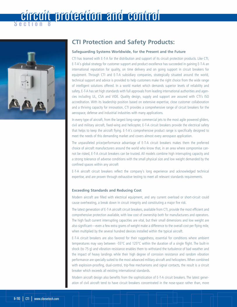
CTI Protection and Safety Products:Safeguarding Systems Worldwide, for the Present and the Future
CTI has teamed with E-T-A for the distribution and support of its circuit protection products. Like CTI,
E-T-A's global strategy for customer support and product excellence has succeeded in gaining E-T-A an
international reputation for quality, on time delivery and on going support in circuit breakers for
equipment. Through CTI and E-T-A subsidiary companies, strategically situated around the world,
technical support and advice is provided to help customers make the right choice from the wide range
of intelligent solutions offered. In a world market which demands superior levels of reliability and
safety, E-T-A has set high standards with full approvals from leading international authorities and agen-
cies including UL, CSA and VIDE. Quality design, supply and support are assured with CTI’s ISO
accreditation. With its leadership position based on extensive expertise, close customer collaboration
and a thriving capacity for innovation, CTI provides a comprehensive range of circuit breakers for the
aerospace, defense and industrial industries with many applications.
In every type of aircraft, from the largest long-range commercial jets to the most agile powered gliders,
civil and military aircraft, fixed-wing and helicopter, E-T-A circuit breakers provide the electrical safety
that helps to keep the aircraft flying. E-T-A's comprehensive product range is specifically designed to
meet the needs of this demanding market and covers almost every aerospace application.
The unparalleled price/performance advantage of E-T-A circuit breakers makes them the preferred
choice of aircraft manufacturers around the world who know that, in an area where compromise can-
not be risked, E-T-A circuit breakers can be trusted. All models combine high interrupting capacity and
a strong tolerance of adverse conditions with the small physical size and low weight demanded by the
confined spaces within any aircraft
E-T-A aircraft circuit breakers reflect the company's long experience and acknowledged technical
expertise, and are proven through exhaustive testing to meet all relevant standards requirements.
Exceeding Standards and Reducing Cost
Modern aircraft are filled with electrical equipment, and any current overload or short-circuit could
cause overheating, a break down in circuit integrity and constituting a major fire risk.
The latest generation of E-T-A aircraft circuit breakers, available from CTI, provide the most efficient and
comprehensive protection available, with low cost of ownership both for manufacturers and operators.
The high fault current interrupting capacities are vital, but their small dimensions and low weight are
also significant—even a few extra grams of weight make a difference to the overall cost per flying mile,
when multiplied by the several hundred devices installed within the typical aircraft.
E-T-A circuit breakers are also favored for their ruggedness, essential for conditions where ambient
temperatures may vary between -55°C and 125°C within the duration of a single flight. The built-in
shock (to 75 g) and vibration resistance enables them to withstand the turbulence of bad weather and
the impact of heavy landings while their high degree of corrosion resistance and random vibration
performance are specially suited to the most advanced military aircraft and helicopters. When combined
with explosion-proofing, dual-control, trip-free mechanisms and signal contacts, the result is a circuit
breaker which exceeds all existing international standards.
Modern aircraft design also benefits from the sophistication of E-T-A circuit breakers. The latest gener-
ation of civil aircraft tend to have circuit breakers concentrated in the nose-space rather than, more
circuit protection and controlcircuit protection and controlS e c t i o n 8
| CTI | www.cleevetech.com 8-110

traditionally, on the flight deck. Although this approach releases cockpit space, it does require the need for circuit breaker status
information. E-T-A circuit breakers with auxiliary contacts featuring series-connected diodes are ideal for such applications, as the
polarized auxiliary contacts may be included in a diode matrix to provide a coded signal, thereby reducing the need for traditional
signal cables.
Electronic Remote Connection and Disconnection from the Flight Deck: Innovating for Increased Safety and EconomyRemote control circuit breakers (RCCB’s)
The use of E-T-A electronically controlled aircraft circuit breakers, available from CTI, results in significant reductions in the amount of
heavy cabling installed through the aircraft, as the devices are designed to be sited in close proximity to the load-generators for example.
The circuit breaker is switched on by applying system ground potential to the control input (and, conversely, switched off by removing
it). Remote control is enabled via a conventional single-pole thermal circuit breaker with a low current rating; this low current control
circuit is connected both to system ground and to the control input of the RCCB. The major weight reductions are an obvious benefit,
but a further advantage is the bi-stable switching system which requires little energy for operation and only for a short duration.
E-T-A RCCB’s available for current ratings between 5 A and 100 A are designed and tested to the MIL-C-83383 standard for world-
wide commercial and military applications.
Comprehensive aerospace-specific approvals to international standards
Safety is paramount in aviation and CTI products ensure a leading edge position by working closely with the world's leading aerospace
agencies. E-T-A circuit breakers have been designed to comply with, and are certified to the most demanding standards of the industry
including those established by defense agencies around the world, and the latest EN standards. They are OPL listed in many NATO coun-
tries, and meet VG, LTF and LN requirements. In addition E-T-A holds A1 Primary Company Approval from the UK Civil Aviation Authority.
Many internationally known aircraft manufacturers also award their own vendor approvals. CTI is among the companies awarded these
approvals.
S e c t i o n 8
circuit protection and control | CTI | 8-111
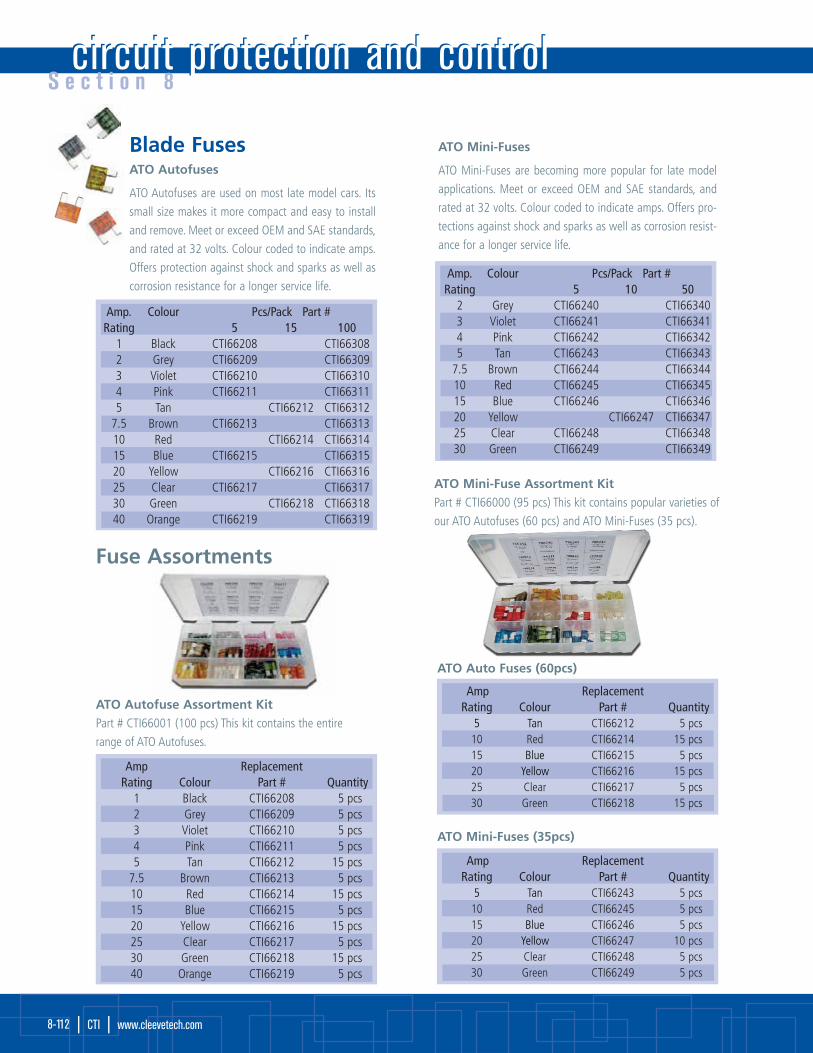
circuit protection and controlcircuit protection and controlS e c t i o n 8
| CTI | www.cleevetech.com 8-112
Blade FusesATO Autofuses
ATO Autofuses are used on most late model cars. Its
small size makes it more compact and easy to install
and remove. Meet or exceed OEM and SAE standards,
and rated at 32 volts. Colour coded to indicate amps.
Offers protection against shock and sparks as well as
corrosion resistance for a longer service life.
ATO Mini-Fuse Assortment Kit Part # CTI66000 (95 pcs) This kit contains popular varieties of
our ATO Autofuses (60 pcs) and ATO Mini-Fuses (35 pcs).
ATO Autofuse Assortment Kit Part # CTI66001 (100 pcs) This kit contains the entire
range of ATO Autofuses.
ATO Mini-Fuses (35pcs)
ATO Auto Fuses (60pcs)
Fuse Assortments
Amp. Colour Pcs/Pack Part # Rating 5 15 100
1 Black CTI66208 CTI663082 Grey CTI66209 CTI663093 Violet CTI66210 CTI663104 Pink CTI66211 CTI663115 Tan CTI66212 CTI66312
7.5 Brown CTI66213 CTI6631310 Red CTI66214 CTI6631415 Blue CTI66215 CTI6631520 Yellow CTI66216 CTI6631625 Clear CTI66217 CTI6631730 Green CTI66218 CTI6631840 Orange CTI66219 CTI66319
ATO Mini-Fuses
ATO Mini-Fuses are becoming more popular for late model
applications. Meet or exceed OEM and SAE standards, and
rated at 32 volts. Colour coded to indicate amps. Offers pro-
tections against shock and sparks as well as corrosion resist-
ance for a longer service life.
Amp. Colour Pcs/Pack Part # Rating 5 10 50
2 Grey CTI66240 CTI663403 Violet CTI66241 CTI663414 Pink CTI66242 CTI663425 Tan CTI66243 CTI66343
7.5 Brown CTI66244 CTI6634410 Red CTI66245 CTI6634515 Blue CTI66246 CTI6634620 Yellow CTI66247 CTI6634725 Clear CTI66248 CTI6634830 Green CTI66249 CTI66349
Amp ReplacementRating Colour Part # Quantity
1 Black CTI66208 5 pcs2 Grey CTI66209 5 pcs3 Violet CTI66210 5 pcs4 Pink CTI66211 5 pcs5 Tan CTI66212 15 pcs
7.5 Brown CTI66213 5 pcs10 Red CTI66214 15 pcs15 Blue CTI66215 5 pcs20 Yellow CTI66216 15 pcs25 Clear CTI66217 5 pcs30 Green CTI66218 15 pcs40 Orange CTI66219 5 pcs
Amp ReplacementRating Colour Part # Quantity
5 Tan CTI66212 5 pcs10 Red CTI66214 15 pcs15 Blue CTI66215 5 pcs20 Yellow CTI66216 15 pcs25 Clear CTI66217 5 pcs30 Green CTI66218 15 pcs
Amp ReplacementRating Colour Part # Quantity
5 Tan CTI66243 5 pcs10 Red CTI66245 5 pcs15 Blue CTI66246 5 pcs20 Yellow CTI66247 10 pcs25 Clear CTI66248 5 pcs30 Green CTI66249 5 pcs

S e c t i o n 8
circuit protection and control | CTI | 8-113
Blade Fuses/Fuse HoldersMaxi-Fuses are used to protect circuits in the wiring harness, usually found under the hood, in a fuse panel or in the supplementary
panel near the battery and are rated at 32 volts.
Maxi-Fuses
Amp. ReplacementRating Colour Part # Quantity Part # Quantity
20 Yellow CTI66250 1 CTI66350 25030 Green CTI66251 1 CTI66351 25040 Orange CTI66252 1 CTI66352 25050 Red CTI66253 1 CTI66353 25060 Blue CTI66254 1 CTI66354 250
Fuse Holders for ‘ATO®/ATC’ Autofuses
Fuse Holders For Maxi/Mini Fuses
Fuse holders can be used with or without a cover. Maxi Fuse holder has 6 ga–6” lead wire and accommodates Maxi fuses from 20 to
60 amps. Mini-Fuse holder has 16 ga-6” lead wire and accommodates Mini-Fuses from 2-20 amps. 10/pack.
ATO Fuse HolderPart #CTI64103 Self-stripping, in-line fuse holder for ATO fuses.
10 pieces/pack (Part #CTI64103C for 100 pack).
Fuse Holders
Provides the most efficient method for full protection of
all electrical equipment. 16 ga. 2–4-1/4” (114 mm)
leads. Fuse holders accommodate all Autofuses from 3
through 20 amps. 25/pack.
Cover sold separately.
Amp Part #7.5 CTI6412710 CTI6412920 CTI6413130 CTI64126*
Cover CTI66259*12 ga. lead
Part # CTI67255
Maxi Fuse holder only.Supplied without fuse.
Part # CTI67256
Maxi Fuse holder only.
Part # CTI67257
Maxi Fuse holder only.Supplied without fuse.
Part # CTI67258
Maxi Fuse holder only.

circuit protection and controlcircuit protection and controlS e c t i o n 8
| CTI | www.cleevetech.com 8-114
Glass Fuses & Holders
Glass Fuse BlocksFor SFE-20 amp or 3AGC type fuses, 1/4”(6.4 mm) diameter. x 1-1/4” (31.8 mm)long. Screw terminals with phosphor bronzefuse clips and hard fiber insulator base.
Screw Type Terminal BlocksSelf-insulating molded housing.Tin-plate brass screws and binders.
Blade-Type Fuse BlocksCompact yet rugged, accepts ATO or ATCblade fuses or blade-type automatic ormanual reset circuits breakers.
Universal ‘Plug in’ Circuit Breakers Continuous self-resetting 6-12 volt circuitbreaker. Use with headlight switches, windowmotors, etc. and suitable for replacing fuses inmany other applications. Two #10-32 stud terminals hex nuts and washers.
Fuse Blocks & Terminal Blocks
Glass FusesReplacement glass tube-type fuses fordomestic vehicles. 5/box.
In-Line Fuse HolderSupplied with fuse. 25/box
Panel Fuse Holder
Part # CTI66042Maximum 20 amp rating. Mounts in 1/2” (12.7 mm) diameter hole.
Universal ‘Plug in’ Circuit Breakers Heavy-duty replacements for ATC and ATO blade typefuses. Saves time and money in replacing burned-outfuses. Simply snap off tabs with pliers at desired position for size adjustment.
Application: 12 volt DC electrical systemsDimensions: 0.840” (21.3 mm) x 400” (10.2 mm) x 1.5” (38.1 mm)
SFE Amp Part #9 CTI6618814 CTI6618920 CTI6619030 CTI66191
Colour SFE Amp Part #Red 14 CTI64082
Black 20 CTI64083Ivory 30 CTI64084Ivory 9 CTI64081
Positions Part #6 CTI660438 CTI6604410 CTI66045
Pairs Part #4 CTI621046 CTI6210510 CTI62106
Positions Part #3 CTI660204 CTI660216 CTI660236* CTI62132
*with solid brass bus barfor ‘hot feed’ connecting
Circuit Breakers
Amp Part #15 CTI6601320 CTI6601425 CTI6601530 CTI66016
Amp Part #10 CTI6607015 CTI6607120 CTI6607230 CTI66073

S e c t i o n 8
circuit protection and control | CTI | 8-115
Fuse Block ConnectorsPart # CTICT6100
Fuse Block connectors allow:
• Tapping power for accessories;
• Checking voltage, shorts, opens and
current draw;
• 3 piece kit to fit maxi, ATO and mini size automotive blade fuse block connectors.
Circuit TesterPart # CTI64700
For 6/12/24 volt systems with an unbreakable handle and
a heavy-duty ground clip. Tester contains a 5 ft (1.5 m)
heavy-duty rubber coated lead wire.

tooling and equipmenttooling and equipmentS e c t i o n 9
| CTI | www.cleevetech.com 9-116
Wire & Cable Tools
CR-CTI300: Ratchet tool crimps insulated terminals from #22-10 AWG.
CR-CTI100Crimps insulated & non insulated terminals from #22 to #10 AWG.Includes stripper and bolt cutter.
Cable Stripper
Ideal for stripping a full range of cable
from 8 ga to 4/0 ga
Compact Universal Crimping Tool
Ideal for crimping battery terminals from
8 ga (heavy duty only for 8 ga) to 1/0 ga.
Approximately 16” long.
Compact Cable Cutter
Easily cuts all cable sizes up to
2/0 ga. Approximately 8” long.
Part # CTI95728
Compact Universal Crimping Tool
Part # CTI95714
Cable Cutter
Part # CTI95731
Universal Crimping Tool 8 ga-4/0
Cable Cutter
The long handle provides excellent
leverage for cutting large cable
up to 350 MCM. Approximately
18” long.
Universal Crimping Tool 8GA-4/0
‘Mechanics choice’ for crimping battery terminals
from 8 ga to 4/0 ga. Approximately 25” long.
Part # CTI95721
Cable Striper
Part # CTI95712
Compact Cable Cutter

S e c t i o n 9
tooling and equipment | CTI | 9-117
Heating ToolsElectrical tooling may be available in various voltage ratings.120 volt AC is standard (for part numbers shown) and will be supplied unless specified otherwise.
TFX-3000 Two Stage General Purpose Hot Air Gun
• Rugged molded construction
• 400˚C/590˚C (750˚F/1100˚F), 1200 watts
• Shaped to free-stand on end
Includes Free Reflector Tip for TFX-3000
Part # CTIREF-35
TFX2050 Butane Micro Torch
• Electronic instant ignition system
• Adjustable flame
• Efficient, hand-held, free standing design
• Refillable butane fuel tank
• Optional flameless soldering head
• Optional hot blower and reflector
(ideal for use with Thermafix® products).
Specifications:
• Dimensions:155 mm x 90 mm x 35 mm
(Height x Width x Grip diam.)
• Max. temp.:1300˚C (2370˚F)
• Working time: approx. 90 minutes
TFX2050 ‘Special Edition’
Features the RK 2020 &
3 accessory tips in a handy
carrying case.
Butane sold separately.
SH-51Hot Blower Head
SH-41Flameless, HotBlower Head
SH-11Soldering Head
CT-1 Mini Torch
• Compact and economical
for small jobs
• Ships in a variety of colours
(not optional)
• Comes with refillable lighter
or compatible with most disposables
HL 1800 Electronically Monitored Heavy Duty Hot Air Gun
• Stepless settings
• 100˚C-600˚C, 2000 watts (max)
• Shaped to free-stand on end
HG 3002 LCD Electronically MonitoredProfessional Hot Air Gun
• Digital display
• Air volume monitoring
• Cool air stage
• Stage 1 50˚C, Stage 2 50˚C-600˚C, 2000 watts
• Shaped to free-stand on end
SA-51
Reflector
Butane Torch (optional)Accessory Tips
Available separately or in the 3-piece RK-SH3 Kit(SH-11, SA-51 and SH-51)

S e c t i o n 1 0technical data and specificationstechnical data and specifications
| CTI | www.cleevetech.com 10-118
Manufacturing Support ServicesCTI can provide finished and tested products and assemblies to meet specific program orcustomer requirements, or can provide product to meet CTI specifications, such as the harness assembly specification that follows.
CTI can support existing designs, from build to print to suggestions of product improve-ments and cost saving opportunities through to new design supported with samples,drawings and test data.
CTI can offer and support:
• Mechanical engineering, design and manufacturing services;
• Prototype and production manufacturing;
• Mature product design improvement and feasibility studies;
• Cost effective design analysis incorporating design modifications utilizing currentprocesses and procedures to reduce cost and lead times;
• Build to print prototype, pre and full production manufacturing/assembly;
• Concurrent engineering and advanced manufacturing.
CAS–130159A Cable Assembly Specification
1. SCOPE
Cable assembly specification for a single or multi-branched electrical wiring harness for useon a military vehicle.
2. PURPOSE
This specification defines the requirements for the fabrication, inspection, and acceptanceof single or multi-branched electrical wiring harness assemblies for use on military vehicleprojects.
3. APPLICABLE DOCUMENTS
The following documents, of the issue in effect on the date of this specification, form a partof this specification to the extent specified herein.
4. REQUIREMENTS
4.1 General
The wiring harness assemblies shall be defined by the applicable wiring harness draw-
ings in the areas of dimensions, wiring schematics, wire gauge, connector and keyway
orientation, connector adaptor, molded parts, tubing, and other general assembly
requirements. The drawing takes precedence over any conflicts between this specifica-
tion and the respective drawing.
4.2 Materials
4.2.1 Connectors
Connectors shall be selected according to the specific customer requirements.
Attention should be made with respect to reliability, availability, and cost.
4.2.2 Ring and Lug Terminals
Terminals, such as ring or lug, shall be selected to fit the application. All terminals
shall be crimp-style, tin-plated copper unless otherwise specified. Insulated
barrels are preferred.
Product Support
Customer Support
Technical Information

S e c t i o n 1 0
technical data and specifications | CTI | 10-119
4.2.3 Primary wire
Unshielded individual wires shall be selected according to the specific customer requirements and using calculations derived
from MIL-W-5088.
4.2.4 Unshielded twisted pairs
Cables for unshielded twisted pairs or other multiple twisted conductors shall be selected according to the specific customer
requirements.
4.2.5 Shielded wire
Cables for shielded wire and shielded twisted pair wire shall be selected according to the specific project requirements.
4.2.6 Gross shield
Shield material over wire/cable bundle shall be tin-coated copper wire per ANSI C7.4 providing a minimum coverage of 90%
unless otherwise specified.
4.2.7 Outer jacket
Material shall be polychloroprene sleeving per M23053/16 or equivalent, sized as appropriate for the bundle diameter.
4.2.8 Molded parts
Molded parts shall be compatible with the outer jacket or insulation sleeving.
4.2.9 Dual wall sleeving
Insulation sleeving with pre-coated adhesive or dual wall sleeving shall be per MIL-I-23053/4 or equivalent.
4.2.10 Tape and adhesive
4.2.10.1 Heat curable
Heat sealable thermoplastic adhesive shall be used where required if the part to be bonded is not pre-coated. The
adhesive shall have a temperature rating of -55°C to 120°C.
4.2.10.2 Spot tape
Where necessary, spot taping shall be used to hold wire bundles together before application of heat-shrink tubing.
Tape shall be clear Mylar or equivalent. Kapton tape shall not be used. Spot taping shall also be used to protect wire
insulation from shield soldering. Tape shall be 200°C rated glass cloth per MIL-I-19166 or equivalent.
4.2.11 Connector adaptors
Connector adaptors shall be used to terminate overbraid and non-braided cable assemblies. The adaptor provides a mounting
surface for the molded boot and/or the overbraid. The adaptor is to stay locked into location on the connector after
vibration to M85049 and MIL-C-38999. The adaptors are to be of a material and finish that is compatible with the connectors
that they secure to. Cadmium finish is to be minimized with zinc-cobalt the preferred finish where available. Harnesses shall
use straight adaptors as much as possible. Use of 45° and 90° adaptors shall be avoided except where required by limited
space.
4.2.12 Markers
Individual wire markers and cable/harness identification markers shall be yellow polyolefin per MIL-I-23053/5, Class 1 or 3, or
equivalent material. Marking must meet the permanency requirements of MIL-M-81515.
4.2.13 Insulation sleeving
Insulation at connector pins and shield terminations shall be per MIL-1-23053/5, Class 1, 2,or 3 or equivalent.
4.2.14 Solder
Solder shall be Type SN60, SN62, or SN63 per QQ-S-571. Flux used with solid or cored solder shall be noncorrosive Type R or
RFnA per MIL-F-14256.
4.2.15 Splices
Junctions between two or more individual wires shall be joined by splices per MIL-S-83519/1 or equivalent as applicable.
Individual wire shields shall be terminated using splices per MIL-S-83519/2 or MIL-S-83519/1 or equivalent with a separate
wire.

S e c t i o n 1 0technical data and specificationstechnical data and specifications
| CTI | www.cleevetech.com 10-120
4.3 Assembly Details
4.3.1 Workmanship
Assembly procedures shall be per MIL-STD-454, requirement 9.
4.3.2 Branches
All branches shall be shown on the drawing and dimensioned accordingly. Branch dimensions may be shown on each
individual leg as a tag. The dimension tag denotes the entire branch length including the connector. Straight connectors are
dimensioned to the end of the connector. Right angle connectors are dimensioned to the centre of the connector. Ring
terminals are dimensioned to the centre of the terminal.
4.3.3 Transitions and Breakouts
Harness branches shall be made using either a transition or breakout as specified on the drawing. A transition uses a
molded part to separate the branches. A breakout uses a piece of tubing (approximately 50 mm) to separate and seal the
branches. A longer piece of tubing (approximately 75 mm) may be used to cover splices where specified on the drawing. A sin-
gle cable tie per MS3367 shall be used as a strain relief at every breakout. Packing of joints is allowed where necessary to
increase the diameter of the branch.
4.3.4 Tolerances
Unless otherwise specified on the applicable harness drawing, tolerances on length dimensions shall be per the following table.
Tolerances on keyway clocking to connector backshells or boot angles shall be 15° unless otherwise stated on the applicable
drawing.
4.3.5 Soldering
Operations shall be per MIL-STD-454, requirement 5.
4.3.6 Crimping
Crimp type connector contacts and terminal lugs shall be crimped using crimping tools specified per the applicable
specification and procedures defined in MIL-C-22520, or by the connector manufacturer. Terminal lugs shall be end soldered
to seal the exposed end of the conductor. No wicking of solder into the conductor shall be allowed.
4.3.7 Splices
Splices shall only be used when specified on the harness drawing schematic to join two or more individual wires or to
terminate wire shields. Splices shall not be used as a repair method without customer approval. Individual wires shall be
stripped in accordance with MIL-W-5088, Section 3.17.2. Shielding shall be cut short of insulation 0.25 to 0.375 inches. Splices
shall be applied per MIL-S-83519.
4.3.8 Marking
The identification markings shall include conductor identification, termination identification and assembly identification.
4.3.8.1 Conductor marking
Each individual conductor in the assembly shall be identified at both ends except for cables containing a single conduc-
tor or if the conductors are colour coded. The conductor shall be marked with the connector reference designator and
pin number or letter. Example: Connector P1, wire in contact A is marked P1-A.
4.3.8.2 Termination marking
Each major connector termination shall be identified with the assembly part number, reference designation and harness
number unless otherwise specified on the assembly drawing. The marker shall be approximately 50 mm from, or as close
as practical, to the junction between the harness leg and the boot. Each minor connector termination (lug, ring termi-
nal, commercial connector, etc…) shall be identified with the reference designation only.
Length Tolerance
0 to 1000 mm -0, +25 mm
1000 to 3000 mm -0, +50 mm
Over 3000 mm -0, +75 mm

S e c t i o n 1 0
technical data and specifications | CTI | 10-121
4.3.8.3 Assembly marking
The finished assembly shall be identified in accordance with MIL-STD-130. The marking shall include as a minimum, the
design activity CAGE, the part number, and the harness reference designation centrally located on the main branch of
the harness. For multi-branch harnesses, the marker shall be applied to the branch with the largest overall diameter, also
centrally located.
4.3.9 Insulation
Install heat shrinkable tubing over all contacts and exposed bare wire at all connectors. Tubing shall also cover unterminated
or exposed shielding. The sleeving when shrunk, must be snug fitting and provide a non-slip, permanently fixed assembly.
4.3.10 Circular metal connector torque
All threaded backshell parts and any special threaded adaptors at connectors or transitions shall be assembled, then tightened
to the torque specified per the table below unless otherwise specified by the adaptor manufacturer.
4.3.11 Gross shield installation
The shield shall maintain a minimal optical coverage of 90%. Where applicable, the gross shield shall be insulated from all
conductors and wire shielding to avoid damage to the bundle and to meet the requirements of the applicable specification.
Electrical continuity shall be maintained from connector to connector through the adaptors, gross shield, and transitions to
meet requirements of the specification. Attachment method shall be compatible with the adaptor and shall ensure 360°
contact between the gross shield and the adaptor.
4.3.12 Jacketing
The outer jacket shall be installed between all terminating points and transitions. Jacketing shall extend into the boot
or transition a minimum of 25 mm. The joint shall be sealed using adhesive to provide a visible, 360° watertight bond. The
adhesive shall be compatible with the material and have a temperature rating of -55°C to 105°C minimum unless
otherwise specified.
4.3.13 Terminations
4.3.13.1 Military specification terminations
Individual wires shall be stripped per MIL-W-5088, Section 3.17.2. Contacts and terminals shall be applied and installed
in accordance with the drawing schematic. Unused connector contacts shall be installed. Individual sealing plugs shall
not be used unless specified in the drawing. Exposed contacts shall be insulated. Terminal lugs shall be insulated using
dual wall sleeving such that the terminal barrel is completely covered. The sleeving shall also extend and overlap the
outer jacket. Boots shall be bonded to the outer jacket and the connector backshell with adhesive if the boot is not pre-
coated. The adhesive should provide a visible, 360° watertight seal.
4.3.13.2 Commercial/industriaI terminations
Individual wires shall be stripped per the connector manufacturer's specification. Contacts and terminals shall be applied
and installed in accordance with the drawing schematic. Unused connector contacts shall only be installed if required.
Individual sealing plugs shall be used where required. Where required, boots shall be bonded to the outer jacket and the
connector backshell with adhesive if the boot is not pre-coated. The adhesive should provide a visible, 36O° watertight
seal. Where no boots are used, individual wire slack shall be 10 to 20 mm for less than 10 circuits and 30 to 35 mm for
greater than 11 circuits.
4.4 Electrical Performance
The finished harness assembly shall be capable of meeting the following tests.
4.4.1 Insulation resistance
100 megaohms minimum measured between each conductor, the gross shield, and connectors per MIL-STD-202, Method 302,
Test condition B, with 1.0 second minimum electrification time, 500 ± 50 VDC test voltage.
4.4.2 Circuit resistance
500 milliohms maximum measured pin-to-pin through each conductor and 1.5 ohms maximum measured through the gross
shield between each connector shell per MIL-STD-202, Method 303.

S e c t i o n 1 0technical data and specificationstechnical data and specifications
| CTI | www.cleevetech.com 10-122
4.5 Mechanical Performance
4.5.1 Appearance
The harness shall be free of mechanical imperfections such as nicks, cuts or abrasion marks along its entire length. Plating on
connectors and adaptors shall be free of scratches, pitting, or marring that would otherwise degrade the environmental per-
formance. Pins and terminal lugs shall not be bent.
4.6 Environmental
The finished harness assembly shall be capable of meeting the following conditions.
4.6.1 Temperature range
With connectors mated, shall be capable of operating over a temperature range of -40°C and 100% RH to 44°C and 14% to
44% RH. The storage temperature shall be -40°C to 63°C.
4.6.2 Fluid resistance
No degradation by exposure to diesel fuel per VV-F-800 and MIL-F-16884, brake fluid per MIL-B-48176, hydraulic fluid per
MIL-H-5606 and engine oil per MIL-L-2104 and MIL-L-46167.
4.6.3 Moisture resistance
With connectors mated or plugged, shall be subjected to the spraytight test per MIL-STD-108, paragraph 4.10.
5. QUALITY ASSURANCE PROVISIONS
5.1 Responsibility for inspection
CTI will be responsible for the performance of all inspection requirements. CTI may use our own or any other facilities
suitable for the performance of the inspection requirements. The customer or their agents reserves the right to perform any of the
inspections set forth in this specification.
5.1.1 Test equipment and inspection facilities
Test and measuring equipment and inspection facilities of sufficient accuracy, quality, and quantity to permit performance of
the required inspection shall be established and maintained by CTI. The establishment and maintenance of a calibration sys-
tem to control the accuracy of the measuring equipment shall be in accordance with recognized quality standards.
5.2 Classification of inspection
The inspection of harness and cable assemblies shall be classified as follows:
• First article inspection;
• Quality conformance inspection.
5.3 First article inspection
Unless otherwise specified, CTI shall perform first article inspection after award of contract and prior to serial production. First arti-
cle inspection shall be performed on wiring harness assemblies or cable assemblies that have been produced with production equip-
ment and procedures.
5.3.1 Sample size
First article inspection shall be performed on the first item of each new part number of each wiring harness or cable assembly
in the purchase order. Inspection by similarity is allowed with prior approval from the procuring activity.
5.3.2 First article failure
Failure of the first unit to pass any examination or test may cause refusal to grant first article approval. The customer may refuse
acceptance of production assemblies until corrective action is provided.
5.3.3 Sample disposition
First article samples are deliverable as the first unit of production provided they are not damaged by the first article inspection.
5.3.4 First article inspection tests
First article inspection tests shall be conducted as follows in the order listed.
5.3.4.1 Materials inspection
Material certifications shall be examined for conformance to the requirements of the customer cable specification.
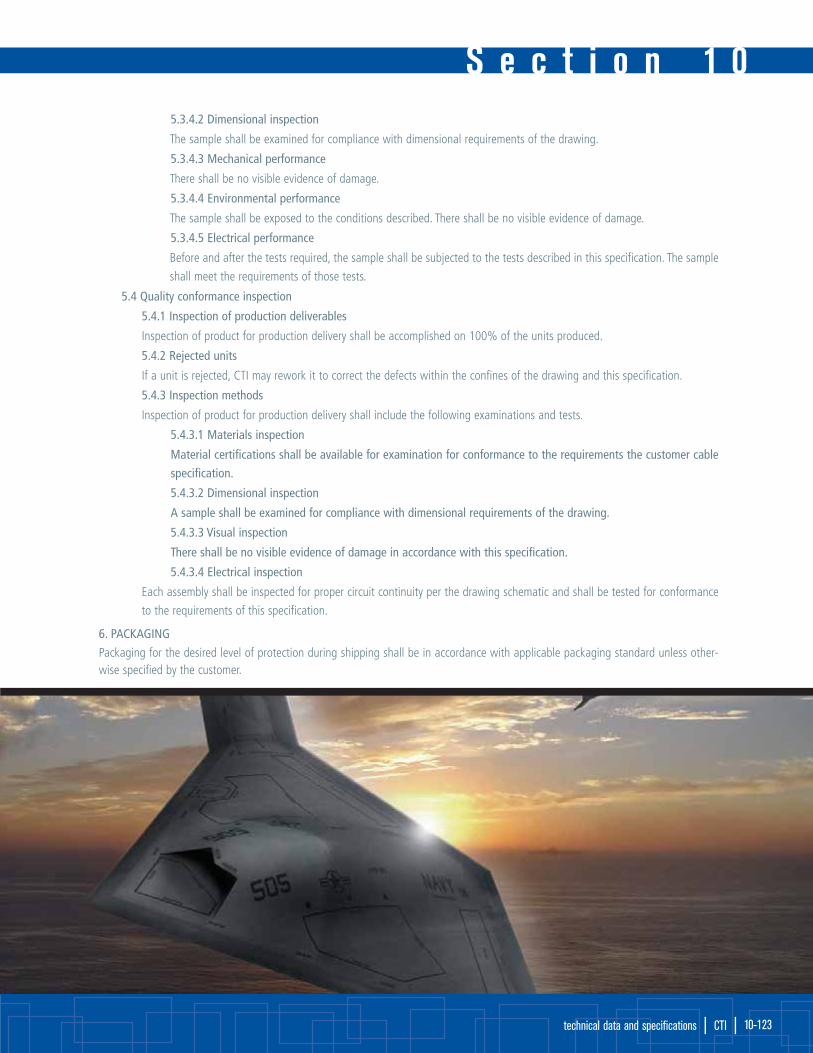
S e c t i o n 1 0
technical data and specifications | CTI | 10-123
5.3.4.2 Dimensional inspection
The sample shall be examined for compliance with dimensional requirements of the drawing.
5.3.4.3 Mechanical performance
There shall be no visible evidence of damage.
5.3.4.4 Environmental performance
The sample shall be exposed to the conditions described. There shall be no visible evidence of damage.
5.3.4.5 Electrical performance
Before and after the tests required, the sample shall be subjected to the tests described in this specification. The sample
shall meet the requirements of those tests.
5.4 Quality conformance inspection
5.4.1 Inspection of production deliverables
Inspection of product for production delivery shall be accomplished on 100% of the units produced.
5.4.2 Rejected units
If a unit is rejected, CTI may rework it to correct the defects within the confines of the drawing and this specification.
5.4.3 Inspection methods
Inspection of product for production delivery shall include the following examinations and tests.
5.4.3.1 Materials inspection
Material certifications shall be available for examination for conformance to the requirements the customer cable
specification.
5.4.3.2 Dimensional inspection
A sample shall be examined for compliance with dimensional requirements of the drawing.
5.4.3.3 Visual inspection
There shall be no visible evidence of damage in accordance with this specification.
5.4.3.4 Electrical inspection
Each assembly shall be inspected for proper circuit continuity per the drawing schematic and shall be tested for conformance
to the requirements of this specification.
6. PACKAGING
Packaging for the desired level of protection during shipping shall be in accordance with applicable packaging standard unless other-wise specified by the customer.

S e c t i o n 1 0technical data and specificationstechnical data and specifications
| CTI | www.cleevetech.com 10-124
Multi-Conductor Cable Colour Chart ReferenceNo. Base 1st 2nd 3rd No. Base 1st 2nd 3rd
Colour Stripe Stripe Stripe Colour Stripe Stripe Stripe1 Black 51 White Blue Violet2 Red 52 White Brown Black3 White 53 White Brown Red4 Green 54 White Brown Green5 Orange 55 White Brown Blue6 Blue 56 White Brown Brown7 Brown 57 White Brown Violet8 Yellow 58 White Violet Red9 Violet 59 White Violet Green10 Gray 60 White Violet Blue11 Pink 61 White Black Red Green12 Tan 62 White Black Red Yellow13 Red Green 63 White Black Red Blue14 Red Yellow 64 White Black Red Brown15 Red Black 65 White Black Red Orange16 White Black 66 White Black Red Gray17 White Red 67 White Black Red Violet18 White Green 68 White Black Green Yellow19 White Yellow 69 White Black Green Blue20 White Blue 70 White Black Green Brown21 White Brown 71 White Black Green Orange22 White Orange 72 White Black Green Gray23 White Gray 73 White Black Green Violet24 White Violet 74 White Black Yellow Blue25 White Black Red 75 White Black Yellow Brown26 White Black Green 76 White Black Yellow Orange27 White Black Yellow 77 White Black Yellow Gray28 White Black Blue 78 White Black Yellow Violet29 White Black Brown 79 White Black Blue Brown30 White Black Orange 80 White Black Blue Orange31 White Black Gray 81 White Black Blue Gray32 White Black Violet 82 White Black Blue Violet33 White Black Black 83 White Black Brown Orange34 White Red Black 84 White Black Brown Gray 35 White Red Red 85 White Black Brown Violet36 White Red Green 86 White Black Orange Gray37 White Red Blue 87 White Black Orange Violet38 White Red Brown 88 White Black Gray Violet39 White Red Violet 89 White Red Black Green40 White Green Black 90 White Red Black Yellow41 White Green Red 91 White Red Black Blue42 White Green Green 92 White Red Black Brown43 White Green Blue 93 White Red Black Orange44 White Green Brown 94 White Red Black Gray45 White Green Violet 95 White Red Black Violet46 White Blue Black 96 White Red Green Yellow47 White Blue Red 97 White Red Green Blue48 White Blue Green 98 White Red Green Brown49 White Blue Blue 99 White Red Green Orange50 White Blue Brown 100 White Red Green Gray

Wire Specification Reference ChartCircular Coated Copper High Strength
Mil Ohms/1000 ft High StrengthAWG Strands OD Area Nickel Break Ohms/ Break
(CMA) Tinned Plated Strength (lbs) 1000 ft Strength (lbs)32 7/40 0.0093 67.3 157.0 165.0 1.8 176.0 3.430 7/38 0.012 112.0 95.4 97.4 3.0 107.0 5.628 7/36 0.015 175.0 60.9 61.9 4.7 68.5 8.426 7/34 0.019 278.0 38.2 38.7 7.0 43.2 14.026 19/38 0.020 304.0 35.3 36.1 8.2 39.6 15.224 7/32 0.024 441.0 23.7 23.9 11.9 25.8 21.724 19/36 0.025 475.0 22.5 22.9 12.7 25.4 22.822 19/34 0.032 754.0 14.2 14.3 19.0 16.0 38.020 19/32 0.040 1216.0 8.76 8.85 32.0 9.5 58.918 19/30 0.050 1900.0 5.60 5.64 51.0 - -16 19/29 0.057 2426.0 4.38 4.41 65.0 - -14 19/27 0.070 3830.0 2.77 2.79 103.0 - -12 19/25 0.090 5088.0 1.74 1.75 153.0 - -12 37/28 0.088 5874.0 1.81 1.83 155.0 - -10 37/26 0.111 9354.0 1.14 1.14 250.0 - -8 133/29 0.169 16983.0 0.634 0.663 450.0 - -6 133/27 0.213 26918.0 0.401 0.425 720.0 - -4 133/25 0.255 42615.0 0.252 0.263 1140.0 - -
S e c t i o n 1 0
technical data and specifications | CTI | 10-125

Unit Conversion Chart ReferenceUnit X Constant =Unit Unit X Constant =Unit
Btu 778.0 Foot-pound (ft-lb) Horsepower (hp) 33000.0 Ft-lb/min
Btu 1054.8 Joules Horsepower (hp) 550.0 Ft-lb/sec
Btu 0.293 Watt-hours (w-hr) Horsepower (hp) 745.7 Watts (w)
Centimeters (cm) 0.032808 Feet (ft) Inch (in) 0.027178 Yards (yd)
Centimeters (cm) 0.3937 Inches (in) Inch (in) 0.083333 Feet (ft)
Centimeters (cm) 0.00001 Kilometers (km) Inch (in) 0.0000254 Kilometers (km)
Centimeters (cm) 0.010 Meters (m) Inch (in) 0.0254 Meters (m)
Centimeters (cm) 10.0 Millimeters (mm) Inch (in) 2.54000514 Centimeters (cm)
Circular mils 0.00064516 Circular millimeters Inch (in) 25.4000514 Millimeters (mm)
Circular mils 0.0000007854 Inches2 (in2) Inch (in) 1000.0 Mils
Circular mils 0.00050671 Square Millimeters (mm2) Joules 0.000948 Btu
Circular mils 0.7854 Mils2 Joules 107 Ergs
Circular mils 0.7854 Square mile Kilogram 2.205 Pound
Cubic Centimeter (cm3) 0.000035314 Cubic foot (ft3) Kilogram/km 0.6214 Pound/kft
Cubic Centimeter (cm3) 0.061023 Cubic inch (in3) Kilometers 0.6214 Miles
Cubic Centimeter (cm3) 0.000001 Cubic meter (m3) Liters (L) 61.025 Cubic inch (in3)
Cubic Centimeter (cm3) 0.00026417 Gallons Meters (m) 1.093611 Yards (yd)
Cubic Foot (ft3) 1728.0 Cubic inch (in3) Meters (m) 3.2808333 Feet (ft)
Cubic Foot (ft3) 28317.016 Cubic centimeter (cm3) Meters (m) 39.37 Inch (in)
Cubic Foot (ft3) 0.02832 Cubic meter Meters (m) 100.0 Centimeters (cm)
Cubic Inch (in3) 0.0005787 Cubic foot (ft3) Miles 1760.0 Yards (yd)
Cubic Inch (in3) 0.000016387 Cubic meter (m3) Miles 5280.0 Feet (ft)
Cubic Inch (in3) 16.387162 Cubic centimeter (cm3) Miles 1.6093 Kilometers (km)
Cubic Meter (m3) 1000000.0 Centimeter (cm) Millimeters (mm) 0.0032808 Feet (ft)
Cubic Meter (m3) 35.314456 Cubic foot (ft3) Millimeters (mm) 0.3937 Inch (in)
Cubic Meter (m3) 264.17 Gallons Millimeters (mm) 0.001 Meters (m)
Feet (ft) 0.00018939 Miles Millimeters (mm) 0.01 Centimeters (cm)
Feet (ft) 0.33333 Yards (yd) Millimeters (mm) 39.3701 Mils
Feet (ft) 12 Inches (in) Millimeters (mm) 1000 Microns
Feet (ft) 0.0003048 Kilometer (km) Ohms/kh 0.3048 Ohms/kft
Feet (ft) 0.3048 Meters (m) Ounce 28.35 Gram
Feet (ft) 30.48 Centimeter (cm) Pound 0.4536 Kilogram
Feet (ft) 304.8 Millimeters (mm) Pound/kft 1.4881 Kilogram/km
Feet/Pound (ft/lb) 0.00067197 Meters/grams (m/g) Square Inch 6.452 Square centimeter
Feet/Pound (ft/lb) 0.001285 Btu Square Centimeter 0.155 Square inch
Feet/Pound (ft/lb) 1.356 Joules Square Foot 0.0929 Square meter
Feet/Pound (ft/lb) 0.1383 Kilogram/meter (kg/m) Square Meter 10.76 Square foot
Gallons 3.785332 Liters (l) Square Miles 2.59 Square kilometer
Gallons 0.13368 Cubic foot (ft3) Square Kilometer 0.3861 Square mile
Gallons 231.0 Cubic inch (in3) Watts (w) 44.25 Ft-lb/minute
Gallons 3785.332 Cubic centimeter (cm3) Watts (w) 0.737562 Ft-lb/sec
Grams (g) 15.432 Grains Watts (w) 0.001341 Horsepower (hp)
Gram 0.03527 Ounce Watt-hour (w-hr) 3.41266 Btu
Gram/Centimeter3 0.0361275 Pounds/in3 (lb/in3)
S e c t i o n 1 0technical data and specificationstechnical data and specifications
| CTI | www.cleevetech.com 10-126
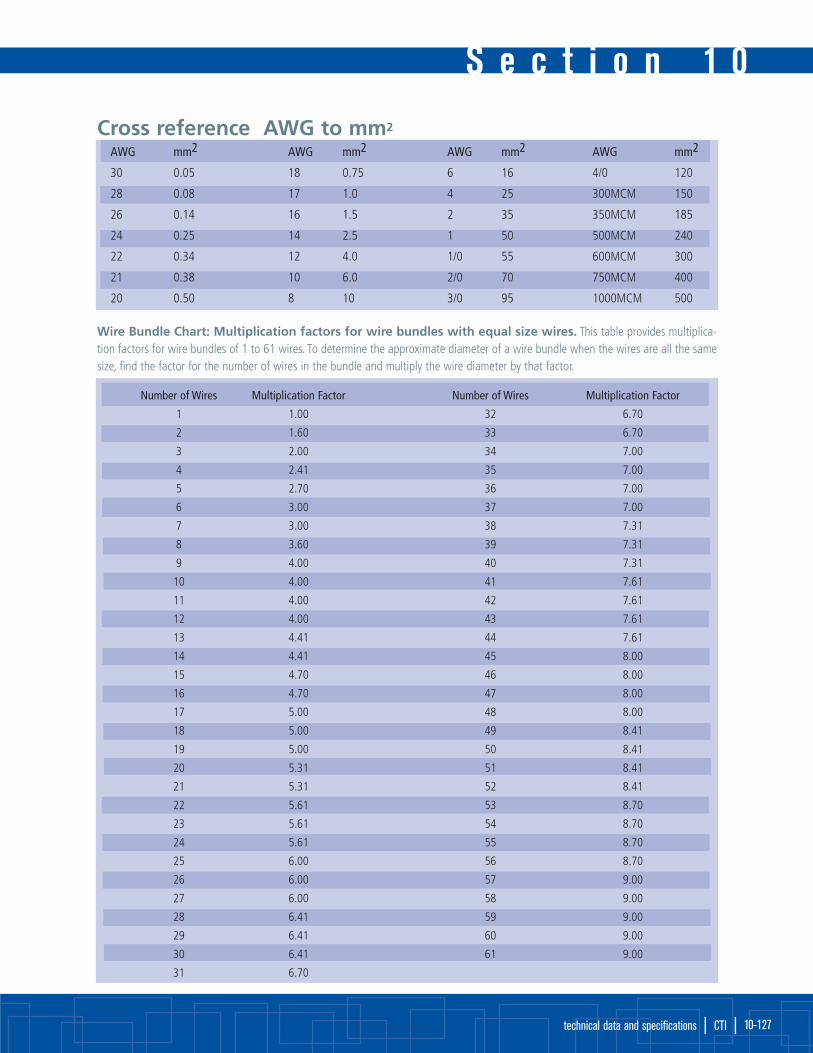
S e c t i o n 1 0
technical data and specifications | CTI | 10-127
Cross reference AWG to mm2
AWG mm2 AWG mm2 AWG mm2 AWG mm2
30 0.05 18 0.75 6 16 4/0 120
28 0.08 17 1.0 4 25 300MCM 150
26 0.14 16 1.5 2 35 350MCM 185
24 0.25 14 2.5 1 50 500MCM 240
22 0.34 12 4.0 1/0 55 600MCM 300
21 0.38 10 6.0 2/0 70 750MCM 400
20 0.50 8 10 3/0 95 1000MCM 500
Wire Bundle Chart: Multiplication factors for wire bundles with equal size wires. This table provides multiplica-tion factors for wire bundles of 1 to 61 wires. To determine the approximate diameter of a wire bundle when the wires are all the samesize, find the factor for the number of wires in the bundle and multiply the wire diameter by that factor.
Number of Wires Multiplication Factor Number of Wires Multiplication Factor
1 1.00 32 6.70
2 1.60 33 6.70
3 2.00 34 7.00
4 2.41 35 7.00
5 2.70 36 7.00
6 3.00 37 7.00
7 3.00 38 7.31
8 3.60 39 7.31
9 4.00 40 7.31
10 4.00 41 7.61
11 4.00 42 7.61
12 4.00 43 7.61
13 4.41 44 7.61
14 4.41 45 8.00
15 4.70 46 8.00
16 4.70 47 8.00
17 5.00 48 8.00
18 5.00 49 8.41
19 5.00 50 8.41
20 5.31 51 8.41
21 5.31 52 8.41
22 5.61 53 8.70
23 5.61 54 8.70
24 5.61 55 8.70
25 6.00 56 8.70
26 6.00 57 9.00
27 6.00 58 9.00
28 6.41 59 9.00
29 6.41 60 9.00
30 6.41 61 9.00
31 6.70

S e c t i o n 1 0technical data and specificationstechnical data and specifications
| CTI | www.cleevetech.com 10-128
Take the universal time (GMT) from London, Englandand add the following to determine your time:
Time Zone Standard Time Daylight Saving Time
International Date Line East (IDLE) +12 hours
New Zealand Standard Time (NZST) +12 hours
New Zealand Time (NZT) +10 hours
Guam Standard Time (GST) +10 hours
Australian Eastern Standard Time (AEST) (AEDT) +10 hours +11 hours
Australian Central Standard Time (ACST) (ACDT) +9.5 hours +10.5 hours
Japan Standard Time (JST) +9 hours
China Coast Time (CCT) +8 hours
Australian Western Standard Time (AWST) +8 hours
India Standard Time (IST) +5.5 hours
Russian Zone 3 +4 hours
Baghdad Time (BT) +3 hours
Russian Zone 2 +3 hours
Moscow Time(MSK) (MSD) +3 hours +4 hours
Eastern European Time (EET) (EEST) +2 hours +3 hours
Russian Zone 1 +2 hours
Central Europe Summer Time (CEST) +2 hours
Central European Time (CET) +1 hour
Middle European Time (MET) +1 hour
Swedish Winter Time (SWT) 0 hours
Greenwich Mean Time (GMT) 0 hours
Universal Time (UT) 0 hours
Western European Time (WET) (WEST) 0 hours +1 hour
British Summer Time (BST) +1 hour
Irish Summer Time (IST) +1 hour
West African Time (WAT) -1 hour
Newfoundland Standard Time (NST) (NDT) -3.5 hours -2.5 hours
Atlantic Standard Time (AST) (ADT) -4 hours -3 hours
Eastern Standard Time (EST) (EDT) -5 hours -4 hours
Central Standard Time (CST) (CDT) -6 hours -5 hours
Mountain Standard Time (MST) (MDT) -7 hours -6 hours
Pacific Standard Time (PST) (PDT) -8 hours -7 hours
Alaskan Standard Time (AKST) (AKDT ) -9 hours -8 hours
Hawaiian Standard Time (HST) -10 hours
International Date Line West (IDLW) -12 hours

s o l u t i o n s @ c l e e v e t e c h . c o m
Although all information in this catalogue, including illustrations, is believed to be reliable, Cleeve Technology International, and all its subsidiary companies, makes no warranties as to the accuracy or completeness of the information, and disclaims any liability regarding the use of the information contained herein.
Users are responsible to independently evaluate the suitability of the product for their application. Cleeve Technology International’s only obligations are those in the Standard Terms and Conditions of Sale forthese products and in no circumstances will the company, and all its subsidiary companies, be liable for any incidental, indirect or consequential damages arising from the sale, resale, use or misuse of the products.
Specifications are subject to change without notice. In addition, Cleeve Technology International reserves the right to make changes in materials or processing without notice to the purchaser which do not affectcompliance with any applicable specification.
The following are trademarks of E.I. du Pont de Nemours and Company: Mylar, Viton.
The following is a trademark of Elf Atochem North America Inc.: Kynar
Cleeve Technology Incorporated
716 Colonel Sam Drive
Oshawa, Ontario,
L1H 7Y2
Canada
Tel: 001-905-579-9502
Fax: 001-905-579-9991
Cleeve Technology GmbH
Masurenweg 11
65817 Eppstein,
Germany
Tel: +49 (0) 6198-587970
Fax: +49 (0) 6198-587971
Cleeve Technology Limited
Unit 2 Leopold Street
Lamberhead Industrial Estate
Pemberton, Wigan,
WN5 8EG,
England
Tel: +44 (0) 1942 217721
Fax: +44 (0) 1942 217717
Cleeve Technology Limited
Unit 12 Twigworth Court
Business Center
Twigworth, Gloucestershire,
GL2 9PG,
England
Tel: +44 (0) 1452-731118
Fax: +44 (0) 1452-731128
Cleeve Technology Pty Ltd.
Eastpint
23/42-46 Wattle Road
Brookvale NSW 2100
Austrailia
Tel: +61 (0)2 9939 6392
Fax: +61 (0)2 9939 6246