an enhanced sliding mode speed control for induction motor
TRANSCRIPT
actuators
Article
An Enhanced Sliding Mode Speed Control for InductionMotor Drives
Fahimeh Shiravani 1,* , Patxi Alkorta 1 , Jose Antonio Cortajarena 1 and Oscar Barambones 2,*
Citation: Shiravani, F.; Alkorta, P.;
Cortajarena, J.A.; Barambones, O. An
Enhanced Sliding Mode Speed
Control for Induction Motor Drives.
Actuators 2022, 11, 18. https://
doi.org/10.3390/act11010018
Academic Editor: Shuxiang Dong
Received: 9 December 2021
Accepted: 3 January 2022
Published: 10 January 2022
Publisher’s Note: MDPI stays neutral
with regard to jurisdictional claims in
published maps and institutional affil-
iations.
Copyright: © 2022 by the authors.
Licensee MDPI, Basel, Switzerland.
This article is an open access article
distributed under the terms and
conditions of the Creative Commons
Attribution (CC BY) license (https://
creativecommons.org/licenses/by/
4.0/).
1 Engineering School of Gipuzkoa, University of the Basque Country, Otaola Hirib. 29, 20600 Eibar, Spain;[email protected] (P.A.); [email protected] (J.A.C.)
2 Engineering School of Vitoria, University of the Basque Country, Nieves Cano 12, 01006 Vitoria, Spain* Correspondence: [email protected] (F.S.); [email protected] (O.B.)
Abstract: In this paper, an enhanced Integral Sliding Mode Control (ISMC) for mechanical speedof an Induction Motor (IM) is presented and experimentally validated. The design of the proposedcontroller has been done in the d-q synchronous reference frame and indirect Field Oriented Control(FOC). Global asymptotic speed tracking in the presence of model uncertainties and load torquevariations has been guaranteed by using an enhanced ISMC surface. Moreover, this controllerprovides a faster speed convergence rate compared to the conventional ISMC and the ProportionalIntegral methods, and it eliminates the steady-state error. Furthermore, the chattering phenomenonis reduced by using a switching sigmoid function. The stability of the proposed controller underparameter uncertainties and load disturbances has been provided by using the Lyapunov stabilitytheory. Finally, the performance of this control method is verified through numerical simulations andexperimental tests, getting fast dynamics and good robustness for IM drives.
Keywords: experimental validation; Induction Motor; Integral Sliding Mode Control; robustness;speed control
1. Introduction
Three-phase machines, such as motors and generators, are used extensively in in-dustry and in civil engineering. Renewable energy sources, machine tools, servo drives,and robots are just a few examples. Because of its low cost, minimal maintenance, lowmoment of inertia, robust architecture, and operational reliability, IM has become widelyemployed in various applications as power electronics technology has advanced. In thelast two decades, the FOC technique has been the most widely used method for regulatingIM in high-performance applications, such as speed and position control of three-phasemotors. The torque and flux control current commands for the IM are decoupled by usingthe FOC method. As a result, the machine is controlled as if it were an independent DCmachine. However, uncertainties such as unexpected parameter variations, external loaddisturbances, and nonlinear dynamics continue to impact the IM’s control performance.The Proportional Integral (PI) regulator, due to its simplicity, clear functionality, and effec-tiveness, is one of the most popular control techniques which has been used in electricalmachines [1]. Nonetheless, because the IM is a nonlinear framework, a well-designednonlinear regulator can improve action in the presence of disturbances and uncertainty [2].Many authors have taken use of different advanced control approaches to govern thepower electronics and drives area in this regard. For instance, adaptive control method [3],Backstepping algorithm [4,5], predictive control method [6] and Sliding Mode Control(SMC) [7–9]. Among the nonlinear control method, the SMC technique has become a fasci-nating nonlinear control method with a particular dynamic performance for IM, such asstrong robustness, quick response, and simple software and hardware implementation [10].
Almost ever since sliding mode ideas imply, the considerable noise which some ofthe sliding mode controllers expose is not pleasant for control engineers and sometimes
Actuators 2022, 11, 18. https://doi.org/10.3390/act11010018 https://www.mdpi.com/journal/actuators
Actuators 2022, 11, 18 2 of 14
has led to resentments and even rejection of the technique. The phenomenon is bestknown as chattering. Chattering is a high-frequency oscillation around the equilibriumpoint, which arises because of the discontinuous nature of the control action. Due tothis, the well-designed control action stands unsuitable for many practical applications.This behavior creates a problem of wear and tear within the mechanical parts, vibrationswithin the machines, or flapping of wing vanes in aerospace and hitting effect. Hence, itis unwanted in light of implementation [11]. Regarding chattering suppression, varioustypes of chattering prevention schemes have been suggested [12–14]. For instance, manyauthors have been designing regulators for IM based on combining SMC theory and otheradvanced control methods such as backstepping algorithm, adaptive method, and fuzzytechnique [15–17]. It should be noted that using SMC by employing other sorts of nonlinearcontrol strategies increments the controller complexity and computational endeavors,which is incompatible with the ease of SMC. Another solution could be applying higherorder sliding mode control to IM. For instance, in [18], authors have taken advantage of thesuper-twisting sliding mode method to eliminate the chattering phenomenon. Furthermore,discrete-time sliding mode control has been applied to the machine in this regard [19,20].
Another way to reduce the chattering phenomenon is to apply some changes to thetraditional sliding surface, which is basically based on error and its derivative signal [21].In [21–24], an integral sliding surface has been applied to the IM to eliminate steady-stateerror, which has been named ISMC. A sensorless adaptive ISMC for IM has been discussedin [21]. In [22], a speed estimator based on the ISMC method for IM has been designedwhere stator current controllers consist of a PI and an ISMC controller, which means morecomplexity. Besides, this speed estimator is not universal and can only be implemented inconjunction with the above current controller. Furthermore, the authors in [23] designedan ISMC anti-windup in the speed control loop of the IM. Furthermore, an ISMC methodhas been proposed in [24] to start the sensorless IM in the rotating condition.
In this paper, the considered IM is under load torque and it is perturbed by modeluncertainties. The common objective in nearly all industrial control design procedures is toprovide a fast and accurate response by employing a smooth and effective electromagnetictorque. This goal will be achieved by designing an efficient control law. The idea is toregulate the mechanical rotor speed of IM by using ISMC method to achieve asymptoticspeed tracking and disturbance rejection. In the controller design process, the FOC theoryhas been applied to get fast dynamic performance. Furthermore, to tackle the chatteringproblem and to eliminate the steady-state error, the proposed robust controller is designedbased on the ISMC while using a continuous switching function arctan(). Besides, the pro-posed controller has a faster speed convergence rate compared to the conventional ISMCmethod, due to the surface design difference. Compared with the conventional ISMC,in this paper, the arctan() function of the error of the mechanical speed has been consideredin the surface design. By employing this function, the control action becomes smoother andprovides a faster dynamics. Additionally, the presented proposal offers good robustnessunder parametric uncertainties. Then, by using a Lyapunov-based approach, robust outputtracking of rotor speed is achieved. Since most of the electric drives in the industry arecontrolled by PI regulators, this proposal also has been compared with the PI controller todemonstrate the ability of the proposed controller in fast convergence of the speed of theIM. Furthermore, worth noting that, in this work, the experiments have been done by useof a 7.5 kW commercial IM, which shows the applicability of the projected methodologyfor the real applications within the industry.
The paper has been organized as follows: the speed controller of IM is designed inSection 2. In Section 3, the experiment platform and the effectiveness of the proposedcontroller by employing several simulations and experimental tests are shown. Finally,in Section 4, the conclusion has been presented.
Actuators 2022, 11, 18 3 of 14
2. Robust Speed ISMC Design2.1. Model of the Mechanical Loop of IM
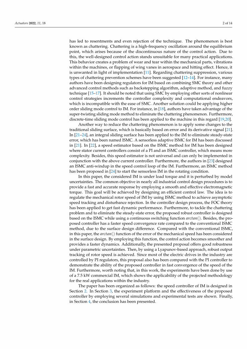
The block diagram of the proposed control scheme is shown in Figure 1. In this figureby starting from the right side of this block set, by measuring the three stator phase currents,and by using the Clarke’s and Park’s transformations (ABC→ dq block), the isd and isqcomponents in the rotational reference frame are obtained. The resulting transformedcurrents isd and isq will be responsible for magnetizing rotor flux and electromagnetictorque, respectively. The block Calc θs calculates the rotor flux angle, θs , by using theindirect FOC control technique. The speed error between the reference and real speedis fed to the ISMCωm block (speed regulator). The output of the block will be i∗sq, whichis responsible for the electromagnetic torque reference generation. Torque and flux cur-rents are also controlled by the mean of the two PIisd and PIisq current regulators, whichare providing the correspondent v∗sd and v∗sq voltage references in the rotating referenceframe. They are transformed to the stationary reference frame by using the inverse parktransformation block (dq→ αβ block), giving v∗α and v∗β voltage references. These twovoltages are applied to the modulator Space Vector Pulse Width Modulation (SVPWM),which transforms stationary reference frame voltages to control signals (pulses) to drivethe power three-phase inverter IGBTs.
Figure 1. Block diagram of IM.
ISMC speed controller is designed in the d-q synchronous reference frame by using theindirect FOC, where it is assumed that ψrq = 0 and consequently ψr = ψrd. Thus, the equa-tion of the inductions electromagnetic torque of the motor has the following expression,
Te =3pLm
4Lrψrisq = KTisq (1)
where KT is the torque constant:
KT =3pLm
4Lrψir (2)
Taking the mechanical equation:
Jωm + Bvωm + TL = Te (3)
it can be written as:
ωm + aωωm + fω = bωisq (4)
where the following parameters can be defined as: aω = Bv/J, bω = KT/J, fω = TL/J
Actuators 2022, 11, 18 4 of 14
2.2. Basic Principles of ISMC
There are two phases to the ISMC regulator’s design. The first step is to choose theadequate integral sliding surface to meet the control goals. The second step is to design thecontrol law, which ensures that the system’s trajectories reach and remain on the slidingsurfaces in a finite amount of time (reaching phase). In this approach, the ISMC projectmay be categorized into two sections: defining an appropriate sliding surface S(x) anddeveloping a control law. To reach the sliding regime, the conventional ISMC requires anerror as well as its integral signal [25].
S(x) = (µ f + d/dt)r−1∫
edτ (5)
where e = (x∗ − x) is the error, x is the system state space, x∗ is system state spacereference, r is the degree of the sliding mode, and µ f is the weighting factor. The slidingmode control was used to assess the generic system (6) in [23], and the design process wasthoroughly described.
x = f (x) + g(x)Uc
y = h(x) (6)
where x ∈ Rn is the state space vector, Uc ∈ Rm is the input control action, and y(t) ∈ Rp
is the system output. Uc can be obtained by using equivalent control method [23]:
UC = Uequ + Un (7)
where Uequ is the equivalent control action that ensures the system’s convergence. It iscalculated off-line with the use of a model that precisely represents the plant. Furthermore,Un is a switching control action that assures the attractiveness of the surface in the systemstate space.
Un = βsgn(S(x)) (8)
The positive gain β in the above equation will be designed to ensure the Lyapunov stabil-ity criterion.
2.3. Conventional ISMC for IM (D1 Design)
To continue, the mechanical (4) is considered under parameter uncertainty terms ofthe aω, fω and bω as (∆aω, ∆ fω, ∆bω),
ωm = −(aω + ∆ω)ωm − ( fω + ∆ fω) + (bω + ∆bω)isq (9)
now the speed tracking error is defined as:
eω = ωm −ω∗m (10)
which ω∗m is the mechanical rotor speed reference, and by taking its derivative:
eω = ωm − ω∗m = −aωeω + uω + dω (11)
where the control law is defined as:
uω = −aωω∗m + bωisq − fω − ω∗m (12)
and compiling the uncertainty terms in dω term, the following expression is obtained:
dω = −∆aωωm − ∆ fω + ∆bωisq (13)

Actuators 2022, 11, 18 5 of 14
Now the sliding variable sω(t) is defined with an integral component as:
sω = eω +∫ t
0Kωeωdt (14)
The following assumptions are formulated in order to obtain speed tracking: (A1) Theconstant Kω should be chosen such that Kω > 0 for all time. The law uω should be designedin a way that guarantees convergence to the sliding surface in a finite time. Therefore:
uω = aωeω − Kωeω − βωsign(sω) (15)
(A2) The gain βω must be chosen so that |dω | < βω, for all times.Finally, the torque current reference, i∗sq , is obtained directly by substituting (15)
in (12),
i∗sq = 1/b(aωeω − Kωeω − βωsign(sω) + aωω∗m + fω + ω∗m) (16)
Theorem 1. According to (1), the torque current command (16) will control the Te. Consequently,based on (3), the rotor speed will be regulated so that speed tracking error (10) tends to zeroasymptotically, as the time tends to infinity.
Proof. Taking the derivatives of sliding surface sω gives,
sω = eω + d/dt∫ t
0Kωeωdτ
= −aωeω + uω + dω + Kωeω(17)
Substituting the control law (15) into (17) yields:
sω = dω − βωsgn(sω) (18)
now, by considering the Lyapunov function as vω = 12 s2
ω, then:
vω = sω sω = sω(dω − βωsgn(sω)) (19)
based on (A2),
vω 6 −εω |sω | ≤ −εω |vω |1/2 (20)
where εω is a positive constant. Based on the Lyapunov’s direct method, since vω is positive,vω is negative definite and vω tends to infinity as sω tends to infinity. Therefore, sω = 0is globally asymptotically stable which means sω tends to zero as time tends to infinity(sliding phase). Furthermore, all trajectories must reach to sliding surface in the finite time(reaching phase). When the sliding phase occurs, sω = sω = 0, and as a result, the dynamicbehavior of the tracking problem (11) is equivalently governed by the following equation:
sω = 0⇒ eω = −Kωeω (21)
The reduced order model (21) represents the system error. It can be said that basedon (A1) the speed error tends to zero exponentially. Besides, in (21), Kω is the rate of errorconvergence to zero. However, based on (16) it may be deduced that a high value of Kω
may produce a high control signal that could saturate the actuator. As it can be seen in the
Actuators 2022, 11, 18 6 of 14
control law (19), the fω term needs to be calculated and it is dependent on the load torque.Therefore, TL is estimated by using mechanical Equation (3).
TL = Te − Jωm − Bvωm (22)
2.4. Enhanced ISMC for IM (D2 Design)
This subsection designs the ISMC for IM mechanical rotor speed enhancing the surface,by integrating the arctan() of the mechanical speed error. In this regard by considering thegeneric sliding surface as:
S(x) = (µ f + d/dt)r−1∫
arctan(e)dτ (23)
for rotor speed of the IM could be obtained:
sω = eω +∫ τ
0Kωarctan(eω)dτ (24)
Taking and following the same steps as the previous section, the mechanical rotor speedcontrol law is designed.
Remark 1. The control law (15) is a discontinuous function of the sliding surface which maycause to undesirable chattering problem as it contains a hard switch. Therefore, to alleviate ISMCchattering phenomena and to have a smooth transition, sign() function is replaced by arctan()function which is a continous approximation of this function [26]. Consequently, the control lawwill be rewritten as:
uω = aωeω − Kωarctan(eω)− βωarctan(sω) (25)
and as a result, the torque current reference, i∗sq , is obtained as,
i∗sq = 1/b(aωeω − Kωarctan(eω)− βωarctan(sω) + aωω∗m + fω + ω∗m) (26)
where arctan() function is the inverse function of tan() function.It should be noted that the stability analysis is as same as in Section 2.3.
3. Simulation and Experimental Design
In this section, the experimental platform and the performance of the proposed speedregulation has been verified by means of MatLab/Simulink simulation and real tests usinga commercial induction motor.
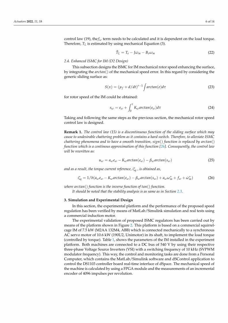
The experimental validation of proposed ISMC regulators has been carried out bymeans of the platform shown in Figure 2. This platform is based on a commercial squirrel-cage IM of 7.5 kW (M2AA 132M4, ABB) which is connected mechanically to a synchronousAC servo motor of 10.6 kW (190U2, Unimotor) in its shaft, to implement the load torque(controlled by torque). Table 1, shows the parameters of the IM installed in the experimentplatform. Both machines are connected to a DC bus of 540 V by using their respectivethree-phase Voltage Source Inverters (VSI) with a switching frequency of 10 kHz (SVPWMmodulator frequency). This way, the control and monitoring tasks are done from a PersonalComputer, which contains the MatLab/Simulink software and dSControl application tocontrol the DS1103 controller board real-time interface of dSpace. The mechanical speed ofthe machine is calculated by using a FPGA module and the measurements of an incrementalencoder of 4096 impulses per revolution.
Actuators 2022, 11, 18 7 of 14
Figure 2. Experiment platform for IM with load torque.
Table 1. Parameters of the M2AA 132M4 ABB Induction Motor 7.5 (rpm) and 1445 (rpm).
Symbol Rated Value
Bv 0.0105 [Kg m/(rad/s)]J 0.0503 [Kg m2]
Lm 0.1125 [H]Ls 0.1138 [H]Lr 0.1152 [H]σ 0.0346Rr 0.400 [Ω]
Rs 0.729 [Ω]
p 4 polesωm(n) 151.32 [rad/s] (1445[rpm])
φr 0.9030 [Wb]Isd 8.026 [A]Isq 20 [A]Is 15.3 [A]V 380 [V]PN 7500 [W]µ 87%
Three different design cases such as D1, D2 and PI have been applied to the sameinduction motor to validate the proposed enhanced regulator (D2 design). To run theexperiments, the IM is using the values of the nominal parameters for the IM, which havebeen listed in Table 1, and the IM has been tested at three different speeds. Furthermore,parameters values of the ISMC speed regulator are: Kω = 1600 and βω = 80. On theother hand, the uncertainty test takes a moment of inertia which is 60% lower than the
Actuators 2022, 11, 18 8 of 14
nominal value (J = 0.0201 kg·m2), while the rest of the machine parameters will be nominalvalues, then these parameters are Kω = 1700 and βω = 20. Regarding the adjustment ofthe two PI current regulators, both have been tuned by using a bandwidth of 3000 rad/sand a phase margin of 90 (Kpisd,q = 11.81, Kiisd,q = 2187) [27]. The mechanical speed PIregulator which is employed to compare with the enhanced ISMC speed regulator (D2design), have been tuned taking a bandwidth of 300 rad/s and a margin phase of 82(Kpωm = 5.64, Kiωm = 238). This way as faster as possible dynamics have been obtainedexperimentally by using PI regulators.
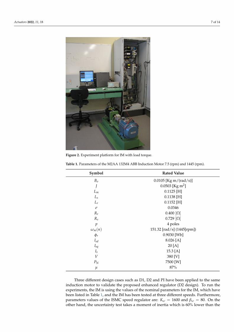
Figure 3(3-1) shows the performance of the machine by using a simulation test whenthe motor is working with a square speed reference of 1000 rpm with a period of 2 s,and the load torque is applied to the system in two steps: 10 Nm at the starting pointand 30 nm at t = 1.5 s. In the first graph, (a), the reference and real rotor speed can beobserved, and the second graph (b), shows the rotor speed error. As it can be seen, in thepresence of a sudden change in the load torque the mechanical rotor speed tracks thedesired speed properly with low error in steady-state (less than 1 rpm). The third graph,(c), shows the electromagnetic torque and load torque, where it can be appreciated thatelectromagnetic torque is smooth and consequently does not present any chattering. In (d)graph it can be seen that the stator torque current tracks the reference correctly. Moreover,this current is proportional to the electromagnetic torque which is also smooth and limitedto its rated value (20 A). Graph (e) shows how the rotor flux tracks its reference adequately.Furthermore, the good response of the rotor flux current can be presented as graph (f).Finally, as the torque current is limited, the stator currents are also limited to a similar valuethat has been shown in the (g), keeping protected the stator windings against over-currents.
(3-1) (3-2)
Figure 3. IM performance by using 1000 rpm reference speed and two load torque step changes:(3-1) simulation and (3-2) experimental (D2 design): (a) Rotor speed; (b) Speed error; (c) Te, TL;(d) Torque current; (e) Rotor flux; (f) Rotor flux current and (g) Stator current.
Actuators 2022, 11, 18 9 of 14
Figure 3(3-2) shows the performance of the machine by using the correspondingexperimental test to the simulation test shown in Figure 3(3-1). In the Figure 3(3-2), thegraphs (a) and (b) show that the speed tracking and the accuracy are very similar to thesimulation case, getting fast dynamics and speed error in steady-state is less than 2 rpm.Regarding the electromagnetic torque (c), it can be compared with its simulation case,concluding that both are very similar, smooth, and efficient. Moreover, the estimatedload torque is very similar to the load torque, which that demonstrates the estimatorworks properly. Graph (d) shows the reference and the real stator torque currents, whichcan be observed that the current tracking is very satisfactory and very similar to thesimulation case (the form is proportional to the electromagnetic torque and limited to20 A). In Figure 3(3-2), e and f graphs show how the rotor flux and rotor flux currentadequately track their references. It can be observed that the two stator currents, isd andisq are decoupled. Finally, due to the limited torque current, the stator currents are alsolimited to similar values (g). By comparing simulation and experimental case in Figure 3,it can be seen that the simulation and the platform experiment have the same behavior,which is proof of the experimental validation of the presented ISMC speed controller (D2design) and good system modeling.
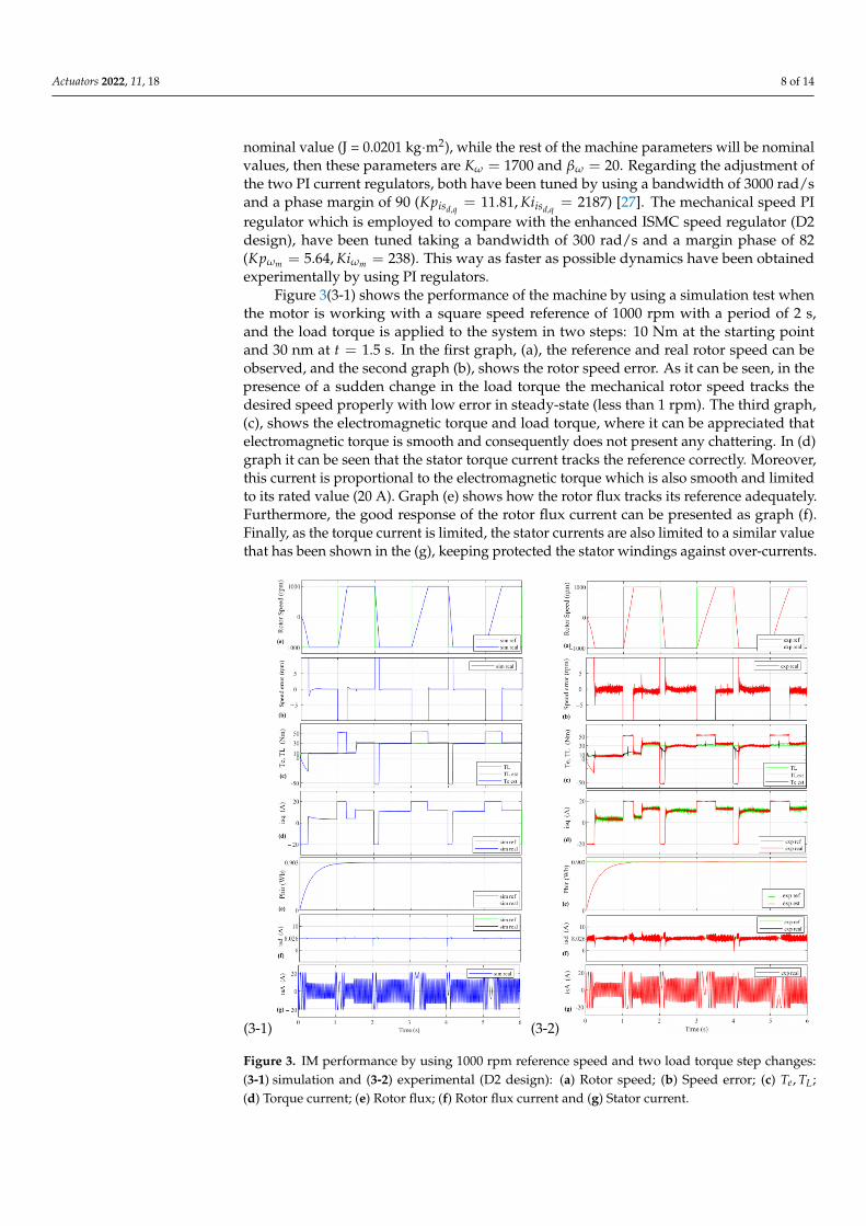
Figure 4 shows the experimental tests for performance comparison between the pro-posed ISMC speed controller (D2 design) and the conventional ISMC (D1 design) methodby using the same speed and load conditions in the test of Figure 3. This illustration pro-vides the sliding surface convergence and tracking speed performance for both controllers.It is evident in the zoom mode graphs that using the arctan() function of the speed error,instead of the sign() function, in the surface design, provides faster error convergence tozero. Moreover, the PI speed regulator performance is also added to show that despiteits performance being good its response is slower than the other two ISMC (D1 and D2designs).
Figure 4. Experimental tests for performance comparison between the proposed ISMC (D2 design)regulator and the conventional ISMC by using 1000 rpm reference speed (D1 design) and also withPI regulator.
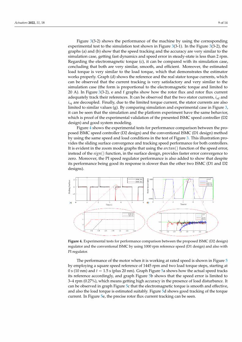
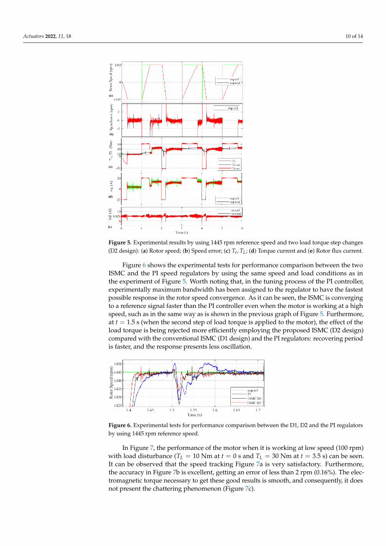
The performance of the motor when it is working at rated speed is shown in Figure 5by employing a square speed reference of 1445 rpm and two load torque steps, starting at0 s (10 nm) and t = 1.5 s (plus 20 nm). Graph Figure 5a shows how the actual speed tracksits reference accordingly, and graph Figure 5b shows that the speed error is limited to3–4 rpm (0.27%), which means getting high accuracy in the presence of load disturbance. Itcan be observed in graph Figure 5c that the electromagnetic torque is smooth and effective,and also the load torque is estimated suitably. Figure 5d shows good tracking of the torquecurrent. In Figure 5e, the precise rotor flux current tracking can be seen.
Actuators 2022, 11, 18 10 of 14
Figure 5. Experimental results by using 1445 rpm reference speed and two load torque step changes(D2 design): (a) Rotor speed; (b) Speed error; (c) Te, TL; (d) Torque current and (e) Rotor flux current.
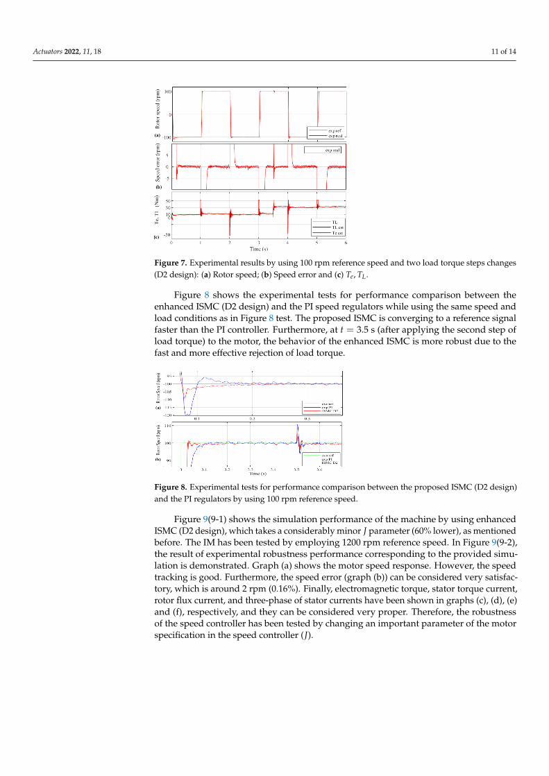
Figure 6 shows the experimental tests for performance comparison between the twoISMC and the PI speed regulators by using the same speed and load conditions as inthe experiment of Figure 5. Worth noting that, in the tuning process of the PI controller,experimentally maximum bandwidth has been assigned to the regulator to have the fastestpossible response in the rotor speed convergence. As it can be seen, the ISMC is convergingto a reference signal faster than the PI controller even when the motor is working at a highspeed, such as in the same way as is shown in the previous graph of Figure 5. Furthermore,at t = 1.5 s (when the second step of load torque is applied to the motor), the effect of theload torque is being rejected more efficiently employing the proposed ISMC (D2 design)compared with the conventional ISMC (D1 design) and the PI regulators: recovering periodis faster, and the response presents less oscillation.
Figure 6. Experimental tests for performance comparison between the D1, D2 and the PI regulatorsby using 1445 rpm reference speed.
In Figure 7, the performance of the motor when it is working at low speed (100 rpm)with load disturbance (TL = 10 Nm at t = 0 s and TL = 30 Nm at t = 3.5 s) can be seen.It can be observed that the speed tracking Figure 7a is very satisfactory. Furthermore,the accuracy in Figure 7b is excellent, getting an error of less than 2 rpm (0.16%). The elec-tromagnetic torque necessary to get these good results is smooth, and consequently, it doesnot present the chattering phenomenon (Figure 7c).
Actuators 2022, 11, 18 11 of 14
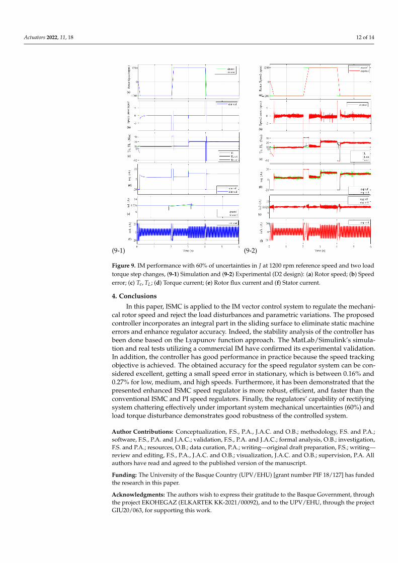
Figure 7. Experimental results by using 100 rpm reference speed and two load torque steps changes(D2 design): (a) Rotor speed; (b) Speed error and (c) Te, TL.
Figure 8 shows the experimental tests for performance comparison between theenhanced ISMC (D2 design) and the PI speed regulators while using the same speed andload conditions as in Figure 8 test. The proposed ISMC is converging to a reference signalfaster than the PI controller. Furthermore, at t = 3.5 s (after applying the second step ofload torque) to the motor, the behavior of the enhanced ISMC is more robust due to thefast and more effective rejection of load torque.
Figure 8. Experimental tests for performance comparison between the proposed ISMC (D2 design)and the PI regulators by using 100 rpm reference speed.
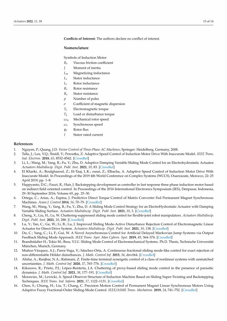
Figure 9(9-1) shows the simulation performance of the machine by using enhancedISMC (D2 design), which takes a considerably minor J parameter (60% lower), as mentionedbefore. The IM has been tested by employing 1200 rpm reference speed. In Figure 9(9-2),the result of experimental robustness performance corresponding to the provided simu-lation is demonstrated. Graph (a) shows the motor speed response. However, the speedtracking is good. Furthermore, the speed error (graph (b)) can be considered very satisfac-tory, which is around 2 rpm (0.16%). Finally, electromagnetic torque, stator torque current,rotor flux current, and three-phase of stator currents have been shown in graphs (c), (d), (e)and (f), respectively, and they can be considered very proper. Therefore, the robustnessof the speed controller has been tested by changing an important parameter of the motorspecification in the speed controller (J).
Actuators 2022, 11, 18 12 of 14
(9-1) (9-2)
Figure 9. IM performance with 60% of uncertainties in J at 1200 rpm reference speed and two loadtorque step changes, (9-1) Simulation and (9-2) Experimental (D2 design): (a) Rotor speed; (b) Speederror; (c) Te, TL; (d) Torque current; (e) Rotor flux current and (f) Stator current.
4. Conclusions
In this paper, ISMC is applied to the IM vector control system to regulate the mechani-cal rotor speed and reject the load disturbances and parametric variations. The proposedcontroller incorporates an integral part in the sliding surface to eliminate static machineerrors and enhance regulator accuracy. Indeed, the stability analysis of the controller hasbeen done based on the Lyapunov function approach. The MatLab/Simulink’s simula-tion and real tests utilizing a commercial IM have confirmed its experimental validation.In addition, the controller has good performance in practice because the speed trackingobjective is achieved. The obtained accuracy for the speed regulator system can be con-sidered excellent, getting a small speed error in stationary, which is between 0.16% and0.27% for low, medium, and high speeds. Furthermore, it has been demonstrated that thepresented enhanced ISMC speed regulator is more robust, efficient, and faster than theconventional ISMC and PI speed regulators. Finally, the regulators’ capability of rectifyingsystem chattering effectively under important system mechanical uncertainties (60%) andload torque disturbance demonstrates good robustness of the controlled system.
Author Contributions: Conceptualization, F.S., P.A., J.A.C. and O.B.; methodology, F.S. and P.A.;software, F.S., P.A. and J.A.C.; validation, F.S., P.A. and J.A.C.; formal analysis, O.B.; investigation,F.S. and P.A.; resources, O.B.; data curation, P.A.; writing—original draft preparation, F.S.; writing—review and editing, F.S., P.A., J.A.C. and O.B.; visualization, J.A.C. and O.B.; supervision, P.A. Allauthors have read and agreed to the published version of the manuscript.
Funding: The University of the Basque Country (UPV/EHU) [grant number PIF 18/127] has fundedthe research in this paper.
Acknowledgments: The authors wish to express their gratitude to the Basque Government, throughthe project EKOHEGAZ (ELKARTEK KK-2021/00092), and to the UPV/EHU, through the projectGIU20/063, for supporting this work.
Actuators 2022, 11, 18 13 of 14
Conflicts of Interest: The authors declare no conflict of interest.
Nomenclature
Symbols of Induction MotorBv Viscous friction coefficientJ Moment of inertiaLm Magnetizing inductanceLs Stator inductanceLr Rotor inductanceRr Rotor resistanceRs Stator resistancep Number of polesσ Coefficient of magnetic dispersionTe Electromagnetic torqueTL Load or disturbance torqueωm Mechanical rotor speedωs Synchronous speedψr Rotor fluxI Stator rated current
References1. Nguyen, P.; Quang, J.D. Vector Control of Three-Phase AC Machines; Springer: Heidelberg, Germany, 2008.2. Talla, J.; Leu, V.Q.; Šmídl, V.; Peroutka, Z. Adaptive Speed Control of Induction Motor Drive With Inaccurate Model. IEEE Trans.
Ind. Electron. 2018, 65, 8532–8542. [CrossRef]3. Li, L.; Wang, M.; Yang, R.; Fu, Y.; Zhu, D. Adaptive Damping Variable Sliding Mode Control for an Electrohydrostatic Actuator.
Actuators Multidiscip. Digit. Publ. Inst. 2021, 10, 83. [CrossRef]4. El Kharki, A.; Boulghasoul, Z.; Et-Taaj, L.K.; oussi, Z.; Elbacha, A. Adaptive Speed Control of Induction Motor Drive With
Inaccurate Model. In Proceedings of the 2019 4th World Conference on Complex Systems (WCCS), Ouarzazate, Morocco, 22–25April 2019; pp. 1–8.
5. Happyanto, D.C.; Fauzi, R.; Hair, J. Backstepping development as controller in fast response three phase induction motor basedon indirect field oriented control. In Proceedings of the 2016 International Electronics Symposium (IES), Denpasar, Indonesia,29–30 September 2016; Volume 65, pp. 25–30.
6. Ortega, C.; Arias, A.; Espina, J. Predictive Direct Torque Control of Matrix Converter Fed Permanent Magnet SynchronousMachines. Asian J. Control 2014, 16, 70–79. [CrossRef]
7. Wang, M.; Wang, Y.; Yang, R.; Fu, Y.; Zhu, D. A Sliding Mode Control Strategy for an ElectroHydrostatic Actuator with DampingVariable Sliding Surface. Actuators Multidiscip. Digit. Publ. Inst. 2021, 10, 3. [CrossRef]
8. Cheng, X.; Liu, H.; Lu, W. Chattering-suppressed sliding mode control for flexible-joint robot manipulators. Actuators Multidiscip.Digit. Publ. Inst. 2021, 10, 288. [CrossRef]
9. Lu, Y.; Tan, C.; Ge, W.; Li, B.; Lu, J. Improved Sliding Mode-Active Disturbance Rejection Control of Electromagnetic LinearActuator for Direct-Drive System. Actuators Multidiscip. Digit. Publ. Inst. 2021, 10, 138. [CrossRef]
10. Du, C.; Yang, C.; Li, F.; Gui, W. A Novel Asynchronous Control for Artificial Delayed Markovian Jump Systems via OutputFeedback Sliding Mode Approach. IEEE Trans. Syst. Man Cybern. Syst. 2019, 49, 364–374. [CrossRef]
11. Brandtstädter H.; Tokio M.; Buss, V.I.U. Sliding Mode Control of Electromechanical Systems. Ph.D. Thesis, Technische UniversitätMünchen, Munich, Germany.
12. Muñoz-Vázquez, A.J.; Parra-Vega, V.; Sánchez-Orta, A. Continuous fractional sliding mode-like control for exact rejection ofnon-differentiable Hölder disturbances. J. Math. Control Inf. 2015, 34, dnv064. [CrossRef]
13. Ahifar, A.; Ranjbar, N.A.; Rahmani, Z. Finite-time terminal synergetic control of a class of nonlinear systems with unmatcheduncertainties. J. Math. Control Inf. 2020, 37, 765–776. [CrossRef]
14. Kikuuwe, R.; Prieto, P.J.; López-Rentería, J.A. Chattering of proxy-based sliding mode control in the presence of parasiticdynamics. J. Math. Control Inf. 2021, 38, 177–191. [CrossRef]
15. Morawiec, M.; Lewicki, A. Speed Observer Structure of Induction Machine Based on Sliding Super-Twisting and BacksteppingTechniques. IEEE Trans. Ind. Inform. 2021, 17, 1122–1131. [CrossRef]
16. Chen, S.; Chiang, H.; Liu, T.; Chang, C. Precision Motion Control of Permanent Magnet Linear Synchronous Motors UsingAdaptive Fuzzy Fractional-Order Sliding-Mode Control. IEEE/ASME Trans. Mechatron. 2019, 24, 741–752. [CrossRef]
Actuators 2022, 11, 18 14 of 14
17. Morawiec, M.; Lewicki, A.; Wilczynski, F. Speed observer of induction machine based on backstepping and sliding mode forlow-speed operation. Asian J. Control 2021, 23, 636–647. [CrossRef]
18. Ilten, E.; Demirtas, M. Fractional order super-twisting sliding mode observer for sensorless control of induction motor, Compel.Int. J. Comput. Math. Electr. Electron. Eng. 2019, 38, 878–892. [CrossRef]
19. Veselic, B.; Perunicic-Drazenovic, B.; Milosavljevic, C. High-Performance Position Control of Induction Motor Using Discrete-TimeSliding-Mode Control. IEEE Trans. Ind. Electron. 2008, 55, 3809–3817. [CrossRef]
20. Comanescu, M. Minimum Time Speed Control of the Induction Motor Drive Using Discrete Time Sliding Mode. In Proceedingsof the 2020 International Symposium on Power Electronics, Electrical Drives, Automation and Motion (SPEEDAM), Sorrento,Italy, 20–22 June 2020; pp. 213–218.
21. Barambones, O.; Garrido, A.J.; Maseda, F.J. Integral sliding-mode controller for induction motor based on field-oriented controltheory. IET Digit. Library 2007, 1, 786–794. [CrossRef]
22. Comanescu, M. An Induction-Motor Speed Estimator Based on Integral Sliding-Mode Current Control. IEEE Trans. Ind. Electron.2009, 56, 3414–3423. [CrossRef]
23. Oliveira, C.; Aguiar, M.; Monteiro, J.; Pereira, W.; Paula, G.; Almeida, T. Vector Control of Induction Motor Using an IntegralSliding Mode Controller with Anti-windup. J. Control Autom. Electr. Syst. 2016, 27, 169–178. [CrossRef]
24. Gou, L.; Wang, C.; Zhou, M.; You, X. Integral Sliding Mode Control for Starting Speed Sensorless Controlled Induction Motor inthe Rotating Condition. J. IEEE Trans. Power Electron. 2016, 35, 4105–4116. [CrossRef]
25. Slotine, J.J.E.; Li, W. Applied Nonlinear Control; Prentice Hall: Englewood Cliffs, NJ, USA, 1991.26. Khalil, H.K.; Quang, J.D. Nonlinear Control; Pearson Higher: London, UK, 2014.27. Mohan, N. Advanced Electric Drives: Analysis, Control, and Modeling Using MATLAB/Simulink; John Wiley & Sons: Hoboken, NJ,
USA, 2014.