advanced space storable propellants for outer planet exploration
TRANSCRIPT

ADVANCED SPACE STORABLE PROPELLANTS FOR OUTER PLANET EXPLORATION
Daniel P. Thunnissen' User Technology Associates, Inc.
Pasadena, California 91 101
Carl S. Guernsey', Raymond S. Baker:, and Robert N. Miyake$ Jet Propulsion Laboratory, California Institute of Technology
Pasadena, California 91 109
An evaluation of the feasibility and mission performance benefits of using advanced space storable propellants for outer planet exploration was performed. For the purpose of this study, space storable propellants are defined to be propellants which can be passively stored without the need for active cooling. A secondary purpose o f this study was to provide guidance as to the limits, benefits, and possible methods of passively storing such mild cryogenic propellants for deep space missions. The study was composed of four distinct efforts. First, candidate propellants were defined and their relevant properties determined. Second, a propellant combination analysis using the Two Dimensional Kinetics 1997 (TDK97) program was conducted. Third, a thermal storage design was analyzed. Lastly, a mission and systems analysis was performed for three outer planetary missions. The missions are representative in complexity, duration, and requirements for a variegated set of outer planet exploration missions currently being considered by NASA. Nonetheless, the analysis conducted and outlined in this paper determined that outer planet exploration using advanced storable propellants was feasible and offered a significant benefit in delivered payload compared to previous design studies.
MR
m n P I T t V
AV
P gc
P
V
NOMENCLATURE
area Beattie-Bridgeman constants mass flow rate thrust coefficient propulsion constants diameter thrust figure of merit molecular mass (molecular weight) mixture (oxidizer-to-fuel) ratio mass number of stages pressure impulse temperature time volume
change in velocity molar specific volume density conversion factor (9.80665 m-lbm/lbf-sec* in the Imperial system of units, 1 in SI system of units)
1 + CZ/Pave
subscripts: ave b o s t g
CPU e
c
f f_stgl firel-tan k-loaded
GR hold-l/p I
i s tg2 inj lin?-AV max
ox-tan k ox-tank-loaded
ox
pres prestank pres-tank f i t e l pres-tank f i x - l o a d e d
pres-tan k-ox
*Systems Engineer; Member AIAA 'Principal Engineer, Thermal and Propulsion Engineering Section; Member AIAA $Staff Engineer, Propulsion Flight Systems Group $Principal Engineer, Thermal and Propulsion Engineering Section
universal gas constant, 8314.51 Jikmol-K
average relevant stage at bum out combustion chamber central processing unit nozzle exit final stage 1 final fuel tank fully loaded with fuel Guernsey-Rapp hold-upiresidual propellant initial stage 2 initial injected limiting change in velocity maximum oxidizer oxidizer tank oxidizer tank fully loaded with oxidizer pressurant gas pressurant tank pressurant tank for the fuel pressurant tank for the fuel fully loaded with pressurant pressurant tank for the oxidizer
Prop prop-loaded prop-tank ProP-dry prop_stgl pr op-1 vet
SP strirc t thermal totalstg P-fP
pres-tank-ox-loaded pressurant tank for the oxidizer fully loaded with pressurant propellant total propellant loaded propellant tank dry propulsion system stage 1 propellant wet propulsion system specific stage structure total thermal control relevant stage total density specific
superscripts:
pres-tank-i j
pres-tank f
prop-tank-i
prop-tank f
stage number in the pressurant tank at launch in the pressurant tank at end of stage burn in the propellant tank at launch in the propellant tank at end of stage burn
ISTRODI’CTION
Chemical propulsion for planetary exploration missions has for decades depended on the use of propellants that can be passively stored at Earth-ambient conditions. By contrast, launch vehicle propulsion systems routinely use cryogenic propellants (such as liquid hydrogen) that offer higher specific impulse than is available from Earth-storable propellants. Unfortunately, the application of such propellants to long-duration space missions is complicated by the need to limit or eliminate boil off of the cryogenic propellants. The development of zero-G vent systems and/or cryocooler technologies for such purposes is just now in its infancy and will make considerable demands on spacecraft resources such as mass and power.
It has long been recognized that there is a middle ground between the extremes of using Earth storable propellants and “hard” cryogens such as liquid hydrogen: space storable propellants.’ In this context, a “space storable” propellant is one that can be stored in interplanetary space without the need for either venting or cryogenic cooling. Conventional Earth-storable propellants fit into this category, as do a number of mildly cryogenic propellant candidates. The use of such propellants has the potential to significantly increase the performance of chemical propulsion systems for missions of planetary exploration without
requiring the technology investment or impacts on spacecraft resources that would be entailed in adopting the use of deeply cryogenic propellants.
Purpose of Study
A great deal of work was done during the 1970’s to identify the benefits of space storable propulsion for planetary e x p ~ o r a t i o n . ~ ~ ~ , ” ’ , ~ ~ ~ ~ ~ ~ ~ However, much of the underlying documentation of this work has been lost over the years and many of the studies suffer from one or both of two weaknesses: they were performed by staunch advocates of the technology andlor they did not provide an “apples-to-apples” comparison of potential space storable propulsion systems to the system-level performance of other space storable concepts or conventional propulsion systems.
This study attempts to take a fresh and unbiased look at the potential for space storable propulsion by addressing the following questions:
* What are the attractive candidates for space storable propulsion systems, and what are their performance characteristics under a uniform set of assumptions?
What propellant storage temperatures are truly obtainable by passive means without resorting to exotic or unproven technologies?
What are the system-level performances of attractive space storable propellant combinations under a uniform set of assumptions?
In addressing the last of these questions, a further question arose:
To what extent does advanced chemical propulsion have a role to play as the use of solar electric propulsion becomes more routine, and how might its utility be affected by the emergence of new technologies such as aerocapture?
The overall motivation behind this study is to provide guidance as to the limits, benefits, and possible methods of passively storing mild cryogenic propellants for deep space missions. In particular, this guidance is to be given in the context of the last question posed above.
Approach
The first step was to define candidate propellants and determine relevant properties that are required for evaluation of their performance in a propulsion system.
2 American Institute of Aeronautics & Astronautics
This was accomplished primarily through brainstorming and literature searches. The intent was to cast a wide net and try to make sure that at least all major classes of propellant were addressed, although it was clearly not possible to address every possible propellant. This was followed by a down-select based on propellants which were clearly not space storable or had properties (such as easy detonability) which made their use in spacecraft propulsion extremely doubtful.
Once a set of candidate fuels and oxidizers were selected, propellant performance calculations were performed for all possible Combinations of these fuels and oxidizers using the Two Dimensional Kinetics 1997 (‘FDK97) computer code which is described later in this report. Assumptions used in these calculations were held constant for all propellant combinations in an attempt to get a true “apples to apples” comparison. Once these results were obtained, the candidate propellant combinations were ranked using four different figures-of-merit (FOMs) which relate to expected system-level performance. One of these figures-of-merit, the “limiting A V FOM”, was judged to be the most likely to reflect actual system-level performance and that ranking was used in a final down- select for the system studies. Rather than simply selecting the n highest-ranked combinations, combinations were selected starting from the top of the list but taking account of unique storability issues and/or development histories.
In parallel with the first two efforts, a thermal storage analysis was conducted to provide guidance on feasible temperatures for passive space storage of propellants. This was done as a point design for propellant tanks of a fixed size and mass. Scaling relations were then developed to allow this model to be applied in the system performance assessments.
A system-level performance analysis was then applied to the three outer planet missions described above. This assessment relied on a common set of assumptions for all propellant combinations except for the propellant performance, propellant properties (density and temperature) and thermal control requirements.
This paper is an abbreviated version of a final report that was produced.“
CANDIDATE PROPELLANTS & THEIR RELEVANT PROPERTIES
This section begins with a discussion of the candidate propellants initially chosen for this study. A brief overview of the qualitative reasoning for eliminating certain oxidizers and fuels from consideration follows.
The section ends with a discussion of propellant properties.
Candidate Propellants
A list of 37 propellants was generated for preliminary consideration. Table 1 lists the candidate oxidizers for this study. Four oxidizers listed in Table 1 can also serve as monopropellants: H202, HANiGlycine, HAN/MEO, and HANITEAN.
Table 1 Candidate Oxidizers Name Symbol or
Abbreviation Anhydrous Nitric Acid HN03
Chlorine Pentafluoride C1Fj Chlorine Trifluoride CIF3
Bromine Pentafluoride BrF
FLOX 82%F2, 18%02 Fluorine F2 Hydrogen Peroxide H202 Hydroxy lammonium HAN/Gly cine NitrateiGly cine Hydroxylaminonium Nitrate HANIMEO
/Methanol Hydroxylanimonium Nitrate HAN/TEAN
/Triethanol Ammonium Nitrate
Acid Inhibited Red Fuming Nitric IRFNA
Mixed Oxides ofNitrogen 10 MON-IO Mixed Oxides of Nitrogen 25 MON-25 Mixed Oxides of Nitrogen 30 MON-30 Nitrogen Tetroxide (MON-3) Oxygen LOX or O2 Oxygen Difluoride OFz
Red Fuming Nitric Acid RFNA Tetrafluorohy drazine N2F4
NTO or N204
Perchloryl Fluoride CIO3F
Table 2 lists the candidate fuels for this study. Hydrazine is the only fuel listed in Table 2 that can also serve as a monopropellant. The oxidizers and fuels listed in Table 1 and Table 2, respectively, do not constitute a complete list of possible propellants. The oxidizers and fuels listed were initially chosen qualitatively from dozens to hundreds of potential propellants based on their heritage, use in previous design studies, or current development. The focus of this activity was liquid bipropellants. Solids, gels, and tripropellants were not considered.
3 American Institute of Aeronautics & Astronautics

Table 2 Candidate Fuels Name Symbol or
Acetylene (Ethyne) Aerozine-50 (50% N2HdJ50%
UDMH) Alumizine Benzene Ethanol Ethylene Hydrazine Hydrogen Hydyne (UDMH 60%/DETAa
40%) Kerosene Lithium (liquid) Methane Methanol Monomethyl Hydrazine Pentaborane Propane Unsy mmetric
Abbreviation C2H2 A50
nla C6H6
CZHSOH C2H4 N2H4 LH2
MAF-4 or U- DETA
RP-I or CHI yl
LLi CH4
MMH B5H9
CH30H
C3H8 UDMH
Dimethylhydrazine ”DETA = diethylenetriamine H(C2H4NH)2NH2
Initial Propellant Down Select
Five oxidizers and five fuels were eliminated from consideration prior to any propellant performance predictions. This section provides a brief description on why each of the propellants was eliminated.
Oxidizers Eliminated
HN03, MON-IO, MON-30, and RFNA were eliminated from consideration because they have similar or inferior properties to oxidizers that were kept in the pool for additional analysis. Both HN03 and RFNA are “represented” by IRFNA, which was kept for additional investigation. Both MON-10 and MON-30 are “represented” by MON-25, which was also kept for additional investigation. For propellant combinations where either IRFNA or MON-25 proves to be a promising oxidizer, the eliminated oxidizers HN03, MON-10, MON-30, and RFNA could be revisited. Finally, HANlTEAN was ruled out because its development program has been terminated. It had poor performance (compared to the other two HAN based monopropellants listed in Table 1 ) and several unresolved issues.”
Fuels Eliminated
The reasons for eliminating the five fuels C2H2, A.50, alumizine, LH2, and LLi from further consideration are
more varied. CzH2 is highly flammable, highly explosive fuel that is difficult to store in liquid phase and hence, not a credible propellant. A50 has similar properties to N2H4 and MMH, which were both kept for additional analysis. Alumizine contains 43% A1 powder in a N2H4 gelling agent. The challenges of developing a set of leak-tight valves suitable for a long- life propulsion system when this much solid material is contained in the propellant was felt to make this fuel undesirable for such applications. Furthermore, performance predictions using the Two Dimensional Kinetic (TDK) software would not account for losses due to two-phase flow and hence would not be comparable to the other propellants. LH2 was ruled out since it is not space storable by any passive means. Finally, LLi was eliminated from consideration since it is not space storable as a liquid due to its very high melting point.
Propellant Properties
Based on the qualitative elimination process previously described, 13 oxidizers and 12 fuels advanced to a full propellant combination analysis that is presented in the following section. Detailed properties such as density, heat of formation, melting point, boiling point, toxicity, and storability of these 25 propellants are provided in Ref. 10. Also listed in Ref. 10 are limited properties for the five oxidizers and five fuels that were not considered for further analysis.
An additional property of interest to this study is the vapor pressure of these propellants. Fig. 1 plots the vapor pressure for several cryogens and near-cryogen propellants as a function of temperature.l2>I3
_ _ _ _ ~ ___
I00 150 200 1 O i
Fig. 1 Vapor Pressures for Cryogens & Near-
50 Temperatiiie (K)
Cryogen Propellants.
4 American Institute of Aeronautics & Astronautics

PROPELLANT COMBINATION ANALYSIS Fig. 2 plots the vapor pressure for Earth-storable propellants as a function of t e m p e r a t ~ r e . ' ~ , ~ ~ . ' ~
200 250 300 350 400 Temperature (K)
Vapor Pressures for Earth-Storable Propellants.
Neither tabular data nor an equation was available for determining the vapor pressure of ClF5. However, The vapor pressure of ClF5 at 293 K (20 "C) is estimated to be 3.4 bar (49.3 psi).I5
Table 3 provides the vapor pressure at temperatures of interest, the critical temperature, and critical pressure for several Vapor pressures are exploited in the mission and systems analysis that is discussed in the Mission & System Analysis section.
Table 3 Vapor Pressure, Critical Temperature, and Critical Pressure for Several Propellants
Propellant Vapor Critical Critical Pressure Temperature Pressure
. . . . . . . . . . . . . . . . . . . . . . . . .
ClF j F2
H202 LOX ( 0 2 )
MAF-4 (U-DETA)
MMH N2H4 NTO (N204)
190.7'
174.6b 1335.6'
98.7b 1013.2' 15.Sd
105.6d 1 .4d 96.2 2.0
339.9d
0.2d
416.15 143.95
732.15 154.35
558.15
585 653 43 1
213.45
5.516 5.573
2 1.684 5.036
5.40 1
8.237 14.692 9.928 5.016
This section discusses the propellant combination analysis that was performed with Two Dimensional Kinetic 97 (TDK97) computer analysis program. The section begins with an explanation of the TDK analysis including assumptions, the method used, and a summary of results. A discussion of the various figures of merit that were used to compare the different propellant combinations follows. Based on these figures of merit, the various propellant combinations are ranked and down selected for further systems analysis.
_ _ _ _ _ _ _ _ - _ _ _ _ _ _ - Two Dimension Kinetics LT_-KJ_&3lySb
This section begins with a brief explanation of the Two Dimensional Kinetic (TDK) program. A detailed explanation of the assumptions used in the TDK analysis follows. A summary of results is then introduced. Ref. 10 provides detailed tabular results and discusses the performance analysis performed on the HAN-based monopropellants that were considered.
Explanation of TDK_ - _
The Two Dimensional Kinetic (TDK) computer program is a primary tool in applying the JANNAF liquid rocket thrust chamber performance prediction method. Originally developed in the late 1960s, the code has undergone improvements and modifications in the decades since. For example, a Mass Addition Boundary Layer (MABL) module, which allows secondary exhaust products to be injected tangential to the primary flow, was added to the code in the 1990s.
As the name suggests, the TDK97 code represents the (February) 1997 release of the computer p r ~ g r a m . ' ~ TDK97 estimates performance parameters such as specific impulse, thrust, mass flow rate, and thrust coefficient. In TDK, the theoretical specific impulse is calculated using the One-Dimensional Equilibrium (ODE) module which was adapted from the Chemical Equilibrium and Applications/Chemical Equilibrium and Transport (CEA/CET) codes.18 The ODE module is used to calculate the theoretical performance of the propellants at a given chamber pressure, mixture ratio and propellant energy content. A kinetic reaction file of the combustion products is not needed when using ODE. In fact, only limited thermodynamic data are needed for the propellants themselves, as they are treated as a source of enthalpy and atoms only.
The full JANNAF performance prediction method begins with an ODE calculation discussed. It then estimates the magnitude and interactions of various loss
5 American Institute of Aeronautics & Astronautics
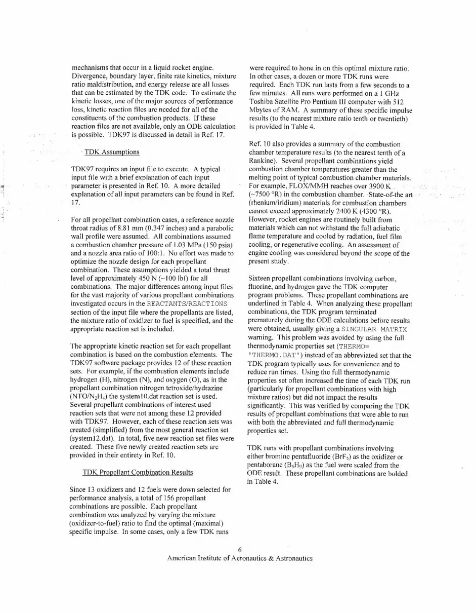
mechanisms that occur in a liquid rocket engine. Divergence, boundary layer, finite rate kinetics, mixture ratio maldistribution, and energy release are all losses that can be estimated by the TDK code. To estimate the kinetic losses, one of the major sources of performance loss, kinetic reaction files are needed for all of the constituents of the combustion products. If these reaction files are not available, only an ODE calculation is possible. TDK97 is discussed in detail in Ref. 17.
TDK Assumptions
TDK97 requires an input file to execute. A typical input file with a brief explanation of each input
explanation of all input parameters can be found in Ref. 17.
j parameter is presented in Ref. 10. A more detailed
For all propellant combination cases, a reference nozzle throat radius of 8.81 mm (0.347 inches) and a parabolic wall profile were assumed. All combinations assumed a combustion chamber pressure of 1.03 MPa (1 50 psia) and a nozzle area ratio of 100: 1. No effort was made to optimize the nozzle design for each propellant combination. These assumptions yielded a total thrust level of approximately 450 N (-100 Ibf) for all combinations. The major differences among input files for the vast majority of various propellant combinations investigated occurs in the REACTANTS/REACTIONS section of the input file where the propellants are listed, the mixture ratio of oxidizer to fuel is specified, and the appropriate reaction set is included.
The appropriate kinetic reaction set for each propellant combination is based on the combustion elements. The TDK97 software package provides 12 of these reaction sets. For example, if the combustion elements include hydrogen (H), nitrogen (N), and oxygen (0), as in the propellant combination nitrogen tetroxideihydrazine (NTO/N,H,) the system1 O.dat reaction set is used. Several propellant combinations of interest used reaction sets that were not among these 12 provided with TDK97. However, each of these reaction sets was created (simplified) from the most general reaction set (system12.dat). In total, five new reaction set files were created. These five newly created reaction sets are provided in their entirety in Ref. 10.
TDK Propellant Combination Results
Since 13 oxidizers and 12 fuels were down selected for performance analysis, a total of 156 propellant combinations are possible. Each propellant combination was analyzed by varying the mixture (oxidizer-to-fuel) ratio to find the optimal (maximal) specific impulse. In some cases, only a few TDK runs
were required to hone in on this optimal mixture ratio, In other cases, a dozen or more TDK runs were required. Each TDK run lasts from a few seconds to a few minutes. All runs were performed on a 1 GHz Toshiba Satellite Pro Pentium 111 computer with 512 Mbytes of RAM. A summary of these specific impulse results (to the nearest mixture ratio tenth or twentieth) is provided in Table 4.
Ref. I O also provides a summary of the combustion chamber temperature results (to the nearest tenth of a Rankine). Several propellant combinations yield combustion chamber temperatures greater than the melting point of typical combustion chamber materials. For example, FLOWMMH reaches over 3900 K (-7500 OR) in the combustion chamber. State-of-the art (rheniumhridium) materials for combustion chambers cannot exceed approximately 2400 K (4300 OR). However, rocket engines are routinely built from materials which can not withstand the full adiabatic flame temperature and cooled by radiation, fuel film cooling, or regenerative cooling. An assessment of engine cooling was considered beyond the scope of the present study.
Sixteen propellant combinations involving carbon, fluorine, and hydrogen gave the TDK computer program problems. These propellant combinations are underlined in Table 4. When analyzing these propellant combinations, the TDK program terminated prematurely during the ODE calculations before results were obtained, usually giving a SINGULAR MATRIX warning. This problem was avoided by using the full thermodynamic properties set (THERMO=
TDK program typically uses for convenience and to reduce run times. Using the full thermodynamic properties set often increased the time of each TDK run (particularly for propellant combinations with high mixture ratios) but did not impact the results significantly. This was verified by comparing the TDK results of propellant combinations that were able to run with both the abbreviated and full thermodynamic properties set.
THERM0 . DAT I ) instead of an abbreviated set that the
TDK runs with propellant combinations involving either bromine pentafluoride (BrF,) as the oxidizer or pentaborane (B5H9) as the fuel were scaled from the ODE result. These propellant combinations are bolded in Table 4.
6 American Institute of Aeronautics & Astronautics
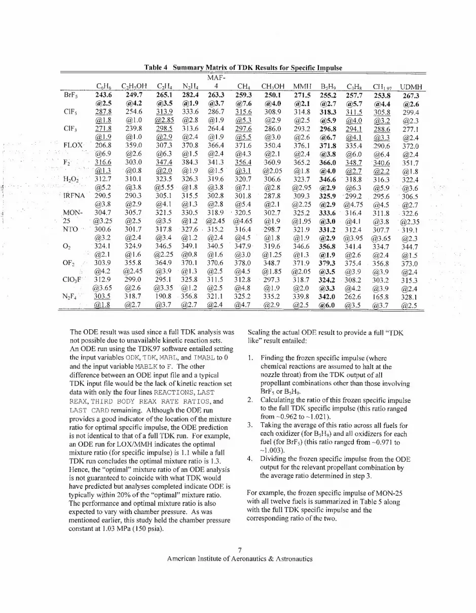
Table 4 Summary Matrix of TDK Results for Specific Impulse MAF-
C6H6 C2HjOH C2Hj N2H4 4 CH4 CHlOH MMH B5H9 C3H8 CHI97 UDMH 265.1 282.4 263.3 259.3 250.1 271.5 255.2 257.7 253.8 267.3 BrFj 243.6
(92.5 C1Fj 287.8
a FLOX 206.8
@6.9
@5.2 IRFNA 290.5
@3.8
25 @3.25 NTO 300.6
(93.2 0 2 324.1
OFz 303.9 @4.2
@3.65
MON- 304.7
(92.1
CIO,F 312.9
NpF4 303.5
249.7 @4.2 254.6
239.8
359.0 @2.6 303.0
310.1 @3.8 290.3 @2.9 305.7 0 2 . 5 301.7 @2.4 324.9 0 1 . 6 355.8 @2.45 299.0 @2.6 3 18.7
@1.0
@ l . O
@0.8
@3.5 313.9 @,2.85 298.5 a 307.3 @6.3 347.4 a 323.5 (535.55 305.1 @4.1 321.5 @3.5 3 17.8 (93.4 346.5 @2.25 364.9
295.1
190.8
@3.9
(93.35
@1.9 (33.7 333.6 286.7 @2.8 @1.9 313.6 264.4 @2.4 @1.9 370.8 366.4 @1.5 @2.4 384.3 341.3 @1.9 @1.5 326.3 319.6 @1.8 @3.8 315.5 302.8 @1.3 @2.8 330.5 318.9 @1.2 @2.45 327.6 315.2 @1.2 @2.4 349.1 340.5 @0.8 @1.6 370.1 370.6 0 1 . 3 @2.5 325.8 311.5 @1.2 @2.5 356.8 321.1
@7.6 315.6 a 297.6
371.6 (34.3 356.4 a 320.7 @7.1 301.8
320.5 @4.65 316.4
347.9 @3 .0 378.0
3 12.8 @4.8 325.2
(95.4
@4.5
0 4 . 5
@4.0 308.9 @2.9 286.0 @3 .O 350.4
360.9 a 2 . 0 5 306.6 @2.8 287.8
302.7 @I .9 298.7
319.6 @ I .25 348.7
@I .85 297.3 @1.9 335.2
0 2 . 1
(32.1
@1.8
(32.1 314.8 @2.5 293.2 @2.6 376.1 @2.4 365.2 @1.8 323.7 @2.95 309.3 @2.25 325.2
@I .95 321.9 @1.9 346.6 @1.3 371.9 @2.05 318.7
339.8 (92.0
@2.7 318.3
296.8 @6.7 371.8
366.0 @4.0 346.6 @2.9 325.9 @2.9 333.6 @3.0 331.2 @2.9 356.8 @1.9 379.3
324.2
342.0
(95.9
(33.8
@3.5
@3.3
a 5 . 7 311.5
204.1 @4-l 335.4 @6.0 348.7 a 318.8 @6.3 299.2
316.4 @4.1 312.4
341.4 @2.6 375.4
308.2 @4.2 262.6
@4.75
(93.95
@3.9
@4.4 305.8 a 288.6 0,33
340.6
(95.9
0 4 . 5
433.8
290.6 @6.4
316.3
295.6
311.8
307.7 @3.65 334.7 @2.4 356.8
303.2
165.8
(93.9
0 3 . 9
@2.6 299.4 0 2 . 3 277.1 @2.4 372.0 @2.4 351.7 @ I .8 322.4 0 3 . 6 306.5 @2.7 322.6 @2.35 319.1 @2.3 344.7 @1.5 373.0 @2.4 315.3 @2.4 328.1
a 2 . 7 (93.7 B2.7 R2.4 @4.7 @, 2.9 (9 2.5 B6.0 (93.5 @ 3.7 @ 2.5
The ODE result was used since a full TDK analysis was not possible due to unavailable kinetic reaction sets. An ODE run using the TDK97 sofhvare entailed setting the input variables ODK, TDK, MABL, and IMABL to 0 and the input variable MABLK to F. The other difference between an ODE input file and a typical TDK input file would be the lack of kinetic reaction set data with only the four lines REACTIONS, LAST REAX, THIRD BODY REAX RATE RATIOS, and LAST CARD remaining. Although the ODE run provides a good indicator of the location of the mixture ratio for optimal specific impulse, the ODE prediction is not identical to that of a full TDK run. For example, an ODE run for LOX/MMH indicates the optimal mixture ratio (for specific impulse) is 1 . I while a full TDK run concludes the optimal mixture ratio is 1.3. Hence, the “optimal” mixture ratio of an ODE analysis is not guaranteed to coincide with what TDK would have predicted but analyses completed indicate ODE is typically within 20% of the “optimal” mixture ratio. The performance and optimal mixture ratio is also expected to vary with chamber pressure. As was mentioned earlier, this study held the chamber pressure constant at 1.03 MPa (1 50 psia).
Scaling the actual ODE result to provide a full “TDK like” result entailed:
1. Finding the frozen specific impulse (where chemical reactions are assumed to halt at the nozzle throat) from the TDK output of all propellant combinations other than those involving BrF5 or BjH9. Calculating the ratio of this frozen specific impulse to the full TDK specific impulse (this ratio ranged from -0.962 to -1.021). Taking the average of this ratio across all fuels for each oxidizer (for BjH9) and all oxidizers for each fuel (for BrFj) (this ratio ranged from -0.971 to
Dividing the frozen specific impulse from the ODE output for the relevant propellant combination by the average ratio determined in step 3.
2.
3.
-1.003). 4.
For example, the frozen specific impulse of MON-25 with all twelve fuels is summarized in Table 5 along with the full TDK specific impulse and the corresponding ratio of the two.
7 American Institute of Aeronautics & Astronautics
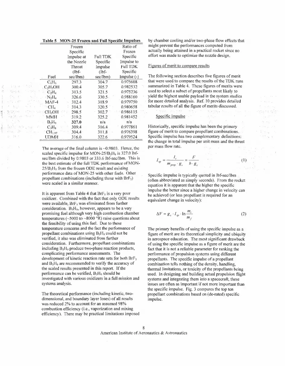
Table 5 MON-25 Frozen and Full Specific Impulses Frozen Ratio of Specific Frozen
Impulse at Full TDK Specific the Nozzle Specific Impulse to
Throat Impulse Full TDK (Ibf- (Ibf- Specific
Fuel sec/lbm) secilbm) Impulse (-) C6H6 297.3 304.7 0.975608
CZHSOH 300.4 305.7 0.982532 C2H4 313.5 32 1.5 0.975236 N2H4 326.6 330.5 0.988160
MAF-4 3 12.4 3 18.9 0.979750 CH4 314.3 320.5 0.980658
CH30H 298.5 302.7 0.9861 15 MMH 319.2 325.2 0.981452 B5H9 327.0 d a nla
309.4 316.4 0.97786 1 C3H8 304.4 311.8 0.976398 CHI 97
UDMH 316.0 322.6 0.979524
The average of the final column is -0.9803. IHence, the scaled specific impulse for MON-25/B5Hg is 327.0 Ibf- sec/lbm divided by 0.9803 or 333.6 Ibf-sec/lbm. This is the best estimate of the full TDK performance of MON- 25/BsHc, from the frozen ODE result and existing performance data of MON-25 with other fuels. Other propellant combinations (including those with BrF5) were scaled in a similar manner.
It is apparent from Table 4 that BrF5 is a very poor oxidizer. Combined with the fact that only ODE results were available, BrF5 was eliminated from further consideration. B5H9, however, appears to be a very promising fuel although very high combustion chamber temperatures (-5000 to -8000 OR) raise questions about the feasibility of using this fuel. Due to these temperature concerns and the fact the performance of propellant combinations using B5H9 could not be verified, it also was eliminated from further consideration. Furthermore, propellant combinations including B5H9 produce two-phase reaction products, complicating performance assessments. The development of kinetic reaction rate sets for both BrF5 and B jH9 are recommended to verify the accuracy of the scaled results presented in this report. If the performance can be verified, BsHo should be investigated with various oxidizers in a full mission and systems analysis.
The theoretical performance (including kinetic, two- dimensional, and boundary layer loses) of all results was reduced 2% to account for an assumed 98% combustion efficiency (Le., vaporization and mixing efficiency). There may be practical limitations imposed
by chamber cooling andlor two-phase flow effects that might prevent the performances computed from actually being attained in a practical rocket since no effort was made to optimize the nozzle design.
Figures of merit to compare results
The following section describes five figures of merit that were used to coinpare the results of the TDK runs summarized in Table 4, These figures of merits were used to select a subset of propellants most likely to yield the highest usable payload in the system studies for more detailed analysis. Ref. I O provides detailed tabular results of all the figure of merits discussed.
Specific impulse
Historically, specific impulse has been the primary figure of merit to compare propellant combinations. Specific impulse has two complementary definitions: the change in total impulse per unit mass and the thrust per mass flow rate.
Specific impulse is typically quoted in Ibf-secilbm (often abbreviated as simply seconds). From the rocket equation it is apparent that the higher the specific impulse the better since a higher change in velocity can be achieved (or less propellant is required for an equivalent change in velocity):
The primary benefits of using the specific impulse as a figure of merit are its theoretical simplicity and ubiquity in aerospace education. The most significant drawback of using the specific impulse as a figure of merit are the fact that it is not a reliable parameter for ranking the performance of propulsion systems using different propellants. The specific impulse of a propellant combination tells nothing of the density, handling, thermal limitations, or toxicity of the propellants being used. In designing and building actual propulsion flight systems and integrating them into a spacecraft, these issues are often as important if not more important than the specific impulse. Fig. 3 compares the top ten propellant combinations based on (de-rated) specific impulse.
8 American Institute of Aeronautics & Astronautics

380 , 1600 8
Fig. 3 Top Ten Propellant Combinations Based on Specific Impulse.
The average density figure of merit is defined as the average density of the propellant combination at the mixture ratio of interest:
The average propellant density is significant in that propellants having lower density will require larger, heavier tanks and pressurization systems. Therefore, it is possible for a propellant combination that delivers high specific impulse to have poor overall system performance if it has low average density (pressure-fed liquid oxygen and hydrogen is the consummate example). The primary benefits of using the average density as a figure of merit are its simplicity and practicality. The primary drawback of using the average density as a figure of merit is the fact that it tells nothing of the performance of the propellant combination of interest besides incorporating the mixture ratio. On its own it is not a credible figure of merit but when combined with the specific impulse provides a more comprehensive figure of merit (see the sections that follow). Fig. 4 compares the top ten propellant combinations based on average density.
Fig. 4 Top Ten Propellant Combinations Based on Average Density.
Guernsey-Rapp Figure of Merit
In 1988 C. Guernsey and D. Rapp of the Jet Propulsion Laboratory (JPL) proposed a new propulsive figure of merit.” This figure of merit was intended to introduce propellant density and produce a “specific impulse- like” figure of merit. This figure of merit, hereafter referred to as the Guernsey-Rapp FOM, is defined as the derivative of propulsion system total impulse with respect to propulsion system mass:
(4)
The Guernsey-Rapp FOM assumes that the propulsion system dry mass is linearly related to the propellant volume:
The propulsion system wet mass is therefore:
The Propulsion System Design Tool (PSDT, see the section entitled “Mission & System Analysis”) was used to estimate the values of c1 and c2 for two typical Earth storable bipropellant systems using two different propellant tank technologies. The PSDT was used to
9 American Institute of Aeronautics & Astronautics

generate curves of propulsion system wet mass as a function of propellant mass. The analysis was performed on both an NTOiMMH and an NTO/N2H4 system. Fig. 5 shows the propulsion system wet mass as a function of propellant mass for both titanium and composite overwrapped pressure vessel (COPV) tank technologies.
Piopellmt M a s (kg)
Fig. 5 Propulsion System Wet Mass as a Function of Propellant Mass for Typical Bipropellant
Systems.
Equation (6) can be rewritten as
The constants c I and data generated by the PSDT, shown in Fig. 5. c2 i s then calculated from
can then be derived from the
by using the following equation:
Table 6 summarizes the results for the two systems studied.
Table 6 Derived Constants of the Guernsey-Rapp FOM for Four Propulsion System Types
System Tank Type cI (kg) c2 (kg/m3) NTO/MMH Ti 35.0 101.6 NTOM2H4 Ti 34.7 104.9 NTO/MMH COPV 32.4 62.4 NTO/N2H4 COPV 32.5 64.4
The PSDT predicts a linear relationship between propulsion system wet mass and propellant mass, as expected. For a given tank technology, there is only about a 3% difference in c2 between the two propellant combinations.
The values of c2 were then averaged for each tank technology resulting in a c2 of 103.3 kg/m3 for titanium propellant tanks and 63.4 kg/m3 for COPV propellant tanks. These values were used to calculate the Guernsey-Rapp FOM for all propellant combinations studied. In reality, the general application of these values of c2 to all propellants i s not accurate. For example, spacecraft using cryogenic propellants must use significant thermal hardware to isolate the tanks. The mass of this hardware depends on both the tank volume and propellant mass (see the section entitled “Thermal Storage Analysis”). Therefore, these systems will tend to have a higher c2 and a lower Guernsey- Rapp FOM than Earth storable systems with comparable specific impulses. However, the intent here is to broadly sort the propellant combinations to select a subset for more detailed analysis. The results of a more rigorous analysis are compared in the section entitled “Mission & System Analysis” to this broad application of c2 in the Guernsey-Rapp FOM.
Returning to equation (6) which can be solved for the propellant mass:
Expressing the total impulse as a function of the propellant mass:
Hence, the Guernsey-Rapp FOM is:
The primary benefit of the Guernsey-Rapp FOM is that it accounts for both specific impulse and average propellant density in a nonarbitrary manner. The primary drawback of the Guernsey-Rapp FOM is that the meaning of figure of merit is not entirely clear: how does overall system performance correlate with the derivative of impulse with respect to wet mass? Fig. 6 compares the top ten propellant combinations based on the Guernsey-Rapp FOM for both titanium and composite overwrapped pressure vessel (COPV)
10 American Institute of Aeronautics & Astronautics

- 0 0
0 0 r
O O O P il T:
0 0 0 9 71 0
0 0 0 8 f 0-
00001 g

this general application of a single value of c2 to all propellant combinations is also inaccurate. However, it is only applied here to select a subset of promising propellant combinations for more detailed analysis (see the section entitled “Mission & System Analysis”).
Density specific inioulse
The density specific impulse is defined as the product of the average density and specific impulse (which were defined earlier):
The primary benefit of using the density specific impulse as a figure of merit is its accounting of both the specific impulse and average density of a propellant combination (arguably the two most important parameters). The density specific impulse is also widely used in industry. The primary drawback of using the density specific impulse as a figure of merit is the arbitrariness of simply multiplying these two parameters. The relative importance of these two parameters is simply assumed to be equal, which the preceding discussions illustrate is not necessarily the case. Fig. 8 compares the top ten propellant combinations based on density specific impulse.
500
Fig. 8 Top Ten Propellant Combinations Based on Density Specific Impulse.
Rankings and Down Select
The rankings summarized in Fig. 3 through Fig. 8 indicate several propellant combinations that are worthy of further analysis. A total of ten were selected for a full mission and systems analysis. Three propellant combinations, F2/N2H4, OF2/MAF-4, and OF2/N2H4, have high rankings in most of the figures of merit presented. Three propellant combinations C1F5/N2H4, H202/N2H4, and LOX/MMH, have high potential and
interesting characteristics. Four propellant combinations, LOX/N2H4, NTO/MMH, NTOM2H4, and LOWCH4, represent current state-of-the-art, have existing development programs, or have been the topic of possible development programs. The rankings of these ten propellant combinations by the various figures of merit discussed are presented in Table 7 below.
Table 7 Summary of Propellant Combination Rankings
Propellant Combination I,, prrlje FO~~(( , I ( FOMI,,,~ I , ,I)
F2/N2H4 1 21 1 1 1 OF2IMAF-4 OF2N2Hj CIFy”H4 H202NH4 LOXiMMH
NTO/MMH LOXM2H4
NTO/N,H4
12 32 8 13 36 I1 45 3 41 51 40 51 32 135 32 27 124 28 63 77 61 50 59 50
3 5 5 7
22 2 40 37 44 110 32 84 60 69 41 4s 100 138 - LOXICH4 30 144 39 -__
Noticeably absent from Table 7 are the oxidizers IRFNA, MON-25, and G103F and the fuels C2H501H and C2H4. Propellants combinations using these propellants provided poor performance in virtually all rankings. Each of the ten propellant combinations that were selected for a full mission and systems analysis is described briefly below:
This combination was actively studied until the early 1980s. It provides extremely high specific impulse combined with high density yielding the highest ranking in four of the five figures of merit. Unfortunately, it suffers from significant safety concerns related to the extreme reactivity of the fluorine oxidizer. However, there exists a very significant body of work addressing material compatibility issues and ground safety issues from the NASA technology programs in the 1970s and early 1980s and from Air Force work conducted during the 1 9 8 0 ~ . ~ - ~ Storing LF, passively at 120 K requires a pressure in excess of 1.3 MPa (1 88 psi).
OFJMAF-4 -
This propellant combination shares many of the positive and negative characteristics of F&H4 but offers better storability for both the oxidizer and fuel. However, OF2 is not established oxidizer and MAF-4 has not been used significantly since the early space program in the 1960s. It is worth noting that OF2 can
12 American Institute of Aeronautics & Astronautics

be stored at 120 K at a pressure under 100 kPa (1 5 psi) to quantify the advantage over LF2.
engine.2o As with previous combinations mentioned, it is somewhat penalized by the relatively high (-27.5 K) freezing point of the hydrazine.
NTOiMMH This propellant combination is very similar to the OF2/MAF-4 propellant combination previously discussed. This combination is attractive from a systems perspective since it does provide for the possibility of a N2H4 monopropellant system, albeit at the cost of a much higher fuel freezing temperature (-275 VS. -189 K).
This propellant combination is readily storable in flight and on the ground. It offers both higher specific impulse and higher density than conventional storable propellants. The oxidizer can be passively stored at Earth ambient conditions, eliminating the need for ground cooling provisions required by the mild cryogens such as F2. This propellant combination was considered for Strategic Defense Initiative (SDI) systems in the 1980s and there is some technology base on which to build. However, it does suffer from the high freezing point of hydrazine. Furthermore, there is no current U.S. source of production for the oxidizer.
This propellant combination offered a surprisingly high FOM. Furthermore, it has the advantage of being able use either propellant as a monopropellant for reaction control of the spacecraft. The long-term storage of H202 without decomposition is a significant challenge. Propellant calculations in this document refer to 100% H202, while typically the highest commercial purity is on the order of 70%.
LOWMMH
This propellant combination provided the highest limiting AV FOM for a propellant combination that uses LOX as the oxidizer. Both these propellants are very well established and understood.
This combination was considered because there has been recent work at two rocket engine companies to develop engines using these propellants. In particular, the TRW Space & Technology division in Redondo Beach, CA (now part of Northrop Grumman) achieved a specific impulse in excess of 3.53 Ibf-sec/lbm at a mixture ratio of -0.8 for a 900 N (200 Ibf) class
This combination represents state-of-the-art for chemical propulsion. The conventional storable propellant combination of NTO and MMH has flown hundreds of times in space since its development early in the space program. Engines built by several vendors exist at various thrust levels for this propellant combination. The performance achieved by an actual NTOiMMH 445 N main engine is -324 lbf-sec/lbm at a mixture ratio of 1.65.” This specific impulse is higher than the de-rated TDK result obtained in this study (315.5 Ibf-secilbm at 1.9). Nonetheless, the TDK result was used in the subsequent mission and systerns analysis to be consistent with the remainder of the propellant combinations investigated.
This combination also represents state-of-the-art chemical propulsion. Although a more recent propellant combination development than NTOMMH, this combination is now well established from its successful use in the Lockheed-Martin A2100 line of spacecraft and several well publicized deep-space missions (Mars Global Surveyor, NEAR, Mars Odyssey, etc.). Several engines exist in the 445 N class for this propellant combinations. The performance achieved by an actual NTO/N2H4 445 N main engine is greater than 324 Ibf-secilbm at a mixture ratio of -0.8.5.** This specific impulse is higher than the de- rated TDK result obtained in this study (321.0 Ibf- secilbm at 1.2). Nonetheless, the TDK result was used in the subsequent mission and systems analysis to be consistent with the remainder of the propellant combinations investigated.
-4 LOXiCH
This propellant is often discussed in l i t e r a t ~ r e . ’ ~ , ~ ~ , ~ ~ Liquid oxygen and methane are logical propellant choices for in-situ propellant production missions to Mars based on the SabatieriElectrolysis (WE) process, since both propellants can be produced from the Martian atmosphere provided hydrogen is available.26 This propellant combination suffers from a very low limiting AVFOM that needs to be examined in detail.
13 American Institute of Aeronautics & Astronautics

THERMAL STORAGE ANALYSIS
The following section describes the assumptions and analysis method for thermal control of advanced space storable propellants.
Historv of Space Storable Propellant
Since space flight began in the late 1950's, propellant storage on spacecraft for attitude control and AV requirements has been an issue. Earth storable propellants, though storable at temperature levels around room temperature, have relatively stringent temperature level and stability requirements. The driving requirement for the most common propellants in use today is maintaining a minimum tempeiature above the propellant's freezing point. Propellants are in general not allowed to freeze in order to allow maneuvers and reaction control throughout the missioo and to prevent bursting of propellant lines or components due to uncontrolled thawing. As an example, the flight allowable temperature level for hydrazine (N2H4) is between -276 to -3 18 K (+3 to +45 "C). To preclude propellant freeze, most thermal control designs set the lower temperature at 10 K (10 "C) above the freeze temperature, at 286 K (+13 "C) . Other propellants such as monomethyl hydrazine (MMH) and nitrogen tetroxide (NTO) have an allowable temperature ranges that go below 273 K (0 "C). Upper allowable temperature ranges are often determined by the limitations of the test facilities in which the hardware is qualified, although there can be real limitations introduced by thermal stability of rocket engines or the chemical stability of the propellants themselves. Typical upper allowable flight temperature ranges for storable propellants range from 3 18 to 333 K (45 to 60 "C) . These are rarely driving requirements for the thermal control of the propellants. Thermal control of these propellants is accomplished using a combination of tank heaters and multilayer insulation (MLI). In some cases waste heat from spacecraft electronics or power systems can be used to minimize the electrical power required to avoid propellant freezing.
Future Space Storable Thermal DesigdHardware
Future missions may benefit from the use of advanced propellants, which provide increased specific impulse and/or density when compared to conventional storable propellants. Advanced low-temperature storage will be required for many of these propellants. An initial evaluation has been done which concludes that a passive system can be developed to store propellants at about 120 K (-153 "C) using existing technology.
Passive storage of propellant at 120 K (-153 "C) for long periods is feasible, but unproven and non-trivial. This goal presents many challenges in thermal isolation and control that will require substantial development. One example is the mechanical support structure and mechanisms required for large tanks and isolation required for the lines. The requirement to support the tank and lines for launch loads, both acceleration and vibration requires sufficient structure, which in general implies relatively large mechanical support systems with potentially large conducted thermal loads.
The following is a baseline for propellant system evaluation. Fig. 9 shows a schematic representation of the basic tank thermal control concept
Front View
Tank supports
Shield/ Insulatiot
.e---? --\ Unobstructed view of space
Side View
- Unobstructed view of space
Fig. 9 Propellant Tank Thermal Control Concept Sketch.
The baseline was used to size the thermal subsystem for the propulsion module, which was then scaled based on tank size, mass, and area. The baseline assumed for this evaluation is a one-meter diameter propellant tank. This tank is supported at the top and bottom with a large boss, through which are f i l l and drain lines. The support structure is assumed to be tube struts. For stability, it is assumed that the supports are one bi-pod mount and one tripod mount. The struts are made of titanium and have a length on the order of 75 cm, are about 5 cm in diameter, and have a wall thickness of
14 American Institute of Aeronautics & Astronautics
0.075 cm. This tank is assumed to be mounted in a dedicated propulsion module, with clearances for tank installation and radiant heat transfer around the tanks. This assumption is used to determine the surface area of the propulsion module so that the environmental heating and thermal losses can be calculated. For a bipropellant module there will be two propellant tanks, and two pressurant tanks. For the 1 m tanks assumed in the reference design, this leads to a propulsion module about 2.5 meters in diameter and a height of about I .5 meters.
The storage of most cryogenic propellants at or below their normal boiling point would require the development of systems that provide storage temperatures below 100 K (-173 "C). As an example, a liquid oxygen (LOX) storage tank will have to be held at a temperature level of -80 K unless the LOX is stored at an elevated pressure. While current Dewar technology holds its working fluid at temperatures less than 20 K, all these systems provide limited operational times. An example is the Space Infrared Telescope Facility (SIRTF), which has a large cryogenic Dewar, but has a total mission life of 30 months. Cruise times for outer planet niissions are on the order of many years. An example is the current Cassini mission and the future Jupiter Icy Moons Orbiter (JIMQ) mission, which have transit times on the order of 5 or more years. While it may be possible, with improvements in technology, to lower the threshold for passive storage below 120 K, it is clear that long-term storage with zero boil-off at temperatures as low as 20 K (-253 "C) will require the use o f active cooling systems.
However, as previously stated, the evaluation of technology extension utilizing current knowledge of materials and design, the lowest temperature practical for a passive thermal control system is on the order of 120 K (-153 "C). In order to bridge this gap between the normal boiling point of attractive propellants and the minimum storage temperature, the vapor pressure of each propellant was investigated as a function of temperature. It was previously shown in the section entitled "Candidate Propellants & their Relevant Properties" that the vapor pressures of all of the down- selected propellants are manageable at 120 K (-153 "C). There is no intrinsic reason that propellants need to be stored below their normal boiling point. For example, nitrogen tetroxide has a normal boiling point of 294 K (21 "C), but is commonly stored at temperatures up to 323 K (50 "C). What is necessary is to maintain the pressure in the feed system above the propellant vapor pressure all the way to the combustion chamber to prevent two-phase flow. When injector stability concerns are considered, this means that the propellant tank operating pressure will need to be maintained at or
above about twice the vapor pressure of the propellant at its storage temperature.
The thermal control concept incorporates several key features: The spacecraft bus temperature was assumed to be 293 K (20 "C). The primary thermal design assumptions for the baseline thermal tank design are summarized below:
e
e
e
Tank is designed to radiate and is shielded from the Sun, spacecraft, and other thermal sources as shown in Fig. 9. Surface area where energy is radiated is one half of the spherical area (1 .S7 m') of the tank. A shield with the effectiveness of a 20-layer MLI blanket shields the tank from the sun and spacecraft bus. The opening in the shield is 1.4 m in diameter, The tank has a (20 layer) MLI blanket around the spacecraft side (emissivity = 0.01). The tank is painted black with an emissivity of 0.90. Five titanium struts for structural support whose length, diameter, and thickness are 0.75 m, 2.5 cm, and I mm, respectively. The struts have thermal isolators where they attach to the tank. Two propellant lines: a f i l l line and a supply line (1.27 cni internal diameter 3 10 stainless steel with a length of 30 cm and a wall thickness of 0.75 mm). Note that the requirement that the propellant tank be protected from solar exposure so that it can radiate to deep space puts a significant operational constraint on the spacecraft
Analysis
The evaluation method used developed a mass estimate for thermal control systems for passive space storable propellant systems. This basic method uses the thermal balance calculations with various ranges from the Sun. This provides the external environmental input, which in general drives the thermal design of propulsion modules as well as thermal requirements for bus mounted propulsion systems.
The evaluation in general is for flight systems that have a solar range of 0.7 AU to Pluto range (which is about 40 AU, which essentially is an interstellar mission). For systems that have flight ranges that go closer to the Sun than 0.7 AU, specific thermal control systems, as well as operational constraints may be necessary. Behind an effective thermal sunshade, the effects on the temperature of passively cooled hardware can be quite independent of solar distance. This is illustrated by the flight temperature data shown in Fig. IO.
15 American Institute of Aeronautics & Astronautics

250 - --23 V
--I23
-171 ~~ -~~ ~~ ~ ~
1 2 3 4 5 6 LOOo
Distance fiotn Sun (AU) Fig. 10 Flight Temperature Variations as a
Function of Solar Distance.
These are temperatures measured in the telescope barrel section of the Near-infrared IMaging Spectrometer (NIMS) on the Galileo spacecraft. A cover and heaters protected this instrument from contamination until the spacecraft returned to 1 AU for the final time. After the cover was jettisoned and the heaters were turned off, the temperature at this point in the telescope quickly dropped to approximately 138 K (-135 "C) and showed little variation with further increases in the distance from the sun. The focal plane of this instrument was passively cooled to an operating temperature of about 80 K.
For 120 K (-153 "C) systems, a passive thermal rejection system is required along with flight restrictions. The size and mass of such a thermal rejection system has been estimated for a I-meter diameter 120 K propellant tank. Further, the 120 K propellant tank also requires a 120 K pressurant tank. The mass of the thermal shield has been estimated. The effect of operational limitations must be evaluated for each mission and its scientific requirements.
Results
For nominal room temperature propellants, current thermal control techniques provide the control required, but if lower temperatures or wider flight ranges especially for flights closer than 0.7 AU, extended thermal control techniques and designs are required.
In general the mass requirements are based on surface area, and the mass is scalable using the size of the tanks and pressure tanks. The mass required for lines, and engine assemblies is included, and assumes that the lines and thrusters are mounted on the propulsion module. The heat loads resulting from the
aforementioned assumptions are summarized in Table 8 and Table 9:
Table 8 Conducted Energy to the Tank Conducted Energy to the Tank
from the ...
spherical Fill and Hemi-
Tank Supply support Temp. Spacecraft Lines Struts Total 0 (W) (W) (W) A W L
0.93 14.46 60 6.55 6.98 80 6.52 6.38 0.85 13.75
0.77 13.02 100 6.47 5.78 0.69 12.25 -- 5.18 120 6.38 -
Table 9 Net Energy Transfer to the Tank - _________ Total
Hemi- Tank Heat Conducted spherical Rejection Energy to
Tank Capability the Tank Temp. (IC) (W) (W) -- Net (W)
60 1.04 14.46 -13.42 80 3.80 13.75 -9.95 100 8.00 13.02 -5.02 120 16.60 12.25 - 4.35
Negative numbers in Table 9 indicate a net heat absorption and temperature rise. Initial results shows that with current technology propellants can be space stored to a lower level of 120 K (-153 "C).
Table 10 shows the results for the baseline case. The baseline assumes that the propellant tanks are spheres having diameters of 1 m. The pressure tanks are spheres having diameters of 0.5 m.
Table 10 Results for Thermal Sizing of Baseline System"
Option 2: One Tank
Option Stored at Option 1: 300K; other 3:
Both at 120K (in Both Tanks kg) Tanks Stored 300 120 Stored
a t300K K K at 120K Option (in kg) Tank Tank (in kg)
Surface Area Dependent Thermal Mass Primary Shield nia nla 2.08 1.65 Secondary nla n/a 1.5 3.75 Shield
16 American Institute of Aeronautics & Astronautics

Option 2: One Tank
Option Stored at Option 1 : 300K; other 3:
Both at 120K (in Both Tanks kg) Tanks Stored 300 120 Stored
a t300K K K at 120K Option (in kg) Tank Tank (in kg) Propellant Tank 3.2 3.2 1.53 1.44 MLI/Surface Coat Propellant Tank 0.25 0.25 nla nla Heater Pressnrana Tank 0.8 0.8 0.42 0.4 MLIisurface Coat Pressurant Tank 0.1 0.1 nla nla Heaters Structure MLI 21.5 24 nla 26.5
Tank Mass Dependent Thermal Mass Propellant Tank 2.2 2.2 3.5 3.5 Thermal Isolator Pressurant Tank 0.5 0.5 0.9 0.9 Thermal Isolator
Valve Plate 0.9 0.9 0.75 0.75 Thermal "propellant tank diameters = 1 m each; propellant tank wet mass = 300 kg each; pressurant tank diameters =
0.5 m each; pressurant tank wet mass = 10 kg each
Fixed Mass
For the case where both tanks operate at 120 K, combining the two low-temperature tanks requires more surface area for separation and field of view, thus the total area sensitive mass requires a 2.5 multiplication factor over a single tank. This assumes that the two propellant tanks are the same size (1 meter diameter each) and the pressure tanks are the same size (0.5 meter diameter each). This MLI is slightly less than for the Option 2 120 K tank because the shields provide a slightly better isolation since both of the propellant and pressure tanks in the propulsion module are at 120 K. Consequently, the structure will be cooler (since there is no 300 K tank). The "structure MLI" is specifically for insulation for the structure that supports the two propellant tanks, two pressure tanks, and the rocket engine mechanical support structure. The structure may be a little larger to support the larger shields and there may be more spacing between the tanks. The estimates in
Table 10 were then used to scale the thermal system mass based on tank diameters and masses. The final formulation is as follows:
For Option 1:
For Option 2:
MISSION & SYSTEM ANALYSIS
The goal of the mission and systems analysis was to determine the benefit of the selected propellant combinations to relevant mission scenarios. This analysis considered not only the performance of the propellant, but also its impact on the thermal and propulsion system design. This section describes the mission scenarios, the system study approach, and the results of the system study.
Mission Scenarios
Three mission scenarios were selected from a recent paper for this study to cover a range of AV requirements and injected mass assumption^.^^ Table 1 1 summarizes the mission scenarios that were studied. All scenarios assumed launch on a Delta-IV heavy vehicle. Note that the payload masses are as calculated from Ref. 27. The results of the current study are based on different assumptions.
17 American Institute of Aeronautics & Astronautics

Table 11 Mission Scenarios Studied from Ref. 27 Payload for Payload for
AV Injected Specific lmpulse Specific Impulse Payload for Required Mass of 325 Ibf- of 370 lbf- Aerocapture
Mission ( k d s e c ) (kg) secilbm (kg) secilbm (kg) (kg) Neotune Orbit Insertion 6.1 3423.8 -78.4 80.5 1680.2 Jupiter Orbit Insertion 1.4 2335.3 1339.4 1438.5 729.3 Saturn Post-Aerocapture 3.3 1656.4 374.8 NA NA
The term “payload” refers to the spacecraft system delivered to the final orbit, not including the propulsion stage or stages and its associated structural, cabling, and thermal hardware. The mission trajectories chosen from Ref. 27 are not necessarily optimized for the use of chemical propulsion. For example, the very high AV required for the Neptune mission is in part a result of the use of solar elecrric propulsion in the inner solar system to inject the probe on a relatively fast trip to Neptune. There are trades that could be done between trip time and orbit insertion A V that are not within the scope of this study. Therefore, the actual injected masses for these missions given in this study shorrld not be considered as absolutes, but in relative terms.
Neptune Orbit Insertion
The Neptune Orbit Insertion mission was selected for its difficulty. This mission requires the highest AV and injected mass combination that might still be tractable with advanced space storable propellants. The destination is a 4,000 km x 430,000 km elliptical obit with an apoapsis just beyond the moon Triton. This mission requires an Earth departure hyperbolic excess velocity (C3) of 23.7 km2/sec2. It then uses a Solar Electric Propulsion (SEP) stage to provide 6.8 km/sec of AV over the 10.5 year cruise to Neptune. The trajectory includes both a Jupiter and Venus flyby/gravity assist. Delivered payloads for this scenario from Ref. 27 show very meager results for chemical systems, especially when compared to a system using aerocapture.
Jupiter Orbit Insertion
The Jupiter Orbit Insertion mission resides at the opposite end of the spectrum with a relatively low AV and moderate injected mass. The destination for this mission is a 1,000 km x 1,880,000 km orbit with its apoapsis at Callisto. The mission requires a C3 of 85 km2/sec2. This scenario represents a class of missions in which systems using chemical propulsion deliver more payload than systems using aerocapture, based on the results in Ref. 27.
Saturn PoshAerocaptur-riapsis Raise
The Saturn niission is unique in that it requires both aerocapture and a large amount of propulsive AV for a periapsis raise maneuver The results summarized in Ref. 27 suggest that this mission is not possible without aerocapture technologies. This mission begins with an Earth departure C3 of 23.5 km2/sec2. A SEP stage provides 6.1 km/sec of AVover the 6.7 year cruise. The spacecraft captures into an orbit around Saturn using aerocapture. It then uses a chemical system to perform a periapsis raise maneuver to reach its destination orbit of 120,000 km circular for ring observations in the Cassini gap. This scenario represents a class of missions where there may be synergy between aerocapture and advanced space storable propellants.
Major Assumptions and Summary of Regu&
Table 12 compares the assumptions made in Kef. 27 to those made in this study. In general, this study attempts to make a more realistic accounting of system impacts of using advanced space storable propellants. Staging was also considered for each of the maneuvers studied in order to maximize delivered payload.
Table 12 Comparison of Assumptions between Ref.
Assumption Ref. 27 This Study Number of 1 1 o r 2
stages State-of-the-art 325 sec As calculated from
storable TDK analysis with a specific 2% derating factor impulse (321.0 sec for
27 and this Study
NTO/N,Hd) Future advanced 370 sec As calculated from
storable TDK analysis with a chemical 2% derating factor propellant (376.6 sec for
impulse spec i fi c F2mZH4)
18 American Institute of Aeronautics &: Astronautics

Assumption Ref. 27 This Study Chemical 0.2 Tabulated using
propulsion module dry mass/
propulsion equipment list for specific propellant combo,
propellant structural coefficient, mass and thermal equipment
scaling Stack support 0.05 Stage structural
structural inassisup ported wet mass/ mass = 0.0526 propulsion module mass
Thermal m a s Included Scaled based on in thermal equipment !ist chemical and propellant storage propulsion requirements (see module section entitled dry mass “Thermal Storage
Analysis”)
’ For each mission scenario, the state-of-the-art space storable system, NTO/N2H4, was analyzed using both 1 and 2 stages. For two-stage systems, the AV was split evenly. The remaining propellant combinations were then analyzed using the number of stages that yielded the highest delivered payload for the NTO/N2H4 system. Table 13 shows the results of the stage trade study for each mission scenario.
Table 13 Comparison of Delivered Payload for 1
Delivered
Payload for a Two Stage Single Stage System
and 2 Stage systems using NTO/N2H4
Delivered Payload for a
Mission Scenario System (kg) (kg) Neptune Orbit -125 159
Jupiter Orbit 1217 1155
Saturn Post- 301 334
Insertion
Insertion
Aerocapture Periapsis Raise
A comparison of the results show a lower predicted delivered mass than that reported in Ref. 27. This is a result of a lower specific impulse and a more conservative estimate of propulsion stage dry mass. The remainder of this section details the assumptions and analysis procedure that went into generating Table 13.
Systems Analysis Amroach and Other Assumptions
The systems analysis was performed using the JPL Team X Propulsion System Design Tool (PSDT). Team X is an integrated concurrent engineering design team using Microsoft Excel based design tools that are integrated to provide a real-time rapid design environment2’ The PSDT has been used in hundreds of spacecraft mission design studies in Team X. For this study, the PSDT has been used independent of the Team X environment to design and size the propulsion subsystem.
The PSDT takes many inputs including stage Ab’, initial mass, specific impulse, mixture ratio, propellant tank pressure and temperature, pressurant tank pressure and temperature, and many others to compute propulsion system design characteristics. The outputs from the PSDT include propukion system dry mass, propellant mass, pressurant mass, tank size, and residual propellant mass. The PSDT is capable of designing a system with up to three stage? or a single stage with up to three different types of systems.
__ P r o m i o n Schematic & Equipnient List
The first major input into the PSDT is an equipment list based on a propulsion system schematic. For this study, the Europa Orbiter system schematic was used as a baseline. Europa Orbiter assumes a monopropellant hydrazine system for attitude control, which was not considered in this study of primary propulsion stages. Fig. 11 shows the schematic for this study.
G ox
Pyrotechnic valve (normally closed) Pyrotechnic valve (normally open) Filter
Fig. 11. Baseline Propulsion System Schematic.
19 American Institute of Aeronautics & Astronautics

It was assumed that this schematic was appropriate for all propellant combinations in use. The propulsion stages designed in this study provide AVonly. A reaction control system (RCS) is assumed to be part of the delivered payload. One advantage of using hydrazine fuel is that a small portion of the fuel could be used for attitude control using monopropellant hydrazine thrusters, if having a separate RCS as part of the payload were undesirable.
Baseline components were assumed based on this schematic and a total system thrust of 450 N. Table 14 shows the mass-equipment list for this schematic. The total fixed mass of this system is 24.9 kg.
’.
Table 14 Fixed Propulsion Mass Equipment List‘ ~- Total Mass
Unit Total with Mass Mass Cont. Cont.
__- Component Qty. (kg) ( k d (W (kg) Gas service
HP latch valve Solenoid valve HP transducer Cas filter NC pyro. valve NO pyro. valve Liquid service
Test service
LP transducer Liquid filter Mass flow
control Temp. sensor Lines, fittings,
Biprop main
vdl\ie
valve
valve
misc.
engine
4 0.01 0.04 30 2 0.35 0.70 30 4 0.35 1.40 30 2 0.06 0.12 30 2 0.15 0.30 30 10 0.12 1.20 30 2 0.12 0.24 30
4 0.28 1.12 30
4 0.01 0.04 0 8 0.06 0.48 30 2 0.72 1.44 30
2 0.03 0.06 30 17 0.03 0.51 30
1 5.00 5.00 50
1 5.76 5.76 30
0.05 0.91 1.82 0.16 0.39 1.56 0.3 1
1.46
0.04 0.62 1.87
0.08 0.67
7.50
7.49 TOTAL 24.93 fHP =high pressure; LP = low pressure; NO = normally open; N C =-normally closed
Governing System Equations
Next, mission AVand injected mass are input. Propellant is calculated using the classical rocket equation, rearranged for propellant mass:
(19)
The propellant is then split into fuel and oxidizer using the mixture ratio:
and
f n I r a 1 = fn/”,i/l - mo, (21)
The initial mass for the second stage of two stage systems was calculated by subtracting the stage 1 propellant and an estimated stage 1 burnout mass from the injected mass. The stage 1 burnout mass is iterated in the final steps of the process to converge the design.
Once the propellant mass was calculated, the tanks were sized using the PSUT The PSDT takes many inputs to size the propellalit and pressurant tanks. Table 15 lists the assumptions for propellant tank sizing.
Table 15 Propellant Tank Inputs to PSDT
Characteristic Unit Value Number of tanks 1 Ullage at launch YO 10 Volume contingency YO 10
MEOPg MPa 2.1h Burst factor of safety 1.5
Hold-up/Residual plus margin YO 2.7 Tank shape sphere
Expulsion device type tension Liquid outlet tube diameter mm 9.525 Cas inlet tube diameter mm 6.35 Boss radius mm 50.8 Mount style boss Boss outlet orientation radial Boss type double Tank material titanium Min. fabrication thickness mm 0.508 Machining tolerance mm 0.0762 gmaximum expected operating pressure; h300 psi
std. surface
20 American Institute of Aeronautics & Astronautics

Characteristic Unit Value Pressure of presssurant @ MPa 27.6'
All propellant tanks used these assumptions, with the following exceptions:
1.
2.
F2 tanks were sized for an MEOP of 2.8 MPa (400 psi) due to fluorine's high vapor pressure at 120 K. OF2 and LOX tanks are aluminum due to the incompatibility of these propellants with titanium.
With these assumptions, the PSDT generates tank masses based on required tank volume as shown in Fig. 12. Note that tank mass is linear with volume, given the assumptions in Table 15. In addition to this, 2 kg was added to each cryogenic propellant tank to account for internal cooling loops that would be necessary
< during pre-launch operations.
Fig. 12. PSDT Propellant Tank Mass Trends. Note that these trends are based on assumptions listed in
Table 15.
Pressurant Tanks
The pressurant tank and pressurant gas supply were then sized based on propellant tank volume and the assumptions in Table 16 and Table 17. As shown in the schematic in Fig. 11, an independent pressurant tank pressurizes each propellant tank. Sizing of the pressurant gas supply assumed that the pressurant expansion was isothermal at the propellant storage temperature throughout the burn.
- launch
Pressure of presssurant @ end of burn
Tank shape Diameter to length ratio Head heightiradius Liquid outlet tube diameter Gas inlet tube diameter Boss radius Mount style Boss outlet orientation
MPa 3.4'
near sphere 1
0.66 mm 6.35 mm 6.35 mm 25.4
boss axial
Boss Qpe single Liner shell material titanium Liner thickness mm 0.381 Adhesive thickness mni 0.127 Composite material PBOL Derating factor for fiber 0.85
strength 0.0508 -_ Minimum fibei thickness mm
'4000 psi; '500 psi; kp-phenylene-benzobisoxazole
Table 17 Propellant Storage Temperatures, Vapor
Vapor Pressure at Partial Pressure of Presswses, and Partial Pressures of Helium
Storage Storage Helium in Temp. Temperature Propellant Tank
(K) (kPa) (psi) (kPa) (psi) F2 120 1335.5 193.7 1422.4 206.3 OF2 120 52.4 7.6 2016.0 292.4 CIF5 318 339.9 49.3 1728.5 250.7 LOX 120 1013.5 147 1054.9 153 H202 318 0.2 0.03 2068.2 299.97 NTO 318 96.5 14 1971.9 286 N2H4 318 1.4 0.2 2067.0' 299.8' MAF-4 318 15.9 2.3 2052.6 297.7 MMH 318 105.5 15.3 1962.9 284.7 CH4 120 191.0 27.7 1877.4 272.3 '2756.6 kPa (399.8 psi) when used with F2
Table 16 Pressurant Tank Inputs to PSDT Given the pressure and temperature of the gas, the molar specific volume can be calculated using the Beattie-Bridgeman equation of state for a real gas: Value Characteristic Unit
Number of tanks 1 Burst factor of safety
Volume contingency YO 10
1 .5
V MEOP MPa 27.6'
Pressurant gas helium v . A, - A,, , a
v3 Pressurant in the pressurant
tank
21 American Institute of Aeronautics & Astronautics

The constants Ao, a, Bo, 6, and co for helium are 2188.62 kg-m5/kmo12-sec2, 0.05984 m3/kmol, 0.014 m3/kmol, 0 m3/kinol, and 40 m3-K3/kmol, respectively.29 Helium was the only pressurant gas considered. Coefficients for other gases are found in Ref. 29. For a given pressure and temperature, equation (23) yields four roots: two imaginary numbers, a negative real number, and a positive real number. The molecular mass of helium is 4.003 kgikinol and v* is the positive real root of equation (23) (the only root that makes physical sense). With the correct molar specific volume known, the density of the pressurant gas is found via:
Now, based on these assumptions, the density of the gas is known both at launch and at the end of the burn for both the pressurant in the propellant and the pressurant tank. Using the conservation of mass, the volume of the pressurant tank is:
The PSDT is then used to size the pressurant tank based on volume and maximum expected operating pressure. Fig. 13 shows the pressurant tank mass trend as a function of pressurant tank volume, based on the assumptions in Table 16. Given this set of assumptions, the trend is linear.
Fig. 13. PSDT Pressurant Tank Mass as a Function of Volume.
With the pressurant gas density and volumes known, the relevant pressurant masses are easily found via:
Miscellaneous Governing Equations
Once the tanks have been sized, it is possible to tabulate the mass of each propulsion stage and determine the delivered payload. Propulsion system mass is determined using the PSDT as described above. The mass of the stage structure is estimated as 5% of the carried mass, or the mass of the wet spacecraft including the stage and everything that it carries. This assumption is based 011 a similar analysis for a Mars Sample Return orbiter and ascent vehicle where the actual structural mass was estimated.26
The thermal control mass is calculated based on a scaling approach described in the section "Thermal Storage Analysis". The hold-up and residual, or unusable propellant plus required reserves to account for performance uncertainty, is estimated as 2.7% of the total loaded propellant which is the standard assumption for systems of this size in Team X studies.
mho/'l-r,p = 0.027 ' mp,o/ l~ loo ' lcd (28)
'The stage burnout mass is the sum of propulsion system dry mass, structural mass, thermal mass, propellant residual and holdup, and pressurant mass.
For two-stage systems, the burnout mass of stage 1 must be iterated in order to get the system to converge. Delivered payload is then calculated by subtracting the wet mass of all stages from the injected mass.
Summary of System Analysis Results
The approach described above was applied to the three mission scenarios for all ten propellant combinations selected in "Propellant Combination Analysis". The delivered payload for each propellant combination is shown in Table 13 at the beginning of this section. The results are summarized in Fig. 14, Fig. 15, and Fig. 16 in terms of delivered payload relative to the state-of- the-art propellant combination NTO/N2H4. The ranking
22 American Institute of Aeronautics & Astronautics
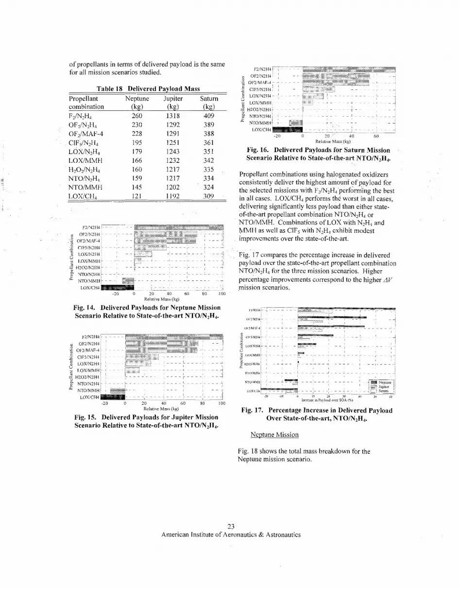
of propellants in terms of delivered payload is the same for all mission scenarios studied.
Table 18 Delivered Payload Mass Propellant Neptune Jupiter Saturn combination (kg) 0%) (kg) F2/N2H4 260 OFz/N>H4 230 OFz/MAF-4 228 CIF~/N~HI 195 LOiWN2H4 179 LOXiMMH 166 H202/'N2H4 I60 NTO/W?H4 159 NTOIMM ti 145 LOXICH4 121 --
1318 409 1292 3 89 1291 388 1251 361 1243 351 1232 342 1217 335 1217 334 1202 324 1192 309
L: OF2M2114
4 H202lN2H4
-20 0 20 40 60 80 100 Relative Mass (kg)
Fig. 14. Delivered Payloads for Neptune Mission Scenario Relative to State-of-the-art NTO/N2H4.
F2iN2H4 ' OF2!N2H4- 2 OF2IMAF-4
2 CIF5lN2H4- 5 LOWN2H4 2 L O U M M H - 2 H202iNZH4
N T O M ~ H ~ I
NTOllllMH LOXICH4
-20 0 20 40 60 80 100
F2iN2H4
E OF2IMM-4 2 ClF5h"2H4 - ~ ~
5 LOXIN2H4
OF2!N2H4 ~ ~
v LOXIMMH-
=" H2021N2H4 n 2 N 1 0 N 2 H 4
YTOIMMH LOXICH4
Relatibe Mas (Lg)
Fig. 16. Delivered Payloads for Saturn Mission Scenario Relative to State-of-the-art NTO/N2H4.
Propellant combinations using halogenated oxidizers consistently deliver the highest amount of,payload for the selected missions with F2/N2H4 performing the best in all cases. LOWCH4 performs the worst in all cases, delivering significantly less payload than either state- of-the-art propellant combination NTO/N2H4 or NTO/MMH. Combinations of LOX with N2H4 and MMH as well as ClF5 with NLH4 exhibit modest improvements over the state-of-the-art.
Fig. 17 compares the percentage increase in delivered payload over the state-of-the-art propellant combination NTO/N2H4 for the three mission scenarios. Higher percentage improvements correspond to the higher AV mission scenarios.
Fig. 17. Percentage Increase in Delivered Payload Relative Mass (kg)
Fig, 15. Delivered Payloads for Jupiter Mission Over State-of-the-art, NTO/N2H4. Scenario Relative to State-of-the-art NTO/N2H4.
Neptune Mission
Fig. 18 shows the total mass breakdown for the Neptune mission scenario.
23 American Institute of Aeronautics & Astronautics
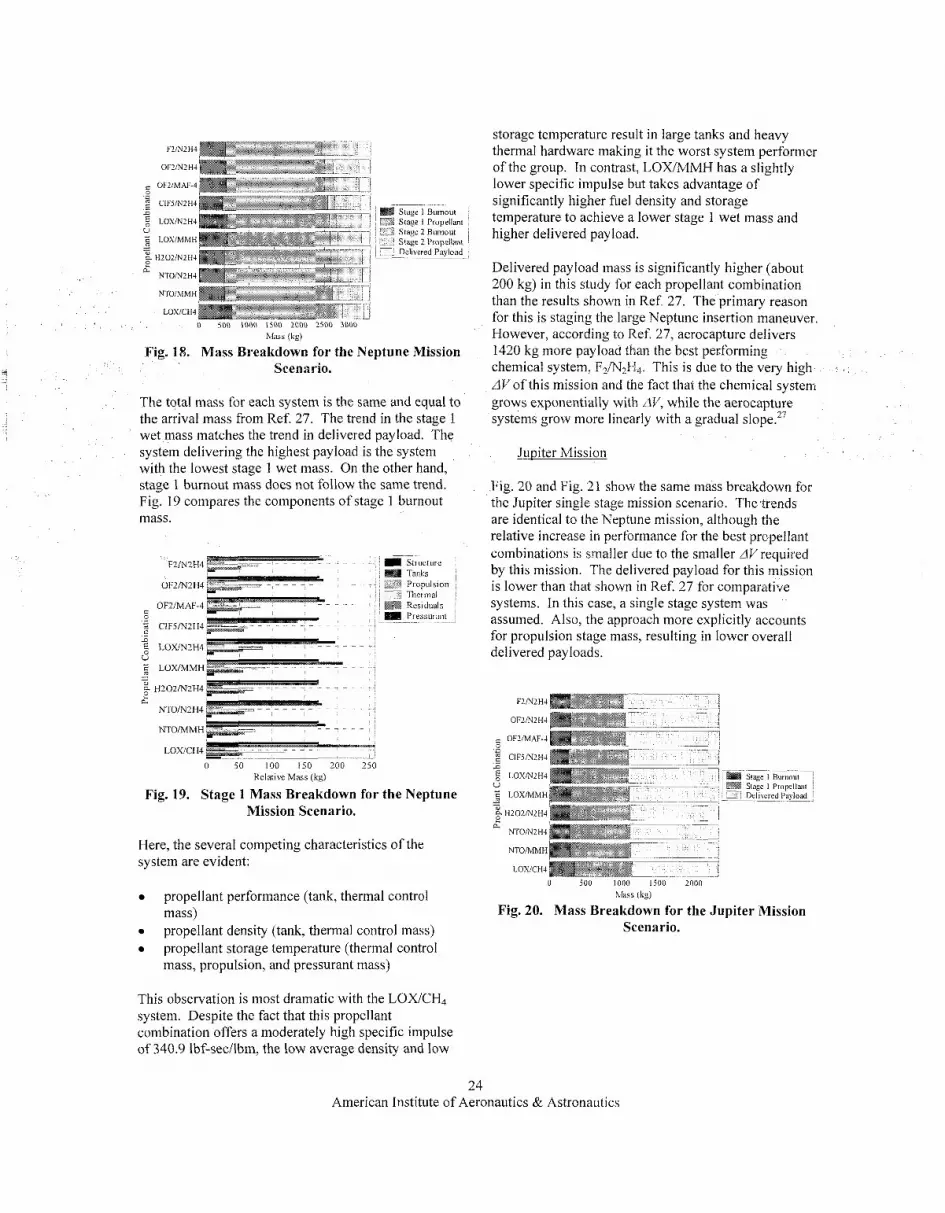
g LOYMZH4
~~ ~
Stage 1 Butaout
Stdgc 2 Bumout
Delivered ~~ Payload
stage 1 Propellant
stage 2 Propellant
0 i o 0 1000 1 ~ 0 0 LOOO 2>0O 3000 M&Ss (Lg)
Fig. 18. Mass Breakdown for the Neptune Mission Scenario.
The total mass for each system is the same and equal to the arrival mass from Ref. 27. The trend in the stage 1 wet mass matches the trend in delivered payload. The system delivering the highest payload is the system with the lowest stage 1 wet mass. On the other hand, stage I burnout maSs does not follow the same trend. Fig. 19 coinpares the components of stage 1 burnout mass.
0 50 100 150 200 250 Relative Mass (ks)
Fig. 19. Stage 1 Mass Breakdown for the Neptune Mission Scenario.
Here, the several competing characteristics of the system are evident:
propellant performance (tank, thermal control mass) propellant density (tank, thermal control mass) propellant storage temperature (thermal control mass, propulsion, and pressurant mass)
This observation is most dramatic with the LOX/CH4 system. Despite the fact that this propellant combination offers a moderately high specific impulse of 340.9 Ibf-secilbm, the low average density and low
storage temperature result in large tanks and heavy thermal hardware making it the worst system performer of the group. In contrast, LOX/MMH has a slightly lower specific impulse but takes advantage of significantly higher fuel density and storage temperature to achieve a lower stage 1 wet mass and higher delivered payload.
Delivered payload mass is significantly higher (about 200 kg) in this study for each propellant combination than the results shown in Ref 27. 'The primary reason for this is staging the large Neptune insertion maneuver. However, according to Ref. 27, aerocapture delivers 1420 kg more payload than the best pecforming chemical system, F2/?\J& This is due to the very high AV of this mission and the fact that the chemical system grows exponentially with AV, while the aerocapture systems grow more linearly with a gradual slope.27
- Jupiter Mission
Fig. 20 and Fig. 21 show the same mass breakdown for the Jupiter single stage mission scenario. The trends are identical to the Neptune mission, although the relative increase in performance for the best propellant combinations is smaller due to the smaller AVrequiied by this mission. The delivered payload for this mission is lower than that shown in Ref. 27 for comparative systems. In this case, a single stage system was assumed. Also, the approach more explicitly accounts for propulsion stage mass, resulting in lower overall delivered payloads.
OFZMLH4
OFZIMAF-4
2 CIFjNZH4 ~-~ n
LOXMLH4 S l a g I Burnaul U Stq!C I Propellail 5 LOXMMH DcIn~red ~ Pa&d
0
- - HZOZMLH4
NTOMZH4
NTO/MMH
LOXlCH4
c.
hlass (kg)
Fig. 20. Mass Breakdown for the Jupiter Mission Scenario.
24 American Institute of Aeronautics & Astronautics

F2fN2H4
OFZRi2H4
OFZIMAF-4 4 B CIF5IN2H4 5 5 LOXh’2114 U
LOWMMH
H202NZH4
N7OM2H4
NTO/MMH
D
- - e 0.
LOXITH~
0 20 40 60 80 100 Relatire M a s s (ks)
Fig. 21. Stage 1 Mass Breakdown for the Jupiter Mission Scenario.
Saturn Mission
Fig. 22 arid Fig. 23 show the mass breakdowns for the Saturn mission scenario. Once again, the trends are consistent with the trends in the other mission scenarios. The delivered payload for this mission scenario is slightly lower for the reference case, NTO/N2H4, than that shown in Ref. 27. This is again due lo the fact that stage mass has been more explicitly defined resulting in a heavier stage mass and lower payload inass than that calculated in Ref. 27.
LOXICH4 1311(1
blass (kg)
Fig. 22. Mass Breakdown for the Saturn Mission Scenario.
~
F2lN2 I14 Structure Tanks
‘Ihermal OF2fN2114 Propuls,on
OF2IMAF-4 R K S I ~ U ~ S 4 Pressurmt B C I F 5 W H 4
LOXW2H4 U 5 LOWMMH
E H202M2H4 2
NTOlNZH4
NTOIMMH
LOWCH4
~
a
- -
0 20 40 60 80 Relative Mass (kg)
Fig. 23. Stage 1 Mass Breakdown for the Saturn Mission Scenario.
Comparison to Figures of Merit
In the section “Propellant Combination Analysis”, several figures of merit were described for use in preliminary assessment of propellant combinations and propulsion systems using them. Table f 9 compares the ranking based on the Guernsey-Rapp FOM, limiting AV FOM, density specific impulse, and the actual system study dircussed in this section.
Table 19 Ranking of the Ten Propellant Combinations Considered in System Study by
Various Figures of Merit Propellant sys. Combination FOMGK FOMl,,, I , (I’ Study F z ~ ~ H J 1 1 1 1 OF2m2H4 3 3 4 2 OF,/MAF-4 2 2 3 3 ClF5/N?H4 7 4 2 4 LOX/NZH4 4 5 8 5 LOWMMH 5 8 9 6 H202m2H4 9 6 5 7 NTO/N2H4 8 7 6 8 NTO/MMH 10 9 7 9 LOXICH4 6 10 10 10
The limiting AVFOM appears to match the system study results the closest of the three figures of merit, despite the inaccurate application of c2 in its calculation (see “Propellant Combination Analysis”). The differences between the limiting AVFOM and the system study rankings are limited to switching of consecutive propellant combinations. Those combinations that are affected tended to yield payloads of approximately the same size. Therefore, the limiting AVFOM is shown to be reasonably accurate at
25 American Institute of Aeronautics & Astronautics

predicting relative system level performance between two propellant combinations.
The other FOMs do not appear to predict relative performance as accurately, although there are some interesting trends. All rankings show FZ/N2H4 to be the best performer. OF2/N2H4 and OF2/MAF-4 rank in the top four in all four FOMs used. LOX/N2H4 ranks in the top 5 in three of the four methods. LOX/CH4 ranks last in the group in three of the four methods used. A more comprehensive summary of data generated in this system study can be found in Ref. 10.
- CONCLUSIONS & RECOMMENDATIONS ~
The major conclusions drawn from the results presented in the rest of this paper are:
1 . Propellant conibinations iisingjhorinated oxidizers provided by far the largest improvenient in system performance (deJined in terms of delivered irsefiil payload mass) of any of the combinations studied. In particular, the combination of liquid fluorine oxidizer with hydrazine fuel provided the best performance. although other halogenated oxidizer and fuel combinations (such as OF,/MAF-4) could provide substantial performance iniprovements and have superior storability characteristics.
2. Passive storage ofpropellants at temperatzires as low as 120 K is,feasible using the existing state-of- the art in spacecraft thermal control Sunshades are required for this passive storage and will impose pointing constraints on the spacecraft. The attainable storage temperature is a very weak function of distance from the sun. Passive storage at temperatures as low as 80 K may be possible, but it likely to depend on exotic and unproven technologies.
3. Space storable chemical propulsion may offer signzjkant system benejts for missions using solar electric propulsion andor aerocaptzire technologies.
A Neptune Orbiter mission was studied which used solar electric propulsion in the inner solar system to provide a relatively fast transit time to Neptune, but relied on chemical propulsion for a very large (6.5 km/s) orbit insertion burn. The use of a space storable fluorine / hydrazine system could result in a 64% increase in zrsefiilpayload delivered compared to a state-of-the-art chemical propulsion
system. It must be noted that aerocapture technologies promise to offer even larger increases in delivered mass for this mission, but their feasibility and actual delivered performance are still undetermined.
A Saturn Orbiter mission that uses solar electric propulsion to provide for a fast transit was studied which had previously been shown to be enabled by the use of aerocapture for orbit insertion.27 However, a fairly large (3 .3 km/s) maneuver is required to raise the periapse to the desired orbit. The only propulsion technology available for this purpose is chemical propulsion. For this mission, it was found that the use oEa fluorine / hydrazine system could result in a 22% increase in iisefirlpayload when compared to the state-of-the-art.
We also examined a Jupiter Orbiter mission which had relatively modest (1.4 km/s) orbit insertion A V and which previous studies had shown little benefit to be obtained from the use of solar electric propulsion or aerocapt~ire .~~ For this mission, it was found that an 8% increase in iisefiripayload could be obtained through use of a space storable fluorine / hydrazine propulsioq system compared to the state-of-the-art.
In general, it was found that the potential mission benefit of space storable propulsion is highly dependent on the specific mission design. Mission designs which require higher A V from the chemical propulsion system show larger percentage increases in performance, but at the price of delivered payloads which may or may not be adequate to meet the science objectives of the mission. Further, it was noted that the mission designs which were adopted from Ref. 27 may not be representative of the mission designs that would in fact be selected for a mission based on the use of chemical propulsion in the outer solar system. For example, the highest delivered mass reported for the Saturn Orbiter mission in Ref. 27 was less than 500 kg, while the Cassini spacecraft is expected to deliver a useful payload of over 1500 kg when it enters Saturn orbit in 2004. Mission designs and trajectories providing similar performance might be found which could satisfy the science objectives of the Saturn mission studied here. Unfortunately, such mission design studies are well beyond the scope of the present effort.
The feasibility of developing space storable propulsion systems using halogenated oxidizers needs further study that could not be completed within the scope of this
26 American Institute of Aeronautics & Astronautics

task. Although numerous previous studies have concluded that these oxidizers can be handled safely, there has also been much skepticism expressed about this con~lusion.~” Indeed, when it was mandated that all US planetary missions would be launched on the Space Shuttle, the National Research Council issued it’s 198 1 report entitled “Liquid Rocket Propulsion Technology: An Evaluation of NASA’s Program”, which recommended against use of fluorinated oxidizers in the Space Shuttle, deeming it a “national asset”. This soon led to the termination of work on fluorinated propellants within NASA. However, based on NASA’s current plan to launch robotic missions using expendable launch vehicles, this conclusion is no longer relevant.
Fortunately, many of these safety and ground handling issues have been addressed in the l i t e r a t ~ r e . ~ , ~ ’ ~ Unfortunately, many of the personnel with first-hand experience are no longer available and few have recent experience
In addition to safety issues, there are fundamental reliability questions related to the fact that soft seal materials are not available for use with fluorinated oxidizers. Development of reliable metal-to-metal seals capable of large numbers ofcycles without leakage is a challenge that will require substantial expenditures. Fortunately, there has been substantial work done on basic material compatibility with fluorinated oxidizer^.^ Considerable component- and subsystem-level design work has also been p e r f ~ r m e d . ’ , ~ , ~
During this limited study, it was not possible to perform a complete literature search and evaluation of these issues, much less to bring together those remaining engineers with experience in halogenated oxidizers to assist in assessing the issues. This forms the basis of our first recommendation.
Recommendations
As a follow-on task, we recommend that a thorough literature search of the properties, handling practices, and safety of halogenated oxidizers be performed. In addition, one or more workshops should be held to bring together people with relevant experience in working with halogenated oxidizers. The objectives of this study would be a comprehensive assessment of the safety, technical, and cost issues associated with developing a space storable propulsion system.
The conclusion of the present study that passive storage below 120 K is a significant challenge is less optimistic that previous studies which concluded that storage temperatures as low as 80 K were attainable with
existing technol~gy.~~’ We recommend that further work be performed to understand this discrepancy and see if lower storage temperatures might indeed be attainable.
We also recommend:
The study of the potential for using hard cryogenic propellants with active cooling for deep space missions. Such a study is currently planned by the In-Space Propulsion Program.
A more thorough study of a spacecraft configuration and mission operational concept using SEP and passive cryogenic chemical stages to determine if the pointing constraints and thermal control assumptions in this report are feasible.
That a TDK kinetic reaction set for B5H9 be obtained from the literature so that the potential of this fuel can be more accurately assessed.
*
ACKNOWLEDGEMENTS
The authors thank Brian Reed (NASA Glenn Research Center) for lengthy discussions and information regarding nontoxic propellants, in particular HAN- Glycine and HAN-Methanol; Joe Lewis and Andre Yavorian (JPL) regarding propellant compatibility and the HEPS program; and Jeff Hall, Muriel Noca, and Robert Bailey (JPL) regarding their AIAA paper that is referenced many times in this paper and is the foundation upon which the mission section is based.
The work described in this paper was performed at the Jet Propulsion Laboratory, California Institute of Technology, under a contract to the National Aeronautics and Space Administration. This work was funded by the NASAiMarshall Space Flight Center (MSFC) In-Space Propulsion Program managed by Les Johnson (MSFC) with Rae Ann Meyer (MSFC) as the technical task manager.
REFERENCES
‘Bond, D., “Technology Status of a Fluorine-Hydrazine Propulsion System for Planetary Exploration,” AIAA Paper 79-0907, May 1979.
Propellant Modzile, Final Report, General Dynamics, Convair Division, GDC-BNZ 69-01 3-8, San Diego, CA, May 1970. 3 , Stzrdy of Safety Implications for Shztttle Launched Spacecraft Using Flztorinated Oxidizers,
2 , Prelaunch Operations for a Space Storable
27 American Institute of Aeronautics & Astronautics

Final Report, Volume I , TRW Systems Group, NAS 7- 100, Redondo Beach, CA, November 1975. ‘Schmidt, H., Handling and Use of a Fluorine and Fluorine-Oxygen ibzrxtures in Rocket Systems, NASA Lewis Research Center, NASA-SP-3037, Cleveland, OH, 1967. 5Toth, L., Moran, C., and Lewis, J., Materials Compatibility with Fluorine, Chemical Propulsion Information Agency (CPIA), CPIA Publication 296, Columbia, MD, March 1979. 6Appel, M., Progress on thp Developnient of L ip id Fluorine-Hydrazine Rocket Engine, Chemical Propulsion Information Agency (CPIA), CPIA Publication 296, Columbia, MD, March 1979. 7Weiner, R., Solis, C., and Hagler, R., Control Component Development for a Flirorriie-liydrazr~e Propzilsion System, Chemical Propulsion Information Agency (CPIA), CPIA Publication 296, Columbia, MD, March 1979. ‘Stultz, J., “Thermal Analysis of a High Energy Propulsion System for a Rover Class Mars Orbiter”, AIAA Paper 78-888, May 1978. 9Stultz, J., and Grippi, R., A Szrmmary and Update of the Conigzrrution and Temperature Control Studies for a Flziorinc-l-lvdrazine Propzrlsion Systems, Chemical Propulsion Information Agency (CPIA), CPIA Publication 206, Columbia, MD, March 1979. “Guernsey, C., Baker, R., Miyake, R., and Thunnissen, D., Space Storable Propzrlsion Advanced Chemical Proprlsion Final Report, Jet Propulsion Laboratory, JPL D-27810, Pasadena, CA, February 2004. “Reed, B., NASA Glenn Research Center, Cleveland, OH, e-mail correspondence (June - July 2003). “Kit, B. and Evered, D., Rocket Propellant Handbook, Macmillan Co., New York, NY, 1960. I3Sarner, S., Propellant Chemistry, Reinhold Publishing Corporation, New York, NY, 1966. “Marsh, W. and Knox, B., USAFPropellant Handbooks Hydrazine Fuels, Volzime 1, Bell Aerospace Company, AFRPL-TR-69-149, Buffalo, NY, March 1970.
pentafluoride”, Air Liquide Safety Datu Sheet [online database], URL: http://www.airliquide.com/safety/ msds/eni023-AL-EN.pdf [cited 16 November 20031. 16 , Rocket Engines and Propulsion Systems, Kaiser Marquardt, MP 7014, Van Nuys, CA, February 1995. I7Dunn, S., Coats, D., and Nickerson, G., TDK97, Tioo- Dimensional Kinetics (TDK) Nozzle Performance Conipziter Program, User ’s Manztal, Software & Engineering Associates, Inc., NAS8-39048, Carson City, NV, January 1998.
, “MSDS Nr: 023-AL - Chlorine 1s
“Gordon, S. and McBride, B., Conipirter Program for Calczrlation of Complex Chemical Eqztilibriztni Compositions nndilpplications Part 1 . Analysis, NASA Center for Aerospace Information, NASA-RP- 13 1 1, Hanover, MD, 1994. ‘gGuernsey, C. and Rapp, D., Propulsion Its Role in JPL Projects, the Status of Technology, and What We Need to Do in the Fzrtirre, Jet Propulsion Laboratory, D- 5617, Pasadena, CA, 8 August 1988.
Chazen, M. and Mueller, T., “A Summary of the Space Storable Rocket Technology Program,” AIAA Paper 95-2940, July 1995. 21 Wu, P., Woll, P, Stechniari, C., McLemore, B., Neiderman, J., and Crone, C., “Qualification Testing of a 2”d Generation High Performance Apogee Thruster’,” AIAA Paper 2001-3253, JUIY 2001, p. 1. 22Rattenni, L.. “Design and Performance of the Orbital Star-2 Propulsion Subsystem” AIAA Paper 2001-3394, July 2001, p. 12. "Cracker, A. and Peery, S., “System Sensitivity Studies of a LOWMethane Expander Cycle Rocket Engine,” AIAA Paper 98-3674, July 1998. “Zubrin, R., Frankie, B., Muscatello, T. , and Kito- Borsa, T., “Progress in the Development of Mars In- Situ Propellant Production System 0855, January 1999. 25 Pempie, P., Froehlich, T., and Vernin, H., “LOWMethane and LOWKerosene High Thrust Engine Trade-off,” AIAA Paper 2001-3542, July 2001.
Thunnissen, D., Rapp, D., Voorhees, C., Dawson, S., and Guernsey, C., “A 2007 Mars Sample Return Mission Utilizing In-Situ Propellant Production,” AIAA Paper 99-0851, January 1999.
Analysis of the Aerocapture Mission Set,” AIAA Paper
Mark, G., “Extreme Collaboration,” Communications of the ACM, Vol. 45, Issue 6, June 2002.
Dodge, B., “Beattie-Bridgeman Equation,” Chemical Engineering Thermodynamics, McGraw-Hill Company, New York, NY, 1944, pp. 183-186. 30 Yankura, G., and Appel, M., Proceedings of the Fluorine Handling Workshop, Jet Propulsion Laboratory (JPL), JPL D-567, Pasadena, CA, March 1983.
20
26
Hall, J., Noca, M., and Bailey, R., “Cost-Benefit 21
2003-4658, July 2003. 28
29
28 American Institute of Aeronautics & Astronautics