aca0862b and aca0862d: 1 ghz catv line amplifier mmic
TRANSCRIPT
Skyworks Solutions, Inc. • Phone [781] 376-3000 • Fax [781] 376-3100 • [email protected] • www.skyworksinc.com 204198D • Skyworks Proprietary Information • Products and Product Information are Subject to Change Without Notice • September 18, 2018 1
DATA SHEET
ACA0862B and ACA0862D: 1 GHz CATV Line Amplifier MMICApplications
50 to 1000 MHz 75 Ω amplifier
HFC distribution systems
CATV head-end equipment
CATV line amplifier
Features
1 GHz specified performance
Flat gain
Very low distortion
Excellent input/output match
Low DC power consumption
Good RF stability with high VSWR load conditions
Surface-mount package compatible with automatic assembly
Low cost
Repeatability of monolithic fabrication
Meets Cenelec standard
RoHS-compliant packaging
Skyworks GreenTM products are compliant with all applicable legislation and are halogen-free. For additional information, refer to Skyworks
Definition of GreenTM, document number SQ04-0074.
Description The ACA0862 family of surface-mount monolithic GaAs RF Linear Amplifiers has been developed to replace, in new designs, the standard CATV Hybrid amplifiers currently in use. The ACA0862 can also replace the ACA0861 with the addition of tuning capacitors to the output (see Figure 3). The MMICs consist of two parallel amplifiers, each with 12 dB gain. The amplifiers are optimized for exceptionally low distortion and noise figure while providing flat gain and excellent input and output return loss. The ACA0862B and ACA0862D are optimized for different output powers, and can be used separately or cascaded to support a variety of applications. A hybrid equivalent is formed when two ACA0862 devices are cascaded between transmission line baluns. For low-gain applications, a single ACA0862 can be used; for higher-gain applications, more than two can be cascaded. See the ACA0861 application note for more information.
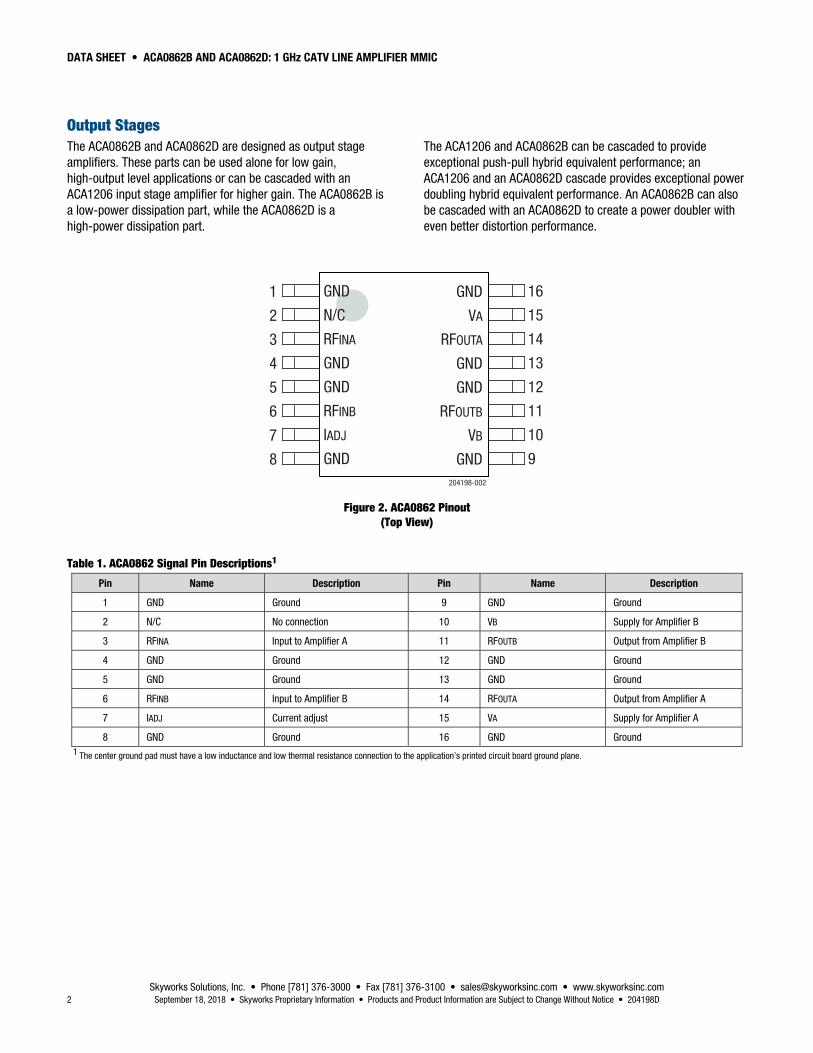
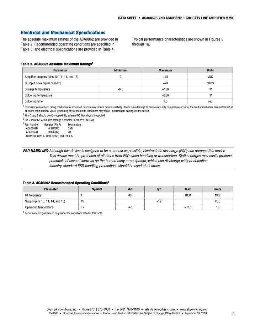
A block diagram of the ACA0862 is shown in Figure 1. The device package and pinout are shown in Figure 2. Signal pin assignments and functional pin descriptions are described in Table 1.
RF Input
15dB
15dB
RF Output
204198-001
12dB
12dB
ACA1206 ACA0862B/D
Figure 1. ACA0862 Block Diagram
DATA SHEET • ACA0862B AND ACA0862D: 1 GHz CATV LINE AMPLIFIER MMIC
Skyworks Solutions, Inc. • Phone [781] 376-3000 • Fax [781] 376-3100 • [email protected] • www.skyworksinc.com 2 September 18, 2018 • Skyworks Proprietary Information • Products and Product Information are Subject to Change Without Notice • 204198D
Output Stages The ACA0862B and ACA0862D are designed as output stage amplifiers. These parts can be used alone for low gain, high-output level applications or can be cascaded with an ACA1206 input stage amplifier for higher gain. The ACA0862B is a low-power dissipation part, while the ACA0862D is a high-power dissipation part.
The ACA1206 and ACA0862B can be cascaded to provide exceptional push-pull hybrid equivalent performance; an ACA1206 and an ACA0862D cascade provides exceptional power doubling hybrid equivalent performance. An ACA0862B can also be cascaded with an ACA0862D to create a power doubler with even better distortion performance.
1
2
3
4
5
6
7
8
16
15
14
13
12
11
10
9
GND
N/C
RFINA
GND
GND
RFINB
IADJ
GND
GND
VA
RFOUTA
GND
GND
RFOUTB
VB
GND204198-002
Figure 2. ACA0862 Pinout (Top View)
Table 1. ACA0862 Signal Pin Descriptions1
Pin Name Description Pin Name Description
1 GND Ground 9 GND Ground
2 N/C No connection 10 VB Supply for Amplifier B
3 RFINA Input to Amplifier A 11 RFOUTB Output from Amplifier B
4 GND Ground 12 GND Ground
5 GND Ground 13 GND Ground
6 RFINB Input to Amplifier B 14 RFOUTA Output from Amplifier A
7 IADJ Current adjust 15 VA Supply for Amplifier A
8 GND Ground 16 GND Ground 1 The center ground pad must have a low inductance and low thermal resistance connection to the application’s printed circuit board ground plane.
DATA SHEET • ACA0862B AND ACA0862D: 1 GHz CATV LINE AMPLIFIER MMIC
Skyworks Solutions, Inc. • Phone [781] 376-3000 • Fax [781] 376-3100 • [email protected] • www.skyworksinc.com 204198D • Skyworks Proprietary Information • Products and Product Information are Subject to Change Without Notice • September 18, 2018 3
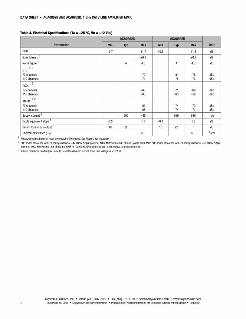
Electrical and Mechanical Specifications The absolute maximum ratings of the ACA0862 are provided in Table 2. Recommended operating conditions are specified in Table 3, and electrical specifications are provided in Table 4.
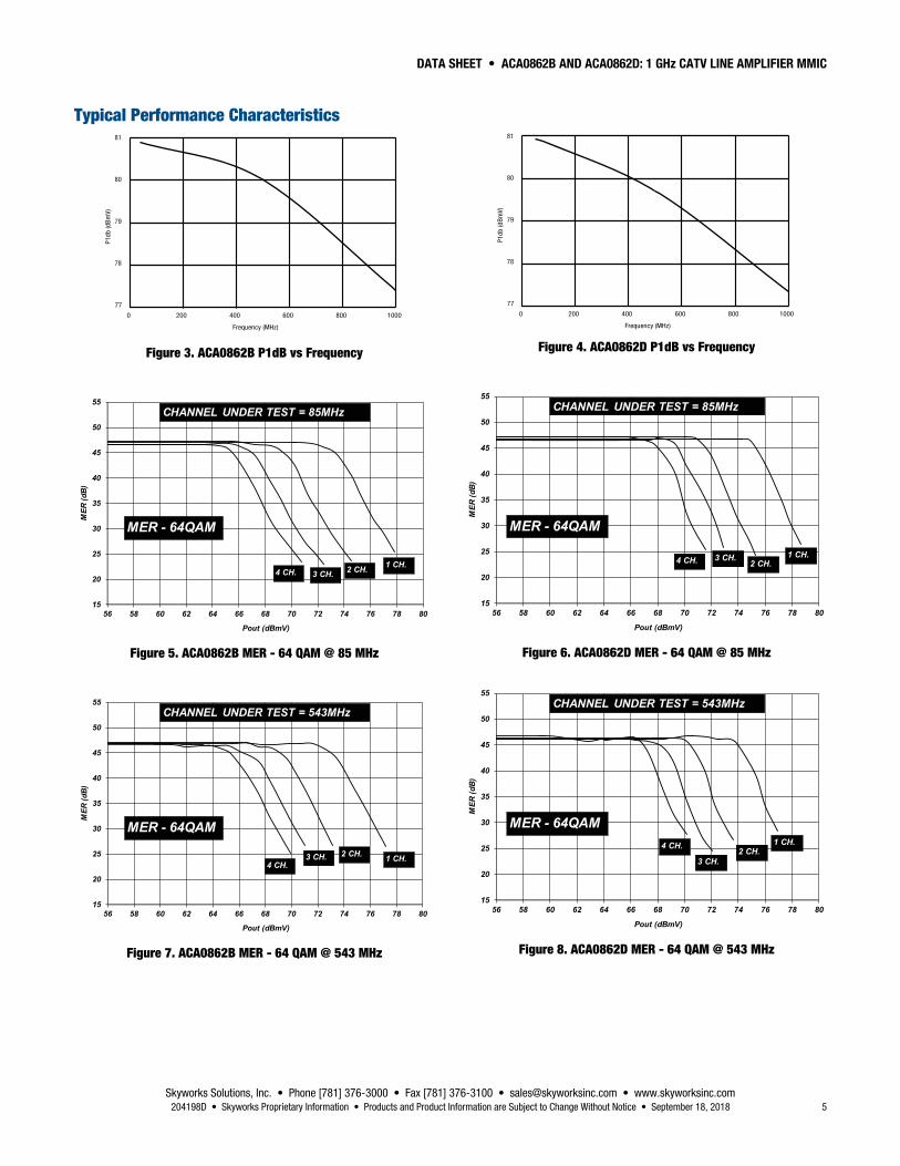
Typical performance characteristics are shown in Figures 3 through 16.
Table 2. ACA0862 Absolute Maximum Ratings1
Parameter Minimum Maximum Units
Amplifier supplies (pins 10, 11, 14, and 15) 0 +15 VDC
RF input power (pins 3 and 6) +70 dBmV
Storage temperature -6 5 +150 °C
Soldering temperature +260 °C
Soldering time 5.0 sec 1 Exposure to maximum rating conditions for extended periods may reduce device reliability. There is no damage to device with only one parameter set at the limit and all other parameters set at
or below their nominal value. Exceeding any of the limits listed here may result in permanent damage to the device. 2 Pins 3 and 6 should be AC-coupled. No external DC bias should be applied. 3 Pin 7 must be terminated through a resistor to either VD or GND: 4 Part Number Resistor (Pin 7) Termination
ACA0862B 4.32K(R1) GND ACA0862D 9.09K(R2) VD Refer to Figure 17 (test circuit) and Table 6.
ESD HANDLING: Although this device is designed to be as robust as possible, electrostatic discharge (ESD) can damage this device.
This device must be protected at all times from ESD when handling or transporting. Static charges may easily produce
potentials of several kilovolts on the human body or equipment, which can discharge without detection.
Industry-standard ESD handling precautions should be used at all times.
Table 3. ACA0862 Recommended Operating Conditions1
Parameter Symbol Min Typ Max Units
RF frequency f 40 1000 MHz
Supply (pins 10, 11, 14, and 15) VD +12 VDC
Operating temperature TA -40 +110 °C 1 Performance is guaranteed only under the conditions listed in this table.
DATA SHEET • ACA0862B AND ACA0862D: 1 GHz CATV LINE AMPLIFIER MMIC
Skyworks Solutions, Inc. • Phone [781] 376-3000 • Fax [781] 376-3100 • [email protected] • www.skyworksinc.com 4 September 18, 2018 • Skyworks Proprietary Information • Products and Product Information are Subject to Change Without Notice • 204198D
Table 4. Electrical Specifications (TA = +25 °C, VD = +12 VDC)
Parameter
ACA0862B ACA0862D
Unit Min Typ Max Min Typ Max
Gain 1 10.7 11.7 10.8 11.8 dB
Gain flatness 1 ±0.3 ±0.3 dB
Noise figure 1 4 4.5 4 4.5 dB
CTB: 1, 2
77 channels 110 channels
-70 -71
-81 -76
-78 -73
dBc dBc
CSO: 1, 2
77 channels 110 channels
-68 -66
-71 -63
-68 -56
dBc dBc
XMOD: 1, 2
77 channels 110 channels
-65 -68
-74 -74
-72 -71
dBc dBc
Supply current 3 395 445 530 610 mA
Cable equivalent slope 1 -0.5 1.0 -0.5 1.0 dB
Return loss (input/output) 1 18 22 18 22 dB
Thermal resistance (θJC) 6.0 6.0 OC/W 1 Measured with a balun on input and output of the device. See Figure 3 for test setup. 2 “B” device measured with 79 analog channels, +47 dBmV output power at 1002 MHz with a 3 dB tilt and QAM to 1002 MHz. “D” device measured with 79 analog channels, +56 dBmV output
power at 1002 MHz with a 15.6 dB tilt and QAM to 1002 MHz. QAM channels are -6 dB relative to analog channels. 3 A fixed resistor is needed (see Table 6) to set the devices’ current draw. Bias voltage is +12 VDC.
DATA SHEET • ACA0862B AND ACA0862D: 1 GHz CATV LINE AMPLIFIER MMIC
Skyworks Solutions, Inc. • Phone [781] 376-3000 • Fax [781] 376-3100 • [email protected] • www.skyworksinc.com 204198D • Skyworks Proprietary Information • Products and Product Information are Subject to Change Without Notice • September 18, 2018 5
Typical Performance Characteristics P1
db (d
Bm
V)
81
80
79
78
77 0 200 400 600 800 1000
Frequency (MHz)
Figure 3. ACA0862B P1dB vs Frequency
15
20
25
30
35
40
45
50
55
56 58 60 62 64 66 68 70 72 74 76 78 80
MER
(dB
)
Pout (dBmV)
CHANNEL UNDER TEST = 85MHz
MER - 64QAM
4 CH. 3 CH. 2 CH. 1 CH.
Figure 5. ACA0862B MER - 64 QAM @ 85 MHz
15
20
25
30
35
40
45
50
55
56 58 60 62 64 66 68 70 72 74 76 78 80
MER
(dB
)
Pout (dBmV)
CHANNEL UNDER TEST = 543MHz
MER - 64QAM
4 CH.3 CH. 2 CH. 1 CH.
Figure 7. ACA0862B MER - 64 QAM @ 543 MHz
P1db
(dB
mV)
81
80
79
78
77 0 200 400 600 800 1000
Frequency (MHz)
Figure 4. ACA0862D P1dB vs Frequency
15
20
25
30
35
40
45
50
55
56 58 60 62 64 66 68 70 72 74 76 78 80
MER
(dB
)
Pout (dBmV)
CHANNEL UNDER TEST = 85MHz
MER - 64QAM
4 CH. 3 CH.2 CH.
1 CH.
Figure 6. ACA0862D MER - 64 QAM @ 85 MHz
15
20
25
30
35
40
45
50
55
56 58 60 62 64 66 68 70 72 74 76 78 80
MER
(dB
)
Pout (dBmV)
CHANNEL UNDER TEST = 543MHz
MER - 64QAM4 CH.
3 CH.2 CH.
1 CH.
Figure 8. ACA0862D MER - 64 QAM @ 543 MHz
DATA SHEET • ACA0862B AND ACA0862D: 1 GHz CATV LINE AMPLIFIER MMIC
Skyworks Solutions, Inc. • Phone [781] 376-3000 • Fax [781] 376-3100 • [email protected] • www.skyworksinc.com 6 September 18, 2018 • Skyworks Proprietary Information • Products and Product Information are Subject to Change Without Notice • 204198D
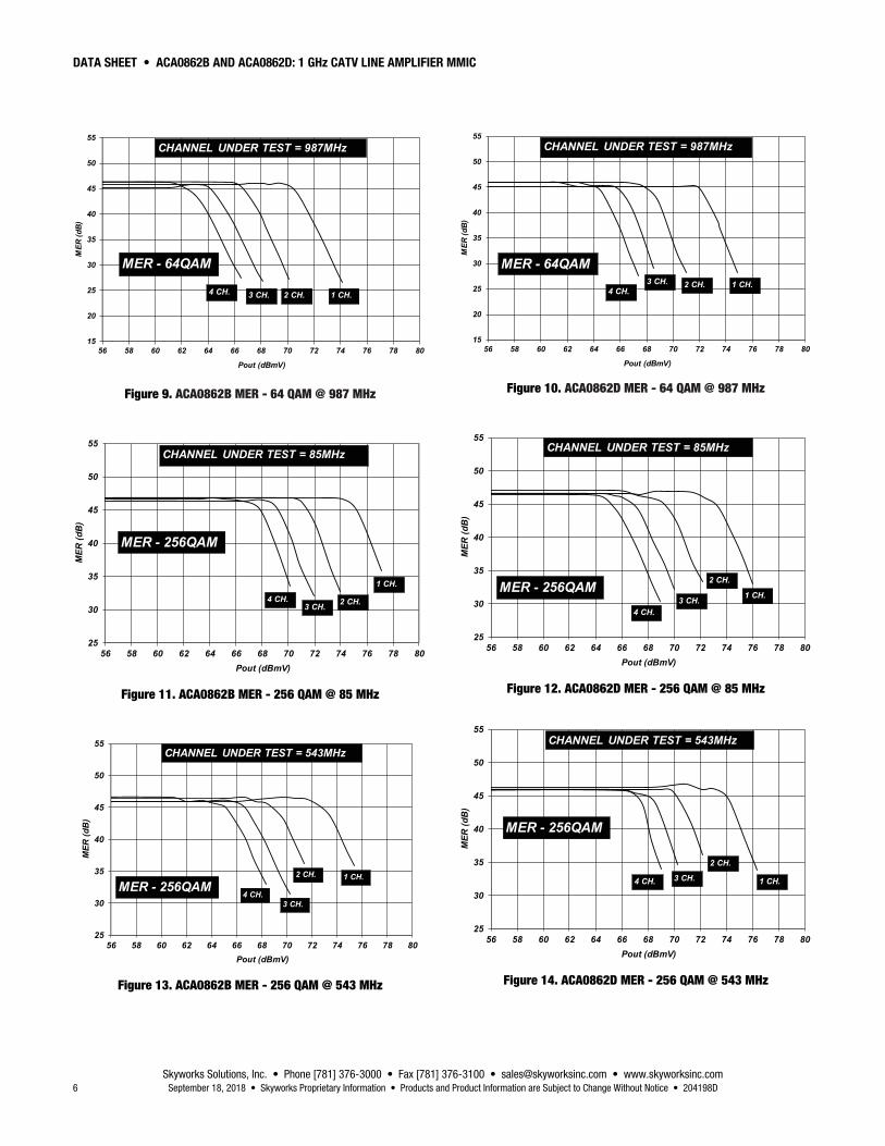
15
20
25
30
35
40
45
50
55
56 58 60 62 64 66 68 70 72 74 76 78 80
MER
(dB
)
Pout (dBmV)
CHANNEL UNDER TEST = 987MHz
MER - 64QAM
4 CH. 3 CH. 2 CH. 1 CH.
Figure 9. ACA0862B MER - 64 QAM @ 987 MHz
25
30
35
40
45
50
55
56 58 60 62 64 66 68 70 72 74 76 78 80
MER
(dB
)
Pout (dBmV)
CHANNEL UNDER TEST = 85MHz
MER - 256QAM
4 CH.3 CH. 2 CH.
1 CH.
Figure 11. ACA0862B MER - 256 QAM @ 85 MHz
25
30
35
40
45
50
55
56 58 60 62 64 66 68 70 72 74 76 78 80
MER
(dB
)
Pout (dBmV)
CHANNEL UNDER TEST = 543MHz
MER - 256QAM4 CH.
3 CH.
2 CH. 1 CH.
Figure 13. ACA0862B MER - 256 QAM @ 543 MHz
15
20
25
30
35
40
45
50
55
56 58 60 62 64 66 68 70 72 74 76 78 80
MER
(dB
)
Pout (dBmV)
CHANNEL UNDER TEST = 987MHz
MER - 64QAM
4 CH.3 CH. 2 CH. 1 CH.
Figure 10. ACA0862D MER - 64 QAM @ 987 MHz
25
30
35
40
45
50
55
56 58 60 62 64 66 68 70 72 74 76 78 80
MER
(dB
)
Pout (dBmV)
CHANNEL UNDER TEST = 85MHz
MER - 256QAM4 CH.
3 CH.
2 CH.
1 CH.
Figure 12. ACA0862D MER - 256 QAM @ 85 MHz
25
30
35
40
45
50
55
56 58 60 62 64 66 68 70 72 74 76 78 80
MER
(dB
)
Pout (dBmV)
CHANNEL UNDER TEST = 543MHz
MER - 256QAM
3 CH.
2 CH.
1 CH.4 CH.
Figure 14. ACA0862D MER - 256 QAM @ 543 MHz
DATA SHEET • ACA0862B AND ACA0862D: 1 GHz CATV LINE AMPLIFIER MMIC
Skyworks Solutions, Inc. • Phone [781] 376-3000 • Fax [781] 376-3100 • [email protected] • www.skyworksinc.com 204198D • Skyworks Proprietary Information • Products and Product Information are Subject to Change Without Notice • September 18, 2018 7
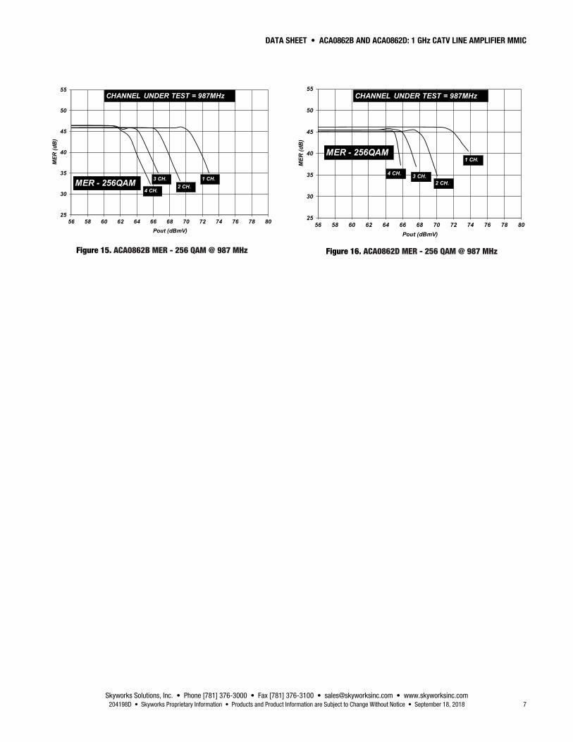
25
30
35
40
45
50
55
56 58 60 62 64 66 68 70 72 74 76 78 80
MER
(dB
)
Pout (dBmV)
CHANNEL UNDER TEST = 987MHz
MER - 256QAM4 CH.
3 CH.2 CH.
1 CH.
Figure 15. ACA0862B MER - 256 QAM @ 987 MHz
25
30
35
40
45
50
55
56 58 60 62 64 66 68 70 72 74 76 78 80
MER
(dB
)
Pout (dBmV)
CHANNEL UNDER TEST = 987MHz
MER - 256QAM
3 CH.2 CH.
1 CH.
4 CH.
Figure 16. ACA0862D MER - 256 QAM @ 987 MHz
DATA SHEET • ACA0862B AND ACA0862D: 1 GHz CATV LINE AMPLIFIER MMIC
Skyworks Solutions, Inc. • Phone [781] 376-3000 • Fax [781] 376-3100 • [email protected] • www.skyworksinc.com 8 September 18, 2018 • Skyworks Proprietary Information • Products and Product Information are Subject to Change Without Notice • 204198D
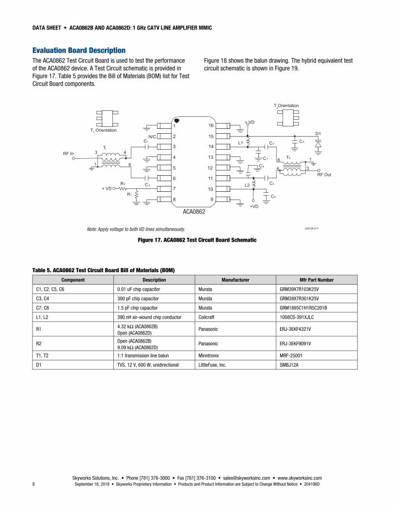
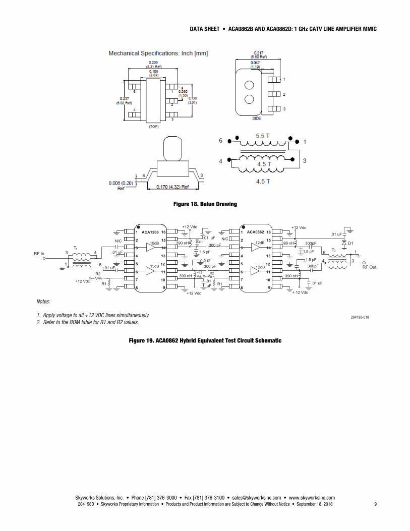
Evaluation Board Description The ACA0862 Test Circuit Board is used to test the performance of the ACA0862 device. A Test Circuit schematic is provided in Figure 17. Table 5 provides the Bill of Materials (BOM) list for Test Circuit Board components.
Figure 18 shows the balun drawing. The hybrid equivalent test circuit schematic is shown in Figure 19.
1
2
3
4
5
6
7
8 9
10
11
12
13
14
15
16
N/C
R1
+VD
L2
+ VD
RF In
RF Out
L1T1
T2
C1
C2C4
C3
C6
C5
C7
R2
+ VD
C81
3
6
4
1
3
6
4
T1 Orientation
T2Orientation
204198-017
D1
ACA0862
Note: Apply voltage to both VD lines simultaneously.
Figure 17. ACA0862 Test Circuit Board Schematic
Table 5. ACA0862 Test Circuit Board Bill of Materials (BOM)
Component Description Manufacturer Mfr Part Number
C1, C2, C5, C6 0.01 uF chip capacitor Murata GRM39X7R103K25V
C3, C4 300 pF chip capacitor Murata GRM39X7R301K25V
C7, C8 1.5 pF chip capacitor Murata GRM1885C1H1R5C201B
L1, L2 390 nH air-wound chip conductor Coilcraft 1008CS-391XJLC
R1 4.32 kΩ(ACA0862B) Open (ACA0862D)
Panasonic ERJ-3EKF4321V
R2 Open(ACA0862B) 9.09 kΩ (ACA0862D)
Panasonic ERJ-3EKF9091V
T1, T2 1:1 transmission line balun Minntronix MRF-25001
D1 TVS, 12 V, 600 W, unidirectional LittleFuse, Inc. SMBJ12A
DATA SHEET • ACA0862B AND ACA0862D: 1 GHz CATV LINE AMPLIFIER MMIC
Skyworks Solutions, Inc. • Phone [781] 376-3000 • Fax [781] 376-3100 • [email protected] • www.skyworksinc.com 204198D • Skyworks Proprietary Information • Products and Product Information are Subject to Change Without Notice • September 18, 2018 9
Figure 18. Balun Drawing
ACA1206 ACA0862
R2
+12 Vdc
1.5 pF
1.5 pF 1.5 pF
1.5 pF
+12Vdc
R2
15dB
15dB
RF In
RF Out
T1 T2
1
3
6
4 1
3
6
4
D1D1
Notes:
1. Apply voltage to all +12 VDC lines simultaneously.
2. Refer to the BOM table for R1 and R2 values.204198-018
Figure 19. ACA0862 Hybrid Equivalent Test Circuit Schematic
DATA SHEET • ACA0862B AND ACA0862D: 1 GHz CATV LINE AMPLIFIER MMIC
Skyworks Solutions, Inc. • Phone [781] 376-3000 • Fax [781] 376-3100 • [email protected] • www.skyworksinc.com 10 September 18, 2018 • Skyworks Proprietary Information • Products and Product Information are Subject to Change Without Notice • 204198D
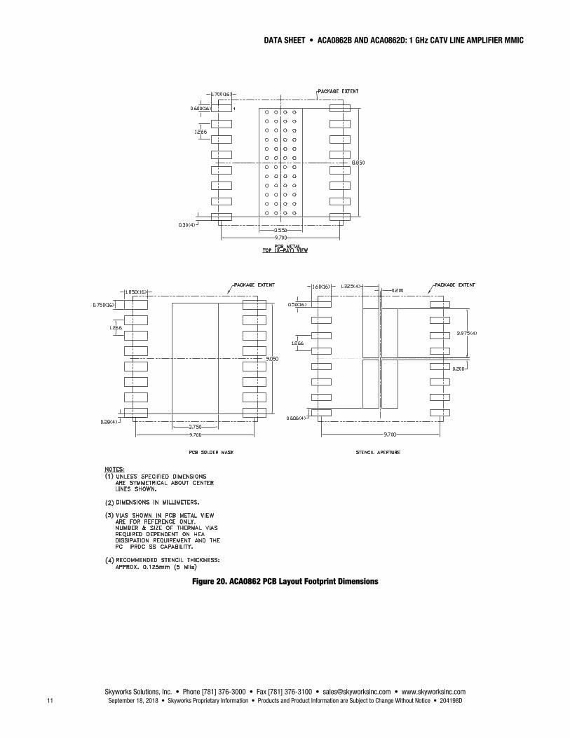
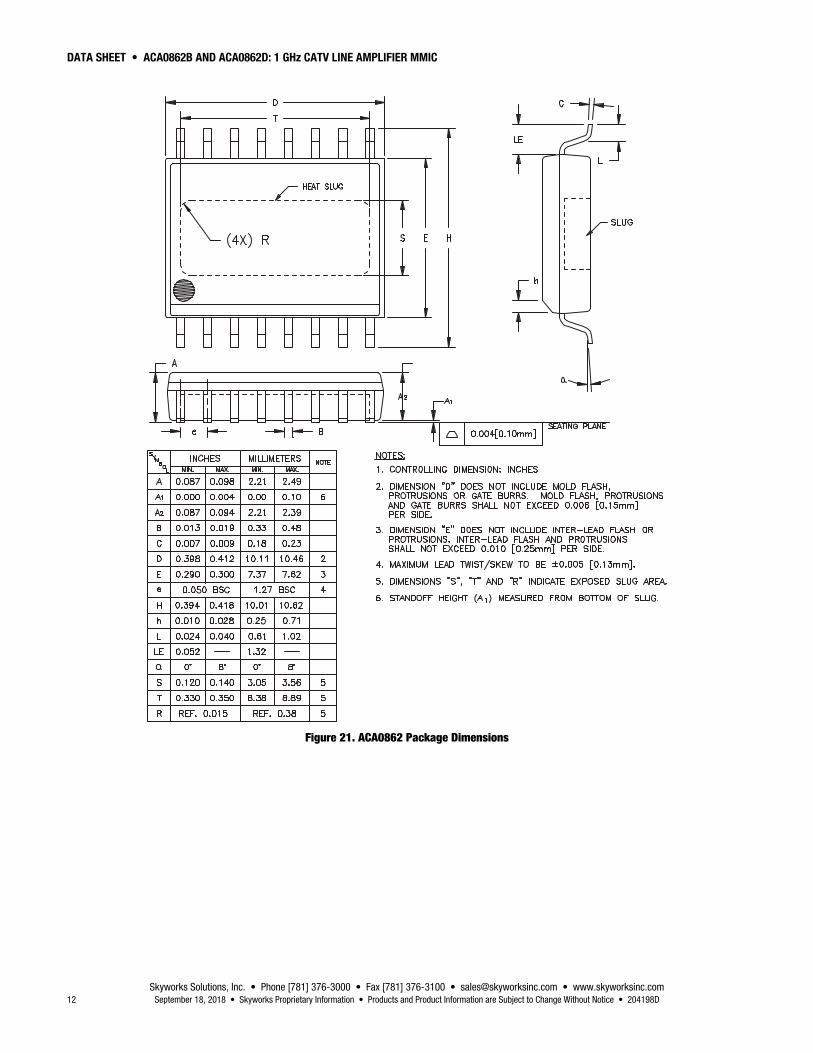
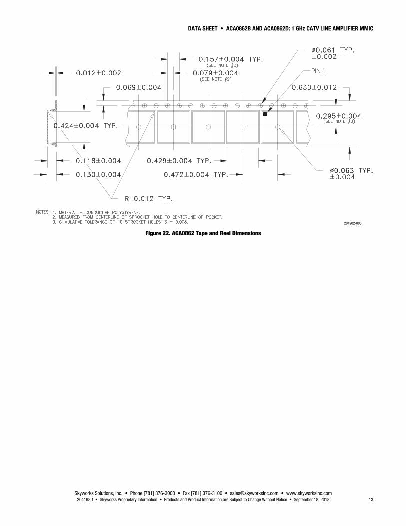
Package Dimensions The PCB layout footprint drawing for the ACA0862 is shown in Figure 20. The package dimensions for the ACA0862 are shown in Figure 21. The tape and reel dimensions are provided in Figure 22.
Package and Handling Information Since the device package is sensitive to moisture absorption, it is baked and vacuum packed before shipping. Instructions on the shipping container label regarding exposure to moisture after the container seal is broken must be followed. Otherwise, problems related to moisture absorption may occur when the part is subjected to high temperature during solder assembly.
The ACA0862 is rated to Moisture Sensitivity Level 2 (MSL2) at 260 C. It can be used for lead or lead-free soldering. For additional information, refer to the Skyworks Application Note, Solder Reflow Information, document number 200164.
Care must be taken when attaching this product, whether it is done manually or in a production solder reflow environment. Production quantities of this product are shipped in a standard tape and reel format.
DATA SHEET • ACA0862B AND ACA0862D: 1 GHz CATV LINE AMPLIFIER MMIC
Skyworks Solutions, Inc. • Phone [781] 376-3000 • Fax [781] 376-3100 • [email protected] • www.skyworksinc.com 11 September 18, 2018 • Skyworks Proprietary Information • Products and Product Information are Subject to Change Without Notice • 204198D
Figure 20. ACA0862 PCB Layout Footprint Dimensions
DATA SHEET • ACA0862B AND ACA0862D: 1 GHz CATV LINE AMPLIFIER MMIC
Skyworks Solutions, Inc. • Phone [781] 376-3000 • Fax [781] 376-3100 • [email protected] • www.skyworksinc.com 12 September 18, 2018 • Skyworks Proprietary Information • Products and Product Information are Subject to Change Without Notice • 204198D
Figure 21. ACA0862 Package Dimensions
DATA SHEET • ACA0862B AND ACA0862D: 1 GHz CATV LINE AMPLIFIER MMIC
Skyworks Solutions, Inc. • Phone [781] 376-3000 • Fax [781] 376-3100 • [email protected] • www.skyworksinc.com 204198D • Skyworks Proprietary Information • Products and Product Information are Subject to Change Without Notice • September 18, 2018 13
204202-006
Figure 22. ACA0862 Tape and Reel Dimensions
DATA SHEET • ACA0862B AND ACA0862D: 1 GHz CATV LINE AMPLIFIER MMIC
Skyworks Solutions, Inc. • Phone [781] 376-3000 • Fax [781] 376-3100 • [email protected] • www.skyworksinc.com 14 September 18, 2018 • Skyworks Proprietary Information • Products and Product Information are Subject to Change Without Notice • 204198D
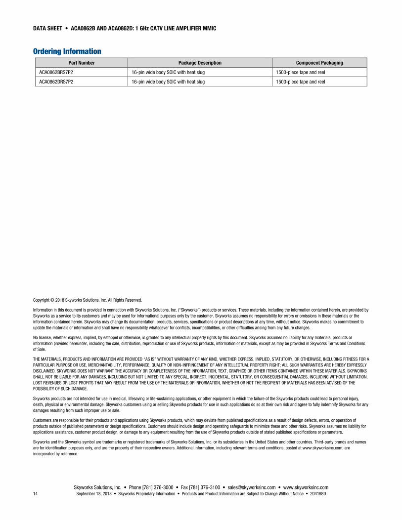
Ordering Information Part Number Package Description Component Packaging
ACA0862BRS7P2 16-pin wide body SOIC with heat slug 1500-piece tape and reel
ACA0862DRS7P2 16-pin wide body SOIC with heat slug 1500-piece tape and reel
Copyright © 2018 Skyworks Solutions, Inc. All Rights Reserved.
Information in this document is provided in connection with Skyworks Solutions, Inc. (“Skyworks”) products or services. These materials, including the information contained herein, are provided by Skyworks as a service to its customers and may be used for informational purposes only by the customer. Skyworks assumes no responsibility for errors or omissions in these materials or the information contained herein. Skyworks may change its documentation, products, services, specifications or product descriptions at any time, without notice. Skyworks makes no commitment to update the materials or information and shall have no responsibility whatsoever for conflicts, incompatibilities, or other difficulties arising from any future changes.
No license, whether express, implied, by estoppel or otherwise, is granted to any intellectual property rights by this document. Skyworks assumes no liability for any materials, products or information provided hereunder, including the sale, distribution, reproduction or use of Skyworks products, information or materials, except as may be provided in Skyworks Terms and Conditions of Sale.
THE MATERIALS, PRODUCTS AND INFORMATION ARE PROVIDED “AS IS” WITHOUT WARRANTY OF ANY KIND, WHETHER EXPRESS, IMPLIED, STATUTORY, OR OTHERWISE, INCLUDING FITNESS FOR A PARTICULAR PURPOSE OR USE, MERCHANTABILITY, PERFORMANCE, QUALITY OR NON-INFRINGEMENT OF ANY INTELLECTUAL PROPERTY RIGHT; ALL SUCH WARRANTIES ARE HEREBY EXPRESSLY DISCLAIMED. SKYWORKS DOES NOT WARRANT THE ACCURACY OR COMPLETENESS OF THE INFORMATION, TEXT, GRAPHICS OR OTHER ITEMS CONTAINED WITHIN THESE MATERIALS. SKYWORKS SHALL NOT BE LIABLE FOR ANY DAMAGES, INCLUDING BUT NOT LIMITED TO ANY SPECIAL, INDIRECT, INCIDENTAL, STATUTORY, OR CONSEQUENTIAL DAMAGES, INCLUDING WITHOUT LIMITATION, LOST REVENUES OR LOST PROFITS THAT MAY RESULT FROM THE USE OF THE MATERIALS OR INFORMATION, WHETHER OR NOT THE RECIPIENT OF MATERIALS HAS BEEN ADVISED OF THE POSSIBILITY OF SUCH DAMAGE.
Skyworks products are not intended for use in medical, lifesaving or life-sustaining applications, or other equipment in which the failure of the Skyworks products could lead to personal injury, death, physical or environmental damage. Skyworks customers using or selling Skyworks products for use in such applications do so at their own risk and agree to fully indemnify Skyworks for any damages resulting from such improper use or sale.
Customers are responsible for their products and applications using Skyworks products, which may deviate from published specifications as a result of design defects, errors, or operation of products outside of published parameters or design specifications. Customers should include design and operating safeguards to minimize these and other risks. Skyworks assumes no liability for applications assistance, customer product design, or damage to any equipment resulting from the use of Skyworks products outside of stated published specifications or parameters.
Skyworks and the Skyworks symbol are trademarks or registered trademarks of Skyworks Solutions, Inc. or its subsidiaries in the United States and other countries. Third-party brands and names are for identification purposes only, and are the property of their respective owners. Additional information, including relevant terms and conditions, posted at www.skyworksinc.com, are incorporated by reference.