a systems architecting methodology using bloom's
TRANSCRIPT
978-1-5386-2014-4/18/$31.00 ©2018 IEEE 1
A Systems Architecting Methodology Using Bloom’s
Taxonomy to Promote Creative Engineering Synthesis Paulo Younse, Jackson W. Strahle, Karan Lalla,
Marco Dolci, Preston Ohta, Rama Adajian Jet Propulsion Laboratory
California Institute of Technology Pasadena, CA 91109 USA
Abstract—Architecting complex systems requires high-level
cognitive processing and extensive knowledge of the system
elements, functions, relationships, and constraints. This paper
describes a systems architecting methodology implemented
through cognitive psychological creative processes using
Bloom’s taxonomy as a framework to generate the expert
knowledge required to effectively and systematically synthesize
new systems. Systems architecting activities were carried out to
identify, develop, and capture factual and conceptual
knowledge relevant to the system subject matter and functional
elements, as well as to facilitate active processing of the
knowledge through remembering, understanding, applying,
analyzing, evaluating, and creating. Dual channel and limited
capacity principles of learning were incorporated into the
format of the systems engineering tools developed to assist with
information processing and retention. Metacognitive strategies
associated with memory and creative idea generation were
implemented into the methodology to effectively and efficiently
develop system alternatives using the full collection of
knowledge. Synthesis of an orbiting sample capture and
orientation system architecture to enable spacecraft-based on-
orbit capture of a Mars sample container for a potential Mars
Sample Return campaign was used as a case study.
TABLE OF CONTENTS
1. INTRODUCTION ....................................................... 1 2. BACKGROUND ......................................................... 2 3. SYSTEMS ARCHITECTING APPROACH .................. 6 4. SYSTEMS ARCHITECTING TOOLS .......................... 8 5. SYSTEMS ARCHITECTING METHODOLOGY ........ 18 6. CASE STUDY .......................................................... 20 7. FUTURE WORK ..................................................... 20 8. SUMMARY ............................................................. 21 ACKNOWLEDGEMENTS ............................................ 21 REFERENCES............................................................. 21 BIOGRAPHY .............................................................. 23
1. INTRODUCTION
Modern engineering systems are rapidly becoming
increasingly complex due to the development of new
emerging technologies and the integration of elements that
span multiple knowledge domains. Architecting new and
effective systems with these attributes can require both a
high level of creativity and a deep knowledge base
stemming from multiple domains. Creativity within the field
of engineering is typically implemented through idea
generation processes and methodologies [1], [2], [3],
variations in brainstorming techniques [4], [5], and varieties
of algorithms and tools such as TRIZ [6]. Acquiring
knowledge is typically accomplished through securing
domain experts, spending time gaining experience,
conducting literature review (e.g., utility and design
patents), and reverse engineering (i.e. functional
decomposition) of existing systems [7].
This paper aims to supplement these approaches and
improve their effectiveness by structuring a methodology
that further promotes creative engineering synthesis for
architecting complex systems using a cognitive
psychological approach based on current theories and
principles of creativity, human cognition, and education,
complimented with tools and techniques drawn from
systems engineering. A strong focus of this research is on
the education aspect, recognizing that expert domain
knowledge is a key component of creativity and that
incorporation of learning activities structured around
Bloom’s Taxonomy (a framework used by educators that
classifies knowledge and cognitive processes) can assist
with effectively acquiring necessary domain knowledge.
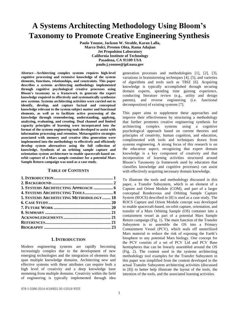
To illustrate the tools and methodology discussed in this
paper, a Transfer Subsystem, which is an element of a
Capture and Orient Module (COM), and part of a larger
conceptual Rendezvous and Orbiting Sample Capture
System (ROCS) described in [8] is used as a case study. The
ROCS Capture and Orient Module concept was developed
to enable spacecraft-based, on-orbit capture, orientation, and
transfer of a Mars Orbiting Sample (OS) container into a
containment vessel as part of a potential Mars Sample
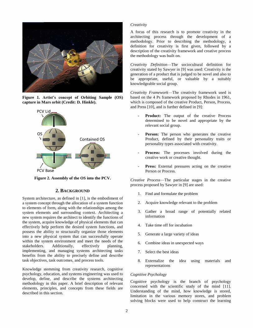
Return campaign (Fig. 1). The main function of the Transfer
Subsystem is to assemble the OS into a Primary
Containment Vessel (PCV), which seals off unsterilized
Mars material to reduce the risk of exposing the Earth’s
biosphere to any potential Mars biology. One concept for
the PCV consists of a set of PCV Lid and PCV Base
hemispheres that can be linearly assembled around the OS
(Fig. 2). The content used in the systems architecting
methodology tool examples for the Transfer Subsystem in
this paper was simplified from the content developed in the
actual Transfer Subsystem architecting activities (discussed
in [8]) to better help illustrate the layout of the tools, the
intention of the tools, and the associated learning activities.
2
Figure 1. Artist’s concept of Orbiting Sample (OS)
capture in Mars orbit (Credit: D. Hinkle).
Figure 2. Assembly of the OS into the PCV.
2. BACKGROUND
System architecture, as defined in [1], is the embodiment of
a system concept through the allocation of a system function
to elements of form, along with the relationships among the
system elements and surrounding context. Architecting a
new system requires the architect to identify the functions of
the system, acquire knowledge of physical elements that can
effectively help perform the desired system functions, and
possess the ability to structurally organize those elements
into a new physical system that can successfully operate
within the system environment and meet the needs of the
stakeholders. Additionally, effectively planning,
implementing, and managing systems architecting tasks
benefits from the ability to precisely define and describe
task objectives, task outcomes, and process tools.
Knowledge stemming from creativity research, cognitive
psychology, education, and systems engineering was used to
develop, define, and describe the systems architecting
methodology in this paper. A brief description of relevant
elements, principles, and concepts from these fields are
described in this section.
Creativity
A focus of this research is to promote creativity in the
architecting process through the development of a
methodology. Prior to describing the methodology, a
definition for creativity is first given, followed by a
description of the creativity framework and creative process
the methodology was built on.
Creativity Definition—The sociocultural definition for
creativity stated by Sawyer in [9] was used: Creativity is the
generation of a product that is judged to be novel and also to
be appropriate, useful, or valuable by a suitably
knowledgeable social group.
Creativity Framework—The creativity framework used is
based on the 4 Ps framework proposed by Rhodes in 1961,
which is composed of the creative Product, Person, Process,
and Press [10], and is further defined in [9]:
- Product: The output of the creative Process
determined to be novel and appropriate by the
relevant social group.
- Person: The person who generates the creative
Product, defined by their personality traits or
personality types associated with creativity.
- Process: The processes involved during the
creative work or creative thought.
- Press: External pressures acting on the creative
Person or Process.
Creative Process—The particular stages in the creative
process proposed by Sawyer in [9] are used:
1. Find and formulate the problem
2. Acquire knowledge relevant to the problem
3. Gather a broad range of potentially related
information
4. Take time off for incubation
5. Generate a large variety of ideas
6. Combine ideas in unexpected ways
7. Select the best ideas
8. Externalize the idea using materials and
representations
Cognitive Psychology
Cognitive psychology is the branch of psychology
concerned with the scientific study of the mind [11].
Understanding of the mind, how knowledge is stored,
limitation in the various memory stores, and problem
solving blocks were used to help construct the learning
3
activities applied in the architecting methodology and are
briefly discussed below.
Memory—A multi-store model of memory composed of
three separate memory systems was assumed [12], [13],
[14]:
- Sensory: Brief memory storage for the senses,
such as visual (iconic) and auditory (echoic)
information.
- Short-term: Brief memory storage of small
amounts of information over the periods of a few
seconds. Short-term memory is used for temporary
maintenance and manipulation of information
while performing complex tasks as a part of
working memory. Short-term memory capacity for
adults is estimated to be three to five chunks of
information (i.e. a collection of concepts with
strong associations) [15].
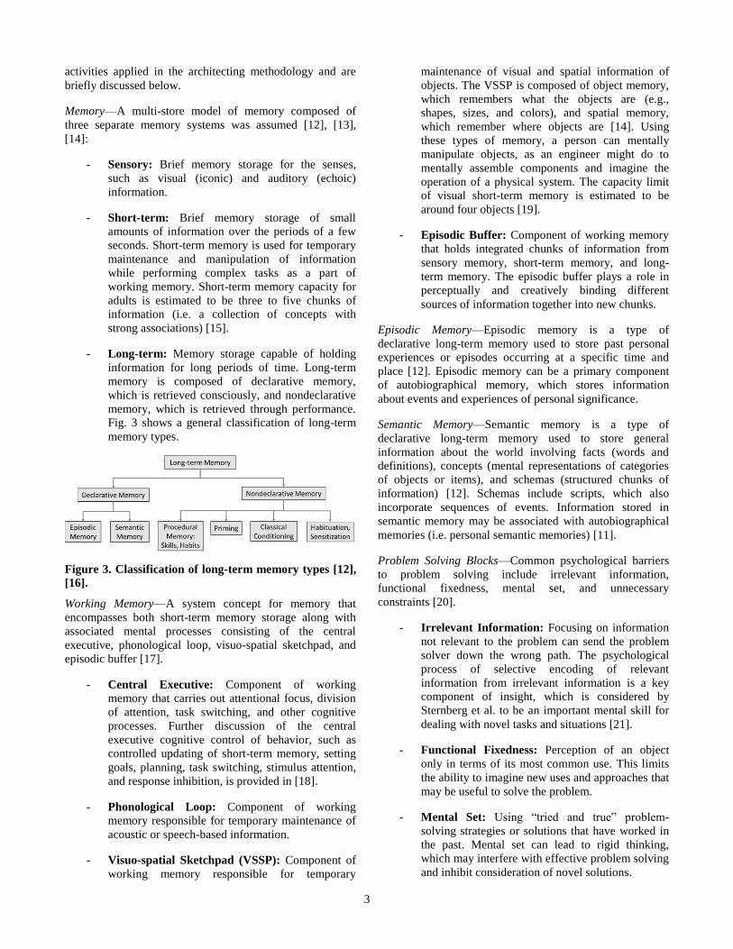
- Long-term: Memory storage capable of holding
information for long periods of time. Long-term
memory is composed of declarative memory,
which is retrieved consciously, and nondeclarative
memory, which is retrieved through performance.
Fig. 3 shows a general classification of long-term
memory types.
Figure 3. Classification of long-term memory types [12],
[16].
Working Memory—A system concept for memory that
encompasses both short-term memory storage along with
associated mental processes consisting of the central
executive, phonological loop, visuo-spatial sketchpad, and
episodic buffer [17].
- Central Executive: Component of working
memory that carries out attentional focus, division
of attention, task switching, and other cognitive
processes. Further discussion of the central
executive cognitive control of behavior, such as
controlled updating of short-term memory, setting
goals, planning, task switching, stimulus attention,
and response inhibition, is provided in [18].
- Phonological Loop: Component of working
memory responsible for temporary maintenance of
acoustic or speech-based information.
- Visuo-spatial Sketchpad (VSSP): Component of
working memory responsible for temporary
maintenance of visual and spatial information of
objects. The VSSP is composed of object memory,
which remembers what the objects are (e.g.,
shapes, sizes, and colors), and spatial memory,
which remember where objects are [14]. Using
these types of memory, a person can mentally
manipulate objects, as an engineer might do to
mentally assemble components and imagine the
operation of a physical system. The capacity limit
of visual short-term memory is estimated to be
around four objects [19].
- Episodic Buffer: Component of working memory
that holds integrated chunks of information from
sensory memory, short-term memory, and long-
term memory. The episodic buffer plays a role in
perceptually and creatively binding different
sources of information together into new chunks.
Episodic Memory—Episodic memory is a type of
declarative long-term memory used to store past personal
experiences or episodes occurring at a specific time and
place [12]. Episodic memory can be a primary component
of autobiographical memory, which stores information
about events and experiences of personal significance.
Semantic Memory—Semantic memory is a type of
declarative long-term memory used to store general
information about the world involving facts (words and
definitions), concepts (mental representations of categories
of objects or items), and schemas (structured chunks of
information) [12]. Schemas include scripts, which also
incorporate sequences of events. Information stored in
semantic memory may be associated with autobiographical
memories (i.e. personal semantic memories) [11].
Problem Solving Blocks—Common psychological barriers
to problem solving include irrelevant information,
functional fixedness, mental set, and unnecessary
constraints [20].
- Irrelevant Information: Focusing on information
not relevant to the problem can send the problem
solver down the wrong path. The psychological
process of selective encoding of relevant
information from irrelevant information is a key
component of insight, which is considered by
Sternberg et al. to be an important mental skill for
dealing with novel tasks and situations [21].
- Functional Fixedness: Perception of an object
only in terms of its most common use. This limits
the ability to imagine new uses and approaches that
may be useful to solve the problem.
- Mental Set: Using “tried and true” problem-
solving strategies or solutions that have worked in
the past. Mental set can lead to rigid thinking,
which may interfere with effective problem solving
and inhibit consideration of novel solutions.
4
- Unnecessary Constraints: Assuming constraints
that do not exist. Overconstraining the problem can
make the problem more difficult or impossible to
effectively solve.
Education
Principles of Learning and Bloom’s Taxonomy are two
concepts from the field of education that are applied in the
architecting methodology.
Principles of Learning—Three research-based principles
from the science of learning are discussed in [22] and
summarized below:
- Dual Channels Principle: People possess two
separate channels, a verbal and a visual, to process
information. Representing incoming information
both visually and verbally can improve
comprehension and retention.
- Limited Capacity Principle: People can only
process a small amount of information in each
channel at any one time due to storage limitations
in their working memory. Encoding information
into chunks can provides a means for people to
have access to more information in their working
memory. Additionally, reducing extraneous
information can make more working memory
available for processing the more relevant,
essential information.
- Active Processing: Meaningful learning occurs
when people actively engage in cognitive
processing of the information through proper
selection (i.e. focusing attention onto), organization
(i.e. mentally organizing and representing the
information verbally and pictorially in working
memory), and integration with prior knowledge
(i.e. knowledge in long-term memory).
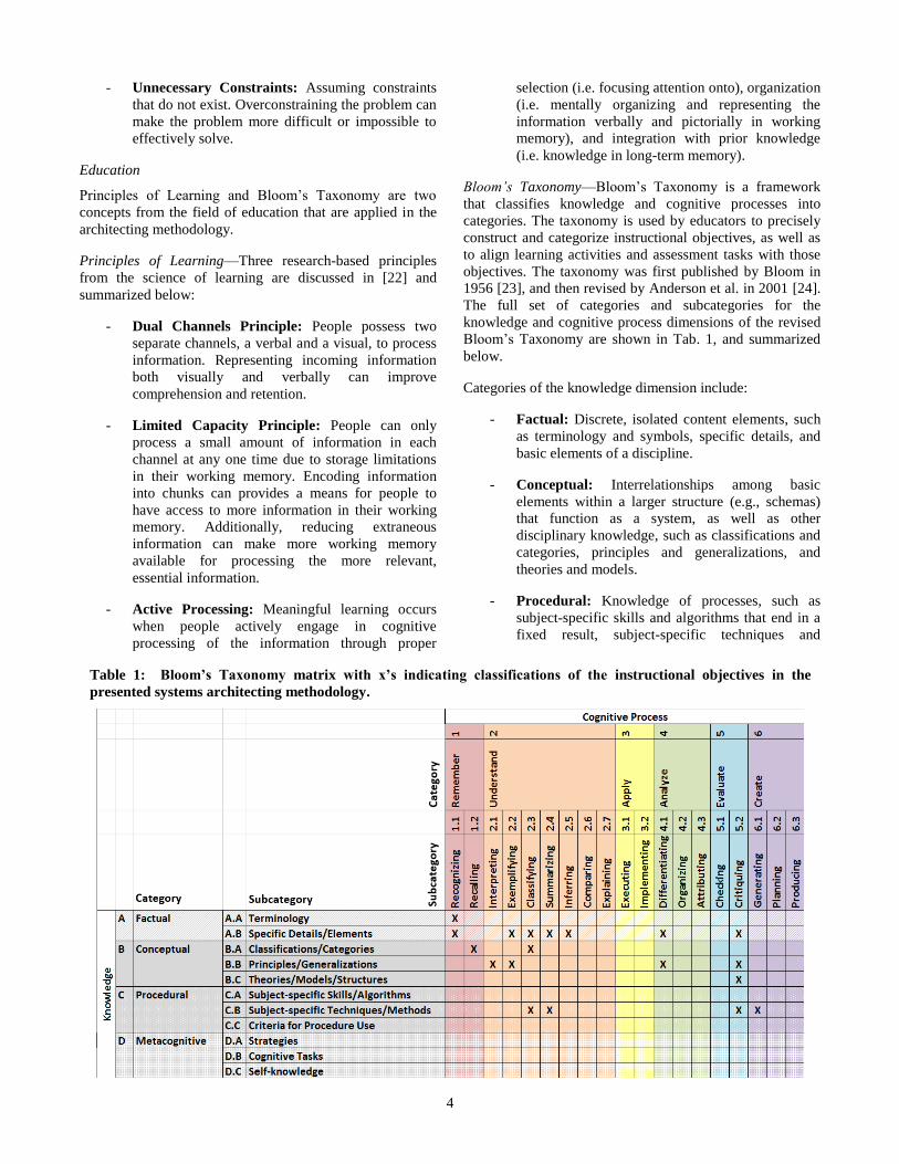
Bloom’s Taxonomy—Bloom’s Taxonomy is a framework
that classifies knowledge and cognitive processes into
categories. The taxonomy is used by educators to precisely
construct and categorize instructional objectives, as well as
to align learning activities and assessment tasks with those
objectives. The taxonomy was first published by Bloom in
1956 [23], and then revised by Anderson et al. in 2001 [24].
The full set of categories and subcategories for the
knowledge and cognitive process dimensions of the revised
Bloom’s Taxonomy are shown in Tab. 1, and summarized
below.
Categories of the knowledge dimension include:
- Factual: Discrete, isolated content elements, such
as terminology and symbols, specific details, and
basic elements of a discipline.
- Conceptual: Interrelationships among basic
elements within a larger structure (e.g., schemas)
that function as a system, as well as other
disciplinary knowledge, such as classifications and
categories, principles and generalizations, and
theories and models.
- Procedural: Knowledge of processes, such as
subject-specific skills and algorithms that end in a
fixed result, subject-specific techniques and
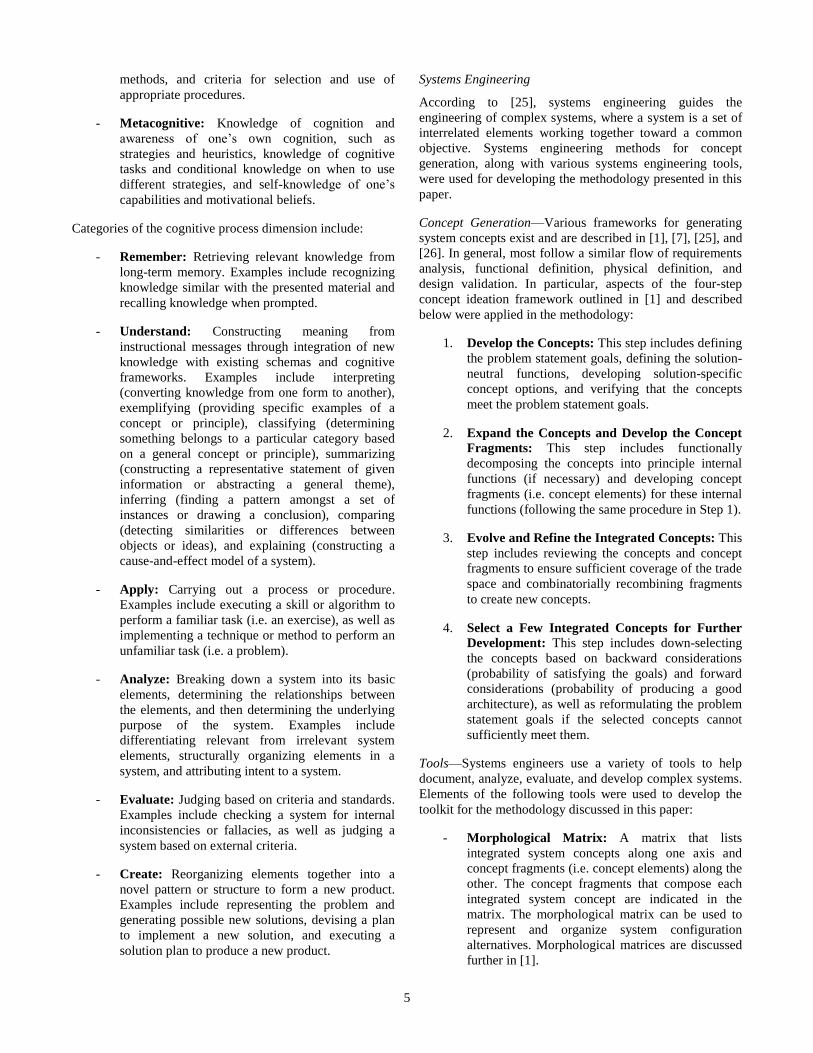
Table 1: Bloom’s Taxonomy matrix with x’s indicating classifications of the instructional objectives in the
presented systems architecting methodology.
5
methods, and criteria for selection and use of
appropriate procedures.
- Metacognitive: Knowledge of cognition and
awareness of one’s own cognition, such as
strategies and heuristics, knowledge of cognitive
tasks and conditional knowledge on when to use
different strategies, and self-knowledge of one’s
capabilities and motivational beliefs.
Categories of the cognitive process dimension include:
- Remember: Retrieving relevant knowledge from
long-term memory. Examples include recognizing
knowledge similar with the presented material and
recalling knowledge when prompted.
- Understand: Constructing meaning from
instructional messages through integration of new
knowledge with existing schemas and cognitive
frameworks. Examples include interpreting
(converting knowledge from one form to another),
exemplifying (providing specific examples of a
concept or principle), classifying (determining
something belongs to a particular category based
on a general concept or principle), summarizing
(constructing a representative statement of given
information or abstracting a general theme),
inferring (finding a pattern amongst a set of
instances or drawing a conclusion), comparing
(detecting similarities or differences between
objects or ideas), and explaining (constructing a
cause-and-effect model of a system).
- Apply: Carrying out a process or procedure.
Examples include executing a skill or algorithm to
perform a familiar task (i.e. an exercise), as well as
implementing a technique or method to perform an
unfamiliar task (i.e. a problem).
- Analyze: Breaking down a system into its basic
elements, determining the relationships between
the elements, and then determining the underlying
purpose of the system. Examples include
differentiating relevant from irrelevant system
elements, structurally organizing elements in a
system, and attributing intent to a system.
- Evaluate: Judging based on criteria and standards.
Examples include checking a system for internal
inconsistencies or fallacies, as well as judging a
system based on external criteria.
- Create: Reorganizing elements together into a
novel pattern or structure to form a new product.
Examples include representing the problem and
generating possible new solutions, devising a plan
to implement a new solution, and executing a
solution plan to produce a new product.
Systems Engineering
According to [25], systems engineering guides the
engineering of complex systems, where a system is a set of
interrelated elements working together toward a common
objective. Systems engineering methods for concept
generation, along with various systems engineering tools,
were used for developing the methodology presented in this
paper.
Concept Generation—Various frameworks for generating
system concepts exist and are described in [1], [7], [25], and
[26]. In general, most follow a similar flow of requirements
analysis, functional definition, physical definition, and
design validation. In particular, aspects of the four-step
concept ideation framework outlined in [1] and described
below were applied in the methodology:
1. Develop the Concepts: This step includes defining
the problem statement goals, defining the solution-
neutral functions, developing solution-specific
concept options, and verifying that the concepts
meet the problem statement goals.
2. Expand the Concepts and Develop the Concept
Fragments: This step includes functionally
decomposing the concepts into principle internal
functions (if necessary) and developing concept
fragments (i.e. concept elements) for these internal
functions (following the same procedure in Step 1).
3. Evolve and Refine the Integrated Concepts: This
step includes reviewing the concepts and concept
fragments to ensure sufficient coverage of the trade
space and combinatorially recombining fragments
to create new concepts.
4. Select a Few Integrated Concepts for Further
Development: This step includes down-selecting
the concepts based on backward considerations
(probability of satisfying the goals) and forward
considerations (probability of producing a good
architecture), as well as reformulating the problem
statement goals if the selected concepts cannot
sufficiently meet them.
Tools—Systems engineers use a variety of tools to help
document, analyze, evaluate, and develop complex systems.
Elements of the following tools were used to develop the
toolkit for the methodology discussed in this paper:
- Morphological Matrix: A matrix that lists
integrated system concepts along one axis and
concept fragments (i.e. concept elements) along the
other. The concept fragments that compose each
integrated system concept are indicated in the
matrix. The morphological matrix can be used to
represent and organize system configuration
alternatives. Morphological matrices are discussed
further in [1].
6
- Design Structure Matrix: A matrix that lists
system components on both axes. Connections
from components flowing from one axis to each
component on the other axis are indicated in the
matrix. The design structure matrix can be used to
show spatial, topological, and connectivity
relationships between system components. Design
structure matrices are discussed further in [1].
- House of Quality Diagram: A diagram developed
through the Quality Function Deployment (QFD)
method that captures the customers, customers’
requirements, system concept alternatives,
relationships between the system concepts and
requirements, target engineering specifications, and
interdependencies of engineering specifications.
The method can be effective at collecting and
refining functional requirements from the
customer. House of Quality Diagrams and the QFD
method are discussed further in [7] and [27].
- Decision Matrix: A matrix developed through the
Pugh method that captures and scores system
concept alternatives (listed along one axis) over a
set of criteria (listed along the other axis with
weights). Scores are provided for each alternative
over each criteria within the matrix. A total
weighted score is calculated and reported for each
alternative. Decision matrices, the Pugh method,
and alternate decision matrices and methods are
discussed further in [7], [26], and [28].
3. SYSTEMS ARCHITECTING APPROACH
The systems architecting methodology proposed in this
paper was constructed around a 6 Ps Creativity Framework,
which was built upon the 4 Ps framework (Product, Person,
Process, Press) proposed by Rhodes in [10]. Additionally,
the methodology acknowledges that creativity stems from
domain expertise, as well as higher levels of cognitive
processing. The 6 Ps Creativity Framework, along with the
use of Bloom’s Taxonomy to generate expert knowledge
and implement higher levels of cognitive processing, are
described in this section.
6 Ps Creativity Framework
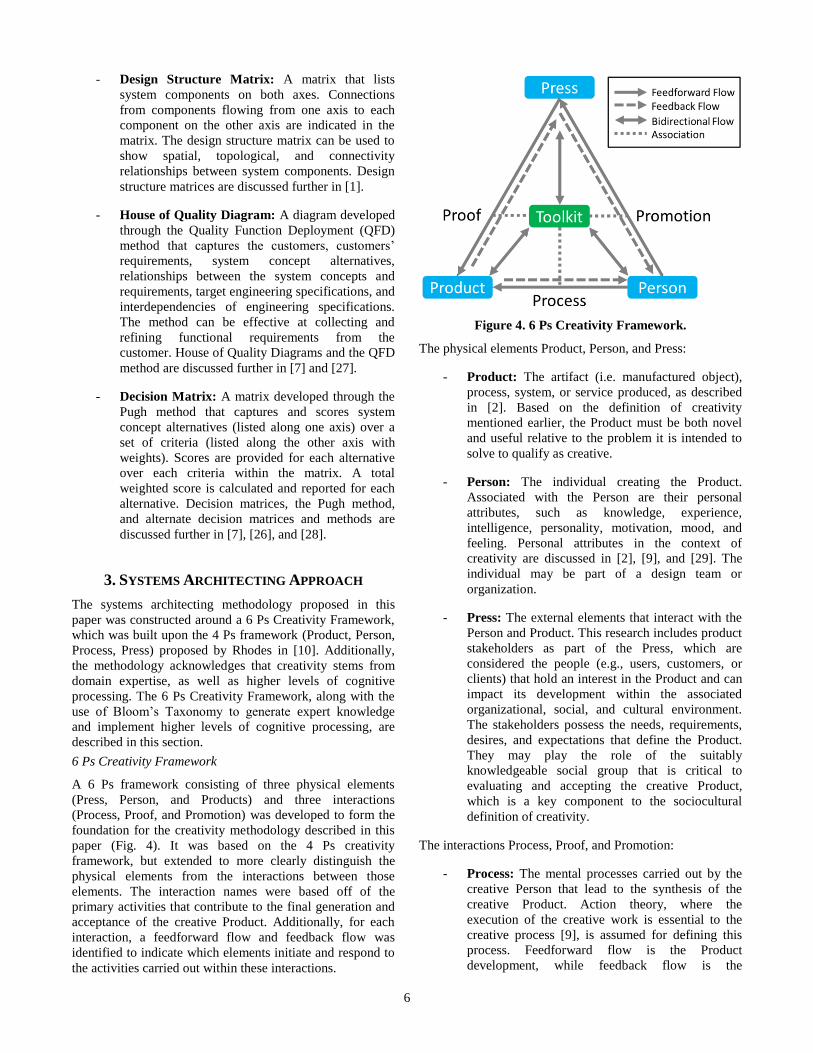
A 6 Ps framework consisting of three physical elements
(Press, Person, and Products) and three interactions
(Process, Proof, and Promotion) was developed to form the
foundation for the creativity methodology described in this
paper (Fig. 4). It was based on the 4 Ps creativity
framework, but extended to more clearly distinguish the
physical elements from the interactions between those
elements. The interaction names were based off of the
primary activities that contribute to the final generation and
acceptance of the creative Product. Additionally, for each
interaction, a feedforward flow and feedback flow was
identified to indicate which elements initiate and respond to
the activities carried out within these interactions.
Figure 4. 6 Ps Creativity Framework.
The physical elements Product, Person, and Press:
- Product: The artifact (i.e. manufactured object),
process, system, or service produced, as described
in [2]. Based on the definition of creativity
mentioned earlier, the Product must be both novel
and useful relative to the problem it is intended to
solve to qualify as creative.
- Person: The individual creating the Product.
Associated with the Person are their personal
attributes, such as knowledge, experience,
intelligence, personality, motivation, mood, and
feeling. Personal attributes in the context of
creativity are discussed in [2], [9], and [29]. The
individual may be part of a design team or
organization.
- Press: The external elements that interact with the
Person and Product. This research includes product
stakeholders as part of the Press, which are
considered the people (e.g., users, customers, or
clients) that hold an interest in the Product and can
impact its development within the associated
organizational, social, and cultural environment.
The stakeholders possess the needs, requirements,
desires, and expectations that define the Product.
They may play the role of the suitably
knowledgeable social group that is critical to
evaluating and accepting the creative Product,
which is a key component to the sociocultural
definition of creativity.
The interactions Process, Proof, and Promotion:
- Process: The mental processes carried out by the
creative Person that lead to the synthesis of the
creative Product. Action theory, where the
execution of the creative work is essential to the
creative process [9], is assumed for defining this
process. Feedforward flow is the Product
development, while feedback flow is the
7
verification of the Product. This feedback helps the
Person assess the state of the Product and its
performance relative to the design criteria.
- Proof: The use of the Product by the Press for the
purpose of validating its operation. Feedforward
flow is the stakeholder’s use or perception of the
Product (either the Product itself, or a
physical/virtual prototype of the Product) in order
to test the Product and assess how it meets their
needs, requirements, desires, and expectations.
Feedback flow is the validation of the Product from
the testing or assessment. This feedback informs
the stakeholders of the Product’s capabilities and
limitations, which can help recalibrate stakeholder
expectations of the Product, as well as lead to the
creation or discovery of new requirements and use
cases.
- Promotion: The activity carried out by the Person
to encourage adoption of the Product by the Press.
Feedforward flow is the promotional pitch of the
Product to the Press to inform them of the Product
and its capabilities, persuade them to choose and
adopt the Product (potentially amongst competing
alternatives), and remind them of the Product to
maintain awareness of it. This activity draws from
the marketing definition of Promotion, which is to
inform, persuade, and influence the consumer’s
purchase decision [30]. Feedback flow is a design
review, providing stakeholder input to the Person
about the Product and its development. For
Promotion to be most effective, it should be
tailored to both the specific individual promoting
the Product and the specific stakeholder (e.g., the
particular market segment) it is directed towards.
The Toolkit contains the tools and materials used by the
Person, Press, and Product to carry out the Proof,
Promotion, and Process activities. These tools may capture
information, assist with learning, and facilitate information
transfer. Therefore, the bidirectional flows shown in Fig. 4
between the Toolkit and the three surrounding elements
(Person, Product, and Press) may be considered learning.
Within the context of systems architecting, this research
focuses on the creative synthesis (Process) of a novel system
architecture (Product), carried out by a system architect
(Person), for specific stakeholders (Press), though the use of
a set of learning tools (Toolkit). Product Promotion and
Proof are also acknowledged as key contributors to
successfully producing the creative Product, but are not the
primary focus of the methodology discussed in this paper.
The methodology is structured around a Toolkit composed
of tools derived from systems engineering tools, carried out
through a Process based on creativity research, with an
emphasis on knowledge generation using principles of
learning from educational psychology, while acknowledging
cognitive constraints and problem solving blocks identified
from cognitive psychology research.
Knowledge Generation using Bloom’s Taxonomy
A constructivist learning approach to promote meaningful
learning and generate deeper knowledge that can be
transferred to synthesize new system architectures was
taken. The approach generates deeper knowledge and elicits
more complex thinking through methodically implementing
learning activities that incrementally increase in both
complexity of knowledge and cognitive processing using
the Bloom’s Taxonomy framework (Tab. 2). This strategy is
based upon research showing that deeper processing
strengthens memory traces in long-term memory [31].
Specialized tools were developed, along with associated
procedures, to implement these learning activities during the
architecting process. The overall sequence in which these
learning tools are implemented was structured around the
eight creativity stages proposed by Sawyer in [9]. Within
each tool, the subcategories of Bloom’s Taxonomy were
used to classify the instructional objectives and the
generated knowledge to a level of specificity that can help
promote effective communication, understanding,
implementation, analysis, evaluation, and improvement of
the tools.
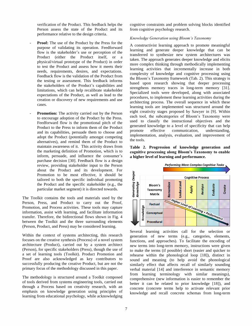
Table 2. Progression of knowledge generation and
cognitive processing along Bloom’s Taxonomy to enable
a higher level of learning and performance.
Several learning activities call for the selection or
generation of new terms (e.g., categories, elements,
functions, and approaches). To facilitate the encoding of
new terms into long-term memory, instructions were given
to make the terms (if possible) short (easier and quicker to
rehearse within the phonological loop [18]), distinct in
sound and meaning (to help avoid the phonological
similarly effect that affects recall of similarly sounding
verbal material [14] and interference in semantic memory
from learning terminology with similar meanings),
comprehensive (new information is easier to remember the
better it can be related to prior knowledge [18]), and
concrete (concrete terms help to activate relevant prior
knowledge and recall concrete schemas from long-term
8
memory that provide useful analogies to support meaningful
learning through the process of elaboration [32]).
Several learning activities call for grouping items into
categories. For these activities, instructions were given to
group items into no more than five. Doing so enables
cognitive processing of items within the category (e.g.,
comparative analysis) by keeping the number of items in
short-term memory within the memory capacity of five
chunks, as well as facilitates the development of new
chunks composed of the items within the category. Creating
chunks can aid in long-term memory encoding and retrieval,
reduce cognitive load when processing the information, and
provide a means to access more information in working
memory when the chunks are recalled.
4. SYSTEMS ARCHITECTING TOOLS
Tools developed for the methodology are described in this
section. For each tool, an educational objective, brief
description, overall layout, and procedure for use are
provided. Blocks of information within the layout are
numbered based on the recommended order to complete
them. Blocks that represent a learning activity are color-
coded in the layout and classified with Bloom’s Taxonomy
based on their learning objectives, which are listed in a
separate table. Blocks that are colored gray and not listed in
the table are merely for reference and do not have a specific
instructional objective associated with them (though this
information may be used for other learning activities). For
each instructional objective, the specific cognitive process
and knowledge subcategory are provided in parenthesis for
reference. For example, an instructional objective that
consists of classifying (Cognitive Process subcategory 2.3 in
Tab. 1) techniques (Knowledge subcategory C.B in Tab. 1)
is notated as “(2.3-C.B)”. Additionally, for each
instructional objective, the learning outcome in terms of
knowledge generated is specified, along with its knowledge
subcategory in parenthesis.
Function Tree
Educational Objective—Ability to provide examples of
specific functional techniques to achieve the overall system
operational objective.
Tool Description—This tool interprets the system
operational objective in terms of a basic general function. A
tree consisting of possible functional techniques branch
from the general function. This tool helps develop a deeper
understanding of the system operational objective and
communicates possible techniques to perform the function.
This tool generalizes the operational objective to help
disassociate preconceived solutions that may limit creative
thinking and allows for redefinition and reframing of the
problem in different ways to help with the search,
identification, generation, and classification of additional
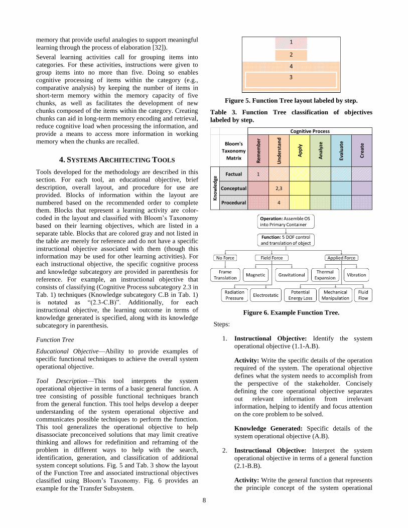
system concept solutions. Fig. 5 and Tab. 3 show the layout
of the Function Tree and associated instructional objectives
classified using Bloom’s Taxonomy. Fig. 6 provides an
example for the Transfer Subsystem.
Figure 5. Function Tree layout labeled by step.
Table 3. Function Tree classification of objectives
labeled by step.
Bloom's
Taxonomy
Matrix
Cognitive Process
Rem
emb
er
Un
der
stan
d
Ap
ply
An
alyz
e
Eval
uat
e
Cre
ate
Kn
ow
led
ge
Factual 1
Procedural 4
Conceptual 2,3
Figure 6. Example Function Tree.
Steps:
1. Instructional Objective: Identify the system
operational objective (1.1-A.B).
Activity: Write the specific details of the operation
required of the system. The operational objective
defines what the system needs to accomplish from
the perspective of the stakeholder. Concisely
defining the core operational objective separates
out relevant information from irrelevant
information, helping to identify and focus attention
on the core problem to be solved.
Knowledge Generated: Specific details of the
system operational objective (A.B).
2. Instructional Objective: Interpret the system
operational objective in terms of a general function
(2.1-B.B).
Activity: Write the general function that represents
the principle concept of the system operational
9
objective in its most basic, first principles,
foundational constructs (e.g., in terms of basic
physics). Generalizing the operational objective
into an implementation independent function helps
overcome mental set by abstracting out previous
physical design solution assumptions that may be
associated with the operational objective.
Knowledge Generated: General system function
(B.B).
3. Instructional Objective: Provide examples of
specific techniques that accomplish the general
function (2.2-B.B).
Activity: Write examples of specific functional
techniques that carry out the system function.
Choose short, distinct, and comprehensive names
for the techniques. The techniques should be
implementation-independent.
Knowledge Generated: Specific system
functional techniques (C.B).
4. Instructional Objective: Classify the functional
techniques (2.3-C.B).
Activity: Arrange the specific system functional
techniques into a categorical hierarchy tree based
on common concepts and principles. Group into
categories of no more than five techniques. Choose
short, distinct, and comprehensive names for
categories.
Knowledge Generated: Functional technique
categories (B.A).
Evaluation Criteria Table
Educational Objective—Ability to explain a set of
evaluation criteria and their relative importance with respect
to the system.
Tool Description—This tool defines a set of criteria for
evaluating the system concepts. The table contains the
criteria, its definition, examples of systems that do well
(satisfactory) and poorly (unsatisfactory) with respect to the
criteria, an assigned weight to communicate importance
with respect to the system, and rationale for the weight. The
satisfactory and unsatisfactory system examples help
calibrate the minimum and maximum scores when applying
the Evaluation Criteria in the Systems Evaluation Matrices,
as well as help make abstract criteria more concrete
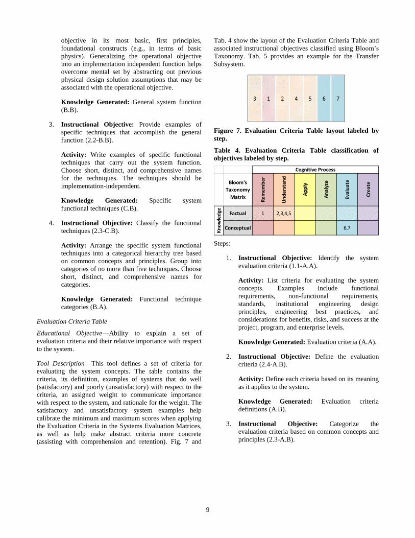
(assisting with comprehension and retention). Fig. 7 and
Tab. 4 show the layout of the Evaluation Criteria Table and
associated instructional objectives classified using Bloom’s
Taxonomy. Tab. 5 provides an example for the Transfer
Subsystem.
Figure 7. Evaluation Criteria Table layout labeled by
step.
Table 4. Evaluation Criteria Table classification of
objectives labeled by step.
Bloom's
Taxonomy
Matrix
Conceptual 6,7
Cognitive Process
Rem
emb
er
Un
der
stan
d
Ap
ply
An
alyz
e
Eval
uat
e
Cre
ate
Kn
ow
led
ge Factual 1 2,3,4,5
Steps:
1. Instructional Objective: Identify the system
evaluation criteria (1.1-A.A).
Activity: List criteria for evaluating the system
concepts. Examples include functional
requirements, non-functional requirements,
standards, institutional engineering design
principles, engineering best practices, and
considerations for benefits, risks, and success at the
project, program, and enterprise levels.
Knowledge Generated: Evaluation criteria (A.A).
2. Instructional Objective: Define the evaluation
criteria (2.4-A.B).
Activity: Define each criteria based on its meaning
as it applies to the system.
Knowledge Generated: Evaluation criteria
definitions (A.B).
3. Instructional Objective: Categorize the
evaluation criteria based on common concepts and
principles (2.3-A.B).
10
Activity: Rearrange the criteria into categories
based on common concepts and principles. Group
into categories of no more than five criteria. Use
several levels of categories if needed, creating new
columns to the left of the criteria for each category
level. Choose short, distinct, and comprehensive
names for categories.
Knowledge Generated: Evaluation criteria
categories (B.A).
4. Instructional Objective: Provide an example of a
satisfactory system for each evaluation criteria
(2.2-A.B).
Activity: Write an example of a system that
satisfies each evaluation criteria, along with a short
explanation of why. Providing more concrete
examples better supports understanding of the
criteria.
Knowledge Generated: System examples that
satisfy the criteria (B.A).
5. Instructional Objective: Provide an example of
an unsatisfactory system for each evaluation
criteria (2.2-A.B).
Activity: Write an example of a system that does
not satisfy each evaluation criteria, along with a
short explanation of why. Providing more concrete
examples better supports understanding of the
criteria.
Knowledge Generated: System examples that do
not satisfy the criteria (B.A).
6. Instructional Objective: Weight each criteria
based on importance to the system relative to other
criteria (5.2-B.B).
Activity: Write a numerical weight for each
criteria based on its importance to the system
relative to the other criteria. Examples of methods
for determining weights are described in [25], [26],
and [34]. Individually evaluating the importance of
each criteria helps identify any unnecessary
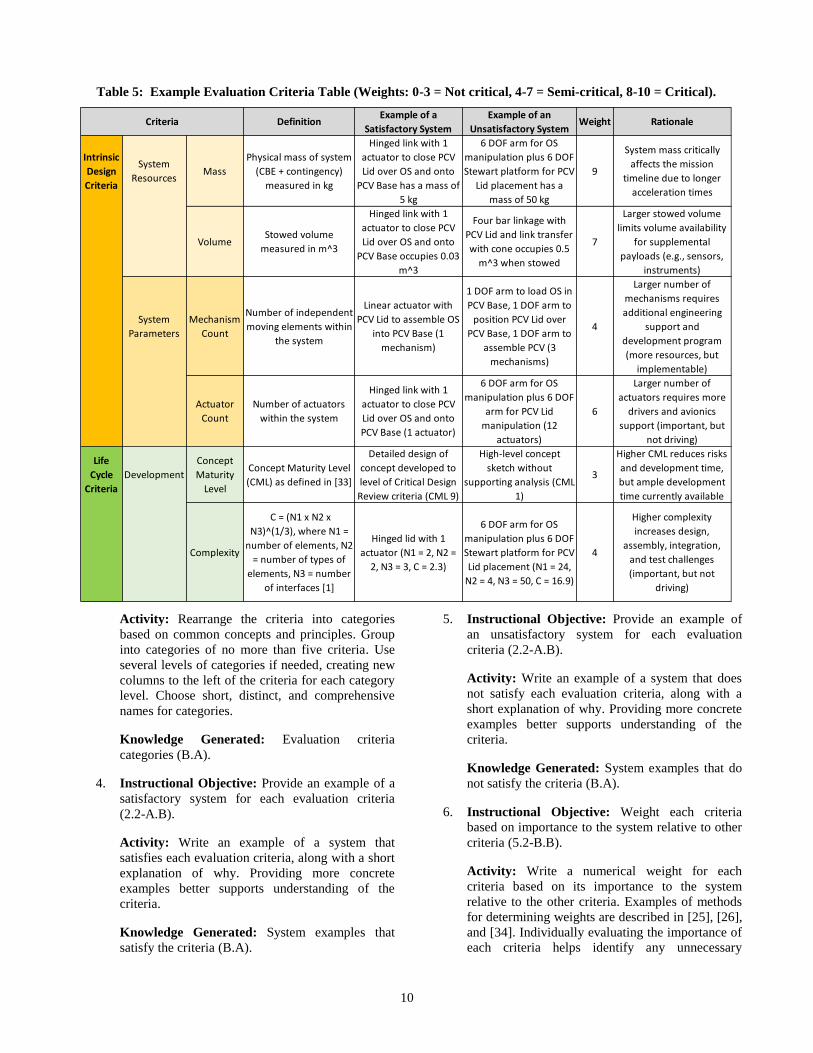
Table 5: Example Evaluation Criteria Table (Weights: 0-3 = Not critical, 4-7 = Semi-critical, 8-10 = Critical).
DefinitionExample of a
Satisfactory System
Example of an
Unsatisfactory SystemWeight Rationale
Intrinsic
Design
Criteria
System
ResourcesMass
Physical mass of system
(CBE + contingency)
measured in kg
Hinged link with 1
actuator to close PCV
Lid over OS and onto
PCV Base has a mass of
5 kg
6 DOF arm for OS
manipulation plus 6 DOF
Stewart platform for PCV
Lid placement has a
mass of 50 kg
9
System mass critically
affects the mission
timeline due to longer
acceleration times
VolumeStowed volume
measured in m^3
Hinged link with 1
actuator to close PCV
Lid over OS and onto
PCV Base occupies 0.03
m^3
Four bar linkage with
PCV Lid and link transfer
with cone occupies 0.5
m^3 when stowed
7
Larger stowed volume
limits volume availability
for supplemental
payloads (e.g., sensors,
instruments)
System
Parameters
Mechanism
Count
Number of independent
moving elements within
the system
Linear actuator with
PCV Lid to assemble OS
into PCV Base (1
mechanism)
1 DOF arm to load OS in
PCV Base, 1 DOF arm to
position PCV Lid over
PCV Base, 1 DOF arm to
assemble PCV (3
mechanisms)
4
Larger number of
mechanisms requires
additional engineering
support and
development program
(more resources, but
implementable)
Actuator
Count
Number of actuators
within the system
Hinged link with 1
actuator to close PCV
Lid over OS and onto
PCV Base (1 actuator)
6 DOF arm for OS
manipulation plus 6 DOF
arm for PCV Lid
manipulation (12
actuators)
6
Larger number of
actuators requires more
drivers and avionics
support (important, but
not driving)
Life
Cycle
Criteria
Development
Concept
Maturity
Level
Concept Maturity Level
(CML) as defined in [33]
Detailed design of
concept developed to
level of Critical Design
Review criteria (CML 9)
High-level concept
sketch without
supporting analysis (CML
1)
3
Higher CML reduces risks
and development time,
but ample development
time currently available
Complexity
C = (N1 x N2 x
N3)^(1/3), where N1 =
number of elements, N2
= number of types of
elements, N3 = number
of interfaces [1]
Hinged lid with 1
actuator (N1 = 2, N2 =
2, N3 = 3, C = 2.3)
6 DOF arm for OS
manipulation plus 6 DOF
Stewart platform for PCV
Lid placement (N1 = 24,
N2 = 4, N3 = 50, C = 16.9)
4
Higher complexity
increases design,
assembly, integration,
and test challenges
(important, but not
driving)
Criteria
11
constraints (through application of lower weights
relative to more important constraints).
Knowledge Generated: Evaluation criteria
weights (B.A).
7. Instructional Objective: Provide the rationale for
each evaluation criteria weight (5.2-B.B).
Activity: Write the rationale for the weight
assignment for each evaluation criteria.
Knowledge Generated: Evaluation criteria weight
rationales (A.B).
Discovered Systems Evaluation Matrix
Educational Objective—Ability to explain existing system
concepts and their functional technique, structure,
composition, and assessment with respect to the evaluation
criteria.
Tool Description—This tool captures knowledge of existing
relevant systems, their function, structure, and elements, as
well as their assessment relative to the set of evaluation
criteria defined in the Evaluation Criteria Table. Blocks 1, 2,
and 3 reproduce the evaluation criteria from the Evaluation
Criteria Table in the same categorical grouping, along with
their weights, so that they can be applied in the Systems
Evaluation Matrix. Blocks labelled 0 are optional, but may
be useful for understanding the system concepts and
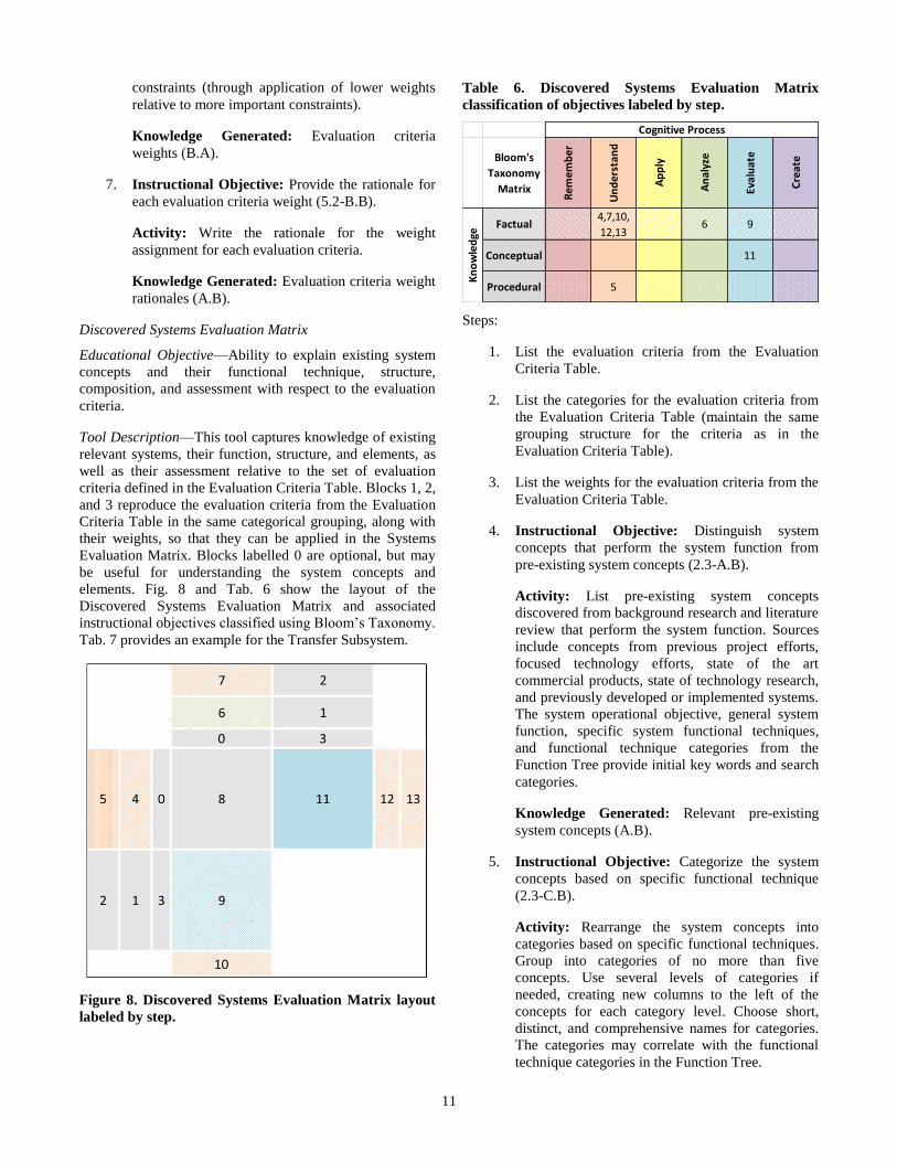
elements. Fig. 8 and Tab. 6 show the layout of the
Discovered Systems Evaluation Matrix and associated
instructional objectives classified using Bloom’s Taxonomy.
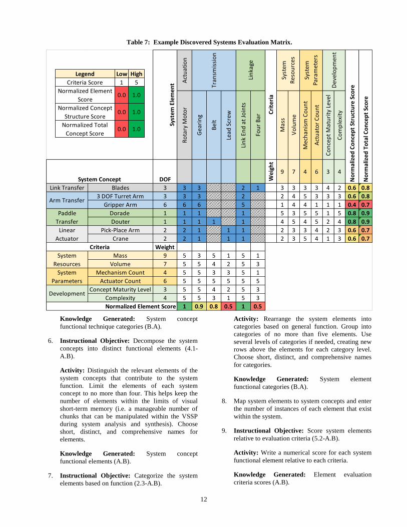
Tab. 7 provides an example for the Transfer Subsystem.
Figure 8. Discovered Systems Evaluation Matrix layout
labeled by step.
Table 6. Discovered Systems Evaluation Matrix
classification of objectives labeled by step.
Bloom's
Taxonomy
Matrix
Procedural 5
Kn
ow
led
ge
Factual
Conceptual
Rem
emb
er
Un
der
stan
d
Ap
ply
An
alyz
e
Eval
uat
e
Cre
ate
6 9
11
4,7,10,
12,13
Cognitive Process
Steps:
1. List the evaluation criteria from the Evaluation
Criteria Table.
2. List the categories for the evaluation criteria from
the Evaluation Criteria Table (maintain the same
grouping structure for the criteria as in the
Evaluation Criteria Table).
3. List the weights for the evaluation criteria from the
Evaluation Criteria Table.
4. Instructional Objective: Distinguish system
concepts that perform the system function from
pre-existing system concepts (2.3-A.B).
Activity: List pre-existing system concepts
discovered from background research and literature
review that perform the system function. Sources
include concepts from previous project efforts,
focused technology efforts, state of the art
commercial products, state of technology research,
and previously developed or implemented systems.
The system operational objective, general system
function, specific system functional techniques,
and functional technique categories from the
Function Tree provide initial key words and search
categories.
Knowledge Generated: Relevant pre-existing
system concepts (A.B).
5. Instructional Objective: Categorize the system
concepts based on specific functional technique
(2.3-C.B).
Activity: Rearrange the system concepts into
categories based on specific functional techniques.
Group into categories of no more than five
concepts. Use several levels of categories if
needed, creating new columns to the left of the
concepts for each category level. Choose short,
distinct, and comprehensive names for categories.
The categories may correlate with the functional
technique categories in the Function Tree.
12
Knowledge Generated: System concept
functional technique categories (B.A).
6. Instructional Objective: Decompose the system
concepts into distinct functional elements (4.1-
A.B).
Activity: Distinguish the relevant elements of the
system concepts that contribute to the system
function. Limit the elements of each system
concept to no more than four. This helps keep the
number of elements within the limits of visual
short-term memory (i.e. a manageable number of
chunks that can be manipulated within the VSSP
during system analysis and synthesis). Choose
short, distinct, and comprehensive names for
elements.
Knowledge Generated: System concept
functional elements (A.B).
7. Instructional Objective: Categorize the system
elements based on function (2.3-A.B).
Activity: Rearrange the system elements into
categories based on general function. Group into
categories of no more than five elements. Use
several levels of categories if needed, creating new
rows above the elements for each category level.
Choose short, distinct, and comprehensive names
for categories.
Knowledge Generated: System element
functional categories (B.A).
8. Map system elements to system concepts and enter
the number of instances of each element that exist
within the system.
9. Instructional Objective: Score system elements
relative to evaluation criteria (5.2-A.B).
Activity: Write a numerical score for each system
functional element relative to each criteria.
Knowledge Generated: Element evaluation
criteria scores (A.B).
Table 7: Example Discovered Systems Evaluation Matrix.
Act
uat
ion
Ro
tary
Mo
tor
Gea
rin
g
Bel
t
Lead
Scr
ew
Lin
k En
d a
t Jo
ints
Fou
r B
ar
Mas
s
Vo
lum
e
Mec
han
ism
Co
un
t
Act
uat
or
Co
un
t
Co
nce
pt
Mat
uri
ty L
evel
Co
mp
lexi
ty
DOF Wei
ght
9 7 4 6 3 4
Link Transfer Blades 3 3 3 2 1 3 3 3 3 4 2 0.6 0.8
3 DOF Turret Arm 3 3 3 2 2 4 5 3 3 3 0.6 0.8
Gripper Arm 6 6 6 5 1 4 4 1 1 1 0.4 0.7
Dorade 1 1 1 1 5 3 5 5 1 5 0.8 0.9
Douter 1 1 1 1 1 4 5 4 5 2 4 0.8 0.9
Pick-Place Arm 2 2 1 1 1 2 3 3 4 2 3 0.6 0.7
Crane 2 2 1 1 1 2 3 5 4 1 3 0.6 0.7
Weight
Mass 9 5 3 5 1 5 1
Volume 7 5 5 4 2 5 3
Mechanism Count 4 5 5 3 3 5 1
Actuator Count 6 5 5 5 5 5 5
Concept Maturity Level 3 5 5 4 2 5 3
Complexity 4 5 5 3 1 5 3
1 0.9 0.8 0.5 1 0.5
System
Parameters
Development
No
rmal
ized
Co
nce
pt
Stru
ctu
re S
core
No
rmal
ized
To
tal C
on
cep
t Sc
ore
Normalized Element Score
Arm Transfer
Cri
teri
a
Criteria
Syst
em E
lem
ent
System Concept
Tran
smis
sio
n
Lin
kage
Syst
em
Res
ou
rces
Syst
em
Para
met
ers
Dev
elo
pm
ent
Paddle
Transfer
Linear
Actuator
System
Resources
Legend Low High
Criteria Score 1 5
Normalized Element
Score0.0 1.0
Normalized Concept
Structure Score0.0 1.0
Normalized Total
Concept Score0.0 1.0
13
10. Instructional Objective: Calculate a total
evaluation score for system elements (2.4-A.B).
Activity: Write a total numerical score for each
system element that is a function of each element’s
individual criteria score and the criteria’s weight.
Examples of methods for calculating total scores
are described in [25], [26], and [34].
Knowledge Generated: Total element evaluation
scores (A.B).
11. Instructional Objective: Score system concept
structures relative to evaluation criteria (5.2-B.C).
Activity: Write a numerical score for each
functional system concept relative to each criteria.
The objective is to evaluate the system concepts
based on their system concept structures, the
functional technique that arises from the structures,
and other emergent system properties that arise
from its particular composition of functional
elements, as opposed to the internal attributes of
the functional elements themselves (the functional
elements were evaluated separately in Step 9 and
will be combined with the system concept structure
evaluation scores in Step 13).
Knowledge Generated: System concept structure
evaluation criteria scores (A.B).
12. Instructional Objective: Calculate a total
evaluation score for system concept structures (2.4-
A.B).
Activity: Write a total numerical score for each
system concept structure that is a function of each
concept structure’s individual criteria score and the
criteria’s weight. Examples of methods for
calculating total scores are described in [25], [26],
and [34].
Knowledge Generated: Total system concept
structure evaluation scores (A.B).
13. Instructional Objective: Calculate a total
evaluation score for system concepts (2.4-A.B).
Activity: Write a total numerical score for each
system concept that is a function of both the
concept’s structure and its elements’ scores.
Determining the mathematical method to calculate
the total score may require critiquing the level of
importance (or weight) each element plays in the
final system concept relative to one another, as
well as to the system concept structure.
Knowledge Generated: Total system concept
evaluation scores (A.B).
0. Provide any additional information related to the
system concepts or elements that may help with
their comprehension. These blocks are optional.
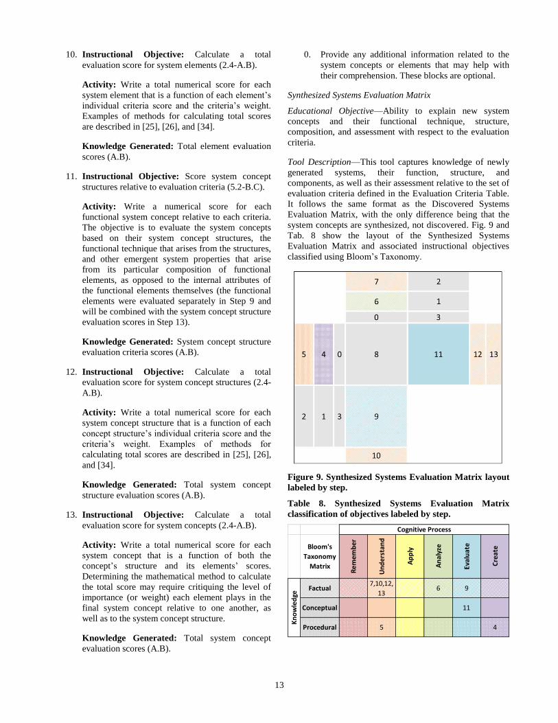
Synthesized Systems Evaluation Matrix
Educational Objective—Ability to explain new system
concepts and their functional technique, structure,
composition, and assessment with respect to the evaluation
criteria.
Tool Description—This tool captures knowledge of newly
generated systems, their function, structure, and
components, as well as their assessment relative to the set of
evaluation criteria defined in the Evaluation Criteria Table.
It follows the same format as the Discovered Systems
Evaluation Matrix, with the only difference being that the
system concepts are synthesized, not discovered. Fig. 9 and
Tab. 8 show the layout of the Synthesized Systems
Evaluation Matrix and associated instructional objectives
classified using Bloom’s Taxonomy.
Figure 9. Synthesized Systems Evaluation Matrix layout
labeled by step.
Table 8. Synthesized Systems Evaluation Matrix
classification of objectives labeled by step.
Bloom's
Taxonomy
Matrix
4
Kn
ow
led
ge
Procedural 5
11
7,10,12,
136
Cognitive Process
Rem
emb
er
Un
der
stan
d
Ap
ply
An
alyz
e
Eval
uat
e
Cre
ate
Conceptual
Factual 9
14
Steps:
1-3. Same as Discovered Systems Evaluation Matrix.
4. Instructional Objective: Generate new system
concepts (6.1-C.B).
Activity: Generate new system concepts using
knowledge from pre-existing system concept
techniques through recombination of existing
elements using existing system concept structures
(evolutionary), combining elements into new
structures (revolutionary), or performing the
aforementioned with newly identified or generated
elements. Choose short, distinct, and
comprehensive names for the new system concepts.
Knowledge Generated: New system concepts
(C.B).
5-13. Same as Discovered Systems Evaluation Matrix.
0. Same as Discovered Systems Evaluation Matrix.
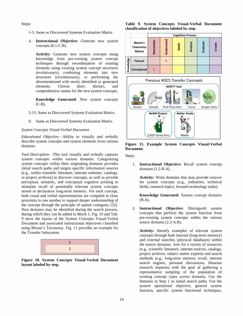
System Concepts Visual-Verbal Document
Educational Objective—Ability to visually and verbally
describe system concepts and system elements from various
domains.
Tool Description—This tool visually and verbally captures
system concepts within various domains. Categorizing
system concepts within their originating domains provides
initial search paths and targets specific information sources
(e.g., within scientific literature, internet websites, catalogs,
or project archives) to discover concepts, as well as provide
perceptual, semantic, and conceptual cognitive priming to
stimulate recall of potentially relevant system concepts
stored in declarative long-term memory. For each concept,
both visual and verbal representations are compiled in close
proximity to one another to support deeper understanding of
the concept through the principle of spatial contiguity [32].
New domains may be identified during the search process,
during which they can be added to Block 1. Fig. 10 and Tab.
9 show the layout of the System Concepts Visual-Verbal
Document and associated instructional objectives classified
using Bloom’s Taxonomy. Fig. 11 provides an example for
the Transfer Subsystem.
Figure 10. System Concepts Visual-Verbal Document
layout labeled by step.
Table 9. System Concepts Visual-Verbal Document
classification of objectives labeled by step.
Bloom's
Taxonomy
Matrix
Cognitive Process
Rem
emb
er
Un
der
stan
d
Ap
ply
An
alyz
e
Eval
uat
e
Cre
ate
Kn
ow
led
ge Factual 2
Conceptual 1
Figure 11. Example System Concepts Visual-Verbal
Document.
Steps:
1. Instructional Objective: Recall system concept
domains (1.2-B.A).
Activity: Write domains that may provide sources
for system concepts (e.g., industries, technical
fields, research topics, focused technology tasks).
Knowledge Generated: System concept domains
(B.A).
2. Instructional Objective: Distinguish system
concepts that perform the system function from
pre-existing system concepts within the various
source domains (2.3-A.B).
Activity: Identify examples of relevant system
concepts through both internal (long-term memory)
and external searches (physical databases) within
the source domains. Aim for a variety of resources
(e.g., scientific literature, internet sources, catalogs,
project archives, subject matter experts) and search
methods (e.g., long-term memory recall, internet
search engines, personal discussions, librarian
research requests) with the goal of gathering a
representative sampling of the population of
existing concept types across domains. Use the
domains in Step 1 as initial search paths. Use the
system operational objective, general system
function, specific system functional techniques,
15
and functional technique categories from the
Function Tree as key words and search categories.
Record both a visual representation (e.g., picture,
rendering, sketch, or diagram) and verbal
representation (descriptive name). Choose short,
distinct, and comprehensive names for system
concepts. Place the name directly under the visual.
Knowledge Generated: Relevant pre-existing
system concepts (A.B).
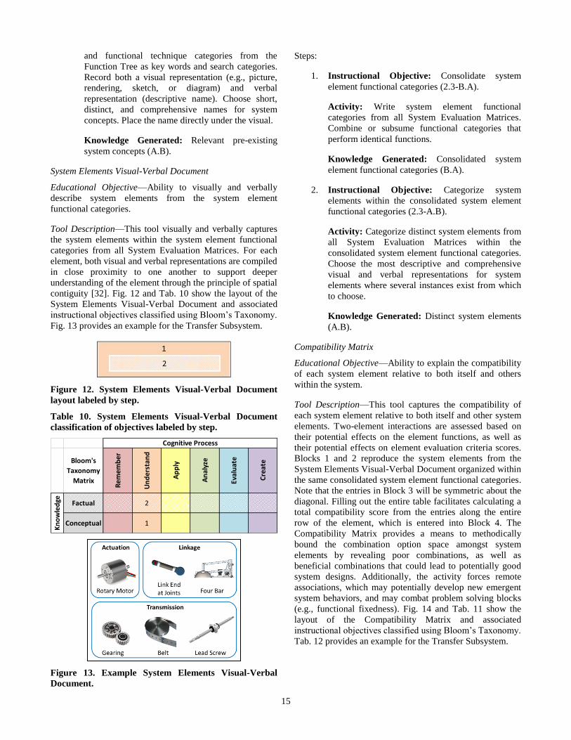
System Elements Visual-Verbal Document
Educational Objective—Ability to visually and verbally
describe system elements from the system element
functional categories.
Tool Description—This tool visually and verbally captures
the system elements within the system element functional
categories from all System Evaluation Matrices. For each
element, both visual and verbal representations are compiled
in close proximity to one another to support deeper
understanding of the element through the principle of spatial
contiguity [32]. Fig. 12 and Tab. 10 show the layout of the
System Elements Visual-Verbal Document and associated
instructional objectives classified using Bloom’s Taxonomy.
Fig. 13 provides an example for the Transfer Subsystem.
Figure 12. System Elements Visual-Verbal Document
layout labeled by step.
Table 10. System Elements Visual-Verbal Document
classification of objectives labeled by step.
Bloom's
Taxonomy
Matrix
Cognitive Process
Rem
emb
er
Un
der
stan
d
Ap
ply
An
alyz
e
Eval
uat
e
Cre
ate
Kn
ow
led
ge Factual 2
Conceptual 1
Figure 13. Example System Elements Visual-Verbal
Document.
Steps:
1. Instructional Objective: Consolidate system
element functional categories (2.3-B.A).
Activity: Write system element functional
categories from all System Evaluation Matrices.
Combine or subsume functional categories that
perform identical functions.
Knowledge Generated: Consolidated system
element functional categories (B.A).
2. Instructional Objective: Categorize system
elements within the consolidated system element
functional categories (2.3-A.B).
Activity: Categorize distinct system elements from
all System Evaluation Matrices within the
consolidated system element functional categories.
Choose the most descriptive and comprehensive
visual and verbal representations for system
elements where several instances exist from which
to choose.
Knowledge Generated: Distinct system elements
(A.B).
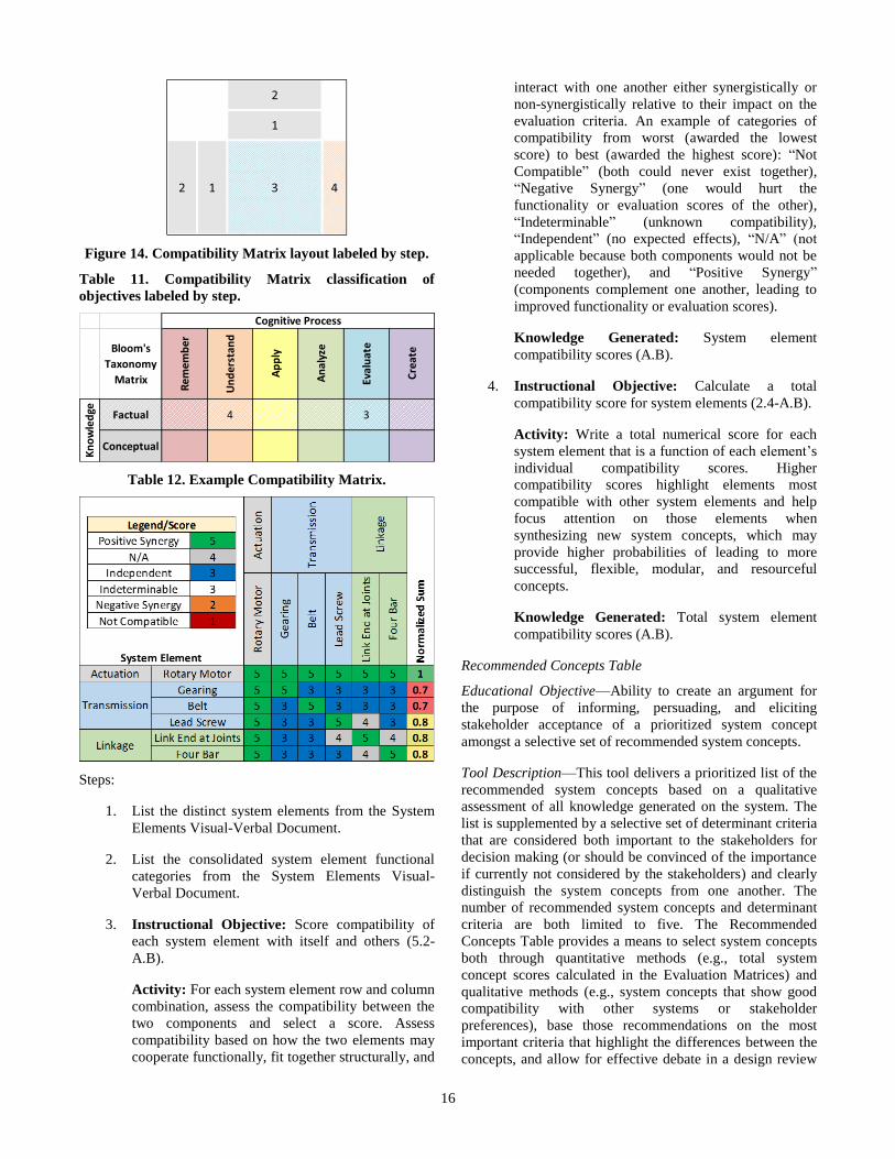
Compatibility Matrix
Educational Objective—Ability to explain the compatibility
of each system element relative to both itself and others
within the system.
Tool Description—This tool captures the compatibility of
each system element relative to both itself and other system
elements. Two-element interactions are assessed based on
their potential effects on the element functions, as well as
their potential effects on element evaluation criteria scores.
Blocks 1 and 2 reproduce the system elements from the
System Elements Visual-Verbal Document organized within
the same consolidated system element functional categories.
Note that the entries in Block 3 will be symmetric about the
diagonal. Filling out the entire table facilitates calculating a
total compatibility score from the entries along the entire
row of the element, which is entered into Block 4. The
Compatibility Matrix provides a means to methodically
bound the combination option space amongst system
elements by revealing poor combinations, as well as
beneficial combinations that could lead to potentially good
system designs. Additionally, the activity forces remote
associations, which may potentially develop new emergent
system behaviors, and may combat problem solving blocks
(e.g., functional fixedness). Fig. 14 and Tab. 11 show the
layout of the Compatibility Matrix and associated
instructional objectives classified using Bloom’s Taxonomy.
Tab. 12 provides an example for the Transfer Subsystem.
16
Figure 14. Compatibility Matrix layout labeled by step.
Table 11. Compatibility Matrix classification of
objectives labeled by step.
Bloom's
Taxonomy
Matrix
Kn
ow
led
ge Factual 4
Cognitive Process
Rem
emb
er
Un
der
stan
d
Ap
ply
An
alyz
e
Eval
uat
e
Cre
ate
3
Conceptual
Table 12. Example Compatibility Matrix.
Steps:
1. List the distinct system elements from the System
Elements Visual-Verbal Document.
2. List the consolidated system element functional
categories from the System Elements Visual-
Verbal Document.
3. Instructional Objective: Score compatibility of
each system element with itself and others (5.2-
A.B).
Activity: For each system element row and column
combination, assess the compatibility between the
two components and select a score. Assess
compatibility based on how the two elements may
cooperate functionally, fit together structurally, and
interact with one another either synergistically or
non-synergistically relative to their impact on the
evaluation criteria. An example of categories of
compatibility from worst (awarded the lowest
score) to best (awarded the highest score): “Not
Compatible” (both could never exist together),
“Negative Synergy” (one would hurt the
functionality or evaluation scores of the other),
“Indeterminable” (unknown compatibility),
“Independent” (no expected effects), “N/A” (not
applicable because both components would not be
needed together), and “Positive Synergy”
(components complement one another, leading to
improved functionality or evaluation scores).
Knowledge Generated: System element
compatibility scores (A.B).
4. Instructional Objective: Calculate a total
compatibility score for system elements (2.4-A.B).
Activity: Write a total numerical score for each
system element that is a function of each element’s
individual compatibility scores. Higher
compatibility scores highlight elements most
compatible with other system elements and help
focus attention on those elements when
synthesizing new system concepts, which may
provide higher probabilities of leading to more
successful, flexible, modular, and resourceful
concepts.
Knowledge Generated: Total system element
compatibility scores (A.B).
Recommended Concepts Table
Educational Objective—Ability to create an argument for
the purpose of informing, persuading, and eliciting
stakeholder acceptance of a prioritized system concept
amongst a selective set of recommended system concepts.
Tool Description—This tool delivers a prioritized list of the
recommended system concepts based on a qualitative
assessment of all knowledge generated on the system. The
list is supplemented by a selective set of determinant criteria
that are considered both important to the stakeholders for
decision making (or should be convinced of the importance
if currently not considered by the stakeholders) and clearly
distinguish the system concepts from one another. The
number of recommended system concepts and determinant
criteria are both limited to five. The Recommended
Concepts Table provides a means to select system concepts
both through quantitative methods (e.g., total system
concept scores calculated in the Evaluation Matrices) and
qualitative methods (e.g., system concepts that show good
compatibility with other systems or stakeholder
preferences), base those recommendations on the most
important criteria that highlight the differences between the
concepts, and allow for effective debate in a design review
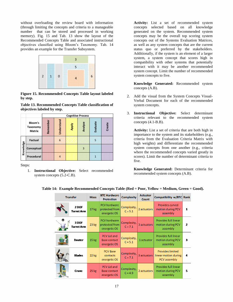
17
without overloading the review board with information
(through limiting the concepts and criteria to a manageable
number that can be stored and processed in working
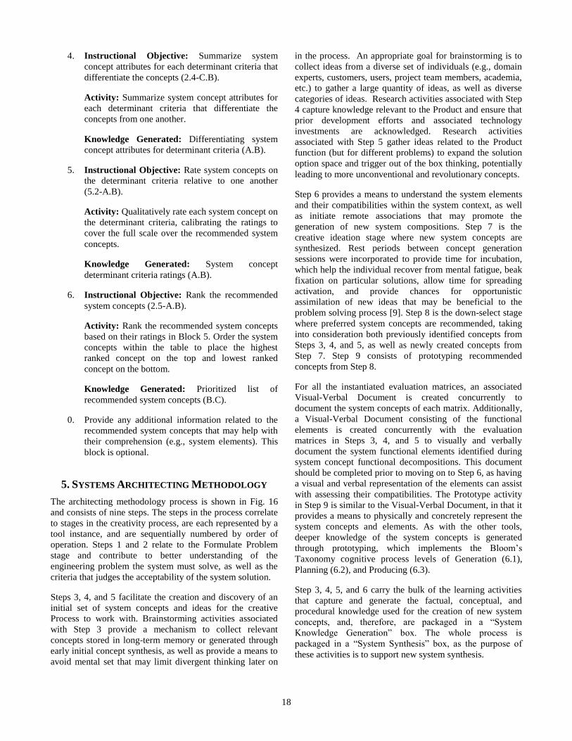
memory). Fig. 15 and Tab. 13 show the layout of the
Recommended Concepts Table and associated instructional
objectives classified using Bloom’s Taxonomy. Tab. 14
provides an example for the Transfer Subsystem.
Figure 15. Recommended Concepts Table layout labeled
by step.
Table 13. Recommended Concepts Table classification of
objectives labeled by step.
Bloom's
Taxonomy
Matrix
Procedural 4 1
Kn
ow
led
ge
Factual 6
Conceptual 3
Cognitive Process
Rem
emb
er
Un
der
stan
d
Ap
ply
An
alyz
e
Eval
uat
e
Cre
ate
5
Steps:
1. Instructional Objective: Select recommended
system concepts (5.2-C.B).
Activity: List a set of recommended system
concepts selected based on all knowledge
generated on the system. Recommended system
concepts may be the overall top scoring system
concepts out of the Systems Evaluation Matrices,
as well as any system concepts that are the current
status quo or preferred by the stakeholders.
Additionally, if the system is an element of a larger
system, a system concept that scores high in
compatibility with other systems that potentially
interact with it may be another recommended
system concept. Limit the number of recommended
system concepts to five.
Knowledge Generated: Recommended system
concepts (A.B).
2. Add the visual from the System Concepts Visual-
Verbal Document for each of the recommended
system concepts.
3. Instructional Objective: Select determinant
criteria relevant to the recommended system
concepts (4.1-B.B).
Activity: List a set of criteria that are both high in
importance to the system and its stakeholders (e.g.,
criteria from the Evaluation Criteria Matrix with
high weights) and differentiate the recommended
system concepts from one another (e.g., criteria
where the recommended concepts varied greatly in
scores). Limit the number of determinant criteria to
five.
Knowledge Generated: Determinant criteria for
recommended system concepts (A.B).
Table 14: Example Recommended Concepts Table (Red = Poor, Yellow = Medium, Green = Good).
18
4. Instructional Objective: Summarize system
concept attributes for each determinant criteria that
differentiate the concepts (2.4-C.B).
Activity: Summarize system concept attributes for
each determinant criteria that differentiate the
concepts from one another.
Knowledge Generated: Differentiating system
concept attributes for determinant criteria (A.B).
5. Instructional Objective: Rate system concepts on
the determinant criteria relative to one another
(5.2-A.B).
Activity: Qualitatively rate each system concept on
the determinant criteria, calibrating the ratings to
cover the full scale over the recommended system
concepts.
Knowledge Generated: System concept
determinant criteria ratings (A.B).
6. Instructional Objective: Rank the recommended
system concepts (2.5-A.B).
Activity: Rank the recommended system concepts
based on their ratings in Block 5. Order the system
concepts within the table to place the highest
ranked concept on the top and lowest ranked
concept on the bottom.
Knowledge Generated: Prioritized list of
recommended system concepts (B.C).
0. Provide any additional information related to the
recommended system concepts that may help with
their comprehension (e.g., system elements). This
block is optional.
5. SYSTEMS ARCHITECTING METHODOLOGY
The architecting methodology process is shown in Fig. 16
and consists of nine steps. The steps in the process correlate
to stages in the creativity process, are each represented by a
tool instance, and are sequentially numbered by order of
operation. Steps 1 and 2 relate to the Formulate Problem
stage and contribute to better understanding of the
engineering problem the system must solve, as well as the
criteria that judges the acceptability of the system solution.
Steps 3, 4, and 5 facilitate the creation and discovery of an
initial set of system concepts and ideas for the creative
Process to work with. Brainstorming activities associated
with Step 3 provide a mechanism to collect relevant
concepts stored in long-term memory or generated through
early initial concept synthesis, as well as provide a means to
avoid mental set that may limit divergent thinking later on
in the process. An appropriate goal for brainstorming is to
collect ideas from a diverse set of individuals (e.g., domain
experts, customers, users, project team members, academia,
etc.) to gather a large quantity of ideas, as well as diverse
categories of ideas. Research activities associated with Step
4 capture knowledge relevant to the Product and ensure that
prior development efforts and associated technology
investments are acknowledged. Research activities
associated with Step 5 gather ideas related to the Product
function (but for different problems) to expand the solution
option space and trigger out of the box thinking, potentially
leading to more unconventional and revolutionary concepts.
Step 6 provides a means to understand the system elements
and their compatibilities within the system context, as well
as initiate remote associations that may promote the
generation of new system compositions. Step 7 is the
creative ideation stage where new system concepts are
synthesized. Rest periods between concept generation
sessions were incorporated to provide time for incubation,
which help the individual recover from mental fatigue, beak
fixation on particular solutions, allow time for spreading
activation, and provide chances for opportunistic
assimilation of new ideas that may be beneficial to the
problem solving process [9]. Step 8 is the down-select stage
where preferred system concepts are recommended, taking
into consideration both previously identified concepts from
Steps 3, 4, and 5, as well as newly created concepts from
Step 7. Step 9 consists of prototyping recommended
concepts from Step 8.
For all the instantiated evaluation matrices, an associated
Visual-Verbal Document is created concurrently to
document the system concepts of each matrix. Additionally,
a Visual-Verbal Document consisting of the functional
elements is created concurrently with the evaluation
matrices in Steps 3, 4, and 5 to visually and verbally
document the system functional elements identified during
system concept functional decompositions. This document
should be completed prior to moving on to Step 6, as having
a visual and verbal representation of the elements can assist
with assessing their compatibilities. The Prototype activity
in Step 9 is similar to the Visual-Verbal Document, in that it
provides a means to physically and concretely represent the
system concepts and elements. As with the other tools,
deeper knowledge of the system concepts is generated
through prototyping, which implements the Bloom’s
Taxonomy cognitive process levels of Generation (6.1),
Planning (6.2), and Producing (6.3).
Step 3, 4, 5, and 6 carry the bulk of the learning activities
that capture and generate the factual, conceptual, and
procedural knowledge used for the creation of new system
concepts, and, therefore, are packaged in a “System
Knowledge Generation” box. The whole process is
packaged in a “System Synthesis” box, as the purpose of
these activities is to support new system synthesis.
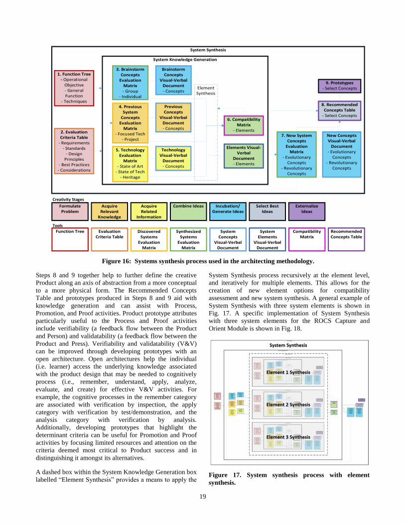
19
Steps 8 and 9 together help to further define the creative
Product along an axis of abstraction from a more conceptual
to a more physical form. The Recommended Concepts
Table and prototypes produced in Steps 8 and 9 aid with
knowledge generation and can assist with Process,
Promotion, and Proof activities. Product prototype attributes
particularly useful to the Process and Proof activities
include verifiability (a feedback flow between the Product
and Person) and validatability (a feedback flow between the
Product and Press). Verifiability and validatability (V&V)
can be improved through developing prototypes with an
open architecture. Open architectures help the individual
(i.e. learner) access the underlying knowledge associated
with the product design that may be needed to cognitively
process (i.e., remember, understand, apply, analyze,
evaluate, and create) for effective V&V activities. For
example, the cognitive processes in the remember category
are associated with verification by inspection, the apply
category with verification by test/demonstration, and the
analysis category with verification by analysis.
Additionally, developing prototypes that highlight the
determinant criteria can be useful for Promotion and Proof
activities by focusing limited resources and attention on the
criteria deemed most critical to Product success and in
distinguishing it amongst its alternatives.
A dashed box within the System Knowledge Generation box
labelled “Element Synthesis” provides a means to apply the
System Synthesis process recursively at the element level,
and iteratively for multiple elements. This allows for the
creation of new element options for compatibility
assessment and new system synthesis. A general example of
System Synthesis with three system elements is shown in
Fig. 17. A specific implementation of System Synthesis
with three system elements for the ROCS Capture and
Orient Module is shown in Fig. 18.
Figure 17. System synthesis process with element
synthesis.
Creativity Stages
Tools
Figure 16: Systems synthesis process used in the architecting methodology.
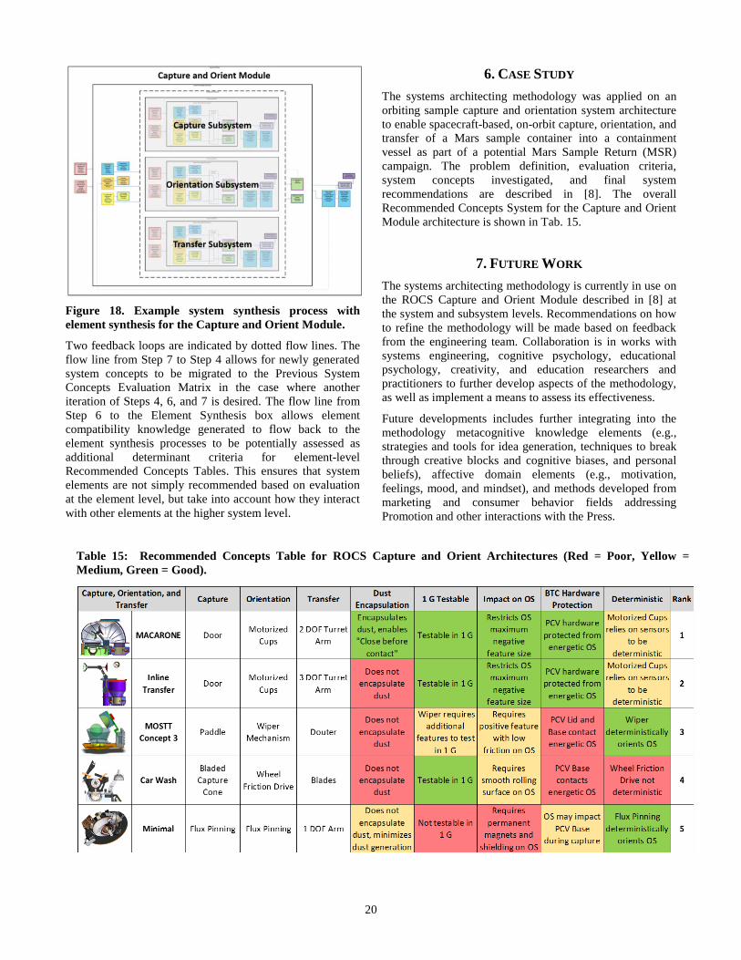
20
Figure 18. Example system synthesis process with
element synthesis for the Capture and Orient Module.
Two feedback loops are indicated by dotted flow lines. The
flow line from Step 7 to Step 4 allows for newly generated
system concepts to be migrated to the Previous System
Concepts Evaluation Matrix in the case where another
iteration of Steps 4, 6, and 7 is desired. The flow line from
Step 6 to the Element Synthesis box allows element
compatibility knowledge generated to flow back to the
element synthesis processes to be potentially assessed as
additional determinant criteria for element-level
Recommended Concepts Tables. This ensures that system
elements are not simply recommended based on evaluation
at the element level, but take into account how they interact
with other elements at the higher system level.
6. CASE STUDY
The systems architecting methodology was applied on an
orbiting sample capture and orientation system architecture
to enable spacecraft-based, on-orbit capture, orientation, and
transfer of a Mars sample container into a containment
vessel as part of a potential Mars Sample Return (MSR)
campaign. The problem definition, evaluation criteria,
system concepts investigated, and final system
recommendations are described in [8]. The overall
Recommended Concepts System for the Capture and Orient
Module architecture is shown in Tab. 15.
7. FUTURE WORK
The systems architecting methodology is currently in use on
the ROCS Capture and Orient Module described in [8] at
the system and subsystem levels. Recommendations on how
to refine the methodology will be made based on feedback
from the engineering team. Collaboration is in works with
systems engineering, cognitive psychology, educational
psychology, creativity, and education researchers and
practitioners to further develop aspects of the methodology,
as well as implement a means to assess its effectiveness.
Future developments includes further integrating into the
methodology metacognitive knowledge elements (e.g.,
strategies and tools for idea generation, techniques to break
through creative blocks and cognitive biases, and personal
beliefs), affective domain elements (e.g., motivation,
feelings, mood, and mindset), and methods developed from
marketing and consumer behavior fields addressing
Promotion and other interactions with the Press.
Table 15: Recommended Concepts Table for ROCS Capture and Orient Architectures (Red = Poor, Yellow =
Medium, Green = Good).
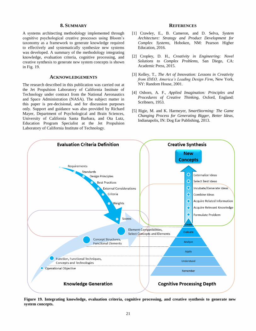
21
8. SUMMARY
A systems architecting methodology implemented through
cognitive psychological creative processes using Bloom’s
taxonomy as a framework to generate knowledge required
to effectively and systematically synthesize new systems
was developed. A summary of the methodology integrating
knowledge, evaluation criteria, cognitive processing, and
creative synthesis to generate new system concepts is shown
in Fig. 19.
ACKNOWLEDGEMENTS
The research described in this publication was carried out at
the Jet Propulsion Laboratory of California Institute of
Technology under contract from the National Aeronautics
and Space Administration (NASA). The subject matter in
this paper is pre-decisional, and for discussion purposes
only. Support and guidance was also provided by Richard
Mayer, Department of Psychological and Brain Sciences,
University of California Santa Barbara, and Ota Lutz,
Education Program Specialist at the Jet Propulsion
Laboratory of California Institute of Technology.
REFERENCES
[1] Crawley, E., B. Cameron, and D. Selva, System
Architecture: Strategy and Product Development for
Complex Systems, Hoboken, NM: Pearson Higher
Education, 2016.
[2] Cropley, D. H., Creativity in Engineering: Novel
Solutions to Complex Problems, San Diego, CA:
Academic Press, 2015.
[3] Kelley, T., The Art of Innovation: Lessons in Creativity
from IDEO, America’s Leading Design Firm, New York,
NY: Random House, 2001.
[4] Osborn, A. F., Applied Imagination: Principles and
Procedures of Creative Thinking, Oxford, England:
Scribners, 1953.
[5] Rigie, M. and K. Harmeyer, SmartStorming: The Game
Changing Process for Generating Bigger, Better Ideas,
Indianapolis, IN: Dog Ear Publishing, 2013.
Figure 19. Integrating knowledge, evaluation criteria, cognitive processing, and creative synthesis to generate new
system concepts.
22
[6] Gadd, K., TRIZ for Engineers: Enabling Inventive
Problem Solving, Wes Sussex, UK: John Wiley & Sons
Ltd., 2011.
[7] Ullman, D., The Mechanical Design Process, 5th ed. New
York, NY: McGraw-Hill Education, 2016.
[8] Younse, P., J. Strahle, M. Dolci, P. Ohta, K. Lalla, and E.
Olds, “An Orbiting Sample Capture and Orientation
Element Architecture for Potential Mars Sample Return,”
2018 IEEE Aerospace Conference, Big Sky, MT, Mar. 3-
10, 2018.
[9] Sawyer, R., Explaining Creativity, 2nd ed. Oxford, NY:
Oxford University Press, 2012.
[10] Rhodes, M., “An Analysis of Creativity,” The Phi Delta
Kappan, vol. 42, no. 7, pp. 305-310, 1961.
[11] Goldstein, E., Cognitive Psychology: Connecting Mind,
Research, and Everyday Experience, Stamford, CT:
Cengage Learning, 2015.
[12] Eysenck, M. W., Cognitive Psychology: A Student’s
Handbook, 7th ed. New York, NY: Psychology Press,
2015.
[13] Atkinson, R. C. and R. M. Shiffrin, Human Memory: A
Proposed System and its Control Processes, in K. W.
Spence, & J. T. Spence (Eds.), The Psychology of
Learning and Motivation Advances in Research and
Theory, vol. 2, pp. 89-195, New York, NY: Academic
Press, 1968.
[14] Baddeley, A., M. W. Eysenck, and M. C. Anderson,
Memory, 2nd ed. New York, NY: Psychology Press,
2014.
[15] Cowan, N., “The Magical Number 4 in Short-term
Memory: A Reconsideration of Mental Storage
Capacity,” Behavioral and Brain Sciences, 24, pp. 87-
185, 2000.
[16] Henke, K., “A Model for Memory Systems Based on
Processing Modes Rather than Consciousness,” Nature
Reviews Neuroscience, 11 (7), pp. 523-532, 2010.
[17] Baddeley, A., “Working Memory: Theories, Models, and
Controversies,” Annual Review of Psychology, 63, pp. 1-
29, 2012.
[18] Gluck. M., E. Mercado, and C. Myers, Learning and
Memory: From Brain to Behavior, 3rd ed. New York,
NY: Worth Publishers, 2016.
[19] Luck, S. J. and E. K. Vogel, “The Capacity of Visual
Working Memory for Features and Conjunctions,” Nature
Reviews Neuroscience, 390, pp. 279-281, Nov. 20, 1997.
[20] Weiten, W., Psychology: Themes and Variations, 10th
ed. Belmont, CA: Wadsworth, Cenage Learning, 2017.
[21] Sternberg, R., J. Kaufman, and E. Grigorenko, Applied
Intelligence, New York, NY: Cambridge University
Press, 2008.
[22] Mayer, R., Applying the Science of Learning, 2nd ed.
Boston, MA: Pearson Education, Inc., 2014.
[23] Bloom, B. S. (Ed.), Taxonomy of Educational
Objectives, New York, NY: David McKay, 1956.
[24] Anderson, L. (Ed.), D. Krathwohl (Ed.), P. Airasian, K.
Cruikshank, R. Mayer, P. Pintrich, J. Raths, and M.
Wittrock, A Taxonomy for Learning, Teaching, and
Assessing: A Revision of Bloom’s Taxonomy of
Educational Objectives, Complete ed. New York, NY:
Addison Wesley Longman, Inc., 2001.
[25] Kossiakoff, A., W. Sweet, S. Seymour, and S. Biemer,
Systems Engineering Principles and Practice, 2nd ed.
Hoboken, NJ: John Wiley & Sons, Inc., 2011.
[26] Blanchard, B. and W. Fabrycky, Systems Engineering
and Analysis, 5th ed. Upper Saddle River, NJ: Prentice
Hall, 2010.
[27] Akao, Y., Quality Function Deployment: Integrating
Customer Requirements into Product Design, Portland,
OR: Productivity Press, 1990.
[28] Pugh, S., Total Design: Integrated Methods for
Successful Product Engineering, Essex, England: Pearson
Education Ltd., 1991.
[29] Menold, J., K. W. Jablokow, D. M. Ferguson, S. Purzer,
and M. W. Ohland, “The Characteristics of Engineering
Innovativeness: A Cognitive Mapping and Review of
Instruments,” International Journal of Engineering
Education, Part A 32(1), pp. 64-83, 2016.
[30] Kurtz, D., Contemporary Marketing, 17th ed. Boston,
MA: Cengage Learning, 2016.
[31] Craik, F. and R. Lockhart, “Levels of Processing: A
Framework for Memory,” Journal of Verbal Learning
and Verbal Behavior, 11, pp. 671-684, 1972.
[32] Mayer, R., The Cambridge Handbook of Multimedia
Learning, 2nd ed. New York, NY: Cambridge University
Press, 2014.
[33] Leising, C., B. Sherwood, M. Adler, R. Wessen, and F.
Naderi, “Recent Improvements in JPL’s Mission
Formulation Process,” 2010 IEEE Aerospace Conference,
Big Sky, MT, Mar. 6-13, 2010.
[34] Pinto, J., Project Management: Achieving a Competitive
Advantage, 4th ed. Harlow, Essex, England: Pearson
Education Ltd., 2016.
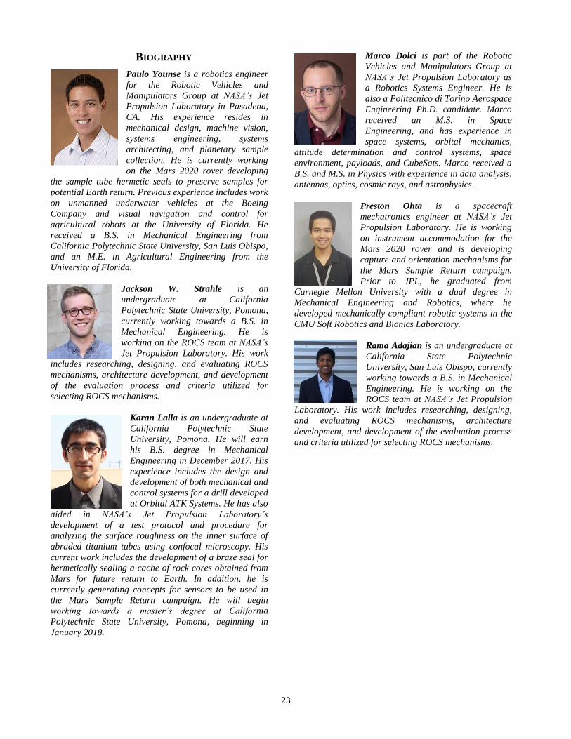
23
BIOGRAPHY
Paulo Younse is a robotics engineer
for the Robotic Vehicles and
Manipulators Group at NASA’s Jet
Propulsion Laboratory in Pasadena,
CA. His experience resides in
mechanical design, machine vision,
systems engineering, systems
architecting, and planetary sample
collection. He is currently working
on the Mars 2020 rover developing
the sample tube hermetic seals to preserve samples for
potential Earth return. Previous experience includes work
on unmanned underwater vehicles at the Boeing
Company and visual navigation and control for
agricultural robots at the University of Florida. He
received a B.S. in Mechanical Engineering from
California Polytechnic State University, San Luis Obispo,
and an M.E. in Agricultural Engineering from the
University of Florida.
Jackson W. Strahle is an
undergraduate at California
Polytechnic State University, Pomona,
currently working towards a B.S. in
Mechanical Engineering. He is
working on the ROCS team at NASA’s
Jet Propulsion Laboratory. His work
includes researching, designing, and evaluating ROCS
mechanisms, architecture development, and development
of the evaluation process and criteria utilized for
selecting ROCS mechanisms.
Karan Lalla is an undergraduate at
California Polytechnic State
University, Pomona. He will earn
his B.S. degree in Mechanical
Engineering in December 2017. His
experience includes the design and
development of both mechanical and
control systems for a drill developed
at Orbital ATK Systems. He has also
aided in NASA’s Jet Propulsion Laboratory’s
development of a test protocol and procedure for
analyzing the surface roughness on the inner surface of
abraded titanium tubes using confocal microscopy. His
current work includes the development of a braze seal for
hermetically sealing a cache of rock cores obtained from
Mars for future return to Earth. In addition, he is
currently generating concepts for sensors to be used in
the Mars Sample Return campaign. He will begin
working towards a master’s degree at California
Polytechnic State University, Pomona, beginning in
January 2018.
Marco Dolci is part of the Robotic
Vehicles and Manipulators Group at
NASA’s Jet Propulsion Laboratory as
a Robotics Systems Engineer. He is
also a Politecnico di Torino Aerospace
Engineering Ph.D. candidate. Marco
received an M.S. in Space
Engineering, and has experience in
space systems, orbital mechanics,
attitude determination and control systems, space
environment, payloads, and CubeSats. Marco received a
B.S. and M.S. in Physics with experience in data analysis,
antennas, optics, cosmic rays, and astrophysics.
Preston Ohta is a spacecraft
mechatronics engineer at NASA’s Jet
Propulsion Laboratory. He is working
on instrument accommodation for the
Mars 2020 rover and is developing
capture and orientation mechanisms for
the Mars Sample Return campaign.
Prior to JPL, he graduated from
Carnegie Mellon University with a dual degree in
Mechanical Engineering and Robotics, where he
developed mechanically compliant robotic systems in the
CMU Soft Robotics and Bionics Laboratory.
Rama Adajian is an undergraduate at
California State Polytechnic
University, San Luis Obispo, currently
working towards a B.S. in Mechanical
Engineering. He is working on the
ROCS team at NASA’s Jet Propulsion
Laboratory. His work includes researching, designing,
and evaluating ROCS mechanisms, architecture
development, and development of the evaluation process
and criteria utilized for selecting ROCS mechanisms.

24