rpt: re-architecting loss protection for content-aware networks
TRANSCRIPT

RPT: Re-architecting Loss Protection for Content-Aware Networks
Dongsu Han, Ashok Anand†, Aditya Akella†, Srinivasan SeshanCarnegie Mellon University †University of Wisconsin-Madison
AbstractWe revisit the design of redundancy-based loss protec-tion schemes in light of recent advances in content-awarenetworking. Content-aware networks minimizes the over-head of redundancy, if the redundancy is introduced in away that the network can understand. With this insight,we propose a new loss protection scheme called redun-dant packet transmission (RPT). Using redundant videostreaming as an example, we show that our approach, un-like FEC in traditional networks, provides low latencywith high robustness and is insensitive to parameter se-lection. We tackle practical issues such as minimizingthe impact on other traffic and the network. We showthat RPT provides a simple and general mechanism forapplication-specific control and flow prioritization.
1 IntroductionA variety of current and future Internet applications re-quire time critical or low latency communication. Exam-ple applications include delay-sensitive live/interactivevideo streams, online games, and video-based calls (e.g.,Apple’s FaceTime), all of which send real-time data. Stud-ies of real-time systems [36, 48] suggest that the maxi-mum tolerable one-way delay is around 150ms for real-time interaction. Within a data center, many soft real-timeapplications that interact with users require low latencycommunication [13]. Certain classes of inter-datacentertransfers, such as mirroring financial data, also requirereal-time communication [17].
The central challenge in supporting such delay-sensitive real-time applications is protecting them fromnetwork loss. One set of conventional approaches—acknowledgment-based retransmission protocols—arenot appropriate for real-time communication as retrans-missions triggered by timeouts can take several RTTs andviolate applications’ timing constraints [44, 51]. Anotherset of approaches—redundancy-based schemes such asForward Error Correction (FEC)—suffer from a funda-mental tension between robustness and the bandwidthoverhead [20, 25], making them either difficult to tune orinefficient in practice.
These techniques have been tuned to provide the bestperformance tradeoffs possible in traditional networks.In contrast, the focus of our paper is to show that bet-
ter protection against congestion losses may be possiblein content-aware networks. We use the term content-aware networks to refer to the variety of architecturalproposals [14, 32, 37, 42] and devices [2, 4, 10, 35] thatcache data and remove duplicates to alleviate congestion(i.e., they perform content-aware processing of packets).Content-aware processing is seeing ever-growing adop-tion in a variety of settings, including mobile and cellularnetworks [11], data centers [35], cloud computing [9],and enterprise networks [4]. The most popular of suchcontent-aware network devices are the WAN optimizers[5, 8, 10] that are typically placed at branch and main of-fices or between data-centers to reduce the traffic betweenthem. Market reports indicate that the market for suchdevices is growing rapidly [4].
Our core assumption is that content-aware network de-vices will be widely deployed across a variety of links infuture networks. Given this setting, we ask: (i) How dowe re-architect loss protection for delay sensitive appli-cations operating in this new context? (ii) Does content-awareness help simplify or further complicate the issuesthat existing loss protection schemes face? And, why?
We show that taking content-awareness into accountchallenges the conventional wisdom on the trade-offs ofredundancy in protecting against losses in time-criticaland delay-sensitive applications. In particular, we showthat it is now possible to use redundancy in a simple yetclever fashion to ensure robustness against congestionlosses while imposing little or no impact on the networkor on other existing applications. Equally importantly, weshow that it is now far easier to integrate loss protectionwith other design constraints such as adhering to tightdelay bounds.
We believe that the duplicate suppression actions incontent-aware frameworks provide a tremendous opportu-nity to use redundancy-based protection schemes. How-ever, redundancy must be introduced in the right way toensure: (a) the network can eliminate it optimally to pro-vide the desired efficiency and (b) the impact on otherapplications can be controlled.
We describe Redundant Transmission (RT) – a loss pro-tection scheme that intelligently sends multiple copies ofthe same data. The basic idea of RT is to expose the redun-dancy directly to the underlying content-aware network.

The simplest form of RT is to send multiple copies of thesame packet. When packets are not lost, the duplicatetransmissions in RT are compressed by the underlyingnetwork and add little overhead. In contrast, when thenetwork is congested, the loss of a packet prevents thecompression of a subsequent transmission. This ensuresthat the receiver still gets at least one decompressed copyof the original data. In some situations, the fact that packetlosses do not directly translate to less bandwidth use mayraise the concern that RT streams obtain an unfair shareof the network. However, existing congestion controlschemes, with some critical adjustments to accommodateRT behavior, can address this concern.
In essence, RT signals the network the relative impor-tance of packet by transmitting multiple copies. RT re-quires almost no tuning; this stands in stark contrast withthe difficulty of fine-tuning FEC-based approaches fortraditional networks. Finally, RT decouples redundancyfrom delay and easily accommodates application timingconstraints; in comparison, FEC schemes today closelytie delay guarantees with redundancy encoding since thereceiver cannot reconstruct lost packets until the batch iscomplete. In effect, RT on content-aware networks can ef-fectively support a variety of time-critical applications farbetter than existing approaches for traditional networks.
To illustrate the benefits of RT concretely, we use as anexample RPT, a simple variant of RT for real-time videoin a redundancy elimination network. Our evaluationof RPT, using a combination of real-world experiments,network measurements and simulations, shows that RPTdecreases the data loss rate by orders of magnitude morethan FEC schemes applicable to live communications. Asa result, it achieves better video quality than FEC for agiven bandwidth budget, or uses up to 20% less bandwidththan FEC schemes to deliver the same video quality.
We make the following contributions in this paper:1. We highlight the need to reconsider the design of
loss protection for content-aware networks. We show thatnetwork content-awareness enables vastly simpler andmore effective approaches to loss protection (§3).
2. We describe a redundancy scheme, RT, that canprovide a high degree of robustness at low overhead, andrequire minimal tuning (§3 and §4).
3. Through extensive experiments and simulations, wefind that RT can improve the robustness of real time mediaapplications with strict timing constraints (§6).
In the remaining sections, we review related work (§2),discuss realistic deployment examples as well as generalimplementation of RT on other content-aware networks(§5), and finally conclude in §7.
2 Current Loss Recovery SchemesPacket losses are often inevitable on the Internet, espe-cially across heavily-loaded links, such as cross-country
or trans-continental links. Many prior works use timeout-based retransmission to recover lost data [18, 27, 44, 49,51] on traditional networks. However, retransmissioncauses large delays [51] which are often difficult to hide.Also, the performance depends on correct timeout esti-mation [44] which is often non-trivial [18, 44]. Becauseof these intrinsic limitations, more sophisticated enhance-ments such as selective retransmission [27, 49], play-outbuffering [49], and modification to codecs [51] are oftenrequired to augment retransmission based loss recovery.
Another option is redundancy-based recovery, withFEC being an example framework that is widely usedtoday. While coding provides resilience, the use of FECis constraining in many ways in practice: (1) In FEC, thereceiver cannot recover lost packets until the batch is com-plete. This limits the size of the batch for delay-sensitiveapplications. For example, at most 5 packets are typicallybatched in video chat applications such as Skype [56]. (2)Small batch size makes FEC more susceptible to burstyloss. For example, adding a single coded FEC packet forevery five original data packets is not enough to recoverfrom two consecutive lost packets. Therefore, in prac-tice, the amount of redundancy used is high (e.g., 20%to 50% [20, 25, 56]), which is much higher than the un-derlying packet loss rate. (3) Furthermore, FEC needsto adapt to changing network conditions [19, 57], whichmakes parameter tuning even more difficult. Many stud-ies [29, 57] have shown that fine tuning FEC parameterswithin various environments is non-trivial.
More sophisticated redundancy-based recoveryschemes such as fountain codes [21], rateless coding withfeedback [30], and hybrid ARQ [43] introduce redun-dancy incrementally. However, fountain codes, ratelesscoding have been mostly used for bulk data transfer ornon-real-time streaming. Hybrid ARQ has been mostlyused in local wireless networks where the round-trip timeis much smaller compared to real-time delay constraints.When the round-trip time is comparable to real-timedelay constraints, incremental redundancy schemesdegenerate to FEC. Many other sophisticated schemessuch as multi-description coding [50] also use FEC toscale the video quality proportional to the bandwidth.While these schemes relax some of the above limitationsof FEC, the fundamental limitation of small batch size isinherent to delay-sensitive applications.
3 Redundant Packet TransmissionWe now describe the design of Redundant Packet Trans-mission (RPT), a simple variant of RT that sends fullyredundant packets for delivering interactive video streams.We envision a scenario in which real-time video trafficand other traffic coexist, with no more than 50% of thetraffic on a particular link being interactive, real-time traf-fic. We picked this scenario because it is representative
2
Switching
Fabric
Outgoing
interfaces
RE
Encode
RE cache
Incoming
interfaces
Virtual Output
QueuesRE
cache
RE
Decode
A’ A’ A
Decompressed packet
Compressed packet
Packets
Figure 1: Redundant Packet Transmission in a redun-dancy elimination router.
of forecasts of future network traffic patterns [3].To simplify exposition, throughout this section, we
assume that the RPT flows travel through a network withhop-by-hop Redundancy Elimination (RE) enabled [14].Later, in §5, we explore RT in content-aware networksof various other forms. As stated earlier, we assume thatpacket losses happen only due to congestion.
We start by providing background on RE. We thendescribe our basic idea, followed by a description of keybenefits and some comments on our approach.
3.1 Redundancy Elimination BackgroundIn Anand et al’s [14] design, RE is deployed across indi-vidual ISP links. An upstream router remembers packetssent over the link in a cache (each cache holds a few tensof seconds’ worth of data) and compares new packetsagainst cached packets. It encodes new packets on the flyby replacing redundant content (if found) with pointersto the cache. The immediate downstream router main-tains an identical packet cache, and decodes the encodedpacket. RE is applied in a hop-by-hop fashion.
RE encoding and decoding are deployed on the linecards of the routers as shown in Figure 1. Decodinghappens on the input interface before the virtual outputqueue, and encoding happens on the output interface.The router’s buffers (virtual output queues) contain fullydecoded packets.
3.2 Basic IdeaAs explained earlier, the basic idea of redundant packettransmission (RPT) is to send multiple copies of the samepacket. If at least one copy of the packet avoids networkloss, the data is received by the receiver. In current net-work designs, transmitting duplicate packets would incurlarge overhead. For example, if two duplicates of ev-ery original packet are sent, the overhead is 200% and a1Mbps stream of data would only contain 0.33Mbps oforiginal data. However, in networks with RE, duplicatecopies of packets are encoded into small packets, and thisoverhead would be significantly reduced.
Figure 1 illustrates how RPT works with redundancyelimination. From the input link, three duplicate packets
0.00
0.10
0.20
0.30
0.40
0.50
1E-7 1E-6 1E-5 1E-4 1E-3 1E-2 1E-1 1E+0 1E+1
Naive FEC(20,k)FEC(10,k) FEC(100,k)RPT(r) FEC(200,k)
Overh
ead
per
1M
bp
s S
tream
(Mb
ps)
Data lossrate(%)
RPT(3) RPT(2)
FEC(20,16) FEC(10,8)
FEC(100,90)
FEC(10,7)
FEC(10,9)
FEC(20,14)
FEC(10,6)
FEC(10,5)
RPT(4)
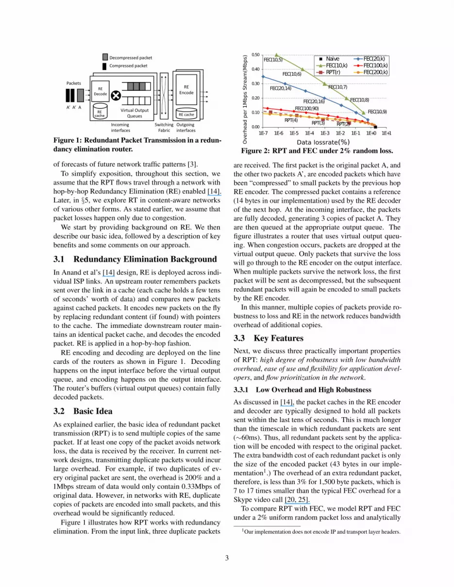
Figure 2: RPT and FEC under 2% random loss.
are received. The first packet is the original packet A, andthe other two packets A’, are encoded packets which havebeen “compressed” to small packets by the previous hopRE encoder. The compressed packet contains a reference(14 bytes in our implementation) used by the RE decoderof the next hop. At the incoming interface, the packetsare fully decoded, generating 3 copies of packet A. Theyare then queued at the appropriate output queue. Thefigure illustrates a router that uses virtual output queu-ing. When congestion occurs, packets are dropped at thevirtual output queue. Only packets that survive the losswill go through to the RE encoder on the output interface.When multiple packets survive the network loss, the firstpacket will be sent as decompressed, but the subsequentredundant packets will again be encoded to small packetsby the RE encoder.
In this manner, multiple copies of packets provide ro-bustness to loss and RE in the network reduces bandwidthoverhead of additional copies.
3.3 Key FeaturesNext, we discuss three practically important propertiesof RPT: high degree of robustness with low bandwidthoverhead, ease of use and flexibility for application devel-opers, and flow prioritization in the network.
3.3.1 Low Overhead and High Robustness
As discussed in [14], the packet caches in the RE encoderand decoder are typically designed to hold all packetssent within the last tens of seconds. This is much longerthan the timescale in which redundant packets are sent(∼60ms). Thus, all redundant packets sent by the applica-tion will be encoded with respect to the original packet.The extra bandwidth cost of each redundant packet is onlythe size of the encoded packet (43 bytes in our imple-mentation1.) The overhead of an extra redundant packet,therefore, is less than 3% for 1,500 byte packets, which is7 to 17 times smaller than the typical FEC overhead for aSkype video call [20, 25].
To compare RPT with FEC, we model RPT and FECunder a 2% uniform random packet loss and analytically
1Our implementation does not encode IP and transport layer headers.
3

derive the data loss of a 1Mbps RPT and FEC streams inan RE network. Figure 2 shows the resulting overheadand data loss rate. All flows operate on a fixed budgetbut splits its bandwidth between original data and redun-dancy. The overhead (y-axis) is defined as the amount ofredundancy in the stream, and the data loss (x-axis) as thepercentage of data that cannot be recovered. RPT(r) de-notes redundant streaming that sends r duplicate packets.FEC flows with various parameters are shown for compar-ison. FEC(n,k) denotes that k original packets are codedin to n packets. For FEC, we use a systematic coding ap-proach (e.g. Reed-Solomon) that sends k original packetsfollowed by n−k redundant packets. While both schemesintroduce redundancy, only the redundancy introduced byRPT gets minimized by the network unlike FEC whichdoes not introduce redundancy in a way that the networkunderstands; thus FEC over RE networks is identical inperformance to FEC over traditional networks.
FEC schemes, especially with a small group size (n), in-cur large overheads, and are much less effective in loss re-covery. For example, FEC(10,8), which adds 0.2 Mbps ofredundancy, has similar data loss rates as RPT(2), whichonly adds 0.03Mbps of redundancy. FEC with group size(n=200) performs similar to RPT. However, it takes 2.4seconds to transmit 200 1,500 byte packets at 1Mbps.This violates timing constraints of real-time communica-tions because a packet loss may only be recovered 2.4seconds later in the worst case. Thus, in practice, RPTprovides high robustness against packet loss at low over-head.
3.3.2 Ease of Use and Control
Application developers can easily tailor RPT to fit theirneeds. Three unique aspects of RPT help achieve thisproperty:
1) Detailed parameter tuning is not necessary.2) RPT allows per-packet redundancy control.3) Delay and redundancy are decoupled.
Ease of parameter selection: With FEC, the sender hasto carefully split its bandwidth between original and re-dundant data in order to maximize the video quality. Ifthe amount of redundancy is larger than the amount ofnetwork loss, the stream tolerates loss. However, thiscomes at the cost of quality because less bandwidth isused for real content. If the amount of redundancy is toolow, the effect of loss shows up in the stream and thequality degrades. This trade-off is clear in FEC(10,k)’sperformance in Figure 2. Determining the optimal pa-rameters for FEC is difficult and adapting it to changingnetwork conditions is even more so [29].
A unique aspect of RPT is that even though the actualredundancy at the sender is high, the network effectivelyreduces its cost. Therefore, the sender primarily has toensure that the amount of redundancy (r) is high enough to
tolerate the loss and worry much less about its cost, whichmakes RPT simple and easy to use. We show in §6.3 thatonly small amount of redundancy (r = 3) is good enoughfor a wide range of loss rates (1% to 8%), and a sub-optimal overshoot (i.e. unnecessary, extra redundancy)has very little impact on actual video quality.
Packet-by-packet redundancy control: RPT intro-duces redundancy for each packet as opposed to groups ofpackets, enabling packet-by-packet control of the extentof redundancy. More important packets, e.g., those corre-sponding to I-frames, could simply be sent more repeat-edly than others to increase robustness. In essence, RPTenables fine-grained unequal error protection (UEP) [33].Thus, RPT is simple to adapt to application-specific needsand data priorities.
Each encoded packet can be viewed as an implicit sig-nal to the network. Importance of the data is encoded inthe number of encoded packets, r−1. When an originalpacket gets lost, routers try to resend the original packetwhen the signal arrives. As such the network tries up to rtimes until one original copy of the packet goes through.
Decoupling of delay and redundancy: Unlike FEC,RPT separates the redundancy decision from delay. FECschemes closely tie timing with the encoding since thereceiver cannot reconstruct lost packets until the batch iscomplete. In contrast, RPT accommodates timing con-straints more easily. For example, sending 3 redundantpackets spaced apart by 5 ms is essentially asking everyrouter to retry up to 3 times every 5 ms to deliver the orig-inal packet. This mechanism lends itself to applicationspecific control to meet timing constraints. We furtherdiscuss the issues in controlling delay in §3.4.
3.3.3 Flow Prioritization
A unique property of RPT-enabled traffic is that it getspreferential treatment over other traffic under lossy con-ditions. RPT flows do not readily give up bandwidth asquickly as non-RPT flows. This is because for RPT flowspacket losses do not directly translate into less bandwidthuse due to “deflation” of redundant packets; subsequentredundant packets cause retransmission of the originalpacket when the original packet is lost. Therefore, RPTflows are effectively prioritized in congested environments.As a result, RPT could get more share at the bottlenecklink. We believe that this is a desirable property for pro-viding stronger guarantees about the delivery rate of data,and analyze this effect in §6. However, this preferentialtreatment may not be always desirable. In case wherefair bandwidth-sharing is desired, RPT is flexible enoughto be used with existing congestion control mechanismswhile retraining its core benefits. In §4, we provide analternative solution that retains other two benefits of RPTexcept flow prioritization.
4

…
…
Original packetRedundant packet
kSequence
Number
… …
k-d, …, k-(r-1)d, k-rd (k+1)-d, …, (k+1)-(r-1)d, (k+1)-rd
(k+1) (k+2)
d: delay, r: replication factor
(a) Sequence of packets sent by RPT(r)
k+2 kk-1 k-3
k
…
k-2 k-4
(k+1) (k+3)(k+2)
k k-2 k+1 k-1
(k+4) (k+5)
…
(b) Sequence of packets sent by RPT(3) with d=2
Figure 3: Sequence of packets sent by RPT
3.4 Scheduling Redundant PacketsWe now discuss detailed packet sequencing, i.e. howRPT interleaves redundant packets with original packets.Each original packet is transmitted without any delay,but we use two parameters to control the transmission ofredundant packets: redundancy (r) and delay (d).
Figure 3(a) shows the packet sequence of an RPT(r)flow. Original packets are sent without any delay, andr−1 redundant packets are sent compressed in betweentwo adjacent original packets. Thus, compared to a non-RPT flow of the same bitrate, r times as many packets aresent by a RPT(r) flow.
The delay parameter (d) specifies the number of origi-nal packets between two redundant packets that encodethe same data. The first redundant packet of sequencenumber n is sent after the original packet of sequencenumber (n+d). If the loss is temporally bursty, havinga large interval between two redundant packets will help.However, extra delay incurs extra latency in recoveringfrom a loss. So, delay (d) can be adjusted to meet thetiming requirements of applications.
Figure 3(b) shows an example with r = 3 and d = 2.Three copies of packet k is sent, each spaced apart by twooriginal packet transmissions. In §6.3, we evaluate RPT’ssensitivity to parameter selection.
3.5 Comments on RT/RPTIs this link-layer retransmission? Conceptually, RT issimilar to hop-by-hop reliability or link-layer retrans-mission. However, RT fits better with the end-to-endargument-based design of the Internet by giving end-points an elegant way to control the retransmission behav-ior inside the network. In contrast, hop-by-hop reliabilityschemes make it hard for applications to control the delayor to signify the relative importance of data. Similarly,in a naive hop-by-hop retransmission scheme, packetsare treated equally and can be delayed longer than theapplication-specific limit. RT exploits network’s content-awareness and provides a signaling mechanism on top ofsuch networks to achieve robustness against packet loss.Why not make video codecs resilient? In the specificcontext of video, prior works have proposed making
video codecs more resilient to packet loss. Examplesinclude layered video coding [46], H.264 SVC, variousloss concealment techniques [55] and codecs such asChitChat [56]. However, greater loss resilience does notcome for free in these designs; these designs typicallyhave lower compression rate than existing schemes orincorporate redundancy (FEC) in order to reconstruct thevideo with arbitrary loss patterns. Also they are oftenmore computationally complex than existing approaches,which makes them difficult to support on all devices [55].
Our scheme is agnostic to the choice of video codecand the loss concealment schemes used. Of course, theexact video quality gains may differ based on the lossrates, loss patterns and codec used.How does RT compare to more sophisticated cod-ing? Many sophisticated video coding schemes, suchas UEP [33], priority encoding transmission [12], andmultiple description coding [23, 50], typically use FEC(or Reed-Solomon codes) as a building block to achievegraceful degradation of video quality. Similarly, we be-lieve that RT can be used as a building block to enablemore sophisticated schemes. For example, one can sendmore important blocks of bits within a stream multipletimes. Furthermore, since RE networks also eliminatesub-packet level redundancy, a partially redundant packetmay also be used. We leave details of such techniquesas future work. In this work instead, we focus on under-standing the core properties of RT by comparing a basicform of RT with the most basic use of FEC.What about wireless errors? We do not yet know ifRT/RPT can be extended to protect against categories oflosses other than those due to congestion, e.g., partialpacket errors due to interference and fading. We do notethat there a variety of schemes that aim to provide ro-bust performance in such situations, some with a focuson video (e.g., the schemes in [38, 39, 53] for wirelesslinks). However, RT/RPT’s explicit focus on congestionlosses means that our approach is complementary to suchschemes. In our technical report [31], we discuss how RTcan happily coexist with such schemes.
4 RPT with Congestion ControlAs explained earlier, RPT flows are effectively prioritizedin congested environments2. However, in some environ-ments, fair bandwidth sharing may be more desirable. Insuch cases, the sending rate should adapt to the networkconditions to achieve a “fair-share”. To meet this goal,we apply TCP friendly rate control [28] (TFRC) to RPTflows. However, this raises surprisingly subtle problemsregarding the transmission rate and loss event rate es-timation that are germane to TFRC. We describe thesechallenges and our modifications to TFRC below.
2We further verify this later in §6.4.
5

Packet transmission: In TFRC for RPT, we calculatethe byte transmission rate from the equation just as theoriginal TFRC. Note that RPT(r) must send an originalpacket and r−1 duplicates. To match the byte sendingrate, we adjust the length of the packet so that equal num-ber of bytes are sent by TFRC RPT as the original TFRCin calculating the throughput. Thus, given a computedsend rate, TFRC RPT(r) sends r times as many packets.Note that each packet, original or duplicate, carries anindividual sequence number and a timestamp for TFRC’srate calculation purposes.Loss event rate estimation: In the original TFRC, thesending rate is calculated given the loss event rate p,where loss event rate is defined as the inverse of the aver-age number of packets sent between two loss events. Aloss event is a collection of packet drops (or congestionsignals) within a single RTT-length period.
Ideally, we would want TFRC RPT(r) to have the sameloss event rate as the original TFRC, as that would alsomake TFRC RPT obtain a TCP friendly fair share ofbandwidth. However, the observed loss event rate forRPT depends on the underlying packet loss pattern. Forease of exposition, we look at the two extremes of losspatterns: one that is purely random and the other that isstrictly temporally correlated.
Purely random packet drops may occur in a link of avery high degree of multiplexing. On the other hand, in astrictly temporal loss pattern, losses occur during specificintervals. One might see such a loss pattern when crosstraffic fills up a router queue at certain intervals. In reality,the two patterns appear inter-mixed depending on sourcetraffic sending patterns and the degree of multiplexing.
Next, we discuss how the two loss patterns impact lossevent rate estimation and the transmission rate:• Uniform random packet loss: In this setting, TFRC
RPT(r) behaves in a TCP friendly manner without anyadjustment to loss estimation. This is because the num-ber of packets sent between two loss events does notchange even though the packet sending rates change.
• Temporal packet loss: In this setting, packets are lostat specific times. During the time between loss, TFRCRPT(r) sends r times as many packets. Thus, the ob-served loss event rate for TFRC RPT(r) is only 1
r of thatof the original TFRC. Therefore, TFRC RPT wouldsend more traffic.
Adjusting the loss event rate: As stated earlier, in prac-tice, the two extreme patterns appear inter-mixed. Wetherefore want to choose an adjustment factor α so thatwhen the loss event rate is adjusted to α times the mea-sured loss event rate p, TFRC RPT(r) is TCP friendly. Asseen in the two extreme cases, α has values 1 for uniformrandom losses and r for temporal losses, respectively.So, in practice, α should be between 1 and r to achieveexact TCP-friendliness. A larger value of α makes the
WAN optimizer
WAN optimizer “Virtual wire”
RE endpoint
RE endpoint
Cross traffic
Video flows Branch Branch
Figure 4: Typical Deployment of WAN optimizers
TFRC-RPT react more aggressively to congestion events,and smaller value less aggressive than a TCP flow. Thismeans, even in the worst case, α can be r times off fromthe value which achieves exact TCP-friendliness. In thiscase, a TFRC-RPT flow would have performance similarto√
r many TFRC flows because the TCP-friendly rate isinversely proportional to
√p. Therefore, even an incor-
rect value of α would still make TFRC RPT friendly toa group of TCP connections and still react to congestionevents. In practice, we find in §6 that with TFRC-RPT(3),α = 1.5 closely approximates the bandwidth share of asingle TCP flow under wide range of loss rates and realis-tic loss patterns.
As such, RT is flexible enough to allow users to adjustthe degree of reactivity to congestion events while beinghighly robust. Regular RPT does not react to conges-tion events, and can be used to prioritize important flows.TFRC RPT reacts to congestion events and the reactiondegree can be controlled by the parameter α .
5 RPT in Various NetworksSo far, we have explored RPT on hop-by-hop RE net-works as a special case of redundant packet transmission.Here, we look at other deployment scenarios for content-aware devices as well as other content-aware designs.Corporate networks: WAN optimization is the mostpopular form of RE deployment in the real world. In atypical deployment, WAN optimizers are placed at branchand main offices or between data-centers to reduce thetraffic between them. Example deployments include 58+customers of Riverbed [10] and Cisco’s worldwide de-ployment to its 200+ offices [8]. While we envision RPTbeing used in future networks where content-aware de-vices are widely deployed, RPT can be deployed immedi-ately in such settings.
As shown in Figure 4, these sites have low bandwidthconnections using leased line or VPN-enabled “virtual”wires. ISPs offering VPN services typically provide band-width and data delivery rate (or packet loss) guarantees aspart of their SLA [1, 6]. In practice, their loss rate is oftennegligible because ISPs provision for bandwidth [24]. 3
Thus, the use of VPN and WAN optimizers effectivelycreates reliable RE “tunnels” on which RPT can operate.Important, real-time data can be sent with redundancy,
3Sprint’s MPLS VPN [6] had a packet loss rate of 0.00% within thecontinental US from Mar 2011 to Feb 2012.
6

RPT(3) FEC(6,5)
Overhead 9% 22%Data loss rate 8.0 x 10⁻⁶ 1.9 x 10⁻³
Table 1: Comparison of FEC and RPT over CCNand compete with other traffic when entering this tunnel.Packets will be lost when the total demand exceeds thecapacity of the tunnel, but RPT flows will have protectionagainst such loss. We evaluate this scenario in §6.2.
An alternative is to use traditional QoS schemes suchas priority queuing. However, this typically involves de-ploying extra functionalities including dynamic resourceallocation and admission control. For businesses not will-ing to maintain such an infrastructure, using RPT on andexisting RE-enabled VPN would be an excellent optionfor delivering important, time-sensitive data.Partial deployment: Not all routers in a network haveto be content-aware to use RPT. The requirement for“RPT-safety” is that RE is deployed across bandwidth-constrained links 4, and non-RE links are well provisioned.This is because non-RE links end up carrying severalduplicate packets. When such links are of much highercapacity, RPT causes no harm. Otherwise, it impactsnetwork utilization and harms other traffic. In §6.2, weexplore both cases through examples, and show how thenetwork utilization and the other traffic on the network areimpacted when RPT is used in an “unsafe” environment.
To ensure safe operation of RPT, one can detect thepresence of RE on bandwidth-constrained links, and useRPT only when it would not harm other traffic. In thissection, we outline two possible approaches for this, butleave details as a future work. One approach is to use end-point based measurement: for example, Pathneck [34]allows detection of bottlenecks based on available band-width. It sends traceroute packets in between load pack-ets and infers (multiple) bottleneck location(s) from thetime gap between returned ICMP packets. Similar tothis, we can send two separate packet trains: one withno redundancy and the other with redundancy r but withthe same bitrate. If all bandwidth constrained links areRE-enabled and RPT is safe to use on other links, thepacket gap would not inflate on previously detected bot-tlenecks and the redundant packet trains would not reportdifferent bottleneck links. Another way is to use systems,such as iPlane [45] and I-path [47], which expose pathattributes (e.g. available bandwidth) to end-hosts. Thesesystems can easily provide additional information such asRE-functionality for end-hosts to check for RPT safety.RPT over CCN: RPT also can be integrated with a broadclass of content-aware networks, including CCN [37] andSmartRE [15]. In our technical report [31], we explorediscuss how RPT can work atop SmartRE and wirelessnetworks. Here, we focus on applying RPT to CCN.
4This matches the common deployment scenario for RE [14, 54].
Quality Excellent Good Fair Poor Bad
PSNR (dB) > 37 31 ∼ 37 25 ∼ 31 20 ∼ 25 < 20
Table 2: User perception versus PSNR
In CCN, data consumers send “Interest” packets, andthe network responds with at most one “Data” packetfor each Interest. Inside the network, each router cachescontent and eliminates duplicate transfers of the samecontent over any link. CCN is designed to operate on topof unreliable packet delivery service, and thus Interestand Data packets may be lost [37].
We now compare RPT and FEC in CCN. Supposereal-time data is generated continuously, say k packetsevery 100 ms, and RTT is large. In an FEC-equivalentscheme for CCN, the content publisher would encode kdata packets and add (n− k) coded data packets, wheren > k. The data consumer would then generate n Interestpackets for loss protection. The receiver will be able tofully decode the data when more than k Interest and Datapackets go through. However, up to n Interest/Data pairswill go through the network when there is no loss. Incontrast, RPT does not code data packets, but generatesredundant Interest packets. This obviously provides ro-bustness against Interest packet loss. Moreover, when aData packet is lost, subsequent redundant Interest packetwill re-initiate the Data transfer. Since Interest packets aresmall compared to Data and duplicate Interests do not re-sult in duplicate transfers of the Data, the bandwidth costof redundancy is minimal. In RPT, at most k Data packetswill be transferred instead of n in the FEC scheme.
To demonstrate the benefit more concretely, we takethe Web page example from CCN and compare RPT andFEC over CCN. In the CCN-over-jumbo-UDP protocolcase [37], a client generates three Interest packets (325bytes) and receives five 1500-byte packets (6873 bytes)to fetch a Web page [37]. To compare RPT and FEC, weassume in RPT a redundancy parameter of 3 is used andin FEC the server adds one packet to the original data.Table 1 shows the overhead and data loss rate of eachscheme at the underlying loss rate 2%. The data loss ratesis the amount of data that could not be recovered. Eventhough the overhead of RPT is only 41% of that of FEC,it’s data loss rate is 240 times better. To achieve equal orgreater level of robustness than RPT(r = 3), FEC has tointroduce 11 times the overhead of RPT(r = 3).
6 EvaluationIn this section, we answer four specific questions throughextensive evaluation:(i) Does RPT deliver better video quality? How welldoes it work in practice?
In §6.2, we show that RPT provides high robustnessand low bandwidth overhead, which translate to higherquality for video applications.
7

(ii) Is RPT sensitive to its parameter setting, or doesit require fine tuning of parameters?
In §6.3, we show that, unlike FEC, RPT is easy to usesince careful parameter tuning is not necessary, and delaycan be independently controlled with the delay parameter.(iii) How do RT flows affect other flows and the overallnetwork behavior?
In §6.4, we demonstrate that RT flows are effectivelyprioritized over non-RT flows on congested links and mayoccupy more bandwidth than their fair-share.(iv) Can we make RT flows adapt to network condi-tions and be TCP-friendly?
We show in §6.5 that RT can also be made TCP-friendly, while retaining the key benefits.
6.1 Evaluation FrameworkWe use a combination of real-world experiments, networkmeasurements and simulations. We implemented an REencoder and decoder using Click [41], and created a routersimilar to that of Figure 1. Using this implementation, wecreate a hop-by-hop RE network in our lab as well as inEmulab. These serve as our evaluation framework.
We use implementation-based evaluation to show theoverall end-to-end performance of RPT, and simulationsto unravel the details and observe how it interacts withother cross traffic. To obtain realistic packet traces andloss patterns from highly multiplexed networks, we per-formed active measurements to collect real-world Internetpacket traces. We also created background traffic andsimulated RPT and FEC flows in a hop-by-hop RE net-work using the ns-2 simulator. These video flow packettraces are then fed into evalid video performance evalua-tion tool [40] to obtain the received video sequence withloss. For video, we used the football video sequence inCIF format, taken from a well-known library [7]. Weused H.264 encoding with 30 frames per second. I-frameswere inserted every second and only I- and P-frames wereused to model live streams.RE implementation: We implemented the Max-Matchalgorithm described in [14]. We further modified it toonly store non-redundant packets in the packet cache.Therefore, sending redundant packets does not interferewith other cached content. We use a small cache of 4MB.The implementation of the encoder encodes a 1500 bytefully redundant packet to a 43 byte packet5. We alsoimplemented RE in ns-2.Evaluation metric: We use the standard Peak-to-Signal-to-Noise Ratio (PSNR) [52] as the metric for the videoquality. PSNR is defined using a logarithmic unit ofdB, and therefore a small difference in PSNR results invisually noticeable difference in the video. The MPEGcommittee reportedly uses a threshold of PSNR = 0.5dB
5We do not compress network and transport layer headers. Thus, thepacket may be compressed even further in practice.
to test the significance of the quality improvement [52].Typical values for PSNR for encoded video are between30 and 50 dB. Table 2 maps the PSNR value to a userperceived video quality [40].
6.2 End-to-end Video PerformanceIn this section, we evaluate the end-to-end performanceof RPT and examine key characteristics.Experimental setting: First, we use our testbed based onour hop-by-hop RE implementation, and create a stream-ing application that uses redundant packet transmission.We create a topology where an RE router in the middleconnects two networks, one at 100Mbps and the otherat 10Mbps. To create loss, we generate traffic from thewell-connected network to the 10Mbps bottleneck link.
We generate a 1Mbps UDP video stream and long-running TCP flows as background traffic. We adjust thebackground traffic load to create a 2% loss on the videoflow. We then compare the video quality achieved by RPT,Naive, and FEC that use the same amount of bandwidth.We use RPT that has 6% overhead (r = 3,d = 2), andFEC(10,9) with 10% overhead, which closely match inlatency constraints with comparable overhead. Naive usesUDP without any protection.
Figure 5 shows the sending rate and the received datarate after the loss. The RPT and FEC senders respectivelyuse about 6% and 10% of their bandwidth towards redun-dancy, while the Naive sender fully uses 1Mbps to sendoriginal data. The sending rates of the three senders arethe same, within a small margin of error (1%). The Naivereceiver loses 2% of the data and receives 0.98Mbps be-cause of the loss. The FEC receiver only recovers about66% of the lost data due to the bursty loss pattern. On theother hand, the RPT receiver receives virtually all origi-nal data sent. Note that only the amount of redundancyhas slightly decreased. This is because when an originalpacket is lost, a subsequent redundant packet is naturallyexpanded inside the network.
As a result, the RPT flow gives much higher videoquality. Figure 6 shows a snapshot of the video for RPTand Naive flows. Table 3 shows the video quality of anencoded video and the received video. The encoded videocolumn shows the quality of video generated at the senderbefore packet loss. When RPT and FEC are used, theencoded video quality is slightly lower because of thebandwidth used towards redundancy. However, becausethe RPT flow is highly robust against loss, it providesthe best video streaming quality (1.8 dB better thanFEC and almost 6dB better than Naive).
RE-enabled Corporate VPN of §5 is the most com-mon deployment scenario of RT in today’s networks. Todemonstrate the feasibility of this scenario, we set upa network of four routers in Emulab [26] and createdan RE-enabled VPN tunnel that isolates the traffic be-
8

0.8 0.85 0.9 0.95 1
FEC receiver
FEC sender
RPT receiver
RPT sender
Naive receiver
Naive sender Original Data
Redundancy
0
Bandwidth use (Mbps)
0
Figure 5: Bandwidth use (a) RPT flow (b) Naive flow
Figure 6: Snapshot of the video
Encoded Received
RPT 37.3 dB 37.1 dBFEC 36.9 dB 35.3 dBNaive 37.5 dB 31.4 dB
Table 3: Average video quality(PSNR)
0
2
4
6
8
10
12
0
10
20
30
40
50
1 2 3 4 5 6 7 8 9 10
Encodedvideo RPTFEC NaïveUDPPacket LossRate
AveragePSNR(dB)
VideoSendingRate(Mbps)
PacketLossRate
(%)
Figure 7: Video quality and loss rate for real traces
tween two remote offices similar to that of Figure 4. Thephysical links between two remote offices have 100Mbpscapacity, and carries traffic from other customers. Wegenerate cross traffic over the physical links that carriesthe VPN traffic so that the physical links experience con-gestive loss. We allocate 5Mbps of bandwidth to theVPN-enabled “virtual” wire, which is emulated using thepriority queuing discipline from the Linux kernel’s trafficcontrol module. We introduced a 1Mbps video traffic and5 TCP connections between the two remote offices, andcompare RPT(3) and FEC(10,9) whose bandwidth over-head best matches to that of RPT(3), while adhering to thelatency constraint. The video stream experiences a lossrate of around 2.7% and the tunnel’s link utilization wasnearly 100% in both cases. The resulting PSNR of theRT flow and FEC were 37.1dB and 34.1dB respectively.This result shows that RT also works well on the mostcommon form of today’s content-aware networks.Real traces: To study the performance of RPT in a real-istic wide-area setting, we collected a real-world packettrace. We generated UDP packets from a university inKorea to a wired host connected to a residential ISP inPittsburgh, PA. The sending rate was varied from 1Mbpsto 10Mbps, each run lasting at least 30 seconds. Theround-trip-time was around 250ms, which indicates thatretransmissions would violate the timing constraint of aninteractive stream.
Assuming that the packet loss rates do not change sig-nificantly with RPT6, we apply the loss pattern obtainedfrom the measurement to an RPT flow, an FEC flow anda Naive UDP flow. For RPT, we use a redundancy pa-rameter of r = 3 and a delay parameter d = 2. For FEC,we choose the parameters so that the overhead matches
6We later verify this and see how RPT affects the loss rate in §6.4.
closest to that of RPT, while the additional latency in-curred by FEC at the receiver does not exceed 150ms,which results in different parameters for different sendingrates. Figure 7 shows the video quality for each scheme.The solid line shows the packet loss rate. The Encodedvideo bar shows the ideal PSNR without any loss whenall the bandwidth is used towards sending original data,presented as a reference. As the sending rate increases, thequality of the encoded video increases. However, the lossrate from Korea to U.S. was 3.5% at 1Mbps but increasedto 9.8% at 10Mbps as the sending rate increases. Becauseof the high loss rate, the naive UDP sender performspoorly (PSNR well under 30dB). FEC achieves betterperformance than naive, but much worse than RPT espe-cially under high loss rates. In contrast, RPT gives thebest performance, closely following the quality of theencoded video until the loss rate is about 8%. Evenat the higher loss rates, the impact on quality is muchless than the FEC scheme. This is because RPT givesmuch better protection against loss than FEC at similaroverhead. 7
6.3 Parameter Selection and SensitivityIn this section, we provide an in-depth performanceevaluation of RPT. In particular, we compare RPT andFEC’s parameter sensitivity using simulations that pro-duce packet loss patterns of highly multiplexed networkswith realistic cross traffic.Simulated RE Network: We use the ns-2 simulator tocreate a realistic loss pattern by generating a mix of HTTPand long-running TCP cross traffic. We use a dumbbelltopology with the RE-enabled bottleneck link capacityset to 100Mbps, and simulate a hop-by-hop RE networkand RPT flows. We generate 100 long-running TCP flowsand 100 HTTP requests per second. We used the pack-mime [22] module to generate representative HTTP trafficpatterns. We also generate ten video flows each having
7Large drop in PSNR at 8 Mbps is an artifact of the video’s resolutionbeing too small compared to its encoding rate and a particular pattern ofbursty data loss. When the video compression gets nearly lossless, evena small data loss causes PSNR to drop sharply. In addition, two originalpackets that are close together in sequence were lost by coincidence in8Mbps RPT. This had a more detrimental effect on the PSNR valuebecause the lost data belonged to the same video frame. The actual dataloss rate of the 8Mbps RPT flow was 0.165%, which is less than 0.174%of the 9Mbps RPT flow.
9

30
31
32
33
34
35
36
37
38 Encodedvideoat senderReceivedvideo
AveragePSNRoftheVideo(dB)
Figure 8: RPT’s performance is much less sensitive toits parameter setting.
Data Loss Rate (%)
0
0.1
0.2
0.3
0.4
1E-04 1E-03 1E-02 1E-01 1E+00 1E+01
NaiveFEC(10,k)FEC(10,k) randomFEC(100,k)FEC(100,k) randomRPT(r)RPT(r) random
Overh
ead
per
1M
bp
s (
Mb
ps)
RPT(4)
FEC(10,9)
FEC(10,6)
FEC(10,8)
FEC(10,7)
RPT(2)RPT(3) Naive
FEC(100,k)
Figure 9: Percent data loss rate and overhead: RPTgreatly outperforms FEC with small group size.
1Mbps budget regardless of the loss protection scheme ituses. The results presented are averages of ten runs witheach simulating five minutes of traffic. We first look at thefinal video quality seen by the end receiver under differentparameter settings, and then analyze the underlying lossrate and overhead.How do RPT flows and FEC flows perform with dif-ferent redundancy parameters? For RPT, we vary theredundancy parameter r from 2 to 5, while fixing the delayparameter d to 2. For FEC, we use a group size n = 10to meet the latency constraints and vary the number oforiginal data packets k from 5 to 9.
Figure 8 shows the quality of the video seen by the re-ceiver compared to the encoded quality at the sender. Theresult shows that RPT performs better than FEC’s best,and its performance is stable across different param-eter settings. In contrast, FEC’s performance is highlysensitive to the parameter selection. Therefore, with FEC,the sender has to carefully tune the parameter to balancethe amount of redundancy and encoding rate.
Figure 9 shows the underlying data loss rate and over-head of the video flows. The x-axis shows the data lossrate in log-scale, and the y-axis shows the amount ofoverhead. All video flows experience ∼2% packet loss.For comparison, the performance of RPT and two FECfamilies (n=10, 100) under uniform random loss (dottedlines) are also shown. RPT(4)’s data loss rate is severalorders of magnitude lower than the loss rate of FEC(10,9)whose overhead is similar. RPT(4) even performs betterthan FECs with large group size, such as FEC(100,91),whose latency exceeds the real-time constraint. FEC(10,7)achieve similar data loss rate to RPT(3) but has 6 times the
22
24
26
28
30
32
34
36
38
40
Naïve RPT(2) RPT(3) RPT(4)
Av
era
ge
PS
NR
(dB
)
Encoded video 1% random loss 2% random loss
4% random loss 6% random loss 8% random loss
Figure 10: Video quality under 1 to 8% loss. RPT(3)steadily delivers high quality even under high loss.
0.0001
0.001
0.01
0.1
1
delay=0 delay=1 delay=2
Uniform Random
Burst+
Burst++
Da
ta L
oss
Ra
te (
%)
Figure 11: Bursty loss increases the data loss espe-cially when the delay parameter is small.
overhead, which translated to 2dB difference in PSNR.The gap between the uniform loss and actual loss lines
in Figure 9 represents the effect of bursty loss perfor-mance. FEC(10,k) and RPT show a relatively large gapbetween the two lines. Analyzing the underlying loss pat-tern, we observe that within a group of 10 packets, lossesof 2 to 4 packets appear more frequently in the actual losspattern. This shows that the underlying traffic is bursty.On the other hand, loss bursts of more than 5 occur lessfrequently in the actual pattern because TCP congestioncontrol eventually kicks in.
We now show how the parameter should be set in RPT.How should we choose parameters in RPT? To answerthis question, we study how loss rate and burstiness of lossaffect the performance of RPT. First, we use the randomloss pattern and vary the packet loss rate from 1% to 8%.For RPT, we vary the redundancy parameter from 2 to 4,but fix the delay parameter at 2. For each loss rate, theaverage PSNR of a naive sender and an RPT sender isshown in Figure 10. It shows that video quality of RPT(3)is virtually immune to a wide range of packet losses; theaverage PSNR for RPT(3) under 8% loss only decreasedby 0.25dB compared to the zero-loss case. We, therefore,use r = 3 in the rest of our evaluation.
Second, we look at the role of the delay parameterunder bursty loss. For reference, we generate a 2% ran-dom loss, which on average has 1 lost packet every 50packets. We then create bursty loss patterns by reducingthe number of packets between losses by up to 15 and35, while keeping the average loss rate the same. Thethree cases are named as Uniform random, Burst+,and Burst++ respectively. Figure 11 shows the dataloss rate of RPT with different delay parameters underthe three loss conditions. An increase in burstiness nega-tively impacts the data loss rate, but as delay is increased
10

FEC(10,6) FEC(100,92) RPT(3)
No sender buffering 240ms 2400ms 60msSender buffering 180ms 1300ms -
Table 4: Maximum one-way delay of RT and FEC
the negative impact is decreased. In general, a large de-lay parameter gives more protection against bursty loss,but incurs additional latency. We use d = 2 and r = 3for RPT because of its superior performance in widerange of loss conditions.How much latency is caused by RPT and FEC flows?A loss might be recovered by subsequent redundant pack-ets; here we quantify the delay in this. In RPT(r) withdelay d, the receiver buffer must hold d · r packets. Sothe delay in RPT is d · r · intv, where intv is the intervalbetween packets. The RPT sender needs no additionalbuffering, as it transmits the packet as soon as a packetis generated from the encoder. In FEC, two alternativesexist where one does sender buffering to pace packetsevenly and the other doesn’t but further delays the trans-mission of redundant coded packets [31]. Table 4 showsthe delay caused by RPT and FEC for 1Mbps RPT(3)with d = 2 and FEC streams that exhibit similar data lossrate from Figure 9. We see that RPT gives a significantlylower delay than FEC schemes of similar strength inloss protection, and FEC(100,k) is not suitable for delay-sensitive communication.How do RPT and FEC flows perform under extremeload? One might think that in a highly congested linkwith a high fraction of RPT traffic, RPT flows would con-stantly overflow the buffer and the performance woulddrop. To create such a scenario with increased trafficload, we vary the fraction of video traffic in the link from10% to 90%, while keeping the number of backgroundTCP connections and bottleneck bandwidth the same. De-tailed evaluation is provided in [31]. In summary, wefind that RPT flows achieve close-to-ideal video quality,and better quality compared to the best FEC schemein all cases (10% to 80%) except for one very extremecase (90%) with very heavy cross traffic creating loss rate> 10%. The extreme case we portray in our experimentis unlikely to occur in practice for two reasons: 1) Theloss rates in practice are likely to be much lower. 2) Eventhe aggressive estimate suggests that no more than 15%of traffic in future will be real-time in nature [3].
6.4 Impact of RPT on the NetworkWe now examine the effect of RPT flows on other crosstraffic and the network. For this evaluation, we use thesame simulation setup and topology described in §6.3.How do other TCP flows perform? We look at the im-pact on two different types of TCP flows: long-runningTCP flows and HTTP-like short TCP flows.
To evaluate the impact on long-running TCP, we send
0 20 40 60 80 100
Non-RPT
RPT(2)
RPT(3)
RPT(4)
RPT(5)
Non-RPT
RPT(2)
RPT(3)
RPT(4)
RPT(5)
Non-RPT
RPT(2)
RPT(3)
RPT(4)
RPT(5)
Bottlenecklinkbandwidthusage(Mbit/sec)
50%
UDPGoodputUDPRedundancyTCPDuplicateTXTCPGoodput
Fractional bandwidthof video traffic atbottlenecklink
90%70%
Figure 12: Breakdown of bottleneck link utilization:RPT flows do not impact the link utilization. RPTflows are prioritized over competing TCP flows.
100 long-running TCP flows and a varying number ofvideo flows to vary the fraction of video traffic on thebottleneck link (from 10 to 90%). We also vary the re-dundancy parameter from 0 (Non-RPT) to 5. We use asmall router buffer size of 2·B·RT T√
100[16] to maximize the
negative impact.Figure 12 shows the bottleneck link traffic decompo-
sition in four categories8: UDP goodput, UDP redun-dancy, TCP duplicate, TCP goodput. UDP goodput isthe bandwidth occupied by the original packet and theUDP redundancy represents the bandwidth occupied bythe compressed packets. TCP goodput represents packetscontributing to application throughput, and TCP duplicateTx shows the amount of duplicate TCP packets received.
We observe that 1) the bandwidth utilization is notaffected by RPT, and 2) RPT flows are effectively pri-oritized over non-RPT TCP flows. In all cases the bot-tleneck bandwidth utilization was over 97.5%; TCP fillsup the bottleneck even if the router queue is occupied bymany decompressed redundant packets. TCP throughput,on the other hand, is impacted by the RPT flow espe-cially when the network is highly congested; e.g. in the90% video traffic case (bottom-most bars), TCP good-put (white region) decreases when RPT is used. Thisis because when RPT and non-RPT cross traffic com-petes, even though they experience the same underlyingpacket loss rates, for RPT flows packet loss do not directlytranslate into throughput loss. With redundant transmis-sions, the network recovers the loss through subsequentuncompressed redundant packets, effectively prioritizingthe RPT flows.
To see the impact on HTTP-type short flows, we lookat how RT changes the response time of short flows under
8Only a subset of results (video traffic occupying 50% to 90% ofbottleneck) shown for brevity, but all cases confirm the same results.
11

0 0.1 0.2 0.3 0.4 0.5 0.6 0.7 0.8 0.9
1
0 100 200 300 400 500
0 5000 10000 15000 20000
CD
F
HTTP Response Time (ms)
Size of HTTP Response (bytes)
w/ 90 Non-RPT flowsw/ 90 RPT(5) flows
HTTP Response Size
Figure 13: Response time and size for short HTTPflows (long flows omitted for clarity).
0
0.05
0.1
0.15
0.2
0.25
Non-RPT RPT(2) RPT(3) RPT(4) RPT(5)
10% 30%50% 70%90%
PacketLossRateof
videoflows
Fractionofvideotrafficoverall traffic
Figure 14: Impact on loss rate due to RPT flows.the setup described in §6.3. Figure 13 shows the CDFs ofthe size of the response messages, and the response times.To highlight the difference, we only show response timeswhen 90% of the traffic is video and RPT(5) is used, butthe trend is visible across all cases.
The response time for short flows decreases in thepresence of RPT flows. Since redundant packets in thequeue are compressed when they are sent out, the ser-vice rate of the queue increases with RT. Therefore thequeuing delay is reduced, which results in a decrease inthe response time. However, for larger flows (tail end ofthe figure) the response time actually increases, as theybehave more like long-running TCP flows, which obtainless throughput under congestion (Figure 12).How does network behavior change with RPT flows?There are subtle changes in loss rate and queuing delay.Loss rate: Figure 14 shows the packet loss rate of UDPvideo flows at the bottleneck router with varying amountof RPT traffic. When the fraction of video traffic ismoderate, adding more redundancy has little impacton the underlying packet loss of the video flow. This isbecause while redundant packets increase the load, theyalso increase the service rate of the link. However, weobserve that when RPT flows dominate the bottlenecklink, the underlying loss rate for video flows goes up as re-dundancy increases. The underlying reason for increasedloss is that under congestion RPT flows compete witheach other for bandwidth when most of the traffic is fromRPT flows. However, in §6.3, we saw that even undersuch extreme conditions RPT performs better than FEC.Queuing Delay: Figure 15 shows the average queuingdelay with varying redundancy parameters and varyingnumber of RPT flows. Redundant packets decreasequeuing delay. This is because redundant packets appearas decompressed at the router queue, but are sent out com-
510152025
Avera
ge Q
ueu
ing
D
ela
y (
ms)
10% 30%50% 70%90%
Fractionofvideotrafficover all traffic
Figure 15: Queuing delay is reduced with RPT flows.
0 2 4 6 8 10 12 14
RPT on non-RE link
RPT
FEC
Naïve Original Data
Redundancy
TCP background traffic
Bandwidth use (Mbps)
Tra
ffic
on
RE
-lin
k
Figure 16: No Harm: Bandwidth use on a non-RElink in the no harm case.
pressed at the bottleneck link. Therefore, as the number ofredundant packets increase, service rate becomes faster.What’s the impact of partial content-awareness? In§5, we noted that RT may cause harm in partially content-aware networks and should be used only after detectingRT-safety. Here, demonstrate both the no-harm and theharm case, and quantify the impact using our experimen-tal testbed, which has a 10Mbps and a 100Mbps RE link.
To demonstrate no-harm, we disabled the RE encoderon the non-bottleneck 100Mbps links of our testbed. Wethen generated an RPT flow and TCP background flowsthrough this 100Mbps link and the 10Mbps RE-enabledlink. Figure 16 shows the traffic on both links. The RPTflow occupying 1Mbps on an RE-enabled bottleneck linkintroduces almost 2Mbps of overhead (redundancy) onthe non-RE 100Mbps link. However, this causes no harmsince the 100Mbps link is not bandwidth constrained.
To demonstrate harm, we reduced the capacity of thenon-RE link to 15Mbps, and introduced four 1Mbps videoflows and a TCP flow. Table 5 compares bandwidth useon the 10Mbps RE link when the video flows are sentwith and without redundancy. When there’s no redun-dancy (Non-RPT), the link utilization of the 10Mbps linkis 97%. When RPT(3) is used, the 4Mbps video flowsoccupy 11.2Mbps on the non-RE link. This shifts thebottleneck to be the 15Mbps non-RE link, which forcesthe 10Mbps RE-link and the network to be under-utilizedat 76%. This verifies that in a partial deployment setting,detecting RT-safety is important as discussed in §5.
6.5 TCP-Friendly RPTRPT flows do not give up bandwidth as easily under con-gestion. In §4, we discussed an alternative that makes RPTflows achieve fair bandwidth sharing using TCP-friendlyrate control. In particular, we showed that incorporat-ing TFRC requires careful adjustment of loss event rate,and explained how it should be done in two distinct loss
12

Non-RPT RPT(3)
TCP traffic (Mbps) 5.7 3.6Video traffic (Mbps) 4.0 4.0Total (Utilization) 9.7 (97%) 7.6 (76%)
Table 5: Harm: Bandwidth use on a RE-link.
0
0.2
0.4
0.6
0.8
1
1.2
1 2 3 4
TFRC RPT(3)/TCP RENOTFRC RPT(3)/TCP SACKTFRC/TCP RENOTFRC/TCP SACK
Norm
aliz
ed
Th
rou
gh
pu
t of
TFR
C
Packet Loss Rate (%)
Figure 17: TFRC RPT under random loss.
patterns: Uniform random and Temporal packet loss.Is TFRC RPT TCP-friendly? We first evaluate ourscheme under the two extreme loss patterns created artifi-cially, and evaluate it under a more realistic loss pattern.
Uniform random loss: In this setting, TFRC RPT be-haves in a TCP friendly manner without any adjustmentin the loss estimation. Figure 17 shows the normalizedthroughput of TFRC and TFRC RPT(3) with respect toTCP Sack and Reno under 1% to 4% random loss. TFRCRPT(3) performs slightly better than TFRC because mul-tiple packet losses within an RTT are counted as oneloss event, and therefore the loss event rate for RPT(3) isslightly lower than that of normal TFRC.
Temporal packet loss: Here, we adjust the loss eventrate of TFRC RPT(r) to be r times the observed loss eventrate. To validate TCP-friendliness, we evaluated the per-formance of TFRC RPT(3) and TFRC under the sametemporal loss pattern. To create such a pattern, we gen-erated the same cross traffic, but artificially modified therouter’s queue so that redundant packets do not increasethe queue length. Indeed, the performance difference ofthe two was less than 3% with the adjusted loss event rate.
Realistic environment: The two cases appear in aninter-mixed way in practice. As discussed in §3, an adjust-ment factor between 1 and r is sufficient for TCP friend-liness. To create realistic loss patterns, we ran TFRCwith competing TCP flows. The same dumbbell topol-ogy with 1 Gbps bottleneck link capacity is used. Wevary the number of competing TCP flows from 200 to2000. Each flow’s RTT is randomly selected between40ms and 200ms. Among the TCP flows, five of themare set to have the same RTT as the TFRC flows. Wecompare the relative throughput of TFRC flows to the av-erage throughput of TCP flows. Our result shows TFRCRPT(3)’s performance reasonably matches that of TCPwhen α = 1.5 across various loss rates. Figure 18 showsthe normalized TFRC RPT(3)’s performance with respectto TCP Reno and TCP Sack. The result show that TFRCRPT is TCP friendly.
0
0.2
0.4
0.6
0.8
1
1.2
200 400 600 800 1000 1200 1400 1600 1800 2000
TFRC RPT(3)/TCP RENO
TFRC/TCP RENO
TFRC RPT(3)/TCP SACK
TFRC/TCP SACK
Norm
aliz
ed T
hro
ughput
of
TFR
C
Number of competingTCP flows
Figure 18: TFRC RPT exhibit TCP friendliness.
29303132333435363738394041
2.0Mbps 1.1Mbps 864Kbps 673Kbps 562Kbps
TFRC TFRC RPT(3) TFRC FEC
Avera
ge
PSN
R(d
B)
Throughput of TFRC RPT(3)
Figure 19: Video quality comparison.
Video quality: We created video streams using TFRCand TFRC RPT; in either case, we output video accordingto the TFRC’s or TFRC RPT’s sending rate.9 We com-pare the video quality of normal TFRC, normal TFRCwith FEC, and TFRC RPT under the same cross traffic.We vary the cross traffic to create TFRC flows whosethroughputs range from 562Kbps to 2.0Mbps. For TFRCwith FEC, we choose the parameter which gives the bestPSNR with delay under 150ms. Figure 19 shows thevideo quality achieved by the TFRC flows. We see thatTFRC RPT gives the best video quality in all cases.
7 ConclusionThis paper explores issues arising from the confluenceof two trends – growing importance and volume of real-time traffic, and the growing adoption of content-awarenetworks. We examine a key problem at this intersec-tion, namely that of protecting real-time traffic from datalosses in content-aware networks. We show that addingredundancy in a way that network understands reducesthe cost and increases the benefits of loss protection quitesignificantly. We refer to our candidate loss protection ap-proach as redundant transmission (RT). Using RedundantPacket Transmission (RPT) in redundancy-eliminationnetworks [14] as an example, we highlight various fea-tures of RT and establish that is a promising candidateto use in several practical content-aware networking sce-narios. We show that RT decreases the data loss rate byorders-of-magnitude more than typical FEC schemes ap-plicable in live video communications, and delivers higherquality video than FEC using the same bandwidth budget.RT provides fine-grained control to signal the importanceof data and satisfies tight delay constraints. Yet, it is easyto use as its performance is much less sensitive to param-eter selection. We show that constant bitrate RT flows
9For more details, refer to our technical report [31].
13

are prioritized over non-RT flows, but can share band-width fairly by incorporating TCP friendly rate controlinto RPT. We also show that RT provides an efficient andcost-effective loss protection mechanism in other generalcontent-aware networks.
AcknowledgmentsWe thank our shepherd Xiaowei Yang and anonymousreviewers for their feedback. This research was supportedin part by the National Science Foundation under awardsCNS-1040757, CNS-0905134, CNS-0905277 and CNS-1040801.
References[1] AT&T Businees Service Guide - AT&T VPN Service. http:
//new.serviceguide.att.com/portals/sgportal.portal?_nfpb=true&_pageLabel=avpn_page, 2011.
[2] Cisco Wide Area Application Services (WAAS) Software. http://www.cisco.com/en/US/prod/collateral/contnetw/ps5680/ps6870/prod_white_paper0900aecd8051d5b2.html, 2009.
[3] Cisco visual networking index: Forecast and methodology, 20092014.http://www.cisco.com/, 2010.
[4] Magic Quadrant for WAN Optimization Controllers. http://www.gartner.com/technology/media-products/reprints/riverbed/article1/article1.html, 2010.
[5] Juniper Networks Datasheet. http://www.juniper.net/us/en/local/pdf/datasheets/1000113-en.pdf, 2009.
[6] Sprint Network Performance. https://www.sprint.net/sla_performance.php?network=pip, 2012.
[7] YUV CIF reference videos. http://www.tkn.tu-berlin.de/research/evalvid/cif.html, 2010.
[8] Cisco Internal WAAS Implementation. http://blogs.cisco.com/ciscoit/cisco_internal_waas_implementation/, 2010.
[9] Riverbed Cloud Products. http://www.riverbed.com/us/products/cloud_products/cloud_steelhead.php, 2011.
[10] Riverbed Customer Stories. http://www.riverbed.com/us/customers/index.php?filter=bandwidth, 2011.
[11] Riverbed Steelhead Mobile. http://www.riverbed.com/us/products/steelhead_appliance/steelhead_mobile/,2011.
[12] A. Albanese, J. Bloer, J. Edmonds, M. Luby, and M. Sudan. Priority encod-ing transmission. IEEE Transactions on Information Theory, 42, 1994.
[13] M. Alizadeh, A. Greenberg, D. A. Maltz, J. Padhye, P. Patel, B. Prabhakar,S. Sengupta, and M. Sridharan. Data center TCP (DCTCP). In Proc. ACMSIGCOMM, 2010.
[14] A. Anand, A. Gupta, A. Akella, S. Seshan, and S. Shenker. Packet cacheson routers: the implications of universal redundant traffic elimination. InProc. ACM SIGCOMM, 2008.
[15] A. Anand, V. Sekar, and A. Akella. SmartRE: an architecture for coordi-nated network-wide redundancy elimination. In Proc. ACM SIGCOMM,2009.
[16] G. Appenzeller, I. Keslassy, and N. McKeown. Sizing router buffers. InProc. ACM SIGCOMM, 2004.
[17] M. Balakrishnan, T. Marian, K. Birman, H. Weatherspoon, and E. Vollset.Maelstrom: transparent error correction for lambda networks. In Proc.USENIX NSDI, 2008.
[18] A. C. Begen and Y. Altunbasak. Redundancy-controllable adaptive retrans-mission timeout estimation for packet video. In Proc. ACM NOSSDAV,2006.
[19] J.-C. Bolot, S. Fosse-Parisis, and D. Towsley. Adaptive FEC-based errorcontrol for internet telephony. In Proc. IEEE INFOCOM, 1999.
[20] O. Boyaci, A. Forte, and H. Schulzrinne. Performance of video-chat appli-cations under congestion. In Proc. IEEE ISM, Dec. 2009.
[21] J. W. Byers, M. Luby, M. Mitzenmacher, and A. Rege. A digital fountainapproach to reliable distribution of bulk data. In Proc. ACM SIGCOMM,1998.
[22] J. Cao, W. Cleveland, Y. Gao, K. Jeffay, F. Smith, and M. Weigle. Stochas-tic models for generating synthetic HTTP source traffic. In Proc. IEEEINFOCOM, volume 3, 2004.
[23] P. A. Chou, H. J. Wang, and V. N. Padmanabhan. Layered multiple descrip-tion coding. In Proc. Packet Video Workshop, 2003.
[24] Cisco. Deploying guaranteed-bandwith services with mpls.http://www.cisco.com/warp/public/cc/pd/iosw/prodlit/gurtb_wp.pdf, 2012.
[25] L. De Cicco, S. Mascolo, and V. Palmisano. Skype video responsiveness tobandwidth variations. In Proc. ACM NOSSDAV, 2008.
[26] Emulab. Emulab. http://www.emulab.net/.[27] N. Feamster and H. Balakrishnan. Packet loss recovery for streaming video.
In Proc. International Packet Video Workshop, 2002.[28] S. Floyd, M. Handley, J. Padhye, and J. Widmer. Equation-based conges-
tion control for unicast applications. In Proc. ACM SIGCOMM, 2000.[29] P. Frossard and O. Verscheure. Joint source/FEC rate selection for quality-
optimal MPEG-2 video delivery. IEEE Transactions on Image Processing,10(12), Dec. 2001.
[30] A. Hagedorn, S. Agarwal, D. Starobinski, and A. Trachtenberg. Ratelesscoding with feedback. In Proc. IEEE INFOCOM, 2009.
[31] D. Han, A. Anand, A. Akella, and S. Seshan. RPT: Re-architecting loss pro-tection for content-aware networks. Technical Report TR-11-117, CarnegieMellon Univ., 2011.
[32] D. Han, A. Anand, F. Dogar, B. Li, H. Lim, M. Machado, A. Mukundan,W. Wu, A. Akella, D. Andersen, J. Byers, S. Seshan, and P. Steenkiste. XIA:An architecture for an evolvable and trustworthy Internet. In Proc. USENIXNSDI, Apr. 2012.
[33] U. Horn, K. Stuhlmller, E. E. Herzogenrath, M. Link, and B. Girod. Ro-bust internet video transmission based on scalable coding and unequal errorprotection. Signal Processing: Image Communication, 1999.
[34] N. Hu, L. E. Li, and Z. M. Mao. Locating Internet bottlenecks: Algorithms,measurements, and implications. In Proc. ACM SIGCOMM, 2004.
[35] Infineta. Velocity Dedupe Engine. http://www.infineta.com/technology/reduce, 2011.
[36] ITU-T. Recommendation G.114 one-way transmission time.[37] V. Jacobson, D. K. Smetters, J. D. Thornton, M. F. Plass, N. H. Briggs, and
R. L. Braynard. Networking named content. In Proc. ACM CoNEXT, 2009.[38] S. Jakubczak and D. Katabi. A cross-layer design for scalable mobile video.
In Proc. ACM MobiCom, 2011.[39] K. Jamieson and H. Balakrishnan. PPR: Partial packet recovery for wireless
networks. In Proc. ACM SIGCOMM, Aug. 2007.[40] J. Klaue, B. Rathke, and A. Wolisz. EvalVid - a framework for video trans-
mission and quality evaluation. In Proc. Performance TOOLS, 2003.[41] E. Kohler, R. Morris, B. Chen, J. Jannotti, and M. F. Kaashoek. The click
modular router. ACM TOCS, 2000.[42] T. Koponen, M. Chawla, B.-G. Chun, A. Ermolinskiy, K. H. Kim,
S. Shenker, and I. Stoica. A Data-Oriented (and Beyond) Network Archi-tecture. Aug. 2007.
[43] H. Liu and M. El Zarki. Performance of H.263 video transmission overwireless channels using hybrid ARQ. IEEE JSAC, 15(9), Dec. 1997.
[44] D. Loguinov and H. Radha. On retransmission schemes for real-timestreaming in the Internet. In Proc. IEEE INFOCOM, 2001.
[45] H. V. Madhyastha, T. Isdal, M. Piatek, C. Dixon, T. E. Anderson, A. Kr-ishnamurthy, and A. Venkataramani. iPlane: An information plane for dis-tributed services. In Proc. 7th USENIX OSDI, Nov. 2006.
[46] S. McCanne, M. Vetterli, and V. Jacobson. Low-complexity video codingfor receiver-driven layered multicast. IEEE JSAC, 15(6), 1997.
[47] K. Nakauchi and K. Kobayashi. An explicit router feedback framework forhigh bandwidth-delay product networks. Comput. Netw., 51, May 2007.
[48] L. Pantel and L. C. Wolf. On the impact of delay on real-time multiplayergames. In Proc. NOSSDAV, 2002.
[49] C. Papadopoulos. Retransmission-based error control for continuous mediaapplications. In Proc. NOSSDAV, 1996.
[50] R. Puri and K. Ramchandran. Multiple description source coding usingforward error correction codes. In Proc. Asilomar conference on signals,systems, and computers, 1999.
[51] I. Rhee. Error control techniques for interactive low-bit rate video transmis-sion over the internet. In Proc. ACM SIGCOMM, 1998.
[52] D. Salomon. Data Compression; the Complete Reference. Springer, 2007.[53] S. Sen, N. K. Madabhushi, and S. Banerjee. Scalable wifi media delivery
through adaptive broadcasts. In Proc. USENIX NSDI, 2010.[54] N. T. Spring and D. Wetherall. A protocol-independent technique for elim-
inating redundant network traffic. In Proc. ACM SIGCOMM, 2000.[55] A. Suissa, J. Mellor, F. Lohier, and P. Garda. A novel video packet loss
concealment algorithm & real time implementation. In Proc. DASIP, 2008.[56] J. Wang and D. Katabi. ChitChat: Making video chat robust to packet loss.
Technical Report MIT-CSAIL-TR-2010-031, MIT, July 2010.[57] X. Zhu, R. Pan, N. Dukkipati, V. Subramanian, and F. Bonomi. Layered In-
ternet video engineering (LIVE): Network-assisted bandwidth sharing andtransient loss protection for scalable video streaming. In Proc. IEEE INFO-COM, 2010.
14